WO2012132096A1 - Adaptateur d'endoscope, processeur d'endoscope et système d'endoscope - Google Patents
Adaptateur d'endoscope, processeur d'endoscope et système d'endoscope Download PDFInfo
- Publication number
- WO2012132096A1 WO2012132096A1 PCT/JP2011/076509 JP2011076509W WO2012132096A1 WO 2012132096 A1 WO2012132096 A1 WO 2012132096A1 JP 2011076509 W JP2011076509 W JP 2011076509W WO 2012132096 A1 WO2012132096 A1 WO 2012132096A1
- Authority
- WO
- WIPO (PCT)
- Prior art keywords
- endoscope
- adapter
- processor
- identification information
- adjustment
- Prior art date
Links
Images


Classifications
-
- H—ELECTRICITY
- H04—ELECTRIC COMMUNICATION TECHNIQUE
- H04N—PICTORIAL COMMUNICATION, e.g. TELEVISION
- H04N7/00—Television systems
- H04N7/18—Closed-circuit television [CCTV] systems, i.e. systems in which the video signal is not broadcast
-
- A—HUMAN NECESSITIES
- A61—MEDICAL OR VETERINARY SCIENCE; HYGIENE
- A61B—DIAGNOSIS; SURGERY; IDENTIFICATION
- A61B1/00—Instruments for performing medical examinations of the interior of cavities or tubes of the body by visual or photographical inspection, e.g. endoscopes; Illuminating arrangements therefor
- A61B1/00002—Operational features of endoscopes
- A61B1/00004—Operational features of endoscopes characterised by electronic signal processing
- A61B1/00006—Operational features of endoscopes characterised by electronic signal processing of control signals
-
- A—HUMAN NECESSITIES
- A61—MEDICAL OR VETERINARY SCIENCE; HYGIENE
- A61B—DIAGNOSIS; SURGERY; IDENTIFICATION
- A61B1/00—Instruments for performing medical examinations of the interior of cavities or tubes of the body by visual or photographical inspection, e.g. endoscopes; Illuminating arrangements therefor
- A61B1/00002—Operational features of endoscopes
- A61B1/00059—Operational features of endoscopes provided with identification means for the endoscope
-
- A—HUMAN NECESSITIES
- A61—MEDICAL OR VETERINARY SCIENCE; HYGIENE
- A61B—DIAGNOSIS; SURGERY; IDENTIFICATION
- A61B1/00—Instruments for performing medical examinations of the interior of cavities or tubes of the body by visual or photographical inspection, e.g. endoscopes; Illuminating arrangements therefor
- A61B1/00112—Connection or coupling means
- A61B1/00121—Connectors, fasteners and adapters, e.g. on the endoscope handle
-
- A—HUMAN NECESSITIES
- A61—MEDICAL OR VETERINARY SCIENCE; HYGIENE
- A61B—DIAGNOSIS; SURGERY; IDENTIFICATION
- A61B1/00—Instruments for performing medical examinations of the interior of cavities or tubes of the body by visual or photographical inspection, e.g. endoscopes; Illuminating arrangements therefor
- A61B1/04—Instruments for performing medical examinations of the interior of cavities or tubes of the body by visual or photographical inspection, e.g. endoscopes; Illuminating arrangements therefor combined with photographic or television appliances
- A61B1/045—Control thereof
Definitions
- the present invention relates to an endoscope adapter, an endoscope processor, and an endoscope system.
- the endoscope insertion portion can be inserted into a body cavity of a patient or the inside of an inspection target, and observation of the inspection target region, image recording, or the like can be performed.
- the processor When an endoscope that can be attached to and detached from the processor is connected to the processor, the processor generates a drive signal for driving the image pickup device provided at the distal end portion of the endoscope insertion portion, and a video signal from the image pickup device.
- the image signal is processed to display an endoscopic image on the monitor.
- the processor cannot generate an appropriate endoscopic image without adjusting the white balance of the endoscopic image. That is, the processor obtains various adjustment parameters including a coefficient for white balance adjustment, drives the endoscope based on the adjustment parameters, and performs image processing on the received image signal.
- An endoscopic image can be generated and output to a monitor.
- an endoscope that holds adjustment parameters such as various gains as resistance values of a variable resistor can be connected to a processor via an adapter.
- Endoscopic devices have been proposed.
- the processor reads the resistance value via the adapter, determines an adjustment parameter from the resistance value, and performs driving and image processing for each endoscope based on the determined various adjustment parameters.
- the processor identifies the endoscope based on the identification information of the connected endoscope, and the identified endoscope is In the case of an endoscope connected for the first time, various adjustments such as white balance are performed. At that time, the processor obtains various adjustment parameters, and stores the various adjustment parameters in the nonvolatile memory of the endoscope.
- the processor determines whether the endoscope has already been connected when the endoscope is connected. Determine.
- the processor reads various adjustment parameters from the endoscope and uses them for driving the image sensor, image processing of the image signal, and the like. Therefore, once the white balance adjustment or the like is performed, the user does not need to perform an adjustment operation such as white balance adjustment every time after use.
- an adapter according to the above-mentioned proposal to connect another type of endoscope that is not a new type to a processor corresponding to the new type of endoscope.
- the adapter according to the above-described proposal can transmit the adjustment parameters of the endoscope to the processor through analog-to-digital conversion, but does not consider adjustment when the endoscope and the adapter are combined.
- the present invention can be used with the same usability as when using an endoscope that stores an endoscope connected to a processor using an adapter in a nonvolatile memory containing various adjustment parameters. It is an object of the present invention to provide an endoscope adapter, an endoscope system, and an endoscope processor.
- An endoscope adapter is an endoscope adapter that connects an endoscope including an imaging element that inputs and outputs analog signals and a processor that inputs and outputs digital signals.
- An image sensor drive signal generation circuit for generating a drive signal for driving the image sensor based on a drive control signal from the processor, and an analog image signal from the image sensor as a digital image signal in a serial signal format
- An image signal output circuit that converts and outputs to the processor, an endoscope identification information receiving circuit that receives endoscope identification information that is identification information of the endoscope, and identification information of the endoscope adapter
- An adapter identification information storage unit that stores certain adapter identification information, an adjustment parameter storage unit that stores adjustment parameters, and a description of the adjustment parameters from the processor
- the adjustment parameter received from the processor is stored in the adjustment parameter storage unit in response to the read command, and is stored in the adjustment parameter storage unit in response to the adjustment parameter read command from the processor.
- a control unit that controls to read out the adjustment parameter and output it to the
- An endoscope processor is a processor capable of inputting and outputting digital signals to an endoscope adapter to which an endoscope including an imaging element that inputs and outputs analog signals can be connected.
- the endoscope adapter includes an image sensor drive signal generation circuit that generates a drive signal for driving the image sensor based on a drive control signal from the processor, and an analog image from the image sensor.
- An image signal output circuit that converts a signal into a digital image signal in a serial signal format and outputs the digital image signal to the processor; an endoscope identification information receiving circuit that receives endoscope identification information that is identification information of the endoscope; An adapter identification information storage unit that stores adapter identification information that is identification information of the endoscope adapter, an adjustment parameter storage unit that stores adjustment parameters, and the processor The adjustment parameter received from the processor is stored in the adjustment parameter storage unit in response to the adjustment parameter write command from the processor, and the adjustment parameter is read in response to the adjustment parameter read command from the processor.
- a control unit that controls to read out the adjustment parameter stored in the parameter storage unit and output the parameter to the processor, and the processor includes a combination of the endoscope identification information and the adapter identification information.
- the adapter for endoscope In reference to the adjusted combination information storage unit for storing adjusted combination information indicating whether or not predetermined adjustment processing has been performed, and the adjusted combination information storage unit, the adapter for endoscope is referred to.
- the adjusted combination for the combination of the received endoscope identification information and the adapter identification information The presence / absence of information is determined, and when the adjusted combination information does not exist, the predetermined adjustment process is executed, and the adjustment parameter obtained by executing the adjustment parameter is the adjustment parameter of the endoscope adapter.
- the adjusted combination information related to the combination of the endoscope identification information and the adapter identification information is stored in the adjusted combination information storage unit, and the adjusted combination information exists.
- a controller that reads out the adjustment parameters stored in the adjustment parameter storage unit of the endoscope adapter.
- An endoscope system includes an endoscope adapter to which an endoscope including an imaging element that inputs and outputs analog signals can be connected, and a processor that inputs and outputs digital signals.
- An endoscope system wherein the endoscope adapter generates an image sensor drive signal generation circuit that generates a drive signal for driving the image sensor based on a drive control signal from the processor, and the imaging An image signal output circuit that converts an analog image signal from the element into a digital image signal in a serial signal format and outputs the digital image signal to the processor, and endoscope identification that receives endoscope identification information that is identification information of the endoscope
- the adjustment parameter received from the processor is stored in the adjustment parameter storage unit, and in response to the adjustment parameter read command from the processor.
- a control unit that reads and outputs the adjustment parameter stored in the adjustment parameter storage unit to the processor, the processor identifying the endoscope identification information and the adapter identification With reference to the adjusted combination information storage unit that stores adjusted combination information indicating whether or not predetermined adjustment processing has been performed in the combination of information, and the adjusted combination information storage unit, the endoscope The combination of the endoscope identification information received from the adapter for the adapter and the adapter identification information The presence / absence of adjusted combination information is determined, and if the adjusted combination information does not exist, the predetermined adjustment process is executed, and the adjustment parameter obtained by executing the adjustment parameter is stored in the endoscope adapter.
- FIG. 1 is a configuration diagram showing a configuration of an endoscope system according to the present embodiment.
- the endoscope system 1 includes a processor 11 that inputs and outputs digital signals and performs image processing and the like, a light source device 12, and a monitor 13 as a display device.
- the processor 11 and the light source device 12 are connected by a cable 14, and the processor 11 and the monitor 13 are connected by a cable 15.
- two types of endoscopes 21 and 31 can be connected to the light source device 12.
- the first type endoscope 21 includes a soft or hard insertion portion 22, an operation portion 23, a cable 24, and a connector 25 connected to the base end of the cable 24.
- An imaging element 22 a is mounted in the distal end portion of the insertion portion 22.
- the endoscope 21 can be attached to and detached from the connector portion 12 a of the light source device 12 via the connector 25.
- the connector 25 has a light guide 26 from which an end of the light guide for illumination light protrudes, and an electrical contact portion 27 including a plurality of contacts for various electrical signals.
- the connector portion 12 a includes an electrical contact portion 12 b having a plurality of contacts corresponding to the contact portion 27 and a light guide connector portion (not shown) for connecting the light guide 12 c corresponding to the light guide 26.
- the connector 25 and the connector part 12a also have a connection part for the air / water supply function, but the illustration and description of the connection part for the air / water supply are omitted here.
- the connector portion 12a collects illumination light from a lamp (not shown) in the light source device 12 on the end surface 26a of the light guide 26, and 25 contact portions 27 and the contact portion 12b of the connector portion 12 are configured to contact each other.
- the connector 25 when the connector 25 is connected to the connector portion 12 a of the light source device 12, the light from the light source device 12 passes through the light guide 26 of the connector 25 and the light guide inserted through the endoscope 21, and the distal end of the insertion portion 22. Is irradiated as illumination light. Further, by connecting the connector 25 to the connector portion 12 a of the light source device 12, the drive control of the image sensor 22 a disposed at the tip of the insertion portion 22 from the processor 11 and the imaging in the processor 11 are performed via the contact portion 27. It is possible to receive an image signal which is a video signal from the element 22a. Further, an operation signal in the operation unit 23 is also transmitted to the processor 11 through the contact unit 27.
- the endoscope 21 is, for example, a flash memory that is a nonvolatile memory for storing a unique identifier of the endoscope 21 (hereinafter referred to as endoscope ID information) and various adjustment parameter data in the connector 25. 25a.
- the endoscope ID information may be stored in a ROM provided separately.
- the processor 11 executes white balance processing, acquires various adjustment parameters, The various adjustment parameters are stored in the flash memory 25a of the endoscope 21.
- the processor 11 stores the endoscope ID information of the endoscope 21 that has performed the white balance adjustment. Therefore, when the endoscope 21 is connected, the processor 11 reads the endoscope ID information, and whether the endoscope 21 is connected for the first time based on the read endoscope ID information. Or whether it has already been connected in the past.
- the endoscope 21 can connect the connector 25 to the light source device 12 with one touch, and adjustment parameters such as a coefficient for white balance adjustment are stored in the flash memory 25a of the endoscope 21.
- the processor 11 uses the adjustment parameters stored in the flash memory 25a of the endoscope 21 to drive the imaging device 22a. Since a signal can be generated and image processing can be performed, the user does not need to perform adjustment work.
- the endoscope 31 of the second type includes an insertion portion 32, an operation portion 33, a cable 34, and a connector 35 connected to the proximal end of the cable 34.
- An imaging element 32a for inputting and outputting analog signals is mounted in the distal end portion of the insertion portion 32.
- the endoscope adapter 41 (hereinafter referred to as an adapter) 41 is configured to be connectable to the connector 35 of the endoscope 31, the endoscope 31 attaches the adapter 41 to the connector 35. By mounting, it can be detachably connected to the connector portion 12a of the light source device 12 via the adapter 41.
- the adapter 41 includes a ROM 41a that stores ID information of the adapter 41 (hereinafter referred to as adapter ID information) and a flash memory 41b that is a nonvolatile memory capable of storing various adjustment parameters.
- the second type endoscope 31 is also a type of endoscope that has endoscope ID information but cannot store adjustment parameters such as a coefficient for white balance adjustment in combination with the processor 11.
- the second type endoscope 31 is an old type endoscope, and is originally used by connecting to another light source device and another processor. That is, the second type endoscope 31 is used in combination with another processor, but by using the adapter 41, a new processor 11 for the first type endoscope 21 is used. Can be used in combination.
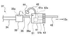
- FIG. 2 is a diagram for explaining the configuration of the adapter 41.
- the adapter 41 is configured to be connectable to the connector 35 of the endoscope 31.
- the adapter 41 is configured to be connectable to the connector portion 12 a of the light source device 12. Therefore, the adapter 41 has a light guide 42 from which the end of the light guide for illumination light protrudes, and an electrical contact portion 43 including a plurality of contacts for various electrical signals. That is, the adapter 41 is an endoscope adapter that connects the endoscope 31 including the imaging element 32a to / from which analog signals are input / output and the processor 11 to / from which digital signals are input / output.
- the configuration of the contact portion 43 is the same as that of the contact portion 27 of the connector 25 of the endoscope 21.
- the adapter 41 is configured such that when the connector 35 is connected, the end surface 36a of the light guide 36 protruding to the proximal end side of the connector 35 comes into contact with the end surface 42a on the distal end side of the light guide 42 of the adapter 41.
- the proximal end of the light guide is such that illumination light from a lamp (not shown) in the light source device 12 is received by the light guide 42 when the adapter 41 in the light source device 12 is connected to the connector 25a of the light source device 12.
- the light guide 42 is a light transmission member that transmits light from the light source device 12 to the light guide 36 of the endoscope 31.
- the adapter 41 has an electrical connector 44 for connecting to the electrical connector 35a of the connector 35.
- the connector 44 is provided at the end of the cable 45 that extends from the adapter 41.
- the adapter 41 contains a circuit board 51 on which various circuits to be described later are mounted.
- the circuit board 51 is connected to the cable 45 through various signal lines 51a, and is connected to the contact portion 43 through various signal lines 51b.
- the adapter 41 to which the connector 35 is connected to the connector portion 12 a of the light source device 12 By connecting the adapter 41 to which the connector 35 is connected to the connector portion 12 a of the light source device 12, the light from the light source device 12 passes through the light guide 42 of the adapter 41, the light guide 36 of the connector 35, and the endoscope 31. The light is irradiated as illumination light from the tip of the insertion portion 32 through the inserted light guide (not shown). Further, by connecting the adapter 41 to which the connector 35 is connected to the connector portion 12 a of the light source device 12, the processor 11 can connect the distal end of the insertion portion 32 via the electrical connectors 35 a and 44, the cable 45, and the contact portion 43. It is possible to supply a drive signal to the image sensor 32a disposed in the image sensor and to receive an image signal that is a video signal from the image sensor 32a. Further, an operation signal in the operation unit 33 is also transmitted to the processor 11 through the contact unit 43.
- the electrical connector 44 is connected to the electrical connector 35a, and the adapter 41 is attached to the connector portion 12a of the light source device 12.
- the circuit board 51 and the endoscope 31 are connected via various signal lines 51a, cables 45, and electrical connectors 44 and 35a. Further, the circuit board 51 and the processor 11 include various signal lines 51b, contact portions 43, 12b and the cable 14 are connected.
- the processor 11 can connect not only the first type endoscope 21 but also the second type endoscope 31 by using the adapter 41.
- the first type endoscope 21 incorporates the flash memory 25a in which ID information unique to the endoscope 21 and various adjustment parameters can be stored. Can be read and various adjustment parameters can be written.
- the second type of endoscope 31 has ID information based on the resistance value of a variable resistor or the like, but cannot be used to store various adjustment parameter information in combination with the processor 11. It is a mirror.
- the second type of endoscope 31 is originally used in combination with another processor. However, each time the endoscope 31 is used, various adjustment operations are performed, and the processor sets various adjustment parameters. Since it is necessary to acquire information, it is troublesome for the user.
- the user can use the second type endoscope 31 with the same usability as the first type endoscope 21.
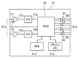
- FIG. 3 is a block configuration diagram of the substrate 51 of the adapter 41.
- the substrate 51 includes a field programmable gate array (hereinafter referred to as an FPGA) 61 that executes various processes, a ROM 41a, and a flash memory 41b.
- FPGA field programmable gate array
- the various signal lines 51a are connected to a signal line 71, a signal line 72, and a signal line 73, which are mounted on the substrate 51, respectively.
- the signal line 71 is a signal line for receiving an image signal from the imaging element of the endoscope 31.
- the signal line 72 is a signal line for outputting a drive pulse signal for driving the image sensor.
- the signal line 73 is a signal line for receiving an analog signal corresponding to the endoscope ID information of the endoscope 31.
- the substrate 51 is connected to a buffer circuit 71 a that receives an image signal connected to the signal line 71, an analog-digital converter (hereinafter referred to as an A / D converter) 71 b that is connected to the buffer circuit 71 a, and a signal line 73.
- the buffer circuit 73a, the A / D converter 73b, and the I / F 96 constitute an endoscope identification information receiving circuit that receives endoscope identification information that is identification information of the endoscope 31. Note that when the endoscope ID information can be received from the endoscope 31 as a digital signal, the A / D converter 73b is unnecessary.
- the various signal lines 51 b are connected to a differential output circuit 81, a differential input circuit 82, a differential output circuit 83, and a differential input circuit 84, each mounted on the substrate 51.
- the differential output circuit 81 is a circuit for outputting an image signal from the imaging device 32a of the endoscope 31 to the processor 11 as a differential signal.
- the differential input circuit 82 is a circuit for inputting a drive clock signal from the processor 11 to the imaging device 32a of the endoscope 31 as a differential signal.
- the differential output circuit 83 is a circuit for outputting data read from the ROM 41a and the flash memory 41b to the processor 11 as a differential signal.
- the differential input circuit 84 is a circuit for receiving various commands from the processor 11 and data from the processor 11 written in the flash memory 41b as differential signals.
- the FPGA 61 converts the parallel image signal from the signal line 71 into a serial image signal and outputs the serial image signal to the differential output circuit 81, and the single drive clock signal of the differential signal from the differential input circuit 82. A process of converting and outputting a drive pulse signal is executed.
- the FPGA 61 receives the ID information of the endoscope 31 and outputs it to the differential output circuit 83, and the endoscope ID of the endoscope 31 according to various information read commands from the differential input circuit 84.
- the ROM 41 a is an adapter identification information storage unit that stores adapter identification information that is identification information of the adapter 41.
- the ROM 41a stores drive pulse generation information such as a pulse period and voltage of a drive signal corresponding to the type of the image sensor 32a of the second type endoscope 31. This is because the pulse period of the drive signal differs depending on the type and specification of the image sensor 32a.
- the adapter 41 may not hold the drive pulse generation information if the type of the image sensor 32a mounted on the endoscope 31 has the same drive signal cycle, voltage, and the like.
- the drive pulse generation information may be held by the processor 11 and the corresponding drive pulse generation information may be supplied to the adapter 41 based on the endoscope ID information from the adapter 41.
- the flash memory 41b stores various adjustment parameters according to the connected endoscope 31.
- the flash memory 41b constitutes an adjustment parameter storage unit that stores adjustment parameters.
- the adapter ID information may be stored in the flash memory 41b.
- FIG. 4 is a block configuration diagram of the FPGA 61.
- the FPGA 61 includes a control unit 91, a driver unit 92, parallel / serial converters (hereinafter referred to as P / S converters) 93 and 94, a serial / parallel converter (hereinafter referred to as S / P converter) 95, and an interface (I / P).
- F Including 96.
- the control unit 91 Based on the endoscope ID information, the control unit 91 reads drive pulse generation information corresponding to the imaging element 32a of the connected endoscope 31 and controls the driver unit 92. In addition, the control unit 91 transmits the endoscope ID information, adapter ID information, and various adjustment parameters of the endoscope 31 to the processor 11 in response to a transmission request command from the processor 11. In response to the various adjustment parameter write request commands, the flash memory 41b is written.
- control unit 91 when receiving the adjustment parameter read command from the processor 11, the control unit 91 reads the adjustment parameter corresponding to the endoscope ID information of the connected endoscope 31 from the flash memory 41 b, and the processor 11. Execute the process to send to.
- control unit 91 stores various adjustment parameters received from the processor 11 in the flash memory 41b in response to the adjustment parameter write command from the processor 11, and uses the various adjustment parameter read commands from the processor 11 as commands. In response to this, the control unit controls the various adjustment parameters stored in the flash memory 41b to be read out and output to the processor 11.
- the driver unit 92 is connected to the differential input circuit 82, receives the drive clock signal from the processor 11, performs single conversion, and outputs a parallel drive pulse signal to the endoscope 31.
- the driver unit 92 configures an image sensor drive signal generation circuit that generates a drive pulse signal that is a drive signal for driving the image sensor 32 a based on a drive clock signal that is a drive control signal from the processor 11.
- the P / S converter 93 is connected to the differential output circuit 81, receives a parallel image signal from the image sensor 32a, converts it into a serial signal, and outputs it to the processor 11. Therefore, the A / D converter 73b and the P / S converter 93 constitute an image signal output circuit that converts an analog image signal from the image sensor 32a into a digital image signal in a serial signal format and outputs the digital image signal to the processor 11.
- the P / S converter 94 is connected to the differential output circuit 83, and the control unit 91 converts the endoscope ID information, adapter ID information, and various adjustment parameters into serial signals and outputs them to the processor 11. To do.
- the S / P converter 95 is connected to the differential input circuit 84, receives various commands and various data from the processor 11, converts them into parallel signals, and outputs them to the control unit 91.
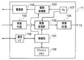
- FIG. 5 is a block configuration diagram of the processor 11.
- the processor 11 includes a control unit 101 having a central processing unit (hereinafter referred to as a CPU), an image processing unit 102, a drive control unit 103, a drive unit 104, a video front end unit (hereinafter referred to as a video FE unit) 105, a video back end.
- Unit hereinafter referred to as video BE unit
- TG timing generator
- communication I / F communication interface
- flash memory 109 which is a nonvolatile memory.
- the control unit 101 controls the entire processor 11 in order to realize various functions of the endoscope system 1 according to user operation instructions.
- the various functions include a white balance adjustment function.
- the control unit 101 performs processing for controlling the image processing unit 102 and the drive control unit 103 based on various adjustment parameters obtained as a result of the white balance processing.
- the video FE unit 105 receives an image signal of an endoscopic image received via the connector unit 12 a of the light source device 12 and supplies the image signal to the image processing unit 102.
- the image processing unit 102 performs predetermined image processing on the image signal from the video FE unit 105 using various adjustment parameters from the control unit 101, and outputs the image processed image signal to the video BE unit 106.
- the video BE unit 106 generates an analog image signal and outputs it to the monitor 13.
- the drive control unit 103 uses the various adjustment parameters from the control unit 101 to generate a drive clock signal for each imaging element of the endoscope and outputs the drive clock signal via the drive unit 104.
- the TG 107 generates various timing signals for the image processing unit 102 and the drive control unit 103.
- the image processing unit 102 and the drive control unit 103 each generate an image signal and a drive pulse signal using various timing signals from the TG 107.
- the communication I / F 108 is an interface circuit for communication of various data such as operation signals, endoscope ID information, adapter ID information, and adjustment parameters.
- the control unit 101 performs data communication with the endoscope 21 and the adapter 41 via the communication I / F 108.
- the flash memory 109 is a table for storing adjusted endoscope information related to the first type endoscope 21, and adjusted related to the combination of the second type endoscope 31 and the adapter 41. And a table for storing combination information. The configuration of these tables will be described later.
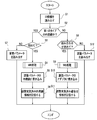
- FIG. 6 is a flowchart illustrating an example of the flow of the adjustment parameter acquisition and writing process of the processor 11.
- the process of FIG. 6 is executed.
- the processing of FIG. 6 is performed by the CPU of the control unit 101 executing a predetermined program stored in a ROM (not shown) or the like.
- the processor 11 can receive a signal from the connector portion 12 a of the light source device 12.
- the control unit 101 When the power of the processor 11 is turned on, the control unit 101 issues a predetermined command to determine whether the connector 21a is connected to the endoscope 21 or the adapter 41. Output and read the ID information (S1).
- the reading of the ID information includes a case of reading the endoscope ID information to the endoscope 21 and a case of reading the adapter ID information to the adapter 41 and the endoscope ID information of the endoscope 31.
- the endoscope 21 When the endoscope 21 receives a command for reading ID information from the processor 11, the endoscope 21 reads the endoscope ID information stored in the memory 25 a and transmits it to the processor 11.
- the FPGA 61 When the adapter 41 receives a command for reading ID information from the processor 11, the FPGA 61 transmits the adapter ID information stored in the memory 41 a to the processor 11 and identifies the connected endoscope 31.
- the resistance value of the resistor for use is read out through the buffer 73a, converted into a digital signal by the A / D converter 73b, and transmitted to the processor 11 as endoscope ID information of the endoscope 31.
- the endoscope ID information of the endoscope 31 is recorded in a ROM provided in the endoscope 31, and the endoscope ID of the endoscope 31 is provided by providing the adapter 41 with a means for reading the information in the ROM. Information may be obtained.
- the control unit 101 of the processor 11 determines whether the first type endoscope 21 is connected to the connector unit 12a or the second type endoscope 31 is the adapter 41. It is determined whether it is connected via (S2). That is, when only the endoscope ID information is received, it is determined that the first type endoscope 21 is connected, and when both the adapter ID information and the endoscope ID information are received, It is determined that the two types of endoscope 31 are connected.
- a code indicating that only the endoscope is connected to each of the endoscope 21 and the adapter 41 and a code indicating that the endoscope and the adapter are connected are stored. It may be determined whether the endoscope being used is the first type endoscope 21 or the second type endoscope 31.
- the control unit 101 When the endoscope 21 is an endoscope that is connected for the first time or an endoscope that has not yet been subjected to white balance adjustment (S3: YES), the control unit 101 performs white balance (WB) processing. (S4). In the white balance processing, white balance adjustment, inter-channel gain adjustment, and the like are performed. This white balance process is the same as the conventional process. Various adjustment parameters obtained in the white balance process include a coefficient for white balance adjustment, a coefficient for gain adjustment between channels, and the like.
- control unit 101 writes various adjustment parameters obtained as a result of the white balance process to the flash memory 25a of the endoscope 21 (S5), and sets the endoscope ID information as adjusted endoscope information.
- the data is written and stored in a table TBL1 (described later) in the flash memory 109 (S6), and this process is terminated.
- the adjustment parameter is read from the flash memory 25a of the endoscope 21 (S7), and this process is terminated.
- the processor 11 uses the various adjustment parameters obtained by the white balance process (S4) or read from the flash memory 25a (S7). Since the imaging device is driven and the image processing for the image signal can be appropriately executed, the endoscope system 1 shifts to a state in which the user can perform an endoscopic examination using the endoscope system 1.
- the endoscope 31 and the adapter 41 are the first combination based on the endoscope ID information and the adapter ID information. (S8). This determination is a combination of the endoscope 31 and the adapter 41 that has been connected to the flash memory 109 of the processor 11 in the past, and has been adjusted to indicate that the white balance adjustment has been performed. Since combination information is stored, it is performed based on the information. The adjusted combination information stored in the flash memory 109 will be described later.
- the adjustment parameters related to the combination are read from the flash memory 41b of the adapter 41 (S12), and this process is terminated.
- the adapter 41 when receiving an adjustment parameter read command from the processor 11, the adapter 41 reads the adjustment parameter corresponding to the endoscope ID information of the connected endoscope 31, and transmits it to the processor 11.
- the processor 11 uses the various adjustment parameters obtained by the white balance processing (S9) or read out from the flash memory 41b (S12) to drive the image sensor 32a and image. Since the image processing for the signal can be appropriately executed, the endoscope system 1 shifts to a state in which the user can perform an endoscopic examination using the endoscope system 1.
- the control unit 101 refers to the table TBL2 of the flash memory 109 to determine whether or not there is adjustment combination information about the combination of the endoscope identification information and the adapter identification information received from the adapter 41, and has been adjusted.
- the combination information does not exist, a predetermined adjustment process is executed, the adjustment parameters obtained by the execution are stored in the flash memory 41b of the adapter 41, and the adjustment relating to the combination of the endoscope identification information and the adapter identification information
- Two pieces of table data are stored in the flash memory 109 of the processor 11.
- One is a table for storing adjusted endoscope information related to the first type endoscope 21, and the other
- These are tables for storing adjusted combination information relating to the combination of the endoscope 31 and the adapter 41 of the second type.
- FIG. 7 is a diagram showing a configuration of a table for storing adjusted endoscope information related to the first type endoscope 21.
- the table TBL1 executes the white balance process in S4, and stores endoscope ID information in which various adjustment parameters are written in the flash memory 25a of the endoscope 21 in S5.
- the control unit 101 When it is determined that the endoscope 21 is connected (S2: YES), the control unit 101 refers to the table TBL1 and checks the presence / absence of the endoscope ID information of the endoscope 21. If it is checked and the endoscope ID information is present in the table TBL1, it is determined that the endoscope 21 has already been subjected to the white balance process. If it is checked and there is no endoscope ID information in the table TBL1, it is determined that the endoscope 21 is connected and used for the first time.
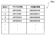
- FIG. 8 is a diagram showing a configuration of a table for storing adjusted combination information related to the second type endoscope 31 and the adapter 41.
- the table TBL2 performs white balance processing in S9, and stores combination information of the endoscope ID information of the endoscope 31 and the adapter ID information of the adapter 41 in which the adjustment parameters are written in the flash memory 41b of the adapter 41 in S10. To do.
- the controller 101 determines that the endoscope 31 is connected via the adapter 41 (S2: NO)
- the controller 101 refers to the table TBL2 and the adapter ID information of the adapter 41 and the endoscope 31. Check whether there is any combination of endoscope ID information. If it is checked and the table TBL2 has a combination of the adapter ID information and the endoscope ID information, it is determined that the combination of the adapter 41 and the endoscope 31 that have already executed the white balance adjustment. . If the combination is not found in the table TBL2, it is determined that the combination of the adapter 41 and the endoscope 31 to be used for the first time is used. Therefore, the table TBL2 constitutes an adjusted combination information storage unit that stores adjusted combination information indicating whether or not predetermined adjustment processing has been performed in the combination of endoscope identification information and adapter identification information.
- the user can use the adapter 41 with the same usability as when using the endoscope 21 that stores the various adjustment parameters such as the white balance coefficient in the nonvolatile memory. It is possible to use the endoscope 31 in which such a memory is not inserted.
- the adapter 41 described above has a light guide 42 and a contact portion 43 so that the adapter main body is compatible with the light source device 12 corresponding to the first type endoscope 21.
- the processor 11 corresponds to the first type endoscope 21, but the light source device may be used in a combination that is a device corresponding to the second type endoscope 31.
- the adapter may only be connected to the electric connector of the endoscope 31 of the second type.
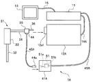
- FIG. 9 is a diagram for explaining a configuration example of the endoscope system 1A using the adapter 41A according to the present modification.
- FIG. 10 is a perspective view of the adapter 41A.
- the same components as those in the above-described embodiment are denoted by the same reference numerals and description thereof is omitted.
- the endoscope system 1A includes a processor 11, a light source device 12A, an adapter 41A, and a second type endoscope 31.
- the light source device 12A is a light source device corresponding to the endoscope 31, and the light guide 36 of the endoscope 31 can be attached to the connector portion 12a1.
- the connector 12a1 supplies illumination light to the light guide 36.
- the light source device 12A is connected to the processor 11 by a cable 14A and can receive a control signal from the processor 11.
- the adapter 41A has a box shape and can be connected to the connector 35 of the endoscope 31 by a cable 45A.
- the adapter 41A can be connected to the processor 11 via a cable 45B extending from the adapter 41A.
- the adapter 41A includes a circuit board 51.
- the cable 45A has a connector 44a at one end, and the contact portion of the connector 44a is electrically connected to the adapter 41A and the contact portion by inserting the connector 44a into the insertion port 41A1 of the adapter 41A.
- the connector 35a and the circuit board 51 are electrically connected.
- the processor 11 and the endoscope 13 can exchange electrical signals via the adapter 41A, and the circuit board 51 receives various commands from the processor 11 and endoscope ID information of the endoscope 31. Etc. can be transmitted. Further, the processor 11 can supply a drive signal to the image sensor 32 a and receive an image signal from the image sensor 32 a via the circuit board 51.
- the user can connect the second type endoscope 31 to the first type endoscope 31. It can be used with the same ease of use as an endoscope.
- the user can store the endoscope connected to the processor using the adapter in the nonvolatile memory that incorporates various adjustment parameters.
- An endoscope adapter, an endoscope processor, and an endoscope system that can be used with the same usability as when a mirror is used can be realized.
- the present invention is not limited to the above-described embodiments, and various changes and modifications can be made without departing from the scope of the present invention.
Abstract
Priority Applications (4)
| Application Number | Priority Date | Filing Date | Title |
|---|---|---|---|
| EP11862001.2A EP2626000B1 (fr) | 2011-03-29 | 2011-11-17 | Adaptateur d'endoscope, processeur d'endoscope et système d'endoscope |
| CN201180042793.8A CN103079450B (zh) | 2011-03-29 | 2011-11-17 | 内窥镜用适配器、内窥镜用处理器和内窥镜系统 |
| JP2012552601A JP5185477B2 (ja) | 2011-03-29 | 2011-11-17 | 内視鏡用アダプタ、内視鏡用プロセッサ及び内視鏡システム |
| US13/688,870 US8525875B2 (en) | 2011-03-29 | 2012-11-29 | Adapter for endoscope, processor for endoscope and endoscope system |
Applications Claiming Priority (2)
| Application Number | Priority Date | Filing Date | Title |
|---|---|---|---|
| JP2011073370 | 2011-03-29 | ||
| JP2011-073370 | 2011-03-29 |
Related Child Applications (1)
| Application Number | Title | Priority Date | Filing Date |
|---|---|---|---|
| US13/688,870 Continuation US8525875B2 (en) | 2011-03-29 | 2012-11-29 | Adapter for endoscope, processor for endoscope and endoscope system |
Publications (1)
| Publication Number | Publication Date |
|---|---|
| WO2012132096A1 true WO2012132096A1 (fr) | 2012-10-04 |
Family
ID=46929895
Family Applications (1)
| Application Number | Title | Priority Date | Filing Date |
|---|---|---|---|
| PCT/JP2011/076509 WO2012132096A1 (fr) | 2011-03-29 | 2011-11-17 | Adaptateur d'endoscope, processeur d'endoscope et système d'endoscope |
Country Status (5)
| Country | Link |
|---|---|
| US (1) | US8525875B2 (fr) |
| EP (1) | EP2626000B1 (fr) |
| JP (1) | JP5185477B2 (fr) |
| CN (1) | CN103079450B (fr) |
| WO (1) | WO2012132096A1 (fr) |
Cited By (7)
| Publication number | Priority date | Publication date | Assignee | Title |
|---|---|---|---|---|
| JP2014140749A (ja) * | 2013-01-24 | 2014-08-07 | Covidien Lp | 電気機械的外科手術システムとの使用のためのインテリジェントアダプターアセンブリ |
| JP2014226196A (ja) * | 2013-05-20 | 2014-12-08 | Hoya株式会社 | 内視鏡用光源装置および電子内視鏡システム |
| WO2015190147A1 (fr) * | 2014-06-11 | 2015-12-17 | オリンパス株式会社 | Dispositif de sortie de signal d'horloge, dispositif de commande, et endoscope |
| WO2016174902A1 (fr) * | 2015-04-30 | 2016-11-03 | ソニー・オリンパスメディカルソリューションズ株式会社 | Dispositif de relais et dispositif médical |
| JP6161841B1 (ja) * | 2016-03-07 | 2017-07-12 | オリンパス株式会社 | 内視鏡システム及び内視鏡 |
| WO2017154244A1 (fr) * | 2016-03-07 | 2017-09-14 | オリンパス株式会社 | Système d'endoscope, et endoscope |
| JP6301046B1 (ja) * | 2016-09-29 | 2018-03-28 | オリンパス株式会社 | ワイヤレス内視鏡装置 |
Families Citing this family (46)
| Publication number | Priority date | Publication date | Assignee | Title |
|---|---|---|---|---|
| US10524645B2 (en) | 2009-06-18 | 2020-01-07 | Endochoice, Inc. | Method and system for eliminating image motion blur in a multiple viewing elements endoscope |
| US9474440B2 (en) | 2009-06-18 | 2016-10-25 | Endochoice, Inc. | Endoscope tip position visual indicator and heat management system |
| JP5085807B2 (ja) * | 2010-10-08 | 2012-11-28 | オリンパスメディカルシステムズ株式会社 | 内視鏡 |
| US9706908B2 (en) | 2010-10-28 | 2017-07-18 | Endochoice, Inc. | Image capture and video processing systems and methods for multiple viewing element endoscopes |
| US10663714B2 (en) | 2010-10-28 | 2020-05-26 | Endochoice, Inc. | Optical system for an endoscope |
| US10517464B2 (en) | 2011-02-07 | 2019-12-31 | Endochoice, Inc. | Multi-element cover for a multi-camera endoscope |
| JP5838082B2 (ja) * | 2011-12-08 | 2015-12-24 | Hoya株式会社 | 内視鏡用中間モジュール |
| JP6000702B2 (ja) * | 2012-07-12 | 2016-10-05 | オリンパス株式会社 | 医療システム |
| JP6076139B2 (ja) * | 2013-03-04 | 2017-02-08 | Hoya株式会社 | 医療用光源装置 |
| US10595714B2 (en) | 2013-03-28 | 2020-03-24 | Endochoice, Inc. | Multi-jet controller for an endoscope |
| US9636003B2 (en) | 2013-06-28 | 2017-05-02 | Endochoice, Inc. | Multi-jet distributor for an endoscope |
| WO2014182723A1 (fr) | 2013-05-07 | 2014-11-13 | Endochoice, Inc. | Balance des blancs en enceinte destinée a être utilisée avec un endoscope a plusieurs éléments de visualisation |
| WO2014199980A1 (fr) * | 2013-06-12 | 2014-12-18 | オリンパスメディカルシステムズ株式会社 | Système d'endoscope |
| US10064541B2 (en) | 2013-08-12 | 2018-09-04 | Endochoice, Inc. | Endoscope connector cover detection and warning system |
| US9943218B2 (en) | 2013-10-01 | 2018-04-17 | Endochoice, Inc. | Endoscope having a supply cable attached thereto |
| US9968242B2 (en) | 2013-12-18 | 2018-05-15 | Endochoice, Inc. | Suction control unit for an endoscope having two working channels |
| WO2015112747A2 (fr) | 2014-01-22 | 2015-07-30 | Endochoice, Inc. | Systèmes et procédés de capture d'images et de traitement vidéo pour des endoscopes à plusieurs éléments de visualisation |
| WO2015194422A1 (fr) * | 2014-06-17 | 2015-12-23 | オリンパス株式会社 | Système d'endoscope et son procédé de réglage de balance des blancs |
| US20150374206A1 (en) * | 2014-06-26 | 2015-12-31 | Endochoice, Inc. | Methods and Systems for Managing Information Generated From and Transmitted To An Endoscopic System |
| CN111436896A (zh) | 2014-07-21 | 2020-07-24 | 恩多巧爱思股份有限公司 | 多焦、多相机内窥镜系统 |
| CN106687024B (zh) | 2014-08-29 | 2020-10-09 | 恩多巧爱思股份有限公司 | 改变内窥镜插入管的刚度的系统和方法 |
| CN106231987B (zh) * | 2014-10-07 | 2018-05-08 | 奥林巴斯株式会社 | 摄像装置、驱动信号调整方法及内窥镜系统 |
| EP3235241B1 (fr) | 2014-12-18 | 2023-09-06 | EndoChoice, Inc. | Système pour traiter des images vidéo générées par un endoscope à multiples éléments de visualisation |
| JP6348854B2 (ja) * | 2015-02-03 | 2018-06-27 | 富士フイルム株式会社 | 内視鏡用プロセッサ装置、内視鏡システム及び内視鏡システムの非接触給電方法 |
| US10376181B2 (en) | 2015-02-17 | 2019-08-13 | Endochoice, Inc. | System for detecting the location of an endoscopic device during a medical procedure |
| US10078207B2 (en) | 2015-03-18 | 2018-09-18 | Endochoice, Inc. | Systems and methods for image magnification using relative movement between an image sensor and a lens assembly |
| US10401611B2 (en) | 2015-04-27 | 2019-09-03 | Endochoice, Inc. | Endoscope with integrated measurement of distance to objects of interest |
| JP6340343B2 (ja) * | 2015-06-17 | 2018-06-06 | 富士フイルム株式会社 | コネクタ |
| JP2017006217A (ja) * | 2015-06-17 | 2017-01-12 | 富士フイルム株式会社 | コネクタ |
| US20170119474A1 (en) | 2015-10-28 | 2017-05-04 | Endochoice, Inc. | Device and Method for Tracking the Position of an Endoscope within a Patient's Body |
| JP6829926B2 (ja) * | 2015-11-11 | 2021-02-17 | Hoya株式会社 | 内視鏡装置 |
| EP3383244A4 (fr) | 2015-11-24 | 2019-07-17 | Endochoice, Inc. | Vannes d'air/eau et d'aspiration jetables pour un endoscope |
| JP6203467B1 (ja) * | 2015-12-14 | 2017-09-27 | オリンパス株式会社 | 光源装置 |
| EP3419497B1 (fr) | 2016-02-24 | 2022-06-01 | Endochoice, Inc. | Ensemble cartes de circuit imprimé pour endoscope à élément multivues utilisant des capteurs cmos |
| US10292570B2 (en) | 2016-03-14 | 2019-05-21 | Endochoice, Inc. | System and method for guiding and tracking a region of interest using an endoscope |
| CN109310408B (zh) | 2016-06-21 | 2021-11-23 | 安多卓思公司 | 具有与不同的视频数据信号源连接的多个连接接口的内窥镜系统 |
| WO2018061291A1 (fr) * | 2016-09-28 | 2018-04-05 | オリンパス株式会社 | Appareil médical et système d'appareil médical |
| WO2018070246A1 (fr) * | 2016-10-14 | 2018-04-19 | オリンパス株式会社 | Dispositif de traitement d'image |
| WO2018179966A1 (fr) * | 2017-03-29 | 2018-10-04 | 富士フイルム株式会社 | Dispositif de diagnostic par ultrasons |
| JP6930955B2 (ja) * | 2018-10-18 | 2021-09-01 | Hoya株式会社 | 中継アダプタ、内視鏡システム、および中継アダプタにおける信号処理方法 |
| DE102018133717A1 (de) * | 2018-12-31 | 2020-07-02 | Schölly Fiberoptic GmbH | Videobearbeitungsanordnung und Verfahren zur Videobearbeitung |
| JP7166957B2 (ja) * | 2019-02-27 | 2022-11-08 | オリンパス株式会社 | 内視鏡システム、プロセッサ、キャリブレーション装置、内視鏡 |
| CN110215180A (zh) * | 2019-07-04 | 2019-09-10 | 上海英诺伟医疗器械有限公司 | 硬性内窥镜装置 |
| CN111685883A (zh) * | 2019-07-23 | 2020-09-22 | 成都博恩思医学机器人有限公司 | 微创手术机器人的手术器械的自动识别与控制参数更新方法及装置 |
| WO2021077240A1 (fr) * | 2019-10-21 | 2021-04-29 | 新儿护科技医疗器材股份有限公司 | Hôte d'endoscope et dispositif endoscopique pour la détection intelligente d'organes |
| US10986321B1 (en) * | 2019-12-10 | 2021-04-20 | Arthrex, Inc. | Method and device for color correction of two or more self-illuminated camera systems |
Citations (6)
| Publication number | Priority date | Publication date | Assignee | Title |
|---|---|---|---|---|
| JPS6443227A (en) * | 1987-08-10 | 1989-02-15 | Olympus Optical Co | Electronic endoscopic apparatus |
| JPH05176886A (ja) | 1991-12-27 | 1993-07-20 | Fuji Photo Optical Co Ltd | 電子内視鏡装置用アダプタ |
| JPH07360A (ja) * | 1993-06-17 | 1995-01-06 | Olympus Optical Co Ltd | 撮像システム |
| JP2007244516A (ja) * | 2006-03-14 | 2007-09-27 | Olympus Medical Systems Corp | 変換アダプタ、医療システム、及び通信方法。 |
| JP2008245934A (ja) * | 2007-03-30 | 2008-10-16 | Hoya Corp | 信号変換アダプタおよび電子内視鏡システム |
| JP2011073370A (ja) | 2009-09-30 | 2011-04-14 | Fujifilm Corp | 平版印刷版原版、及びその製版方法 |
Family Cites Families (7)
| Publication number | Priority date | Publication date | Assignee | Title |
|---|---|---|---|---|
| US4816909A (en) | 1986-12-17 | 1989-03-28 | Olympus Optical Co., Ltd. | Video endoscope system for use with different sizes of solid state devices |
| JPH06114004A (ja) * | 1992-10-06 | 1994-04-26 | Fuji Photo Optical Co Ltd | 電子内視鏡のコネクタ抜け検出装置 |
| JP2001174744A (ja) * | 1999-10-06 | 2001-06-29 | Olympus Optical Co Ltd | 光走査プローブ装置 |
| CN100512744C (zh) * | 2004-03-02 | 2009-07-15 | 奥林巴斯株式会社 | 内窥镜 |
| JP2006055350A (ja) * | 2004-08-19 | 2006-03-02 | Olympus Corp | 内視鏡装置 |
| JP2007130085A (ja) * | 2005-11-08 | 2007-05-31 | Olympus Corp | 電子内視鏡 |
| JP4504339B2 (ja) * | 2006-09-22 | 2010-07-14 | オリンパスメディカルシステムズ株式会社 | 内視鏡装置 |
-
2011
- 2011-11-17 EP EP11862001.2A patent/EP2626000B1/fr not_active Not-in-force
- 2011-11-17 JP JP2012552601A patent/JP5185477B2/ja active Active
- 2011-11-17 WO PCT/JP2011/076509 patent/WO2012132096A1/fr active Application Filing
- 2011-11-17 CN CN201180042793.8A patent/CN103079450B/zh active Active
-
2012
- 2012-11-29 US US13/688,870 patent/US8525875B2/en active Active
Patent Citations (6)
| Publication number | Priority date | Publication date | Assignee | Title |
|---|---|---|---|---|
| JPS6443227A (en) * | 1987-08-10 | 1989-02-15 | Olympus Optical Co | Electronic endoscopic apparatus |
| JPH05176886A (ja) | 1991-12-27 | 1993-07-20 | Fuji Photo Optical Co Ltd | 電子内視鏡装置用アダプタ |
| JPH07360A (ja) * | 1993-06-17 | 1995-01-06 | Olympus Optical Co Ltd | 撮像システム |
| JP2007244516A (ja) * | 2006-03-14 | 2007-09-27 | Olympus Medical Systems Corp | 変換アダプタ、医療システム、及び通信方法。 |
| JP2008245934A (ja) * | 2007-03-30 | 2008-10-16 | Hoya Corp | 信号変換アダプタおよび電子内視鏡システム |
| JP2011073370A (ja) | 2009-09-30 | 2011-04-14 | Fujifilm Corp | 平版印刷版原版、及びその製版方法 |
Non-Patent Citations (1)
| Title |
|---|
| See also references of EP2626000A4 |
Cited By (11)
| Publication number | Priority date | Publication date | Assignee | Title |
|---|---|---|---|---|
| JP2014140749A (ja) * | 2013-01-24 | 2014-08-07 | Covidien Lp | 電気機械的外科手術システムとの使用のためのインテリジェントアダプターアセンブリ |
| JP2014226196A (ja) * | 2013-05-20 | 2014-12-08 | Hoya株式会社 | 内視鏡用光源装置および電子内視鏡システム |
| WO2015190147A1 (fr) * | 2014-06-11 | 2015-12-17 | オリンパス株式会社 | Dispositif de sortie de signal d'horloge, dispositif de commande, et endoscope |
| JPWO2015190147A1 (ja) * | 2014-06-11 | 2017-04-20 | オリンパス株式会社 | クロック信号出力装置、制御装置および内視鏡 |
| WO2016174902A1 (fr) * | 2015-04-30 | 2016-11-03 | ソニー・オリンパスメディカルソリューションズ株式会社 | Dispositif de relais et dispositif médical |
| JPWO2016174902A1 (ja) * | 2015-04-30 | 2018-02-22 | ソニー・オリンパスメディカルソリューションズ株式会社 | 中継デバイス及び医療機器 |
| US10567706B2 (en) | 2015-04-30 | 2020-02-18 | Sony Olympus Medical Solutions Inc. | Relay device and medical device |
| JP6161841B1 (ja) * | 2016-03-07 | 2017-07-12 | オリンパス株式会社 | 内視鏡システム及び内視鏡 |
| WO2017154244A1 (fr) * | 2016-03-07 | 2017-09-14 | オリンパス株式会社 | Système d'endoscope, et endoscope |
| US10716459B2 (en) | 2016-03-07 | 2020-07-21 | Olympus Corporation | Endoscope system and endoscope |
| JP6301046B1 (ja) * | 2016-09-29 | 2018-03-28 | オリンパス株式会社 | ワイヤレス内視鏡装置 |
Also Published As
| Publication number | Publication date |
|---|---|
| EP2626000A1 (fr) | 2013-08-14 |
| EP2626000B1 (fr) | 2015-07-08 |
| JPWO2012132096A1 (ja) | 2014-07-24 |
| CN103079450B (zh) | 2015-05-13 |
| JP5185477B2 (ja) | 2013-04-17 |
| US8525875B2 (en) | 2013-09-03 |
| EP2626000A4 (fr) | 2013-11-06 |
| CN103079450A (zh) | 2013-05-01 |
| US20130141557A1 (en) | 2013-06-06 |
Similar Documents
| Publication | Publication Date | Title |
|---|---|---|
| JP5185477B2 (ja) | 内視鏡用アダプタ、内視鏡用プロセッサ及び内視鏡システム | |
| JP4598679B2 (ja) | 電動湾曲内視鏡装置 | |
| US10149609B2 (en) | Signal processing device and endoscope system | |
| WO2012121127A1 (fr) | Dispositif d'endoscope électronique, processeur d'endoscope électronique, dispositif de source de lumière, et système d'endoscope électronique | |
| JP6017739B1 (ja) | 走査型内視鏡装置 | |
| JP5384887B2 (ja) | 内視鏡装置 | |
| JP2007130132A (ja) | 内視鏡挿入部形状把握システム | |
| JP2008245934A (ja) | 信号変換アダプタおよび電子内視鏡システム | |
| US20170086662A1 (en) | Scanning endoscope apparatus | |
| JP6381123B2 (ja) | 光走査型観察システム | |
| EP1977695A1 (fr) | Système d'endoscope à ultrasons et procédé de contrôle de système d'endoscope à ultrasons | |
| WO2019171614A1 (fr) | Endoscope et procédé de fonctionnement d'endoscope | |
| JP5361296B2 (ja) | 内視鏡装置 | |
| JP2019141510A (ja) | 内視鏡システム | |
| JP4708962B2 (ja) | 内視鏡挿入部形状把握システム | |
| JP6257174B2 (ja) | 内視鏡装置 | |
| JP6535143B1 (ja) | 内視鏡および内視鏡の作動方法 | |
| WO2019111403A1 (fr) | Système d'endoscope | |
| WO2017002649A1 (fr) | Système d'endoscope | |
| JP2001000386A (ja) | 内視鏡装置 | |
| JP5214506B2 (ja) | 内視鏡装置 | |
| JP2016116750A (ja) | 内視鏡システム | |
| JP6238861B2 (ja) | 内視鏡用制御装置及び内視鏡システム | |
| WO2017002412A1 (fr) | Système endoscopique | |
| JP2015181586A (ja) | 内視鏡装置、カメラヘッド、及び制御装置 |
Legal Events
| Date | Code | Title | Description |
|---|---|---|---|
| WWE | Wipo information: entry into national phase |
Ref document number: 201180042793.8 Country of ref document: CN |
|
| ENP | Entry into the national phase |
Ref document number: 2012552601 Country of ref document: JP Kind code of ref document: A |
|
| 121 | Ep: the epo has been informed by wipo that ep was designated in this application |
Ref document number: 11862001 Country of ref document: EP Kind code of ref document: A1 |
|
| WWE | Wipo information: entry into national phase |
Ref document number: 2011862001 Country of ref document: EP |
|
| NENP | Non-entry into the national phase |
Ref country code: DE |