WO2012131888A1 - 半導体結晶製造装置用排気通路のクリーニング装置及びそのクリーニング方法 - Google Patents
半導体結晶製造装置用排気通路のクリーニング装置及びそのクリーニング方法 Download PDFInfo
- Publication number
- WO2012131888A1 WO2012131888A1 PCT/JP2011/057739 JP2011057739W WO2012131888A1 WO 2012131888 A1 WO2012131888 A1 WO 2012131888A1 JP 2011057739 W JP2011057739 W JP 2011057739W WO 2012131888 A1 WO2012131888 A1 WO 2012131888A1
- Authority
- WO
- WIPO (PCT)
- Prior art keywords
- cleaning
- exhaust passage
- chamber
- semiconductor crystal
- crystal manufacturing
- Prior art date
- Legal status (The legal status is an assumption and is not a legal conclusion. Google has not performed a legal analysis and makes no representation as to the accuracy of the status listed.)
- Ceased
Links
Images



Classifications
-
- C—CHEMISTRY; METALLURGY
- C30—CRYSTAL GROWTH
- C30B—SINGLE-CRYSTAL GROWTH; UNIDIRECTIONAL SOLIDIFICATION OF EUTECTIC MATERIAL OR UNIDIRECTIONAL DEMIXING OF EUTECTOID MATERIAL; REFINING BY ZONE-MELTING OF MATERIAL; PRODUCTION OF A HOMOGENEOUS POLYCRYSTALLINE MATERIAL WITH DEFINED STRUCTURE; SINGLE CRYSTALS OR HOMOGENEOUS POLYCRYSTALLINE MATERIAL WITH DEFINED STRUCTURE; AFTER-TREATMENT OF SINGLE CRYSTALS OR A HOMOGENEOUS POLYCRYSTALLINE MATERIAL WITH DEFINED STRUCTURE; APPARATUS THEREFOR
- C30B35/00—Apparatus not otherwise provided for, specially adapted for the growth, production or after-treatment of single crystals or of a homogeneous polycrystalline material with defined structure
- C30B35/007—Apparatus for preparing, pre-treating the source material to be used for crystal growth
-
- C—CHEMISTRY; METALLURGY
- C30—CRYSTAL GROWTH
- C30B—SINGLE-CRYSTAL GROWTH; UNIDIRECTIONAL SOLIDIFICATION OF EUTECTIC MATERIAL OR UNIDIRECTIONAL DEMIXING OF EUTECTOID MATERIAL; REFINING BY ZONE-MELTING OF MATERIAL; PRODUCTION OF A HOMOGENEOUS POLYCRYSTALLINE MATERIAL WITH DEFINED STRUCTURE; SINGLE CRYSTALS OR HOMOGENEOUS POLYCRYSTALLINE MATERIAL WITH DEFINED STRUCTURE; AFTER-TREATMENT OF SINGLE CRYSTALS OR A HOMOGENEOUS POLYCRYSTALLINE MATERIAL WITH DEFINED STRUCTURE; APPARATUS THEREFOR
- C30B15/00—Single-crystal growth by pulling from a melt, e.g. Czochralski method
-
- C—CHEMISTRY; METALLURGY
- C30—CRYSTAL GROWTH
- C30B—SINGLE-CRYSTAL GROWTH; UNIDIRECTIONAL SOLIDIFICATION OF EUTECTIC MATERIAL OR UNIDIRECTIONAL DEMIXING OF EUTECTOID MATERIAL; REFINING BY ZONE-MELTING OF MATERIAL; PRODUCTION OF A HOMOGENEOUS POLYCRYSTALLINE MATERIAL WITH DEFINED STRUCTURE; SINGLE CRYSTALS OR HOMOGENEOUS POLYCRYSTALLINE MATERIAL WITH DEFINED STRUCTURE; AFTER-TREATMENT OF SINGLE CRYSTALS OR A HOMOGENEOUS POLYCRYSTALLINE MATERIAL WITH DEFINED STRUCTURE; APPARATUS THEREFOR
- C30B29/00—Single crystals or homogeneous polycrystalline material with defined structure characterised by the material or by their shape
- C30B29/02—Elements
- C30B29/06—Silicon
-
- C—CHEMISTRY; METALLURGY
- C30—CRYSTAL GROWTH
- C30B—SINGLE-CRYSTAL GROWTH; UNIDIRECTIONAL SOLIDIFICATION OF EUTECTIC MATERIAL OR UNIDIRECTIONAL DEMIXING OF EUTECTOID MATERIAL; REFINING BY ZONE-MELTING OF MATERIAL; PRODUCTION OF A HOMOGENEOUS POLYCRYSTALLINE MATERIAL WITH DEFINED STRUCTURE; SINGLE CRYSTALS OR HOMOGENEOUS POLYCRYSTALLINE MATERIAL WITH DEFINED STRUCTURE; AFTER-TREATMENT OF SINGLE CRYSTALS OR A HOMOGENEOUS POLYCRYSTALLINE MATERIAL WITH DEFINED STRUCTURE; APPARATUS THEREFOR
- C30B35/00—Apparatus not otherwise provided for, specially adapted for the growth, production or after-treatment of single crystals or of a homogeneous polycrystalline material with defined structure
-
- C—CHEMISTRY; METALLURGY
- C30—CRYSTAL GROWTH
- C30B—SINGLE-CRYSTAL GROWTH; UNIDIRECTIONAL SOLIDIFICATION OF EUTECTIC MATERIAL OR UNIDIRECTIONAL DEMIXING OF EUTECTOID MATERIAL; REFINING BY ZONE-MELTING OF MATERIAL; PRODUCTION OF A HOMOGENEOUS POLYCRYSTALLINE MATERIAL WITH DEFINED STRUCTURE; SINGLE CRYSTALS OR HOMOGENEOUS POLYCRYSTALLINE MATERIAL WITH DEFINED STRUCTURE; AFTER-TREATMENT OF SINGLE CRYSTALS OR A HOMOGENEOUS POLYCRYSTALLINE MATERIAL WITH DEFINED STRUCTURE; APPARATUS THEREFOR
- C30B29/00—Single crystals or homogeneous polycrystalline material with defined structure characterised by the material or by their shape
- C30B29/10—Inorganic compounds or compositions
- C30B29/40—AIIIBV compounds wherein A is B, Al, Ga, In or Tl and B is N, P, As, Sb or Bi
-
- C—CHEMISTRY; METALLURGY
- C30—CRYSTAL GROWTH
- C30B—SINGLE-CRYSTAL GROWTH; UNIDIRECTIONAL SOLIDIFICATION OF EUTECTIC MATERIAL OR UNIDIRECTIONAL DEMIXING OF EUTECTOID MATERIAL; REFINING BY ZONE-MELTING OF MATERIAL; PRODUCTION OF A HOMOGENEOUS POLYCRYSTALLINE MATERIAL WITH DEFINED STRUCTURE; SINGLE CRYSTALS OR HOMOGENEOUS POLYCRYSTALLINE MATERIAL WITH DEFINED STRUCTURE; AFTER-TREATMENT OF SINGLE CRYSTALS OR A HOMOGENEOUS POLYCRYSTALLINE MATERIAL WITH DEFINED STRUCTURE; APPARATUS THEREFOR
- C30B29/00—Single crystals or homogeneous polycrystalline material with defined structure characterised by the material or by their shape
- C30B29/10—Inorganic compounds or compositions
- C30B29/40—AIIIBV compounds wherein A is B, Al, Ga, In or Tl and B is N, P, As, Sb or Bi
- C30B29/42—Gallium arsenide
-
- C—CHEMISTRY; METALLURGY
- C30—CRYSTAL GROWTH
- C30B—SINGLE-CRYSTAL GROWTH; UNIDIRECTIONAL SOLIDIFICATION OF EUTECTIC MATERIAL OR UNIDIRECTIONAL DEMIXING OF EUTECTOID MATERIAL; REFINING BY ZONE-MELTING OF MATERIAL; PRODUCTION OF A HOMOGENEOUS POLYCRYSTALLINE MATERIAL WITH DEFINED STRUCTURE; SINGLE CRYSTALS OR HOMOGENEOUS POLYCRYSTALLINE MATERIAL WITH DEFINED STRUCTURE; AFTER-TREATMENT OF SINGLE CRYSTALS OR A HOMOGENEOUS POLYCRYSTALLINE MATERIAL WITH DEFINED STRUCTURE; APPARATUS THEREFOR
- C30B29/00—Single crystals or homogeneous polycrystalline material with defined structure characterised by the material or by their shape
- C30B29/10—Inorganic compounds or compositions
- C30B29/46—Sulfur-, selenium- or tellurium-containing compounds
- C30B29/48—AIIBVI compounds wherein A is Zn, Cd or Hg, and B is S, Se or Te
-
- Y—GENERAL TAGGING OF NEW TECHNOLOGICAL DEVELOPMENTS; GENERAL TAGGING OF CROSS-SECTIONAL TECHNOLOGIES SPANNING OVER SEVERAL SECTIONS OF THE IPC; TECHNICAL SUBJECTS COVERED BY FORMER USPC CROSS-REFERENCE ART COLLECTIONS [XRACs] AND DIGESTS
- Y10—TECHNICAL SUBJECTS COVERED BY FORMER USPC
- Y10T—TECHNICAL SUBJECTS COVERED BY FORMER US CLASSIFICATION
- Y10T117/00—Single-crystal, oriented-crystal, and epitaxy growth processes; non-coating apparatus therefor
-
- Y—GENERAL TAGGING OF NEW TECHNOLOGICAL DEVELOPMENTS; GENERAL TAGGING OF CROSS-SECTIONAL TECHNOLOGIES SPANNING OVER SEVERAL SECTIONS OF THE IPC; TECHNICAL SUBJECTS COVERED BY FORMER USPC CROSS-REFERENCE ART COLLECTIONS [XRACs] AND DIGESTS
- Y10—TECHNICAL SUBJECTS COVERED BY FORMER USPC
- Y10T—TECHNICAL SUBJECTS COVERED BY FORMER US CLASSIFICATION
- Y10T117/00—Single-crystal, oriented-crystal, and epitaxy growth processes; non-coating apparatus therefor
- Y10T117/10—Apparatus
Definitions
- the present invention relates to an apparatus for cleaning an exhaust passage used in an apparatus for manufacturing a semiconductor crystal such as silicon single crystal, silicon polycrystal, GaAs single crystal, and GaAs polycrystal, and a method for cleaning the exhaust passage.
- a semiconductor crystal such as silicon single crystal, silicon polycrystal, GaAs single crystal, and GaAs polycrystal
- a vacuum pump is configured such that an inert gas supplied to the puller is sucked through an exhaust pipe connected to a single crystal puller, and a cleaning outlet provided in the exhaust pipe One end of the cleaning pipe is connected to the other end of the cleaning pipe, and a cleaning suction pump is connected to the other end of the cleaning pipe. Further, the cleaning suction pump sucks the inert gas or the atmosphere in the exhaust pipe in the open state in the puller.
- a cleaning device for an inert gas exhaust system of a single crystal puller configured as described above is disclosed (for example, see Patent Document 1).
- a cleaning powder separator is provided in a cleaning pipe between the cleaning outlet and the suction pump, and the suction flow rate of the suction pump is adjustable.
- the cleaning device configured as described above, at the time of cleaning the inert gas exhaust system of the single crystal puller, after the puller is opened to the atmosphere, one end of the cleaning pipe is connected to the cleaning outlet, and the suction for cleaning is performed. Drive the pump. At this time, since the introduction flow rate of the air into the exhaust pipe of the suction pump is increased stepwise or gradually, first, the dust accumulated in the exhaust pipe etc. is gradually burned, and after these dusts are completely burned, the exhaust pipe etc. And separated and collected by a cleaning powder separator. As a result, almost all of the dust accumulated in the exhaust pipe can be easily and safely removed in a short time without a sudden increase in temperature and pressure in the exhaust pipe.
- the flow rate of air introduced into the exhaust pipe is increased stepwise or gradually in order to suppress rapid combustion of dust accumulated in the exhaust pipe.
- the air introduction flow rate into the exhaust pipe is increased stepwise or gradually, and the air introduction flow rate into the exhaust pipe becomes relatively large, then the air introduction flow rate is suddenly increased. Since there is not much difference, a part of the completely burned dust remains on the inner wall of the exhaust pipe without being separated from the inner wall of the exhaust pipe. For this reason, if the silicon single crystal pulling process is performed a plurality of times, the amount of dust deposited on the inner wall of the exhaust pipe increases, so it is necessary to periodically clean the exhaust pipe every time a predetermined number of pulling processes are performed. . During the regular cleaning of the exhaust pipe, the exhaust pipe has to be removed from the chamber, and there has been a problem that the cleaning operation takes a long time.
- the silicon single crystal pulling process is performed a plurality of times without cleaning the exhaust pipe when the amount of accumulated dust on the inner wall of the exhaust pipe increases. If the process proceeds to the next pulling process of the silicon single crystal, the pressure control in the chamber becomes difficult and the pressure fluctuation in the chamber becomes large, so that the pulling condition of the silicon single crystal is adversely affected or the exhaust pipe is exhausted. When the dust accumulated on the inner wall of the steel plate is unintentionally separated, there is a problem of damaging the vacuum pump or the like.
- An object of the present invention is for a semiconductor crystal manufacturing apparatus that can efficiently remove dust accumulated in an exhaust passage, thereby shortening the cleaning time of the exhaust passage and suppressing pressure fluctuations in the chamber during manufacture of the semiconductor crystal.
- An object of the present invention is to provide an exhaust passage cleaning device and a cleaning method therefor.
- a first aspect of the present invention is an exhaust for a semiconductor crystal manufacturing apparatus that removes dust accumulated in an exhaust passage provided in a chamber for exhausting a gas in the chamber of the semiconductor crystal manufacturing apparatus by suction from outside the chamber.
- the passage cleaning device includes a cleaning on-off valve that is detachably attached to the opening of the exhaust passage facing the chamber and intermittently opens and closes the opening in the suction state, and a valve driving unit that drives the cleaning on-off valve. It is characterized by that.
- a second aspect of the present invention is an invention based on the first aspect, and further includes an insertion cylinder that has a flange portion that contacts the end face of the opening portion and can be inserted into the opening portion, and is attached to the flange portion for cleaning. And a valve holder for holding the on-off valve.
- the third aspect of the present invention is an invention based on the second aspect, and further is characterized in that a valve holder is provided extending in a direction away from the insertion tube, and a handle is attached to the tip.
- the fourth aspect of the present invention is an invention based on the second aspect, and is characterized in that a hook is attached to the valve holder.
- a fifth aspect of the present invention is an invention based on the first aspect, and is characterized in that the valve driving means is a fluid pressure cylinder.
- the sixth aspect of the present invention is the invention based on the first or fifth aspect, and further characterized in that the intermittent opening / closing cycle of the opening by the valve driving means is 1 to 30 seconds.
- an exhaust for a semiconductor crystal manufacturing apparatus that removes dust accumulated in an exhaust passage provided in a chamber for exhausting a gas in the chamber of the semiconductor crystal manufacturing apparatus by suction from outside the chamber.
- the passage cleaning method by opening the opening of the exhaust passage facing the chamber and introducing the atmosphere into the exhaust passage, and closing the opening and sucking the air introduced into the exhaust passage.
- the air discharging step for discharging the air in the exhaust passage is performed once or repeated a plurality of times.
- the eighth aspect of the present invention is the invention based on the seventh aspect, and is characterized in that the repetition period of the air discharge step and the air introduction step is 1 to 30 seconds.
- the cleaning on-off valve removably attached to the opening of the exhaust passage facing the chamber intermittently opens and closes the opening in the suction state. Therefore, the pressure in the exhaust passage varies greatly. That is, when the on-off valve is closed, the exhaust passage becomes negative pressure, and when the on-off valve is opened, pressure fluctuation occurs in the exhaust passage so that the exhaust passage returns to atmospheric pressure. Thereby, dust accumulated in the exhaust passage can be efficiently removed. As a result, since it is not necessary to remove the exhaust pipe or the like when cleaning the exhaust passage, the cleaning time of the exhaust passage can be shortened.
- the insertion cylinder is inserted into the opening while the cleaning opening / closing valve is held by the valve holder attached to the flange of the insertion cylinder.
- the opening can be reliably opened and closed while the on-off valve is stable.
- the cleaning device even if the opening is formed on the bottom wall of the relatively deep chamber by grasping the handle at the tip of the valve holder and inserting the insertion tube into the opening,
- the insertion tube can be easily inserted into the opening.
- the opening is formed in the side wall near the bottom wall of the chamber having a relatively deep depth by holding the hook attached to the valve holder and inserting the insertion tube into the opening. Even if it is made, an insertion cylinder can be easily inserted in an opening part.
- an air introduction step for opening the exhaust passage opening to introduce the atmosphere into the exhaust passage, and an air discharge for closing the opening and discharging the air in the exhaust passage Since the process is performed once or repeated a plurality of times, dust accumulated in the exhaust passage can be efficiently removed when the pressure in the exhaust passage varies greatly. As a result, similarly to the above, it is not necessary to remove the exhaust pipe or the like when cleaning the exhaust passage, so that the exhaust passage cleaning time can be shortened. In addition, every time the semiconductor crystal manufacturing process is performed multiple times, all the dust accumulated in the exhaust passage can be removed periodically, so that pressure fluctuations in the chamber during semiconductor crystal production can be suppressed, and thus pressure fluctuations in the chamber can be suppressed. Thus, adverse effects on semiconductor manufacturing conditions can be prevented.
- FIG. 4 is a side view of the carriage showing a state where the cleaning device is placed on the carriage and a control box for controlling the cleaning on-off valve is placed on the carriage.
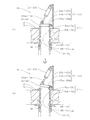
- It is principal part sectional drawing which shows the state which has inserted the insertion cylinder of the cleaning apparatus of 2nd Embodiment of this invention in the opening part, and has opened and closed the cleaning on-off valve with the air cylinder.
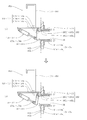
- It is principal part sectional drawing which shows the state which has inserted the insertion cylinder of the cleaning apparatus of 3rd Embodiment of this invention in the opening part, and has opened and closed the cleaning on-off valve with the air cylinder.
- the semiconductor crystal is a silicon single crystal
- the semiconductor crystal manufacturing apparatus 11 is a silicon single crystal pulling apparatus.
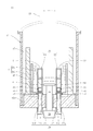
- the silicon single crystal pulling apparatus 11 includes a chamber 12 having a bottom wall 12 a and having an open upper end, and a casing 13 connected to the upper end of the chamber 12.
- a pulling means 18 for pulling up the silicon single crystal is provided at the upper end of the casing 13 (FIG. 3).
- the crucible 14 includes a bottomed cylindrical inner layer container 14a formed of quartz and storing a silicon melt, and a bottomed cylindrical outer layer container 14b formed of graphite and fitted to the outside of the inner layer container 14a. Become.
- the upper end of the shaft 19 is connected to the bottom of the outer layer container 14b, and a crucible driving means 20 for rotating and moving the crucible 14 through the shaft 19 is provided at the lower end of the shaft 19 (FIG. 2).
- first to fourth openings 12b to 12e facing the chamber 12 are formed on the bottom wall 12a of the chamber 12, respectively, and the first to fourth openings 12b to 12e extend in the vertical direction and extend to the bottom.
- the upper ends of the four first to fourth communication holes 12f to 12i penetrating the wall 12a are formed (FIGS. 1 and 2).
- the base ends of the four first to fourth exhaust pipes 21 to 24 are connected to the lower ends of the communication holes 12f to 12i, respectively, and the distal ends of the first to fourth exhaust pipes 21 to 24 are a single collective exhaust.
- Collectively connected to the proximal end side of the tube 26 (FIG. 3).
- a vacuum pump 27 is connected to the other end of the collective exhaust pipe 26.
- FIG. 3 denotes an intake pipe having one end connected to the upper surface of the casing 13.
- the other end of the intake pipe 28 is connected to a tank (not shown) in which an inert gas (Ar gas in this embodiment) is stored.
- An inert gas exhaust passage 29 is formed by the first to fourth openings 12b to 12e, the first to fourth communication holes 12f to 12i, the first to fourth exhaust pipes 21 to 24, and the collective exhaust pipe 26.
- the inert gas in the tank flows into the chamber 12 through the intake pipe 28 and the casing 13. After containing dust 36 such as SiO or SiO 2 in the chamber 12, the inert gas in the tank passes through the exhaust passage 29 and passes through the vacuum pump 27. Is configured to be discharged.
- the dust 36 such as SiO or SiO 2 contained in the inert gas is deposited on the inner wall of the exhaust passage 29, and the dust 36 deposited in the exhaust passage 29 is configured to be removed by the cleaning device 30.
- the cleaning device 30 is detachably attached to the first to fourth openings 12b to 12e of the exhaust passage 29 facing the chamber 12, and opens and closes the first to fourth openings 12b to 12e intermittently in the suction state.
- Disc-shaped first to fourth cleaning on-off valves 31 to 34 and first to fourth valve driving means 41 to 44 for driving the cleaning on-off valves 31 to 34, respectively, are provided.
- the cleaning device 30 includes first to fourth insertion cylinders 51 to 54 having first to fourth flange portions 51a to 54a, which are in contact with the end surfaces of the first to fourth openings 12b to 12e, respectively. Further, first to fourth valve holders 61 to 64 attached to the four flange portions 51a to 54a, respectively.
- the first to fourth valve driving means 41 to 44 are first to fourth air cylinders in this embodiment.
- the first to fourth insertion cylinders 51 to 54 are formed in a cylindrical shape that can be inserted into the first to fourth openings 12b to 12e, and these cylinder main bodies 51b.
- the first to fourth flange portions 51a to 54a are provided integrally with the cylinder main bodies 51b to 54b at one end of the cylinder main bodies 51b to 54b and have outer diameters larger than the outer diameters of the cylinder main bodies 51b to 54b. Further, the first to fourth valve holders 61 to 64 are provided with a plurality of pieces provided so as to stand upright from the first to fourth flange portions 51a to 54a and extend away from the first to fourth insertion cylinders 51 to 54.
- First to fourth air cylinders 41 to 44 are attached to the first to fourth holding plates 61b to 64b in a state where the first to fourth piston rods 41a to 44a protrude downward, and the first to fourth pistons
- the first to fourth cleaning on-off valves 31 to 34 are attached to the lower ends of the rods 41a to 44a. That is, the first to fourth cleaning on-off valves 31 to 34 are configured to be held by the first to fourth valve holders 61 to 64 via the first to fourth air cylinders 41 to 44, respectively.
- each of the first to fourth cleaning on-off valves 31 to 34 is formed with a small through hole or a slit on the bottom surface. This is because if the exhaust passage 29 is completely sealed, the air cylinders 41 to 44 may be overloaded.
- air inlets may be formed in the first to fourth holding plates 61b to 64b, respectively. This is because the air in the chamber 12 is smoothly introduced into the exhaust passage 29 from the introduction port.
- first to fourth handles 71 to 74 are attached to the upper ends of the first to fourth leg portions 61a to 64a of the first to fourth valve holders 61 to 64, respectively. Further, with the first to fourth insertion cylinders 51 to 54 inserted into the first to fourth openings 12b to 12e of the exhaust passage 29, the first to fourth air cylinders 41 to 44 are used for the first to fourth cleaning.
- the on-off valves 31 to 34 are driven to open and close the first to fourth openings 12b to 12e intermittently.
- the first to fourth openings 12b to 12e are intermittently opened and closed by the first to fourth air cylinders 41 to 44, that is, the first to fourth openings 12b are provided by the first to fourth cleaning on-off valves 31 to 34.
- the repetition period with the introducing step is set to 1 to 30 seconds, preferably 2 to 5 seconds.
- the intermittent opening / closing cycle of the first to fourth openings 12b to 12e by the first to fourth air cylinders 41 to 44 is limited to the range of 1 to 30 seconds. No pressure difference is generated in the exhaust passage 29 so that the dust 36 adhering to the 29 can be separated. If the pressure difference exceeds 30 seconds, the pressure difference in the exhaust passage 29 hardly changes and the efficiency of the cleaning operation of the exhaust passage 29 is reduced. Because it does.
- first to fourth cleaning on-off valves 31 to 34 are used for the first to fourth cleaning on-off valves 31 to 34 in a state where the pressure difference is such that the dust 36 adhering to the inner wall of the exhaust passage 29 can be separated, that is, the cleaning suction pump 93 is being driven.
- the first to fourth openings 12b to 12e are opened by the pressure (negative pressure) in the exhaust passage 29 when the fourth openings 12b to 12e are closed and the first to fourth cleaning on-off valves 31 to 34.
- the difference from the pressure (atmospheric pressure) in the exhaust passage is set to 0.02 MPa or more, preferably 0.1 MPa or more.
- the suction state of the exhaust passage 29 including the first to fourth openings 12b to 12e is generated by driving a suction pump 93 for cleaning the dust 36 and the cleaning device of the peeling device described later. Configured to be
- the first to fourth cleaning on-off valves 31 to 34, the first to fourth air cylinders 41 to 44, the first to fourth insertion cylinders 51 to 54, the first to fourth valve holders 61 to 64, and the first The first to fourth opening opening / closing means 81 to 84 are configured by the fourth handle.
- the first to fourth opening opening / closing means 81 to 84 are transported on a carriage 86 (FIG. 4).
- a control box 87 is placed on the carriage 86.
- the control box 87 accommodates a controller (not shown) that drives the first to fourth air cylinders 41 to 44 to control the opening and closing of the first to fourth cleaning on-off valves 31 to 34.
- the control box 87 also accommodates first to fourth solenoid valves (not shown) for switching the first to fourth piston rods 41a to 44a of the first to fourth air cylinders 41 to 44 so as to project and retract. .
- the first to fourth air cylinders 41 to 44 and the first to fourth solenoid valves are connected by an air tube (not shown).
- the first to fourth solenoid valves are electrically connected to the control output of the controller.
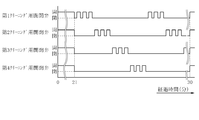
- the controller is provided with a memory (not shown), and the first to fourth cleaning on-off valves 31 to 34 are sequentially shifted three times at a time instead of simultaneously (the number of times of opening and closing is arbitrary).
- the time chart (FIG. 5) for controlling the first to fourth electromagnetic valves to open and close is stored as a map.
- a manual three-way switching valve 88 is provided in the collective exhaust pipe 26.
- the first port 88 a of the switching valve 88 is connected to the collective exhaust pipe 26 on the pulling device 11 side, and the second port 88 b is connected to the collective exhaust pipe 26 on the vacuum pump 27 side.
- the third port 88c is connected to one end of a cleaning pipe 92 of the dust burning and peeling device 91 that burns the dust 36 accumulated in the exhaust passage 29 and peels most of the dust 36. That is, the third port 88c serves as a cleaning outlet.
- the dust combustion and peeling device 91 constitutes a part of the cleaning device 30 of the present invention in this embodiment.
- As the vacuum pump a combination of a water ring pump and a mechanical booster, an oil rotary pump, a dry vacuum pump, or the like is used.
- the dust burning and peeling device 91 includes a cleaning pipe 92 having one end detachably connected to a cleaning outlet 88c (third port), and the other end of the cleaning pipe 92 connected to the other end of the lifting device 11.
- Cleaning powder provided in a cleaning suction pump 93 that sucks Ar gas or the atmosphere in the exhaust passage 29 while being open to the atmosphere, and a cleaning pipe 92 between the collective exhaust pipe 26 and the cleaning suction pump 93.
- a body separator 94 When using the dust combustion and peeling device 91 and when operating the first to fourth opening opening / closing means 81 to 84, one end of the cleaning pipe 92 is connected to the cleaning outlet 88c, and The 1 port 88a and the cleaning outlet 88c are switched so as to communicate with each other.
- the cleaning pipe 92 is removed from the cleaning outlet 88c except when the dust is burned and when the dust device 91 is used and when the first to fourth opening opening / closing means 81 to 84 are operated. And the first port 88a and the second port 88b are switched to communicate with each other.
- the cleaning powder separator 94 is a cleaning cyclone in this embodiment.
- the inner diameter of the cleaning pipe 92 is greatly reduced immediately before the entrance of the cleaning cyclone 94.
- a dust chamber 94a is provided.
- the cleaning suction pump 93 is driven by an induction motor 96.
- the frequency of the induction motor 96 is controlled by the inverter 97 so that the rotation speed is controlled, whereby the suction flow rate of the cleaning suction pump 93 (the Ar gas in the exhaust passage or the flow rate of the atmosphere) can be adjusted.
- the dust burning and peeling device 91 is provided with a cleaning scrubber 98 that collects the dust 36 that flows into the cleaning pipe 92 and passes through the cleaning cyclone 94.
- the scrubber 98 includes a scrubber funnel 98a connected to the discharge port of the cleaning suction pump 93 via a cleaning pipe 92, a scrubber tank 98b into which the funnel 98a is inserted, and an upper inner periphery of the tank 98b. And a plurality of scrubber shower nozzles 98c attached to the.
- the scrubber funnel 98a is formed to gradually spread downward in order to reduce the flow rate of the Ar gas discharged from the cleaning suction pump 93 or the atmosphere, and from the scrubber shower nozzle 98c (in this embodiment, liquid ( Water) is sprayed. Arranged in this sprayed liquid is collected Ar gas discharged from the scrubber funnel 98a or dust 36 contained in the atmosphere and collected.
- the dust burning and peeling device 91 that is, the cleaning pipe 92, the cleaning suction pump 93, the cleaning cyclone 94, the induction motor 96, the inverter device 97, and the cleaning scrubber 98 are mounted on a pedestal having wheels (not shown). And is configured to be transportable.
- 3 are electric control valves for controlling the pressure in the chamber 12 by adjusting the flow rates of Ar gas flowing through the intake pipe 28 and the collective exhaust pipe 26, respectively.
- An air operated angle valve 104 opens and closes the collective exhaust pipe 26.
- reference numeral 106 denotes a flapper valve provided at the upper end of the branch exhaust pipe 107 branched from the middle of the collective exhaust pipe 26. This valve 106 burns the dust 36 deposited on the inner wall of the exhaust passage 29, and the inside of the exhaust passage 29 It is provided to open the exhaust passage 29 to the atmosphere when the pressure increases rapidly.
- the operation of the cleaning device 30 configured as described above will be described.
- the silicon single crystal pulling apparatus 11 is operated for a predetermined time, for example, after pulling the silicon single crystal 10 times and several hundred hours have passed, the vacuum pump 27 is stopped, and the casing 13 and the crucible 14 of the pulling apparatus 11 are removed in this state.
- the inside of the chamber 12 is opened to the atmosphere.
- the atmosphere flows into the exhaust passage 29 (including the first to fourth exhaust pipes 21 to 24), but the dust 36 accumulated on the inner wall of the exhaust passage 29 contacts only a small amount of oxygen in the atmosphere. Of the accumulated dust 36, only the dust 36 on the surface burns, and the temperature in the exhaust passage 29 increases only slightly.
- one end of the cleaning pipe 92 of the dust combustion and separation device 91 is connected to the cleaning outlet 88 c (third port) of the three-way switching valve 88. Further, the first handle 71 at the upper end of the first valve holder 61 is gripped to insert the first insertion cylinder 51 into the first opening 12b. At this time, a part of the dust 36 accumulated on the inner wall of the first opening 12b is scraped off by the first insertion cylinder 51 and peeled off from the inner wall of the first opening 12b. Thereby, even if the 1st opening part 12b is formed in the bottom wall 12a of the chamber 12 comparatively deep, the 1st insertion cylinder 51 can be easily inserted in the 1st opening part 12b.
- the second to fourth insertion cylinders 52 to 54 are grasped by holding the second to fourth handles 72 to 74 at the upper ends of the second to fourth valve holders 62 to 64, and the second to fourth openings Inserted in 12c to 12e, respectively.
- the first to fourth cleaning on-off valves 31 to 34 keep the first to fourth openings 12b to 12e open.
- the three-way switching valve 88 is switched so that the first port 88a communicates with the cleaning outlet 88c, and the cleaning suction pump 93 is driven.
- the induction motor 96 is rotated at a low speed by the inverter device 97 to keep the flow rate of Ar gas or the atmosphere in the exhaust passage 29 low. As a result, the dust 36 accumulated on the inner wall of the exhaust passage 29 gradually burns. However, the dust 36 accumulated on the inner wall of the exhaust passage 29 does not peel off.
- the induction motor 96 is rotated at a medium speed by the inverter device 97 to increase the flow velocity of the atmosphere in the exhaust passage 29. As a result, the dust 36 accumulated on the inner wall of the exhaust passage 29 further burns. However, the dust 36 accumulated on the inner wall of the exhaust passage 29 does not peel off.
- the frequency of the inverter device 97 is maximized (
- the controller in the control box 87 is turned on while the cleaning suction pump 93 is rotated at a high speed by maximizing the rotation speed of the induction motor 98 at 60 Hz.
- the controller drives the first to fourth solenoid valves to control the opening and closing of the first to fourth cleaning on-off valves 31 to 34, respectively.
- the controller sequentially shifts the first to fourth cleaning on-off valves 31 to 34 not at the same time but three times in sequence (this open / close frequency is arbitrary).
- the first to fourth solenoid valves are controlled based on a time chart for opening and closing (FIG. 5).
- the exhaust passage 29 becomes negative pressure
- any one of the first to fourth cleaning on-off valves 31 to 34 is opened
- the exhaust passage 29 is exhausted.
- Pressure fluctuations that cause the passage 29 to return to atmospheric pressure occur in the exhaust passage. That is, the pressure in the exhaust passage 29 varies greatly. As a result, all the dust 36 accumulated on the inner wall of the exhaust passage 29 due to the pressure difference can be reliably peeled off.
- the first to fourth insertion cylinders 51 to 54 are connected to the first to fourth opening portions while the first to fourth cleaning on-off valves 31 to 34 are held by the first to fourth valve holders 61 to 64. Since the first to fourth cleaning on-off valves 31 to 34 are inserted in the 12b to 12e, the first to fourth openings 12b to 12e can be reliably opened and closed in a stable state.
- the first to fourth opening opening / closing means 81 to 84 are removed from the first to fourth openings 12b to 12e, and the cleaning pipe 92 is removed from the cleaning outlet 88c.
- the three-way switching valve 88 only needs to be switched so that the first port 88a and the second port 88b communicate with each other. Therefore, the cleaning time of the exhaust passage 29 is extremely short, and the cleaning operation of the exhaust passage 29 is extremely easy. Can be done.
- FIG. 6 shows a second embodiment of the present invention. 6, the same reference numerals as those in FIG. 1 denote the same components.
- the first to fourth valve holders 121 to 124 erected on the first to fourth flange portions 51a to 54a are formed in a substantially L shape, respectively.
- the first to fourth valve holders 121 to 124 are attached to the first to fourth flange portions 51a to 54a, have the same diameter as the through holes of the first to fourth insertion cylinders 51 to 54, and the hole cores coincide with each other.
- the first to fourth attachment portions 121a to 124a formed with the first to fourth through holes 121b to 124b, and the first to fourth attachment portions 121a to 124a from the first to fourth flange portions 51a to 54a.
- the first to fourth leg portions 121c to 124c extending in the separating direction.
- One ends of the first to fourth cleaning on-off valves 31 to 34 are pivotally attached to the upper surfaces of the first to fourth attachment parts 121a to 124a, respectively.
- the base ends of the first to fourth air cylinders 131 to 134 are pivotally attached to the upper ends of the first to fourth leg portions 121c to 124c, respectively, so that the first to fourth pistons of the first to fourth air cylinders 131 to 134 are pivoted.
- the tips of the rods 131a to 134a are pivotally attached to the other ends of the first to fourth cleaning on-off valves 31 to 34, respectively.
- the configuration other than the above is the same as that of the first embodiment.
- the first to fourth cleaning on-off valves 31 to 34 can be operated with a relatively small force. It can be opened and closed smoothly. Since the operation other than the above is substantially the same as the operation of the first embodiment, repeated description will be omitted.
- FIG. 7 shows a third embodiment of the present invention. 7, the same reference numerals as those in FIG. 6 denote the same components.
- first to fourth hooks 151 to 154 are attached to the first to fourth leg portions 121c to 124c of the first to fourth valve holders 121 to 124, respectively.
- the first to fourth openings 162b to 162e are respectively formed in the side wall 162a of the chamber 162, and the first to fourth communication holes 162f to 162i are respectively formed to extend in the horizontal direction on the side wall 162a of the chamber 162.
- an exhaust passage 169 is constituted by the first to fourth openings 162b to 162e, the first to fourth communication holes 162f to 162i, the first to fourth exhaust pipes 21 to 24, and the collective exhaust pipe.
- the configuration other than the above is the same as that of the second embodiment.
- the first to fourth hooks 151 to 154 are gripped and the first to fourth insertion cylinders 51 to 54 are inserted into the first to fourth openings 162b to 162e. Even if the first to fourth openings 162b to 162e are formed on the side wall 162a near the bottom wall of the relatively deep chamber 162, the first to fourth insertion cylinders 51 to 54 are connected to the first to fourth openings 162b. Can be easily inserted into 162e. Since the operation other than the above is substantially the same as the operation of the first embodiment, repeated description will be omitted.
- a silicon single crystal is used as the semiconductor crystal.
- a silicon polycrystal, a GaAs single crystal, a GaAs polycrystal, an InP single crystal, an InP polycrystal, a ZnS single crystal, a ZnS Polycrystal, ZnSe single crystal, or ZnSe polycrystal may be used.
- the inert gas is used as the gas discharged from the exhaust passage.
- a non-oxidizing gas such as nitrogen gas may be used.
- dust accumulated in the exhaust passage is burned by the dust burning and peeling device, and most of the completely burned dust is peeled off and then exhausted by the cleaning on-off valve.
- the opening of the exhaust passage may be opened and closed by a cleaning on-off valve to peel off and remove all dust accumulated in the exhaust passage.
- a powder separator such as a cyclone
- the cleaning device of the present invention is applied to a chamber in which four openings are formed on the bottom wall or side wall. However, one to three cleaning devices of the present invention are used.
- the air cylinder is used as the valve driving means.
- a hydraulic cylinder, a linear solenoid, or the like may be used as the valve driving means.
- the cleaning device of the present invention is applied to a silicon single crystal pulling device.
- the cleaning device of the present invention may be applied to a cooling crucible induction melting casting device or a casting furnace.
- This cooling crucible induction melting casting apparatus is a strip of a material (usually copper) having good electrical and thermal conductivity that is electrically insulated from each other in the circumferential direction and water-cooled inside the high-frequency induction coil. It has a cooling copper crucible arranged in a line. This cooling copper crucible is configured as a melting vessel.
- the said cast furnace is used in order to manufacture the silicon polycrystal used for a solar cell. Specifically, a silicon raw material stored in a crucible in a casting furnace is melted at a high temperature of 140 ° C. or higher, and then cooled and crystallized to produce silicon polycrystal.
- the cleaning apparatus and cleaning method of the present invention can efficiently remove dust accumulated in the exhaust passage, thereby shortening the cleaning time of the exhaust passage and suppressing pressure fluctuations in the chamber during the production of the semiconductor crystal. It can be used as a cleaning device for an exhaust passage for a crystal manufacturing apparatus and a cleaning method therefor.
Landscapes
- Chemical & Material Sciences (AREA)
- Engineering & Computer Science (AREA)
- Crystallography & Structural Chemistry (AREA)
- Materials Engineering (AREA)
- Metallurgy (AREA)
- Organic Chemistry (AREA)
- Inorganic Chemistry (AREA)
- Crystals, And After-Treatments Of Crystals (AREA)
- Cleaning In General (AREA)
Abstract
Description
図2及び図3に示すように、この実施の形態では、半導体結晶はシリコン単結晶であり、半導体結晶製造装置11はシリコン単結晶引上げ装置である。このシリコン単結晶引上げ装置11は、底壁12aを有し上端が開放されたチャンバ12と、このチャンバ12の上端に接続されたケーシング13とを備える。上記チャンバ12内にはシリコン融液(図示せず)が貯留されるるつぼ14と、このるつぼ14を所定の間隔をあけて包囲し上記シリコン融液を加熱する円筒状のヒータ16と、このヒータ16を所定の間隔をあけて包囲する保温筒17等が収容される(図2)。またケーシング13の上端にはシリコン単結晶を引上げる引上げ手段18が設けられる(図3)。るつぼ14は、石英により形成されシリコン融液が貯留される有底円筒状の内層容器14aと、黒鉛により形成され上記内層容器14aの外側に嵌合された有底円筒状の外層容器14bとからなる。外層容器14bの底部にはシャフト19の上端が接続され、このシャフト19の下端にはシャフト19を介してるつぼ14を回転させかつ昇降させるるつぼ駆動手段20が設けられる(図2)。
図6は本発明の第2の実施の形態を示す。図6において図1と同一符号は同一部品を示す。この実施の形態では、第1~第4フランジ部51a~54aに立設された第1~第4弁保持具121~124が略L字状にそれぞれ形成される。第1~第4弁保持具121~124は、第1~第4フランジ部51a~54aに取付けられ第1~第4挿入筒51~54の通孔と直径が同一であり孔芯が一致する第1~第4透孔121b~124bが形成された第1~第4取着部121a~124aと、第1~第4取着部121a~124aに第1~第4フランジ部51a~54aから離れる方向に延びる第1~第4脚部121c~124cとからなる。第1~第4クリーニング用開閉弁31~34の一端は第1~第4取着部121a~124a上面にそれぞれ枢着される。また第1~第4エアシリンダ131~134の基端は第1~第4脚部121c~124cの上端にそれぞれ枢着され、第1~第4エアシリンダ131~134の第1~第4ピストンロッド131a~134aの先端は第1~第4クリーニング用開閉弁31~34の他端にそれぞれ枢着される。上記以外は第1の実施の形態と同一に構成される。
図7は本発明の第3の実施の形態を示す。図7において図6と同一符号は同一部品を示す。この実施の形態では、第1~第4弁保持具121~124の第1~第4脚部121c~124cに、第1~第4フック151~154がそれぞれ取付けられる。また第1~第4開口部162b~162eはチャンバ162の側壁162aにそれぞれ形成され、第1~第4連通孔162f~162iはチャンバ162の側壁162aに水平方向に延びてそれぞれ形成される。更に第1~第4開口部162b~162e、第1~第4連通孔162f~162i、第1~第4排気管21~24及び集合排気管により排気通路169が構成される。上記以外は第2の実施の形態と同一に構成される。
Claims (8)
- 半導体結晶製造装置のチャンバ内のガスを排出するための前記チャンバに設けられた排気通路に堆積する粉塵を前記チャンバ外から吸引することにより除去する半導体結晶製造装置用排気通路のクリーニング装置において、
前記チャンバに臨む前記排気通路の開口部に取外し可能に取付けられ前記開口部を吸引状態において断続的に開閉するクリーニング用開閉弁と、
前記クリーニング用開閉弁を駆動する弁駆動手段と
を備えたことを特徴とする半導体結晶製造装置用排気通路のクリーニング装置。 - 前記開口部の端面に当接するフランジ部を有し前記開口部に挿入可能な挿入筒と、前記フランジ部に取付けられ前記クリーニング用開閉弁を保持する弁保持具とを更に備えた請求項1記載の半導体結晶製造装置用排気通路のクリーニング装置。
- 前記弁保持具が前記挿入筒から離れる方向に延びて設けられ先端に取っ手が取付けられた請求項2記載の半導体結晶製造装置用排気通路のクリーニング装置。
- 前記弁保持具にフックが取付けられた請求項2記載の半導体結晶製造装置用排気通路のクリーニング装置。
- 前記弁駆動手段が流体圧シリンダである請求項1記載の半導体結晶製造装置用排気通路のクリーニング装置。
- 前記弁駆動手段による前記開口部の断続的な開閉周期が1~30秒である請求項1又は5記載の半導体結晶製造装置用排気通路のクリーニング装置。
- 半導体結晶製造装置のチャンバ内のガスを排出するための前記チャンバに設けられた排気通路に堆積する粉塵を前記チャンバ外から吸引することにより除去する半導体結晶製造装置用排気通路のクリーニング方法において、
前記チャンバに臨む前記排気通路の開口部を開放して前記排気通路内に大気を導入する大気導入工程と、前記排気通路内に導入された大気を吸引することにより前記排気通路内の大気を排出する大気排出工程とを1回ずつ行うか又は複数回繰返す半導体結晶製造装置用排気通路のクリーニング方法。 - 前記大気排出工程と前記大気導入工程との繰返し周期が1~30秒である請求項7記載の半導体結晶製造装置用排気通路のクリーニング方法。
Priority Applications (6)
| Application Number | Priority Date | Filing Date | Title |
|---|---|---|---|
| US13/982,628 US9738992B2 (en) | 2011-03-29 | 2011-03-29 | Apparatus for cleaning exhaust passage for semiconductor crystal manufacturing device |
| KR1020127029298A KR101401310B1 (ko) | 2011-03-29 | 2011-03-29 | 반도체 결정 제조 장치용 배기 통로의 클리닝 장치 및 그 클리닝 방법 |
| JP2012544985A JP5644861B2 (ja) | 2011-03-29 | 2011-03-29 | 半導体結晶製造装置用排気通路のクリーニング装置及びそのクリーニング方法 |
| PCT/JP2011/057739 WO2012131888A1 (ja) | 2011-03-29 | 2011-03-29 | 半導体結晶製造装置用排気通路のクリーニング装置及びそのクリーニング方法 |
| TW101106632A TWI482890B (zh) | 2011-03-29 | 2012-03-01 | 半導體結晶製造裝置用排氣通路的清潔裝置及其清潔方法 |
| US15/654,266 US10458044B2 (en) | 2011-03-29 | 2017-07-19 | Method for cleaning exhaust passage for semiconductor crystal manufacturing device |
Applications Claiming Priority (1)
| Application Number | Priority Date | Filing Date | Title |
|---|---|---|---|
| PCT/JP2011/057739 WO2012131888A1 (ja) | 2011-03-29 | 2011-03-29 | 半導体結晶製造装置用排気通路のクリーニング装置及びそのクリーニング方法 |
Related Child Applications (2)
| Application Number | Title | Priority Date | Filing Date |
|---|---|---|---|
| US13/982,628 A-371-Of-International US9738992B2 (en) | 2011-03-29 | 2011-03-29 | Apparatus for cleaning exhaust passage for semiconductor crystal manufacturing device |
| US15/654,266 Division US10458044B2 (en) | 2011-03-29 | 2017-07-19 | Method for cleaning exhaust passage for semiconductor crystal manufacturing device |
Publications (1)
| Publication Number | Publication Date |
|---|---|
| WO2012131888A1 true WO2012131888A1 (ja) | 2012-10-04 |
Family
ID=46929722
Family Applications (1)
| Application Number | Title | Priority Date | Filing Date |
|---|---|---|---|
| PCT/JP2011/057739 Ceased WO2012131888A1 (ja) | 2011-03-29 | 2011-03-29 | 半導体結晶製造装置用排気通路のクリーニング装置及びそのクリーニング方法 |
Country Status (5)
| Country | Link |
|---|---|
| US (2) | US9738992B2 (ja) |
| JP (1) | JP5644861B2 (ja) |
| KR (1) | KR101401310B1 (ja) |
| TW (1) | TWI482890B (ja) |
| WO (1) | WO2012131888A1 (ja) |
Cited By (4)
| Publication number | Priority date | Publication date | Assignee | Title |
|---|---|---|---|---|
| WO2014197672A1 (en) * | 2013-06-05 | 2014-12-11 | Sunedison, Inc. | Insitu sneeze valve for clearing exhaust of a czochralski growth chamber |
| WO2019123928A1 (ja) * | 2017-12-20 | 2019-06-27 | 株式会社Sumco | クリーニング方法、シリコン単結晶の製造方法、および、クリーニング装置 |
| JP2020152588A (ja) * | 2019-03-18 | 2020-09-24 | 信越半導体株式会社 | 単結晶引上げ装置 |
| WO2020255674A1 (ja) * | 2019-06-21 | 2020-12-24 | 株式会社Sumco | 付着物除去装置及び付着物除去方法 |
Families Citing this family (11)
| Publication number | Priority date | Publication date | Assignee | Title |
|---|---|---|---|---|
| KR101616616B1 (ko) | 2014-05-20 | 2016-04-28 | 이재영 | 반도체 제조 설비용 초음파 스크러버 |
| KR200483851Y1 (ko) * | 2015-10-23 | 2017-07-03 | 한국훼스토 주식회사 | 공압식 앵글시트밸브를 이용한 스퍼터의 냉각수 순환모듈 |
| WO2018142541A1 (ja) * | 2017-02-02 | 2018-08-09 | 株式会社Sumco | 単結晶引上装置のクリーニング装置 |
| CN107523878A (zh) * | 2017-09-05 | 2017-12-29 | 麦斯克电子材料有限公司 | 一种用于重掺磷硅单晶生产的防爆单晶炉及除磷方法 |
| CN110911302A (zh) * | 2018-09-14 | 2020-03-24 | 胜高股份有限公司 | 晶片清洗装置及清洗方法 |
| CN112301413B (zh) * | 2019-07-29 | 2024-02-23 | 内蒙古中环光伏材料有限公司 | 一种适用于拉制大尺寸单晶的排气系统及排气方法 |
| CN111940447A (zh) * | 2019-10-08 | 2020-11-17 | 广东利元亨智能装备股份有限公司 | 除尘装置及其自清洁方法 |
| JP7468339B2 (ja) * | 2020-12-24 | 2024-04-16 | 株式会社Sumco | 単結晶引上げ装置の部品の清掃時に用いる集塵装置及び単結晶引上げ装置の部品の清掃方法 |
| KR102518363B1 (ko) * | 2021-01-26 | 2023-04-06 | 에스케이실트론 주식회사 | 잉곳 성장 장치의 산화연소 장치 및 방법 |
| US12202017B2 (en) | 2022-04-27 | 2025-01-21 | Globalwafers Co., Ltd. | Cleaning tools and methods for cleaning the pull cable of an ingot puller apparatus |
| CN118773723A (zh) * | 2024-09-12 | 2024-10-15 | 山东有研艾斯半导体材料有限公司 | 一种直拉单晶炉的管道清洁方法 |
Citations (7)
| Publication number | Priority date | Publication date | Assignee | Title |
|---|---|---|---|---|
| JPH0851080A (ja) * | 1994-08-09 | 1996-02-20 | Fujitsu Ltd | 半導体装置の製造方法及び反応室内付着物剥離方法及び装置 |
| JP2000219591A (ja) * | 1999-01-28 | 2000-08-08 | Mitsubishi Materials Silicon Corp | 単結晶引上げ機の不活性ガス排気系のクリーニング装置及びそのクリーニング方法 |
| JP2001234345A (ja) * | 2000-02-25 | 2001-08-31 | Denso Corp | 薄膜の形成方法 |
| JP2002110565A (ja) * | 2000-10-02 | 2002-04-12 | Sony Corp | プラズマ処理装置及び処理方法、並びに半導体装置の製造方法 |
| JP2002261030A (ja) * | 2001-03-02 | 2002-09-13 | Sumitomo Chem Co Ltd | 3−5族化合物半導体エピタキシャル成長方法及び装置 |
| JP2003332245A (ja) * | 2002-05-14 | 2003-11-21 | Renesas Technology Corp | 半導体製造装置 |
| JP2004224606A (ja) * | 2003-01-21 | 2004-08-12 | Sumitomo Mitsubishi Silicon Corp | 単結晶引上装置の粉塵除去装置および方法 |
Family Cites Families (9)
| Publication number | Priority date | Publication date | Assignee | Title |
|---|---|---|---|---|
| US3963444A (en) * | 1970-12-26 | 1976-06-15 | Nippondenso Co., Ltd. | Secondary air supply means of exhaust gas cleaning devices |
| JP2002305190A (ja) | 2001-04-09 | 2002-10-18 | Tokyo Electron Ltd | 熱処理装置及びその清浄方法 |
| JP4423805B2 (ja) * | 2001-04-13 | 2010-03-03 | 信越半導体株式会社 | シリコン単結晶の製造装置並びに製造方法 |
| JP2003158080A (ja) | 2001-11-22 | 2003-05-30 | Mitsubishi Electric Corp | 半導体製造装置、半導体製造装置における堆積物除去方法、および半導体装置の製造方法 |
| JP2005033135A (ja) * | 2003-07-11 | 2005-02-03 | Kobe Steel Ltd | 微細構造体の洗浄装置 |
| JP5030079B2 (ja) * | 2006-06-12 | 2012-09-19 | ボッシュ株式会社 | 負圧倍力装置 |
| JP2008214696A (ja) | 2007-03-05 | 2008-09-18 | Shin Meiwa Ind Co Ltd | 真空成膜装置及び真空成膜装置の運転方法 |
| JP2009123795A (ja) * | 2007-11-13 | 2009-06-04 | Hitachi Kokusai Electric Inc | 半導体装置の製造方法及び基板処理装置 |
| CN104875966B (zh) * | 2009-06-17 | 2017-09-22 | 约翰逊父子公司 | 用于分配流体的手持装置 |
-
2011
- 2011-03-29 WO PCT/JP2011/057739 patent/WO2012131888A1/ja not_active Ceased
- 2011-03-29 JP JP2012544985A patent/JP5644861B2/ja active Active
- 2011-03-29 KR KR1020127029298A patent/KR101401310B1/ko active Active
- 2011-03-29 US US13/982,628 patent/US9738992B2/en active Active
-
2012
- 2012-03-01 TW TW101106632A patent/TWI482890B/zh active
-
2017
- 2017-07-19 US US15/654,266 patent/US10458044B2/en active Active
Patent Citations (7)
| Publication number | Priority date | Publication date | Assignee | Title |
|---|---|---|---|---|
| JPH0851080A (ja) * | 1994-08-09 | 1996-02-20 | Fujitsu Ltd | 半導体装置の製造方法及び反応室内付着物剥離方法及び装置 |
| JP2000219591A (ja) * | 1999-01-28 | 2000-08-08 | Mitsubishi Materials Silicon Corp | 単結晶引上げ機の不活性ガス排気系のクリーニング装置及びそのクリーニング方法 |
| JP2001234345A (ja) * | 2000-02-25 | 2001-08-31 | Denso Corp | 薄膜の形成方法 |
| JP2002110565A (ja) * | 2000-10-02 | 2002-04-12 | Sony Corp | プラズマ処理装置及び処理方法、並びに半導体装置の製造方法 |
| JP2002261030A (ja) * | 2001-03-02 | 2002-09-13 | Sumitomo Chem Co Ltd | 3−5族化合物半導体エピタキシャル成長方法及び装置 |
| JP2003332245A (ja) * | 2002-05-14 | 2003-11-21 | Renesas Technology Corp | 半導体製造装置 |
| JP2004224606A (ja) * | 2003-01-21 | 2004-08-12 | Sumitomo Mitsubishi Silicon Corp | 単結晶引上装置の粉塵除去装置および方法 |
Cited By (10)
| Publication number | Priority date | Publication date | Assignee | Title |
|---|---|---|---|---|
| WO2014197672A1 (en) * | 2013-06-05 | 2014-12-11 | Sunedison, Inc. | Insitu sneeze valve for clearing exhaust of a czochralski growth chamber |
| WO2019123928A1 (ja) * | 2017-12-20 | 2019-06-27 | 株式会社Sumco | クリーニング方法、シリコン単結晶の製造方法、および、クリーニング装置 |
| JP2019108257A (ja) * | 2017-12-20 | 2019-07-04 | 株式会社Sumco | クリーニング方法、シリコン単結晶の製造方法、および、クリーニング装置 |
| US11426775B2 (en) | 2017-12-20 | 2022-08-30 | Sumco Corporation | Cleaning method, method for producing silicon single crystal, and cleaning device |
| JP2020152588A (ja) * | 2019-03-18 | 2020-09-24 | 信越半導体株式会社 | 単結晶引上げ装置 |
| JP7047803B2 (ja) | 2019-03-18 | 2022-04-05 | 信越半導体株式会社 | 単結晶引上げ装置 |
| WO2020255674A1 (ja) * | 2019-06-21 | 2020-12-24 | 株式会社Sumco | 付着物除去装置及び付着物除去方法 |
| JP2021001095A (ja) * | 2019-06-21 | 2021-01-07 | 株式会社Sumco | 付着物除去装置及び付着物除去方法 |
| JP7167864B2 (ja) | 2019-06-21 | 2022-11-09 | 株式会社Sumco | 付着物除去装置及び付着物除去方法 |
| US11639560B2 (en) | 2019-06-21 | 2023-05-02 | Sumco Corporation | Deposit removing device and deposit removing method |
Also Published As
| Publication number | Publication date |
|---|---|
| US9738992B2 (en) | 2017-08-22 |
| US20170314162A1 (en) | 2017-11-02 |
| JPWO2012131888A1 (ja) | 2014-07-24 |
| JP5644861B2 (ja) | 2014-12-24 |
| KR20130023241A (ko) | 2013-03-07 |
| TW201245517A (en) | 2012-11-16 |
| US10458044B2 (en) | 2019-10-29 |
| TWI482890B (zh) | 2015-05-01 |
| US20130306109A1 (en) | 2013-11-21 |
| KR101401310B1 (ko) | 2014-05-29 |
Similar Documents
| Publication | Publication Date | Title |
|---|---|---|
| JP5644861B2 (ja) | 半導体結晶製造装置用排気通路のクリーニング装置及びそのクリーニング方法 | |
| FR2653694A1 (fr) | Procedes et appareil pour la coulee de metaux par contre-gravite, notamment de metaux reactifs, avec l'air. | |
| JP5337641B2 (ja) | 残存シリコン融液の除去方法、単結晶シリコンの製造方法、単結晶シリコンの製造装置 | |
| TWI509116B (zh) | 用於在控制大氣中製造矽石坩堝之方法 | |
| CN103590103A (zh) | 一种多晶硅铸锭炉氩气导流系统及其导流方法 | |
| CN104947075A (zh) | 立式热处理装置的运转方法和立式热处理装置 | |
| TW202344721A (zh) | 用於清潔拉錠器設備之提拉纜線之清潔工具及方法 | |
| CA2176136C (fr) | Poche de traitement de metal liquide de faible encombrement | |
| CN103866397B (zh) | 多晶硅锭表面预处理装置及其处理方法 | |
| JP4926996B2 (ja) | 結晶成長装置 | |
| JP6235875B2 (ja) | 炭化珪素単結晶の製造方法及び炭化珪素単結晶の製造装置 | |
| JP4236750B2 (ja) | 石英ルツボ製造装置 | |
| JP5719507B2 (ja) | 単結晶半導体の製造方法及び製造装置 | |
| CN109943889A (zh) | 超高纯度锗多晶的制备方法 | |
| CN203530493U (zh) | 多晶硅铸锭炉 | |
| JP6471631B2 (ja) | シリコン単結晶引上げ装置内の部材の再生方法 | |
| CN203530489U (zh) | 多晶硅铸锭炉热场结构 | |
| KR101546679B1 (ko) | 압력차를 이용한 잉곳성장장치의 배기관 클리닝 방법 | |
| CN201924100U (zh) | 一种带气体冷阱的硅单晶生长炉 | |
| JP2004075525A (ja) | フラーレン含有すす状物質の回収装置及びその回収方法 | |
| JP6795461B2 (ja) | 石英ガラスルツボの製造方法 | |
| JP2008074653A (ja) | 炭化ケイ素単結晶製造装置 | |
| CN221466544U (zh) | 移动装置及蚀刻设备 | |
| JP2012101972A (ja) | 結晶半導体の製造方法及び製造装置 | |
| CN215491015U (zh) | 一种合金真空熔炼实验装置 |
Legal Events
| Date | Code | Title | Description |
|---|---|---|---|
| ENP | Entry into the national phase |
Ref document number: 2012544985 Country of ref document: JP Kind code of ref document: A |
|
| ENP | Entry into the national phase |
Ref document number: 20127029298 Country of ref document: KR Kind code of ref document: A |
|
| 121 | Ep: the epo has been informed by wipo that ep was designated in this application |
Ref document number: 11862330 Country of ref document: EP Kind code of ref document: A1 |
|
| WWE | Wipo information: entry into national phase |
Ref document number: 13982628 Country of ref document: US |
|
| NENP | Non-entry into the national phase |
Ref country code: DE |
|
| 122 | Ep: pct application non-entry in european phase |
Ref document number: 11862330 Country of ref document: EP Kind code of ref document: A1 |