WO2012124526A1 - 電子内視鏡及び内視鏡システム - Google Patents
電子内視鏡及び内視鏡システム Download PDFInfo
- Publication number
- WO2012124526A1 WO2012124526A1 PCT/JP2012/055572 JP2012055572W WO2012124526A1 WO 2012124526 A1 WO2012124526 A1 WO 2012124526A1 JP 2012055572 W JP2012055572 W JP 2012055572W WO 2012124526 A1 WO2012124526 A1 WO 2012124526A1
- Authority
- WO
- WIPO (PCT)
- Prior art keywords
- distal end
- endoscope
- tube
- bending
- holding frame
- Prior art date
Links
Images


Classifications
-
- A—HUMAN NECESSITIES
- A61—MEDICAL OR VETERINARY SCIENCE; HYGIENE
- A61B—DIAGNOSIS; SURGERY; IDENTIFICATION
- A61B1/00—Instruments for performing medical examinations of the interior of cavities or tubes of the body by visual or photographical inspection, e.g. endoscopes; Illuminating arrangements therefor
- A61B1/00064—Constructional details of the endoscope body
- A61B1/00071—Insertion part of the endoscope body
- A61B1/0008—Insertion part of the endoscope body characterised by distal tip features
-
- A—HUMAN NECESSITIES
- A61—MEDICAL OR VETERINARY SCIENCE; HYGIENE
- A61B—DIAGNOSIS; SURGERY; IDENTIFICATION
- A61B1/00—Instruments for performing medical examinations of the interior of cavities or tubes of the body by visual or photographical inspection, e.g. endoscopes; Illuminating arrangements therefor
- A61B1/00112—Connection or coupling means
- A61B1/00121—Connectors, fasteners and adapters, e.g. on the endoscope handle
- A61B1/00124—Connectors, fasteners and adapters, e.g. on the endoscope handle electrical, e.g. electrical plug-and-socket connection
-
- A—HUMAN NECESSITIES
- A61—MEDICAL OR VETERINARY SCIENCE; HYGIENE
- A61B—DIAGNOSIS; SURGERY; IDENTIFICATION
- A61B1/00—Instruments for performing medical examinations of the interior of cavities or tubes of the body by visual or photographical inspection, e.g. endoscopes; Illuminating arrangements therefor
- A61B1/04—Instruments for performing medical examinations of the interior of cavities or tubes of the body by visual or photographical inspection, e.g. endoscopes; Illuminating arrangements therefor combined with photographic or television appliances
- A61B1/05—Instruments for performing medical examinations of the interior of cavities or tubes of the body by visual or photographical inspection, e.g. endoscopes; Illuminating arrangements therefor combined with photographic or television appliances characterised by the image sensor, e.g. camera, being in the distal end portion
- A61B1/051—Details of CCD assembly
-
- G—PHYSICS
- G02—OPTICS
- G02B—OPTICAL ELEMENTS, SYSTEMS OR APPARATUS
- G02B23/00—Telescopes, e.g. binoculars; Periscopes; Instruments for viewing the inside of hollow bodies; Viewfinders; Optical aiming or sighting devices
- G02B23/24—Instruments or systems for viewing the inside of hollow bodies, e.g. fibrescopes
- G02B23/2476—Non-optical details, e.g. housings, mountings, supports
- G02B23/2484—Arrangements in relation to a camera or imaging device
-
- A—HUMAN NECESSITIES
- A61—MEDICAL OR VETERINARY SCIENCE; HYGIENE
- A61B—DIAGNOSIS; SURGERY; IDENTIFICATION
- A61B1/00—Instruments for performing medical examinations of the interior of cavities or tubes of the body by visual or photographical inspection, e.g. endoscopes; Illuminating arrangements therefor
- A61B1/005—Flexible endoscopes
- A61B1/0051—Flexible endoscopes with controlled bending of insertion part
Definitions
- the present invention relates to an electronic endoscope and an endoscope system used for various purposes such as industrial use and medical use.
- an observation optical system is disposed inside the insertion portion of the electronic endoscope.
- an objective lens and an imaging cable extending toward the proximal end side of the insertion portion are provided at the distal end portion of the insertion portion.
- a connected solid-state imaging device (CCD) is provided.
- the objective lens is held in the objective lens frame
- the solid-state imaging device is held in the CCD holding frame
- the CCD holding frame is assembled to the rear end of the objective lens frame, at the distal end of the insertion portion of the endoscope.
- an image formed on a solid-state image sensor via an objective lens is imaged by the solid-state image sensor, and the image is converted into an electric signal.
- the electric signal is transmitted to the outside of the endoscope through an imaging cable.
- the video is output to the video processor in the display and displayed on the monitor.
- an electronic endoscope may be used in combination with a high-frequency treatment tool.
- leakage current from the high-frequency treatment instrument may flow from the distal end portion of the insertion portion of the endoscope to the solid-state imaging device, and the observation image obtained by the endoscope may be affected by noise.
- a current due to the static electricity may flow from the distal end portion of the endoscope to the solid-state imaging device.
- the distal end body of the insertion portion of the endoscope disclosed in Japanese Patent Application Laid-Open No. 2001-128936 is generally formed of a conductive metal member, and the distal end body and the metal structure member constituting the exterior or internal structure of the endoscope And are in contact.
- a leakage current from static electricity or a high-frequency treatment instrument causes a current to flow through a metal structure member of the endoscope via the distal end body, and is electrically connected to the metal structure member. By letting the current flow to the ground portion of the processor, the current is prevented from flowing into the solid-state imaging device.
- the distal end body of the insertion portion is made of a transparent insulating material (non-conductive material). This is employed for cost reduction by integrating the illumination lens provided in the tip body and the tip body, and for reducing the diameter of the tip body.
- the distal end main body is a non-conductive substance, so that the distal end main body of the insertion portion of the endoscope and the metal structural member are electrically connected as disclosed in JP 2001-128936 A. I can't. For this reason, static electricity and high-frequency leakage current may flow through the metal objective lens frame exposed from the tip body, and current may flow through the solid-state imaging device via the CCD holding frame.
- Japanese Patent Application Laid-Open No. 2007-89888 discloses a CCD reinforcing frame that is fitted with a rear end of a CCD holding frame and covers the imaging substrate in order to secure the strength of the solid-state imaging device and the imaging substrate.
- a technique for electrically connecting the GND of the imaging cable to the GND with a conducting wire disposed inside the insertion portion is shown.
- the current that has flown into the objective lens frame and has flowed into the CCD holding frame does not flow into the solid-state imaging device, but flows to the GND of the video processor via the CCD reinforcing frame, the conductor, and the GND of the imaging cable.
- Recent endoscopes are required to reduce the outer diameter of the insertion portion of the endoscope as much as possible in order to reduce the patient's pain when inserting the insertion portion.
- the lead wire is incorporated inside the distal end portion of the insertion portion of the endoscope. It is necessary to secure a space for a minute. For this reason, the outer diameter of the distal end portion of the insertion portion is inevitably increased by the amount of the conducting wire.
- An electronic endoscope has a distal end hard portion main body having insulating properties at a distal end, and is provided at an insertion portion to be inserted into a hole and a proximal end portion of the insertion portion, and electrically connected to a ground portion
- An operating part having a connector connecting part connected to the distal end rigid part main body of the inserting part and the operating part to form a structure of the inserting part, and through the connector connecting part the ground part and
- An observation optical system having a conductive grounding metal member, an optical element, and a conductive frame member that holds the optical element, and extending from a distal end of the insertion portion toward the operation portion; And a conductive connection portion for conducting the frame member of the observation optical system to the ground metal member.
- FIG. 1 is a schematic diagram illustrating the entire endoscope system according to the first embodiment.
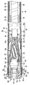
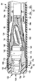
- FIG. 2A is a schematic longitudinal sectional view of an insertion portion of the endoscope of the endoscope system according to the first embodiment.
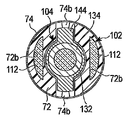
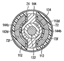
- 2B is a schematic cross-sectional view taken along line 2B-2B in FIG. 2A.
- 2C is a schematic cross-sectional view taken along line 2C-2C in FIG. 2A.
- 2D is an enlarged longitudinal sectional view of a portion indicated by reference numeral 2D in FIG. 2A.
- 2E is a schematic plan view showing a contact portion of the connecting pipe in the longitudinal sectional view shown in FIG. 2D.
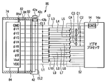
- FIG. 3A is a schematic diagram illustrating an electrical connection state between the solid-state imaging device and the video processor of the endoscope system according to the first embodiment.
- FIG. 3B is a schematic plan view showing the configuration of the electrical connector according to the first embodiment.
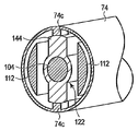
- FIG. 4 is a schematic perspective view of a state in which the main body of the distal end hard portion is removed from the distal end of the insertion portion of the endoscope of the endoscope system according to the second embodiment.
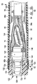
- FIG. 5 is a schematic longitudinal sectional view of an insertion portion of the endoscope of the endoscope system according to the third embodiment.
- FIG. 6 is a schematic longitudinal sectional view of an insertion portion of the endoscope of the endoscope system according to the fourth embodiment.
- FIG. 4 is a schematic perspective view of a state in which the main body of the distal end hard portion is removed from the distal end of the insertion portion of the endoscope of the endoscope system according to the second embodiment.
- FIG. 5 is a schematic
- FIG. 7A is a schematic perspective view showing a light guide used in the endoscope of the endoscope system according to the first to fourth embodiments.
- FIG. 7B is a schematic perspective view showing a light guide used in the endoscope of the endoscope system according to the first to fourth embodiments.
- FIG. 8 is a schematic cross-sectional view of the bending portion of the insertion portion of the endoscope of the endoscope system according to the first to fourth embodiments.
- FIG. 9A is a schematic diagram showing a ride guide used in an endoscope of the endoscope system according to the first to fourth embodiments.
- FIG. 9B is a schematic cross-sectional view showing a state in which the observation optical system and the light guide are arranged side by side along the line 9B-9B in FIG.
- FIG. 10A is a schematic cross-sectional view showing a state in which an observation optical system and a light guide are arranged in parallel inside a connecting pipe.
- FIG. 10B is a schematic cross-sectional view showing a state in which an observation optical system and a light guide are arranged in parallel inside the connecting pipe.
- FIG. 11 is a schematic perspective view showing a state in which a light guide is covered with a covering tube having a slit.
- FIG. 12 is a schematic longitudinal sectional view of an insertion portion of an endoscope having a shape different from those of the first to fourth embodiments.
- FIG. 13 is a schematic longitudinal sectional view of an insertion portion of an endoscope according to a reference embodiment.
- FIG. 14A is a schematic cross-sectional view of the endoscope according to the reference embodiment taken along line 14A-14A in FIG. 14B is a schematic cross-sectional view of the endoscope according to the reference embodiment taken along line 14B-14B in FIG.
- FIG. 15A is a schematic cross-sectional view of the endoscope according to the reference embodiment taken along line 15A-15A in FIG.
- FIG. 15B is a schematic cross-sectional view of the endoscope according to the reference embodiment taken along line 15B-15B in FIG.
- FIG. 15C is a schematic enlarged view of a position indicated by 15C in FIG. 13 of the endoscope according to the reference embodiment.
- FIG. 16A is a schematic cross-sectional view of the endoscope according to the reference embodiment taken along line 16A-16A in FIG.
- FIG. 16B is a schematic cross-sectional view of the endoscope according to the reference embodiment taken along line 16B-16B in FIG.
- an endoscope system 10 includes an electronic endoscope 12, a video processor 14 that can be attached to and detached from the electronic endoscope 12, and a light source device 16.
- the video processor 14 and the light source device 16 are external devices.
- a monitor 20 is connected to the video processor 14.
- the electronic endoscope 12 includes, for example, an elongated insertion portion 32 for insertion into a narrow space such as in a tube hole, and an operation portion 34 provided at the proximal end portion of the insertion portion 32 for operating the insertion portion 32. Have.
- the operation unit 34 includes an operation unit main body 42 having a bending operation knob (bending operation unit) 42 a, a universal cord 44, a light guide connector 46, a video cable 48, and an electrical connector (connector connection unit) 50.
- the inside of the operation section main body 42 accommodates various structures extending from the inside of the insertion section 32, and also serves as a housing section that houses a rotating section 42b such as a pulley or a sprocket for bending the bending section 64 described later.
- the outside of the operation unit main body 42 functions as a gripping unit that is gripped by the user.
- the bending operation knob 42a is interlocked with the rotation portion 42b inside the operation portion main body 42 and the shaft portion 42c.
- the bending tube 82 that is, the bending portion 64 can be bent by operating the wire 84 described later via the rotating portion 42b.
- the rotation part 42b is formed with the metal material, and has electroconductivity.
- the operation portion main body 42 and the bending operation knob 42a are at least covered with an insulating resin material or the like.
- a universal cord 44 extends from the operation unit main body 42.
- the universal cord 44 is covered with an insulating resin material such as polyurethane.
- a light guide connector 46 having a light guide end 46 a connected to the recess 16 a of the light source device 16 is disposed at the distal end of the universal cord 44 with respect to the operation unit main body 42.
- a video cable 48 extends from the side of the light guide connector 46, and an electrical connector 50 connected to the video processor 14 is disposed at the distal end of the video cable 48 with respect to the light guide connector 46.
- the insertion part 32 shown in FIG.1 and FIG.2A has the front-end
- the distal end hard portion 62 includes a main body 72 formed of a transparent resin material, and a connecting pipe 74 disposed at the base end of the main body.
- the main body 72 and the connecting pipe 74 of the distal end hard portion 62 are each formed in a substantially cylindrical shape, for example.
- a concave portion 72 a in which the distal end of the connecting pipe 74 is disposed is formed on the outer peripheral surface of the distal end rigid portion 62 on the proximal end side of the main body 72.
- the disposition of the main body 72 and the connection pipe 74 can be positioned by disposing the front end of the connection pipe 74 in the recess 72 a on the proximal end side of the main body 72 of the distal end hard part 62.
- the main body 72 of the distal end hard portion 62 is non-conductive (insulating).
- the connecting pipe 74 is preferably formed of a metal material such as stainless steel, and has conductivity.
- the bending portion 64 has a bending tube 82 in which a plurality of bending pieces (node rings) 82a, 82b, 82c,.
- the distal end of a plurality of wires 84 for bending the bending tube 82 is fixed to the wire fixing portion 84a at the most distal bending piece 82a.
- the wire fixing portion 84a is formed, for example, by pressing the most distal bending piece 82a.
- the wire 84 extends from the wire fixing portion 84 a to the operation portion main body 42 of the operation portion 34 shown in FIG. 1, and the proximal end of the wire 84 is connected to the rotation portion 42 b inside the operation portion main body 42.
- the wire 84 is covered with the coil tube 86 inside the tubular portion 66. Therefore, when the bending operation knob 42a is operated, the bending tube 82 can be freely bent by moving the wire 84 in the axial direction via the rotating portion 42b.
- the wire 84 is formed with the strand made from a metal material, and has electroconductivity.
- the outer peripheral surface of the bending piece 82a at the extreme end of the bending tube 82 is fixed to the inner peripheral surface of the connection tube 74.
- the bending tube 82 having the bending pieces 82a, 82b, 82c,... is preferably made of a metal material such as stainless steel and has conductivity.
- the connecting pipe 74 and the bending pipe 82 are fixed by a connecting portion 90 such as a conductive adhesive or a screw.
- FIG. 2A is an example in which both are connected using a conductive adhesive described later.
- the connecting portion 90 is an adhesive, it is fixed between the connecting tube 74 and the bending tube 82 with an adhesive applied circumferentially. That is, the connecting pipe 74 is electrically connected and electrically connected to the curved pipe 82.
- Member) 42b is electrically connected and has conductivity.
- the connecting tube (ground metal member) 74 of the distal end hard portion 62, the bent tube (ground metal member) 82 and the wire (ground metal member) 84 of the bending portion 64 form the structure of the insertion portion 32. For this reason, these grounding metal members do not require a separate conductor or the like for conducting the grounding metal member, and can prevent the insertion portion 32 from increasing in diameter.
- the rotating portion 42b is electrically connected to an electric wire L2 that is a GND signal line, which will be described later, inside the operation portion 34, for example, inside the operation portion main body 42, by a conductive wire EL1. It is preferable that the rotating portion 42b and the electric wire L2 are electrically connected to each other inside the operation portion main body 42 of the operation portion 34, but the inside of the universal cord 44, the inside of the light guide connector 46, the video cable 48, and the like. Either the inside or the inside of the electrical connector 50 may be used.
- the outer peripheral surface of the connecting tube 74 of the distal end hard portion 62 and the outer peripheral surface of the bending tube 82 of the bending portion 64 are covered with a common skin 80. Since the outer skin 80 has an insulating property, electricity is prevented from flowing from the radially outer side of the insertion portion 32 to the connecting pipe 74 and the bending pipe 82. Further, as shown in FIGS. 2A and 2D, a thread 80a is wound around the outer peripheral surface of the main body 72 of the distal end hard portion 62 and the outer peripheral surface of the outer skin 80, and an adhesive 80b is applied from the outer side of the thread 80a. Yes.
- the tubular portion 66 has a spiral tube 92, a blade 94, and a skin 96.
- the spiral tube 92 is preferably made of a metal material such as stainless steel, and has conductivity.
- the bending tube 82 and the spiral tube 92 are fixed with conductive adhesive, screws, or the like. That is, the bending tube 82 has electrical conductivity and is electrically connected to the spiral tube 92.
- the curved tube 82 and the spiral tube 92 may be connected using a conductive connection tube (not shown) different from the connection tube 74 described above.
- the spiral tube 92 is electrically connected to an electric wire L2 that is a GND signal line, which will be described later, inside the operation unit 34, for example, inside the operation unit main body 42, by a conductive wire EL2. . It is preferable that the spiral tube 92 and the electric wire L2 are electrically connected to each other inside the operation unit main body 42 of the operation unit 34, but inside the universal cord 44, the light guide connector 46, and the video cable 48. Any of the electrical connectors 50 may be used.
- the connecting pipe (grounding metal member) 74 of the distal end hard part 62, the bending pipe (grounding metal member) 82 and the spiral pipe (grounding metal member) 92 of the bending part 64 form a structure of the insertion part 32. For this reason, these ground metal members do not require a separate conducting wire or the like for conducting the ground metal member, and can prevent the insertion portion 32 from increasing in diameter.
- the illumination optical system 102 includes a light guide 112 having one end (distal end) disposed on the distal end hard portion 62 of the insertion portion 32 and the other end (proximal end) disposed on the light guide connector 46 of the operation portion 34. Yes. As shown in FIG. 2B, one end of the light guide 112 according to this embodiment is disposed in a hole 72 b formed in the main body 72 of the distal end hard portion 62.
- One end of the light guide 112 is abutted and fixed to an R-shaped portion (not shown) formed at the bottom of the hole 72b.
- the light guide end 46 a of this embodiment can be connected to the recess 16 a of the light source device 16. Therefore, the illumination light from the light source device 16 is transmitted through the light guide end 46a from the recess 16a through the light guide 112, and the illumination light is emitted from the illumination optical system 102 in the distal end hard portion 62. At this time, the illumination light is widened by the R-shaped portion, and it is possible to irradiate the illumination light over a wide range from the main body 72 of the distal end hard portion 62 formed of a transparent resin. Accordingly, the subject is illuminated.
- the tip of the light guide 112 is abutted against the main body 72 without the metal member being interposed between the main body 72 formed of a resin material, so that the thickness of the metal member is not necessary, and the tip of the insertion portion 32 is not required.
- the diameter can be reduced.
- the observation optical system 104 includes an objective lens unit 122, a solid-state imaging device unit 124, and an imaging cable 126.
- the objective lens unit 122 and the solid-state image sensor unit 124 are disposed on the distal end hard portion 62 of the insertion portion 32.
- the objective lens unit 122 is disposed at the most distal end of the observation optical system 104, and the solid-state image sensor unit 124 is disposed at the base end of the objective lens unit 122.
- One end of the imaging cable 126 is disposed at the base end of the solid-state imaging device unit 124, and the other end is connected to the electrical connector 50. By connecting this electrical connector 50 to the video processor 14, the electrical signal output from the image sensor 148 inside the hard end 62 of the insertion portion 32 can be displayed as an image on the monitor 20.
- the objective lens unit 122 includes a first lens group (optical element) 132 and a first holding frame (frame member) 134 that holds the first lens group 132.
- the first holding frame 134 is inserted into and fixed to the through hole 72c of the main body 72 of the distal end hard portion 62, and at least a part of the first holding frame 134 is exposed at the distal end surface of the main body 72 of the distal end hard portion 62.
- the 1st holding frame 134 is formed, for example with metal materials, such as stainless steel material, and has electroconductivity.
- the solid-state image sensor unit 124 includes a second lens group (optical element) 142, a first holding frame 134, a second holding frame (frame member) 144 that holds the second lens group 142, and a second holding frame.
- a reinforcing frame (frame member) 146 disposed on the outer peripheral portion of the base end of 144; an imaging element (optical element) 148 housed in the reinforcing frame 146 and connected to the second lens group 142; 150.
- the 2nd holding frame 144 is formed, for example with metal materials, such as stainless steel material, and has electroconductivity.
- the reinforcing frame 146 is preferably formed of a metal material such as a stainless steel material and has conductivity.
- An adhesive is filled between the second holding frame 144 and the image sensor 148 and between the reinforcing frame 146 and the image sensor 148. Further, the reinforcing frame 146 and the second holding frame 144 usually do not have a structure for positively conducting with the image sensor 148. However, the adhesive is not completely insulated due to the presence of air layers.
- the electronic endoscope 12 includes a connecting tube (ground metal member) 74 of the distal end hard portion 62, a conductive member (for example, the first holding frame 134) of the objective lens unit 122 of the observation optical system 104, and a solid-state image sensor unit 124. At least one of the conductive members (the second holding frame 144 or the reinforcing frame 146) is electrically connected.
- a substantially U-shaped or substantially crescent shaped slit 74a is formed in the connecting pipe 74 of the distal end hard portion 62 by, for example, press working, and the tongue formed by the slit 74a.
- the contact portion (claw portion) 74b is folded inward and brought into contact with the second holding frame 144 as shown in FIGS. 2C and 2D.
- the contact part 74b is folded in advance in the radial direction of the connection pipe 74 in advance, and the connection pipe 74 is assembled to the main body 72 of the distal end hard part 62 in this state.
- the contact part 74b and the 2nd holding frame 144 contact, and the connection pipe 74 and the 2nd holding frame 144 conduct
- the contact part 74b functions as a conductive connection part.
- the contact part 74b is formed by being folded inside the connecting pipe 74 made of, for example, metal, the contact part 74b is elastically deformable and has a spring property (biasing force), and is always brought into contact with the second holding frame 144. The state can be maintained.
- the outer shape of the second holding frame 144 of the solid-state image sensor unit 124 of the observation optical system 104 is arbitrary, but a structure that ensures conduction between the second holding frame 144 and the connection pipe 74 of the distal end hard portion 62. It is preferable that the second holding frame 144 and the connecting pipe 74 are disposed as close as possible. The structure in which the second holding frame 144 is brought closer to the contact portion 74b is easier to maintain the strength than the contact portion 74b formed in the connection pipe 74. For this reason, the second holding frame 144 has an outer shape such as a chicken crown having a thickness in the vertical direction in FIG. 2C, and the second holding frame 144 is connected to the connecting pipe 74, that is, the ground metal member. It is approaching. It is preferable for the second holding frame 144 to extend symmetrically in opposite directions with the observation optical system 104 as the central axis because it is easy to manufacture the second holding frame 144.
- the imaging cable 126 is connected to a terminal disposed on the electrical connector 50 of the operation unit 34 through the insertion unit 32.
- the electrical connector 50 is electrically connected to the video processor 14.
- the imaging cable 126 includes vertical drive system signals ( ⁇ V1 to ⁇ V4), horizontal drive system signals ( ⁇ H1, ⁇ H2, and ⁇ R), video output signals (Vout), power supply (VDD), ground ( GND) is a composite cable composed of 10 signal lines.
- the VDD and GND signal lines use electric wires L1 and L2, respectively, and the other eight signal lines use coaxial lines L3,.
- the vertical drive system signals ⁇ V1 and ⁇ V3 are ternary pulse (High, Middle, Low) signals including a negative voltage (Low).
- the vertical drive system signals ⁇ V2 and ⁇ V4 are binary pulse (Middle, Low) signals including a negative voltage (Low).
- the horizontal drive system signals ( ⁇ H1, ⁇ H2, ⁇ R) are binary pulse (High, Middle) signals that do not include a negative voltage.
- the VDD and GND terminals of the solid-state image sensor unit 124 are connected to the VDD and GND terminals of the video processor 14 via electric wires L1 and L2, respectively.
- the terminals for the vertical drive system signals ( ⁇ V1 to ⁇ V4), horizontal drive system signals ( ⁇ H1, ⁇ H2, ⁇ R), and video output signal (Vout) of the solid-state imaging device unit 124 are respectively connected to the core wires of the coaxial lines L3,.
- the outer conductors (shield wires) of all the coaxial lines L3,..., L10 are collectively connected to the GND wire L2.
- the inner conductors (core wires) of the coaxial lines L3,..., L6 of the vertical drive system signals ( ⁇ V1 to ⁇ V4) and the shield wires are connected via capacitors C1,.
- the shield lines of the coaxial lines L3,..., L6 for the vertical drive system signal are collectively connected to the GND wire L2.
- a board 162 shown in FIG. 3B is provided inside the connector case 52 in FIG. 1 of the electrical connector 50.
- the substrate 162 is provided with contact portions P1,..., P10 and coaxial contacts D1,.
- the contact portions P1,..., P10 are used for the core wires and shield wires of VDD, GND, vertical drive system signals. That is, the contact portions P1, P2 are respectively connected to the electric wires L1, L2, the contact portions P3,..., P6 are respectively connected to the core wires of the coaxial lines L3,. Connected to the shield lines of the coaxial lines L3,..., L6.
- the internal contacts of the coaxial contacts D1,..., D4 are connected to the core wires of the coaxial lines L7,..., L10, and the external contacts of the coaxial contacts D1,. Are connected to the shielded lines of the coaxial lines L7,..., L10.
- the contact portions P7,..., P10 of the shield line of the vertical drive system signal and the GND contact portion P2 are provided at the same potential at the GND portion 164 on the substrate 162.
- the GND portion 164 is desirably as large as possible.
- the contact points P3,..., P6 of the core line of the vertical drive system signal and the GND part 164 are connected via capacitors C1,. Thereby, the connection of the electrical connector 50 shown in FIG. 3A is realized.
- the electronic endoscope 12 has a plurality of signal lines (electric wires L1, L2, coaxial lines L3,%) Electrically connected to the solid-state imaging device unit 124 inside the distal end portion of the insertion portion 32. , L10) is connected to the external contact portion by the electric connector 50 of the operation portion.
- the electronic endoscope 12 uses capacitors C1,..., C4 as signal lines (core lines of L3,..., L6) for transmitting an imaging element drive pulse including a negative voltage among a plurality of signal lines of the imaging cable 126.
- the wire 84 and the rotating portion 42b are each formed of a conductive metal member (hereinafter referred to as a ground metal member), and these ground metal members are connected and electrically connected to each other. Further, when the electric connector 50 is connected to the video processor 14 in a state where the electric wire EL1 is connected to the electric wire L2, these ground metal members are electrically connected to the ground portion (GND) 14a of the video processor 14.
- GND ground portion
- the second holding frame 144 of the observation optical system 104, the connecting tube 74 of the distal end hard portion 62 of the insertion portion 32, and the bending tube 82 of the bending portion 64 are each made of a conductive metal member (hereinafter referred to as a ground metal member).
- the ground metal members are connected to each other and electrically connected. Further, when the electric connector 50 is connected to the video processor 14 in a state where the electric wire EL2 is connected to the electric wire L2, these ground metal members are conducted to the ground portion (GND) 14a of the video processor 14.
- the second holding frame 144 of the observation optical system 104, the connecting tube 74 of the distal end hard portion 62 of the insertion portion 32, the bending tube 82 of the bending portion 64, the wire 84, the rotating portion 42b, the electric wire EL1, and the electric wire L2 are electrically connected.
- these members are at the same potential as the ground portion 14a of the video processor 14 at all portions from the distal end of the insertion portion 32 to the electrical connector 50.
- the second holding frame 144 of the observation optical system 104, the connecting tube 74 of the distal end hard portion 62 of the insertion portion 32, the bending tube 82 of the bending portion 64, the electric wire EL2, and the electric wire L2 are electrically connected.
- the first holding frame 134 and the reinforcing frame 146 that are electrically connected to the second holding frame 144 also have the same potential as the ground portion 14 a of the video processor 14.
- connection tube 74 and the metal member of the solid-state imaging device unit 124 are not electrically connected, when a high-frequency treatment instrument is used together with the endoscope, for example, at the distal end of the insertion portion of the endoscope.
- the applied leakage current and static electricity flow to the first holding frame 134 and to the second holding frame 144 and the reinforcing frame 146. Thereafter, there is a risk that the electric charge that has gone out of place will fly to the solid-state imaging device 148. As a result, there is a possibility that problems such as noise appear on the image obtained by the endoscope.
- the second holding frame 144 holds the first holding current in the tip of the insertion portion 32. Since it is electrically connected to the frame 134, it flows to the ground part 14 a of the video processor 14. Thereby, it is possible to prevent an unintended current from flowing through the solid-state imaging device 148, and it is possible to prevent electrical influences such as noise on the image obtained by the electronic endoscope 12. Therefore, when the electronic endoscope 12 and the high-frequency treatment tool (not shown) are used together, or when static electricity (charge) is applied to the tip carelessly, current does not flow into the image sensor 148. By flowing through the ground metal (GND), it is possible to prevent an electrical influence on an image obtained by the electronic endoscope 12.
- GND ground metal
- the conducting wire for the imaging cable is attached to the CCD holding frame. That is, it is necessary to increase the outer diameter of the insertion portion by the amount of the conductive wire.
- the rotating portion 42b and the electric wire EL1 are described as being electrically connected.
- the shaft portion 42c and the electric wire EL1 are electrically connected. It may be a structure connected to.
- the spiral tube 92 is also electrically connected to the connection tube 74 and the bending tube 82 and is electrically connected to the electric wire L2 via the electric wire EL2.
- the helical tube 92 is insulated. You may form with the material which has property. In this case, since the wire 84 has conductivity, it is possible to prevent a current that affects the solid-state image sensor unit 124 from flowing.
- two contact points 74b are formed so as to face each other.
- the number of contact points 74b is not limited to two, and may be one or plural (for example, three or more). good.
- the electric wires EL1 and EL2 are connected to the electric wire L2 of the imaging cable 126 and the ground portion 14a of the video processor 14 is connected inside the operation unit 34 has been described.
- the electric wires EL1 and EL2 are imaged. You may connect directly to the ground part 14a of the video processor 14 without going through the electric wire L2 of the cable 126.
- a structure in which an electric wire that can be directly connected to the ground portion 14a is connected to the wire 84 may be used.
- FIG. 1 This embodiment is a modification of the first embodiment.
- the same members as those described in the first embodiment are denoted by the same reference numerals, and detailed description thereof is omitted.
- the protrusion (contact part) 74c is formed so as to protrude toward the inside in the radial direction of the connection pipe 74.
- the protrusion 74 c is formed so as to sandwich the second holding frame 144 of the solid-state image sensor unit 124 of the observation optical system 104.
- the outer skin 80 (refer FIG. 2A) which is not shown in figure is actually arrange
- a conductive adhesive 172 is applied between the connecting tube 74 and the second holding frame 144 of the solid-state image sensor unit 124 of the observation optical system 104, and the second holding frame 144 and the objective lens are applied.
- a conductive adhesive 174 is applied between the first holding frame 134 of the unit 122.
- a conductive adhesive 176 is applied between the second holding frame 144 and the reinforcing frame 146.
- These adhesives 172, 174, and 176 are preferably the same. For this reason, the connecting pipe 74, the first holding frame 134, the second holding frame 144, and the reinforcing frame 146 are electrically connected, and conduction between them is ensured.
- Examples of the conductive adhesives (conductive connection portions) 172, 174, and 176 include an epoxy adhesive mixed with silver.
- the first embodiment and the first embodiment As in the second embodiment, the stress applied to the second holding frame 144 of the solid-state image sensor unit 124 applied by applying the contact portion 74b and the protrusion 74c of the connecting pipe 74 can be reduced. Accordingly, it is possible to reduce a constant load due to an external force applied to the solid-state image sensor unit 124.
- the adhesives 172, 174, and 176 are also preferable to use together with the contact portion 74b of the connection pipe 74 described in the first embodiment and the protrusion 74c of the connection pipe 74 described in the second embodiment. It is. Similarly, conductive adhesive is provided between at least one of the pin member 182 and the first holding frame 134 and between the pin member 182 and the second holding frame 144 which are conductive members described in the fourth embodiment described later. It is also preferable that the agent 174 is applied.
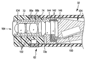
- a through hole 72 d is formed in the main body 72 of the distal end hard portion 62 from the radially outer side.
- a pin member (conductive connecting portion) 182 made of a metal material and having conductivity is inserted into the through hole 72d.
- the radially inner end is abutted against at least one of the first holding frame 134 and the second holding frame 144 of the solid-state image sensor unit 124.
- the first and second holding frames 134, 144 of the solid-state image sensor unit 124 are connected to the connection tube 74.
- the pin member 182 is formed so as to protrude slightly outward in the radial direction from the connection pipe 74, and the pin member 182 is filed together with the outer peripheral surface of the connection pipe 74, for example. It is preferable to ensure conductivity.
- the outer shape of the second holding frame 144 of the solid-state image sensor unit 124 of the observation optical system 104 according to this embodiment is formed in a cylindrical shape. That is, the shape of the second holding frame 144 according to this embodiment is different from that of the second holding frame 144 described in the first to third embodiments.
- the present embodiment unlike the contact portions 74b, protrusions 74c, and adhesive 172 described in the first to third embodiments, there is no need to bring the second holding frame 144 close to the connecting pipe 74. For this reason, the part provided with the upper and lower wall thickness used in the second holding frame 144 of the first to third embodiments can be excluded, and the pin member 182 bears the part provided with the upper and lower wall thickness.
- the second holding frame 144 according to the present embodiment is easier to process than the first to third embodiments. Therefore, the molding of the first holding frame 134 fitted to the second holding frame 144 and the main body 72 of the distal end hard portion 62 can be simplified as compared with the case described in the first to third embodiments.
- the light guide 112 is formed in a state where the vicinity of the distal end portion has a substantially semicircular cross section from the distal end toward the proximal end side. That is, as shown in FIG. 2B, the vertical direction of the light guide 112 is formed longer than the horizontal direction. For this reason, the outer diameter of the main body 72 of the distal end hard portion 62 of the insertion portion 32 is made smaller than that in the case where a light guide having the same cross-sectional area and a circular cross section is disposed in the main body 72 of the distal end hard portion 62 be able to.
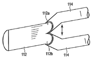
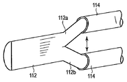
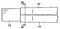
- the light guide 112 is preferably divided into two parts (two hands) indicated by reference numerals 112 a and 112 b in FIGS. 7A and 7B from the vicinity of the curved portion 64.
- the cross section of the bifurcated portion indicated by reference numerals 112a and 112b is preferably formed in a circular shape, and the outer peripheral surfaces of these light guides 112a and 112b are covered with a protective tube 114, respectively.
- the protective tube 114 is preferably made of, for example, nylon or silicon resin.
- the protective tube 114 is preferably a light-colored light colored tube. Then, when the light guide 112 is guided and there is a portion where the light guide is broken in the protective tube, light leaks from the side surface, and the folding positions of the light guides 112a and 112b can be identified.
- FIG. 7A shows a state in which the vicinity of the bifurcated base is covered with the protective tube 114
- FIG. 7B shows a state in which the rear end side is covered with the protective tube 114 from the vicinity of the base.
- the light guide 112 is shape
- the light guide is not molded so as to separate the portions indicated by reference numerals 112a and 112b (when bundles divided into two hands are arranged in a straight line)
- the light guide is interposed between the rivet 83a of the bending tube 82 and the imaging cable 126. Are easy to be placed and easily pinched. For this reason, it is difficult to avoid applying a large force to the light guide.
- the light guides 112a and 112b are bent and separated from each other by molding the pair of light guides 112 separately into two parts denoted by reference numerals 112a and 112b, respectively.
- the light guide 112 is indicated by reference numerals 112a and 112b so as to release the force applied to the light guide 112.
- the part can be moved. For this reason, it is possible to prevent the fiber constituting the light guide 112 from being bent by applying a large force to the light guide 112.
- the position of the string guide 84b of the bending tube 82 through which the wire 84 is passed is in the middle of the upper and lower sides.
- the light guides 112a and 112b can be arranged symmetrically with the imaging cable 126 at the center position. That is, by forming the light guides 112a and 112b in the shape described above, the bent tube 82 can arrange the built-in objects symmetrically. For this reason, the internal space of the insertion part 32 can be used uniformly, and interference of a built-in thing can be reduced.
- the outer periphery of the divided light guides 112a and 112b is covered with a covering tube 114.
- the surface on the side close to the connecting pipe 74 is arcuate and the two light guides 112a and 112b are combined.
- the surface on the side separated from the tube 74 is formed along the outer shape of, for example, the first holding frame 134 of the observation optical system 104. For this reason, since the dead space can be reduced while maintaining the area of the light guides 112a and 112b, the outer diameter of the distal end hard portion 62 of the insertion portion 32 can be further reduced.
- FIGS. 10A and 10B show the distal end side of the insertion portion 32 with respect to the position shown in FIG. 9B. That is, the light guide 112 in FIGS. 10A and 10B corresponds to the position indicated by reference numeral 112 in FIG. 9A.
- the surface of the light guide 112 that is close to the connection tube 74 has an arc shape, and the surface that is separated from the connection tube 74 is, for example, the second holding of the observation optical system 104. It is formed along the outer shape of the frame 144. In this case, since the second holding frame 144 has a substantially L-shaped portion 144a, the light guide 112 also has a substantially L-shaped portion 112c. As shown in FIG.
- the surface of the light guide 112 that is close to the connecting tube 74 is arcuate, and the surface that is separated from the connecting tube 74 is also the second holding frame of the observation optical system 104, for example. It is arcuate along the outer shape of 144.
- the second holding frame 144 has the arc-shaped portion 144b
- the light guide 112 also has the arc-shaped portion 112d. Therefore, since the dead space can be reduced while maintaining the area of the light guide 112, the outer diameter of the distal end hard portion 62 of the insertion portion 32 can be further reduced.
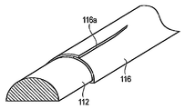
- the light guide 112 is covered with a protective tube 116.
- the covering tube 116 is molded in a state in which a cutting edge 116a is placed on the tip side. For this reason, the peripheral length of the front end side of the protective tube 116 can be made variable. Therefore, the protective tube 116 can be covered with a shape in which the light guide 112 is molded so as to be covered. That is, it is possible to increase adhesion when the protective tube 116 is brought into close contact with the outer peripheral surface of the light guide 112. Therefore, the protective tube 116 can be prevented from shifting to the rear end side of the light guide 112. In addition, the diameter of the protective tube 116 can be reduced, and the distal end of the insertion portion 32 of the electronic endoscope 12 can be reduced accordingly.
- the main body 72 of the distal end hard portion 62 and the first holding frame 134 of the solid-state image sensor unit 124 are in contact with each other and are fitted together.
- the main body 72 of the distal end hard portion 62 and the second holding frame 144 of the solid-state image sensor unit 124 are in contact with each other and fitted.
- the second holding frame 144 of the observation optical system 104 is fitted in the hole 72 e of the main body 72 of the distal end hard portion 62.
- the inclination of the first holding frame 134 and the second holding frame 144 when assembled is the main body 72 of the distal end hard portion 62. It is difficult to affect the inclination of the solid-state image sensor unit 124. Therefore, the inclination due to the assembly of the main body 72 and the solid-state image sensor unit 124 is reduced. Accordingly, as a result, the inclination between the light guide 112 assembled to the main body 72 and the solid-state image sensor unit 124 can be reduced.
- interference between the light guide 112 and the observation optical system 104 due to the inclination of the observation optical system 104 in the insertion portion 32 can be reduced, and for example, fiber breakage of the light guide 112 due to compression of the solid-state image sensor unit 124 is prevented. be able to.
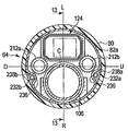
- an illumination optical system 102 As shown in FIGS. 13 to 16B, an illumination optical system 102, an observation optical system 104, and a channel tube 106 are disposed in the insertion portion 32 of the endoscope 12 according to this reference embodiment.
- the illumination optical system 102 has a pair of light guides 212a and 212b whose cross sections shown in FIGS. 14A and 14B are substantially circular.
- the observation optical system 104 includes an objective lens unit 122, a solid-state image sensor unit (imaging unit) 124 having a substantially rectangular cross section shown in FIG. 14A, and an imaging cable 126 having a substantially circular cross section shown in FIG. 15A. And have.
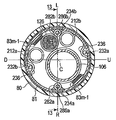
- the solid-state image sensor unit 124 is located between the light guide 212a between the U direction and the L direction, the light guide 212b between the D direction and the R direction, with respect to the central axis C of the bending portion 64.
- a channel tube 106 is disposed between the U direction and the R direction between the D direction and the L direction.
- 14A is larger than the area of the cross section of the imaging cable 126 shown in FIG. 15A. That is, the observation optical system 104 has an imaging cable 126 smaller than the solid-state imaging element unit 124.
- the bending portion 64 of the insertion portion 32 has an outer skin 80 and a bending tube 82.
- a blade (mesh tube) 81 is disposed between the outer skin 80 and the curved tube 82.
- Bending tube 82 has a plurality of bending pieces (joint rings) 82a, 82b, 82c, ... , 82 m-1, 82 m, 82 m + 1, ..., and 82 n-2, 82 n- 1, 82 n, adjacent , 83 m ⁇ 2 , 83 m ⁇ 1 , 83 m ,..., 83 n ⁇ 2 , 83 n ⁇ 1 , which rotatably couple the bending pieces with respect to each other.
- the most distal bending piece 82 a is fitted and fixed to the distal end hard portion 62.
- the most proximal bending piece 82 n is fitted and fixed to a connecting portion 222 between the tubular portion 66.
- the intermediate bending piece 82 m is defined between the bending pieces 82 n of the most proximal the bending piece 82a of the most distal end of the bendable tube 82 in this reference embodiment.
- the intermediate bending pieces 82 m among the bending tube 82 may be in the front end nearer the middle, may be the proximal end nearer the middle.
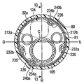
- angle wires 232a and 232b on the U-direction side and the D-direction side are respectively brazed and fixed to the inner peripheral surface of the most distal node ring 82a of the bending tube 82.
- the inside of the wire guide 236 is formed as brazed fixing portions 238a and 238b at the tips of the angle wires 232a and 232b, and the angle wires 232a and 232b are fixed.
- Angle wires 234a and 234b on the R direction side and the L direction side are fixed by brazing.
- the inside of the wire guide 236 is formed as brazing fixing portions 240a and 240b at the tips of the angle wires 234a and 234b, and the angle wires 234a and 234b are fixed.
- the angle wires 232a and 232b on the U direction side and the D direction side are fixed at positions substantially opposite to the central axis C, and the angle wires 234a and 234b on the R direction side and the L direction side are fixed on the central axis C.
- the angle wires 234a and 234b on the R direction side and the L direction side are fixed at the rear position along the central axis C with respect to the U direction side angle wire 232a, and fixed on the rear side position.
- the angle wires 234a and 234b on the R direction side and the L direction side with respect to the angle wire 232b are fixed at a rear position along the central axis C.
- the fixed positions of the angle wire 232a on the U direction side, the angle wire 232b on the D direction side, the angle wire 234a on the R direction side, and the angle wire 234b on the L direction side with respect to the node ring 82a are located away from each other. Therefore, heat can be prevented from being transmitted from the angle wire being brazed to the bending piece 82a to the angle wire fixed to the bending piece 82a. That is, it is possible to suppress the thermal influence on the angle wire fixed to the bending piece 82a.
- the observation optical system 104 occupies a smaller area in the cross section of the imaging cable 126 than in the cross section of the solid-state image sensor unit 124. For this reason, the position (brazing fixing part 238a, 238b) which braces the front-end
- the positions where the tips of the angle wires 234a, 234b on the R direction side and the L direction side are brazed are set to positions facing the imaging cable 126, and among the bending pieces 82a at the most distal end Since the position is shifted in the front-rear direction, it is easy to secure a space for brazing. Therefore, the distal ends of the plurality of angle wires 232a, 232b, 234a, 234b can be more easily fixed to the bending portion 64 having the bending piece 82a having a relatively small outer diameter and inner diameter.
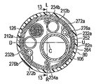
- the connecting portion 222 is disposed between the curved portion 64 and the tubular portion 66.
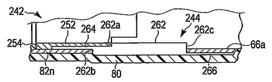
- the connection part 222 includes a first connection pipe 242 and a second connection pipe 244. Note that the first connecting pipe 242 and the second connecting pipe 244 are fixed with an adhesive, for example.
- the first connection pipe 242 includes a cylindrical portion 252 and an outward flange portion 254 provided at the tip of the cylindrical portion 252.
- the second connection pipe 244 includes a main body cylindrical portion 262, a cylindrical distal thin-walled cylindrical portion 264 provided at the distal end of the main body cylindrical portion 262, and a cylindrical base provided at the proximal end of the main body cylindrical portion 262. And an end-side thin cylindrical portion 266.
- An inner contact portion 262 a with which the proximal end of the cylindrical portion 252 of the first connection pipe 242 is contacted is formed on the inner peripheral side of the distal end side of the main body cylindrical portion 262.
- An outer abutting portion 262 b is formed on the outer peripheral side of the distal end side of the main body cylindrical portion 262, with which the proximal end of the most proximal node ring 82 n of the bending tube 82 of the bending portion 64 is in contact.
- the inner peripheral surface of the first connection pipe 242 and the second connecting pipe 244 is formed to be flush with or substantially flush with the inner peripheral surface.
- an inner contact portion 262c is formed on the inner peripheral side of the base end portion of the main body cylindrical portion 262 so that the distal end of the spiral tube 66a of the tubular portion 66 is contacted.
- the distal ends of the coil tubes 272a and 272b on the U direction side and the D direction side are preferably provided on the inner peripheral surface of the cylindrical portion 252 of the first connection pipe 242 from the distal end to the proximal end, respectively.
- it is fixed by brazing. That is, as shown in FIG. 15A, the inner side of the first connecting pipe 242 of the connecting portion 222 is formed as brazed fixing portions 276a and 276b at the tips of the coil tubes 272a and 272b on the U direction side and the D direction side, The tubes 272a and 272b are fixed.
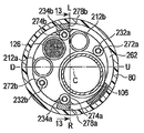
- the distal ends of the coil tubes 274a and 274b on the R direction side and the L direction side are preferably formed on the inner peripheral surface of the main body cylindrical portion 262 of the second connection pipe 244 from the distal end to the proximal end.
- Each is fixed by brazing, for example. That is, as shown in FIG. 15B, the inside of the second connection pipe 244 of the connection portion 222 is formed as brazed fixing portions 278a and 278b at the tips of the coil tubes 274a and 274b on the R direction side and the L direction side, The tubes 274a and 274b are fixed.
- the U-direction side coil tube 272a has a U-direction angle wire 232a
- the D-direction side coil tube 272b has a D-direction side angle wire 232b
- the R-direction side coil tube 274a has an R-direction side angle wire 234a
- the L direction side angle wire 234b is inserted in the L direction side coil tube 274b.
- the coil tubes 272a and 272b on the U direction side and the D direction side are fixed at positions facing the central axis C. For this reason, the position where the coil tubes 272a and 272b are attached is located far from the inner peripheral surface of the cylindrical portion 252 of the first connecting pipe 242, and is located on the inner peripheral surface of the cylindrical portion 252 of the first connecting pipe 242. It is possible to suppress heat from being transmitted from the coiled tube 272b being brazed to the coiled tube 272a that has been fixed to the inner peripheral surface of the cylindrical portion 252. Therefore, it is possible to suppress the thermal influence on the coil tube 272a fixed to the cylindrical portion 252 of the first connection pipe 242.
- the coil tubes 274a and 274b on the R direction side and the L direction side are fixed at positions substantially opposite to the central axis C.
- the position where the coil tubes 274a and 274b are attached is located far from the inner peripheral surface of the main body cylindrical portion 262 of the second connection pipe 244, and the inner periphery of the main body cylindrical portion 262 of the second connection pipe 244 Heat can be prevented from being transmitted from the coil tube 274b being brazed to the surface to the coil tube 274a already fixed to the inner peripheral surface of the main body cylindrical portion 262. Therefore, it is possible to suppress the occurrence of thermal influence on the coil tube 274a fixed to the main body cylindrical portion 262 of the second connection pipe 244.
- the coil tubes 272a and 272b are attached to the inner peripheral surface of the cylindrical portion 252 of the first connection pipe 242, and the coil tubes 274a and 274b are attached to the inner peripheral surface of the main body cylindrical portion 262 of the second connection pipe 244
- the first connecting pipe 242 and the second connecting pipe 244 are fixed.
- the first connection tube 242 is disposed on the side close to the distal end of the insertion portion 32
- the second connection tube 244 is disposed on the side close to the proximal end of the insertion portion 32
- the first connection tube 242 is disposed.
- the main body cylindrical portion 262 of the second connection pipe 244 is disposed outside the cylindrical portion 252.
- the outward flange portion 254 of the first connection tube 242 contacts the tip of the thin cylindrical portion 264 of the second connection tube 244.
- the proximal end of the cylindrical portion 252 of the first connection tube 242 contacts the inner contact portion 266 of the second connection tube 244.
- the outer peripheral surface of the first connecting pipe 242 and the inner peripheral surface of the second connecting pipe 244 are fitted and bonded together to fix them.
- the proximal end of the bending piece 82 n on the most proximal side is disposed on the outer periphery of the first connecting pipe 242 and the second connecting pipe 244.
- the connecting part 222 in which the first and second connecting pipes 242 and 244 are assembled can also be easily formed.
- the middle of the bending piece 82 m of the inner peripheral surface suitable coil pipe 282a that is closely wound in, the tip of 282b are fixed by bonding or brazing or the like. That is, as shown in FIG. 16A, to form an inner circumferential surface of the intermediate bending piece 82 m R direction side and the L-direction side of the coil pipe 282a, 282b of the distal end of the fixing portion 284a, as 284b, coil pipe 282a, 282b Is fixed.
- the most proximal end of the bending piece 82 n of the inner circumferential surface suitable coil pipe 282a that is closely wound in, the proximal end of 282b is fixed by bonding or brazing or the like Yes. That is, as shown in FIG. 16B, to form the most proximal the inner peripheral surface of the bending part 82 n in the R direction side and the L-direction side of the coil pipe 282a, the fixed part 286a of the proximal end of 282b, as 286b, a coil pipe 282a and 282b are fixed.
- An R-direction angle wire 234a is inserted through one coil pipe 282a, and an L-direction angle wire 234b is inserted through the other coil pipe 282b.
- coil pipe guides (not shown) are formed on the bending pieces 82 m + 1 ,..., 82 n ⁇ 1 between the intermediate bending piece 82 m and the most proximal bending piece 82 n, and the coil pipes 282a and 282b, Angle wires 234a and 234b are inserted through the coil pipes 282a and 282b, respectively.
- the bending pieces 82 m ,..., 82 n closer to the base end side than the intermediate bending piece 82 m are rotated relative to each other by the coil pipe 282 a. hard. Therefore, the most distal end bending piece 82b between the bending pieces 82a and bending piece 82 n of the most proximal end of, 82c, ..., 82 m- 1, 82 m, 82 m + 1, ..., 82 n-2, 82 n-
- the base end side can be made difficult to bend compared with the front end side. For this reason, it is possible to control the bending angle of the bending portion 64 so that the distal end side is larger than the proximal end side. The same control can be performed when the bending portion 64 is bent in the L direction (left direction).
- the coil pipes 282a and 282b which are preferably closely wound, are deformed when an external force is applied, unlike a hard pipe. For this reason, by using the coil pipes 282a and 282b, the coil pipes 282a and 282b are not formed as hard portions but function as a part of the bendable bending portion 64.
- the electronic endoscope has an insulating distal end hard portion body at the distal end, an insertion portion that is inserted into the hole, and a connector that is provided at the proximal end portion of the insertion portion and is electrically connected to the ground portion
- An operation part having a connection part, a ground metal member provided between the distal end hard part main body of the insertion part and the operation part, forming a structure of the insertion part, and being electrically connected to the ground part through the connector connection part
- An observation optical system that extends from the distal end of the insertion portion toward the operation portion, and a frame of the observation optical system. And a conductive connection for conducting the member to the ground metal member.
- the ground metal member is provided between the distal end hard portion main body of the insertion portion and the operation portion to form the structure of the insertion portion, it is difficult to affect the outer diameter of the insertion portion.
- the conductive connection portion is electrically connected to the ground portion and is conducted, and the conductive connection portion is conducted to the conductive frame member of the observation optical system, whereby the ground metal member and the frame member of the observation optical system are grounded.
- the same potential as the part it is possible to prevent high-frequency leakage current, static electricity, and the like from affecting optical elements such as an imaging element of the observation optical system. That is, this electronic endoscope can prevent the static electricity, high-frequency leakage current, and the like from affecting the observation optical system while reducing the outer diameter of the insertion portion as much as possible.
- the ground metal member has a cylindrical shape, the frame member is disposed inside the cylindrical ground metal member, and the conductive connection portion is formed on a part of the ground metal member and contacts the frame member. It is preferable to have a conductive contact portion projecting toward the frame member.
- the ground metal member as a structure is cylindrical, the frame member is disposed inside, and the conductive connection part is formed on a part of the ground metal member and the contact portion protruding toward the frame member is provided.
- the conductive connection portion is filled with a conductive adhesive between the ground metal member and the frame member. For this reason, the ground metal member and the frame member of the observation optical system can be set to the same potential as the ground portion with a simple structure of a conductive adhesive.
- the conductive connection portion conducts the ground metal member and the frame member through a conductive member.
- the ground metal member and the frame member of the observation optical system can be set to the same potential as the ground portion with a simple structure in which the conductive member is disposed between the conductive connection portion and the ground metal portion.
- spiral tube (ground metal member), 104 ... observation optical system, 122 ... Objective lens unit 124... Solid imaging element unit 126 126 Imaging cable 132.
- First lens group (optical element) 134.
- First holding frame (frame member) 142
- Second lens group (optical element) 144
- the second holding frame (frame member), 146 ... reinforcing frame (frame member), 148 ... solid-state imaging device (optical element).
Landscapes
- Health & Medical Sciences (AREA)
- Life Sciences & Earth Sciences (AREA)
- Surgery (AREA)
- Physics & Mathematics (AREA)
- Engineering & Computer Science (AREA)
- Optics & Photonics (AREA)
- Biomedical Technology (AREA)
- General Health & Medical Sciences (AREA)
- Pathology (AREA)
- Nuclear Medicine, Radiotherapy & Molecular Imaging (AREA)
- Biophysics (AREA)
- Heart & Thoracic Surgery (AREA)
- Medical Informatics (AREA)
- Molecular Biology (AREA)
- Animal Behavior & Ethology (AREA)
- Radiology & Medical Imaging (AREA)
- Public Health (AREA)
- Veterinary Medicine (AREA)
- Multimedia (AREA)
- Astronomy & Astrophysics (AREA)
- General Physics & Mathematics (AREA)
- Endoscopes (AREA)
- Instruments For Viewing The Inside Of Hollow Bodies (AREA)
Abstract
Description
第1実施形態について図1から図3Bを用いて説明する。
図1に示すように、本実施形態に係る内視鏡システム10は、電子内視鏡12と、この電子内視鏡12に着脱可能なビデオプロセッサ14及び光源装置16とを備えている。電子内視鏡12に対してビデオプロセッサ14及び光源装置16はそれぞれ外部デバイスである。ビデオプロセッサ14にはモニタ20が接続されている。
電子内視鏡12は、例えば管孔内等、狭い空間内に挿入するための細長い挿入部32と、挿入部32の基端部に設けられ挿入部32を操作するための操作部34とを有する。
操作部本体42の内部は挿入部32の内部から延出された各種構造体を収容するとともに、後述する湾曲部64を湾曲させるためのプーリやスプロケット等の回動部42bを収容する収容部として機能し、操作部本体42の外部は使用者に把持される把持部として機能する。湾曲操作ノブ42aは操作部本体42の内部の回動部42bと軸部42cを介して連動している。このため、湾曲操作ノブ42aを操作すると、回動部42bを介して後述するワイヤ84を動作させて湾曲管82、すなわち湾曲部64を湾曲させることができる。なお、回動部42bは金属材で形成されていることが好ましく、導電性を有する。一方、操作部本体42及び湾曲操作ノブ42aは絶縁性を有する樹脂材等で少なくとも外周が覆われている。
操作部本体42からはユニバーサルコード44が延出されている。ユニバーサルコード44は、例えばポリウレタン等の絶縁性の樹脂材で被覆されている。操作部本体42に対するユニバーサルコード44の遠位端部には光源装置16の凹部16aに接続されるライトガイド端部46aを有するライトガイドコネクタ46が配設されている。ライトガイドコネクタ46の側面からはビデオケーブル48が延出され、ライトガイドコネクタ46に対するビデオケーブル48の遠位端部にはビデオプロセッサ14に接続される電気コネクタ50が配設されている。
図2Aに示すように、先端硬質部62は透明な樹脂材で形成された本体72と、本体の基端に配設された接続管74とを有する。先端硬質部62の本体72及び接続管74はそれぞれ例えば略円筒状に形成されている。先端硬質部62の本体72の基端側の外周面には、接続管74の先端が配設される凹部72aが形成されている。このため、先端硬質部62の本体72の基端側の凹部72aに接続管74の先端を配置することにより、本体72と接続管74との配置を位置決めできる。なお、先端硬質部62の本体72は非導電性(絶縁性)である。一方、接続管74は例えばステンレス鋼材等の金属材で形成されていることが好ましく、導電性を有する。
なお、ワイヤ84は金属材製の素線で形成されていることが好ましく、導電性を有する。
照明光学系102は、一端(先端)が挿入部32の先端硬質部62に配設され、他端(基端)が操作部34のライトガイドコネクタ46に配設されたライトガイド112を備えている。図2Bに示すように、この実施形態に係るライトガイド112の一端は、先端硬質部62の本体72に形成された孔部72bに配設されている。そして、ライトガイド112の一端は、孔部72bの底部に形成された図示しないR形状部に突き当てられて固定されている。
本実施形態のライトガイド端部46aは、光源装置16の凹部16aに接続可能である。このため、光源装置16による照明光が凹部16aからライトガイド端部46aを通してライトガイド112内を伝送し、先端硬質部62内の照明光学系102から照明光が出射される。このとき、照明光はR形状部により広角化され、透明樹脂で形成された先端硬質部62の本体72から広い範囲に照明光を照射することが可能である。したがって、被写体が照明される。
このように、樹脂材で形成された本体72に金属部材を介することなく、ライトガイド112の先端を本体72に突き当てるので、金属部材の分の肉厚が不要であり、挿入部32の先端を細径化できる。
電気コネクタ50の図1中のコネクタケース52の内部には、図3Bに示す基板162が設けられている。基板162には、接点部P1,…,P10と、同軸接点D1,…,D4とが設けられている。
同軸接点D1,…,D4の内部接点は、同軸線L7,…,L10の各芯線に接続され、同軸接点D1,…,D4の外部接点は、内部接点の外周に絶縁された状態で設けられており、同軸線L7,…,L10の各シールド線に接続されている。
電子内視鏡12は、撮像ケーブル126の複数の信号線のうち、負電圧を含む撮像素子駆動パルスを伝送する信号線(同軸線L3,…,L6の芯線)をコンデンサC1,…,C4を介して撮像素子ユニット124の接地端子に接続している。
また、観察光学系104の第2保持枠144、挿入部32の先端硬質部62の接続管74、湾曲部64の湾曲管82はそれぞれ導電性を有する金属部材(以下、接地金属部材という)により形成され、これら接地金属部材同士が連結されて電気的に接続されている。さらに、電線EL2を電線L2に接続した状態で、電気コネクタ50がビデオプロセッサ14に接続されることで、これら接地金属部材がビデオプロセッサ14のグランド部(GND)14aに導通する。
このため、観察光学系104の第2保持枠144、挿入部32の先端硬質部62の接続管74、湾曲部64の湾曲管82、ワイヤ84、回動部42b、電線EL1、電線L2が電気的に接続されていることにより、これら部材は挿入部32の先端から電気コネクタ50までの全ての部位において、ビデオプロセッサ14のグランド部14aと同電位となる。同様に、観察光学系104の第2保持枠144、挿入部32の先端硬質部62の接続管74、湾曲部64の湾曲管82、電線EL2、電線L2が電気的に接続されていることにより、これら部材は挿入部32の先端から電気コネクタ50までの全ての部位において、ビデオプロセッサ14のグランド部14aと同電位となる。そして、第2保持枠144に電気的に接続された第1保持枠134及び補強枠146もビデオプロセッサ14のグランド部14aと同電位となる。
一方、上述したように、第2保持枠144をビデオプロセッサ14のグランド部14aと同電位とすることで、例えば挿入部32の先端に流された電流は、第2保持枠144が第1保持枠134に電気的に接続されているので、ビデオプロセッサ14のグランド部14aに流される。それにより、固体撮像素子148に意図しない電流を流すのを防止でき、電子内視鏡12により得られる画像にノイズが載る等、電気的な影響を防ぐことができる。
したがって、電子内視鏡12と高周波処置具(図示せず)とを併用するときや、不用意に静電気(電荷)が先端に印加されたときに、撮像素子148に電流を流れ込ませずに、接地金属(GND)に流すことで、電子内視鏡12により得られる画像に電気的な影響を与えるのを防ぐことができる。
また、この実施形態では螺旋管92も接続管74、湾曲管82と電気的に接続され、電線EL2を介して電線L2に電気的に接続されているものとして説明したが、螺旋管92を絶縁性を有する材料で形成しても良い。この場合、ワイヤ84が導電性を有するので、固体撮像素子ユニット124に影響を及ぼす電流が流れるのを防止できる。
また、この実施形態では、操作部34の内部で電線EL1,EL2を撮像ケーブル126の電線L2に接続し、ビデオプロセッサ14のグランド部14aに接続する場合について説明したが、電線EL1,EL2を撮像ケーブル126の電線L2を介することなく、直接ビデオプロセッサ14のグランド部14aに接続しても良い。例えば、ワイヤ84に直接グランド部14aに接続可能な電線が接続された構造であっても良い。
このように、導電接続部としての機能を有する突起74cを第2保持枠144に当てつける構造は、第1実施形態で説明したベロ状の接点部74bよりも、接点部74bを折り込む手間が省け、組み立てのリードタイムが削減できるため作業効率が上がる。
図5に示すように、接続管74と観察光学系104の固体撮像素子ユニット124の第2保持枠144との間には導電性の接着剤172が塗布され、第2保持枠144と対物レンズユニット122の第1保持枠134との間には、導電性の接着剤174が塗布されている。さらに、第2保持枠144と補強枠146との間に導電性の接着剤176が塗布されている。これら接着剤172,174,176は同一のものが用いられることが好ましい。このため、接続管74、第1保持枠134、第2保持枠144及び補強枠146は電気的に接続され、これらの間の導通が確保される。
なお、導電性の接着剤(導電接続部)172,174,176としては、エポキシ系の接着剤に、銀を混ぜ合わせたものが一例として挙げられる。
図6に示すように、先端硬質部62の本体72には、径方向外方から貫通孔72dが形成されている。そして、その貫通孔72dには、好ましくは金属材製で、導電性を有するピン部材(導電接続部)182が挿入されている。図6中のピン部材182のうち、径方向内方側の端部が固体撮像素子ユニット124の第1保持枠134及び第2保持枠144の少なくとも一方に突き当てられている。さらに、ピン部材182のうち、径方向外方側の端部と接続管74とを接触させることで、固体撮像素子ユニット124の第1及び第2保持枠134,144と接続管74との間の導通を確保できる。
なお、ピン部材182は接続管74よりも僅かに径方向外方側に飛び出るように形成しておき、接続管74の外周面とともにピン部材182を例えばヤスリがけすることで、接続管74との導通性を確実にすることが好ましい。
図7A及び図7Bに示すように、ライトガイド112はその先端から基端側に向かって先端部近傍が略半円状の横断面を有する状態に形成されている。すなわち、図2Bに示すように、ライトガイド112の上下方向を左右方向に比べて長く形成している。このため、同じ断面積を有する、断面が円形状のライトガイドを先端硬質部62の本体72に配置する場合に比べて、挿入部32の先端硬質部62の本体72の外径を小さく形成することができる。
また、保護チューブ114は、光透過性の高い薄い色のチューブを使うことが好ましい。そうすると、ライトガイド112に、導光したときに、保護チューブ内でライトガイドが折れた箇所がある場合、側面から光が漏れ、ライトガイド112a,112bの折れ位置を識別できる。
ライトガイドが符号112a,112bで示す部分を離隔させるように成型されていない場合(二手に分かれたバンドルが真っ直ぐ並んでいる場合)、湾曲管82のリベット83aと撮像ケーブル126との間にライトガイドが配置され易く挟まれ易くなる。このため、ライトガイドに大きな力が加えられるのを避けるのは難しい。
これに対して、図7A及び図7Bに示すように、1対のライトガイド112をそれぞれ符号112a,112bで示す二又に分け離隔して成型することにより、ライトガイド112a,112bは湾曲部64の内部で図8に示すように配置される。このため、湾曲管82のリベット83aと撮像ケーブル126との間にライトガイド112が挟まれたときに、ライトガイド112に加えられた力を逃がすように、ライトガイド112の符号112a,112bで示す部分を移動させることができる。このため、ライトガイド112に大きな力が加えられてライトガイド112を構成するファイバに折れが生じるのを防止できる。
図10Aに示すように、ライトガイド112のうち、接続管74に近接する側の面は円弧状であり、接続管74に対して離隔する側の面は、観察光学系104の例えば第2保持枠144の外形に沿って形成されている。この場合、第2保持枠144は略L字状部分144aを有するので、ライトガイド112も略L字状部分112cを有する。
図10Bに示すように、ライトガイド112のうち、接続管74に近接する側の面は円弧状であり、接続管74に対して離隔する側の面も観察光学系104の例えば第2保持枠144の外形に沿って円弧状である。この場合、第2保持枠144は円弧状部分144bを有するので、ライトガイド112も円弧状部分112dを有する。
したがって、ライトガイド112の面積を維持しつつ、デッドスペースを減らすことができるので、挿入部32の先端硬質部62の外径をより小さくできる。
先端硬質部62の本体72の孔部72eには、観察光学系104の第2保持枠144が嵌合されている。その場合、第1保持枠134と先端硬質部62の本体72とを嵌合させるときに比べ、第1保持枠134と第2保持枠144との組み付け時の傾きが先端硬質部62の本体72と固体撮像素子ユニット124の傾きに影響し難い。そのため、本体72と固体撮像素子ユニット124の組み付けによる傾きが軽減される。したがって、結果的に本体72に組み付けられるライトガイド112と固体撮像素子ユニット124との間の傾きが軽減できる。よって、挿入部32内での観察光学系104が傾くことによるライトガイド112と観察光学系104との間の干渉を軽減でき、例えば固体撮像素子ユニット124の圧迫によるライトガイド112のファイバ折れを防ぐことができる。
次に、内視鏡12の参考形態について図13から図16Bを用いて説明する。なお、この参考形態は上述した実施の形態の変形例であり、上述した実施の形態と同一の部材又は同一の機能を有する部材にはできるだけ同一の符号を付し、詳しい説明を省略する。
照明光学系102は、図14A及び図14Bに示す横断面が略円形状の1対のライトガイド212a,212bを有する。観察光学系104は、対物レンズユニット122と、図14Aに示す横断面が例えば略矩形状の固体撮像素子ユニット(撮像部)124と、図15Aに示す横断面が例えば略円形状の撮像ケーブル126とを有する。この参考形態では、湾曲部64の中心軸Cに対して、ライトガイド212aがU方向とL方向との間に、ライトガイド212bがD方向とR方向との間に、固体撮像素子ユニット124がD方向とL方向との間に、チャンネルチューブ106がU方向とR方向との間に配置されている。
なお、図14Aに示す固体撮像素子ユニット124の横断面の面積は図15Aに示す撮像ケーブル126の横断面の面積に対して大きい。すなわち、観察光学系104は固体撮像素子ユニット124に比べて撮像ケーブル126が小さく形成されている。
図13及び図15Cに示すように、第1の接続管242は、円筒部252と、円筒部252の先端に設けられた外向きフランジ部254とを有する。第2の接続管244は、本体円筒部262と、本体円筒部262の先端に設けられた円筒状の先端側薄肉円筒部264と、本体円筒部262の基端に設けられた円筒状の基端側薄肉円筒部266とを有する。本体円筒部262の先端側の内周側には第1の接続管242の円筒部252の基端が当接される内側当接部262aが形成されている。本体円筒部262の先端側の外周側には、湾曲部64の湾曲管82のうち最も基端側の節輪82nの基端が当接される外側当接部262bが形成されている。第1の接続管242の円筒部252の基端が第2の接続管244の本体円筒部262の内側当接部266に嵌合されたとき、第1の接続管242の内周面と第2の接続管244の内周面とは面一又は略面一に形成されていることが好適である。
なお、本体円筒部262の基端側の内周側には例えば管状部66の螺旋管66aの先端が当接される内側当接部262cが形成されている。
なお、第1の接続管242及び第2の接続管244の外周には最も基端側の湾曲駒82nの基端が配設されている。
湾曲部64をL方向(左方向)に湾曲させたときも同様に制御することができる。
電子内視鏡は、先端に絶縁性の先端硬質部本体を有し、孔内に挿入される挿入部と、前記挿入部の基端部に設けられ、グランド部に電気的に接続されるコネクタ接続部を有する操作部と、前記挿入部の先端硬質部本体と前記操作部との間に設けられ前記挿入部の構造体を形成し、前記コネクタ接続部を通して前記グランド部と導通する接地金属部材と、光学素子と、前記光学素子を保持する導電性を有する枠部材とを有し、前記挿入部の先端から前記操作部に向かって延出された観察光学系と、前記観察光学系の枠部材を前記接地金属部材に導通させる導電接続部とを有する。
このように、接地金属部材が挿入部の先端硬質部本体と操作部との間に設けられて挿入部の構造体を形成するものであるので、挿入部の外径に影響を与え難い。また、導電接続部がグランド部に電気的に接続されて導通し、導電接続部が観察光学系の導電性の枠部材に導通することによって、接地金属部材と観察光学系の枠部材とがグランド部と同電位となる。このため、高周波漏れ電流や静電気等が観察光学系の例えば撮像素子等の光学素子に影響を与えるのを防止できる。
すなわち、この電子内視鏡は、挿入部の外径をできるだけ細くした上で、静電気や高周波漏れ電流等が観察光学系に影響を及ぼすのを防ぐことができる。
このため、構造体としての接地金属部材が円筒状であり、その内側に枠部材が配設され、導電接続部が接地金属部材の一部に形成されて枠部材に向かって突出した接点部を備えていることによって、簡単な構造で接地金属部材と観察光学系の枠部材とをグランド部と同電位にすることができる。
このため、導電性の接着剤という簡単な構造で接地金属部材と観察光学系の枠部材とをグランド部と同電位にすることができる。
このため、導電性部材を導電接続部と接地金属部との間に配置するという簡単な構造で接地金属部材と観察光学系の枠部材とをグランド部と同電位にすることができる。
Claims (5)
- 先端に絶縁性を有する先端硬質部本体を有し、孔内に挿入される挿入部と、
前記挿入部の基端部に設けられ、グランド部に電気的に接続されるコネクタ接続部を有する操作部と、
前記挿入部の先端硬質部本体と前記操作部との間に設けられ前記挿入部の構造体を形成し、前記コネクタ接続部を通して前記グランド部と導通する接地金属部材と、
光学素子と、導電性を有し前記光学素子を保持する枠部材とを有し、前記挿入部の先端から前記操作部に向かって延出された観察光学系と、
前記観察光学系の枠部材を前記接地金属部材に導通させる導電接続部と
を具備する、電子内視鏡。 - 前記接地金属部材は筒状であり、
前記枠部材は前記筒状の接地金属部材の内側に配置され、
前記導電接続部は、前記接地金属部材の一部に形成され、前記枠部材に当接させるように前記枠部材に向かって突出した導電性を有する接点部を有する、請求項1に記載の電子内視鏡。 - 前記導電接続部は、前記接地金属部材と、前記枠部材との間に導電性を有する接着剤が充填されている、請求項1に記載の電子内視鏡。
- 前記導電接続部は、前記接地金属部材と、前記枠部材とを導電性部材を介して導通させるようにした、請求項1に記載の電子内視鏡。
- 請求項1から請求項4のいずれか1に記載の電子内視鏡と、
前記グランド部を有する外部デバイスと
を具備する、内視鏡システム。
Priority Applications (4)
| Application Number | Priority Date | Filing Date | Title |
|---|---|---|---|
| JP2012537617A JP5112575B2 (ja) | 2011-03-15 | 2012-03-05 | 電子内視鏡及び内視鏡システム |
| CN201280001760.3A CN102958421B (zh) | 2011-03-15 | 2012-03-05 | 电子内窥镜及内窥镜系统 |
| EP12757546.2A EP2561796B1 (en) | 2011-03-15 | 2012-03-05 | Electronic endoscope and endoscope system |
| US13/584,508 US8654184B2 (en) | 2011-03-15 | 2012-08-13 | Electric endoscope and endoscope system |
Applications Claiming Priority (2)
| Application Number | Priority Date | Filing Date | Title |
|---|---|---|---|
| JP2011-057051 | 2011-03-15 | ||
| JP2011057051 | 2011-03-15 |
Related Child Applications (1)
| Application Number | Title | Priority Date | Filing Date |
|---|---|---|---|
| US13/584,508 Continuation US8654184B2 (en) | 2011-03-15 | 2012-08-13 | Electric endoscope and endoscope system |
Publications (1)
| Publication Number | Publication Date |
|---|---|
| WO2012124526A1 true WO2012124526A1 (ja) | 2012-09-20 |
Family
ID=46830601
Family Applications (1)
| Application Number | Title | Priority Date | Filing Date |
|---|---|---|---|
| PCT/JP2012/055572 WO2012124526A1 (ja) | 2011-03-15 | 2012-03-05 | 電子内視鏡及び内視鏡システム |
Country Status (5)
| Country | Link |
|---|---|
| US (1) | US8654184B2 (ja) |
| EP (1) | EP2561796B1 (ja) |
| JP (1) | JP5112575B2 (ja) |
| CN (1) | CN102958421B (ja) |
| WO (1) | WO2012124526A1 (ja) |
Cited By (10)
| Publication number | Priority date | Publication date | Assignee | Title |
|---|---|---|---|---|
| WO2014136311A1 (ja) * | 2013-03-05 | 2014-09-12 | オリンパスメディカルシステムズ株式会社 | 内視鏡 |
| JP2015016240A (ja) * | 2013-07-12 | 2015-01-29 | オリンパスメディカルシステムズ株式会社 | 内視鏡 |
| JP2015039410A (ja) * | 2013-08-20 | 2015-03-02 | オリンパスメディカルシステムズ株式会社 | 内視鏡 |
| JP2015039550A (ja) * | 2013-08-22 | 2015-03-02 | オリンパスメディカルシステムズ株式会社 | 内視鏡 |
| JP2017209278A (ja) * | 2016-05-25 | 2017-11-30 | オリンパス株式会社 | 内視鏡 |
| KR101860275B1 (ko) * | 2017-12-11 | 2018-05-21 | 한전케이피에스 주식회사 | 내시경 유닛 |
| US10285573B2 (en) | 2015-06-18 | 2019-05-14 | Olympus Corporation | Endoscope having conductive material establishing electrical conduction between bending tube and lens barrel |
| WO2019171725A1 (ja) * | 2018-03-07 | 2019-09-12 | オリンパス株式会社 | 内視鏡の先端部および内視鏡 |
| WO2020031895A1 (ja) * | 2018-08-08 | 2020-02-13 | オリンパス株式会社 | 撮像装置、内視鏡及び内視鏡システム |
| WO2020129165A1 (ja) * | 2018-12-18 | 2020-06-25 | オリンパス株式会社 | 内視鏡先端構造、および内視鏡 |
Families Citing this family (14)
| Publication number | Priority date | Publication date | Assignee | Title |
|---|---|---|---|---|
| JP5331949B1 (ja) * | 2011-12-07 | 2013-10-30 | オリンパスメディカルシステムズ株式会社 | 電子内視鏡 |
| CN104902802B (zh) * | 2013-10-04 | 2017-03-15 | 奥林巴斯株式会社 | 内窥镜用摄像单元 |
| US10973393B2 (en) * | 2014-08-20 | 2021-04-13 | Clear Image Technology, Llc | Micro-endoscope and method of making same |
| WO2016103996A1 (ja) * | 2014-12-25 | 2016-06-30 | オリンパス株式会社 | 内視鏡 |
| JPWO2016136463A1 (ja) * | 2015-02-27 | 2017-12-07 | 富士フイルム株式会社 | 内視鏡 |
| CN107249426B (zh) * | 2015-02-27 | 2021-09-07 | 尼古拉斯·马修·格尔博 | 柔性内窥镜 |
| DE102015205457A1 (de) * | 2015-03-25 | 2016-09-29 | Olympus Winter & Ibe Gmbh | Abbildungseinheit für ein Endoskop und Verfahren zum Herstellen einer Abbildungseinheit |
| CN108463154B (zh) | 2016-01-13 | 2021-02-26 | 奥林巴斯株式会社 | 内窥镜 |
| JP6230771B1 (ja) * | 2016-06-17 | 2017-11-15 | オリンパス株式会社 | 内視鏡装置 |
| CN109788892B (zh) * | 2016-12-05 | 2021-10-12 | 奥林巴斯株式会社 | 电子电路单元、摄像单元和内窥镜 |
| WO2018198712A1 (ja) * | 2017-04-25 | 2018-11-01 | オリンパス株式会社 | 内視鏡の先端部 |
| CN110799080B (zh) * | 2017-06-30 | 2021-11-19 | 奥林巴斯株式会社 | 内窥镜和放电控制部 |
| WO2019077755A1 (ja) * | 2017-10-20 | 2019-04-25 | オリンパス株式会社 | 内視鏡先端部、内視鏡および内視鏡先端部の製造方法 |
| KR102018243B1 (ko) * | 2018-11-05 | 2019-09-05 | 원텍 주식회사 | 카테터 풀백 연결 조인트 시스템 |
Citations (3)
| Publication number | Priority date | Publication date | Assignee | Title |
|---|---|---|---|---|
| JP2001128936A (ja) | 1999-11-01 | 2001-05-15 | Olympus Optical Co Ltd | 電子内視鏡装置 |
| JP2001221957A (ja) * | 2000-02-07 | 2001-08-17 | Olympus Optical Co Ltd | 内視鏡 |
| JP2007089888A (ja) | 2005-09-29 | 2007-04-12 | Olympus Medical Systems Corp | 電子内視鏡 |
Family Cites Families (7)
| Publication number | Priority date | Publication date | Assignee | Title |
|---|---|---|---|---|
| JPS5869528A (ja) * | 1981-10-20 | 1983-04-25 | 富士写真フイルム株式会社 | 内視鏡における信号伝送方式 |
| US4607621A (en) * | 1983-10-07 | 1986-08-26 | Welch Allyn Inc. | Endoscopic apparatus |
| JPH0644105B2 (ja) * | 1985-01-14 | 1994-06-08 | オリンパス光学工業株式会社 | 内視鏡 |
| JPH0327204U (ja) * | 1989-07-21 | 1991-03-19 | ||
| US5868664A (en) * | 1996-02-23 | 1999-02-09 | Envision Medical Corporation | Electrically isolated sterilizable endoscopic video camera head |
| JP4987257B2 (ja) * | 2005-06-29 | 2012-07-25 | オリンパス株式会社 | 内視鏡 |
| US20090076329A1 (en) * | 2007-09-17 | 2009-03-19 | Wei Su | Disposable Stereoscopic Endoscope System |
-
2012
- 2012-03-05 JP JP2012537617A patent/JP5112575B2/ja active Active
- 2012-03-05 EP EP12757546.2A patent/EP2561796B1/en not_active Not-in-force
- 2012-03-05 WO PCT/JP2012/055572 patent/WO2012124526A1/ja active Application Filing
- 2012-03-05 CN CN201280001760.3A patent/CN102958421B/zh active Active
- 2012-08-13 US US13/584,508 patent/US8654184B2/en active Active
Patent Citations (3)
| Publication number | Priority date | Publication date | Assignee | Title |
|---|---|---|---|---|
| JP2001128936A (ja) | 1999-11-01 | 2001-05-15 | Olympus Optical Co Ltd | 電子内視鏡装置 |
| JP2001221957A (ja) * | 2000-02-07 | 2001-08-17 | Olympus Optical Co Ltd | 内視鏡 |
| JP2007089888A (ja) | 2005-09-29 | 2007-04-12 | Olympus Medical Systems Corp | 電子内視鏡 |
Non-Patent Citations (1)
| Title |
|---|
| See also references of EP2561796A4 |
Cited By (13)
| Publication number | Priority date | Publication date | Assignee | Title |
|---|---|---|---|---|
| US9125553B2 (en) | 2013-03-05 | 2015-09-08 | Olympus Corporation | Endoscope with electrical conductive portion |
| JP5622974B1 (ja) * | 2013-03-05 | 2014-11-12 | オリンパスメディカルシステムズ株式会社 | 内視鏡 |
| CN104349704A (zh) * | 2013-03-05 | 2015-02-11 | 奥林巴斯医疗株式会社 | 内窥镜 |
| WO2014136311A1 (ja) * | 2013-03-05 | 2014-09-12 | オリンパスメディカルシステムズ株式会社 | 内視鏡 |
| JP2015016240A (ja) * | 2013-07-12 | 2015-01-29 | オリンパスメディカルシステムズ株式会社 | 内視鏡 |
| JP2015039410A (ja) * | 2013-08-20 | 2015-03-02 | オリンパスメディカルシステムズ株式会社 | 内視鏡 |
| JP2015039550A (ja) * | 2013-08-22 | 2015-03-02 | オリンパスメディカルシステムズ株式会社 | 内視鏡 |
| US10285573B2 (en) | 2015-06-18 | 2019-05-14 | Olympus Corporation | Endoscope having conductive material establishing electrical conduction between bending tube and lens barrel |
| JP2017209278A (ja) * | 2016-05-25 | 2017-11-30 | オリンパス株式会社 | 内視鏡 |
| KR101860275B1 (ko) * | 2017-12-11 | 2018-05-21 | 한전케이피에스 주식회사 | 내시경 유닛 |
| WO2019171725A1 (ja) * | 2018-03-07 | 2019-09-12 | オリンパス株式会社 | 内視鏡の先端部および内視鏡 |
| WO2020031895A1 (ja) * | 2018-08-08 | 2020-02-13 | オリンパス株式会社 | 撮像装置、内視鏡及び内視鏡システム |
| WO2020129165A1 (ja) * | 2018-12-18 | 2020-06-25 | オリンパス株式会社 | 内視鏡先端構造、および内視鏡 |
Also Published As
| Publication number | Publication date |
|---|---|
| JP5112575B2 (ja) | 2013-01-09 |
| US20130050457A1 (en) | 2013-02-28 |
| EP2561796A1 (en) | 2013-02-27 |
| CN102958421A (zh) | 2013-03-06 |
| US8654184B2 (en) | 2014-02-18 |
| EP2561796B1 (en) | 2016-01-06 |
| CN102958421B (zh) | 2014-08-27 |
| JPWO2012124526A1 (ja) | 2014-07-24 |
| EP2561796A4 (en) | 2013-04-10 |
Similar Documents
| Publication | Publication Date | Title |
|---|---|---|
| JP5112575B2 (ja) | 電子内視鏡及び内視鏡システム | |
| EP1834575A1 (en) | Endoscope-use insertion unit | |
| JP6461816B2 (ja) | 撮像装置および内視鏡装置 | |
| WO2016203830A1 (ja) | 内視鏡 | |
| JP5830421B2 (ja) | 内視鏡 | |
| EP2127589B1 (en) | Endoscope | |
| JP4633282B2 (ja) | 内視鏡 | |
| US20090234186A1 (en) | Gastrointestinal endoscope with deflectable direction-change structure and deflectable direction-change tube thereof | |
| JP5175639B2 (ja) | 内視鏡およびその組立方法 | |
| JP2015024029A (ja) | 内視鏡用撮像ユニット及びその組立方法 | |
| JP5945633B2 (ja) | 挿入機器 | |
| WO2015159619A1 (ja) | 内視鏡用湾曲管、内視鏡および内視鏡用湾曲管の製造方法 | |
| JP6401004B2 (ja) | 内視鏡のケーブルモジュール | |
| JP6378120B2 (ja) | 内視鏡挿入部の湾曲部構造 | |
| JP2007007179A (ja) | 電子内視鏡の撮像装置 | |
| JP3902267B2 (ja) | 内視鏡 | |
| JP3662048B2 (ja) | 電子内視鏡 | |
| JP6140542B2 (ja) | 内視鏡挿入部の接続部構造 | |
| JP5977613B2 (ja) | 挿入機器 | |
| JP3730731B2 (ja) | 内視鏡 | |
| JP4754842B2 (ja) | 内視鏡装置及びその製造方法 | |
| JP3188382U (ja) | 内視鏡 | |
| JP2007296189A (ja) | 内視鏡挿入部 | |
| JP2002112948A (ja) | 内視鏡装置 | |
| JP2004141284A (ja) | 電子内視鏡の先端部 |
Legal Events
| Date | Code | Title | Description |
|---|---|---|---|
| WWE | Wipo information: entry into national phase |
Ref document number: 201280001760.3 Country of ref document: CN |
|
| ENP | Entry into the national phase |
Ref document number: 2012537617 Country of ref document: JP Kind code of ref document: A |
|
| 121 | Ep: the epo has been informed by wipo that ep was designated in this application |
Ref document number: 12757546 Country of ref document: EP Kind code of ref document: A1 |
|
| WWE | Wipo information: entry into national phase |
Ref document number: 2012757546 Country of ref document: EP |
|
| NENP | Non-entry into the national phase |
Ref country code: DE |