WO2012120628A1 - 繊維強化樹脂材の製造方法 - Google Patents
繊維強化樹脂材の製造方法 Download PDFInfo
- Publication number
- WO2012120628A1 WO2012120628A1 PCT/JP2011/055303 JP2011055303W WO2012120628A1 WO 2012120628 A1 WO2012120628 A1 WO 2012120628A1 JP 2011055303 W JP2011055303 W JP 2011055303W WO 2012120628 A1 WO2012120628 A1 WO 2012120628A1
- Authority
- WO
- WIPO (PCT)
- Prior art keywords
- fiber
- cavity
- continuous fiber
- continuous
- core
- Prior art date
- Legal status (The legal status is an assumption and is not a legal conclusion. Google has not performed a legal analysis and makes no representation as to the accuracy of the status listed.)
- Ceased
Links
Images


Classifications
-
- B—PERFORMING OPERATIONS; TRANSPORTING
- B29—WORKING OF PLASTICS; WORKING OF SUBSTANCES IN A PLASTIC STATE IN GENERAL
- B29C—SHAPING OR JOINING OF PLASTICS; SHAPING OF MATERIAL IN A PLASTIC STATE, NOT OTHERWISE PROVIDED FOR; AFTER-TREATMENT OF THE SHAPED PRODUCTS, e.g. REPAIRING
- B29C43/00—Compression moulding, i.e. applying external pressure to flow the moulding material; Apparatus therefor
- B29C43/02—Compression moulding, i.e. applying external pressure to flow the moulding material; Apparatus therefor of articles of definite length, i.e. discrete articles
- B29C43/18—Compression moulding, i.e. applying external pressure to flow the moulding material; Apparatus therefor of articles of definite length, i.e. discrete articles incorporating preformed parts or layers, e.g. compression moulding around inserts or for coating articles
-
- B—PERFORMING OPERATIONS; TRANSPORTING
- B29—WORKING OF PLASTICS; WORKING OF SUBSTANCES IN A PLASTIC STATE IN GENERAL
- B29C—SHAPING OR JOINING OF PLASTICS; SHAPING OF MATERIAL IN A PLASTIC STATE, NOT OTHERWISE PROVIDED FOR; AFTER-TREATMENT OF THE SHAPED PRODUCTS, e.g. REPAIRING
- B29C43/00—Compression moulding, i.e. applying external pressure to flow the moulding material; Apparatus therefor
- B29C43/32—Component parts, details or accessories; Auxiliary operations
- B29C43/36—Moulds for making articles of definite length, i.e. discrete articles
- B29C43/361—Moulds for making articles of definite length, i.e. discrete articles with pressing members independently movable of the parts for opening or closing the mould, e.g. movable pistons
-
- B—PERFORMING OPERATIONS; TRANSPORTING
- B29—WORKING OF PLASTICS; WORKING OF SUBSTANCES IN A PLASTIC STATE IN GENERAL
- B29C—SHAPING OR JOINING OF PLASTICS; SHAPING OF MATERIAL IN A PLASTIC STATE, NOT OTHERWISE PROVIDED FOR; AFTER-TREATMENT OF THE SHAPED PRODUCTS, e.g. REPAIRING
- B29C70/00—Shaping composites, i.e. plastics material comprising reinforcements, fillers or preformed parts, e.g. inserts
- B29C70/04—Shaping composites, i.e. plastics material comprising reinforcements, fillers or preformed parts, e.g. inserts comprising reinforcements only, e.g. self-reinforcing plastics
- B29C70/28—Shaping operations therefor
- B29C70/40—Shaping or impregnating by compression not applied
- B29C70/42—Shaping or impregnating by compression not applied for producing articles of definite length, i.e. discrete articles
- B29C70/46—Shaping or impregnating by compression not applied for producing articles of definite length, i.e. discrete articles using matched moulds, e.g. for deforming sheet moulding compounds [SMC] or prepregs
- B29C70/461—Rigid movable compressing mould parts acting independently from opening or closing action of the main mould
-
- B—PERFORMING OPERATIONS; TRANSPORTING
- B29—WORKING OF PLASTICS; WORKING OF SUBSTANCES IN A PLASTIC STATE IN GENERAL
- B29C—SHAPING OR JOINING OF PLASTICS; SHAPING OF MATERIAL IN A PLASTIC STATE, NOT OTHERWISE PROVIDED FOR; AFTER-TREATMENT OF THE SHAPED PRODUCTS, e.g. REPAIRING
- B29C70/00—Shaping composites, i.e. plastics material comprising reinforcements, fillers or preformed parts, e.g. inserts
- B29C70/04—Shaping composites, i.e. plastics material comprising reinforcements, fillers or preformed parts, e.g. inserts comprising reinforcements only, e.g. self-reinforcing plastics
- B29C70/28—Shaping operations therefor
- B29C70/40—Shaping or impregnating by compression not applied
- B29C70/42—Shaping or impregnating by compression not applied for producing articles of definite length, i.e. discrete articles
- B29C70/46—Shaping or impregnating by compression not applied for producing articles of definite length, i.e. discrete articles using matched moulds, e.g. for deforming sheet moulding compounds [SMC] or prepregs
- B29C70/467—Shaping or impregnating by compression not applied for producing articles of definite length, i.e. discrete articles using matched moulds, e.g. for deforming sheet moulding compounds [SMC] or prepregs and impregnating the reinforcements during mould closing
-
- B—PERFORMING OPERATIONS; TRANSPORTING
- B29—WORKING OF PLASTICS; WORKING OF SUBSTANCES IN A PLASTIC STATE IN GENERAL
- B29C—SHAPING OR JOINING OF PLASTICS; SHAPING OF MATERIAL IN A PLASTIC STATE, NOT OTHERWISE PROVIDED FOR; AFTER-TREATMENT OF THE SHAPED PRODUCTS, e.g. REPAIRING
- B29C43/00—Compression moulding, i.e. applying external pressure to flow the moulding material; Apparatus therefor
- B29C43/32—Component parts, details or accessories; Auxiliary operations
- B29C2043/3205—Particular pressure exerting means for making definite articles
- B29C2043/325—Particular pressure exerting means for making definite articles screws
-
- B—PERFORMING OPERATIONS; TRANSPORTING
- B29—WORKING OF PLASTICS; WORKING OF SUBSTANCES IN A PLASTIC STATE IN GENERAL
- B29C—SHAPING OR JOINING OF PLASTICS; SHAPING OF MATERIAL IN A PLASTIC STATE, NOT OTHERWISE PROVIDED FOR; AFTER-TREATMENT OF THE SHAPED PRODUCTS, e.g. REPAIRING
- B29C43/00—Compression moulding, i.e. applying external pressure to flow the moulding material; Apparatus therefor
- B29C43/32—Component parts, details or accessories; Auxiliary operations
- B29C43/36—Moulds for making articles of definite length, i.e. discrete articles
- B29C2043/366—Moulds for making articles of definite length, i.e. discrete articles plates pressurized by an actuator, e.g. ram drive, screw, vulcanizing presses
Definitions
- the present invention relates to a method for producing a fiber reinforced resin material.
- Fiber reinforced resin material fiber reinforced plastic (FRP)
- FRP fiber reinforced plastic
- the above-mentioned fiber reinforced resin material is applied to vehicle skeletal structural members such as pillars, lockers, and underfloor floors, and non-structural members such as door outer panels and hoods that require design properties. Attempts have been made to reduce weight while guaranteeing and to produce low fuel consumption and environmentally friendly vehicles.
- SMC method sheet molding compound method
- the UD material when the UD material is temporarily attached to the cavity surface in this way and molded in the cavity, the continuous fibers constituting the UD material are scattered at the time of molding, and the orientation is disturbed, so that a desired strength cannot be expected. There is a problem.
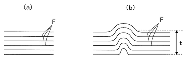
- the meandering amount device amount
- the amount of deviation of the fibers when the unidirectional continuous fibers F,... In the state before meandering in FIG. Measurement can be performed in a direction perpendicular to the initial fiber orientation direction (meandering amount tmm).
- the physical properties (tensile strength) of the UD material is reduced by about 10% when the continuous fiber meanders and the angle is shifted by 3 degrees, and by 50% when the angle is shifted by 12 degrees.
- Patent Document 1 a recess is provided at the boundary between a location where the continuous fiber reinforcing material in one direction is provided on the surface and the other location (the cavity surface has a projection for forming this recess), thereby An invention is disclosed that suppresses the orientation deviation of the continuous fibers constituting the continuous fiber reinforcing material.
- Patent Document 1 has a problem that the boundary becomes thin as much as the concave portion of the cavity, and this becomes a stress concentration portion when acting on an external force and easily becomes a failure starting point.
- the continuous fiber reinforcement temporarily installed on the cavity surface of the upper mold is likely to drop when the mold is closed, and it is difficult to obtain a molded product in which the continuous fiber reinforcement is embedded on the surface.
- the present invention has been made in view of the above-described problems. While eliminating the misalignment of the continuous fibers constituting the continuous fiber reinforcing material, the structure becomes weak at the boundary between the place where the continuous fiber is embedded and other places. It is not necessary to provide a recess, and the expected properties of continuous fiber reinforcement are obtained by using a mold that is used to mold fiber reinforced resin materials that guarantee the expected physical properties (such as tensile strength) of continuous fiber reinforcement. It aims at providing the manufacturing method of the fiber reinforced resin material which can manufacture the high intensity
- a method for producing a fiber reinforced resin material according to the present invention is a molding die in which a lower die and an upper die are closed to define a cavity, and the cavity is formed inside the lower die.
- a method of manufacturing a fiber reinforced resin material using a molding die provided with a groove portion communicating with the core, a core slidably disposed in the groove portion, and a push-up means for pushing up the core The first step of arranging the continuous fiber reinforcement on the core, charging the softened or melted matrix resin in the cavity, and pushing up the core with the lifting means to embed the continuous fiber reinforcement in the matrix resin, This is a second step of manufacturing a fiber reinforced resin material in which a continuous fiber reinforcing material is embedded in a cured matrix resin.
- the molding die used in the manufacturing method of the present invention has a groove that faces the cavity formed in the lower mold constituting the mold, and the core is slidably provided inside the lower mold, and continuously on the core.
- This is a mold in which a fiber reinforcing material can be placed and pushed up into the cavity, and the continuous fiber reinforcing material can be pushed into the resin charged in the cavity.
- a continuous fiber reinforcement is placed on the core.
- the pushing-up means for pushing up the core is made up of an actuator such as a servo motor and a feed screw mechanism that reciprocates up and down by the operation of the actuator, a fluid pressure in a hydraulic cylinder or an air cylinder, a magnetostrictive actuator, or a giant magnetostrictive actuator.
- an actuator such as a servo motor and a feed screw mechanism that reciprocates up and down by the operation of the actuator
- a fluid pressure in a hydraulic cylinder or an air cylinder a magnetostrictive actuator, or a giant magnetostrictive actuator.
- a reciprocating piston rod There are various embodiments such as a reciprocating piston rod.
- a plurality of recesses are provided at appropriate positions of the lower mold, the cores are accommodated in the respective recesses, and the plurality of cores are pushed up by the lifting means to spread the plurality of continuous fiber reinforcing materials in the cavity.
- the form embedded in a thermoplastic resin may be sufficient.
- a continuous fiber reinforcing material is disposed on the concave surface of the lower mold, and in the second step, the softened or melted thermoplastic resin is formed. Charged.
- charging includes both injecting molten resin into the cavity and placing a lump of molten resin or a sheet (preheated pre-shaped body) into the cavity. Then, a cavity-shaped resin member is formed by, for example, pressing the upper mold into the lower mold and performing press molding.
- the short fiber and the long fiber may be contained discontinuously in the thermoplastic resin to be charged.
- the fiber reinforced resin material to be manufactured is a vehicle skeleton structure member
- the fiber material is contained.
- a thermoplastic resin is charged.
- the softened or melted thermoplastic resin is charged in the cavity, and after the thermoplastic resin spreads in the cavity, the push-up means is operated to push up the continuous fiber reinforcing material. Can be pushed into the thermoplastic resin spreading in the cavity.
- Softening or melting of a thermoplastic resin means that when the thermoplastic resin is made of an amorphous plastic, “softening” is applied to the state exceeding the glass transition point Tg, and the thermoplastic resin is crystalline. In the case of plastic, “melting” is applied to the state exceeding the melting point Tm.
- Non-crystalline plastics that have a very low degree of crystallinity or cannot be crystallized include polystyrene (PS), polyvinyl chloride (PVC), polymethyl methacrylate (PMMA), ABS resin, thermoplastic epoxy, etc. Can be mentioned.
- PS polystyrene
- PVC polyvinyl chloride
- PMMA polymethyl methacrylate
- ABS resin thermoplastic epoxy
- crystalline plastics having high crystallinity include polyethylene (PE), polypropylene (PP), nylon (PA: nylon 6, nylon 66). Etc.), polyacetal (POM), polyethylene terephthalate (PET) and the like.
- the continuous fiber reinforcing material examples include a reinforcing material formed only from continuous fibers and a reinforcing material (prepreg material) in which continuous fibers are contained in a matrix resin.
- the continuous fiber reinforcing material may be a unidirectional material (UD material) in which a fiber material (continuous fiber) exceeding 50 mm is oriented in one direction in the matrix resin as defined in JIS, for example. It may be an isotropic material (such as a multi-axis laminated material or a woven fabric made of warp and weft).
- the continuous fibers include ceramic fibers such as boron, alumina, silicon carbide, silicon nitride, and zirconia, inorganic fibers such as glass fibers and carbon fibers, metal fibers such as copper, steel, aluminum, and stainless steel, and organic fibers such as polyamide and polyester. Any one kind of fibers or a mixed material of two or more kinds can be mentioned.
- the continuous fiber reinforcing material placed on the core is not disturbed in the process in which the softened or melted thermoplastic resin spreads in the cavity. Therefore, the orientation of the continuous fibers constituting the continuous fiber reinforcing material is The desired orientation can be maintained.
- the continuous fiber reinforcing material having the continuous fibers in which the desired orientation is maintained can be heated, for example. It can be embedded in a plastic resin.
- the same material as the thermoplastic resin charged on the surface of the continuous fiber reinforcing material is used to further guarantee the orientation of the continuous fiber of the continuous fiber reinforcing material positioned below the cavity when charging the thermoplastic resin.
- a measure such as keeping a sheet made of the thermoplastic resin in close contact may be taken.
- an ultra-thin protective plate is provided that defines a cavity and a groove and is slidably accommodated in the lower mold.
- a continuous continuous fiber reinforcement is provided below the protective plate. Is protected from the charged thermoplastic resin, and when the thermoplastic resin is sufficiently spread in the cavity, the protective plate slides so that the continuous fiber reinforcement faces the thermoplastic resin, and the push-up means is activated to continue.
- the molding die of the embodiment in which the fiber reinforcing material is embedded in the thermoplastic resin may be used.
- a heating means may be incorporated in the upper mold or the lower mold constituting the mold.
- the heating means can be operated to soften or melt the block or sheet.
- a fiber reinforced resin material obtained by embedding a continuous fiber reinforcing material at one or more desired locations and curing a thermoplastic resin as a matrix resin is the desired orientation of the continuous fibers that form the continuous fiber reinforcing material.
- the desired physical properties (such as tensile strength) of the continuous fiber reinforcing material are ensured, and a high-strength fiber-reinforced resin material is obtained.
- This fiber reinforced resin material is applied to non-structural members such as door outer panels and hoods as well as non-structural members such as door outer panels and hoods as well as vehicle skeleton structural members such as pillars, lockers, and floors under the floor. be able to.
- a fiber reinforced resin material of the present invention it is possible to guarantee the desired orientation of the continuous fibers constituting the continuous fiber reinforcing material that causes an increase in the strength of the fiber reinforced resin material.
- a high-strength fiber-reinforced resin material reinforced with a continuous fiber reinforcing material having physical properties (such as tensile strength) can be produced.
- the lower mold of the mold has a groove facing the cavity and a core slidable in the groove.
- the desired orientation of the continuous fibers constituting the continuous fiber reinforcement by embedding the continuous fiber reinforcement placed on the core by sliding the core after the thermoplastic resin spreads in Therefore, it is possible to manufacture a high-strength fiber reinforced resin material reinforced with a continuous fiber reinforcing material having an appropriate physical property (such as tensile strength).
- FIG. 1 It is the schematic diagram which showed one Embodiment of the shaping
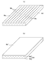
- (A) is the perspective view which showed one Embodiment of the continuous fiber reinforcement material
- (b) is the perspective view which showed other embodiment of the continuous fiber reinforcement material. It is the figure explaining the state in which the lump of the thermoplastic resin which fuse
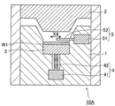
- FIG. 1 is a schematic diagram showing an embodiment of a molding die used in the manufacturing method of the present invention, and shows a state where an upper die and a lower die constituting the molding die are opened.
- the illustrated mold 10 includes an upper mold 2 and a lower mold 1, and defines a cavity K when both molds are closed.
- the lower mold 1 is formed with a groove portion 1a communicating with the cavity K, and a core 3 is slidably disposed in the groove portion 1a. Are pushed up to the cavity K side.
- the push-up means 4 shown in the figure is composed of a servo motor 41 and a rotating shaft 42 that is rotated by driving the servo motor 41, and the core 3 can be raised and lowered like a feed screw in accordance with the rotation of the rotating shaft 3. It is configured.
- the push-up means is not limited to the illustrated example, and includes a hydraulic cylinder, an air cylinder, an actuator such as a magnetostrictive actuator or a giant magnetostrictive actuator, and a piston rod that reciprocates by these actuators. May be fixed.
- the groove depth of the groove portion 1a is such that the upper surface of the continuous fiber reinforcing material W1 is the virtual lower surface of the cavity K in the posture in which the continuous fiber reinforcing material W1 is placed on the core 3 (dashed line in the figure).
- the groove depth is positioned lower than ⁇ .
- the continuous fiber reinforcing material W1 is placed in the groove portion 1a so as to fall below the virtual lower surface of the cavity K, so that the softened or melted thermoplastic resin is charged in the cavity K and spreads in the cavity K. In this case, the thermoplastic resin can be prevented from coming into contact with the continuous fiber reinforcing material W1 and disturbing the orientation of the continuous fibers.
- the continuous fiber reinforcing material W1 placed on the core 3 is used to reinforce a proper position of the fiber reinforced resin material finally obtained by being embedded in the thermoplastic resin charged in the cavity K.
- the form is such that the unidirectional material (UD material) in which the continuous fibers Wb are oriented in one direction in the matrix resin Wa, or the pseudo isotropic material (the direction material in the 0 degree direction and the direction material in the 90 degree direction).
- Directional material direction material in the direction of ⁇ 45 degrees
- multiaxial laminated material in which a plurality of direction materials such as direction materials in the directions of 0 degrees, 90 degrees, and ⁇ 45 degrees are laminated
- woven material made of warp and weft
- the upper surface of the continuous fiber reinforcing material W1 shown in FIG. 2b may be in close contact. Since the continuous fiber reinforcing material W1 includes the sheet Wa 'on the upper surface, it is possible to further ensure the orientation of the continuous fiber Wb when the thermoplastic resin is charged in the cavity K.
- ceramic fibers such as boron, alumina, silicon carbide, silicon nitride, and zirconia
- inorganic fibers such as glass fibers and carbon fibers
- metal fibers such as copper, steel, aluminum, and stainless steel
- polyamide One kind of organic fibers such as polyester or a mixture of two or more kinds can be mentioned.
- step S1 When the continuous fiber reinforcing material W1 is placed on the core 3 as shown in FIG. 1 (step S1), the softened or melted thermoplastic resin W2 ′ is charged in the cavity K as shown in FIG. Is done.
- thermoplastic resin W2 ′ For this charge, a method of injecting a softened or melted thermoplastic resin W2 ′ into the cavity K, a softened or melted thermoplastic resin W2 ′ lump or sheet is accommodated in the cavity K, and then the upper mold 2 is There is a method of pressing and pressing.
- the molding die 10 may include a heating means such as a far infrared heater (not shown).
- a heating means such as a far infrared heater (not shown).
- the heating means is operated, The thermoplastic resin can be softened or melted in the cavity K.
- thermoplastic resins there are a wide variety of thermoplastic resins to be charged.
- the thermoplastic resin is made of an amorphous plastic, the one that has been softened beyond its glass transition point Tg is charged, and when the thermoplastic resin is a crystalline plastic, What has melted beyond the melting point Tm is charged.
- non-crystalline plastic examples include polystyrene (PS), polyvinyl chloride (PVC), polymethyl methacrylate (PMMA), ABS resin, thermoplastic epoxy, and the like.
- Polycrystalline plastic includes polyethylene. (PE), polypropylene (PP), nylon (PA: nylon 6, nylon 66, etc.), polyacetal (POM), polyethylene terephthalate (PET), and the like.
- thermoplastic resin to be charged is the short fiber of the fiber material exemplified above when the fiber reinforced resin material finally obtained is a skeleton structure member of a vehicle that requires strength such as pillars, lockers, and floors under the floor. And a fiber resin material containing long fibers.
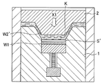
- thermoplastic resin W2 ′ As shown in FIG. 2, in the state where the softened or melted thermoplastic resin W2 ′ is accommodated in the cavity K, a gap S is formed between the upper surface of the continuous fiber reinforcing material W1 and the thermoplastic resin W2 ′. Both contacts are suppressed.
- the upper mold 2 is pushed into the lower mold 1 side by driving means (not shown) (X1 direction), so that the softened or melted thermoplastic resin W2 'is expanded in the cavity K. Even in the state where the thermoplastic resin W2 ′ is expanded in the cavity K in this way, there is a gap S ′ between this and the continuous fiber reinforcing material W1, and the interference between the two is suppressed, and the continuous fiber Wb The orientation is not disturbed.
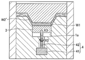
- the servo motor 41 When the thermoplastic resin W2 ′ sufficiently spreads in the cavity K, the servo motor 41 is operated to rotate the rotating shaft 42 (X2 direction) as shown in FIG. 5, and the core 3 is rotated according to the rotation of the rotating shaft 42. Is raised (X3 direction), the continuous fiber reinforcing material W1 placed on the core 3 is embedded in the thermoplastic resin W2 ′.
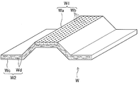
- thermoplastic resin W2 ′ When the thermoplastic resin W2 ′ is cured and the mold 10 in the mold closing position is opened to remove the molded product, short fibers or long fibers are formed in the matrix resin Wc made of the thermoplastic resin as shown in FIG.
- the fiber reinforced resin material W in which the continuous fiber reinforcing material W1 is embedded in a part of the fiber reinforced resin member in which the fiber material Wd such as fiber is embedded can be manufactured (step S2).
- the illustrated fiber reinforced resin material W is a part of a vehicle skeleton structure member reinforced with a continuous fiber reinforcing material W1, and the continuous fiber Wb is guaranteed to have an intended orientation in the manufacturing process described above. As a result, it becomes a high-strength fiber-reinforced resin material in which the expected physical properties of the continuous fiber reinforcing material W1 are guaranteed.
- FIG. 7 As the mold used in the manufacturing method of the present invention, another embodiment shown in FIG. 7 can be applied.
- the lower mold 1 is provided with a shielding means 5 including a protective plate 52 and a cylinder mechanism 51 for sliding the protective plate 52.
- the protective plate 52 When charging the thermoplastic resin, the protective plate 52 is connected to the cavity K.
- the groove 1a is defined to protect the continuous fiber reinforcing material W1 from the charged thermoplastic resin, and when the thermoplastic resin has sufficiently spread in the cavity K, the cylinder mechanism 51 is operated to slide the protective plate 52.
- (X4 direction) is a mold according to an embodiment in which the continuous fiber reinforcing material W1 is made to face the thermoplastic resin and the push-up means 4 is operated to embed the continuous fiber reinforcing material W1 in the thermoplastic resin.
- the inventors of the present invention manufactured a fiber reinforced resin material by the manufacturing method of the present invention using the mold having the above-described core (Example), and used a conventional mold without the core. Then, a fiber reinforced resin material was manufactured (comparative example), and an experiment was conducted to measure the meandering amount of continuous fibers of the continuous fiber reinforcing material embedded in both fiber reinforced resin materials.
- a UD material in which carbon fiber of 24 k is contained in a polypropylene matrix resin is used as a continuous fiber reinforcing material, and this is preliminarily set at about 200 to 250 ° C. with a far-infrared heater. What was preheated for about minutes was placed in a mold.
- the continuous fiber reinforcement was pressed at 20 MPa or higher, and the molten matrix resin was pressed at 10 MPa or higher.
- the meandering amount of the continuous fiber of the continuous fiber reinforcing material of both the example and the comparative example was 5 to 10 mm, whereas the meandering amount of the continuous fiber of the example was 5 to 10 mm.
Landscapes
- Engineering & Computer Science (AREA)
- Mechanical Engineering (AREA)
- Chemical & Material Sciences (AREA)
- Composite Materials (AREA)
- Casting Or Compression Moulding Of Plastics Or The Like (AREA)
- Moulding By Coating Moulds (AREA)
Abstract
Description
本発明者等は、上記する中子を具備する成形型を使用してなる本発明の製造方法によって繊維強化樹脂材を製造するとともに(実施例)、中子を具備しない従来の成形型を用いて繊維強化樹脂材を製造し(比較例)、双方の繊維強化樹脂材内に埋設された連続繊維補強材の連続繊維の蛇行量を測定する実験をおこなった。
Claims (3)
- 下型と上型が型閉めされてキャビティを画成する成形型であって、下型の内部に形成されて前記キャビティに連通する溝部と、溝部内に摺動自在に配設された中子と、中子を押上げる押上げ手段を備えた成形型を使用して繊維強化樹脂材を製造する方法であって、
連続繊維補強材を中子の上に配す第1のステップ、
キャビティ内に軟化もしくは溶融したマトリックス樹脂をチャージし、押上げ手段で中子を押し上げて連続繊維補強材をマトリックス樹脂内に埋め込み、硬化したマトリックス樹脂内に連続繊維補強材が埋設されてなる繊維強化樹脂材を製造する第2のステップからなる繊維強化樹脂材の製造方法。 - 前記連続繊維補強材は、連続繊維のみから形成された補強材、もしくは連続繊維がマトリックス樹脂内に含有されてなる補強材のいずれか一種からなる請求項1に記載の繊維強化樹脂材の製造方法。
- 前記マトリックス樹脂内に短繊維もしくは長繊維が含有されている請求項1または2に記載の繊維強化樹脂材の製造方法。
Priority Applications (5)
| Application Number | Priority Date | Filing Date | Title |
|---|---|---|---|
| JP2012530040A JP5418684B2 (ja) | 2011-03-08 | 2011-03-08 | 繊維強化樹脂材の製造方法 |
| US13/981,269 US8871127B2 (en) | 2011-03-08 | 2011-03-08 | Method of producing a fiber-reinforced resin member |
| CN201180065351.5A CN103328191B (zh) | 2011-03-08 | 2011-03-08 | 纤维强化树脂材料的制造方法 |
| DE112011105014.3T DE112011105014B4 (de) | 2011-03-08 | 2011-03-08 | Verfahren zum Herstellen eines faserverstärkten Kunstharzteils |
| PCT/JP2011/055303 WO2012120628A1 (ja) | 2011-03-08 | 2011-03-08 | 繊維強化樹脂材の製造方法 |
Applications Claiming Priority (1)
| Application Number | Priority Date | Filing Date | Title |
|---|---|---|---|
| PCT/JP2011/055303 WO2012120628A1 (ja) | 2011-03-08 | 2011-03-08 | 繊維強化樹脂材の製造方法 |
Publications (1)
| Publication Number | Publication Date |
|---|---|
| WO2012120628A1 true WO2012120628A1 (ja) | 2012-09-13 |
Family
ID=46797634
Family Applications (1)
| Application Number | Title | Priority Date | Filing Date |
|---|---|---|---|
| PCT/JP2011/055303 Ceased WO2012120628A1 (ja) | 2011-03-08 | 2011-03-08 | 繊維強化樹脂材の製造方法 |
Country Status (5)
| Country | Link |
|---|---|
| US (1) | US8871127B2 (ja) |
| JP (1) | JP5418684B2 (ja) |
| CN (1) | CN103328191B (ja) |
| DE (1) | DE112011105014B4 (ja) |
| WO (1) | WO2012120628A1 (ja) |
Cited By (5)
| Publication number | Priority date | Publication date | Assignee | Title |
|---|---|---|---|---|
| JP2015143007A (ja) * | 2013-12-03 | 2015-08-06 | ザ・ボーイング・カンパニーTheBoeing Company | ハイブリッド積層体及び成形複合構造体 |
| EP2946903A4 (en) * | 2013-01-21 | 2016-10-12 | Japan Steel Works Ltd | METHOD FOR PRODUCING A FIBER-REINFORCED RESIN COMPOSITE OR A RESIN FORMING AND SOFT EMPOWERING EXTRACTOR USED IN THIS MANUFACTURING METHOD |
| JP2018525258A (ja) * | 2015-08-18 | 2018-09-06 | ヘクセル ランフォルセマン エスアエス | 成形における改良又は成形に関連する改良 |
| JP2023507429A (ja) * | 2019-12-20 | 2023-02-22 | アルケマ フランス | 異なる補強性を有する2つのゾーンを含むポリマー複合組成物、その製造方法、その使用およびそれを含む物品 |
| JP2023535308A (ja) * | 2020-07-31 | 2023-08-17 | ニコベンチャーズ トレーディング リミテッド | エアロゾル供給システム用の消耗品 |
Families Citing this family (18)
| Publication number | Priority date | Publication date | Assignee | Title |
|---|---|---|---|---|
| DE102013223519A1 (de) * | 2013-11-19 | 2015-05-21 | Bayerische Motoren Werke Aktiengesellschaft | Faserkunststoffverbundbauteil und Verfahren zum Herstellen eines Faserkunststoffverbundbauteils, insbesondere eines Karosseriebauteils für ein Kraftfahrzeug |
| JP5959558B2 (ja) * | 2014-03-13 | 2016-08-02 | アイシン高丘株式会社 | 複合構造体及びその製造方法 |
| DE102014206500B4 (de) | 2014-04-04 | 2024-10-31 | Bayerische Motoren Werke Aktiengesellschaft | Werkzeug zur Herstellung eines Faserverbundbauteils |
| DE102014206904A1 (de) | 2014-04-10 | 2015-10-15 | Bayerische Motoren Werke Aktiengesellschaft | Verfahren und Vorrichtung zur Herstellung eines faserverstärkten Formbauteils |
| FR3024387B1 (fr) * | 2014-08-01 | 2017-03-10 | Plastic Omnium Cie | Moule pour la fabrication de piece en matiere plastique comportant un systeme de compression optimise |
| US10081140B2 (en) * | 2014-10-29 | 2018-09-25 | The Boeing Company | Apparatus for and method of compaction of a prepreg |
| DE102015200763B4 (de) * | 2015-01-20 | 2024-06-13 | Bayerische Motoren Werke Aktiengesellschaft | Verfahren und Werkzeug zur Herstellung eines Faserverbund-Bauteils |
| DE102015201559A1 (de) * | 2015-01-29 | 2016-08-04 | Bayerische Motoren Werke Aktiengesellschaft | Nasspressverfahren und Presswerkzeug hierfür |
| US10223481B2 (en) | 2015-04-14 | 2019-03-05 | Honda Motor Co., Ltd | Computer-aided resin behavior analyzer |
| CN104816660A (zh) * | 2015-04-30 | 2015-08-05 | 郑州翎羽新材料有限公司 | 一种高强度热塑性复合塑料座椅部件及其制备方法 |
| CN105128352A (zh) * | 2015-09-15 | 2015-12-09 | 北京博简复才技术咨询有限公司 | 复合材料集成结构和复合材料集成结构的制造方法 |
| DE102017001912A1 (de) | 2017-02-28 | 2018-08-30 | Audi Ag | Verfahren zur Herstellung eines Faserkunststoffverbundbauteils aus Prepreg- und SMC-Material |
| US20180345604A1 (en) | 2017-06-02 | 2018-12-06 | Arris Composites Llc | Aligned fiber reinforced molding |
| CN107364154B (zh) * | 2017-08-24 | 2019-02-22 | 陕西科技大学 | 一种纤维可控排布增强复合材料的制备装置及方法 |
| CN109624350B (zh) * | 2017-10-09 | 2023-09-12 | 苏州复盈新材股份有限公司 | 一种笔记本外壳的制造模具及其制造方法 |
| DE102018209935A1 (de) * | 2018-06-20 | 2019-12-24 | Bayerische Motoren Werke Aktiengesellschaft | Verbundstruktur für ein Fahrzeug, Fahrzeug mit der Verbundstruktur und Verfahren zum Herstellen der Verbundstruktur |
| US12226961B2 (en) * | 2018-10-12 | 2025-02-18 | Arris Composites Inc. | Preform charges and fixtures therefor |
| CN114585500A (zh) * | 2019-11-14 | 2022-06-03 | 美国圣戈班性能塑料公司 | 用于长纤维材料所制成的组件的预成型件、工具以及工艺设计 |
Citations (8)
| Publication number | Priority date | Publication date | Assignee | Title |
|---|---|---|---|---|
| JPS63233827A (ja) * | 1987-03-24 | 1988-09-29 | 東洋ゴム工業株式会社 | ポリウレタンフオ−ム成形品及びその製造方法 |
| JPH04215772A (ja) * | 1990-12-13 | 1992-08-06 | Yokohama Rubber Co Ltd:The | ゴルフクラブヘッドの製造方法 |
| JPH05261775A (ja) * | 1992-03-24 | 1993-10-12 | Nissan Motor Co Ltd | 樹脂パネルの成形装置 |
| JPH0872078A (ja) * | 1994-08-31 | 1996-03-19 | Araco Corp | 加飾体を備えた積層体の製造装置 |
| JPH09254199A (ja) * | 1996-03-25 | 1997-09-30 | Kanto Auto Works Ltd | ドアトリム成形装置 |
| JPH10138354A (ja) * | 1996-11-08 | 1998-05-26 | Yamaha Corp | 炭素繊維強化樹脂成形物とその製造方法 |
| JPH11198175A (ja) * | 1998-01-16 | 1999-07-27 | Idemitsu Petrochem Co Ltd | 表皮付樹脂成形品の製造方法および表皮付樹脂成形品 |
| JP2002355870A (ja) * | 2001-05-31 | 2002-12-10 | T S Tec Kk | 車両用内装部品の加飾成形装置及び加飾成形方法 |
Family Cites Families (12)
| Publication number | Priority date | Publication date | Assignee | Title |
|---|---|---|---|---|
| US2527063A (en) * | 1944-07-03 | 1950-10-24 | Gen Refractories Co | Process of making refractory brick for use in suspended furnace roofs |
| US2902721A (en) * | 1955-08-08 | 1959-09-08 | Gen Refractories Co | Process of molding refractory brick |
| US3813763A (en) * | 1970-12-17 | 1974-06-04 | Gen Electric | Laminated structure with insulating member formed in situ thereon and method for making same |
| US4334339A (en) * | 1980-05-12 | 1982-06-15 | Hollymatic Corporation | Mold device with movable compression insert |
| JPH0585179A (ja) | 1991-09-30 | 1993-04-06 | Aisin Seiki Co Ltd | 強化樹脂成形品 |
| FR2702067B1 (fr) * | 1993-02-23 | 1995-04-14 | Schlumberger Ind Sa | Procédé et dispositif de fabrication de cartes à mémoire. |
| JPH06254984A (ja) | 1993-03-08 | 1994-09-13 | Sekisui Chem Co Ltd | 繊維強化熱可塑性樹脂成形体の製造方法 |
| DE4435802A1 (de) * | 1994-10-06 | 1996-04-11 | Giesecke & Devrient Gmbh | Verfahren zur Herstellung von Datenträgern mit eingebetteten Elementen und Vorrichtung zur Durchführung des Verfahrens |
| EP0913791A1 (en) * | 1997-10-30 | 1999-05-06 | Navitas Co., Limited | Method for manufacturing card product and manufacturing apparatus therefor |
| ES2271585T3 (es) * | 2002-06-21 | 2007-04-16 | Weidmann Plastics Technology Ag | Procedimiento para fabricar un producto fabricado segun este procedimiento. |
| JP5416341B2 (ja) * | 2007-03-12 | 2014-02-12 | 新日鉄住金マテリアルズ株式会社 | 丸形状繊維強化プラスチック線材の製造方法 |
| JP5045330B2 (ja) | 2007-09-21 | 2012-10-10 | 東レ株式会社 | 繊維強化プラスチック構造体の製造方法 |
-
2011
- 2011-03-08 CN CN201180065351.5A patent/CN103328191B/zh not_active Expired - Fee Related
- 2011-03-08 WO PCT/JP2011/055303 patent/WO2012120628A1/ja not_active Ceased
- 2011-03-08 JP JP2012530040A patent/JP5418684B2/ja not_active Expired - Fee Related
- 2011-03-08 DE DE112011105014.3T patent/DE112011105014B4/de not_active Expired - Fee Related
- 2011-03-08 US US13/981,269 patent/US8871127B2/en active Active
Patent Citations (8)
| Publication number | Priority date | Publication date | Assignee | Title |
|---|---|---|---|---|
| JPS63233827A (ja) * | 1987-03-24 | 1988-09-29 | 東洋ゴム工業株式会社 | ポリウレタンフオ−ム成形品及びその製造方法 |
| JPH04215772A (ja) * | 1990-12-13 | 1992-08-06 | Yokohama Rubber Co Ltd:The | ゴルフクラブヘッドの製造方法 |
| JPH05261775A (ja) * | 1992-03-24 | 1993-10-12 | Nissan Motor Co Ltd | 樹脂パネルの成形装置 |
| JPH0872078A (ja) * | 1994-08-31 | 1996-03-19 | Araco Corp | 加飾体を備えた積層体の製造装置 |
| JPH09254199A (ja) * | 1996-03-25 | 1997-09-30 | Kanto Auto Works Ltd | ドアトリム成形装置 |
| JPH10138354A (ja) * | 1996-11-08 | 1998-05-26 | Yamaha Corp | 炭素繊維強化樹脂成形物とその製造方法 |
| JPH11198175A (ja) * | 1998-01-16 | 1999-07-27 | Idemitsu Petrochem Co Ltd | 表皮付樹脂成形品の製造方法および表皮付樹脂成形品 |
| JP2002355870A (ja) * | 2001-05-31 | 2002-12-10 | T S Tec Kk | 車両用内装部品の加飾成形装置及び加飾成形方法 |
Cited By (9)
| Publication number | Priority date | Publication date | Assignee | Title |
|---|---|---|---|---|
| EP2946903A4 (en) * | 2013-01-21 | 2016-10-12 | Japan Steel Works Ltd | METHOD FOR PRODUCING A FIBER-REINFORCED RESIN COMPOSITE OR A RESIN FORMING AND SOFT EMPOWERING EXTRACTOR USED IN THIS MANUFACTURING METHOD |
| CN109228408A (zh) * | 2013-01-21 | 2019-01-18 | 株式会社日本制钢所 | 纤维强化的树脂基材或树脂成形体的制造方法以及该制造方法中使用的塑化吐出机 |
| US10442143B2 (en) | 2013-01-21 | 2019-10-15 | The Japan Steel Works, Ltd. | Manufacturing method for fibre-reinforced resin substrate or resin molded article |
| CN109228408B (zh) * | 2013-01-21 | 2021-04-16 | 株式会社日本制钢所 | 纤维强化的树脂基材或树脂成形体的制造方法以及该制造方法中使用的塑化吐出机 |
| JP2015143007A (ja) * | 2013-12-03 | 2015-08-06 | ザ・ボーイング・カンパニーTheBoeing Company | ハイブリッド積層体及び成形複合構造体 |
| JP2018525258A (ja) * | 2015-08-18 | 2018-09-06 | ヘクセル ランフォルセマン エスアエス | 成形における改良又は成形に関連する改良 |
| JP2023507429A (ja) * | 2019-12-20 | 2023-02-22 | アルケマ フランス | 異なる補強性を有する2つのゾーンを含むポリマー複合組成物、その製造方法、その使用およびそれを含む物品 |
| JP2023535308A (ja) * | 2020-07-31 | 2023-08-17 | ニコベンチャーズ トレーディング リミテッド | エアロゾル供給システム用の消耗品 |
| JP7766076B2 (ja) | 2020-07-31 | 2025-11-07 | ニコベンチャーズ トレーディング リミテッド | エアロゾル供給システム用の消耗品 |
Also Published As
| Publication number | Publication date |
|---|---|
| JP5418684B2 (ja) | 2014-02-19 |
| CN103328191B (zh) | 2015-02-11 |
| US20130334734A1 (en) | 2013-12-19 |
| CN103328191A (zh) | 2013-09-25 |
| JPWO2012120628A1 (ja) | 2014-07-07 |
| US8871127B2 (en) | 2014-10-28 |
| DE112011105014T5 (de) | 2013-12-05 |
| DE112011105014B4 (de) | 2014-11-20 |
Similar Documents
| Publication | Publication Date | Title |
|---|---|---|
| JP5418684B2 (ja) | 繊維強化樹脂材の製造方法 | |
| JP5500177B2 (ja) | 繊維強化樹脂材とその製造方法 | |
| EP3310545B1 (de) | Verfahren zum herstellen eines kunststoffformkörpers, kunststoffformkörper und formwerkzeug | |
| US20120269999A1 (en) | Method for producing continuous-fiber-reinforced molded parts from thermoplastic plastic, and motor vehicle molded part | |
| CN103358462A (zh) | 用于制造复合或混杂结构的方法 | |
| JP2012240276A (ja) | 繊維強化樹脂材とその製造方法 | |
| JP2016506327A5 (ja) | ||
| KR20210107535A (ko) | 향상된 성능의 재생가능한 탄소섬유 강화 중합체 | |
| US20160114526A1 (en) | Method of connecting members | |
| JP6107787B2 (ja) | 繊維強化樹脂成形部材の製造方法と部材の接続方法 | |
| TW201533109A (zh) | 複合物的一次完成製法 | |
| JP5655746B2 (ja) | 繊維強化樹脂材の製造方法 | |
| JP5712857B2 (ja) | 繊維強化樹脂材の製造方法 | |
| CN101031420A (zh) | 用于汽车顶棚的可循环复合塑料 | |
| CN202507459U (zh) | 一种单聚合物复合材料制品注塑成型设备 | |
| KR20160045123A (ko) | 중합체 재료로 이루어진 부품의 제조 방법 | |
| Mubashir et al. | Carbon fibre composites: Outlook for the automobile sector | |
| JP2010522652A (ja) | 熱可塑性複合部品の成形による製造方法 | |
| CN105619837A (zh) | 一种汽车用预氧丝增强热塑性复合材料制品及其制备方法 | |
| Zaveri et al. | Current Applications and Advancements in the Manufacturing of Discontinuous Fiber Composites | |
| JP2013129064A (ja) | 繊維強化樹脂材の製造方法 | |
| EP3819120B1 (en) | Phosphorescent thermoplastic composite layered structure | |
| CN121670909A (zh) | 一种采用热塑性回收碳纤维毡板成型零部件的模具及方法 | |
| Yin et al. | Tongliang Du and Jun Chen | |
| Yin et al. | Experiment study of thermoforming of plain woven composite (carbon/thermoplastics) |
Legal Events
| Date | Code | Title | Description |
|---|---|---|---|
| ENP | Entry into the national phase |
Ref document number: 2012530040 Country of ref document: JP Kind code of ref document: A |
|
| 121 | Ep: the epo has been informed by wipo that ep was designated in this application |
Ref document number: 11860416 Country of ref document: EP Kind code of ref document: A1 |
|
| WWE | Wipo information: entry into national phase |
Ref document number: 13981269 Country of ref document: US |
|
| WWE | Wipo information: entry into national phase |
Ref document number: 112011105014 Country of ref document: DE Ref document number: 1120111050143 Country of ref document: DE |
|
| 122 | Ep: pct application non-entry in european phase |
Ref document number: 11860416 Country of ref document: EP Kind code of ref document: A1 |