WO2012120592A1 - 車両の冷却システム - Google Patents
車両の冷却システム Download PDFInfo
- Publication number
- WO2012120592A1 WO2012120592A1 PCT/JP2011/055070 JP2011055070W WO2012120592A1 WO 2012120592 A1 WO2012120592 A1 WO 2012120592A1 JP 2011055070 W JP2011055070 W JP 2011055070W WO 2012120592 A1 WO2012120592 A1 WO 2012120592A1
- Authority
- WO
- WIPO (PCT)
- Prior art keywords
- liquid medium
- pump
- cooling system
- flow rate
- temperature
- Prior art date
- Legal status (The legal status is an assumption and is not a legal conclusion. Google has not performed a legal analysis and makes no representation as to the accuracy of the status listed.)
- Ceased
Links
Images

Classifications
-
- F—MECHANICAL ENGINEERING; LIGHTING; HEATING; WEAPONS; BLASTING
- F01—MACHINES OR ENGINES IN GENERAL; ENGINE PLANTS IN GENERAL; STEAM ENGINES
- F01P—COOLING OF MACHINES OR ENGINES IN GENERAL; COOLING OF INTERNAL-COMBUSTION ENGINES
- F01P5/00—Pumping cooling-air or liquid coolants
- F01P5/14—Safety means against, or active at, failure of coolant-pumps drives, e.g. shutting engine down; Means for indicating functioning of coolant pumps
-
- B—PERFORMING OPERATIONS; TRANSPORTING
- B60—VEHICLES IN GENERAL
- B60L—PROPULSION OF ELECTRICALLY-PROPELLED VEHICLES; SUPPLYING ELECTRIC POWER FOR AUXILIARY EQUIPMENT OF ELECTRICALLY-PROPELLED VEHICLES; ELECTRODYNAMIC BRAKE SYSTEMS FOR VEHICLES IN GENERAL; MAGNETIC SUSPENSION OR LEVITATION FOR VEHICLES; MONITORING OPERATING VARIABLES OF ELECTRICALLY-PROPELLED VEHICLES; ELECTRIC SAFETY DEVICES FOR ELECTRICALLY-PROPELLED VEHICLES
- B60L1/00—Supplying electric power to auxiliary equipment of vehicles
- B60L1/003—Supplying electric power to auxiliary equipment of vehicles to auxiliary motors, e.g. for pumps, compressors
-
- B—PERFORMING OPERATIONS; TRANSPORTING
- B60—VEHICLES IN GENERAL
- B60L—PROPULSION OF ELECTRICALLY-PROPELLED VEHICLES; SUPPLYING ELECTRIC POWER FOR AUXILIARY EQUIPMENT OF ELECTRICALLY-PROPELLED VEHICLES; ELECTRODYNAMIC BRAKE SYSTEMS FOR VEHICLES IN GENERAL; MAGNETIC SUSPENSION OR LEVITATION FOR VEHICLES; MONITORING OPERATING VARIABLES OF ELECTRICALLY-PROPELLED VEHICLES; ELECTRIC SAFETY DEVICES FOR ELECTRICALLY-PROPELLED VEHICLES
- B60L3/00—Electric devices on electrically-propelled vehicles for safety purposes; Monitoring operating variables, e.g. speed, deceleration or energy consumption
-
- B—PERFORMING OPERATIONS; TRANSPORTING
- B60—VEHICLES IN GENERAL
- B60L—PROPULSION OF ELECTRICALLY-PROPELLED VEHICLES; SUPPLYING ELECTRIC POWER FOR AUXILIARY EQUIPMENT OF ELECTRICALLY-PROPELLED VEHICLES; ELECTRODYNAMIC BRAKE SYSTEMS FOR VEHICLES IN GENERAL; MAGNETIC SUSPENSION OR LEVITATION FOR VEHICLES; MONITORING OPERATING VARIABLES OF ELECTRICALLY-PROPELLED VEHICLES; ELECTRIC SAFETY DEVICES FOR ELECTRICALLY-PROPELLED VEHICLES
- B60L58/00—Methods or circuit arrangements for monitoring or controlling batteries or fuel cells, specially adapted for electric vehicles
- B60L58/10—Methods or circuit arrangements for monitoring or controlling batteries or fuel cells, specially adapted for electric vehicles for monitoring or controlling batteries
-
- F—MECHANICAL ENGINEERING; LIGHTING; HEATING; WEAPONS; BLASTING
- F01—MACHINES OR ENGINES IN GENERAL; ENGINE PLANTS IN GENERAL; STEAM ENGINES
- F01P—COOLING OF MACHINES OR ENGINES IN GENERAL; COOLING OF INTERNAL-COMBUSTION ENGINES
- F01P5/00—Pumping cooling-air or liquid coolants
- F01P5/10—Pumping liquid coolant; Arrangements of coolant pumps
-
- B—PERFORMING OPERATIONS; TRANSPORTING
- B60—VEHICLES IN GENERAL
- B60L—PROPULSION OF ELECTRICALLY-PROPELLED VEHICLES; SUPPLYING ELECTRIC POWER FOR AUXILIARY EQUIPMENT OF ELECTRICALLY-PROPELLED VEHICLES; ELECTRODYNAMIC BRAKE SYSTEMS FOR VEHICLES IN GENERAL; MAGNETIC SUSPENSION OR LEVITATION FOR VEHICLES; MONITORING OPERATING VARIABLES OF ELECTRICALLY-PROPELLED VEHICLES; ELECTRIC SAFETY DEVICES FOR ELECTRICALLY-PROPELLED VEHICLES
- B60L2240/00—Control parameters of input or output; Target parameters
- B60L2240/10—Vehicle control parameters
- B60L2240/36—Temperature of vehicle components or parts
-
- F—MECHANICAL ENGINEERING; LIGHTING; HEATING; WEAPONS; BLASTING
- F01—MACHINES OR ENGINES IN GENERAL; ENGINE PLANTS IN GENERAL; STEAM ENGINES
- F01P—COOLING OF MACHINES OR ENGINES IN GENERAL; COOLING OF INTERNAL-COMBUSTION ENGINES
- F01P2025/00—Measuring
- F01P2025/04—Pressure
- F01P2025/06—Pressure for determining flow
-
- F—MECHANICAL ENGINEERING; LIGHTING; HEATING; WEAPONS; BLASTING
- F01—MACHINES OR ENGINES IN GENERAL; ENGINE PLANTS IN GENERAL; STEAM ENGINES
- F01P—COOLING OF MACHINES OR ENGINES IN GENERAL; COOLING OF INTERNAL-COMBUSTION ENGINES
- F01P2031/00—Fail safe
-
- F—MECHANICAL ENGINEERING; LIGHTING; HEATING; WEAPONS; BLASTING
- F01—MACHINES OR ENGINES IN GENERAL; ENGINE PLANTS IN GENERAL; STEAM ENGINES
- F01P—COOLING OF MACHINES OR ENGINES IN GENERAL; COOLING OF INTERNAL-COMBUSTION ENGINES
- F01P2031/00—Fail safe
- F01P2031/36—Failure of coolant pump
-
- Y—GENERAL TAGGING OF NEW TECHNOLOGICAL DEVELOPMENTS; GENERAL TAGGING OF CROSS-SECTIONAL TECHNOLOGIES SPANNING OVER SEVERAL SECTIONS OF THE IPC; TECHNICAL SUBJECTS COVERED BY FORMER USPC CROSS-REFERENCE ART COLLECTIONS [XRACs] AND DIGESTS
- Y02—TECHNOLOGIES OR APPLICATIONS FOR MITIGATION OR ADAPTATION AGAINST CLIMATE CHANGE
- Y02T—CLIMATE CHANGE MITIGATION TECHNOLOGIES RELATED TO TRANSPORTATION
- Y02T10/00—Road transport of goods or passengers
- Y02T10/60—Other road transportation technologies with climate change mitigation effect
- Y02T10/70—Energy storage systems for electromobility, e.g. batteries
Definitions
- the present invention relates to a vehicle cooling system, and more particularly to a vehicle cooling system having a control device that identifies a defective portion of the cooling system.
- An example of a technique for determining a failure in a cooling system of a vehicle is an abnormality determination device described in Japanese Patent Laid-Open No. 2009-46077 (Patent Document 1).
- This abnormality determination device suppresses erroneous determination that determines that the electric water pump is abnormal although the driving state of the electric water pump is normal.
- the electronic control unit pumps the cooling water to the heater core provided in the water passage from the electric pump to the engine when the engine is stopped, and the cooling water temperature inside the heater core with respect to the cooling water temperature inside the engine. Is determined to be abnormal when the electric pump is in a driving state.
- the abnormality determination device disclosed in Japanese Patent Application Laid-Open No. 2009-46077 assumes a water pump abnormality as an abnormality in the cooling system. Even if an abnormality occurs in other parts, it is regarded as an abnormality of the water pump. It cannot be detected separately.
- the abnormality in the cooling system includes an abnormality in the control signal of the water pump, an abnormality occurring in the hardware of the water pump itself, an abnormality in the water passage, an abnormality in the heat dissipation system, and the like. For this reason, it took time and effort to specify the part of the failure at the time of repair.
- An object of the present invention is to provide a vehicle cooling system that can detect and detect abnormalities in the cooling system in more detail.
- the present invention provides a vehicle cooling system, a flow path for circulating a liquid medium for cooling a vehicle drive device, a flow rate detection unit for detecting a flow rate of the liquid medium flowing through the flow path, and a liquid medium
- a temperature sensor for detecting the temperature, a pump for circulating the liquid medium provided on the flow path, a rotation speed sensor for detecting the rotation speed of the pump, and a control device for controlling the drive of the pump are provided.
- the control device identifies a defective portion of the cooling system according to the flow rate of the liquid medium, the temperature of the liquid medium, and the rotational speed of the pump.
- the control device temporarily increases the rotation speed of the pump, and then the flow rate is normal. If the value does not recover, it is determined that the defective part is a flow path.
- the control device identifies that the defective part is the pump. To do.
- the cooling system further includes a radiator provided on the flow path and a fan for blowing air to the radiator.
- the control device detects heat generation or heat radiation abnormality based on the operating state of the fan and the inverter temperature.
- the abnormality of the cooling system can be distinguished and detected in more detail, so that the locations to be confirmed at the time of repair are limited and the work efficiency is improved.
- FIG. 1 is a circuit diagram showing a configuration of a vehicle 100 equipped with a vehicle cooling system. It is the figure which showed the relationship between the water flow resistance of a cooling system, and flow volume. It is the figure which showed the abnormality considered based on water temperature, the rotational speed of a pump, and a flow volume, and its verification method. It is a flowchart for demonstrating the diagnostic process performed with the control apparatus 30 of FIG.
- FIG. 1 is a circuit diagram showing a configuration of a vehicle 100 equipped with a vehicle cooling system.
- vehicle 100 includes a battery MB that is a power storage device, a voltage sensor 10, a power control unit (PCU) 40, a motor generator MG, and a control device 30.
- PCU 40 includes a voltage converter 12, smoothing capacitors C 1, CH, a voltage sensor 13, and an inverter 14.
- Vehicle 100 further includes a positive electrode bus PL2 that supplies power to inverter 14 that drives motor generator MG.
- the smoothing capacitor C1 is connected between the positive electrode bus PL1 and the negative electrode bus SL2.
- the voltage converter 12 boosts the voltage across the terminals of the smoothing capacitor C1.
- Smoothing capacitor CH smoothes the voltage boosted by voltage converter 12.
- the voltage sensor 13 detects the voltage VH between the terminals of the smoothing capacitor CH and outputs it to the control device 30.
- Vehicle 100 further includes system main relay SMRB connected between the positive electrode of battery MB and positive electrode bus PL1, and system main relay SMRG connected between the negative electrode of battery MB (negative electrode bus SL1) and node N2. Including.
- the system main relays SMRB and SMRG are controlled to be in a conductive / non-conductive state in accordance with a control signal SE given from the control device 30.
- the voltage sensor 10 measures the voltage VB between the terminals of the battery MB.
- a current sensor for detecting a current IB flowing through the battery MB is provided.
- the battery MB for example, a secondary battery such as a lead storage battery, a nickel metal hydride battery, or a lithium ion battery, or a large capacity capacitor such as an electric double layer capacitor can be used.
- the negative electrode bus SL2 extends through the voltage converter 12 to the inverter 14 side.
- the voltage converter 12 is a voltage converter that is provided between the battery MB and the positive electrode bus PL2 and performs voltage conversion. Voltage converter 12 is connected in parallel to reactor L1 whose one end is connected to positive electrode bus PL1, IGBT elements Q1, Q2 connected in series between positive electrode bus PL2 and negative electrode bus SL2, and IGBT elements Q1, Q2. And diodes D1 and D2 connected to each other.
- reactor L1 The other end of reactor L1 is connected to the emitter of IGBT element Q1 and the collector of IGBT element Q2.
- the cathode of diode D1 is connected to the collector of IGBT element Q1, and the anode of diode D1 is connected to the emitter of IGBT element Q1.
- the cathode of diode D2 is connected to the collector of IGBT element Q2, and the anode of diode D2 is connected to the emitter of IGBT element Q2.
- the inverter 14 is connected to the positive electrode bus PL2 and the negative electrode bus SL2. Inverter 14 converts the DC voltage output from voltage converter 12 into a three-phase AC voltage and outputs the same to motor generator MG driving wheel 2. Inverter 14 returns the electric power generated in motor generator MG to voltage converter 12 along with regenerative braking. At this time, the voltage converter 12 is controlled by the control device 30 so as to operate as a step-down circuit.
- the inverter 14 includes a U-phase arm 15, a V-phase arm 16, and a W-phase arm 17.
- U-phase arm 15, V-phase arm 16, and W-phase arm 17 are connected in parallel between positive electrode bus PL2 and negative electrode bus SL2.
- U-phase arm 15 includes IGBT elements Q3 and Q4 connected in series between positive electrode bus PL2 and negative electrode bus SL2, and diodes D3 and D4 connected in parallel with IGBT elements Q3 and Q4, respectively.
- the cathode of diode D3 is connected to the collector of IGBT element Q3, and the anode of diode D3 is connected to the emitter of IGBT element Q3.
- the cathode of diode D4 is connected to the collector of IGBT element Q4, and the anode of diode D4 is connected to the emitter of IGBT element Q4.
- V-phase arm 16 includes IGBT elements Q5 and Q6 connected in series between positive electrode bus PL2 and negative electrode bus SL2, and diodes D5 and D6 connected in parallel with IGBT elements Q5 and Q6, respectively.
- the cathode of diode D5 is connected to the collector of IGBT element Q5, and the anode of diode D5 is connected to the emitter of IGBT element Q5.
- the cathode of diode D6 is connected to the collector of IGBT element Q6, and the anode of diode D6 is connected to the emitter of IGBT element Q6.
- W-phase arm 17 includes IGBT elements Q7 and Q8 connected in series between positive electrode bus PL2 and negative electrode bus SL2, and diodes D7 and D8 connected in parallel with IGBT elements Q7 and Q8, respectively.
- the cathode of diode D7 is connected to the collector of IGBT element Q7, and the anode of diode D7 is connected to the emitter of IGBT element Q7.
- the cathode of diode D8 is connected to the collector of IGBT element Q8, and the anode of diode D8 is connected to the emitter of IGBT element Q8.
- the motor generator MG is a three-phase permanent magnet synchronous motor, and one end of each of the three stator coils of the U, V, and W phases is connected to a neutral point.
- the other end of the U-phase coil is connected to a line drawn from the connection node of IGBT elements Q3 and Q4.
- the other end of the V-phase coil is connected to a line drawn from the connection node of IGBT elements Q5 and Q6.
- the other end of the W-phase coil is connected to a line drawn from the connection node of IGBT elements Q7 and Q8.
- Current sensor 24 detects the current flowing through motor generator MG as motor current value MCRT and outputs motor current value MCRT to control device 30.
- Control device 30 receives each torque command value and rotation speed of motor generator MG, each value of current IB and voltages VB and VH, motor current value MCRT, and start signal IGON. Control device 30 outputs a control signal PWU for instructing voltage converter 12, a control signal PWD for instructing step-down, and a shutdown signal for instructing prohibition of operation.
- control device 30 generates a control signal PWMI for instructing inverter 14 to convert a DC voltage output from voltage converter 12 into an AC voltage for driving motor generator MG, and motor generator MG for power generation.
- a control signal PWMC for performing a regeneration instruction for converting the AC voltage thus converted into a DC voltage and returning it to the voltage converter 12 side is output.
- vehicle 100 includes a radiator 102, a reservoir tank 106, and a water pump 104 as a cooling system for cooling PCU 40 and motor generator MG.
- the radiator 102, the PCU 40, the reservoir tank 106, the water pump 104, and the motor generator MG are annularly connected in series via a water passage.
- a flow rate sensor 114 is provided in the water passage, and the flow rate FR is transmitted to the control device 30. Instead of the flow rate sensor 114, another method for estimating the flow rate of the cooling water may be used.
- the water pump 104 is a pump for circulating cooling water such as antifreeze and circulates cooling water in the direction of the arrow shown in the figure.
- the radiator 102 receives the cooling water after cooling the voltage converter 12 and the inverter 14 inside the PCU 40 from the water passage, and cools the received cooling water using the radiator fan 103.
- a temperature sensor 108 for measuring the cooling water temperature is provided in the vicinity of the cooling water inlet of the PCU 40.
- the cooling water temperature TW is transmitted from the temperature sensor 108 to the control device 30.
- a temperature sensor 110 that detects the temperature TC of the voltage converter 12 and a temperature sensor 112 that detects the temperature TI of the inverter 14 are provided inside the PCU 40.
- a temperature detection element or the like built in the intelligent power module is used as the temperature sensors 110 and 112, a temperature detection element or the like built in the intelligent power module is used.
- Control device 30 generates signal SP for driving water pump 104 based on temperature TC from temperature sensor 110 and temperature TI from temperature sensor 112, and outputs the generated signal SP to water pump 104. To do.
- a flow rate sensor 114 for detecting the flow rate of cooling water that has not been detected conventionally is provided.
- detecting the flow rate it is possible to specify a more detailed failure location as will be described with reference to FIG. 2 and subsequent drawings regarding failures that could conventionally only be determined as a cooling system abnormality. Even if the flow sensor 114 is not provided, the same effect can be obtained by estimating the flow rate by another method.
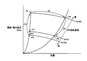
- FIG. 2 is a diagram showing the relationship between the water flow resistance of the cooling system and the flow rate.
- the water flow resistance (kPa) of the cooling system is shown on the vertical axis
- the flow rate (L / min) of the refrigerant such as cooling water is shown on the horizontal axis.
- the flow resistance (kPa) changes along a curve passing through the points P4 and P5 when the flow rate increases or decreases.
- the water passage resistance increases.
- the water flow resistance (kPa) changes along a curve passing through the points P1, P2, and P3.
- the control device 30 in FIG. 1 changes the control signal SP for the water pump 104 to increase the rotation speed to N3. If the foreign object remains sandwiched, the operating point moves to point P3 as indicated by arrow A2. Here, when the foreign matter is removed due to the increase of the water flow resistance, the flow rate is recovered and the operating point moves to the point P4 as indicated by the arrow A3. If the flow rate sensor can detect that the flow rate has recovered, the control device changes the control signal SP to the water pump 104 and returns the rotation speed to N1.
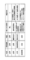
- FIG. 3 is a diagram showing a possible abnormality based on the water temperature, the rotational speed of the pump, and the flow rate, and a verification method thereof.
- the control device 30 temporarily changes the rotation of the water pump 104 and observes the flow rate change. And if the change of a flow rate is observed from the operating point P1 of FIG. 2 and an operating point moves along the line of the points P2 to P3, the control apparatus 30 will judge that water flow resistance has deteriorated. . In this case, the control device 30 attempts to improve the state in which the foreign matter is caught in the water passage and cannot move by increasing the rotation of the water pump 104 and moving the operating point to the point P3 side. When the foreign object moves and the flow rate returns to the original state, the control device 30 returns the rotational speed to the original state. If the flow rate does not return to the original state, the control device 30 determines a diagnosis (diagnosis) that the piping system is abnormal.
- diagnosis diagnosis
- the control device 30 observes the current of the water pump 104 and the temperature of the water pump 104, and determines that the abnormality is in the pump itself if abnormalities such as abnormal heat generation or overcurrent are recognized. If there is no abnormality in the current or temperature, the control device 30 determines that there is an abnormality in another cooling system.
- FIG. 3 shows a case in which the control device 30 includes a plurality of ECUs. In this case, the control device 30 performs an abnormality determination of the cooling system to the ECU that controls the radiator fan by communication between the ECUs. A command for changing the rotation speed of the fan is issued, or an ECU for determining abnormality of the cooling system is obtained from a motor ECU that directly controls the inverter and the converter.
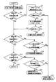
- FIG. 4 is a flowchart for explaining the diagnosis process executed by the control device 30 of FIG. The processing of this flowchart is called from the main routine and executed at regular time intervals or whenever a predetermined condition is satisfied.
- control device 30 reads water temperature TW from temperature sensor 108, reads rotation speed Np of water pump 104 from rotation sensor 105, The flow rate FR is read from the sensor 114.
- step S2 the control device 30 determines whether or not the condition that the water temperature TW is normal, the rotation speed Np is normal, and the flow rate FR is small is satisfied.
- “Normal” indicates that a numerical value is included between a predetermined upper limit value and a lower limit value, for example. Also, “less” means that the numerical value is smaller than the lower limit value of the normal predetermined range.
- step S2 If the condition of step S2 is satisfied, the process proceeds from step S2 to step S3.
- step S3 the control device 30 changes the control signal SP so as to temporarily reduce the rotational speed Np of the water pump 104.
- step S4 if the flow rate FR acquired from the flow rate sensor 114 does not decrease so as to cope with the decrease in rotational speed, the process proceeds to step S14. On the other hand, in step S4, when the flow rate FR acquired from the flow sensor 114 decreases to correspond to the decrease in rotation speed, the process proceeds to step S5.
- step S5 it is considered that the operating point in FIG. 2 has moved from point P1 to point P2.
- the failure is estimated to be a piping system abnormality (for example, the piping is clogged with foreign matter and the cross-sectional area is reduced).
- the rotational speed Np of the water pump 104 is temporarily increased to increase the flow rate, and the piping system abnormality (for example, foreign matter is clogged) is restored to the original state. Try that.
- step S6 the control device 30 determines whether or not the flow rate FR has recovered to a normal state. This can be done by checking whether the operating point is point P3 (abnormal) or point P4 (normal) in FIG. Since the rotational speed Np of the water pump 104 and the flow rate FR have a relationship indicated by a curve passing through the points P4 to P5 when normal, it is easy to determine a normal range of the flow rate FR with respect to the rotational speed Np.
- step S6 when the flow rate is restored to the normal flow rate, it is considered that the piping system abnormality has become normal. Therefore, the process merges with the case of “NO” in step S2, and the process proceeds to step S8. move on. On the other hand, if the flow rate does not recover in step S6, the process proceeds to step S7, and the diagnosis of the piping system abnormality is confirmed. The diagnosis result is notified to the driver on the spot, stored in a nonvolatile memory or the like, and later read out at a repair shop for analysis.
- step S8 the control device 30 determines whether or not the condition that the water temperature TW is normal, the rotational speed Np is low, and the flow rate FR is small is satisfied.
- “Normal” indicates that a numerical value is included between a predetermined upper limit value and a lower limit value, for example. Low and low indicate that the numerical value is smaller than the lower limit value of the normal predetermined range.
- step S8 If the condition of step S8 is satisfied, the process proceeds from step S8 to step S9. If the condition is not satisfied, the process proceeds to step S11.
- step S9 it is determined whether or not the current value abnormality of the water pump 104 or the internal temperature abnormality of the water pump 104 has occurred.
- An abnormality in the current value of the water pump 104 can be detected by providing a current sensor in the power supply line of the water pump 104. Further, the internal temperature of the water pump 104 can be detected by attaching a temperature sensor in or near the water pump 104.
- step S9 If neither the current value abnormality of the water pump 104 nor the internal temperature abnormality of the water pump 104 has occurred in step S9, the process proceeds to step S14. If the current value abnormality of the water pump 104 or the internal temperature abnormality of the water pump 104 has occurred in step S9, the process proceeds to step S10, and the diagnosis of the performance abnormality of the water pump 104 is confirmed. The diagnosis result is notified to the driver on the spot, stored in a nonvolatile memory or the like, and later read out at a repair shop for analysis.
- step S11 the control device 30 determines whether the condition that the water temperature TW is abnormal (high), the rotation speed Np is normal, and the flow rate FR is normal is satisfied.
- “Normal” indicates that a numerical value is included between a predetermined upper limit value and a lower limit value, for example. Further, “high” indicates that the numerical value is larger than the upper limit value of the normal predetermined range.
- step S11 If the condition of step S11 is satisfied, the process proceeds from step S11 to step S12. If the condition is not satisfied, the process proceeds to step S15. In step S15, since none of the conditions are met, a failure is not diagnosed and control is returned to the main routine.
- step S12 it is determined whether an operation abnormality of the radiator fan 103 or a heat generation abnormality of the inverter 14 has occurred.
- Abnormal operation of the radiator fan 103 can be determined by comparing the command value from the control device 30 with the rotational speed detected by the radiator fan 103.
- Abnormal heat generation of the inverter 14 can be determined by whether or not the temperature TI from the temperature sensor 112 incorporated in the inverter 14 exceeds a predetermined threshold value.
- step S12 when neither the radiator fan 103 malfunction nor the inverter 14 heat generation abnormality has occurred, the process proceeds to step S14. If any of the abnormal operation of the radiator fan 103 and the abnormal heat generation of the inverter 14 has occurred in step S12, the process proceeds to step S13, and the diagnosis of the heat dissipation abnormality or the heat generation abnormality is confirmed. The diagnosis result is notified to the driver on the spot, stored in a nonvolatile memory or the like, and later read out at a repair shop for analysis.
- step S14 a diagnosis of another abnormality of the cooling system (abnormalities other than those of steps S7, S10, and S13 among abnormality of the cooling system) is confirmed and notified to the driver on the spot. It is stored in a non-volatile memory or the like and later read out at a repair shop for analysis.
- the defective part of the cooling system is subdivided and specified by combining a new parameter such as the cooling water flow rate with the existing parameters such as the pump rotation speed and the cooling water temperature. be able to.
Landscapes
- Engineering & Computer Science (AREA)
- Mechanical Engineering (AREA)
- Power Engineering (AREA)
- Transportation (AREA)
- Chemical & Material Sciences (AREA)
- Combustion & Propulsion (AREA)
- General Engineering & Computer Science (AREA)
- Life Sciences & Earth Sciences (AREA)
- Sustainable Development (AREA)
- Sustainable Energy (AREA)
- Electric Propulsion And Braking For Vehicles (AREA)
- Cooling Or The Like Of Electrical Apparatus (AREA)
Abstract
Description
[駆動系の説明]
図1を参照して、車両100は、蓄電装置であるバッテリMBと、電圧センサ10と、パワーコントロールユニット(PCU)40と、モータジェネレータMGと、制御装置30とを含む。PCU40は、電圧コンバータ12と、平滑用コンデンサC1,CHと、電圧センサ13と、インバータ14とを含む。車両100は、モータジェネレータMGを駆動するインバータ14に給電を行なう正極母線PL2をさらに含む。
再び図1を参照して、車両100は、PCU40およびモータジェネレータMGを冷却する冷却系として、ラジエータ102と、リザーバータンク106と、ウォータポンプ104とを含む。
ウォータポンプ104は、不凍液などの冷却水を循環させるためのポンプであって、図示される矢印の方向に冷却水を循環させる。ラジエータ102は、PCU40内部の電圧コンバータ12およびインバータ14を冷却した後の冷却水を通水路から受け、その受けた冷却水をラジエータファン103を用いて冷却する。
図2を参照して、冷却系の通水抵抗(kPa)が縦軸に示され、冷却水などの冷媒の流量(L/min)が横軸に示されている。冷却系の通水抵抗と流量とが正常な関係であれば、流量が増減すると点P4と点P5を通る曲線に沿って通水抵抗(kPa)は変化する。しかし、冷却系の通水路などに異物(錆びなど)による詰まりが発生すると、通水抵抗は増加する。この場合、流量が増減すると、点P1,点P2および点P3を通る曲線に沿って通水抵抗(kPa)が変化する。
なお、図2中にはウォータポンプの回転速度と流量と通水抵抗との関係も示されている。回転速度N=N0の時に比べて、回転速度が高い回転速度N=N1の方が通水抵抗が増加し、さらに回転速度が高い回転速度N=N3の方が通水抵抗がさらに増加することが示されている。
図3は、水温とポンプの回転速度と流量とにもとづいて考えられる異常とその検証方法を示した図である。
また、図3の第4行目に示されるように、水温が高温異常であるが、回転速度および流量が正常である場合には、冷却されるインバータやコンバータの発熱が大きいか、ラジエータからの放熱異常であるか、水温センサの異常であると考えられる。この場合に、制御装置30は、ラジエータファンを作動させファンが回転するか否かを確認したり、インバータやコンバータの異常がすでに検出されていないかを確認したりする。図3では、制御装置30が複数のECUを含んでいる場合を示し、この場合には、制御装置30は、ECU間通信によって、ラジエータファンを制御するECUに冷却系の異常判定を行なうECUがファンの回転速度を変える指令を行なったり、インバータやコンバータを直接制御するモータECUから冷却系の異常判定を行なうECUがインバータ異常の情報を得たりする。
ステップS8の条件が成立した場合にはステップS8からステップS9に処理が進み、条件が成立しなかった場合にはステップS11に処理が進む。
Claims (4)
- 車両の冷却システムであって、
車両の駆動装置を冷却する液媒体を循環させる流路(116)と、
前記流路を流れる前記液媒体の流量を検出する流量検出部(114)と、
前記液媒体の温度を検出する温度センサ(108)と、
前記流路上に設けられた前記液媒体を循環させるためのポンプ(104)と、
前記ポンプの回転速度を検出する回転速度センサ(105)と、
前記ポンプの駆動を制御する制御装置(30)とを備え、
前記制御装置は、前記液媒体の流量と、前記液媒体の温度と、前記ポンプの回転速度とに応じて、冷却システムの不具合部位を特定する、車両の冷却システム。 - 前記制御装置は、前記液媒体の温度および前記ポンプの回転速度が正常であり、前記液媒体の流量が正常値よりも少ない場合には、前記ポンプの回転速度を一時的に増加させ、その後流量が正常値に回復しなければ前記不具合部位が前記流路であると特定する、請求項1に記載の車両の冷却システム。
- 前記制御装置は、前記液媒体の温度が正常であり、前記ポンプの回転速度が正常値よりも低く、かつ前記液媒体の流量が正常値よりも少ない場合には、前記不具合部位が前記ポンプであると特定する、請求項1に記載の車両の冷却システム。
- 前記流路上に設けられるラジエータ(102)と、
前記ラジエータに送風するためのファン(103)とをさらに備え、
前記制御装置は、前記液媒体の温度が異常であり、前記ポンプの回転速度および前記液媒体の流量が正常である場合には、前記ファンの作動状態とインバータ温度に基づいて発熱または放熱異常を検出する、請求項1に記載の車両の冷却システム。
Priority Applications (5)
| Application Number | Priority Date | Filing Date | Title |
|---|---|---|---|
| US13/581,670 US8649931B2 (en) | 2011-03-04 | 2011-03-04 | Cooling system for vehicle |
| PCT/JP2011/055070 WO2012120592A1 (ja) | 2011-03-04 | 2011-03-04 | 車両の冷却システム |
| CN201180024638.3A CN102892991B (zh) | 2011-03-04 | 2011-03-04 | 车辆的冷却系统 |
| JP2012538903A JP5338989B2 (ja) | 2011-03-04 | 2011-03-04 | 車両の冷却システム |
| DE112011105006.2T DE112011105006B4 (de) | 2011-03-04 | 2011-03-04 | Fahrzeugkühlsystem |
Applications Claiming Priority (1)
| Application Number | Priority Date | Filing Date | Title |
|---|---|---|---|
| PCT/JP2011/055070 WO2012120592A1 (ja) | 2011-03-04 | 2011-03-04 | 車両の冷却システム |
Publications (1)
| Publication Number | Publication Date |
|---|---|
| WO2012120592A1 true WO2012120592A1 (ja) | 2012-09-13 |
Family
ID=46797604
Family Applications (1)
| Application Number | Title | Priority Date | Filing Date |
|---|---|---|---|
| PCT/JP2011/055070 Ceased WO2012120592A1 (ja) | 2011-03-04 | 2011-03-04 | 車両の冷却システム |
Country Status (5)
| Country | Link |
|---|---|
| US (1) | US8649931B2 (ja) |
| JP (1) | JP5338989B2 (ja) |
| CN (1) | CN102892991B (ja) |
| DE (1) | DE112011105006B4 (ja) |
| WO (1) | WO2012120592A1 (ja) |
Cited By (4)
| Publication number | Priority date | Publication date | Assignee | Title |
|---|---|---|---|---|
| WO2014058021A1 (ja) * | 2012-10-12 | 2014-04-17 | 日野自動車 株式会社 | 車載用電力制御装置の冷却システム及び冷却システムの異常診断方法 |
| JP2015209055A (ja) * | 2014-04-25 | 2015-11-24 | 三菱自動車工業株式会社 | 冷却機構故障検知装置 |
| JP2019029140A (ja) * | 2017-07-27 | 2019-02-21 | トヨタ自動車株式会社 | 電池冷却システム |
| RU2681436C1 (ru) * | 2017-07-27 | 2019-03-06 | Тойота Дзидося Кабусики Кайся | Система охлаждения батареи |
Families Citing this family (29)
| Publication number | Priority date | Publication date | Assignee | Title |
|---|---|---|---|---|
| US20110246007A1 (en) * | 2010-03-30 | 2011-10-06 | Hyundai Motor Company | Apparatus for controlling electric water pump of hybrid vehicle and method thereof |
| US9389215B2 (en) | 2011-09-23 | 2016-07-12 | Mastinc | Multi-modal fluid condition sensor platform and system thereof |
| US9020766B2 (en) | 2011-09-23 | 2015-04-28 | Mastinc. | Multi-modal fluid condition sensor platform and system therefor |
| US9151695B2 (en) * | 2012-06-19 | 2015-10-06 | General Electric Company | Systems and methods for diagnosing an engine |
| US10006337B2 (en) * | 2012-06-19 | 2018-06-26 | General Electric Company | Systems and methods for diagnosing an engine |
| US9568461B2 (en) | 2012-12-31 | 2017-02-14 | Mastinc | Multi-modal fluid condition sensor platform and system therefor |
| US20140266065A1 (en) * | 2013-03-15 | 2014-09-18 | Mastinc | Multi-modal fluid condition sensor platform and system thereof |
| JP2014187789A (ja) * | 2013-03-22 | 2014-10-02 | Fanuc Ltd | 異常検出機能を備えたモータ駆動装置 |
| JP6148787B2 (ja) * | 2014-03-06 | 2017-06-14 | 日立オートモティブシステムズ株式会社 | 内燃機関の制御装置及び冷却装置の制御方法 |
| JP6079759B2 (ja) * | 2014-12-01 | 2017-02-15 | トヨタ自動車株式会社 | エンジン冷却システムの孔詰まり判定装置及び方法 |
| JP6269559B2 (ja) * | 2015-04-10 | 2018-01-31 | トヨタ自動車株式会社 | 車載二次電池の冷却システム |
| JP6172201B2 (ja) * | 2015-04-10 | 2017-08-02 | トヨタ自動車株式会社 | 車載二次電池の冷却システム |
| JP6168092B2 (ja) * | 2015-04-10 | 2017-07-26 | トヨタ自動車株式会社 | 車載二次電池の冷却システム |
| US10502597B2 (en) | 2016-04-10 | 2019-12-10 | Forum Us, Inc. | Monitored heat exchanger system |
| US10520220B2 (en) | 2016-04-10 | 2019-12-31 | Forum Us, Inc. | Heat exchanger unit |
| US10545002B2 (en) | 2016-04-10 | 2020-01-28 | Forum Us, Inc. | Method for monitoring a heat exchanger unit |
| US10533881B2 (en) * | 2016-04-10 | 2020-01-14 | Forum Us, Inc. | Airflow sensor assembly for monitored heat exchanger system |
| US10514205B2 (en) | 2016-04-10 | 2019-12-24 | Forum Us, Inc. | Heat exchanger unit |
| CN109425490A (zh) * | 2017-08-31 | 2019-03-05 | 深圳市万斯得自动化设备有限公司 | 新能源汽车模拟测试系统 |
| JP6992479B2 (ja) * | 2017-12-15 | 2022-01-13 | トヨタ自動車株式会社 | 冷却装置の異常診断装置 |
| US10757843B2 (en) | 2018-01-12 | 2020-08-25 | Ford Global Technologies, Llc | Vehicular traction inverter temperature control system |
| US11098962B2 (en) | 2019-02-22 | 2021-08-24 | Forum Us, Inc. | Finless heat exchanger apparatus and methods |
| US11946667B2 (en) | 2019-06-18 | 2024-04-02 | Forum Us, Inc. | Noise suppresion vertical curtain apparatus for heat exchanger units |
| CN112857842A (zh) * | 2019-11-11 | 2021-05-28 | 株洲中车时代电气股份有限公司 | 一种冷却系统的故障预警方法及装置 |
| CN111570128B (zh) * | 2020-05-09 | 2021-08-17 | 广州极飞科技股份有限公司 | 喷洒控制方法、装置、系统、载具及存储介质 |
| CN113107660B (zh) * | 2021-03-31 | 2022-08-19 | 潍柴重机股份有限公司 | 一种中冷器冷却系统的控制方法 |
| KR20230055243A (ko) * | 2021-10-18 | 2023-04-25 | 현대자동차주식회사 | 차량 냉각 시스템 및 이의 이상 상태 진단 방법 |
| CN113982733A (zh) * | 2021-12-08 | 2022-01-28 | 济南吉美乐电源技术有限公司 | 一种全液冷发电机组的热负荷精准管理系统 |
| FR3136706B1 (fr) * | 2022-06-16 | 2024-09-20 | Psa Automobiles Sa | Surveillance du fonctionnement d’un circuit d’échange thermique associé à l’onduleur d’une machine motrice électrique d’un véhicule |
Citations (5)
| Publication number | Priority date | Publication date | Assignee | Title |
|---|---|---|---|---|
| JP2005180225A (ja) * | 2003-12-17 | 2005-07-07 | Hitachi Constr Mach Co Ltd | 建設機械のエンジン冷却水系統故障診断装置 |
| JP2009046077A (ja) * | 2007-08-22 | 2009-03-05 | Toyota Motor Corp | 電動式ウォータポンプの異常判定装置 |
| JP2009221874A (ja) * | 2008-03-13 | 2009-10-01 | Toyota Motor Corp | ウォーターポンプ |
| JP2009244184A (ja) * | 2008-03-31 | 2009-10-22 | Mitsubishi Motors Corp | 不具合判定装置 |
| JP2010124628A (ja) * | 2008-11-20 | 2010-06-03 | Toyota Motor Corp | モータを搭載する車両 |
Family Cites Families (8)
| Publication number | Priority date | Publication date | Assignee | Title |
|---|---|---|---|---|
| JP4045894B2 (ja) | 2002-08-19 | 2008-02-13 | 株式会社デンソー | エンジンおよび燃料電池の冷却装置 |
| JP4384066B2 (ja) * | 2005-02-18 | 2009-12-16 | 日産自動車株式会社 | 車両冷却システム |
| CN1884804A (zh) * | 2005-06-22 | 2006-12-27 | 比亚迪股份有限公司 | 发动机水冷系统及冷却方法 |
| US7296543B2 (en) * | 2006-04-06 | 2007-11-20 | Gm Global Technology Operations, Inc. | Engine coolant pump drive system and apparatus for a vehicle |
| JP4372799B2 (ja) * | 2007-02-19 | 2009-11-25 | トヨタ自動車株式会社 | 内燃機関の制御システム |
| US7932833B2 (en) * | 2007-11-30 | 2011-04-26 | Caterpillar Inc. | Detecting coolant flow reduction for a marine engine system |
| CN102089509A (zh) * | 2008-07-16 | 2011-06-08 | 博格华纳公司 | 响应于发动机系统的冷却子系统中感测的动态压力诊断该子系统 |
| US7748262B2 (en) * | 2008-10-09 | 2010-07-06 | Toyota Motor Engineering & Manufacturing North America, Inc. | Coolant flow measurement devices and methods of measuring coolant flow |
-
2011
- 2011-03-04 DE DE112011105006.2T patent/DE112011105006B4/de active Active
- 2011-03-04 WO PCT/JP2011/055070 patent/WO2012120592A1/ja not_active Ceased
- 2011-03-04 JP JP2012538903A patent/JP5338989B2/ja active Active
- 2011-03-04 US US13/581,670 patent/US8649931B2/en active Active
- 2011-03-04 CN CN201180024638.3A patent/CN102892991B/zh active Active
Patent Citations (5)
| Publication number | Priority date | Publication date | Assignee | Title |
|---|---|---|---|---|
| JP2005180225A (ja) * | 2003-12-17 | 2005-07-07 | Hitachi Constr Mach Co Ltd | 建設機械のエンジン冷却水系統故障診断装置 |
| JP2009046077A (ja) * | 2007-08-22 | 2009-03-05 | Toyota Motor Corp | 電動式ウォータポンプの異常判定装置 |
| JP2009221874A (ja) * | 2008-03-13 | 2009-10-01 | Toyota Motor Corp | ウォーターポンプ |
| JP2009244184A (ja) * | 2008-03-31 | 2009-10-22 | Mitsubishi Motors Corp | 不具合判定装置 |
| JP2010124628A (ja) * | 2008-11-20 | 2010-06-03 | Toyota Motor Corp | モータを搭載する車両 |
Cited By (8)
| Publication number | Priority date | Publication date | Assignee | Title |
|---|---|---|---|---|
| WO2014058021A1 (ja) * | 2012-10-12 | 2014-04-17 | 日野自動車 株式会社 | 車載用電力制御装置の冷却システム及び冷却システムの異常診断方法 |
| JP2014076781A (ja) * | 2012-10-12 | 2014-05-01 | Hino Motors Ltd | 車載用電力制御装置の冷却システム及びその異常診断方法 |
| CN104703838A (zh) * | 2012-10-12 | 2015-06-10 | 日野自动车株式会社 | 车载用电力控制装置的冷却系统以及冷却系统的异常诊断方法 |
| US10393125B2 (en) | 2012-10-12 | 2019-08-27 | Hino Motors, Ltd. | Cooling system for vehicle-mounted power control device and method for diagnosing abnormality in cooling system |
| JP2015209055A (ja) * | 2014-04-25 | 2015-11-24 | 三菱自動車工業株式会社 | 冷却機構故障検知装置 |
| JP2019029140A (ja) * | 2017-07-27 | 2019-02-21 | トヨタ自動車株式会社 | 電池冷却システム |
| RU2681436C1 (ru) * | 2017-07-27 | 2019-03-06 | Тойота Дзидося Кабусики Кайся | Система охлаждения батареи |
| US11289747B2 (en) | 2017-07-27 | 2022-03-29 | Toyota Jidosha Kabushiki Kaisha | Battery cooling system |
Also Published As
| Publication number | Publication date |
|---|---|
| JP5338989B2 (ja) | 2013-11-13 |
| CN102892991B (zh) | 2014-12-10 |
| DE112011105006T5 (de) | 2013-11-28 |
| US20130030643A1 (en) | 2013-01-31 |
| US8649931B2 (en) | 2014-02-11 |
| CN102892991A (zh) | 2013-01-23 |
| DE112011105006B4 (de) | 2014-10-09 |
| JPWO2012120592A1 (ja) | 2014-07-07 |
Similar Documents
| Publication | Publication Date | Title |
|---|---|---|
| JP5338989B2 (ja) | 車両の冷却システム | |
| JP5626459B2 (ja) | 冷却システムおよびそれを備える車両 | |
| JP4349447B2 (ja) | インバータ制御装置および車両 | |
| JP4438833B2 (ja) | 電力変換装置の異常検出装置および異常検出方法 | |
| JP5655943B2 (ja) | 冷却システムおよびそれを備える車両 | |
| JP5277527B2 (ja) | 車両の電源装置および車両 | |
| JP5598600B2 (ja) | 車両の診断装置および車両の診断方法 | |
| WO2008111593A1 (ja) | 二次電池の入出力制御装置および車両 | |
| JP6237699B2 (ja) | 異常検出装置 | |
| CN105682975B (zh) | 车辆控制系统以及控制方法 | |
| JP2009254206A (ja) | 電源制御システム | |
| JP2013110896A (ja) | 電気自動車 | |
| JP2010220384A (ja) | 回転電機制御装置 | |
| JP5862504B2 (ja) | 車両の制御装置および車両 | |
| JP2010259210A (ja) | 回転電機制御装置 | |
| JP7059634B2 (ja) | 電源システム | |
| JP2011087406A (ja) | 電動車両 | |
| JP2020088872A (ja) | 電気自動車用の電力変換装置 | |
| WO2022254508A1 (ja) | 電力変換装置 | |
| JP2012205448A (ja) | 車両診断システム | |
| JP5971183B2 (ja) | 昇圧装置の制御装置 | |
| JP2025152691A (ja) | 電力変換装置及び駆動システム | |
| JP2025152694A (ja) | 電力変換装置及び駆動システム | |
| JP2013038845A (ja) | 車両の駆動装置 | |
| JP2012023829A (ja) | 電流センサの異常判定装置および電流センサの異常判定方法 |
Legal Events
| Date | Code | Title | Description |
|---|---|---|---|
| WWE | Wipo information: entry into national phase |
Ref document number: 201180024638.3 Country of ref document: CN |
|
| ENP | Entry into the national phase |
Ref document number: 2012538903 Country of ref document: JP Kind code of ref document: A |
|
| WWE | Wipo information: entry into national phase |
Ref document number: 13581670 Country of ref document: US |
|
| 121 | Ep: the epo has been informed by wipo that ep was designated in this application |
Ref document number: 11860365 Country of ref document: EP Kind code of ref document: A1 |
|
| WWE | Wipo information: entry into national phase |
Ref document number: 1120111050062 Country of ref document: DE Ref document number: 112011105006 Country of ref document: DE |
|
| 122 | Ep: pct application non-entry in european phase |
Ref document number: 11860365 Country of ref document: EP Kind code of ref document: A1 |