WO2012117542A1 - レーザレーダ装置 - Google Patents
レーザレーダ装置 Download PDFInfo
- Publication number
- WO2012117542A1 WO2012117542A1 PCT/JP2011/054797 JP2011054797W WO2012117542A1 WO 2012117542 A1 WO2012117542 A1 WO 2012117542A1 JP 2011054797 W JP2011054797 W JP 2011054797W WO 2012117542 A1 WO2012117542 A1 WO 2012117542A1
- Authority
- WO
- WIPO (PCT)
- Prior art keywords
- laser beam
- laser
- measurement
- road surface
- vehicle
- Prior art date
- Legal status (The legal status is an assumption and is not a legal conclusion. Google has not performed a legal analysis and makes no representation as to the accuracy of the status listed.)
- Ceased
Links
Images





Classifications
-
- G—PHYSICS
- G01—MEASURING; TESTING
- G01S—RADIO DIRECTION-FINDING; RADIO NAVIGATION; DETERMINING DISTANCE OR VELOCITY BY USE OF RADIO WAVES; LOCATING OR PRESENCE-DETECTING BY USE OF THE REFLECTION OR RERADIATION OF RADIO WAVES; ANALOGOUS ARRANGEMENTS USING OTHER WAVES
- G01S17/00—Systems using the reflection or reradiation of electromagnetic waves other than radio waves, e.g. lidar systems
- G01S17/88—Lidar systems specially adapted for specific applications
-
- G—PHYSICS
- G01—MEASURING; TESTING
- G01S—RADIO DIRECTION-FINDING; RADIO NAVIGATION; DETERMINING DISTANCE OR VELOCITY BY USE OF RADIO WAVES; LOCATING OR PRESENCE-DETECTING BY USE OF THE REFLECTION OR RERADIATION OF RADIO WAVES; ANALOGOUS ARRANGEMENTS USING OTHER WAVES
- G01S17/00—Systems using the reflection or reradiation of electromagnetic waves other than radio waves, e.g. lidar systems
- G01S17/88—Lidar systems specially adapted for specific applications
- G01S17/93—Lidar systems specially adapted for specific applications for anti-collision purposes
- G01S17/931—Lidar systems specially adapted for specific applications for anti-collision purposes of land vehicles
-
- G—PHYSICS
- G01—MEASURING; TESTING
- G01S—RADIO DIRECTION-FINDING; RADIO NAVIGATION; DETERMINING DISTANCE OR VELOCITY BY USE OF RADIO WAVES; LOCATING OR PRESENCE-DETECTING BY USE OF THE REFLECTION OR RERADIATION OF RADIO WAVES; ANALOGOUS ARRANGEMENTS USING OTHER WAVES
- G01S7/00—Details of systems according to groups G01S13/00, G01S15/00, G01S17/00
- G01S7/48—Details of systems according to groups G01S13/00, G01S15/00, G01S17/00 of systems according to group G01S17/00
- G01S7/481—Constructional features, e.g. arrangements of optical elements
- G01S7/4817—Constructional features, e.g. arrangements of optical elements relating to scanning
-
- G—PHYSICS
- G02—OPTICS
- G02B—OPTICAL ELEMENTS, SYSTEMS OR APPARATUS
- G02B26/00—Optical devices or arrangements for the control of light using movable or deformable optical elements
- G02B26/08—Optical devices or arrangements for the control of light using movable or deformable optical elements for controlling the direction of light
- G02B26/10—Scanning systems
- G02B26/12—Scanning systems using multifaceted mirrors
-
- G—PHYSICS
- G02—OPTICS
- G02B—OPTICAL ELEMENTS, SYSTEMS OR APPARATUS
- G02B5/00—Optical elements other than lenses
- G02B5/08—Mirrors
- G02B5/09—Multifaceted or polygonal mirrors, e.g. polygonal scanning mirrors; Fresnel mirrors
Definitions
- the present invention relates to a laser radar device mounted on a vehicle, and more particularly to a laser radar device that irradiates both a predetermined range ahead of the vehicle traveling direction and a predetermined range on a road surface.
- This in-vehicle radar device reflects a laser beam emitted from a single laser diode in turn at each of a plurality of reflecting surfaces in a rotating polygon mirror, thereby causing a predetermined range on the road surface and a predetermined range on the road surface. Irradiate both.
- the plurality of reflecting surfaces in the polygon mirror are composed of five planar reflecting surfaces used for irradiation in a predetermined range ahead of the vehicle traveling direction and one concave reflecting surface used for irradiation in a predetermined range on the road surface. Has been.
- the on-vehicle radar device irradiates a predetermined range on the road surface
- the laser beam emitted from the laser diode is reflected and converged by the concave reflecting surface of the polygon mirror and directed downward, and the laser beam is irradiated.
- the irradiation area on the road surface is reduced.
- this on-vehicle radar device is based on the premise that the laser beam irradiates the white line on the road surface with certainty, narrows the divergence angle of the laser beam, reduces the irradiation region, and increases the power density in the irradiation region. By doing so, the detection sensitivity of the white line on the road surface is improved.
- the on-vehicle radar device of Patent Document 1 must increase the number of scans and the number of irradiations per unit time by reducing the irradiation area of one laser beam. Don't be. As a result, the load on the laser diode increases, which adversely affects the life of the laser source. On the other hand, if the number of scans per unit time and the number of irradiations are not increased, even if white lines appearing continuously in the vehicle traveling direction can be detected, the vehicle travels such as botsdots, cat's eyes, and broken road boundary lines. There is a possibility that road signs that are discontinuous in the direction cannot be detected.
- the present invention is a laser radar device that irradiates both a predetermined range in front of the vehicle traveling direction and a predetermined range on the road surface, and a laser radar device that can more reliably detect road markings on the road surface.
- the purpose is to provide.
- a laser radar device is a laser radar device mounted on a vehicle, which generates a measurement laser beam using a laser beam emitted from a laser source, A first laser irradiation unit that irradiates a predetermined range ahead of the traveling direction, a second laser irradiation unit that generates a measurement laser beam using a laser beam emitted from the laser source and irradiates a predetermined range on the road surface;
- the beam divergence angle of the measurement laser beam generated by the second laser irradiation unit as viewed from the vehicle side is the beam divergence of the measurement laser beam generated by the first laser irradiation unit as viewed from the vehicle side. It is characterized by being larger than the corner.
- the present invention provides a laser radar device that irradiates both a predetermined range in front of the vehicle traveling direction and a predetermined range on the road surface, and can detect road markings on the road surface more reliably. can do.
- FIG. 1 is a functional block diagram showing a configuration example of a laser radar device 100 according to an embodiment of the present invention.
- the laser radar device 100 is a device for detecting an object in front of the vehicle (including a preceding vehicle, an obstacle, etc.) and detecting a road marking on the road surface. Specifically, the laser radar device 100 irradiates a laser beam in front of a vehicle in a pulse shape, receives reflected light that is reflected by an object or a road surface, and returns the intensity or reflected light from the reflection point. By deriving the distance to the point or the like, an object ahead of the vehicle or a road marking on the road surface is detected.
- the laser radar device 100 includes, for example, a control device 1, a laser beam generation device 2, and a light receiving device 3.
- the control device 1 is a computer having a CPU, RAM, ROM, NVRAM, an input / output interface, and the like. For example, programs corresponding to the drive control unit 10, the road marking detection unit 11, and the object detection unit 12 are provided. The data is read from the ROM and expanded in the RAM, and the CPU executes processing corresponding to each unit.
- the laser beam generation device 2 is a device that generates a measurement laser beam in accordance with a control signal output from the control device 1.
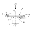
- FIG. 2 is a side view showing a configuration example of the laser beam generating apparatus.
- the laser beam generating apparatus 2 includes, for example, a laser diode 21, a collimating lens 22, a mirror 23, a polygon mirror driving motor 24, and a polygon mirror 25.
- the laser diode 21 is a laser source (laser diode) that emits a laser beam L0 in accordance with a control signal output from the control device 1.
- the infrared laser beam L0 is intermittently output in response to a pulse signal output from the control device 1. Radiate.
- the collimating lens 22 is an optical element that converts the laser beam L0 emitted from the laser diode 21 into a parallel laser beam L1.
- the mirror 23 is an optical element for reflecting the parallel laser beam L1 from the collimating lens 22 and guiding it to the polygon mirror 25.
- the polygon mirror driving motor 24 is an electric motor for rotationally driving the polygon mirror 25 in accordance with a control signal output from the control device 1, and for example, rotates the polygon mirror 25 at a constant rotational speed.
- the polygon mirror 25 is a rotating body that is rotated by the polygon mirror driving motor 24 and has a plurality of reflecting surfaces formed on the outer peripheral surface.
- the polygon mirror 25 receives the parallel laser beam L1 reflected by the mirror 23 at each of a plurality of reflecting surfaces, reflects the parallel laser beam L1 again, and generates a measurement laser beam L2 irradiated in a predetermined direction. To do.
- Each of the plurality of reflecting surfaces has a divergence angle of the measurement laser beam L2 irradiated in a predetermined direction (particularly, a divergence angle in a plane including the rotation axis 25a of the polygon mirror 25 and the optical axis of the measurement laser beam L2).
- the shape is determined so that a desired angle is obtained.
- the polygon mirror 25 has a regular hexagonal top surface 25b (see FIG. 4) when viewed from the direction of the rotation axis 25a (the direction of the arrow AR1), and has a width of 60 degrees in the circumferential direction.
- Six reflective surfaces R1 to R6 are provided.
- the polygon mirror 25 may include a number of reflection surfaces other than six on the outer periphery, and the circumferential widths (angles) of the plurality of reflection surfaces may be different from one another.
- the light receiving device 3 is a device for receiving the reflected light of the measurement laser beam emitted from the laser beam generating device 2 in a predetermined direction. For example, a photodiode that receives the reflected light and converts it into an electrical signal is provided. Adopted.
- FIGS. 3 is a side view of the polygon mirror 25.
- the measurement laser beams L21 to L26 generated when the parallel laser beam L1 from the mirror 23 is reflected by each of the six reflecting surfaces R1 to R6 are shown.
- Show. 4 is a view of the polygon mirror 25 as viewed from the direction of the arrow AR1 in FIG. 2
- FIG. 5 is a view showing the front in the vehicle traveling direction when the measurement laser beam L2 is irradiated.
- the reflecting surface R1 reflects the parallel laser beam L1 from the mirror 23 toward the front in the vehicle traveling direction, and generates a laser beam L21 for measuring the spread angle ⁇ .
- the measurement laser beam L21 has an optical axis that extends in a direction inclined by an angle 2 ⁇ upward with respect to a reference line (for example, a horizontal line) HL extending perpendicularly to the rotation axis 25a.
- a reference line for example, a horizontal line
- the reflection surface R1 may be formed to include a convex curved surface so as to generate a desired spread angle ⁇ , or may be formed to include a plurality of planes having different angles with respect to the rotation axis 25. Good. The same applies to the reflecting surfaces R2 to R6.
- the laser beam generating apparatus 2 starts from the laser diode 21 so that the parallel laser beam L1 scans the reflection surface R1 of the polygon mirror 25 rotating at a predetermined speed over the width W1.
- the infrared laser beam L0 is intermittently emitted for a predetermined time.
- the measurement laser beam L21 corresponds to the width W1 while moving the optical axis direction from the road surface RS at a predetermined height from the left to the right as the polygon mirror 25 rotates.
- the region L210 in front of the traveling direction is irradiated as many times as the number of irradiations (four in this embodiment) (that is, each of the four small regions L211 to L214 is irradiated).
- the reflection surface R2 reflects the parallel laser beam L1 forward in the vehicle traveling direction, and generates a measurement laser beam L22 having a spread angle ⁇ .
- the measurement laser beam L22 has an optical axis that extends in a direction inclined upward by an angle ⁇ with respect to the reference line HL.
- the laser beam generator 2 causes the parallel laser beam L1 to traverse the reflecting surface R2 across the width W1.
- the measurement laser beam L22 irradiates a region adjacent to the front side in the traveling direction below the region irradiated with the measurement laser beam L21 by four irradiations corresponding to the width W1.
- the reflecting surface R3 reflects the parallel laser beam L1 forward in the vehicle traveling direction, and generates a measurement laser beam L23 having a spread angle ⁇ .
- the measurement laser beam L23 has an optical axis directed in the direction of the reference line HL.
- the laser beam generator 2 causes the parallel laser beam L1 to traverse the reflecting surface R3 over the width W1.
- the measurement laser beam L23 irradiates a region adjacent to the front side in the traveling direction below the region irradiated with the measurement laser beam L22 by four irradiations corresponding to the width W1.
- the reflecting surface R4 reflects the parallel laser beam L1 toward the front in the vehicle traveling direction, and generates a measurement laser beam L24 having a spread angle ⁇ .
- the measurement laser beam L24 has an optical axis that extends in a direction inclined downward by an angle ⁇ with respect to the reference line HL.
- the laser beam generator 2 causes the parallel laser beam L1 to traverse the reflecting surface R4 over the width W1.
- the measurement laser beam L24 irradiates a region adjacent to the front side in the traveling direction below the region irradiated with the measurement laser beam L23 by four irradiations corresponding to the width W1.
- the reflecting surface R5 reflects the parallel laser beam L1 toward the road surface, and generates a measurement laser beam L25 having a spread angle ⁇ ( ⁇ > ⁇ ).
- the measurement laser beam L25 has an optical axis that extends in a direction inclined downward by an angle ⁇ ( ⁇ > ⁇ ) with respect to the reference line HL.
- the laser beam generating apparatus 2 causes the parallel laser beam L1 to cross across the reflection surface R5 over the width W2 (W2> W1).
- the measurement laser beam L25 irradiates the inside of the region L250 on the road surface by the number of times of irradiation corresponding to the width W2 (eight times in the present embodiment) (that is, the eight small regions L251 to L258). Irradiate each).
- the reflecting surface R6 reflects the parallel laser beam L1 toward the road surface, and generates a measurement laser beam L26 having a spread angle ⁇ .
- the measurement laser beam L26 has an optical axis that is directed downward by an angle ⁇ + ⁇ with respect to the reference line HL.
- the laser beam generator 2 causes the parallel laser beam L1 to traverse the reflecting surface R2 across the width W2.
- the measurement laser beam L26 irradiates the area adjacent to the area irradiated with the measurement laser beam L25 on the road surface by eight irradiations corresponding to the width W2.
- the reflection surfaces R1 to R4 of the polygon mirror 25 constitute a first laser irradiation unit that generates a measurement laser beam irradiated forward in the traveling direction, and the reflection of the polygon mirror 25 is performed.
- the surfaces R5 and R6 constitute a second laser irradiation unit that generates a measurement laser beam irradiated toward the road surface.
- the measurement laser beams L21 to L24 are used to measure the position of an object ahead in the traveling direction, and the measurement laser beams L25 and L26 measure the position of the road marking on the road surface. Used for.
- one scanning from the left to the right by each of the measurement laser beams L21 to L24 includes four irradiations, and each scanning proceeds from vertically upward to downward. I am going to do it.
- one scan from the left to the right by each of the measurement laser beams L25 and L26 includes eight irradiations, and the scan by the measurement laser beam L26 is in front of the scan by the measurement laser beam L25 (on the vehicle). It is supposed to be in the nearer one.
- each scanning of the measurement laser beam L2 actually includes a larger number of irradiations, and the number of irradiations can be set individually.
- the order of scanning in the forward direction may proceed from vertically downward to vertically upward, and is random regardless of the traveling direction. It may be anything.
- the order of scanning on the road surface may proceed in a direction away from the vehicle, and is random regardless of the traveling direction. There may be.
- scanning with each of the measurement laser beams L21 to L26 proceeds from left to right, but may proceed from right to left, and may be performed in the vertical direction (from above). It may progress from the bottom or from the bottom to the top), or may proceed in an oblique direction.
- the measurement laser beam scans the front in the traveling direction four times and scans the road surface twice in a series of irradiation processes, but scans the front in the traveling direction and the road surface three times each. Other combinations of the number of scans may be employed.
- the laser beam generator 2 generates the measurement laser beam so that the irradiation regions do not overlap each other, but the irradiation regions partially overlap or between the irradiation regions.
- the measurement laser beam may be generated so as to have a predetermined interval.
- control device 1 various functional elements of the control device 1 will be described.
- the drive control unit 10 is a functional element for controlling the drive of the laser beam generation device 2. For example, the drive control unit 10 outputs a control signal to the laser diode 21 and the polygon mirror drive motor 24 to control the laser beam generation device 2. Drive in a desired state.
- the drive control unit 10 appropriately synchronizes the emission timing of the laser beam L0 by the laser diode 21 and the rotational speed of the polygon mirror 25 by the polygon mirror driving motor 24.
- the road marking detection unit 11 is a functional element for detecting a road marking on the road surface. For example, based on the output of the light receiving device 3, the intensity of the reflected light, between the laser beam generating device 2 and the reflection point The road marking is detected by deriving the distance, the existence direction of the reflection point as seen from the laser beam generator 2, and the like.
- the road marking detection unit 11 detects the road marking on the road surface by receiving the reflected light of the measurement laser beam irradiated toward the road surface with the light receiving device 3.
- the “road marking” is a sign existing on the road surface, for example, a lane boundary line (for example, a continuous line or a broken line) painted on the road surface, a road fence (for example, botsdots or cats) embedded in the road surface. Eye.) Etc.
- the “reflection point” is a point corresponding to a position where each of the measurement laser beams L2 reflects, for example, a point on each optical axis of the measurement laser beam L2 directed toward the road surface.
- the road marking detection unit 11 determines whether the laser beam generating device 2 and the reflection point are based on the time from the emission time of the laser beam L0 by the laser diode 21 to the light reception time by the light receiving device 3 and the speed of light. The distance between them (hereinafter referred to as “reflection point distance”) is calculated.
- the road marking detection unit 11 derives the irradiation direction of the measurement laser beam L2 and the existence direction of the reflection point based on the emission time and the driving state of the laser beam generating device 2 (the rotation state of the polygon mirror 25). .
- the road sign detection unit 11 reflects the reflected light if the intensity of the reflected light is equal to or greater than a predetermined value and the height of the reflection point calculated based on the reflection point distance is substantially the same as the road surface.
- the points are extracted as reflection points on the road marking (hereinafter referred to as “effective reflection points”).
- the road sign detection unit 11 is a coordinate value of an effective reflection point in a two-dimensional orthogonal coordinate system in which the position of the laser beam generating device 2 is the origin, the distance in the vehicle width direction is the X axis, and the distance in the vehicle traveling direction is the Y axis. Is calculated.
- the road marking detection unit 11 repeats the above-described processing to extract a plurality of effective reflection points, calculates the coordinate values of each of these effective reflection points, and determines the position of the lane boundary line.
- the road sign detection unit 11 makes the detection of the position of the lane boundary line at the present time efficient based on the movement amount of the own vehicle in the unit time and the position of the road boundary line determined before the unit time. .
- the road marking detection unit 11 estimates the amount of movement of the host vehicle in unit time based on the output of a vehicle speed sensor, a steering angle sensor (both not shown), and the like, and based on the estimated amount of movement. Thus, the position of the road boundary determined before unit time is moved to the current position on the coordinate system.
- the road sign detection unit 11 selects only the reflection point group existing near the road boundary after the movement from the current reflection point group, and reduces the load related to the extraction process of the effective reflection point group. Like that.
- the parameter a 0 is a deviation [meter] in the vehicle width direction of the host vehicle with respect to the lane center line
- the parameter a 1 is an angle [radian] of the vehicle traveling direction with respect to the lane direction
- the parameter a 2 is a lane.
- the curvature is 1 / meter.
- the object detection unit 12 is a functional element for detecting an object existing ahead in the vehicle traveling direction. For example, the intensity of the reflected light is based on the output of the light receiving device 3 as in the processing by the road sign detection unit 11. Then, the object is detected by deriving the distance between the laser beam generating device 2 and the reflection point, the existence direction of the reflection point viewed from the laser beam generating device 2, and the like.
- the object detection unit 12 detects an object present in the vehicle traveling direction by receiving the reflected light of the measurement laser beam emitted toward the front in the traveling direction by the light receiving device 3.
- FIGS. 7 and 8 each show a combined view of a view of a vehicle that irradiates a measurement laser beam as seen from the side and a view as seen from above.
- the measurement laser beams L25 and L26 having a spread angle ⁇ ( ⁇ > ⁇ ) larger than the spread angle ⁇ of the measurement laser beams L21 to L24 irradiated forward in the traveling direction are irradiated toward the road surface. Irradiation areas L250 and L260 at the time of being performed are shown. Note that the measurement laser beams L21 to L26 in FIG. 7 correspond to the measurement laser beams L21 to L26 in FIG. 3 and have angles + 2 ⁇ , + ⁇ , ⁇ 0, and ⁇ with respect to the horizontal line HL that is a reference line, respectively. , ⁇ , and ⁇ ( ⁇ + ⁇ ).
- FIG. 8 shows a case where the measurement laser beams L25C and L26C having the same spread angle ⁇ as the measurement laser beams L21 to L24 irradiated forward in the traveling direction are irradiated toward the road surface. Irradiation areas L250C and L260C are shown.
- the measurement laser beams L25C and L26C in FIG. 8 have optical axes inclined downward by angles 3 ⁇ and 4 ⁇ , respectively, with respect to the horizontal line HL that is a reference line, and are smaller than the irradiation regions L250 and L260 in FIG. L250C and L260C are formed on the road surface.
- the laser beam generator 2 may generate a situation in which the botsdots BD cannot be included in any of the irradiation regions L250C and L260C.
- the measurement laser beams L25 and L26 in FIG. 7 have optical axes inclined downward by angles ⁇ and ⁇ + ⁇ respectively with respect to the horizontal line HL as a reference line (see FIG. 3), and the irradiation region of FIG. Irradiation areas L250 and L260 larger than L250C and L260C are formed on the road surface.
- the laser beam generator 2 can more reliably include the botsdots BD in the irradiation regions L250 and L260.
- the laser radar device 100 irradiates the road surface with the measurement laser beams L25 and L26 having the spread angle ⁇ larger than the spread angle ⁇ of the measurement laser beams L21 to L24 irradiated forward in the traveling direction.
- the road marking (Botts Dots BD) to be detected can be more reliably included in the irradiation area, and the detection rate of the road marking (Botts Dots BD) can be improved.
- the detection rate of road marking means the probability that the road marking is included in the irradiation area.
- the laser radar device 100 makes the divergence angles of the measurement laser beams L25 and L26 irradiated toward the road surface larger than the divergence angles ⁇ of the measurement laser beams L21 to L24 irradiated toward the front in the traveling direction. Thereby, the laser radar device 100 can reduce the number of times of irradiation per unit time on the road surface without reducing the irradiation area on the road surface and without reducing the detection rate of the road marking. As a result, when the number of irradiations per unit time is limited, the laser radar device 100 can allocate a larger number of irradiations to the measurement laser beam irradiated forward in the traveling direction. This also leads to a reduction in the divergence angle of the measurement laser beam irradiated toward the front in the traveling direction, and the laser radar apparatus 100 can improve the detection performance (resolution) of an object existing in the forward direction. it can.
- FIG. 9 is a composite view of a vehicle viewed from the side and a diagram viewed from above, as in FIGS. 7 and 8.
- FIG. 9 it is assumed that a broken line boundary line PM is painted on the road surface instead of the botsdots BD in FIGS.
- the laser beam generating apparatus 2 sets the number of scanning of the measurement laser beam to be irradiated toward the front in the traveling direction and the road surface to three in front of the traveling direction.
- the measurement laser beams L21, L22, and L23 are irradiated toward the surface, and the measurement laser beams L24N, L25N, and L26N are irradiated toward the road surface.
- the divergence angles of the measurement laser beams L24N, L25N, and L26N irradiated toward the road surface are larger than the divergence angles ⁇ of the measurement laser beams L21, L22, and L23 irradiated toward the front in the traveling direction. Is set.
- the divergence angles of the measurement laser beams L24N, L25N, and L26N are set so that the lengths of the irradiation areas L240N, L250N, and L260N on the road surface are substantially the same length D1.
- the divergence angle of the measurement laser beam L26N is the largest, and the divergence angles become smaller in the order of L25N and L24N.
- the length D1 is set to, for example, 5 meters or more which is the length of each broken line boundary line PM and also the length between the two broken line boundary lines PM.
- the divergence angles of the measurement laser beams L24N, L25N, and L26N are set to 2 degrees, 5 degrees, and 15 degrees, for example.
- the laser radar device 100 irradiates the measurement laser beams L24N to L26N having an divergence angle larger than the divergence angle ⁇ of the measurement laser beams L21 to L23 radiated forward in the traveling direction toward the road surface.
- the road sign (broken line boundary line PM) that appears intermittently can be included in the irradiation region more reliably, and the detection rate of the road sign (broken line boundary line PM) that appears intermittently can be improved.
- the laser radar device 100 makes the divergence angle of the measurement laser beams L24N to L26N irradiated toward the road surface larger than the divergence angle ⁇ of the measurement laser beams L21 to L23 irradiated toward the front in the traveling direction. Thereby, the laser radar device 100 can reduce the number of times of irradiation per unit time on the road surface without reducing the irradiation area on the road surface and without reducing the detection rate of the road marking. As a result, when the number of irradiations per unit time is limited, the laser radar device 100 can allocate a larger number of irradiations to the measurement laser beam irradiated forward in the traveling direction. This also leads to a reduction in the divergence angle of the measurement laser beam irradiated toward the front in the traveling direction, and the laser radar apparatus 100 can improve the detection performance (resolution) of an object existing in the forward direction. it can.
- the laser radar device 100 is configured so that the irradiation direction lengths of the irradiation regions L240N to L260N by the measurement laser beams L24N to L26N irradiated toward the road surface are equal to or greater than the interval of the road marking that appears intermittently. Irradiate laser beams for measurement L24N to L26N. Thereby, the laser radar device 100 can include road signs that appear intermittently in each of the irradiation regions L240N to L260N, and can improve the detection rate of road signs that appear intermittently.
- the laser beam generating apparatus 2A is different from the laser beam generating apparatus 2 of FIG. 2 in that it includes two polygon mirrors 25H and 25L that can be switched and a linear motor 26 for switching between them. In common.
- the laser radar device 100 reflects the parallel laser beam L1 reflected by the mirror 23 on each of the reflection surfaces of the polygon mirror 25L to generate a measurement laser beam L2.
- the divergence angle of the measurement laser beam irradiated toward the road surface becomes equal to the divergence angle of the measurement laser beam irradiated toward the front in the traveling direction.
- the number of scanning laser beams for measurement irradiated toward the road surface is three.
- control device 1 of the laser radar device 100 gives the laser beam generation device 2A a response when a switching command is input from the operator or when the road marking detection rate falls below a predetermined level. Output a control signal.
- the laser beam generator 2A moves the polygon mirror driving motor 24, the polygon mirror 25H, and the polygon mirror 25L in the direction of the arrow AR2 by the linear motor 26 in accordance with a control signal from the controller 1.
- the laser beam generating apparatus 2A generates the measurement laser beam L2A so that the parallel laser beam L1 hits the reflecting surface of the polygon mirror 25H instead of the reflecting surface of the polygon mirror 25L.
- Each of the reflection surfaces of the polygon mirror 25H has a divergence angle of the measurement laser beam emitted toward the road surface larger than the divergence angle of the measurement laser beam emitted toward the front in the advancing direction.
- the number of scans of the measurement laser beam irradiated toward the front (for example, four) is larger than the number of scans of the measurement laser beam irradiated toward the road surface (for example, two).
- the laser radar apparatus 100 reduces the divergence angle of the measurement laser beam emitted toward the road surface to reduce the power density in the irradiation area.
- the detection sensitivity of road marking can be improved.
- the laser radar device 100 increases the irradiation area by relatively widening the divergence angle of the measurement laser beam irradiated toward the road surface, and The detection rate can be improved.
- the laser radar apparatus 100 detects an object existing forward in the traveling direction by allocating a larger number of irradiations to the measurement laser beam irradiated toward the front in the traveling direction and relatively reducing the divergence angle. Performance (resolution) can be improved.
- the laser beam generating apparatus 2A may include an actuator that switches the tilt angle of the mirror 23 instead of the linear motor 26, and the tilt angle of the mirror 23 may be switched according to a control signal from the control device 1. .
- the laser beam generating apparatus 2A can switch the reflecting surface of the parallel laser beam L1 between the polygon mirror 25L and the polygon mirror 25H, and realize the same effect as when the linear motor 26 is used. Can do.
- the plurality of reflecting surfaces of the polygon mirror are formed so that the respective widths (circumferential angles) are equal, but a desired scanning width of the measurement laser beam can be realized.
- Each may have a different width.
- the laser beam generation apparatus does not need to interrupt the generation of the measurement laser beam (laser beam emission by the laser diode) at the switching of the reflection surface, and simplifies the processing related to the generation of the measurement laser beam. Can do.
Landscapes
- Physics & Mathematics (AREA)
- Engineering & Computer Science (AREA)
- General Physics & Mathematics (AREA)
- Computer Networks & Wireless Communication (AREA)
- Radar, Positioning & Navigation (AREA)
- Remote Sensing (AREA)
- Optics & Photonics (AREA)
- Electromagnetism (AREA)
- Optical Radar Systems And Details Thereof (AREA)
Abstract
Description
2、2A レーザビーム生成装置
3 受光装置
10 駆動制御部
11 道路標示検出部
12 物体検出部
21 レーザダイオード
22 コリメートレンズ
23 ミラー
24 ポリゴンミラー駆動用モータ
25、25H、25L ポリゴンミラー
25a ポリゴンミラーの回転軸
25b ポリゴンミラーの頂面
26 リニアモータ
100 レーザレーダ装置
L0 レーザダイオードが放射するレーザビーム
L1 コリメートレンズが生成する平行レーザビーム
L2、L2A 測定用レーザビーム
L21~L26 測定用レーザビーム
L25C、L26C 測定用レーザビーム
L24N~L26N 測定用レーザビーム
L210~L260 一回の走査による照射領域
L250C、L260C 一回の走査による照射領域
L240N~L260N 一回の走査による照射領域
L211~L214、L251~L258 一回の照射による照射領域
R1~R6 反射面
RS 路面
Claims (4)
- 車両に搭載されレーザレーダ装置であって、
レーザ源が放射するレーザビームを用いて測定用レーザビームを生成し、進行方向前方の所定範囲を照射する第一レーザ照射部と、
前記レーザ源が放射するレーザビームを用いて測定用レーザビームを生成し、路面上の所定範囲を照射する第二レーザ照射部と、を備え、
前記第二レーザ照射部が生成する測定用レーザビームの車両側方から見たビーム拡がり角は、前記第一レーザ照射部が生成する測定用レーザビームの車両側方から見たビーム拡がり角よりも大きい、
ことを特徴とするレーザレーダ装置。 - 前記第二レーザ照射部は、少なくとも一回の走査で路面上の所定範囲を照射し、
前記第二レーザ照射部が生成する測定用レーザビームの車両側方から見たビーム拡がり角は、二回以上の走査で前記路面上の所定範囲が照射される場合、各走査における測定用レーザビームによる路面上の照射領域の長さを略一定にする角度であり、
該照射領域の長さは、所定間隔で繰り返される道路標示の該所定間隔以上の長さに設定される、
ことを特徴とする請求項1に記載のレーザレーダ装置。 - 前記第一レーザ照射部及び前記第二レーザ照射部はそれぞれ、回転するポリゴンミラーにおける複数の反射面のそれぞれで前記レーザ源が放射するレーザビームを反射させて測定用レーザビームを生成し、
前記第二レーザ照射部は、凸面状の反射面で前記レーザ源が放射するレーザビームを反射させて測定用レーザビームを生成する、
ことを特徴とする請求項1に記載のレーザレーダ装置。 - 前記第一レーザ照射部は、進行方向前方の車両又は障害物の位置を測定する測定用レーザビームを生成し、
前記第二レーザ照射部は、路面上の道路標示の位置を測定する測定用レーザビームを生成する、
ことを特徴とする請求項1に記載のレーザレーダ装置。
Priority Applications (5)
| Application Number | Priority Date | Filing Date | Title |
|---|---|---|---|
| PCT/JP2011/054797 WO2012117542A1 (ja) | 2011-03-02 | 2011-03-02 | レーザレーダ装置 |
| CN201180068683.9A CN103403577B (zh) | 2011-03-02 | 2011-03-02 | 激光雷达装置 |
| EP11859968.7A EP2682784B1 (en) | 2011-03-02 | 2011-03-02 | Laser radar device |
| US14/002,023 US8994928B2 (en) | 2011-03-02 | 2011-03-02 | Laser radar device |
| JP2013502107A JP5541410B2 (ja) | 2011-03-02 | 2011-03-02 | レーザレーダ装置 |
Applications Claiming Priority (1)
| Application Number | Priority Date | Filing Date | Title |
|---|---|---|---|
| PCT/JP2011/054797 WO2012117542A1 (ja) | 2011-03-02 | 2011-03-02 | レーザレーダ装置 |
Publications (1)
| Publication Number | Publication Date |
|---|---|
| WO2012117542A1 true WO2012117542A1 (ja) | 2012-09-07 |
Family
ID=46757502
Family Applications (1)
| Application Number | Title | Priority Date | Filing Date |
|---|---|---|---|
| PCT/JP2011/054797 Ceased WO2012117542A1 (ja) | 2011-03-02 | 2011-03-02 | レーザレーダ装置 |
Country Status (5)
| Country | Link |
|---|---|
| US (1) | US8994928B2 (ja) |
| EP (1) | EP2682784B1 (ja) |
| JP (1) | JP5541410B2 (ja) |
| CN (1) | CN103403577B (ja) |
| WO (1) | WO2012117542A1 (ja) |
Cited By (22)
| Publication number | Priority date | Publication date | Assignee | Title |
|---|---|---|---|---|
| JP2014071027A (ja) * | 2012-09-28 | 2014-04-21 | Denso Wave Inc | レーザレーダ装置 |
| JP2014228637A (ja) * | 2013-05-21 | 2014-12-08 | 株式会社デンソー | 道路情報送信装置、地図生成装置、道路情報収集システム |
| JP2015007578A (ja) * | 2013-06-25 | 2015-01-15 | 株式会社デンソー | 光走査装置 |
| US20150092184A1 (en) * | 2013-03-12 | 2015-04-02 | Pictometry International Corp. | Lidar System Producing Multiple Scan Paths and Method of Making and Using Same |
| JP2015152574A (ja) * | 2014-02-19 | 2015-08-24 | 株式会社豊田中央研究所 | 物体検出装置及び距離測定装置 |
| JP2017150902A (ja) * | 2016-02-23 | 2017-08-31 | 株式会社Ihiエアロスペース | 車載レーザレーダ装置 |
| JP2018059847A (ja) * | 2016-10-06 | 2018-04-12 | オムロンオートモーティブエレクトロニクス株式会社 | レーザレーダ装置 |
| US9969325B2 (en) | 2015-09-15 | 2018-05-15 | International Business Machines Corporation | Projected surface markings |
| JP2020509412A (ja) * | 2017-02-28 | 2020-03-26 | ヴァレオ・シャルター・ウント・ゼンゾーレン・ゲーエムベーハー | 光学取得装置の発光ユニット用の光学素子、発光ユニット、光学取得装置、自動車両、及び方法 |
| JP2020511639A (ja) * | 2017-03-17 | 2020-04-16 | ウェイモ エルエルシー | 乗物センサの可変ビーム間隔、タイミング、およびパワー |
| WO2020170700A1 (ja) * | 2019-02-20 | 2020-08-27 | 株式会社デンソー | 車両周辺監視システム |
| JP2020134516A (ja) * | 2019-02-20 | 2020-08-31 | 株式会社デンソー | 車両周辺監視システム |
| JP2020190568A (ja) * | 2016-04-28 | 2020-11-26 | 株式会社ユピテル | 出射装置 |
| JP2021001787A (ja) * | 2019-06-21 | 2021-01-07 | 三菱電機株式会社 | レーザ距離測定装置 |
| JP2021127075A (ja) * | 2020-02-17 | 2021-09-02 | 株式会社デンソー | 道路勾配推定装置、道路勾配推定システムおよび道路勾配推定方法 |
| WO2021199606A1 (ja) | 2020-03-31 | 2021-10-07 | パイオニア株式会社 | 情報処理装置 |
| JP2021533381A (ja) * | 2018-10-02 | 2021-12-02 | ブラックモア センサーズ アンド アナリティクス エルエルシー | コヒーレントlidarのスキャニングを最適化するための方法およびシステム |
| JP2021193388A (ja) * | 2020-08-11 | 2021-12-23 | 株式会社ユピテル | 出射装置 |
| JP2022052270A (ja) * | 2020-09-23 | 2022-04-04 | 株式会社デンソー | Lidar装置 |
| JP2023525392A (ja) * | 2020-06-19 | 2023-06-15 | オーロラ・オペレイションズ・インコーポレイティッド | Lidarシステム |
| JP2024035511A (ja) * | 2022-09-02 | 2024-03-14 | 本田技研工業株式会社 | 外界認識装置 |
| JP2024035512A (ja) * | 2022-09-02 | 2024-03-14 | 本田技研工業株式会社 | 区画線認識装置 |
Families Citing this family (90)
| Publication number | Priority date | Publication date | Assignee | Title |
|---|---|---|---|---|
| US11609336B1 (en) | 2018-08-21 | 2023-03-21 | Innovusion, Inc. | Refraction compensation for use in LiDAR systems |
| US20140292557A1 (en) * | 2013-04-02 | 2014-10-02 | Joseph E. Ajala | Vehicle Collision Detection And Barrier Deployment System |
| US10078136B2 (en) | 2014-03-25 | 2018-09-18 | Amazon Technologies, Inc. | Sense and avoid for automated mobile vehicles |
| US9656805B1 (en) | 2014-12-12 | 2017-05-23 | Amazon Technologies, Inc. | Mobile base utilizing transportation units for receiving items |
| US9928474B1 (en) | 2014-12-12 | 2018-03-27 | Amazon Technologies, Inc. | Mobile base utilizing transportation units for delivering items |
| US9453941B2 (en) * | 2014-12-22 | 2016-09-27 | GM Global Technology Operations LLC | Road surface reflectivity detection by lidar sensor |
| JP6453701B2 (ja) * | 2015-04-23 | 2019-01-16 | 株式会社デンソー | 姿勢推定装置 |
| CN106324618B (zh) * | 2015-06-17 | 2019-03-15 | 高田汽车电子(上海)有限公司 | 实现基于激光雷达检测车道线系统的方法 |
| US10832426B2 (en) | 2015-09-24 | 2020-11-10 | Apple Inc. | Systems and methods for surface monitoring |
| WO2017053407A1 (en) | 2015-09-24 | 2017-03-30 | Quovard Management Llc | Systems and methods for localization using surface imaging |
| CN105353377B (zh) * | 2015-09-30 | 2018-01-30 | 上海斐讯数据通信技术有限公司 | 一种机动车倒车雷达监测装置 |
| KR102368666B1 (ko) * | 2016-03-09 | 2022-03-03 | 한국전자통신연구원 | 전자 장치 및 그 제어 방법 |
| JP6765039B2 (ja) * | 2016-04-28 | 2020-10-07 | 株式会社ユピテル | 出射装置 |
| US10442439B1 (en) | 2016-08-18 | 2019-10-15 | Apple Inc. | System and method for road friction coefficient estimation |
| CN106546996A (zh) * | 2016-10-15 | 2017-03-29 | 北海益生源农贸有限责任公司 | 基于四线激光雷达的道路检测与跟踪方法 |
| US11300683B2 (en) | 2016-12-30 | 2022-04-12 | Innovusion Ireland Limited | Multiwavelength LiDAR design |
| US10942257B2 (en) | 2016-12-31 | 2021-03-09 | Innovusion Ireland Limited | 2D scanning high precision LiDAR using combination of rotating concave mirror and beam steering devices |
| US11009605B2 (en) | 2017-01-05 | 2021-05-18 | Innovusion Ireland Limited | MEMS beam steering and fisheye receiving lens for LiDAR system |
| US11054508B2 (en) | 2017-01-05 | 2021-07-06 | Innovusion Ireland Limited | High resolution LiDAR using high frequency pulse firing |
| US10969475B2 (en) | 2017-01-05 | 2021-04-06 | Innovusion Ireland Limited | Method and system for encoding and decoding LiDAR |
| WO2018137131A1 (en) | 2017-01-24 | 2018-08-02 | SZ DJI Technology Co., Ltd. | Flight indication apparatuses, systems and associated methods |
| WO2018176275A1 (en) * | 2017-03-29 | 2018-10-04 | SZ DJI Technology Co., Ltd. | System and method for supporting lidar applications |
| CN110383647B (zh) | 2017-03-29 | 2022-10-25 | 深圳市大疆创新科技有限公司 | 中空马达设备及相关系统和方法 |
| CN110199204A (zh) * | 2017-03-29 | 2019-09-03 | 深圳市大疆创新科技有限公司 | 具有小形状因子的激光雷达传感器系统 |
| EP3602121A4 (en) | 2017-03-29 | 2021-05-12 | SZ DJI Technology Co., Ltd. | CIRCUIT FOR PROCESSING LIGHT DETECTION AND DISTANCE MEASUREMENT (LIDAR) SIGNALS |
| CN110573901A (zh) | 2017-04-28 | 2019-12-13 | 深圳市大疆创新科技有限公司 | 激光传感器和视觉传感器的校准 |
| EP3616159A4 (en) | 2017-04-28 | 2020-05-13 | SZ DJI Technology Co., Ltd. | CALIBRATION OF LASER SENSORS |
| EP3615979A4 (en) | 2017-04-28 | 2020-03-25 | SZ DJI Technology Co., Ltd. | ANGLE CALIBRATION IN A LIGHT DETECTION AND DISTANCE MEASURING SYSTEM |
| EP3455645A4 (en) | 2017-07-20 | 2019-04-24 | SZ DJI Technology Co., Ltd. | SYSTEMS AND METHOD FOR OPTICAL SPACING MEASUREMENT |
| CN110914703A (zh) | 2017-07-31 | 2020-03-24 | 深圳市大疆创新科技有限公司 | 对点云中基于运动的不准确性的校正 |
| CN111033312A (zh) | 2017-08-31 | 2020-04-17 | 深圳市大疆创新科技有限公司 | 光学距离测量设备的延迟时间校准及相关联的系统和方法 |
| WO2019079642A1 (en) | 2017-10-19 | 2019-04-25 | Innovusion Ireland Limited | LIDAR WITH EXTENDED DYNAMIC RANGE |
| WO2019099096A1 (en) * | 2017-11-16 | 2019-05-23 | MultiSensor Scientific, Inc. | Systems and methods for multispectral imaging and gas detection using a scanning illuminator and optical sensor |
| US11493601B2 (en) | 2017-12-22 | 2022-11-08 | Innovusion, Inc. | High density LIDAR scanning |
| WO2019135494A1 (ko) | 2018-01-08 | 2019-07-11 | 주식회사 에스오에스랩 | 라이다 장치 |
| US10591598B2 (en) * | 2018-01-08 | 2020-03-17 | SOS Lab co., Ltd | Lidar device |
| WO2019139895A1 (en) * | 2018-01-09 | 2019-07-18 | Innovusion Ireland Limited | Lidar detection systems and methods that use multi-plane mirrors |
| US11675050B2 (en) | 2018-01-09 | 2023-06-13 | Innovusion, Inc. | LiDAR detection systems and methods |
| US11927696B2 (en) | 2018-02-21 | 2024-03-12 | Innovusion, Inc. | LiDAR systems with fiber optic coupling |
| WO2019165130A1 (en) | 2018-02-21 | 2019-08-29 | Innovusion Ireland Limited | Lidar detection systems and methods with high repetition rate to observe far objects |
| WO2019165289A1 (en) | 2018-02-22 | 2019-08-29 | Innovusion Ireland Limited | Receive path for lidar system |
| WO2019165095A1 (en) | 2018-02-23 | 2019-08-29 | Innovusion Ireland Limited | Distributed lidar systems |
| CN112292608B (zh) * | 2018-02-23 | 2024-09-20 | 图达通智能美国有限公司 | 用于lidar系统的二维操纵系统 |
| WO2020013890A2 (en) | 2018-02-23 | 2020-01-16 | Innovusion Ireland Limited | Multi-wavelength pulse steering in lidar systems |
| US11567182B2 (en) | 2018-03-09 | 2023-01-31 | Innovusion, Inc. | LiDAR safety systems and methods |
| WO2019199796A1 (en) | 2018-04-09 | 2019-10-17 | Innovusion Ireland Limited | Compensation circuitry for lidar receiver systems and method of use thereof |
| US11289873B2 (en) | 2018-04-09 | 2022-03-29 | Innovusion Ireland Limited | LiDAR systems and methods for exercising precise control of a fiber laser |
| KR102050599B1 (ko) | 2018-05-14 | 2019-12-02 | 주식회사 에스오에스랩 | 라이다 장치 |
| CN112585492B (zh) | 2018-06-15 | 2024-10-25 | 图达通智能美国有限公司 | 用于聚焦感兴趣的范围的lidar系统和方法 |
| KR102664391B1 (ko) * | 2018-08-07 | 2024-05-08 | 삼성전자주식회사 | 광 스캐너 및 이를 포함하는 라이다 시스템 |
| US11579300B1 (en) | 2018-08-21 | 2023-02-14 | Innovusion, Inc. | Dual lens receive path for LiDAR system |
| US11860316B1 (en) | 2018-08-21 | 2024-01-02 | Innovusion, Inc. | Systems and method for debris and water obfuscation compensation for use in LiDAR systems |
| US11796645B1 (en) | 2018-08-24 | 2023-10-24 | Innovusion, Inc. | Systems and methods for tuning filters for use in lidar systems |
| US11614526B1 (en) | 2018-08-24 | 2023-03-28 | Innovusion, Inc. | Virtual windows for LIDAR safety systems and methods |
| US11579258B1 (en) | 2018-08-30 | 2023-02-14 | Innovusion, Inc. | Solid state pulse steering in lidar systems |
| US20200081102A1 (en) * | 2018-09-10 | 2020-03-12 | Robotic Research, Llc | Ladar for military and harsh environment use |
| CN109100704B (zh) * | 2018-09-21 | 2020-11-27 | 深圳市速腾聚创科技有限公司 | 激光雷达的光束排布方法及激光雷达系统 |
| US12313788B1 (en) | 2018-10-09 | 2025-05-27 | Seyond, Inc. | Ultrashort pulses in LiDAR systems |
| CN114114606B (zh) | 2018-11-14 | 2024-09-06 | 图达通智能美国有限公司 | 使用多面镜的lidar系统和方法 |
| US10930155B2 (en) * | 2018-12-03 | 2021-02-23 | Continental Automotive Systems, Inc. | Infrastructure sensor detection and optimization method |
| CN109404676B (zh) * | 2018-12-13 | 2021-07-27 | 百度在线网络技术(北京)有限公司 | 支撑装备及其制造方法以及控制方法、装置、设备和介质 |
| DE112020000407B4 (de) | 2019-01-10 | 2024-02-15 | Innovusion, Inc. | Lidar-systeme und -verfahren mit strahllenkung und weitwinkelsignaldetektion |
| US10976245B2 (en) | 2019-01-25 | 2021-04-13 | MultiSensor Scientific, Inc. | Systems and methods for leak monitoring via measurement of optical absorption using tailored reflector installments |
| US11486970B1 (en) | 2019-02-11 | 2022-11-01 | Innovusion, Inc. | Multiple beam generation from a single source beam for use with a LiDAR system |
| US11977185B1 (en) * | 2019-04-04 | 2024-05-07 | Seyond, Inc. | Variable angle polygon for use with a LiDAR system |
| JP2021008152A (ja) * | 2019-06-28 | 2021-01-28 | トヨタ自動車株式会社 | 車両のルーフ構造 |
| WO2021035428A1 (zh) * | 2019-08-23 | 2021-03-04 | 深圳市速腾聚创科技有限公司 | 激光雷达及自动驾驶设备 |
| KR102281886B1 (ko) | 2019-09-05 | 2021-07-26 | 주식회사 에스오에스랩 | 라이다 장치 |
| CN110531371A (zh) * | 2019-09-27 | 2019-12-03 | 无锡流深光电科技有限公司 | 一种激光雷达和激光测距方法 |
| KR102845981B1 (ko) | 2019-10-11 | 2025-08-12 | 삼성전자주식회사 | 광학 장치 및 이를 포함하는 라이다 시스템 |
| DE102019134191A1 (de) * | 2019-12-12 | 2021-06-17 | Valeo Schalter Und Sensoren Gmbh | Umlenkspiegeleinrichtung für eine optische Detektionsvorrichtung und optische Detektionsvorrichtung |
| WO2021145045A1 (ja) * | 2020-01-16 | 2021-07-22 | パナソニックIpマネジメント株式会社 | 投光装置、および移動体 |
| US12061289B2 (en) | 2021-02-16 | 2024-08-13 | Innovusion, Inc. | Attaching a glass mirror to a rotating metal motor frame |
| US11422267B1 (en) | 2021-02-18 | 2022-08-23 | Innovusion, Inc. | Dual shaft axial flux motor for optical scanners |
| JP7260575B2 (ja) * | 2021-02-25 | 2023-04-18 | 本田技研工業株式会社 | 地図生成装置 |
| EP4260086B1 (en) | 2021-03-01 | 2024-11-27 | Seyond, Inc. | Fiber-based transmitter and receiver channels of light detection and ranging systems |
| CN113119113A (zh) * | 2021-03-19 | 2021-07-16 | 深圳市优必选科技股份有限公司 | 一种避障检测装置及机器人 |
| CN115201786B (zh) * | 2021-04-09 | 2025-04-04 | 深圳引望智能技术有限公司 | 一种激光雷达的同步控制装置及方法 |
| US11555895B2 (en) | 2021-04-20 | 2023-01-17 | Innovusion, Inc. | Dynamic compensation to polygon and motor tolerance using galvo control profile |
| US11614521B2 (en) | 2021-04-21 | 2023-03-28 | Innovusion, Inc. | LiDAR scanner with pivot prism and mirror |
| US11662439B2 (en) * | 2021-04-22 | 2023-05-30 | Innovusion, Inc. | Compact LiDAR design with high resolution and ultra-wide field of view |
| WO2022225859A1 (en) | 2021-04-22 | 2022-10-27 | Innovusion, Inc. | A compact lidar design with high resolution and ultra-wide field of view |
| EP4314885A1 (en) | 2021-05-12 | 2024-02-07 | Innovusion, Inc. | Systems and apparatuses for mitigating lidar noise, vibration, and harshness |
| CN117413199A (zh) | 2021-05-21 | 2024-01-16 | 图达通智能美国有限公司 | 使用lidar扫描仪内部的检流计镜进行智能扫描的移动配置文件 |
| US11768294B2 (en) | 2021-07-09 | 2023-09-26 | Innovusion, Inc. | Compact lidar systems for vehicle contour fitting |
| US12468017B2 (en) | 2021-10-15 | 2025-11-11 | Seyond, Inc. | Integrated mirror motor galvanometer |
| CN216356147U (zh) | 2021-11-24 | 2022-04-19 | 图达通智能科技(苏州)有限公司 | 一种车载激光雷达电机、车载激光雷达及车辆 |
| US11871130B2 (en) | 2022-03-25 | 2024-01-09 | Innovusion, Inc. | Compact perception device |
| US12204033B2 (en) | 2022-03-25 | 2025-01-21 | Seyond, Inc. | Multimodal detection with integrated sensors |
| WO2023220427A1 (en) * | 2022-05-12 | 2023-11-16 | Innovusion, Inc. | Low profile lidar systems with multiple polygon scanners |
Citations (4)
| Publication number | Priority date | Publication date | Assignee | Title |
|---|---|---|---|---|
| JP2000147124A (ja) | 1998-11-12 | 2000-05-26 | Denso Corp | 車載レーダ装置 |
| JP2007178140A (ja) * | 2005-12-27 | 2007-07-12 | Hitachi Ltd | 物体検知センサ |
| JP2007310595A (ja) * | 2006-05-17 | 2007-11-29 | Denso Corp | 走行環境認識装置 |
| JP2010210324A (ja) * | 2009-03-09 | 2010-09-24 | Nissan Motor Co Ltd | 路面状況推定装置及び方法 |
Family Cites Families (4)
| Publication number | Priority date | Publication date | Assignee | Title |
|---|---|---|---|---|
| US7209221B2 (en) * | 1994-05-23 | 2007-04-24 | Automotive Technologies International, Inc. | Method for obtaining and displaying information about objects in a vehicular blind spot |
| JP3802394B2 (ja) | 2001-10-16 | 2006-07-26 | オムロン株式会社 | 車載用レーダ装置 |
| JP2010060299A (ja) | 2008-09-01 | 2010-03-18 | Omron Corp | 物体検出装置 |
| DE112008004187B4 (de) * | 2008-12-15 | 2016-06-16 | Toyota Jidosha Kabushiki Kaisha | Objektmessvorrichtung und verfahren zur verwendung in der vorrichtung |
-
2011
- 2011-03-02 EP EP11859968.7A patent/EP2682784B1/en not_active Not-in-force
- 2011-03-02 CN CN201180068683.9A patent/CN103403577B/zh not_active Expired - Fee Related
- 2011-03-02 JP JP2013502107A patent/JP5541410B2/ja active Active
- 2011-03-02 US US14/002,023 patent/US8994928B2/en active Active
- 2011-03-02 WO PCT/JP2011/054797 patent/WO2012117542A1/ja not_active Ceased
Patent Citations (4)
| Publication number | Priority date | Publication date | Assignee | Title |
|---|---|---|---|---|
| JP2000147124A (ja) | 1998-11-12 | 2000-05-26 | Denso Corp | 車載レーダ装置 |
| JP2007178140A (ja) * | 2005-12-27 | 2007-07-12 | Hitachi Ltd | 物体検知センサ |
| JP2007310595A (ja) * | 2006-05-17 | 2007-11-29 | Denso Corp | 走行環境認識装置 |
| JP2010210324A (ja) * | 2009-03-09 | 2010-09-24 | Nissan Motor Co Ltd | 路面状況推定装置及び方法 |
Non-Patent Citations (1)
| Title |
|---|
| See also references of EP2682784A4 |
Cited By (45)
| Publication number | Priority date | Publication date | Assignee | Title |
|---|---|---|---|---|
| JP2014071027A (ja) * | 2012-09-28 | 2014-04-21 | Denso Wave Inc | レーザレーダ装置 |
| US20150092184A1 (en) * | 2013-03-12 | 2015-04-02 | Pictometry International Corp. | Lidar System Producing Multiple Scan Paths and Method of Making and Using Same |
| US9244272B2 (en) * | 2013-03-12 | 2016-01-26 | Pictometry International Corp. | Lidar system producing multiple scan paths and method of making and using same |
| US11525897B2 (en) | 2013-03-12 | 2022-12-13 | Pictometry International Corp. | LiDAR system producing multiple scan paths and method of making and using same |
| US10502813B2 (en) | 2013-03-12 | 2019-12-10 | Pictometry International Corp. | LiDAR system producing multiple scan paths and method of making and using same |
| JP2014228637A (ja) * | 2013-05-21 | 2014-12-08 | 株式会社デンソー | 道路情報送信装置、地図生成装置、道路情報収集システム |
| JP2015007578A (ja) * | 2013-06-25 | 2015-01-15 | 株式会社デンソー | 光走査装置 |
| JP2015152574A (ja) * | 2014-02-19 | 2015-08-24 | 株式会社豊田中央研究所 | 物体検出装置及び距離測定装置 |
| US9969325B2 (en) | 2015-09-15 | 2018-05-15 | International Business Machines Corporation | Projected surface markings |
| JP2017150902A (ja) * | 2016-02-23 | 2017-08-31 | 株式会社Ihiエアロスペース | 車載レーザレーダ装置 |
| JP2020190568A (ja) * | 2016-04-28 | 2020-11-26 | 株式会社ユピテル | 出射装置 |
| JP2018059847A (ja) * | 2016-10-06 | 2018-04-12 | オムロンオートモーティブエレクトロニクス株式会社 | レーザレーダ装置 |
| JP2020509412A (ja) * | 2017-02-28 | 2020-03-26 | ヴァレオ・シャルター・ウント・ゼンゾーレン・ゲーエムベーハー | 光学取得装置の発光ユニット用の光学素子、発光ユニット、光学取得装置、自動車両、及び方法 |
| JP2020511639A (ja) * | 2017-03-17 | 2020-04-16 | ウェイモ エルエルシー | 乗物センサの可変ビーム間隔、タイミング、およびパワー |
| US12352895B2 (en) | 2017-03-17 | 2025-07-08 | Waymo Llc | Variable beam spacing, timing, and power for vehicle sensors |
| JP7411027B2 (ja) | 2017-03-17 | 2024-01-10 | ウェイモ エルエルシー | 乗物センサの可変ビーム間隔、タイミング、およびパワー |
| JP2022159326A (ja) * | 2017-03-17 | 2022-10-17 | ウェイモ エルエルシー | 乗物センサの可変ビーム間隔、タイミング、およびパワー |
| JP7113018B2 (ja) | 2017-03-17 | 2022-08-04 | ウェイモ エルエルシー | 乗物センサの可変ビーム間隔、タイミング、およびパワー |
| US11333746B2 (en) | 2017-03-17 | 2022-05-17 | Waymo Llc | Variable beam spacing, timing, and power for vehicle sensors |
| JP7060908B2 (ja) | 2018-10-02 | 2022-04-27 | ブラックモア センサーズ アンド アナリティクス エルエルシー | コヒーレントlidarのスキャニングを最適化するための方法およびシステム |
| JP2021533381A (ja) * | 2018-10-02 | 2021-12-02 | ブラックモア センサーズ アンド アナリティクス エルエルシー | コヒーレントlidarのスキャニングを最適化するための方法およびシステム |
| JP2022113159A (ja) * | 2018-10-02 | 2022-08-03 | ブラックモア センサーズ アンド アナリティクス エルエルシー | コヒーレントlidarのスキャニングを最適化するための方法およびシステム |
| JP7498741B2 (ja) | 2018-10-02 | 2024-06-12 | オーロラ・オペレイションズ・インコーポレイティッド | コヒーレントlidarのスキャニングを最適化するための方法およびシステム |
| US11953677B2 (en) | 2018-10-02 | 2024-04-09 | Aurora Operations Inc. | Method and system for optimizing scanning of coherent LIDAR |
| JP2020134516A (ja) * | 2019-02-20 | 2020-08-31 | 株式会社デンソー | 車両周辺監視システム |
| WO2020170700A1 (ja) * | 2019-02-20 | 2020-08-27 | 株式会社デンソー | 車両周辺監視システム |
| US20210382177A1 (en) * | 2019-02-20 | 2021-12-09 | Denso Corporation | System for monitoring surroundings of vehicle |
| JP2021001787A (ja) * | 2019-06-21 | 2021-01-07 | 三菱電機株式会社 | レーザ距離測定装置 |
| US11567178B2 (en) | 2019-06-21 | 2023-01-31 | Mitsubishi Electric Corporation | Laser distance measuring device |
| JP2021127075A (ja) * | 2020-02-17 | 2021-09-02 | 株式会社デンソー | 道路勾配推定装置、道路勾配推定システムおよび道路勾配推定方法 |
| JP7452069B2 (ja) | 2020-02-17 | 2024-03-19 | 株式会社デンソー | 道路勾配推定装置、道路勾配推定システムおよび道路勾配推定方法 |
| US12198268B2 (en) | 2020-03-31 | 2025-01-14 | Pioneer Corporation | Information processing device |
| WO2021199606A1 (ja) | 2020-03-31 | 2021-10-07 | パイオニア株式会社 | 情報処理装置 |
| JP2023525392A (ja) * | 2020-06-19 | 2023-06-15 | オーロラ・オペレイションズ・インコーポレイティッド | Lidarシステム |
| JP7353517B2 (ja) | 2020-06-19 | 2023-09-29 | オーロラ・オペレイションズ・インコーポレイティッド | Lidarシステム |
| US11977168B2 (en) | 2020-06-19 | 2024-05-07 | Aurora Operations, Inc. | LIDAR system |
| JP2021193388A (ja) * | 2020-08-11 | 2021-12-23 | 株式会社ユピテル | 出射装置 |
| JP7254380B2 (ja) | 2020-08-11 | 2023-04-10 | 株式会社ユピテル | 出射装置 |
| JP7517021B2 (ja) | 2020-09-23 | 2024-07-17 | 株式会社デンソー | Lidar装置 |
| JP2022052270A (ja) * | 2020-09-23 | 2022-04-04 | 株式会社デンソー | Lidar装置 |
| JP2024035512A (ja) * | 2022-09-02 | 2024-03-14 | 本田技研工業株式会社 | 区画線認識装置 |
| JP7486556B2 (ja) | 2022-09-02 | 2024-05-17 | 本田技研工業株式会社 | 区画線認識装置 |
| JP2024035511A (ja) * | 2022-09-02 | 2024-03-14 | 本田技研工業株式会社 | 外界認識装置 |
| JP7556922B2 (ja) | 2022-09-02 | 2024-09-26 | 本田技研工業株式会社 | 外界認識装置 |
| US12487330B2 (en) | 2022-09-02 | 2025-12-02 | Honda Motor Co., Latd. | Division line recognition apparatus |
Also Published As
| Publication number | Publication date |
|---|---|
| CN103403577A (zh) | 2013-11-20 |
| US20130342822A1 (en) | 2013-12-26 |
| EP2682784A1 (en) | 2014-01-08 |
| EP2682784A4 (en) | 2014-10-08 |
| JPWO2012117542A1 (ja) | 2014-07-07 |
| EP2682784B1 (en) | 2015-06-24 |
| JP5541410B2 (ja) | 2014-07-09 |
| CN103403577B (zh) | 2015-02-11 |
| US8994928B2 (en) | 2015-03-31 |
Similar Documents
| Publication | Publication Date | Title |
|---|---|---|
| JP5541410B2 (ja) | レーザレーダ装置 | |
| JP5267786B2 (ja) | レーザレーダ及びレーザレーダによる境界監視方法 | |
| JP5488518B2 (ja) | 道路端検出装置、運転者支援装置、および道路端検出方法 | |
| JP5267785B2 (ja) | レーザレーダ及びレーザレーダによる境界監視方法 | |
| JP5598100B2 (ja) | 物体検出装置 | |
| JP2008286565A (ja) | 物体検知装置 | |
| JP2011232325A (ja) | 物体認識装置 | |
| JP2023539790A (ja) | 光学スキャナのためのデュアルシャフト・アキシャルフラックスモータ | |
| JP2010066101A (ja) | レーザレーダ及びレーザレーダによる境界監視方法 | |
| JP5716902B2 (ja) | 監視方法及び監視装置 | |
| JP6413470B2 (ja) | 車載レーダ装置 | |
| JP5929675B2 (ja) | レーザレーダ装置 | |
| JP2008292308A (ja) | 光レーダ装置 | |
| JP2017040546A (ja) | 物体検出装置 | |
| KR20200059426A (ko) | 라이다 광학 장치 | |
| JP2007248225A (ja) | レーザビーム照射装置及び測距装置 | |
| JP6447400B2 (ja) | レーザレーダ装置及びその制御方法 | |
| JP3772700B2 (ja) | 障害物検出装置 | |
| JP2009156810A (ja) | 物体検出装置 | |
| JP5556317B2 (ja) | 物体認識装置 | |
| JP2023040167A (ja) | 走査方法の決定方法 | |
| JP6246690B2 (ja) | 移動体、計測装置及び計測方法 | |
| JP5266866B2 (ja) | 障害物検出装置 | |
| JP6569328B2 (ja) | 光走査装置、及び、車載システム | |
| US20220003843A1 (en) | Laser radar mounting structure |
Legal Events
| Date | Code | Title | Description |
|---|---|---|---|
| 121 | Ep: the epo has been informed by wipo that ep was designated in this application |
Ref document number: 11859968 Country of ref document: EP Kind code of ref document: A1 |
|
| ENP | Entry into the national phase |
Ref document number: 2013502107 Country of ref document: JP Kind code of ref document: A |
|
| WWE | Wipo information: entry into national phase |
Ref document number: 2011859968 Country of ref document: EP |
|
| WWE | Wipo information: entry into national phase |
Ref document number: 14002023 Country of ref document: US |
|
| NENP | Non-entry into the national phase |
Ref country code: DE |