US11871130B2 - Compact perception device - Google Patents
Compact perception device Download PDFInfo
- Publication number
- US11871130B2 US11871130B2 US18/105,781 US202318105781A US11871130B2 US 11871130 B2 US11871130 B2 US 11871130B2 US 202318105781 A US202318105781 A US 202318105781A US 11871130 B2 US11871130 B2 US 11871130B2
- Authority
- US
- United States
- Prior art keywords
- light
- collected
- optical reflector
- nir
- visible light
- Prior art date
- Legal status (The legal status is an assumption and is not a legal conclusion. Google has not performed a legal analysis and makes no representation as to the accuracy of the status listed.)
- Active
Links
- 230000008447 perception Effects 0.000 title claims abstract description 80
- 230000003287 optical effect Effects 0.000 claims abstract description 197
- 238000000034 method Methods 0.000 claims description 54
- 238000001514 detection method Methods 0.000 claims description 18
- 239000007787 solid Substances 0.000 claims description 6
- 238000004891 communication Methods 0.000 description 58
- 230000007246 mechanism Effects 0.000 description 37
- 239000000835 fiber Substances 0.000 description 31
- 238000012545 processing Methods 0.000 description 22
- 239000013307 optical fiber Substances 0.000 description 19
- 238000004590 computer program Methods 0.000 description 15
- 238000003860 storage Methods 0.000 description 15
- 238000010586 diagram Methods 0.000 description 12
- 230000001276 controlling effect Effects 0.000 description 10
- 230000015654 memory Effects 0.000 description 10
- 230000004927 fusion Effects 0.000 description 9
- 150000003071 polychlorinated biphenyls Chemical class 0.000 description 9
- 239000004065 semiconductor Substances 0.000 description 9
- 230000005540 biological transmission Effects 0.000 description 8
- 238000004422 calculation algorithm Methods 0.000 description 8
- 238000000576 coating method Methods 0.000 description 8
- 230000002596 correlated effect Effects 0.000 description 7
- 230000006870 function Effects 0.000 description 7
- 239000000463 material Substances 0.000 description 7
- 238000012546 transfer Methods 0.000 description 7
- 239000011248 coating agent Substances 0.000 description 6
- 230000002085 persistent effect Effects 0.000 description 6
- 230000000875 corresponding effect Effects 0.000 description 5
- 238000013461 design Methods 0.000 description 5
- 230000004807 localization Effects 0.000 description 5
- 238000012544 monitoring process Methods 0.000 description 5
- 230000008569 process Effects 0.000 description 5
- 235000004522 Pentaglottis sempervirens Nutrition 0.000 description 4
- 230000033001 locomotion Effects 0.000 description 4
- 238000005259 measurement Methods 0.000 description 4
- 230000004075 alteration Effects 0.000 description 3
- 238000013528 artificial neural network Methods 0.000 description 3
- 230000001427 coherent effect Effects 0.000 description 3
- 239000013078 crystal Substances 0.000 description 3
- 238000005516 engineering process Methods 0.000 description 3
- 238000001914 filtration Methods 0.000 description 3
- 238000007499 fusion processing Methods 0.000 description 3
- 230000003993 interaction Effects 0.000 description 3
- 238000010801 machine learning Methods 0.000 description 3
- 230000035945 sensitivity Effects 0.000 description 3
- 229910000530 Gallium indium arsenide Inorganic materials 0.000 description 2
- VYPSYNLAJGMNEJ-UHFFFAOYSA-N Silicium dioxide Chemical compound O=[Si]=O VYPSYNLAJGMNEJ-UHFFFAOYSA-N 0.000 description 2
- XUIMIQQOPSSXEZ-UHFFFAOYSA-N Silicon Chemical compound [Si] XUIMIQQOPSSXEZ-UHFFFAOYSA-N 0.000 description 2
- BQCADISMDOOEFD-UHFFFAOYSA-N Silver Chemical compound [Ag] BQCADISMDOOEFD-UHFFFAOYSA-N 0.000 description 2
- 230000001133 acceleration Effects 0.000 description 2
- 239000008186 active pharmaceutical agent Substances 0.000 description 2
- 229910052782 aluminium Inorganic materials 0.000 description 2
- XAGFODPZIPBFFR-UHFFFAOYSA-N aluminium Chemical compound [Al] XAGFODPZIPBFFR-UHFFFAOYSA-N 0.000 description 2
- 230000003321 amplification Effects 0.000 description 2
- 238000003491 array Methods 0.000 description 2
- 230000006399 behavior Effects 0.000 description 2
- 230000002457 bidirectional effect Effects 0.000 description 2
- 230000008878 coupling Effects 0.000 description 2
- 238000010168 coupling process Methods 0.000 description 2
- 238000005859 coupling reaction Methods 0.000 description 2
- 230000000694 effects Effects 0.000 description 2
- PCHJSUWPFVWCPO-UHFFFAOYSA-N gold Chemical compound [Au] PCHJSUWPFVWCPO-UHFFFAOYSA-N 0.000 description 2
- 229910052737 gold Inorganic materials 0.000 description 2
- 239000010931 gold Substances 0.000 description 2
- 230000005571 horizontal transmission Effects 0.000 description 2
- 230000036039 immunity Effects 0.000 description 2
- 238000003199 nucleic acid amplification method Methods 0.000 description 2
- 238000005457 optimization Methods 0.000 description 2
- 230000036961 partial effect Effects 0.000 description 2
- 230000009467 reduction Effects 0.000 description 2
- 230000002829 reductive effect Effects 0.000 description 2
- 239000010865 sewage Substances 0.000 description 2
- 229910052710 silicon Inorganic materials 0.000 description 2
- 239000010703 silicon Substances 0.000 description 2
- 229910052709 silver Inorganic materials 0.000 description 2
- 239000004332 silver Substances 0.000 description 2
- 230000003068 static effect Effects 0.000 description 2
- 229910019901 yttrium aluminum garnet Inorganic materials 0.000 description 2
- 229910052692 Dysprosium Inorganic materials 0.000 description 1
- 229910052691 Erbium Inorganic materials 0.000 description 1
- 229910052689 Holmium Inorganic materials 0.000 description 1
- 101100456571 Mus musculus Med12 gene Proteins 0.000 description 1
- 229910052779 Neodymium Inorganic materials 0.000 description 1
- 229910052777 Praseodymium Inorganic materials 0.000 description 1
- 229910052775 Thulium Inorganic materials 0.000 description 1
- 229910009372 YVO4 Inorganic materials 0.000 description 1
- 229910052769 Ytterbium Inorganic materials 0.000 description 1
- 230000003044 adaptive effect Effects 0.000 description 1
- JNDMLEXHDPKVFC-UHFFFAOYSA-N aluminum;oxygen(2-);yttrium(3+) Chemical compound [O-2].[O-2].[O-2].[Al+3].[Y+3] JNDMLEXHDPKVFC-UHFFFAOYSA-N 0.000 description 1
- 230000009286 beneficial effect Effects 0.000 description 1
- 230000001413 cellular effect Effects 0.000 description 1
- 239000003795 chemical substances by application Substances 0.000 description 1
- 238000005253 cladding Methods 0.000 description 1
- 238000004140 cleaning Methods 0.000 description 1
- 229910052681 coesite Inorganic materials 0.000 description 1
- 230000000295 complement effect Effects 0.000 description 1
- 238000013527 convolutional neural network Methods 0.000 description 1
- 229910052906 cristobalite Inorganic materials 0.000 description 1
- 238000013135 deep learning Methods 0.000 description 1
- 239000003814 drug Substances 0.000 description 1
- 229940079593 drug Drugs 0.000 description 1
- KBQHZAAAGSGFKK-UHFFFAOYSA-N dysprosium atom Chemical compound [Dy] KBQHZAAAGSGFKK-UHFFFAOYSA-N 0.000 description 1
- 230000005670 electromagnetic radiation Effects 0.000 description 1
- UYAHIZSMUZPPFV-UHFFFAOYSA-N erbium Chemical compound [Er] UYAHIZSMUZPPFV-UHFFFAOYSA-N 0.000 description 1
- 239000000446 fuel Substances 0.000 description 1
- 230000036541 health Effects 0.000 description 1
- KJZYNXUDTRRSPN-UHFFFAOYSA-N holmium atom Chemical compound [Ho] KJZYNXUDTRRSPN-UHFFFAOYSA-N 0.000 description 1
- 230000002452 interceptive effect Effects 0.000 description 1
- 230000000670 limiting effect Effects 0.000 description 1
- 239000004973 liquid crystal related substance Substances 0.000 description 1
- 230000007774 longterm Effects 0.000 description 1
- 238000004519 manufacturing process Methods 0.000 description 1
- 238000013507 mapping Methods 0.000 description 1
- 229910044991 metal oxide Inorganic materials 0.000 description 1
- 150000004706 metal oxides Chemical class 0.000 description 1
- 238000002044 microwave spectrum Methods 0.000 description 1
- 238000012986 modification Methods 0.000 description 1
- 230000004048 modification Effects 0.000 description 1
- QEFYFXOXNSNQGX-UHFFFAOYSA-N neodymium atom Chemical compound [Nd] QEFYFXOXNSNQGX-UHFFFAOYSA-N 0.000 description 1
- 230000010355 oscillation Effects 0.000 description 1
- 238000004806 packaging method and process Methods 0.000 description 1
- 238000003909 pattern recognition Methods 0.000 description 1
- 230000002093 peripheral effect Effects 0.000 description 1
- 238000011176 pooling Methods 0.000 description 1
- PUDIUYLPXJFUGB-UHFFFAOYSA-N praseodymium atom Chemical compound [Pr] PUDIUYLPXJFUGB-UHFFFAOYSA-N 0.000 description 1
- 239000011253 protective coating Substances 0.000 description 1
- 238000005086 pumping Methods 0.000 description 1
- 229910052761 rare earth metal Inorganic materials 0.000 description 1
- 230000035484 reaction time Effects 0.000 description 1
- 230000000306 recurrent effect Effects 0.000 description 1
- 238000007789 sealing Methods 0.000 description 1
- 230000006403 short-term memory Effects 0.000 description 1
- 239000000377 silicon dioxide Substances 0.000 description 1
- 235000012239 silicon dioxide Nutrition 0.000 description 1
- 229910052682 stishovite Inorganic materials 0.000 description 1
- 239000000126 substance Substances 0.000 description 1
- 230000001360 synchronised effect Effects 0.000 description 1
- 229910019655 synthetic inorganic crystalline material Inorganic materials 0.000 description 1
- 229910052905 tridymite Inorganic materials 0.000 description 1
- LSGOVYNHVSXFFJ-UHFFFAOYSA-N vanadate(3-) Chemical compound [O-][V]([O-])([O-])=O LSGOVYNHVSXFFJ-UHFFFAOYSA-N 0.000 description 1
- 230000005570 vertical transmission Effects 0.000 description 1
- NAWDYIZEMPQZHO-UHFFFAOYSA-N ytterbium Chemical compound [Yb] NAWDYIZEMPQZHO-UHFFFAOYSA-N 0.000 description 1
Images


Classifications
-
- G—PHYSICS
- G01—MEASURING; TESTING
- G01S—RADIO DIRECTION-FINDING; RADIO NAVIGATION; DETERMINING DISTANCE OR VELOCITY BY USE OF RADIO WAVES; LOCATING OR PRESENCE-DETECTING BY USE OF THE REFLECTION OR RERADIATION OF RADIO WAVES; ANALOGOUS ARRANGEMENTS USING OTHER WAVES
- G01S17/00—Systems using the reflection or reradiation of electromagnetic waves other than radio waves, e.g. lidar systems
- G01S17/02—Systems using the reflection of electromagnetic waves other than radio waves
- G01S17/06—Systems determining position data of a target
- G01S17/42—Simultaneous measurement of distance and other co-ordinates
-
- H—ELECTRICITY
- H04—ELECTRIC COMMUNICATION TECHNIQUE
- H04N—PICTORIAL COMMUNICATION, e.g. TELEVISION
- H04N25/00—Circuitry of solid-state image sensors [SSIS]; Control thereof
- H04N25/70—SSIS architectures; Circuits associated therewith
-
- G—PHYSICS
- G01—MEASURING; TESTING
- G01S—RADIO DIRECTION-FINDING; RADIO NAVIGATION; DETERMINING DISTANCE OR VELOCITY BY USE OF RADIO WAVES; LOCATING OR PRESENCE-DETECTING BY USE OF THE REFLECTION OR RERADIATION OF RADIO WAVES; ANALOGOUS ARRANGEMENTS USING OTHER WAVES
- G01S17/00—Systems using the reflection or reradiation of electromagnetic waves other than radio waves, e.g. lidar systems
- G01S17/86—Combinations of lidar systems with systems other than lidar, radar or sonar, e.g. with direction finders
-
- G—PHYSICS
- G01—MEASURING; TESTING
- G01S—RADIO DIRECTION-FINDING; RADIO NAVIGATION; DETERMINING DISTANCE OR VELOCITY BY USE OF RADIO WAVES; LOCATING OR PRESENCE-DETECTING BY USE OF THE REFLECTION OR RERADIATION OF RADIO WAVES; ANALOGOUS ARRANGEMENTS USING OTHER WAVES
- G01S17/00—Systems using the reflection or reradiation of electromagnetic waves other than radio waves, e.g. lidar systems
- G01S17/88—Lidar systems specially adapted for specific applications
- G01S17/89—Lidar systems specially adapted for specific applications for mapping or imaging
-
- G—PHYSICS
- G01—MEASURING; TESTING
- G01S—RADIO DIRECTION-FINDING; RADIO NAVIGATION; DETERMINING DISTANCE OR VELOCITY BY USE OF RADIO WAVES; LOCATING OR PRESENCE-DETECTING BY USE OF THE REFLECTION OR RERADIATION OF RADIO WAVES; ANALOGOUS ARRANGEMENTS USING OTHER WAVES
- G01S17/00—Systems using the reflection or reradiation of electromagnetic waves other than radio waves, e.g. lidar systems
- G01S17/88—Lidar systems specially adapted for specific applications
- G01S17/93—Lidar systems specially adapted for specific applications for anti-collision purposes
- G01S17/931—Lidar systems specially adapted for specific applications for anti-collision purposes of land vehicles
-
- H—ELECTRICITY
- H04—ELECTRIC COMMUNICATION TECHNIQUE
- H04N—PICTORIAL COMMUNICATION, e.g. TELEVISION
- H04N25/00—Circuitry of solid-state image sensors [SSIS]; Control thereof
- H04N25/20—Circuitry of solid-state image sensors [SSIS]; Control thereof for transforming only infrared radiation into image signals
Definitions
- This disclosure relates generally to optical sensing and, more particularly, to a compact perception device configured to receive both visible light and infrared light, and generate combined image data and depth data.
- LiDAR Light detection and ranging
- Some typical LiDAR systems include a light source, a light transmitter, a light steering system, and a light detector.
- the light source generates a light beam that is directed by the light steering system in particular directions when being transmitted from the LiDAR system.
- a transmitted light beam is scattered by an object, a portion of the scattered light returns to the LiDAR system as a return light pulse.
- the light detector detects the return light pulse. Using the difference between the time that the return light pulse is detected and the time that a corresponding light pulse in the light beam is transmitted, the LiDAR system can determine the distance to the object using the speed of light.
- the light steering system can direct light beams along different paths to allow the LiDAR system to scan the surrounding environment and produce images or point clouds.
- LiDAR systems can also use techniques other than time-of-flight and scanning to measure the surrounding environment.
- Cameras are sensors also frequently used for capturing images representing the external environment. Oftentimes, a LiDAR system operates in the infrared wavelength ranges and a camera operates in the visible light wavelength range.
- Embodiments provided in this disclosure use a compact perception device to generate combined image data and depth data.
- a LiDAR device and a camera can share certain optical components (e.g., a collection lens), thereby making the entire perception device much more compact than traditional designs.
- the collection lens is shared for both the visible light and the infrared light, the field of view (FOV) for the image sensor and the depth sensor is naturally matched. As such, no or minimum calibration for distortion is required. In turn, this also eliminates or reduces the downstream data fusion workload, thereby improving energy efficiency and computational efficiency of the entire system.
- FOV field of view
- a compact perception device includes a compact perception device.
- the device includes a lens configured to collect both visible light and near infrared (NIR) light to obtain collected light including collected visible light and collected NIR light.
- the device further includes a first optical reflector optically coupled to the lens.
- the first optical reflector is configured to reflect one of the collected visible light or the collected NIR light, and pass the collected light that is not reflected by the first optical reflector.
- the device further includes an image sensor configured to detect the collected visible light directed by the first optical reflector to form image data.
- the device further includes a depth sensor configured to detect the collected NIR light directed by the first optical reflector to form depth data.
- a method performed by a compact perception device for perceiving an external environment comprises collecting, by a lens, both visible light and near infrared (NIR) light to obtain collected light including collected visible light and collected NIR light.
- the method further includes reflecting, by a first optical reflector, one of the collected visible light or the collected NIR light, and passing the collected light that is not reflected by the first optical reflector.
- the method further includes detecting, by an image sensor, the collected visible light directed by the first optical reflector to form image data; and detecting, by a depth sensor, the collected NIR light directed by the first optical reflector to form depth data.
- FIG. 1 illustrates one or more exemplary LiDAR systems disposed or included in a motor vehicle.
- FIG. 2 is a block diagram illustrating interactions between an exemplary LiDAR system and multiple other systems including a vehicle perception and planning system.
- FIG. 3 is a block diagram illustrating an exemplary LiDAR system.
- FIG. 4 is a block diagram illustrating an exemplary fiber-based laser source.
- FIGS. 5 A- 5 C illustrates an exemplary LiDAR system using pulse signals to measure distances to objects disposed in a field-of-view (FOV).
- FOV field-of-view
- FIG. 6 is a block diagram illustrating an exemplary apparatus used to implement systems, apparatus, and methods in various embodiments.
- FIG. 7 illustrates a side view camera mounted to a front side of a vehicle in accordance with one embodiment of the present disclosure.
- FIG. 8 illustrates a side view camera mounted to a door frame of a vehicle in accordance with one embodiment of the present disclosure.
- FIG. 9 illustrates a surround view camera mounted to a side rear view mirror of a vehicle in accordance with one embodiment of the present disclosure.
- FIG. 10 illustrates a surround view camera mounted to a front grille or a front bumper of a vehicle in accordance with one embodiment of the present disclosure.
- FIG. 11 illustrates an exemplary vehicle dashboard display based on data provided by one or more surround-view cameras mounted to a vehicle in accordance with one embodiment of the present disclosure.
- FIG. 12 is a block diagram illustrating an example compact perception device in accordance with some embodiments of the present disclosure.
- FIG. 13 is a block diagram illustrating another example compact perception device in accordance with one embodiment of the present disclosure.
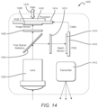
- FIG. 14 is a block diagram illustrating another example compact perception device in accordance with one embodiment of the present disclosure.
- FIG. 15 is a flowchart illustrating a method performed by a compact perception device for perceiving an external environment in accordance with some embodiments of the present disclosure.
- Coupled to is intended to include both direct coupling (in which two elements that are coupled to each other contact each other) and indirect coupling (in which at least one additional element is located between the two elements). Therefore, the terms “coupled to” and “coupled with” are used synonymously. Within the context of a networked environment where two or more components or devices are able to exchange data, the terms “coupled to” and “coupled with” are also used to mean “communicatively coupled with”, possibly via one or more intermediary devices.
- first means “first,” “second,” etc. to describe various elements, these elements should not be limited by the terms. These terms are only used to distinguish one element from another.
- a first mirror could be termed a second mirror and, similarly, a second mirror could be termed a first mirror, without departing from the scope of the various described examples.
- the first mirror and the second mirror can both be mirrors and, in some cases, can be separate and different mirrors.
- inventive subject matter is considered to include all possible combinations of the disclosed elements. As such, if one embodiment comprises elements A, B, and C, and another embodiment comprises elements B and D, then the inventive subject matter is also considered to include other remaining combinations of A, B, C, or D, even if not explicitly discussed herein.
- transitional term “comprising” means to have as parts or members, or to be those parts or members. As used herein, the transitional term “comprising” is inclusive or open-ended and does not exclude additional, unrecited elements or method steps.
- servers services, interfaces, engines, modules, clients, peers, portals, platforms, or other systems formed from computing devices. It should be appreciated that the use of such terms is deemed to represent one or more computing devices having at least one processor (e.g., ASIC, FPGA, PLD, DSP, x86, ARM, RISC-V, ColdFire, GPU, multi-core processors, etc.) configured to execute software instructions stored on a computer readable tangible, non-transitory medium (e.g., hard drive, solid state drive, RAM, flash, ROM, etc.).
- processor e.g., ASIC, FPGA, PLD, DSP, x86, ARM, RISC-V, ColdFire, GPU, multi-core processors, etc.
- a computer readable tangible, non-transitory medium e.g., hard drive, solid state drive, RAM, flash, ROM, etc.
- a server can include one or more computers operating as a web server, database server, or other type of computer server in a manner to fulfill described roles, responsibilities, or functions.
- the various servers, systems, databases, or interfaces can exchange data using standardized protocols or algorithms, possibly based on HTTP, HTTPS, AES, public-private key exchanges, web service APIs, known financial transaction protocols, or other electronic information exchanging methods. Data exchanges can be conducted over a packet-switched network, a circuit-switched network, the Internet, LAN, WAN, VPN, or other type of network.
- any language directed to a computer should be read to include any suitable combination of computing devices or network platforms, including servers, interfaces, systems, databases, agents, peers, engines, controllers, modules, or other types of computing devices operating individually or collectively.
- the computing devices comprise a processor configured to execute software instructions stored on a tangible, non-transitory computer readable storage medium (e.g., hard drive, FPGA, PLA, solid state drive, RAM, flash, ROM, etc.).
- the software instructions configure or program the computing device to provide the roles, responsibilities, or other functionality as discussed below with respect to the disclosed apparatus.
- the disclosed technologies can be embodied as a computer program product that includes a non-transitory computer readable medium storing the software instructions that causes a processor to execute the disclosed steps associated with implementations of computer-based algorithms, processes, methods, or other instructions.
- the various servers, systems, databases, or interfaces exchange data using standardized protocols or algorithms, possibly based on HTTP, HTTPS, AES, public-private key exchanges, web service APIs, known financial transaction protocols, or other electronic information exchanging methods.
- Data exchanges among devices can be conducted over a packet-switched network, the Internet, LAN, WAN, VPN, or other type of packet switched network; a circuit switched network; cell switched network; or other type of networks.
- LiDAR devices and cameras are two types of commonly used sensors in assisted driving and autonomous driving technologies. Cameras can capture a scene with brightness and color, while LiDAR devices can capture a scene the depth information so that the distance to an object can be calculated. Cameras are now widely used in advanced driver-assistance systems (ADAS). Both LiDAR devices and cameras may be used in modern vehicles to assist drivers in visibility and spatial awareness.
- the data provided by the LiDAR devices and cameras can be used to, for example, provide parking assistance, assist in performing lane changes, provide the driver with information about detecting potential obstacles and hazards in blind spots around a moving vehicle, improve the driver's visibility around the rear end of the vehicle when backing up the vehicle, or the like.
- a vehicle has separate LiDAR and camera devices, each with its own separate optical components such as lenses, windows, mirrors, or the like to direct and process optical signals.
- Each device may also have its own sensors, processors, and/or circuit boards.
- the combination of the LiDAR and camera devices may be bulky with many optical components and other components.
- the combination may be difficult to satisfy compact sensor design requirements especially for many passenger vehicles.
- a LiDAR device and a camera can share certain optical components (e.g., a collection lens), thereby making the entire perception device much more compact than traditional designs.
- a single lens can be used to collect both visible light and infrared light.
- the visible light can be directed to an image sensor for further sensing and processing; and the infrared light can be directed to a depth sensor for further sensing and processing.
- the single lens collects both the visible light and the NIR light
- the field of view (FOV) for the image sensor and the depth sensor is naturally matched (e.g., they are the same). As such, no or minimum calibration for distortion is required. In turn, this also eliminates or reduces the downstream data fusion workload, thereby improving energy efficiency and computational efficiency of the entire system.
- FIG. 1 illustrates one or more exemplary LiDAR systems 110 disposed or included in a motor vehicle 100 .
- Motor vehicle 100 can be a vehicle having any automated level.
- motor vehicle 100 can be a partially automated vehicle, a highly automated vehicle, a fully automated vehicle, or a driverless vehicle.
- a partially automated vehicle can perform some driving functions without a human driver's intervention.
- a partially automated vehicle can perform blind-spot monitoring, lane keeping and/or lane changing operations, automated emergency braking, smart cruising and/or traffic following, or the like.
- Certain operations of a partially automated vehicle may be limited to specific applications or driving scenarios (e.g., limited to only freeway driving).
- a highly automated vehicle can generally perform all operations of a partially automated vehicle but with less limitations.
- a highly automated vehicle can also detect its own limits in operating the vehicle and ask the driver to take over the control of the vehicle when necessary.
- a fully automated vehicle can perform all vehicle operations without a driver's intervention but can also detect its own limits and ask the driver to take over when necessary.
- a driverless vehicle can operate on its own without any driver intervention.
- motor vehicle 100 comprises one or more LiDAR systems 110 and 120 A-F.
- LiDAR systems 110 and 120 A-F can be a scanning-based LiDAR system and/or a non-scanning LiDAR system (e.g., a flash LiDAR).
- a scanning-based LiDAR system scans one or more light beams in one or more directions (e.g., horizontal and vertical directions) to detect objects in a field-of-view (FOV).
- a non-scanning based LiDAR system transmits laser light to illuminate an FOV without scanning.
- a flash LiDAR is a type of non-scanning based LiDAR system.
- a flash LiDAR can transmit laser light to simultaneously illuminate an FOV using a single light pulse or light shot.
- a LiDAR system is often an essential sensor of a vehicle that is at least partially automated.
- motor vehicle 100 may include a single LiDAR system 110 (e.g., without LiDAR systems 120 A-F) disposed at the highest position of the vehicle (e.g., at the vehicle roof). Disposing LiDAR system 110 at the vehicle roof facilitates a 360-degree scanning around vehicle 100 .
- motor vehicle 100 can include multiple LiDAR systems, including two or more of systems 110 and/or 120 A-F. As shown in FIG. 1 , in one embodiment, multiple LiDAR systems 110 and/or 120 A-F are attached to vehicle 100 at different locations of the vehicle.
- LiDAR system 120 A is attached to vehicle 100 at the front right corner; LiDAR system 120 B is attached to vehicle 100 at the front center; LiDAR system 120 C is attached to vehicle 100 at the front left corner; LiDAR system 120 D is attached to vehicle 100 at the right-side rear view mirror; LiDAR system 120 E is attached to vehicle 100 at the left-side rear view mirror; and/or LiDAR system 120 F is attached to vehicle 100 at the back center.
- LiDAR systems 110 and 120 A-F are independent LiDAR systems having their own respective laser sources, control electronics, transmitters, receivers, and/or steering mechanisms. In other embodiments, some of LiDAR systems 110 and 120 A-F can share one or more components, thereby forming a distributed sensor system.
- optical fibers are used to deliver laser light from a centralized laser source to all LiDAR systems. It is understood that one or more LiDAR systems can be distributed and attached to a vehicle in any desired manner and FIG. 1 only illustrates one embodiment.
- LiDAR systems 120 D and 120 E may be attached to the B-pillars of vehicle 100 instead of the rear-view mirrors.
- LiDAR system 120 B may be attached to the windshield of vehicle 100 instead of the front bumper.
- FIG. 2 is a block diagram 200 illustrating interactions between vehicle onboard LiDAR system(s) 210 and multiple other systems including a vehicle perception and planning system 220 .
- LiDAR system(s) 210 can be mounted on or integrated to a vehicle.
- LiDAR system(s) 210 include sensor(s) that scan laser light to the surrounding environment to measure the distance, angle, and/or velocity of objects. Based on the scattered light that returned to LiDAR system(s) 210 , it can generate sensor data (e.g., image data or 3D point cloud data) representing the perceived external environment.
- sensor data e.g., image data or 3D point cloud data
- LiDAR system(s) 210 can include one or more of short-range LiDAR sensors, medium-range LiDAR sensors, and long-range LiDAR sensors.
- a short-range LiDAR sensor measures objects located up to about 20-40 meters from the LiDAR sensor.
- Short-range LiDAR sensors can be used for, e.g., monitoring nearby moving objects (e.g., pedestrians crossing street in a school zone), parking assistance applications, or the like.
- a medium-range LiDAR sensor measures objects located up to about 100-150 meters from the LiDAR sensor.
- Medium-range LiDAR sensors can be used for, e.g., monitoring road intersections, assistance for merging onto or leaving a freeway, or the like.
- a long-range LiDAR sensor measures objects located up to about 150-300 meters.
- Long-range LiDAR sensors are typically used when a vehicle is travelling at high speed (e.g., on a freeway), such that the vehicle's control systems may only have a few seconds (e.g., 6-8 seconds) to respond to any situations detected by the LiDAR sensor.
- the LiDAR sensor data can be provided to vehicle perception and planning system 220 via a communication path 213 for further processing and controlling the vehicle operations.
- Communication path 213 can be any wired or wireless communication links that can transfer data.
- vehicle onboard sensor(s) 230 are used to provide additional sensor data separately or together with LiDAR system(s) 210 .
- Other vehicle onboard sensors 230 may include, for example, one or more camera(s) 232 , one or more radar(s) 234 , one or more ultrasonic sensor(s) 236 , and/or other sensor(s) 238 .
- Camera(s) 232 can take images and/or videos of the external environment of a vehicle.
- Camera(s) 232 can take, for example, high-definition (HD) videos having millions of pixels in each frame. A camera produces monochrome or color images and videos.
- HD high-definition
- Color information may be important in interpreting data for some situations (e.g., interpreting images of traffic lights). Color information may not be available from other sensors such as LiDAR or radar sensors.
- Camera(s) 232 can include one or more of narrow-focus cameras, wider-focus cameras, side-facing cameras, infrared cameras, fisheye cameras, or the like.
- the image and/or video data generated by camera(s) 232 can also be provided to vehicle perception and planning system 220 via communication path 233 for further processing and controlling the vehicle operations.
- Communication path 233 can be any wired or wireless communication links that can transfer data.
- Other vehicle onboard sensos(s) 230 can also include radar sensor(s) 234 .
- Radar sensor(s) 234 use radio waves to determine the range, angle, and velocity of objects. Radar sensor(s) 234 produce electromagnetic waves in the radio or microwave spectrum. The electromagnetic waves reflect off an object and some of the reflected waves return to the radar sensor, thereby providing information about the object's position and velocity.
- Radar sensor(s) 234 can include one or more of short-range radar(s), medium-range radar(s), and long-range radar(s).
- a short-range radar measures objects located at about 0.1-30 meters from the radar.
- a short-range radar is useful in detecting objects located nearby the vehicle, such as other vehicles, buildings, walls, pedestrians, bicyclists, etc.
- a short-range radar can be used to detect a blind spot, assist in lane changing, provide rear-end collision warning, assist in parking, provide emergency braking, or the like.
- a medium-range radar measures objects located at about 30-80 meters from the radar.
- a long-range radar measures objects located at about 80-200 meters.
- Medium- and/or long-range radars can be useful in, for example, traffic following, adaptive cruise control, and/or highway automatic braking.
- Sensor data generated by radar sensor(s) 234 can also be provided to vehicle perception and planning system 220 via communication path 233 for further processing and controlling the vehicle operations.
- Other vehicle onboard sensor(s) 230 can also include ultrasonic sensor(s) 236 .
- Ultrasonic sensor(s) 236 use acoustic waves or pulses to measure object located external to a vehicle. The acoustic waves generated by ultrasonic sensor(s) 236 are transmitted to the surrounding environment. At least some of the transmitted waves are reflected off an object and return to the ultrasonic sensor(s) 236 . Based on the return signals, a distance of the object can be calculated.
- Ultrasonic sensor(s) 236 can be useful in, for example, check blind spot, identify parking spots, provide lane changing assistance into traffic, or the like. Sensor data generated by ultrasonic sensor(s) 236 can also be provided to vehicle perception and planning system 220 via communication path 233 for further processing and controlling the vehicle operations.
- one or more other sensor(s) 238 may be attached in a vehicle and may also generate sensor data.
- Other sensor(s) 238 may include, for example, global positioning systems (GPS), inertial measurement units (IMU), or the like.
- Sensor data generated by other sensor(s) 238 can also be provided to vehicle perception and planning system 220 via communication path 233 for further processing and controlling the vehicle operations.
- communication path 233 may include one or more communication links to transfer data between the various sensor(s) 230 and vehicle perception and planning system 220 .
- sensor data from other vehicle onboard sensor(s) 230 can be provided to vehicle onboard LiDAR system(s) 210 via communication path 231 .
- LiDAR system(s) 210 may process the sensor data from other vehicle onboard sensor(s) 230 .
- sensor data from camera(s) 232 , radar sensor(s) 234 , ultrasonic sensor(s) 236 , and/or other sensor(s) 238 may be correlated or fused with sensor data LiDAR system(s) 210 , thereby at least partially offloading the sensor fusion process performed by vehicle perception and planning system 220 .
- other configurations may also be implemented for transmitting and processing sensor data from the various sensors (e.g., data can be transmitted to a cloud service for processing and then the processing results can be transmitted back to the vehicle perception and planning system 220 ).
- sensors onboard other vehicle(s) 250 are used to provide additional sensor data separately or together with LiDAR system(s) 210 .
- two or more nearby vehicles may have their own respective LiDAR sensor(s), camera(s), radar sensor(s), ultrasonic sensor(s), etc.
- Nearby vehicles can communicate and share sensor data with one another. Communications between vehicles are also referred to as V2V (vehicle to vehicle) communications.
- sensor data generated by other vehicle(s) 250 can be communicated to vehicle perception and planning system 220 and/or vehicle onboard LiDAR system(s) 210 , via communication path 253 and/or communication path 251 , respectively.
- Communication paths 253 and 251 can be any wired or wireless communication links that can transfer data.
- Sharing sensor data facilitates a better perception of the environment external to the vehicles. For instance, a first vehicle may not sense a pedestrian that is a behind a second vehicle but is approaching the first vehicle. The second vehicle may share the sensor data related to this pedestrian with the first vehicle such that the first vehicle can have additional reaction time to avoid collision with the pedestrian.
- data generated by sensors onboard other vehicle(s) 250 may be correlated or fused with sensor data generated by LiDAR system(s) 210 , thereby at least partially offloading the sensor fusion process performed by vehicle perception and planning system 220 .
- intelligent infrastructure system(s) 240 are used to provide sensor data separately or together with LiDAR system(s) 210 .
- Certain infrastructures may be configured to communicate with a vehicle to convey information and vice versa. Communications between a vehicle and infrastructures are generally referred to as V2I (vehicle to infrastructure) communications.
- intelligent infrastructure system(s) 240 may include an intelligent traffic light that can convey its status to an approaching vehicle in a message such as “changing to yellow in 5 seconds.”
- Intelligent infrastructure system(s) 240 may also include its own LiDAR system mounted near an intersection such that it can convey traffic monitoring information to a vehicle. For example, a left-turning vehicle at an intersection may not have sufficient sensing capabilities because some of its own sensors may be blocked by traffics in the opposite direction.
- sensors of intelligent infrastructure system(s) 240 can provide useful, and sometimes vital, data to the left-turning vehicle.
- data may include, for example, traffic conditions, information of objects in the direction the vehicle is turning to, traffic light status and predictions, or the like.
- These sensor data generated by intelligent infrastructure system(s) 240 can be provided to vehicle perception and planning system 220 and/or vehicle onboard LiDAR system(s) 210 , via communication paths 243 and/or 241 , respectively.
- Communication paths 243 and/or 241 can include any wired or wireless communication links that can transfer data.
- sensor data from intelligent infrastructure system(s) 240 may be transmitted to LiDAR system(s) 210 and correlated or fused with sensor data generated by LiDAR system(s) 210 , thereby at least partially offloading the sensor fusion process performed by vehicle perception and planning system 220 .
- V2V and V2I communications described above are examples of vehicle-to-X (V2X) communications, where the “X” represents any other devices, systems, sensors, infrastructure, or the like that can share data with a vehicle.
- vehicle perception and planning system 220 receives sensor data from one or more of LiDAR system(s) 210 , other vehicle onboard sensor(s) 230 , other vehicle(s) 250 , and/or intelligent infrastructure system(s) 240 .
- sensor fusion sub-system 222 can generate a 360-degree model using multiple images or videos captured by multiple cameras disposed at different positions of the vehicle.
- Sensor fusion sub-system 222 obtains sensor data from different types of sensors and uses the combined data to perceive the environment more accurately.
- a vehicle onboard camera 232 may not capture a clear image because it is facing the sun or a light source (e.g., another vehicle's headlight during nighttime) directly.
- a LiDAR system 210 may not be affected as much and therefore sensor fusion sub-system 222 can combine sensor data provided by both camera 232 and LiDAR system 210 , and use the sensor data provided by LiDAR system 210 to compensate the unclear image captured by camera 232 .
- a radar sensor 234 may work better than a camera 232 or a LiDAR system 210 . Accordingly, sensor fusion sub-system 222 may use sensor data provided by the radar sensor 234 to compensate the sensor data provided by camera 232 or LiDAR system 210 .
- sensor data generated by other vehicle onboard sensor(s) 230 may have a lower resolution (e.g., radar sensor data) and thus may need to be correlated and confirmed by LiDAR system(s) 210 , which usually has a higher resolution.
- LiDAR system(s) 210 which usually has a higher resolution.
- a sewage cover also referred to as a manhole cover
- vehicle perception and planning system 220 may not be able to determine whether the object is an obstacle that the vehicle needs to avoid.
- High-resolution sensor data generated by LiDAR system(s) 210 thus can be used to correlated and confirm that the object is a sewage cover and causes no harm to the vehicle.
- Vehicle perception and planning system 220 further comprises an object classifier 223 .
- object classifier 223 can detect and classify the objects and estimate the positions of the objects.
- object classifier 233 can use machine-learning based techniques to detect and classify objects. Examples of the machine-learning based techniques include utilizing algorithms such as region-based convolutional neural networks (R-CNN), Fast R-CNN, Faster R-CNN, histogram of oriented gradients (HOG), region-based fully convolutional network (R-FCN), single shot detector (SSD), spatial pyramid pooling (SPP-net), and/or You Only Look Once (Yolo).
- Vehicle perception and planning system 220 further comprises a road detection sub-system 224 .
- Road detection sub-system 224 localizes the road and identifies objects and/or markings on the road. For example, based on raw or fused sensor data provided by radar sensor(s) 234 , camera(s) 232 , and/or LiDAR system(s) 210 , road detection sub-system 224 can build a 3D model of the road based on machine-learning techniques (e.g., pattern recognition algorithms for identifying lanes). Using the 3D model of the road, road detection sub-system 224 can identify objects (e.g., obstacles or debris on the road) and/or markings on the road (e.g., lane lines, turning marks, crosswalk marks, or the like).
- objects e.g., obstacles or debris on the road
- markings on the road e.g., lane lines, turning marks, crosswalk marks, or the like.
- Vehicle perception and planning system 220 further comprises a localization and vehicle posture sub-system 225 .
- localization and vehicle posture sub-system 225 can determine position of the vehicle and the vehicle's posture. For example, using sensor data from LiDAR system(s) 210 , camera(s) 232 , and/or GPS data, localization and vehicle posture sub-system 225 can determine an accurate position of the vehicle on the road and the vehicle's six degrees of freedom (e.g., whether the vehicle is moving forward or backward, up or down, and left or right).
- high-definition (HD) maps are used for vehicle localization. HD maps can provide highly detailed, three-dimensional, computerized maps that pinpoint a vehicle's location.
- localization and vehicle posture sub-system 225 can determine precisely the vehicle's current position (e.g., which lane of the road the vehicle is currently in, how close it is to a curb or a sidewalk) and predict vehicle's future positions.
- Vehicle perception and planning system 220 further comprises obstacle predictor 226 .
- Objects identified by object classifier 223 can be stationary (e.g., a light pole, a road sign) or dynamic (e.g., a moving pedestrian, bicycle, another car). For moving objects, predicting their moving path or future positions can be important to avoid collision.
- Obstacle predictor 226 can predict an obstacle trajectory and/or warn the driver or the vehicle planning sub-system 228 about a potential collision. For example, if there is a high likelihood that the obstacle's trajectory intersects with the vehicle's current moving path, obstacle predictor 226 can generate such a warning.
- Obstacle predictor 226 can use a variety of techniques for making such a prediction.
- Such techniques include, for example, constant velocity or acceleration models, constant turn rate and velocity/acceleration models, Kalman Filter and Extended Kalman Filter based models, recurrent neural network (RNN) based models, long short-term memory (LSTM) neural network based models, encoder-decoder RNN models, or the like.
- RNN recurrent neural network
- LSTM long short-term memory
- vehicle perception and planning system 220 further comprises vehicle planning sub-system 228 .
- Vehicle planning sub-system 228 can include a route planner, a driving behaviors planner, and a motion planner.
- the route planner can plan the route of a vehicle based on the vehicle's current location data, target location data, traffic information, etc.
- the driving behavior planner adjusts the timing and planned movement based on how other objects might move, using the obstacle prediction results provided by obstacle predictor 226 .
- the motion planner determines the specific operations the vehicle needs to follow.
- the planning results are then communicated to vehicle control system 280 via vehicle interface 270 .
- the communication can be performed through communication paths 223 and 271 , which include any wired or wireless communication links that can transfer data.
- Vehicle control system 280 controls the vehicle's steering mechanism, throttle, brake, etc., to operate the vehicle according to the planned route and movement.
- Vehicle perception and planning system 220 may further comprise a user interface 260 , which provides a user (e.g., a driver) access to vehicle control system 280 to, for example, override or take over control of the vehicle when necessary.
- User interface 260 can communicate with vehicle perception and planning system 220 , for example, to obtain and display raw or fused sensor data, identified objects, vehicle's location/posture, etc. These displayed data can help a user to better operate the vehicle.
- User interface 260 can communicate with vehicle perception and planning system 220 and/or vehicle control system 280 via communication paths 221 and 261 respectively, which include any wired or wireless communication links that can transfer data. It is understood that the various systems, sensors, communication links, and interfaces in FIG. 2 can be configured in any desired manner and not limited to the configuration shown in FIG. 2 .
- FIG. 3 is a block diagram illustrating an exemplary LiDAR system 300 .
- LiDAR system 300 can be used to implement LiDAR system 110 , 120 A-F, and/or 210 shown in FIGS. 1 and 2 .
- LiDAR system 300 comprises a laser source 310 , a transmitter 320 , an optical receiver and light detector 330 , a steering system 340 , and a control circuitry 350 . These components are coupled together using communications paths 312 , 314 , 322 , 332 , 343 , 352 , and 362 .
- These communications paths include communication links (wired or wireless, bidirectional or unidirectional) among the various LiDAR system components, but need not be physical components themselves.
- the communications paths can be implemented by one or more electrical wires, buses, or optical fibers
- the communication paths can also be wireless channels or free-space optical paths so that no physical communication medium is present.
- communication path 314 between laser source 310 and transmitter 320 may be implemented using one or more optical fibers.
- Communication paths 332 and 352 may represent optical paths implemented using free space optical components and/or optical fibers.
- communication paths 312 , 322 , 342 , and 362 may be implemented using one or more electrical wires that carry electrical signals.
- the communications paths can also include one or more of the above types of communication mediums (e.g., they can include an optical fiber and a free-space optical component, or include one or more optical fibers and one or more electrical wires).
- LiDAR system 300 can also include other components not depicted in FIG. 3 , such as power buses, power supplies, LED indicators, switches, etc. Additionally, other communication connections among components may be present, such as a direct connection between light source 310 and optical receiver and light detector 330 to provide a reference signal so that the time from when a light pulse is transmitted until a return light pulse is detected can be accurately measured.
- Laser source 310 outputs laser light for illuminating objects in a field of view (FOV).
- Laser source 310 can be, for example, a semiconductor-based laser (e.g., a diode laser) and/or a fiber-based laser.
- a semiconductor-based laser can be, for example, an edge emitting laser (EEL), a vertical cavity surface emitting laser (VCSEL), or the like.
- a fiber-based laser is a laser in which the active gain medium is an optical fiber doped with rare-earth elements such as erbium, ytterbium, neodymium, dysprosium, praseodymium, thulium and/or holmium.
- a fiber laser is based on double-clad fibers, in which the gain medium forms the core of the fiber surrounded by two layers of cladding.
- the double-clad fiber allows the core to be pumped with a high-power beam, thereby enabling the laser source to be a high power fiber laser source.
- laser source 310 comprises a master oscillator (also referred to as a seed laser) and power amplifier (MOPA).
- the power amplifier amplifies the output power of the seed laser.
- the power amplifier can be a fiber amplifier, a bulk amplifier, or a semiconductor optical amplifier.
- the seed laser can be a diode laser (e.g., a Fabry-Perot cavity laser, a distributed feedback laser), a solid-state bulk laser, or a tunable external-cavity diode laser.
- laser source 310 can be an optically pumped microchip laser. Microchip lasers are alignment-free monolithic solid-state lasers where the laser crystal is directly contacted with the end mirrors of the laser resonator.
- a microchip laser is typically pumped with a laser diode (directly or using a fiber) to obtain the desired output power.
- a microchip laser can be based on neodymium-doped yttrium aluminum garnet (Y 3 Al 5 O 12 ) laser crystals (i.e., Nd:YAG), or neodymium-doped vanadate (i.e., ND:YVO 4 ) laser crystals.
- FIG. 4 is a block diagram illustrating an exemplary fiber-based laser source 400 having a seed laser and one or more pumps (e.g., laser diodes) for pumping desired output power.
- Fiber-based laser source 400 is an example of laser source 310 depicted in FIG. 3 .
- fiber-based laser source 400 comprises a seed laser 402 to generate initial light pulses of one or more wavelengths (e.g., 1550 nm), which are provided to a wavelength-division multiplexor (WDM) 404 via an optical fiber 403 .
- WDM wavelength-division multiplexor
- Fiber-based laser source 400 further comprises a pump 406 for providing laser power (e.g., of a different wavelength, such as 980 nm) to WDM 404 via an optical fiber 405 .
- WDM wavelength-division multiplexor
- WDM 404 multiplexes the light pulses provided by seed laser 402 and the laser power provided by pump 406 onto a single optical fiber 407 .
- the output of WDM 404 can then be provided to one or more pre-amplifier(s) 408 via optical fiber 407 .
- Pre-amplifier(s) 408 can be optical amplifier(s) that amplify optical signals (e.g., with about 20-30 dB gain). In some embodiments, pre-amplifier(s) 408 are low noise amplifiers.
- Pre-amplifier(s) 408 output to a combiner 410 via an optical fiber 409 .
- Combiner 410 combines the output laser light of pre-amplifier(s) 408 with the laser power provided by pump 412 via an optical fiber 411 .
- Combiner 410 can combine optical signals having the same wavelength or different wavelengths.
- One example of a combiner is a WDM.
- Combiner 410 provides pulses to a booster amplifier 414 , which produces output light pulses via optical fiber 410 .
- the booster amplifier 414 provides further amplification of the optical signals.
- the outputted light pulses can then be transmitted to transmitter 320 and/or steering mechanism 340 (shown in FIG. 3 ).
- FIG. 4 illustrates one exemplary configuration of fiber-based laser source 400 .
- Laser source 400 can have many other configurations using different combinations of one or more components shown in FIG. 4 and/or other components not shown in FIG. 4 (e.g., other components such as power supplies, lens, filters, splitters, combiners, etc.).
- fiber-based laser source 400 can be controlled (e.g., by control circuitry 350 ) to produce pulses of different amplitudes based on the fiber gain profile of the fiber used in fiber-based laser source 400 .
- Communication path 312 couples fiber-based laser source 400 to control circuitry 350 (shown in FIG. 3 ) so that components of fiber-based laser source 400 can be controlled by or otherwise communicate with control circuitry 350 .
- fiber-based laser source 400 may include its own dedicated controller. Instead of control circuitry 350 communicating directly with components of fiber-based laser source 400 , a dedicated controller of fiber-based laser source 400 communicates with control circuitry 350 and controls and/or communicates with the components of fiber-based light source 400 .
- Fiber-based light source 400 can also include other components not shown, such as one or more power connectors, power supplies, and/or power lines.
- typical operating wavelengths of laser source 310 comprise, for example, about 850 nm, about 905 nm, about 940 nm, about 1064 nm, and about 1550 nm.
- the upper limit of maximum usable laser power is set by the U.S. FDA (U.S. Food and Drug Administration) regulations.
- the optical power limit at 1550 nm wavelength is much higher than those of the other aforementioned wavelengths. Further, at 1550 nm, the optical power loss in a fiber is low. There characteristics of the 1550 nm wavelength make it more beneficial for long-range LiDAR applications.
- the amount of optical power output from laser source 310 can be characterized by its peak power, average power, and the pulse energy.
- the peak power is the ratio of pulse energy to the width of the pulse (e.g., full width at half maximum or FWHM). Thus, a smaller pulse width can provide a larger peak power for a fixed amount of pulse energy.
- a pulse width can be in the range of nanosecond or picosecond.
- the average power is the product of the energy of the pulse and the pulse repetition rate (PRR). As described in more detail below, the PRR represents the frequency of the pulsed laser light.
- the PRR typically corresponds to the maximum range that a LiDAR system can measure.
- Laser source 310 can be configured to produce pulses at high PRR to meet the desired number of data points in a point cloud generated by the LiDAR system.
- Laser source 310 can also be configured to produce pulses at medium or low PRR to meet the desired maximum detection distance.
- Wall plug efficiency (WPE) is another factor to evaluate the total power consumption, which may be a key indicator in evaluating the laser efficiency.
- WPE Wall plug efficiency
- FIG. 1 multiple LiDAR systems may be attached to a vehicle, which may be an electrical-powered vehicle or a vehicle otherwise having limited fuel or battery power supply. Therefore, high WPE and intelligent ways to use laser power are often among the important considerations when selecting and configuring laser source 310 and/or designing laser delivery systems for vehicle-mounted LiDAR applications.
- Laser source 310 can be configured to include many other types of light sources (e.g., laser diodes, short-cavity fiber lasers, solid-state lasers, and/or tunable external cavity diode lasers) that are configured to generate one or more light signals at various wavelengths.
- light source 310 comprises amplifiers (e.g., pre-amplifiers and/or booster amplifiers), which can be a doped optical fiber amplifier, a solid-state bulk amplifier, and/or a semiconductor optical amplifier. The amplifiers are configured to receive and amplify light signals with desired gains.
- LiDAR system 300 further comprises a transmitter 320 .
- Laser source 310 provides laser light (e.g., in the form of a laser beam) to transmitter 320 .
- the laser light provided by laser source 310 can be amplified laser light with a predetermined or controlled wavelength, pulse repetition rate, and/or power level.
- Transmitter 320 receives the laser light from laser source 310 and transmits the laser light to steering mechanism 340 with low divergence.
- transmitter 320 can include, for example, optical components (e.g., lens, fibers, mirrors, etc.) for transmitting laser beams to a field-of-view (FOV) directly or via steering mechanism 340 . While FIG. 3 illustrates transmitter 320 and steering mechanism 340 as separate components, they may be combined or integrated as one system in some embodiments. Steering mechanism 340 is described in more detail below.
- transmitter 320 often comprises a collimating lens configured to collect the diverging laser beams and produce more parallel optical beams with reduced or minimum divergence.
- the collimated optical beams can then be further directed through various optics such as mirrors and lens.
- a collimating lens may be, for example, a single plano-convex lens or a lens group.
- the collimating lens can be configured to achieve any desired properties such as the beam diameter, divergence, numerical aperture, focal length, or the like.
- a beam propagation ratio or beam quality factor (also referred to as the M2 factor) is used for measurement of laser beam quality.
- the M2 factor represents a degree of variation of a beam from an ideal Gaussian beam.
- the M2 factor reflects how well a collimated laser beam can be focused on a small spot, or how well a divergent laser beam can be collimated. Therefore, laser source 310 and/or transmitter 320 can be configured to meet, for example, a scan resolution requirement while maintaining the desired M2 factor.
- One or more of the light beams provided by transmitter 320 are scanned by steering mechanism 340 to a FOV.
- Steering mechanism 340 scans light beams in multiple dimensions (e.g., in both the horizontal and vertical dimension) to facilitate LiDAR system 300 to map the environment by generating a 3D point cloud.
- the laser light scanned to an FOV may be scattered or reflected by an object in the FOV. At least a portion of the scattered or reflected light returns to LiDAR system 300 .
- FIG. 3 further illustrates an optical receiver and light detector 330 configured to receive the return light.
- Optical receiver and light detector 330 comprises an optical receiver that is configured to collect the return light from the FOV.
- the optical receiver can include optics (e.g., lens, fibers, mirrors, etc.) for receiving, redirecting, focus, amplifying, and/or filtering return light from the FOV.
- optics e.g., lens, fibers, mirrors, etc.
- the optical receiver often includes a collection lens (e.g., a single plano-convex lens or a lens group) to collect and/or focus the collected return light onto a light detector.
- a light detector detects the return light focused by the optical receiver and generates current and/or voltage signals proportional to the incident intensity of the return light. Based on such current and/or voltage signals, the depth information of the object in the FOV can be derived.
- One exemplary method for deriving such depth information is based on the direct TOF (time of flight), which is described in more detail below.
- a light detector may be characterized by its detection sensitivity, quantum efficiency, detector bandwidth, linearity, signal to noise ratio (SNR), overload resistance, interference immunity, etc.
- SNR signal to noise ratio
- the light detector can be configured or customized to have any desired characteristics.
- optical receiver and light detector 330 can be configured such that the light detector has a large dynamic range while having a good linearity.
- the light detector linearity indicates the detector's capability of maintaining linear relationship between input optical signal power and the detector's output.
- a detector having good linearity can maintain a linear relationship over a large dynamic input optical signal range.
- a light detector structure can be a PIN based structure, which has a undoped intrinsic semiconductor region (i.e., an “i” region) between a p-type semiconductor and an n-type semiconductor region.
- Other light detector structures comprise, for example, a APD (avalanche photodiode) based structure, a PMT (photomultiplier tube) based structure, a SiPM (Silicon photomultiplier) based structure, a SPAD (single-photon avalanche diode) base structure, and/or quantum wires.
- APD active photodiode
- PMT photomultiplier tube
- SiPM Silicon photomultiplier
- SPAD single-photon avalanche diode
- material systems used in a light detector Si, InGaAs, and/or Si/Ge based materials can be used. It is understood that many other detector structures and/or material systems can be used in optical receiver and light detector 330 .
- a light detector may have an internal gain such that the input signal is amplified when generating an output signal.
- noise may also be amplified due to the light detector's internal gain.
- Common types of noise include signal shot noise, dark current shot noise, thermal noise, and amplifier noise (TIA).
- optical receiver and light detector 330 may include a pre-amplifier that is a low noise amplifier (LNA).
- the pre-amplifier may also include a TIA-transimpedance amplifier, which converts a current signal to a voltage signal.
- input equivalent noise or noise equivalent power (NEP) measures how sensitive the light detector is to weak signals.
- the NEP of a light detector specifies the power of the weakest signal that can be detected and therefore it in turn specifies the maximum range of a LiDAR system.
- various light detector optimization techniques can be used to meet the requirement of LiDAR system 300 . Such optimization techniques may include selecting different detector structures, materials, and/or implement signal processing techniques (e.g., filtering, noise reduction, amplification, or the like).
- signal processing techniques e.g., filtering, noise reduction, amplification, or the like.
- coherent detection can also be used for a light detector.
- Coherent detection allows for detecting amplitude and phase information of the received light by interfering the received light with a local oscillator. Coherent detection can improve detection sensitivity and noise immunity.
- FIG. 3 further illustrates that LiDAR system 300 comprises steering mechanism 340 .
- steering mechanism 340 directs light beams from transmitter 320 to scan an FOV in multiple dimensions.
- a steering mechanism is referred to as a raster mechanism or a scanning mechanism. Scanning light beams in multiple directions (e.g., in both the horizontal and vertical directions) facilitates a LiDAR system to map the environment by generating an image or a 3D point cloud.
- a steering mechanism can be based on mechanical scanning and/or solid-state scanning. Mechanical scanning uses rotating mirrors to steer the laser beam or physically rotate the LiDAR transmitter and receiver (collectively referred to as transceiver) to scan the laser beam.
- Solid-state scanning directs the laser beam to various positions through the FOV without mechanically moving any macroscopic components such as the transceiver.
- Solid-state scanning mechanisms include, for example, optical phased arrays based steering and flash LiDAR based steering. In some embodiments, because solid-state scanning mechanisms do not physically move macroscopic components, the steering performed by a solid-state scanning mechanism may be referred to as effective steering.
- a LiDAR system using solid-state scanning may also be referred to as a non-mechanical scanning or simply non-scanning LiDAR system (a flash LiDAR system is an exemplary non-scanning LiDAR system).
- Steering mechanism 340 can be used with the transceiver (e.g., transmitter 320 and optical receiver and light detector 330 ) to scan the FOV for generating an image or a 3D point cloud.
- a two-dimensional mechanical scanner can be used with a single-point or several single-point transceivers.
- a single-point transceiver transmits a single light beam or a small number of light beams (e.g., 2-8 beams) to the steering mechanism.
- a two-dimensional mechanical steering mechanism comprises, for example, polygon mirror(s), oscillating mirror(s), rotating prism(s), rotating tilt mirror surface(s), or a combination thereof.
- steering mechanism 340 may include non-mechanical steering mechanism(s) such as solid-state steering mechanism(s).
- steering mechanism 340 can be based on tuning wavelength of the laser light combined with refraction effect, and/or based on reconfigurable grating/phase array.
- steering mechanism 340 can use a single scanning device to achieve two-dimensional scanning or two devices combined to realize two-dimensional scanning.
- a one-dimensional mechanical scanner can be used with an array or a large number of single-point transceivers.
- the transceiver array can be mounted on a rotating platform to achieve 360-degree horizontal field of view.
- a static transceiver array can be combined with the one-dimensional mechanical scanner.
- a one-dimensional mechanical scanner comprises polygon mirror(s), oscillating mirror(s), rotating prism(s), rotating tilt mirror surface(s) for obtaining a forward-looking horizontal field of view. Steering mechanisms using mechanical scanners can provide robustness and reliability in high volume production for automotive applications.
- a two-dimensional transceiver can be used to generate a scan image or a 3D point cloud directly.
- a stitching or micro shift method can be used to improve the resolution of the scan image or the field of view being scanned.
- signals generated at one direction e.g., the horizontal direction
- signals generated at the other direction e.g., the vertical direction
- steering mechanism 340 comprise one or more optical redirection elements (e.g., mirrors or lens) that steer return light signals (e.g., by rotating, vibrating, or directing) along a receive path to direct the return light signals to optical receiver and light detector 330 .
- the optical redirection elements that direct light signals along the transmitting and receiving paths may be the same components (e.g., shared), separate components (e.g., dedicated), and/or a combination of shared and separate components. This means that in some cases the transmitting and receiving paths are different although they may partially overlap (or in some cases, substantially overlap).
- LiDAR system 300 further comprises control circuitry 350 .
- Control circuitry 350 can be configured and/or programmed to control various parts of the LiDAR system 300 and/or to perform signal processing.
- control circuitry 350 can be configured and/or programmed to perform one or more control operations including, for example, controlling laser source 310 to obtain desired laser pulse timing, repetition rate, and power; controlling steering mechanism 340 (e.g., controlling the speed, direction, and/or other parameters) to scan the FOV and maintain pixel registration/alignment; controlling optical receiver and light detector 330 (e.g., controlling the sensitivity, noise reduction, filtering, and/or other parameters) such that it is an optimal state; and monitoring overall system health/status for functional safety.
- controlling laser source 310 to obtain desired laser pulse timing, repetition rate, and power
- controlling steering mechanism 340 e.g., controlling the speed, direction, and/or other parameters
- controlling optical receiver and light detector 330 e.g., controlling the sensitivity, noise reduction, filtering, and/or other parameters
- Control circuitry 350 can also be configured and/or programmed to perform signal processing to the raw data generated by optical receiver and light detector 330 to derive distance and reflectance information, and perform data packaging and communication to vehicle perception and planning system 220 (shown in FIG. 2 ). For example, control circuitry 350 determines the time it takes from transmitting a light pulse until a corresponding return light pulse is received; determines when a return light pulse is not received for a transmitted light pulse; determines the direction (e.g., horizontal and/or vertical information) for a transmitted/return light pulse; determines the estimated range in a particular direction; and/or determines any other type of data relevant to LiDAR system 300 .
- direction e.g., horizontal and/or vertical information
- LiDAR system 300 can be disposed in a vehicle, which may operate in many different environments including hot or cold weather, rough road conditions that may cause intense vibration, high or low humidifies, dusty areas, etc. Therefore, in some embodiments, optical and/or electronic components of LiDAR system 300 (e.g., optics in transmitter 320 , optical receiver and light detector 330 , and steering mechanism 340 ) are disposed or configured in such a manner to maintain long term mechanical and optical stability. For example, components in LiDAR system 300 may be secured and sealed such that they can operate under all conditions a vehicle may encounter.
- an anti-moisture coating and/or hermetic sealing may be applied to optical components of transmitter 320 , optical receiver and light detector 330 , and steering mechanism 340 (and other components that are susceptible to moisture).
- housing(s), enclosure(s), and/or window can be used in LiDAR system 300 for providing desired characteristics such as hardness, ingress protection (IP) rating, self-cleaning capability, resistance to chemical and resistance to impact, or the like.
- IP ingress protection
- efficient and economical methodologies for assembling LiDAR system 300 may be used to meet the LiDAR operating requirements while keeping the cost low.
- LiDAR system 300 can include other functional units, blocks, or segments, and can include variations or combinations of these above functional units, blocks, or segments.
- LiDAR system 300 can also include other components not depicted in FIG. 3 , such as power buses, power supplies, LED indicators, switches, etc.
- other connections among components may be present, such as a direct connection between light source 310 and optical receiver and light detector 330 so that light detector 330 can accurately measure the time from when light source 310 transmits a light pulse until light detector 330 detects a return light pulse.
- communications paths 312 , 314 , 322 , 332 , 342 , 352 , and 362 These components shown in FIG. 3 are coupled together using communications paths 312 , 314 , 322 , 332 , 342 , 352 , and 362 .
- These communications paths represent communication (bidirectional or unidirectional) among the various LiDAR system components but need not be physical components themselves. While the communications paths can be implemented by one or more electrical wires, busses, or optical fibers, the communication paths can also be wireless channels or open-air optical paths so that no physical communication medium is present.
- communication path 314 includes one or more optical fibers; communication path 352 represents an optical path; and communication paths 312 , 322 , 342 , and 362 are all electrical wires that carry electrical signals.
- the communication paths can also include more than one of the above types of communication mediums (e.g., they can include an optical fiber and an optical path, or one or more optical fibers and one or more electrical wires).
- an exemplary LiDAR system 500 includes a laser light source (e.g., a fiber laser), a steering system (e.g., a system of one or more moving mirrors), and a light detector (e.g., a photon detector with one or more optics).
- a laser light source e.g., a fiber laser
- a steering system e.g., a system of one or more moving mirrors
- a light detector e.g., a photon detector with one or more optics.
- LiDAR system 500 can be implemented using, for example, LiDAR system 300 described above.
- LiDAR system 500 transmits a light pulse 502 along light path 504 as determined by the steering system of LiDAR system 500 .
- light pulse 502 which is generated by the laser light source, is a short pulse of laser light.
- the signal steering system of the LiDAR system 500 is a pulsed-signal steering system.
- LiDAR systems can operate by generating, transmitting, and detecting light signals that are not pulsed and derive ranges to an object in the surrounding environment using techniques other than time-of-flight.
- some LiDAR systems use frequency modulated continuous waves (i.e., “FMCW”).
- FMCW frequency modulated continuous waves
- any of the techniques described herein with respect to time-of-flight based systems that use pulsed signals also may be applicable to LiDAR systems that do not use one or both of these techniques.
- FIG. 5 A e.g., illustrating a time-of-flight LiDAR system that uses light pulses
- light pulse 502 when light pulse 502 reaches object 506 , light pulse 502 scatters or reflects to generate a return light pulse 508 .
- Return light pulse 508 may return to system 500 along light path 510 .
- the time from when transmitted light pulse 502 leaves LiDAR system 500 to when return light pulse 508 arrives back at LiDAR system 500 can be measured (e.g., by a processor or other electronics, such as control circuitry 350 , within the LiDAR system).
- This time-of-flight combined with the knowledge of the speed of light can be used to determine the range/distance from LiDAR system 500 to the portion of object 506 where light pulse 502 scattered or reflected.
- LiDAR system 500 scans the external environment (e.g., by directing light pulses 502 , 522 , 526 , 530 along light paths 504 , 524 , 528 , 532 , respectively).
- LiDAR system 500 receives return light pulses 508 , 542 , 548 (which correspond to transmitted light pulses 502 , 522 , 530 , respectively).
- Return light pulses 508 , 542 , and 548 are generated by scattering or reflecting the transmitted light pulses by one of objects 506 and 514 .
- Return light pulses 508 , 542 , and 548 may return to LiDAR system 500 along light paths 510 , 544 , and 546 , respectively.
- the external environment within the detectable range e.g., the field of view between path 504 and 532 , inclusively
- can be precisely mapped or plotted e.g., by generating a 3D point cloud or images.
- a corresponding light pulse is not received for a particular transmitted light pulse, then it may be determined that there are no objects within a detectable range of LiDAR system 500 (e.g., an object is beyond the maximum scanning distance of LiDAR system 500 ).
- light pulse 526 may not have a corresponding return light pulse (as illustrated in FIG. 5 C ) because light pulse 526 may not produce a scattering event along its transmission path 528 within the predetermined detection range.
- LiDAR system 500 or an external system in communication with LiDAR system 500 (e.g., a cloud system or service), can interpret the lack of return light pulse as no object being disposed along light path 528 within the detectable range of LiDAR system 500 .
- light pulses 502 , 522 , 526 , and 530 can be transmitted in any order, serially, in parallel, or based on other timings with respect to each other.
- FIG. 5 B depicts transmitted light pulses as being directed in one dimension or one plane (e.g., the plane of the paper)
- LiDAR system 500 can also direct transmitted light pulses along other dimension(s) or plane(s).
- LiDAR system 500 can also direct transmitted light pulses in a dimension or plane that is perpendicular to the dimension or plane shown in FIG. 5 B , thereby forming a 2-dimensional transmission of the light pulses.
- This 2-dimensional transmission of the light pulses can be point-by-point, line-by-line, all at once, or in some other manner.
- a point cloud or image from a 1-dimensional transmission of light pulses e.g., a single horizontal line
- 2-dimensional data e.g., (1) data from the horizontal transmission direction and (2) the range or distance to objects
- 3-dimensional data e.g., (1) data from the horizontal transmission direction, (2) data from the vertical transmission direction, and (3) the range or distance to objects.
- a LiDAR system performing an n-dimensional transmission of light pulses generates (n+1) dimensional data.
- the LiDAR system can measure the depth of an object or the range/distance to the object, which provides the extra dimension of data. Therefore, a 2D scanning by a LiDAR system can generate a 3D point cloud for mapping the external environment of the LiDAR system.
- the density of a point cloud refers to the number of measurements (data points) per area performed by the LiDAR system.
- a point cloud density relates to the LiDAR scanning resolution.
- a larger point cloud density, and therefore a higher resolution, is desired at least for the region of interest (ROI).
- the density of points in a point cloud or image generated by a LiDAR system is equal to the number of pulses divided by the field of view.
- the field of view can be fixed. Therefore, to increase the density of points generated by one set of transmission-receiving optics (or transceiver optics), the LiDAR system may need to generate a pulse more frequently. In other words, a light source with a higher pulse repetition rate (PRR) is needed.
- PRR pulse repetition rate
- the farthest distance that the LiDAR system can detect may be limited. For example, if a return signal from a distant object is received after the system transmits the next pulse, the return signals may be detected in a different order than the order in which the corresponding signals are transmitted, thereby causing ambiguity if the system cannot correctly correlate the return signals with the transmitted signals.
- the farthest distance the LiDAR system can detect may be 300 meters and 150 meters for 500 kHz and 1 MHz, respectively.
- the density of points of a LiDAR system with 500 kHz repetition rate is half of that with 1 MHz.
- this example demonstrates that, if the system cannot correctly correlate return signals that arrive out of order, increasing the repetition rate from 500 kHz to 1 MHz (and thus improving the density of points of the system) may reduce the detection range of the system.
- Various techniques are used to mitigate the tradeoff between higher PRR and limited detection range. For example, multiple wavelengths can be used for detecting objects in different ranges. Optical and/or signal processing techniques are also used to correlate between transmitted and return light signals.
- Various systems, apparatus, and methods described herein may be implemented using digital circuitry, or using one or more computers using well-known computer processors, memory units, storage devices, computer software, and other components.
- a computer includes a processor for executing instructions and one or more memories for storing instructions and data.
- a computer may also include, or be coupled to, one or more mass storage devices, such as one or more magnetic disks, internal hard disks and removable disks, magneto-optical disks, optical disks, etc.
- Various systems, apparatus, and methods described herein may be implemented using computers operating in a client-server relationship.
- the client computers are located remotely from the server computers and interact via a network.
- the client-server relationship may be defined and controlled by computer programs running on the respective client and server computers.
- client computers can include desktop computers, workstations, portable computers, cellular smartphones, tablets, or other types of computing devices.
- Various systems, apparatus, and methods described herein may be implemented using a computer program product tangibly embodied in an information carrier, e.g., in a non-transitory machine-readable storage device, for execution by a programmable processor; and the method processes and steps described herein, including one or more of the steps of embodiments 24-43 set forth below, may be implemented using one or more computer programs that are executable by such a processor.
- a computer program is a set of computer program instructions that can be used, directly or indirectly, in a computer to perform a certain activity or bring about a certain result.
- a computer program can be written in any form of programming language, including compiled or interpreted languages, and it can be deployed in any form, including as a stand-alone program or as a module, component, subroutine, or other unit suitable for use in a computing environment.
- Apparatus 600 comprises a processor 610 operatively coupled to a persistent storage device 620 and a main memory device 630 .
- Processor 610 controls the overall operation of apparatus 600 by executing computer program instructions that define such operations.
- the computer program instructions may be stored in persistent storage device 620 , or other computer-readable medium, and loaded into main memory device 630 when execution of the computer program instructions is desired.
- processor 610 may be used to implement one or more components and systems described herein, such as control circuitry 350 (shown in FIG. 3 ), vehicle perception and planning system 220 (shown in FIG. 2 ), and vehicle control system 280 (shown in FIG.
- Apparatus 600 also includes one or more network interfaces 680 for communicating with other devices via a network. Apparatus 600 may also include one or more input/output devices 690 that enable user interaction with apparatus 600 (e.g., display, keyboard, mouse, speakers, buttons, etc.).
- Processor 610 may include both general and special purpose microprocessors and may be the sole processor or one of multiple processors of apparatus 600 .
- Processor 610 may comprise one or more central processing units (CPUs), and one or more graphics processing units (GPUs), which, for example, may work separately from and/or multi-task with one or more CPUs to accelerate processing, e.g., for various image processing applications described herein.
- processor 610 , persistent storage device 620 , and/or main memory device 630 may include, be supplemented by, or incorporated in, one or more application-specific integrated circuits (ASICs) and/or one or more field programmable gate arrays (FPGAs).
- ASICs application-specific integrated circuits
- FPGAs field programmable gate arrays
- Persistent storage device 620 and main memory device 630 each comprise a tangible non-transitory computer readable storage medium.
- Persistent storage device 620 , and main memory device 630 may each include high-speed random access memory, such as dynamic random access memory (DRAM), static random access memory (SRAM), double data rate synchronous dynamic random access memory (DDR RAM), or other random access solid state memory devices, and may include non-volatile memory, such as one or more magnetic disk storage devices such as internal hard disks and removable disks, magneto-optical disk storage devices, optical disk storage devices, flash memory devices, semiconductor memory devices, such as erasable programmable read-only memory (EPROM), electrically erasable programmable read-only memory (EEPROM), compact disc read-only memory (CD-ROM), digital versatile disc read-only memory (DVD-ROM) disks, or other non-volatile solid state storage devices.
- DRAM dynamic random access memory
- SRAM static random access memory
- DDR RAM double data rate synchronous dynamic random access memory
- Input/output devices 690 may include peripherals, such as a printer, scanner, display screen, etc.
- input/output devices 690 may include a display device such as a cathode ray tube (CRT), plasma or liquid crystal display (LCD) monitor for displaying information to a user, a keyboard, and a pointing device such as a mouse or a trackball by which the user can provide input to apparatus 600 .
- a display device such as a cathode ray tube (CRT), plasma or liquid crystal display (LCD) monitor for displaying information to a user, a keyboard, and a pointing device such as a mouse or a trackball by which the user can provide input to apparatus 600 .
- CTR cathode ray tube
- LCD liquid crystal display
- LiDAR system 300 may utilize one or more neural networks or other deep-learning techniques performed by processor 610 or other systems or apparatuses discussed herein.
- FIG. 6 is a high-level representation of some of the components of such a computer for illustrative purposes.
- FIGS. 7 - 10 illustrate various example locations of a vehicle to which a camera can be mounted to or integrated with. While FIGS. 7 - 10 use cameras as examples, it is understood that various embodiments of a compact perception device provided in this disclosure can also be mounted to, or integrated with, a vehicle at the illustrated locations or any other desired locations. Further, a compact perception device provided in this disclosure can also be mounted to, or integrated with, other moveable or stationary platforms, such as a drone, a ship, an airplane, a motorcycle, an infrastructure, a roadside structure, a parking structure, or the like.
- FIG. 7 illustrates a side view camera 702 mounted to the left front side (driver side) of a vehicle 700 in accordance with one embodiment of the present disclosure.
- the side view camera 702 can be positioned on a side of vehicle 700 above a fender of the front left tire.
- Camera 702 can be used to capture images and videos of a field-of-view (FOV) extending, for example, from a side area of the vehicle to an area behind the vehicle.
- FOV field-of-view
- FIG. 7 illustrates that camera 702 is located at the left front side of the vehicle, it is understood that one or more cameras can be mounted to, or integrated with, the vehicle at its right front side to capture images or videos of objects located on the other side of the vehicle.
- FOV field-of-view
- FIG. 8 illustrates a side view camera 802 mounted to a door frame 804 of a vehicle 800 in accordance with one embodiment of the present disclosure.
- camera 802 can be used to capture images and videos of a FOV extending, for example, from a side area of the vehicle to an area in front of the vehicle.
- camera 802 can provide image data associated with the objects (e.g., traffic, pedestrians, bicycles, etc.) in an area surrounding the vehicle.
- the FOV captured by camera 802 can be different from the FOV captured by camera 702 as described above in FIG. 7 .
- the two FOVs may or may not overlap with each other.
- FIG. 9 illustrates a surround-view camera 902 mounted to a side rear view mirror 904 of a vehicle 900 in accordance with one embodiment of the present disclosure.
- FIG. 10 illustrates another surround-view camera 1002 mounted to a front grille 1004 or a front bumper of vehicle 900 .
- cameras 902 and 1002 with or without other surround-view cameras mount to the vehicle 900 , can be used to provide a bird's eye view of the vehicle. Such a bird's eye view of the vehicle can be useful to assist parking of the vehicle.
- vehicle 900 may be mounted with 4-6 surround-view cameras.
- vehicle 900 can include camera 902 mounted to a rear-view mirror, another camera (not shown) mounted to the other rear-view mirror, camera 1002 mounted to the front grille 1004 , and another camera (not shown) mounted to the rear bumper. At least some of these surround-view cameras are wide-angle cameras.
- the surround-view cameras can be configured to capture images and videos of their respective FOVs. For instance, camera 902 captures images and/or videos of an FOV at the left side of vehicle 900 ; camera 1002 captures images and/or videos of another FOV in front of vehicle 900 ; another camera captures images and/or videos of another FOV at the right side of vehicle 900 ; and another camera captures images and/or videos of another FOV behind the vehicle 900 .
- Image and/or video signals generated by the surround-view cameras can then be transmitted to a processor.
- the processor is configured to analyze and combine the signals from different surround-view cameras to provide a synthesized bird's eye view of the vehicle.
- FIG. 11 illustrates an exemplary vehicle dashboard display 1100 based on data provided by one or more surround-view cameras mount to the vehicle according to one embodiment of the present disclosure.
- the right side of display 1100 shows an example bird's eye view image 1104 synthesized using data provided by the surround-view cameras mounted to the vehicle (e.g., cameras 902 and 1002 shown in FIGS. 9 and 10 ).
- the left side of display 1100 shows an image 1102 of an FOV behind the vehicle.
- cameras 702 , 802 , 902 , and 1002 shown in FIGS. 9 - 11 are mounted to, or integrated with, a vehicle. While FIGS. 7 - 10 uses cameras as illustration, various embodiments of a compact perception device provided in this disclosure can also be mounted to, or integrated with, a vehicle at the illustrated locations.
- the compact perception device may include at least a portion of a LiDAR device to provide depth data of an FOV and at least a portion of a camera to provide image data of the FOV.
- the compact perception device described herein can be configured to fit into any of the above-described locations of a vehicle, and/or any other desired locations (e.g., a pillar, a front or rear end bumper, a rear-view mirror, a fender, a roof, a door frame, a vehicle corner, etc.).
- any other desired locations e.g., a pillar, a front or rear end bumper, a rear-view mirror, a fender, a roof, a door frame, a vehicle corner, etc.
- FIG. 12 is a block diagram illustrating an example compact perception device 1200 according to some embodiments of the present disclosure.
- Device 1200 comprises a lens 1202 , a first optical reflector 1204 , a second optical reflector 1206 , an image sensor 1208 , a depth sensor 1210 , a transmitter 1212 , a printed circuit board (PCB) 1214 , a data bus 1216 , and a processor 1218 .
- transmitter 1212 is configured to emit laser light to an FOV external to compact perception device 1200 .
- Transmitter 1212 can be implemented by one or more of laser source 310 , transmitter 320 , steering mechanism 340 , and control circuitry 350 as described above.
- transmitter 1212 can include at least a part of a flash LiDAR device, at least a part of a scanning LiDAR device, or any type of device that emits laser light.
- Transmitter 1212 can perform optical, mechanical, and/or electrical steering of laser light to the FOV.
- transmitter 1212 can include at least one solid state based LiDAR device configured to perform electronic scanning.
- Transmitter 1212 may also include a LiDAR device configured to perform optical scanning using one or more optical components such as polygon mirror, oscillation mirror, and/or other steering mechanisms described above.
- Transmitter 1212 can be configured to perform scanning in one or two dimensions.
- the laser light emitted by transmitter 1212 comprises near infrared range (NIR) light or infrared light.
- the light may be continuous wave light or pulsed laser light.
- Near infrared light is electromagnetic radiation with a wavelength that lies between about 780 to about 950 nm and is invisible to the human eye. It is understood that the laser light emitted by transmitter 1212 can comprise infrared light having wavelengths from 780 nm to 1 mm. While the below descriptions use NIR light as an illustration, it is further understood that the descriptions also apply to infrared light and/or light having wavelengths other than the visible light.
- the laser light emitted from transmitter 1212 may be reflected or scattered by one or more objects in an FOV (not shown).
- the reflected or scattered light forms return light, similar to those shown in FIGS. 5 A- 5 C .
- the return light has substantially the same wavelength as the emitted light.
- the return light is also NIR light.
- the return light can be collected by lens 1202 .
- lens 1202 can also be configured to collect visible light.
- the visible light can have a wavelength range of about 380 nm to about 750 nm.
- Lens 1202 may be configured such that it can collect both visible light and NIR light.
- the focal length of lens 1202 can be configured to accommodate the slightly longer wavelength of the NIR light as compared to the visible light.
- lens 1202 may include one or more lens or a lens group. Some of the lenses in the lens group may be optimized for focus the visible light, and some other lenses in the lens group may be optimized for focus the NIR light. The lens in the lens group may thus have different focal lengths.
- both visible light and NIR light are directed from lens 1202 to first optical reflector 1204 .
- FIG. 12 shows that first optical reflector 1204 is directly coupled to lens 1202 , it is understood that one or more additional optical components may be disposed between lens 1202 and first optical reflector 1204 to redirect light as desired.
- first optical reflector 1204 can be located based on the NIR light focal length of lens 1202 such that the collected NIR light is focused onto first optical reflector 1204 .
- Lens 1202 can further be configured such that the visible light, or a substantial portion of it, passes through first optical reflector 1204 and focuses onto image sensor 1208 .
- device 1200 further comprises a lens group 1205 and a lens group 1215 for correcting optical aberration caused by different wavelengths.
- lens groups 1205 and 1215 may include any combination of one or more lens (e.g., convex lens, concave lens, spherical lens, aspherical lens, wide angle lens, etc.).
- the visible light directed by lens 1202 due to its shorter wavelength, may refract more than the NIR light. Therefore, the visible light passing through lens 1202 may not be focused properly onto image sensor 1205 .
- Lens group 1205 can be positioned between first optical reflector 1204 and image sensor 1205 to properly focus the visible light to image sensor 1208 .
- first optical reflector 1204 can be configured to reflect a substantial portion of the NIR light directed by lens 1202 and pass a substantial portion of the visible light directed by lens 1202 .
- first optical reflector 1204 is a dichroic mirror that has significant different reflection or transmission properties at two different wavelengths.
- a dichroic mirror can pass a substantial portion of light having one wavelength and reflect a substantial portion of light having another wavelength.
- first optical reflector 1204 can be primarily an infrared mirror having metallic coatings such as Aluminum, Silver, or Gold, for reflecting a substantial portion of the NIR light.
- First optical reflector 1204 can further have protective coatings such as SiO or SiO2.
- first optical reflector 1204 may also have a layer of anti-reflection coating to allow the visible light to pass through.
- the AR coating may be provided at a certain area (e.g., center area) or all areas of first optical reflector 1204 .
- the AR coating may be configured according to the visible light wavelength.
- First optical reflector 1204 can also be a partial reflection mirror.
- the visible light passes through first optical reflector 1204 and is directed to image sensor 1208 (e.g., via lens set 1205 ).
- Image sensor 1208 can be a complementary metal oxide semiconductor (CMOS) image sensor or a CCD image sensor.
- CMOS complementary metal oxide semiconductor
- the image sensor 1208 detects the visible light and converts the light signals to electrical signals.
- the collected NIR light, or a substantial portion thereof, is reflected from first optical reflector 1204 to a second optical reflector 1206 .
- Second optical reflector 1206 can reflect light that is directed by first optical reflector 1204 to a depth sensor 1210 . In this case, second optical reflector 1206 reflects the NIR light toward depth sensor 1210 .
- the NIR light redirected by second optical reflector 1206 may not be properly focused on depth sensor 1210 .
- a lens group 1215 may be disposed between second optical reflector 1206 and depth sensor 1210 to properly focus the NIR light onto depth sensor 1210 .
- Second optical reflector 1206 can also be an infrared mirror having metallic coatings such as Aluminum, Silver, or Gold, for reflecting a substantial portion of the NIR light. It is understood that while FIG. 12 shows that the NIR light is reflected by first optical reflector 1204 to second optical reflector 1206 directly, one or more additional optics may be disposed in between to redirect light as desired. Similarly, one or more additional optics may be disposed in between second optical reflector 1206 and depth sensor 1210 .
- Depth sensor 1210 is configured to detect the NIR light reflected by first optical reflector 1204 and directed by second optical reflector 1206 .
- Depth sensor 1210 can include any of the detector described above.
- depth sensor 1210 can include a PIN based light detector structure, a APD (avalanche photodiode) based structure, a PMT (photomultiplier tube) based structure, a SiPM (Silicon photomultiplier) based structure, a SPAD (single-photon avalanche diode) base structure, and/or quantum wires.
- Si, InGaAs, and/or Si/Ge based materials can be used.
- Depth sensor 1210 converts NIR light signals to electrical signals.
- the receiving paths for visible light and for NIR light are partially shared by using a same lens 1202 (or a lens group), first optical reflector 1204 , and second optical reflector 1206 .
- image sensor 1208 and depth sensor 1214 can be mounted to the same printed circuit board (PCB) 1214 .
- Image sensor 1208 converts visible light to electrical signals for generating a camera image and therefore functions as a camera.
- Depth sensor 1214 converts NIR light to electrical signals for generating a 3D point cloud and therefore functions as a LiDAR device. Accordingly, by sharing many of the components for generating both a camera image and a LiDAR point cloud, the entire perception device 1200 can be very compact in size.
- the FOVs for both image sensor 1208 and depth sensor 1214 are substantially the same. Accordingly, this reduces or eliminates the requirement to perform calibration between the depth sensor 1214 and the image sensor 1208 . As a result, the complexity of data fusion between data generated by the two sensors is greatly reduced.
- the images captured by the image sensor 1208 and the depth sensor 1214 can be naturally matched by this configuration.
- image sensor 1208 generates image data using visible light collected by lens 1202 and passed by first optical reflector 1204 .
- Depth sensor 1210 generates depth data using NIR light collected by lens 1202 and reflected by both first optical reflector 1204 and second optical reflector 1206 .
- Image data may represent the 2-dimensional view of the FOV and include color information (red, green blue, or RGB).
- Depth data may represent a 3-dimension view of the FOV by including distance measurement (also referred to as depth).
- compact perception device 1200 further includes an electrical circuitry comprising a PCB 1214 .
- a processor 1218 can be mounted on PCB 1214 (on the same side as the image sensor 1208 and depth sensor 1210 , or on a different side of PCB). Electrical wires can be routed from image sensor 1208 and depth sensor 1210 to processor 1218 .
- a single processor 1218 can be used to combine the image data and the depth data, thereby making the perception device 1200 more compact.
- compact perception device 1200 improves the processing efficiency and reduces processing power consumption.
- the output data from processor 1218 can be fused or merged data that include both color information and depth information of the FOV (e.g., red, green, blue, and depth data, or RGBD data). As shown in FIG. 12 , in one embodiment, the output data from processor 1218 can be communicated to a data bus 1216 , which delivers the data to other systems for further processing.
- compact perception device 1200 is steerable.
- transmitter 1212 and/or lens 1202 may be steerable to better direct light to, and collect light from, a desired FOV.
- the entire compact perception device 1200 is steerable to improve the light collection efficiency.
- compact perception device 1200 may be placed on a moveable platform that is configured to move and/or rotate at any directions and/or angles.
- FIG. 13 shows a compact perception device 1300 , which has a different configuration than device 1200 . Similar to device 1200 , device 1300 also includes a lens 1302 , a first optical reflector 1304 , a second optical reflector 1306 , an image sensor 1308 , a depth sensor 1310 , a transmitter 1312 , a printed circuit board (PCB) 1314 , a data bus 1316 , and a processor 1318 .
- Image sensor 1308 , depth sensor 1310 , transmitter 1312 , printed circuit board (PCB) 1314 , data bus 1316 , and processor 1318 can be substantially the same or similar to their counterparts shown in FIG. 12 , and are thus not repeatedly described.
- first optical reflector 1304 passes the collected NIR light and reflects the collected visible light.
- the NIR light is then directed to depth sensor 1310 and the visible light is directed to second optical reflector 1306 .
- Second optical reflector 1306 reflects the visible light to image sensor 1308 .
- the two optical reflectors shown in FIG. 13 are essentially swapped in position with each other.
- the image sensor and depth sensor of device 1300 are also swapped in position.
- first optical reflector 1304 can be located based on the visible light focal length of lens 1302 such that the visible light is focused onto first optical reflector 1304 .
- Lens 1302 can further be configured such that the NIR light, or a substantial portion of it, passes through first optical reflector 1304 and focuses on depth sensor 1310 .
- lens 1302 can also include a lens group with one or more lens optimized for focusing visible light and one or more other lenses optimized for focusing the NIR light.
- device 1300 may further comprises a lens group 1305 disposed between first optical reflector 1304 and depth sensor 1310 , and/or another lens group 1315 disposed between second optical reflector 1306 and image sensor 1308 for correcting optical aberration caused by different wavelengths.
- Each of these lens groups 1305 and 1315 may include any combination of one or more lens (e.g., convex lens, concave lens, spherical lens, aspherical lens, wide angle lens, etc.).
- first optical reflector 1304 can be configured to reflect a substantial portion of the visible light directed by lens 1302 and pass a substantial portion of the NIR light directed by lens 1302 .
- first optical reflector 1304 is a dichroic mirror that has significant different reflection or transmission properties at two different wavelengths.
- first optical reflector 1304 can be primarily a visible light mirror while being substantially transparent to NIR light having longer wavelength.
- first optical reflector 1304 may also have a layer of NIR anti-reflection coating to allow the NIR light to pass through.
- the NIR AR coating may be provided in certain (e.g., center area) or all areas of first optical reflector 1304 .
- First optical reflector 1304 can also be a partial reflection mirror.
- FIG. 14 illustrates a compact perception device 1400 , which includes a lens 1402 , a first optical reflector 1404 , an image sensor 1408 , a depth sensor 1410 , a transmitter 1412 , a first printed circuit board (PCB) 1414 , a data bus 1416 , a second PCB 1415 , and a processor 1418 .
- a compact perception device 1400 which includes a lens 1402 , a first optical reflector 1404 , an image sensor 1408 , a depth sensor 1410 , a transmitter 1412 , a first printed circuit board (PCB) 1414 , a data bus 1416 , a second PCB 1415 , and a processor 1418 .
- PCB printed circuit board
- Lens 1402 , first optical reflector 1404 , image sensor 1408 , depth sensor 1410 , transmitter 1412 , first PCB 1414 , data bus 1416 , and processor 1418 can be substantially the same or similar to their counterparts shown in FIGS. 12 and 13 , and are thus not repeatedly described.
- first optical reflector 1404 reflects a substantial portion of NIR light directed by lens 1402 .
- the reflected NIR light is directed to depth sensor 1410 directly, without the need of a second optical reflector.
- Depth sensor 1410 is mounted to a second PCB 1415 .
- second PCB 1415 can be a separate and distinct PCB from first PCB 1414 .
- image sensor 1408 and depth sensor 1410 are not mounted to the same PCB or aligned at the same plane. Instead, they can be positioned to be perpendicular to each other or at any other desired angles with respect to each other.
- Image sensor 1408 and depth sensor 1410 may be coupled to separate PCBs or may be coupled to a single flexible PCB.
- a cable, or a flexible PCB may connect the two PCBs 1414 and 1415 such that data can be transmitted between them.
- device 1400 further comprises a lens group 1405 and a lens group 1413 for correcting optical aberration caused by different wavelengths.
- lens groups 1405 and 1413 may include any combination of one or more lens (e.g., convex lens, concave lens, spherical lens, aspherical lens, wide angle lens, etc.).
- Lens group 1405 can facilitate to properly focus visible light onto image sensor 1408 and lens group 1413 can facilitate to properly focus the NIR light onto depth sensor 1410 . It is understood that the embodiment shown in FIG.
- first optical reflector 1404 reflects visible light, instead of NIR light.
- depth sensor 1410 can be mounted to PCB 1414 and image sensor 1408 can be mounted to PCB 1415 .
- Other configurations are also possible.
- the embodiment shown in FIG. 14 can further reduce the size of the compact perception device because it eliminates the second optical reflector.
- FIGS. 12 - 14 illustrate several embodiments of a compact perception device
- a compact perception device can have other configurations.
- one or more optical reflectors, one or more PCBs, one or more processors may be used and/or configured differently.
- the lens can be placed at different positions depending on vehicle mounting location of the compact perception device.
- a compact perception device is disposed in a single housing.
- the lens, the transmitter, optical reflector(s), PCB(s), processor(s), the image sensor, the depth sensor can all be packaged in a same housing.
- some of the components may be separately packaged in a different housing and/or located at a different part of the vehicle to which the compact perception device is mounted.
- FIG. 15 is a flowchart illustrating an example method 1500 performed by a compact perception device for perceiving an external environment.
- Method 1500 can be performed by any of the compact perception device described above or any other alternative configurations without departing from the principle of the method steps.
- a transmitter e.g., transmitters 1212 , 1312 , or 1412
- the emitted laser light may be scattered or reflected by objects in the FOV.
- the scattered and reflected light form return light that can be collected by a lens of the compact perception device.
- the emitter laser light and the return light can be in the infrared wavelength range (e.g., NIR light).
- a lens e.g., lens 1202 , 1302 , or 1402 collects both visible light and near infrared (NIR) light to obtain collected light including collected visible light and collected NIR light.
- NIR near infrared
- the lens and/or other components of the compact perception device is steerable so that it can improve the collection efficiency of the device.
- a first optical reflector e.g., 1204 , 1304 , or 1404 ) reflects one of the collected visible light or the collected NIR light, and pass the collected light that is not reflected by the first optical reflector.
- a second optical reflector (e.g., reflector 1206 or 1306 ) directs the collected light that is reflected by the first optical reflector to the image sensor or the depth sensor.
- the first optical reflector reflects the collected visible light and passes the collected the NIR light.
- the second optical reflector then reflects the collected visible light to the image sensor. This embodiment is shown in FIG. 13 .
- the first optical reflector reflects the collected NIR light and passes the collected visible light by the first optical reflector.
- the second optical reflector then reflects the collected NIR light to the depth sensor. This embodiment is shown in FIG. 12 .
- an image sensor detects the collected visible light directed by the first optical reflector to form image data.
- the collected NIR light directed by the first optical reflector to form depth data.
- an electrical circuitry coupled to the image sensor and depth sensor can combine the image data and the depth data. In one embodiment, combining the data includes encoding, by the electrical circuitry, the depth data and the image data into red, green, blue and depth (RGBD) data.
- the electrical circuitry may include one or more processors and one or more PCBs as shown in FIGS. 12 - 14 .
- step 1516 the combined data is transmitted via a data bus to other systems (e.g., one or more sub-systems of vehicle perception and planning system 220 ) for further processing.
- other systems e.g., one or more sub-systems of vehicle perception and planning system 220 .
- steps shown in FIG. 15 are for illustration only. Some of the steps can be removed, reordered, and/or altered depending on the particular configurations or design requirements. Additional steps can be added to method 1500 without departing from the principle of the method.
Abstract
Description
Claims (22)
Priority Applications (2)
| Application Number | Priority Date | Filing Date | Title |
|---|---|---|---|
| US18/105,781 US11871130B2 (en) | 2022-03-25 | 2023-02-03 | Compact perception device |
| PCT/US2023/012537 WO2023183094A1 (en) | 2022-03-25 | 2023-02-07 | Compact perception device |
Applications Claiming Priority (2)
| Application Number | Priority Date | Filing Date | Title |
|---|---|---|---|
| US202263323962P | 2022-03-25 | 2022-03-25 | |
| US18/105,781 US11871130B2 (en) | 2022-03-25 | 2023-02-03 | Compact perception device |
Publications (2)
| Publication Number | Publication Date |
|---|---|
| US20230328403A1 US20230328403A1 (en) | 2023-10-12 |
| US11871130B2 true US11871130B2 (en) | 2024-01-09 |
Family
ID=85556779
Family Applications (1)
| Application Number | Title | Priority Date | Filing Date |
|---|---|---|---|
| US18/105,781 Active US11871130B2 (en) | 2022-03-25 | 2023-02-03 | Compact perception device |
Country Status (2)
| Country | Link |
|---|---|
| US (1) | US11871130B2 (en) |
| WO (1) | WO2023183094A1 (en) |
Citations (227)
| Publication number | Priority date | Publication date | Assignee | Title |
|---|---|---|---|---|
| US3897150A (en) | 1972-04-03 | 1975-07-29 | Hughes Aircraft Co | Scanned laser imaging and ranging system |
| GB1427164A (en) | 1972-02-19 | 1976-03-10 | Nippon Electric Co | Interference eliminating system for radars |
| GB2000411A (en) | 1977-06-15 | 1979-01-04 | Impulsphysik Gmbh | Ceilometric method and apparatus |
| US4464048A (en) | 1981-03-25 | 1984-08-07 | Barr & Stroud Limited | Laser rangefinders |
| US5006721A (en) | 1990-03-23 | 1991-04-09 | Perceptron, Inc. | Lidar scanning system |
| US5157451A (en) | 1991-04-01 | 1992-10-20 | John Taboada | Laser imaging and ranging system using two cameras |
| US5319434A (en) | 1992-12-30 | 1994-06-07 | Litton Systems, Inc. | Laser rangefinder apparatus with fiber optic interface |
| US5369661A (en) | 1991-02-07 | 1994-11-29 | Nippon Steel Corporation | Semiconductor laser-pumped solid state laser system and optical coupling system coupling semiconductor laser with optical fiber |
| US5442358A (en) | 1991-08-16 | 1995-08-15 | Kaman Aerospace Corporation | Imaging lidar transmitter downlink for command guidance of underwater vehicle |
| US5546188A (en) | 1992-11-23 | 1996-08-13 | Schwartz Electro-Optics, Inc. | Intelligent vehicle highway system sensor and method |
| US5579153A (en) | 1992-04-27 | 1996-11-26 | Pirelli Cavi S.P.A. | Optical power limiting amplifier |
| US5657077A (en) | 1993-02-18 | 1997-08-12 | Deangelis; Douglas J. | Event recording system with digital line camera |
| US5793491A (en) | 1992-12-30 | 1998-08-11 | Schwartz Electro-Optics, Inc. | Intelligent vehicle highway system multi-lane sensor and method |
| US5838239A (en) | 1992-10-20 | 1998-11-17 | Robotic Vision Systems, Inc. | System for detecting ice or snow on surface which specularly reflects light |
| US5864391A (en) | 1996-04-04 | 1999-01-26 | Denso Corporation | Radar apparatus and a vehicle safe distance control system using this radar apparatus |
| US5926259A (en) | 1995-05-04 | 1999-07-20 | Bushnell Corporation | Laser range finder with target quality display |
| US5936756A (en) | 1996-01-10 | 1999-08-10 | Ricoh Company Ltd. | Compact scanning optical system |
| US6163378A (en) | 1999-06-14 | 2000-12-19 | Khoury; Jehad | Spectroscopic time integrative correlation for rapid medical diagnostic and universal image analysis |
| US6317202B1 (en) | 1998-11-12 | 2001-11-13 | Denso Corporation | Automotive radar detecting lane mark and frontal obstacle |
| EP0757257B1 (en) | 1995-07-31 | 2002-05-29 | Raytheon Company | Laser range finder receiver |
| EP1237305A2 (en) | 2001-02-28 | 2002-09-04 | KiloLambda IP Limited | Multi-wavelength light source |
| US20020136251A1 (en) | 2001-01-25 | 2002-09-26 | Science And Technology Corporation | Automatic gain control system for use with multiple wavelength signal detector |
| US6650404B1 (en) | 2002-05-28 | 2003-11-18 | Analog Modules, Inc. | Laser rangefinder receiver |
| US20040119020A1 (en) | 2001-12-21 | 2004-06-24 | Andrew Bodkin | Multi-mode optical imager |
| US20040135992A1 (en) | 2002-11-26 | 2004-07-15 | Munro James F. | Apparatus for high accuracy distance and velocity measurement and methods thereof |
| US20050033497A1 (en) | 2003-08-06 | 2005-02-10 | Stopczynski Lawrence Gerard | Method of controlling an external object sensor for an automotive vehicle |
| US20050190424A1 (en) | 2004-02-27 | 2005-09-01 | Sick Ag | Method and device for optical scanning of objects |
| US20050195383A1 (en) | 1994-05-23 | 2005-09-08 | Breed David S. | Method for obtaining information about objects in a vehicular blind spot |
| CN1677050A (en) | 2004-03-31 | 2005-10-05 | 株式会社电装 | Object detector of vehicle |
| US20060071846A1 (en) | 2003-05-30 | 2006-04-06 | Yakayuki Yanagisawa | Coherent laser radar |
| US20060132752A1 (en) | 2004-12-16 | 2006-06-22 | Kane David M | Micromechanical and related lidar apparatus and method, and fast light-routing components |
| US7128267B2 (en) | 2003-07-11 | 2006-10-31 | Sick Ag | Device for optical scanning of objects, especially markings |
| US20070091948A1 (en) | 2005-07-29 | 2007-04-26 | Aculight Corporation | Multi-stage optical amplifier having photonic-crystal waveguides for generation of high-power pulsed radiation and associated method |
| JP2007144667A (en) | 2005-11-24 | 2007-06-14 | Fuji Xerox Co Ltd | Image forming apparatus and formed image correcting method |
| US20070216995A1 (en) | 2006-03-16 | 2007-09-20 | Bollond Paul G | Optical fiber laser having improved efficiency |
| US7345271B2 (en) | 2002-09-25 | 2008-03-18 | Ibeo Automobile Sensor Gmbh | Optoelectric sensing device with common deflection device |
| US7375803B1 (en) * | 2006-05-18 | 2008-05-20 | Canesta, Inc. | RGBZ (red, green, blue, z-depth) filter system usable with sensor systems, including sensor systems with synthetic mirror enhanced three-dimensional imaging |
| EP1923721A1 (en) | 2005-08-15 | 2008-05-21 | Topcon Corporation | Measuring device |
| US20080174762A1 (en) | 2006-08-29 | 2008-07-24 | Jony Jiang Liu | Micro-mirror optical tracking and ranging system |
| US20080193135A1 (en) | 2007-02-14 | 2008-08-14 | Finisar Corporation | Collimated ball lenses for optical triplexers |
| US20090010644A1 (en) | 2002-02-01 | 2009-01-08 | Cubic Corporation | Integrated optical communication and range finding system and applications thereof |
| US7489885B2 (en) | 1995-03-27 | 2009-02-10 | Canon Kabushiki Kaisha | Coupling part, photosensitive drum, process cartridge and electrophotographic image forming apparatus |
| US20090051926A1 (en) | 2007-04-13 | 2009-02-26 | United States Of America As Represented By The Administrator Of The National Aeronautics And Spac | Multiple frequency optical mixer and demultiplexer and apparatus for remote sensing |
| US20090059201A1 (en) | 2007-08-28 | 2009-03-05 | Science Applications International Corporation | Full-Field Light Detection and Ranging Imaging System |
| US20090067453A1 (en) | 2005-04-07 | 2009-03-12 | Matsushita Electric Industrial Co., Ltd. | Laser Light Source and Optical Device |
| US20090147239A1 (en) | 2005-09-02 | 2009-06-11 | Neptec | Apparatus and method for tracking an object |
| US20090262760A1 (en) | 2005-01-20 | 2009-10-22 | Vladimir Krupkin | Laser Obstacle Ranging and Display |
| US20090316134A1 (en) | 2004-07-08 | 2009-12-24 | Michael Christopher E | Fiber laser ladar |
| US20100006780A1 (en) | 2008-05-06 | 2010-01-14 | U.S. Government As Represented By The Secretary Of The Army | Method and Apparatus for Enhanced Terahertz Radiation from High Stacking Fault Density |
| US20100020306A1 (en) | 2006-07-13 | 2010-01-28 | Velodyne Acoustics, Inc. | High definition lidar system |
| US20100020377A1 (en) | 2008-07-25 | 2010-01-28 | Spudnik, Inc. | Beam Scanning Based on Two-Dimensional Polygon Scanner for Display and Other Applications |
| US20100027602A1 (en) | 2008-07-31 | 2010-02-04 | United States Of America As Represented By The Administrator Of The National Aeronautics And Spac | Time delay and distance measurement |
| JP2010035385A (en) | 2008-07-31 | 2010-02-12 | Kyocera Mita Corp | Motor drive controller |
| EP2157445A2 (en) | 2008-08-19 | 2010-02-24 | Rosemount Aerospace Inc. | Lidar system using a pseudo-random pulse sequence |
| US20100053715A1 (en) | 2006-10-30 | 2010-03-04 | O'neill James | Scanning system for lidar |
| US20100128109A1 (en) | 2008-11-25 | 2010-05-27 | Banks Paul S | Systems And Methods Of High Resolution Three-Dimensional Imaging |
| US20100208244A1 (en) | 2008-05-09 | 2010-08-19 | Ball Aerospace & Technologies Corp. | Flash ladar system |
| US20100271614A1 (en) | 2006-01-27 | 2010-10-28 | Vijay Albuquerque | LIDAR system utilizing SOI-based opto-electronic components |
| US7880865B2 (en) | 2007-02-28 | 2011-02-01 | Denso Wave Incorporated | Laser radar apparatus for three-dimensional detection of objects |
| US7982881B2 (en) | 2005-12-06 | 2011-07-19 | Carl Zeiss Meditec Ag | Apparatus and method for interferometric measurement of a sample |
| US20110181864A1 (en) | 2008-07-04 | 2011-07-28 | Eads Deutschland Gmbh | Lidar method for measuring speeds and lidar device with time-controlled detection |
| EP2395368A1 (en) | 2010-06-11 | 2011-12-14 | Sick AG | Distance-measuring laser scanner for detecting objects in a surveillance range |
| KR20120013515A (en) | 2010-08-05 | 2012-02-15 | (주)이오시스템 | Device for compensating gain of avalanche photo diode in optic measuring device |
| US20120038903A1 (en) | 2010-08-16 | 2012-02-16 | Ball Aerospace & Technologies Corp. | Electronically steered flash lidar |
| US20120044476A1 (en) | 2008-05-09 | 2012-02-23 | Ball Aerospace & Technologies Corp. | Systems and methods of scene and action capture using imaging system incorporating 3d lidar |
| US20120124113A1 (en) | 2010-11-05 | 2012-05-17 | University of Maribor | LIGHT DETECTION AND RANGING (LiDAR)DATA COMPRESSION AND DECOMPRESSION METHODS AND APPARATUS |
| US20120221142A1 (en) | 2011-02-24 | 2012-08-30 | Mss, Inc. | Sequential Scanning Of Multiple Wavelengths |
| US20130107016A1 (en) | 2010-05-17 | 2013-05-02 | Iee International Electronics & Engineering S.A. | Scanning 3d imager |
| US20130116971A1 (en) | 2010-06-28 | 2013-05-09 | Fraunhofer-Gesellschaft Zur Foerderung Der Angewandten Forschung E.V. | Method for generating a signal for a distance measurement and method and system for distance measurement between a transmitter and a receiver |
| KR20130068224A (en) | 2011-12-15 | 2013-06-26 | 여우순엽 | The apparatus and method of monitoring with terrestrial lidar and reflectless totalstation |
| US20130241781A1 (en) | 2010-11-25 | 2013-09-19 | Nokia Corporation | Antenna apparatus and methods |
| US20130293867A1 (en) | 2009-09-23 | 2013-11-07 | Pixart Imaging Inc. | Distance-measuring device of measuring distance according to variation of imaging location and calibrating method thereof |
| US20130293946A1 (en) | 2012-05-01 | 2013-11-07 | Imra America, Inc. | Optical frequency ruler |
| US20130329279A1 (en) | 2004-03-31 | 2013-12-12 | Imra America, Inc. | Method and apparatus for controlling and protecting pulsed high power fiber amplifier systems |
| US20130342822A1 (en) | 2011-03-02 | 2013-12-26 | Toyota Jidosha Kabushiki Kaisha | Laser radar device |
| US20140078514A1 (en) | 2010-10-22 | 2014-03-20 | Neptec Design Group Ltd. | Wide angle bistatic scanning optical ranging sensor |
| US20140104594A1 (en) | 2009-07-28 | 2014-04-17 | Applied Concepts, Inc. | Lidar Measurement Device with Target Tracking and Method for Use of Same |
| US8749784B1 (en) | 2012-10-18 | 2014-06-10 | Checkpoint Technologies, Llc | Probing circuit features in sub-32 nm semiconductor integrated circuit |
| US20140347850A1 (en) | 2013-01-11 | 2014-11-27 | Lighting Science Group Corporation | Serially-connected light emitting diodes, methods of forming same, and luminaires containing same |
| US20140350836A1 (en) | 2013-05-24 | 2014-11-27 | Advance Scientific Concepts, Inc. | Automotive auxiliary ladar sensor |
| US20150078123A1 (en) | 2013-09-16 | 2015-03-19 | Appareo Systems, Llc | Synthetic underwater visualization system |
| US20150084805A1 (en) | 2012-03-19 | 2015-03-26 | Qinetiq Limited | Detection Techniques |
| US20150109803A1 (en) | 2013-10-23 | 2015-04-23 | Samsung Electronics Co., Ltd. | Semiconductor light emitting diode package and lighting device using the same |
| US20150116692A1 (en) | 2012-04-30 | 2015-04-30 | Michigan Aerospace Corporation | System and method for scan range gating |
| US20150139259A1 (en) | 2013-11-21 | 2015-05-21 | Christie Digital Systems Canada Inc. | Method, system and apparatus for automatically determining operating conditions of a periodically poled lithium niobate crystal in a laser system |
| US20150158489A1 (en) | 2013-12-09 | 2015-06-11 | Hyundai Motor Company | Method for object processing and vehicle supporting the same |
| US9065243B2 (en) | 2011-01-20 | 2015-06-23 | Nippon Telegraph And Telephone Corporation | Optical amplifier |
| EP2889642A1 (en) | 2013-12-16 | 2015-07-01 | Riegl Laser Measurement Systems GmbH | Method for distance measurement |
| US9086273B1 (en) | 2013-03-08 | 2015-07-21 | Google Inc. | Microrod compression of laser beam in combination with transmit lens |
| CN204758260U (en) | 2015-07-21 | 2015-11-11 | 北京杏林睿光科技有限公司 | Semiconductor laser structure of multitube core characteristic monitoring |
| US9194701B2 (en) | 2011-12-23 | 2015-11-24 | Leica Geosystems Ag | Distance-measuring device alignment |
| US20150338270A1 (en) | 2012-05-10 | 2015-11-26 | Voxtel, Inc. | Discriminating photo counts and dark counts in an avalanche photodiode |
| US20150355327A1 (en) | 2012-11-21 | 2015-12-10 | Nikon Metrology Nv | Scan mirrors for laser radar |
| CN204885804U (en) | 2015-07-21 | 2015-12-16 | 北京杏林睿光科技有限公司 | Multi -wavelength raman laser who restraints module and have this module is closed to narrow linewidth |
| US20160003946A1 (en) | 2014-07-03 | 2016-01-07 | Advanced Scientific Concepts, Inc. | Ladar sensor for a dense environment |
| US20160047900A1 (en) | 2014-08-15 | 2016-02-18 | US LADAR, Inc. | Method and System for Scanning Ladar Transmission with Pulse Modulation |
| US20160061855A1 (en) | 2013-04-16 | 2016-03-03 | Trajet Gmbh | Method for the combined determination of a speed and an image taken from a vehicle, and apparatus suitable therefor |
| US20160061935A1 (en) | 2014-08-28 | 2016-03-03 | Google Inc. | Methods and Systems for Vehicle Radar Coordination and Interference Reduction |
| US9304316B2 (en) | 2004-11-15 | 2016-04-05 | Apple Inc. | Method and device for scanning light |
| US20160100521A1 (en) | 2014-10-10 | 2016-04-14 | Irobot Corporation | Autonomous Robot Localization |
| US9316724B2 (en) | 2012-12-18 | 2016-04-19 | Sick Ag | Optoelectronic sensor for the detection of objects |
| US20160117048A1 (en) | 2014-09-26 | 2016-04-28 | Cypress Semiconductor Corporation | Background Light Detection for Optical Navigation Systems |
| US20160172819A1 (en) | 2014-12-12 | 2016-06-16 | Omron Corporation | Light amplifying device and laser processing apparatus |
| US20160178736A1 (en) | 2014-12-19 | 2016-06-23 | Hanwha Techwin Co., Ltd. | Lidar system |
| US20160226210A1 (en) | 2015-01-29 | 2016-08-04 | John J. Zayhowski | Systems and methods for light amplification |
| US20160227193A1 (en) | 2013-03-15 | 2016-08-04 | Uber Technologies, Inc. | Methods, systems, and apparatus for multi-sensory stereo vision for robotics |
| US20160245902A1 (en) | 2015-02-25 | 2016-08-25 | Abbie T. Watnik | Real-time processing and adaptable illumination lidar camera using a spatial light modulator |
| US20160291134A1 (en) | 2015-04-06 | 2016-10-06 | Google Inc. | Long Range Steerable LIDAR System |
| US20160313445A1 (en) | 2012-03-16 | 2016-10-27 | Advanced Scientific Concepts, Inc. | Personal ladar sensor |
| US20160327646A1 (en) | 2015-05-07 | 2016-11-10 | GM Global Technology Operations LLC | Pseudo random sequences in array lidar systems |
| US20170003116A1 (en) | 2015-06-30 | 2017-01-05 | Korea Research Institute Of Standards And Science | Apparatus for real-time non-contact non-destructive thickness measurement using terahertz wave |
| US20170003392A1 (en) | 2015-07-02 | 2017-01-05 | Texas Instruments Incorporated | Methods and Apparatus for LIDAR with DMD |
| JP2017003347A (en) | 2015-06-08 | 2017-01-05 | 日本信号株式会社 | Object detection device and object detection method |
| US9557856B2 (en) * | 2013-08-19 | 2017-01-31 | Basf Se | Optical detector |
| US9605998B2 (en) | 2014-09-03 | 2017-03-28 | Panasonic Intellectual Property Management Co., Ltd. | Measurement system |
| US9610786B2 (en) | 2012-01-19 | 2017-04-04 | Fujitsu Component Limited | Printer and method of controlling printer |
| US20170153319A1 (en) | 2015-11-30 | 2017-06-01 | Luminar Technologies, Inc. | Lidar system with distributed laser and multiple sensor heads |
| WO2017110417A1 (en) | 2015-12-21 | 2017-06-29 | 株式会社小糸製作所 | Image acquisition device for vehicles, control device, vehicle provided with image acquisition device for vehicles and control device, and image acquisition method for vehicles |
| CN206314210U (en) | 2016-11-25 | 2017-07-11 | 苏州迈威斯精密机械有限公司 | The bearing of hay mover head and the bearing clamp assembly of gear shaft assembly machine |
| JP2017138301A (en) | 2016-01-28 | 2017-08-10 | 株式会社デンソー | Laser rader device |
| US20170242104A1 (en) | 2016-02-18 | 2017-08-24 | Aeye, Inc. | Ladar Transmitter with Induced Phase Drift for Improved Gaze on Scan Area Portions |
| US20170307738A1 (en) | 2013-11-22 | 2017-10-26 | Uber Technologies, Inc. | Lidar scanner calibration |
| US9804284B2 (en) | 2013-09-12 | 2017-10-31 | Cgg Services Sas | Ghost-suppression optimized seismic source and method |
| US20170365105A1 (en) | 2016-06-17 | 2017-12-21 | Ford Global Technologies, Llc | Method and apparatus for inter-vehicular safety awareness and alert |
| US20170363741A1 (en) | 2014-12-09 | 2017-12-21 | Basf Se | Optical detector |
| US9869754B1 (en) | 2017-03-22 | 2018-01-16 | Luminar Technologies, Inc. | Scan patterns for lidar systems |
| US9880283B2 (en) | 2007-02-13 | 2018-01-30 | Zih Corp. | System, apparatus and method for locating and/or tracking assets |
| US9880278B2 (en) | 2013-08-01 | 2018-01-30 | Robert Bosch Gmbh | Object determination using a radar sensor |
| US20180040171A1 (en) | 2016-08-02 | 2018-02-08 | International Business Machines Corporation | Self-driving vehicle sensor fault remediation |
| US20180050704A1 (en) | 2016-08-16 | 2018-02-22 | Uber Technologies, Inc. | Autonomous vehicle diagnostic system |
| US20180113200A1 (en) | 2016-09-20 | 2018-04-26 | Innoviz Technologies Ltd. | Variable flux allocation within a lidar fov to improve detection in a region |
| US20180152691A1 (en) | 2015-09-24 | 2018-05-31 | Ouster, Inc. | Optical system for collecting distance information within a field |
| CN207457508U (en) | 2017-08-08 | 2018-06-05 | 上海禾赛光电科技有限公司 | Laser radar system based on two-dimensional scanning mirrors |
| US20180158471A1 (en) | 2016-12-02 | 2018-06-07 | Breakaway Records, L.L.C. | Record Stabilizer for Multiple Vinyl Sizes |
| US20180156896A1 (en) | 2016-05-18 | 2018-06-07 | James Thomas O'Keeffe | Dynamically steered lidar adapted to vehicle shape |
| CN108132472A (en) | 2017-12-08 | 2018-06-08 | 上海禾赛光电科技有限公司 | Laser radar system |
| US20180164439A1 (en) | 2016-12-13 | 2018-06-14 | Waymo Llc | Power Modulation for a Rotary Light Detection and Ranging (LIDAR) Device |
| US10007001B1 (en) | 2017-03-28 | 2018-06-26 | Luminar Technologies, Inc. | Active short-wave infrared four-dimensional camera |
| US20180180733A1 (en) | 2016-12-27 | 2018-06-28 | Gerard Dirk Smits | Systems and methods for machine perception |
| CN207557465U (en) | 2017-08-08 | 2018-06-29 | 上海禾赛光电科技有限公司 | Laser radar system based on tilting mirror |
| US20180188355A1 (en) | 2016-12-31 | 2018-07-05 | Innovusion Ireland Limited | 2D SCANNING HIGH PRECISION LiDAR USING COMBINATION OF ROTATING CONCAVE MIRROR AND BEAM STEERING DEVICES |
| US20180188371A1 (en) | 2016-12-30 | 2018-07-05 | Innovusion Ireland Limited | Multiwavelength lidar design |
| US20180188358A1 (en) | 2017-01-05 | 2018-07-05 | Innovusion Ireland Limited | METHOD AND SYSTEM FOR ENCODING AND DECODING LiDAR |
| US20180188357A1 (en) | 2017-01-05 | 2018-07-05 | Innovusion Ireland Limited | HIGH RESOLUTION LiDAR USING HIGH FREQUENCY PULSE FIRING |
| WO2018129410A1 (en) | 2017-01-05 | 2018-07-12 | Innovusion Ireland Limited | Mems beam steering and fisheye receiving lens for lidar system |
| US20180205859A1 (en) | 2017-01-13 | 2018-07-19 | Magna Electronics Inc. | Vehicle vision system camera with semi-reflective and semi-transmissive element |
| US20180210084A1 (en) | 2017-01-26 | 2018-07-26 | Sick Ag | Optoelectronic sensor and method of determining the distance of an object in a monitored zone |
| US20180210064A1 (en) | 2015-07-17 | 2018-07-26 | Trinamix Gmbh | Detector for optically detecting at least one object |
| US10042159B2 (en) | 2016-02-18 | 2018-08-07 | Aeye, Inc. | Ladar transmitter with optical field splitter/inverter |
| US10061019B1 (en) | 2017-03-28 | 2018-08-28 | Luminar Technologies, Inc. | Diffractive optical element in a lidar system to correct for backscan |
| US20180275274A1 (en) | 2017-03-23 | 2018-09-27 | Innovusion Ireland Limited | High resolution lidar using multi-stage multi-phase signal modulation, integration, sampling, and analysis |
| KR20180107673A (en) | 2017-03-22 | 2018-10-02 | (주) 위키옵틱스 | LIDAR light-emitting system improved pattern rotation |
| US20180284286A1 (en) | 2017-03-31 | 2018-10-04 | Luminar Technologies, Inc. | Multi-eye lidar system |
| US20180284242A1 (en) | 2017-03-30 | 2018-10-04 | Luminar Technologies, Inc. | Protecting Detector in a Lidar System Using Off-Axis Illumination |
| US20180284241A1 (en) | 2017-03-29 | 2018-10-04 | Luminar Technologies, Inc. | Sizing the Field of View of a Detector to Improve Operation of a Lidar System |
| US10094925B1 (en) | 2017-03-31 | 2018-10-09 | Luminar Technologies, Inc. | Multispectral lidar system |
| US20180329060A1 (en) | 2017-05-15 | 2018-11-15 | Ouster, Inc. | Lidar unit with an optical link between controller and photosensor layer |
| CN208421228U (en) | 2018-06-29 | 2019-01-22 | 上海禾赛光电科技有限公司 | laser radar system |
| US10191155B2 (en) | 2017-03-29 | 2019-01-29 | Luminar Technologies, Inc. | Optical resolution in front of a vehicle |
| CN208705506U (en) | 2018-08-28 | 2019-04-05 | 上海禾赛光电科技有限公司 | A kind of lens group for laser radar |
| US20190107623A1 (en) | 2017-10-09 | 2019-04-11 | Luminar Technologies, Inc. | Adjustable scan patterns for lidar system |
| WO2019079642A1 (en) | 2017-10-19 | 2019-04-25 | Innovusion Ireland Limited | Lidar with large dynamic range |
| US20190120962A1 (en) | 2017-10-20 | 2019-04-25 | Sick Ag | Transmission/reception module for an optoelectronic sensor and method of detecting objects |
| EP3477338A1 (en) | 2017-10-27 | 2019-05-01 | Baidu USA LLC | 3d lidar system using dichroic mirror for autonomous driving vehicles |
| US10295656B1 (en) | 2018-06-13 | 2019-05-21 | Hesai Photonics Technology Co., Ltd. | Lidar systems and methods |
| US20190154804A1 (en) | 2017-11-22 | 2019-05-23 | Luminar Technologies, Inc. | Efficient orientation of a lidar system in a vehicle |
| US20190154807A1 (en) | 2017-11-21 | 2019-05-23 | Sick Ag | Polygon scanner and method of detecting objects in a monitored zone |
| US20190166355A1 (en) * | 2017-11-27 | 2019-05-30 | Tetravue, Inc. | System and method of reducing ambient background light in a pulse-illuminated image |
| US10324170B1 (en) | 2018-04-05 | 2019-06-18 | Luminar Technologies, Inc. | Multi-beam lidar system with polygon mirror |
| US20190212416A1 (en) | 2018-01-09 | 2019-07-11 | Innovusion Ireland Limited | Lidar detection systems and methods |
| CN209280923U (en) | 2018-10-16 | 2019-08-20 | 上海禾赛光电科技有限公司 | It is a kind of for the receiving terminal circuit of laser radar, reception device and laser radar |
| US20190257924A1 (en) | 2018-02-22 | 2019-08-22 | Innovusion Ireland Limited | Receive path for lidar system |
| US10393877B2 (en) | 2016-06-01 | 2019-08-27 | Velodyne Lidar, Inc. | Multiple pixel scanning LIDAR |
| US10397497B1 (en) | 2017-08-14 | 2019-08-27 | Apple Inc. | Solar invariant imaging system for object detection |
| US20190265339A1 (en) | 2018-02-23 | 2019-08-29 | Innovusion Ireland Limited | Distributed lidar systems |
| US20190265336A1 (en) | 2018-02-23 | 2019-08-29 | Innovusion Ireland Limited | 2-dimensional steering system for lidar systems |
| US20190265337A1 (en) | 2018-02-23 | 2019-08-29 | Innovusion Ireland Limited | Multi-wavelength pulse steering in lidar systems |
| US20190277952A1 (en) | 2018-03-08 | 2019-09-12 | Zf Friedrichshafen Ag | Receiver arrangement for the reception of light impulses, lidar module and method for receiving light impulses |
| US10429495B1 (en) | 2018-04-03 | 2019-10-01 | Hesai Photonics Technology Co., Ltd. | Lidar system and method |
| US20190310368A1 (en) | 2018-04-06 | 2019-10-10 | Luminar Technologies, Inc. | Lidar System with AlInAsSb Avalanche Photodiode |
| US10451716B2 (en) | 2017-11-22 | 2019-10-22 | Luminar Technologies, Inc. | Monitoring rotation of a mirror in a lidar system |
| US10466342B1 (en) | 2018-09-30 | 2019-11-05 | Hesai Photonics Technology Co., Ltd. | Adaptive coding for lidar systems |
| CN108445468B (en) | 2018-04-03 | 2019-11-05 | 上海禾赛光电科技有限公司 | A kind of distribution type laser radar |
| US20190376890A1 (en) | 2018-06-08 | 2019-12-12 | Ball Aerospace & Technologies Corp. | Method and Systems for Remote Emission Detection and Rate Determination |
| US10509112B1 (en) | 2019-04-02 | 2019-12-17 | Hesai Photonics Technology Co., Ltd. | Laser system for Lidar |
| CN110031823B (en) | 2019-04-22 | 2020-03-24 | 上海禾赛光电科技有限公司 | Noise point identification method for laser radar and laser radar system |
| US10627491B2 (en) | 2017-03-31 | 2020-04-21 | Velodyne Lidar, Inc. | Integrated LIDAR illumination power control |
| CN109917408B (en) | 2019-03-28 | 2020-04-24 | 上海禾赛光电科技有限公司 | Echo processing method and distance measuring method of laser radar and laser radar |
| CN109116331B (en) | 2018-06-27 | 2020-04-24 | 上海禾赛光电科技有限公司 | Coding laser transceiver, distance measuring device and laser radar system |
| CN108089201B (en) | 2017-12-08 | 2020-04-24 | 上海禾赛光电科技有限公司 | Obstacle information acquisition method, laser pulse emission method and device |
| US10641872B2 (en) | 2016-02-18 | 2020-05-05 | Aeye, Inc. | Ladar receiver with advanced optics |
| CN109116366B (en) | 2018-06-27 | 2020-05-19 | 上海禾赛光电科技有限公司 | Multi-beam laser radar with non-uniform pulse energy |
| CN109116367B (en) | 2018-06-27 | 2020-05-19 | 上海禾赛光电科技有限公司 | Laser radar |
| CN110031822B (en) | 2019-04-22 | 2020-05-22 | 上海禾赛光电科技有限公司 | Noise point identification method for laser radar and laser radar system |
| US10663596B2 (en) | 2017-09-15 | 2020-05-26 | Aeye, Inc. | Ladar receiver with co-bore sited camera |
| US10663564B2 (en) | 2017-03-30 | 2020-05-26 | Luminar Technologies, Inc. | Cross-talk mitigation using wavelength switching |
| US20200260066A1 (en) * | 2015-02-06 | 2020-08-13 | The University Of Akron | Optical imaging system and methods thereof |
| US20200319310A1 (en) | 2016-01-31 | 2020-10-08 | Velodyne Lidar, Inc. | Multiple pulse, lidar based 3-d imaging |
| CN211655309U (en) | 2019-12-23 | 2020-10-09 | 上海禾赛光电科技有限公司 | Laser and laser radar including the same |
| CN109814086B (en) | 2019-01-07 | 2020-11-03 | 上海禾赛科技股份有限公司 | Laser radar |
| CN109917348B (en) | 2019-01-25 | 2020-11-03 | 上海禾赛科技股份有限公司 | Laser radar system |
| CN110492856B (en) | 2019-08-12 | 2020-11-13 | 上海禾赛光电科技有限公司 | Transimpedance amplification unit circuit feedback circuit, photoelectric detection circuit and laser radar system |
| CN109188397B (en) | 2018-08-29 | 2020-11-24 | 上海禾赛科技股份有限公司 | Laser transmitter-receiver and laser radar |
| CN110736975B (en) | 2019-11-07 | 2020-11-27 | 上海禾赛光电科技有限公司 | Receiving module and laser radar comprising same |
| US20200400798A1 (en) | 2019-06-21 | 2020-12-24 | Aeva, Inc. | Lidar system with solid state spectral scanning |
| CN110780284B (en) | 2019-11-22 | 2020-12-29 | 上海禾赛光电科技有限公司 | Receiving system, laser radar including the same, and method of echo reception processing |
| CN109725320B (en) | 2017-10-27 | 2020-12-29 | 上海禾赛光电科技有限公司 | Laser radar |
| CN110780283B (en) | 2019-11-22 | 2021-01-26 | 上海禾赛光电科技有限公司 | Receiving system, laser radar comprising same and echo receiving method |
| CN110784220B (en) | 2019-11-07 | 2021-02-02 | 上海禾赛光电科技有限公司 | Dynamic threshold timing circuit, laser radar and method for acquiring time information |
| CN212623082U (en) | 2020-04-29 | 2021-02-26 | 上海禾赛光电科技有限公司 | Scanning device for laser radar and laser radar |
| CN108597471B (en) | 2015-01-09 | 2021-02-26 | 株式会社日本显示器 | Liquid crystal display device having a plurality of pixel electrodes |
| CN110492349B (en) | 2019-08-20 | 2021-03-19 | 上海禾赛科技股份有限公司 | Drive circuit, drive method and laser system |
| US20210088630A9 (en) | 2017-04-19 | 2021-03-25 | Surestar Laser Technology (Suzhou) Co., Ltd. | Laser scanning device, radar device and scanning method thereof |
| CN213182011U (en) | 2020-04-26 | 2021-05-11 | 上海禾赛光电科技有限公司 | Laser radar's transmitting unit, receiving element and laser radar |
| US11009805B2 (en) | 2019-06-05 | 2021-05-18 | Canon Kabushiki Kaisha | PWM outputting circuit and image forming apparatus having the same |
| CN109950784B (en) | 2019-04-10 | 2021-05-28 | 上海禾赛科技股份有限公司 | Laser and laser radar |
| CN213750313U (en) | 2020-11-27 | 2021-07-20 | 上海禾赛科技有限公司 | Optical window and laser radar |
| CN214151038U (en) | 2020-12-11 | 2021-09-07 | 上海禾赛科技有限公司 | Laser radar |
| CN109814082B (en) | 2019-01-21 | 2021-10-22 | 上海禾赛科技有限公司 | Light receiving module and laser radar system |
| CN214795200U (en) | 2021-04-30 | 2021-11-19 | 上海禾赛科技有限公司 | Window for laser radar and laser radar |
| CN214795206U (en) | 2021-04-07 | 2021-11-19 | 上海禾赛科技股份有限公司 | Laser radar |
| CN214895810U (en) | 2021-04-30 | 2021-11-26 | 上海禾赛科技有限公司 | Light splitting device and laser radar |
| CN214895784U (en) | 2021-04-30 | 2021-11-26 | 上海禾赛科技有限公司 | Optical detection device and running vehicle |
| US11194048B1 (en) | 2020-05-13 | 2021-12-07 | Luminar, Llc | Lidar system with high-resolution scan pattern |
| CN215641806U (en) | 2021-04-30 | 2022-01-25 | 上海禾赛科技有限公司 | Laser radar |
| CN215932142U (en) | 2021-09-15 | 2022-03-01 | 上海禾赛科技有限公司 | Laser radar |
| CN112578396B (en) | 2019-09-30 | 2022-04-19 | 上海禾赛科技有限公司 | Method and device for coordinate transformation between radars and computer-readable storage medium |
-
2023
- 2023-02-03 US US18/105,781 patent/US11871130B2/en active Active
- 2023-02-07 WO PCT/US2023/012537 patent/WO2023183094A1/en unknown
Patent Citations (312)
| Publication number | Priority date | Publication date | Assignee | Title |
|---|---|---|---|---|
| GB1427164A (en) | 1972-02-19 | 1976-03-10 | Nippon Electric Co | Interference eliminating system for radars |
| US3897150A (en) | 1972-04-03 | 1975-07-29 | Hughes Aircraft Co | Scanned laser imaging and ranging system |
| GB2000411A (en) | 1977-06-15 | 1979-01-04 | Impulsphysik Gmbh | Ceilometric method and apparatus |
| US4464048A (en) | 1981-03-25 | 1984-08-07 | Barr & Stroud Limited | Laser rangefinders |
| US5006721A (en) | 1990-03-23 | 1991-04-09 | Perceptron, Inc. | Lidar scanning system |
| US5369661A (en) | 1991-02-07 | 1994-11-29 | Nippon Steel Corporation | Semiconductor laser-pumped solid state laser system and optical coupling system coupling semiconductor laser with optical fiber |
| US5157451A (en) | 1991-04-01 | 1992-10-20 | John Taboada | Laser imaging and ranging system using two cameras |
| US5442358A (en) | 1991-08-16 | 1995-08-15 | Kaman Aerospace Corporation | Imaging lidar transmitter downlink for command guidance of underwater vehicle |
| US5579153A (en) | 1992-04-27 | 1996-11-26 | Pirelli Cavi S.P.A. | Optical power limiting amplifier |
| US5838239A (en) | 1992-10-20 | 1998-11-17 | Robotic Vision Systems, Inc. | System for detecting ice or snow on surface which specularly reflects light |
| US5546188A (en) | 1992-11-23 | 1996-08-13 | Schwartz Electro-Optics, Inc. | Intelligent vehicle highway system sensor and method |
| US5793491A (en) | 1992-12-30 | 1998-08-11 | Schwartz Electro-Optics, Inc. | Intelligent vehicle highway system multi-lane sensor and method |
| US5319434A (en) | 1992-12-30 | 1994-06-07 | Litton Systems, Inc. | Laser rangefinder apparatus with fiber optic interface |
| US5657077A (en) | 1993-02-18 | 1997-08-12 | Deangelis; Douglas J. | Event recording system with digital line camera |
| US20050195383A1 (en) | 1994-05-23 | 2005-09-08 | Breed David S. | Method for obtaining information about objects in a vehicular blind spot |
| US7489885B2 (en) | 1995-03-27 | 2009-02-10 | Canon Kabushiki Kaisha | Coupling part, photosensitive drum, process cartridge and electrophotographic image forming apparatus |
| US5926259A (en) | 1995-05-04 | 1999-07-20 | Bushnell Corporation | Laser range finder with target quality display |
| EP0757257B1 (en) | 1995-07-31 | 2002-05-29 | Raytheon Company | Laser range finder receiver |
| US5936756A (en) | 1996-01-10 | 1999-08-10 | Ricoh Company Ltd. | Compact scanning optical system |
| US5864391A (en) | 1996-04-04 | 1999-01-26 | Denso Corporation | Radar apparatus and a vehicle safe distance control system using this radar apparatus |
| US6317202B1 (en) | 1998-11-12 | 2001-11-13 | Denso Corporation | Automotive radar detecting lane mark and frontal obstacle |
| US6163378A (en) | 1999-06-14 | 2000-12-19 | Khoury; Jehad | Spectroscopic time integrative correlation for rapid medical diagnostic and universal image analysis |
| US6594000B2 (en) | 2001-01-25 | 2003-07-15 | Science And Technology Corporation | Automatic gain control system for use with multiple wavelength signal detector |
| US20020136251A1 (en) | 2001-01-25 | 2002-09-26 | Science And Technology Corporation | Automatic gain control system for use with multiple wavelength signal detector |
| EP1237305A2 (en) | 2001-02-28 | 2002-09-04 | KiloLambda IP Limited | Multi-wavelength light source |
| US20040119020A1 (en) | 2001-12-21 | 2004-06-24 | Andrew Bodkin | Multi-mode optical imager |
| US20090010644A1 (en) | 2002-02-01 | 2009-01-08 | Cubic Corporation | Integrated optical communication and range finding system and applications thereof |
| US6650404B1 (en) | 2002-05-28 | 2003-11-18 | Analog Modules, Inc. | Laser rangefinder receiver |
| US7345271B2 (en) | 2002-09-25 | 2008-03-18 | Ibeo Automobile Sensor Gmbh | Optoelectric sensing device with common deflection device |
| US20040135992A1 (en) | 2002-11-26 | 2004-07-15 | Munro James F. | Apparatus for high accuracy distance and velocity measurement and methods thereof |
| US7202941B2 (en) | 2002-11-26 | 2007-04-10 | Munro James F | Apparatus for high accuracy distance and velocity measurement and methods thereof |
| US20060071846A1 (en) | 2003-05-30 | 2006-04-06 | Yakayuki Yanagisawa | Coherent laser radar |
| US7128267B2 (en) | 2003-07-11 | 2006-10-31 | Sick Ag | Device for optical scanning of objects, especially markings |
| US6950733B2 (en) | 2003-08-06 | 2005-09-27 | Ford Global Technologies, Llc | Method of controlling an external object sensor for an automotive vehicle |
| US20050033497A1 (en) | 2003-08-06 | 2005-02-10 | Stopczynski Lawrence Gerard | Method of controlling an external object sensor for an automotive vehicle |
| US20050190424A1 (en) | 2004-02-27 | 2005-09-01 | Sick Ag | Method and device for optical scanning of objects |
| CN1677050A (en) | 2004-03-31 | 2005-10-05 | 株式会社电装 | Object detector of vehicle |
| US20130329279A1 (en) | 2004-03-31 | 2013-12-12 | Imra America, Inc. | Method and apparatus for controlling and protecting pulsed high power fiber amplifier systems |
| US20090316134A1 (en) | 2004-07-08 | 2009-12-24 | Michael Christopher E | Fiber laser ladar |
| US9304316B2 (en) | 2004-11-15 | 2016-04-05 | Apple Inc. | Method and device for scanning light |
| US20060132752A1 (en) | 2004-12-16 | 2006-06-22 | Kane David M | Micromechanical and related lidar apparatus and method, and fast light-routing components |
| US7440084B2 (en) | 2004-12-16 | 2008-10-21 | Arete' Associates | Micromechanical and related lidar apparatus and method, and fast light-routing components |
| US20090262760A1 (en) | 2005-01-20 | 2009-10-22 | Vladimir Krupkin | Laser Obstacle Ranging and Display |
| US7847235B2 (en) | 2005-01-20 | 2010-12-07 | Elbit Systems Electro-Optics Elop Ltd. | Laser obstacle ranging and display |
| US20090067453A1 (en) | 2005-04-07 | 2009-03-12 | Matsushita Electric Industrial Co., Ltd. | Laser Light Source and Optical Device |
| US7440175B2 (en) | 2005-07-29 | 2008-10-21 | Aculight Corporation | Multi-stage optical amplifier having photonic-crystal waveguides for generation of high-power pulsed radiation and associated method |
| US7835068B1 (en) | 2005-07-29 | 2010-11-16 | Lockheed Martin Corporation | Photonic-crystal-rod optical amplifier with sealed-hole endcap and associated method |
| US20070091948A1 (en) | 2005-07-29 | 2007-04-26 | Aculight Corporation | Multi-stage optical amplifier having photonic-crystal waveguides for generation of high-power pulsed radiation and associated method |
| EP1923721A1 (en) | 2005-08-15 | 2008-05-21 | Topcon Corporation | Measuring device |
| US20090147239A1 (en) | 2005-09-02 | 2009-06-11 | Neptec | Apparatus and method for tracking an object |
| JP2007144667A (en) | 2005-11-24 | 2007-06-14 | Fuji Xerox Co Ltd | Image forming apparatus and formed image correcting method |
| US7982881B2 (en) | 2005-12-06 | 2011-07-19 | Carl Zeiss Meditec Ag | Apparatus and method for interferometric measurement of a sample |
| US7936448B2 (en) | 2006-01-27 | 2011-05-03 | Lightwire Inc. | LIDAR system utilizing SOI-based opto-electronic components |
| US20100271614A1 (en) | 2006-01-27 | 2010-10-28 | Vijay Albuquerque | LIDAR system utilizing SOI-based opto-electronic components |
| US20070216995A1 (en) | 2006-03-16 | 2007-09-20 | Bollond Paul G | Optical fiber laser having improved efficiency |
| US7375803B1 (en) * | 2006-05-18 | 2008-05-20 | Canesta, Inc. | RGBZ (red, green, blue, z-depth) filter system usable with sensor systems, including sensor systems with synthetic mirror enhanced three-dimensional imaging |
| US7969558B2 (en) | 2006-07-13 | 2011-06-28 | Velodyne Acoustics Inc. | High definition lidar system |
| US20100020306A1 (en) | 2006-07-13 | 2010-01-28 | Velodyne Acoustics, Inc. | High definition lidar system |
| US20080174762A1 (en) | 2006-08-29 | 2008-07-24 | Jony Jiang Liu | Micro-mirror optical tracking and ranging system |
| US7576837B2 (en) | 2006-08-29 | 2009-08-18 | The United States Of America As Represented By The Secretary Of The Army | Micro-mirror optical tracking and ranging system |
| US20100053715A1 (en) | 2006-10-30 | 2010-03-04 | O'neill James | Scanning system for lidar |
| US9880283B2 (en) | 2007-02-13 | 2018-01-30 | Zih Corp. | System, apparatus and method for locating and/or tracking assets |
| US20080193135A1 (en) | 2007-02-14 | 2008-08-14 | Finisar Corporation | Collimated ball lenses for optical triplexers |
| US7880865B2 (en) | 2007-02-28 | 2011-02-01 | Denso Wave Incorporated | Laser radar apparatus for three-dimensional detection of objects |
| US20090051926A1 (en) | 2007-04-13 | 2009-02-26 | United States Of America As Represented By The Administrator Of The National Aeronautics And Spac | Multiple frequency optical mixer and demultiplexer and apparatus for remote sensing |
| US7830527B2 (en) | 2007-04-13 | 2010-11-09 | The United States Of America As Represented By The Administrator Of The National Aeronautics And Space Administration | Multiple frequency optical mixer and demultiplexer and apparatus for remote sensing |
| US20090059201A1 (en) | 2007-08-28 | 2009-03-05 | Science Applications International Corporation | Full-Field Light Detection and Ranging Imaging System |
| US20100006780A1 (en) | 2008-05-06 | 2010-01-14 | U.S. Government As Represented By The Secretary Of The Army | Method and Apparatus for Enhanced Terahertz Radiation from High Stacking Fault Density |
| US20100208244A1 (en) | 2008-05-09 | 2010-08-19 | Ball Aerospace & Technologies Corp. | Flash ladar system |
| US20120044476A1 (en) | 2008-05-09 | 2012-02-23 | Ball Aerospace & Technologies Corp. | Systems and methods of scene and action capture using imaging system incorporating 3d lidar |
| US20110181864A1 (en) | 2008-07-04 | 2011-07-28 | Eads Deutschland Gmbh | Lidar method for measuring speeds and lidar device with time-controlled detection |
| US20100020377A1 (en) | 2008-07-25 | 2010-01-28 | Spudnik, Inc. | Beam Scanning Based on Two-Dimensional Polygon Scanner for Display and Other Applications |
| US20100027602A1 (en) | 2008-07-31 | 2010-02-04 | United States Of America As Represented By The Administrator Of The National Aeronautics And Spac | Time delay and distance measurement |
| JP2010035385A (en) | 2008-07-31 | 2010-02-12 | Kyocera Mita Corp | Motor drive controller |
| EP2157445A2 (en) | 2008-08-19 | 2010-02-24 | Rosemount Aerospace Inc. | Lidar system using a pseudo-random pulse sequence |
| US8072582B2 (en) | 2008-08-19 | 2011-12-06 | Rosemount Aerospace Inc. | Lidar system using a pseudo-random pulse sequence |
| US20100045965A1 (en) | 2008-08-19 | 2010-02-25 | Rosemount Aerospace Inc. | Lidar system using a pseudo-random pulse sequence |
| US20100128109A1 (en) | 2008-11-25 | 2010-05-27 | Banks Paul S | Systems And Methods Of High Resolution Three-Dimensional Imaging |
| US8471895B2 (en) | 2008-11-25 | 2013-06-25 | Paul S. Banks | Systems and methods of high resolution three-dimensional imaging |
| US20140104594A1 (en) | 2009-07-28 | 2014-04-17 | Applied Concepts, Inc. | Lidar Measurement Device with Target Tracking and Method for Use of Same |
| US20130293867A1 (en) | 2009-09-23 | 2013-11-07 | Pixart Imaging Inc. | Distance-measuring device of measuring distance according to variation of imaging location and calibrating method thereof |
| US9621876B2 (en) | 2010-05-17 | 2017-04-11 | Iee International Electronics & Engineering S.A. | Scanning 3D imager |
| US20130107016A1 (en) | 2010-05-17 | 2013-05-02 | Iee International Electronics & Engineering S.A. | Scanning 3d imager |
| EP2395368A1 (en) | 2010-06-11 | 2011-12-14 | Sick AG | Distance-measuring laser scanner for detecting objects in a surveillance range |
| US20130116971A1 (en) | 2010-06-28 | 2013-05-09 | Fraunhofer-Gesellschaft Zur Foerderung Der Angewandten Forschung E.V. | Method for generating a signal for a distance measurement and method and system for distance measurement between a transmitter and a receiver |
| KR20120013515A (en) | 2010-08-05 | 2012-02-15 | (주)이오시스템 | Device for compensating gain of avalanche photo diode in optic measuring device |
| US20120038903A1 (en) | 2010-08-16 | 2012-02-16 | Ball Aerospace & Technologies Corp. | Electronically steered flash lidar |
| US8736818B2 (en) | 2010-08-16 | 2014-05-27 | Ball Aerospace & Technologies Corp. | Electronically steered flash LIDAR |
| US20140078514A1 (en) | 2010-10-22 | 2014-03-20 | Neptec Design Group Ltd. | Wide angle bistatic scanning optical ranging sensor |
| US9255790B2 (en) | 2010-10-22 | 2016-02-09 | Neptec Design Group Ltd. | Wide angle bistatic scanning optical ranging sensor |
| US9300321B2 (en) | 2010-11-05 | 2016-03-29 | University of Maribor | Light detection and ranging (LiDAR)data compression and decompression methods and apparatus |
| US20120124113A1 (en) | 2010-11-05 | 2012-05-17 | University of Maribor | LIGHT DETECTION AND RANGING (LiDAR)DATA COMPRESSION AND DECOMPRESSION METHODS AND APPARATUS |
| US20130241781A1 (en) | 2010-11-25 | 2013-09-19 | Nokia Corporation | Antenna apparatus and methods |
| US9065243B2 (en) | 2011-01-20 | 2015-06-23 | Nippon Telegraph And Telephone Corporation | Optical amplifier |
| US8812149B2 (en) | 2011-02-24 | 2014-08-19 | Mss, Inc. | Sequential scanning of multiple wavelengths |
| US20120221142A1 (en) | 2011-02-24 | 2012-08-30 | Mss, Inc. | Sequential Scanning Of Multiple Wavelengths |
| US20130342822A1 (en) | 2011-03-02 | 2013-12-26 | Toyota Jidosha Kabushiki Kaisha | Laser radar device |
| US8994928B2 (en) | 2011-03-02 | 2015-03-31 | Toyota Jidosha Kabushiki Kaisha | Laser radar device |
| KR20130068224A (en) | 2011-12-15 | 2013-06-26 | 여우순엽 | The apparatus and method of monitoring with terrestrial lidar and reflectless totalstation |
| US9194701B2 (en) | 2011-12-23 | 2015-11-24 | Leica Geosystems Ag | Distance-measuring device alignment |
| US9610786B2 (en) | 2012-01-19 | 2017-04-04 | Fujitsu Component Limited | Printer and method of controlling printer |
| US9915726B2 (en) | 2012-03-16 | 2018-03-13 | Continental Advanced Lidar Solutions Us, Llc | Personal LADAR sensor |
| US20160313445A1 (en) | 2012-03-16 | 2016-10-27 | Advanced Scientific Concepts, Inc. | Personal ladar sensor |
| US20150084805A1 (en) | 2012-03-19 | 2015-03-26 | Qinetiq Limited | Detection Techniques |
| US9696426B2 (en) | 2012-04-30 | 2017-07-04 | Michigan Aerospace Corporation | System and method for scan range gating |
| US20150116692A1 (en) | 2012-04-30 | 2015-04-30 | Michigan Aerospace Corporation | System and method for scan range gating |
| US20130293946A1 (en) | 2012-05-01 | 2013-11-07 | Imra America, Inc. | Optical frequency ruler |
| US9354485B2 (en) | 2012-05-01 | 2016-05-31 | Imra America, Inc. | Optical frequency ruler |
| US20150338270A1 (en) | 2012-05-10 | 2015-11-26 | Voxtel, Inc. | Discriminating photo counts and dark counts in an avalanche photodiode |
| US8749784B1 (en) | 2012-10-18 | 2014-06-10 | Checkpoint Technologies, Llc | Probing circuit features in sub-32 nm semiconductor integrated circuit |
| US20150355327A1 (en) | 2012-11-21 | 2015-12-10 | Nikon Metrology Nv | Scan mirrors for laser radar |
| US9638799B2 (en) | 2012-11-21 | 2017-05-02 | Nikon Corporation | Scan mirrors for laser radar |
| US9316724B2 (en) | 2012-12-18 | 2016-04-19 | Sick Ag | Optoelectronic sensor for the detection of objects |
| US20140347850A1 (en) | 2013-01-11 | 2014-11-27 | Lighting Science Group Corporation | Serially-connected light emitting diodes, methods of forming same, and luminaires containing same |
| US9086273B1 (en) | 2013-03-08 | 2015-07-21 | Google Inc. | Microrod compression of laser beam in combination with transmit lens |
| US20160227193A1 (en) | 2013-03-15 | 2016-08-04 | Uber Technologies, Inc. | Methods, systems, and apparatus for multi-sensory stereo vision for robotics |
| US20160061855A1 (en) | 2013-04-16 | 2016-03-03 | Trajet Gmbh | Method for the combined determination of a speed and an image taken from a vehicle, and apparatus suitable therefor |
| US20140350836A1 (en) | 2013-05-24 | 2014-11-27 | Advance Scientific Concepts, Inc. | Automotive auxiliary ladar sensor |
| US9880278B2 (en) | 2013-08-01 | 2018-01-30 | Robert Bosch Gmbh | Object determination using a radar sensor |
| US9557856B2 (en) * | 2013-08-19 | 2017-01-31 | Basf Se | Optical detector |
| US9804284B2 (en) | 2013-09-12 | 2017-10-31 | Cgg Services Sas | Ghost-suppression optimized seismic source and method |
| US9702966B2 (en) | 2013-09-16 | 2017-07-11 | Appareo Systems, Llc | Synthetic underwater visualization system |
| US20150078123A1 (en) | 2013-09-16 | 2015-03-19 | Appareo Systems, Llc | Synthetic underwater visualization system |
| US20150109803A1 (en) | 2013-10-23 | 2015-04-23 | Samsung Electronics Co., Ltd. | Semiconductor light emitting diode package and lighting device using the same |
| US9048616B1 (en) | 2013-11-21 | 2015-06-02 | Christie Digital Systems Usa, Inc. | Method, system and apparatus for automatically determining operating conditions of a periodically poled lithium niobate crystal in a laser system |
| US20150139259A1 (en) | 2013-11-21 | 2015-05-21 | Christie Digital Systems Canada Inc. | Method, system and apparatus for automatically determining operating conditions of a periodically poled lithium niobate crystal in a laser system |
| US20170307738A1 (en) | 2013-11-22 | 2017-10-26 | Uber Technologies, Inc. | Lidar scanner calibration |
| US20150158489A1 (en) | 2013-12-09 | 2015-06-11 | Hyundai Motor Company | Method for object processing and vehicle supporting the same |
| EP2889642A1 (en) | 2013-12-16 | 2015-07-01 | Riegl Laser Measurement Systems GmbH | Method for distance measurement |
| US20160003946A1 (en) | 2014-07-03 | 2016-01-07 | Advanced Scientific Concepts, Inc. | Ladar sensor for a dense environment |
| US9575184B2 (en) | 2014-07-03 | 2017-02-21 | Continental Advanced Lidar Solutions Us, Inc. | LADAR sensor for a dense environment |
| US10908265B2 (en) | 2014-08-15 | 2021-02-02 | Aeye, Inc. | Ladar transmitter with feedback control of dynamic scan patterns |
| US9897689B2 (en) | 2014-08-15 | 2018-02-20 | Aeye, Inc. | Method and system for ladar transmission with interline skipping for dynamic scan patterns |
| US9885778B2 (en) | 2014-08-15 | 2018-02-06 | Aeye, Inc. | Method and system for scanning ladar transmission with pulse modulation |
| US10078133B2 (en) | 2014-08-15 | 2018-09-18 | Aeye, Inc. | Method and system for ladar transmission with closed loop feedback control of dynamic scan patterns |
| US20160047900A1 (en) | 2014-08-15 | 2016-02-18 | US LADAR, Inc. | Method and System for Scanning Ladar Transmission with Pulse Modulation |
| US20160047896A1 (en) | 2014-08-15 | 2016-02-18 | US LADAR, Inc. | Method and System for Ladar Transmission with Spinning Polygon Mirror for Dynamic Scan Patterns |
| US10073166B2 (en) | 2014-08-15 | 2018-09-11 | Aeye, Inc. | Method and system for ladar transmission with spinning polygon mirror for dynamic scan patterns |
| US20160061935A1 (en) | 2014-08-28 | 2016-03-03 | Google Inc. | Methods and Systems for Vehicle Radar Coordination and Interference Reduction |
| US9605998B2 (en) | 2014-09-03 | 2017-03-28 | Panasonic Intellectual Property Management Co., Ltd. | Measurement system |
| US20160117048A1 (en) | 2014-09-26 | 2016-04-28 | Cypress Semiconductor Corporation | Background Light Detection for Optical Navigation Systems |
| US9927915B2 (en) | 2014-09-26 | 2018-03-27 | Cypress Semiconductor Corporation | Optical navigation systems and methods for background light detection and avoiding false detection and auto-movement |
| US20160100521A1 (en) | 2014-10-10 | 2016-04-14 | Irobot Corporation | Autonomous Robot Localization |
| US9510505B2 (en) | 2014-10-10 | 2016-12-06 | Irobot Corporation | Autonomous robot localization |
| US20170363741A1 (en) | 2014-12-09 | 2017-12-21 | Basf Se | Optical detector |
| US20160172819A1 (en) | 2014-12-12 | 2016-06-16 | Omron Corporation | Light amplifying device and laser processing apparatus |
| US20160178736A1 (en) | 2014-12-19 | 2016-06-23 | Hanwha Techwin Co., Ltd. | Lidar system |
| CN108597471B (en) | 2015-01-09 | 2021-02-26 | 株式会社日本显示器 | Liquid crystal display device having a plurality of pixel electrodes |
| US20160226210A1 (en) | 2015-01-29 | 2016-08-04 | John J. Zayhowski | Systems and methods for light amplification |
| US20200260066A1 (en) * | 2015-02-06 | 2020-08-13 | The University Of Akron | Optical imaging system and methods thereof |
| US10557923B2 (en) | 2015-02-25 | 2020-02-11 | The Government Of The United States Of America, As Represented By The Secretary Of The Navy | Real-time processing and adaptable illumination lidar camera using a spatial light modulator |
| US20160245902A1 (en) | 2015-02-25 | 2016-08-25 | Abbie T. Watnik | Real-time processing and adaptable illumination lidar camera using a spatial light modulator |
| US20160291134A1 (en) | 2015-04-06 | 2016-10-06 | Google Inc. | Long Range Steerable LIDAR System |
| US10215847B2 (en) | 2015-05-07 | 2019-02-26 | GM Global Technology Operations LLC | Pseudo random sequences in array lidar systems |
| US20160327646A1 (en) | 2015-05-07 | 2016-11-10 | GM Global Technology Operations LLC | Pseudo random sequences in array lidar systems |
| JP2017003347A (en) | 2015-06-08 | 2017-01-05 | 日本信号株式会社 | Object detection device and object detection method |
| US20170003116A1 (en) | 2015-06-30 | 2017-01-05 | Korea Research Institute Of Standards And Science | Apparatus for real-time non-contact non-destructive thickness measurement using terahertz wave |
| US20170003392A1 (en) | 2015-07-02 | 2017-01-05 | Texas Instruments Incorporated | Methods and Apparatus for LIDAR with DMD |
| US20180210064A1 (en) | 2015-07-17 | 2018-07-26 | Trinamix Gmbh | Detector for optically detecting at least one object |
| CN204885804U (en) | 2015-07-21 | 2015-12-16 | 北京杏林睿光科技有限公司 | Multi -wavelength raman laser who restraints module and have this module is closed to narrow linewidth |
| CN204758260U (en) | 2015-07-21 | 2015-11-11 | 北京杏林睿光科技有限公司 | Semiconductor laser structure of multitube core characteristic monitoring |
| US20180152691A1 (en) | 2015-09-24 | 2018-05-31 | Ouster, Inc. | Optical system for collecting distance information within a field |
| US20180359460A1 (en) | 2015-09-24 | 2018-12-13 | Ouster, Inc. | Optical imaging system with a plurality of sense channels |
| US9857468B1 (en) | 2015-11-30 | 2018-01-02 | Luminar Technologies, Inc. | Lidar system |
| US10012732B2 (en) | 2015-11-30 | 2018-07-03 | Luminar Technologies, Inc. | Lidar system |
| US20180069367A1 (en) | 2015-11-30 | 2018-03-08 | Luminar Technologies, Inc. | Pulsed laser for lidar system |
| US9823353B2 (en) | 2015-11-30 | 2017-11-21 | Luminar Technologies, Inc. | Lidar system |
| US9804264B2 (en) | 2015-11-30 | 2017-10-31 | Luminar Technologies, Inc. | Lidar system with distributed laser and multiple sensor heads |
| US20170153319A1 (en) | 2015-11-30 | 2017-06-01 | Luminar Technologies, Inc. | Lidar system with distributed laser and multiple sensor heads |
| US9958545B2 (en) | 2015-11-30 | 2018-05-01 | Luminar Technologies, Inc. | Lidar system |
| US10520602B2 (en) | 2015-11-30 | 2019-12-31 | Luminar Technologies, Inc. | Pulsed laser for lidar system |
| US9812838B2 (en) | 2015-11-30 | 2017-11-07 | Luminar Technologies, Inc. | Pulsed laser for lidar system |
| US10591600B2 (en) | 2015-11-30 | 2020-03-17 | Luminar Technologies, Inc. | Lidar system with distributed laser and multiple sensor heads |
| US20170299721A1 (en) | 2015-11-30 | 2017-10-19 | Luminar Technologies, Inc. | Lidar system |
| WO2017110417A1 (en) | 2015-12-21 | 2017-06-29 | 株式会社小糸製作所 | Image acquisition device for vehicles, control device, vehicle provided with image acquisition device for vehicles and control device, and image acquisition method for vehicles |
| JP2017138301A (en) | 2016-01-28 | 2017-08-10 | 株式会社デンソー | Laser rader device |
| US20200319310A1 (en) | 2016-01-31 | 2020-10-08 | Velodyne Lidar, Inc. | Multiple pulse, lidar based 3-d imaging |
| US10042159B2 (en) | 2016-02-18 | 2018-08-07 | Aeye, Inc. | Ladar transmitter with optical field splitter/inverter |
| US20170242104A1 (en) | 2016-02-18 | 2017-08-24 | Aeye, Inc. | Ladar Transmitter with Induced Phase Drift for Improved Gaze on Scan Area Portions |
| US10641872B2 (en) | 2016-02-18 | 2020-05-05 | Aeye, Inc. | Ladar receiver with advanced optics |
| US10908262B2 (en) | 2016-02-18 | 2021-02-02 | Aeye, Inc. | Ladar transmitter with optical field splitter/inverter for improved gaze on scan area portions |
| US20180156896A1 (en) | 2016-05-18 | 2018-06-07 | James Thomas O'Keeffe | Dynamically steered lidar adapted to vehicle shape |
| US10983218B2 (en) | 2016-06-01 | 2021-04-20 | Velodyne Lidar Usa, Inc. | Multiple pixel scanning LIDAR |
| US20190369258A1 (en) | 2016-06-01 | 2019-12-05 | Velodyne Lidar, Inc. | Multiple Pixel Scanning LIDAR |
| US20200142070A1 (en) | 2016-06-01 | 2020-05-07 | Velodyne Lidar, Inc. | Multiple Pixel Scanning LIDAR |
| US10393877B2 (en) | 2016-06-01 | 2019-08-27 | Velodyne Lidar, Inc. | Multiple pixel scanning LIDAR |
| US20170365105A1 (en) | 2016-06-17 | 2017-12-21 | Ford Global Technologies, Llc | Method and apparatus for inter-vehicular safety awareness and alert |
| US20180040171A1 (en) | 2016-08-02 | 2018-02-08 | International Business Machines Corporation | Self-driving vehicle sensor fault remediation |
| US20180050704A1 (en) | 2016-08-16 | 2018-02-22 | Uber Technologies, Inc. | Autonomous vehicle diagnostic system |
| US20180113200A1 (en) | 2016-09-20 | 2018-04-26 | Innoviz Technologies Ltd. | Variable flux allocation within a lidar fov to improve detection in a region |
| CN206314210U (en) | 2016-11-25 | 2017-07-11 | 苏州迈威斯精密机械有限公司 | The bearing of hay mover head and the bearing clamp assembly of gear shaft assembly machine |
| US20180158471A1 (en) | 2016-12-02 | 2018-06-07 | Breakaway Records, L.L.C. | Record Stabilizer for Multiple Vinyl Sizes |
| US10157630B2 (en) | 2016-12-02 | 2018-12-18 | Breakaway Records, L.L.C. | Record stabilizer for multiple vinyl sizes |
| US20180164439A1 (en) | 2016-12-13 | 2018-06-14 | Waymo Llc | Power Modulation for a Rotary Light Detection and Ranging (LIDAR) Device |
| US20180180733A1 (en) | 2016-12-27 | 2018-06-28 | Gerard Dirk Smits | Systems and methods for machine perception |
| US20180188371A1 (en) | 2016-12-30 | 2018-07-05 | Innovusion Ireland Limited | Multiwavelength lidar design |
| WO2018182812A2 (en) | 2016-12-30 | 2018-10-04 | Innovusion Ireland Limited | Multiwavelength lidar design |
| WO2018125725A1 (en) | 2016-12-31 | 2018-07-05 | Innovusion Ireland Limited | 2D SCANNING HIGH PRECISION LiDAR USING COMBINATION OR ROTATING CONCAVE MIRROR AND BEAM STEERING DEVICES |
| US20180188355A1 (en) | 2016-12-31 | 2018-07-05 | Innovusion Ireland Limited | 2D SCANNING HIGH PRECISION LiDAR USING COMBINATION OF ROTATING CONCAVE MIRROR AND BEAM STEERING DEVICES |
| US20180188357A1 (en) | 2017-01-05 | 2018-07-05 | Innovusion Ireland Limited | HIGH RESOLUTION LiDAR USING HIGH FREQUENCY PULSE FIRING |
| WO2018129410A1 (en) | 2017-01-05 | 2018-07-12 | Innovusion Ireland Limited | Mems beam steering and fisheye receiving lens for lidar system |
| US20180188358A1 (en) | 2017-01-05 | 2018-07-05 | Innovusion Ireland Limited | METHOD AND SYSTEM FOR ENCODING AND DECODING LiDAR |
| US10969475B2 (en) | 2017-01-05 | 2021-04-06 | Innovusion Ireland Limited | Method and system for encoding and decoding LiDAR |
| WO2018129408A1 (en) | 2017-01-05 | 2018-07-12 | Innovusion Ireland Limited | Method and system for encoding and decoding lidar |
| WO2018129409A1 (en) | 2017-01-05 | 2018-07-12 | Innovusion Ireland Limited | High resolution lidar using high frequency pulse firing |
| US20190025428A1 (en) | 2017-01-05 | 2019-01-24 | Innovusion Ireland Limited | MEMS BEAM STEERING AND FISHEYE RECEIVING LENS FOR LiDAR SYSTEM |
| US20180205859A1 (en) | 2017-01-13 | 2018-07-19 | Magna Electronics Inc. | Vehicle vision system camera with semi-reflective and semi-transmissive element |
| US20180210084A1 (en) | 2017-01-26 | 2018-07-26 | Sick Ag | Optoelectronic sensor and method of determining the distance of an object in a monitored zone |
| US10267898B2 (en) | 2017-03-22 | 2019-04-23 | Luminar Technologies, Inc. | Scan patterns for lidar systems |
| US9869754B1 (en) | 2017-03-22 | 2018-01-16 | Luminar Technologies, Inc. | Scan patterns for lidar systems |
| US20190250254A1 (en) | 2017-03-22 | 2019-08-15 | Luminar Technologies, Inc. | Scan patterns for lidar systems |
| KR20180107673A (en) | 2017-03-22 | 2018-10-02 | (주) 위키옵틱스 | LIDAR light-emitting system improved pattern rotation |
| US20180275274A1 (en) | 2017-03-23 | 2018-09-27 | Innovusion Ireland Limited | High resolution lidar using multi-stage multi-phase signal modulation, integration, sampling, and analysis |
| WO2018175990A1 (en) | 2017-03-23 | 2018-09-27 | Innovusion Ireland Limited | High resolution lidar using multi-stage multi-phase signal modulation, integration, sampling, and analysis |
| US10007001B1 (en) | 2017-03-28 | 2018-06-26 | Luminar Technologies, Inc. | Active short-wave infrared four-dimensional camera |
| US10061019B1 (en) | 2017-03-28 | 2018-08-28 | Luminar Technologies, Inc. | Diffractive optical element in a lidar system to correct for backscan |
| US20200256964A1 (en) | 2017-03-29 | 2020-08-13 | Luminar Technologies, Inc. | Sizing the field of view of a detector to improve operation of a lidar system |
| US20180284241A1 (en) | 2017-03-29 | 2018-10-04 | Luminar Technologies, Inc. | Sizing the Field of View of a Detector to Improve Operation of a Lidar System |
| US10191155B2 (en) | 2017-03-29 | 2019-01-29 | Luminar Technologies, Inc. | Optical resolution in front of a vehicle |
| US20180284242A1 (en) | 2017-03-30 | 2018-10-04 | Luminar Technologies, Inc. | Protecting Detector in a Lidar System Using Off-Axis Illumination |
| US10684360B2 (en) | 2017-03-30 | 2020-06-16 | Luminar Technologies, Inc. | Protecting detector in a lidar system using off-axis illumination |
| US10663564B2 (en) | 2017-03-30 | 2020-05-26 | Luminar Technologies, Inc. | Cross-talk mitigation using wavelength switching |
| US20180284286A1 (en) | 2017-03-31 | 2018-10-04 | Luminar Technologies, Inc. | Multi-eye lidar system |
| US10627491B2 (en) | 2017-03-31 | 2020-04-21 | Velodyne Lidar, Inc. | Integrated LIDAR illumination power control |
| US10094925B1 (en) | 2017-03-31 | 2018-10-09 | Luminar Technologies, Inc. | Multispectral lidar system |
| US20210088630A9 (en) | 2017-04-19 | 2021-03-25 | Surestar Laser Technology (Suzhou) Co., Ltd. | Laser scanning device, radar device and scanning method thereof |
| US20180329060A1 (en) | 2017-05-15 | 2018-11-15 | Ouster, Inc. | Lidar unit with an optical link between controller and photosensor layer |
| CN207557465U (en) | 2017-08-08 | 2018-06-29 | 上海禾赛光电科技有限公司 | Laser radar system based on tilting mirror |
| CN207457508U (en) | 2017-08-08 | 2018-06-05 | 上海禾赛光电科技有限公司 | Laser radar system based on two-dimensional scanning mirrors |
| US10397497B1 (en) | 2017-08-14 | 2019-08-27 | Apple Inc. | Solar invariant imaging system for object detection |
| US10663596B2 (en) | 2017-09-15 | 2020-05-26 | Aeye, Inc. | Ladar receiver with co-bore sited camera |
| US20190107623A1 (en) | 2017-10-09 | 2019-04-11 | Luminar Technologies, Inc. | Adjustable scan patterns for lidar system |
| US20190107607A1 (en) | 2017-10-09 | 2019-04-11 | Luminar Technologies, Inc. | Interlaced scan patterns for lidar system |
| US10444356B2 (en) | 2017-10-16 | 2019-10-15 | Hesai Photonics Technology Co., Ltd. | Lidar system and method |
| WO2019079642A1 (en) | 2017-10-19 | 2019-04-25 | Innovusion Ireland Limited | Lidar with large dynamic range |
| US20190120942A1 (en) | 2017-10-19 | 2019-04-25 | Innovusion Ireland Limited | Lidar with large dynamic range |
| US20190120962A1 (en) | 2017-10-20 | 2019-04-25 | Sick Ag | Transmission/reception module for an optoelectronic sensor and method of detecting objects |
| CN109725320B (en) | 2017-10-27 | 2020-12-29 | 上海禾赛光电科技有限公司 | Laser radar |
| EP3477338A1 (en) | 2017-10-27 | 2019-05-01 | Baidu USA LLC | 3d lidar system using dichroic mirror for autonomous driving vehicles |
| US20190154807A1 (en) | 2017-11-21 | 2019-05-23 | Sick Ag | Polygon scanner and method of detecting objects in a monitored zone |
| US10310058B1 (en) | 2017-11-22 | 2019-06-04 | Luminar Technologies, Inc. | Concurrent scan of multiple pixels in a lidar system equipped with a polygon mirror |
| US10502831B2 (en) | 2017-11-22 | 2019-12-10 | Luminar Technologies, Inc. | Scan sensors on the exterior surfaces of a vehicle |
| US10451716B2 (en) | 2017-11-22 | 2019-10-22 | Luminar Technologies, Inc. | Monitoring rotation of a mirror in a lidar system |
| US10663585B2 (en) | 2017-11-22 | 2020-05-26 | Luminar Technologies, Inc. | Manufacturing a balanced polygon mirror |
| US20200284906A1 (en) | 2017-11-22 | 2020-09-10 | Luminar Technologies, Inc. | Lidar system with polygon mirror |
| US10324185B2 (en) | 2017-11-22 | 2019-06-18 | Luminar Technologies, Inc. | Reducing audio noise in a lidar scanner with a polygon mirror |
| US20190154804A1 (en) | 2017-11-22 | 2019-05-23 | Luminar Technologies, Inc. | Efficient orientation of a lidar system in a vehicle |
| US10571567B2 (en) | 2017-11-22 | 2020-02-25 | Luminar Technologies, Inc. | Low profile lidar scanner with polygon mirror |
| US20190166355A1 (en) * | 2017-11-27 | 2019-05-30 | Tetravue, Inc. | System and method of reducing ambient background light in a pulse-illuminated image |
| CN108132472A (en) | 2017-12-08 | 2018-06-08 | 上海禾赛光电科技有限公司 | Laser radar system |
| CN108089201B (en) | 2017-12-08 | 2020-04-24 | 上海禾赛光电科技有限公司 | Obstacle information acquisition method, laser pulse emission method and device |
| US20190212416A1 (en) | 2018-01-09 | 2019-07-11 | Innovusion Ireland Limited | Lidar detection systems and methods |
| WO2019165289A1 (en) | 2018-02-22 | 2019-08-29 | Innovusion Ireland Limited | Receive path for lidar system |
| US20190257924A1 (en) | 2018-02-22 | 2019-08-22 | Innovusion Ireland Limited | Receive path for lidar system |
| WO2019165294A1 (en) | 2018-02-23 | 2019-08-29 | Innovusion Ireland Limited | 2-dimensional steering system for lidar systems |
| US20190265334A1 (en) | 2018-02-23 | 2019-08-29 | Innovusion Ireland Limited | Distributed lidar systems |
| WO2019165095A1 (en) | 2018-02-23 | 2019-08-29 | Innovusion Ireland Limited | Distributed lidar systems |
| US20190265337A1 (en) | 2018-02-23 | 2019-08-29 | Innovusion Ireland Limited | Multi-wavelength pulse steering in lidar systems |
| US20190265336A1 (en) | 2018-02-23 | 2019-08-29 | Innovusion Ireland Limited | 2-dimensional steering system for lidar systems |
| WO2020013890A2 (en) | 2018-02-23 | 2020-01-16 | Innovusion Ireland Limited | Multi-wavelength pulse steering in lidar systems |
| US20190265339A1 (en) | 2018-02-23 | 2019-08-29 | Innovusion Ireland Limited | Distributed lidar systems |
| US20190277952A1 (en) | 2018-03-08 | 2019-09-12 | Zf Friedrichshafen Ag | Receiver arrangement for the reception of light impulses, lidar module and method for receiving light impulses |
| US20190369215A1 (en) | 2018-04-03 | 2019-12-05 | Hesai Photonics Technology Co., Ltd. | Lidar system and method |
| US10429495B1 (en) | 2018-04-03 | 2019-10-01 | Hesai Photonics Technology Co., Ltd. | Lidar system and method |
| US11002835B2 (en) | 2018-04-03 | 2021-05-11 | Hesai Photonics Technology Co., Ltd. | Distributed laser radar |
| CN108445468B (en) | 2018-04-03 | 2019-11-05 | 上海禾赛光电科技有限公司 | A kind of distribution type laser radar |
| US10578720B2 (en) | 2018-04-05 | 2020-03-03 | Luminar Technologies, Inc. | Lidar system with a polygon mirror and a noise-reducing feature |
| US10324170B1 (en) | 2018-04-05 | 2019-06-18 | Luminar Technologies, Inc. | Multi-beam lidar system with polygon mirror |
| US20190310368A1 (en) | 2018-04-06 | 2019-10-10 | Luminar Technologies, Inc. | Lidar System with AlInAsSb Avalanche Photodiode |
| US20190376890A1 (en) | 2018-06-08 | 2019-12-12 | Ball Aerospace & Technologies Corp. | Method and Systems for Remote Emission Detection and Rate Determination |
| US20190383915A1 (en) | 2018-06-13 | 2019-12-19 | Hesai Photonics Technology Co., Ltd. | Lidar systems and methods |
| US10295656B1 (en) | 2018-06-13 | 2019-05-21 | Hesai Photonics Technology Co., Ltd. | Lidar systems and methods |
| CN109116366B (en) | 2018-06-27 | 2020-05-19 | 上海禾赛光电科技有限公司 | Multi-beam laser radar with non-uniform pulse energy |
| CN109116331B (en) | 2018-06-27 | 2020-04-24 | 上海禾赛光电科技有限公司 | Coding laser transceiver, distance measuring device and laser radar system |
| CN112639527B (en) | 2018-06-27 | 2022-02-25 | 上海禾赛科技有限公司 | Adaptive coding for lidar systems |
| CN109116367B (en) | 2018-06-27 | 2020-05-19 | 上海禾赛光电科技有限公司 | Laser radar |
| CN208421228U (en) | 2018-06-29 | 2019-01-22 | 上海禾赛光电科技有限公司 | laser radar system |
| CN208705506U (en) | 2018-08-28 | 2019-04-05 | 上海禾赛光电科技有限公司 | A kind of lens group for laser radar |
| CN109188397B (en) | 2018-08-29 | 2020-11-24 | 上海禾赛科技股份有限公司 | Laser transmitter-receiver and laser radar |
| US10466342B1 (en) | 2018-09-30 | 2019-11-05 | Hesai Photonics Technology Co., Ltd. | Adaptive coding for lidar systems |
| CN209280923U (en) | 2018-10-16 | 2019-08-20 | 上海禾赛光电科技有限公司 | It is a kind of for the receiving terminal circuit of laser radar, reception device and laser radar |
| CN109814086B (en) | 2019-01-07 | 2020-11-03 | 上海禾赛科技股份有限公司 | Laser radar |
| CN109814082B (en) | 2019-01-21 | 2021-10-22 | 上海禾赛科技有限公司 | Light receiving module and laser radar system |
| CN109917348B (en) | 2019-01-25 | 2020-11-03 | 上海禾赛科技股份有限公司 | Laser radar system |
| CN109917408B (en) | 2019-03-28 | 2020-04-24 | 上海禾赛光电科技有限公司 | Echo processing method and distance measuring method of laser radar and laser radar |
| CN113491043A (en) | 2019-04-02 | 2021-10-08 | 上海禾赛科技有限公司 | Laser system for laser radar |
| US10509112B1 (en) | 2019-04-02 | 2019-12-17 | Hesai Photonics Technology Co., Ltd. | Laser system for Lidar |
| CN109950784B (en) | 2019-04-10 | 2021-05-28 | 上海禾赛科技股份有限公司 | Laser and laser radar |
| US10908268B2 (en) | 2019-04-22 | 2021-02-02 | Velodyne Lidar Usa, Inc. | Method for identification of a noise point used for LiDAR, and LiDAR system |
| CN110031822B (en) | 2019-04-22 | 2020-05-22 | 上海禾赛光电科技有限公司 | Noise point identification method for laser radar and laser radar system |
| CN110031823B (en) | 2019-04-22 | 2020-03-24 | 上海禾赛光电科技有限公司 | Noise point identification method for laser radar and laser radar system |
| US11009805B2 (en) | 2019-06-05 | 2021-05-18 | Canon Kabushiki Kaisha | PWM outputting circuit and image forming apparatus having the same |
| US20200400798A1 (en) | 2019-06-21 | 2020-12-24 | Aeva, Inc. | Lidar system with solid state spectral scanning |
| CN110492856B (en) | 2019-08-12 | 2020-11-13 | 上海禾赛光电科技有限公司 | Transimpedance amplification unit circuit feedback circuit, photoelectric detection circuit and laser radar system |
| CN110492349B (en) | 2019-08-20 | 2021-03-19 | 上海禾赛科技股份有限公司 | Drive circuit, drive method and laser system |
| CN112578396B (en) | 2019-09-30 | 2022-04-19 | 上海禾赛科技有限公司 | Method and device for coordinate transformation between radars and computer-readable storage medium |
| CN110736975B (en) | 2019-11-07 | 2020-11-27 | 上海禾赛光电科技有限公司 | Receiving module and laser radar comprising same |
| CN110784220B (en) | 2019-11-07 | 2021-02-02 | 上海禾赛光电科技有限公司 | Dynamic threshold timing circuit, laser radar and method for acquiring time information |
| CN110780284B (en) | 2019-11-22 | 2020-12-29 | 上海禾赛光电科技有限公司 | Receiving system, laser radar including the same, and method of echo reception processing |
| CN110780283B (en) | 2019-11-22 | 2021-01-26 | 上海禾赛光电科技有限公司 | Receiving system, laser radar comprising same and echo receiving method |
| CN211655309U (en) | 2019-12-23 | 2020-10-09 | 上海禾赛光电科技有限公司 | Laser and laser radar including the same |
| CN213182011U (en) | 2020-04-26 | 2021-05-11 | 上海禾赛光电科技有限公司 | Laser radar's transmitting unit, receiving element and laser radar |
| CN212623082U (en) | 2020-04-29 | 2021-02-26 | 上海禾赛光电科技有限公司 | Scanning device for laser radar and laser radar |
| US11194048B1 (en) | 2020-05-13 | 2021-12-07 | Luminar, Llc | Lidar system with high-resolution scan pattern |
| CN213750313U (en) | 2020-11-27 | 2021-07-20 | 上海禾赛科技有限公司 | Optical window and laser radar |
| CN214151038U (en) | 2020-12-11 | 2021-09-07 | 上海禾赛科技有限公司 | Laser radar |
| CN214795206U (en) | 2021-04-07 | 2021-11-19 | 上海禾赛科技股份有限公司 | Laser radar |
| CN214895810U (en) | 2021-04-30 | 2021-11-26 | 上海禾赛科技有限公司 | Light splitting device and laser radar |
| CN214895784U (en) | 2021-04-30 | 2021-11-26 | 上海禾赛科技有限公司 | Optical detection device and running vehicle |
| CN215641806U (en) | 2021-04-30 | 2022-01-25 | 上海禾赛科技有限公司 | Laser radar |
| CN214795200U (en) | 2021-04-30 | 2021-11-19 | 上海禾赛科技有限公司 | Window for laser radar and laser radar |
| CN215932142U (en) | 2021-09-15 | 2022-03-01 | 上海禾赛科技有限公司 | Laser radar |
Non-Patent Citations (27)
| Title |
|---|
| "Fiber laser," Wikipedia, https://en.wikipedia.org/wiki/Fiber_laser, 6 pages. |
| "Mirrors", Physics LibreTexts, https://phys.libretexts.org/Bookshelves/Optics/Supplemental_Modules_(Components)/Mirrors, (2021), 2 pages. |
| "Why Wavelengths Matter in Fiber Optics", FirstLight, https://www.firstlight.net/why-wavelengths-matter-in-fiber-optics/, (2021), 5 pages. |
| Chen, X. et al. (Feb. 2010). "Polarization Coupling of Light and Optoelectronics Devices Based on Periodically Poled Lithium Niobate," Shanghai Jiao Tong University, China, Frontiers in Guided Wave Optics and Optoelectronics, 24 pages. |
| European Search Report, dated Jul. 17, 2020, for EP Application No. 18776977.3, 12 pages. |
| European Search Report, dated Jun. 17, 2021, for EP Application No. 18868896.4, 7 pages. |
| Extended European Search Report, dated Jul. 10, 2020, for EP Application No. 18736738.8. 9 pages. |
| Extended European Search Report, dated Jul. 22, 2020, for EP Application No. 18736685.1, 10 pages. |
| Gluckman, J. (May 13, 2016). "Design of the processing chain for a high-altitude, airborne, single-photon lidar mapping instrument," Proceedings of SPIE; [Proceedings of SPIE ISSN 0277-786X vol. 10524], SPIE, US, vol. 9832, 9 pages. |
| Goldstein, R. (Apr. 1986) "Electro-Optic Devices in Review, The Linear Electro-Optic (Pockels) Effect Forms the Basis for a Family of Active Devices," Laser & Applications, FastPulse Technology, Inc., 6 pages. |
| Gunzung, Kim, et al. (Mar. 2, 2018). "A hybrid 3D LIDAR imager based on pixel-by-pixel scanning and DS-OCDMA," pages Proceedings of SPIE [Proceedings of SPIE ISSN 0277-786X vol. 10524], SPIE, US, vol. 9751, pp. 975119-975119-8. |
| International Preliminary Report on Patentability, dated Apr. 30, 2020, for International Application No. PCT/US2018/056577, 8 pages. |
| International Preliminary Report on Patentability, dated Jul. 9, 2019, for International Application No. PCT/US2018/012703, 10 pages. |
| International Preliminary Report on Patentability, dated Jul. 9, 2019, for International Application No. PCT/US2018/012704, 7 pages. |
| International Preliminary Report on Patentability, dated Jul. 9, 2019, for International Application No. PCT/US2018/012705, 7 pages. |
| International Search Report and Written Opinion, dated Jan. 17, 2020, for International Application No. PCT/US2019/019276, 14 pages. |
| International Search Report and Written Opinion, dated Jan. 3, 2019, for International Application No. PCT/US2018/056577, 15 pages. |
| International Search Report and Written Opinion, dated Jul. 9, 2019, for International Application No. PCT/US2019/018987, 17 pages. |
| International Search Report and Written Opinion, dated Jun. 7, 2018, for International Application No. PCT/US2018/024185, 9 pages. |
| International Search Report and Written Opinion, dated Mar. 19, 2018, for International Application No. PCT/US2018/012705, 12 pages. |
| International Search Report and Written Opinion, dated Mar. 20, 2018, for International Application No. PCT/US2018/012703, 13 pages. |
| International Search Report and Written Opinion, dated Mar. 23, 2018, for International Application No. PCT/US2018/012704, 12 pages. |
| International Search Report and Written Opinion, dated May 23, 2023, for International Application No. PCT/US2023/012537, 10 pages. |
| International Search Report and Written Opinion, dated May 3, 2019, for International Application No. PCT/US2019/019272, 16 pages. |
| International Search Report and Written Opinion, dated May 6, 2019, for International Application No. PCT/US2019/019264, 15 pages. |
| International Search Report and Written Opinion, dated Sep. 18, 2018, for International Application No. PCT/US2018/012116, 12 pages. |
| Office Action Issued in Japanese Patent Application No. 2019-536019 dated Nov. 30, 2021, 6 pages. |
Also Published As
| Publication number | Publication date |
|---|---|
| US20230328403A1 (en) | 2023-10-12 |
| WO2023183094A1 (en) | 2023-09-28 |
Similar Documents
| Publication | Publication Date | Title |
|---|---|---|
| US11921234B2 (en) | Attaching a glass mirror to a rotating metal motor frame | |
| US20230358870A1 (en) | Systems and methods for tuning filters for use in lidar systems | |
| US20220413102A1 (en) | Lidar systems and methods for vehicle corner mount | |
| WO2023183599A1 (en) | Lidar system communication using data encoding for communicating point cloud data | |
| US11871130B2 (en) | Compact perception device | |
| US11768294B2 (en) | Compact lidar systems for vehicle contour fitting | |
| US20240103174A1 (en) | Point cloud data compression via below horizon region definition | |
| US11662439B2 (en) | Compact LiDAR design with high resolution and ultra-wide field of view | |
| US20240134011A1 (en) | Two dimensional transmitter array-based lidar | |
| US11614521B2 (en) | LiDAR scanner with pivot prism and mirror | |
| US20230136272A1 (en) | Compact lidar systems for detecting objects in blind-spot areas | |
| US20230366984A1 (en) | Dual emitting co-axial lidar system with zero blind zone | |
| US20240103138A1 (en) | Stray light filter structures for lidar detector array | |
| US20230305124A1 (en) | Methods and systems of window blockage detection for lidar | |
| US11624806B2 (en) | Systems and apparatuses for mitigating LiDAR noise, vibration, and harshness | |
| US20220334223A1 (en) | Dynamic pulse control for lidar light source | |
| US20230266443A1 (en) | Compact lidar design with high resolution and ultra-wide field of view | |
| US20240094351A1 (en) | Low-profile lidar system with single polygon and multiple oscillating mirror scanners | |
| US20230305115A1 (en) | Lidar system communication using data encoding for communicating point cloud data | |
| US20230324526A1 (en) | Method for accurate time-of-flight calculation on the cost-effective tof lidar system | |
| US20230341532A1 (en) | Dynamic calibration method of avalanche photodiodes on lidar | |
| WO2023283205A1 (en) | Compact lidar systems for vehicle contour fitting | |
| WO2022272144A1 (en) | Lidar systems and methods for vehicle corner mount | |
| WO2024063929A1 (en) | Point cloud data compression via below horizon region definition | |
| WO2023183425A1 (en) | Methods and systems of window blockage detection for lidar |
Legal Events
| Date | Code | Title | Description |
|---|---|---|---|
| FEPP | Fee payment procedure |
Free format text: ENTITY STATUS SET TO UNDISCOUNTED (ORIGINAL EVENT CODE: BIG.); ENTITY STATUS OF PATENT OWNER: LARGE ENTITY |
|
| AS | Assignment |
Owner name: INNOVUSION, INC., CALIFORNIA Free format text: ASSIGNMENT OF ASSIGNORS INTEREST;ASSIGNORS:WANG, HAOSEN;LI, YIMIN;REEL/FRAME:062619/0621 Effective date: 20230130 |
|
| STPP | Information on status: patent application and granting procedure in general |
Free format text: NOTICE OF ALLOWANCE MAILED -- APPLICATION RECEIVED IN OFFICE OF PUBLICATIONS |
|
| STPP | Information on status: patent application and granting procedure in general |
Free format text: PUBLICATIONS -- ISSUE FEE PAYMENT RECEIVED |
|
| STPP | Information on status: patent application and granting procedure in general |
Free format text: PUBLICATIONS -- ISSUE FEE PAYMENT VERIFIED |
|
| STCF | Information on status: patent grant |
Free format text: PATENTED CASE |
|
| STPP | Information on status: patent application and granting procedure in general |
Free format text: AWAITING TC RESP., ISSUE FEE NOT PAID |
|
| STPP | Information on status: patent application and granting procedure in general |
Free format text: PUBLICATIONS -- ISSUE FEE PAYMENT VERIFIED |
|
| STCF | Information on status: patent grant |
Free format text: PATENTED CASE |
|
| AS | Assignment |
Owner name: SEYOND, INC., CALIFORNIA Free format text: CHANGE OF NAME;ASSIGNOR:INNOVUSION, INC.;REEL/FRAME:066660/0957 Effective date: 20231031 |