WO2012105076A1 - ガスエンジンの燃料ガス供給方法および装置 - Google Patents
ガスエンジンの燃料ガス供給方法および装置 Download PDFInfo
- Publication number
- WO2012105076A1 WO2012105076A1 PCT/JP2011/068860 JP2011068860W WO2012105076A1 WO 2012105076 A1 WO2012105076 A1 WO 2012105076A1 JP 2011068860 W JP2011068860 W JP 2011068860W WO 2012105076 A1 WO2012105076 A1 WO 2012105076A1
- Authority
- WO
- WIPO (PCT)
- Prior art keywords
- fuel gas
- gas
- adjustment valve
- fuel
- amount
- Prior art date
Links
Images

Classifications
-
- F—MECHANICAL ENGINEERING; LIGHTING; HEATING; WEAPONS; BLASTING
- F02—COMBUSTION ENGINES; HOT-GAS OR COMBUSTION-PRODUCT ENGINE PLANTS
- F02M—SUPPLYING COMBUSTION ENGINES IN GENERAL WITH COMBUSTIBLE MIXTURES OR CONSTITUENTS THEREOF
- F02M21/00—Apparatus for supplying engines with non-liquid fuels, e.g. gaseous fuels stored in liquid form
- F02M21/02—Apparatus for supplying engines with non-liquid fuels, e.g. gaseous fuels stored in liquid form for gaseous fuels
- F02M21/0218—Details on the gaseous fuel supply system, e.g. tanks, valves, pipes, pumps, rails, injectors or mixers
- F02M21/0284—Arrangement of multiple injectors or fuel-air mixers per combustion chamber
-
- F—MECHANICAL ENGINEERING; LIGHTING; HEATING; WEAPONS; BLASTING
- F02—COMBUSTION ENGINES; HOT-GAS OR COMBUSTION-PRODUCT ENGINE PLANTS
- F02M—SUPPLYING COMBUSTION ENGINES IN GENERAL WITH COMBUSTIBLE MIXTURES OR CONSTITUENTS THEREOF
- F02M21/00—Apparatus for supplying engines with non-liquid fuels, e.g. gaseous fuels stored in liquid form
- F02M21/02—Apparatus for supplying engines with non-liquid fuels, e.g. gaseous fuels stored in liquid form for gaseous fuels
-
- F—MECHANICAL ENGINEERING; LIGHTING; HEATING; WEAPONS; BLASTING
- F02—COMBUSTION ENGINES; HOT-GAS OR COMBUSTION-PRODUCT ENGINE PLANTS
- F02B—INTERNAL-COMBUSTION PISTON ENGINES; COMBUSTION ENGINES IN GENERAL
- F02B43/00—Engines characterised by operating on gaseous fuels; Plants including such engines
- F02B43/02—Engines characterised by means for increasing operating efficiency
- F02B43/04—Engines characterised by means for increasing operating efficiency for improving efficiency of combustion
-
- F—MECHANICAL ENGINEERING; LIGHTING; HEATING; WEAPONS; BLASTING
- F02—COMBUSTION ENGINES; HOT-GAS OR COMBUSTION-PRODUCT ENGINE PLANTS
- F02D—CONTROLLING COMBUSTION ENGINES
- F02D19/00—Controlling engines characterised by their use of non-liquid fuels, pluralities of fuels, or non-fuel substances added to the combustible mixtures
- F02D19/02—Controlling engines characterised by their use of non-liquid fuels, pluralities of fuels, or non-fuel substances added to the combustible mixtures peculiar to engines working with gaseous fuels
- F02D19/021—Control of components of the fuel supply system
- F02D19/023—Control of components of the fuel supply system to adjust the fuel mass or volume flow
-
- F—MECHANICAL ENGINEERING; LIGHTING; HEATING; WEAPONS; BLASTING
- F02—COMBUSTION ENGINES; HOT-GAS OR COMBUSTION-PRODUCT ENGINE PLANTS
- F02D—CONTROLLING COMBUSTION ENGINES
- F02D19/00—Controlling engines characterised by their use of non-liquid fuels, pluralities of fuels, or non-fuel substances added to the combustible mixtures
- F02D19/06—Controlling engines characterised by their use of non-liquid fuels, pluralities of fuels, or non-fuel substances added to the combustible mixtures peculiar to engines working with pluralities of fuels, e.g. alternatively with light and heavy fuel oil, other than engines indifferent to the fuel consumed
- F02D19/0639—Controlling engines characterised by their use of non-liquid fuels, pluralities of fuels, or non-fuel substances added to the combustible mixtures peculiar to engines working with pluralities of fuels, e.g. alternatively with light and heavy fuel oil, other than engines indifferent to the fuel consumed characterised by the type of fuels
- F02D19/0642—Controlling engines characterised by their use of non-liquid fuels, pluralities of fuels, or non-fuel substances added to the combustible mixtures peculiar to engines working with pluralities of fuels, e.g. alternatively with light and heavy fuel oil, other than engines indifferent to the fuel consumed characterised by the type of fuels at least one fuel being gaseous, the other fuels being gaseous or liquid at standard conditions
- F02D19/0647—Controlling engines characterised by their use of non-liquid fuels, pluralities of fuels, or non-fuel substances added to the combustible mixtures peculiar to engines working with pluralities of fuels, e.g. alternatively with light and heavy fuel oil, other than engines indifferent to the fuel consumed characterised by the type of fuels at least one fuel being gaseous, the other fuels being gaseous or liquid at standard conditions the gaseous fuel being liquefied petroleum gas [LPG], liquefied natural gas [LNG], compressed natural gas [CNG] or dimethyl ether [DME]
-
- F—MECHANICAL ENGINEERING; LIGHTING; HEATING; WEAPONS; BLASTING
- F02—COMBUSTION ENGINES; HOT-GAS OR COMBUSTION-PRODUCT ENGINE PLANTS
- F02D—CONTROLLING COMBUSTION ENGINES
- F02D41/00—Electrical control of supply of combustible mixture or its constituents
- F02D41/0025—Controlling engines characterised by use of non-liquid fuels, pluralities of fuels, or non-fuel substances added to the combustible mixtures
- F02D41/0027—Controlling engines characterised by use of non-liquid fuels, pluralities of fuels, or non-fuel substances added to the combustible mixtures the fuel being gaseous
-
- F—MECHANICAL ENGINEERING; LIGHTING; HEATING; WEAPONS; BLASTING
- F02—COMBUSTION ENGINES; HOT-GAS OR COMBUSTION-PRODUCT ENGINE PLANTS
- F02D—CONTROLLING COMBUSTION ENGINES
- F02D41/00—Electrical control of supply of combustible mixture or its constituents
- F02D41/30—Controlling fuel injection
-
- F—MECHANICAL ENGINEERING; LIGHTING; HEATING; WEAPONS; BLASTING
- F02—COMBUSTION ENGINES; HOT-GAS OR COMBUSTION-PRODUCT ENGINE PLANTS
- F02D—CONTROLLING COMBUSTION ENGINES
- F02D41/00—Electrical control of supply of combustible mixture or its constituents
- F02D41/30—Controlling fuel injection
- F02D41/3094—Controlling fuel injection the fuel injection being effected by at least two different injectors, e.g. one in the intake manifold and one in the cylinder
-
- F—MECHANICAL ENGINEERING; LIGHTING; HEATING; WEAPONS; BLASTING
- F02—COMBUSTION ENGINES; HOT-GAS OR COMBUSTION-PRODUCT ENGINE PLANTS
- F02D—CONTROLLING COMBUSTION ENGINES
- F02D41/00—Electrical control of supply of combustible mixture or its constituents
- F02D41/30—Controlling fuel injection
- F02D41/32—Controlling fuel injection of the low pressure type
- F02D41/34—Controlling fuel injection of the low pressure type with means for controlling injection timing or duration
- F02D41/345—Controlling injection timing
-
- F—MECHANICAL ENGINEERING; LIGHTING; HEATING; WEAPONS; BLASTING
- F02—COMBUSTION ENGINES; HOT-GAS OR COMBUSTION-PRODUCT ENGINE PLANTS
- F02M—SUPPLYING COMBUSTION ENGINES IN GENERAL WITH COMBUSTIBLE MIXTURES OR CONSTITUENTS THEREOF
- F02M21/00—Apparatus for supplying engines with non-liquid fuels, e.g. gaseous fuels stored in liquid form
- F02M21/02—Apparatus for supplying engines with non-liquid fuels, e.g. gaseous fuels stored in liquid form for gaseous fuels
- F02M21/0203—Apparatus for supplying engines with non-liquid fuels, e.g. gaseous fuels stored in liquid form for gaseous fuels characterised by the type of gaseous fuel
- F02M21/0215—Mixtures of gaseous fuels; Natural gas; Biogas; Mine gas; Landfill gas
-
- F—MECHANICAL ENGINEERING; LIGHTING; HEATING; WEAPONS; BLASTING
- F02—COMBUSTION ENGINES; HOT-GAS OR COMBUSTION-PRODUCT ENGINE PLANTS
- F02M—SUPPLYING COMBUSTION ENGINES IN GENERAL WITH COMBUSTIBLE MIXTURES OR CONSTITUENTS THEREOF
- F02M21/00—Apparatus for supplying engines with non-liquid fuels, e.g. gaseous fuels stored in liquid form
- F02M21/02—Apparatus for supplying engines with non-liquid fuels, e.g. gaseous fuels stored in liquid form for gaseous fuels
- F02M21/04—Gas-air mixing apparatus
-
- F—MECHANICAL ENGINEERING; LIGHTING; HEATING; WEAPONS; BLASTING
- F02—COMBUSTION ENGINES; HOT-GAS OR COMBUSTION-PRODUCT ENGINE PLANTS
- F02D—CONTROLLING COMBUSTION ENGINES
- F02D23/00—Controlling engines characterised by their being supercharged
- F02D23/02—Controlling engines characterised by their being supercharged the engines being of fuel-injection type
-
- F—MECHANICAL ENGINEERING; LIGHTING; HEATING; WEAPONS; BLASTING
- F02—COMBUSTION ENGINES; HOT-GAS OR COMBUSTION-PRODUCT ENGINE PLANTS
- F02D—CONTROLLING COMBUSTION ENGINES
- F02D41/00—Electrical control of supply of combustible mixture or its constituents
- F02D41/0002—Controlling intake air
- F02D41/0007—Controlling intake air for control of turbo-charged or super-charged engines
-
- F—MECHANICAL ENGINEERING; LIGHTING; HEATING; WEAPONS; BLASTING
- F02—COMBUSTION ENGINES; HOT-GAS OR COMBUSTION-PRODUCT ENGINE PLANTS
- F02M—SUPPLYING COMBUSTION ENGINES IN GENERAL WITH COMBUSTIBLE MIXTURES OR CONSTITUENTS THEREOF
- F02M21/00—Apparatus for supplying engines with non-liquid fuels, e.g. gaseous fuels stored in liquid form
- F02M21/02—Apparatus for supplying engines with non-liquid fuels, e.g. gaseous fuels stored in liquid form for gaseous fuels
- F02M21/0218—Details on the gaseous fuel supply system, e.g. tanks, valves, pipes, pumps, rails, injectors or mixers
- F02M21/023—Valves; Pressure or flow regulators in the fuel supply or return system
-
- F—MECHANICAL ENGINEERING; LIGHTING; HEATING; WEAPONS; BLASTING
- F02—COMBUSTION ENGINES; HOT-GAS OR COMBUSTION-PRODUCT ENGINE PLANTS
- F02M—SUPPLYING COMBUSTION ENGINES IN GENERAL WITH COMBUSTIBLE MIXTURES OR CONSTITUENTS THEREOF
- F02M21/00—Apparatus for supplying engines with non-liquid fuels, e.g. gaseous fuels stored in liquid form
- F02M21/02—Apparatus for supplying engines with non-liquid fuels, e.g. gaseous fuels stored in liquid form for gaseous fuels
- F02M21/0218—Details on the gaseous fuel supply system, e.g. tanks, valves, pipes, pumps, rails, injectors or mixers
- F02M21/0245—High pressure fuel supply systems; Rails; Pumps; Arrangement of valves
-
- F—MECHANICAL ENGINEERING; LIGHTING; HEATING; WEAPONS; BLASTING
- F02—COMBUSTION ENGINES; HOT-GAS OR COMBUSTION-PRODUCT ENGINE PLANTS
- F02M—SUPPLYING COMBUSTION ENGINES IN GENERAL WITH COMBUSTIBLE MIXTURES OR CONSTITUENTS THEREOF
- F02M21/00—Apparatus for supplying engines with non-liquid fuels, e.g. gaseous fuels stored in liquid form
- F02M21/02—Apparatus for supplying engines with non-liquid fuels, e.g. gaseous fuels stored in liquid form for gaseous fuels
- F02M21/0218—Details on the gaseous fuel supply system, e.g. tanks, valves, pipes, pumps, rails, injectors or mixers
- F02M21/0248—Injectors
-
- Y—GENERAL TAGGING OF NEW TECHNOLOGICAL DEVELOPMENTS; GENERAL TAGGING OF CROSS-SECTIONAL TECHNOLOGIES SPANNING OVER SEVERAL SECTIONS OF THE IPC; TECHNICAL SUBJECTS COVERED BY FORMER USPC CROSS-REFERENCE ART COLLECTIONS [XRACs] AND DIGESTS
- Y02—TECHNOLOGIES OR APPLICATIONS FOR MITIGATION OR ADAPTATION AGAINST CLIMATE CHANGE
- Y02T—CLIMATE CHANGE MITIGATION TECHNOLOGIES RELATED TO TRANSPORTATION
- Y02T10/00—Road transport of goods or passengers
- Y02T10/10—Internal combustion engine [ICE] based vehicles
- Y02T10/30—Use of alternative fuels, e.g. biofuels
-
- Y—GENERAL TAGGING OF NEW TECHNOLOGICAL DEVELOPMENTS; GENERAL TAGGING OF CROSS-SECTIONAL TECHNOLOGIES SPANNING OVER SEVERAL SECTIONS OF THE IPC; TECHNICAL SUBJECTS COVERED BY FORMER USPC CROSS-REFERENCE ART COLLECTIONS [XRACs] AND DIGESTS
- Y02—TECHNOLOGIES OR APPLICATIONS FOR MITIGATION OR ADAPTATION AGAINST CLIMATE CHANGE
- Y02T—CLIMATE CHANGE MITIGATION TECHNOLOGIES RELATED TO TRANSPORTATION
- Y02T10/00—Road transport of goods or passengers
- Y02T10/10—Internal combustion engine [ICE] based vehicles
- Y02T10/40—Engine management systems
Definitions
- the present invention relates to a fuel gas supply method and apparatus for a gas engine in which a fuel gas supplied through a fuel gas passage and air are mixed and a mixed gas is supplied to a combustion chamber and burned.
- small gas engines among gas engines generally employ a pre-supercharger suction system in which fuel gas and air are mixed and supplied to a combustion chamber upstream of a supercharger.
- the gas concentration in the air supply chamber also fluctuates along with the calorie fluctuation of the fuel gas, and depending on the concentration of the gas in the air supply chamber, self-ignition etc. May cause abnormal combustion, and the safety level in the air supply chamber depends on the fuel gas calories.
- Patent Document 1 Japanese Patent Laid-Open No. 2001-132550
- a fuel gas before being pressurized by a gas compressor is supercharged.
- Supply means for supplying is provided so as to be switchable between a supply operation state and a stop state.
- Patent Document 2 Japanese Patent Application Laid-Open No. 2006-244954
- one of the fuel gases is mixed with the supercharger inlet air and the mixture is supplied to the supercharger, and the other fuel gas is supplied to each cylinder. It is configured to mix with the supply air in the air passage and supply this air-fuel mixture to each cylinder of the engine.
- a cylinder side gas amount adjustment valve that adjusts the gas flow rate in the gas supply passage is provided, and the degree of fuel gas to the turbocharger side gas supply passage is controlled by controlling the opening of the turbocharger side gas amount adjustment valve.
- gaseous mixture supplied to a feeder may be kept below a combustible lower limit gas concentration is disclosed.
- Patent Document 3 Japanese Patent Laid-Open No. 2009-144626 is also known as a fuel gas supply configuration similar to that of Patent Document 2.
- a sufficient supply amount of fuel gas can be secured even with a low calorie gas, and the gas compressor for fuel gas compression can be downsized and reduced in capacity.
- the fuel gas in the air supply passage is above the lower flammability limit. It becomes a concentration and prevents abnormal combustion such as self-ignition.
- the control and configuration for preventing abnormal combustion such as self-ignition are not specifically disclosed.
- the combustible fuel gas may cause abnormal combustion in the air supply passage with a simple configuration without using a concentration meter that directly measures the concentration of the fuel gas. No control method is desired.
- the present invention is a fuel gas that is low in calories and whose calorific value is likely to fluctuate.
- An object of the present invention is to provide a fuel gas supply method and apparatus for a gas engine that can prevent abnormal combustion such as self-ignition of gas and ensure safety.
- the present invention provides a supercharger-side gas in which a fuel gas passage for supplying a low-calorie and fluctuating fuel gas is connected to a mixer installed on the air inlet side of the supercharger.
- the flow is branched into a supply passage and a cylinder side gas supply passage that is connected to a supply passage to the cylinder and is provided with a gas compressor that compresses the fuel gas, and controls the flow rate of the supercharger side gas supply passage
- a fuel gas supply method for a gas engine comprising: a first fuel gas adjustment valve that controls the flow rate of the cylinder side gas supply passage;
- the flow rate ratio between the fuel gas amount Q1 of the supercharger side gas supply passage adjusted by the first fuel gas adjustment valve and the fuel gas amount Q2 of the cylinder side gas supply passage adjusted by the second fuel gas adjustment valve Q1 / Q2 is held at a constant value, and when the gas concentration of the fuel gas changes, the fuel gas amount Q2 is adjusted by adjusting the second fuel gas adjustment valve so as to
- the fuel gas amount Q1 of the supercharger side gas supply passage adjusted by the first fuel gas adjustment valve and the fuel gas amount Q2 of the cylinder side gas supply passage adjusted by the second fuel gas adjustment valve are adjusted so that the engine output is maintained constant when the gas concentration of the fuel gas is changed by setting the flow rate ratio Q1 / Q2 to be maintained at a constant value.
- the fuel gas amount Q2 is adjusted by adjusting the valve.
- the fuel gas amount Q1 is calculated based on the flow rate ratio, and the opening degree of the first fuel gas adjustment valve is adjusted based on the fuel gas amount Q1.
- the fuel gas amount Q1 in the supercharger side gas supply passage and the fuel gas amount Q2 in the cylinder side gas supply passage are controlled to keep the flow rate ratio Q1 / Q constant, and the engine output is kept constant.
- the concentration of the fuel gas introduced from the supercharger side gas supply passage is supplied by controlling the second fuel gas regulating valve first and then controlling the fuel gas amount Q1 based on the flow rate ratio. It is possible to prevent the concentration from rising to such a level as to cause abnormal combustion such as self-ignition, ignition or explosion in the pipe. As a result, safety is improved.
- the control device by controlling the fuel gas amounts Q1 and Q2 without installing a gas concentration meter, it is possible to prevent abnormal ignition such as self-ignition, ignition and explosion in the air supply pipe, thereby improving safety. Therefore, the control device is simplified and the entire system can be configured to be lightweight and compact.
- Low-calorie and fluctuating fuel gas is established by mixing methane gas with air such as coal mine methane gas (Coal Mine Methane, CMM gas) or landfill gas (biogas).
- air such as coal mine methane gas (Coal Mine Methane, CMM gas) or landfill gas (biogas).
- the fuel gas amount Q1 in the supercharger side gas supply passage and the fuel gas amount Q2 in the cylinder side gas supply passage are controlled by setting the flow rate ratio Q1 / Q2 to a constant ratio. .
- the engine output is controlled to be constant, and is first controlled from Q2 by the second fuel gas regulating valve. Therefore, when the methane gas concentration becomes high, the fuel gas amount Q2 in the cylinder side gas supply passage is reduced so that the output is constant, and the fuel gas amount Q1 in the supercharger side gas supply passage is also reduced by a constant ratio. Therefore, the risk that methane components introduced from the supercharger-side gas supply passage increase and abnormal combustion such as self-ignition, ignition, or explosion occurs in the supply pipe is avoided.
- the fuel gas amount Q2 is decreased so as to maintain the engine output constant, and the fuel gas is based on the constant flow rate ratio. It is preferable that the amount Q1 is decreased to keep the gas concentration of the mixed fuel gas mixed by the mixer and introduced into the supercharger at a substantially constant value.
- the gas concentration maintained at the substantially constant value may be a predetermined concentration lower than the flammable lower limit gas concentration with respect to the air of the fuel gas.
- the fuel gas amount Q2 is increased so as to maintain the engine output constant, and the fuel gas amount Q1 is increased based on the constant flow rate ratio.
- the gas concentration of the mixed fuel gas mixed by the mixer and introduced into the supercharger may be suppressed and kept at a substantially constant value.
- the fuel gas amount Q2 is increased so as to maintain the engine output constant, and the fuel gas amount Q1 is increased based on the constant flow rate ratio. So you can quickly reach a certain output.
- the gas engine may be a power generation engine and may be operated so that the power output by the gas engine is constant by maintaining the engine output constant. Furthermore, it is suitable when the fuel gas is a coal mine methane gas having a low calorific value and easily fluctuating.
- the supply device for carrying out the fuel gas supply method of the gas engine according to the present invention has a fuel gas passage for supplying a fuel gas having a low calorie fluctuation and a mixer installed on the air inlet side of the supercharger.
- a turbocharger-side gas supply passage connected to the cylinder; and a cylinder-side gas supply passage connected to a supply passage to the cylinder and provided with a gas compressor for compressing the fuel gas;
- a fuel gas supply apparatus for a gas engine comprising: a first fuel gas adjustment valve that controls a flow rate of a side gas supply passage; and a second fuel gas adjustment valve that controls a flow rate of the cylinder side gas supply passage.
- a gas supply controller for controlling an opening degree of the first fuel gas adjustment valve and the second fuel gas adjustment valve, the gas supply controller including a supercharger side adjusted by the first fuel gas adjustment valve;
- a flow rate ratio holding means for holding a flow rate ratio Q1 / Q2 between the fuel gas amount Q1 of the gas supply passage and the fuel gas amount Q2 of the cylinder side gas supply passage adjusted by the second fuel gas regulating valve at a constant value;
- Second fuel gas adjustment valve control means for adjusting the fuel gas amount Q2 by adjusting the second fuel gas adjustment valve so as to maintain the engine output constant when the gas concentration of the fuel gas changes, and After the fuel gas amount Q2 is adjusted by the second fuel gas adjustment valve control means, the fuel gas amount Q1 is calculated based on the flow rate ratio, and the opening degree of the first fuel gas adjustment valve is adjusted from the fuel gas amount Q1.
- the fuel gas amount Q1 of the supercharger side gas supply passage adjusted by the first fuel gas adjustment valve and the second fuel gas adjustment valve are adjusted by the flow rate ratio holding means of the gas supply controller.
- the relationship with the fuel gas amount Q2 in the cylinder side gas supply passage is maintained at a constant value of the flow rate ratio Q1 / Q2, and the gas concentration of the fuel gas is changed by the second fuel gas regulating valve control means, first the engine The second fuel gas regulating valve is adjusted so as to keep the output constant, and after the fuel gas amount Q2 is adjusted by the second fuel gas regulating valve control means, the fuel gas amount Q2 is adjusted by the first fuel gas regulating valve control means.
- the fuel gas amount Q1 is calculated, and the opening degree of the first fuel gas adjustment valve is adjusted from the fuel gas amount Q1.
- the fuel gas amount Q1 in the supercharger side gas supply passage and the fuel gas amount Q2 in the cylinder side gas supply passage are controlled to keep the flow rate ratio Q1 / Q constant, and the engine output is kept constant.
- the concentration of the fuel gas introduced from the supercharger side gas supply passage is supplied by controlling the second fuel gas regulating valve first and then controlling the fuel gas amount Q1 based on the flow rate ratio.
- the safety can be improved by preventing the concentration from increasing to a level that causes abnormal combustion such as self-ignition, ignition or explosion in the pipe.
- the supply control of the fuel gas amount can surely and easily be performed in the air supply passage including the supercharger outlet.
- Safety can be ensured by preventing abnormal combustion such as self-ignition of fuel gas. That is, the fuel gas amount Q1 in the supercharger side gas supply passage and the fuel gas amount Q2 in the cylinder side gas supply passage are controlled so that the flow rate ratio Q1 / Q is constant and the engine output is kept constant.
- the second fuel gas regulating valve first and then controlling the fuel gas amount Q1 based on the flow rate ratio, the concentration of the fuel gas introduced from the supercharger side gas supply passage is adjusted in the supply pipe. It is possible to prevent the concentration from rising to a level that causes abnormal combustion such as self-ignition, ignition or explosion. As a result, safety is improved.
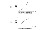
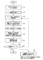
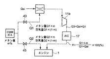
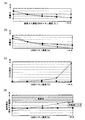
- FIG. 1 is an overall configuration diagram of a fuel gas supply device for a gas engine according to an embodiment of the present invention. It is a characteristic which shows an example of the flow volume and opening degree in the flow valve adjustment means in a gas supply controller, (a) shows a 1st fuel gas adjustment valve, (b) shows a 2nd fuel gas adjustment valve. It is explanatory drawing which shows the inflow state of the fuel gas to a suction port. The control flowchart in a gas supply controller is shown. It is a schematic diagram explaining the relationship between the fuel gas amounts Q1, Q2, and Q3 and the supply gas concentration H in the supply pipe. It is a graph which shows contrast with a comparative example, (a) shows flow rate Q1, (b) shows flow rate Q2, (c) shows the ratio state of Q1 / Q2, and (d) is in a supply passage. The gas concentration at is shown.
- an engine (gas engine) 1 includes a cylinder block 3 and a cylinder head 5, and a generator 9 that is directly connected and driven via a flywheel 7 is attached to the engine 1.
- a supercharger 11 including an exhaust turbine 11a and a compressor 11b is provided, and an air supply branch pipe 13 is connected to an air supply inlet of each cylinder head 5, and an air supply outlet of the compressor 11b and each air supply branch are connected.
- An air supply pipe 15 connected to the pipe 13 and a supply air cooler 17 for cooling the air supply flowing through the air supply pipe 15 are provided.
- Each exhaust pipe 19 connected to the exhaust outlet of each cylinder head 5 is connected to an exhaust collecting pipe 21.
- the exhaust collecting pipe 21 is connected to an exhaust turbine 11a, and exhaust gas from an exhaust gas outlet of the exhaust turbine 11a is removed.
- An exhaust outlet pipe 23 for discharging is provided.
- an exhaust bypass pipe 25 is provided which branches from the inlet side of the exhaust turbine 11a of the exhaust collecting pipe 21 to bypass the exhaust turbine 11a and is connected to the exhaust outlet pipe 23 on the outlet side of the exhaust turbine 11a.
- the exhaust bypass pipe 25 is provided with an exhaust bypass valve 27 that changes the passage area.
- a supercharger inlet air passage 29 is provided for introducing air from the outside to the compressor 11 b of the supercharger 11.
- a mixer 31 is installed in the supercharger inlet air passage 29, and the mixer 31 is supercharged.
- a machine side gas supply pipe (supercharger side gas supply passage) 33 is connected.
- the machine-side gas supply pipe 33 and the cylinder-side gas supply pipe (cylinder-side gas supply passage) 37 are branched, and the cylinder-side gas supply pipe 37 is branched for each cylinder along the way to become gas supply branch pipes 39.
- the supply branch pipe 13 is connected.
- the cylinder side gas supply pipe 37 is provided with a gas compressor 41 for compressing the fuel gas flowing through the cylinder side gas supply pipe 37.
- coal mine methane gas (CMM gas), landfill gas (biogas), and the like, and an example in which coal mine methane gas is used is shown in this embodiment.
- This coal mine methane gas (Coal Mine Methane, CMM gas) is composed of a mixture of air and methane gas.
- Coal mine methane gas refers to methane gas that is produced from the coal seam during its mining process, and is generated from the seabed and its surroundings during coal mining. % To 50%.
- the supercharger-side gas supply pipe 33 is provided with a supercharger-side gas amount adjustment valve (first fuel gas adjustment valve) 43 for controlling the fuel gas flow rate Q1 to the supercharger inlet air passage 29.
- Each gas supply branch pipe 39 is provided with a cylinder side gas amount adjustment valve (second fuel gas adjustment valve) 45 for controlling the fuel gas flow rate Q2 ′ flowing through each gas supply branch pipe 39. Then, the fuel gas flow rate Q2 supplied by the cylinder side gas supply pipe 37 is controlled as the sum of the fuel gas flow rate Q2 ′ flowing through each gas supply branch pipe 39 for all the cylinders.
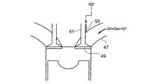
- FIG. 3 shows the inflow state of the fuel gas in the portion A of the air supply branch pipe 13 in FIG.
- the fuel gas pressurized by the supercharger 11 is supplied to the air supply port 47 of FIG. 3 through the air supply branch pipe 13.
- This fuel gas is a mixture of the air Qai guided to the mixer 31 through the supercharger inlet air passage 29 and the fuel gas flow rate Q1 guided to the mixer 31 through the supercharger side gas supply pipe 33.
- a total flow rate Q3 flows.
- the fuel gas flow rate Q2 ′ flowing through each gas supply branch pipe 39 connected to each supply branch pipe 13 is at the sliding portion between the valve shaft 51 of the supply valve 49 and the cylinder head 5 or the sliding portion. It is guided to the air supply port 47 through the formed passage such as the groove 53.
- a supply air temperature sensor 61 for detecting the above is provided. Further, signals from these sensors are input to the gas supply controller 63.
- the gas supply controller 63 includes a fuel gas amount Q1 of the supercharger side gas supply pipe 33 adjusted by the supercharger side gas amount adjustment valve 43 and a cylinder side gas adjusted by the cylinder side gas amount adjustment valve 45.
- the flow rate ratio holding means 65 for holding the flow rate ratio Q1 / Q2 with the fuel gas amount Q2 of the supply pipe 37 at a constant value, and the cylinder side so as to maintain the engine output constant when the gas concentration of the fuel gas changes.
- the second fuel gas adjustment valve control means 67 for adjusting the gas amount adjustment valve 45 to adjust the fuel gas quantity Q2, and the flow rate set after the adjustment of the fuel gas quantity Q2 by the second fuel gas adjustment valve control means 67
- Fuel gas amount Q1 is calculated based on the ratio
- first fuel gas adjustment valve control means 69 is provided for adjusting the opening degree of the supercharger side gas amount adjustment valve 43 from the fuel gas amount Q1.
- the fuel gas from the gas supply pipe 35 is branched in the middle of the gas supply pipe 35. Then, one of the branched fuel gases is introduced into the mixer 31 through the supercharger side gas supply pipe 33, and is mixed with the air from the supercharger inlet air passage 29 in the mixer 31. It is introduced into the compressor 11 b of the feeder 11.
- the air-fuel mixture gas pressurized to a high temperature and a high pressure by the compressor 11b is cooled by the air supply cooler 17 and cooled down, and flows into the air supply branch pipe 13 of each cylinder through the air supply pipe 15.
- the other of the branched fuel gas enters the cylinder side gas supply pipe 37, is compressed by the gas compressor 41, passes through each gas supply branch pipe 39 of each cylinder, enters each supply branch pipe 13, and FIG.
- the air-fuel mixture gas flows into the air supply branch pipe 13 of each cylinder through the air supply pipe 15 and is fed into each cylinder.
- the fuel gas burned in each cylinder of the engine 1 is merged in the exhaust collecting pipe 21 through the exhaust pipe 19 as exhaust gas after combustion, and is supplied to the exhaust turbine 11a of the supercharger 11 to be supplied to the exhaust turbine 11a. Is driven to the outside through the exhaust outlet pipe 23.
- CCM gas coal mine methane gas
- the fuel gas supply device of the gas engine having the above-described configuration a control method when the methane concentration of coal mine methane gas (CMM gas), which is the fuel gas, in the fuel gas supply device of the gas engine having the above-described configuration is described below with reference to FIG. .
- CCM gas methane concentration of coal mine methane gas
- the calorific value of the fuel gas changes in step S2
- the output of the engine 1 changes.
- the power generation output from the generator 9 fluctuates, and the fluctuation value is detected by the rotation speed sensor 55 or the load detector 57.
- step S3 output adjustment is performed to return the generator output to the state before the change with respect to the change in the generator output.
- This output adjustment is broadly adjusted by adjusting the fuel gas amount Q2 of the cylinder side gas supply pipe 37 adjusted by the cylinder side gas amount adjusting valve (second fuel gas adjusting valve) 45 in step S3, and the supercharging in step S7. This is performed by the fuel gas amount Q1 of the supercharger side gas supply pipe 33 adjusted by the machine side gas amount adjustment valve 43.
- step S3 a normal electronic governor function is performed so that the target rotational speed is set based on the detected value of the engine speed from the rotational speed sensor 55, or based on the detected load value from the load detector 57.
- the opening degree of each cylinder side gas amount adjusting valve 45 is controlled so as to obtain the set power generation output. That is, when the gas concentration of the fuel gas increases, the opening degree of each cylinder side gas amount adjustment valve 45 is controlled so as to decrease the fuel gas amount Q2 so as to maintain the engine output constant, and the fuel gas When the gas concentration decreases, the opening degree of each cylinder side gas amount adjusting valve 45 that increases the fuel gas amount Q2 is controlled so as to keep the engine output constant.
- step S4 the fuel gas flow rate Q2 ′ flowing through each gas supply branch pipe 39 is calculated from the valve opening degree of each cylinder side gas amount adjusting valve 45 in step S3. This calculation is based on the characteristic relationship between the flow rate and the valve opening in the second fuel gas regulating valve control means 67 in the gas supply controller 63 as shown in FIG. Then, the fuel gas flow rate Q2 supplied by the cylinder side gas supply tube 37 is calculated as the sum of the fuel gas flow rate Q2 ′ flowing through each gas supply branch pipe 39 for all the cylinders.
- step S5 according to a constant ratio value (for example, a value smaller than 1) set in the flow ratio holding means 65 that holds the flow ratio Q1 / Q2 at a constant value, A fuel gas amount Q1 is calculated.
- a constant ratio value for example, a value smaller than 1
- step S6 the opening degree of the supercharger side gas amount adjusting valve 43 is calculated from the fuel gas amount Q1 of the supercharger side gas supply pipe 33. And in step S7, the opening degree adjustment of the supercharger side gas amount adjustment valve 43 is performed based on the calculated opening degree.
- step S8 whether or not the output of the generator 9 is kept is determined based on the detection value of the rotation speed sensor 55 or the load detector 57. If not, the process returns to step S3 and the steps from the opening degree control of each cylinder side gas amount adjusting valve 45 are repeated.
- step S8 if the output of the generator 9 holds a constant state, the process ends. At the same time, the process proceeds to step S9, and when the power generation output is kept constant, it is determined that the supercharger outlet flow rate Q3 is kept constant, and the exhaust bypass valve 27 is not controlled.
- the exhaust bypass valve 27 is controlled such that when the outside air temperature or pressure changes, the supercharger outlet flow rate Q3 is kept constant in order to avoid changes in the air-fuel ratio and maintain stable combustion.
- the constant control of the supercharger outlet flow rate Q3 is performed based on signals from the supply air pressure sensor 59 and the supply air temperature sensor 61.
- FIG. 6 shows the methane concentration of CMM gas supplied as fuel gas on the horizontal axis, (a) shows the flow rate Q1 on the vertical axis, (b) shows the flow rate Q2 on the vertical axis, and (c) shows the vertical axis.
- the axis shows the ratio of Q1 / Q2, and (d) shows the gas concentration in the supply pipe on the vertical axis.
- the comparative example shows a case where control is performed to keep the flow rate Q1 of the gas supply amount before the supercharger constant, and is shown by the dotted line in FIGS. 6 (a) to 6 (d).
- the flow rate Q1 since the flow rate Q1 is constant, when the methane concentration in the fuel gas becomes high, the flow rate Q2 is decreased to control the engine output constant, but the flow rate Q1 is kept constant.
- the ratio of Q1 / Q2 increases as shown in (c), and as the methane concentration in the flow rate Q1 increases, the methane concentration in the supply pipe increases, as shown in (d).
- the flow rate Q2 when the methane concentration in the fuel gas amount becomes high, the flow rate Q2 is decreased so that the engine output becomes constant (FIG. 6B), and then a constant ratio (FIG. c)), the flow rate Q1 is decreased (FIG. 6A).
- the supply gas concentration H on the downstream side of the compressor 11b is constant as shown in the equation (1) (FIG. 6 (d)).
- the supercharger-side gas supply pipe can be obtained by simple control that only controls the flow rates of the fuel gas quantity Q1 of the supercharger-side gas supply pipe 33 and the fuel gas quantity Q2 of the cylinder-side gas supply pipe 37. It is possible to reliably prevent the concentration of the fuel gas introduced from 33 and introduced into the air supply pipe 15 from being ignited in the air supply pipe to a concentration that causes abnormal combustion such as an explosion. As a result, safety can be improved.
- the fuel gas amount Q2 is increased so as to maintain the engine output constant, and the fuel gas amount Q1 is increased based on the constant flow rate ratio, so that the mixer 31 acts to suppress a decrease in the gas concentration of the mixed fuel gas introduced into the compressor 11b of the supercharger 11 and maintain it at a substantially constant value, and further to maintain the engine output constant. Since the fuel gas amount Q2 is increased and the fuel gas amount Q1 is increased based on the constant flow rate ratio, the fuel gas amount Q2 can be quickly reached.
- the ignition or explosion of the fuel gas in the air supply passage including the supercharger outlet can be surely and easily performed by controlling the fuel gas amount. Therefore, it is suitable for use in a fuel gas supply method and apparatus for a gas engine.
Abstract
ガス供給管35が、過給機側ガス供給管33と、シリンダ側ガス供給管37とに分岐され、それぞれの通路流量を制御する過給機側ガス量調整弁43と、シリンダ側ガス量調整弁45とを備えたガスエンジンにおいて、燃料ガスの濃度変化時に、ガス供給コントローラ63によって、過給機側ガス供給管33の燃料ガス量Q1と、シリンダ側ガス供給管37の燃料ガス量Q2との比率Q1/Qを一定関係を有しつつ、エンジン出力を一定に維持するようにシリンダ側ガス量調整弁45を始めに制御して、次に一定比率に基づく燃料ガス量Q1になるように過給機側ガス量調整弁43を制御することを特徴とする。
Description
本発明は、燃料ガス通路を介して供給される燃料ガスと、空気とを混合して混合ガスを燃焼室に供給して燃焼せしめるガスエンジンの燃料ガス供給方法および装置に関するものである。
従来、ガスエンジンのうち特に小型ガスエンジンにおいては、一般的に過給機上流にて燃料ガスと空気を混合させて燃焼室へ供給する過給機前吸込み方式を採用していた。
このような全量ガスを過給機前吸込み方式で供給する場合、燃料ガスのカロリー変動と共に給気室でのガス濃度も変動し、給気室内ガスの濃度によっては、給気室内で自己着火等の異常燃焼を生じるおそれがあり、給気室内の安全度が燃料ガスカロリーに依存してしまう。
このような全量ガスを過給機前吸込み方式で供給する場合、燃料ガスのカロリー変動と共に給気室でのガス濃度も変動し、給気室内ガスの濃度によっては、給気室内で自己着火等の異常燃焼を生じるおそれがあり、給気室内の安全度が燃料ガスカロリーに依存してしまう。
一方、従来の大型ガスエンジンの多くは、燃料ガスと空気の混合比(空燃比)及びガス投入量を各シリンダにより均一化する必要があるため、各シリンダの直前に設置した燃料ガス調整弁にて燃焼室へ燃料ガスを供給している。この方式を採用することにより、各シリンダに供給される空燃比及びガス投入量が均一化されるとともに、各シリンダにおける仕事が効率化され、さらにまた、シリンダ直前にて燃料ガスと空気とを混合する構成であるため、混合ガス供給路における可燃域を短くすることができ安全性が向上する。
また、上記した2つの方式を組み合わせた技術として、特許文献1(特開2001-132550号公報)の技術が知られており、この技術においては、ガスコンプレッサによる昇圧前の燃料ガスを過給機上流の給気通路に供給する供給手段と、ガスコンプレッサによって昇圧された燃料ガスをシリンダ室への給気通路またはシリンダ内に噴射供給する供給手段とを備え、過給機上流の給気通路に供給する供給手段が、供給作用状態と停止状態とに切換え自在に設けられている。
しかしながら、特許文献1に示された技術においては、ガスコンプレッサによって加圧された燃料ガスをシリンダ内に供給する燃料ガス供給系では、燃料ガスを過給空気圧よりも高圧に圧縮する必要があるが、燃料ガスとして炭鉱メタンガス等の低カロリーガス(発熱量の低いガス)を用いる場合には、低圧で大流量のガスを圧縮するために大型で大容量のガスコンプレッサを必要とする。また、燃料ガスを過給機上流の給気通路に供給する供給系では、給気通路において燃料ガスが可燃下限界以上のガス濃度になり自己着火等の異常燃焼を生じるおそれがある。
そこで、特許文献2(特開2006-2449954号公報)では、燃料ガスの一方を過給機入口空気と混合しこの混合気を過給機に供給すると共に、燃料ガスの他方をシリンダ毎の給気通路内の給気と混合しこの混合気をエンジンの各シリンダに供給するように構成し、過給機側ガス供給通路のガス流量を調整する過給機側ガス量調整弁と各シリンダ側ガス供給通路のガス流量を調整するシリンダ側ガス量調整弁とを設け、過給機側ガス量調整弁の開度を制御して、過給機側ガス供給通路への燃料ガス量を、過給機に供給する混合気中の燃料ガス濃度が可燃下限界ガス濃度以下に保持されるように調整するガス量コントローラを設けた構成を開示している。
これによれば、過給機出口での燃料ガスの自己着火等の異常燃焼の可能性を皆無とするとともに、低カロリーガス(発熱量の低いガス)燃料を用いる場合においてもシリンダ毎の給気通路への燃料ガス圧縮用のガスコンプレッサの動力を低減して該ガスコンプレッサを小型化、小容量化することが可能となる。
この特許文献2と同様の燃料ガスの供給構成が示されたものとして特許文献3(特開2009-144626号公報)も知られている。
この特許文献2と同様の燃料ガスの供給構成が示されたものとして特許文献3(特開2009-144626号公報)も知られている。
上記したように、特許文献2、3によれば、低カロリーガスであっても十分な燃料ガスの供給量を確保でき、また燃料ガス圧縮用のガスコンプレッサを小型化、小容量化することが可能であり、さらに、過給機に供給する混合気中の燃料ガス濃度が可燃下限界ガス濃度以下に保持されるように調整することによって、給気通路において燃料ガスが可燃下限界以上のガス濃度になり自己着火等の異常燃焼を生じないようにしている。
しかし、この自己着火等の異常燃焼の防止を行う制御および構成については具体的には開示されていない。さらに、燃料ガスがカロリー変動する場合でも、燃料ガスの濃度を直接計測する濃度計を用いずに簡単な構成によって、且つ確実に給気通路内で可燃性の燃料ガスが異常燃焼を生じることがない制御方法が望まれている。
しかし、この自己着火等の異常燃焼の防止を行う制御および構成については具体的には開示されていない。さらに、燃料ガスがカロリー変動する場合でも、燃料ガスの濃度を直接計測する濃度計を用いずに簡単な構成によって、且つ確実に給気通路内で可燃性の燃料ガスが異常燃焼を生じることがない制御方法が望まれている。
従って、本発明は前記問題点に鑑み、低カロリーで発熱量が変動しやすい燃料ガスにおいて、燃料ガス量の供給制御によって、確実且つ簡単に過給機出口を含めた給気通路内での燃料ガスの自己着火等の異常燃焼を防止して安全性を確保できるガスエンジンの燃料ガス供給方法および装置を提供することを目的とする。
そこで、本発明はかかる課題を解決するために、低カロリーで変動がある燃料ガスを供給する燃料ガス通路が、過給機の空気入口側に設置されたミキサに接続される過給機側ガス供給通路と、シリンダへの給気通路に接続されるとともに前記燃料ガスを圧縮するガスコンプレッサが介装されたシリンダ側ガス供給通路とに分岐され、前記過給機側ガス供給通路の流量を制御する第1燃料ガス調整弁と、前記シリンダ側ガス供給通路の流量を制御する第2燃料ガス調整弁とを備えたガスエンジンの燃料ガス供給方法において、
前記第1燃料ガス調整弁によって調整される過給機側ガス供給通路の燃料ガス量Q1と、前記第2燃料ガス調整弁によって調整されるシリンダ側ガス供給通路の燃料ガス量Q2との流量比率Q1/Q2を一定値に保持し、燃料ガスのガス濃度が変化した際に、エンジン出力を一定に維持するように前記第2燃料ガス調整弁を調整して前記燃料ガス量Q2を調整し、その後、前記流量比率に基づいて前記燃料ガス量Q1を算出し、該燃料ガス量Q1により前記第1燃料ガス調整弁を調整することを特徴とする。
前記第1燃料ガス調整弁によって調整される過給機側ガス供給通路の燃料ガス量Q1と、前記第2燃料ガス調整弁によって調整されるシリンダ側ガス供給通路の燃料ガス量Q2との流量比率Q1/Q2を一定値に保持し、燃料ガスのガス濃度が変化した際に、エンジン出力を一定に維持するように前記第2燃料ガス調整弁を調整して前記燃料ガス量Q2を調整し、その後、前記流量比率に基づいて前記燃料ガス量Q1を算出し、該燃料ガス量Q1により前記第1燃料ガス調整弁を調整することを特徴とする。
かかる発明によれば、第1燃料ガス調整弁によって調整される過給機側ガス供給通路の燃料ガス量Q1と、第2燃料ガス調整弁によって調整されるシリンダ側ガス供給通路の燃料ガス量Q2との関係を、流量比率Q1/Q2が一定値に保持されるように設定して、燃料ガスのガス濃度が変化した際に、エンジン出力を一定に維持するように、まず第2燃料ガス調整弁を調整して燃料ガス量Q2を調整する。その後、流量比率に基づいて燃料ガス量Q1を算出し、該燃料ガス量Q1より第1燃料ガス調整弁の開度を調整する。
このように、過給機側ガス供給通路の燃料ガス量Q1と、シリンダ側ガス供給通路の燃料ガス量Q2とを、流量比率Q1/Qを一定に制御するとともに、エンジン出力を一定に維持するように第2燃料ガス調整弁を始めに制御して、次に流量比率に基づいて燃料ガス量Q1を制御することによって、過給機側ガス供給通路から導入される燃料ガスの濃度を給気管内で自己着火や引火や爆発等の異常燃焼を生じるような濃度に上昇させることを防止できる。その結果も安全性が向上する。
また、本発明においては、ガス濃度計を設置することなく、燃料ガス量Q1及びQ2を制御することによって、給気管内での自己着火や引火や爆発等の異常燃焼を防止して安全性を確保できるので、制御装置が簡単化されて、システム全体を軽量コンパクトに構成できる。
また、本発明においては、ガス濃度計を設置することなく、燃料ガス量Q1及びQ2を制御することによって、給気管内での自己着火や引火や爆発等の異常燃焼を防止して安全性を確保できるので、制御装置が簡単化されて、システム全体を軽量コンパクトに構成できる。
低カロリーで変動がある燃料ガスは、例えば、炭鉱メタンガス(Coal Mine Methane、CMMガス)や、ランドフィルガス(バイオガス)等のような空気とメタンガスの混合によって成立しているものであり、メタンガス濃度が変化した場合には、その変化に応じて、濃度が高くなればエンジン出力が上昇し、濃度が低下すればエンジン出力は低下する。
このため、メタンガス濃度の変化時にエンジン出力を一定にするためには、メタンガス濃度が高くなったときには、燃料ガス流量を低下させ、メタンガス濃度が下がったときには、燃料ガス流量を増加させるようにしている。
このため、メタンガス濃度の変化時にエンジン出力を一定にするためには、メタンガス濃度が高くなったときには、燃料ガス流量を低下させ、メタンガス濃度が下がったときには、燃料ガス流量を増加させるようにしている。
従って、この燃料ガス流量の増減の際に、シリンダ側ガス供給通路の燃料ガス量Q2と過給機側ガス供給通路から導入される燃料ガス量Q1との関係をどのように設定するかが問題となる。
過給機側ガス供給通路から導入される燃料ガス量Q1を常に一定にする制御をしている場合には、燃料ガスのメタンガス濃度が高まった場合に、過給機側ガス供給通路から導入されるメタンガス成分が増大して、給気管内で自己着火や引火や爆発等の異常燃焼を生じる濃度に達し易くなる危険性を有している。
過給機側ガス供給通路から導入される燃料ガス量Q1を常に一定にする制御をしている場合には、燃料ガスのメタンガス濃度が高まった場合に、過給機側ガス供給通路から導入されるメタンガス成分が増大して、給気管内で自己着火や引火や爆発等の異常燃焼を生じる濃度に達し易くなる危険性を有している。
しかし、本発明においては、過給機側ガス供給通路の燃料ガス量Q1と、シリンダ側ガス供給通路の燃料ガス量Q2とを、流量比率Q1/Q2を一定比率の関係に設定して制御する。さらに、エンジン出力を一定にするように制御するとともに、まず第2燃料ガス調整弁によってQ2から制御することを特徴としている。
従って、メタンガス濃度が高くなったときには、一定出力なるようにシリンダ側ガス供給通路の燃料ガス量Q2を低下させるとともに、一定比率によって、過給機側ガス供給通路の燃料ガス量Q1をも低下させるので、過給機側ガス供給通路から導入されるメタン成分が増大して、給気管内で自己着火や引火や爆発等の異常燃焼を生じる危険性が回避される。
従って、メタンガス濃度が高くなったときには、一定出力なるようにシリンダ側ガス供給通路の燃料ガス量Q2を低下させるとともに、一定比率によって、過給機側ガス供給通路の燃料ガス量Q1をも低下させるので、過給機側ガス供給通路から導入されるメタン成分が増大して、給気管内で自己着火や引火や爆発等の異常燃焼を生じる危険性が回避される。
すなわち、本発明おいて好ましくは、燃料ガスのガス濃度が上昇したとき、前記エンジン出力を一定に維持するように前記燃料ガス量Q2を低下させると共に、前記一定の流量比率に基づいて前記燃料ガス量Q1を低下させて、前記ミキサによって混合されて過給機に導入される混合燃料ガスのガス濃度の上昇を抑えて略一定値に保持するとよい。なお、この前記略一定値に保持されるガス濃度が燃料ガスの空気に対して可燃下限界ガス濃度未満の所定の濃度であるとよい。
なお、燃料ガスのガス濃度が低下したときは、前記エンジン出力を一定に維持するように前記燃料ガス量Q2を増加させると共に、前記一定の流量比率に基づいて前記燃料ガス量Q1を増加させて、前記ミキサによって混合されて過給機に導入される混合燃料ガスのガス濃度の低下を抑え略一定値に保持するとよい。
このように、燃料ガスのガス濃度が低下したときには、前記エンジン出力を一定に維持するように前記燃料ガス量Q2を増加すると共に、前記一定の流量比率に基づいて前記燃料ガス量Q1を増加させるので、一定出力へ迅速に到達できる。
また、前記ガスエンジンは発電用エンジンであり、前記エンジン出力が一定に維持されることによって該ガスエンジンによる発電出力が一定になるように運転されるとよい。
さらに、前記燃料ガスが、発熱量が低くかつ変動し易い炭鉱メタンガスである場合に適する。
さらに、前記燃料ガスが、発熱量が低くかつ変動し易い炭鉱メタンガスである場合に適する。
また、本発明のガスエンジンの燃料ガス供給方法を実施するための供給装置は、低カロリーで変動がある燃料ガスを供給する燃料ガス通路が、過給機の空気入口側に設置されたミキサに接続される過給機側ガス供給通路と、シリンダへの給気通路に接続されるとともに前記燃料ガスを圧縮するガスコンプレッサが介装されたシリンダ側ガス供給通路とに分岐され、前記過給機側ガス供給通路の流量を制御する第1燃料ガス調整弁と、前記シリンダ側ガス供給通路の流量を制御する第2燃料ガス調整弁とを備えたガスエンジンの燃料ガス供給装置において、
前記第1燃料ガス調整弁と前記第2燃料ガス調整弁との開度を制御するガス供給コントローラを備え、該ガス供給コントローラには、前記第1燃料ガス調整弁によって調整される過給機側ガス供給通路の燃料ガス量Q1と、前記第2燃料ガス調整弁によって調整されるシリンダ側ガス供給通路の燃料ガス量Q2との流量比率Q1/Q2を一定値に保持する流量比率保持手段と、燃料ガスのガス濃度が変化した際に、エンジン出力を一定に維持するように前記第2燃料ガス調整弁を調整して前記燃料ガス量Q2を調整する第2燃料ガス調整弁制御手段と、その第2燃料ガス調整弁制御手段による燃料ガス量Q2の調整後に、前記流量比率に基づいて前記燃料ガス量Q1を算出し、該燃料ガス量Q1より前記第1燃料ガス調整弁の開度を調整する第1燃料ガス調整弁制御手段と、を備えることを特徴とする。
前記第1燃料ガス調整弁と前記第2燃料ガス調整弁との開度を制御するガス供給コントローラを備え、該ガス供給コントローラには、前記第1燃料ガス調整弁によって調整される過給機側ガス供給通路の燃料ガス量Q1と、前記第2燃料ガス調整弁によって調整されるシリンダ側ガス供給通路の燃料ガス量Q2との流量比率Q1/Q2を一定値に保持する流量比率保持手段と、燃料ガスのガス濃度が変化した際に、エンジン出力を一定に維持するように前記第2燃料ガス調整弁を調整して前記燃料ガス量Q2を調整する第2燃料ガス調整弁制御手段と、その第2燃料ガス調整弁制御手段による燃料ガス量Q2の調整後に、前記流量比率に基づいて前記燃料ガス量Q1を算出し、該燃料ガス量Q1より前記第1燃料ガス調整弁の開度を調整する第1燃料ガス調整弁制御手段と、を備えることを特徴とする。
かかる発明によれば、ガス供給コントローラの流量比率保持手段によって、第1燃料ガス調整弁によって調整される過給機側ガス供給通路の燃料ガス量Q1と、第2燃料ガス調整弁によって調整されるシリンダ側ガス供給通路の燃料ガス量Q2との関係が、流量比率Q1/Q2の一定値に保持され、第2燃料ガス調整弁制御手段によって、燃料ガスのガス濃度が変化した際に、まずエンジン出力を一定に維持するように、第2燃料ガス調整弁を調整し、その第2燃料ガス調整弁制御手段による燃料ガス量Q2の調整後に、第1燃料ガス調整弁制御手段によって燃料ガス量Q2の調整量と流量比率に基づいて燃料ガス量Q1を算出し、該燃料ガス量Q1より第1燃料ガス調整弁の開度を調整する。
このように、過給機側ガス供給通路の燃料ガス量Q1と、シリンダ側ガス供給通路の燃料ガス量Q2とを、流量比率Q1/Qを一定に制御するとともに、エンジン出力を一定に維持するように第2燃料ガス調整弁を始めに制御して、次に流量比率に基づいて燃料ガス量Q1を制御することによって、過給機側ガス供給通路から導入される燃料ガスの濃度を給気管内で自己着火や引火や爆発等の異常燃焼を生じるような濃度に上昇させることを防止し安全性を向上できる。
以上記載のごとく方法発明および装置発明それぞれにおいて、低カロリーで発熱量が変動しやすい燃料ガスにおいて、燃料ガス量の供給制御によって、確実且つ簡単に過給機出口を含めた給気通路内での燃料ガスの自己着火等の異常燃焼を防止して安全性を確保できる。
すなわち、過給機側ガス供給通路の燃料ガス量Q1と、シリンダ側ガス供給通路の燃料ガス量Q2とを、流量比率Q1/Qを一定に制御するとともに、エンジン出力を一定に維持するように第2燃料ガス調整弁を始めに制御して、次に流量比率に基づいて燃料ガス量Q1を制御することによって、過給機側ガス供給通路から導入される燃料ガスの濃度を給気管内で自己着火や引火や爆発等の異常燃焼を生じるような濃度に上昇させることを防止できる。その結果安全性が向上する。
すなわち、過給機側ガス供給通路の燃料ガス量Q1と、シリンダ側ガス供給通路の燃料ガス量Q2とを、流量比率Q1/Qを一定に制御するとともに、エンジン出力を一定に維持するように第2燃料ガス調整弁を始めに制御して、次に流量比率に基づいて燃料ガス量Q1を制御することによって、過給機側ガス供給通路から導入される燃料ガスの濃度を給気管内で自己着火や引火や爆発等の異常燃焼を生じるような濃度に上昇させることを防止できる。その結果安全性が向上する。
以下、本発明を図に示した実施形態を用いて詳細に説明する。
但し、この実施形態に記載されている構成部品の寸法、材質、形状、その相対配置などは特に特定的な記載がない限り、この発明の範囲をそれのみに限定する趣旨ではなく、単なる説明例にすぎない。
但し、この実施形態に記載されている構成部品の寸法、材質、形状、その相対配置などは特に特定的な記載がない限り、この発明の範囲をそれのみに限定する趣旨ではなく、単なる説明例にすぎない。
図1を参照して、本実施形態のガスエンジンの燃料供給装置の全体構成につき説明する。同図において、エンジン(ガスエンジン)1は、シリンダブロック3とシリンダヘッド5からなり、また、該エンジン1にはフライホイール7を介して直結駆動される発電機9が取り付けられている。
また、排気タービン11a及びコンプレッサ11bからなる過給機11が備えられ、前記各シリンダヘッド5の給気入口に給気枝管13が接続され、前記コンプレッサ11bの給気出口と前記各給気枝管13とを接続する給気管15、および該給気管15を流れる給気を冷却する給気冷却器17が設けられている。
各シリンダヘッド5の排気出口に接続された各排気管19は、排気集合管21に接続され、該排気集合管21は排気タービン11aに接続され、排気タービン11aの排気ガス出口からの排気ガスを排出するための排気出口管23が取りけられている。
各シリンダヘッド5の排気出口に接続された各排気管19は、排気集合管21に接続され、該排気集合管21は排気タービン11aに接続され、排気タービン11aの排気ガス出口からの排気ガスを排出するための排気出口管23が取りけられている。
また、排気集合管21の排気タービン11aの入口側から分岐されて該排気タービン11aをバイパスし、該排気タービン11aの出口側の排気出口管23に接続される排気バイパス管25が設けられている。そして該排気バイパス管25には通路面積を変化せしめる排気バイパス弁27が設けられている。
外部から空気を前記過給機11のコンプレッサ11bに導入するための過給機入口空気通路29が設けられ、過給機入口空気通路29にはミキサ31が設置され、該ミキサ31には過給機側ガス供給管(過給機側ガス供給通路)33が接続されている。
また、低カロリーで変動がある燃料ガスを収容する燃料ガスタンク(図示省略)から燃料ガスが導入されるガス供給管(燃料ガス供給通路)35は、途中で、該ガス供給管35から前記過給機側ガス供給管33とシリンダ側ガス供給管(シリンダ側ガス供給通路)37とに分岐され、さらに、シリンダ側ガス供給管37は途中でシリンダ毎に分岐されガス供給枝管39となって各給気枝管13に接続されている。さらに、シリンダ側ガス供給管37には該シリンダ側ガス供給管37を流れる燃料ガスを圧縮するガスコンプレッサ41が設けられている。
なお、低カロリーで変動がある燃料ガスは、炭鉱メタンガス(CMMガス)や、ランドフィルガス(バイオガス)等であり、本実施形態では炭鉱メタンガスが用いられる例を示す。この炭鉱メタンガス(Coal Mine Methane、CMMガス)は、空気とメタンガスの混合によって構成されている。炭鉱メタンガスとは、石炭層中にはその生成過程で生じたメタンガスが含有されており、石炭採掘時に炭層およびその周辺から湧き出すメタンガスのことをいい、一般的に炭鉱メタンガス濃度の変動幅は15%~50%である。
過給機側ガス供給管33には過給機入口空気通路29への燃料ガス流量Q1を制御する過給機側ガス量調整弁(第1燃料ガス調整弁)43が設けられている。また、各ガス供給枝管39には該各ガス供給枝管39を流れる燃料ガス流量Q2'を制御するシリンダ側ガス量調整弁(第2燃料ガス調整弁)45が設けられている。そして、各ガス供給枝管39を流れる燃料ガス流量Q2'の全気筒数分の合計としてシリンダ側ガス供給管37によって供給される燃料ガス流量Q2が制御される。
また、図1の給気枝管13のA部分における燃料ガスの流入状態を図3に示す。
図3の給気ポート47には、給気枝管13を通って、過給機11で加圧された燃料ガスが供給される。この燃料ガスは、過給機入口空気通路29を通ってミキサ31に導かれる空気Qaiと過給機側ガス供給管33を通ってミキサ31に導かれる燃料ガス流量Q1とが混合されたもので合計流量Q3が流入する。
一方、各給気枝管13に接続された各ガス供給枝管39を流れる燃料ガス流量Q2'は、給気弁49の弁軸51とシリンダヘッド5との摺動部、または摺動部に形成された溝53等の通路を通って給気ポート47に導かれるようになっている。
図3の給気ポート47には、給気枝管13を通って、過給機11で加圧された燃料ガスが供給される。この燃料ガスは、過給機入口空気通路29を通ってミキサ31に導かれる空気Qaiと過給機側ガス供給管33を通ってミキサ31に導かれる燃料ガス流量Q1とが混合されたもので合計流量Q3が流入する。
一方、各給気枝管13に接続された各ガス供給枝管39を流れる燃料ガス流量Q2'は、給気弁49の弁軸51とシリンダヘッド5との摺動部、または摺動部に形成された溝53等の通路を通って給気ポート47に導かれるようになっている。
エンジン回転数を検出する回転数センサ55、発電機9の負荷つまりエンジン負荷を検出する負荷検出器57、給気管15における給気圧力を検出する給気圧力センサ59、給気管15における給気温度を検出する給気温度センサ61がそれぞれ設けられている。さらに、これらセンサからの信号は、ガス供給コントローラ63に入力されている。
このガス供給コントローラ63には、過給機側ガス量調整弁43によって調整される過給機側ガス供給管33の燃料ガス量Q1と、シリンダ側ガス量調整弁45によって調整されるシリンダ側ガス供給管37の燃料ガス量Q2との流量比率Q1/Q2を一定値に保持する流量比率保持手段65と、燃料ガスのガス濃度が変化した際に、エンジン出力を一定に維持するようにシリンダ側ガス量調整弁45を調整して燃料ガス量Q2を調整する第2燃料ガス調整弁制御手段67と、その第2燃料ガス調整弁制御手段67による燃料ガス量Q2の調整後に、設定された流量比率に基づいて燃料ガス量Q1を算出し、該燃料ガス量Q1より過給機側ガス量調整弁43の開度を調整する第1燃料ガス調整弁制御手段69と、を備えている。
エンジン1の運転時において、ガス供給管35からの燃料ガスは該ガス供給管35の途中で分岐される。そして分岐された燃料ガスの一方は過給機側ガス供給管33を通ってミキサ31に導入され、該ミキサ31において過給機入口空気通路29からの空気と混合されこの混合気燃料ガスは過給機11のコンプレッサ11bに導入される。
そして、該コンプレッサ11bで高温、高圧に加圧された混合気燃料ガスは給気冷却器17で冷却されて降温し、給気管15を通って各シリンダの給気枝管13内に流入する。
そして、該コンプレッサ11bで高温、高圧に加圧された混合気燃料ガスは給気冷却器17で冷却されて降温し、給気管15を通って各シリンダの給気枝管13内に流入する。
また、分岐された燃料ガスの他方はシリンダ側ガス供給管37に入り、ガスコンプレッサ41で圧縮されて、各シリンダの各ガス供給枝管39を通り、各給気枝管13に入り、図3のように給気ポート47内で、給気管15を通って各シリンダの給気枝管13内に流入した混合気燃料ガスに混入して、各シリンダ内に送り込まれる。
そして、エンジン1の各シリンダ内で燃焼した燃料ガスは、燃焼後に排気ガスとして排気管19を通って排気集合管21で合流され、過給機11の排気タービン11aに供給されて該排気タービン11aを駆動した後、排気出口管23を通って外部に排出される。
次に、前記した構成を有するガスエンジンの燃料ガスの供給装置において、燃料ガスである炭鉱メタンガス(CMMガス)のメタン濃度が変化した際の制御方法について、図4を参照して以下に説明する。
まず、ステップS1で、炭鉱メタンガス(CMMガス)のメタン濃度が変化すると、ステップS2で、燃料ガスの発熱カロリーが変動するため、エンジン1の出力が変動する。それに伴い、発電機9からの発電出力が変動し、その変動値を回転数センサ55、または負荷検出器57によって検出する。
まず、ステップS1で、炭鉱メタンガス(CMMガス)のメタン濃度が変化すると、ステップS2で、燃料ガスの発熱カロリーが変動するため、エンジン1の出力が変動する。それに伴い、発電機9からの発電出力が変動し、その変動値を回転数センサ55、または負荷検出器57によって検出する。
そして、ステップS3で、この発電機出力変化に対して、発電機出力を変化前の状態に戻すように出力調整を行う。この出力調整は、大きく見てステップS3のシリンダ側ガス量調整弁(第2燃料ガス調整弁)45によって調整されるシリンダ側ガス供給管37の燃料ガス量Q2の調整と、ステップS7の過給機側ガス量調整弁43によって調整される過給機側ガス供給管33の燃料ガス量Q1によって行われる。
ステップS3では、通常の電子ガバナー機能を行い、回転数センサ55からのエンジン回転数の検出値に基づき設定された目標回転数となるように、または、負荷検出器57からの負荷検出値に基づき設定された発電出力になるよう各シリンダ側ガス量調整弁45の開度を制御する。
すなわち、燃料ガスのガス濃度が上昇したときは、エンジン出力を一定に維持するように燃料ガス量Q2を低下するように各シリンダ側ガス量調整弁45の開度を制御し、また、燃料ガスのガス濃度が低下したときは、エンジン出力を一定に維持するように燃料ガス量Q2を増加する各シリンダ側ガス量調整弁45の開度を制御する。
すなわち、燃料ガスのガス濃度が上昇したときは、エンジン出力を一定に維持するように燃料ガス量Q2を低下するように各シリンダ側ガス量調整弁45の開度を制御し、また、燃料ガスのガス濃度が低下したときは、エンジン出力を一定に維持するように燃料ガス量Q2を増加する各シリンダ側ガス量調整弁45の開度を制御する。
次に、ステップS4で、ステップS3の各シリンダ側ガス量調整弁45の弁開度から各ガス供給枝管39を流れる燃料ガス流量Q2'を算出する。この算出に際しては、図2(b)に示すようなガス供給コントローラ63内の第2燃料ガス調整弁制御手段67における流量と弁開度との特性関係を基に算出する。そして、各ガス供給枝管39を流れる燃料ガス流量Q2'の全気筒数分の合計としてシリンダ側ガス供給管37によって供給される燃料ガス流量Q2が算出される。
次に、ステップS5で、流量比率Q1/Q2を一定値に保持する流量比率保持手段65に設定されている一定比率値(例えば、1より小さい値)に従って、過給機側ガス供給管33の燃料ガス量Q1を算出する。
次にステップS6で、過給機側ガス供給管33の燃料ガス量Q1より、過給機側ガス量調整弁43の開度を算出する。そして、ステップS7では、その算出開度に基づいて過給機側ガス量調整弁43の開度調整を行う。
次に、ステップS8で、発電機9の出力がキープされたか否かを回転数センサ55、または負荷検出器57の検出値に基づいて判定する。保持されていない場合には、ステップS3に戻って、再度、各シリンダ側ガス量調整弁45の開度制御からのステップを繰り返す。
そして、ステップS8で、発電機9の出力が一定状態を保持している場合には終了する。また同時に、ステップS9に進み、発電出力が一定状態を保持している場合には過給機出口流量Q3は一定に保持されていると判定し、排気バイパス弁27の制御は行わない。この排気バイパス弁27の制御は、外気温度や圧力が変化した場合には、空燃比の変化を回避して安定燃焼を維持するために過給機出口流量Q3を一定にするように制御する。この過給機出口流量Q3の一定制御は、給気圧力センサ59および給気温度センサ61からの信号に基づいて行われる。
燃料ガス量Q1、Q2、Q3の関係を基に、ミキサ31からコンプレッサ11b、さらにコンプレッサ11bの給気出口から各給気枝管13と接続する給気管15内の給気ガス濃度Hについて、図5の模式図を参照して説明する。
過給機側ガス供給管33からの燃料ガス量Q1において、メタン濃度をm%とすると、メタン量はQ1×m、空気量はQ1×(1-m)となる。同様に、シリンダ側ガス供給管37からの燃料ガス量Q2において、メタン濃度をm%とすると、メタン量はQ2×m、空気量はQ2×(1-m)となる。
コンプレッサ11bの下流側の流量Q3は、Q3=Qai+Q1となる。また、このコンプレッサ11bの下流側の給気ガス濃度Hは、H=(Q1×m)/(Q1+Qai)と表せる。
過給機側ガス供給管33からの燃料ガス量Q1において、メタン濃度をm%とすると、メタン量はQ1×m、空気量はQ1×(1-m)となる。同様に、シリンダ側ガス供給管37からの燃料ガス量Q2において、メタン濃度をm%とすると、メタン量はQ2×m、空気量はQ2×(1-m)となる。
コンプレッサ11bの下流側の流量Q3は、Q3=Qai+Q1となる。また、このコンプレッサ11bの下流側の給気ガス濃度Hは、H=(Q1×m)/(Q1+Qai)と表せる。
ここで、発電機9の発電出力一定(負荷一定)の条件、つまり、メタン量に基づくカロリー量が一定であることにより、(Q1+Q2)×m=一定=K1となる(メタン濃度変化に対して効率(出力)の変化は非常に小さいので一定とする)。
さらに、コンプレッサ11bの出口ガス量が一定である場合には、Q3=Qai+Q1=一定=K2となる。
また、本発明の特徴事項である、流量比率Q1/Q2=一定=K3となる。
これら、K1、K2、K3の条件を基に、このコンプレッサ11bの下流側の給気ガス濃度HのH=(Q1×m)/(Q1+Qai)の式を書き換えると下記(1)のようになる。
さらに、コンプレッサ11bの出口ガス量が一定である場合には、Q3=Qai+Q1=一定=K2となる。
また、本発明の特徴事項である、流量比率Q1/Q2=一定=K3となる。
これら、K1、K2、K3の条件を基に、このコンプレッサ11bの下流側の給気ガス濃度HのH=(Q1×m)/(Q1+Qai)の式を書き換えると下記(1)のようになる。
H=(Q1×m)/(Q1+Qai)
=(Q1×m)/(Q1+Q3-Q1)
=(Q1/Q3)×m
=(Q1×m)/Q3
=(K1/(1+K3))×1/K2 …(1)
となる。
=(Q1×m)/(Q1+Q3-Q1)
=(Q1/Q3)×m
=(Q1×m)/Q3
=(K1/(1+K3))×1/K2 …(1)
となる。
従って、コンプレッサ11bの下流側の給気ガス濃度Hは一定となることが示される。さらに、図6を参照して、確認試験結果を説明する。
図6は、燃料ガスとして供給されるCMMガスのメタン濃度を横軸に示し、(a)は縦軸に流量Q1を示し、(b)は縦軸に流量Q2を示し、(c)は縦軸にQ1/Q2の比率を示し、(d)は縦軸に給気管内でのガス濃度を示す。
図6は、燃料ガスとして供給されるCMMガスのメタン濃度を横軸に示し、(a)は縦軸に流量Q1を示し、(b)は縦軸に流量Q2を示し、(c)は縦軸にQ1/Q2の比率を示し、(d)は縦軸に給気管内でのガス濃度を示す。
なお、比較例は、過給機前ガス供給量の流量Q1を一定にする制御をした場合を示し、図6(a)~(d)中点線で示す。この比較例の場合には、流量Q1が一定のため、燃料ガス中のメタン濃度が高くなった場合に、エンジン出力一定の制御を行うために流量Q2は低下させるが、流量Q1は一定状態に維持されるため、Q1/Q2の比率は(c)のように大きくなるとともに、流量Q1中のメタン濃度が上昇することによって、給気管内のメタン濃度が上昇し、(d)に示されるように、メタンが自己着火を生じて爆発等の危険領域まで濃度が上昇する危険性がある。
本実施形態では、燃料ガス量中のメタン濃度が高くなった場合には、流量Q2をエンジン出力が一定になるように減少させ(図6(b))、その後に、一定比率(図6(c))に応じて流量Q1を減少させる(図6(a))。
このようにQ1/Q2の一定比率、出力一定制御の基では、式(1)で示したように、コンプレッサ11bの下流側の給気ガス濃度Hは一定となり(図6(d))、給気管内のメタン濃度が上昇しメタンが自己着火して爆発等の危険領域への上昇が確実に防止される。
このようにQ1/Q2の一定比率、出力一定制御の基では、式(1)で示したように、コンプレッサ11bの下流側の給気ガス濃度Hは一定となり(図6(d))、給気管内のメタン濃度が上昇しメタンが自己着火して爆発等の危険領域への上昇が確実に防止される。
このように、過給機側ガス供給管33の燃料ガス量Q1と、シリンダ側ガス供給管37の燃料ガス量Q2との流量を制御するだけの簡単な制御によって、過給機側ガス供給管33から導入されて給気管15内に導かれた燃料ガスの濃度を給気管内で着火して、爆発等の異常燃焼を生じるような濃度に上昇させることを確実に防止できる。その結果安全性を向上できる。
なお、燃料ガスのガス濃度が逆に低下したときには、エンジン出力を一定に維持するように燃料ガス量Q2を増加すると共に、前記一定の流量比率に基づいて燃料ガス量Q1を増加させて、ミキサ31によって混合されて過給機11のコンプレッサ11bに導入される混合燃料ガスのガス濃度の低下を抑え略一定値に保持するように作用するが、さらに、エンジン出力を一定に維持するように前記燃料ガス量Q2を増加すると共に、前記一定の流量比率に基づいて前記燃料ガス量Q1を増加させるので、一定出力へ迅速に到達できる作用も有する。
本発明によれば、低カロリーで発熱量が変動しやすい燃料ガスにおいて、燃料ガス量の制御によって、確実且つ簡単に過給機出口を含めた給気通路内での燃料ガスの着火や爆発等の異常燃焼を防止して安全性を確保できるので、ガスエンジンの燃料ガス供給方法および装置に用いるのに適している。
Claims (7)
- 低カロリーで変動がある燃料ガスを供給する燃料ガス通路が、過給機の空気入口側に設置されたミキサに接続される過給機側ガス供給通路と、シリンダへの給気通路に接続されるとともに前記燃料ガスを圧縮するガスコンプレッサが介装されたシリンダ側ガス供給通路とに分岐され、
前記過給機側ガス供給通路の流量を制御する第1燃料ガス調整弁と、前記シリンダ側ガス供給通路の流量を制御する第2燃料ガス調整弁とを備えたガスエンジンの燃料ガス供給方法において、
前記第1燃料ガス調整弁によって調整される過給機供給通路の燃料ガス量Q1と、前記第2燃料ガス調整弁によって調整されるシリンダ側ガス供給通路の燃料ガス量Q2との流量比率Q1/Q2を一定値に保持し、
燃料ガスのガス濃度が変化した際に、エンジン出力を一定に維持するように前記第2燃料ガス調整弁を調整して前記燃料ガス量Q2を調整し、
その後、前記流量比率に基づいて前記燃料ガス量Q1を算出し、該燃料ガス量Q1により前記第1燃料ガス調整弁を調整することを特徴とするガスエンジンの燃料ガス供給方法。 - 燃料ガスのガス濃度が上昇したとき、前記エンジン出力を一定に維持するように前記燃料ガス量Q2を低下させると共に、前記一定の流量比率に基づいて前記燃料ガス量Q1を低下させて、前記ミキサによって混合されて過給機に導入される混合燃料ガスのガス濃度の上昇を抑えて略一定値に保持することを特徴とする請求項1記載のガスエンジンの燃料ガス供給方法。
- 燃料ガスのガス濃度が低下したとき、前記エンジン出力を一定に維持するように前記燃料ガス量Q2を増加させると共に、前記一定の流量比率に基づいて前記燃料ガス量Q1を増加させて、前記ミキサによって混合されて過給機に導入される混合燃料ガスのガス濃度の低下を抑え略一定値に保持することを特徴とする請求項1記載のガスエンジンの燃料ガス供給方法。
- 前記略一定値に保持されるガス濃度が燃料ガスの空気に対して可燃下限界ガス濃度未満の所定の濃度であることを特徴とする請求項2または3に記載のガスエンジンの燃料ガス供給方法。
- 前記ガスエンジンは発電用エンジンであり、前記エンジン出力が一定に維持されることによって該ガスエンジンによる発電出力が一定になるように運転されることを特徴とする請求項1乃至4のいずれか1項に記載のガスエンジンの燃料ガス供給方法。
- 前記燃料ガスが、発熱量が低くかつ変動し易い炭鉱メタンガスであることを特徴とする請求項1乃至5のいずれか1項に記載のガスエンジンの燃料ガス供給方法。
- 低カロリーで変動がある燃料ガスを供給する燃料ガス通路が、過給機の空気入口側に設置されたミキサに接続される過給機側ガス供給通路と、シリンダへの給気通路に接続されるとともに前記燃料ガスを圧縮するガスコンプレッサが介装されたシリンダ側ガス供給通路とに分岐され、
前記過給機側ガス供給通路の流量を制御する第1燃料ガス調整弁と、前記シリンダ側ガス供給通路の流量を制御する第2燃料ガス調整弁とを備えたガスエンジンの燃料ガス供給装置において、
前記第1燃料ガス調整弁と前記第2燃料ガス調整弁との開度を制御するガス供給コントローラを備え、該ガス供給コントローラには、
前記第1燃料ガス調整弁によって調整される過給機供給通路の燃料ガス量Q1と、前記第2燃料ガス調整弁によって調整されるシリンダ側ガス供給通路の燃料ガス量Q2との流量比率Q1/Q2を一定値に保持する流量比率保持手段と、
燃料ガスのガス濃度が変化した際に、エンジン出力を一定に維持するように前記第2燃料ガス調整弁を調整して前記燃料ガス量Q2を調整する第2燃料ガス調整弁制御手段と、
その第2燃料ガス調整弁制御手段による燃料ガス量Q2の調整後に、前記流量比率に基づいて前記燃料ガス量Q1を算出し、該燃料ガス量Q1より前記第1燃料ガス調整弁の開度を調整する第1燃料ガス調整弁制御手段と、を備えることを特徴とするガスエンジンの燃料ガス供給装置。
Priority Applications (4)
| Application Number | Priority Date | Filing Date | Title |
|---|---|---|---|
| CN201180050750.4A CN103299060B (zh) | 2011-01-31 | 2011-08-22 | 燃气发动机的燃料气体供给方法及装置 |
| US13/881,210 US9828947B2 (en) | 2011-01-31 | 2011-08-22 | Fuel gas supply method and supply unit for gas engine |
| KR1020137011044A KR101418226B1 (ko) | 2011-01-31 | 2011-08-22 | 가스 엔진의 연료 가스 공급 방법 및 장치 |
| EP11857666.9A EP2620629B1 (en) | 2011-01-31 | 2011-08-22 | Fuel gas supply method and device for gas engine |
Applications Claiming Priority (2)
| Application Number | Priority Date | Filing Date | Title |
|---|---|---|---|
| JP2011-018439 | 2011-01-31 | ||
| JP2011018439A JP5308466B2 (ja) | 2011-01-31 | 2011-01-31 | ガスエンジンの燃料ガス供給方法および装置 |
Publications (1)
| Publication Number | Publication Date |
|---|---|
| WO2012105076A1 true WO2012105076A1 (ja) | 2012-08-09 |
Family
ID=46602313
Family Applications (1)
| Application Number | Title | Priority Date | Filing Date |
|---|---|---|---|
| PCT/JP2011/068860 WO2012105076A1 (ja) | 2011-01-31 | 2011-08-22 | ガスエンジンの燃料ガス供給方法および装置 |
Country Status (6)
| Country | Link |
|---|---|
| US (1) | US9828947B2 (ja) |
| EP (1) | EP2620629B1 (ja) |
| JP (1) | JP5308466B2 (ja) |
| KR (1) | KR101418226B1 (ja) |
| CN (1) | CN103299060B (ja) |
| WO (1) | WO2012105076A1 (ja) |
Cited By (1)
| Publication number | Priority date | Publication date | Assignee | Title |
|---|---|---|---|---|
| RU2790746C2 (ru) * | 2019-02-06 | 2023-02-28 | Ман Энерджи Солюшнз Се | Способ эксплуатации двигателя внутреннего сгорания, а также указанный двигатель |
Families Citing this family (15)
| Publication number | Priority date | Publication date | Assignee | Title |
|---|---|---|---|---|
| JP4841690B2 (ja) * | 2010-03-17 | 2011-12-21 | 川崎重工業株式会社 | エンジン発電装置 |
| JP5314637B2 (ja) * | 2010-05-31 | 2013-10-16 | 三菱重工業株式会社 | ガスエンジン |
| JP5308466B2 (ja) * | 2011-01-31 | 2013-10-09 | 三菱重工業株式会社 | ガスエンジンの燃料ガス供給方法および装置 |
| JP5314719B2 (ja) * | 2011-02-28 | 2013-10-16 | 三菱重工業株式会社 | ガスエンジンの給気装置 |
| JP6128975B2 (ja) * | 2013-06-11 | 2017-05-17 | ヤンマー株式会社 | ガスエンジン |
| JP6134587B2 (ja) * | 2013-06-11 | 2017-05-24 | ヤンマー株式会社 | ガスエンジン |
| CH708276A1 (de) * | 2013-07-04 | 2015-01-15 | Liebherr Machines Bulle Sa | Gasmotor. |
| US10378549B2 (en) | 2014-10-17 | 2019-08-13 | Kohler Co. | Dual compressor turbocharger |
| US9556792B2 (en) | 2014-10-17 | 2017-01-31 | Kohler, Co. | Dual compressor turbocharger |
| JP6047217B1 (ja) * | 2015-11-10 | 2016-12-21 | 川崎重工業株式会社 | ガスエンジン駆動システム |
| CN108930597B (zh) * | 2018-07-02 | 2021-03-19 | 武汉理工大学 | 基于快速控制原型的船用中速双燃料发动机控制方法和系统 |
| CN109723537B (zh) * | 2019-01-09 | 2022-05-06 | 陕西柴油机重工有限公司 | 低热值燃气高效增压喷射稀薄燃烧综合控制系统及方法 |
| DE102019102887A1 (de) * | 2019-02-06 | 2020-08-06 | Man Energy Solutions Se | Verfahren zum Betreiben eines Gasmotors oder eines in einem Gaskraftstoffbetriebsmodus betriebenen Dual-Fuel-Motors sowie entsprechender Motor |
| CN111425311B (zh) * | 2020-04-03 | 2022-06-07 | 潍柴动力股份有限公司 | 发动机燃气进气量的调节方法及装置、发动机装置 |
| CN112459929B (zh) * | 2020-12-14 | 2022-03-18 | 湖南省力宇燃气动力有限公司 | 低浓瓦斯发动机供气系统 |
Citations (6)
| Publication number | Priority date | Publication date | Assignee | Title |
|---|---|---|---|---|
| JP2001132550A (ja) | 1999-11-01 | 2001-05-15 | Osaka Gas Co Ltd | ガス燃料エンジン |
| JP2003278605A (ja) * | 2002-03-25 | 2003-10-02 | Shinko Electric Co Ltd | ガスエンジンとその運転方法 |
| JP2004211674A (ja) * | 2003-01-09 | 2004-07-29 | Sanyo Electric Co Ltd | ガスエンジン駆動装置 |
| JP2006009603A (ja) * | 2004-06-23 | 2006-01-12 | Aisin Seiki Co Ltd | ガスエンジン装置 |
| JP2006249954A (ja) | 2005-03-08 | 2006-09-21 | Mitsubishi Heavy Ind Ltd | ガスエンジンのガス供給装置及び運転方法 |
| JP2009144626A (ja) | 2007-12-14 | 2009-07-02 | Mitsubishi Heavy Ind Ltd | ガスエンジンシステムの制御方法及び該システム |
Family Cites Families (19)
| Publication number | Priority date | Publication date | Assignee | Title |
|---|---|---|---|---|
| JP2544817Y2 (ja) * | 1991-08-02 | 1997-08-20 | 本田技研工業株式会社 | 内燃エンジンの蒸発燃料制御装置 |
| US5622053A (en) * | 1994-09-30 | 1997-04-22 | Cooper Cameron Corporation | Turbocharged natural gas engine control system |
| JP4392180B2 (ja) | 2003-03-25 | 2009-12-24 | 大阪瓦斯株式会社 | エンジン |
| JP4319481B2 (ja) | 2003-08-07 | 2009-08-26 | 新潟原動機株式会社 | 希薄燃焼ガスエンジンの燃料ガス供給、給気装置 |
| DE102004043934A1 (de) * | 2004-09-11 | 2006-03-30 | Daimlerchrysler Ag | Verfahren zum Betrieb einer Brennkraftmaschine |
| JP4499643B2 (ja) | 2005-09-30 | 2010-07-07 | 日立オートモティブシステムズ株式会社 | 多段燃料噴射式内燃機関 |
| US7412966B2 (en) | 2005-11-30 | 2008-08-19 | Ford Global Technologies, Llc | Engine output control system and method |
| US7228849B1 (en) * | 2006-09-29 | 2007-06-12 | Delphi Technologies, Inc. | Conical concave cap pressure relief valve |
| JP4739166B2 (ja) * | 2006-10-24 | 2011-08-03 | 本田技研工業株式会社 | ガスセンサ |
| JP4660500B2 (ja) | 2007-03-30 | 2011-03-30 | 大阪瓦斯株式会社 | 内燃機関の燃料供給機構 |
| JP2009062936A (ja) | 2007-09-07 | 2009-03-26 | Toho Gas Co Ltd | 発電システム |
| JP4616878B2 (ja) * | 2007-12-14 | 2011-01-19 | 三菱重工業株式会社 | ガスエンジンシステムの制御方法及び該システム |
| AT506472B1 (de) | 2008-02-18 | 2011-01-15 | Ge Jenbacher Gmbh & Co Ohg | Brennkraftmaschine |
| US8288880B2 (en) * | 2009-04-21 | 2012-10-16 | Gen-Tech Llc | Power generator system |
| JP5314637B2 (ja) * | 2010-05-31 | 2013-10-16 | 三菱重工業株式会社 | ガスエンジン |
| JP5211115B2 (ja) * | 2010-06-28 | 2013-06-12 | 三菱重工業株式会社 | ガスエンジンの給気冷却器のドレン装置 |
| JP5449062B2 (ja) * | 2010-07-02 | 2014-03-19 | 三菱重工業株式会社 | 排ガスタービン過給機のシールエア供給装置 |
| JP5308466B2 (ja) * | 2011-01-31 | 2013-10-09 | 三菱重工業株式会社 | ガスエンジンの燃料ガス供給方法および装置 |
| JP5314719B2 (ja) * | 2011-02-28 | 2013-10-16 | 三菱重工業株式会社 | ガスエンジンの給気装置 |
-
2011
- 2011-01-31 JP JP2011018439A patent/JP5308466B2/ja active Active
- 2011-08-22 WO PCT/JP2011/068860 patent/WO2012105076A1/ja active Application Filing
- 2011-08-22 KR KR1020137011044A patent/KR101418226B1/ko active IP Right Grant
- 2011-08-22 EP EP11857666.9A patent/EP2620629B1/en active Active
- 2011-08-22 CN CN201180050750.4A patent/CN103299060B/zh active Active
- 2011-08-22 US US13/881,210 patent/US9828947B2/en active Active
Patent Citations (6)
| Publication number | Priority date | Publication date | Assignee | Title |
|---|---|---|---|---|
| JP2001132550A (ja) | 1999-11-01 | 2001-05-15 | Osaka Gas Co Ltd | ガス燃料エンジン |
| JP2003278605A (ja) * | 2002-03-25 | 2003-10-02 | Shinko Electric Co Ltd | ガスエンジンとその運転方法 |
| JP2004211674A (ja) * | 2003-01-09 | 2004-07-29 | Sanyo Electric Co Ltd | ガスエンジン駆動装置 |
| JP2006009603A (ja) * | 2004-06-23 | 2006-01-12 | Aisin Seiki Co Ltd | ガスエンジン装置 |
| JP2006249954A (ja) | 2005-03-08 | 2006-09-21 | Mitsubishi Heavy Ind Ltd | ガスエンジンのガス供給装置及び運転方法 |
| JP2009144626A (ja) | 2007-12-14 | 2009-07-02 | Mitsubishi Heavy Ind Ltd | ガスエンジンシステムの制御方法及び該システム |
Cited By (1)
| Publication number | Priority date | Publication date | Assignee | Title |
|---|---|---|---|---|
| RU2790746C2 (ru) * | 2019-02-06 | 2023-02-28 | Ман Энерджи Солюшнз Се | Способ эксплуатации двигателя внутреннего сгорания, а также указанный двигатель |
Also Published As
| Publication number | Publication date |
|---|---|
| EP2620629B1 (en) | 2019-11-06 |
| KR20130058760A (ko) | 2013-06-04 |
| CN103299060B (zh) | 2015-10-07 |
| EP2620629A1 (en) | 2013-07-31 |
| EP2620629A4 (en) | 2017-08-23 |
| US9828947B2 (en) | 2017-11-28 |
| JP2012159017A (ja) | 2012-08-23 |
| US20130220278A1 (en) | 2013-08-29 |
| CN103299060A (zh) | 2013-09-11 |
| KR101418226B1 (ko) | 2014-07-09 |
| JP5308466B2 (ja) | 2013-10-09 |
Similar Documents
| Publication | Publication Date | Title |
|---|---|---|
| JP5308466B2 (ja) | ガスエンジンの燃料ガス供給方法および装置 | |
| JP4563443B2 (ja) | ガスエンジンシステムの制御方法及び該システム | |
| KR101140003B1 (ko) | 가스 엔진 시스템의 제어 방법 및 그 시스템 | |
| JP4247191B2 (ja) | ガスエンジンのガス供給装置及び運転方法 | |
| US9086022B2 (en) | Gas engine | |
| JP5073039B2 (ja) | ガスエンジンのガス供給装置及び該ガス供給装置をそなえたガスエンジン | |
| JP4865241B2 (ja) | ガスエンジンのガス供給装置及び該ガス供給装置をそなえたガスエンジン | |
| JP2005054613A (ja) | 希薄燃焼ガスエンジンの燃料ガス供給、給気方法および燃料ガス供給、給気装置 | |
| JP4452092B2 (ja) | ガスエンジンの燃焼制御方法及びその装置 | |
| EP3583307B1 (en) | Fuel blending system and method |
Legal Events
| Date | Code | Title | Description |
|---|---|---|---|
| 121 | Ep: the epo has been informed by wipo that ep was designated in this application |
Ref document number: 11857666 Country of ref document: EP Kind code of ref document: A1 |
|
| WWE | Wipo information: entry into national phase |
Ref document number: 13881210 Country of ref document: US |
|
| ENP | Entry into the national phase |
Ref document number: 20137011044 Country of ref document: KR Kind code of ref document: A |
|
| NENP | Non-entry into the national phase |
Ref country code: DE |