WO2012095970A1 - ハイブリッド車両の制御装置 - Google Patents
ハイブリッド車両の制御装置 Download PDFInfo
- Publication number
- WO2012095970A1 WO2012095970A1 PCT/JP2011/050378 JP2011050378W WO2012095970A1 WO 2012095970 A1 WO2012095970 A1 WO 2012095970A1 JP 2011050378 W JP2011050378 W JP 2011050378W WO 2012095970 A1 WO2012095970 A1 WO 2012095970A1
- Authority
- WO
- WIPO (PCT)
- Prior art keywords
- clutch
- engine
- torque
- control
- automatic transmission
- Prior art date
Links
Images


Classifications
-
- B—PERFORMING OPERATIONS; TRANSPORTING
- B60—VEHICLES IN GENERAL
- B60W—CONJOINT CONTROL OF VEHICLE SUB-UNITS OF DIFFERENT TYPE OR DIFFERENT FUNCTION; CONTROL SYSTEMS SPECIALLY ADAPTED FOR HYBRID VEHICLES; ROAD VEHICLE DRIVE CONTROL SYSTEMS FOR PURPOSES NOT RELATED TO THE CONTROL OF A PARTICULAR SUB-UNIT
- B60W20/00—Control systems specially adapted for hybrid vehicles
- B60W20/10—Controlling the power contribution of each of the prime movers to meet required power demand
-
- B—PERFORMING OPERATIONS; TRANSPORTING
- B60—VEHICLES IN GENERAL
- B60K—ARRANGEMENT OR MOUNTING OF PROPULSION UNITS OR OF TRANSMISSIONS IN VEHICLES; ARRANGEMENT OR MOUNTING OF PLURAL DIVERSE PRIME-MOVERS IN VEHICLES; AUXILIARY DRIVES FOR VEHICLES; INSTRUMENTATION OR DASHBOARDS FOR VEHICLES; ARRANGEMENTS IN CONNECTION WITH COOLING, AIR INTAKE, GAS EXHAUST OR FUEL SUPPLY OF PROPULSION UNITS IN VEHICLES
- B60K6/00—Arrangement or mounting of plural diverse prime-movers for mutual or common propulsion, e.g. hybrid propulsion systems comprising electric motors and internal combustion engines ; Control systems therefor, i.e. systems controlling two or more prime movers, or controlling one of these prime movers and any of the transmission, drive or drive units Informative references: mechanical gearings with secondary electric drive F16H3/72; arrangements for handling mechanical energy structurally associated with the dynamo-electric machine H02K7/00; machines comprising structurally interrelated motor and generator parts H02K51/00; dynamo-electric machines not otherwise provided for in H02K see H02K99/00
- B60K6/20—Arrangement or mounting of plural diverse prime-movers for mutual or common propulsion, e.g. hybrid propulsion systems comprising electric motors and internal combustion engines ; Control systems therefor, i.e. systems controlling two or more prime movers, or controlling one of these prime movers and any of the transmission, drive or drive units Informative references: mechanical gearings with secondary electric drive F16H3/72; arrangements for handling mechanical energy structurally associated with the dynamo-electric machine H02K7/00; machines comprising structurally interrelated motor and generator parts H02K51/00; dynamo-electric machines not otherwise provided for in H02K see H02K99/00 the prime-movers consisting of electric motors and internal combustion engines, e.g. HEVs
- B60K6/42—Arrangement or mounting of plural diverse prime-movers for mutual or common propulsion, e.g. hybrid propulsion systems comprising electric motors and internal combustion engines ; Control systems therefor, i.e. systems controlling two or more prime movers, or controlling one of these prime movers and any of the transmission, drive or drive units Informative references: mechanical gearings with secondary electric drive F16H3/72; arrangements for handling mechanical energy structurally associated with the dynamo-electric machine H02K7/00; machines comprising structurally interrelated motor and generator parts H02K51/00; dynamo-electric machines not otherwise provided for in H02K see H02K99/00 the prime-movers consisting of electric motors and internal combustion engines, e.g. HEVs characterised by the architecture of the hybrid electric vehicle
- B60K6/48—Parallel type
-
- B—PERFORMING OPERATIONS; TRANSPORTING
- B60—VEHICLES IN GENERAL
- B60K—ARRANGEMENT OR MOUNTING OF PROPULSION UNITS OR OF TRANSMISSIONS IN VEHICLES; ARRANGEMENT OR MOUNTING OF PLURAL DIVERSE PRIME-MOVERS IN VEHICLES; AUXILIARY DRIVES FOR VEHICLES; INSTRUMENTATION OR DASHBOARDS FOR VEHICLES; ARRANGEMENTS IN CONNECTION WITH COOLING, AIR INTAKE, GAS EXHAUST OR FUEL SUPPLY OF PROPULSION UNITS IN VEHICLES
- B60K6/00—Arrangement or mounting of plural diverse prime-movers for mutual or common propulsion, e.g. hybrid propulsion systems comprising electric motors and internal combustion engines ; Control systems therefor, i.e. systems controlling two or more prime movers, or controlling one of these prime movers and any of the transmission, drive or drive units Informative references: mechanical gearings with secondary electric drive F16H3/72; arrangements for handling mechanical energy structurally associated with the dynamo-electric machine H02K7/00; machines comprising structurally interrelated motor and generator parts H02K51/00; dynamo-electric machines not otherwise provided for in H02K see H02K99/00
- B60K6/20—Arrangement or mounting of plural diverse prime-movers for mutual or common propulsion, e.g. hybrid propulsion systems comprising electric motors and internal combustion engines ; Control systems therefor, i.e. systems controlling two or more prime movers, or controlling one of these prime movers and any of the transmission, drive or drive units Informative references: mechanical gearings with secondary electric drive F16H3/72; arrangements for handling mechanical energy structurally associated with the dynamo-electric machine H02K7/00; machines comprising structurally interrelated motor and generator parts H02K51/00; dynamo-electric machines not otherwise provided for in H02K see H02K99/00 the prime-movers consisting of electric motors and internal combustion engines, e.g. HEVs
- B60K6/50—Architecture of the driveline characterised by arrangement or kind of transmission units
- B60K6/54—Transmission for changing ratio
- B60K6/547—Transmission for changing ratio the transmission being a stepped gearing
-
- B—PERFORMING OPERATIONS; TRANSPORTING
- B60—VEHICLES IN GENERAL
- B60W—CONJOINT CONTROL OF VEHICLE SUB-UNITS OF DIFFERENT TYPE OR DIFFERENT FUNCTION; CONTROL SYSTEMS SPECIALLY ADAPTED FOR HYBRID VEHICLES; ROAD VEHICLE DRIVE CONTROL SYSTEMS FOR PURPOSES NOT RELATED TO THE CONTROL OF A PARTICULAR SUB-UNIT
- B60W10/00—Conjoint control of vehicle sub-units of different type or different function
- B60W10/02—Conjoint control of vehicle sub-units of different type or different function including control of driveline clutches
- B60W10/024—Conjoint control of vehicle sub-units of different type or different function including control of driveline clutches including control of torque converters
- B60W10/026—Conjoint control of vehicle sub-units of different type or different function including control of driveline clutches including control of torque converters of lock-up clutches
-
- B—PERFORMING OPERATIONS; TRANSPORTING
- B60—VEHICLES IN GENERAL
- B60W—CONJOINT CONTROL OF VEHICLE SUB-UNITS OF DIFFERENT TYPE OR DIFFERENT FUNCTION; CONTROL SYSTEMS SPECIALLY ADAPTED FOR HYBRID VEHICLES; ROAD VEHICLE DRIVE CONTROL SYSTEMS FOR PURPOSES NOT RELATED TO THE CONTROL OF A PARTICULAR SUB-UNIT
- B60W10/00—Conjoint control of vehicle sub-units of different type or different function
- B60W10/04—Conjoint control of vehicle sub-units of different type or different function including control of propulsion units
- B60W10/06—Conjoint control of vehicle sub-units of different type or different function including control of propulsion units including control of combustion engines
-
- B—PERFORMING OPERATIONS; TRANSPORTING
- B60—VEHICLES IN GENERAL
- B60W—CONJOINT CONTROL OF VEHICLE SUB-UNITS OF DIFFERENT TYPE OR DIFFERENT FUNCTION; CONTROL SYSTEMS SPECIALLY ADAPTED FOR HYBRID VEHICLES; ROAD VEHICLE DRIVE CONTROL SYSTEMS FOR PURPOSES NOT RELATED TO THE CONTROL OF A PARTICULAR SUB-UNIT
- B60W10/00—Conjoint control of vehicle sub-units of different type or different function
- B60W10/10—Conjoint control of vehicle sub-units of different type or different function including control of change-speed gearings
- B60W10/11—Stepped gearings
- B60W10/115—Stepped gearings with planetary gears
-
- B—PERFORMING OPERATIONS; TRANSPORTING
- B60—VEHICLES IN GENERAL
- B60W—CONJOINT CONTROL OF VEHICLE SUB-UNITS OF DIFFERENT TYPE OR DIFFERENT FUNCTION; CONTROL SYSTEMS SPECIALLY ADAPTED FOR HYBRID VEHICLES; ROAD VEHICLE DRIVE CONTROL SYSTEMS FOR PURPOSES NOT RELATED TO THE CONTROL OF A PARTICULAR SUB-UNIT
- B60W20/00—Control systems specially adapted for hybrid vehicles
- B60W20/30—Control strategies involving selection of transmission gear ratio
-
- B—PERFORMING OPERATIONS; TRANSPORTING
- B60—VEHICLES IN GENERAL
- B60W—CONJOINT CONTROL OF VEHICLE SUB-UNITS OF DIFFERENT TYPE OR DIFFERENT FUNCTION; CONTROL SYSTEMS SPECIALLY ADAPTED FOR HYBRID VEHICLES; ROAD VEHICLE DRIVE CONTROL SYSTEMS FOR PURPOSES NOT RELATED TO THE CONTROL OF A PARTICULAR SUB-UNIT
- B60W30/00—Purposes of road vehicle drive control systems not related to the control of a particular sub-unit, e.g. of systems using conjoint control of vehicle sub-units, or advanced driver assistance systems for ensuring comfort, stability and safety or drive control systems for propelling or retarding the vehicle
- B60W30/18—Propelling the vehicle
- B60W30/19—Improvement of gear change, e.g. by synchronisation or smoothing gear shift
-
- B—PERFORMING OPERATIONS; TRANSPORTING
- B60—VEHICLES IN GENERAL
- B60W—CONJOINT CONTROL OF VEHICLE SUB-UNITS OF DIFFERENT TYPE OR DIFFERENT FUNCTION; CONTROL SYSTEMS SPECIALLY ADAPTED FOR HYBRID VEHICLES; ROAD VEHICLE DRIVE CONTROL SYSTEMS FOR PURPOSES NOT RELATED TO THE CONTROL OF A PARTICULAR SUB-UNIT
- B60W30/00—Purposes of road vehicle drive control systems not related to the control of a particular sub-unit, e.g. of systems using conjoint control of vehicle sub-units, or advanced driver assistance systems for ensuring comfort, stability and safety or drive control systems for propelling or retarding the vehicle
- B60W30/18—Propelling the vehicle
- B60W30/192—Mitigating problems related to power-up or power-down of the driveline, e.g. start-up of a cold engine
-
- F—MECHANICAL ENGINEERING; LIGHTING; HEATING; WEAPONS; BLASTING
- F16—ENGINEERING ELEMENTS AND UNITS; GENERAL MEASURES FOR PRODUCING AND MAINTAINING EFFECTIVE FUNCTIONING OF MACHINES OR INSTALLATIONS; THERMAL INSULATION IN GENERAL
- F16H—GEARING
- F16H61/00—Control functions within control units of change-speed- or reversing-gearings for conveying rotary motion ; Control of exclusively fluid gearing, friction gearing, gearings with endless flexible members or other particular types of gearing
- F16H61/04—Smoothing ratio shift
- F16H61/0403—Synchronisation before shifting
-
- B—PERFORMING OPERATIONS; TRANSPORTING
- B60—VEHICLES IN GENERAL
- B60W—CONJOINT CONTROL OF VEHICLE SUB-UNITS OF DIFFERENT TYPE OR DIFFERENT FUNCTION; CONTROL SYSTEMS SPECIALLY ADAPTED FOR HYBRID VEHICLES; ROAD VEHICLE DRIVE CONTROL SYSTEMS FOR PURPOSES NOT RELATED TO THE CONTROL OF A PARTICULAR SUB-UNIT
- B60W20/00—Control systems specially adapted for hybrid vehicles
- B60W20/40—Controlling the engagement or disengagement of prime movers, e.g. for transition between prime movers
-
- B—PERFORMING OPERATIONS; TRANSPORTING
- B60—VEHICLES IN GENERAL
- B60W—CONJOINT CONTROL OF VEHICLE SUB-UNITS OF DIFFERENT TYPE OR DIFFERENT FUNCTION; CONTROL SYSTEMS SPECIALLY ADAPTED FOR HYBRID VEHICLES; ROAD VEHICLE DRIVE CONTROL SYSTEMS FOR PURPOSES NOT RELATED TO THE CONTROL OF A PARTICULAR SUB-UNIT
- B60W50/00—Details of control systems for road vehicle drive control not related to the control of a particular sub-unit, e.g. process diagnostic or vehicle driver interfaces
- B60W2050/0062—Adapting control system settings
- B60W2050/0075—Automatic parameter input, automatic initialising or calibrating means
- B60W2050/009—Priority selection
- B60W2050/0091—Priority selection of control inputs
-
- B—PERFORMING OPERATIONS; TRANSPORTING
- B60—VEHICLES IN GENERAL
- B60W—CONJOINT CONTROL OF VEHICLE SUB-UNITS OF DIFFERENT TYPE OR DIFFERENT FUNCTION; CONTROL SYSTEMS SPECIALLY ADAPTED FOR HYBRID VEHICLES; ROAD VEHICLE DRIVE CONTROL SYSTEMS FOR PURPOSES NOT RELATED TO THE CONTROL OF A PARTICULAR SUB-UNIT
- B60W2710/00—Output or target parameters relating to a particular sub-units
- B60W2710/10—Change speed gearings
- B60W2710/1011—Input shaft speed, e.g. turbine speed
-
- B—PERFORMING OPERATIONS; TRANSPORTING
- B60—VEHICLES IN GENERAL
- B60Y—INDEXING SCHEME RELATING TO ASPECTS CROSS-CUTTING VEHICLE TECHNOLOGY
- B60Y2200/00—Type of vehicle
- B60Y2200/90—Vehicles comprising electric prime movers
- B60Y2200/92—Hybrid vehicles
-
- B—PERFORMING OPERATIONS; TRANSPORTING
- B60—VEHICLES IN GENERAL
- B60Y—INDEXING SCHEME RELATING TO ASPECTS CROSS-CUTTING VEHICLE TECHNOLOGY
- B60Y2300/00—Purposes or special features of road vehicle drive control systems
- B60Y2300/18—Propelling the vehicle
- B60Y2300/18008—Propelling the vehicle related to particular drive situations
- B60Y2300/18016—Start-stop drive, e.g. in a traffic jam
-
- B—PERFORMING OPERATIONS; TRANSPORTING
- B60—VEHICLES IN GENERAL
- B60Y—INDEXING SCHEME RELATING TO ASPECTS CROSS-CUTTING VEHICLE TECHNOLOGY
- B60Y2300/00—Purposes or special features of road vehicle drive control systems
- B60Y2300/48—Engine direct start by injecting fuel and fire
-
- F—MECHANICAL ENGINEERING; LIGHTING; HEATING; WEAPONS; BLASTING
- F16—ENGINEERING ELEMENTS AND UNITS; GENERAL MEASURES FOR PRODUCING AND MAINTAINING EFFECTIVE FUNCTIONING OF MACHINES OR INSTALLATIONS; THERMAL INSULATION IN GENERAL
- F16H—GEARING
- F16H2312/00—Driving activities
- F16H2312/20—Start-up or shut-down
-
- Y—GENERAL TAGGING OF NEW TECHNOLOGICAL DEVELOPMENTS; GENERAL TAGGING OF CROSS-SECTIONAL TECHNOLOGIES SPANNING OVER SEVERAL SECTIONS OF THE IPC; TECHNICAL SUBJECTS COVERED BY FORMER USPC CROSS-REFERENCE ART COLLECTIONS [XRACs] AND DIGESTS
- Y02—TECHNOLOGIES OR APPLICATIONS FOR MITIGATION OR ADAPTATION AGAINST CLIMATE CHANGE
- Y02T—CLIMATE CHANGE MITIGATION TECHNOLOGIES RELATED TO TRANSPORTATION
- Y02T10/00—Road transport of goods or passengers
- Y02T10/60—Other road transportation technologies with climate change mitigation effect
- Y02T10/62—Hybrid vehicles
-
- Y—GENERAL TAGGING OF NEW TECHNOLOGICAL DEVELOPMENTS; GENERAL TAGGING OF CROSS-SECTIONAL TECHNOLOGIES SPANNING OVER SEVERAL SECTIONS OF THE IPC; TECHNICAL SUBJECTS COVERED BY FORMER USPC CROSS-REFERENCE ART COLLECTIONS [XRACs] AND DIGESTS
- Y10—TECHNICAL SUBJECTS COVERED BY FORMER USPC
- Y10S—TECHNICAL SUBJECTS COVERED BY FORMER USPC CROSS-REFERENCE ART COLLECTIONS [XRACs] AND DIGESTS
- Y10S903/00—Hybrid electric vehicles, HEVS
- Y10S903/902—Prime movers comprising electrical and internal combustion motors
Definitions
- the present invention relates to an engine, an electric motor connected to the engine via a clutch, and a hybrid vehicle control device including an automatic transmission connected to the electric motor.
- a hybrid vehicle including an automatic transmission that transmits to a wheel side is well known.
- this is a hybrid vehicle described in Patent Documents 1-3.
- engine travel there may be a request for switching to engine travel (hybrid travel) including the engine as a travel driving force source and a shift request for the automatic transmission.
- hybrid travel including the engine as a travel driving force source and a shift request for the automatic transmission.
- Various control methods have been proposed for engine start control and automatic transmission downshift control executed in such a case.
- Patent Document 1 in the engine start method of the hybrid drive apparatus, when an engine start request and an automatic transmission downshift request are made by operating the accelerator pedal while the motor is running, It is described that the downshift of the automatic transmission is started first and the acceleration is improved by kickdown, and then the engine is started.
- Patent Document 2 in a hybrid vehicle control apparatus, when an engine start request and an automatic transmission downshift request are made during motor running, the engine is first started and then the shift control is performed. It is described.
- Patent Document 3 in the control apparatus for a hybrid vehicle, when the accelerator opening becomes equal to or larger than a predetermined value while the motor is running, the engine is started during the downshift of the transmission. Describes that the transmission is in a neutral state.
- an increase in accelerator depression and an increase in transmission input torque are generally in a one-to-one relationship.
- the shift control of the automatic transmission according to the transmission input torque for example, engagement hydraulic control of the release side clutch (torque capacity control) related to the shift
- the accelerator depressing operation is performed with the accelerator depressing operation as the starting point To shift the speed.
- the downshift accompanied by the engine start executed in the hybrid vehicle the engine start takes a certain amount of time because the energy of the electric motor is used for the engine start.
- the engagement clutch hydraulic pressure control is performed according to the low transmission input torque to which the engine torque has not yet been applied. Will proceed. That is, the torque does not rise during the time when the engine is being started, and the torque capacity of the disengagement side clutch is reduced in order to advance the shift in this state. After that, when the engine is started and engine torque is generated, and the transmission input torque suddenly rises upon completion of engagement of the engine connecting / disconnecting clutch, the torque capacity of the disengagement side clutch is reduced. In this case, it is difficult to appropriately execute the rising gradient control of the input rotational speed of the automatic transmission in accordance with the increased transmission input torque.
- the present invention has been made in the background of the above circumstances, and the object of the present invention is to execute each of the engine start control and the downshift control of the automatic transmission at appropriate timings.
- An object of the present invention is to provide a control device for a hybrid vehicle that can execute control and suppress shift shock.
- the gist of the present invention is as follows: (a) an engine and an electric motor as a driving force source for traveling, a clutch for connecting and disconnecting a power transmission path between the engine and the electric motor, An automatic transmission that is connected to the electric motor so as to be able to transmit power and transmits the power from the driving power source for driving to the driving wheel side, and travels using only the motor as a driving power source for driving with the clutch released. (B) ⁇ ⁇ ⁇ engine start control and automatic transmission downshift control when a request to increase drive torque is made during motor travel. When the clutch is executed repeatedly, starting to complete the engagement of the clutch, the input rotation speed of the automatic transmission is started to change toward the synchronous rotation speed after the shift. It is in.
- the automatic transmission that has started up from the completion of clutch engagement without proceeding with the shift (inertia phase) according to the low input torque before the completion of engagement of the clutch, where the input torque of the automatic transmission has not yet started. Shifting is advanced in response to the input torque. Therefore, when the engine start control and the automatic transmission downshift control are executed repeatedly, each control can be executed at an appropriate timing to suppress a shift shock.
- the transmission torque capacity in the automatic transmission during the motor traveling is equal to or greater than the input torque of the automatic transmission during the motor traveling, and the automatic transmission when the clutch is completely engaged. It is to be less than the input torque of the machine. In this way, the driving torque is properly transmitted while the motor is running. Further, when the engagement of the clutch is completed, the automatic transmission is caused to function as a torque limiter, and the clutch engagement shock (synchronous shock) when the engine is started is suppressed.
- the control for setting the transmission torque capacity in the automatic transmission while the motor is running to be less than the input torque of the automatic transmission at the completion of clutch engagement includes the engine start control and the automatic transmission downshift control. By limiting to the case of executing repeatedly, it is possible to suppress deterioration in durability of the automatic transmission. In addition, the inertia phase always starts from the completion of clutch engagement.
- the input torque of the automatic transmission during the motor running is an output torque of the electric motor necessary for the motor running
- the input torque of the automatic transmission when the engagement of the clutch is completed is The combined torque of the output torque of the electric motor and the output torque of the engine necessary for the motor running and the engine start.
- the transmission torque capacity in the automatic transmission while the motor is running is appropriately within a predetermined range (more than the input torque of the automatic transmission while the motor is running and less than the input torque of the automatic transmission when the clutch engagement is completed) ).
- a second clutch for connecting and disconnecting a power transmission path between the electric motor and the automatic transmission is further provided, and when the engine start control is executed, the second clutch is released or slip controlled.
- the second clutch is engaged. In this way, transmission loss can be suppressed when downshift control of the automatic transmission is executed in addition to engine start control.
- the region for suppressing the deterioration of the transmission efficiency associated with the release or slip control of the second clutch for suppressing the shock at the start of the engine when the engine start control is executed alone. The shock at the start of the engine can not be exacerbated
- the second clutch is a lock-up clutch provided in a fluid transmission. If it does in this way, the shock at the time of engine starting can be controlled appropriately according to engine starting control.
- the synchronous rotational speed of the input rotational speed of the automatic transmission calculated from the actual output rotational speed of the automatic transmission and the speed ratio before the shift, and the actual input rotation of the automatic transmission
- the start of the inertia phase in the downshift process of the automatic transmission is determined based on the difference rotational speed from the speed, and the completion of the engagement of the clutch is determined by determining the start of the inertia phase.
- the clutch engagement completion start of the inertia phase
- the determination delay is less likely to occur.
- the completion of engagement of the clutch is determined based on a difference rotational speed between the actual rotational speed of the engine and the actual rotational speed of the electric motor, and when the start of the inertia phase is determined. Is stored, and the time difference is determined as a learning value to correct the time point at which the completion of engagement of the clutch is determined in the next start control of the engine. In this way, it is possible to determine the completion of clutch engagement more accurately at the next engine start-up, including engine start-up control that does not involve downshift control of the automatic transmission.
- the request for increasing the drive torque during the running of the motor is a simultaneous request for the engine start request and the automatic transmission downshift request accompanying an increase in accelerator opening.
- the engine start control and the automatic transmission downshift control are executed in an overlapping manner, the drive torque corresponding to the accelerator operation is appropriately output while suppressing the shift shock.
- the automatic transmission is constituted by a transmission alone, a transmission having a fluid transmission such as a torque converter, a transmission having a sub-transmission, or the like.
- a plurality of gear stages are selectively achieved by selectively connecting rotating elements (rotating members) of a plurality of sets of planetary gear devices by an engagement device, for example, forward 4
- Various planetary gear type automatic transmissions having a stage, five forward stages, six forward stages, and more, etc., and a plurality of pairs of transmission gears that are always meshed with each other, are provided between the two shafts.
- DCT Device Control Transmission
- a transmission belt functioning as a power transmission member is wound around a pair of variable pulleys having variable effective diameters and the gear ratio is continuously changed steplessly.
- a continuously variable transmission, a pair of cones rotated around a common axis, and a plurality of rollers capable of rotating around a center of rotation are sandwiched between the pair of cones, and the rotation center of the rollers It is constituted by a so-called traction type continuously variable transmission whose transmission gear ratio is variable by changing the crossing angle with the shaft center.
- an engaging device such as a multi-plate type, single plate type clutch or brake engaged with a hydraulic actuator, or a belt type brake is widely used. It is done.
- the oil pump that supplies the hydraulic oil for operating the engagement device may be driven by a driving power source for driving and discharges the hydraulic oil, for example, but is disposed separately from the driving power source for driving. It may be driven by a dedicated electric motor or the like.
- the hydraulic control circuit including the engaging device preferably supplies, for example, the output hydraulic pressure of the linear solenoid valve directly to the hydraulic actuator (hydraulic cylinder) of the engaging device.
- the shift control valve by using the output hydraulic pressure of the linear solenoid valve as the pilot hydraulic pressure, and to supply the hydraulic oil from the control valve to the hydraulic actuator.
- one linear solenoid valve is provided, for example, corresponding to each of the plurality of engagement devices, but a plurality of engagements that are not simultaneously engaged, engaged, or controlled to be released.
- various modes are possible, such as providing a common linear solenoid valve for them.
- pressure regulating means other than the linear solenoid valve, such as duty control of the ON-OFF solenoid valve. Also good.
- supplying hydraulic pressure means “applying hydraulic pressure” or “supplying hydraulic oil controlled to the hydraulic pressure”.
- an internal combustion engine such as a gasoline engine or a diesel engine is widely used as the engine.
- a wet or dry engagement device is used as the clutch that connects and disconnects the power transmission path between the engine and the electric motor.
- FIG. 1 is a diagram illustrating a schematic configuration of a power transmission path from an engine 14 to a drive wheel 34 constituting a hybrid vehicle 10 (hereinafter referred to as a vehicle 10) to which the present invention is applied, and a driving power source for traveling.
- FIG. 2 is a diagram for explaining a main part of a control system provided in the vehicle 10 for output control of the engine 14 functioning as, shift control of the automatic transmission 18, drive control of the electric motor MG, and the like.
- a vehicle power transmission device 12 (hereinafter referred to as a power transmission device 12) is arranged on the engine 14 side in a transmission case 20 (hereinafter referred to as a case 20) as a non-rotating member attached to a vehicle body by bolting or the like.
- the engine connecting / disconnecting clutch K0, the electric motor MG, the torque converter 16, the oil pump 22, the automatic transmission 18 and the like are provided in order.
- the power transmission device 12 includes a propeller shaft 26 connected to an output shaft 24 that is an output rotating member of the automatic transmission 18, a differential gear device (differential gear) 28 connected to the propeller shaft 26, and a differential thereof.
- a pair of axles 30 and the like connected to the gear device 28 are provided.
- the power transmission device 12 configured in this manner is suitably used for, for example, an FR (front engine / rear drive) type vehicle 10.
- FR front engine / rear drive
- the power of the engine 14 is transmitted from the engine connecting shaft 32 that connects the engine 14 and the engine connecting / disconnecting clutch K0 to the engine connecting / disconnecting clutch.
- the power is transmitted to the pair of drive wheels 34 through the K0, the torque converter 16, the automatic transmission 18, the propeller shaft 26, the differential gear device 28, the pair of axles 30, and the like sequentially.
- the torque converter 16 is a fluid transmission device that transmits the driving force input to the pump impeller 16a to the automatic transmission 18 side via a fluid.
- the pump impeller 16a is connected to the engine 14 through the engine connecting / disconnecting clutch K0 and the engine connecting shaft 32 in order, and the driving force from the engine 14 is input and the input side is rotatable about the axis. It is a rotating element.
- the turbine impeller 16b of the torque converter 16 is an output side rotating element of the torque converter 16, and is connected to a transmission input shaft 36, which is an input rotating member of the automatic transmission 18, so as not to be relatively rotatable by spline fitting or the like.
- the torque converter 16 includes a lockup clutch 38.
- the lock-up clutch 38 is a direct coupling clutch provided between the pump impeller 16a and the turbine impeller 16b, and is brought into an engaged state, a slip state, or a released state by hydraulic control or the like.
- the electric motor MG is a so-called motor generator having a function as a motor that generates a mechanical driving force from electric energy and a function as a generator that generates electric energy from mechanical energy.
- the electric motor MG can function as a driving power source for driving that generates driving power for driving together with the engine 14 as an alternative to the engine 14 that is a power source.
- electric energy is generated by regeneration from the driving force generated by the engine 14 or the driven force (mechanical energy) input from the driving wheel 34 side, and the electric energy is transmitted to the power storage device 54 via the inverter 52. Perform operations such as accumulating.
- the electric motor MG is operatively connected to the pump impeller 16a, and power is transmitted between the electric motor MG and the pump impeller 16a. Therefore, similarly to the engine 14, the electric motor MG is connected to the transmission input shaft 36 so that power can be transmitted.
- the oil pump 22 is connected to the pump impeller 16a and controls the shift of the automatic transmission 18, controls the torque capacity of the lockup clutch 38, and controls the engagement / release of the engine connecting / disconnecting clutch K0. Or a mechanical oil pump that is generated by rotationally driving hydraulic pressure for supplying lubricating oil to each part of the power transmission path of the vehicle 10 by the engine 14 (or the electric motor MG).
- the engine connecting / disconnecting clutch K0 is, for example, a wet multi-plate hydraulic friction engagement device in which a plurality of friction plates stacked on each other are pressed by a hydraulic actuator, and the hydraulic pressure generated by the oil pump 22 is used as a source pressure.
- Engagement release control is performed by a hydraulic control circuit 50 provided in the power transmission device 12.
- the torque capacity capable of transmitting the power of the engine connecting / disconnecting clutch K0 that is, the engaging force of the engine connecting / disconnecting clutch K0 is continuously adjusted by adjusting the pressure of the linear solenoid valve or the like in the hydraulic control circuit 50, for example. Can be changed.
- the engine connecting / disconnecting clutch K0 includes a pair of clutch rotating members (clutch hub and clutch drum) that can rotate relative to each other in the released state, and one of the clutch rotating members (clutch hub) is the engine connecting shaft 32.
- the other of the clutch rotating members (clutch drum) is connected to the pump impeller 16a of the torque converter 16 so as not to be relatively rotatable.
- the engine connecting / disconnecting clutch K0 rotates the pump impeller 16a integrally with the engine 14 via the engine connecting shaft 32 in the engaged state. That is, in the engaged state of the engine connecting / disconnecting clutch K0, the driving force from the engine 14 is input to the pump impeller 16a.
- the engine connecting / disconnecting clutch K0 functions as a clutch for connecting / disconnecting the power transmission path between the engine 14 and the electric motor MG.
- the lockup clutch 38 described above functions as a second clutch that connects and disconnects the power transmission path between the electric motor MG and the automatic transmission 18.
- the automatic transmission 18 is connected to the electric motor MG so as to be able to transmit power without going through the engine connecting / disconnecting clutch K0, and constitutes a part of the power transmission path from the engine 14 to the drive wheels 34. Power from the engine 14 and the electric motor MG is transmitted to the drive wheel 34 side.
- the automatic transmission 18 is shifted by, for example, re-holding one of a plurality of engaging devices such as a hydraulic friction engaging device such as the clutch C and the brake B (that is, by engaging and releasing the hydraulic friction engaging device).
- a planetary gear type multi-stage transmission that functions as a stepped automatic transmission in which a plurality of shift stages (gear stages) are selectively established.
- the automatic transmission 18 is a stepped transmission that performs a so-called clutch-to-clutch shift that is often used in known vehicles, and shifts the rotation of the transmission input shaft 36 and outputs it from the output shaft 24.
- the transmission input shaft 36 is also a turbine shaft that is rotationally driven by the turbine impeller 16 b of the torque converter 16.
- a predetermined gear stage (shift stage) is established according to the accelerator operation of the driver, the vehicle speed V, and the like by the engagement release control of the clutch C and the brake B.
- the clutch C and the brake B are hydraulic friction engagement devices that are often used in known automatic transmissions for vehicles, and are wet multi-plate type clutches and brakes that are pressed by a hydraulic actuator, and hydraulic actuators. It is composed of a band brake that is tightened.
- the clutch C and the brake B configured as described above are controlled to be disengaged by the hydraulic control circuit 50, and the torque capacity, that is, the engaging force is continuously adjusted by adjusting the pressure of the linear solenoid valve or the like in the hydraulic control circuit 50, for example. Is selectively changed to selectively connect the members on both sides in which it is inserted.
- the torque capacity of the engagement device is determined by, for example, the friction coefficient of the friction material of the engagement device and the engagement hydraulic pressure that presses the friction plate, and is a requirement for the vehicle 10 in the drive wheel 34 without sliding the engagement device.
- to transmit the vehicle required torque is the torque (transmission input torque T aT is a torque on the transmission input shaft 36 in other of view), the allotted torque of the engaging device for the transmission input torque T aT
- T aT transmission input torque
- the torque capacity of the engagement device and the engagement hydraulic pressure may be treated synonymously.
- a value obtained by converting the torque capacity of the engagement device onto the transmission input shaft 36 is set as a transmission torque capacity in the automatic transmission 18. Therefore, when a shift stage is formed by the engagement of a plurality of engagement devices, the value obtained by converting the total torque of the torque capacity of each engagement device on the transmission input shaft 36 is the transmission torque in the automatic transmission 18. It becomes capacity.
- the vehicle 10 is provided with an electronic control device 100 including a control device related to, for example, hybrid drive control.
- the electronic control device 100 includes, for example, a so-called microcomputer having a CPU, a RAM, a ROM, an input / output interface, and the like, and the CPU uses a temporary storage function of the RAM according to a program stored in the ROM in advance.
- Various controls of the vehicle 10 are executed by performing signal processing.
- the electronic control unit 100 controls the output of the engine 14, the drive control of the motor MG including the regeneration control of the motor MG, the shift control of the automatic transmission 18, the torque capacity control of the lock-up clutch 38, the engine connection / disconnection clutch K0. Torque capacity control, etc., and is configured separately for engine control, motor control, hydraulic control (shift control), and the like as necessary.
- an engine signal indicative of the engine rotational speed N E is the rotational speed of the engine 14 detected by the rotational speed sensor 56, a turbine rotational speed sensor 58 automatic transmission 18 detected by As a signal indicating the turbine rotational speed NT of the torque converter 16, that is, the transmission input rotational speed N IN which is the rotational speed of the transmission input shaft 36, and the vehicle speed V as a vehicle speed related value detected by the output shaft rotational speed sensor 60.
- Signal representing the throttle valve opening theta TH is, a signal representing the intake air quantity Q AIR of the engine 14 detected by an intake air amount sensor 66, longitudinal acceleration G (or down front and rear of the vehicle 10 detected by the acceleration sensor 68 signal representing the velocity G), the cooling water temperature TH W signal representative of the signal representative of the oil temperature TH oIL of the working oil in the hydraulic control circuit 50 detected by the oil temperature sensor 72 of the engine 14 detected by a coolant temperature sensor 70 , A signal indicating the accelerator opening Acc, which is an operation amount of the accelerator pedal 76 as a driving force request amount (driver request output) to the vehicle 10 detected by the driver, detected by the accelerator opening sensor 74, and detected by the foot brake sensor 78.
- the driver operates the brake pedal 80 as a braking force request amount (driver required deceleration) for the vehicle 10.
- a signal representing the brake operation amount Bra which is the amount, and the lever position of the shift lever 84 such as the known “P”, “N”, “D”, “R”, “S” positions detected by the shift position sensor 82 ( shift operating position, shift position, a signal representative of the operating position) P SH, the battery temperature TH BAT and the battery output current (battery charge and discharge current) I BAT and the battery voltage V BAT of the power storage device 54 detected by the battery sensor 86 Representing signals etc. are supplied respectively.
- the electronic control device 100 sequentially calculates the state of charge (charge capacity) SOC of the power storage device 54 based on, for example, the battery temperature TH BAT , the battery charge / discharge current I BAT , and the battery voltage V BAT .
- the electronic control unit 100 also outputs, for example, an engine output control command signal S E for controlling the output of the engine 14, an electric motor control command signal S M for controlling the operation of the electric motor MG, an engine connecting / disconnecting clutch K0, and an automatic a hydraulic command signal S P output for operating the solenoid valve included in the hydraulic control circuit 50 to control the hydraulic actuators of clutches C and brakes B of the transmission 18 (solenoid valve) and the like are outputted.
- an engine output control command signal S E for controlling the output of the engine 14
- an electric motor control command signal S M for controlling the operation of the electric motor MG
- an engine connecting / disconnecting clutch K0 an automatic a hydraulic command signal S P output for operating the solenoid valve included in the hydraulic control circuit 50 to control the hydraulic actuators of clutches C and brakes B of the transmission 18 (solenoid valve) and the like are outputted.
- FIG. 2 is a functional block diagram for explaining a main part of the control function by the electronic control device 100.
- the stepped shift control unit that is, the stepped shift control unit 102 functions as a shift control unit that shifts the automatic transmission 18.
- the stepped shift control means 102 has a known relationship (shift diagram) having an upshift line and a downshift line stored in advance using, for example, the vehicle speed V and the accelerator opening Acc (or the transmission output torque TOUT, etc.) as variables.
- shift diagram shift diagram
- the shift of the automatic transmission 18 is determined, that is, the shift stage of the automatic transmission 18 to be shifted is determined.
- the automatic transmission control of the automatic transmission 18 is executed so as to obtain the determined gear position.
- the stepped shift control means 102 determines that the accelerator opening degree Acc (vehicle required torque) increases the above-mentioned downshift line with a high accelerator opening degree (high vehicle requirement) as the accelerator opening degree Acc increases due to the accelerator pedal 76 being depressed.
- the torque exceeds the torque) side, it is determined that a downshift request for the automatic transmission 18 has been made, and the downshift control of the automatic transmission 18 corresponding to the downshift line is executed.
- the stepped shift control means 102 engages and / or engages an engagement device involved in the shift of the automatic transmission 18 so that the shift stage is achieved according to a predetermined engagement operation table stored in advance, for example. command to release (shift output command, hydraulic pressure command) to the S P to the hydraulic control circuit 50.
- the hydraulic control circuit 50 based on the direction S P, for example, shift of engaged engagement side engagement device (engaging clutch) with releasing the release-side engagement device (release-side clutch) in the automatic transmission 18 Is operated, the linear solenoid valve in the hydraulic control circuit 50 is operated to operate the hydraulic actuator of the engaging device involved in the gear shift.
- the hybrid control unit that is, the hybrid control unit 104, functions as an engine drive control unit that controls the drive of the engine 14 and a motor operation control unit that controls an operation as a driving force source or a generator by the motor MG via the inverter 52.
- the hybrid drive control by the engine 14 and the electric motor MG is executed by these control functions.
- the hybrid control means 104 calculates the vehicle required torque from the accelerator opening Acc and the vehicle speed V, and considers transmission loss, auxiliary machine load, shift speed of the automatic transmission 18, the charging capacity SOC of the power storage device 54, and the like. Then, the driving force source for traveling is controlled so as to be the output torque of the driving force source for driving (engine 14 and electric motor MG) from which the required vehicle torque is obtained.
- the hybrid control means 104 sets the travel mode to the motor travel mode (hereinafter referred to as EV mode) when, for example, the vehicle required torque is within a range that can be covered only by the output torque (motor torque) TMG of the electric motor MG. And motor running (EV running) using only the electric motor MG as a driving force source for running.
- the hybrid control means 104 for example, the output torque (engine torque) of the vehicle required torque is at least the engine 14 when the range not be covered not to use the T E is the traveling mode hybrid travel mode (hereinafter, HV Mode), and hybrid running (HV running) is performed using at least the engine 14 as a driving force source for running.
- the vehicle required torque is not only the driving torque when driving the drive wheel 34 from the engine 14 side, but also the engine 14 side (the electric motor MG side) from the drive wheel 34 side.
- the braking torque corresponding to the target deceleration G * at the time of driven, that is, the driven torque is also included. Therefore, the vehicle required torque becomes a positive torque when driven, and becomes a negative torque when driven.
- the vehicle required torque includes a transmission output torque T OUT that is a torque on the output shaft 24, a transmission input torque T AT that is a torque on the transmission input shaft 36, and a torque that is input to the pump impeller 16a. It can be converted into the input torque of the power transmission device 12.
- transmission output torque T OUT transmission input torque T AT , input torque of power transmission device 12, and the like can be used as the vehicle required torque in addition to the output torque at drive wheel 34. Further, as the vehicle required torque, the accelerator opening Acc, the throttle valve opening ⁇ TH , the intake air amount Q AIR and the like can be used.
- the hybrid control unit 104 releases the engine connecting / disconnecting clutch K0 to cut off the power transmission path between the engine 14 and the torque converter 16, and the motor MG is required for motor traveling.
- the motor torque MG is output.
- the hybrid control means 104 engages the engine connecting / disconnecting clutch K0 to transmit the driving force from the engine 14 to the pump impeller 16a and, if necessary, the electric motor MG. To output assist torque.
- the hybrid control means 104 is operated such that, for example, the accelerator pedal 76 is depressed and operated during EV traveling to increase the vehicle required torque, and the motor torque MG required for EV traveling corresponding to the vehicle required torque is predetermined to allow EV traveling.
- the traveling mode is switched from the EV mode to the HV mode, the engine 14 is started, and HV traveling is performed.
- the hybrid control means 104 engages the engine connecting / disconnecting clutch K0 toward full engagement while the engine MG starts the engine via the engine connecting / disconnecting clutch K0.
- starting torque T MG s rotates the engine 14 to start the engine 14 by controlling the engine ignition and fuel supply while raising the engine rotational speed N E higher than a predetermined rotation. Then, after the engine 14 is started, the hybrid control means 104 fully engages the engine connecting / disconnecting clutch K0 immediately.
- the electric motor MG is caused to function as an engine starter motor.
- motor torque MG during the engine start during EV traveling the EV traveling torque T MG ev transmitted to the automatic transmission 18 side as the torque required for the EV running, to the engine 14 side as the torque required for engine start This is the total torque with the transmitted engine start torque T MG s.
- a torque range equal to or less than the torque obtained by subtracting the engine start torque T MG s from the maximum motor torque T MG max at which the motor MG can output is the predetermined EV travel torque range. It is desirable to operate the electric motor MG within the predetermined EV running torque range. Accordingly, when EV traveling torque T MG ev corresponding to the vehicle required torque exceeds the predetermined EV traveling torque range during EV traveling, a request for starting the engine 14 (hereinafter referred to as engine start request) is made.
- the hybrid control means 104 requires the EV traveling torque T MG ev corresponding to the vehicle required torque as the accelerator opening Acc (vehicle required torque) increases due to the additional operation of the accelerator pedal 76.
- Exceeds the predetermined EV running torque range it is determined that an engine start request has been made, and the engine 14 is started.
- the engine starting torque T MG s may be a uniform value stored in advance, for example, or may be a value calculated based on the coolant temperature TH W of the engine 14 from a predetermined relationship stored in advance. May be.
- the lock-up clutch control unit that is, the lock-up clutch control means 106 controls the lock-up clutch 38 of the torque converter 16 to a released or slip state in order to suppress the occurrence of shock when the hybrid control means 104 starts the engine.
- the accelerator opening Acc vehicle required torque
- the accelerator opening Acc vehicle required torque
- the engine start request and the downshift request of the automatic transmission 18 may be simultaneously performed depending on the vehicle state. Requests may be made.
- the start control hereinafter referred to as engine start control
- the downshift control of the automatic transmission 18 by the stepped speed change control means 102 are executed in an overlapping manner.
- the engine start control and downshift control during EV traveling somewhat before the rise of the engine torque T E to be devoted to the motor torque MG to the engine start control to start the engine 14 is Takes time.
- the accelerator depression increment executes downshift timing as the rising timing of the transmission input torque T AT as in the case of performing only the downshift control during HV running
- the engine torque T E content has not yet joined there is a possibility that excessively reduce the torque capacity of the disengagement-side clutch in an attempt to advance the transmission in accordance with the lower transmission input torque T AT.
- the transmission input torque T AT with the full engagement of the clutch K0 sharply rises, the transmission input rotation in response to sudden increased transmission input torque T AT It is difficult to appropriately control the rising gradient of the speed N IN , for example, there is a possibility that the transmission input rotational speed N IN is blown up and a shift shock is generated.
- the electronic control device 100 does not start from the stepping-up operation of the accelerator pedal 76 when the engine start control and the downshift control are executed repeatedly during EV traveling.
- engagement completion of the contact clutch K0 (the complete engagement) as a starting point the transmission input rotational speed N iN is a shift control executed by the inertia phase in the downshift process of the automatic transmission 18 to the synchronous rotational speed after shifting Start changing the rotation.
- the electronic control unit 100 has a transmission torque capacity in the automatic transmission 18 during EV traveling before completion of engagement of the engine connecting / disconnecting clutch K0 that is equal to or greater than the transmission input torque T AT during EV traveling, It is less than the transmission input torque T AT when the engagement / disengagement clutch K0 is engaged.
- the transmission input torque T AT during the EV traveling is, for example, the EV traveling torque T MG ev of the electric motor MG necessary for EV traveling.
- the transmission input torque T AT when the engagement of the engine connecting / disconnecting clutch K0 is completed is an electric motor torque T MG and an engine torque T E that are the total torque of the EV running torque T MG ev and the engine starting torque T MG s. And the combined torque.
- the transmission input torque T AT at the completion engagement of the clutch K0 is the sum of the motor torque T MG and the engine torque T E to be expected at the completion engagement of clutch K0 Torque. That is, as EV running torque T MG ev is in engagement before the completion of the EV travel of clutch K0 is reliably transmitted to the drive wheels 34 side, and at the completion engagement of clutch K0 is The torque capacity of the disengagement side clutch during EV travel is set so that the disengagement side clutch in the automatic transmission 18 slips. Thus, the inertia phase in the downshift process of the automatic transmission 18 always starts after the engagement of the engine connecting / disconnecting clutch K0 is completed.
- the drive torque increase request determination unit determines whether or not a request for increasing the drive torque is made during EV traveling. For example, the drive torque increase request determination unit 108 determines whether the EV engine 76 and the downshift request for the automatic transmission 18 are simultaneously requested by an operation of increasing the accelerator pedal 76 during EV traveling. It is determined whether or not a request for increasing the driving torque is made during traveling.
- the completion of engagement of the engine connecting / disconnecting clutch K0 is determined based on whether or not it has become.
- the predetermined differential rotation ⁇ N K0 ′ is a maximum threshold value obtained and stored in advance for determining that the engagement / disengagement clutch K0 has been engaged, for example, if it is less than that.
- the inertia in the downshift process of the automatic transmission 18 after the engagement of the engine connecting / disconnecting clutch K0 is completed. Since the phase starts, the completion of the engagement of the engine connecting / disconnecting clutch K0 may be determined by determining the start of the inertia phase.
- the K0 clutch engagement determining means 110 is based on the actual transmission output rotational speed N OUT and a predetermined gear ratio (gear ratio) ⁇ AT stored in advance corresponding to the gear position of the automatic transmission 18 before the gear shift.
- the start of the inertia phase is determined as a determination of completion of engagement of the engine connecting / disconnecting clutch K0.
- the predetermined differential rotation ⁇ N IN ′ is a minimum threshold value that is obtained and stored in advance for determining that the inertia phase has started, for example, if it is more than that.
- the K0 clutch engagement determination means is executed when the downshift control is executed.
- the clutch pressure command value of the release side clutch is set to the inertia phase start preparation pressure until it is determined by 110 that the engagement / disengagement clutch K0 has been engaged.
- the stepped shift control means 102 when executing a downshift with engine start, uses the clutch pressure of the disengaged clutch as the transmission input torque T until the engagement / disconnection clutch K0 is completely engaged. Instead of lowering according to AT , a low pressure standby is made at the inertia phase start preparation pressure.
- This inertia phase start preparation pressure is equal to or higher than the actual EV running torque T MG ev (that is, the motor torque T MG when the engine starting torque T MG s is not applied) and when the engagement of the engine connecting / disconnecting clutch K0 is completed.
- the above actual EV running torque T MG ev is the electronic control unit 100 is calculated based on the motor control command signal S M, for example to the motor MG in the EV traveling. Further, the electric motor torque T MG predicted when the engagement of the engine connecting / disconnecting clutch K0 is completed is determined by the electronic control unit 100 by, for example, the actual EV traveling torque T MG ev and the actual EV traveling torque T MG ev. Is calculated as the total torque with the engine starting torque T MG s to be added for starting the engine.
- the engine torque T E to be expected at the completion engagement of clutch K0 is the electronic control unit 100, engine disengaging the engine torque T E which rises in response to the accelerator opening Acc, for example, after engine ignition
- the drive torque increase request determination means 108 is performing EV traveling. It is calculated based on the accelerator opening Acc when it is determined that a request to increase the drive torque is made.
- the stepped shift control unit 102 obtains and sets a clutch pressure command value for the release side clutch in advance.
- downshift is set to a value corresponding to the transmission input torque T aT predicted after completing engagement of the clutch K0 based on the engine torque T E which rises in response to the accelerator opening Acc after the engine ignition has been Advance (Inertia Phase).
- the stepped speed change control means 102 uses the feed-forward control based on the predicted transmission input torque T AT starting from the completion of the engagement of the engine connecting / disconnecting clutch K0 in the downshift process of the automatic transmission 18.
- the transmission input rotational speed N IN is suppressed to blow up against the predetermined gradient.
- This predetermined gradient is, for example, a rotational change mode of the transmission input rotational speed N IN in the inertia phase that is experimentally obtained and set in advance to achieve both suppression of shift shock and shift response (shift progress). It is.
- the feed-forward control based on the transmission input torque T AT is only predicted, there is a possibility that not alter the transmission input rotational speed N IN at a predetermined gradient.
- the step-variable shifting control means 102 the rotational speed of the addition to the feed-forward control, the target value of the transmission input rotational speed N IN for a predetermined slope, and the actual value of the transmission input rotational speed N IN Feedback control may be executed so as to suppress the difference.
- FIG. 3 shows a control operation for suppressing the shift shock by executing each control at an appropriate timing when the main part of the control operation of the electronic control unit 100, that is, the engine start control and the downshift control are executed in an overlapping manner.
- This is a flowchart to be described, and is repeatedly executed with an extremely short cycle time of about several milliseconds to several tens of milliseconds, for example.
- FIG. 4 is a time chart when the control operation shown in the flowchart of FIG. 3 is executed.
- step S10 corresponding to the drive torque increase request determination means 108 (hereinafter, step is omitted), for example, whether or not a request to increase drive torque is made during EV travel, that is, during EV travel.
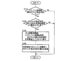
- step S10 it is determined whether or not a simultaneous request for an engine start request and a downshift request for the automatic transmission 18 has been made by an additional operation of the accelerator pedal 76 (after time t1 in FIG. 4). If the determination in S10 is negative, this routine is terminated. If the determination is affirmative, for example, engine start control is started in S20 corresponding to the hybrid control means 104 (time t2 in FIG. 4).
- S30 corresponding to the stepped shift control means 102 for example, downshift control is started (at time t3 in FIG. 4).
- the clutch pressure command value of the disengagement side clutch is set to the inertia phase start preparation pressure (after time t3 in FIG. 4).
- S40 corresponding to the K0 clutch engagement determining means 110 it is determined whether or not the engine connecting / disconnecting clutch K0 has been engaged, for example, with engine start control. That is, it is determined whether the inertia phase in the downshift process of the automatic transmission 18 has started. If the determination in S40 is negative, the process returns to S30.
- clutch K0 is the transmission input torque T AT as shown in broken lines when brought into complete engagement rises sharply, after shifting synchronous rotary transmission input rotational speed N IN is at the predetermined slope from here so as to rotate upward toward the speed N iN a, predicted transmission input torque T clutch pressure command value of the disengagement side clutch in accordance with the aT (thick solid line) is set (t4 after the time point of Fig. 4).
- the clutch pressure command value of the disengagement side clutch is once raised from the inertia phase start preparation pressure in accordance with the transmission input torque T AT.
- the clutch pressure command value of the engagement side clutch is completely determined from the constant pressure standby pressure immediately before the transmission input rotational speed N IN is synchronized with the synchronized rotational speed N IN a after the shift (at time t5 in FIG. 4) or after the rotational synchronization. It is gradually increased toward the maximum value for engagement.
- the transmission input rotational speed N IN is started to change toward the synchronized rotational speed N IN a after shifting. capturing the engagement completion and the rise of the transmission input torque T AT, is allowed to proceed for downshift (inertia phase) in response to the rising edge of the transmission input torque T AT from completion of engagement of the engine disconnecting clutch K0 (e.g. You can perform rotation control of the transmission input rotational speed N iN).
- the engine connection / disconnection is not performed in accordance with the low transmission input torque T AT before the completion of the engagement of the engine connection / disconnection clutch K0 in which the transmission input torque T AT has not yet risen, and the downshift (inertia phase) is not advanced. in response to the transmission input torque T AT rising from the completion of the engagement of the use clutch K0 it is allowed to proceed for downshift. Therefore, when the engine start control and the downshift control of the automatic transmission 18 are executed repeatedly, each control can be executed at an appropriate timing to suppress the shift shock.
- the transmission torque capacity in the automatic transmission 18 during EV traveling is equal to or greater than the transmission input torque T AT during EV traveling and when the engagement of the engine connecting / disconnecting clutch K0 is completed. since the transmission input torque T lower than aT in, during EV traveling drive torque is adequately transmitted.
- the automatic transmission 18 is caused to function as a torque limiter, and the engagement shock (synchronous shock) of the engine connecting / disconnecting clutch K0 at the time of starting the engine is suppressed.
- the control for setting the transmission torque capacity in the automatic transmission 18 during EV traveling to less than the transmission input torque T AT when the engagement of the engine connecting / disconnecting clutch K0 is completed is the engine start control and the automatic transmission 18 down.
- the shift control is executed in an overlapping manner, it is possible to suppress the deterioration of the durability of the automatic transmission 18.
- the inertia phase always starts after the engagement of the engine connecting / disconnecting clutch K0 is completed.
- the transmission input torque T AT during EV traveling is the motor torque T MG necessary for the EV traveling, and the transmission input torque when the engagement of the engine connecting / disconnecting clutch K0 is completed.
- T aT is because it is summed torque of EV traveling and the engine motor torque T MG and the engine torque T E required to start, the transmission torque capacity is appropriately predetermined range in the automatic transmission 18 in the EV traveling (EV traveling in transmission input torque T aT or at and and transmission input torque T lower than aT at the completion engagement of the engine disconnecting clutch K0) and the.
- the request for increasing the drive torque during EV traveling is a simultaneous request for the engine start request accompanying the increase in the accelerator opening Acc and the downshift request for the automatic transmission 18, so that the engine When the start control and the downshift control of the automatic transmission 18 are executed repeatedly, the driving torque corresponding to the accelerator operation is appropriately output while suppressing the shift shock.
- the control device AT related to the shift control of the automatic transmission 18 performs the engagement completion determination of the engine connecting / disconnecting clutch K0.
- the transmission output rotational speed N OUT that is the basis of the transmission input rotational speed N IN and the pre-shift synchronous rotational speed N IN b is originally used in the control device AT related to the shift control of the automatic transmission 18. Communication delay is unlikely to exist.
- the engine rotation speed NE and the motor rotation speed NMG are used in, for example, the control device ENG related to output control of the engine 14 and the control device MG related to drive control of the motor MG.
- the K0 clutch engagement determining means 110 determines whether or not the engagement / disengagement clutch K0 has been engaged, whether the actual transmission input rotational speed NIN and the synchronous rotational speed before shifting. The determination may be made by determining the start of the inertia phase in the downshift process of the automatic transmission 18 based on the difference rotational speed ⁇ N IN with N IN b.
- the engagement completion judgment of the clutch K0 based on differential speed .DELTA.N K0 and the actual motor rotation speed N MG and the actual engine rotational speed N E, the actual transmission input It can be used for backup of the start determination of the inertia phase based on the difference rotation speed ⁇ N IN between the rotation speed N IN and the synchronous rotation speed N IN b before the shift (for example, backup for checking the determination at the time of failure). is there.
- FIG. 5 is a functional block diagram for explaining a main part of the control function by the electronic control device 100, and is another embodiment corresponding to the functional block diagram of FIG.
- the time difference presence / absence determination unit that is, the time difference presence / absence determination means 112 is a time point t K0 when the K0 clutch engagement determination means determines the completion of engagement of the engine connecting / disconnecting clutch K0 based on the difference rotational speed ⁇ N K0 . It is determined whether or not there is a time difference ⁇ t K0 greater than or equal to a predetermined time difference from the time point t IN when the start of the inertia phase is determined based on the differential rotational speed ⁇ N IN by the K0 clutch engagement determination means.
- This predetermined time difference is a time difference determination value that is obtained and set in advance to determine that the time difference ⁇ t K0 is such that it is necessary to correct the engagement completion point of the engine connecting / disconnecting clutch K0 by learning control. .
- the learning control unit that is, the learning control unit 114 stores the time difference ⁇ t K0 as a learning value in a memory (storage device) (not shown) when the time difference presence / absence determination unit 112 determines that the time difference ⁇ t K0 is equal to or greater than the predetermined time difference. To do. Then, the learning control means 114, for example, when the engine start control alone without the downshift control is executed, the engine connection / disconnection clutch K0 based on the differential rotation speed ⁇ N K0 by the K0 clutch engagement determination means 110. When it is determined whether or not the engagement is completed, the time point ⁇ t K0 as the learning value is used to correct the determination point of the completion of the engagement of the engine connecting / disconnecting clutch K0.
- the time difference ⁇ t K0 as the learning value may be stored by overwriting the latest learning value, or may be stored for each type of shift (2 ⁇ 1 downshift, 3 ⁇ 2 downshift, etc.). good.
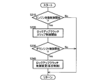
- FIG. 6 is a flowchart for explaining the control operation for learning and controlling the main part of the control operation of the electronic control unit 100, that is, the determination time point of completion of the engagement of the engine connecting / disconnecting clutch K0, for example, several msec to several tens msec. It is repeatedly executed with an extremely short cycle time.
- the flowchart of FIG. 6 is executed in addition to the flowchart of FIG. 3 in the first embodiment described above, for example.
- S110 corresponding to the K0 clutch engagement determining means 110, it is determined whether or not the engine connecting / disconnecting clutch K0 has been engaged, for example, with engine start control. If the determination in S110 is negative, the present routine is terminated. If the determination is positive, in S120 corresponding to the time difference presence / absence determination means 112, for example, when the completion of engagement of the engine connecting / disconnecting clutch K0 is determined. K0 and whether the time difference Delta] t K0 equal to or more than a predetermined time difference started and the time point t iN, which is determined in the inertia phase there is determined. If the determination in S120 is negative, this routine is terminated.
- the time difference ⁇ t K0 is stored as a learning value in a memory (storage device) (not shown). Is done.
- S140 corresponding to the learning control means 114 for example, when engine start control alone without downshift control is executed, based on the difference rotational speed ⁇ N K0 using the time difference ⁇ t K0 as the learning value. The determination time point of completion of engagement of the determined engine connecting / disconnecting clutch K0 is corrected.
- automatic is based on the difference rotational speed ⁇ N IN between the actual transmission input rotational speed N IN and the pre-shift synchronous rotational speed N IN b. Since the completion of the engagement of the engine connection / disconnection clutch K0 is determined by determining the start of the inertia phase in the downshift process of the transmission 18, the engagement of the engine connection / disconnection clutch K0 is determined only by the rotational speed in the automatic transmission 18. Completion (start of inertia phase) is determined. Thus, for example, as compared with determining the completion engagement of clutch K0 by using a engine rotational speed N E and the motor rotation speed N MG, determination delay hardly occurs.
- the time t K0 was determined complete engagement of clutch K0 based on differential speed .DELTA.N K0, to determine the start of the inertia phase based on differential speed .DELTA.N IN storing the time difference Delta] t K0 between time t iN, because to correct the time determining the engagement completion of the clutch K0 in the next start-up control of the engine 14 and the time difference Delta] t K0 as a learning value, the automatic transmission Including the start control of the engine 14 without the 18 downshift control, it is possible to more accurately determine the completion of the engagement of the engine connecting / disconnecting clutch K0 at the next engine start.
- the lockup clutch control means 106 controls the lockup clutch 38 of the torque converter 16 to the released or slipped state in order to suppress the occurrence of shock when the engine is started by the hybrid control means 104.
- the automatic transmission 18 functions as a torque limiter when the engagement of the engine connecting / disconnecting clutch K0 is completed.
- the engagement shock (synchronous shock) of the engine connecting / disconnecting clutch K0 at the time of starting the engine is suppressed. Therefore, when the downshift control of the automatic transmission 18 is executed in addition to the engine start control, the lockup clutch 38 of the torque converter 16 may be controlled to a completely engaged state (lockup on state). .
- transmission loss associated with the lock-up clutch 38 being released or slipped is suppressed.
- FIG. 7 is a functional block diagram for explaining a main part of the control function by the electronic control device 100, and is another embodiment corresponding to the functional block diagram of FIG.
- the control start determination unit that is, the control start determination unit 116 determines whether the engine start control is started by the hybrid control unit 104. Further, the control start determination unit 116 determines whether or not the downshift control of the automatic transmission 18 has been started by the stepped shift control unit 102.
- the lock-up clutch control means 106 controls the lock-up clutch 38 of the torque converter 16 to be released or slipped when the control start determination means 116 determines that the engine start control has been started. On the other hand, when it is determined by the drive torque increase request determination means 108 that the request for increasing the drive torque is made during the EV travel, the lockup clutch control means 106 is controlled by the control start determination means 116 of the automatic transmission 18. When it is determined that the downshift control has been started, the lockup clutch 38 of the torque converter 16 is controlled to the lockup on state.
- FIG. 8 is a flowchart for explaining a main part of the control operation of the electronic control unit 100, that is, a control operation for appropriately controlling the lock-up clutch 38. Executed. Further, the flowchart of FIG. 8 is executed in addition to the flowchart of FIG. 3 in the first embodiment described above, for example.
- S210 corresponding to the control start determination means 116, for example, it is determined whether engine start control has been started. If the determination in S210 is negative, this routine is terminated. If the determination is affirmative, for example, in S220 corresponding to the lockup clutch control means 106, the lockup clutch 38 is controlled to a released or slip state.
- S230 corresponding to the control start determination unit 116, for example, it is determined whether or not the downshift control of the automatic transmission 18 has been started. If the determination in S230 is negative, this routine is terminated. If the determination is positive, in S240 corresponding to the lockup clutch control means 106, for example, the lockup clutch 38 is changed from the released or slipped state to the lockup on state.
- Switching control is performed. As shown in the time chart of FIG. 4 in the first embodiment, when the engine start control is started, the lockup clutch 38 is controlled to be released or slipped (at time t2 in FIG. 4). Further, when the downshift control of the automatic transmission 18 is started, the lockup clutch 38 is switched from the released or slipped state to the lockup on state (time t3 in FIG. 4).
- the lockup clutch 38 is released or slip-controlled, while the downshift control of the automatic transmission 18 is executed in addition to the engine start control. Since the lock-up clutch 38 is sometimes engaged, transmission loss when executing the downshift control of the automatic transmission 18 in addition to the engine start control can be suppressed. In other words, by limiting the region for suppressing the deterioration of transmission efficiency associated with the release or slip control of the lock-up clutch 38 for suppressing the shock at the time of engine start, when executing the engine start control alone, It is possible to prevent the shock when starting the engine from getting worse. A shock at the time of starting the engine can be appropriately suppressed by appropriately controlling the lock-up clutch 38 according to the engine start control and the downshift control.
- Example of this invention was described in detail based on drawing, this invention can be implemented combining an Example mutually and is applied also in another aspect.
- each embodiment is implemented independently.
- the above embodiments are not necessarily implemented independently, and may be implemented in appropriate combination.
- the transmission input rotation speed N IN and the transmission output rotation speed N OUT are exemplified as the rotation speed at which communication delay hardly occurs, and the inertia phase is started based on the differential rotation speed ⁇ N IN.
- the present invention is not necessarily limited thereto.
- the differential rotation speed The completion of engagement of the engine connecting / disconnecting clutch K0 may be determined based on ⁇ N K0 . In short, it is only necessary to preferentially use the sensor value having a relatively small communication delay.
- the lock-up clutch 38 is exemplified as the second clutch that connects and disconnects the power transmission path between the electric motor MG and the automatic transmission 18.
- An engagement device provided alone in the power transmission path may be used.
- the engagement device that is engaged to form the shift stage of the automatic transmission 18 is a hydraulic friction engagement device such as the clutch C or the brake B, but is not limited thereto.
- other engagement devices such as an electromagnetic type, a magnetic type, and the like such as an electromagnetic clutch, a powder (magnetic powder) clutch, and a meshing type dog clutch may be used.
- the automatic transmission 18 is an automatic transmission that is controlled to be shifted to a shift speed determined based on a traveling state from a shift map. It may be a manual transmission or the like that is shifted to the right.
- the transmission output that can be converted from the vehicle required torque.
- the torque T OUT the transmission input torque T AT , the input torque of the power transmission device 12, and the like, this is not necessarily limited thereto.
- a transmission output torque T OUT or a transmission input torque T AT converted from an engine torque T E calculated so as to obtain a vehicle request output may be used as the vehicle request torque, or a torque sensor may be used.
- a directly detected torque value may be used.
- the torque converter 16 is used as the fluid transmission device.
- the torque converter 16 is not necessarily provided, and instead of the torque converter 16, a fluid coupling having no torque amplification action is provided.
- Other fluid transmissions such as (fluid coupling) may be used.
- Hybrid vehicle 14: Engine (driving drive power source) 16: Torque converter (fluid transmission) 18: Automatic transmission 34: Drive wheel 38: Lock-up clutch (second clutch) 100: Electronic control device (control device) K0: Engine disconnection clutch (clutch) MG: Electric motor (driving drive power source)
Abstract
Description
14:エンジン(走行用駆動力源)
16:トルクコンバータ(流体式伝動装置)
18:自動変速機
34:駆動輪
38:ロックアップクラッチ(第2クラッチ)
100:電子制御装置(制御装置)
K0:エンジン断接用クラッチ(クラッチ)
MG:電動機(走行用駆動力源)
Claims (8)
- 走行用駆動力源としてのエンジン及び電動機と、該エンジンと該電動機との間の動力伝達経路を断接するクラッチと、該電動機に動力伝達可能に連結されて該走行用駆動力源からの動力を駆動輪側へ伝達する自動変速機とを備え、該クラッチを解放した状態で該電動機のみを走行用駆動力源として走行するモータ走行が可能なハイブリッド車両の制御装置であって、
前記モータ走行中に駆動トルクを増大する要求が為されたときに前記エンジンの始動制御と前記自動変速機のダウンシフト制御とを重ねて実行する場合には、前記クラッチの係合完了を起点として、該自動変速機の入力回転速度を変速後の同期回転速度に向けて回転変化させることを開始することを特徴とするハイブリッド車両の制御装置。 - 前記モータ走行中の前記自動変速機における伝達トルク容量を、該モータ走行中における該自動変速機の入力トルク以上であって、前記クラッチの係合完了時における該自動変速機の入力トルク未満とすることを特徴とする請求項1に記載のハイブリッド車両の制御装置。
- 前記モータ走行中における前記自動変速機の入力トルクは、該モータ走行に必要な前記電動機の出力トルクであり、
前記クラッチの係合完了時における前記自動変速機の入力トルクは、前記モータ走行及び前記エンジンの始動に必要な前記電動機の出力トルクと前記エンジンの出力トルクとの合算トルクであることを特徴とする請求項2に記載のハイブリッド車両の制御装置。 - 前記電動機と前記自動変速機との間の動力伝達経路を断接する第2クラッチを更に備え、
前記エンジンの始動制御を実行するときには、前記第2クラッチを解放乃至スリップ制御する一方で、該エンジンの始動制御に加えて前記自動変速機のダウンシフト制御を実行するときには、該第2クラッチを係合することを特徴とする請求項1乃至3の何れか1項に記載のハイブリッド車両の制御装置。 - 前記第2クラッチは、流体式伝動装置に備えられたロックアップクラッチであることを特徴とする請求項4に記載のハイブリッド車両の制御装置。
- 前記自動変速機の実際の出力回転速度と変速前の変速比とから算出される該自動変速機の入力回転速度の同期回転速度と、該自動変速機の実際の入力回転速度との差回転速度に基づいて該自動変速機のダウンシフト過程におけるイナーシャ相の開始を判定し、
該イナーシャ相の開始を判定することで前記クラッチの係合完了を判定することを特徴とする請求項1乃至5の何れか1項に記載のハイブリッド車両の制御装置。 - 前記エンジンの実際の回転速度と前記電動機の実際の回転速度との差回転速度に基づいて前記クラッチの係合完了を判定した時点と、前記イナーシャ相の開始を判定した時点との時間差を記憶し、該時間差を学習値として前記エンジンの次回の始動制御において該クラッチの係合完了を判定する時点を補正することを特徴とする請求項6に記載のハイブリッド車両の制御装置。
- 前記モータ走行中に駆動トルクを増大する要求は、アクセル開度の増大に伴う前記エンジンの始動要求と前記自動変速機のダウンシフト要求との同時要求であることを特徴とする請求項1乃至7の何れか1項に記載のハイブリッド車両の制御装置。
Priority Applications (5)
| Application Number | Priority Date | Filing Date | Title |
|---|---|---|---|
| CN201180064991.4A CN103391869B (zh) | 2011-01-12 | 2011-01-12 | 混合动力车辆的控制装置 |
| EP11855332.0A EP2664510B1 (en) | 2011-01-12 | 2011-01-12 | Hybrid vehicle control apparatus |
| PCT/JP2011/050378 WO2012095970A1 (ja) | 2011-01-12 | 2011-01-12 | ハイブリッド車両の制御装置 |
| US13/979,526 US8996265B2 (en) | 2011-01-12 | 2011-01-12 | Control device of hybrid vehicle |
| JP2012552571A JP5926197B2 (ja) | 2011-01-12 | 2011-01-12 | ハイブリッド車両の制御装置 |
Applications Claiming Priority (1)
| Application Number | Priority Date | Filing Date | Title |
|---|---|---|---|
| PCT/JP2011/050378 WO2012095970A1 (ja) | 2011-01-12 | 2011-01-12 | ハイブリッド車両の制御装置 |
Publications (1)
| Publication Number | Publication Date |
|---|---|
| WO2012095970A1 true WO2012095970A1 (ja) | 2012-07-19 |
Family
ID=46506893
Family Applications (1)
| Application Number | Title | Priority Date | Filing Date |
|---|---|---|---|
| PCT/JP2011/050378 WO2012095970A1 (ja) | 2011-01-12 | 2011-01-12 | ハイブリッド車両の制御装置 |
Country Status (5)
| Country | Link |
|---|---|
| US (1) | US8996265B2 (ja) |
| EP (1) | EP2664510B1 (ja) |
| JP (1) | JP5926197B2 (ja) |
| CN (1) | CN103391869B (ja) |
| WO (1) | WO2012095970A1 (ja) |
Cited By (8)
| Publication number | Priority date | Publication date | Assignee | Title |
|---|---|---|---|---|
| JP2014073705A (ja) * | 2012-10-02 | 2014-04-24 | Toyota Motor Corp | 車両用の制御装置 |
| JP2014151907A (ja) * | 2013-02-05 | 2014-08-25 | Toyota Motor Corp | ハイブリッド車両の制御装置 |
| JP2014151909A (ja) * | 2013-02-05 | 2014-08-25 | Toyota Motor Corp | ハイブリッド車両の制御装置 |
| JP2014234064A (ja) * | 2013-05-31 | 2014-12-15 | 富士重工業株式会社 | 制御装置 |
| WO2016031050A1 (ja) * | 2014-08-29 | 2016-03-03 | 日産自動車株式会社 | 車両のロックアップクラッチ制御装置 |
| WO2017057757A1 (ja) * | 2015-09-30 | 2017-04-06 | アイシン・エィ・ダブリュ株式会社 | 制御装置 |
| WO2017149589A1 (ja) * | 2016-02-29 | 2017-09-08 | 新潟原動機株式会社 | 船舶推進方法及び船舶推進装置 |
| US11597377B2 (en) * | 2021-06-22 | 2023-03-07 | Toyota Jidosha Kabushiki Kaisha | Control apparatus for vehicle |
Families Citing this family (32)
| Publication number | Priority date | Publication date | Assignee | Title |
|---|---|---|---|---|
| CN103534158A (zh) * | 2011-05-16 | 2014-01-22 | 丰田自动车株式会社 | 混合动力车辆的控制装置 |
| US9199633B2 (en) * | 2011-12-16 | 2015-12-01 | Toyota Jidosha Kabushiki Kaisha | Control device for hybrid vehicle |
| US8956263B2 (en) * | 2012-08-06 | 2015-02-17 | GM Global Technology Operations LLC | Method and apparatus for executing a transmission range shift in a multi-mode powertrain system |
| JP5618105B2 (ja) * | 2013-01-09 | 2014-11-05 | 三菱自動車工業株式会社 | ハイブリッド車両の制御装置 |
| MX346023B (es) * | 2013-09-27 | 2017-03-02 | Nissan Motor | Vehiculo hibrido. |
| US9771064B2 (en) * | 2014-03-25 | 2017-09-26 | Ford Global Technologies, Llc | Systems and methods for improving vehicle driveline operation |
| US10207696B2 (en) * | 2014-06-09 | 2019-02-19 | Ford Global Technologies, Llc | Timing transmission gearing shifts for a hybrid electric powertrain |
| KR101573625B1 (ko) * | 2014-08-12 | 2015-12-01 | 현대자동차주식회사 | 하이브리드 차량의 변속 제어 장치 및 방법 |
| CN104842994A (zh) * | 2014-08-29 | 2015-08-19 | 北汽福田汽车股份有限公司 | 发动机启动控制方法及系统 |
| US9475483B2 (en) * | 2014-11-19 | 2016-10-25 | Ford Global Technologies, Llc | Hybrid vehicle including a prevent powertrain gear hunting strategy |
| US9731706B2 (en) * | 2015-03-24 | 2017-08-15 | Ford Global Technologies, Llc | Coordinating non-demand engine start and stop with gear shift |
| CN107428333B (zh) * | 2015-03-31 | 2019-11-05 | 爱信艾达株式会社 | 控制装置 |
| WO2016158928A1 (ja) * | 2015-03-31 | 2016-10-06 | アイシン・エィ・ダブリュ株式会社 | 制御装置 |
| KR101703613B1 (ko) * | 2015-06-19 | 2017-02-07 | 현대자동차 주식회사 | 하이브리드 차량의 엔진 기동 시점 제어 방법 및 그 제어 장치 |
| JP2017020574A (ja) * | 2015-07-10 | 2017-01-26 | トヨタ自動車株式会社 | 電動車両の制御装置 |
| KR101714521B1 (ko) * | 2015-11-06 | 2017-03-22 | 현대자동차주식회사 | 하이브리드 자동차 및 그를 위한 효율적인 변속 제어 방법 |
| US10183671B2 (en) * | 2016-07-18 | 2019-01-22 | Caterpillar Inc. | Torque converter lockup control |
| US9981651B2 (en) * | 2016-07-27 | 2018-05-29 | Ford Global Technologies, Llc | Torque modification during an upshift in a hybrid vehicle |
| US10479343B2 (en) * | 2016-10-31 | 2019-11-19 | Ford Global Technologies, Llc | Methods and systems for engine-off disengagement of a vehicle park state |
| KR102659047B1 (ko) * | 2016-12-16 | 2024-04-19 | 현대자동차주식회사 | 하이브리드 자동차 및 그를 위한 모드 전환 제어 방법 |
| JP6673817B2 (ja) * | 2016-12-23 | 2020-03-25 | トヨタ自動車株式会社 | ハイブリッド車両の制御装置 |
| US10428938B2 (en) * | 2017-07-21 | 2019-10-01 | GM Global Technology Operations LLC | Method and system for controlling a vehicle propulsion system |
| DE102018200777A1 (de) * | 2018-01-18 | 2019-07-18 | Zf Friedrichshafen Ag | Getriebesteuerung |
| JP6922757B2 (ja) * | 2018-01-24 | 2021-08-18 | トヨタ自動車株式会社 | 自動変速機の制御装置 |
| WO2020203706A1 (ja) * | 2019-03-29 | 2020-10-08 | アイシン・エィ・ダブリュ株式会社 | ハイブリッド駆動装置 |
| JP7201564B2 (ja) * | 2019-09-27 | 2023-01-10 | トヨタ自動車株式会社 | ハイブリッド車両およびその制御方法 |
| KR102250117B1 (ko) * | 2019-12-13 | 2021-05-10 | 주식회사 현대케피코 | 하이브리드 차량의 엔진 시동 방법 |
| JP7322765B2 (ja) * | 2020-03-17 | 2023-08-08 | トヨタ自動車株式会社 | 車両の制御装置 |
| JP7252169B2 (ja) * | 2020-03-30 | 2023-04-04 | トヨタ自動車株式会社 | ハイブリッド車両の制御装置 |
| KR20210153799A (ko) * | 2020-06-10 | 2021-12-20 | 현대자동차주식회사 | 하이브리드 차량의 변속 및 엔진클러치 접합 제어 방법 및 장치 |
| CN111852668B (zh) * | 2020-07-29 | 2022-08-02 | 重庆嘉陵全域机动车辆有限公司 | 一种混合动力全地形车发动机起动控制方法 |
| CN112360971B (zh) * | 2020-11-25 | 2022-04-01 | 一汽解放汽车有限公司 | 一种基于换挡动作重叠的换挡控制方法 |
Citations (7)
| Publication number | Priority date | Publication date | Assignee | Title |
|---|---|---|---|---|
| JP2004140993A (ja) * | 2003-10-10 | 2004-05-13 | Toyota Motor Corp | ハイブリッド車両の制御装置 |
| JP2006306210A (ja) | 2005-04-27 | 2006-11-09 | Nissan Motor Co Ltd | ハイブリッド駆動装置のエンジン始動方法 |
| JP2008044521A (ja) * | 2006-08-15 | 2008-02-28 | Nissan Motor Co Ltd | ハイブリッド車両の電気走行制御装置 |
| JP2008179242A (ja) | 2007-01-24 | 2008-08-07 | Nissan Motor Co Ltd | ハイブリッド車両の変速時モード切り替え制御装置 |
| JP2008207643A (ja) | 2007-02-26 | 2008-09-11 | Nissan Motor Co Ltd | ハイブリッド車両のエンジン始動制御装置 |
| JP2008254725A (ja) * | 2007-03-12 | 2008-10-23 | Nissan Motor Co Ltd | ハイブリッド車両のエンジン始動制御装置 |
| JP2010143426A (ja) * | 2008-12-19 | 2010-07-01 | Nissan Motor Co Ltd | ハイブリッド車両のエンジン始動制御装置 |
Family Cites Families (9)
| Publication number | Priority date | Publication date | Assignee | Title |
|---|---|---|---|---|
| US3805640A (en) * | 1972-09-08 | 1974-04-23 | Twin Disc Inc | Electronically controlled power transmission |
| US4811223A (en) * | 1985-06-04 | 1989-03-07 | Toyota Jidosha Kabushiki Kaisha | System for controlling engine torque |
| JP3214427B2 (ja) * | 1997-12-12 | 2001-10-02 | トヨタ自動車株式会社 | ハイブリッド車の駆動制御装置 |
| JP4265572B2 (ja) * | 2005-06-01 | 2009-05-20 | トヨタ自動車株式会社 | 動力出力装置およびこれを搭載する車両並びに動力出力装置の制御方法 |
| JP2007069804A (ja) * | 2005-09-08 | 2007-03-22 | Nissan Motor Co Ltd | ハイブリッド車両のエンジン始動応答改善装置 |
| JP4341610B2 (ja) * | 2005-11-09 | 2009-10-07 | 日産自動車株式会社 | ハイブリッド車両のエンジン再始動制御装置 |
| JP2007261498A (ja) * | 2006-03-29 | 2007-10-11 | Nissan Motor Co Ltd | ハイブリッド車両の伝動状態切り替え制御装置 |
| DE102006031684A1 (de) * | 2006-07-08 | 2008-01-10 | Zf Friedrichshafen Ag | Verfahren zum Betreiben eines Antriebsstrangs |
| US8204659B2 (en) * | 2007-03-12 | 2012-06-19 | Nissan Motor Co., Ltd. | Engine start control system for hybrid vehicle |
-
2011
- 2011-01-12 CN CN201180064991.4A patent/CN103391869B/zh active Active
- 2011-01-12 WO PCT/JP2011/050378 patent/WO2012095970A1/ja active Application Filing
- 2011-01-12 JP JP2012552571A patent/JP5926197B2/ja active Active
- 2011-01-12 US US13/979,526 patent/US8996265B2/en active Active
- 2011-01-12 EP EP11855332.0A patent/EP2664510B1/en active Active
Patent Citations (7)
| Publication number | Priority date | Publication date | Assignee | Title |
|---|---|---|---|---|
| JP2004140993A (ja) * | 2003-10-10 | 2004-05-13 | Toyota Motor Corp | ハイブリッド車両の制御装置 |
| JP2006306210A (ja) | 2005-04-27 | 2006-11-09 | Nissan Motor Co Ltd | ハイブリッド駆動装置のエンジン始動方法 |
| JP2008044521A (ja) * | 2006-08-15 | 2008-02-28 | Nissan Motor Co Ltd | ハイブリッド車両の電気走行制御装置 |
| JP2008179242A (ja) | 2007-01-24 | 2008-08-07 | Nissan Motor Co Ltd | ハイブリッド車両の変速時モード切り替え制御装置 |
| JP2008207643A (ja) | 2007-02-26 | 2008-09-11 | Nissan Motor Co Ltd | ハイブリッド車両のエンジン始動制御装置 |
| JP2008254725A (ja) * | 2007-03-12 | 2008-10-23 | Nissan Motor Co Ltd | ハイブリッド車両のエンジン始動制御装置 |
| JP2010143426A (ja) * | 2008-12-19 | 2010-07-01 | Nissan Motor Co Ltd | ハイブリッド車両のエンジン始動制御装置 |
Non-Patent Citations (1)
| Title |
|---|
| See also references of EP2664510A4 |
Cited By (10)
| Publication number | Priority date | Publication date | Assignee | Title |
|---|---|---|---|---|
| JP2014073705A (ja) * | 2012-10-02 | 2014-04-24 | Toyota Motor Corp | 車両用の制御装置 |
| JP2014151907A (ja) * | 2013-02-05 | 2014-08-25 | Toyota Motor Corp | ハイブリッド車両の制御装置 |
| JP2014151909A (ja) * | 2013-02-05 | 2014-08-25 | Toyota Motor Corp | ハイブリッド車両の制御装置 |
| JP2014234064A (ja) * | 2013-05-31 | 2014-12-15 | 富士重工業株式会社 | 制御装置 |
| WO2016031050A1 (ja) * | 2014-08-29 | 2016-03-03 | 日産自動車株式会社 | 車両のロックアップクラッチ制御装置 |
| US9920796B2 (en) | 2014-08-29 | 2018-03-20 | Nissan Motor Co., Ltd. | Vehicle lock-up clutch control device |
| WO2017057757A1 (ja) * | 2015-09-30 | 2017-04-06 | アイシン・エィ・ダブリュ株式会社 | 制御装置 |
| WO2017149589A1 (ja) * | 2016-02-29 | 2017-09-08 | 新潟原動機株式会社 | 船舶推進方法及び船舶推進装置 |
| JP6214075B1 (ja) * | 2016-02-29 | 2017-10-25 | 新潟原動機株式会社 | 船舶推進方法及び船舶推進装置 |
| US11597377B2 (en) * | 2021-06-22 | 2023-03-07 | Toyota Jidosha Kabushiki Kaisha | Control apparatus for vehicle |
Also Published As
| Publication number | Publication date |
|---|---|
| EP2664510B1 (en) | 2016-12-07 |
| EP2664510A4 (en) | 2016-04-27 |
| CN103391869A (zh) | 2013-11-13 |
| CN103391869B (zh) | 2016-01-06 |
| JP5926197B2 (ja) | 2016-06-01 |
| EP2664510A1 (en) | 2013-11-20 |
| EP2664510A8 (en) | 2014-01-08 |
| US20140018207A1 (en) | 2014-01-16 |
| JPWO2012095970A1 (ja) | 2014-06-09 |
| US8996265B2 (en) | 2015-03-31 |
Similar Documents
| Publication | Publication Date | Title |
|---|---|---|
| JP5926197B2 (ja) | ハイブリッド車両の制御装置 | |
| JP6003915B2 (ja) | ハイブリッド車両の制御装置 | |
| JP5609993B2 (ja) | ハイブリッド車両の制御装置 | |
| JP5867440B2 (ja) | 車両の制御装置 | |
| US10858008B2 (en) | Control apparatus for hybrid vehicle | |
| JP5772979B2 (ja) | ハイブリッド車両の制御装置 | |
| JP5644946B2 (ja) | 車両の制御装置 | |
| JP2014104776A (ja) | ハイブリッド車両の制御装置 | |
| JP5472483B2 (ja) | 車両用動力伝達装置の制御装置 | |
| WO2014045412A1 (ja) | 車両の制御装置 | |
| WO2014170948A1 (ja) | ハイブリッド車両の制御装置 | |
| WO2014097376A1 (ja) | 車両の制御装置 | |
| WO2013088576A1 (ja) | ハイブリッド車両の制御装置 | |
| JP5794377B2 (ja) | 車両の制御装置 | |
| US9776620B2 (en) | Control system for hybrid vehicle | |
| JP2017100597A (ja) | 車両の制御装置 | |
| JP2023102682A (ja) | 有段変速機の制御装置 | |
| JP2023008333A (ja) | ハイブリッド車両の制御装置 | |
| JP2023069078A (ja) | 車両の制御装置 | |
| JP2023122426A (ja) | ハイブリッド車両の制御装置 | |
| JP2022112446A (ja) | 車両の制御装置 | |
| JP2022148898A (ja) | 車両の制御装置 | |
| JP2023094427A (ja) | 車両の制御装置 | |
| JP2023109109A (ja) | 車両の制御装置 | |
| JP2023008334A (ja) | ハイブリッド車両の制御装置 |
Legal Events
| Date | Code | Title | Description |
|---|---|---|---|
| 121 | Ep: the epo has been informed by wipo that ep was designated in this application |
Ref document number: 11855332 Country of ref document: EP Kind code of ref document: A1 |
|
| DPE1 | Request for preliminary examination filed after expiration of 19th month from priority date (pct application filed from 20040101) | ||
| ENP | Entry into the national phase |
Ref document number: 2012552571 Country of ref document: JP Kind code of ref document: A |
|
| NENP | Non-entry into the national phase |
Ref country code: DE |
|
| REEP | Request for entry into the european phase |
Ref document number: 2011855332 Country of ref document: EP |
|
| WWE | Wipo information: entry into national phase |
Ref document number: 2011855332 Country of ref document: EP |
|
| WWE | Wipo information: entry into national phase |
Ref document number: 13979526 Country of ref document: US |