WO2012090591A1 - Dispositif d'affichage - Google Patents
Dispositif d'affichage Download PDFInfo
- Publication number
- WO2012090591A1 WO2012090591A1 PCT/JP2011/075772 JP2011075772W WO2012090591A1 WO 2012090591 A1 WO2012090591 A1 WO 2012090591A1 JP 2011075772 W JP2011075772 W JP 2011075772W WO 2012090591 A1 WO2012090591 A1 WO 2012090591A1
- Authority
- WO
- WIPO (PCT)
- Prior art keywords
- light
- unit
- display
- light guide
- refractive index
- Prior art date
Links
- 238000009792 diffusion process Methods 0.000 claims description 22
- 238000010422 painting Methods 0.000 description 3
- 229920003002 synthetic resin Polymers 0.000 description 3
- 239000000057 synthetic resin Substances 0.000 description 3
- 230000002238 attenuated effect Effects 0.000 description 2
- 230000007423 decrease Effects 0.000 description 2
- 238000010586 diagram Methods 0.000 description 2
- 238000005516 engineering process Methods 0.000 description 2
- 239000000463 material Substances 0.000 description 2
- 238000000034 method Methods 0.000 description 2
- NIXOWILDQLNWCW-UHFFFAOYSA-N acrylic acid group Chemical group C(C=C)(=O)O NIXOWILDQLNWCW-UHFFFAOYSA-N 0.000 description 1
- 230000003247 decreasing effect Effects 0.000 description 1
- 238000005530 etching Methods 0.000 description 1
- 239000011521 glass Substances 0.000 description 1
- PCHJSUWPFVWCPO-UHFFFAOYSA-N gold Chemical compound [Au] PCHJSUWPFVWCPO-UHFFFAOYSA-N 0.000 description 1
- 230000001788 irregular Effects 0.000 description 1
- 238000010030 laminating Methods 0.000 description 1
- 238000012986 modification Methods 0.000 description 1
- 230000004048 modification Effects 0.000 description 1
- 239000012466 permeate Substances 0.000 description 1
- 229920000515 polycarbonate Polymers 0.000 description 1
- 239000004417 polycarbonate Substances 0.000 description 1
Images


Classifications
-
- G—PHYSICS
- G09—EDUCATION; CRYPTOGRAPHY; DISPLAY; ADVERTISING; SEALS
- G09F—DISPLAYING; ADVERTISING; SIGNS; LABELS OR NAME-PLATES; SEALS
- G09F13/00—Illuminated signs; Luminous advertising
- G09F13/18—Edge-illuminated signs
-
- B—PERFORMING OPERATIONS; TRANSPORTING
- B60—VEHICLES IN GENERAL
- B60K—ARRANGEMENT OR MOUNTING OF PROPULSION UNITS OR OF TRANSMISSIONS IN VEHICLES; ARRANGEMENT OR MOUNTING OF PLURAL DIVERSE PRIME-MOVERS IN VEHICLES; AUXILIARY DRIVES FOR VEHICLES; INSTRUMENTATION OR DASHBOARDS FOR VEHICLES; ARRANGEMENTS IN CONNECTION WITH COOLING, AIR INTAKE, GAS EXHAUST OR FUEL SUPPLY OF PROPULSION UNITS IN VEHICLES
- B60K35/00—Arrangement of adaptations of instruments
-
- B60K35/60—
-
- B60K2360/33—
-
- B60K2360/34—
-
- G—PHYSICS
- G09—EDUCATION; CRYPTOGRAPHY; DISPLAY; ADVERTISING; SEALS
- G09F—DISPLAYING; ADVERTISING; SIGNS; LABELS OR NAME-PLATES; SEALS
- G09F13/00—Illuminated signs; Luminous advertising
- G09F13/18—Edge-illuminated signs
- G09F2013/184—Information to display
- G09F2013/1854—Light diffusing layer
-
- G—PHYSICS
- G09—EDUCATION; CRYPTOGRAPHY; DISPLAY; ADVERTISING; SEALS
- G09F—DISPLAYING; ADVERTISING; SIGNS; LABELS OR NAME-PLATES; SEALS
- G09F13/00—Illuminated signs; Luminous advertising
- G09F13/18—Edge-illuminated signs
- G09F2013/184—Information to display
- G09F2013/1863—Layer with different refractive index
-
- G—PHYSICS
- G09—EDUCATION; CRYPTOGRAPHY; DISPLAY; ADVERTISING; SEALS
- G09F—DISPLAYING; ADVERTISING; SIGNS; LABELS OR NAME-PLATES; SEALS
- G09F13/00—Illuminated signs; Luminous advertising
- G09F13/20—Illuminated signs; Luminous advertising with luminescent surfaces or parts
- G09F13/22—Illuminated signs; Luminous advertising with luminescent surfaces or parts electroluminescent
- G09F2013/222—Illuminated signs; Luminous advertising with luminescent surfaces or parts electroluminescent with LEDs
Definitions
- the present invention relates to a display device mounted on an automobile or the like that guides light emitted from a light source by a light guide unit to illuminate a design display unit or the like.
- Patent Documents 1 to 3 As this kind of technology, for example, in Patent Documents 1 to 3, a sheet-like sheet-like member having flexibility and translucency, and light more than a sheet-like member arranged on both surfaces of the sheet-like member. A light guide including a low refractive index portion having a low refractive index is disclosed.
- the light guides disclosed in Patent Documents 1 to 3 do not consider a design in which the light emitted from the light guide is guided, and therefore a predetermined design using the light guide is not considered.
- the applicant of the present application guides light incident from the end of the light guide member, and provides a light diffusing part in accordance with the design display part, so that light is emitted from an extra part in the light guide part.
- a display device that can prevent or reduce and efficiently illuminate the indicator portion displayed by the design display portion (Japanese Patent Application No. 2010-110608).
- the display device has a problem that the closer to the light source, the higher the emission luminance of the indicator portion, and the light is attenuated and the emission luminance is lowered as the distance from the light source to the indicator portion increases.
- a large amount of light is emitted (consumed) in order from the indicator part closest to the light source.
- the indicator part located at there is a problem that the light emission luminance is lowered.
- the indicator portion located behind the hole opened for the purpose of inserting the pointer shaft or the like as viewed from the light source causes a shadow of the hole and the luminance decreases.
- the light reflected from the end face brightens the vicinity of the end face and causes uneven brightness.
- the present invention provides a display device capable of illuminating all index portions with substantially uniform brightness regardless of the distance from the light source to the index portion and the positional relationship of the index portions. It is intended.
- the present invention provides a light source, a light guide unit that guides light emitted from the light source, and a design display unit that includes a light emission unit that emits the light.
- the low-refractive-index part which is provided between the light guide part and the design display part and has a light refractive index lower than that of the light guide part, and is formed in the light guide part and guides the light guide part.
- a display light adjusting unit for changing the emission efficiency is provided at least in a region corresponding to the light emitting unit.
- the display light adjusting unit is constituted by the light diffusing unit and a light adjusting low refractive index unit.
- an indicator portion (light emitting portion) that transmits light in accordance with the design of the design display portion, and providing an opaque portion that does not transmit light other than that, an extra portion of the light guide portion is provided. It is possible to prevent or reduce the emission of light and efficiently illuminate the design displayed by the design display unit. In addition, it is possible to provide a display device that can illuminate all index parts with substantially uniform luminance regardless of the distance from the light source to the index part and the positional relationship of the index parts.
- FIG. 2 (second embodiment diagram) Schematic diagram of the light path in the light guide Sectional drawing of the display apparatus of 3rd embodiment Sectional drawing of the display apparatus of 4th embodiment Sectional drawing of the display apparatus of 5th embodiment Sectional drawing of the display apparatus of 6th embodiment
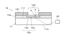
- the display device 100 includes a display member 10 that displays a predetermined design and a light source 20 that emits light.
- the display device 100 receives light emitted from the light source 20 at the end of the display member 10 and emits it from a predetermined region of the display member 10.
- the display device 100 is used for, for example, a vehicle instrument, a mobile phone, a display display, and the like.
- the display device 100 is a vehicle instrument.
- the light source 20 is a rod-shaped light source that emits light in a straight line, and is composed of, for example, a light-emitting element such as a cold cathode tube, a light-emitting diode, or an organic EL element.
- the light source 20 is provided at a position where incident light enters the display member 10 (light guide unit 11 described later). Specifically, for example, the light source 20 is provided so that the light emitting portion of the light source 20 faces the side surface of the display member 10 (light guide portion 11 described later), and the light emitted from the light source 20 is guided. Incident into the light unit 11.
- the display member 10 includes a light guide portion 11, a design display portion 12, a surface light diffusion portion 13 a, a back light diffusion portion 13 b, a low refractive index portion 14 a, and a light adjustment low refractive index.
- the display light adjusting unit 15 is a surface light adjusting unit 15a including a surface light diffusing unit 13a and a light adjusting low refractive index unit 14b, or a back light adjusting unit including a back light diffusing unit 13b and a light adjusting low refractive index unit 14b. Part 15b.
- the light guide unit 11 takes in the light emitted from the light source 20 and guides it.
- the light guide unit 11 is formed of a plate-shaped synthetic resin member (for example, a polycarbonate plate or the like) having transparent or translucent translucency (including translucency).
- the design display unit 12 is disposed on the surface 111 side of the light guide unit 11 and does not emit (does not transmit) light, and an indicator unit (light emitting unit) that emits light and displays a design or the like brightly. 122.
- the opaque portion 121 is formed by printing, painting, etc., using light-shielding ink, etc., and forms a design by cutting out the design of a vehicle instrument (design representing characters, pictures, figures, symbols, etc.) To do.
- the non-transmissive portion 121 may be a layer having translucency (including semi-translucency).
- the indicator part 122 is a part of the design of the vehicle instrument cut out in the non-permeable part 121 as a through hole (can be changed to a notch as appropriate).
- the indicator part 122 is formed by drawing printing or the like.
- the indicator part 122 should just be what can permeate
- the indicator portion 122 that transmits light is provided in accordance with the design of the design display portion 12, and the light transmitting portion 121 that does not transmit light otherwise is used as the light from an extra portion of the light guide portion 11. Can be prevented or reduced, and the design displayed by the design display unit 12 can be efficiently illuminated.
- the light diffusing unit 13 (the front surface light diffusing unit 13a and the back surface light diffusing unit 13b) is provided on the front surface 111 or the back surface 112 of the light guiding unit 11 by printing, painting or the like using a material having light diffusibility. 11 diffuses the light guided. The diffused light passes through the indicator portion 122 and exits from the indicator portion 122.
- the light diffusing unit 13 is provided in a region corresponding to the indicator unit 122. For example, the light diffusing unit 13 is provided so that at least a part thereof overlaps the indicator unit 122 when viewed from the normal direction of the surface of the design display unit 12.
- the light diffusing unit 13 may be larger than the index unit 122, for example, may have a wider shape than the index unit 122, or may have a similar shape larger than the index unit 122. good. Thereby, even if the light diffusing unit 13 is provided at a position shifted from the index unit 122 (that is, a position deviated from the region corresponding to the index unit 122), the light can be diffused toward the index unit 122.
- the indicator unit 122 can efficiently emit the light diffused by the light diffusing unit 13. In addition, the viewing angle of the index unit 122 is widened.
- the light diffusion part 13 should just be the structure which has light diffusivity, for example, the light diffusion part 13 is a dot pattern etc. which consists of an uneven
- the light diffusing unit 13 may be provided with light diffusing bubbles on the surface of the light guiding unit 11 having translucency.
- the light diffusion part 13 may be provided with the same material as the light guide part 11.
- the light guide part 11 and the light diffusion part 13 may be configured by mixing light-diffusing gold powder or the like in a light-transmitting glass.
- the light diffusing unit 13 is a film (sheet) -like member having light diffusibility, and this is provided on the back surface 112 of the light guide unit 11.
- the light diffusing unit 13 is provided at substantially the same position and the same shape as the indicator unit 122. With such a configuration, the light diffusing unit 13 can be provided without requiring a complicated design. Note that the term “diffusion” as used herein appropriately includes changing the course of light by irregular reflection, scattering, refraction, reflection, or the like.
- the surface light diffusing unit 13a is a transmissive light diffusing unit disposed on the surface 111 of the light guide unit 11, and mainly scatters and refracts light incident from the surface 111 of the light guide unit 11 toward the indicator unit 122 side. Etc. to diffuse light.
- the back surface light diffusing unit 13b is disposed on the back surface 112 of the light guide unit 11 and is an impermeable light diffusing unit. Light incident from the back surface 112 of the light guide unit 11 is directed to the light guide unit 11 side. Diffuse light by reflection, diffuse reflection, scattering, etc. A part of the back surface 112 of the light guide portion 11 excluding the back surface light diffusion portion 13b is an exposed surface 113 that touches the air layer.
- the low refractive index portion 14 a is provided so as to cover the entire surface 111 of the light guide portion 11.
- the light adjusting low refractive index portion 14b is disposed between the light guide portion 11 and the light diffusion portion 13 (the front surface light diffusion portion 13a and the back surface light diffusion portion 13b).
- the low refractive index portion 14a and the light adjusting low refractive index portion 14b are transparent or translucent (including semi-transparent) and have a lower refractive index of light than the light guide unit 11.
- the low refractive index portion 14a and the light adjusting low refractive index portion 14b are formed by printing, painting, or the like using, for example, a synthetic resin having a light refractive index lower than that of the light guide portion 11.
- the low refractive index portion 14a and the light adjusting low refractive index portion 14b may be provided by a flat plate-shaped synthetic resin member (for example, an acrylic plate) having translucency.
- the display light adjusting unit 15 includes a surface light adjusting unit 15a (see FIG. 4) including a surface light diffusing unit 13a and a light adjusting low refractive index unit 14b, a back light diffusing unit 13b, and a light adjusting low refractive index unit 14b. And a back light adjusting unit 15b (see FIG. 3).
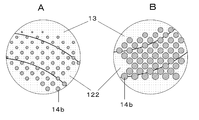
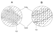
- the display light adjusting unit 15 is formed by disposing the light adjusting low refractive index portion 14b in a dot pattern (by printing).
- the display light adjusting unit 15 may be provided by providing a dot-patterned light diffusing unit 13 (front surface light diffusing unit 13 a or back surface light diffusing unit 13 b).
- the display device is configured by the above configuration. In the following description, a method for adjusting the light emission rate in the display light adjusting unit 15 will be described.
- the light emitted from the light source 20 enters the light guide 11, repeats reflection at the interface of the light guide 11, and travels in the light guide 11.
- the first light beam 20 a totally reflected by the light adjusting low refractive index unit 14 b and the second light beam 20 b diffused by the light diffusion unit 13. And divided.
- the first light ray 20a is further totally reflected by the light adjusting low refractive index portion 14b and further travels in the light guide portion 11.
- the second light beam 20b diffused by the light diffusing unit 13 is emitted from the index unit 122 of the design display unit 12, and the index unit 122 is displayed brightly.
- the amount of light emitted from the indicator unit 122 is the area of the light diffusing unit 13 (surface light diffusing unit 13a, back surface light diffusing unit 13b) and the light adjusting low refractive index unit 14b per unit area of the display light adjusting unit 15. Adjusted by ratio. For example, when the area of the low refractive index portion for light adjustment 14b is large and the area of the light diffusion portion 13 is small, most of the light is totally reflected by the low refractive index portion for light adjustment 14b, and thus exits from the indicator portion 122. The amount of emitted light to be reduced is reduced (the emission efficiency is reduced).
- the display light adjusting unit 15 can appropriately reduce or increase the emitted light.
- the display light adjusting unit 15 As the distance of the display light adjusting unit 15 from the light source 20 increases, the ratio of the area of the light adjusting low refractive index portion 14b per unit area of the display light adjusting unit 15 is decreased. As a result, the display light adjusting unit 15 has a small amount of light adjusting low refractive index portion 14b when the distance from the light source 20 is short, so that the amount of light emitted from the indicator unit 122 is reduced (the emission efficiency is lowered). . Further, if the distance from the light source 20 is long, the light adjusting low refractive index portion 14b is small, and thus the amount of light emitted from the indicator portion 122 is large (the emission efficiency is high).
- the light guided in the light guide portion 11 travels in the light propagation direction by total reflection, but the light is scattered and attenuated by this process, and is guided as the distance from the light source 20 increases.
- the amount of light emitted decreases.
- light with substantially uniform luminance is emitted from the index unit 112 at a short distance from the light source 20 and the index unit 112 at a distance from the light source 20.
- the indicator unit 122 it is possible to darken the display brightness on the side close to the light source 20, and brighten the display brightness on the far side.
- the luminance unevenness of the display luminance is brightened not only in the luminance unevenness according to the distance from the light source 20 but also in the index portion end surface region 123 in the vicinity of the end surface of the light guide unit 11 as shown in FIG. If there is a light guide portion through hole 114 provided in the light guide portion 12 for reasons such as inserting a component into the light guide portion 11, the rear of the light guide portion through hole 114 or other indicator portion as viewed from the light source It tends to be dark in the indicator shade area 124 behind the screen.
- the emission efficiency is set low by the display light adjusting unit 15 in the indicator end face region 123, and the emission efficiency is set high by the display light adjusting unit 15 in the indicator shaded region 124, so that the luminance unevenness is reduced. Can be suppressed.
- the light emitted from the light source 20 is incident on the side surface of the light guide unit 11 of the display member 10.
- the light incident on the light guide unit 11 repeats total reflection at the interface between the light guide unit 11 and the low refractive index unit 14 a or the light guide unit 11 and the air layer, and travels inside the light guide unit 11. Part of the light traveling inside the light guide unit 11 reaches the display light adjustment unit 15.
- the display light adjusting unit 15 can appropriately reduce or increase the emitted light by changing the ratio of the area of the light diffusing unit 13 and the light adjusting low refractive index unit 14b per unit area. It is possible to illuminate the indicator portion 122 with substantially uniform luminance regardless of the distance between the indicator portions, the indicator portions, the positional relationship between the indicator portion and the hole, or the vicinity of the end face.
- both the front light adjustment unit 15a and the back light adjustment unit 15b may be provided.
- the low refractive index part 14a is provided over the whole surface 111 of the light guide part 11, as shown in FIG. 9, it diffuses from the light-diffusion part 13 to the low refractive index part 14a.
- the through-hole 141 may be formed at a position where the transmitted light passes.
- the impermeable part 121 formed in the design display part 12 is a layer which has non-light-transmitting property (light-shielding property), it is a layer which has translucency (a semi-transparent property is included). It may be. Furthermore, the non-transmissive portion 121 formed using a light-transmitting layer may be provided so as to cover the indicator portion 122 as shown in FIG. (Fifth embodiment)
- the display member 10 demonstrated the flat thing, as shown in FIG. 11, you may provide in a three-dimensional shape.
- the display member 10 can be processed into a three-dimensional shape by pressure forming or drawing.
- the present invention relates to a display device for a vehicle, for example, as a display device for displaying vehicle information, which displays an index such as a vehicle speed or an engine speed, and is capable of grasping a vehicle operation state by an indicator indicating the index. Applicable.
- Display member 11 Light guide part 12 Design display part 13 Light diffusion part 13a Surface light diffusion part 13b Back surface light diffusion part 14a Low refractive index part 14b Low refractive index part for light adjustment 15 Display light adjustment part 15a Front light adjustment part 15b Back surface light adjustment Portion 20
- Impervious portion 122 Indicator portion 123 Indicator portion end surface region 124 Indicator portion shadow Area 141 Through hole
Abstract
L'invention concerne un dispositif d'affichage dont tous les voyants peuvent être illuminés avec une luminosité sensiblement uniforme quelle que soit la distance à laquelle les voyants se trouvent par rapport à la source de lumière ou la relation de position des voyants. Un guide de lumière (11) guide la lumière émise à partir d'une source de lumière (20). Un écran (12) d'affichage de motif est muni d'un émetteur de lumière (122) destiné à émettre de la lumière. Une partie (14a) à faible indice de réfraction présentant un indice de réfraction de la lumière plus faible que celui du guide de lumière (11) est installée entre le guide de lumière (11) et l'écran (12) d'affichage de motif. Une partie (13) de diffusion de la lumière est formée dans le guide de lumière (11) et la lumière guidée par le guide de lumière (11) est diffusée. Un dispositif (15) de réglage de la lumière d'affichage permettant de changer le rendement d'émission est mis en place au moins à l'intérieur d'une zone correspondant à l'émetteur de lumière (122).
Priority Applications (3)
| Application Number | Priority Date | Filing Date | Title |
|---|---|---|---|
| CN2011800623261A CN103270548A (zh) | 2010-12-28 | 2011-11-09 | 显示装置 |
| EP11853423.9A EP2660803A4 (fr) | 2010-12-28 | 2011-11-09 | Dispositif d'affichage |
| US13/977,388 US20130279148A1 (en) | 2010-12-28 | 2011-11-09 | Display device |
Applications Claiming Priority (2)
| Application Number | Priority Date | Filing Date | Title |
|---|---|---|---|
| JP2010291428A JP2012136199A (ja) | 2010-12-28 | 2010-12-28 | 表示装置 |
| JP2010-291428 | 2010-12-28 |
Publications (1)
| Publication Number | Publication Date |
|---|---|
| WO2012090591A1 true WO2012090591A1 (fr) | 2012-07-05 |
Family
ID=46382712
Family Applications (1)
| Application Number | Title | Priority Date | Filing Date |
|---|---|---|---|
| PCT/JP2011/075772 WO2012090591A1 (fr) | 2010-12-28 | 2011-11-09 | Dispositif d'affichage |
Country Status (5)
| Country | Link |
|---|---|
| US (1) | US20130279148A1 (fr) |
| EP (1) | EP2660803A4 (fr) |
| JP (1) | JP2012136199A (fr) |
| CN (1) | CN103270548A (fr) |
| WO (1) | WO2012090591A1 (fr) |
Families Citing this family (9)
| Publication number | Priority date | Publication date | Assignee | Title |
|---|---|---|---|---|
| US20130050287A1 (en) * | 2010-03-03 | 2013-02-28 | Jeff Baker | Display |
| JP6135921B2 (ja) * | 2013-06-27 | 2017-05-31 | 日本精機株式会社 | 表示部材及び表示装置 |
| US10168279B1 (en) | 2017-06-22 | 2019-01-01 | Xerox Corporation | System and method for image specific illumination of image printed on optical waveguide |
| US11249240B2 (en) | 2017-06-22 | 2022-02-15 | Xerox Corporation | System and method for image specific illumination of image printed on optical waveguide |
| US11119263B2 (en) | 2017-06-22 | 2021-09-14 | Xerox Corporation | System and method for image specific illumination of image printed on optical waveguide |
| US20180372630A1 (en) * | 2017-06-22 | 2018-12-27 | Xerox Corporation | System and method for image specific illumination of image printed on optical waveguide |
| US10539732B2 (en) | 2017-06-22 | 2020-01-21 | Xerox Corporation | System and method for image specific illumination of image printed on optical waveguide |
| US11014497B2 (en) | 2017-07-21 | 2021-05-25 | Weidplas Gmbh | Component for a vehicle |
| JP7088650B2 (ja) | 2017-09-29 | 2022-06-21 | デクセリアルズ株式会社 | 光学体及び発光装置 |
Citations (7)
| Publication number | Priority date | Publication date | Assignee | Title |
|---|---|---|---|---|
| JPS5173445A (ja) | 1974-12-23 | 1976-06-25 | Asahi Chemical Ind | Fuirumujokodotai |
| JPS5287046A (en) | 1976-11-15 | 1977-07-20 | Asahi Chemical Ind | Photoconductor |
| JPS5516587U (fr) * | 1978-07-19 | 1980-02-01 | ||
| JPS5994386U (ja) * | 1982-12-15 | 1984-06-27 | カルソニックカンセイ株式会社 | 透過照明式表示板 |
| JPH04232906A (ja) | 1990-12-28 | 1992-08-21 | Toray Ind Inc | 可撓性多層導光シート及びその製造方法 |
| JPH06235916A (ja) * | 1993-02-08 | 1994-08-23 | Ohtsu Tire & Rubber Co Ltd :The | 導光板装置 |
| JP2010110608A (ja) | 2008-11-10 | 2010-05-20 | Toyohiko Urakawa | 高濃度天然炭酸鉱泉の連続昇温法 |
Family Cites Families (15)
| Publication number | Priority date | Publication date | Assignee | Title |
|---|---|---|---|---|
| JPH0516618Y2 (fr) * | 1988-02-03 | 1993-04-30 | ||
| WO1992005535A1 (fr) * | 1990-09-20 | 1992-04-02 | Illumination Research Goup (Properties) Pty.Ltd. | Systeme d'affichage |
| JP3187280B2 (ja) * | 1995-05-23 | 2001-07-11 | シャープ株式会社 | 面照明装置 |
| EP1231501A3 (fr) * | 1995-12-05 | 2004-01-21 | Matsushita Electric Industrial Co., Ltd. | Dispositif d'affichage à cristal liquide |
| JPH10177351A (ja) * | 1996-12-18 | 1998-06-30 | Yazaki Corp | 表示装置 |
| JPH10293212A (ja) * | 1997-02-18 | 1998-11-04 | Dainippon Printing Co Ltd | バックライト及び液晶表示装置 |
| DE19748166A1 (de) * | 1997-10-31 | 1999-05-27 | Preh Elektro Feinmechanik | Lichtleitplatte |
| JP2000346678A (ja) * | 1999-06-07 | 2000-12-15 | Yazaki Corp | 車両用表示装置 |
| JP4048844B2 (ja) * | 2002-06-17 | 2008-02-20 | カシオ計算機株式会社 | 面光源及びそれを用いた表示装置 |
| JP4579146B2 (ja) * | 2005-12-06 | 2010-11-10 | 株式会社 日立ディスプレイズ | 表示装置および面状光源装置 |
| JP4714098B2 (ja) * | 2006-07-06 | 2011-06-29 | 株式会社東海理化電機製作所 | 照明装置 |
| JP2008299117A (ja) * | 2007-05-31 | 2008-12-11 | Fujikura Ltd | 表示装置 |
| WO2010004745A1 (fr) * | 2008-07-10 | 2010-01-14 | オムロン株式会社 | Dispositif de source lumineuse de surface et dispositif d'affichage à cristaux liquides |
| JP4402735B1 (ja) * | 2008-12-16 | 2010-01-20 | ポリマテック株式会社 | キーシート、遮光性導光シート、押釦スイッチおよびキーシートの製造方法 |
| TWI427476B (zh) * | 2009-02-24 | 2014-02-21 | Silicon Motion Inc | 快閃記憶體的存取方法及快閃記憶體裝置 |
-
2010
- 2010-12-28 JP JP2010291428A patent/JP2012136199A/ja active Pending
-
2011
- 2011-11-09 EP EP11853423.9A patent/EP2660803A4/fr not_active Withdrawn
- 2011-11-09 CN CN2011800623261A patent/CN103270548A/zh active Pending
- 2011-11-09 WO PCT/JP2011/075772 patent/WO2012090591A1/fr active Application Filing
- 2011-11-09 US US13/977,388 patent/US20130279148A1/en not_active Abandoned
Patent Citations (7)
| Publication number | Priority date | Publication date | Assignee | Title |
|---|---|---|---|---|
| JPS5173445A (ja) | 1974-12-23 | 1976-06-25 | Asahi Chemical Ind | Fuirumujokodotai |
| JPS5287046A (en) | 1976-11-15 | 1977-07-20 | Asahi Chemical Ind | Photoconductor |
| JPS5516587U (fr) * | 1978-07-19 | 1980-02-01 | ||
| JPS5994386U (ja) * | 1982-12-15 | 1984-06-27 | カルソニックカンセイ株式会社 | 透過照明式表示板 |
| JPH04232906A (ja) | 1990-12-28 | 1992-08-21 | Toray Ind Inc | 可撓性多層導光シート及びその製造方法 |
| JPH06235916A (ja) * | 1993-02-08 | 1994-08-23 | Ohtsu Tire & Rubber Co Ltd :The | 導光板装置 |
| JP2010110608A (ja) | 2008-11-10 | 2010-05-20 | Toyohiko Urakawa | 高濃度天然炭酸鉱泉の連続昇温法 |
Non-Patent Citations (1)
| Title |
|---|
| See also references of EP2660803A4 |
Also Published As
| Publication number | Publication date |
|---|---|
| CN103270548A (zh) | 2013-08-28 |
| JP2012136199A (ja) | 2012-07-19 |
| EP2660803A4 (fr) | 2016-01-27 |
| EP2660803A1 (fr) | 2013-11-06 |
| US20130279148A1 (en) | 2013-10-24 |
Similar Documents
| Publication | Publication Date | Title |
|---|---|---|
| WO2012090591A1 (fr) | Dispositif d'affichage | |
| JP5732744B2 (ja) | 表示部材及び表示装置 | |
| WO2010150364A1 (fr) | Dispositif d'éclairage | |
| JP5835559B2 (ja) | 指針式表示装置 | |
| JP4979835B2 (ja) | 照光表示装置 | |
| JP2015043307A (ja) | 片面発光タイプの透明な導光板、およびこの導光板を用いた面発光装置 | |
| JP4466134B2 (ja) | 表示装置 | |
| JP4434120B2 (ja) | 光源装置 | |
| JP5660380B2 (ja) | 表示装置 | |
| JP2013044898A (ja) | 表示装置 | |
| JP2006181372A (ja) | 照明装置付きの遊技機 | |
| JP2012013843A (ja) | 表示装置 | |
| JP5714887B2 (ja) | バックライト | |
| JP2005345548A (ja) | 内照式表示構造及び内照式表示方法 | |
| JP6135921B2 (ja) | 表示部材及び表示装置 | |
| JP3182212U (ja) | 照光表示装置 | |
| JP2019029213A (ja) | 面光源装置及びそれを用いた壁部材 | |
| JP5389717B2 (ja) | フロントライト装置および液晶表示装置 | |
| JP4975604B2 (ja) | 自光式標識構体 | |
| WO2014034283A1 (fr) | Écran | |
| JP2012150069A (ja) | 表示装置 | |
| JP2012002850A (ja) | 表示装置 | |
| JP2004205295A (ja) | 指針 | |
| TWM375890U (en) | Optical display device with light source | |
| JP2004247267A (ja) | ランプリフレクタ、面光源装置並びに表示装置 |
Legal Events
| Date | Code | Title | Description |
|---|---|---|---|
| 121 | Ep: the epo has been informed by wipo that ep was designated in this application |
Ref document number: 11853423 Country of ref document: EP Kind code of ref document: A1 |
|
| NENP | Non-entry into the national phase |
Ref country code: DE |
|
| WWE | Wipo information: entry into national phase |
Ref document number: 13977388 Country of ref document: US |
|
| WWE | Wipo information: entry into national phase |
Ref document number: 2011853423 Country of ref document: EP |