WO2012086742A1 - 硬化フィルムの製造方法及び硬化フィルム - Google Patents
硬化フィルムの製造方法及び硬化フィルム Download PDFInfo
- Publication number
- WO2012086742A1 WO2012086742A1 PCT/JP2011/079771 JP2011079771W WO2012086742A1 WO 2012086742 A1 WO2012086742 A1 WO 2012086742A1 JP 2011079771 W JP2011079771 W JP 2011079771W WO 2012086742 A1 WO2012086742 A1 WO 2012086742A1
- Authority
- WO
- WIPO (PCT)
- Prior art keywords
- curable resin
- cured film
- resin layer
- cured
- laminate
- Prior art date
- Legal status (The legal status is an assumption and is not a legal conclusion. Google has not performed a legal analysis and makes no representation as to the accuracy of the status listed.)
- Ceased
Links
Classifications
-
- B—PERFORMING OPERATIONS; TRANSPORTING
- B32—LAYERED PRODUCTS
- B32B—LAYERED PRODUCTS, i.e. PRODUCTS BUILT-UP OF STRATA OF FLAT OR NON-FLAT, e.g. CELLULAR OR HONEYCOMB, FORM
- B32B38/00—Ancillary operations in connection with laminating processes
-
- B—PERFORMING OPERATIONS; TRANSPORTING
- B32—LAYERED PRODUCTS
- B32B—LAYERED PRODUCTS, i.e. PRODUCTS BUILT-UP OF STRATA OF FLAT OR NON-FLAT, e.g. CELLULAR OR HONEYCOMB, FORM
- B32B37/00—Methods or apparatus for laminating, e.g. by curing or by ultrasonic bonding
-
- B—PERFORMING OPERATIONS; TRANSPORTING
- B32—LAYERED PRODUCTS
- B32B—LAYERED PRODUCTS, i.e. PRODUCTS BUILT-UP OF STRATA OF FLAT OR NON-FLAT, e.g. CELLULAR OR HONEYCOMB, FORM
- B32B27/00—Layered products comprising a layer of synthetic resin
- B32B27/36—Layered products comprising a layer of synthetic resin comprising polyesters
-
- C—CHEMISTRY; METALLURGY
- C08—ORGANIC MACROMOLECULAR COMPOUNDS; THEIR PREPARATION OR CHEMICAL WORKING-UP; COMPOSITIONS BASED THEREON
- C08J—WORKING-UP; GENERAL PROCESSES OF COMPOUNDING; AFTER-TREATMENT NOT COVERED BY SUBCLASSES C08B, C08C, C08F, C08G or C08H
- C08J5/00—Manufacture of articles or shaped materials containing macromolecular substances
-
- G—PHYSICS
- G02—OPTICS
- G02F—OPTICAL DEVICES OR ARRANGEMENTS FOR THE CONTROL OF LIGHT BY MODIFICATION OF THE OPTICAL PROPERTIES OF THE MEDIA OF THE ELEMENTS INVOLVED THEREIN; NON-LINEAR OPTICS; FREQUENCY-CHANGING OF LIGHT; OPTICAL LOGIC ELEMENTS; OPTICAL ANALOGUE/DIGITAL CONVERTERS
- G02F1/00—Devices or arrangements for the control of the intensity, colour, phase, polarisation or direction of light arriving from an independent light source, e.g. switching, gating or modulating; Non-linear optics
- G02F1/01—Devices or arrangements for the control of the intensity, colour, phase, polarisation or direction of light arriving from an independent light source, e.g. switching, gating or modulating; Non-linear optics for the control of the intensity, phase, polarisation or colour
- G02F1/13—Devices or arrangements for the control of the intensity, colour, phase, polarisation or direction of light arriving from an independent light source, e.g. switching, gating or modulating; Non-linear optics for the control of the intensity, phase, polarisation or colour based on liquid crystals, e.g. single liquid crystal display cells
- G02F1/133—Constructional arrangements; Operation of liquid crystal cells; Circuit arrangements
- G02F1/1333—Constructional arrangements; Manufacturing methods
-
- H—ELECTRICITY
- H10—SEMICONDUCTOR DEVICES; ELECTRIC SOLID-STATE DEVICES NOT OTHERWISE PROVIDED FOR
- H10K—ORGANIC ELECTRIC SOLID-STATE DEVICES
- H10K71/00—Manufacture or treatment specially adapted for the organic devices covered by this subclass
- H10K71/10—Deposition of organic active material
- H10K71/12—Deposition of organic active material using liquid deposition, e.g. spin coating
-
- B—PERFORMING OPERATIONS; TRANSPORTING
- B32—LAYERED PRODUCTS
- B32B—LAYERED PRODUCTS, i.e. PRODUCTS BUILT-UP OF STRATA OF FLAT OR NON-FLAT, e.g. CELLULAR OR HONEYCOMB, FORM
- B32B37/00—Methods or apparatus for laminating, e.g. by curing or by ultrasonic bonding
- B32B37/14—Methods or apparatus for laminating, e.g. by curing or by ultrasonic bonding characterised by the properties of the layers
- B32B37/24—Methods or apparatus for laminating, e.g. by curing or by ultrasonic bonding characterised by the properties of the layers with at least one layer not being coherent before laminating, e.g. made up from granular material sprinkled onto a substrate
- B32B2037/243—Coating
-
- B—PERFORMING OPERATIONS; TRANSPORTING
- B32—LAYERED PRODUCTS
- B32B—LAYERED PRODUCTS, i.e. PRODUCTS BUILT-UP OF STRATA OF FLAT OR NON-FLAT, e.g. CELLULAR OR HONEYCOMB, FORM
- B32B38/00—Ancillary operations in connection with laminating processes
- B32B2038/0052—Other operations not otherwise provided for
- B32B2038/0076—Curing, vulcanising, cross-linking
-
- B—PERFORMING OPERATIONS; TRANSPORTING
- B32—LAYERED PRODUCTS
- B32B—LAYERED PRODUCTS, i.e. PRODUCTS BUILT-UP OF STRATA OF FLAT OR NON-FLAT, e.g. CELLULAR OR HONEYCOMB, FORM
- B32B2307/00—Properties of the layers or laminate
- B32B2307/30—Properties of the layers or laminate having particular thermal properties
- B32B2307/306—Resistant to heat
-
- B—PERFORMING OPERATIONS; TRANSPORTING
- B32—LAYERED PRODUCTS
- B32B—LAYERED PRODUCTS, i.e. PRODUCTS BUILT-UP OF STRATA OF FLAT OR NON-FLAT, e.g. CELLULAR OR HONEYCOMB, FORM
- B32B2307/00—Properties of the layers or laminate
- B32B2307/40—Properties of the layers or laminate having particular optical properties
- B32B2307/412—Transparent
-
- B—PERFORMING OPERATIONS; TRANSPORTING
- B32—LAYERED PRODUCTS
- B32B—LAYERED PRODUCTS, i.e. PRODUCTS BUILT-UP OF STRATA OF FLAT OR NON-FLAT, e.g. CELLULAR OR HONEYCOMB, FORM
- B32B2309/00—Parameters for the laminating or treatment process; Apparatus details
- B32B2309/08—Dimensions, e.g. volume
- B32B2309/10—Dimensions, e.g. volume linear, e.g. length, distance, width
- B32B2309/105—Thickness
Definitions
- the present invention relates to a method for producing a cured film. More specifically, the present invention relates to a method for producing a transparent cured film suitable for applications such as a display substrate having a certain thickness and a solar cell substrate, and a cured film produced by the method.
- glass has been used as a display substrate such as a liquid crystal display, an organic EL display, and a touch panel, and a solar cell substrate.
- a display substrate such as a liquid crystal display, an organic EL display, and a touch panel
- a solar cell substrate such as a liquid crystal display, an organic EL display, and a touch panel
- plastic films having various thicknesses and methods for producing the same have been proposed.
- the curable resin composition was applied on the lower support substrate, the upper support substrate was laminated thereon, and then cured by irradiating energy rays such as ultraviolet rays. It can be manufactured by peeling both supporting substrates later (for example, Patent Document 1: Japanese Patent Application Laid-Open No. 2002-012682).
- Patent Document 1 Japanese Patent Application Laid-Open No. 2002-012682.
- the coating thickness of the curable resin composition is about 0.1 to 0.5 mm, and when it is applied to a thickness greater than this, the cured film shrinks due to the curing shrinkage of the resin. Deformation tends to occur and the thickness accuracy also deteriorates, so it is difficult to stably obtain a film having a certain thickness.
- Patent Document 2 Japanese Patent Application Laid-Open No. 2007-290364
- the same curable resin layer is formed between the base materials using the supporting base material and cured.
- Patent Document 3 International Publication No. 2009/128415 pamphlet (US2011039117 A1)
- US2011039117 A1 describes the curability of the surfaces of the first and second substrates for the purpose of suppressing deformation such as warping during heating / cooling.
- a first step of applying a resin composition; a second step of bonding and bonding the curable resin composition layers provided on the surfaces of the first and second substrates; and the first and The manufacturing method of the curable film characterized by having the 3rd process of hardening the curable resin composition layer between 2nd base materials is disclosed.
- the curable resin composition layers between the first and second substrates are bonded together in an uncured state, and a film in which the curable resin composition layer is cured is laminated. is not.
- An object of the present invention is to provide a method for producing a cured film having a certain thickness, excellent transparency, heat resistance and high thickness accuracy using a curable resin composition.
- this invention relates to the cured film obtained by the manufacturing method of the following films, and its manufacturing method.
- a curable resin composition (A) is applied to the surface of a first substrate to form a first curable resin layer, and the first curable resin layer is irradiated with energy rays to form a cured film.
- the third curable resin layer is cured by irradiation with energy rays.
- a third step of obtaining a third laminate by peeling the first substrate and the second substrate from the third laminate, and Method for producing a cured film characterized in that it comprises a fourth step of obtaining films laminated cured film of (I) and the cured film (II) (III).
- the first and / or second step the first and / or second curable resin layer is irradiated with an energy ray before the first and / or second curable resin layer is irradiated.
- a cured film according to the preceding item [1] including a step of attaching a cover film to the surface of the film and a step of peeling the cover film before applying the curable resin composition (C) in the third step. Manufacturing method.
- the cured film (I) and the cured film (II) in the third step are bonded to each other via the third curable resin layer on the cured film (I). Is applied to form a third curable resin layer, the cured film (II) is bonded to the third curable resin layer, and then the energy beam is irradiated to cure the third curable resin layer.
- the manufacturing method of the cured film as described in the preceding item [1] or [2] comprising a step.
- [5] The method for producing a cured film as described in any one of [1] to [4] above, further comprising a step of cutting the third laminate into a desired size with a laser before the fourth step.
- [6] The method for producing a cured film according to any one of [1] to [5], wherein the cured films (I) and (II) are semi-cured films.
- [7] The method for producing a cured film as described in any one of [1] to [6] above, wherein the cured films (I) and (II) have the same film thickness produced under the same composition and conditions.
- a film having a certain thickness suitable for applications such as a display substrate and a solar cell substrate, excellent in transparency and heat resistance, low birefringence and high thickness accuracy can be obtained.
- the first curable resin layer is formed by applying the curable resin composition (A) to the first substrate surface, and energy is applied to the first curable resin layer.
- the “film” is not limited to a thin film having a thickness of less than 0.25 mm as defined in the so-called JIS packaging term standard (JIS Z0108), and the thickness is 0.25 mm or more. Including a thin plate-like material (sheet).
- First step and second step These steps produce two laminates (the first laminate and the second laminate) each provided with a cured film on a support substrate (the first substrate and the second substrate).
- the cured films (I) and (II) are irradiated with energy rays after applying the curable resin compositions (A) and (B) on the first substrate and the second substrate, respectively. Is manufactured.
- the first and second curable resin layers formed on the support substrate are cured by irradiating energy rays.
- a material that transmits the energy beam is used as the support substrate.
- the support substrate for example, films of polyethylene terephthalate (PET), polyethylene naphthalate (PEN), polycarbonate (PC), cycloolefin polymer (COP), cycloolefin copolymer (COC), etc. can be used. It is not limited.
- PET film is preferred from the viewpoint of transparency and availability.
- these supporting base materials are more preferably those in which the coated surface is easily peeled off.
- Examples of the easy release treatment include a release agent of a type mainly composed of a curable silicone resin, a modified silicone type release agent by graft polymerization with an organic resin such as a urethane resin, an epoxy resin, and an alkyd resin, and a fluorine resin.
- Examples thereof include coating with a mold release agent such as a type containing as a main component and corona treatment.
- the method for applying the curable resin compositions (A) and (B) to the supporting substrate is not particularly limited as long as it is an application method excellent in uniformity and coating shape, and is a die coating method, a doctor coating method, a knife coating method.
- a known coating method such as a method or a bar coating method can be used.
- the coating thickness is usually about 10 to 500 ⁇ m, preferably 20 to 400 ⁇ m, more preferably 50 to 300 ⁇ m. If the coating thickness is less than the lower limit value, uniform application tends to be difficult. If the coating thickness exceeds the upper limit value, the cured film tends to be deformed due to curing shrinkage, and the thickness accuracy tends to deteriorate.
- Examples of energy rays used for curing the first and second curable resin layers obtained by applying the curable resin compositions (A) and (B) include far ultraviolet rays, ultraviolet rays, near ultraviolet rays, and infrared rays.
- electromagnetic waves such as light rays, X-rays, and ⁇ rays, electron beams, neutron rays, and the like can be used, ultraviolet rays are preferable from the viewpoint of curing speed, availability of an irradiation apparatus, price, and the like. Irradiation may be from one side or from both sides simultaneously, but simultaneous irradiation from both sides is more preferred in terms of uniformity of curing and efficiency.
- a light source containing ultraviolet rays having a wavelength of 190 to 380 nm for example, a high pressure mercury lamp, a low pressure mercury lamp, a metal halide lamp or the like is used.
- dose curable resin layer is a semi-cured state as the UV dose is generally 50 ⁇ 1000mJ / cm 2 or so, preferably 100 ⁇ 800mJ / cm 2, more preferably 150 ⁇ 500mJ / cm 2.
- “semi-cured” means a state in which the curable resin layer is irradiated with energy rays to be gelled but the reaction is not completely terminated and the gel fraction is less than 100%.
- the gel fraction is in the range of 5 to 80%, preferably 10 to 70%, more preferably 20 to 60%. If the gel fraction of the semi-cured film is in the above range, the film shape can be maintained, so that good thickness accuracy can be obtained, and further, energy beam curing by laminating a curable resin between the semi-cured films described later, and It is possible to prevent peeling on the laminated surface after heat curing.
- the gel fraction is an index indicating the degree of curing of the semi-cured film, and is represented by the ratio of the mass of the dried film after extraction with acetone reflux for 3 hours to the mass before extraction.
- the energy ray irradiation is preferably performed in a nitrogen atmosphere or in a state where a cover film is stuck in order to prevent curing inhibition by oxygen.
- the cover film is not particularly limited as long as it transmits energy rays, and films such as PET, PEN, PC, COP, and COC can be used, and may be the same as or different from the supporting substrate. Absent. Among them, a PET film is preferable from the viewpoint of transparency and availability, and a film having an easy release treatment on the release surface is more preferable as in the case of the support substrate.
- energy rays it is preferable to use ultraviolet rays (UV), but it is also possible to use electron beams (EB).
- the composition of the curable resin compositions (A) and (B) used in the first step and the second step may be the same or different. These curing conditions may be the same or different. However, when different compositions and conditions are used, it is preferable to use those manufactured under the same composition and conditions because the behavior during complete curing is different and warpage, distortion, etc. tend to occur. When high uniformity of the film is required, it is preferable to use the same composition. When different compositions are used, a film that does not impair the optical characteristics can be obtained by taking into consideration such as adjusting the refractive index. In addition, even if they have the same composition, when the thicknesses are different, it is more preferable to use those having the same thickness because they tend to be warped and distorted. The composition of the curable resin composition will be described later.
- This step is a step of laminating the cured film (I) and the cured film (II) of the first laminate and the second laminate obtained in the first step and the second step.
- an energy ray is irradiated and the 3rd curable resin layer is hardened by making it 3rd.
- the surface of the first and / or second curable resin layer is covered before the first and / or second curable resin layer is irradiated with energy rays.
- the third step is performed after the cover film is peeled off.
- the method for interposing the third curable resin layer between the cured films (I) and (II) is not particularly limited.
- (1) a method in which a third curable resin layer is applied to one cured film surface, and then the other cured film is applied to the third curable resin layer.
- (3) A semi-cured film in which the third curable resin layer is semi-cured in advance is interposed between both cured films.
- the coating method of the curable resin composition (C) is preferably the same as the coating method in the first step and the second step, but particularly if the coating method is excellent in uniformity and coating shape. It is not limited. Moreover, it is desirable that the energy ray irradiation step is the same as the irradiation method in the first step and the second step, but particularly if the third curable resin layer is obtained in a desired cured state. It is not limited. The third curable resin layer is cured by irradiating energy rays through at least one of the first laminate and the second laminate.
- the curing can be completely advanced by heat curing.
- a thermal initiator in advance to the curable resin.
- the thermal initiator used at this time is preferably one having a half-life of 1 minute in the heating temperature range (one having a half-life of 1 minute in the heating temperature range).
- the heating temperature is not particularly limited, but is in the range of 100 to 200 ° C, preferably 120 to 190 ° C, more preferably 140 to 180 ° C.
- the thermal initiator may be consumed by curing heat generation in the energy ray irradiation process. If the heating temperature exceeds the above range, the heat resistance of the supporting substrate becomes insufficient, and wrinkles (wrinkles and distortions). (Phenomenon in which (unevenness) enters) is not preferable.
- the heating device used for heat curing is not particularly limited, and a hot air drying furnace, an infrared heating furnace, or the like can be used, but the film surface and the inside can be heated uniformly, and distortion due to heating unevenness can be avoided.
- An infrared heating furnace is preferred.
- the composition of the curable resin composition (C) used in the third step is the same as the composition of the curable resin compositions (A) and (B) used in the first step and the second step. Or different. Also, the curing conditions may be the same or different. However, the same composition is preferably used when high uniformity of the film is required. When different curable resins are used, a film that does not impair the optical characteristics can be obtained by taking into consideration such as adjusting the refractive index.
- the third curable resin layer made of the curable resin composition (C) is cured by irradiating energy rays through at least one of the first laminate and the second laminate. When not using together, it is preferable to carry out on the conditions stronger than the energy ray irradiation conditions in hardening of the said 1st and 2nd curable resin layer.
- This step is a step of peeling the supporting substrate from the third laminate obtained in the third step, and the first and second supporting substrates used in the first step and the second step.
- the laminated cured film (III) is produced by peeling the layers simultaneously or one by one.
- the support substrate can be peeled after the third laminate is cut to a desired dimension in advance. It can also be cut to the desired dimensions after peeling, but in this case, the end face may be distorted or uneven in thickness when applied, and it is better to peel the substrate after cutting the end face in advance. It is preferable in preventing the occurrence of cracks and the like from the end face of the.
- the cutting method to a desired dimension or the cutting method of an end surface is not specifically limited, The cutting by a laser is suitable.
- a laminated cured film (III) having a small thickness unevenness of 0.5 to 1.5 mm can be obtained by the first to fourth steps.
- the curable resin compositions (A), (B), and (C) used in the present invention are not particularly limited as long as they are cured by energy ray irradiation, but are excellent in heat resistance and transparency.
- an allyl ester resin In order to obtain a film, it is preferable to use an allyl ester resin.
- allyl ester resin As the allyl ester resin, the following general formula (1) (Wherein R 1 represents an allyl group or a methallyl group, and A 1 represents an organic residue derived from a divalent carboxylic acid or carboxylic anhydride having at least one of saturated and unsaturated hydrocarbon structures. Represents a group.) Having at least one group represented by the following general formula (2) Wherein A 2 represents an organic residue derived from a divalent carboxylic acid or carboxylic anhydride having at least one of saturated and unsaturated hydrocarbon structures, and X is derived from a polyhydric alcohol.
- X represents one or more organic residues, wherein X may have a branched structure having an ester bond as a terminal group and the general formula (2) as a repeating unit.
- An allyl ester resin composition having a group represented by the above as a repeating unit is preferred.
- R 1 represents an allyl group or a methallyl group.
- R 1 in the terminal group represented by the general formula (1) may be an allyl group or a methallyl group, and a part thereof may be a non-polymerizable group such as a methyl group or an ethyl group.
- a 1 in the general formula (1) is an organic residue derived from a divalent carboxylic acid. Although there is no restriction
- divalent carboxylic acids include malonic acid, succinic acid, glutaric acid, adipic acid, 2-methylsuccinic acid, 1,4-cyclohexanedicarboxylic acid, 1,3-cyclohexanedicarboxylic acid, 1,2- Cyclohexanedicarboxylic acid, 4-methylcyclohexane-1,2-dicarboxylic acid, endomethylenetetrahydrophthalic acid, methylendomethylenetetrahydrophthalic acid, methyltetrahydrophthalic acid, maleic acid, fumaric acid, itaconic acid, film laconic acid, terephthalic acid, Isophthalic acid, orthophthalic acid, biphenyl-2,2'-dicarboxylic acid, biphenyl-3,3'-dicarboxylic acid, biphenyl-4,4'-dicarboxylic acid, maleated methylcyclohexane tetrabasic acid, 1,4-naphthalenedi
- aromatic dicarboxylic acids absorb a large amount of light, particularly ultraviolet rays.
- aliphatic dicarboxylic acids and / or aliphatic dicarboxylic acids containing unsaturated groups are preferred.
- divalent aliphatic dicarboxylic acid and / or the aliphatic dicarboxylic acid containing an unsaturated group include malonic acid, succinic acid, glutaric acid, adipic acid, 2-methylsuccinic acid, 1,4-cyclohexanedicarboxylic acid, 1,3-cyclohexanedicarboxylic acid, 1,2-cyclohexanedicarboxylic acid, 4-methylcyclohexane-1,2-dicarboxylic acid, endomethylenetetrahydrophthalic acid, methylendomethylenetetrahydrophthalic acid, methyltetrahydrophthalic acid, maleic acid, fumaric Examples include acid, itaconic acid, and film laconic acid.
- a 2 is an organic residue derived from a divalent carboxylic acid or carboxylic anhydride.
- the divalent carboxylic acid or carboxylic acid anhydride is not particularly limited.
- divalent carboxylic acids or carboxylic acid anhydrides examples include malonic acid, succinic acid, glutaric acid, adipic acid, 2-methylsuccinic acid, 1,4-cyclohexanedicarboxylic acid, and 1,3-cyclohexanedicarboxylic acid.
- X in the general formula (2) represents an organic residue derived from a compound having two or more hydroxyl groups.
- the compound having two or more hydroxyl groups include ethylene glycol, propylene glycol, 1,3-propanediol, 1,4-butanediol, 1,3-butanediol, neopentyl glycol, 1,6-hexane.
- the method for producing these polymerizable compounds is not particularly limited, but can be produced, for example, by the method described in JP-B-6-74239.
- the (meth) acrylate monomer and / or (meth) acrylate oligomer that can be used in combination with the allyl ester resin is not particularly limited, and various types can be used.
- the (meth) acrylate monomer and / or (meth) acrylate oligomer means a monomer and / or oligomer having a (meth) acryloyloxy group (methacryloyloxy group or acryloyloxy group).
- Examples of (meth) acrylate monomers include methyl (meth) acrylate, ethyl (meth) acrylate, butyl (meth) acrylate, 2-ethylhexyl (meth) acrylate, octyl (meth) acrylate, dodecyl (meth) acrylate, octadecyl ( Alkyl (meth) acrylates such as (meth) acrylate, cyclohexyl (meth) acrylate and methylcyclohexyl (meth) acrylate, phenyl (meth) acrylate, benzyl (meth) acrylate, 1-naphthyl (meth) acrylate, fluorophenyl (meth) acrylate , Aryl (meth) such as chlorophenyl (meth) acrylate, cyanophenyl (meth) acrylate, methoxyphenyl (meth) acrylate
- Examples of (meth) acrylate oligomers include epoxy (meth) acrylate, urethane (meth) acrylate, polyester (meth) acrylate, polyether (meth) acrylate, acrylic (meth) acrylate, unsaturated polyester, and the like. Epoxy (meth) acrylate is preferred.
- Epoxy (meth) acrylate is also called vinyl ester resin, and generally has a ring-opening reaction between a compound having an epoxy group and a carboxyl group of a carboxyl compound having a polymerizable unsaturated group such as (meth) acrylic acid, or has a carboxyl group. It is obtained by a ring-opening reaction between a compound and an epoxy group of a polymerizable unsaturated compound having an epoxy group in the molecule such as glycidyl (meth) acrylate. Details are described in “Polyester Resin Handbook”, published by Nikkan Kogyo Shimbun, 1988, pp. 336 to 357, and can be produced by known methods.
- Examples of the epoxy group-containing compound used as a raw material for epoxy (meth) acrylate include bisphenol A diglycidyl ether and its high molecular weight homologue, glycidyl ether of bisphenol A alkylene oxide adduct, bisphenol F diglycidyl ether and its high molecular weight homologue, Examples thereof include glycidyl ethers of bisphenol F alkylene oxide adducts and novolac-type polyglycidyl ethers.
- the curable resin composition of the present invention is preferably cured by ultraviolet (UV) irradiation, but can also be irradiated with an electron beam (EB). Moreover, it can also heat-harden as needed.
- a curing agent may be used.
- curing agent which can be used, What is generally used as a hardening
- a photoinitiator which is a radical polymerization initiator in terms of polymerization initiation by ultraviolet (UV) irradiation of an allyl group of an allyl ester resin and a (meth) acrylate monomer and / or a (meth) acryloyloxy group of a (meth) acrylate oligomer.
- UV ultraviolet
- a thermal initiator it is preferable to use a thermal initiator further.
- limiting in particular as a photoinitiator What is generally used as a photoinitiator of polymeric resin can be used.
- the blending amount of these curing agents is not particularly limited, but is preferably 0.1 to 10 parts by mass, and preferably 0.5 to 5 parts by mass with respect to 100 parts by mass of the curable resin composition. More preferred.
- the blending amount of the curing agent is less than 0.1 parts by mass, it is difficult to obtain a sufficient curing rate.
- the blending amount exceeds 10 parts by mass, the final cured product becomes brittle and the mechanical strength decreases. There is a case.
- the thermal initiator used in the present invention is not particularly limited, and known organic peroxides such as dialkyl peroxide, acyl peroxide, hydroperoxide, ketone peroxide, and peroxyester can be used. Specific examples thereof include diisobutyryl peroxide, cumyl peroxyneodecanoate, di-n-propyl peroxydicarbonate, diisopropyl peroxydicarbonate, di-sec-butyl peroxydicarbonate, 1,1,3 , 3-tetramethylbutyl peroxyneodecanoate, di (4-tert-butylcyclohexyl) peroxydicarbonate, di (2-ethylhexyl) peroxydicarbonate, t-hexylperoxyneodecanoate, t- Butylperoxyneodecanoate, t-butylperoxyneoheptanoate, t-hexylperoxypivalate,
- the blending amount of these curing agents is not particularly limited, but is preferably 0.1 to 10 parts by mass, and preferably 0.5 to 5 parts by mass with respect to 100 parts by mass of the curable resin composition. More preferred.
- the blending amount of the curing agent is less than 0.1 parts by mass, it is difficult to obtain a sufficient curing rate, and when the blending amount exceeds 10 parts by mass, the final cured product becomes brittle and the mechanical strength is low. May decrease.
- the viscosity of the curable resin composition of the present invention is appropriately adjusted according to the film thickness, but is preferably 100 to 10,000 mPa ⁇ s at 25 ° C., more preferably 200 to 5000 mPa ⁇ s, and more preferably 500 to 3000 mPa ⁇ s. s is more preferable. If the viscosity is too low, the film thickness accuracy tends to decrease, and if it is too high, the equipment load increases. In addition, when using high viscosity resin, you may make it low viscosity by heating.
- an ultraviolet absorber an antioxidant, a lubricant and the like can be added to the curable resin composition as necessary, as long as the characteristics of the present invention such as transparency, heat resistance, and low birefringence are not impaired.
- the antioxidant is not particularly limited, and those generally used can be used. Among them, phenolic antioxidants, amine antioxidants, sulfur antioxidants, phosphorus antioxidants and the like are preferable, phenolic antioxidants and amine antioxidants that are radical chain inhibitors are more preferable, A phenolic antioxidant is particularly preferred.
- phenolic antioxidants examples include 2,6-di-t-butyl-p-cresol, 4,4-butylidenebis- (6-t-butyl-3-methylphenol), 2,2′-methylenebis (4- Methyl-6-tert-butylphenol), 2,2′-methylenebis- (4-ethyl-6-tert-butylphenol), 2,6-di-tert-butyl-4-ethylphenol, 1,1,3-tris (2-Methyl-4-hydroxy-5-t-butylphenyl) butane, n-octadecyl-3- (3,5-di-t-butyl-4-hydroxyphenyl) propionate, tetrakis [methylene-3- (3,5-di-tert-butyl-4-hydroxyphenyl) propionate] methane, triethylene glycol bis [3- (3-tert-butyl-4-hydroxy-5-methylphenyl) Propionate], tris (3,5-
- amine antioxidants include alkyldiphenylamine, N, N′-di-sec-butyl-p-phenylenediamine, N-phenyl-N′-1,3-dimethylbutyl-p-phenylenediamine, and dialkylhydroxylamine. Is mentioned. Sulfur antioxidants include dilauryl-3,3′-thiodipropionate, ditridecyl-3,3′-thiodipropionate, dimyristyl-3,3′-thiodipropionate, distearyl-3,3 ′. -Thiodipropionate, pentaerythrityltetrakis (3-laurylthiopropionate) and the like.
- Phosphorus antioxidants include tris [2-[[2,4,8,10-tetra-t-butylbenzo [d, f] [1,3,2] dioxaphosphin-6-yl] oxy. ] Ethyl] amine, bis [2,4-bis (1,1-dimethylethyl) -6-methylphenyl] ethyl ester phosphorous acid, tetrakis (2,4-di-t-butylphenyl) [1,1- Biphenyl] -4,4′-diylbisphonite and the like. These antioxidants may be used alone or in combination of two or more.
- the lubricant is not particularly limited, and a commonly used lubricant can be used. Among these, metal soap lubricants, fatty acid ester lubricants, aliphatic hydrocarbon lubricants and the like are preferable, and metal soap lubricants are particularly preferable. Examples of the metal soap lubricant include barium stearate, calcium stearate, zinc stearate, magnesium stearate and aluminum stearate. These may be used as a complex.
- benzophenone ultraviolet absorbers there is no restriction
- additives such as anti-foaming agents, leveling agents, mold release agents, water repellents, flame retardants, low shrinkage agents, crosslinking aids, and inorganics for the purpose of improving hardness, strength, moldability, durability, and water resistance.
- a filler etc. can also be used as needed in the range which does not inhibit the objective or effect of this invention.
- the cured film obtained by the present invention preferably has a total light transmittance of 85% or more, more preferably 88% or more, more preferably 91% from the viewpoint of transparency within a thickness range of 0.5 to 1.5 mm. % Or more is more preferable. Further, the haze value described later is preferably 1.5% or less, more preferably 1% or less, and further preferably 0.8% or less.
- the cured film of the present invention has a birefringence value described below of preferably 10 nm or less, more preferably 5 nm or less, and even more preferably 3 nm or less from the viewpoint of application as an optically isotropic material instead of glass.
- the cured film of the present invention can be suitably used for optical materials, particularly portable windows (front plates), touch panel covers, touch panel substrates, transparent printed substrates, 3D glasses, and the like.
- Synthesis Example 1 Synthesis of allyl ester resin Into a 1 L four-necked flask equipped with a stirrer, a reflux condenser, a gas introduction tube and a thermometer, 750 g (2.98 mol) of diallyl 1,4-cyclohexanedicarboxylate, 100 g (0.75 mol) of methylolpropane and 0.70 g of dibutyltin oxide were charged, and the mixture was heated while distilling off the alcohol (allyl alcohol) produced at 180 ° C. in a nitrogen stream. When the distilled alcohol reached about 75 g, the pressure in the reaction system was gradually reduced to 6.6 kPa over about 4 hours to increase the alcohol distillation rate. When the distillate almost disappeared, the pressure in the reaction system was reduced to 0.5 kPa, and the reaction was further allowed to proceed for 1 hour. The reaction product thus obtained is referred to as “allyl ester resin”.
- Synthesis Example 2 Synthesis of acrylate oligomer Caprolactone-modified 2-hydroxyethyl acrylate (manufactured by Daicel Chemical Industries: Plaxel FA2D) was added to a 1 L four-necked flask equipped with a stirrer, reflux condenser, gas inlet tube, and thermometer. Add 344 g (1 mol), 148 g (1 mol) of phthalic anhydride, 1.5 g of triphenylphosphine and 0.15 g of p-methoxyphenol, stir while bubbling air, raise the temperature to 90 ° C. and react for 90 minutes. After confirming that the acid value was approximately 109 mg KOH / g, the first-stage reaction was completed.
- Example 1 80 parts by weight of allyl ester resin, 10 parts by weight of acrylate oligomer, 10 parts by weight of trimethylolpropane triacrylate (manufactured by Shin-Nakamura Chemical Co., Ltd., “NK Ester A-TMPT”), photoinitiator (manufactured by Ciba Specialty Chemicals, "DAROCUR MBF”) 1.5 parts by mass and thermal initiator (Nippon Yushi Co., Ltd., "Perhexyl I”) 1 part by mass, using a No. 3 rotor with a viscosity (B type viscometer at 25 ° C) Measurement) was 1800 mPa ⁇ s to prepare a curable resin composition (R1).
- NK Ester A-TMPT trimethylolpropane triacrylate
- DAROCUR MBF photoinitiator
- thermal initiator Nippon Yushi Co., Ltd., "Perhexyl I
- This curable resin composition was applied onto a PET film (thickness 50 ⁇ m) with a knife coater so as to have a thickness of 300 ⁇ m to form a curable resin layer.
- PET films were then laminated to (a thickness of 50 [mu] m) a curable resin layer on the cured using a UV dose 600 mJ / cm 2 (300 mJ / cm 2 ⁇ irradiation than 2 / both sides) as further cover film gel fraction (hardening About 1 g of the obtained film was precisely weighed, and a curable film (F1) having a ratio of the film mass after refluxing with acetone for 3 hours to the pre-extraction mass) of 58% was obtained. Two such laminates were prepared.
- the curable resin composition (R1) is applied to a thickness of 200 ⁇ m on the surface of the cured film (F1) from which the PET film on one side of one of the laminates has been peeled to form a curable resin layer.
- cured film was peeled off one side of the PET film of the other laminate (F1) cured at UV dose 600 mJ / cm 2 after the surface was laminated onto the cured resin layer (irradiation than 300mJ / cm 2 ⁇ 2 / both sides)
- the cured film (F2) is further cured by heating at 160 ° C.
- a cured film (F3) having a thickness of about 800 ⁇ m and a shape of approximately 100 mm ⁇ 150 mm. It was.
- the thickness of the cured film was measured at four corners and five points at the center using a digital micrometer (MDC-25MJ) manufactured by Mitutoyo Corporation, and the average value was obtained.
- the obtained cured film (F3) was cut into a 55 mm square shape, and using this, the total light transmittance, haze, and birefringence Re were measured based on the measurement method described above. As a result, the total light transmittance was 91.8%, The haze was 0.8% and the birefringence was 2.7 nm.
- Example 2 Curable resin composition (R1) 80 parts by weight of allyl ester resin, 20 parts by weight of trimethylolpropane triacrylate (manufactured by Shin-Nakamura Chemical Co., Ltd., “NK Ester A-TMPT”), photoinitiator (Ciba Specialty Chemicals) "DAROCUR MBF”) 1.5 parts by mass and thermal initiator (Nippon Yushi Co., Ltd., "Perhexyl I”) 1 part by mass, viscosity (measured with a B-type viscometer at 25 ° C) is 2500 mPa
- a cured film (F4) having a gel fraction of 49% and a thickness of about 800 ⁇ m was obtained in the same manner as in Example 1 except that the curable resin composition (R2) was s.
- the obtained cured film (F4) had a total light transmittance of 92.1%, a haze of 0.7%, and a birefringence Re of 2.3 nm.
- Example 3 A cured film (F5) having a thickness of about 800 ⁇ m was obtained in the same manner as in Example 1 except that the curable resin composition applied to the cured film (F1) was changed to the curable resin composition (R2).
- the obtained cured film (F5) had a total light transmittance of 92.0%, a haze of 0.8%, and a birefringence Re of 2.2 nm.
- Comparative Example 1 The curable resin composition (R1) was applied onto a PET film (thickness 50 ⁇ m) with a knife coater so as to have a thickness of about 800 ⁇ m to form a curable resin layer. Furthermore, when the same PET film as described above was laminated on the curable resin layer as a cover film and cured at a UV irradiation amount of 1000 mJ / cm 2 (500 mJ / cm 2 ⁇ 2 / irradiated from both sides), distortion occurred and optical A smooth film whose characteristics can be measured could not be obtained.
Landscapes
- Physics & Mathematics (AREA)
- Chemical & Material Sciences (AREA)
- Engineering & Computer Science (AREA)
- Manufacturing & Machinery (AREA)
- Nonlinear Science (AREA)
- Health & Medical Sciences (AREA)
- Medicinal Chemistry (AREA)
- Polymers & Plastics (AREA)
- Organic Chemistry (AREA)
- Chemical Kinetics & Catalysis (AREA)
- Mathematical Physics (AREA)
- Crystallography & Structural Chemistry (AREA)
- Materials Engineering (AREA)
- General Physics & Mathematics (AREA)
- Optics & Photonics (AREA)
- Laminated Bodies (AREA)
Abstract
Description
[2] さらに、前記第1及び/または第2の工程において前記第1及び/または第2の硬化性樹脂層にエネルギー線を照射する前に前記第1及び/または第2の硬化性樹脂層の表面にカバーフィルムを貼付する工程を含み、かつ前記第3の工程において硬化性樹脂組成物(C)を塗布する前に前記カバーフィルムを剥離する工程を含む前項[1]に記載の硬化フィルムの製造方法。
[3] 前記第3の工程における硬化フィルム(I)と硬化フィルム(II)の第3の硬化性樹脂層を介した接合が、前記硬化フィルム(I)上に硬化性樹脂組成物(C)を塗布して第3の硬化性樹脂層を形成し、前記第3の硬化性樹脂層に前記硬化フィルム(II)を張り合わせた後エネルギー線を照射して第3の硬化性樹脂層を硬化させる工程よりなる前項[1]または[2]に記載の硬化フィルムの製造方法。
[4] さらに、前記第3の工程においてエネルギー線を照射後に加熱処理する工程を含む前項[1]~[3]のいずれかに記載の硬化フィルムの製造方法。
[5] 前記第4の工程前に前記第3の積層体をレーザーにより所望の寸法に切断する工程を有する前項[1]~[4]のいずれかに記載の硬化フィルムの製造方法。
[6] 前記硬化フィルム(I)及び(II)が半硬化フィルムである前項[1]~[5]のいずれかに記載の硬化フィルムの製造方法。
[7] 前記硬化フィルム(I)及び(II)が同一組成、条件で製造された同一の膜厚である前項[1]~[6]のいずれかに記載の硬化フィルムの製造方法。
[8] 前記積層硬化フィルム(III)の厚みが0.5~1.5mmである前項[1]~[7]のいずれかに記載の硬化フィルムの製造方法。
[9] 前記硬化性樹脂組成物(A)、(B)、及び(C)の組成が同一である前項[1]~[8]のいずれかに記載の硬化フィルムの製造方法。
[10] 前記硬化性樹脂組成物(A)、(B)、及び(C)が、アリルエステル樹脂及び光開始剤を含む前項[1]~[9]のいずれかに記載の硬化フィルムの製造方法。
[11] 前記硬化性樹脂組成物(A)、(B)、及び(C)がさらに熱開始剤を含む前項[10]に記載の硬化フィルムの製造方法。
[12] 前記硬化性樹脂組成物(A)、(B)、及び(C)の25℃での粘度がそれぞれ100~10000mPa・sである前項[1]~[11]のいずれかに記載の硬化フィルムの製造方法。
[13] 前項[1]~[12]のいずれかの製造方法により製造された硬化フィルム。
本発明の硬化フィルムの製造方法は、第1の基材表面に硬化性樹脂組成物(A)を塗布して第1の硬化性樹脂層を形成し、前記第1の硬化性樹脂層にエネルギー線を照射して硬化フィルム(I)を形成した第1の積層体を得る第1の工程と、第2の基材表面に硬化性樹脂組成物(B)を塗布して第2の硬化性樹脂層を形成し、前記第2の硬化性樹脂層にエネルギー線を照射して硬化フィルム(II)を形成した第2の積層体を得る第2の工程と、前記第1の積層体の硬化フィルム(I)と前記第2の積層体の硬化フィルム(II)とを硬化性樹脂組成物(C)よりなる第3の硬化性樹脂層を介して接合した後エネルギー線を照射して第3の硬化性樹脂層を硬化させることにより第3の積層体を得る第3の工程と、前記第3の積層体から第1の基材及び第2の基材を剥離し、前記硬化フィルム(I)と硬化フィルム(II)との積層硬化フィルム(III)を得る第4の工程とを含むことを特徴とする。すなわち、支持基材を用いて硬化フィルムを製造する工程(上記第1の工程及び第2の工程に対応)と、2つの硬化フィルム同士を接合一体化する工程(上記第3の工程に対応)と、得られた積層体から支持基材を剥離する工程(上記第4の工程に対応)を含む。本明細書において「フィルム」とは、いわゆるJIS包装用語規格(JIS Z0108)で定義されている厚みが0.25mm未満の薄い膜状のものに限定されるものではなく、厚みが0.25mm以上の薄い板状のもの(シート)を含む。
これらの工程は、支持基材(上記第1の基材及び第2の基材)上に各々硬化フィルムを備えた2つの積層体(上記第1の積層体及び第2の積層体)を製造する工程であり、第1の基材及び第2の基材上に各々硬化性樹脂組成物(A)及び(B)を塗布した後エネルギー線を照射して硬化フィルム(I)及び(II)が製造される。
この工程は、前記第1の工程及び第2の工程で得られた第1の積層体及び第2の積層体の硬化フィルム(I)と硬化フィルム(II)同士を積層する工程であり、基材上の硬化フィルム間に硬化性樹脂組成物(C)よりなる第3の硬化性樹脂層を介して接合した後エネルギー線を照射して第3の硬化性樹脂層を硬化させることにより第3の積層体を得る。なお、前記第1の工程及び第2の工程において、第1及び/または第2の硬化性樹脂層にエネルギー線を照射する前に第1及び/または第2の硬化性樹脂層の表面にカバーフィルムを貼付した場合は、カバーフィルムを剥離した後に第3の工程を実施する。
この工程は前記第3の工程で得られた第3の積層体から支持基材を剥離する工程であり、前記第1の工程及び第2の工程で用いた第1及び第2の支持基材を同時に、あるいは片側ずつ剥離して積層硬化フィルム(III)が製造される。支持基材はあらかじめ第3の積層体を所望の寸法に切断した後に剥離することができる。また、剥離後に所望の寸法に切断することもできるが、この場合、端面には歪み、あるいは塗布時の厚みムラが生じることがあり、あらかじめ端面を切断してから基材を剥離するほうが剥離時の端面からのクラック等の発生を防止する上で好ましい。所望の寸法への切断方法あるいは端面の切断方法は特に限定されるものではないが、レーザーによる切断が好適である。
上記第1~4の工程により厚みが0.5~1.5mmの厚みムラの小さい積層硬化フィルム(III)を得ることができる。
本発明に用いる硬化性樹脂組成物(A)、(B)、及び(C)は、エネルギー線照射により硬化するものであれば特に限定されるものではないが、耐熱性、透明性に優れたフィルムを得るためにはアリルエステル樹脂を用いることが好ましい。さらにエネルギー線照射による硬化を速やかに行なうためには(メタ)アクリレートモノマー及び/またはアクリレートオリゴマーを併用することが好ましい。

で示される基の少なくとも1種以上を末端基として有し、かつ下記一般式(2)
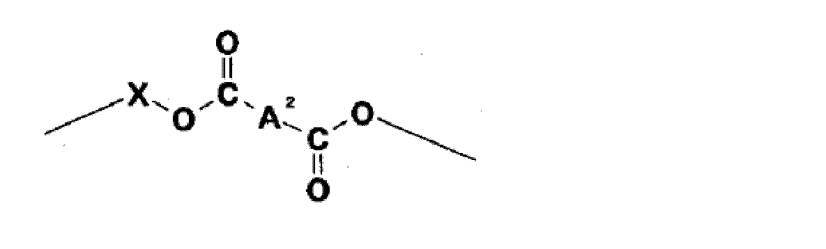
で示される基を繰り返し単位として有するアリルエステル樹脂組成物が好ましい。
フルオロメチル(メタ)アクリレート及びクロロメチル(メタ)アクリレート等のハロアルキル(メタ)アクリレート、
さらに、グリシジル(メタ)アクリレート、アルキルアミノ(メタ)アクリレート、及びα-シアノアクリル酸エステル;
エチレングリコールジ(メタ)アクリレート、ジエチレングリコールジ(メタ)アクリレート、トリエチレングリコールジ(メタ)アクリレート、テトラエチレングリコールジ(メタ)アクリレート、トリプロピレングリコールジ(メタ)アクリレート、1,3-ブチレングリコールジ(メタ)アクリレート、1,4-ブタンジオールジ(メタ)アクリレート、1,5-ペンタジオールジ(メタ)アクリレート、1,6-ヘキサジオールジ(メタ)アクリレート、ネオペンチルグリコールジ(メタ)アクリレート、オリゴエステルジ(メタ)アクリレート、ポリブタジエンジ(メタ)アクリレート、2,2-ビス(4-(メタ)アクリロイルオキシフェニル)プロパン及び2,2-ビス(4-ω-(メタ)アクリロイルオキシピリエトキシ)フェニル)プロパン等のジ(メタ)アクリレート、トリメチロールプロパントリ(メタ)アクリレート、ペンタエリスリトールトリ(メタ)アクリレート、ペンタエリスリトールテトラ(メタ)アクリレート、ペンタエリスリトールのエチレンオキサイド付加物のテトラ(メタ)アクリレート、ジペンタエリスリトールヘキサ(メタ)アクリレート等が挙げられ、中でもトリメチロールプロパントリ(メタ)アクリレートが好ましい。
光開始剤としては特に制限はなく、一般に重合性樹脂の光開始剤として用いられているものを用いることができる。その具体例としては、2,2-ジメトキシ-1,2-ジフェニルエタン-1-オン、1-ヒドロキシシクロヘキシルフェニルケトン、ベンゾフェノン、2-メチル-1-(4-メチルチオフェニル)-2-モルホリノプロパン-1、2-ベンジル-2-ジメチルアミノ-1-(4-モルホリノフェニル)-ブタノン-1、2-ヒドロキシ-2-メチル-1-フェニルプロパン-1-オン及び2,4,6-トリメチルベンゾイルジフェニルホスフィンオキサイド等が挙げられる。
これらは1種を単独で用いてもよいし、2種以上を混合ないし組み合わせて用いてもよい。
実施例及び比較例に記載のフィルムの全光線透過率、ヘーズ及び複屈折は以下の方法により測定した。
[全光線透過率]
全光線透過率は、東京電色社製全自動ヘーズメーターTC-H3DPKを使用し、JIS K-7361-1に準拠して測定した。
[ヘーズ]
ヘーズ値は、東京電色社製全自動ヘーズメーターTC-H3DPKを使用し、JIS K-7136に準拠して測定した。
[複屈折]
複屈折は、大塚電子社製RETS-1000を使用し、波長589nmにおける面内複屈折Reの測定を行なった。
撹拌機、還流冷却管、気体導入管及び温度計のついた容量1Lの4つ口フラスコに、1,4-シクロヘキサンジカルボン酸ジアリル750g(2.98mol)、トリメチロールプロパン100g(0.75mol)及びジブチル錫オキサイド0.70gを仕込み、窒素気流下、180℃で生成してくるアルコール(アリルアルコール)を留去しながら加熱した。留去したアルコールが約75gになったところで反応系内を徐々に、約4時間かけて6.6kPaまで減圧し、アルコールの留出速度を速めた。留出液が殆ど出なくなったところで反応系内を0.5kPaに減圧し、さらに1時間反応させた後反応物を冷却した。これにより得られた反応物を「アリルエステル樹脂」とする。
撹拌機、還流冷却管、気体導入管及び温度計のついた容量1Lの4つ口フラスコに、カプロラクトン変性2-ヒドロキシエチルアクリレート(ダイセル化学社製:プラクセルFA2D)を344g(1mol)、無水フタル酸を148g(1mol)、トリフェニルホスフィンを1.5g、p-メトキシフェノール0.15gを加え、空気をバブリングしながら撹拌し90℃に昇温して90分反応させ酸価が概ね109mgKOH/gとなったことを確認して1段目の反応を終了した。
次いで、ビスフェノールA型エポキシ樹脂(旭化成社製:AER-2603、エポキシ当量=185)を185g(0.5mol)、トリフェニルホスフィンを0.7g、p-メトキシフェノール0.07gを加え120℃に昇温して酸価が5mgKOH/g以下になるまで反応を行なった。これにより得られた反応物を「アクリレートオリゴマー」とする。
アリルエステル樹脂80質量部、アクリレートオリゴマー10質量部、トリメチロールプロパントリアクリレート(新中村化学工業社製、「NKエステルA-TMPT」)10質量部、光開始剤(チバ・スペシャルティ・ケミカルズ社製、「DAROCUR MBF」)1.5質量部、熱開始剤(日本油脂株式会社製、「パーヘキシルI」)1質量部からなり、粘度(25℃でB型粘度計にてNo.3ローターを使用して測定)が1800mPa・sである硬化性樹脂組成物(R1)を調製した。この硬化性樹脂組成物をナイフコーターにてPETフィルム(厚さ50μm)上に厚みが300μmの厚みになるように塗布して硬化性樹脂層を形成した。さらにカバーフィルムとしてPETフィルム(厚さ50μm)を硬化性樹脂層上にラミネートした後UV照射量600mJ/cm2にて硬化(300mJ/cm2×2/両面より照射)させ、ゲル分率(硬化により得られたフィルム約1gを精秤し、3時間アセトン還流を行なった後のフィルム質量の抽出前質量に対する割合)が58%である硬化性フィルム(F1)を得た。このような積層体を2つ用意した。
次いで、一方の積層体の片面のPETフィルムを剥離した硬化フィルム(F1)面上に硬化性樹脂組成物(R1)を200μmの厚みになるように塗布して硬化性樹脂層を形成し、さらに他方の積層体の片面のPETフィルムを剥離した硬化フィルム(F1)面を硬化性樹脂層上にラミネートした後UV照射量600mJ/cm2にて硬化(300mJ/cm2×2/両面より照射)させ、硬化フィルム(F2)とし、さらにオーブンにて160℃、1時間加熱処理により完全に硬化させ、基材PETフィルムを剥離し概ね100mm×150mm形状の厚み約800μmの硬化フィルム(F3)を得た。硬化フィルムの厚みは株式会社ミツトヨ製デジタルマイクロメーター(MDC-25MJ)を用いて4隅及び中央の5点にて測定し、その平均値として求めた。得られた硬化フィルム(F3)を55mm角の形状に切り出し、これを用いて前述の測定方法に基づき全光線透過率、ヘーズ、複屈折Reを測定した結果、全光線透過率91.8%、ヘーズ0.8%、複屈折Re2.7nmであった。
硬化性樹脂組成物(R1)をアリルエステル樹脂80質量部、トリメチロールプロパントリアクリレート(新中村化学工業社製、「NKエステルA-TMPT」)20質量部、光開始剤(チバ・スペシャルティ・ケミカルズ社製、「DAROCUR MBF」)1.5質量部、熱開始剤(日本油脂株式会社製、「パーヘキシルI」)1質量部からなり、粘度(25℃でB型粘度計にて測定)が2500mPa・sである硬化性樹脂組成物(R2)に変更した以外は実施例1と同様にしてゲル分率49%である厚み約800μmの硬化フィルム(F4)を得た。得られた硬化フィルム(F4)は全光線透過率92.1%、ヘーズ0.7%、複屈折Re2.3nmであった。
硬化フィルム(F1)に塗布する硬化性樹脂組成物を硬化性樹脂組成物(R2)に変更したこと以外は実施例1と同様にして厚み約800μmの硬化フィルム(F5)を得た。得られた硬化フィルム(F5)は全光線透過率92.0%、ヘーズ0.8%、複屈折Re2.2nmであった。
硬化性樹脂組成物(R1)をナイフコーターにてPETフィルム(厚さ50μm)上に厚みが約800μmになるように塗布して硬化性樹脂層を形成した。さらにカバーフィルムとして前記と同一のPETフィルムを硬化性樹脂層上にラミネートした後UV照射量1000mJ/cm2にて硬化(500mJ/cm2×2/両面より照射)したところ歪みが生じてしまい光学特性が測定可能な平滑なフィルムを得ることができなかった。
Claims (13)
- 第1の基材表面に硬化性樹脂組成物(A)を塗布して第1の硬化性樹脂層を形成し、前記第1の硬化性樹脂層にエネルギー線を照射して硬化フィルム(I)を形成した第1の積層体を得る第1の工程と、第2の基材表面に硬化性樹脂組成物(B)を塗布して第2の硬化性樹脂層を形成し、前記第2の硬化性樹脂層にエネルギー線を照射して硬化フィルム(II)を形成した第2の積層体を得る第2の工程と、前記第1の積層体の硬化フィルム(I)と前記第2の積層体の硬化フィルム(II)とを硬化性樹脂組成物(C)よりなる第3の硬化性樹脂層を介して接合した後エネルギー線を照射して第3の硬化性樹脂層を硬化させることにより第3の積層体を得る第3の工程と、前記第3の積層体から第1の基材及び第2の基材を剥離し、前記硬化フィルム(I)と硬化フィルム(II)との積層硬化フィルム(III)を得る第4の工程とを有することを特徴とする硬化フィルムの製造方法。
- さらに、前記第1及び/または第2の工程において前記第1及び/または第2の硬化性樹脂層にエネルギー線を照射する前に前記第1及び/または第2の硬化性樹脂層の表面にカバーフィルムを貼付する工程を含み、かつ前記第3の工程において硬化性樹脂組成物(C)を塗布する前に前記カバーフィルムを剥離する工程を含む請求項1に記載の硬化フィルムの製造方法。
- 前記第3の工程における硬化フィルム(I)と硬化フィルム(II)の第3の硬化性樹脂層を介した接合が、前記硬化フィルム(I)上に硬化性樹脂組成物(C)を塗布して第3の硬化性樹脂層を形成し、前記第3の硬化性樹脂層に前記硬化フィルム(II)を張り合わせた後エネルギー線を照射して第3の硬化性樹脂層を硬化させる工程よりなる請求項1または2に記載の硬化フィルムの製造方法。
- さらに、前記第3の工程においてエネルギー線を照射後に加熱処理する工程を含む請求項1~3のいずれかに記載の硬化フィルムの製造方法。
- 前記第4の工程前に前記第3の積層体をレーザーにより所望の寸法に切断する工程を有する請求項1~4のいずれかに記載の硬化フィルムの製造方法。
- 前記硬化フィルム(I)及び(II)が半硬化フィルムである請求項1~5のいずれかに記載の硬化フィルムの製造方法。
- 前記硬化フィルム(I)及び(II)が同一組成、条件で製造された同一の膜厚である請求項1~6のいずれかに記載の硬化フィルムの製造方法。
- 前記積層硬化フィルム(III)の厚みが0.5~1.5mmである請求項1~7のいずれかに記載の硬化フィルムの製造方法。
- 前記硬化性樹脂組成物(A)、(B)、及び(C)の組成が同一である請求項1~8のいずれかに記載の硬化フィルムの製造方法。
- 前記硬化性樹脂組成物(A)、(B)、及び(C)が、アリルエステル樹脂及び光開始剤を含む請求項1~9のいずれかに記載の硬化フィルムの製造方法。
- 前記硬化性樹脂組成物(A)、(B)、及び(C)がさらに熱開始剤を含む請求項10に記載の硬化フィルムの製造方法。
- 前記硬化性樹脂組成物(A)、(B)、及び(C)の25℃での粘度がそれぞれ100~10000mPa・sである請求項1~11のいずれかに記載の硬化フィルムの製造方法。
- 請求項1~12のいずれかの製造方法により製造された硬化フィルム。
Priority Applications (2)
| Application Number | Priority Date | Filing Date | Title |
|---|---|---|---|
| KR1020137012428A KR20130085419A (ko) | 2010-12-24 | 2011-12-22 | 경화 필름의 제조 방법 및 경화 필름 |
| JP2012549865A JPWO2012086742A1 (ja) | 2010-12-24 | 2011-12-22 | 硬化フィルムの製造方法及び硬化フィルム |
Applications Claiming Priority (2)
| Application Number | Priority Date | Filing Date | Title |
|---|---|---|---|
| JP2010287903 | 2010-12-24 | ||
| JP2010-287903 | 2010-12-24 |
Publications (1)
| Publication Number | Publication Date |
|---|---|
| WO2012086742A1 true WO2012086742A1 (ja) | 2012-06-28 |
Family
ID=46314009
Family Applications (1)
| Application Number | Title | Priority Date | Filing Date |
|---|---|---|---|
| PCT/JP2011/079771 Ceased WO2012086742A1 (ja) | 2010-12-24 | 2011-12-22 | 硬化フィルムの製造方法及び硬化フィルム |
Country Status (4)
| Country | Link |
|---|---|
| JP (1) | JPWO2012086742A1 (ja) |
| KR (1) | KR20130085419A (ja) |
| TW (1) | TW201300240A (ja) |
| WO (1) | WO2012086742A1 (ja) |
Cited By (3)
| Publication number | Priority date | Publication date | Assignee | Title |
|---|---|---|---|---|
| KR20150120472A (ko) * | 2013-02-28 | 2015-10-27 | 쇼와 덴코 가부시키가이샤 | 경화성 조성물, 투명 내열 재료 및 그 용도 |
| KR20150143823A (ko) * | 2013-06-25 | 2015-12-23 | 쇼와 덴코 가부시키가이샤 | 광경화성 수지 필름의 제조 장치 및 제조 방법 |
| WO2022064584A1 (ja) * | 2020-09-24 | 2022-03-31 | シャープ株式会社 | 表示素子 |
Families Citing this family (1)
| Publication number | Priority date | Publication date | Assignee | Title |
|---|---|---|---|---|
| EP3067124B1 (en) | 2013-11-06 | 2019-12-25 | Sekisui Chemical Co., Ltd. | Method for manufacturing cured film, method for manufacturing electronic component, and electronic component |
Citations (3)
| Publication number | Priority date | Publication date | Assignee | Title |
|---|---|---|---|---|
| JPH0664106A (ja) * | 1992-08-18 | 1994-03-08 | Mitsubishi Paper Mills Ltd | 工程用剥離シート及びその製造方法 |
| JPH082619B2 (ja) * | 1987-09-22 | 1996-01-17 | 三菱製紙株式会社 | 剥離用シート |
| JP2009126040A (ja) * | 2007-11-22 | 2009-06-11 | Nippon Steel Chem Co Ltd | 透明積層体フィルムの製造方法 |
-
2011
- 2011-12-22 WO PCT/JP2011/079771 patent/WO2012086742A1/ja not_active Ceased
- 2011-12-22 KR KR1020137012428A patent/KR20130085419A/ko not_active Ceased
- 2011-12-22 JP JP2012549865A patent/JPWO2012086742A1/ja active Pending
- 2011-12-22 TW TW100148044A patent/TW201300240A/zh unknown
Patent Citations (3)
| Publication number | Priority date | Publication date | Assignee | Title |
|---|---|---|---|---|
| JPH082619B2 (ja) * | 1987-09-22 | 1996-01-17 | 三菱製紙株式会社 | 剥離用シート |
| JPH0664106A (ja) * | 1992-08-18 | 1994-03-08 | Mitsubishi Paper Mills Ltd | 工程用剥離シート及びその製造方法 |
| JP2009126040A (ja) * | 2007-11-22 | 2009-06-11 | Nippon Steel Chem Co Ltd | 透明積層体フィルムの製造方法 |
Cited By (8)
| Publication number | Priority date | Publication date | Assignee | Title |
|---|---|---|---|---|
| KR20150120472A (ko) * | 2013-02-28 | 2015-10-27 | 쇼와 덴코 가부시키가이샤 | 경화성 조성물, 투명 내열 재료 및 그 용도 |
| KR101715672B1 (ko) * | 2013-02-28 | 2017-03-13 | 쇼와 덴코 가부시키가이샤 | 경화성 조성물, 투명 내열 재료 및 그 용도 |
| KR20150143823A (ko) * | 2013-06-25 | 2015-12-23 | 쇼와 덴코 가부시키가이샤 | 광경화성 수지 필름의 제조 장치 및 제조 방법 |
| JPWO2014208468A1 (ja) * | 2013-06-25 | 2017-02-23 | 昭和電工株式会社 | 光硬化性樹脂フィルムの製造装置および製造方法 |
| KR101990181B1 (ko) * | 2013-06-25 | 2019-06-17 | 쇼와 덴코 가부시키가이샤 | 광경화성 수지 필름의 제조 장치 및 제조 방법 |
| WO2022064584A1 (ja) * | 2020-09-24 | 2022-03-31 | シャープ株式会社 | 表示素子 |
| JPWO2022064584A1 (ja) * | 2020-09-24 | 2022-03-31 | ||
| JP7352749B2 (ja) | 2020-09-24 | 2023-09-28 | シャープ株式会社 | 表示素子 |
Also Published As
| Publication number | Publication date |
|---|---|
| JPWO2012086742A1 (ja) | 2014-06-05 |
| TW201300240A (zh) | 2013-01-01 |
| KR20130085419A (ko) | 2013-07-29 |
Similar Documents
| Publication | Publication Date | Title |
|---|---|---|
| KR102159761B1 (ko) | 접착제 조성물, 편광판용 접착제 조성물, 편광판용 접착제, 및 이를 사용하여 이루어진 편광판 | |
| CN105026444B (zh) | 固化性组合物、透明耐热材料及其用途 | |
| JP5186556B2 (ja) | 硬化フィルム及びその製造方法 | |
| JP6159328B2 (ja) | 硬化樹脂成形品の製造方法 | |
| WO2012086742A1 (ja) | 硬化フィルムの製造方法及び硬化フィルム | |
| JP5090040B2 (ja) | 透明導電性基板 | |
| JP6755184B2 (ja) | 光制御パネル及び光結像装置 | |
| JP5057809B2 (ja) | 樹脂基板の連続的製造方法 | |
| JP2018128570A (ja) | 光制御パネルおよび光学結像装置ならびに光制御パネルの製造方法 | |
| JP6524999B2 (ja) | 樹脂フィルム又はシート形成用光硬化型組成物 | |
| JP2013060587A (ja) | 硬化性樹脂組成物、硬化物及び光学部材 | |
| JP2018072644A (ja) | 光学結像装置およびその製造方法 | |
| JP2017043702A (ja) | 硬化性樹脂組成物、硬化物、光学部材、レンズ及びカメラモジュール | |
| JP2008256957A (ja) | 粘着剤層付き光学積層体 | |
| EP2004734B1 (en) | Transparent conductive substrate | |
| JP2018151425A (ja) | 光制御パネルおよび光学結像装置ならびに光制御パネルの製造方法 | |
| JP2003292545A (ja) | 重合性組成物及び硬化体 | |
| JP5186144B2 (ja) | 透明反射防止板 | |
| KR20110110229A (ko) | 투명 복합 재료 | |
| CN101415554A (zh) | 树脂基板的连续制造方法和树脂基板 | |
| JP2015232059A (ja) | 偏光板用接着剤組成物、偏光板用接着剤、およびそれを用いてなる偏光板 | |
| JP2012137726A (ja) | 画像表示装置及び画像表示装置の製造方法 | |
| JP2015101598A (ja) | アリルエステル樹脂組成物の硬化物の色調改善方法 | |
| JP2016128231A (ja) | 金属膜を有する樹脂シートの製造方法 |
Legal Events
| Date | Code | Title | Description |
|---|---|---|---|
| 121 | Ep: the epo has been informed by wipo that ep was designated in this application |
Ref document number: 11850163 Country of ref document: EP Kind code of ref document: A1 |
|
| ENP | Entry into the national phase |
Ref document number: 2012549865 Country of ref document: JP Kind code of ref document: A |
|
| ENP | Entry into the national phase |
Ref document number: 20137012428 Country of ref document: KR Kind code of ref document: A |
|
| NENP | Non-entry into the national phase |
Ref country code: DE |
|
| 122 | Ep: pct application non-entry in european phase |
Ref document number: 11850163 Country of ref document: EP Kind code of ref document: A1 |