WO2012081228A1 - 流体制御弁 - Google Patents
流体制御弁 Download PDFInfo
- Publication number
- WO2012081228A1 WO2012081228A1 PCT/JP2011/006939 JP2011006939W WO2012081228A1 WO 2012081228 A1 WO2012081228 A1 WO 2012081228A1 JP 2011006939 W JP2011006939 W JP 2011006939W WO 2012081228 A1 WO2012081228 A1 WO 2012081228A1
- Authority
- WO
- WIPO (PCT)
- Prior art keywords
- light
- valve body
- fluid control
- control valve
- light emitting
- Prior art date
Links
- 239000012530 fluid Substances 0.000 title claims abstract description 110
- 238000000034 method Methods 0.000 claims description 34
- 230000000903 blocking effect Effects 0.000 abstract description 3
- 230000004048 modification Effects 0.000 description 44
- 238000012986 modification Methods 0.000 description 44
- 238000001514 detection method Methods 0.000 description 15
- 238000010586 diagram Methods 0.000 description 14
- 238000006243 chemical reaction Methods 0.000 description 2
- 230000000694 effects Effects 0.000 description 2
- 239000000463 material Substances 0.000 description 2
- 230000002093 peripheral effect Effects 0.000 description 2
- 230000007423 decrease Effects 0.000 description 1
- 230000005284 excitation Effects 0.000 description 1
- 238000004519 manufacturing process Methods 0.000 description 1
- 230000003287 optical effect Effects 0.000 description 1
- 238000005192 partition Methods 0.000 description 1
- 239000004065 semiconductor Substances 0.000 description 1
Images


Classifications
-
- G—PHYSICS
- G05—CONTROLLING; REGULATING
- G05D—SYSTEMS FOR CONTROLLING OR REGULATING NON-ELECTRIC VARIABLES
- G05D7/00—Control of flow
- G05D7/06—Control of flow characterised by the use of electric means
- G05D7/0617—Control of flow characterised by the use of electric means specially adapted for fluid materials
- G05D7/0629—Control of flow characterised by the use of electric means specially adapted for fluid materials characterised by the type of regulator means
- G05D7/0635—Control of flow characterised by the use of electric means specially adapted for fluid materials characterised by the type of regulator means by action on throttling means
-
- F—MECHANICAL ENGINEERING; LIGHTING; HEATING; WEAPONS; BLASTING
- F16—ENGINEERING ELEMENTS AND UNITS; GENERAL MEASURES FOR PRODUCING AND MAINTAINING EFFECTIVE FUNCTIONING OF MACHINES OR INSTALLATIONS; THERMAL INSULATION IN GENERAL
- F16K—VALVES; TAPS; COCKS; ACTUATING-FLOATS; DEVICES FOR VENTING OR AERATING
- F16K37/00—Special means in or on valves or other cut-off apparatus for indicating or recording operation thereof, or for enabling an alarm to be given
- F16K37/0058—Optical means, e.g. light transmission, observation ports
-
- G—PHYSICS
- G01—MEASURING; TESTING
- G01B—MEASURING LENGTH, THICKNESS OR SIMILAR LINEAR DIMENSIONS; MEASURING ANGLES; MEASURING AREAS; MEASURING IRREGULARITIES OF SURFACES OR CONTOURS
- G01B11/00—Measuring arrangements characterised by the use of optical techniques
- G01B11/14—Measuring arrangements characterised by the use of optical techniques for measuring distance or clearance between spaced objects or spaced apertures
-
- G—PHYSICS
- G01—MEASURING; TESTING
- G01D—MEASURING NOT SPECIALLY ADAPTED FOR A SPECIFIC VARIABLE; ARRANGEMENTS FOR MEASURING TWO OR MORE VARIABLES NOT COVERED IN A SINGLE OTHER SUBCLASS; TARIFF METERING APPARATUS; MEASURING OR TESTING NOT OTHERWISE PROVIDED FOR
- G01D5/00—Mechanical means for transferring the output of a sensing member; Means for converting the output of a sensing member to another variable where the form or nature of the sensing member does not constrain the means for converting; Transducers not specially adapted for a specific variable
- G01D5/26—Mechanical means for transferring the output of a sensing member; Means for converting the output of a sensing member to another variable where the form or nature of the sensing member does not constrain the means for converting; Transducers not specially adapted for a specific variable characterised by optical transfer means, i.e. using infrared, visible, or ultraviolet light
- G01D5/32—Mechanical means for transferring the output of a sensing member; Means for converting the output of a sensing member to another variable where the form or nature of the sensing member does not constrain the means for converting; Transducers not specially adapted for a specific variable characterised by optical transfer means, i.e. using infrared, visible, or ultraviolet light with attenuation or whole or partial obturation of beams of light
- G01D5/34—Mechanical means for transferring the output of a sensing member; Means for converting the output of a sensing member to another variable where the form or nature of the sensing member does not constrain the means for converting; Transducers not specially adapted for a specific variable characterised by optical transfer means, i.e. using infrared, visible, or ultraviolet light with attenuation or whole or partial obturation of beams of light the beams of light being detected by photocells
- G01D5/342—Mechanical means for transferring the output of a sensing member; Means for converting the output of a sensing member to another variable where the form or nature of the sensing member does not constrain the means for converting; Transducers not specially adapted for a specific variable characterised by optical transfer means, i.e. using infrared, visible, or ultraviolet light with attenuation or whole or partial obturation of beams of light the beams of light being detected by photocells the sensed object being the obturating part
-
- Y—GENERAL TAGGING OF NEW TECHNOLOGICAL DEVELOPMENTS; GENERAL TAGGING OF CROSS-SECTIONAL TECHNOLOGIES SPANNING OVER SEVERAL SECTIONS OF THE IPC; TECHNICAL SUBJECTS COVERED BY FORMER USPC CROSS-REFERENCE ART COLLECTIONS [XRACs] AND DIGESTS
- Y10—TECHNICAL SUBJECTS COVERED BY FORMER USPC
- Y10T—TECHNICAL SUBJECTS COVERED BY FORMER US CLASSIFICATION
- Y10T137/00—Fluid handling
- Y10T137/0318—Processes
Definitions
- the present invention relates to a fluid control valve. More specifically, the present invention relates to a fluid control valve capable of detecting the position of a valve body.
- Patent Document 1 discloses a fluid control valve.
- the fluid control valve includes a stator having a coil, a rotor that is rotated by excitation by energization of the coil, a rotating shaft of the rotor, a partition wall provided between the stator and the rotor, a rotational position detecting unit of the rotor,
- the converter includes a conversion unit that is locked to the rotation shaft of the rotor and converts the rotation of the rotor into a linear motion, a valve body that is locked to the conversion unit and opens and closes the flow path, and a position detection unit of the valve body.
- the valve body position detection means a configuration using magnetic detection means is disclosed.
- An object of the present invention is to provide a fluid control valve capable of detecting the position of a valve body by an unprecedented method.
- the conventional configuration using the magnetic detection unit as the position detection unit of the valve body may not be used depending on the flow path in which the valve is provided or the peripheral device configuration. For this reason, the present inventors have intensively studied to provide a fluid control valve capable of detecting the position of the valve body by an unprecedented method.
- the inventors of the present invention have a fluid control valve that includes a light emitting unit and a light receiving unit that receives light emitted from the light emitting unit, and the degree of light that reaches the light receiving unit from the light emitting unit is blocked as the valve body moves. It has been found that the position of the valve body can be detected.
- the fluid control valve of the present invention includes a light emitting unit that emits light, a light receiving unit that is provided to face the light emitting unit and detects the amount of light received from the light emitting unit, and a valve body that opens and closes a flow path.
- the valve body or the light shielding portion fixed to the valve body moves in a direction crossing between the light emitting portion and the light receiving portion as the flow path is opened and closed, and the light receiving portion is the light emitting portion.
- the amount of light received from the sensor is changed according to the position of the valve body, and the position of the valve body is detected based on the amount of light received by the light receiving unit.
- the fluid control valve control method of the present invention is a fluid control valve control method using the fluid control valve, wherein the light emitting unit emits light and the light receiving unit receives light based on the amount of light received.
- a first step for detecting the position a second step for cutting off the power supply to the light emitting section after the first step, and a power supply for the actuator connected to the valve body after the second step.
- Such a configuration can further reduce power consumption associated with valve control.
- the valve body includes the light shielding portion formed so as to protrude along a direction in which the valve body moves, and the light shielding portion is configured to open and close the flow path.
- the amount of light received by the light receiving unit from the light emitting unit is changed according to the position of the valve body, and based on the amount of light received by the light receiving unit, The position may be detected.
- the fluid control valve control method further includes a fifth step of driving the valve body by sending a pulse for closing the flow path to the step motor connected to the valve body, and after the fifth step.
- the sixth step of detecting the position of the valve element based on the amount of light received by the light receiving unit, and whether the position of the valve element detected in the sixth step is a position where the flow path is closed
- a pulse for lowering the pulse frequency than the pulse and closing the flow path again is given to the step motor.
- a ninth step of driving the valve body is
- the amount of light received by the light receiving unit from the light emitting unit depends on the position of the valve body by having a tapered shape in which the light shielding unit is thinned along a moving direction of the valve body.
- the position of the valve element may be continuously detected from fully open to fully closed based on the amount of light received by the light receiving unit.
- the light shielding unit includes a plurality of holes arranged in a direction in which the valve body moves, so that the amount of light received from the light emitting unit by the light receiving unit alternately has a maximum value and a minimum value.
- the position of the valve element may be continuously detected from fully open to fully closed based on the amount of light received by the light receiving unit.
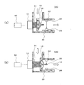
- FIG. 1 is a diagram illustrating an example of a schematic configuration of a fluid control valve according to an example of the first embodiment, in which FIG. 1A illustrates an open state, and FIG. 1B illustrates a closed state. It is.
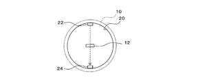
- FIG. 2 is a plan view of the fluid control valve according to the example of the first embodiment when viewed from the axial direction of the flow path.
- FIG. 3 is a diagram illustrating an example of a schematic configuration of a fluid control valve according to a first modification of the first embodiment.
- FIG. 3A is a diagram illustrating an open state
- FIG. 3B is a diagram illustrating a closed state.
- FIG. FIG. 4 is a diagram illustrating an example of a schematic configuration of a fluid control valve according to a second modification of the first embodiment.
- FIG. 4A is a diagram illustrating an open state
- FIG. 4B is a diagram illustrating a closed state
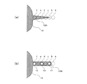
- FIG. Fig.5 (a) is a figure which shows an example of schematic structure of the light-shielding part with which the fluid control valve concerning the 3rd modification of 1st Embodiment is provided
- FIG.5 (b) is 4th of 1st Embodiment. It is a figure which shows an example of schematic structure of the light-shielding part with which the fluid control valve concerning a modification is provided.
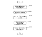
- FIG. 6 is a flowchart illustrating an example of a control method of the fluid control valve according to the second embodiment.
- FIG. 7 is a flowchart illustrating an example of a control method of the fluid control valve according to the third embodiment.
- FIG. 8 is a flowchart illustrating an example of a control method of the fluid control valve according to the modification of the third embodiment.
- FIG. 1 is a diagram illustrating an example of a schematic configuration of a fluid control valve according to an example of the first embodiment, in which FIG. 1A illustrates an open state, and FIG. 1B illustrates a closed state. It is.
- FIG. 2 is a plan view of the fluid control valve according to the example of the first embodiment when viewed from the axial direction of the flow path.
- the fluid control valve of the first embodiment will be described with reference to FIGS. 1 and 2.
- the fluid control valve includes a light emitting unit 22 that emits light and a light receiving unit that is provided to face the light emitting unit 22 and detects the amount of light received from the light emitting unit 22. 24 and the valve body 10 that opens and closes the flow path 20, and the light shielding section 12 fixed to the valve body 10 or the valve body 10 is disposed between the light emitting section 22 and the light receiving section 24 as the flow path 20 is opened and closed. , The amount of light received by the light receiving unit 24 from the light emitting unit 22 is changed according to the position of the valve body 10, and the position of the valve body 10 is detected based on the amount of light received by the light receiving unit 24. .
- the valve element 10 can have any shape as long as it can open and close the flow path 20. Any material can be used as long as it is a material used for a fluid valve.
- the light shielding part 12 may be omitted (see the first modification).
- a light emitting element such as a light emitting diode or a semiconductor laser can be used for the light emitting unit 22.
- an optical sensor such as a photoresistor, a photodiode, or a phototube can be used.
- the light emitting unit 22 and the light receiving unit 24 may use commercially available photo interrupters (see the second modification).
- the open state illustrated in FIG. 1A the light emitted from the light emitting unit 22 reaches the light receiving unit 24 without being blocked by the light blocking unit 12 or the valve body 10.
- the closed state illustrated in FIG. 1B the light emitted from the light emitting unit 22 is blocked by the light blocking unit 12 and does not reach the light receiving unit 24.
- the fluid control valve can detect the position of the valve body 10 based on the difference in the light shielding amount (difference in the amount of light received by the light receiving unit 24). Note that it is not necessary to block all of the light in the closed state, and part of it may pass. Or after adjusting the shape of the light-shielding part 12 or the valve body 10, for example, it is good also as a structure which light is interrupted
- Information on the amount of light detected by the light receiving unit 24 is sent to some controller for processing, but the subject that performs the processing is not particularly limited.
- the controller 50 may also have a function of processing such information.
- a controller (position detection controller) for detecting the position of the valve body 10 may be provided separately from the controller 50.
- Control may be performed in which power is supplied to the light emitting unit 22 to cause the light emitting unit 22 to emit light, or power supply to the light emitting unit 22 is cut off to stop light emission of the light emitting unit 22.
- Such control may also be performed by the controller 50 when a controller 50 for controlling the actuator 16 of the valve body 10 is provided as illustrated in FIG.
- a controller (light emission controller) for controlling the light emitting unit 22 may be provided separately from the controller 50.
- the controller 50 that controls the actuator 16 of the valve body 10 may be provided as illustrated in FIG. 1A, the controller 50, the position detection controller, and the light emission controller may be used in any combination and in common.
- a single controller may be used.
- the controller may be provided separately from the fluid control valve.
- the controller may be, for example, a centralized control type controller having a single CPU, or a distributed control type controller having a plurality of CPUs.
- the fluid control valve of the present embodiment may be configured to be able to detect the position of the valve body 10 based on the amount of light received by the light receiving unit 24, and the fluid control valve does not necessarily include a controller. .
- the drive shaft 14 that connects the actuator 16 and the valve body 10 illustrated in FIG. 1A is not essential.
- the fluid control valve is provided at the bent portion of the flow path, but the fluid control valve may be provided in the middle of the linear flow path, for example.
- the fluid control valve 100 is provided in a portion where the flow path 20 is bent.
- a fluid preferably gas flows in the flow path 20 in the direction of the white arrow in FIG.
- the fluid control valve 100 includes a valve body 10 having a convex portion that swells in a central portion facing the flow path, and a light shielding portion 12 that is fixed to the valve body 10 so as to protrude from the convex portion toward the flow path.
- a drive shaft 14 that holds the valve body 10 and drives the valve body 10, an actuator 16 that is coupled to the drive shaft 14, and a controller 50 that is electrically connected to the actuator 16.
- a light emitting unit 22 and a light receiving unit 24 are provided on the inner wall of the flow path 20 on the downstream side of the valve body 10 so as to face each other and so that a straight line connecting both passes through the central axis of the flow path 20. ing.
- the controller 50 is also connected to the light emitting unit 22 and the light receiving unit 24, and the controller 50 executes the light emission control of the light emitting unit 22 and the position detection of the valve body 10 based on the amount of light received by the light receiving unit 24.
- the shape of the cross section cut by a plane perpendicular to the axial direction of the flow path 20 is circular.
- the thickness in the direction of the straight line connecting the light emitting part 22 and the light receiving part 24 is shorter than the width perpendicular to the straight line.
- a step is formed on the downstream side of the valve body 10 so that the inner diameter of the flow path 20 is narrowed.
- the diameter of the valve body 10 is that of the narrower flow path 20. It is larger than the diameter.
- the valve is closed by the peripheral edge of the valve body 10 coming into contact with the step.
- the actuator 16 is a stepping motor that is digitally controlled by the controller 50.
- the drive shaft 14 is a ball screw, and a thread groove is formed in a portion where the drive shaft 14 penetrates the flow path 20. With this configuration, when the actuator 16 rotates clockwise or counterclockwise based on the control of the controller 50, the drive shaft 14 and the valve body 10 move forward or left in FIG. 1 in accordance with the direction and amount of rotation. fall back.
- the positional relationship between the light emitting unit 22 and the light receiving unit 24 and the light shielding unit 12 is such that light from the light emitting unit 22 is shielded in a state where the valve body 10 completely opens the flow path 20 (fully opened state: FIG. 1A).
- the valve body 10 if the amount of light reaching the light receiving unit 24 from the light emitting unit 22 reaches the maximum value, the valve body 10 completely opens the flow path 20 (the position of the valve body 10 in FIG. 1A). ). Conversely, if the amount of light reaching the light receiving unit 24 from the light emitting unit 22 is zero, it is determined that the valve body 10 is in a position where the flow path 20 is completely closed (the position of the valve body 10 in FIG. 1B). it can.
- the fluid control valve 100 can detect the position of the valve body in this manner.
- the result of the position detection of the valve body 10 may be used for controlling the actuator 16 as in the second and third embodiments, or may be output by a separate output unit regardless of the control of the actuator 16. , May be confirmed by the user. That is, how the position detection result is used is not particularly limited.
- FIG. 3 is a diagram illustrating an example of a schematic configuration of a fluid control valve according to a first modification of the first embodiment.
- FIG. 3A is a diagram illustrating an open state
- FIG. 3B is a diagram illustrating a closed state.
- FIG. 3A is a diagram illustrating an open state
- FIG. 3B is a diagram illustrating a closed state.
- the fluid control valve 200 omits the light-shielding portion 12, except that the light-emitting portion 22 and the light-receiving portion 24 are moved immediately downstream of the portion where the valve body 10 closes the flow path 20. It has the same configuration as the fluid control valve 100. Therefore, about the component which is common between the fluid control valve 100 and the fluid control valve 200, the same code
- the valve body 10 itself blocks light reaching the light receiving unit 24 from the light emitting unit 22 in the fully closed state.
- the positional relationship between the light emitting unit 22 and the light receiving unit 24 and the valve body 10 is such that light from the light emitting unit 22 is in the valve body 10 in a state where the valve body 10 completely opens the flow path 20 (fully opened state: FIG. 3A).
- a state in which the valve body 10 completely closes the flow path 20 so as to reach the light receiving portion 24 without being shielded from light by the convex portion provided at the center of the center (fully closed state: FIG. 3B).
- the light from the light emitting part 22 is completely shielded by the convex part and does not reach the light receiving part 24.
- the valve body 10 when the amount of light reaching the light receiving unit 24 from the light emitting unit 22 reaches the maximum value, the valve body 10 completely opens the flow path 20 (the position of the valve body 10 in FIG. 3A). ). Conversely, if the amount of light reaching the light receiving unit 24 from the light emitting unit 22 is zero, it is determined that the valve body 10 is in a position where the flow path 20 is completely closed (the position of the valve body 10 in FIG. 3B). it can.
- the fluid control valve 200 can detect the position of the valve body in this manner.
- FIG. 4 is a diagram illustrating an example of a schematic configuration of a fluid control valve according to a second modification of the first embodiment.
- FIG. 4A is a diagram illustrating an open state
- FIG. 4B is a diagram illustrating a closed state.
- FIG. 4A is a diagram illustrating an open state
- FIG. 4B is a diagram illustrating a closed state.
- the fluid control valve 300 according to the second modified example has the same configuration as the fluid control valve 100 except that the light emitting unit 22 and the light receiving unit 24 are replaced with a general-purpose photo interrupter 21. Therefore, about the component which is common between the fluid control valve 100 and the fluid control valve 300, the same code
- the photo interrupter 21 for example, a commercially available photo interrupter can be used.
- the photo interrupter 21 includes a light emitting unit 22A and a light receiving unit 24A. Since the functions of the light emitting unit 22A and the light receiving unit 24A are the same as those of the light emitting unit 22 and the light receiving unit 24, detailed description thereof is omitted.
- the positional relationship among the light emitting unit 22A, the light receiving unit 24A, and the light shielding unit 12 is such that the light from the light emitting unit 22A is a light shielding unit in a state where the valve body 10 completely opens the flow path 20 (fully opened state: FIG. 4A). 12, the light from the light emitting part 22 ⁇ / b> A in a state where it reaches the light receiving part 24 ⁇ / b> A without being shielded by light and the valve body 10 completely closes the flow path 20 (fully closed state: FIG. 4B). Is set so that it is completely shielded by the light shielding unit 12 and does not reach the light receiving unit 24A.
- the operation in the embodiment can be applied as it is, and thus detailed description can be omitted.
- the same effect as in the embodiment can be obtained. Furthermore, in the second modified example, since a general-purpose photo interrupter can be used instead of the light emitting unit 22 and the light receiving unit 24, the manufacturing cost can be reduced.
- the above-described modification and the same control method as in the embodiment can be employed. You may combine a 2nd modification and a 1st modification.
- FIG.5 (a) is a figure which shows an example of schematic structure of the light-shielding part with which the fluid control valve concerning the 3rd modification of 1st Embodiment is provided
- FIG.5 (b) is 4th of 1st Embodiment. It is a figure which shows an example of schematic structure of the light-shielding part with which the fluid control valve concerning a modification is provided.
- the fluid control valve according to the third modification has the same configuration as the fluid control valve 100 of the embodiment except that the light shielding portion 12 is replaced with a light shielding portion 12A having a different shape. Therefore, about the component which is common between the fluid control valve and fluid control valve 100 concerning a 3rd modification, the same code
- the light shielding portion 12A has a tapered shape that becomes narrower along the direction in which the valve body 10 moves, so that the amount of light received by the light receiving portion 24 from the light emitting portion 22 is reduced.
- the position of the valve body 10 can be continuously detected from fully open to fully closed based on the amount of light received by the light receiving unit 24.
- continuous means detecting not only two states, the fully open state and the fully closed state, but also an intermediate state, and the intermediate state is detected with analog continuity.
- it may be detected digitally, that is, stepwise (stepwise).
- the detection is performed digitally, that is, stepwise (stepwise) from the viewpoint of affinity with digital control. The same applies to the fourth modification.
- the light shielding portion 12A has a tapered shape that becomes narrower toward the downstream side of the flow path.
- circles a, b, c, d, e, and f indicated by broken lines indicate the position and range of the light receiving surface of the light receiving unit 24 viewed from the light emitting unit 22 side.
- the light receiving unit 24 In the fully open state, the light receiving unit 24 is in a circular position indicated by a with respect to the valve body 10. Therefore, the amount of light received by the light receiving unit 24 is the maximum value (100%).
- the valve body 10 moves forward and the flow path 20 is closed, the position of the light receiving unit 24 with respect to the valve body 10 changes to b, c, d, e, and f.
- the position of the valve body 10 can be continuously detected based on the amount of light received by the light receiving unit 24.
- the main body that performs the detection may be the controller 50 or a controller provided separately.
- the above-described modification and the same control method as in the embodiment can be employed.
- the third modification and the second modification may be combined.
- the fluid control valve according to the fourth modification has the same configuration as that of the fluid control valve 100 of the embodiment except that the light shielding portion 12 is replaced with a light shielding portion 12B having a different shape. Therefore, about the component which is common between the fluid control valve concerning 4th modification and the fluid control valve 100, the same code
- the light-shielding part 12B has a plurality of holes 11, 13, and 15 arranged along the direction in which the valve body 10 moves, so that the light-receiving part 24 receives light from the light-emitting part 22
- the amount is configured to alternately take a maximum value and a minimum value, and based on the amount of light received by the light receiving unit 24, the position of the valve body 10 can be continuously detected from fully open to fully closed.
- the light shielding unit 12 ⁇ / b> B has the same external shape as the light shielding unit 12, but the light shielding unit 12 ⁇ / b> B passes through the light shielding unit in the direction of the straight line connecting the light emitting unit 22 and the light receiving unit 24.
- a number of holes 11, 13, 15 are formed.
- circles a, b, c, d, e, and f indicated by broken lines indicate the position and range of the light receiving surface of the light receiving unit 24 viewed from the light emitting unit 22 side.
- the light receiving unit 24 In the fully open state, the light receiving unit 24 is in a circular position indicated by a with respect to the valve body 10. Therefore, the amount of light received by the light receiving unit 24 is the maximum value (100%).
- the position of the light receiving unit 24 with respect to the valve body 10 changes to b, c, d, e, and f.
- the amount of light received by the light receiving unit 24 is, for example, 80% (maximum value), 0% (minimum value), 80% (maximum value), 0% (minimum value), 80% (maximum value).
- the position of the valve body 10 can be continuously detected by counting the number of times the amount of light increases or decreases based on the amount of light received by the light receiving unit 24 that changes in a pulse shape.
- the main body that performs the detection may be the controller 50 or a controller provided separately. Each maximum value and minimum value may be different from each other.
- the above-described modification and the same control method as in the embodiment can be employed. You may combine a 4th modification and a 2nd modification.
- the control method of the fluid control valve according to the second embodiment can be executed in any of the device configurations described in the first embodiment and its examples and modifications. Therefore, detailed description of the configuration of the fluid control valve in the second embodiment is omitted.
- the configuration of the fluid control valve is the same as that of the example of the first embodiment will be described as an example (the same applies to the third embodiment and its modifications).
- FIG. 6 is a flowchart showing an example of a control method of the fluid control valve according to the second embodiment.
- the operation shown in the flowchart is executed by the controller 50, for example, but may be executed by a controller provided separately from the controller 50, or by cooperation between the controller and the controller 50. It may be executed (the same applies to the third embodiment and its modifications).
- step S101 when execution of a program for driving the valve body 10 is started (start), power supply to the light emitting unit 22 is first started.
- the light emitting unit 22 emits light, and the position of the valve body 10 is detected based on the amount of light received by the light receiving unit 24 (step S101).
- step S102 power supply to the light emitting unit 22 is cut off (step S102), power supply to the actuator 16 is started, and the valve body 10 is driven (step S103).
- step S104 the power supply to the actuator 16 is cut off (step S104), the power supply to the light emitting unit 22 is started and the light emitting unit 22 emits light. Based on the amount of light received by the light receiving unit 24, the valve body 10 A position is detected (step S105). Thereby, the drive of the valve body 10 is completed (end).
- step S101 when the fluid control valve in the closed state is opened, it is confirmed in step S101 that the valve is in the closed state. Thereafter, the valve body 10 is driven in step S103, and finally it is confirmed in step S105 whether the valve body 10 has moved to a desired position.
- the valve body can be reliably moved to a desired position. Furthermore, unnecessary power supply to the light emitting unit 22 and the actuator 16 is not performed, and power consumption can be reduced. Note that it is not always necessary to start the light emission of the light emitting unit 22 in step S101, and the light emission of the light emitting unit 22 may already be performed in the step S101.
- FIG. 7 is a flowchart illustrating an example of a control method of the fluid control valve according to the third embodiment.
- the valve body 10 is closed (for example, FIG.
- a pulse signal (closing pulse) for moving to the position of the valve body 10 in 1 (b) is output from the controller 50 to the actuator 16 (step S201). Thereby, the valve body 10 is driven.
- step S202 the position of the valve body 10 is detected based on the amount of light received by the light receiving unit 24 (step S202). Based on the detection result, it is determined whether or not the position of the valve body 10 is in the closed position (step S203). If the determination result is yes, the closing of the fluid control valve ends (end).
- step S204 a closing pulse is output again (step S204), and the valve body 10 is driven. Then, it returns to step S202 and the position of the valve body 10 is detected again.
- the fluid control valve can be reliably closed.
- the fluid control valve control method of the third embodiment may be executed in combination with the fluid control valve control method of the second embodiment.
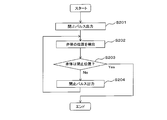
- FIG. 8 is a flowchart illustrating an example of a control method of the fluid control valve according to the modification of the third embodiment.
- the valve body 10 is first closed ( For example, a pulse signal (closing pulse) for moving to the position of the valve body 10 in FIG. 1B is output from the controller 50 to the actuator 16 (step S301). Thereby, the valve body 10 is driven.
- step S302 the position of the valve body 10 is detected based on the amount of light received by the light receiving unit 24 (step S302). Based on the detection result, it is determined whether or not the valve body 10 is in the closed position (step S303). If the determination result is yes, the closing of the fluid control valve ends (end).
- the closing frequency is output again by lowering the pulse frequency so that the torque of the pulse motor constituting the actuator 16 is improved (step S304), and the valve body 10 is Driven. Then, it returns to step S302 and the position of the valve body 10 is detected again.
- the fluid control valve can be more reliably closed.
- the fluid control valve control method according to the modification of the third embodiment may be executed in combination with the fluid control valve control method of the second embodiment.
- the fluid control valve of the present invention is useful as a fluid control valve capable of detecting the position of a valve body by an unprecedented method.
Abstract
光を発する発光部(22)と、発光部(22)に対向するように設けられ、発光部(22)から受け取る光の量を検出する受光部(24)と、流路(20)を開閉する弁体(10)とを備え、弁体(10)または弁体(10)に固定された遮光部(12)が、流路(20)の開閉に伴って発光部(22)と受光部(24)との間を横切る方向に移動し、受光部(24)が発光部(22)から受け取る光の量を弁体(10)の位置に応じて変化させ、受光部(24)が受け取る光の量に基づいて弁体(10)の位置を検出する。
Description
本発明は、流体制御弁に関する。より詳しくは、弁体の位置を検出可能な流体制御弁に関する。
特許文献1は、流体制御弁を開示する。同流体制御弁は、コイルを有するステータと、コイルへの通電による励磁により回転するロータと、ロータの回転軸と、ステータとロータの間に設けられた隔壁と、ロータの回転位置検出手段と、ロータの回転軸に係止されロータの回転を直動に変換する変換手段と、変換手段に係止され流路を開閉する弁体と、弁体の位置検出手段とを備えている。弁体の位置検出手段としては、磁気検出手段を用いた構成が開示されている。
本発明は、従来にない方法で弁体の位置を検出可能な流体制御弁を提供することを課題とする。
弁体の位置検出手段として、磁気検出手段を用いる従来の構成は、弁の設けられる流路やその周辺の装置構成などによっては利用できない場合があった。このため、本発明者らは、従来にない方法で弁体の位置を検出可能な流体制御弁を提供すべく、鋭意検討を行った。
その結果本発明者らは、発光部と、これが発する光を受光する受光部とを備える流体制御弁とし、弁体の移動に伴って発光部から受光部に届く光が遮光される程度を異ならせることにより、弁体の位置を検出することができることに気づいた。
すなわち本発明の流体制御弁は、光を発する発光部と、前記発光部に対向するように設けられ、前記発光部から受け取る光の量を検出する受光部と、流路を開閉する弁体とを備え、前記弁体または前記弁体に固定された遮光部が、前記流路の開閉に伴って前記発光部と前記受光部との間を横切る方向に移動し、前記受光部が前記発光部から受け取る光の量を前記弁体の位置に応じて変化させ、前記受光部が受け取る光の量に基づいて前記弁体の位置を検出する。
かかる構成では、従来にない方法で弁体の位置を検出可能な流体制御弁を提供することができる。
また本発明の流体制御弁の制御方法は、上記流体制御弁を用いた流体制御弁の制御方法であって、前記発光部を発光させ前記受光部が受け取る光の量に基づいて前記弁体の位置を検出する第1ステップと、前記第1ステップの後に前記発光部への電力供給を切断する第2ステップと、前記第2ステップの後に前記弁体に接続されたアクチュエータへの電力供給を開始して前記弁体を駆動する第3ステップと、前記第3ステップの後に前記アクチュエータへの電力供給を切断する第4ステップと、前記第4ステップの後に前記発光部を発光させ前記受光部が受け取る光の量に基づいて前記弁体の位置を検出する第5ステップと、を有する。
かかる構成では、さらに弁の制御に伴う電力消費を低減できる。
上記流体制御弁において、前記弁体が、前記弁体の移動する方向に沿って突出するように形成された前記遮光部を備え、前記遮光部が、前記流路の開閉に伴って前記発光部と前記受光部との間を移動し、前記受光部が前記発光部から受け取る光の量を前記弁体の位置に応じて変化させ、前記受光部が受け取る光の量に基づいて前記弁体の位置を検出してもよい。
上記流体制御弁の制御方法は、さらに、前記弁体に接続されたステップモータに対して流路を閉止するためのパルスを送り前記弁体を駆動する第5ステップと、前記第5ステップの後に前記受光部が受け取る光の量に基づいて前記弁体の位置を検出する第6ステップと、前記第6ステップで検出された前記弁体の位置が、流路が閉止されている位置であるか否かを判定する第7ステップと、前記第7ステップの判定結果がNoの場合に、前記ステップモータに対して、再度流路を閉止するためのパルスを送り前記弁体を駆動する第8ステップと、を有してもよい。
上記流体制御弁の制御方法は、さらに、前記弁体に接続されたステップモータに対して流路を閉止するためのパルスを送り前記弁体を駆動する第5ステップと、前記第5ステップの後に前記受光部が受け取る光の量に基づいて前記弁体の位置を検出する第6ステップと、前記第6ステップで検出された前記弁体の位置が、流路が閉止されている位置であるか否かを判定する第7ステップと、前記第7ステップの判定結果がNoの場合に、前記ステップモータに対して、前記パルスよりもパルスの周波数を下げて再度流路を閉止するためのパルスを送り前記弁体を駆動する第9ステップと、を有してもよい。
上記流体制御弁において、前記遮光部が前記弁体の移動する方向に沿って細くなるテーパ形状を有することにより、前記受光部が前記発光部から受け取る光の量が前記弁体の位置に応じて連続的に変化させることで、前記受光部が受け取る光の量に基づいて前記弁体の位置を全開から全閉まで連続的に検出してもよい。
上記流体制御弁において、前記遮光部が前記弁体の移動する方向に沿って並ぶ複数の穴を有することにより、前記受光部が前記発光部から受け取る光の量が極大値および極小値を交互に取り、前記受光部が受け取る光の量に基づいて前記弁体の位置を全開から全閉まで連続的に検出してもよい。
本発明の流体制御弁によれば、従来にない方法で弁体の位置を検出可能であるという効果を奏する。
(第1実施形態)
[装置構成]
図1は、第1実施形態の実施例にかかる流体制御弁の概略構成の一例を示す図であり、図1(a)は開状態を示す図、図1(b)は閉状態を示す図である。図2は、第1実施形態の実施例にかかる流体制御弁を流路の軸方向から見た平面図である。以下、図1および図2を参照しつつ、第1実施形態の流体制御弁について説明する。
[装置構成]
図1は、第1実施形態の実施例にかかる流体制御弁の概略構成の一例を示す図であり、図1(a)は開状態を示す図、図1(b)は閉状態を示す図である。図2は、第1実施形態の実施例にかかる流体制御弁を流路の軸方向から見た平面図である。以下、図1および図2を参照しつつ、第1実施形態の流体制御弁について説明する。
なお、符号は本実施形態とその実施例との対応関係をあくまで例示するために付したに過ぎず、本実施形態の流体制御弁の構成が図1に限定されるものではない。以下、他の実施形態においても同様である。
図1に例示するように、第1実施形態の流体制御弁は、光を発する発光部22と、発光部22に対向するように設けられ、発光部22から受け取る光の量を検出する受光部24と、流路20を開閉する弁体10とを備え、弁体10または弁体10に固定された遮光部12が、流路20の開閉に伴って発光部22と受光部24との間を横切る方向に移動し、受光部24が発光部22から受け取る光の量を弁体10の位置に応じて変化させ、受光部24が受け取る光の量に基づいて弁体10の位置を検出する。
かかる構成では、従来にない方法で弁体の位置を検出可能な流体制御弁を提供することができる。
弁体10は、流路20を開閉できるものであれば任意の形状とすることができる。材料も、流体弁に用いられる材料であれば適宜に採用できる。
遮光部12は省略してもよい(第1変形例を参照)。
発光部22は、例えば発光ダイオードや半導体レーザなどの発光素子を用いることができる。受光部24は、例えばフォトレジスタ、光ダイオード、光電管などの光センサを用いることができる。発光部22および受光部24は、市販のフォトインタラプタを利用してもよい(第2変形例を参照)
図1(a)に例示する開状態においては、発光部22から発せられた光が、遮光部12あるいは弁体10に遮られることなく、受光部24に到達する。一方、図1(b)に例示する閉状態においては、発光部22から発せられた光が、遮光部12に遮られ、受光部24に到達しない。流体制御弁は、かかる遮光量の違い(受光部24が受け取る光の量の違い)によって、弁体10の位置を検出することができる。なお、閉状態において光の全部が遮断される必要はなく、一部が通過してもよい。あるいは、例えば、遮光部12や弁体10の形状を調整した上で、開状態において光が遮断され、閉状態において光が遮断されない構成としてもよい。いずれにせよ、弁体10の位置の違いによって弁体10あるいは遮光部12による遮光の割合が変化するように構成されることが好ましい。必ずしも弁の全開と全閉とを検出するのではなく、その中間的な状態を検出することとしてもよい(例えば、第3変形例および第4変形例を参照)。
図1(a)に例示する開状態においては、発光部22から発せられた光が、遮光部12あるいは弁体10に遮られることなく、受光部24に到達する。一方、図1(b)に例示する閉状態においては、発光部22から発せられた光が、遮光部12に遮られ、受光部24に到達しない。流体制御弁は、かかる遮光量の違い(受光部24が受け取る光の量の違い)によって、弁体10の位置を検出することができる。なお、閉状態において光の全部が遮断される必要はなく、一部が通過してもよい。あるいは、例えば、遮光部12や弁体10の形状を調整した上で、開状態において光が遮断され、閉状態において光が遮断されない構成としてもよい。いずれにせよ、弁体10の位置の違いによって弁体10あるいは遮光部12による遮光の割合が変化するように構成されることが好ましい。必ずしも弁の全開と全閉とを検出するのではなく、その中間的な状態を検出することとしてもよい(例えば、第3変形例および第4変形例を参照)。
受光部24が検出した光の量に関する情報は、何らかの制御器に送られて処理されるが、該処理を行う主体は特に限定されない。例えば、図1(a)に例示されるように弁体10のアクチュエータ16を制御する制御器50が設けられる場合には、制御器50がかかる情報の処理を行う機能を兼ね備えていてもよい。あるいは、制御器50とは別個に、弁体10の位置を検出するための制御器(位置検出制御器)が設けられていてもよい。
発光部22に電力を供給して発光部22を発光させ、あるいは発光部22への電力供給を切断して発光部22の発光を停止させる制御が行われてもよい。かかる制御も、例えば、図1(a)に例示されるように弁体10のアクチュエータ16を制御する制御器50が設けられる場合には、制御器50により行なわれてもよい。あるいは、制御器50とは別個に、発光部22の制御を行なうための制御器(発光制御器)が設けられていてもよい。
図1(a)に例示されるように弁体10のアクチュエータ16を制御する制御器50が設けられる場合において、制御器50と位置検出制御器と発光制御器とは、任意の組合せで、共通する単一の制御器であってもよい。制御器は、流体制御弁とは別個に設けられてもよい。制御器は、例えば1個のCPUを備えた集中制御型の制御器であってもよいし、複数のCPUを備えた分散制御型の制御器であってもよい。本実施形態の流体制御弁は、受光部24が受け取る光の量に基づいて弁体10の位置を検出可能に構成されていてもよく、流体制御弁は必ずしも制御器を備えていなくてもよい。
弁体10を駆動する方法は、どのようなものであってもよい。図1(a)に例示されるアクチュエータ16と弁体10とを接続する駆動軸14も、必須ではない。
図1では流路の屈曲部に流体制御弁が設けられているが、例えば直線状の流路の途中などに流体制御弁が設けられてもよい。
[実施例]
以下、図1および図2を参照しつつ、第1実施形態の実施例にかかる流体制御弁100の具体的構成について詳細に説明する。
以下、図1および図2を参照しつつ、第1実施形態の実施例にかかる流体制御弁100の具体的構成について詳細に説明する。
流体制御弁100は、流路20が屈曲する部分に設けられている。流路20の内部には、図1(a)において白い矢印の方向に、流体(好適にはガス)が通流する。
流体制御弁100は、流路に面する中央部分に膨出する凸部を有する弁体10と、該凸部から流路に向かって突出するようにして弁体10に固定された遮光部12と、弁体10を保持して弁体10を駆動する駆動軸14と、駆動軸14に結合されたアクチュエータ16と、アクチュエータ16に電気的に接続された制御器50とを備えている。弁体10の下流側にある流路20の内壁には、互いに対向するように、かつ両者を結ぶ直線が流路20の中心軸を通るように、発光部22と受光部24とが設けられている。本実施例では、制御器50が発光部22および受光部24にも接続され、発光部22の発光の制御および受光部24の受光量に基づく弁体10の位置検出が制御器50により実行される。
図2に示すように、流路20の軸方向に垂直な平面で切った断面の形状は円形である。遮光部12の形状は、発光部22と受光部24とを結ぶ直線の方向の厚みが、該直線に垂直な幅よりも短くなっている。かかる構成により、遮光部12による遮光を確実に行いつつ、流体の流れに対する遮光部12の抵抗を小さくすることができる。
図1および図2に示すように、弁体10の下流側には、流路20の内径が狭くなるように段差が形成されており、弁体10の直径は、狭い方の流路20の直径よりも大きくなっている。該段差に弁体10の周縁部が当接することで、弁が閉止される。
アクチュエータ16は制御器50によってデジタル制御されるステッピングモータである。駆動軸14はボールネジとなっており、駆動軸14が流路20を貫通する部分に、ネジ溝が形成されている。かかる構成により、制御器50の制御に基づいてアクチュエータ16が時計回りあるいは反時計回りに回転すると、回転の方向と量に応じて、駆動軸14および弁体10が図1の左右方向に前進あるいは後退する。
発光部22および受光部24と遮光部12との位置関係は、弁体10が流路20を完全に開放した状態(全開状態:図1(a))において発光部22からの光が遮光部12により一切遮光されることなしに受光部24に届くように、かつ、弁体10が流路20を完全に閉止した状態(全閉状態:図1(b))において発光部22からの光が遮光部12により完全に遮光されて受光部24に届かなくなるように、設定されている。
かかる構成によれば、発光部22から受光部24に届く光量が最大値になっていれば、弁体10が流路20を完全に開放する位置(図1(a)における弁体10の位置)にあると判定できる。逆に、発光部22から受光部24に届く光量がゼロになっていれば、弁体10が流路20を完全に閉じる位置(図1(b)における弁体10の位置)にあると判定できる。流体制御弁100は、かかる態様により弁体の位置を検出できる。
弁体10の位置検出の結果は、実施形態2や実施形態3のように、アクチュエータ16の制御に利用されてもよいし、アクチュエータ16の制御とは無関係に、別個の出力手段により出力されて、使用者により確認されてもよい。即ち、位置検出結果がどのように利用されるかは特に限定されない。
[第1変形例]
図3は、第1実施形態の第1変形例にかかる流体制御弁の概略構成の一例を示す図であり、図3(a)は開状態を示す図、図3(b)は閉状態を示す図である。
図3は、第1実施形態の第1変形例にかかる流体制御弁の概略構成の一例を示す図であり、図3(a)は開状態を示す図、図3(b)は閉状態を示す図である。
第1変形例にかかる流体制御弁200は、遮光部12を省略し、弁体10が流路20を閉塞する部分のすぐ下流に発光部22および受光部24を移動させた点を除けば、流体制御弁100と同様の構成を有する。よって、流体制御弁100と流体制御弁200との間で共通する構成要素については、同一の符号および名称を付して詳細な説明を省略する。
流体制御弁200では、遮光部12ではなく弁体10そのものが全閉状態において発光部22から受光部24に届く光を遮断する。
発光部22および受光部24と弁体10との位置関係は、弁体10が流路20を完全に開放した状態(全開状態:図3(a))において発光部22からの光が弁体10の中央に設けられた凸部により一切遮光されることなしに受光部24に届くように、かつ、弁体10が流路20を完全に閉止した状態(全閉状態:図3(b))において発光部22からの光が該凸部により完全に遮光されて受光部24に届かなくなるように、設定されている。
かかる構成によれば、発光部22から受光部24に届く光量が最大値になっていれば、弁体10が流路20を完全に開放する位置(図3(a)における弁体10の位置)にあると判定できる。逆に、発光部22から受光部24に届く光量がゼロになっていれば、弁体10が流路20を完全に閉じる位置(図3(b)における弁体10の位置)にあると判定できる。流体制御弁200は、かかる態様により弁体の位置を検出できる。
第1変形例においても、上述したような変形や、実施例と同様の制御方法が採用可能である。
[第2変形例]
図4は、第1実施形態の第2変形例にかかる流体制御弁の概略構成の一例を示す図であり、図4(a)は開状態を示す図、図4(b)は閉状態を示す図である。
図4は、第1実施形態の第2変形例にかかる流体制御弁の概略構成の一例を示す図であり、図4(a)は開状態を示す図、図4(b)は閉状態を示す図である。
第2変形例にかかる流体制御弁300は、発光部22および受光部24を汎用品であるフォトインタラプタ21に置換した点を除けば、流体制御弁100と同様の構成を有する。よって、流体制御弁100と流体制御弁300との間で共通する構成要素については、同一の符号および名称を付して詳細な説明を省略する。
フォトインタラプタ21は、例えば、一般に市販されているフォトインタラプタを利用できる。フォトインタラプタ21は発光部22Aおよび受光部24Aを備えている。発光部22Aおよび受光部24Aの機能は、それぞれ発光部22および受光部24と同様であるので詳細な説明を省略する。
発光部22Aおよび受光部24Aと遮光部12との位置関係は、弁体10が流路20を完全に開放した状態(全開状態:図4(a))において発光部22Aからの光が遮光部12により一切遮光されることなしに受光部24Aに届くように、かつ、弁体10が流路20を完全に閉止した状態(全閉状態:図4(b))において発光部22Aからの光が遮光部12により完全に遮光されて受光部24Aに届かなくなるように、設定されている。
流体制御弁300の動作についても、発光部22および受光部24を発光部22Aおよび受光部24Aと置き換えれば、実施例における動作をそのまま適用可能であるので、詳細な説明を省略できる。
第2変形例では、実施例と同様の効果が得られる。さらに、第2変形例では、発光部22および受光部24の代わりに、汎用品のフォトインタラプタを利用できるため、製造コストを低減できる。
第2変形例においても、上述したような変形や、実施例と同様の制御方法が採用可能である。第2変形例と第1変形例とを組み合わせてもよい。
[第3変形例および第4変形例]
図5(a)は、第1実施形態の第3変形例にかかる流体制御弁が備える遮光部の概略構成の一例を示す図であり、図5(b)は、第1実施形態の第4変形例にかかる流体制御弁が備える遮光部の概略構成の一例を示す図である。
図5(a)は、第1実施形態の第3変形例にかかる流体制御弁が備える遮光部の概略構成の一例を示す図であり、図5(b)は、第1実施形態の第4変形例にかかる流体制御弁が備える遮光部の概略構成の一例を示す図である。
第3変形例にかかる流体制御弁は、遮光部12が、形状の異なる遮光部12Aに置換されている点を除けば、実施例の流体制御弁100と同様の構成を有する。よって、第3変形例にかかる流体制御弁と流体制御弁100との間で共通する構成要素については、同一の符号および名称を付して詳細な説明を省略する。
第3変形例の流体制御弁は、遮光部12Aが、弁体10の移動する方向に沿って細くなるテーパ形状を有することにより、受光部24が発光部22から受け取る光の量を弁体10の位置に応じて連続的に変化させることで、受光部24が受け取る光の量に基づいて弁体10の位置を全開から全閉まで連続的に検出することができるように構成されている。
ここで、連続的とは、全開状態と全閉状態の2つの状態のみならず、中間的な状態をも検出することを言い、中間的な状態は、アナログ的な連続性を持って検出されてもよいし、デジタル的に、すなわちステップ状に(段階的に)検出されてもよい。ただし、デジタル的に、すなわちステップ状に(段階的に)検出されることが、デジタル制御との親和性という観点からは好ましい。第4変形例においても同様である。
図5(a)に例示するように、遮光部12Aは、流路の下流に向かって細くなるテーパ形状を有する。図中、破線で示す円a、b、c、d、e、fは、発光部22側から見た受光部24の受光面の位置および範囲を指す。全開状態では弁体10に対し、受光部24がaで示す円の位置にある。よって、受光部24の受光量は最大値(100%)となる。弁体10が前進して、流路20が閉じられるに従い、弁体10に対する受光部24の位置は、b、c、d、e、fと変化する。それぞれの位置に応じて、受光部24の受光量は、例えば、80%、60%、40%、10%、0%と変化する。よって、受光部24の受光量に基づいて、弁体10の位置を連続的に検出することができる。該検出を行う主体は、制御器50であってもよいし、別個に設けられた制御器であってもよい。
第3変形例においても、上述したような変形や、実施例と同様の制御方法が採用可能である。第3変形例と第2変形例とを組み合わせてもよい。
第4変形例にかかる流体制御弁は、遮光部12が、形状の異なる遮光部12Bに置換されている点を除けば、実施例の流体制御弁100と同様の構成を有する。よって、第4変形例にかかる流体制御弁と流体制御弁100との間で共通する構成要素については、同一の符号および名称を付して詳細な説明を省略する。
第4変形例の流体制御弁は、遮光部12Bが、弁体10の移動する方向に沿って並ぶ複数の穴11、13、15を有することにより、受光部24が発光部22から受け取る光の量が極大値および極小値を交互に取り、受光部24が受け取る光の量に基づいて弁体10の位置を全開から全閉まで連続的に検出することができるように構成されている。
図5(b)に例示するように、遮光部12Bは、遮光部12と同様の外形を有するものの、発光部22と受光部24とを結ぶ直線の方向に遮光部を貫通するように、3個の穴11、13、15が形成されている。図中、破線で示す円a、b、c、d、e、fは、発光部22側から見た受光部24の受光面の位置および範囲を指す。全開状態では弁体10に対し、受光部24がaで示す円の位置にある。よって、受光部24の受光量は最大値(100%)となる。弁体10が前進して、流路20が閉じられるに従い、弁体10に対する受光部24の位置は、b、c、d、e、fと変化する。それぞれの位置に応じて、受光部24の受光量は、例えば、80%(極大値)、0%(極小値)、80%(極大値)、0%(極小値)、80%(極大値)と変化する。よって、パルス状に変化する受光部24の受光量に基づいて、光の量の増減する回数をカウントすることで、弁体10の位置を連続的に検出することができる。該検出を行う主体は、制御器50であってもよいし、別個に設けられた制御器であってもよい。なお、それぞれの極大値や極小値は、互いに異なっていてもよい。
第4変形例においても、上述したような変形や、実施例と同様の制御方法が採用可能である。第4変形例と第2変形例とを組み合わせてもよい。
(第2実施形態)
第2実施形態にかかる流体制御弁の制御方法は、第1実施形態およびその実施例や変形例で述べたいずれの装置構成においても実行することが可能である。よって、第2実施形態における流体制御弁の構成については詳細な説明を省略する。以下、便宜上、流体制御弁の構成が第1実施形態の実施例と同様である場合を例として説明する(第3実施形態およびその変形例においても同様)。
第2実施形態にかかる流体制御弁の制御方法は、第1実施形態およびその実施例や変形例で述べたいずれの装置構成においても実行することが可能である。よって、第2実施形態における流体制御弁の構成については詳細な説明を省略する。以下、便宜上、流体制御弁の構成が第1実施形態の実施例と同様である場合を例として説明する(第3実施形態およびその変形例においても同様)。
図6は、第2実施形態にかかる流体制御弁の制御方法の一例を示すフローチャートである。フローチャートに示す動作は、例えば、制御器50によって実行されるが、制御器50とは別個に設けられた制御器によって実行されてもよいし、該制御器と制御器50とが協力することで実行されてもよい(第3実施形態およびその変形例においても同様)。
図6に示すように、第2実施形態にかかる流体制御弁の制御方法において、弁体10を駆動するプログラムの実行が開始されると(スタート)、まず発光部22への電力供給が開始されて発光部22が発光され、受光部24の受光量に基づいて、弁体10の位置が検出される(ステップS101)。
次に、発光部22への電力供給が切断され(ステップS102)、アクチュエータ16への電力供給が開始されて弁体10が駆動される(ステップS103)。
次に、アクチュエータ16への電力供給が切断され、(ステップS104)、発光部22への電力供給が開始されて発光部22が発光され、受光部24の受光量に基づいて、弁体10の位置が検出される(ステップS105)。これにより、弁体10の駆動が完了する(エンド)。
例えば、閉止状態にある流体制御弁を開放状態とするとき、ステップS101で弁が閉止状態にあることが確認される。その後、ステップS103で弁体10が駆動され、最後にステップS105で弁体10が所望の位置に移動しているかが確認される。
かかる構成によれば、弁体を確実に所望の位置に移動させることができる。さらに、発光部22およびアクチュエータ16への不必要な電力供給が行われず、電力消費も低減できる。なお、ステップS101において発光部22の発光が開始される必要は必ずしもなく、ステップS101の段階ですでに発光部22の発光が行われていてもよい。
(第3実施形態)
図7は、第3実施形態にかかる流体制御弁の制御方法の一例を示すフローチャートである。図7に示すように、第3実施形態にかかる流体制御弁の制御方法において、流体制御弁を閉止するプログラムの実行が開始されると(スタート)、まず弁体10を閉止位置(例えば、図1(b)における弁体10の位置)に移動させるためのパルス信号(閉止パルス)が制御器50からアクチュエータ16へと出力される(ステップS201)。これにより、弁体10が駆動される。
図7は、第3実施形態にかかる流体制御弁の制御方法の一例を示すフローチャートである。図7に示すように、第3実施形態にかかる流体制御弁の制御方法において、流体制御弁を閉止するプログラムの実行が開始されると(スタート)、まず弁体10を閉止位置(例えば、図1(b)における弁体10の位置)に移動させるためのパルス信号(閉止パルス)が制御器50からアクチュエータ16へと出力される(ステップS201)。これにより、弁体10が駆動される。
次に、受光部24の受光量に基づいて、弁体10の位置が検出される(ステップS202)。検出結果に基づいて、弁体10の位置が閉止位置にあるか否かが判定される(ステップS203)。判定結果がYESの場合には、流体制御弁の閉止が終了する(エンド)。
一方、判定結果がNOの場合には、再度閉止パルスが出力され(ステップS204)、弁体10が駆動される。その後、ステップS202に戻って再び弁体10の位置が検出される。
かかる構成によれば、流体制御弁を確実に閉止することができる。
第3実施形態の流体制御弁の制御方法を、第2実施形態の流体制御弁の制御方法と組み合わせて実行してもよい。
[変形例]
図8は、第3実施形態の変形例にかかる流体制御弁の制御方法の一例を示すフローチャートである。図8に示すように、第3実施形態の変形例にかかる流体制御弁の制御方法において、流体制御弁を閉止するプログラムの実行が開始されると(スタート)、まず弁体10を閉止位置(例えば、図1(b)における弁体10の位置)に移動させるためのパルス信号(閉止パルス)が制御器50からアクチュエータ16へと出力される(ステップS301)。これにより、弁体10が駆動される。
図8は、第3実施形態の変形例にかかる流体制御弁の制御方法の一例を示すフローチャートである。図8に示すように、第3実施形態の変形例にかかる流体制御弁の制御方法において、流体制御弁を閉止するプログラムの実行が開始されると(スタート)、まず弁体10を閉止位置(例えば、図1(b)における弁体10の位置)に移動させるためのパルス信号(閉止パルス)が制御器50からアクチュエータ16へと出力される(ステップS301)。これにより、弁体10が駆動される。
次に、受光部24の受光量に基づいて、弁体10の位置が検出される(ステップS302)。検出結果に基づいて、弁体10の位置が閉止位置にあるか否かが判定される(ステップS303)。判定結果がYESの場合には、流体制御弁の閉止が終了する(エンド)。
一方、判定結果がNOの場合には、パルスの周波数を低くして、アクチュエータ16を構成するパルスモータのトルクが向上するようにして、再度閉止パルスが出力され(ステップS304)、弁体10が駆動される。その後、ステップS302に戻って再び弁体10の位置が検出される。
かかる構成によれば、流体制御弁をさらに確実に閉止することができる。
第3実施形態の変形例にかかる流体制御弁の制御方法を、第2実施形態の流体制御弁の制御方法と組み合わせて実行してもよい。
上記説明から、当業者にとっては、本発明の多くの改良や他の実施形態が明らかである。従って、上記説明は、例示としてのみ解釈されるべきであり、本発明を実行する最良の態様を当業者に教示する目的で提供されたものである。本発明の精神を逸脱することなく、その構造及び/又は機能の詳細を実質的に変更できる。
本発明の流体制御弁は、従来にない方法で弁体の位置を検出可能な流体制御弁として有用である。
10 弁体
11 穴
12 遮光部
13 穴
14 駆動軸
15 穴
16 アクチュエータ
20 流路
21 フォトインタラプタ
22 発光部
24 受光部
50 制御器
100 流体制御弁
200 流体制御弁
300 流体制御弁
11 穴
12 遮光部
13 穴
14 駆動軸
15 穴
16 アクチュエータ
20 流路
21 フォトインタラプタ
22 発光部
24 受光部
50 制御器
100 流体制御弁
200 流体制御弁
300 流体制御弁
Claims (7)
- 光を発する発光部と、
前記発光部に対向するように設けられ、前記発光部から受け取る光の量を検出する受光部と、
流路を開閉する弁体とを備え、
前記弁体または前記弁体に固定された遮光部が、前記流路の開閉に伴って前記発光部と前記受光部との間を横切る方向に移動し、前記受光部が前記発光部から受け取る光の量を前記弁体の位置に応じて変化させ、前記受光部が受け取る光の量に基づいて前記弁体の位置を検出する、流体制御弁。 - 請求項1に記載の流体制御弁を用いた流体制御弁の制御方法であって、
前記発光部を発光させ前記受光部が受け取る光の量に基づいて前記弁体の位置を検出する第1ステップと、
前記第1ステップの後に前記発光部への電力供給を切断する第2ステップと、
前記第2ステップの後に前記弁体に接続されたアクチュエータへの電力供給を開始して前記弁体を駆動する第3ステップと、
前記第3ステップの後に前記アクチュエータへの電力供給を切断する第4ステップと、
前記第4ステップの後に前記発光部を発光させ前記受光部が受け取る光の量に基づいて前記弁体の位置を検出する第5ステップと、を有する、流体制御弁の制御方法。 - 前記弁体が、前記弁体の移動する方向に沿って突出するように形成された前記遮光部を備え、
前記遮光部が、前記流路の開閉に伴って前記発光部と前記受光部との間を移動し、前記受光部が前記発光部から受け取る光の量を前記弁体の位置に応じて変化させ、前記受光部が受け取る光の量に基づいて前記弁体の位置を検出する、請求項1に記載の流体制御弁。 - 請求項1に記載の流体制御弁を用いた流体制御弁の制御方法であって、
前記弁体に接続されたステップモータに対して流路を閉止するためのパルスを送り前記弁体を駆動する第5ステップと、
前記第5ステップの後に前記受光部が受け取る光の量に基づいて前記弁体の位置を検出する第6ステップと、
前記第6ステップで検出された前記弁体の位置が、流路が閉止されている位置であるか否かを判定する第7ステップと、
前記第7ステップの判定結果がNoの場合に、前記ステップモータに対して、再度流路を閉止するためのパルスを送り前記弁体を駆動する第8ステップと、を有する、流体制御弁の制御方法。 - 請求項1に記載の流体制御弁を用いた流体制御弁の制御方法であって、
前記弁体に接続されたステップモータに対して流路を閉止するためのパルスを送り前記弁体を駆動する第5ステップと、
前記第5ステップの後に前記受光部が受け取る光の量に基づいて前記弁体の位置を検出する第6ステップと、
前記第6ステップで検出された前記弁体の位置が、流路が閉止されている位置であるか否かを判定する第7ステップと、
前記第7ステップの判定結果がNoの場合に、前記ステップモータに対して、前記パルスよりもパルスの周波数を下げて再度流路を閉止するためのパルスを送り前記弁体を駆動する第9ステップと、を有する、流体制御弁の制御方法。 - 前記遮光部が前記弁体の移動する方向に沿って細くなるテーパ形状を有することにより、前記受光部が前記発光部から受け取る光の量を前記弁体の位置に応じて連続的に変化させることで、前記受光部が受け取る光の量に基づいて前記弁体の位置を全開から全閉まで連続的に検出する、請求項3に記載の流体制御弁。
- 前記遮光部が前記弁体の移動する方向に沿って並ぶ複数の穴を有することにより、前記受光部が前記発光部から受け取る光の量が極大値および極小値を交互に取り、前記受光部が受け取る光の量に基づいて前記弁体の位置を全開から全閉まで連続的に検出する、請求項3に記載の流体制御弁。
Priority Applications (3)
| Application Number | Priority Date | Filing Date | Title |
|---|---|---|---|
| US13/993,619 US20130255786A1 (en) | 2010-12-13 | 2011-12-13 | Flow control valve |
| CN2011800599296A CN103261768A (zh) | 2010-12-13 | 2011-12-13 | 流体控制阀 |
| EP11849022.6A EP2653762A4 (en) | 2010-12-13 | 2011-12-13 | Fluid control valve |
Applications Claiming Priority (2)
| Application Number | Priority Date | Filing Date | Title |
|---|---|---|---|
| JP2010-276498 | 2010-12-13 | ||
| JP2010276498A JP5771773B2 (ja) | 2010-12-13 | 2010-12-13 | 流体制御弁 |
Publications (1)
| Publication Number | Publication Date |
|---|---|
| WO2012081228A1 true WO2012081228A1 (ja) | 2012-06-21 |
Family
ID=46244347
Family Applications (1)
| Application Number | Title | Priority Date | Filing Date |
|---|---|---|---|
| PCT/JP2011/006939 WO2012081228A1 (ja) | 2010-12-13 | 2011-12-13 | 流体制御弁 |
Country Status (5)
| Country | Link |
|---|---|
| US (1) | US20130255786A1 (ja) |
| EP (1) | EP2653762A4 (ja) |
| JP (1) | JP5771773B2 (ja) |
| CN (1) | CN103261768A (ja) |
| WO (1) | WO2012081228A1 (ja) |
Cited By (1)
| Publication number | Priority date | Publication date | Assignee | Title |
|---|---|---|---|---|
| EP2981306B1 (de) * | 2013-04-02 | 2020-08-12 | Medela Holding AG | Vorrichtung mit einem durchflusskanal |
Families Citing this family (10)
| Publication number | Priority date | Publication date | Assignee | Title |
|---|---|---|---|---|
| US9506785B2 (en) | 2013-03-15 | 2016-11-29 | Rain Bird Corporation | Remote flow rate measuring |
| US10634538B2 (en) | 2016-07-13 | 2020-04-28 | Rain Bird Corporation | Flow sensor |
| EP3372883B1 (de) * | 2017-03-09 | 2019-12-11 | VAT Holding AG | Vakuumventil mit optischem sensor |
| US10473494B2 (en) | 2017-10-24 | 2019-11-12 | Rain Bird Corporation | Flow sensor |
| GB2570505A (en) | 2018-01-29 | 2019-07-31 | Airbus Operations Ltd | Valve apparatus |
| CN109540029A (zh) * | 2018-11-19 | 2019-03-29 | 大连理工大学 | 一种射流管伺服阀的微射流现场测量装置及方法 |
| US11662242B2 (en) | 2018-12-31 | 2023-05-30 | Rain Bird Corporation | Flow sensor gauge |
| WO2021091531A1 (en) * | 2019-11-05 | 2021-05-14 | Halliburton Energy Services, Inc. | Indicating position of a moving mechansim of well site tools |
| EP3889483A1 (en) | 2020-04-03 | 2021-10-06 | Hamilton Sundstrand Corporation | Motorised valve with vertical shaft and super capacitor backup power |
| DE102020121296A1 (de) * | 2020-08-13 | 2022-02-17 | Festo Se & Co. Kg | Ventilsystem, Ventilanordnung und Verfahren zum Betreiben eines Ventilsystems |
Citations (10)
| Publication number | Priority date | Publication date | Assignee | Title |
|---|---|---|---|---|
| JPS5280517A (en) * | 1975-12-26 | 1977-07-06 | Hitachi Ltd | Valve opening and closing mechanism for vacuum exhaust device |
| JPS6057085A (ja) * | 1983-09-06 | 1985-04-02 | Toshiba Corp | 弁の開度及び開閉速度測定装置 |
| JPS6457105A (en) * | 1987-08-27 | 1989-03-03 | Tokyo Gas Co Ltd | Optical mechanism for detecting displacement of displacement member in apparatus for inflammable gas |
| JPH0477074U (ja) * | 1990-11-16 | 1992-07-06 | ||
| JPH08193844A (ja) * | 1995-01-19 | 1996-07-30 | Koganei Corp | 作動検出装置 |
| JP2001141094A (ja) | 1999-11-12 | 2001-05-25 | Matsushita Electric Ind Co Ltd | 流体制御弁 |
| JP2001141096A (ja) * | 1999-11-12 | 2001-05-25 | Matsushita Electric Ind Co Ltd | 電動機およびこれを用いた流体制御弁 |
| JP2003074743A (ja) * | 2001-08-30 | 2003-03-12 | Oki Micro Giken Kk | 流体遮断装置 |
| JP2003139270A (ja) * | 2001-11-01 | 2003-05-14 | Advance Denki Kogyo Kk | 弁体の作動検出機構を備えた開閉弁 |
| JP2005147955A (ja) * | 2003-11-18 | 2005-06-09 | Mitsumi Electric Co Ltd | 位置検出装置 |
Family Cites Families (8)
| Publication number | Priority date | Publication date | Assignee | Title |
|---|---|---|---|---|
| DE29507587U1 (de) * | 1995-05-06 | 1995-07-13 | Leybold Ag | Ventil, vorzugsweise Vakuumventil |
| EP0751326A3 (de) * | 1995-06-29 | 1997-10-01 | Fischer Georg Rohrleitung | Vorrichtung zur Ueberwachung des Ventilhubs eines Membranventils |
| US5911219A (en) * | 1997-04-18 | 1999-06-15 | Aylsworth; Alonzo C. | Therapeutic gas flow meter and monitor |
| DE29713546U1 (de) * | 1997-07-30 | 1997-09-25 | Festo Kg | Optische Weg- und/oder Positionssensoranordnung |
| US7066189B2 (en) * | 2002-12-20 | 2006-06-27 | Control Components, Inc. | Predictive maintenance and initialization system for a digital servovalve |
| JP2005054970A (ja) * | 2003-08-07 | 2005-03-03 | Jatco Ltd | リニアソレノイドバルブ制御装置 |
| SE528344C2 (sv) * | 2004-01-12 | 2006-10-24 | Baldwin Jimek Ab | Avkänningsorgan för att fastställa en ventilaktuators läge |
| DE102008050251B4 (de) * | 2008-10-07 | 2010-09-02 | Robert Bosch Gmbh | Elektronische Einrichtung zur Regelung eines Proportionalventils |
-
2010
- 2010-12-13 JP JP2010276498A patent/JP5771773B2/ja not_active Expired - Fee Related
-
2011
- 2011-12-13 CN CN2011800599296A patent/CN103261768A/zh active Pending
- 2011-12-13 WO PCT/JP2011/006939 patent/WO2012081228A1/ja active Application Filing
- 2011-12-13 EP EP11849022.6A patent/EP2653762A4/en not_active Withdrawn
- 2011-12-13 US US13/993,619 patent/US20130255786A1/en not_active Abandoned
Patent Citations (10)
| Publication number | Priority date | Publication date | Assignee | Title |
|---|---|---|---|---|
| JPS5280517A (en) * | 1975-12-26 | 1977-07-06 | Hitachi Ltd | Valve opening and closing mechanism for vacuum exhaust device |
| JPS6057085A (ja) * | 1983-09-06 | 1985-04-02 | Toshiba Corp | 弁の開度及び開閉速度測定装置 |
| JPS6457105A (en) * | 1987-08-27 | 1989-03-03 | Tokyo Gas Co Ltd | Optical mechanism for detecting displacement of displacement member in apparatus for inflammable gas |
| JPH0477074U (ja) * | 1990-11-16 | 1992-07-06 | ||
| JPH08193844A (ja) * | 1995-01-19 | 1996-07-30 | Koganei Corp | 作動検出装置 |
| JP2001141094A (ja) | 1999-11-12 | 2001-05-25 | Matsushita Electric Ind Co Ltd | 流体制御弁 |
| JP2001141096A (ja) * | 1999-11-12 | 2001-05-25 | Matsushita Electric Ind Co Ltd | 電動機およびこれを用いた流体制御弁 |
| JP2003074743A (ja) * | 2001-08-30 | 2003-03-12 | Oki Micro Giken Kk | 流体遮断装置 |
| JP2003139270A (ja) * | 2001-11-01 | 2003-05-14 | Advance Denki Kogyo Kk | 弁体の作動検出機構を備えた開閉弁 |
| JP2005147955A (ja) * | 2003-11-18 | 2005-06-09 | Mitsumi Electric Co Ltd | 位置検出装置 |
Non-Patent Citations (1)
| Title |
|---|
| See also references of EP2653762A4 |
Cited By (1)
| Publication number | Priority date | Publication date | Assignee | Title |
|---|---|---|---|---|
| EP2981306B1 (de) * | 2013-04-02 | 2020-08-12 | Medela Holding AG | Vorrichtung mit einem durchflusskanal |
Also Published As
| Publication number | Publication date |
|---|---|
| JP5771773B2 (ja) | 2015-09-02 |
| EP2653762A4 (en) | 2017-02-01 |
| CN103261768A (zh) | 2013-08-21 |
| US20130255786A1 (en) | 2013-10-03 |
| JP2012127364A (ja) | 2012-07-05 |
| EP2653762A1 (en) | 2013-10-23 |
Similar Documents
| Publication | Publication Date | Title |
|---|---|---|
| JP5771773B2 (ja) | 流体制御弁 | |
| JP4999395B2 (ja) | レンジ切換機構の制御装置 | |
| JP5129477B2 (ja) | ワイパモータ | |
| JP5862613B2 (ja) | シフトバイワイヤ制御装置 | |
| JP2008106921A (ja) | シフト切換機構の制御装置および制御方法 | |
| JP4430110B2 (ja) | スイッチングフラップ装置 | |
| JP4119910B2 (ja) | 非接触コネクタ | |
| JP2008116012A (ja) | 電磁クラッチ装置 | |
| JP6088466B2 (ja) | 反射型の光学式エンコーダ | |
| WO2017138213A1 (ja) | 制御スイッチ機構、トリガースイッチ、及び電動工具 | |
| JP2007000982A (ja) | 電動工具のボリュームスイッチおよびそれを備える電動工具 | |
| JP2008215911A (ja) | リニアエンコーダとアクチュエータ | |
| JP5981772B2 (ja) | 駆動装置並びにそれを有する雲台装置及びレンズ装置 | |
| JP2015138006A (ja) | 樹脂製コード板を有する反射型光学式エンコーダ | |
| JP2015033191A (ja) | モータ制御装置 | |
| JP2011044251A (ja) | 回転操作装置 | |
| JP2004254455A (ja) | 減速機構付き電動モータ | |
| KR20220145905A (ko) | 기계식 엔드 스탑을 갖는 전지가위 | |
| WO2015125792A1 (ja) | 電気モータの回転量検出装置 | |
| JP5069077B2 (ja) | ワイパモータ | |
| JP2850408B2 (ja) | 回転体の回転位置検出装置 | |
| JP2008058027A (ja) | 回転センサ | |
| JP2006038768A (ja) | トルク検出装置 | |
| JP2011043887A (ja) | 回転操作装置 | |
| JP2023027867A (ja) | 光センサを用いたトリガースイッチを備えた電動工具 |
Legal Events
| Date | Code | Title | Description |
|---|---|---|---|
| 121 | Ep: the epo has been informed by wipo that ep was designated in this application |
Ref document number: 11849022 Country of ref document: EP Kind code of ref document: A1 |
|
| WWE | Wipo information: entry into national phase |
Ref document number: 13993619 Country of ref document: US |
|
| NENP | Non-entry into the national phase |
Ref country code: DE |
|
| WWE | Wipo information: entry into national phase |
Ref document number: 2011849022 Country of ref document: EP |