WO2012073804A1 - 保護フィルム - Google Patents
保護フィルム Download PDFInfo
- Publication number
- WO2012073804A1 WO2012073804A1 PCT/JP2011/077139 JP2011077139W WO2012073804A1 WO 2012073804 A1 WO2012073804 A1 WO 2012073804A1 JP 2011077139 W JP2011077139 W JP 2011077139W WO 2012073804 A1 WO2012073804 A1 WO 2012073804A1
- Authority
- WO
- WIPO (PCT)
- Prior art keywords
- group
- substituted
- protective film
- unsubstituted
- added
- Prior art date
- Legal status (The legal status is an assumption and is not a legal conclusion. Google has not performed a legal analysis and makes no representation as to the accuracy of the status listed.)
- Ceased
Links
Images
Classifications
-
- H—ELECTRICITY
- H10—SEMICONDUCTOR DEVICES; ELECTRIC SOLID-STATE DEVICES NOT OTHERWISE PROVIDED FOR
- H10F—INORGANIC SEMICONDUCTOR DEVICES SENSITIVE TO INFRARED RADIATION, LIGHT, ELECTROMAGNETIC RADIATION OF SHORTER WAVELENGTH OR CORPUSCULAR RADIATION
- H10F77/00—Constructional details of devices covered by this subclass
- H10F77/30—Coatings
- H10F77/306—Coatings for devices having potential barriers
- H10F77/311—Coatings for devices having potential barriers for photovoltaic cells
-
- B—PERFORMING OPERATIONS; TRANSPORTING
- B32—LAYERED PRODUCTS
- B32B—LAYERED PRODUCTS, i.e. PRODUCTS BUILT-UP OF STRATA OF FLAT OR NON-FLAT, e.g. CELLULAR OR HONEYCOMB, FORM
- B32B27/00—Layered products comprising a layer of synthetic resin
- B32B27/06—Layered products comprising a layer of synthetic resin as the main or only constituent of a layer, which is next to another layer of the same or of a different material
-
- H—ELECTRICITY
- H10—SEMICONDUCTOR DEVICES; ELECTRIC SOLID-STATE DEVICES NOT OTHERWISE PROVIDED FOR
- H10F—INORGANIC SEMICONDUCTOR DEVICES SENSITIVE TO INFRARED RADIATION, LIGHT, ELECTROMAGNETIC RADIATION OF SHORTER WAVELENGTH OR CORPUSCULAR RADIATION
- H10F19/00—Integrated devices, or assemblies of multiple devices, comprising at least one photovoltaic cell covered by group H10F10/00, e.g. photovoltaic modules
- H10F19/80—Encapsulations or containers for integrated devices, or assemblies of multiple devices, having photovoltaic cells
- H10F19/804—Materials of encapsulations
-
- B—PERFORMING OPERATIONS; TRANSPORTING
- B32—LAYERED PRODUCTS
- B32B—LAYERED PRODUCTS, i.e. PRODUCTS BUILT-UP OF STRATA OF FLAT OR NON-FLAT, e.g. CELLULAR OR HONEYCOMB, FORM
- B32B2307/00—Properties of the layers or laminate
- B32B2307/70—Other properties
- B32B2307/724—Permeability to gases, adsorption
- B32B2307/7242—Non-permeable
- B32B2307/7244—Oxygen barrier
-
- B—PERFORMING OPERATIONS; TRANSPORTING
- B32—LAYERED PRODUCTS
- B32B—LAYERED PRODUCTS, i.e. PRODUCTS BUILT-UP OF STRATA OF FLAT OR NON-FLAT, e.g. CELLULAR OR HONEYCOMB, FORM
- B32B2307/00—Properties of the layers or laminate
- B32B2307/70—Other properties
- B32B2307/724—Permeability to gases, adsorption
- B32B2307/7242—Non-permeable
- B32B2307/7246—Water vapor barrier
-
- B—PERFORMING OPERATIONS; TRANSPORTING
- B32—LAYERED PRODUCTS
- B32B—LAYERED PRODUCTS, i.e. PRODUCTS BUILT-UP OF STRATA OF FLAT OR NON-FLAT, e.g. CELLULAR OR HONEYCOMB, FORM
- B32B2457/00—Electrical equipment
- B32B2457/12—Photovoltaic modules
-
- Y—GENERAL TAGGING OF NEW TECHNOLOGICAL DEVELOPMENTS; GENERAL TAGGING OF CROSS-SECTIONAL TECHNOLOGIES SPANNING OVER SEVERAL SECTIONS OF THE IPC; TECHNICAL SUBJECTS COVERED BY FORMER USPC CROSS-REFERENCE ART COLLECTIONS [XRACs] AND DIGESTS
- Y02—TECHNOLOGIES OR APPLICATIONS FOR MITIGATION OR ADAPTATION AGAINST CLIMATE CHANGE
- Y02E—REDUCTION OF GREENHOUSE GAS [GHG] EMISSIONS, RELATED TO ENERGY GENERATION, TRANSMISSION OR DISTRIBUTION
- Y02E10/00—Energy generation through renewable energy sources
- Y02E10/50—Photovoltaic [PV] energy
Definitions
- the present invention relates to a protective film for protecting elements that require weather resistance, such as solar cells.
- Patent Document 1 discloses a surface protection sheet for a solar cell module in which a gas barrier sheet and a resin layer containing an ultraviolet absorbing compound are laminated on a surface opposite to a light irradiation surface of a substrate sheet.
- Patent Document 2 discloses a protective film in which a silicon oxide thin film layer and an ultraviolet blocking layer are provided on at least one surface of a synthetic resin film.
- JP 2007-173449 A Japanese Patent Laid-Open No. 4-99263
- An object of the present invention is to solve the above-described problems, and an object of the present invention is to provide a protective film that is comprehensively excellent in transmittance, water vapor gas barrier properties, and flex resistance.
- the protective film was laminated in the order of a water vapor gas barrier film, a resin film, and a coating layer, and the coating layer contained an organic ultraviolet absorber.
- the above problems have been achieved by the following means.
- R 1f , R 1g , R 1h , R 1i and R 1j each independently represent a monovalent substituent other than a hydrogen atom or OH. Moreover, you may combine with substituents and may form a ring.
- R 1k , R 1m , R 1n and R 1p each independently represent a hydrogen atom or a monovalent substituent. Moreover, you may combine with substituents and may form a ring.
- the monovalent substituent is a halogen atom, a substituted or unsubstituted alkyl group having 1 to 20 carbon atoms, a cyano group, a carboxyl group, a substituted or unsubstituted alkoxycarbonyl group, a substituted or unsubstituted carbamoyl group.
- R 1g , R 1h , R 1i , R 1j , R 1k , R 1m , R 1n and R 1p each independently represent a hydrogen atom or a monovalent substituent. Moreover, you may combine with substituents and may form a ring.
- the monovalent substituent in the ultraviolet absorber represented by the general formula (2) is a halogen atom, a substituted or unsubstituted alkyl group having 1 to 20 carbon atoms, a cyano group, a carboxyl group, substituted or unsubstituted.
- the water vapor gas barrier film includes a laminate in which at least one organic layer and at least one inorganic layer are alternately laminated.
- the inorganic layer contains at least one of silicon and aluminum and at least one of oxygen and nitrogen.
- the resin film is selected from a polyethylene terephthalate film, a polyethylene naphthalate film, a polycarbonate film, a fluororesin film, and an acrylic resin film. .
- a solar cell element comprising the protective film according to any one of (1) to (17).
- a solar cell element including a front sheet, a back sheet, and a main part of the solar cell element, wherein the front sheet is the protective film according to any one of (1) to (17),
- seat is a solar cell element which is a polymer layer containing a siloxane type binder as a polyester film and outermost layer.
- the present invention it is possible to provide a protective film that is comprehensively excellent in transmittance, water vapor gas barrier properties, and bending resistance.
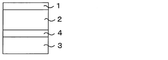
- FIG. 1 is a schematic view showing the structure of the protective film of the present invention.
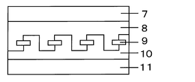
- FIG. 2 is a schematic diagram illustrating an example of the configuration of the solar cell element.
- FIG. 1 is a schematic view of the protective film of the present invention, wherein 1 is a coating layer, 2 is a resin film, 3 is a water vapor gas barrier film, and 4 is an adhesive layer.
- the resin film 2 and the water vapor gas barrier film 3 are bonded together by the adhesive layer 4, but a structure in which the water vapor gas barrier film layer is provided directly on the surface of the resin film 2 may be used.
- the coating layer is preferably provided on the surface of the resin film, but other constituent layers may be included between the coating layer and the resin film. Furthermore, you may have another structural layer in the other position in the range which does not deviate from the meaning of this invention.
- the coating layer of this invention is characterized by including an organic type ultraviolet absorber.
- the coating layer usually contains a binder in addition to the organic ultraviolet absorber.
- the organic ultraviolet absorber is preferably blended in such a blending ratio that the minimum absorption wavelength of the ultraviolet absorber between wavelengths of 300 to 400 nm is 10 ⁇ m of dry film thickness and the absorbance is 0.1 to 7, and the absorbance is 0. More preferably, the blending ratio is 2 to 5.
- the organic ultraviolet absorber is usually preferably contained in the range of 0.1 to 50% by weight of the binder, and more preferably in the range of 0.5 to 30% by weight.
- the coating layer in the present invention may contain components other than the organic ultraviolet absorber and the binder, but the coating layer in the present invention comprises 90% by weight or more of the components composed of the organic ultraviolet absorber and the binder. It is preferable that 95% by weight or more is composed of an organic ultraviolet absorber and a binder.
- the thickness of the coating layer is not particularly defined, but is, for example, 0.1 to 30 ⁇ m, preferably 0.2 to 20 ⁇ m, and more preferably 0.5 to 10 ⁇ m.
- the coating layer may be a single layer or may have a laminated structure of two or more layers, for example, 2 to 10 layers, if necessary.
- Organic ultraviolet absorber The organic ultraviolet absorber used in the present invention is not particularly defined, but is preferably an aromatic ultraviolet absorber, more preferably an ultraviolet absorber having a triazine ring structure,
- the ultraviolet absorber represented by the general formula (1) and / or the ultraviolet absorber represented by the general formula (2) are more preferable.
- the ultraviolet absorber represented by the general formula (1) and / or the ultraviolet absorber represented by the general formula (2) there is little deterioration of the water vapor gas barrier performance after the ultraviolet irradiation, and wet heat resistance is improved. Tend to.
- UV absorber represented by general formula (1)
- General formula (1) [R 1a , R 1b , R 1c , R 1d , R 1e each independently represent a monovalent substituent other than a hydrogen atom or OH, and at least one of the substituents has a Hammett's ⁇ p value Represents a substituent which is positive. Moreover, you may combine with substituents and may form a ring.
- R 1f , R 1g , R 1h , R 1i and R 1j each independently represent a monovalent substituent other than a hydrogen atom or OH. Moreover, you may combine with substituents and may form a ring.
- R 1k , R 1m , R 1n and R 1p each independently represent a hydrogen atom or a monovalent substituent. Moreover, you may combine with substituents and may form a ring. ]
- R 1a , R 1b , R 1c , R 1d and R 1e each independently represent a monovalent substituent other than a hydrogen atom or OH, and at least one of the substituents has a Hammett's ⁇ p value Represents a substituent that is positive.
- 1 to 3 preferably represent substituents having a positive Hammett's ⁇ p value, and 1 to 2 represent Hammett's rules. More preferably, it represents a substituent having a positive ⁇ p value.
- R 1a , R 1c and R 1e represents a substituent having a positive Hammett's ⁇ p value
- R 1c represents a substituent having a positive Hammett's ⁇ p value.
- R 1a , R 1b , R 1d , and R 1e represent a hydrogen atom.
- LUMO is stabilized by the electron withdrawing group, which is preferable because the excitation lifetime is shortened and the light resistance is improved.
- Examples of the monovalent substituent (hereinafter referred to as A) in the general formula (1) include, for example, a halogen atom (for example, a fluorine atom, a chlorine atom, a bromine atom, and an iodine atom), an alkyl group having 1 to 20 carbon atoms (for example, Methyl, ethyl), aryl groups having 6 to 20 carbon atoms (for example, phenyl, naphthyl), cyano groups, carboxyl groups, alkoxycarbonyl groups (for example, methoxycarbonyl), aryloxycarbonyl groups (for example, phenoxycarbonyl), substituted or unsubstituted Carbamoyl groups (eg carbamoyl, N-phenylcarbamoyl, N, N-dimethylcarbamoyl), alkylcarbonyl groups (eg acetyl), arylcarbonyl groups (eg benzoyl),
- the substituent may be further substituted, and when there are a plurality of substituents, they may be the same or different.
- the above-mentioned monovalent substituent A can be mentioned as an example of a substituent.
- Rings formed by bonding between substituents include benzene ring, pyridine ring, pyrazine ring, pyrimidine ring, triazine ring, pyridazine ring, pyrrole ring, pyrazole ring, imidazole ring, triazole ring, oxazole ring, oxadiazole And a ring, a thiazole ring, a thiadiazole ring, a furan ring, a thiophene ring, a selenophene ring, a silole ring, a gelmol ring, and a phosphole ring.
- Examples of the monovalent substituent in the general formula (1) include a halogen atom, a substituted or unsubstituted alkyl group having 1 to 20 carbon atoms, a cyano group, a carboxyl group, a substituted or unsubstituted alkoxycarbonyl group, a substituted or unsubstituted group.
- a substituted or unsubstituted sulfamoyl group, a thiocyanate group, or a substituted or unsubstituted alkylsulfonyl group is preferred, and OR U (R u represents a hydrogen atom or a monovalent substituent), an alkyl group, or an amide group. more preferably, OR u, an alkyl group more preferred.
- R u represents a hydrogen atom or a monovalent substituent, and examples of the monovalent substituent include the substituent A. Among them, it is preferable to represent a linear or branched alkyl group having 1 to 20 carbon atoms. A straight chain or branched chain alkyl group having 1 to 6 carbon atoms is more preferable.
- Examples of the straight chain or branched chain alkyl group having 1 to 6 carbon atoms include methyl, ethyl, n-propyl, i-propyl, n-butyl, i -Butyl, s-butyl, t-butyl, n-pentyl, i-pentyl, t-pentyl, n-hexyl, i-hexyl, t-hexyl, n-octyl, t-octyl, i-octyl Methyl or ethyl is preferred, and methyl is particularly preferred.
- R 1n preferably represents a monovalent substituent, and more preferably R 1n represents OR u . More preferably, R 1n represents OR U , and R 1k , R 1m , and R 1p all represent a hydrogen atom. This is because the molar extinction coefficient increases and the shielding effect increases.
- ⁇ p value is a positive Hammett equation in formula (1), preferably, sigma electron withdrawing group p value of 0.1 to 1.2.
- the electron withdrawing group having a ⁇ p value of 0.1 or more include COOR r (R r represents a hydrogen atom or a monovalent substituent), CONR s 2 (R s represents a hydrogen atom).
- CN a halogen atom, NO 2 , SO 2 R t (R t represents a hydrogen atom or a monovalent substituent), SO 3 M (M represents a hydrogen atom).
- CF 3 which is substituted by at least two halogen atoms, at least two or more alkoxy groups substituted with a halogen atom, substituted with at least two or more halogen atoms
- Hammett ⁇ p values see Hansch, C .; Leo, A .; Taft, R .; W. Chem. Rev. 1991, 91, 165-195.
- the substituent having a positive Hammett's ⁇ p value in the general formula (1) is more preferably COOR r , CONR s 2 , CN, CF 3 , halogen atom, NO 2 , SO 2 R t , SO 3 M
- R r and R s each independently represents a hydrogen atom or a monovalent substituent.
- M represents a hydrogen atom or an alkali metal].
- COOR r or CN is more preferable, and COOR r is more preferable. This is because it has excellent light resistance and solubility.
- R r represents a hydrogen atom or a monovalent substituent, and examples of the monovalent substituent include the substituent A.
- a linear or branched alkyl group having 1 to 20 carbon atoms is preferable, and a linear or branched alkyl group having 1 to 6 carbon atoms is more preferable.
- Examples of the straight or branched alkyl group having 1 to 6 carbon atoms include methyl, ethyl, n-propyl, i-propyl, n-butyl, i-butyl, s-butyl, t-butyl, n-pentyl, i- Mention may be made of pentyl, t-pentyl, n-hexyl, i-hexyl, t-hexyl, t-octyl, i-octyl and n-octyl, preferably methyl or ethyl, particularly preferably methyl.
- R 1c is any one of COOR r , CONR s 2 , CN, CF 3 , a halogen atom, NO 2 , SO 2 R t , and SO 3 M. Is preferably COOR r or CN. From the viewpoint of light resistance, R 1c is preferably CN.
- At least one of R 1f , R 1g , R 1h , R 1i , R 1j , R 1k , R 1m , R 1n , R 1p is a substituent having a positive Hammett's ⁇ p value. It is more preferable that at least one of R 1f , R 1g , R 1h , R 1i and R 1j represents a substituent having a positive ⁇ p value according to the Hammett rule, and R 1h is More preferably, it represents a substituent having a positive Hammett's ⁇ p value. It is particularly preferred that R 1c and R 1h both represent a substituent having a positive Hammett's ⁇ p value. This is because it has excellent light resistance.
- the UV absorber represented by the general formula (1) preferably has a pKa in the range of ⁇ 5.0 to ⁇ 7.0. Further, it is more preferably in the range of -5.2 to -6.5, particularly preferably in the range of -5.4 to -6.0.
- the ultraviolet absorber represented by the general formula (1) can take a tautomer depending on the structure and the environment in which it is placed. Although the present invention is described in one of the representative forms, tautomers different from those described in the present invention are also included in the compounds of the present invention.
- the ultraviolet absorber represented by the general formula (1) may contain isotopes (for example, 2 H, 3 H, 13 C, 15 N, 17 O, 18 O, etc.).
- the ultraviolet absorber represented by the general formula (1) can be synthesized by any method.
- known patent documents and non-patent documents for example, JP-A-7-188190, JP-A-11-315072, JP-A-2001-220385, “Dye and Drug”, Vol. 40, No. 12 (1995)can be synthesized with reference to pages 325-339.
- exemplary compound (19) can be synthesized by reacting 4-methoxysalicylamide, 3,5-bis (trifluoromethyl) benzoyl chloride and benzamidine hydrochloride.
- the ultraviolet absorber used by this invention consists of an ultraviolet absorber represented by General formula (1). Since the compound represented by the general formula (I) of the present invention has a substituent having a positive Hammett's ⁇ p value at a specific position, the LUMO is stabilized by the electron-attracting group, so that the excitation lifetime is It is shortened and has the characteristic of having excellent light resistance. Even when it is used as an ultraviolet absorber, when a known triazine compound is used, it has an adverse effect such as decomposition and yellowing when used for a long time. On the other hand, since the compound represented by the general formula (I) of the present invention has excellent light resistance, it does not decompose and yellow even when used for a long time.
- the compound represented by the general formula (I) may be used alone or in combination of two or more.
- Any type of UV absorber may be used in the present invention.
- a liquid dispersion, a solution, a resin composition, etc. are mentioned.
- the maximum absorption wavelength of the ultraviolet absorbent used in the present invention is not particularly limited, but is preferably 250 to 400 nm, and more preferably 280 to 380 nm.
- the full width at half maximum is preferably 20 to 100 nm, more preferably 40 to 80 nm.
- a person skilled in the art can easily measure the maximum absorption wavelength and the full width at half maximum defined in the present invention.
- the measurement method is described in, for example, “The Fourth Edition Experimental Chemistry Course 7 Spectroscopy II” (Maruzen, 1992), pages 180 to 186, edited by the Chemical Society of Japan.
- the sample is dissolved in a suitable solvent, and measurement is performed by a spectrophotometer using a cell made of quartz or glass and using two cells for sample and control.
- the solvent to be used is required to have no absorption in the measurement wavelength region, have a small interaction with the solute molecule, and have a very low volatility in addition to the solubility of the sample. Any solvent that satisfies the above conditions can be selected.
- measurement is performed using ethyl acetate (EtOAc) as a solvent.
- the maximum absorption wavelength and half width of the compound in the present invention are values measured using a quartz cell having an optical path length of 10 mm by preparing a solution having a concentration of about 5 ⁇ 10 ⁇ 5 mol ⁇ dm ⁇ 3 using ethyl acetate as a solvent. Is used.
- the half width of the spectrum is described in, for example, “Chapter 4 of Experimental Chemistry Lecture 3, Basic Operation III” (Maruzen, 1991), page 154, edited by the Chemical Society of Japan.
- the half-value width is explained with an example in which the horizontal axis is taken on the wave number scale, but the half-value width in the present invention is the value when the axis is taken on the wavelength scale,
- the unit is nm. Specifically, it represents the width of the absorption band that is half the absorbance at the maximum absorption wavelength, and is used as a value that represents the shape of the absorption spectrum.
- a spectrum with a small half-value width is a sharp spectrum
- a spectrum with a large half-value width is a broad spectrum.
- the UV-absorbing compound that gives a broad spectrum has absorption in a wide region from the maximum absorption wavelength to the long wave side. Therefore, in order to effectively block the long wave UV region without yellowing, a spectrum with a small half-value width is used.
- the ultraviolet absorbing compound having is preferable.
- the light absorption intensity that is, the oscillator strength
- the oscillator strength is proportional to the integral of the molar extinction coefficient, and the absorption spectrum.
- the oscillator strength is proportional to the product of the absorbance at the maximum absorption wavelength and the full width at half maximum (however, the full width at half maximum is a value obtained by taking an axis on the wavelength scale). This means that when the transition moment values are the same, a compound having a spectrum with a small half width has a large absorbance at the maximum absorption wavelength.
- Such UV-absorbing compounds have the advantage of being able to effectively shield the area around the maximum absorption wavelength with a small amount of use, but since the absorbance decreases sharply when the wavelength is slightly away from the maximum absorption wavelength, a wide range of areas can be used. It cannot be shielded.
- the ultraviolet absorber preferably has a molar extinction coefficient at the maximum absorption wavelength of 20000 or more, more preferably 30000 or more, and particularly preferably 50000 or more. If it is 20000 or more, since the absorption efficiency per mass of the ultraviolet absorber is sufficiently obtained, the amount of the ultraviolet absorber used for completely absorbing the ultraviolet region can be reduced. This is preferable from the viewpoint of preventing skin irritation and accumulation in a living body and from the point that bleeding out hardly occurs.
- the molar extinction coefficient the definition described in, for example, “New Edition Experimental Chemistry Course 9 Analytical Chemistry [II]” (Maruzen, 1977), page 244, etc., edited by the Chemical Society of Japan is used. The maximum absorption wavelength and the half width can be determined together.
- the ultraviolet absorbent used in the present invention can also be used in the form of a dispersion in which the ultraviolet absorbent is dispersed in a dispersion medium.
- Any medium may be used for dispersing the ultraviolet absorbent used in the present invention.
- water, an organic solvent, a resin, a resin solution, and the like can be given. These may be used alone or in combination.
- UV absorber represented by general formula (2)
- R 1a , R 1c and R 1e represent a hydrogen atom.
- R 1b and R 1d each independently represent a hydrogen atom or a substituent having a positive Hammett's ⁇ p value, and at least one represents a substituent having a positive Hammett's ⁇ p value.
- R 1g , R 1h , R 1i , R 1j , R 1k , R 1m , R 1n and R 1p each independently represent a hydrogen atom or a monovalent substituent. Moreover, you may combine with substituents and may form a ring. ]
- R 1a , R 1c and R 1e represent a hydrogen atom
- R 1b and R 1d are independently of each other a hydrogen atom or a Hammett's ⁇ p value.
- at least one of R 1b and R 1d represents a substituent having a positive Hammett's ⁇ p value, so that LUMO is stabilized by the electron withdrawing group. Life is shortened.
- the symmetry of the compound structure is broken, and it has excellent light resistance and high solubility in a solvent.
- Examples of the monovalent substituent (hereinafter referred to as A) in the general formula (2) include, for example, a halogen atom (for example, a fluorine atom, a chlorine atom, a bromine atom, and an iodine atom), an alkyl group having 1 to 20 carbon atoms (for example, Methyl, ethyl), aryl groups having 6 to 20 carbon atoms (for example, phenyl, naphthyl), cyano groups, carboxyl groups, alkoxycarbonyl groups (for example, methoxycarbonyl), aryloxycarbonyl groups (for example, phenoxycarbonyl), substituted or unsubstituted Carbamoyl groups (eg carbamoyl, N-phenylcarbamoyl, N, N-dimethylcarbamoyl), alkylcarbonyl groups (eg acetyl), arylcarbonyl groups (eg benzoyl),
- substituent may be further substituted, and when there are a plurality of substituents, they may be the same or different.
- the above-mentioned monovalent substituent A can be mentioned as an example of a substituent.
- Rings formed by bonding between substituents include benzene ring, pyridine ring, pyrazine ring, pyrimidine ring, triazine ring, pyridazine ring, pyrrole ring, pyrazole ring, imidazole ring, triazole ring, oxazole ring, oxadiazole And a ring, a thiazole ring, a thiadiazole ring, a furan ring, a thiophene ring, a selenophene ring, a silole ring, a gelmol ring, and a phosphole ring.
- Examples of the monovalent substituent in the general formula (2) include a halogen atom, a substituted or unsubstituted alkyl group having 1 to 20 carbon atoms, a cyano group, a carboxyl group, a substituted or unsubstituted alkoxycarbonyl group, a substituted or unsubstituted group.
- R 1b and R 1d each independently represent a hydrogen atom or a substituent having a positive Hammett's ⁇ p value, and at least one represents a substituent having a positive Hammett's ⁇ p value.
- Solvent solubility means solubility in an organic solvent such as ethyl acetate, methyl ethyl ketone, and toluene. It is preferably 10% by mass or more and 30% by mass in an organic solvent such as ethyl acetate, methyl ethyl ketone, and toluene. It is more preferable to dissolve the above.
- ⁇ p value is a positive Hammett equation in formula (2), preferably an electron-withdrawing group of sigma p value of 0.1-1.2, more preferably, 0.3 It is an electron withdrawing group of ⁇ 1.2.
- Specific examples of the electron withdrawing group having a ⁇ p value of 0.1 or more include COOR r (R r represents a hydrogen atom or a monovalent substituent, and includes a hydrogen atom and an alkyl group, preferably an alkyl group.
- R s represents a hydrogen atom or a monovalent substituent, such as a hydrogen atom, an alkyl group having 1 to 20 carbon atoms, an aryl group having 6 to 20 carbon atoms, 6-20 heterocyclic groups, preferably a hydrogen atom.
- acyl group formyl Group, acyloxy group, acylthio group, alkyloxycarbonyl group, aryloxycarbonyl group, dialkylphosphono group, diarylphosphono group, dialkylphosphinyl group, diarylphosphinyl group, phosphoryl group, al Killsulfinyl group, arylsulfinyl group, alkylsulfonyl group, arylsulfonyl group, acylthio group, sulfamoyl group, thiocyanate group,
- the substituent having a positive Hammett's ⁇ p value in the general formula (2) is more preferably COOR r , CONR s 2 , a cyano group, CF 3 , a halogen atom, a nitro group, or SO 3 M
- R r and R s each independently represent a hydrogen atom or a monovalent substituent.
- M represents a hydrogen atom or an alkali metal].
- Examples of the monovalent substituent include the substituent A.
- a substituent ⁇ p value is a positive Hammett equation in formula (2), more preferably a COOR r or a cyano group, more preferably a COOR r.
- R r preferably represents a hydrogen atom or an alkyl group, more preferably a linear or branched alkyl group having 1 to 20 carbon atoms, and still more preferably a linear or branched alkyl group having 1 to 15 carbon atoms.
- R r is more preferably a branched alkyl group having 5 to 15 carbon atoms from the viewpoint of solubility in a solvent.
- the branched alkyl group has a secondary carbon atom or a tertiary carbon atom, preferably contains 1 to 5 secondary carbon atoms or tertiary carbon atoms, preferably contains 1 to 3, preferably 1 or 2 It is preferable to contain it, and it is more preferable to contain 1 or 2 secondary carbon atoms and tertiary carbon atoms. Further, it preferably contains 1 to 3 asymmetric carbons.
- R r is a branched alkyl group having 5 to 15 carbon atoms containing 1 or 2 secondary carbon atoms and tertiary carbon atoms and 1 or 2 asymmetric carbons from the viewpoint of solubility in a solvent. It is particularly preferred. This is because the symmetry of the compound structure is broken and the solubility is improved.
- a linear or branched alkyl group having 1 to 6 carbon atoms is more preferable from the viewpoint of ultraviolet absorbing ability.
- Examples of the straight or branched alkyl group having 1 to 6 carbon atoms include methyl, ethyl, n-propyl, i-propyl, n-butyl, i-butyl, s-butyl, t-butyl, n-pentyl, i- Mention may be made of pentyl, t-pentyl, n-hexyl, i-hexyl, t-hexyl, n-octyl, t-octyl and i-octyl, preferably methyl or ethyl, particularly preferably methyl.
- R 1g , R 1h , R 1i , R 1j , R 1k , R 1m , R 1n and R 1p represent a monovalent substituent
- R 1h is a substituent in which the ⁇ p value in the Hammett rule is positive.
- R 1b or R 1d and R 1h represent a substituent having a positive (preferably 0.1 to 1.2) ⁇ p value according to the Hammett rule. This is because it has excellent light resistance.
- R 1h or R 1n is preferably each independently a hydrogen atom, COOR r , CONR s 2 , a cyano group, CF 3 , a halogen atom, a nitro group, or SO 3 M, and R 1h or R 1n is more preferably a hydrogen atom, R 1h and R 1n are more preferably hydrogen atoms, R 1g , R 1h , R 1i , R 1j , R 1k , R 1m , R 1n and R 1p Particularly preferably represents a hydrogen atom. It is for showing the outstanding light resistance.
- R 1b or R 1d is a substituent having a positive Hammett's ⁇ p value (preferably 0.1 to 1.2), and R 1g , R 1h , R 1i , R 1j , R 1k , R 1m , R 1n and R 1p preferably represent a hydrogen atom, and R 1b or R 1d is COOR r , CONR s 2 , a cyano group, CF 3 , More preferably, it is any one of a halogen atom, a nitro group, and SO 3 M, and R 1g , R 1h , R 1i , R 1j , R 1k , R 1m , R 1n and R 1p are hydrogen atoms. It is for showing the outstanding light resistance.
- the UV absorber represented by the general formula (2) preferably has a pKa in the range of ⁇ 5.0 to ⁇ 7.0. Further, it is more preferably in the range of -5.2 to -6.5, particularly preferably in the range of -5.4 to -6.0.
- the ultraviolet absorber represented by the general formula (2) can take a tautomer depending on the structure and the environment in which it is placed. Although the present invention is described in one of the representative forms, tautomers different from those described in the present invention are also included in the compounds of the present invention.
- the ultraviolet absorber represented by the general formula (2) may contain isotopes (for example, 2 H, 3 H, 13 C, 15 N, 17 O, 18 O, etc.).
- the ultraviolet absorber represented by the general formula (2) can be synthesized by any method.
- known patent documents and non-patent documents for example, Japanese Patent Laid-Open No. 7-188190, Japanese Patent Laid-Open No. 11-315072, Japanese Patent Laid-Open No. 2001-220385, “Dye and Drug”, Vol. 40 No. 12 (1995), 325
- exemplary compound (16) can be synthesized by reacting salicylamide, 3,5-bis (trifluoromethyl) benzoyl chloride and 2-hydroxybenzamidine hydrochloride. It can also be synthesized by reacting salicylamide, salicylic acid and 3,5-bis (trifluoromethyl) benzamidine hydrochloride.
- description of the ultraviolet absorber represented by General formula (1) can be considered.
- Binder The binder contained in the coating layer in the present invention is not particularly defined, but is preferably a siloxane-based binder, and more preferably a binder containing a compound represented by the formula (1). .
- Formula (1) R 1 m Si (OR 2 ) n O (4-mn / 2) (In the formula, R 1 is a group selected from a methyl group, an ethyl group, and a phenyl group, and R 1 may contain two or more groups, and R 2 is an alkyl having 1 to 8 carbon atoms. And R 2 may contain two or more kinds of alkyl groups, 0.2 ⁇ m ⁇ 2, n is 0.01 ⁇ n ⁇ 3, and m + n ⁇ 4.
- R 1 is a group selected from a methyl group, an ethyl group, and a phenyl group, and is preferably a methyl group and / or an ethyl group.
- R 2 is preferably a methyl group and / or an ethyl group.
- Each of R 1 and R 2 may be only one type or two or more types. Furthermore, 0.2 ⁇ m ⁇ 1 is preferable, and 0.1 ⁇ n ⁇ 2 is preferable.
- the average composition refers to a composition specified according to an NMR (nuclear magnetic resonance spectrum) measurement result and a GPC (gel permeation chromatography) measurement result using polystyrene as a standard substance.
- the binder used in the present invention preferably has a weight average molecular weight (Mw) of 1,000 to 10,000.
- the adhesive force to the resin film can be 10 N / cm or more.
- a curing catalyst may be added.
- a curing catalyst include alkyl titanates, tin octylate and dibutyltin dilaurate, and dioctyltin dimaleate.
- Metal salts of carboxylic acids include amine salts such as dibutylamine-2-hexoate, dimethylamine acetate, ethanolamine acetate; quaternary ammonium salts such as tetramethylammonium acetate; amines such as tetraethylpentamine; N— amine-based silane coupling agents such as ⁇ -aminoethyl- ⁇ -aminopropyltrimethoxysilane and N- ⁇ -aminoethyl- ⁇ -aminopropylmethyldimethoxysilane; acids such as p-toluenesulfonic acid, phthalic acid and hydrochloric acid; Aluminum alkoxide, aluminum clay Aluminum compounds such as potassium hydroxide, alkali catalysts such as potassium hydroxide, titanium compounds such as tetraisopropyl titanate, tetrabutyl titanate, titanium tetraacetylacetonate, halogenated silanes such
- the addition amount of the curing catalyst is preferably 0.001 to 20 parts by weight with respect to 100 parts by weight of the binder component. More preferably, it is 0.005 to 10 parts by weight.
- the addition amount of the curing catalyst is less than 0.001 part by weight, the curing may not be performed at room temperature, and when the addition amount of the curing catalyst exceeds 20 parts by weight, the heat resistance and weather resistance of the coating film may be deteriorated.
- Resin film The resin film used in the present invention is not particularly defined, but is preferably a transparent resin film.
- a transparent resin film When a transparent resin film is used, the haze of the protective film can be lowered, and therefore it can be preferably used as a front sheet for a solar cell.
- transparent means, for example, a total light transmittance of 80% or more.
- the resin film used in the present invention include polyolefin resins such as polyethylene, polypropylene, poly-4-methylpentene-1, and polybutene-1, polyester resins such as polyethylene terephthalate and polyethylene naphthalate, polycarbonate resins, Cellulose-based resins such as polyvinyl chloride resin, polyphenylene sulfide-based resin, polyether sulfone-based resin, polyethylene sulfide-based resin, polyphenylene ether-based resin, styrene-based resin, acrylic resin, polyamide-based resin, polyimide-based resin, and cellulose acetate Resin, fluororesin film or laminated film thereof, such as polyethylene terephthalate film, polyethylene naphthalate film, polycarbonate film, fluororesin film.
- polyolefin resins such as polyethylene, polypropylene, poly-4-methylpentene-1, and polybutene-1
- polyester resins such as polyethylene tere
- Lum and acrylic resin film is preferable.
- a polyester film having a carboxyl group content of 30 equivalents / ton or less is particularly preferable.
- the resin film may be colored or vapor-deposited as desired, and may contain an ultraviolet absorber, but the object of the present invention can be achieved even if it does not substantially contain it.
- one or both sides can be subjected to a surface treatment by an oxidation method or an unevenness method, if desired.
- the oxidation method examples include corona discharge treatment, chromic acid treatment (wet), flame treatment, hot air treatment, ozone / ultraviolet irradiation treatment and the like, and examples of the unevenness method include sand blast method and solvent treatment method. Is mentioned.
- These surface treatment methods are appropriately selected according to the type of the resin film, but in general, the corona discharge treatment method is preferably used from the viewpoints of effects and operability.
- the thickness of the resin film in the present invention is preferably 5 ⁇ m to 1000 ⁇ m, and more preferably 10 ⁇ m to 500 ⁇ m. That is, the film in the present invention includes both a film having a thickness of less than 250 ⁇ m and a sheet having a thickness of 250 ⁇ m or more. By setting it as such thickness, the improvement of dimensional stability and the nick of a film become difficult to occur, and it becomes possible to supply a protective sheet for a solar cell having a stable barrier ability.
- Water vapor gas barrier film used in the protective sheet of the present invention is not particularly defined as long as it is a film having water vapor gas barrier properties, and may be a laminate of two or more layers.
- a preferred example of the water vapor gas barrier film of the present invention is a laminate in which at least one organic layer and at least one inorganic layer are alternately laminated, preferably at least two organic layers and at least two inorganic layers. In this structure, layers are alternately stacked. By setting it as such a structure, it becomes possible to ensure high water vapor
- the organic layer in the present invention specifically includes polyester, acrylic resin, methacrylic resin, methacrylic acid-maleic acid copolymer, polystyrene, transparent fluororesin, polyimide, fluorinated polyimide, polyamide, polyamideimide, polyetherimide, Thermoplastic resins such as cellulose acylate, polyurethane, polyether ether ketone, polycarbonate, alicyclic polyolefin, polyarylate, polyether sulfone, polysulfone, fluorene ring modified polycarbonate, alicyclic ring modified polycarbonate, fluorene ring modified polyester, acryloyl compound, etc.
- the organic layer may consist of a single material or a mixture. Two or more organic layers may be laminated. In this case, each layer may have the same composition or a different composition. Further, as disclosed in US Patent Publication No. 2004-46497, a layer in which the interface with the inorganic layer is not clear and the composition continuously changes in the film thickness direction may be used.
- the organic layer is preferably a (meth) acrylate polymer.
- the (meth) acrylate polymer means a polymer obtained by polymerizing a polymerizable composition containing a (meth) acrylate monomer as a main component.
- the polymerizable composition mainly composed of a (meth) acrylate monomer preferably used in the present invention may be one kind or a mixture of several kinds of (meth) acrylate monomers.
- the molecular weight of the (meth) acrylate monomer is preferably 200 to 2000, and more preferably 400 to 1000.
- the polymerizable composition used in the present invention may contain an acidic monomer. By including an acidic monomer, interlayer adhesion is improved.
- the acidic monomer means a monomer containing an acidic group such as carboxylic acid, sulfonic acid, phosphoric acid, phosphonic acid.
- the acidic monomer used in the present invention is preferably a monomer containing a carboxylic acid group or a phosphoric acid group, more preferably a (meth) acrylate containing a carboxylic acid group or a phosphoric acid group, and a (meth) acrylate having a phosphate ester group. Is more preferable.
- a monomer other than (meth) acrylate for example, styrene derivative, maleic anhydride derivative, Epoxy compounds, oxetane derivatives, etc.
- various polymers eg polyester, methacrylic acid-maleic acid copolymer, polystyrene, transparent fluororesin, polyimide, fluorinated polyimide, polyamide, polyamideimide, polyetherimide, cellulose acylate
- the polymerizable composition containing a (meth) acrylate monomer as a main component in the present invention may contain a polymerization initiator.
- a photopolymerization initiator When a photopolymerization initiator is used, its content is preferably 0.1 mol% or more, more preferably 0.5 to 2 mol% of the total amount of the polymerizable compounds.
- the photopolymerization initiator for example, those described in paragraph No. 0028 of JP 2010-234791 A can be employed.
- the thickness of the organic layer in the present invention is not particularly defined, but is usually 100 to 5000 nm, more preferably 200 to 2000 nm per layer. Moreover, when it has two or more organic layers, each organic layer may be the same layer, or a different layer.
- the method for forming the organic layer is not particularly defined, but for example, the description of paragraph numbers 0029 and 0030 of JP 2010-234791 A can be employed.
- the inorganic layer is not particularly limited as long as it is composed of an inorganic material and has a gas barrier property.
- the inorganic substance includes boron, magnesium, aluminum, silicon, titanium, zinc, tin oxide, nitride, oxynitride, carbide, hydride, and the like. These may be pure substances, or may be a mixture of multiple compositions or a gradient material layer. Among these, it is preferable to include at least one of silicon and aluminum and at least one of oxygen and nitrogen.
- any method for forming the inorganic layer any method can be used as long as the target thin film can be formed.
- a sol-gel method, a sputtering method, a vacuum evaporation method, an ion plating method, a plasma CVD method, and the like are suitable.
- the formation method described in JP-A-361774 can be employed.
- CVD using inductively coupled plasma CVD or microwaves set to electron cyclotron resonance conditions and plasma applied with a magnetic field
- CVD using inductively coupled plasma CVD or microwaves set to electron cyclotron resonance conditions and plasma applied with a magnetic field
- PVD using microwaves set to electron cyclotron resonance conditions and plasma applied with a magnetic field
- a gas source such as silane or a liquid source such as hexamethyldisilazane can be used as a silicon supply source.
- the smoothness of the inorganic layer formed according to the present invention is preferably less than 1 nm, more preferably 0.5 nm or less, as an average roughness (Ra value) of 1 ⁇ m square. For this reason, it is preferable that the inorganic layer be formed in a clean room.
- the degree of cleanness is preferably class 10000 or less, more preferably class 1000 or less.
- the thickness of the inorganic layer is not particularly limited, but is usually in the range of 5 to 500 nm, preferably 10 to 200 nm, per layer.
- the inorganic layer may have a laminated structure including a plurality of sublayers. In this case, each sublayer may have the same composition or a different composition. Further, as described above, as disclosed in US 2004-46497, the interface with the organic layer is not clear, and the layer may be a layer whose composition changes continuously in the film thickness direction.
- the organic layer and the inorganic layer can be laminated by sequentially forming the organic layer and the inorganic layer in accordance with a desired layer structure.
- the organic layer is also preferably formed by a vacuum film forming method such as the flash vapor deposition method. .
- a vacuum film forming method such as a sputtering method, a vacuum vapor deposition method, an ion plating method, or a plasma CVD method
- the organic layer is also preferably formed by a vacuum film forming method such as the flash vapor deposition method.
- the pressure is more preferably 100 Pa or less, more preferably 50 Pa or less, and further preferably 20 Pa or less.
- the present invention more preferably has a layer structure in which at least two organic layers and at least two inorganic layers are alternately laminated. In the alternate lamination, the layers may be laminated in the order of organic layer / inorganic layer / organic layer / inorganic layer from the support side, or in the order of inorganic layer / organic layer / inorganic layer / organic layer.
- the water vapor gas barrier film of the present invention may be obtained by laminating the above laminate on a plastic film.
- a plastic film As for the details of the plastic film, for example, the description in paragraph numbers 0039 and 0043 of JP 2010-234791 A can be adopted.
- the thickness of the plastic film is not particularly limited, but is typically 1 to 800 ⁇ m, preferably 10 to 200 ⁇ m.
- the water vapor gas barrier film used for the protective film of the present invention may be a water vapor gas barrier resin film.
- Such water vapor gas barrier resin films include polyvinyl chloride, polyvinylidene chloride, ethylene vinyl alcohol copolymer, polytetrafluoroethylene, polychlorotrifluoroethylene, polyvinylidene fluoride, polyvinyl fluoride, ethylene tetrafluoride.
- Preferred examples include an ethylene copolymer and an ethylene / chlorotrifluoroethylene copolymer.
- the thickness of the resin film in the present invention is preferably 5 ⁇ m to 1000 ⁇ m, more preferably 10 ⁇ m to 500 ⁇ m.
- Adhesive Layer The adhesive layer when the resin film and the water vapor gas barrier film are bonded together using an adhesive will be described.
- the adhesive layer in the present invention is not particularly defined as long as an adhesive is included, and 98% by weight or more of the layer is preferably an adhesive.
- an ultraviolet (UV) curable adhesive or a thermosetting adhesive can be preferably used, and an ultraviolet curable adhesive is more preferable.
- the type of the adhesive is not particularly defined, but examples of the UV curable adhesive include epoxy-based, acrylate-based, and urethane-based examples, and urethane-based adhesives are more preferable.
- thermosetting adhesive examples include epoxy-based, acrylate-based, and urethane-based examples, and urethane-based adhesives are more preferable.
- the thickness of the adhesive layer is preferably 0.1 to 20 ⁇ m, and more preferably 0.5 to 5 ⁇ m.
- an easy adhesion layer may be provided.
- the easy-adhesion layer is a kind of a layer called a primer layer, an undercoat layer, an undercoat layer, or the like, and is a layer provided for the purpose of adjusting the interface state between layers. By providing such a layer, there is an advantage of particularly improving the adhesiveness.
- the solar cell of the present invention refers to a system that converts sunlight into electricity.
- An example of the structure is shown in FIG. That is, the front sheet layer 7, the filling adhesive resin layer 8, the solar cell element main part 9, the filling adhesive resin layer 10, and the back sheet layer 11 are the basic configuration from the side where sunlight enters.
- the protective film of the present invention is preferably used for the front sheet layer.
- the arrow side in FIG. 1 is the side irradiated with sunlight. Of course, it may be used for the backsheet layer.
- Some of these solar cells are built into the roof of a house, installed in farm ponds, ranches, wastewater and sewage treatment facilities, volcanoes and hot spring areas, buildings and fences, and used in electronic parts.
- Some of the solar cell modules transmit light called daylighting type or see-through type and are used for soundproof walls such as windows, highways and railways. In the present invention, it can be a particularly flexible type.
- Japanese Patent Application Laid-Open No. 2008-31680 has an example of a back sheet using polyester
- Japanese Patent Application Laid-Open No. 2009-248377 has an example of a back sheet using polyester or fluorine-free resin.
- the publication describes examples of a back sheet using a film of a fluorine resin, a cyclic polyolefin resin, a polyester resin, a polyamide resin, a polycarbonate resin, or a poly (meth) acrylic resin. .
- a backsheet has the adhesive force of 10 N / cm or more with respect to the sealing material used when forming a solar cell module.
- a layer that increases the adhesive force on the side of the back sheet in contact with the sealing material.
- the silicone-based polymer layer includes a (poly) siloxane structural unit having a mass ratio of 15 to 85% by mass and a non-siloxane structural unit having a mass ratio of 85 to 15% by mass represented by the following general formula (1) in the molecule. Containing at least one kind of composite polymer.
- the composite polymer in the present invention is a block copolymer obtained by copolymerizing (poly) siloxane and at least one polymer.
- the (poly) siloxane and the copolymerized polymer may be one kind alone, or two or more kinds.
- R 1 and R 2 each independently represent a hydrogen atom, a halogen atom, or a monovalent organic group.
- R 1 and R 2 may be the same or different, and the plurality of R 1 and R 2 may be the same or different from each other.
- n represents an integer of 1 or more.
- R 1 and R 2 may be the same or different and each represents a hydrogen atom, a halogen atom, or a monovalent organic group.
- — (Si (R 1 ) (R 2 ) —O) n —” is a (poly) siloxane segment derived from various (poly) siloxanes having a linear, branched or cyclic structure.
- Examples of the halogen atom represented by R 1 and R 2 include a fluorine atom, a chlorine atom, and an iodine atom.
- the “monovalent organic group” represented by R 1 and R 2 is a group that can be covalently bonded to the Si atom, and may be unsubstituted or may have a substituent.
- Examples of the monovalent organic group include an alkyl group (e.g., methyl group, ethyl group), an aryl group (e.g., phenyl group), an aralkyl group (e.g., benzyl group, phenylethyl), and an alkoxy group (e.g.
- Methoxy group, ethoxy group, propoxy group, etc. Methoxy group, ethoxy group, propoxy group, etc.), aryloxy group (eg, phenoxy group etc.), mercapto group, amino group (eg: amino group, diethylamino group etc.), amide group and the like.
- R 1 and R 2 are each independently a hydrogen atom, a chlorine atom, a bromine atom, an unsubstituted or substituted, in terms of adhesion to adjacent materials such as a polymer substrate and durability in a wet and heat environment.
- Alkyl groups having 1 to 4 carbon atoms particularly methyl group, ethyl group
- unsubstituted or substituted phenyl group unsubstituted or substituted alkoxy group
- mercapto group unsubstituted amino group
- amide group More preferably an unsubstituted or substituted alkoxy group (preferably an alkoxy group having 1 to 4 carbon atoms) from the viewpoint of durability in a moist heat environment.
- the n is preferably 1 to 5000, and more preferably 1 to 1000.
- the ratio of “— (Si (R 1 ) (R 2 ) —O) n —” (the (poly) siloxane structural unit represented by the general formula (1)) in the composite polymer is the total mass of the composite polymer.
- the range of 20 to 80% by mass is preferable from the viewpoints of adhesion to a polymer substrate and durability in a moist heat environment.
- the ratio of the polysiloxane moiety is less than 15% by mass, the adhesion to the polymer substrate and the adhesion durability when exposed to a moist heat environment are poor, and when it exceeds 85% by mass, the liquid becomes unstable.
- non-siloxane structural unit copolymerized with the siloxane structural unit is not particularly limited except that it does not have a siloxane structure, and is derived from an arbitrary polymer. Any of the polymer segments may be used. Examples of the polymer (precursor polymer) that is a precursor of the polymer segment include various polymers such as a vinyl polymer, a polyester polymer, and a polyurethane polymer. From the viewpoint of easy preparation and excellent hydrolysis resistance, vinyl polymers and polyurethane polymers are preferred, and vinyl polymers are particularly preferred.
- Typical examples of the vinyl polymer include various polymers such as an acrylic polymer, a carboxylic acid vinyl ester polymer, an aromatic vinyl polymer, and a fluoroolefin polymer.
- acrylic polymers that is, acrylic structural units as non-siloxane structural units
- the polymer which comprises a non-siloxane type structural unit may be single 1 type, and 2 or more types of combined use may be sufficient as it.
- the precursor polymer forming the non-siloxane structural unit is preferably one containing at least one of an acid group and a neutralized acid group and / or a hydrolyzable silyl group.
- the vinyl polymer includes, for example, (a) a vinyl monomer containing an acid group and a vinyl monomer containing a hydrolyzable silyl group and / or a silanol group.
- Such a precursor polymer can be produced and obtained by using, for example, the method described in paragraph Nos. 0021 to 0078 of JP-A-2009-52011.
- the composite polymer may be used alone as a binder, or may be used in combination with other polymers.
- the ratio of the composite polymer in the present invention is preferably 30% by mass or more, more preferably 60% by mass or more of the total binder.
- the ratio of the composite polymer is 30% by mass or more, the adhesiveness with the polymer base material and the durability under a moist heat environment are more excellent.
- the molecular weight of the composite polymer is preferably 5,000 to 100,000, and more preferably 10,000 to 50,000.
- the temperature is about 20 to 150 ° C. for about 30 minutes to 30 hours ( (Preferably, the reaction can be performed at 50 to 130 ° C. for 1 to 20 hours).
- various silanol condensation catalysts such as an acidic compound, a basic compound, and a metal containing compound, can be added.
- water and a silanol condensation catalyst are added to a mixture of a precursor polymer and an alkoxysilane compound, and a temperature of about 20 to 150 ° C. for 30 minutes to 30 minutes. It can be prepared by performing hydrolysis condensation for about an hour (preferably at 50 to 130 ° C. for 1 to 20 hours).
- the polymer layer has a structural portion derived from a cross-linking agent that cross-links between the composite polymers. That is, the polymer layer can be formed using a crosslinking agent capable of crosslinking between the composite polymers.
- a crosslinking agent capable of crosslinking between the composite polymers.
- crosslinking agent examples include epoxy-based, isocyanate-based, melamine-based, carbodiimide-based, and oxazoline-based crosslinking agents.
- crosslinking agents such as carbodiimide compounds and oxazoline compounds are preferable.
- the solar cell in which the protective film of the present invention is preferably used is not particularly limited, but for example, a single crystal silicon solar cell, a polycrystalline silicon solar cell, a single junction type, or an amorphous structure composed of a tandem structure type, etc.
- III-V group compound semiconductor solar cells such as gallium arsenide (GaAs) and indium phosphorus (InP)
- II-VI group compound semiconductor solar cells such as cadmium tellurium (CdTe), copper / indium / selenium system ( So-called CIS-based), copper / indium / gallium / selenium-based (so-called CIGS-based), copper / indium / gallium / selenium / sulfur-based (so-called CIGS-based) I-III-VI group compound semiconductor solar cells, Examples include dye-sensitized solar cells and organic solar cells.
- the solar cell is composed of a copper / indium / selenium system (so-called CIS system), a copper / indium / gallium / selenium system (so-called CIGS system), a copper / indium / gallium / selenium / sulfur system.
- CIS system copper / indium / selenium system
- CIGS system copper / indium / gallium / selenium system
- CIGSS type I-III-VI group compound semiconductor solar cell
- reaction mixture was extracted and separated with an aqueous ammonium chloride solution and ethyl acetate, and the resulting organic phase was washed with saturated brine and separated.
- the organic phase thus obtained was concentrated by a rotary evaporator to obtain a residue obtained as a crude product of compound (X-2).
- reaction mixture was cooled to an internal temperature of 25 ° C.
- 105 g of 1,5-naphthalenedisulfonic acid was added to the mother liquor filtered through celite and separated by furnace, the internal temperature was raised to 70 ° C., and the mixture was stirred for 30 minutes. Thereafter, the mixture was gradually cooled to room temperature, and the crystals were separated by filtration to obtain 100 g of compound (X-4). The yield was 72% starting from compound (X-1). The obtained crystal was light brown.
- Exemplary compound (m-18) Exemplified compound (m-18) was synthesized in the same manner as Exemplified compound (m-19) except that the starting material 1-hexanol was changed to 1-butanol.
- 1 H NMR (CDCl 3 ): ⁇ 1.03-1.07 (3H), ⁇ 1.55-1.87 (4H), ⁇ 4.41-4.45 (2H), ⁇ 7.04-7.12 (4H ), ⁇ 7.53-7.58 (2H), ⁇ 7.68-7.73 (1H), ⁇ 8.34-8.36 (1H), ⁇ 8.54-8.56 (2H), ⁇ 8.62- 8.64 (1H), ⁇ 9.15 (1H), ⁇ 12.93 (2H) ⁇ max 354 nm (EtOAc)
- Exemplified compound (m-25) was synthesized by the same preparation method as Exemplified compound (m-19) except that the starting material 1-hexanol was changed to fine oxocol 180N.
- 1 H NMR (CDCl 3 ): ⁇ 0.72-1.86 (35H), ⁇ 4.30-4.37 (2H), ⁇ 7.04-7.10 (4H), ⁇ 7.51-7.55 (2H ), ⁇ 7.68-7.72 (1H), ⁇ 8.32-8.34 (1H), ⁇ 8.51-8.53 (2H), ⁇ 8.61-8.63 (1H), ⁇ 9.14 ( 1H), ⁇ 12.91 (2H) ⁇ max 354 nm (EtOAc)
- Exemplified compound (m-71) was synthesized in the same manner as Exemplified compound (m-3), except that the starting material salicylamide was changed to 4-methoxysalicylamide.
- Exemplified compound (m-73) was synthesized in the same manner as Exemplified compound (m-19) except that the starting material 1-hexanol was changed to 3,7-dimethyl-1-octanol.
- Example-1 to Example-32 ⁇ Production of polyethylene terephthalate film> -Synthesis of polyester-
- a slurry of 100 kg of high-purity terephthalic acid (manufactured by Mitsui Chemicals Co., Ltd.) and 45 kg of ethylene glycol (manufactured by Nippon Shokubai Co., Ltd.) was previously charged with about 123 kg of bis (hydroxyethyl) terephthalate, temperature 250 ° C., pressure 1.2
- the esterification reaction tank maintained at ⁇ 10 5 Pa was sequentially supplied over 4 hours, and the esterification reaction was further performed over 1 hour after the completion of the supply. Thereafter, 123 kg of the obtained esterification reaction product was transferred to a polycondensation reaction tank.
- the reaction system was gradually heated from 250 ° C. to 285 ° C. and the pressure was reduced to 40 Pa. The time to reach the final temperature and final pressure was both 60 minutes.
- the predetermined stirring torque (97 kg ⁇ cm) was reached, the reaction system was purged with nitrogen, returned to normal pressure, and the polycondensation reaction was stopped. The time from the start of decompression to the arrival of the predetermined stirring torque was 3 hours. Then, the obtained polymer melt was discharged into cold water in a strand form and immediately cut to produce polymer pellets (diameter: about 3 mm, length: about 7 mm).
- ⁇ Preparation of base film with UV absorber coating> As a siloxane binder, 100 parts by weight of an alkoxy silicone oligomer (Shin-Etsu Chemical Co., Ltd., X-40-9250), 5 parts by weight of a titanium-based curing catalyst (Shin-Etsu Chemical Co., Ltd., D-20), 100 parts by weight of methyl ethyl ketone Mix and adjust. Further, a coating solution was prepared by adding 20 parts by weight of the ultraviolet absorbent shown in Table 1. Next, the coating agent is applied onto the 200 ⁇ m polyethylene terephthalate film so as to have a dry film thickness of 6.3 ⁇ m, dried at room temperature for 6 hours, and each film with UV absorber coating (A ) Respectively.
- an alkoxy silicone oligomer Shin-Etsu Chemical Co., Ltd., X-40-9250
- a titanium-based curing catalyst Shin-Etsu Chemical Co., Ltd., D-20
- ⁇ Creation of water vapor barrier film> On a polyethylene terephthalate film having a thickness of 50 ⁇ m, the following polymerizable compounds (total 14 parts by weight), polymerization initiator (manufactured by Ciba Specialty Chemicals, IRGACURE 907, 1 part by weight), 2-butanone (185 parts by weight)
- the resulting composition was applied with a wire bar and cured by irradiation with an ultraviolet ray irradiation amount of 0.5 J / cm 2 in an atmosphere of 100 ppm nitrogen to prepare an organic layer.
- the film thickness of the organic layer was 500 nm.
- Al 2 O 3 was formed on the surface of the organic layer by vacuum sputtering (reactive sputtering) so as to have a film thickness of 40 nm.
- an organic polymer layer was formed on the Al 2 O 3 in the same manner as above to obtain a water vapor barrier film (B).
- Composition of polymerizable compound Compounds A to D shown below were used in the ratios shown below.
- Compound A manufactured by Kyoeisha Chemical Co., Ltd., light acrylate 1,9-ND-A: 50% by mass
- Compound B Daicel Cytec Co., Ltd.
- TMPTA 30% by mass
- Compound C manufactured by Daicel Cytec Co., Ltd.
- IRR 214K: 10% by mass
- Compound D Nippon Kayaku Co., Ltd., KAYARAD, PM-21: 10% by mass
- the uncoated surface of the film with UV absorber coating (A) and the Al 2 O 3 film side of the water vapor barrier film (B) are bonded together via a urethane adhesive (Mitsui Chemicals, Takelac A971), and a sample (C -1) to (C-32) were obtained.
- a urethane adhesive Mitsubishi Chemicals, Takelac A971
- the obtained protective film was evaluated according to the following items.
- Total light transmittance The total light transmittance was measured using a haze meter (NDH 5000, manufactured by Nippon Denshoku Industries Co., Ltd.) according to JIS K7361-1.
- UV resistance For each evaluation, 0.53 kW / m 2 (wavelength: 300 to 400 nm), black panel temperature of 63 ° C., humidity in the tank using a metallizing vertical weather meter (MV3000 manufactured by Suga Test Instruments) Evaluation was performed after an ultraviolet exposure test was performed on the test sample at 50% for 2000 hours. In addition, the b value was evaluated after being left to stand for 1000 hours in an environment of 85 ° C. and 85 RH% in a high-temperature and high-humidity tank and then dried at room temperature. The results obtained are shown in the table below.
- Comparative Example-1 Comparative Example-1 was carried out in the same manner as in Example-1 except that no ultraviolet absorber was added, and the same evaluation as in Example-1 was performed. The results are shown in the table below.
- Comparative Example-2 Comparative Example-3 Comparative Example-2 in the same manner as in Example-1 except that the following titanium dioxide (Taipeke R-780-2, manufactured by Ishihara Sangyo Co., Ltd.) was used as the UV absorber, and the addition amount was changed as shown in the table. The same evaluation as in Example 1 was performed. The results are shown in the table below.
- titanium dioxide Tipeke R-780-2, manufactured by Ishihara Sangyo Co., Ltd.
- Example-33 A water vapor barrier film was prepared in the same manner as in Example 1 using a polyethylene terephthalate film having a thickness of 200 ⁇ m instead of a thickness of 50 ⁇ m.
- a sample was obtained by forming the UV absorber coating used in Example-26 on the surface opposite to the surface on which the water vapor barrier layer was formed. This sample is a sample in which a UV absorber coating is formed on one side of a 200 ⁇ m polyethylene terephthalate film and a water vapor barrier layer is formed on the opposite side. This sample was also evaluated in the same manner as in Example-1. The results are shown in the table below.
- Example-34 Example 34 was carried out in the same manner as Example 26 except that the composition and formation conditions of the coating solution for UV absorber coating in Example 26 were changed as follows.
- -Composition of coating solution- Acrylic / silicone binder 456.5 parts by mass (Ceranate WSA-1070, manufactured by DIC Corporation, solid content: 40% by mass)
- Carbodiimide compound (crosslinking agent) 23.3 parts by mass (Carbodilite V-02-L2, manufactured by Nisshinbo Co., Ltd., solid content: 40% by mass)
- Surfactant 9.7 parts by mass (Naroacty CL95, manufactured by Sanyo Chemical Industries, Ltd., solid content: 1% by mass)
- Compound m-21 dispersion 241.5% by mass ⁇ Distilled water: 231.8 parts by mass
- Emulsion 1 When the average particle diameter of the obtained emulsion 1 was measured, the median diameter was 120 nm.
- the organic solvent was distilled off from the emulsion 1 using the evaporator, and the dispersion 1 was obtained. When the amount of the remaining solvent was measured by gas chromatography, it was 0.7% or less. When the average particle diameter of the dispersion 1 was measured, the median diameter was 121 nm. This sample was evaluated in the same manner as in Example-1. The results are shown in the table below.
- Example-35 Example 35 was performed in the same manner as Example 33 except that the same UV absorber coating as in Example 34 was used. This sample was evaluated in the same manner as in Example-1. The results are shown in the table below.
- composition of coating solution -Silicone acrylic binder: 396.5 parts by mass (Ceranate WSA1070, manufactured by DIC Corporation, solid content: 40% by mass) -Titanium dioxide dispersion: 493.9 parts by mass-Carbodiimide compound (crosslinking agent): 49.0 parts by mass (Carbodilite V-02-L2, manufactured by Nisshinbo Industries, Inc., solid content: 40% by mass) Oxazoline compound (crosslinking agent) 16.8 parts by mass (Epocross WS700, manufactured by Nippon Shokubai Co., Ltd., solid content: 25% by mass) -Surfactant: 15.0 parts by mass (Naroacty CL95, manufactured by Sanyo Chemical Industries, solid content: 1% by mass) ⁇ Distilled water: 28.8 parts by mass
- undercoat layer-forming coating solution was applied to one surface of a PET substrate so that the binder amount was 5.4 g / m 2 in terms of coating amount, and dried at 180 ° C. for 1 minute to obtain a dry thickness. Formed an undercoat layer of about 7.1 ⁇ m.
- composition of coating solution ⁇ Obligato SW0011F (binder): 345.0 parts by mass (fluorine binder, manufactured by AGC Co., Ltd., solid content: 36% by mass) Carbodiimide compound (crosslinking agent, A-1) 62.3 parts by mass (Carbodilite V-02-L2, manufactured by Nisshinbo Co., Ltd., solid content: 40% by mass) ⁇ Surfactant: 60.0 parts by mass (Naroacty CL95, manufactured by Sanyo Chemical Industries, solid content: 1% by mass) Colloidal silica: 3.9 parts by mass (Snowtex UP, manufactured by Nissan Chemical Co., Ltd., solid content: 20% by mass) Silane coupling agent: 78.5 parts by mass (TSL8340, manufactured by Momentive Performance Materials
- the obtained coating solution for forming a fluoropolymer layer was applied onto a back surface undercoat layer provided on one side of a PET substrate so that the amount of the binder was 2.0 g / m 2 , and the coating solution was 1 at 180 ° C. It was dried for 5 minutes to form a fluorine-containing polymer layer having a dry thickness of about 2 ⁇ m.
- ⁇ Surface undercoat layer> Composition of coating solution
- -Acrylic binder 25.7 parts by mass (EM48D, manufactured by Daicel Corporation, solid content: 28% by mass)
- Polyolefin binder 35.6 parts by mass (Arrow Base SE1013N, manufactured by Unitika Ltd., solid content: 20% by mass)
- Carbodiimide compound (crosslinking agent) 23.3 parts by mass (Carbodilite V-02-L2, manufactured by Nisshinbo Co., Ltd., solid content: 40% by mass)
- Surfactant 9.7 parts by mass (Naroacty CL95, manufactured by Sanyo Chemical Industries, Ltd., solid content: 1% by mass)
- Compound m-21 dispersion 241.5% by mass
- Distilled water 231.8 parts by mass -Formation of surface
- ⁇ Reflective layer / also serves as an easy adhesion layer> -Preparation of coating solution for forming reflective layer-
- ⁇ Reflective layer / also serves as an easy adhesion layer> -Preparation of coating solution for forming reflective layer-
- Each component in the following composition was mixed to prepare a coating solution for forming a reflective layer.
- Composition of coating solution ⁇ Titanium dioxide dispersion: 357.6 parts by mass (common to those used in the back surface undercoat layer) ⁇ Polyolefin binder: 514.5 parts by mass (Arrow Base SE1013N, manufactured by Unitika Ltd., solid content: 20% by mass) -Oxazoline compound (crosslinking agent) 52.8 parts by mass (Epocross WS700, manufactured by Nippon Shokubai Co., Ltd., solid content: 25% by mass) ⁇ Surfactant: 28.0 parts by mass (Naroacty CL95, manufactured by Sanyo Chemical Industries, solid content: 1% by mass) ⁇ Distilled
- the obtained coating solution for forming the reflective layer is applied on the surface undercoat layer provided on the PET substrate so that the binder amount is 3.1 g / m 2 and dried at 180 ° C. for 1 minute.
- a reflective layer having a dry thickness of about 6 ⁇ m was formed.
- Electrode and dielectric roll gap clearance 1.6 mm Processing frequency: 9.6 kHz Processing speed: 20 m / min Processing intensity: 0.375 kV ⁇ A ⁇ min / m 2
- Processing frequency 9.6 kHz Processing speed: 20 m / min Processing intensity: 0.375 kV ⁇ A ⁇ min / m 2
- seat was piled up in this order, and the back sheet
- the adhesion conditions of EVA are as follows. Using a vacuum laminator, evacuation was performed at 128 ° C. for 3 minutes, and then pressure was applied for 2 minutes to temporarily bond. Thereafter, the main adhesion treatment was performed in a dry oven at 150 ° C. for 30 minutes.
- Example-1 a crystalline solar cell module using the sample obtained in Example-1 as a front sheet was obtained.
- solar cell modules were produced using the samples of Examples-2, 3, 20, 26, 33, 34, and 35. Since this solar cell module does not use a glass plate, it is lightweight.
- the power generation operation was performed using the produced solar cell module, all the solar cell modules showed good power generation performance as a solar cell. Further, even after the solar cell module was held in an atmosphere of 120 ° C. and 100% RH for 48 hours, no peeling or discoloration of the front sheet and the back sheet was observed, and a good appearance was maintained. Furthermore, when power generation operation was performed using these solar cell modules, all the solar cell modules showed the same power generation performance as before the wet heat condition was maintained.
- the protective film of the present invention is comprehensively excellent in transmittance, water vapor barrier property, adhesion, adhesiveness and flex resistance. Therefore, it can be preferably used as a protective sheet member for a solar cell, particularly a front sheet member. Moreover, the protective film of this invention can be used as the weather-resistant protective film which can endure long-term ultraviolet exposure. Specifically, it can be a protective film that can maintain water vapor barrier properties, film strength, transmittance, etc. even after exposure to ultraviolet rays for a long period of time or after exposure to high temperature and high humidity.
- the film strength refers to film adhesion, film adhesion, surface crack resistance when bent, and the like.
- strength under high temperature and high humidity can be maintained by containing an organic type ultraviolet absorber in a surface coating layer.
Landscapes
- Compositions Of Macromolecular Compounds (AREA)
- Laminated Bodies (AREA)
- Photovoltaic Devices (AREA)
Abstract
透過率、水蒸気ガスバリア性、耐屈曲性に総合的に優れた保護フィルムを提供する。水蒸気ガスバリアフィルムと、樹脂フィルムと、有機系紫外線吸収剤を含有するコーティング層とを、該順に有する保護フィルム。
Description
本発明は、太陽電池等、耐候性を必要とする素子等を保護するための保護フィルムに関する。
太陽電池モジュール用の保護シートが検討されている。例えば、特許文献1には、基材シートの光照射面の反対側の面に、ガスバリアシートと、紫外線吸収性化合物を含有する樹脂層が積層されている太陽電池モジュール用表面保護シートが開示されている。また、特許文献2には、合成樹脂フィルムの少なくとも片面に酸化珪素系薄膜層および紫外線遮断層を設けた保護フィルムが開示されている。
ここで、本発明者が検討を行ったところ、特許文献1のように樹脂層を最表層とすると、紫外線照射後の保護シートの透過率や湿熱後の保護シートの透過率が著しく劣ることが分かった。特に、樹脂フィルム自身の耐候性が低い場合、樹脂フィルム自身が紫外線暴露によって黄変、白化、強度低下などを生じ、長期間の暴露経時に耐えられなくなることが分かった。
一方、特許文献2に記載のように、合成樹脂フィルムの少なくとも片面に酸化珪素系薄膜層および紫外線遮断層を設けた保護フィルムでは、高温高湿条件下でのガスバリア性や屈曲時のガスバリア性が劣ることが分かった。屈曲時のガスバリア性が劣ると、屈曲する面を保護する場合に、充分なガスバリア性が得られないという問題がある。
本発明は、上記問題を解決することを目的としたものであって、透過率、水蒸気ガスバリア性、耐屈曲性に総合的に優れた保護フィルムを提供することを目的とする。
一方、特許文献2に記載のように、合成樹脂フィルムの少なくとも片面に酸化珪素系薄膜層および紫外線遮断層を設けた保護フィルムでは、高温高湿条件下でのガスバリア性や屈曲時のガスバリア性が劣ることが分かった。屈曲時のガスバリア性が劣ると、屈曲する面を保護する場合に、充分なガスバリア性が得られないという問題がある。
本発明は、上記問題を解決することを目的としたものであって、透過率、水蒸気ガスバリア性、耐屈曲性に総合的に優れた保護フィルムを提供することを目的とする。
かかる状況のもと、本発明者が鋭意検討を行った結果、保護フィルムの積層順序を、水蒸気ガスバリアフィルム、樹脂フィルム、コーティング層の順にし、かつ、コーティング層に、有機系紫外線吸収剤を含有させることによって、上記課題を解決しうることを見出し、本発明を完成するに至った。具体的には、以下の手段により、上記課題は達成された。
(1)水蒸気ガスバリアフィルムと、樹脂フィルムと、有機系紫外線吸収剤を含有するコーティング層とを、該順に有する保護フィルム。
(2)コーティング層が、樹脂フィルムの表面に設けられている(1)に記載の保護フィルム。
(3)有機系紫外線吸収剤が、芳香族系紫外線吸収剤である、(1)または(2)に記載の保護フィルム。
(4)有機系紫外線吸収剤が、トリアジン環構造を有する化合物である、(1)または(2)に記載の保護フィルム。
(5)有機系紫外線吸収剤が、下記一般式(1)で表される化合物である、(1)または(2)に記載の保護フィルム。
一般式(1)
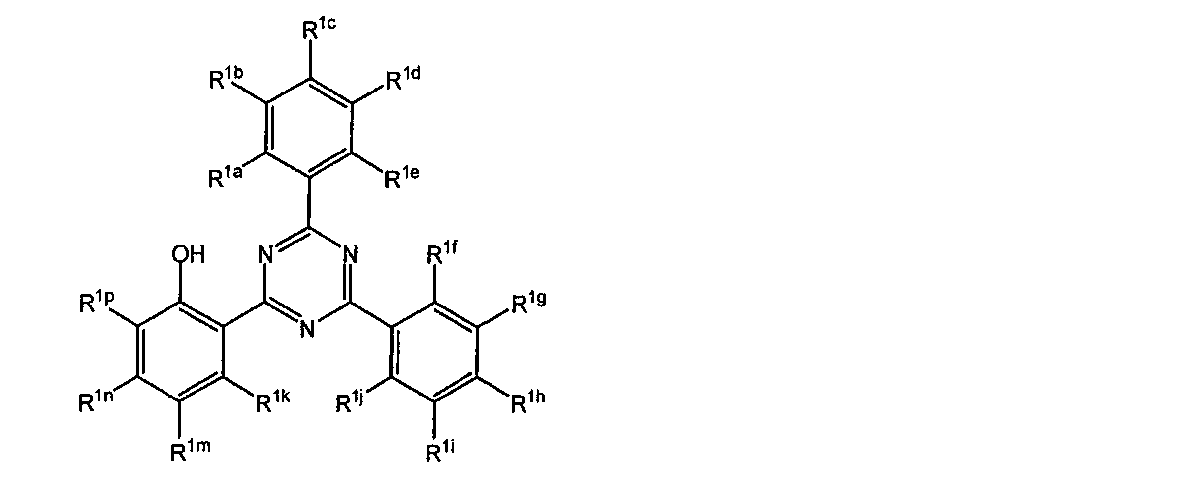
[R1a、R1b、R1c、R1d、R1eは、互いに独立して、水素原子、又はOHを除く1価の置換基を表し、置換基のうち少なくとも1つは、ハメット則のσp値が正である置換基を表す。また置換基同士で結合して環を形成しても良い。R1f、R1g、R1h、R1i、R1jは、互いに独立して、水素原子又はOHを除く1価の置換基を表す。また置換基同士で結合して環を形成しても良い。R1k、R1m、R1n、R1pは、互いに独立して、水素原子又は1価の置換基を表す。また置換基同士で結合して環を形成しても良い。]
(6)前記1価の置換基が、ハロゲン原子、置換又は無置換の炭素数1~20のアルキル基、シアノ基、カルボキシル基、置換又は無置換のアルコキシカルボニル基、置換又は無置換のカルバモイル基、置換又は無置換のアルキルカルボニル基、ニトロ基、置換又は無置換のアミノ基、ヒドロキシ基、炭素数1~20のアルコキシ基、置換又は無置換のアリールオキシ基、置換又は無置換のスルファモイル基、チオシアネート基、又は置換又は無置換のアルキルスルホニル基であり、置換基を有する場合の置換基がハロゲン原子、炭素数1~20のアルキル基、シアノ基、カルボキシル基、アルコキシカルボニル基、カルバモイル基、アルキルカルボニル基、ニトロ基、アミノ基、ヒドロキシ基、炭素数1~20のアルコキシ基、アリールオキシ基、スルファモイル基、チオシアネート基、又はアルキルスルホニル基であることを特徴とする、(5)に記載の保護フィルム。
(7)前記R1cが、ハメット則のσp値が正である置換基であることを特徴とする、(5)または(6)に記載の保護フィルム。
(8)有機系紫外線吸収剤が、下記一般式(2)で表される化合物である、(1)または(2)に記載の保護フィルム。
一般式(2)

[R1a、R1c及びR1eは、水素原子を表す。R1b及びR1dは、互いに独立して、水素原子又はハメット則のσp値が正である置換基を表し、少なくとも1つは、ハメット則のσp値が正である置換基を表す。R1g、R1h、R1i、R1j、R1k、R1m、R1n及びR1pは、互いに独立して、水素原子又は1価の置換基を表す。また置換基同士で結合して環を形成しても良い。]
(9)前記一般式(2)で表される紫外線吸収剤における1価の置換基が、ハロゲン原子、置換又は無置換の炭素数1~20のアルキル基、シアノ基、カルボキシル基、置換又は無置換のアルコキシカルボニル基、置換又は無置換のカルバモイル基、置換又は無置換のアルキルカルボニル基、ニトロ基、置換又は無置換のアミノ基、ヒドロキシ基、炭素数1~20のアルコキシ基、置換又は無置換のアリールオキシ基、置換又は無置換のスルファモイル基、チオシアネート基、又は置換又は無置換のアルキルスルホニル基であり、置換基を有する場合の置換基がハロゲン原子、炭素数1~20のアルキル基、シアノ基、カルボキシル基、アルコキシカルボニル基、カルバモイル基、アルキルカルボニル基、ニトロ基、アミノ基、ヒドロキシ基、炭素数1~20のアルコキシ基、アリールオキシ基、スルファモイル基、チオシアネート基、又はアルキルスルホニル基であることを特徴とする、(8)に記載の保護フィルム。
(10)前記ハメット則のσp値が、0.1~1.2の範囲であることを特徴とする、(8)または(9)に記載の保護フィルム。
(11)コーティング層がシロキサン系バインダーを含む、(1)~(10)のいずれか1項に記載の保護フィルム。
(12)水蒸気ガスバリアフィルムが、少なくとも1層の有機層と少なくとも1層の無機層が交互に積層した積層体を含む、(1)~(11)のいずれか1項に記載の保護フィルム。
(13)無機層が、珪素およびアルミの少なくとも1種と、酸素および窒素の少なくとも1種を含むことを特徴とする、(12)に記載の保護フィルム。
(14)有機層が、(メタ)アクリレートを含む重合性組成物を硬化してなる層である、(1)~(13)のいずれか1項に記載の保護フィルム。
(15)前記樹脂フィルムが、ポリエチレンテレフタラートフィルム、ポリエチレンナフタレートフィルム、ポリカーボネートフィルム、フッ素樹脂フィルムおよびアクリル樹脂フィルムから選択される、(1)~(14)のいずれか1項に記載の保護フィルム。
(16)太陽電池の保護シート用部材である、(1)~(15)のいずれか1項に記載の保護フィルム。
(17)太陽電池のフロントシート用である、(1)~(15)のいずれか1項に記載の保護フィルム。
(18)(1)~(17)のいずれか1項に記載の保護フィルムを含む、太陽電池素子。
(19)フロントシートとバックシートと、太陽電池素子要部を含む太陽電池素子であって、前記フロントシートが(1)~(17)のいずれか1項に記載の保護フィルムであり、前記バックシートは、ポリエステルフィルムと最外層としてシロキサン系バインダーを含有するポリマー層である、太陽電池素子。
(20)前記フロントシートに含まれる樹脂フィルムと、前記バックシートに含まれるポリエステルフィルムが、それぞれ、カルボキシル基含量が30等量/トン以下である、(19)に記載の太陽電池素子。
(1)水蒸気ガスバリアフィルムと、樹脂フィルムと、有機系紫外線吸収剤を含有するコーティング層とを、該順に有する保護フィルム。
(2)コーティング層が、樹脂フィルムの表面に設けられている(1)に記載の保護フィルム。
(3)有機系紫外線吸収剤が、芳香族系紫外線吸収剤である、(1)または(2)に記載の保護フィルム。
(4)有機系紫外線吸収剤が、トリアジン環構造を有する化合物である、(1)または(2)に記載の保護フィルム。
(5)有機系紫外線吸収剤が、下記一般式(1)で表される化合物である、(1)または(2)に記載の保護フィルム。
一般式(1)
(6)前記1価の置換基が、ハロゲン原子、置換又は無置換の炭素数1~20のアルキル基、シアノ基、カルボキシル基、置換又は無置換のアルコキシカルボニル基、置換又は無置換のカルバモイル基、置換又は無置換のアルキルカルボニル基、ニトロ基、置換又は無置換のアミノ基、ヒドロキシ基、炭素数1~20のアルコキシ基、置換又は無置換のアリールオキシ基、置換又は無置換のスルファモイル基、チオシアネート基、又は置換又は無置換のアルキルスルホニル基であり、置換基を有する場合の置換基がハロゲン原子、炭素数1~20のアルキル基、シアノ基、カルボキシル基、アルコキシカルボニル基、カルバモイル基、アルキルカルボニル基、ニトロ基、アミノ基、ヒドロキシ基、炭素数1~20のアルコキシ基、アリールオキシ基、スルファモイル基、チオシアネート基、又はアルキルスルホニル基であることを特徴とする、(5)に記載の保護フィルム。
(7)前記R1cが、ハメット則のσp値が正である置換基であることを特徴とする、(5)または(6)に記載の保護フィルム。
(8)有機系紫外線吸収剤が、下記一般式(2)で表される化合物である、(1)または(2)に記載の保護フィルム。
一般式(2)
(9)前記一般式(2)で表される紫外線吸収剤における1価の置換基が、ハロゲン原子、置換又は無置換の炭素数1~20のアルキル基、シアノ基、カルボキシル基、置換又は無置換のアルコキシカルボニル基、置換又は無置換のカルバモイル基、置換又は無置換のアルキルカルボニル基、ニトロ基、置換又は無置換のアミノ基、ヒドロキシ基、炭素数1~20のアルコキシ基、置換又は無置換のアリールオキシ基、置換又は無置換のスルファモイル基、チオシアネート基、又は置換又は無置換のアルキルスルホニル基であり、置換基を有する場合の置換基がハロゲン原子、炭素数1~20のアルキル基、シアノ基、カルボキシル基、アルコキシカルボニル基、カルバモイル基、アルキルカルボニル基、ニトロ基、アミノ基、ヒドロキシ基、炭素数1~20のアルコキシ基、アリールオキシ基、スルファモイル基、チオシアネート基、又はアルキルスルホニル基であることを特徴とする、(8)に記載の保護フィルム。
(10)前記ハメット則のσp値が、0.1~1.2の範囲であることを特徴とする、(8)または(9)に記載の保護フィルム。
(11)コーティング層がシロキサン系バインダーを含む、(1)~(10)のいずれか1項に記載の保護フィルム。
(12)水蒸気ガスバリアフィルムが、少なくとも1層の有機層と少なくとも1層の無機層が交互に積層した積層体を含む、(1)~(11)のいずれか1項に記載の保護フィルム。
(13)無機層が、珪素およびアルミの少なくとも1種と、酸素および窒素の少なくとも1種を含むことを特徴とする、(12)に記載の保護フィルム。
(14)有機層が、(メタ)アクリレートを含む重合性組成物を硬化してなる層である、(1)~(13)のいずれか1項に記載の保護フィルム。
(15)前記樹脂フィルムが、ポリエチレンテレフタラートフィルム、ポリエチレンナフタレートフィルム、ポリカーボネートフィルム、フッ素樹脂フィルムおよびアクリル樹脂フィルムから選択される、(1)~(14)のいずれか1項に記載の保護フィルム。
(16)太陽電池の保護シート用部材である、(1)~(15)のいずれか1項に記載の保護フィルム。
(17)太陽電池のフロントシート用である、(1)~(15)のいずれか1項に記載の保護フィルム。
(18)(1)~(17)のいずれか1項に記載の保護フィルムを含む、太陽電池素子。
(19)フロントシートとバックシートと、太陽電池素子要部を含む太陽電池素子であって、前記フロントシートが(1)~(17)のいずれか1項に記載の保護フィルムであり、前記バックシートは、ポリエステルフィルムと最外層としてシロキサン系バインダーを含有するポリマー層である、太陽電池素子。
(20)前記フロントシートに含まれる樹脂フィルムと、前記バックシートに含まれるポリエステルフィルムが、それぞれ、カルボキシル基含量が30等量/トン以下である、(19)に記載の太陽電池素子。
本発明により、透過率、水蒸気ガスバリア性、耐屈曲性に総合的に優れた保護フィルムを提供することが可能になった。
以下において、本発明の内容について詳細に説明する。尚、本願明細書において「~」とはその前後に記載される数値を下限値および上限値として含む意味で使用される。
本発明の保護フィルムは、水蒸気ガスバリアフィルムと、樹脂フィルムと、有機系紫外線吸収剤を含有するコーティング層とを、該順に有することを特徴とする。以下、図1に従って、本発明の構成を説明する。しかしながら、本発明はこれらに限定されるものではないことは言うまでもない。
図1は、本発明の保護フィルムの概略図であって、1はコーティング層を、2は樹脂フィルムを、3は水蒸気ガスバリアフィルムを、4は接着層をそれぞれ示している。本実施形態では、接着層4によって、樹脂フィルム2と水蒸気ガスバリアフィルム3が貼り合わされているが、樹脂フィルム2の表面に直接に水蒸気ガスバリアフィルム層を設ける構成であってもよい。また、コーティング層は、樹脂フィルムの表面に設けられていることが好ましいが、コーティング層と樹脂フィルムの間に他の構成層が含まれていても良い。さらに、他の位置にも本発明の趣旨を逸脱しない範囲で、他の構成層を有していても良い。
図1は、本発明の保護フィルムの概略図であって、1はコーティング層を、2は樹脂フィルムを、3は水蒸気ガスバリアフィルムを、4は接着層をそれぞれ示している。本実施形態では、接着層4によって、樹脂フィルム2と水蒸気ガスバリアフィルム3が貼り合わされているが、樹脂フィルム2の表面に直接に水蒸気ガスバリアフィルム層を設ける構成であってもよい。また、コーティング層は、樹脂フィルムの表面に設けられていることが好ましいが、コーティング層と樹脂フィルムの間に他の構成層が含まれていても良い。さらに、他の位置にも本発明の趣旨を逸脱しない範囲で、他の構成層を有していても良い。
コーティング層
本発明のコーティング層は、有機系紫外線吸収剤を含むことを特徴とする。コーティング層は、通常は、有機系紫外線吸収剤に加えて、バインダーを含む。
有機系紫外線吸収剤は、波長300~400nm間の紫外線吸収剤の極小吸収波長が乾燥膜厚10μmで吸光度が0.1~7になるような配合割合で配合されることが好ましく、吸光度が0.2~5になるような配合割合で配合されることがより好ましい。
有機系紫外線吸収剤は、通常、バインダーの、0.1~50重量%の範囲で含まれることが好ましく、0.5~30重量%の範囲で含まれることがより好ましい。
本発明におけるコーティング層は、有機系紫外線吸収剤とバインダー以外の成分を含んでいてもよいが、本発明におけるコーティング層は、その成分の90重量%以上が、有機系紫外線吸収剤とバインダーで構成されることが好ましく、95重量%以上が、有機系紫外線吸収剤とバインダーである構成されることがより好ましい。
コーティング層の厚さは、特に定めるものではないが、例えば、0.1~30μmであり、好ましくは、0.2~20μmであり、より好ましくは0.5~10μmである。
コーティング層は、単層であってもよいし、必要に応じ2層以上、例えば2~10層の積層構造を有していてもよい。
本発明のコーティング層は、有機系紫外線吸収剤を含むことを特徴とする。コーティング層は、通常は、有機系紫外線吸収剤に加えて、バインダーを含む。
有機系紫外線吸収剤は、波長300~400nm間の紫外線吸収剤の極小吸収波長が乾燥膜厚10μmで吸光度が0.1~7になるような配合割合で配合されることが好ましく、吸光度が0.2~5になるような配合割合で配合されることがより好ましい。
有機系紫外線吸収剤は、通常、バインダーの、0.1~50重量%の範囲で含まれることが好ましく、0.5~30重量%の範囲で含まれることがより好ましい。
本発明におけるコーティング層は、有機系紫外線吸収剤とバインダー以外の成分を含んでいてもよいが、本発明におけるコーティング層は、その成分の90重量%以上が、有機系紫外線吸収剤とバインダーで構成されることが好ましく、95重量%以上が、有機系紫外線吸収剤とバインダーである構成されることがより好ましい。
コーティング層の厚さは、特に定めるものではないが、例えば、0.1~30μmであり、好ましくは、0.2~20μmであり、より好ましくは0.5~10μmである。
コーティング層は、単層であってもよいし、必要に応じ2層以上、例えば2~10層の積層構造を有していてもよい。
有機系紫外線吸収剤
本発明で用いる有機系紫外線吸収剤は、特に定めるものではないが、芳香族系紫外線吸収剤であることが好ましく、トリアジン環構造を有する紫外線吸収剤であることがより好ましく、一般式(1)で表される紫外線吸収剤および/または一般式(2)で表される紫外線吸収剤がさらに好ましい。一般式(1)で表される紫外線吸収剤および/または一般式(2)で表される紫外線吸収剤を用いることで、紫外線照射後の水蒸気ガスバリア性能の劣化が少ないこと、および湿熱耐性が向上する傾向にある。
本発明で用いる有機系紫外線吸収剤は、特に定めるものではないが、芳香族系紫外線吸収剤であることが好ましく、トリアジン環構造を有する紫外線吸収剤であることがより好ましく、一般式(1)で表される紫外線吸収剤および/または一般式(2)で表される紫外線吸収剤がさらに好ましい。一般式(1)で表される紫外線吸収剤および/または一般式(2)で表される紫外線吸収剤を用いることで、紫外線照射後の水蒸気ガスバリア性能の劣化が少ないこと、および湿熱耐性が向上する傾向にある。
一般式(1)で表される紫外線吸収剤
一般式(1)
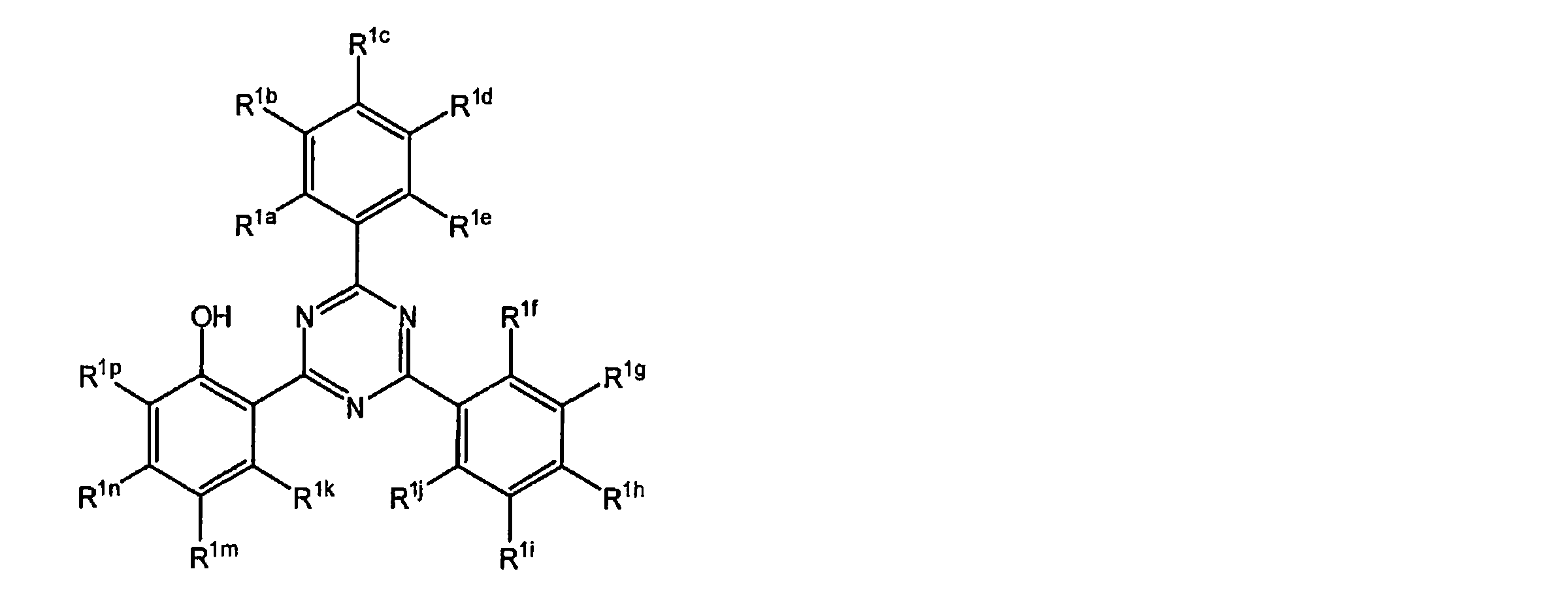
[R1a、R1b、R1c、R1d、R1eは、互いに独立して、水素原子又はOHを除く1価の置換基を表し、置換基のうち少なくとも1つは、ハメット則のσp値が正である置換基を表す。また置換基同士で結合して環を形成しても良い。R1f、R1g、R1h、R1i、R1jは、互いに独立して、水素原子又はOHを除く1価の置換基を表す。また置換基同士で結合して環を形成しても良い。R1k、R1m、R1n、R1pは、互いに独立して、水素原子又は1価の置換基を表す。また置換基同士で結合して環を形成しても良い。]
一般式(1)
R1a、R1b、R1c、R1d、R1eは、互いに独立して、水素原子又はOHを除く1価の置換基を表し、置換基のうち少なくとも1つは、ハメット則のσp値が正である置換基を表す。
R1a、R1b、R1c、R1d、R1eが表す置換基のうち1~3個がハメット則のσp値が正である置換基を表すことが好ましく、1~2個がハメット則のσp値が正である置換基を表すことがより好ましい。
また、R1a、R1c、R1eのうち少なくとも1つが、ハメット則のσp値が正である置換基を表すことが好ましく、R1cがハメット則のσp値が正である置換基を表すことがより好ましい。
R1cがハメット則のσp値が正である置換基であり、R1a、R1b、R1d、R1eは水素原子を表すことがより好ましい。
R1cがハメット則のσp値が正である置換基を表す場合、電子求引性基によりLUMOが安定化されるため、励起寿命が短くなり、耐光性が向上するため好ましい。
R1a、R1b、R1c、R1d、R1eが表す置換基のうち1~3個がハメット則のσp値が正である置換基を表すことが好ましく、1~2個がハメット則のσp値が正である置換基を表すことがより好ましい。
また、R1a、R1c、R1eのうち少なくとも1つが、ハメット則のσp値が正である置換基を表すことが好ましく、R1cがハメット則のσp値が正である置換基を表すことがより好ましい。
R1cがハメット則のσp値が正である置換基であり、R1a、R1b、R1d、R1eは水素原子を表すことがより好ましい。
R1cがハメット則のσp値が正である置換基を表す場合、電子求引性基によりLUMOが安定化されるため、励起寿命が短くなり、耐光性が向上するため好ましい。
前記一般式(1)における1価の置換基(以下Aとする)としては、例えば、ハロゲン原子(例えばフッ素原子、塩素原子、臭素原子、ヨウ素原子)、炭素数1~20のアルキル基(例えばメチル、エチル)、炭素数6~20のアリール基(例えばフェニル、ナフチル)、シアノ基、カルボキシル基、アルコキシカルボニル基(例えばメトキシカルボニル)、アリールオキシカルボニル基(例えばフェノキシカルボニル)、置換又は無置換のカルバモイル基(例えばカルバモイル、N-フェニルカルバモイル、N,N-ジメチルカルバモイル)、アルキルカルボニル基(例えばアセチル)、アリールカルボニル基(例えばベンゾイル)、ニトロ基、置換又は無置換のアミノ基(例えばアミノ、ジメチルアミノ、アニリノ、置換スルホアミノ基)、アシルアミノ基(例えばアセトアミド、エトキシカルボニルアミノ)、スルホンアミド基(例えばメタンスルホンアミド)、イミド基(例えばスクシンイミド、フタルイミド)、イミノ基(例えばベンジリデンアミノ)、ヒドロキシ基、炭素数1~20のアルコキシ基(例えばメトキシ)、アリールオキシ基(例えばフェノキシ)、アシルオキシ基(例えばアセトキシ)、アルキルスルホニルオキシ基(例えばメタンスルホニルオキシ)、アリールスルホニルオキシ基(例えばベンゼンスルホニルオキシ)、スルホ基、置換又は無置換のスルファモイル基(例えばスルファモイル、N-フェニルスルファモイル)、アルキルチオ基(例えばメチルチオ)、アリールチオ基(例えばフェニルチオ)、チオシアネート基、アルキルスルホニル基(例えばメタンスルホニル)、アリールスルホニル基(例えばベンゼンスルホニル)、炭素数6~20のヘテロ環基(例えばピリジル、モルホリノ)などを挙げることができる。
また、置換基は更に置換されていても良く、置換基が複数ある場合は、同じでも異なっても良い。その際、置換基の例としては、上述の1価の置換基Aを挙げることができる。また置換基同士で結合して環を形成しても良い。
また、置換基は更に置換されていても良く、置換基が複数ある場合は、同じでも異なっても良い。その際、置換基の例としては、上述の1価の置換基Aを挙げることができる。また置換基同士で結合して環を形成しても良い。
置換基同士で結合して形成される環としては、ベンゼン環、ピリジン環、ピラジン環、ピリミジン環、トリアジン環、ピリダジン環、ピロール環、ピラゾール環、イミダゾール環、トリアゾール環、オキサゾール環、オキサジアゾール環、チアゾール環、チアジアゾール環、フラン環、チオフェン環、セレノフェン環、シロール環、ゲルモール環、ホスホール環等が挙げられる。
前記一般式(1)における1価の置換基としては、ハロゲン原子、置換又は無置換の炭素数1~20のアルキル基、シアノ基、カルボキシル基、置換又は無置換のアルコキシカルボニル基、置換又は無置換のカルバモイル基、置換又は無置換のアルキルカルボニル基、ニトロ基、置換又は無置換のアミノ基、ヒドロキシ基、置換又は無置換の炭素数1~20のアルコキシ基、置換又は無置換のアリールオキシ基、置換又は無置換のスルファモイル基、チオシアネート基、又は置換又は無置換のアルキルスルホニル基が好ましく、ORU(Ruは、水素原子又は1価の置換基を表す。)、アルキル基、アミド基がより好ましく、ORu、アルキル基が更に好ましい。
Ruは、水素原子又は1価の置換基を表し、1価の置換基としては前記置換基Aを挙げることができる。中でも炭素数1~20の直鎖又は分岐鎖アルキル基を表すことが好ましい。炭素数1~6の直鎖又は分岐鎖アルキル基が更に好ましく、炭素数1~6の直鎖又は分岐鎖アルキル基としては、メチル、エチル、n-プロピル、i-プロピル、n-ブチル、i-ブチル、s-ブチル、t-ブチル、n-ペンチル、i-ペンチル、t-ペンチル、n-ヘキシル、i-ヘキシル、t-ヘキシル、n-オクチル、t-オクチル、i-オクチルを挙げることができ、メチル又はエチルが好ましく、メチルが特に好ましい。
Ruは、水素原子又は1価の置換基を表し、1価の置換基としては前記置換基Aを挙げることができる。中でも炭素数1~20の直鎖又は分岐鎖アルキル基を表すことが好ましい。炭素数1~6の直鎖又は分岐鎖アルキル基が更に好ましく、炭素数1~6の直鎖又は分岐鎖アルキル基としては、メチル、エチル、n-プロピル、i-プロピル、n-ブチル、i-ブチル、s-ブチル、t-ブチル、n-ペンチル、i-ペンチル、t-ペンチル、n-ヘキシル、i-ヘキシル、t-ヘキシル、n-オクチル、t-オクチル、i-オクチルを挙げることができ、メチル又はエチルが好ましく、メチルが特に好ましい。
前記一般式(1)で表される紫外線吸収剤において、R1nが1価の置換基を表すことが好ましく、R1nがORuを表すことがより好ましい。R1nがORUを表し、R1k、R1m、R1pがいずれも水素原子を表すことが更に好ましい。モル吸光係数が大きくなり、遮蔽効果が増すためである。
前記一般式(1)におけるハメット則のσp値が正である置換基として、好ましくは、σp値が0.1~1.2の電子求引性基である。σp値が0.1以上の電子求引性基の具体例としては、COORr(Rrは、水素原子又は1価の置換基を表す。)、CONRs
2(Rsは、水素原子又は1価の置換基を表す。)、CN、ハロゲン原子、NO2、SO2Rt(Rtは、水素原子又は1価の置換基を表す。)、SO3M(Mは、水素原子又はアルカリ金属を表す。)、アシル基、ホルミル基、アシルオキシ基、アシルチオ基、アルキルオキシカルボニル基、アリールオキシカルボニル基、ジアルキルホスホノ基、ジアリールホスホノ基、ジアルキルホスフィニル基、ジアリールホスフィニル基、ホスホリル基、アルキルスルフィニル基、アリールスルフィニル基、アシルチオ基、スルファモイル基、チオシアネート基、チオカルボニル基、イミノ基、N原子で置換したイミノ基、カルボキシ基(又はその塩)、少なくとも2つ以上のハロゲン原子で置換されたアルキル基(例えばCF3)、少なくとも2つ以上のハロゲン原子で置換されたアルコキシ基、少なくとも2つ以上のハロゲン原子で置換されたアリールオキシ基、アシルアミノ基、少なくとも2つ以上のハロゲン原子で置換されたアルキルアミノ基、少なくとも2つ以上のハロゲン原子で置換されたアルキルチオ基、σp値が0.2以上の他の電子求引性基で置換されたアリール基、ヘテロ環基、ハロゲン原子、アゾ基、セレノシアネート基などが挙げられる。ハメットのσp値については、Hansch,C.;Leo,A.;Taft,R.W.Chem.Rev.1991,91,165-195に詳しく記載されている。
前記一般式(1)におけるハメット則のσp値が正である置換基として、より好ましくは、COORr、CONRs
2、CN、CF3、ハロゲン原子、NO2、SO2Rt、SO3Mである[Rr、Rsは、それぞれ独立に水素原子又は1価の置換基を表す。Mは、水素原子又はアルカリ金属を表す]。この中でもCOORr又はCNがより好ましく、COORr、であることが更に好ましい。優れた耐光性と溶解性を有するためである。
Rrとしては水素原子又は1価の置換基を表し、1価の置換基としては前記置換基Aを挙げることができる。中でも炭素数1~20の直鎖又は分岐鎖アルキル基が好ましく、炭素数1~6の直鎖又は分岐鎖アルキル基がより好ましい。炭素数1~6の直鎖又は分岐鎖アルキル基としては、メチル、エチル、n-プロピル、i-プロピル、n-ブチル、i-ブチル、s-ブチル、t-ブチル、n-ペンチル、i-ペンチル、t-ペンチル、n-ヘキシル、i-ヘキシル、t-ヘキシル、t-オクチル、i-オクチル、n-オクチルを挙げることができ、メチル又はエチルが好ましく、メチルが特に好ましい。
前記一般式(1)で表される紫外線吸収剤において、R1cがCOORr、CONRs 2、CN、CF3、ハロゲン原子、NO2、SO2Rt、SO3Mのいずれかであることが好ましくCOORr又はCNであることがより好ましい。耐光性の観点からはR1cはCNであることが好ましい。
Rrとしては水素原子又は1価の置換基を表し、1価の置換基としては前記置換基Aを挙げることができる。中でも炭素数1~20の直鎖又は分岐鎖アルキル基が好ましく、炭素数1~6の直鎖又は分岐鎖アルキル基がより好ましい。炭素数1~6の直鎖又は分岐鎖アルキル基としては、メチル、エチル、n-プロピル、i-プロピル、n-ブチル、i-ブチル、s-ブチル、t-ブチル、n-ペンチル、i-ペンチル、t-ペンチル、n-ヘキシル、i-ヘキシル、t-ヘキシル、t-オクチル、i-オクチル、n-オクチルを挙げることができ、メチル又はエチルが好ましく、メチルが特に好ましい。
前記一般式(1)で表される紫外線吸収剤において、R1cがCOORr、CONRs 2、CN、CF3、ハロゲン原子、NO2、SO2Rt、SO3Mのいずれかであることが好ましくCOORr又はCNであることがより好ましい。耐光性の観点からはR1cはCNであることが好ましい。
また、本発明において、R1f、R1g、R1h、R1i、R1j、R1k、R1m、R1n、R1pのうち少なくとも1つが、前記ハメット則のσp値が正である置換基を表すことがより好ましく、R1f、R1g、R1h、R1i、R1jのうち少なくとも1つが、前記ハメット則のσp値が正である置換基を表すことがより好ましく、R1hが前記ハメット則のσp値が正である置換基を表すことが更に好ましい。
R1c及びR1hが共に前記ハメット則のσp値が正である置換基を表すことが特に好ましい。
優れた耐光性を有するためである。
R1c及びR1hが共に前記ハメット則のσp値が正である置換基を表すことが特に好ましい。
優れた耐光性を有するためである。
前記一般式(1)で表される紫外線吸収剤はpKaが-5.0~-7.0の範囲であることが好ましい。更に-5.2~-6.5の範囲であることがより好ましく、-5.4~-6.0の範囲であることが特に好ましい。
前記一般式(1)で表される紫外線吸収剤の具体例を以下に示すが、本発明はこれに限定されない。
なお、下記の具体例中Meはメチル基を表し、Phはフェニル基を表し、-C6H13はn-ヘキシルを表す。
なお、下記の具体例中Meはメチル基を表し、Phはフェニル基を表し、-C6H13はn-ヘキシルを表す。

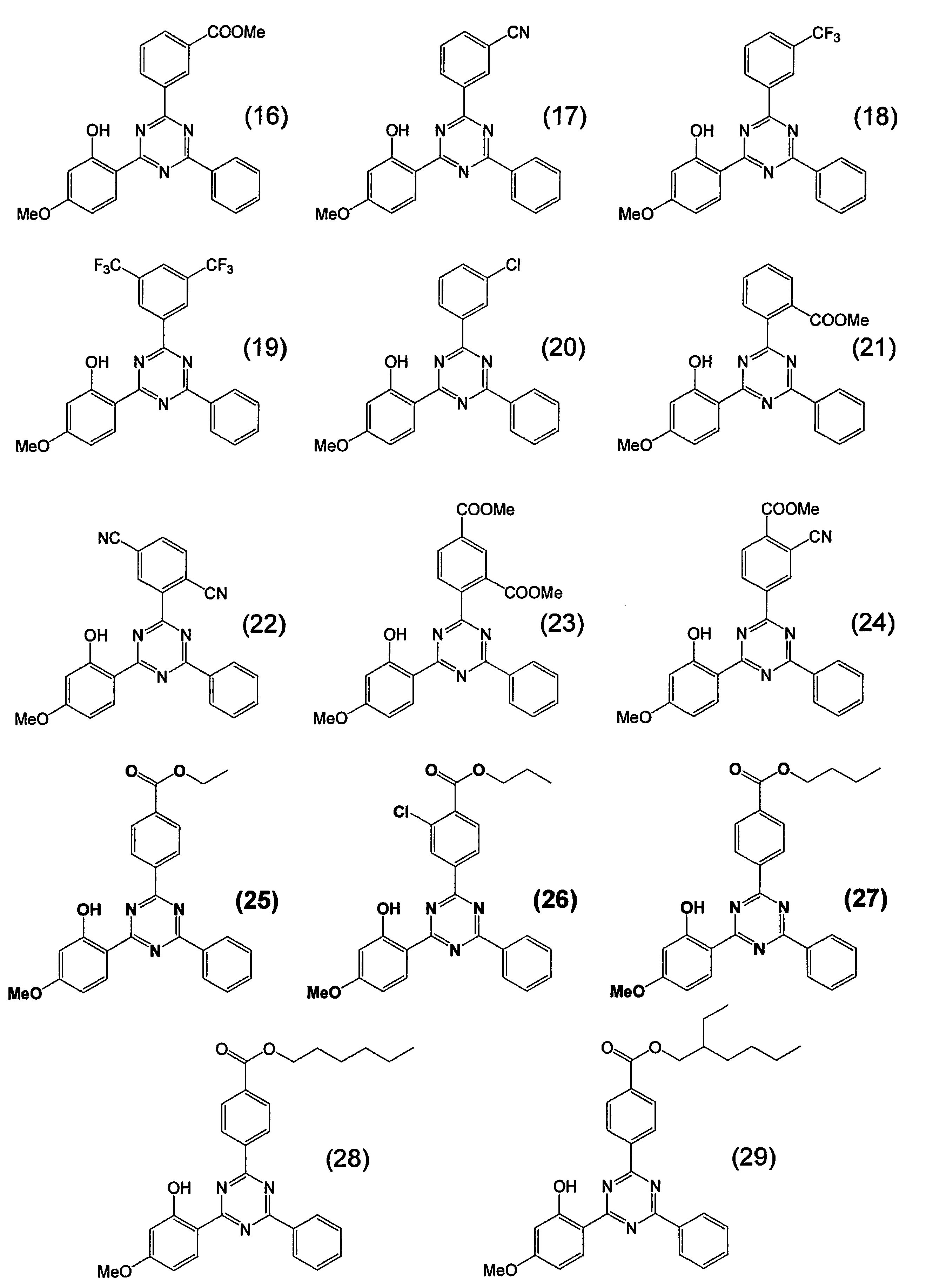
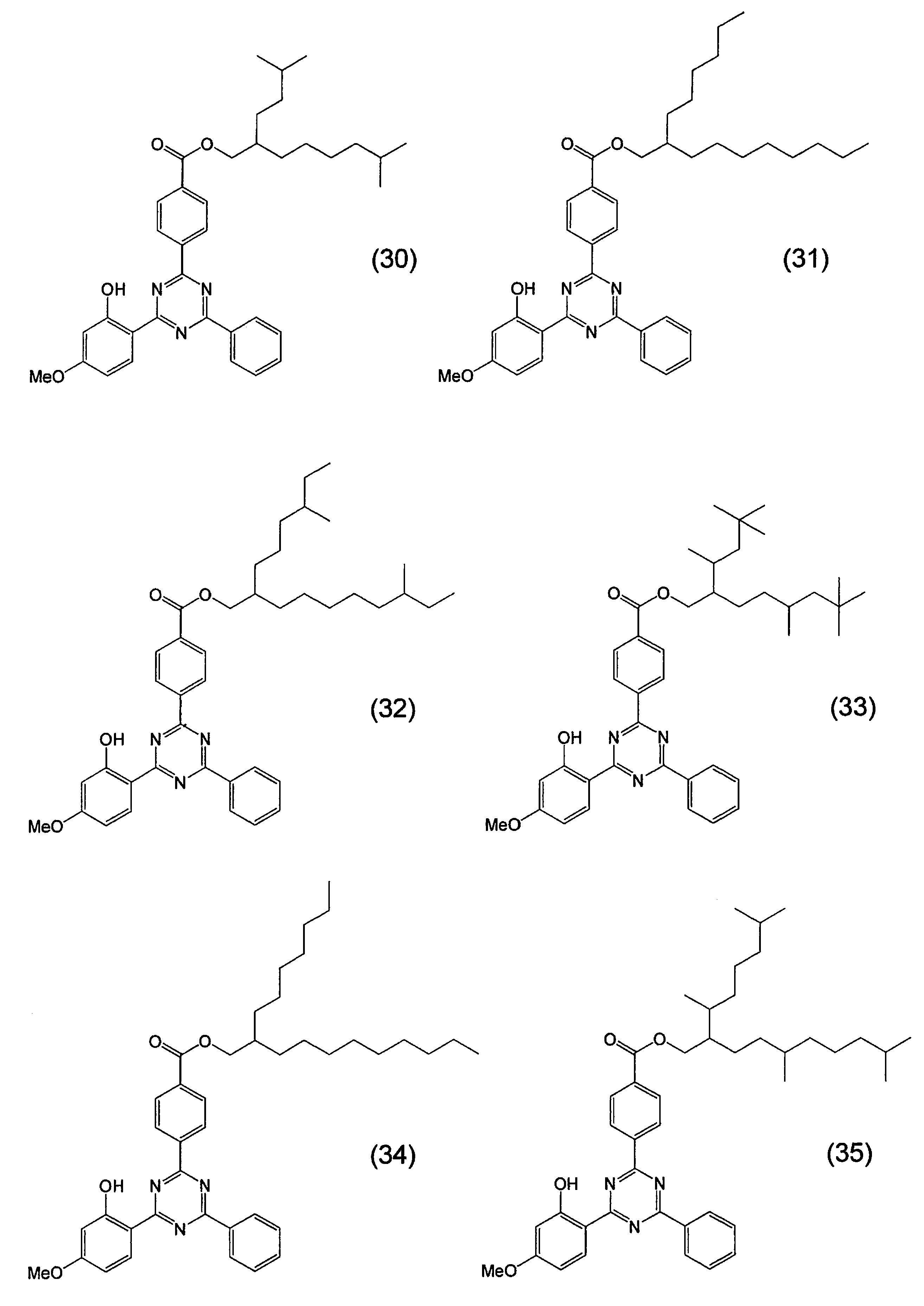


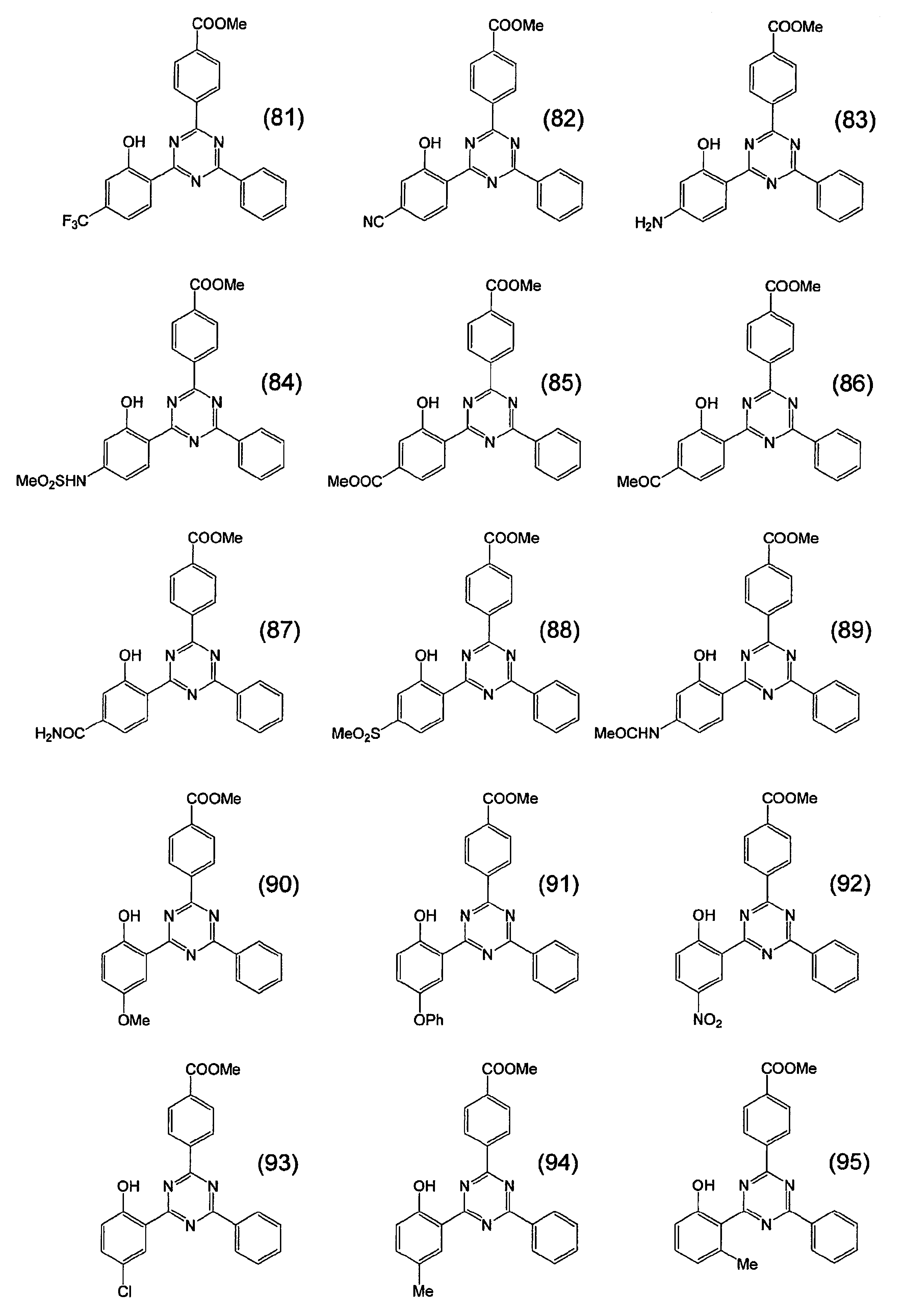

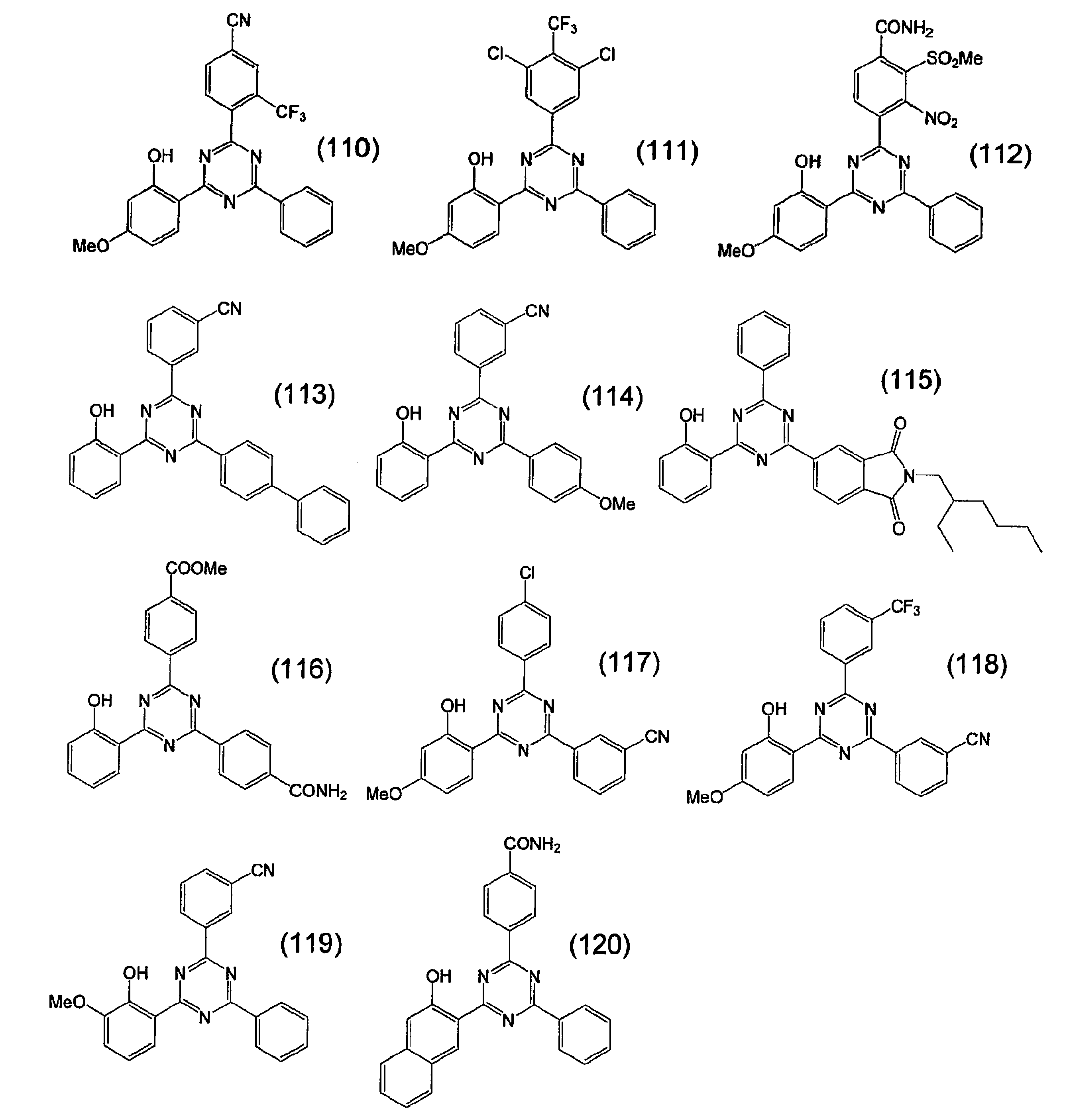
前記一般式(1)で表される紫外線吸収剤は、構造とその置かれた環境によって互変異性体を取り得る。本発明においては代表的な形の一つで記述しているが、本発明の記述と異なる互変異性体も本発明の化合物に含まれる。
前記一般式(1)で表される紫外線吸収剤は、同位元素(例えば、2H、3H、13C、15N、17O、18Oなど)を含有していてもよい。
前記一般式(1)で表される紫外線吸収剤は、任意の方法で合成することができる。
例えば、公知の特許文献や非特許文献、例えば、特開平7-188190号公報、特開平11-315072号公報、特開2001-220385号公報、「染料と薬品」第40巻12号(1995)の325~339ページなどを参考にして合成できる。具体的には、例示化合物(19)は4-メトキシサリチルアミドと3,5-ビス(トリフルオロメチル)ベンゾイルクロリドとベンズアミジン塩酸塩とを反応させることにより合成できる。
例えば、公知の特許文献や非特許文献、例えば、特開平7-188190号公報、特開平11-315072号公報、特開2001-220385号公報、「染料と薬品」第40巻12号(1995)の325~339ページなどを参考にして合成できる。具体的には、例示化合物(19)は4-メトキシサリチルアミドと3,5-ビス(トリフルオロメチル)ベンゾイルクロリドとベンズアミジン塩酸塩とを反応させることにより合成できる。
本発明で用いる紫外線吸収剤は、一般式(1)で表される紫外線吸収剤からなる。本発明の一般式(I)で表される化合物は特定の位置にハメット則のσp値が正である置換基を有するため、電子求引性基によりLUMOが安定化されるため、励起寿命が短くなり、優れた耐光性を有するという特徴を有する。紫外線吸収剤として用いた際にも、既知のトリアジン系化合物を用いた場合は、長時間使用した場合は分解して黄変するなど悪影響を及ぼす。
それに対して、本発明の一般式(I)で表される化合物は優れた耐光性を有するため長時間使用した場合でも分解せず黄変することがない。
それに対して、本発明の一般式(I)で表される化合物は優れた耐光性を有するため長時間使用した場合でも分解せず黄変することがない。
前記一般式(I)で表される化合物は、一種のみ用いてもよく、二種以上を併用することもできる。
本発明で用いる紫外線吸収剤の使用形態は、いずれでも良い。例えば、液体分散物、溶液、樹脂組成物などが挙げられる。
本発明で用いる紫外線吸収剤の極大吸収波長は、特に限定されないが、好ましくは250~400nmであり、より好ましくは280~380nmである。半値幅は好ましくは20~100nmであり、より好ましくは40~80nmである。
本発明で用いる紫外線吸収剤の使用形態は、いずれでも良い。例えば、液体分散物、溶液、樹脂組成物などが挙げられる。
本発明で用いる紫外線吸収剤の極大吸収波長は、特に限定されないが、好ましくは250~400nmであり、より好ましくは280~380nmである。半値幅は好ましくは20~100nmであり、より好ましくは40~80nmである。
本発明において規定される極大吸収波長及び半値幅は、当業者が容易に測定することができる。測定方法に関しては、例えば日本化学会編「第4版実験化学講座7分光II」(丸善,1992年)180~186ページなどに記載されている。具体的には、適当な溶媒に試料を溶解し、石英製又はガラス製のセルを用いて、試料用と対照用の2つのセルを使用して分光光度計によって測定される。用いる溶媒は、試料の溶解性と合わせて、測定波長領域に吸収を持たないこと、溶質分子との相互作用が小さいこと、揮発性があまり著しくないこと等が要求される。上記条件を満たす溶媒であれば、任意のものを選択することができる。本発明においては、酢酸エチル(EtOAc)を溶媒に用いて測定を行うこととする。
本発明における化合物の極大吸収波長及び半値幅は、酢酸エチルを溶媒として、濃度約5×10⁻⁵mol・dm-3の溶液を調製し、光路長10mmの石英セルを使用して測定した値を使用する。
スペクトルの半値幅に関しては、例えば日本化学会編「第4版実験化学講座3 基本操作III」(丸善、1991年)154ページなどに記載がある。なお、上記成書では波数目盛りで横軸を取った例で半値幅の説明がなされているが、本発明における半値幅は波長目盛りで軸を取った場合の値を用いることとし、半値幅の単位はnmである。具体的には、極大吸収波長における吸光度の1/2の吸収帯の幅を表し、吸収スペクトルの形を表す値として用いられる。半値幅が小さいスペクトルはシャープなスペクトルであり、半値幅が大きいスペクトルはブロードなスペクトルである。ブロードなスペクトルを与える紫外線吸収化合物は、極大吸収波長から長波側の幅広い領域にも吸収を有するので、黄色味着色がなく長波紫外線領域を効果的に遮蔽するためには、半値幅が小さいスペクトルを有する紫外線吸収化合物の方が好ましい。
時田澄男著「化学セミナー9 カラーケミストリー」(丸善、1982年)154~155ページに記載されているように、光の吸収の強さすなわち振動子強度はモル吸光係数の積分に比例し、吸収スペクトルの対称性がよいときは、振動子強度は極大吸収波長における吸光度と半値幅の積に比例する(但しこの場合の半値幅は波長目盛りで軸を取った値である)。このことは遷移モーメントの値が同じとした場合、半値幅が小さいスペクトルを有する化合物は極大吸収波長における吸光度が大きくなることを意味している。このような紫外線吸収化合物は少量使用するだけで極大吸収波長周辺の領域を効果的に遮蔽できるメリットがあるが、波長が極大吸収波長から少し離れると急激に吸光度が減少するために、幅広い領域を遮蔽することができない。
紫外線吸収剤は、極大吸収波長におけるモル吸光係数が20000以上であることが好ましく、30000以上であることがより好ましく、50000以上であることが特に好ましい。20000以上であれば、紫外線吸収剤の質量当たりの吸収効率が十分得られるため、紫外線領域を完全に吸収するための紫外線吸収剤の使用量を低減できる。これは皮膚刺激性や生体内への蓄積を防ぐ観点、及びブリードアウトが生じにくい点から好ましい。極なお、モル吸光係数については、例えば日本化学会編「新版実験化学講座9 分析化学[II]」(丸善、1977年)244ページなどに記載されている定義を用いたものであり、上述した極大吸収波長及び半値幅を求める際に合わせて求めることができる。
本発明で用いる紫外線吸収剤は、紫外線吸収剤が分散媒体に分散された分散物の状態でも使用できる。本発明で用いる紫外線吸収剤を分散する媒体はいずれのものであってもよい。例えば、水、有機溶剤、樹脂、樹脂の溶液などが挙げられる。これらを単独で用いてもよいし、組み合わせて使用してもよい。
一般式(2)で表される紫外線吸収剤
一般式(2)
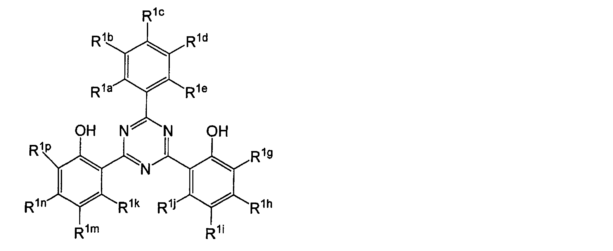
[R1a、R1c及びR1eは、水素原子を表す。R1b及びR1dは、互いに独立して、水素原子又はハメット則のσp値が正である置換基を表し、少なくとも1つは、ハメット則のσp値が正である置換基を表す。R1g、R1h、R1i、R1j、R1k、R1m、R1n及びR1pは、互いに独立して、水素原子又は1価の置換基を表す。また置換基同士で結合して環を形成しても良い。]
一般式(2)
一般式(2)で表される紫外線吸収剤は、R1a、R1c及びR1eが水素原子を表し、かつ、R1b及びR1dは、互いに独立して、水素原子又はハメット則のσp値が正である置換基を表し、R1b及びR1dの少なくとも1つが、ハメット則のσp値が正である置換基を表すことにより、電子求引性基によりLUMOが安定化されるため、励起寿命が短くなる。また、化合物構造の対称性がくずれることとなり、優れた耐光性及び溶媒に対する高溶解性を有する。
前記一般式(2)における1価の置換基(以下Aとする)としては、例えば、ハロゲン原子(例えばフッ素原子、塩素原子、臭素原子、ヨウ素原子)、炭素数1~20のアルキル基(例えばメチル、エチル)、炭素数6~20のアリール基(例えばフェニル、ナフチル)、シアノ基、カルボキシル基、アルコキシカルボニル基(例えばメトキシカルボニル)、アリールオキシカルボニル基(例えばフェノキシカルボニル)、置換又は無置換のカルバモイル基(例えばカルバモイル、N-フェニルカルバモイル、N,N-ジメチルカルバモイル)、アルキルカルボニル基(例えばアセチル)、アリールカルボニル基(例えばベンゾイル)、ニトロ基、置換又は無置換のアミノ基(例えばアミノ、ジメチルアミノ、アニリノ、置換スルホアミノ)、アシルアミノ基(例えばアセトアミド、エトキシカルボニルアミノ)、スルホンアミド基(例えばメタンスルホンアミド)、イミド基(例えばスクシンイミド、フタルイミド)、イミノ基(例えばベンジリデンアミノ)、ヒドロキシ基、炭素数1~20のアルコキシ基(例えばメトキシ)、アリールオキシ基(例えばフェノキシ)、アシルオキシ基(例えばアセトキシ)、アルキルスルホニルオキシ基(例えばメタンスルホニルオキシ)、アリールスルホニルオキシ基(例えばベンゼンスルホニルオキシ)、スルホ基、置換又は無置換のスルファモイル基(例えばスルファモイル、N-フェニルスルファモイル)、アルキルチオ基(例えばメチルチオ)、アリールチオ基(例えばフェニルチオ)、チオシアネート基、アルキルスルホニル基(例えばメタンスルホニル)、アリールスルホニル基(例えばベンゼンスルホニル)、炭素数6~20のヘテロ環基(例えばピリジル、モルホリノ)などを挙げることができる。
また、置換基は更に置換されていても良く、置換基が複数ある場合は、同じでも異なっても良い。その際、置換基の例としては、上述の1価の置換基Aを挙げることができる。また置換基同士で結合して環を形成しても良い。
また、置換基は更に置換されていても良く、置換基が複数ある場合は、同じでも異なっても良い。その際、置換基の例としては、上述の1価の置換基Aを挙げることができる。また置換基同士で結合して環を形成しても良い。
置換基同士で結合して形成される環としては、ベンゼン環、ピリジン環、ピラジン環、ピリミジン環、トリアジン環、ピリダジン環、ピロール環、ピラゾール環、イミダゾール環、トリアゾール環、オキサゾール環、オキサジアゾール環、チアゾール環、チアジアゾール環、フラン環、チオフェン環、セレノフェン環、シロール環、ゲルモール環、ホスホール環等が挙げられる。
前記一般式(2)における1価の置換基としては、ハロゲン原子、置換又は無置換の炭素数1~20のアルキル基、シアノ基、カルボキシル基、置換又は無置換のアルコキシカルボニル基、置換又は無置換のカルバモイル基、置換又は無置換のアルキルカルボニル基、ニトロ基、置換又は無置換のアミノ基、ヒドロキシ基、炭素数1~20のアルコキシ基、置換又は無置換のアリールオキシ基、置換又は無置換のスルファモイル基、チオシアネート基、又は置換又は無置換のアルキルスルホニル基であり、置換基を有する場合の置換基がハロゲン原子、炭素数1~20のアルキル基、シアノ基、カルボキシル基、アルコキシカルボニル基、カルバモイル基、アルキルカルボニル基、ニトロ基、アミノ基、ヒドロキシ基、炭素数1~20のアルコキシ基、アリールオキシ基、スルファモイル基、チオシアネート基、又はアルキルスルホニル基が挙げられる。
R1b及びR1dは、互いに独立して、水素原子又はハメット則のσp値が正である置換基を表し、少なくとも1つは、ハメット則のσp値が正である置換基を表す。
R1b及びR1dの少なくとも1つが、ハメット則のσp値が正である置換基であることにより、耐光性に優れるだけでなく、溶媒に対する溶解性及び耐熱性にも優れた効果を示す。
溶剤溶解性とは、酢酸エチル、メチルエチルケトン、トルエンなどの有機溶剤への溶解性を意味し、酢酸エチル、メチルエチルケトン、トルエンなどの有機溶剤に対し、10質量%以上溶解することが好ましく、30質量%以上溶解することがより好ましい。
R1b及びR1dの少なくとも1つが、ハメット則のσp値が正である置換基であることにより、耐光性に優れるだけでなく、溶媒に対する溶解性及び耐熱性にも優れた効果を示す。
溶剤溶解性とは、酢酸エチル、メチルエチルケトン、トルエンなどの有機溶剤への溶解性を意味し、酢酸エチル、メチルエチルケトン、トルエンなどの有機溶剤に対し、10質量%以上溶解することが好ましく、30質量%以上溶解することがより好ましい。
前記一般式(2)におけるハメット則のσp値が正である置換基として、好ましくは、σp値が0.1~1.2の電子求引性基であり、さらに好ましくは、0.3~1.2の電子求引性基である。σp値が0.1以上の電子求引性基の具体例としては、COORr(Rrは、水素原子又は1価の置換基を表し、水素原子、アルキル基が挙げられ、好ましくはアルキル基である。)、CONRs
2(Rsは、水素原子又は1価の置換基を表し、例えば、水素原子、炭素数1~20のアルキル基、炭素数6~20のアリール基、炭素数6~20のヘテロ環基が挙げられ、好ましくは水素原子である。)、シアノ基、ハロゲン原子、ニトロ基、SO3M(Mは、水素原子又はアルカリ金属を表す。)、アシル基、ホルミル基、アシルオキシ基、アシルチオ基、アルキルオキシカルボニル基、アリールオキシカルボニル基、ジアルキルホスホノ基、ジアリールホスホノ基、ジアルキルホスフィニル基、ジアリールホスフィニル基、ホスホリル基、アルキルスルフィニル基、アリールスルフィニル基、アルキルスルホニル基、アリールスルホニル基、アシルチオ基、スルファモイル基、チオシアネート基、チオカルボニル基、イミノ基、N原子で置換したイミノ基、カルボキシ基(又はその塩)、少なくとも2つ以上のハロゲン原子で置換されたアルキル基(例えばCF3)、少なくとも2つ以上のハロゲン原子で置換されたアルコキシ基、少なくとも2つ以上のハロゲン原子で置換されたアリールオキシ基、アシルアミノ基、少なくとも2つ以上のハロゲン原子で置換されたアルキルアミノ基、少なくとも2つ以上のハロゲン原子で置換されたアルキルチオ基、σp値が0.2以上の他の電子求引性基で置換されたアリール基、ヘテロ環基、ハロゲン原子、アゾ基、セレノシアネート基などが挙げられる。ハメットのσp値については、Hansch,C.;Leo,A.;Taft,R.W.Chem.Rev.1991,91,165-195に詳しく記載されている。
前記一般式(2)におけるハメット則のσp値が正である置換基として、より好ましくは、COORr、CONRs
2、シアノ基、CF3、ハロゲン原子、ニトロ基、SO3Mである[Rr、Rsは、互いに独立して、水素原子又は1価の置換基を表す。Mは、水素原子又はアルカリ金属を表す]。1価の置換基としては前記置換基Aを挙げることができる。前記一般式(2)におけるハメット則のσp値が正である置換基として、より好ましくは、COORr又はシアノ基であり、COORrであることが更に好ましい。ハメット則のσp値が正である置換基がシアノ基である場合、優れた耐光性を示すためである。また、ハメット則のσp値が正である置換基がCOORrである場合、優れた溶解性を示するためである。
Rrは水素原子又はアルキル基を表すことが好ましく、炭素数1~20の直鎖又は分岐鎖アルキル基がより好ましく、炭素数1~15の直鎖又は分岐鎖アルキル基が更に好ましい。
Rrは水素原子又はアルキル基を表すことが好ましく、炭素数1~20の直鎖又は分岐鎖アルキル基がより好ましく、炭素数1~15の直鎖又は分岐鎖アルキル基が更に好ましい。
Rrは、溶媒に対する溶解性の観点からは、炭素数5~15の分岐鎖アルキル基がより好ましい。
分岐鎖アルキル基は2級炭素原子又は3級炭素原子を有し、2級炭素原子又は3級炭素原子を1~5個含むことが好ましく、1~3個含むことが好ましく、1又は2個含むことが好ましく、2級炭素原子及び3級炭素原子を1又は2個含むことがより好ましい。また、不斉炭素を1~3個含むことが好ましい。
Rrは、溶媒に対する溶解性の観点からは、2級炭素原子及び3級炭素原子を1又は2個含み、不斉炭素を1又は2個含む炭素数5~15の分岐鎖アルキル基であることが特に好ましい。
これは、化合物構造の対称性がくずれ、溶解性が向上するためである。
分岐鎖アルキル基は2級炭素原子又は3級炭素原子を有し、2級炭素原子又は3級炭素原子を1~5個含むことが好ましく、1~3個含むことが好ましく、1又は2個含むことが好ましく、2級炭素原子及び3級炭素原子を1又は2個含むことがより好ましい。また、不斉炭素を1~3個含むことが好ましい。
Rrは、溶媒に対する溶解性の観点からは、2級炭素原子及び3級炭素原子を1又は2個含み、不斉炭素を1又は2個含む炭素数5~15の分岐鎖アルキル基であることが特に好ましい。
これは、化合物構造の対称性がくずれ、溶解性が向上するためである。
一方、紫外線吸収能の観点からは、炭素数1~6の直鎖又は分岐鎖アルキル基がより好ましい。
炭素数1~6の直鎖又は分岐鎖アルキル基としては、メチル、エチル、n-プロピル、i-プロピル、n-ブチル、i-ブチル、s-ブチル、t-ブチル、n-ペンチル、i-ペンチル、t-ペンチル、n-ヘキシル、i-ヘキシル、t-ヘキシル、n-オクチル、t-オクチル、i-オクチルを挙げることができ、メチル又はエチルが好ましく、メチルが特に好ましい。
炭素数1~6の直鎖又は分岐鎖アルキル基としては、メチル、エチル、n-プロピル、i-プロピル、n-ブチル、i-ブチル、s-ブチル、t-ブチル、n-ペンチル、i-ペンチル、t-ペンチル、n-ヘキシル、i-ヘキシル、t-ヘキシル、n-オクチル、t-オクチル、i-オクチルを挙げることができ、メチル又はエチルが好ましく、メチルが特に好ましい。
また、本発明において、R1g、R1h、R1i、R1j、R1k、R1m、R1n及びR1pが1価の置換基を表す場合は、R1g、R1h、R1i、R1j、R1k、R1m、R1n及びR1pのうち少なくとも1つが、前記ハメット則のσp値が正である置換基を表すことがより好ましく、R1g、R1h、R1i及びR1jのうち少なくとも1つが、前記ハメット則のσp値が正(好ましくは0.1~1.2)である置換基を表すことがより好ましく、R1hが前記ハメット則のσp値が正である置換基を表すことが更に好ましい。R1b又はR1d、及びR1hが前記ハメット則のσp値が正(好ましくは0.1~1.2)である置換基を表すことが特に好ましい。優れた耐光性を有するためである。
本発明において、R1h又はR1nがそれぞれ独立に水素原子、COORr、CONRs 2、シアノ基、CF3、ハロゲン原子、ニトロ基、SO3Mのいずれかであることが好ましく、R1h又はR1nが水素原子であることがより好ましく、R1h及びR1nが水素原子であることが更に好ましく、R1g、R1h、R1i、R1j、R1k、R1m、R1n及びR1pが水素原子を表すことが特に好ましい。優れた耐光性を示すためである。
本発明において、R1h又はR1nがそれぞれ独立に水素原子、COORr、CONRs 2、シアノ基、CF3、ハロゲン原子、ニトロ基、SO3Mのいずれかであることが好ましく、R1h又はR1nが水素原子であることがより好ましく、R1h及びR1nが水素原子であることが更に好ましく、R1g、R1h、R1i、R1j、R1k、R1m、R1n及びR1pが水素原子を表すことが特に好ましい。優れた耐光性を示すためである。
前記一般式(2)で表される紫外線吸収剤において、R1b又はR1d、がハメット則のσp値が正(好ましくは0.1~1.2)である置換基であって、R1g、R1h、R1i、R1j、R1k、R1m、R1n及びR1pは水素原子を表すことが好ましく、R1b又はR1d、がCOORr、CONRs
2、シアノ基、CF3、ハロゲン原子、ニトロ基、SO3Mのいずれかであって、R1g、R1h、R1i、R1j、R1k、R1m、R1n及びR1pは水素原子であることがより好ましい。優れた耐光性を示すためである。
前記一般式(2)で表される紫外線吸収剤はpKaが-5.0~-7.0の範囲であることが好ましい。更に-5.2~-6.5の範囲であることがより好ましく、-5.4~-6.0の範囲であることが特に好ましい。
前記一般式(2)で表される紫外線吸収剤の具体例を以下に示すが、本発明はこれに限定されない。
なお、下記の具体例中Meはメチル基を表し、Phはフェニル基を表し、-C6H13はn-ヘキシルを表す。
なお、下記の具体例中Meはメチル基を表し、Phはフェニル基を表し、-C6H13はn-ヘキシルを表す。
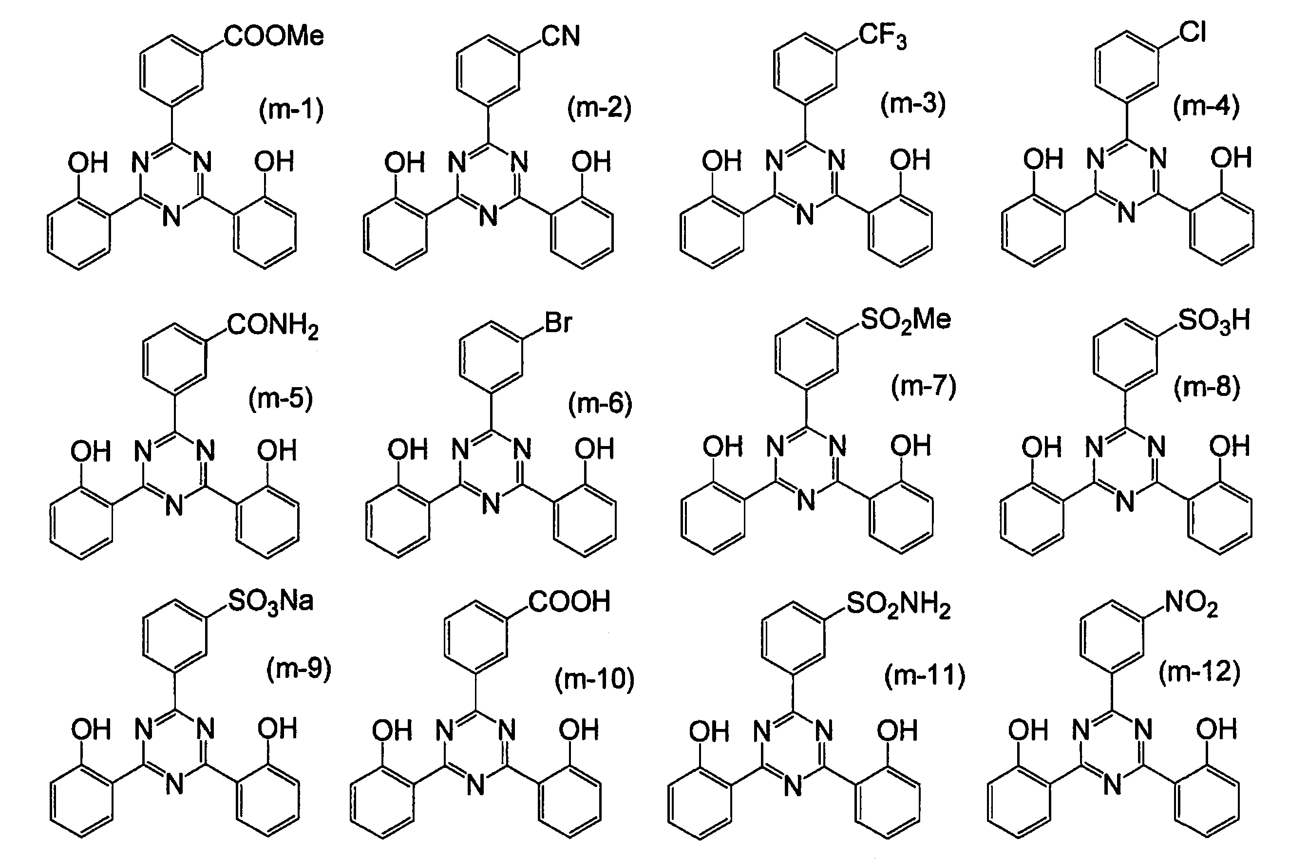
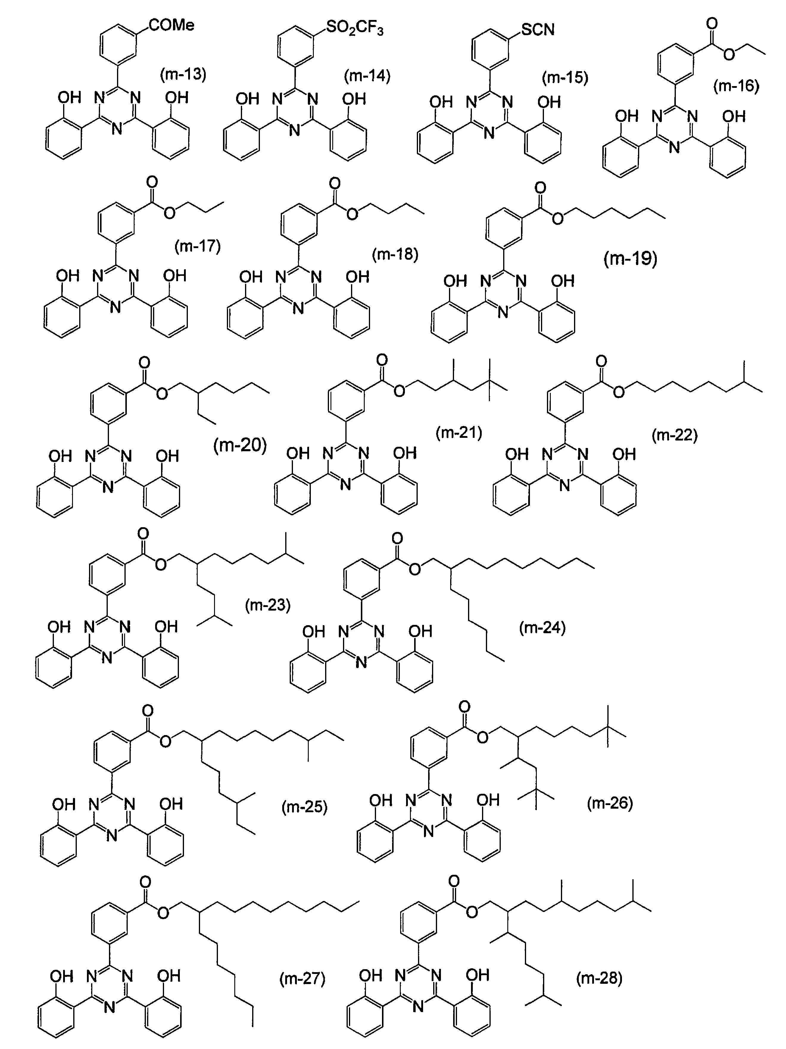
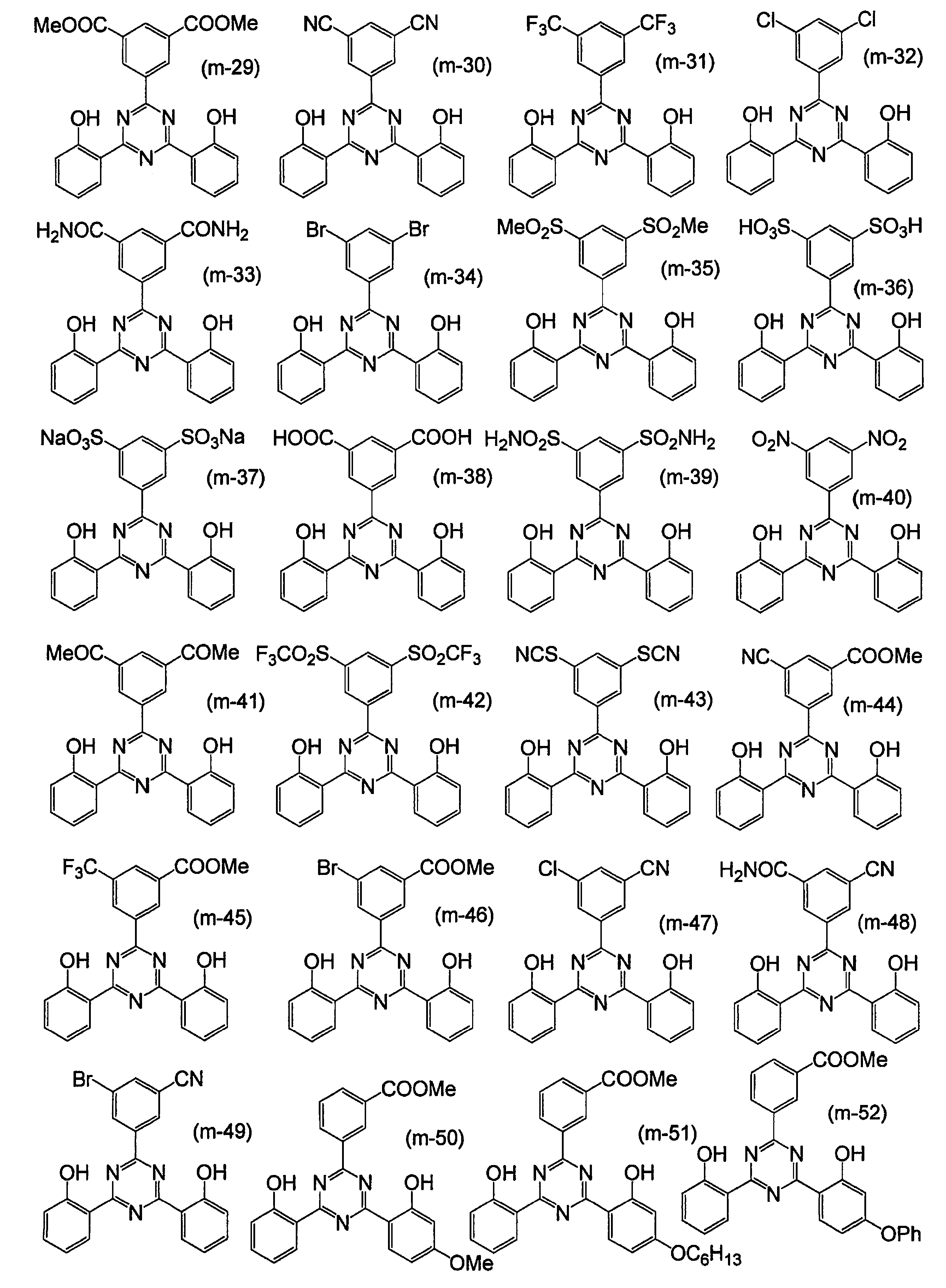
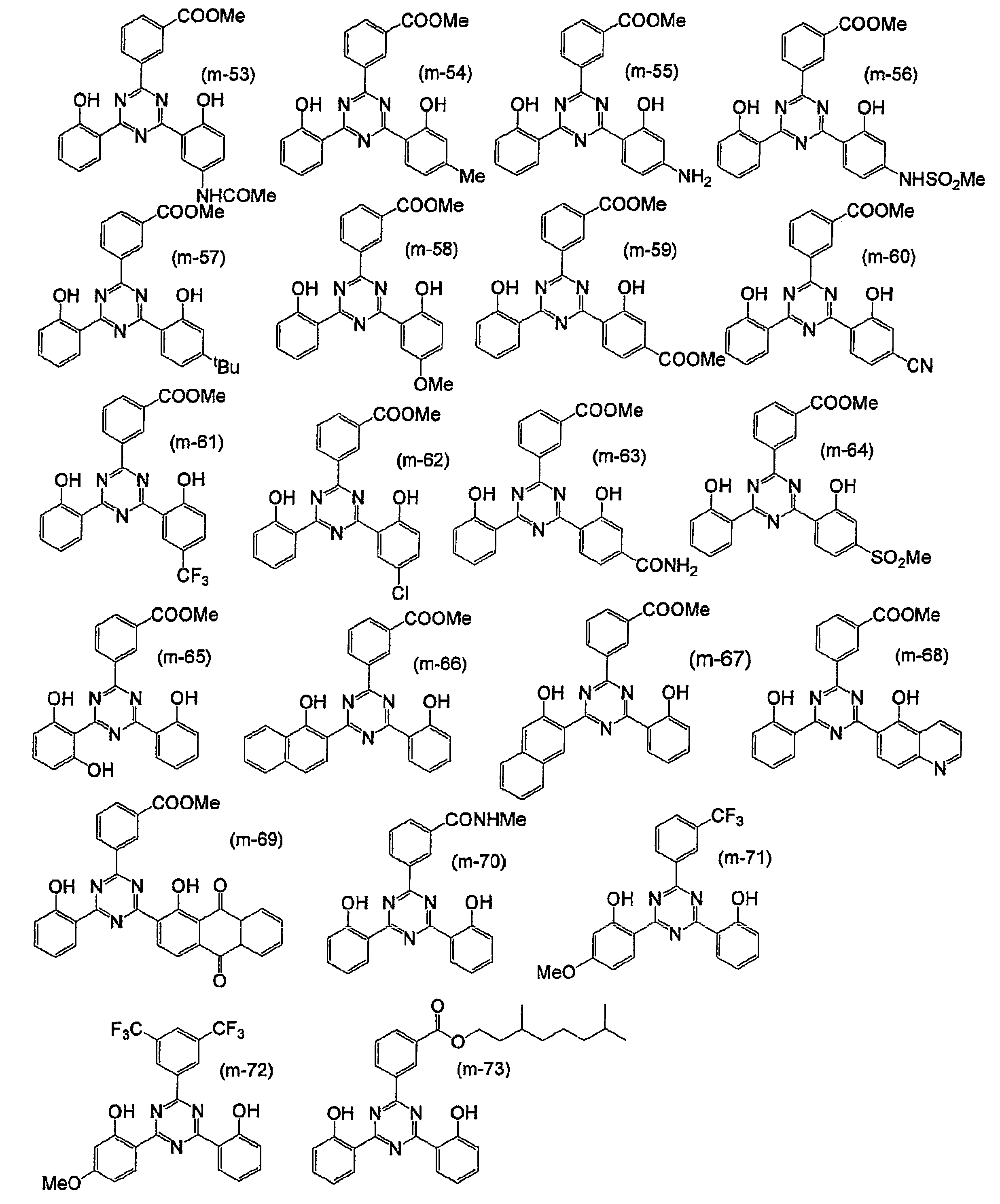
前記一般式(2)で表される紫外線吸収剤は、構造とその置かれた環境によって互変異性体を取り得る。本発明においては代表的な形の一つで記述しているが、本発明の記述と異なる互変異性体も本発明の化合物に含まれる。
前記一般式(2)で表される紫外線吸収剤は、同位元素(例えば、2H、3H、13C、15N、17O、18Oなど)を含有していてもよい。
前記一般式(2)で表される紫外線吸収剤は、任意の方法で合成することができる。例えば、公知の特許文献や非特許文献、例えば、特開平7-188190号公報、特開平11-315072、特開2001-220385号公報、「染料と薬品」第40巻12号(1995)の325~339ページなどを参考にして合成できる。具体的には、例示化合物(16)はサリチルアミドと3,5-ビス(トリフルオロメチル)ベンゾイル クロリドと2-ヒドロキシベンズアミジン塩酸塩とを反応させることにより合成できる。また、サリチルアミドとサリチル酸と3,5-ビス(トリフルオロメチル)ベンズアミジン塩酸塩とを反応させることによっても合成できる。
その他については、一般式(1)で表される紫外線吸収剤の記載を参酌できる。
その他については、一般式(1)で表される紫外線吸収剤の記載を参酌できる。
バインダー
本発明におけるコーティング層に含まれるバインダーは、その種類等、特に定めるものではないが、シロキサン系バインダーであることが好ましく、式(1)で表される化合物を含むバインダーであることがより好ましい。
式(1)
R1 mSi(OR2)nO(4-m-n/2)
(式中、R1はメチル基、エチル基およびフェニル基から選択される基であり、R1として、2種類以上の基が含まれていてもよく、R2は炭素数1~8のアルキル基であり、R2として、2種類以上のアルキル基が含まれていてもよい。0.2≦m≦2であり、nは0.01≦n≦3であり、かつ、m+n<4である。)
R1は、メチル基、エチル基およびフェニル基から選択される基であり、メチル基および/またはエチル基であることが好ましい。R2はメチル基および/またはエチル基であることが好ましい。R1およびR2は、それぞれ、1種類のみであってもよいし、2種類以上であってもよい。
さらに、0.2≦m≦1であることが好ましく、0.1≦n≦2であることが好ましい。
本発明におけるコーティング層に含まれるバインダーは、その種類等、特に定めるものではないが、シロキサン系バインダーであることが好ましく、式(1)で表される化合物を含むバインダーであることがより好ましい。
式(1)
R1 mSi(OR2)nO(4-m-n/2)
(式中、R1はメチル基、エチル基およびフェニル基から選択される基であり、R1として、2種類以上の基が含まれていてもよく、R2は炭素数1~8のアルキル基であり、R2として、2種類以上のアルキル基が含まれていてもよい。0.2≦m≦2であり、nは0.01≦n≦3であり、かつ、m+n<4である。)
R1は、メチル基、エチル基およびフェニル基から選択される基であり、メチル基および/またはエチル基であることが好ましい。R2はメチル基および/またはエチル基であることが好ましい。R1およびR2は、それぞれ、1種類のみであってもよいし、2種類以上であってもよい。
さらに、0.2≦m≦1であることが好ましく、0.1≦n≦2であることが好ましい。
ここで、平均組成とは、NMR(核磁気共鳴スペクトル)測定結果、ポリスチレンを標準物質としたGPC(ゲルパーミエーションクロマトグラフィー)測定結果に従って特定される組成をいう。
本発明で用いるバインダーの分子量は、重量平均分子量(Mw)が1000~10000であることが好ましい。
本発明で用いるバインダーの分子量は、重量平均分子量(Mw)が1000~10000であることが好ましい。
このようなバインダーを採用することにより、紫外線を照射しても、樹脂フィルムとコーティング層との高い密着性が保たれ、かつ、高い透明性、高い紫外線吸収能、高い耐候性およびフレキシブル性を達成することが可能になる。特に、樹脂フィルムに対する接着力を10N/cm以上とすることが可能になる。
また上記バインダーの縮合反応を促進し、被膜を硬化させるために、硬化触媒を添加してもよく、このような触媒としては、アルキルチタン酸塩、オクチル酸錫およびジブチル錫ジラウレート、ジオクチル錫ジマレート等のカルボン酸の金属塩;ジブチルアミン-2-ヘキソエート、ジメチルアミンアセテート、エタノールアミンアセテート等のアミン塩;酢酸テトラメチルアンモニウム等のカルボン酸第4級アンモニウム塩;テトラエチルペンタミン等のアミン類;N-β-アミノエチル-γ-アミノプロピルトリメトキシシラン、N-β-アミノエチル-γ-アミノプロピルメチルジメトキシシラン等のアミン系シランカップリング剤;p-トルエンスルホン酸、フタル酸、塩酸等の酸類;アルミニウムアルコキシド、アルミニウムキレート等のアルミニウム化合物、水酸化カリウムなどのアルカリ触媒、テトライソプロピルチタネート、テトラブチルチタネート、チタニウムテトラアセチルアセトネート等のチタニウム化合物、メチルトリクロロシラン、ジメチルジクロロシラン、トリメチルモノクロロシラン等のハロゲン化シラン等があるが、これらの他にもバインダーの硬化反応に有効なものであれば特に制限されない。
また、硬化触媒の添加量は、バインダー成分100重量部に対して0.001~20重量部であることが好ましい。より好ましくは0.005~10重量部である。硬化触媒の添加量が0.001重量部未満であると常温で硬化しない場合があり、また硬化触媒の添加量が20重量部を超えると被膜の耐熱性や耐候性が悪くなる場合がある。
また、硬化触媒の添加量は、バインダー成分100重量部に対して0.001~20重量部であることが好ましい。より好ましくは0.005~10重量部である。硬化触媒の添加量が0.001重量部未満であると常温で硬化しない場合があり、また硬化触媒の添加量が20重量部を超えると被膜の耐熱性や耐候性が悪くなる場合がある。
樹脂フィルム
本発明で用いる樹脂フィルムは、特に定めるものはないが、好ましくは透明樹脂フィルムである。透明樹脂フィルムを用いると、保護フィルムのヘイズを低くすることができるため、太陽電池のフロントシートとして好ましく用いることができる。ここで、透明とは、例えば、全光線透過率で80%以上のことをいう。
本発明で用いる樹脂フィルムは、具体的には、ポリエチレン、ポリプロピレン、ポリ4-メチルペンテン-1、ポリブテン-1などのポリオレフィン系樹脂、ポリエチレンテレフタレート、ポリエチレンナフタレートなどのポリエステル系樹脂、ポリカーボネート系樹脂、ポリ塩化ビニル系樹脂、ポリフェニレンサルファイド系樹脂、ポリエーテルサルフォン系樹脂、ポリエチレンサルファイド系樹脂、ポリフェニレンエーテル系樹脂、スチレン系樹脂、アクリル系樹脂、ポリアミド系樹脂、ポリイミド系樹脂、セルロースアセテートなどのセルロース系樹脂、フッ素樹脂フィルム又はこれらの積層フィルムが挙げられ、ポリエチレンテレフタラートフィルム、ポリエチレンナフタレートフィルム、ポリカーボネートフィルム、フッ素樹脂フィルムおよびアクリル樹脂フィルムが好ましい。本発明では特に、カルボキシル基含有量が30等量/トン以下であるポリエステルフィルムが好ましい。
また、樹脂フィルムは、所望により着色又は蒸着されていてもよく、また紫外線吸収剤を含んでいてもよいが、実質的に含んでいなくても、本発明の目的を達成することができる。さらに、その表面に設けられる層との密着性を向上させる目的で、所望により片面又は両面に、酸化法や凹凸化法などにより表面処理を施すことができる。上記酸化法としては、例えばコロナ放電処理、クロム酸処理(湿式)、火炎処理、熱風処理、オゾン・紫外線照射処理などが挙げられ、また、凹凸化法としては、例えばサンドブラスト法、溶剤処理法などが挙げられる。これらの表面処理法は樹脂フィルムの種類に応じて適宜選ばれるが、一般にはコロナ放電処理法が効果及び操作性などの面から、好ましく用いられる。
本発明における樹脂フィルムの厚みは、5μm~1000μmが好ましく、10μm~500μmであることがより好ましい。すなわち、本発明におけるフィルムには、厚さが250μm未満のフィルムも、厚さが250μm以上のシートの両方を含む趣旨である。
このような厚さとすることにより、寸法安定性の向上とフィルムのクニックが起こりにくくなり、バリア能の安定した太陽電池用保護シートを供給できるようになる。
本発明で用いる樹脂フィルムは、特に定めるものはないが、好ましくは透明樹脂フィルムである。透明樹脂フィルムを用いると、保護フィルムのヘイズを低くすることができるため、太陽電池のフロントシートとして好ましく用いることができる。ここで、透明とは、例えば、全光線透過率で80%以上のことをいう。
本発明で用いる樹脂フィルムは、具体的には、ポリエチレン、ポリプロピレン、ポリ4-メチルペンテン-1、ポリブテン-1などのポリオレフィン系樹脂、ポリエチレンテレフタレート、ポリエチレンナフタレートなどのポリエステル系樹脂、ポリカーボネート系樹脂、ポリ塩化ビニル系樹脂、ポリフェニレンサルファイド系樹脂、ポリエーテルサルフォン系樹脂、ポリエチレンサルファイド系樹脂、ポリフェニレンエーテル系樹脂、スチレン系樹脂、アクリル系樹脂、ポリアミド系樹脂、ポリイミド系樹脂、セルロースアセテートなどのセルロース系樹脂、フッ素樹脂フィルム又はこれらの積層フィルムが挙げられ、ポリエチレンテレフタラートフィルム、ポリエチレンナフタレートフィルム、ポリカーボネートフィルム、フッ素樹脂フィルムおよびアクリル樹脂フィルムが好ましい。本発明では特に、カルボキシル基含有量が30等量/トン以下であるポリエステルフィルムが好ましい。
また、樹脂フィルムは、所望により着色又は蒸着されていてもよく、また紫外線吸収剤を含んでいてもよいが、実質的に含んでいなくても、本発明の目的を達成することができる。さらに、その表面に設けられる層との密着性を向上させる目的で、所望により片面又は両面に、酸化法や凹凸化法などにより表面処理を施すことができる。上記酸化法としては、例えばコロナ放電処理、クロム酸処理(湿式)、火炎処理、熱風処理、オゾン・紫外線照射処理などが挙げられ、また、凹凸化法としては、例えばサンドブラスト法、溶剤処理法などが挙げられる。これらの表面処理法は樹脂フィルムの種類に応じて適宜選ばれるが、一般にはコロナ放電処理法が効果及び操作性などの面から、好ましく用いられる。
本発明における樹脂フィルムの厚みは、5μm~1000μmが好ましく、10μm~500μmであることがより好ましい。すなわち、本発明におけるフィルムには、厚さが250μm未満のフィルムも、厚さが250μm以上のシートの両方を含む趣旨である。
このような厚さとすることにより、寸法安定性の向上とフィルムのクニックが起こりにくくなり、バリア能の安定した太陽電池用保護シートを供給できるようになる。
水蒸気ガスバリアフィルム
本発明の保護シートに用いられる水蒸気ガスバリアフィルムは、水蒸気ガスバリア性を有するフィルムである限り特に定めるものではなく、2層以上の積層体であってもよい。
本発明の保護シートに用いられる水蒸気ガスバリアフィルムは、水蒸気ガスバリア性を有するフィルムである限り特に定めるものではなく、2層以上の積層体であってもよい。
本発明の水蒸気ガスバリアフィルムの好ましい一例は、少なくとも1層の有機層と少なくとも1層の無機層が交互に積層した積層体であり、好ましくは、少なくとも2層の有機層と、少なくとも2層の無機層とが交互に積層した構造である。このような構成とすることにより、高い水蒸気バリア性を確保することが可能になる。
(有機層)
本発明における有機層は、具体的には、ポリエステル、アクリル樹脂、メタクリル樹脂、メタクリル酸-マレイン酸共重合体、ポリスチレン、透明フッ素樹脂、ポリイミド、フッ素化ポリイミド、ポリアミド、ポリアミドイミド、ポリエーテルイミド、セルロースアシレート、ポリウレタン、ポリエーテルエーテルケトン、ポリカーボネート、脂環式ポリオレフィン、ポリアリレート、ポリエーテルスルホン、ポリスルホン、フルオレン環変性ポリカーボネート、脂環変性ポリカーボネート、フルオレン環変性ポリエステル、アクリロイル化合物、などの熱可塑性樹脂、あるいはポリシロキサン、その他有機珪素化合物(有機シランガスを原料としてCVD法で作製される炭化珪素や酸化炭化珪素等)の層である。有機層は単独の材料からなっていても混合物からなっていてもよい。2層以上の有機層を積層してもよい。この場合、各層が同じ組成であっても異なる組成であってもよい。また、米国公開特許2004-46497号明細書に開示してあるように無機層との界面が明確で無く、組成が膜厚方向で連続的に変化する層であってもよい。
有機層は、(メタ)アクリレート重合体であることが好ましい。(メタ)アクリレート重合体とは(メタ)アクリレートモノマーを主成分とする重合性組成物を重合して得られうる重合体のことを意味する。
本発明における有機層は、具体的には、ポリエステル、アクリル樹脂、メタクリル樹脂、メタクリル酸-マレイン酸共重合体、ポリスチレン、透明フッ素樹脂、ポリイミド、フッ素化ポリイミド、ポリアミド、ポリアミドイミド、ポリエーテルイミド、セルロースアシレート、ポリウレタン、ポリエーテルエーテルケトン、ポリカーボネート、脂環式ポリオレフィン、ポリアリレート、ポリエーテルスルホン、ポリスルホン、フルオレン環変性ポリカーボネート、脂環変性ポリカーボネート、フルオレン環変性ポリエステル、アクリロイル化合物、などの熱可塑性樹脂、あるいはポリシロキサン、その他有機珪素化合物(有機シランガスを原料としてCVD法で作製される炭化珪素や酸化炭化珪素等)の層である。有機層は単独の材料からなっていても混合物からなっていてもよい。2層以上の有機層を積層してもよい。この場合、各層が同じ組成であっても異なる組成であってもよい。また、米国公開特許2004-46497号明細書に開示してあるように無機層との界面が明確で無く、組成が膜厚方向で連続的に変化する層であってもよい。
有機層は、(メタ)アクリレート重合体であることが好ましい。(メタ)アクリレート重合体とは(メタ)アクリレートモノマーを主成分とする重合性組成物を重合して得られうる重合体のことを意味する。
本発明に好ましく用いられる(メタ)アクリレートモノマーを主成分とする重合性組成物は、(メタ)アクリレートモノマーは1種類でも数種の混合物であっても良い。(メタ)アクリレートモノマーの分子量は、200~2000であることが好ましく、400~1000であることがより好ましい。
以下に、(メタ)アクリレートモノマーの具体例を示すが、本発明はこれらに限定されるものではない。




(酸性モノマー)
本発明で用いる重合性組成物には、酸性モノマーが含まれていても良い。酸性モノマーを含めることにより、層間密着性が向上する。酸性モノマーとは、カルボン酸、スルホン酸、リン酸、ホスホン酸等の酸性基を含有するモノマーをいう。本発明で用いる酸性モノマーは、カルボン酸基またはリン酸基を含有するモノマーが好ましく、カルボン酸基またはリン酸基を含有する(メタ)アクリレートがより好ましく、リン酸エステル基を有する(メタ)アクリレートがさらに好ましい。
本発明で用いる重合性組成物には、酸性モノマーが含まれていても良い。酸性モノマーを含めることにより、層間密着性が向上する。酸性モノマーとは、カルボン酸、スルホン酸、リン酸、ホスホン酸等の酸性基を含有するモノマーをいう。本発明で用いる酸性モノマーは、カルボン酸基またはリン酸基を含有するモノマーが好ましく、カルボン酸基またはリン酸基を含有する(メタ)アクリレートがより好ましく、リン酸エステル基を有する(メタ)アクリレートがさらに好ましい。
以下に、本発明で好ましく用いられる酸性モノマーの具体例を示すが、本発明はこれらに限定されない。

(その他の重合性成分、ポリマー)
本発明で用いる(メタ)アクリレートモノマーを主成分とする重合性組成物には、本発明の趣旨を逸脱しない範囲内において、(メタ)アクリレート以外のモノマー(例えば、スチレン誘導体、無水マレイン酸誘導体、エポキシ化合物、オキセタン誘導体など)や、各種のポリマー(例えば、ポリエステル、メタクリル酸-マレイン酸共重合体、ポリスチレン、透明フッ素樹脂、ポリイミド、フッ素化ポリイミド、ポリアミド、ポリアミドイミド、ポリエーテルイミド、セルロースアシレート、ポリウレタン、ポリエーテルケトン、ポリカーボネート、脂環式ポリオレフィン、ポリアリレート、ポリエーテルスルホン、ポリスルホン、フルオレン環変性ポリカーボネート、脂環変性ポリカーボネート、フルオレン環変性ポリエステル等)を含んでも良い。
本発明で用いる(メタ)アクリレートモノマーを主成分とする重合性組成物には、本発明の趣旨を逸脱しない範囲内において、(メタ)アクリレート以外のモノマー(例えば、スチレン誘導体、無水マレイン酸誘導体、エポキシ化合物、オキセタン誘導体など)や、各種のポリマー(例えば、ポリエステル、メタクリル酸-マレイン酸共重合体、ポリスチレン、透明フッ素樹脂、ポリイミド、フッ素化ポリイミド、ポリアミド、ポリアミドイミド、ポリエーテルイミド、セルロースアシレート、ポリウレタン、ポリエーテルケトン、ポリカーボネート、脂環式ポリオレフィン、ポリアリレート、ポリエーテルスルホン、ポリスルホン、フルオレン環変性ポリカーボネート、脂環変性ポリカーボネート、フルオレン環変性ポリエステル等)を含んでも良い。
(重合開始剤)
本発明における(メタ)アクリレートモノマーを主成分とする重合性組成物は、重合開始剤を含んでいてもよい。光重合開始剤を用いる場合、その含量は、重合性化合物の合計量の0.1モル%以上であることが好ましく、0.5~2モル%であることがより好ましい。このような組成とすることにより、活性成分生成反応を経由する重合反応を適切に制御することができる。光重合開始剤の例としては、例えば、特開2010-234791号公報の段落番号0028に記載のものを採用できる。
本発明における(メタ)アクリレートモノマーを主成分とする重合性組成物は、重合開始剤を含んでいてもよい。光重合開始剤を用いる場合、その含量は、重合性化合物の合計量の0.1モル%以上であることが好ましく、0.5~2モル%であることがより好ましい。このような組成とすることにより、活性成分生成反応を経由する重合反応を適切に制御することができる。光重合開始剤の例としては、例えば、特開2010-234791号公報の段落番号0028に記載のものを採用できる。
本発明における有機層の厚さは特に定めるものではないが、通常、1層につき、100~5000nmであり、より好ましくは、200~2000nmである。また、有機層を2層以上有する場合、それぞれの有機層は同一の層であっても、異なる層であってもよい。
有機層の形成方法は、特に定めるものではないが、例えば、特開2010-234791号公報の段落番号0029および0030の記載を採用できる。
(無機層)
無機層は無機物で構成されガスバリア性を有する層であれば、特に制限はない。無機物としては、典型的には、ホウ素、マグネシウム、アルミニウム、珪素、チタン、亜鉛、スズの酸化物、窒化物、酸窒化物、炭化物、水素化物等が挙げられる。これらは純物質でもよいし、複数組成からなる混合物や傾斜材料層でもよい。これらのうち、珪素およびアルミの少なくとも1種と、酸素および窒素の少なくとも1種を含むことが好ましく、アルミニウムの酸化物、窒化物若しくは酸窒化物、または珪素の酸化物、窒化物若しくは酸窒化物が好ましい。好ましい無機物の混合物もまた好ましい。
無機層の形成方法としては、目的の薄膜を形成できる方法であればいかなる方法でも用いることができる。例えば、ゾル-ゲル法、スパッタリング法、真空蒸着法、イオンプレーティング法、プラズマCVD法などが適しており、具体的には特許登録第3400324号公報、特開2002-322561号公報、特開2002-361774号公報記載の形成方法を採用することができる。特に、珪素の化合物を成膜する場合、誘導結合プラズマCVD、電子サイクロトロン共鳴条件に設定したマイクロ波と磁場を印加したプラズマを用いたPVDまたはCVDのいずれかの形成方法を採用するのが好ましく、誘導結合プラズマCVDによる形成方法を採用するのが最も好ましい。誘導結合プラズマCVDや電子サイクロトロン共鳴条件に設定したマイクロ波と磁場を印加したプラズマとを用いたCVD(ECR-CVD)は、例えば、化学工学会、CVDハンドブック、p.284(1991)に記載の方法にて実施することができる。また、電子サイクロトロン共鳴条件に設定したマイクロ波と磁場を印加したプラズマとを用いたPVD(ECR-PVD)は、例えば、小野他、Jpn.J.Appl.Phys.23、No.8、L534(1984)に記載の方法にて実施することができる。前記CVDを用いる場合の原料としては、珪素供給源としてシラン等のガスソースや、ヘキサメチルジシラザン等の液体ソースを用いることができる。
本発明により形成される無機層の平滑性は、1μm角の平均粗さ(Ra値)として1nm未満であることが好ましく、0.5nm以下がより好ましい。このため、無機層の成膜はクリーンルーム内で行われることが好ましい。クリーン度はクラス10000以下が好ましく、クラス1000以下がより好ましい。
無機層は無機物で構成されガスバリア性を有する層であれば、特に制限はない。無機物としては、典型的には、ホウ素、マグネシウム、アルミニウム、珪素、チタン、亜鉛、スズの酸化物、窒化物、酸窒化物、炭化物、水素化物等が挙げられる。これらは純物質でもよいし、複数組成からなる混合物や傾斜材料層でもよい。これらのうち、珪素およびアルミの少なくとも1種と、酸素および窒素の少なくとも1種を含むことが好ましく、アルミニウムの酸化物、窒化物若しくは酸窒化物、または珪素の酸化物、窒化物若しくは酸窒化物が好ましい。好ましい無機物の混合物もまた好ましい。
無機層の形成方法としては、目的の薄膜を形成できる方法であればいかなる方法でも用いることができる。例えば、ゾル-ゲル法、スパッタリング法、真空蒸着法、イオンプレーティング法、プラズマCVD法などが適しており、具体的には特許登録第3400324号公報、特開2002-322561号公報、特開2002-361774号公報記載の形成方法を採用することができる。特に、珪素の化合物を成膜する場合、誘導結合プラズマCVD、電子サイクロトロン共鳴条件に設定したマイクロ波と磁場を印加したプラズマを用いたPVDまたはCVDのいずれかの形成方法を採用するのが好ましく、誘導結合プラズマCVDによる形成方法を採用するのが最も好ましい。誘導結合プラズマCVDや電子サイクロトロン共鳴条件に設定したマイクロ波と磁場を印加したプラズマとを用いたCVD(ECR-CVD)は、例えば、化学工学会、CVDハンドブック、p.284(1991)に記載の方法にて実施することができる。また、電子サイクロトロン共鳴条件に設定したマイクロ波と磁場を印加したプラズマとを用いたPVD(ECR-PVD)は、例えば、小野他、Jpn.J.Appl.Phys.23、No.8、L534(1984)に記載の方法にて実施することができる。前記CVDを用いる場合の原料としては、珪素供給源としてシラン等のガスソースや、ヘキサメチルジシラザン等の液体ソースを用いることができる。
本発明により形成される無機層の平滑性は、1μm角の平均粗さ(Ra値)として1nm未満であることが好ましく、0.5nm以下がより好ましい。このため、無機層の成膜はクリーンルーム内で行われることが好ましい。クリーン度はクラス10000以下が好ましく、クラス1000以下がより好ましい。
無機層の厚みに関しては特に限定されないが、1層に付き、通常、5~500nmの範囲内であり、好ましくは10~200nmである。無機層は複数のサブレイヤーから成る積層構造であってもよい。この場合、各サブレイヤーが同じ組成であっても異なる組成であってもよい。また、上述したとおり、米国公開特許2004-46497号明細書に開示してあるように有機層との界面が明確で無く、組成が膜厚方向で連続的に変化する層であってもよい。
(有機層と無機層の積層)
有機層と無機層の積層は、所望の層構成に応じて有機層と無機層を順次繰り返し製膜することにより行うことができる。無機層を、スパッタリング法、真空蒸着法、イオンプレーティング法、プラズマCVD法などの真空製膜法で形成する場合、有機層も前記フラッシュ蒸着法のような真空製膜法で形成することが好ましい。バリア層を製膜する間、途中で大気圧に戻すことなく、常に1000Pa以下の真空中で有機層と無機層を積層することが特に好ましい。圧力は100Pa以下であることがより好ましく、50Pa以下であることがより好ましく、20Pa以下であることがさらに好ましい。
特に、本発明は、少なくとも2層の有機層と少なくとも2層の無機層を交互に積層した層構成を有することがさらに好ましい。交互積層は、支持体側から有機層/無機層/有機層/無機層の順に積層していても、無機層/有機層/無機層/有機層の順に積層していても良い。
有機層と無機層の積層は、所望の層構成に応じて有機層と無機層を順次繰り返し製膜することにより行うことができる。無機層を、スパッタリング法、真空蒸着法、イオンプレーティング法、プラズマCVD法などの真空製膜法で形成する場合、有機層も前記フラッシュ蒸着法のような真空製膜法で形成することが好ましい。バリア層を製膜する間、途中で大気圧に戻すことなく、常に1000Pa以下の真空中で有機層と無機層を積層することが特に好ましい。圧力は100Pa以下であることがより好ましく、50Pa以下であることがより好ましく、20Pa以下であることがさらに好ましい。
特に、本発明は、少なくとも2層の有機層と少なくとも2層の無機層を交互に積層した層構成を有することがさらに好ましい。交互積層は、支持体側から有機層/無機層/有機層/無機層の順に積層していても、無機層/有機層/無機層/有機層の順に積層していても良い。
本発明の水蒸気ガスバリアフィルムは、上記積層体をプラスチックフィルムの上に積層したものであってもよい。プラスチックフィルムの詳細については、例えば、特開2010-234791号公報の段落番号0039および0043の記載を採用できる。
プラスチックフィルムの厚みに関して特に制限がないが、典型的には1~800μmであり、好ましくは10~200μmである。
プラスチックフィルムの厚みに関して特に制限がないが、典型的には1~800μmであり、好ましくは10~200μmである。
また、本発明の保護フィルムに用いられる水蒸気ガスバリアフィルムは、水蒸気ガスバリア性樹脂フィルムであってもよい。このような水蒸気ガスバリア性樹脂フィルムとしては、ポリ塩化ビニル、ポリ塩化ビニリデン、エチレンビニルアルコール共重合体、ポリテトラフルオロエチレン、ポリクロロトリフルオロエチレン、ポリフッ化ビニリデン、ポリフッ化ビニル、エチレン・四フッ化エチレン共重合体、エチレン・クロロトリフルオロエチレン共重合体が好ましい例として挙げられる。
これらの水蒸気ガスバリア性樹脂フィルムの厚さは、本発明における樹脂フィルムの厚みは、5μm~1000μmが好ましく、10μm~500μmであることがより好ましい。
これらの水蒸気ガスバリア性樹脂フィルムの厚さは、本発明における樹脂フィルムの厚みは、5μm~1000μmが好ましく、10μm~500μmであることがより好ましい。
接着層
樹脂フィルムと水蒸気ガスバリア性フィルムを接着剤を用いて貼り合わせる場合の接着層について説明する。
本発明における接着層は、接着剤を含めば、他は特に定めるものではなく、該層の98重量%以上が接着剤であることが好ましい。本発明では、紫外線(UV)硬化型接着剤または熱硬化型接着剤を好ましく用いることができ、紫外線硬化型接着剤がより好ましい。接着剤の種類は特に定めるものではないが、UV硬化型接着剤としては、エポキシ系、アクリレート系、ウレタン系が好ましい例として挙げられ、ウレタン系がより好ましい。熱硬化型接着剤としては、エポキシ系、アクリレート系、ウレタン系が好ましい例として挙げられ、ウレタン系がより好ましい。
接着層の厚さは、0.1~20μmであることが好ましく、0.5~5μmであることが好ましい。
本発明では、易接着層を設けてもよい。易接着層とは、プライマー層、アンダーコート層、下塗層などとも呼ばれる層の1種で、層間の界面状態の調整などの目的として設けられる層をいう。このような層を設けることにより、特に接着性の向上という利点がある。
樹脂フィルムと水蒸気ガスバリア性フィルムを接着剤を用いて貼り合わせる場合の接着層について説明する。
本発明における接着層は、接着剤を含めば、他は特に定めるものではなく、該層の98重量%以上が接着剤であることが好ましい。本発明では、紫外線(UV)硬化型接着剤または熱硬化型接着剤を好ましく用いることができ、紫外線硬化型接着剤がより好ましい。接着剤の種類は特に定めるものではないが、UV硬化型接着剤としては、エポキシ系、アクリレート系、ウレタン系が好ましい例として挙げられ、ウレタン系がより好ましい。熱硬化型接着剤としては、エポキシ系、アクリレート系、ウレタン系が好ましい例として挙げられ、ウレタン系がより好ましい。
接着層の厚さは、0.1~20μmであることが好ましく、0.5~5μmであることが好ましい。
本発明では、易接着層を設けてもよい。易接着層とは、プライマー層、アンダーコート層、下塗層などとも呼ばれる層の1種で、層間の界面状態の調整などの目的として設けられる層をいう。このような層を設けることにより、特に接着性の向上という利点がある。
(太陽電池)
本発明の太陽電池は、太陽光を電気に変換するシステムをいう。その構造の一例を図2に示す。すなわち、太陽光が入射する側からフロントシート層7、充填接着樹脂層8、太陽電池素子要部9、充填接着樹脂層10、バックシート層11が基本構成になる。本発明の保護フィルムは、好ましくはフロントシート層に用いられる。フロントシート層に用いられる場合、図1の矢印側が、太陽光が照射される側となる。もちろん、バックシート層に用いても良い。この太陽電池は、住宅の屋根に組み込まれたり、農池、牧場、排水や下水処理施設、火山や温泉地域、ビルや塀に設置されるものや電子部品に用いられるものもある。該太陽電池モジュールは採光型やシースルー型等と呼ばれる光を透過し窓や高速道路、鉄道等の防音壁に用いられるものもある。本発明では、特にフレキシブルなタイプとすることができる。
本発明の太陽電池は、太陽光を電気に変換するシステムをいう。その構造の一例を図2に示す。すなわち、太陽光が入射する側からフロントシート層7、充填接着樹脂層8、太陽電池素子要部9、充填接着樹脂層10、バックシート層11が基本構成になる。本発明の保護フィルムは、好ましくはフロントシート層に用いられる。フロントシート層に用いられる場合、図1の矢印側が、太陽光が照射される側となる。もちろん、バックシート層に用いても良い。この太陽電池は、住宅の屋根に組み込まれたり、農池、牧場、排水や下水処理施設、火山や温泉地域、ビルや塀に設置されるものや電子部品に用いられるものもある。該太陽電池モジュールは採光型やシースルー型等と呼ばれる光を透過し窓や高速道路、鉄道等の防音壁に用いられるものもある。本発明では、特にフレキシブルなタイプとすることができる。
また、本発明の保護フィルムをフロントシートに用いる場合、太陽電池のバックシートとしては、種々の樹脂フィルムからなるものを用いることが好ましい。
例えば、特開2008-311680号公報にはポエステルを用いたバックシートの例が、特開2009-248377号公報にはポリエステル又はフッ素無樹脂を用いたバックシートの例が、特開2001-144309号公報には、フッ素系樹脂、環状ポリオレフィン系樹脂、ポリエステル系樹脂、ポリアミド系樹脂、ポリカボネ-ト系樹脂、または、ポリ(メタ)アクリル系樹脂のフィルムを用いたバックシートの例が記載されている。これらの中でも、後述するシリコーン系ポリマーの塗布層を有するものは特に好ましい。
また、バックシートは太陽電池モジュールを形成する際に用いる封止材に対して10N/cm以上の接着力を有することが好ましい。封止材に対する接着力を確保するためにはバックシートの封止材と接する側に、接着力を増大せしめる層(易接着層)を設けることが好ましい。
例えば、特開2008-311680号公報にはポエステルを用いたバックシートの例が、特開2009-248377号公報にはポリエステル又はフッ素無樹脂を用いたバックシートの例が、特開2001-144309号公報には、フッ素系樹脂、環状ポリオレフィン系樹脂、ポリエステル系樹脂、ポリアミド系樹脂、ポリカボネ-ト系樹脂、または、ポリ(メタ)アクリル系樹脂のフィルムを用いたバックシートの例が記載されている。これらの中でも、後述するシリコーン系ポリマーの塗布層を有するものは特に好ましい。
また、バックシートは太陽電池モジュールを形成する際に用いる封止材に対して10N/cm以上の接着力を有することが好ましい。封止材に対する接着力を確保するためにはバックシートの封止材と接する側に、接着力を増大せしめる層(易接着層)を設けることが好ましい。
(シリコーン系ポリマー)
シリコーン系ポリマー層は、分子中に下記一般式(1)で表される質量割合が15~85質量%の(ポリ)シロキサン構造単位と質量割合が85~15質量%の非シロキサン系構造単位とを含む複合ポリマーの少なくとも一種を含有する。この複合ポリマーを含有することにより、支持体であるポリマー基材や層間あるいは電池側基板(特にEVA等の封止材)との間の接着性、すなわち熱や水分が与えられて劣化しやすい剥離耐性、形状安定性を従来に比べて飛躍的に向上させることができる。
シリコーン系ポリマー層は、分子中に下記一般式(1)で表される質量割合が15~85質量%の(ポリ)シロキサン構造単位と質量割合が85~15質量%の非シロキサン系構造単位とを含む複合ポリマーの少なくとも一種を含有する。この複合ポリマーを含有することにより、支持体であるポリマー基材や層間あるいは電池側基板(特にEVA等の封止材)との間の接着性、すなわち熱や水分が与えられて劣化しやすい剥離耐性、形状安定性を従来に比べて飛躍的に向上させることができる。
本発明における複合ポリマーは、(ポリ)シロキサンと少なくとも一種のポリマーとが共重合したブロック共重合体である。(ポリ)シロキサン、及び共重合されるポリマーは、一種単独でもよく、二種以上であってもよい。

前記一般式(1)において、R1及びR2は、各々独立に、水素原子、ハロゲン原子、又は1価の有機基を表す。ここで、R1とR2とは同一でも異なってもよく、複数のR1及びR2は各々、互いに同一でも異なってもよい。nは、1以上の整数を表す。
複合ポリマー中の(ポリ)シロキサンセグメントである「-(Si(R1) (R2)-O)n-」の部分(一般式(1)で表される(ポリ)シロキサン構造単位)において、R1及びR2は同一でも異なってもよく、水素原子、ハロゲン原子、又は1価の有機基を表す。
「-(Si(R1) (R2)-O)n-」は、線状、分岐状あるいは環状の構造を有する各種の(ポリ)シロキサンに由来する(ポリ)シロキサンセグメントである。
R1及びR2で表されるハロゲン原子としては、フッ素原子、塩素原子、ヨウ素原子等を挙げることができる。
R1及びR2で表される「1価の有機基」は、Si原子と共有結合可能な基であり、無置換でも置換基を有してもよい。前記1価の有機基は、例えば、アルキル基(例:メチル基、エチル基など)、アリール基(例:フェニル基など)、アラルキル基(例:ベンジル基、フェニルエチルなど)、アルコキシ基(例:メトキシ基、エトキシ基、プロポキシ基など)、アリールオキシ基(例;フェノキシ基など)、メルカプト基、アミノ基(例:アミノ基、ジエチルアミノ基など)、アミド基等が挙げられる。
中でも、ポリマー基材などの隣接材料との接着性及び湿熱環境下での耐久性の点で、R1、R2としては各々独立に、水素原子、塩素原子、臭素原子、無置換の又は置換された炭素数1~4のアルキル基(特にメチル基、エチル基)、無置換の又は置換されたフェニル基、無置換の又は置換されたアルコキシ基、メルカプト基、無置換のアミノ基、アミド基が好ましく、より好ましくは、湿熱環境下での耐久性の点で、無置換の又は置換されたアルコキシ基(好ましくは炭素数1~4のアルコキシ基)である。
前記nは、1~5000であることが好ましく、1~1000であることがより好ましい。
複合ポリマー中における「-(Si(R1) (R2)-O)n-」の部分(一般式(1)で表される(ポリ)シロキサン構造単位)の比率は、複合ポリマーの全質量に対して15~85質量%であり、その中でもポリマー基材との接着性及び湿熱環境下での耐久性の点で、20~80質量%の範囲が好ましい。
ポリシロキサン部位の比率は、15質量%未満であるとポリマー基材との接着性及び湿熱環境下に曝された際の接着耐久性が劣り、85質量%を超えると液が不安定になる。
ポリシロキサン部位の比率は、15質量%未満であるとポリマー基材との接着性及び湿熱環境下に曝された際の接着耐久性が劣り、85質量%を超えると液が不安定になる。
また、前記シロキサン構造単位と共重合している非シロキサン系構造単位(ポリマーに由来の構造部分)は、シロキサン構造を有していないこと以外は特に制限されるものではなく、任意のポリマーに由来のポリマーセグメントのいずれであってもよい。ポリマーセグメントの前駆体である重合体(前駆ポリマー)としては、例えば、ビニル系重合体、ポリエステル系重合体、ポリウレタン系重合体等の各種の重合体等が挙げられる。調製が容易なこと及び耐加水分解性に優れる点から、ビニル系重合体及びポリウレタン系重合体が好ましく、ビニル系重合体が特に好ましい。
前記ビニル系重合体の代表的な例としては、アクリル系重合体、カルボン酸ビニルエステル系重合体、芳香族ビニル系重合体、フルオロオレフィン系重合体等の各種の重合体が挙げられる。中でも、設計の自由度の観点から、アクリル系重合体(すなわち非シロキサン系構造単位としてアクリル系構造単位)が特に好ましい。
なお、非シロキサン系構造単位を構成する重合体は、一種単独でもよいし、2種以上の併用であってもよい。
なお、非シロキサン系構造単位を構成する重合体は、一種単独でもよいし、2種以上の併用であってもよい。
また、非シロキサン系構造単位をなす前駆ポリマーは、酸基及び中和された酸基の少なくとも1つ並びに/又は加水分解性シリル基を含有するものが好ましい。このような前駆ポリマーのうち、ビニル系重合体は、例えば、(a)酸基を含むビニル系単量体と加水分解性シリル基及び/又はシラノール基を含むビニル系単量体とを、これらと共重合可能な単量体と共重合させる方法、(2)予め調製した水酸基並びに加水分解性シリル基及び/又はシラノール基を含むビニル系重合体にポリカルボン酸無水物を反応させる方法、(3)予め調製した酸無水基並びに加水分解性シリル基及び/又はシラノール基を含むビニル系重合体を、活性水素を有する化合物(水、アルコール、アミン等)と反応させる方法などの各種方法を利用して調製することができる。
このような前駆ポリマーは、例えば、特開2009-52011号公報の段落番号0021~0078に記載の方法を利用して製造、入手することができる。
本発明におけるポリマー層は、バインダーとして、前記複合ポリマーを単独で用いてもよいし、他のポリマーと併用してもよい。他のポリマーを併用する場合、本発明における複合ポリマーの比率は、全バインダーの30質量%以上が好ましく、より好ましくは60質量%以上である。複合ポリマーの比率が30質量%以上であることにより、ポリマー基材との接着性及び湿熱環境下での耐久性により優れる。
前記複合ポリマーの分子量は、5,000~100,000であることが好ましく、10,000~50,000であることがより好ましい。
複合ポリマーの調製には、(i)前駆ポリマーと、前記一般式(1)〔-(Si(R1)(R2)-O)n-〕の構造を有するポリシロキサンとを反応させる方法、(ii)前駆ポリマーの存在下に、R1及び/又はR2が加水分解性基である「-(Si(R1) (R2)-O)n-」の構造を有するシラン化合物を加水分解縮合させる方法、等の方法を利用することができる。
前記(ii)の方法で用いられるシラン化合物としては、各種シラン化合物が挙げられるが、アルコキシシラン化合物が特に好ましい。
前記(ii)の方法で用いられるシラン化合物としては、各種シラン化合物が挙げられるが、アルコキシシラン化合物が特に好ましい。
前記(i)の方法により複合ポリマーを調製する場合、例えば、前駆ポリマーとポリシロキサンの混合物に、必要に応じて水と触媒を加え、20~150℃程度の温度で30分~30時間程度(好ましくは50~130℃で1~20時間)反応させることにより調製することができる。触媒としては、酸性化合物、塩基性化合物、金属含有化合物等の各種のシラノール縮合触媒を添加することができる。
また、前記(ii)の方法により複合ポリマーを調製する場合、例えば、前駆ポリマーとアルコキシシラン化合物の混合物に、水とシラノール縮合触媒を添加して、20~150℃程度の温度で30分~30時間程度(好ましくは50~130℃で1~20時間)加水分解縮合を行なうことにより調製することができる。
また、前記(ii)の方法により複合ポリマーを調製する場合、例えば、前駆ポリマーとアルコキシシラン化合物の混合物に、水とシラノール縮合触媒を添加して、20~150℃程度の温度で30分~30時間程度(好ましくは50~130℃で1~20時間)加水分解縮合を行なうことにより調製することができる。
-架橋剤-
本発明においては、ポリマー層が、前記複合ポリマー間を架橋する架橋剤由来の構造部分を有していることが好ましい。つまり、ポリマー層は、複合ポリマー間を架橋しうる架橋剤を用いて構成することができる。架橋剤で架橋されることにより、湿熱経時後の接着性、具体的には湿熱環境下に曝された場合のポリマー基材に対する接着、及び層間の接着をより向上させることができる。
本発明においては、ポリマー層が、前記複合ポリマー間を架橋する架橋剤由来の構造部分を有していることが好ましい。つまり、ポリマー層は、複合ポリマー間を架橋しうる架橋剤を用いて構成することができる。架橋剤で架橋されることにより、湿熱経時後の接着性、具体的には湿熱環境下に曝された場合のポリマー基材に対する接着、及び層間の接着をより向上させることができる。
前記架橋剤としては、エポキシ系、イソシアネート系、メラミン系、カルボジイミド系、オキサゾリン系等の架橋剤を挙げることができる。架橋剤の中でも、カルボジイミド系化合物やオキサゾリン系化合物などの架橋剤が好ましい。
本発明の保護フィルムが好ましく用いられる太陽電池としては、特に制限はないが、例えば、単結晶シリコン系太陽電池、多結晶シリコン系太陽電池、シングル接合型、またはタンデム構造型等で構成されるアモルファスシリコン系太陽電池、ガリウムヒ素(GaAs)やインジウム燐(InP)等のIII-V族化合物半導体太陽電池、カドミウムテルル(CdTe)等のII-VI族化合物半導体太陽電池、銅/インジウム/セレン系(いわゆる、CIS系)、銅/インジウム/ガリウム/セレン系(いわゆる、CIGS系)、銅/インジウム/ガリウム/セレン/硫黄系(いわゆる、CIGSS系)等のI-III-VI族化合物半導体太陽電池、色素増感型太陽電池、有機太陽電池等が挙げられる。中でも、本発明においては、上記太陽電池が、銅/インジウム/セレン系(いわゆる、CIS系)、銅/インジウム/ガリウム/セレン系(いわゆる、CIGS系)、銅/インジウム/ガリウム/セレン/硫黄系(いわゆる、CIGSS系)等のI-III-VI族化合物半導体太陽電池であることが好ましい。
以下に実施例を挙げて本発明をさらに具体的に説明する。以下の実施例に示す材料、使用量、割合、処理内容、処理手順等は、本発明の趣旨を逸脱しない限り、適宜、変更することができる。従って、本発明の範囲は以下に示す具体例に限定されるものではない。
合成例
(例示化合物(1)の合成)
4-メトキシサリチルアミド20.0gにアセトニトリル80mLとDBU(ジアザビシクロウンデセン(1,8-diazabicyclo[5.4.0]undec-7-ene))36.4gを添加し溶解させた。この溶液に4-(クロロホルミル)安息香酸メチル23.8gを添加し、室温で24時間攪拌した。この反応液に水100mLと35%塩酸20mLを添加し、得られた固体を濾過、水洗浄して合成中間体Aを36.0g得た(収率91%)。
(例示化合物(1)の合成)
4-メトキシサリチルアミド20.0gにアセトニトリル80mLとDBU(ジアザビシクロウンデセン(1,8-diazabicyclo[5.4.0]undec-7-ene))36.4gを添加し溶解させた。この溶液に4-(クロロホルミル)安息香酸メチル23.8gを添加し、室温で24時間攪拌した。この反応液に水100mLと35%塩酸20mLを添加し、得られた固体を濾過、水洗浄して合成中間体Aを36.0g得た(収率91%)。

合成中間体A20.0gにアセトニトリル200mLと硫酸8.9gを添加し、90℃で4時間攪拌した。この反応液にトリエチルアミン80mLを添加し、室温まで冷却した。得られた固体を濾過、水洗浄して合成中間体Bを17.1g得た(収率90%)。
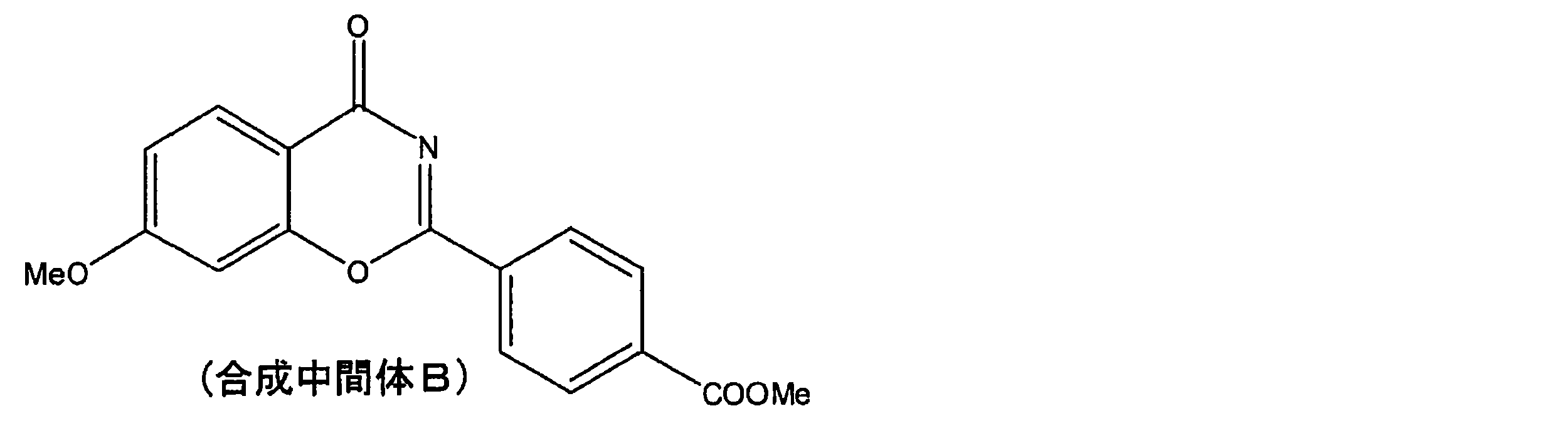
ベンズアミジン塩酸塩2.8gにメタノール100mLと28%ナトリウムメトキシドメタノール溶液3.4gを添加した。この溶液に合成中間体B5.0gを添加し、60℃で3時間攪拌した。この反応液を室温まで冷却した後、塩酸を0.2mL添加した。得られた固体を濾過、水とメタノールで洗浄して例示化合物(1)を6.1g得た(収率92%)。
MS:m/z 414(M+)1H NMR(CDCl3):δ6.55-6.56(1H),δ6.62-6.64(1H),δ7.58-7.65(3H),δ8.22-8.24(2H),δ8.62-8.65(3H),δ8.71(2H),δ13.39(1H)λmax(極大吸収波長)=341nm(EtOAc)
MS:m/z 414(M+)1H NMR(CDCl3):δ6.55-6.56(1H),δ6.62-6.64(1H),δ7.58-7.65(3H),δ8.22-8.24(2H),δ8.62-8.65(3H),δ8.71(2H),δ13.39(1H)λmax(極大吸収波長)=341nm(EtOAc)
(例示化合物(2)の合成)
4-メトキシサリチルアミド20.0gにアセトニトリル80mLとDBU36.4gを添加し溶解させた。この溶液に4-シアノベンゾイル クロリド19.8gを添加し、室温で24時間攪拌した。この反応液に水100mLと35%塩酸20mLを添加し、得られた固体を濾過、水洗浄して合成中間体Cを31.2g得た(収率88%)。
4-メトキシサリチルアミド20.0gにアセトニトリル80mLとDBU36.4gを添加し溶解させた。この溶液に4-シアノベンゾイル クロリド19.8gを添加し、室温で24時間攪拌した。この反応液に水100mLと35%塩酸20mLを添加し、得られた固体を濾過、水洗浄して合成中間体Cを31.2g得た(収率88%)。
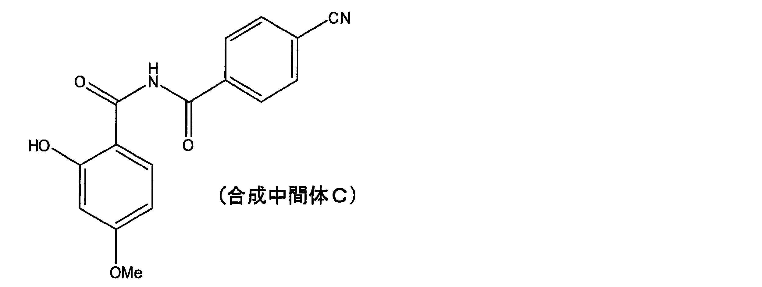
合成中間体C20.0gにアセトニトリル200mLと硫酸9.9gを添加し、90℃で4時間攪拌した。この反応液にトリエチルアミン80mLを添加し、室温まで冷却した。得られた固体を濾過、水洗浄して合成中間体Dを16.5g得た(収率88%)。

ベンズアミジン塩酸塩3.1gにメタノール100mLと28%ナトリウムメトキシドメタノール溶液3.8gを添加した。この溶液に合成中間体D5.0gを添加し、60℃で3時間攪拌した。この反応液を室温まで冷却した後、35%塩酸を0.2mL添加した。得られた固体を濾過、水とメタノールで洗浄して例示化合物(2)を6.3g得た(収率93%)。
MS:m/z 381(M+)1H NMR(CDCl3):δ6.55-6.56(1H),δ6.62-6.64(1H),δ7.58-7.62(3H),δ7.65-7.69(2H),δ8.60-8.62(3H),δ8.76(2H),δ13.26(1H)λmax=342nm(EtOAc)
MS:m/z 381(M+)1H NMR(CDCl3):δ6.55-6.56(1H),δ6.62-6.64(1H),δ7.58-7.62(3H),δ7.65-7.69(2H),δ8.60-8.62(3H),δ8.76(2H),δ13.26(1H)λmax=342nm(EtOAc)
(例示化合物(3)の合成)
4-メトキシサリチルアミド20.0gにアセトニトリル80mLとDBU36.4gを添加し溶解させた。この溶液に4-(トリフルオロメチル)ベンゾイルクロリド24.9gを添加し、室温で24時間攪拌した。この反応液に水100mLと35%塩酸20mLを添加し、得られた固体を濾過、水洗浄して合成中間体Eを37.5g得た(収率92%)。
4-メトキシサリチルアミド20.0gにアセトニトリル80mLとDBU36.4gを添加し溶解させた。この溶液に4-(トリフルオロメチル)ベンゾイルクロリド24.9gを添加し、室温で24時間攪拌した。この反応液に水100mLと35%塩酸20mLを添加し、得られた固体を濾過、水洗浄して合成中間体Eを37.5g得た(収率92%)。
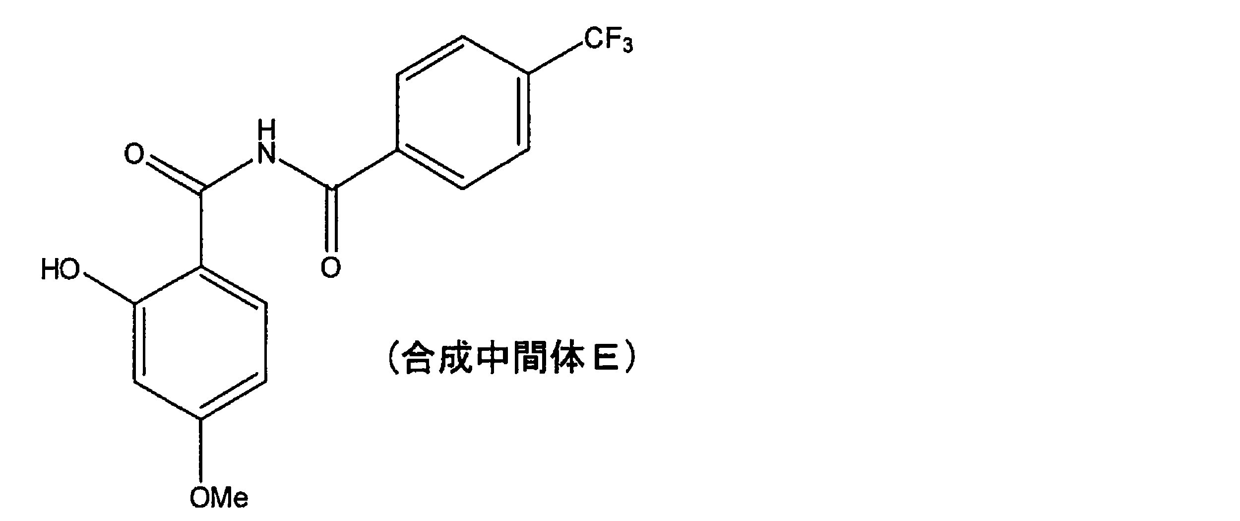
合成中間体E20.0gにアセトニトリル200mLと硫酸8.8gを添加し、90℃で4時間攪拌した。この反応液にトリエチルアミン80mLを添加し、室温まで冷却した。得られた固体を濾過、水洗浄して合成中間体Fを17.0g得た(収率90%)。

ベンズアミジン塩酸塩2.8gにメタノール100mLと28%ナトリウムメトキシドメタノール溶液3.3gを添加した。この溶液に合成中間体F5.0gを添加し、60℃で3時間攪拌した。この反応液を室温まで冷却した後、35%塩酸を0.2mL添加した。得られた固体を濾過、水とメタノールで洗浄して例示化合物(3)を6.0g得た(収率92%)。
MS:m/z 424(M+)1H NMR(CDCl3):δ6.56-6.57(1H),δ6.62-6.65(1H),δ7.58-7.66(3H),δ7.82-7.85(2H),δ8.62-8.64(3H),δ8.76(2H),δ13.35(1H)λmax=342nm(EtOAc)
MS:m/z 424(M+)1H NMR(CDCl3):δ6.56-6.57(1H),δ6.62-6.65(1H),δ7.58-7.66(3H),δ7.82-7.85(2H),δ8.62-8.64(3H),δ8.76(2H),δ13.35(1H)λmax=342nm(EtOAc)
(例示化合物(4)の合成)
4-メトキシサリチルアミド20.0gにアセトニトリル80mLとDBU36.4gを添加し溶解させた。この溶液に4-クロロベンゾイルクロリド20.9gを添加し、室温で24時間攪拌した。この反応液に水100mLと塩酸20mLを添加し、得られた固体を濾過、水洗浄して合成中間体Gを35.0g得た(収率96%)。
4-メトキシサリチルアミド20.0gにアセトニトリル80mLとDBU36.4gを添加し溶解させた。この溶液に4-クロロベンゾイルクロリド20.9gを添加し、室温で24時間攪拌した。この反応液に水100mLと塩酸20mLを添加し、得られた固体を濾過、水洗浄して合成中間体Gを35.0g得た(収率96%)。
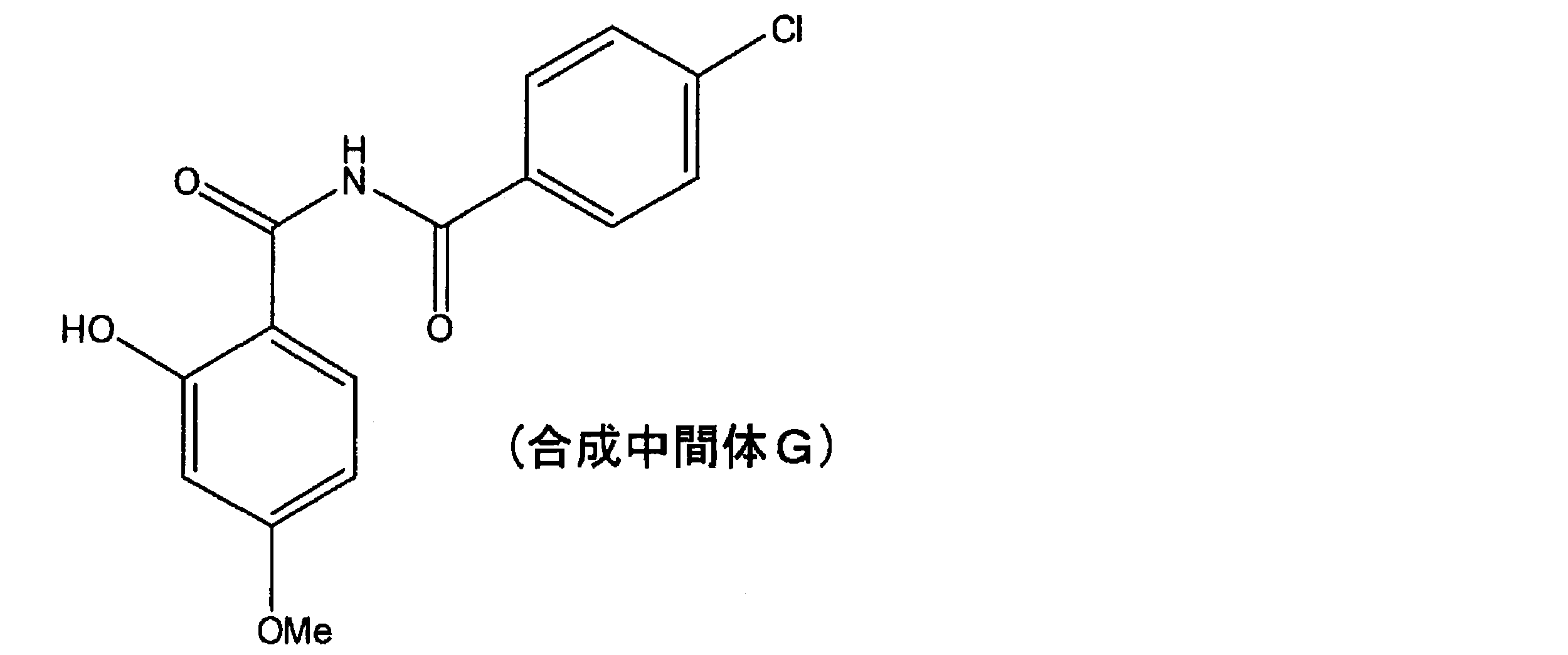
合成中間体G20.0gにアセトニトリル200mLと硫酸9.6gを添加し、90℃で4時間攪拌した。この反応液にトリエチルアミン80mLを添加し、室温まで冷却した。得られた固体を濾過、水洗浄して合成中間体Hを17.1g得た(収率91%)。

ベンズアミジン塩酸塩3.0gにメタノール100mLと28%ナトリウムメトキシドメタノール溶液3.7gを添加した。この溶液に合成中間体H5.0gを添加し、60℃で3時間攪拌した。この反応液を室温まで冷却した後、35%塩酸を0.2mL添加した。得られた固体を濾過、水とメタノールで洗浄して例示化合物(4)を6.5g得た(収率96%)。
MS:m/z 390(M+)1H NMR(CDCl3):δ6.54-6.55(1H),δ6.61-6.63(1H),δ7.53-7.67(5H),δ8.60-8.62(5H),δ13.26(1H)λmax=340nm(EtOAc)
MS:m/z 390(M+)1H NMR(CDCl3):δ6.54-6.55(1H),δ6.61-6.63(1H),δ7.53-7.67(5H),δ8.60-8.62(5H),δ13.26(1H)λmax=340nm(EtOAc)
(例示化合物(5)の合成)
4-メトキシサリチルアミド20.0gにアセトニトリル80mLとDBU36.4gを添加し溶解させた。この溶液にベンゾイルクロリド16.8gを添加し、室温で24時間攪拌した。この反応液に水100mLと35%塩酸20mLを添加し、得られた固体を濾過、水洗浄して合成中間体Iを29.5g得た(収率91%)。
4-メトキシサリチルアミド20.0gにアセトニトリル80mLとDBU36.4gを添加し溶解させた。この溶液にベンゾイルクロリド16.8gを添加し、室温で24時間攪拌した。この反応液に水100mLと35%塩酸20mLを添加し、得られた固体を濾過、水洗浄して合成中間体Iを29.5g得た(収率91%)。
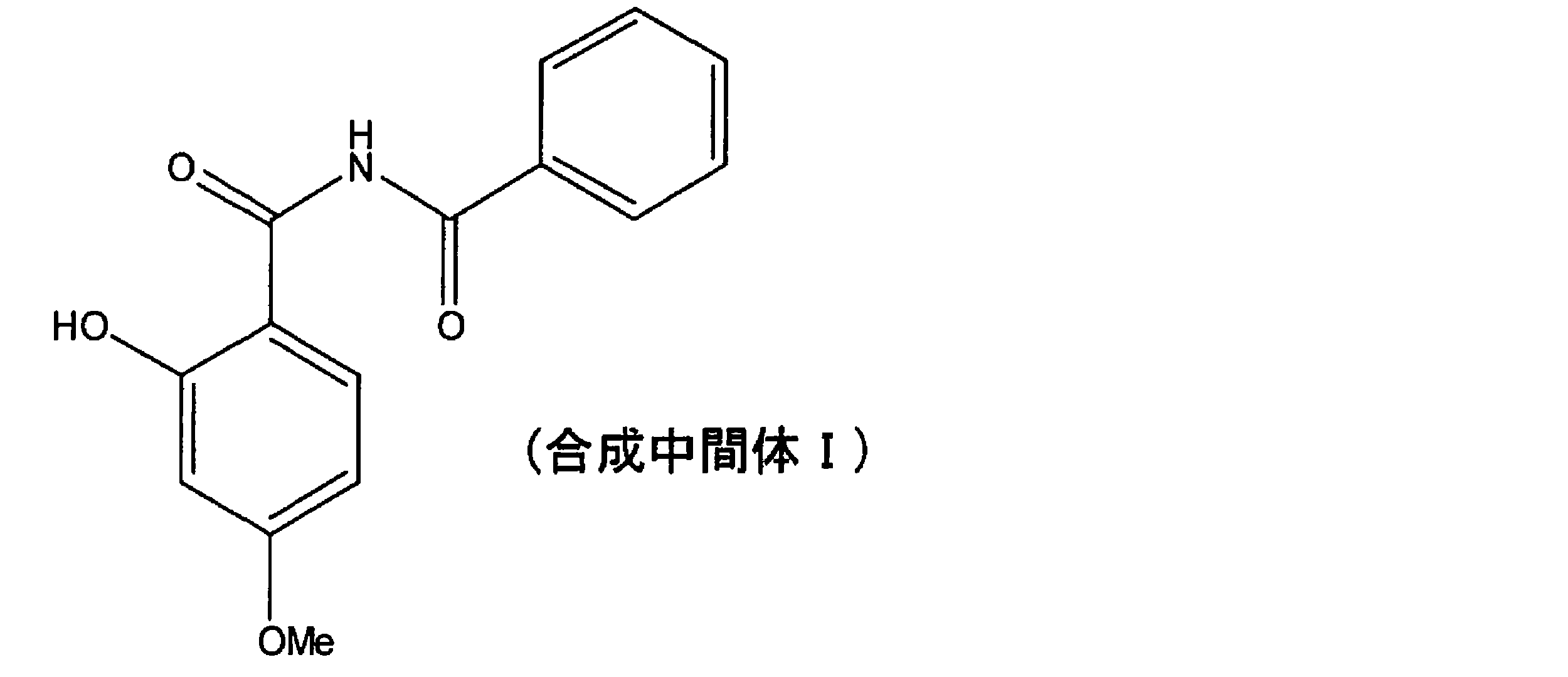
合成中間体I25.0gにアセトニトリル250mLと硫酸13.5gを添加し、90℃で4時間攪拌した。この反応液にトリエチルアミン100mLを添加し、室温まで冷却した。得られた固体を濾過、水洗浄して合成中間体Jを21.1g得た(収率91%)。

塩酸4-アミジノベンズアミド3.5gにメタノール100mLと28%ナトリウムメトキシドメタノール溶液3.4gを添加した。この溶液に合成中間体J4.0gを添加し、60℃で3時間攪拌した。この反応液を室温まで冷却した後、35%塩酸を0.2mL添加した。得られた固体を濾過、水とメタノールで洗浄して例示化合物(5)を5.8g得た(収率92%)。
MS:m/z 399(M+)1H NMR(CDCl3):δ6.57(1H),δ6.63-6.65(1H),δ7.58-7.66(3H),δ8.00-8.02(2H),δ8.64-8.66(3H),δ8.74(2H),δ13.41(1H)λmax=340nm(EtOAc)
MS:m/z 399(M+)1H NMR(CDCl3):δ6.57(1H),δ6.63-6.65(1H),δ7.58-7.66(3H),δ8.00-8.02(2H),δ8.64-8.66(3H),δ8.74(2H),δ13.41(1H)λmax=340nm(EtOAc)
(例示化合物(29)の合成)
例示化合物(1)10gに2-エチルヘキサノール31.6g、NaOMe0.13gとキシレン100mLを添加し、減圧下90℃で6時間攪拌した。この反応液に水と酢酸エチルを添加して攪拌し、分液した有機相を濃縮した。得られた残渣をヘキサン/イソプロピルアルコール(体積比で1:10)で晶析することで例示化合物(29)を11.5g得た(収率93%)。
MS:m/z 512(M+)
例示化合物(1)10gに2-エチルヘキサノール31.6g、NaOMe0.13gとキシレン100mLを添加し、減圧下90℃で6時間攪拌した。この反応液に水と酢酸エチルを添加して攪拌し、分液した有機相を濃縮した。得られた残渣をヘキサン/イソプロピルアルコール(体積比で1:10)で晶析することで例示化合物(29)を11.5g得た(収率93%)。
MS:m/z 512(M+)
(例示化合物(32)の合成)
例示化合物(1)10gにファインオキソコール180N(日産化学化学工業製)9.8g、NaOMe0.13gとキシレン100mLを添加し、減圧下90℃で6時間攪拌した。この反応液に水と酢酸エチルを添加して攪拌し、分液した有機相を濃縮した。得られた残渣をヘキサン/イソプロピルアルコール(体積比で1:10)で晶析することで例示化合物(32)を15.1g得た(収率96%)。
MS:m/z 652(M+)λmax=340nm(EtOAc)
例示化合物(1)10gにファインオキソコール180N(日産化学化学工業製)9.8g、NaOMe0.13gとキシレン100mLを添加し、減圧下90℃で6時間攪拌した。この反応液に水と酢酸エチルを添加して攪拌し、分液した有機相を濃縮した。得られた残渣をヘキサン/イソプロピルアルコール(体積比で1:10)で晶析することで例示化合物(32)を15.1g得た(収率96%)。
MS:m/z 652(M+)λmax=340nm(EtOAc)
(例示化合物(63)の合成)
4-メトキシサリチル酸フェニル10.0gにメタノール100mL、28%ナトリウムメトキシドメタノール溶液15.8g、塩酸4-アミジノ安息香酸メチル14.6gを添加した。この溶液を60℃で5時間攪拌した。この反応液を室温まで冷却した後、35%塩酸を0.2mL添加した。得られた固体を濾過、水とメタノールで洗浄して例示化合物(63)を18.0g得た(収率93%)。
MS:m/z 472(M+)
4-メトキシサリチル酸フェニル10.0gにメタノール100mL、28%ナトリウムメトキシドメタノール溶液15.8g、塩酸4-アミジノ安息香酸メチル14.6gを添加した。この溶液を60℃で5時間攪拌した。この反応液を室温まで冷却した後、35%塩酸を0.2mL添加した。得られた固体を濾過、水とメタノールで洗浄して例示化合物(63)を18.0g得た(収率93%)。
MS:m/z 472(M+)
(例示化合物(64)の合成)
塩酸4-アミジノ安息香酸メチル4.2gにメタノール100mLと28%ナトリウムメトキシドメタノール溶液3.8gを添加した。この溶液に合成中間体D5.0gを添加し、60℃で3時間攪拌した。この反応液を室温まで冷却した後、35%塩酸を0.2mL添加した。得られた固体を濾過、水とメタノールで洗浄して例示化合物(64)を7.5g得た(収率95%)。
MS:m/z 439(M+)
塩酸4-アミジノ安息香酸メチル4.2gにメタノール100mLと28%ナトリウムメトキシドメタノール溶液3.8gを添加した。この溶液に合成中間体D5.0gを添加し、60℃で3時間攪拌した。この反応液を室温まで冷却した後、35%塩酸を0.2mL添加した。得られた固体を濾過、水とメタノールで洗浄して例示化合物(64)を7.5g得た(収率95%)。
MS:m/z 439(M+)
(例示化合物(65)の合成)
塩酸4-アミジノベンズアミド3.6gにメタノール100mLと28%ナトリウムメトキシドメタノール溶液3.4gを添加した。この溶液に合成中間体B5.0gを添加し、60℃で3時間攪拌した。この反応液を室温まで冷却した後、35%塩酸を0.2mL添加した。得られた固体を濾過、水とメタノールで洗浄して例示化合物(65)を6.9g得た(収率94%)。
MS:m/z 457(M+)
塩酸4-アミジノベンズアミド3.6gにメタノール100mLと28%ナトリウムメトキシドメタノール溶液3.4gを添加した。この溶液に合成中間体B5.0gを添加し、60℃で3時間攪拌した。この反応液を室温まで冷却した後、35%塩酸を0.2mL添加した。得られた固体を濾過、水とメタノールで洗浄して例示化合物(65)を6.9g得た(収率94%)。
MS:m/z 457(M+)
(例示化合物(75)の合成)
サリチルアミド20.0gにアセトニトリル80mLとDBU44.4gを添加し溶解させた。この溶液に4-(クロロホルミル)安息香酸メチル29.0gを添加し、室温で24時間攪拌した。この反応液に水100mLと塩酸20mLを添加し、得られた固体を濾過、水洗浄して合成中間体Kを40.0g得た(収率92%)。
サリチルアミド20.0gにアセトニトリル80mLとDBU44.4gを添加し溶解させた。この溶液に4-(クロロホルミル)安息香酸メチル29.0gを添加し、室温で24時間攪拌した。この反応液に水100mLと塩酸20mLを添加し、得られた固体を濾過、水洗浄して合成中間体Kを40.0g得た(収率92%)。

合成中間体K20.0gにアセトニトリル200mLと硫酸9.4gを添加し、90℃で4時間攪拌した。この反応液にトリエチルアミン80mLを添加し、室温まで冷却した。得られた固体を濾過、水洗浄して合成中間体Lを18.2g得た(収率97%)。

ベンズアミジン塩酸塩3.1gにメタノール100mLと28%ナトリウムメトキシドメタノール溶液3.8gを添加した。この溶液に合成中間体L5.0gを添加し、60℃で3時間攪拌した。この反応液を室温まで冷却した後、35%塩酸を0.2mL添加した。得られた固体を濾過、水とメタノールで洗浄して例示化合物(75)を6.4g得た(収率94%)。
MS:m/z 384(M+)
MS:m/z 384(M+)
(例示化合物(80)の合成)
2-ヒドロキシ-4-メチルベンズアミド20.0gにアセトニトリル80mLとDBU40.3gを添加し溶解させた。この溶液に4-(クロロホルミル)安息香酸メチル25.8gを添加し、室温で24時間攪拌した。この反応液に水100mLと35%塩酸20mLを添加し、得られた固体を濾過、水洗浄して合成中間体Mを36.3g得た(収率89%)。
2-ヒドロキシ-4-メチルベンズアミド20.0gにアセトニトリル80mLとDBU40.3gを添加し溶解させた。この溶液に4-(クロロホルミル)安息香酸メチル25.8gを添加し、室温で24時間攪拌した。この反応液に水100mLと35%塩酸20mLを添加し、得られた固体を濾過、水洗浄して合成中間体Mを36.3g得た(収率89%)。

合成中間体M20.0gにアセトニトリル200mLと硫酸9.1gを添加し、90℃で4時間攪拌した。この反応液にトリエチルアミン80mLを添加し、室温まで冷却した。得られた固体を濾過、水洗浄して合成中間体Nを17.6g得た(収率93%)。
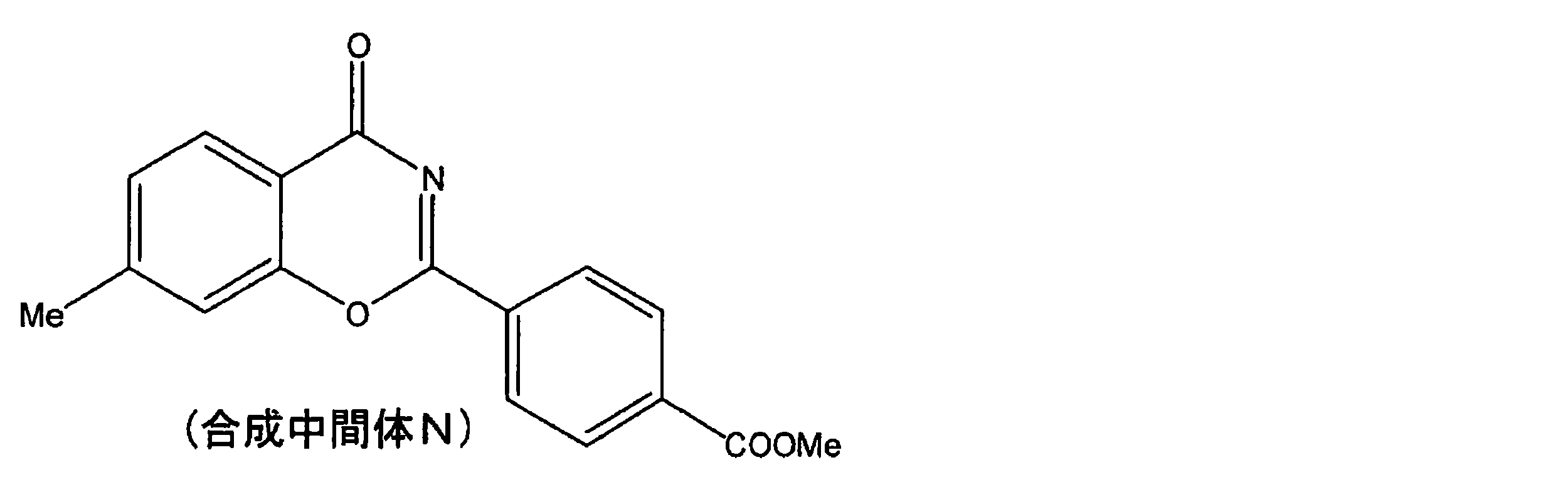
ベンズアミジン塩酸塩2.9gにメタノール100mLと28%ナトリウムメトキシドメタノール溶液3.7gを添加した。この溶液に合成中間体N5.0gを添加し、60℃で3時間攪拌した。この反応液を室温まで冷却した後、35%塩酸を0.2mL添加した。得られた固体を濾過、水とメタノールで洗浄して例示化合物(80)を6.3g得た(収率94%)。
MS:m/z 398(M+)
MS:m/z 398(M+)
(例示化合物(81)の合成)
2-ヒドロキシ-4-(トリフルオロメチル)ベンズアミド20.0gにアセトニトリル80mLとDBU29.7gを添加し溶解させた。この溶液に4-(クロロホルミル)安息香酸メチル19.4gを添加し、室温で24時間攪拌した。この反応液に水100mLと35%塩酸20mLを添加し、得られた固体を濾過、水洗浄して合成中間体Oを34.1g得た(収率95%)。
2-ヒドロキシ-4-(トリフルオロメチル)ベンズアミド20.0gにアセトニトリル80mLとDBU29.7gを添加し溶解させた。この溶液に4-(クロロホルミル)安息香酸メチル19.4gを添加し、室温で24時間攪拌した。この反応液に水100mLと35%塩酸20mLを添加し、得られた固体を濾過、水洗浄して合成中間体Oを34.1g得た(収率95%)。
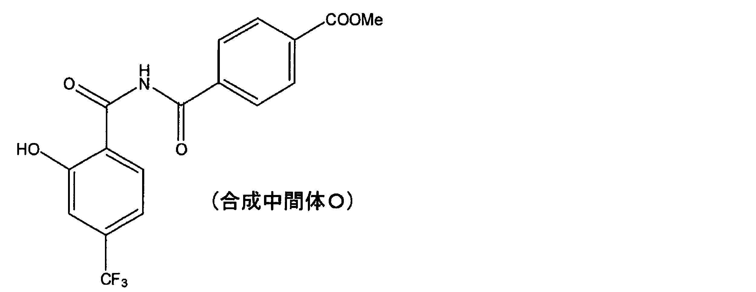
合成中間体O20.0gにアセトニトリル200mLと硫酸6.9gを添加し、90℃で4時間攪拌した。この反応液にトリエチルアミン80mLを添加し、室温まで冷却した。得られた固体を濾過、水洗浄して合成中間体Pを18.4g得た(収率97%)。
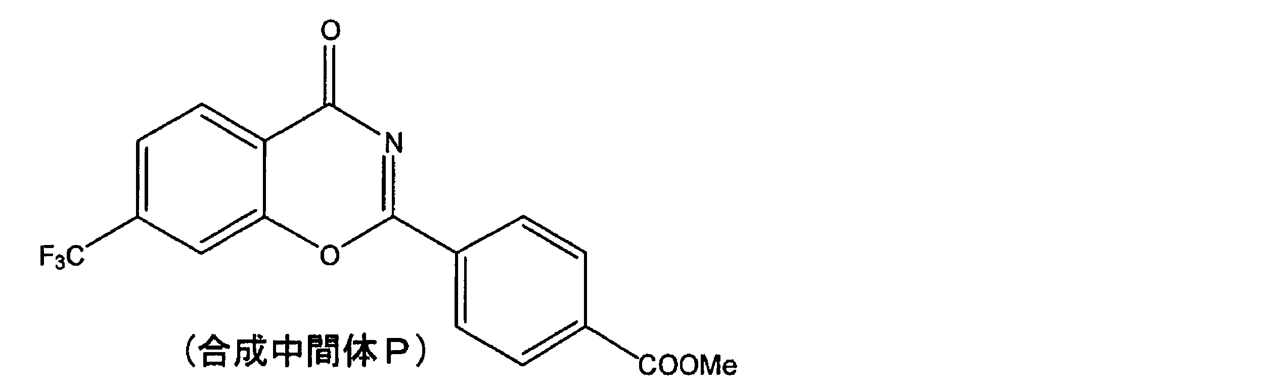
ベンズアミジン塩酸塩2.3gにメタノール100mLと28%ナトリウムメトキシドメタノール溶液3.4gを添加した。この溶液に合成中間体P5.0gを添加し、60℃で3時間攪拌した。この反応液を室温まで冷却した後、35%塩酸を0.2mL添加した。得られた固体を濾過、水とメタノールで洗浄して例示化合物(81)を5.9g得た(収率91%)。
MS:m/z 452(M+)
MS:m/z 452(M+)
(例示化合物(90)の合成)
2-ヒドロキシ-5-メトキシベンズアミド20.0gにアセトニトリル80mLとDBU36.4gを添加し溶解させた。この溶液に4-(クロロホルミル)安息香酸メチル23.8gを添加し、室温で24時間攪拌した。この反応液に水100mLと35%塩酸20mLを添加し、得られた固体を濾過、水洗浄して合成中間体Qを38.0g得た(収率96%)。
2-ヒドロキシ-5-メトキシベンズアミド20.0gにアセトニトリル80mLとDBU36.4gを添加し溶解させた。この溶液に4-(クロロホルミル)安息香酸メチル23.8gを添加し、室温で24時間攪拌した。この反応液に水100mLと35%塩酸20mLを添加し、得られた固体を濾過、水洗浄して合成中間体Qを38.0g得た(収率96%)。

合成中間体Q20.0gにアセトニトリル200mLと硫酸8.9gを添加し、90℃で4時間攪拌した。この反応液にトリエチルアミン80mLを添加し、室温まで冷却した。得られた固体を濾過、水洗浄して合成中間体Rを18.1g得た(収率96%)。

ベンズアミジン塩酸塩2.8gにメタノール100mLと28%ナトリウムメトキシドメタノール溶液3.4gを添加した。この溶液に合成中間体R5.0gを添加し、60℃で3時間攪拌した。この反応液を室温まで冷却した後、35%塩酸を0.2mL添加した。得られた固体を濾過、水とメタノールで洗浄して例示化合物(90)を6.2g得た(収率93%)。
MS:m/z 414(M+)
MS:m/z 414(M+)
(例示化合物(93)の合成)
2-ヒドロキシ-5-クロロベンズアミド20.0gにアセトニトリル80mLとDBU35.4gを添加し溶解させた。この溶液に4-(クロロホルミル)安息香酸メチル23.1gを添加し、室温で24時間攪拌した。この反応液に水100mLと35%塩酸20mLを添加し、得られた固体を濾過、水洗浄して合成中間体Sを38.1g得た(収率98%)。
2-ヒドロキシ-5-クロロベンズアミド20.0gにアセトニトリル80mLとDBU35.4gを添加し溶解させた。この溶液に4-(クロロホルミル)安息香酸メチル23.1gを添加し、室温で24時間攪拌した。この反応液に水100mLと35%塩酸20mLを添加し、得られた固体を濾過、水洗浄して合成中間体Sを38.1g得た(収率98%)。
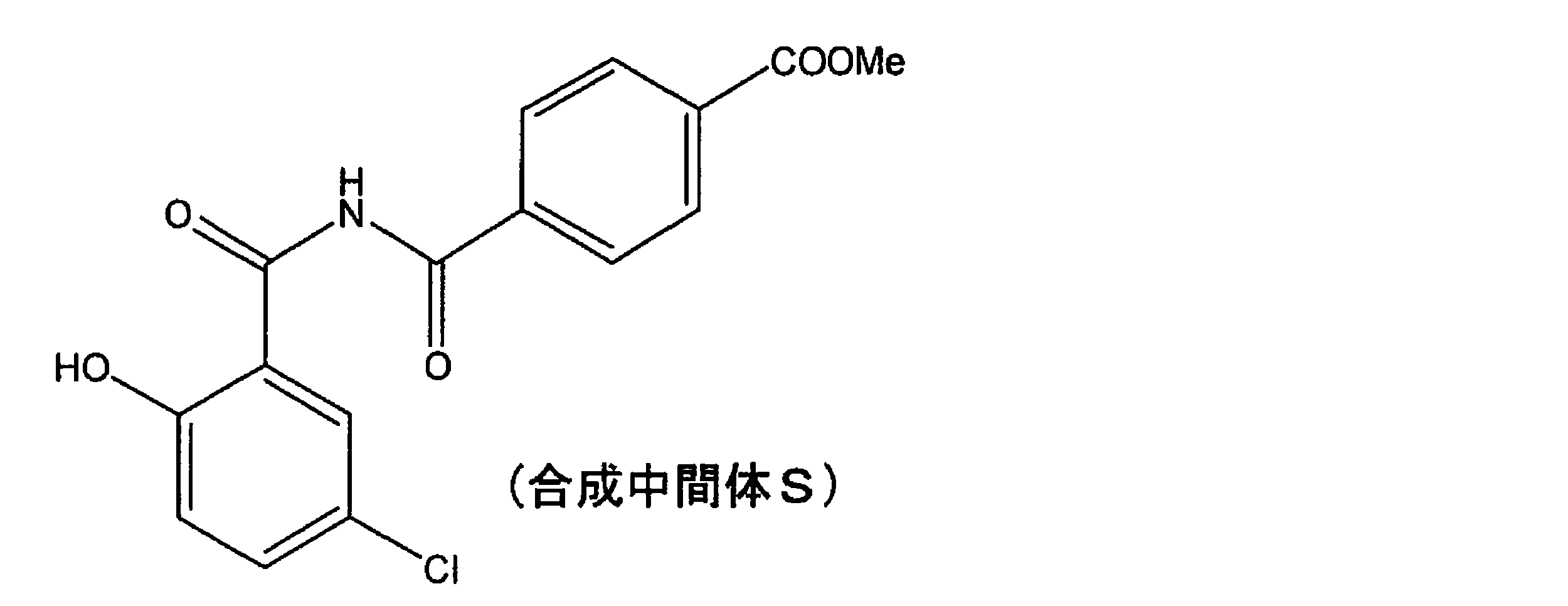
合成中間体S20.0gにアセトニトリル200mLと硫酸9.0gを添加し、90℃で4時間攪拌した。この反応液にトリエチルアミン80mLを添加し、室温まで冷却した。得られた固体を濾過、水洗浄して合成中間体Tを18.3g得た(収率97%)。

ベンズアミジン塩酸塩2.5gにメタノール100mLと28%ナトリウムメトキシドメタノール溶液3.3gを添加した。この溶液に合成中間体T5.0gを添加し、60℃で3時間攪拌した。この反応液を室温まで冷却した後、35%塩酸を0.2mL添加した。得られた固体を濾過、水とメタノールで洗浄して例示化合物(93)を6.1g得た(収率92%)。
MS:m/z 418(M+)
MS:m/z 418(M+)
(例示化合物(96)の合成)
2-ヒドロキシ-3-メトキシベンズアミド20.0gにアセトニトリル80mLとDBU36.4gを添加し溶解させた。この溶液に4-(クロロホルミル)安息香酸メチル23.8gを添加し、室温で24時間攪拌した。この反応液に水100mLと35%塩酸20mLを添加し、得られた固体を濾過、水洗浄して合成中間体Uを37.8g得た(収率95%)。
2-ヒドロキシ-3-メトキシベンズアミド20.0gにアセトニトリル80mLとDBU36.4gを添加し溶解させた。この溶液に4-(クロロホルミル)安息香酸メチル23.8gを添加し、室温で24時間攪拌した。この反応液に水100mLと35%塩酸20mLを添加し、得られた固体を濾過、水洗浄して合成中間体Uを37.8g得た(収率95%)。

合成中間体U20.0gにアセトニトリル200mLと硫酸8.9gを添加し、90℃で4時間攪拌した。この反応液にトリエチルアミン80mLを添加し、室温まで冷却した。得られた固体を濾過、水洗浄して合成中間体Vを17.7g得た(収率94%)。
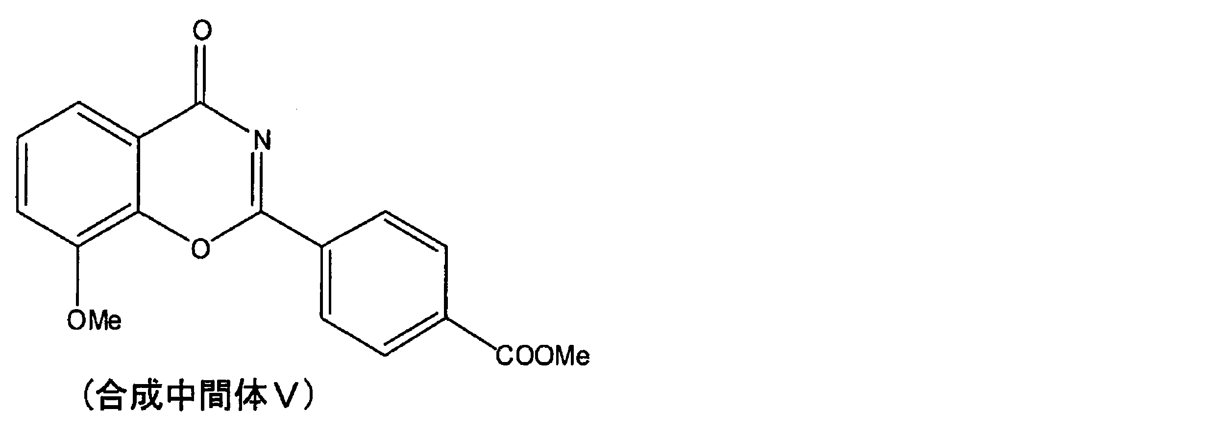
ベンズアミジン塩酸塩2.8gにメタノール100mLと28%ナトリウムメトキシドメタノール溶液3.4gを添加した。この溶液に合成中間体V5.0gを添加し、60℃で3時間攪拌した。この反応液を室温まで冷却した後、35%塩酸を0.2mL添加した。得られた固体を濾過、水とメタノールで洗浄して例示化合物(96)を6.5g得た(収率98%)。
MS:m/z 414(M+)
MS:m/z 414(M+)
(例示化合物(107)の合成)
3-ヒドロキシ-2-ナフトアミド20.0gにアセトニトリル80mLとDBU32.4gを添加し溶解させた。この溶液に4-(クロロホルミル)安息香酸メチル21.2gを添加し、室温で24時間攪拌した。この反応液に水100mLと35%塩酸20mLを添加し、得られた固体を濾過、水洗浄して合成中間体Wを35.1g得た(収率94%)。
3-ヒドロキシ-2-ナフトアミド20.0gにアセトニトリル80mLとDBU32.4gを添加し溶解させた。この溶液に4-(クロロホルミル)安息香酸メチル21.2gを添加し、室温で24時間攪拌した。この反応液に水100mLと35%塩酸20mLを添加し、得られた固体を濾過、水洗浄して合成中間体Wを35.1g得た(収率94%)。
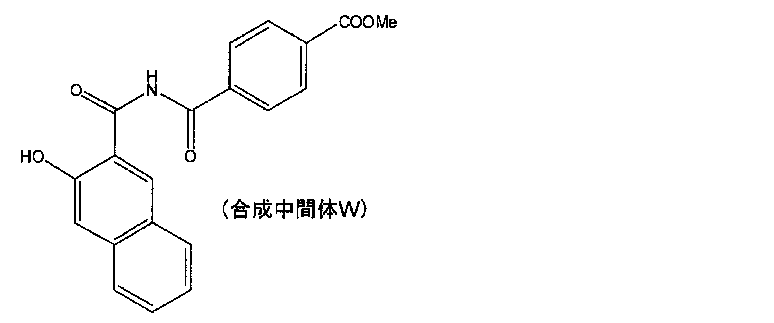
合成中間体W20.0gにアセトニトリル200mLと硫酸9.1gを添加し、90℃で4時間攪拌した。この反応液にトリエチルアミン80mLを添加し、室温まで冷却した。得られた固体を濾過、水洗浄して合成中間体Xを17.9g得た(収率94%)。

ベンズアミジン塩酸塩2.3gにメタノール100mLと28%ナトリウムメトキシドメタノール溶液3.0gを添加した。この溶液に合成中間体X5.0gを添加し、60℃で3時間攪拌した。この反応液を室温まで冷却した後、35%塩酸を0.2mL添加した。得られた固体を濾過、水とメタノールで洗浄して例示化合物(107)を6.1g得た(収率94%)。
MS:m/z 434(M+)
MS:m/z 434(M+)
(例示化合物(17)の合成)
4-メトキシサリチルアミド20.0gにアセトニトリル80mLとDBU36.4gを添加し溶解させた。この溶液に3-シアノベンゾイル クロリド19.8gを添加し、室温で24時間攪拌した。この反応液に水100mLと35%塩酸20mLを添加し、得られた固体を濾過、水洗浄して合成中間体Yを34.5g得た(収率97%)。
4-メトキシサリチルアミド20.0gにアセトニトリル80mLとDBU36.4gを添加し溶解させた。この溶液に3-シアノベンゾイル クロリド19.8gを添加し、室温で24時間攪拌した。この反応液に水100mLと35%塩酸20mLを添加し、得られた固体を濾過、水洗浄して合成中間体Yを34.5g得た(収率97%)。
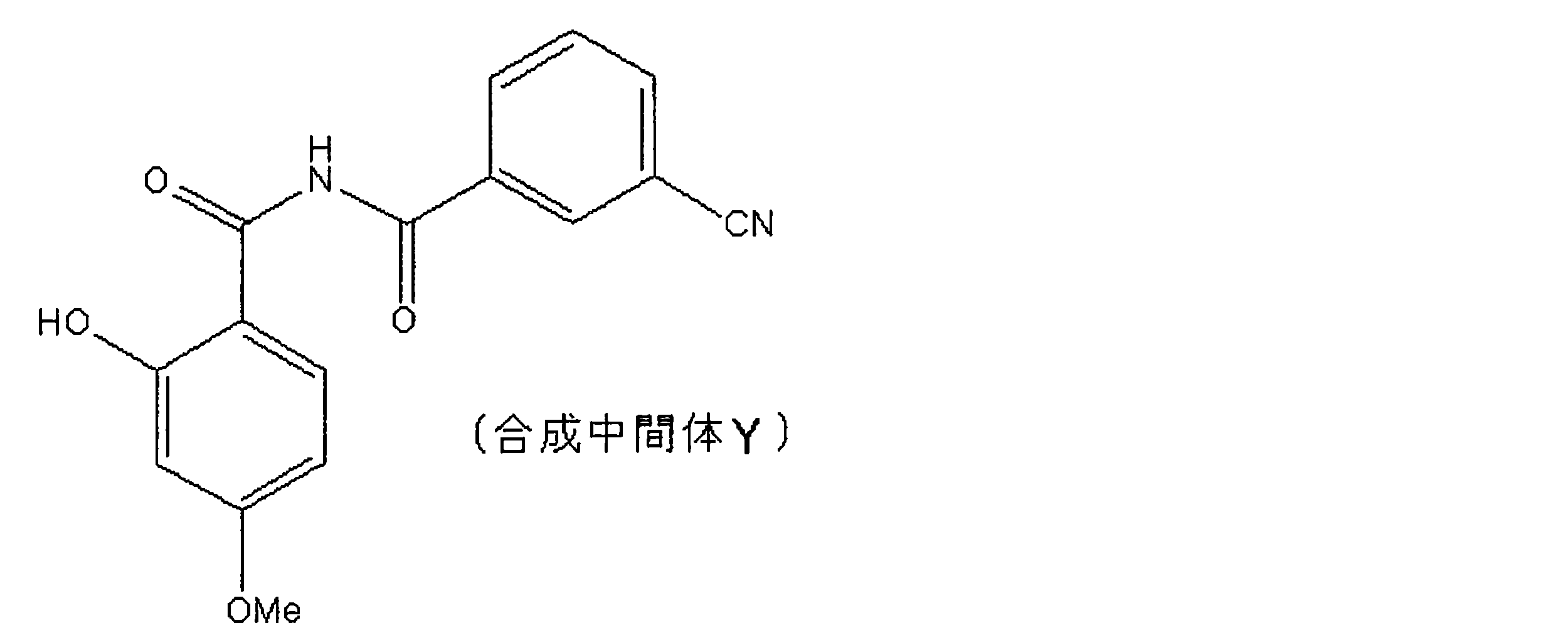
合成中間体Y20.0gにアセトニトリル200mLと硫酸9.9gを添加し、90℃で4時間攪拌した。この反応液にトリエチルアミン80mLを添加し、室温まで冷却した。得られた固体を濾過、水洗浄して合成中間体Zを16.7g得た(収率89%)。
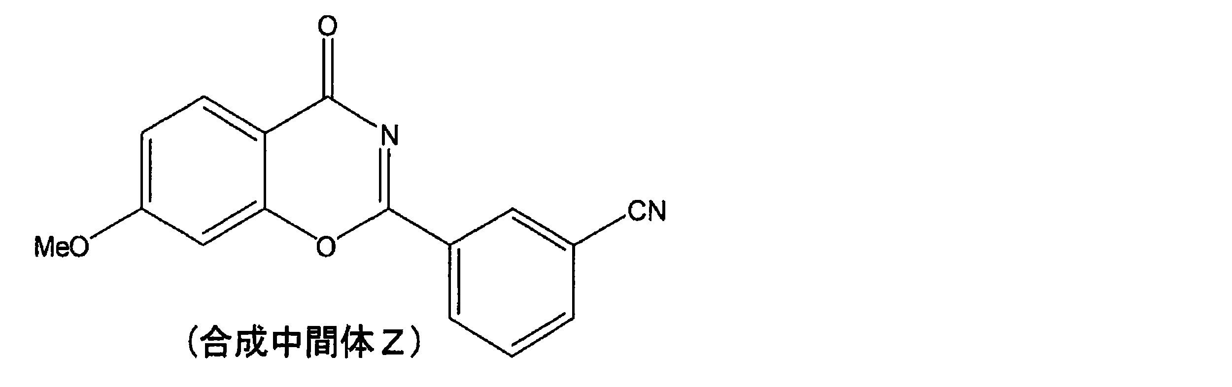
ベンズアミジン塩酸塩3.1gにメタノール100mLと28%ナトリウムメトキシドメタノール溶液3.8gを添加した。この溶液に合成中間体Z5.0gを添加し、60℃で3時間攪拌した。この反応液を室温まで冷却した後、35%塩酸を0.2mL添加した。得られた固体を濾過、水とメタノールで洗浄して例示化合物(17)を6.5g得た(収率96%)。
MS:m/z 381(M+)λmax=343nm(EtOAc)
MS:m/z 381(M+)λmax=343nm(EtOAc)
合成例
(例示化合物(m-2)の調製)
サリチル酸300gをトルエン600mLに懸濁させ、塩化チオニル258gとDMF7mLを加え、50℃で2時間攪拌した(溶液A)。サリチルアミド299.0gにアセトニトリル900mLとDBU(ジアザビシクロウンデセン(1,8-diazabicyclo[5.4.0]undec-7-ene))660gを添加し溶解させた溶液に、調製した溶液Aを5℃条件下で滴下し、その後、室温下で24時間攪拌した。この反応液に35%塩酸300mLを添加し、室温で2時間攪拌した。得られた固体を濾過、水洗浄して合成中間体Aを504g得た(収率90%)。
(例示化合物(m-2)の調製)
サリチル酸300gをトルエン600mLに懸濁させ、塩化チオニル258gとDMF7mLを加え、50℃で2時間攪拌した(溶液A)。サリチルアミド299.0gにアセトニトリル900mLとDBU(ジアザビシクロウンデセン(1,8-diazabicyclo[5.4.0]undec-7-ene))660gを添加し溶解させた溶液に、調製した溶液Aを5℃条件下で滴下し、その後、室温下で24時間攪拌した。この反応液に35%塩酸300mLを添加し、室温で2時間攪拌した。得られた固体を濾過、水洗浄して合成中間体Aを504g得た(収率90%)。
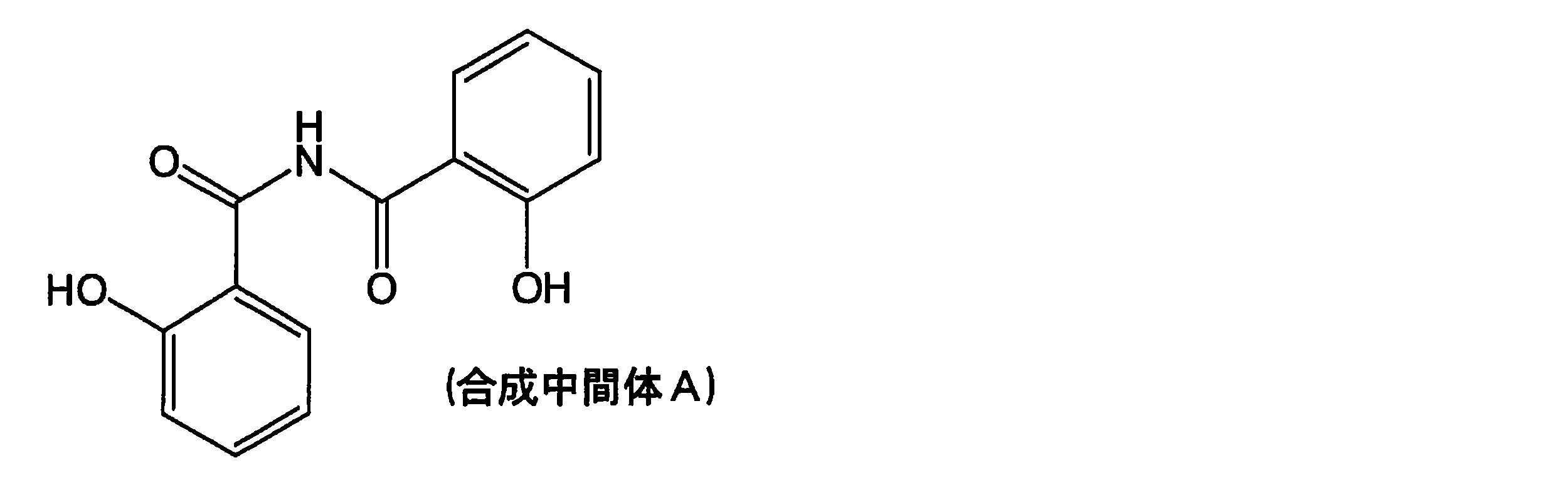
合成中間体A140gにトルエン1400mLとp-トルエンスルホン酸一水和物10.5gを添加し、150℃で6時間攪拌した。60℃まで冷却後、この反応液にトリエチルアミン14mLを添加し、室温まで冷却した。得られた固体を濾過、水洗浄して合成中間体Bを122g得た(収率94%)。

イソフタロニトリル401gにメタノール8000mLと28%ナトリウムメトキシドメタノール溶液309gを加え、室温で3時間攪拌した。この反応液に塩化アンモニウム428gを加え、室温で24時間攪拌した。この反応液をロータリーエバポレータで濃縮し、得られた固体をメタノールと酢酸エチルで洗浄して、水で再結晶することにより合成中間体Cを310g得た(収率55%)。

合成中間体C42gにメタノール1000mLと28%ナトリウムメトキシドメタノール溶液44gを加えた。この懸濁液に室温下で合成中間体Bを50g添加し、室温で2時間、60℃で2時間攪拌した。この反応液に35%塩酸2mLを加え、得られた固体をメタノールと水で洗浄することにより例示化合物(m-2)を74g得た(収率96%)。MS:m/z 367(M+)
λmax=355nm(EtOAc)
λmax=355nm(EtOAc)
(例示化合物(m-1)の調製)
例示化合物(m-2)100gにメタノール1000mLを加え、60℃で塩化水素ガスを24時間バブリングしながら攪拌した。室温まで冷却後、得られた固体をメタノールと水で洗浄することにより例示化合物(m-1)を99g得た(収率91%)。MS:m/z 400(M+)
λmax=354nm(EtOAc)
例示化合物(m-2)100gにメタノール1000mLを加え、60℃で塩化水素ガスを24時間バブリングしながら攪拌した。室温まで冷却後、得られた固体をメタノールと水で洗浄することにより例示化合物(m-1)を99g得た(収率91%)。MS:m/z 400(M+)
λmax=354nm(EtOAc)
(例示化合物(m-3)の調製)
サリチルアミド200.0gにアセトニトリル800mLとDBU444.0gを添加し溶解させた。この溶液に3-(トリフルオロメチル)ベンゾイルクロリド303.9gを添加し、室温で24時間攪拌した。この反応液に水2000mLと塩酸200mLを添加し、得られた固体を濾過、水洗浄して合成中間体Dを428.3g得た(収率95%)。
サリチルアミド200.0gにアセトニトリル800mLとDBU444.0gを添加し溶解させた。この溶液に3-(トリフルオロメチル)ベンゾイルクロリド303.9gを添加し、室温で24時間攪拌した。この反応液に水2000mLと塩酸200mLを添加し、得られた固体を濾過、水洗浄して合成中間体Dを428.3g得た(収率95%)。
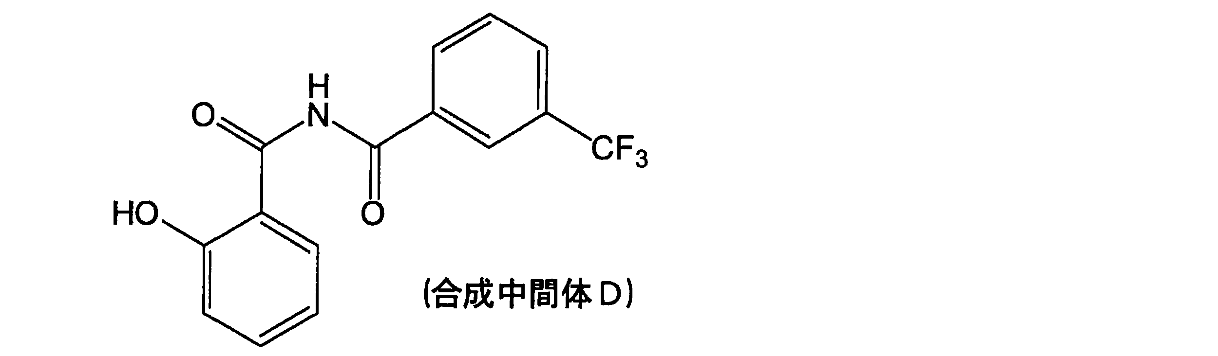
合成中間体D34.0gにアセトニトリル240mLと硫酸20.2gを添加し、90℃で4時間攪拌した。この反応液にトリエチルアミン150mLを添加し、室温まで冷却した。得られた固体を濾過、水洗浄して合成中間体Eを34.8g得た(収率94%)。


(X-2の合成)
3つ口フラスコに、アセトキシム39.5g(1.1モル当量)、DMF(N,N-ジメチルホルムアミド)600mL、カリウム-t-ブトキシド60.6g(1.1モル当量)を入れて室温で30分攪拌した。その後、内温を0℃とし、そこへ化合物(X-1)60g(1.0モル当量)をゆっくり滴下した。滴下後、内温を25℃まで昇温し、その温度で1時間攪拌した。
反応混合物を塩化アンモニウム水溶液と酢酸エチルで抽出・分液操作を行い、得られた有機相に飽和食塩水を加えて洗浄し分液した。こうして得られた有機相を、ロータリーエバポレータで濃縮して得られた残留物を化合物(X-2)の粗生成物として得た。
3つ口フラスコに、アセトキシム39.5g(1.1モル当量)、DMF(N,N-ジメチルホルムアミド)600mL、カリウム-t-ブトキシド60.6g(1.1モル当量)を入れて室温で30分攪拌した。その後、内温を0℃とし、そこへ化合物(X-1)60g(1.0モル当量)をゆっくり滴下した。滴下後、内温を25℃まで昇温し、その温度で1時間攪拌した。
反応混合物を塩化アンモニウム水溶液と酢酸エチルで抽出・分液操作を行い、得られた有機相に飽和食塩水を加えて洗浄し分液した。こうして得られた有機相を、ロータリーエバポレータで濃縮して得られた残留物を化合物(X-2)の粗生成物として得た。
(X-3の合成)
3つ口フラスコに、上記で得られた化合物(X-2)の組成生物を全量を入れ、エタノール700mLと1Mの塩酸水500mLを加えて、反応混合物を内温80℃まで昇温しその温度で3時間攪拌した。
反応混合物を内温25℃まで冷却し、飽和炭酸水素ナトリウム水溶液と酢酸エチルで抽出・分液操作を行い、得られた有機相に飽和食塩水を加えて洗浄し分液した。こうして得られた有機相を、ロータリーエバポレータで濃縮して得られた残留物を化合物(X-3)の粗生成物として得た。
3つ口フラスコに、上記で得られた化合物(X-2)の組成生物を全量を入れ、エタノール700mLと1Mの塩酸水500mLを加えて、反応混合物を内温80℃まで昇温しその温度で3時間攪拌した。
反応混合物を内温25℃まで冷却し、飽和炭酸水素ナトリウム水溶液と酢酸エチルで抽出・分液操作を行い、得られた有機相に飽和食塩水を加えて洗浄し分液した。こうして得られた有機相を、ロータリーエバポレータで濃縮して得られた残留物を化合物(X-3)の粗生成物として得た。
(X-4の合成)
3つ口フラスコに、フラスコ内を窒素ガスで満たした後に10%Pd-C(和光純薬工業社製)を6.5g添加し、エタノールを2,000mL、上記で得られた化合物(X-3)の組成生物を全量加えて加熱・還流した。そこへギ酸55mL(3モル当量)をゆっくり滴下し、この温度で5時間攪拌した。その後反応混合物を内温25℃まで冷却し、セライトろ過を行い炉別した母液に1,5-ナフタレンジスルホン酸を105g加えて、内温を70℃まで昇温し、30分攪拌した。その後、徐々に室温まで冷却して結晶を濾別し化合物(X-4)を100g得た。収率は化合物(X-1)を出発物質として72%であった。得られた結晶は、淡茶色であった。
1H NMR(重DMSO):δ6.95-6.98(1H)、δ7.02-7.04(1H)、δ7.40-7.51(3H)、δ7.90-7.95(1H)、δ8.75(1H)、δ8.85-8.88(2H)、δ9.03(2H)、δ10.89(1H)
3つ口フラスコに、フラスコ内を窒素ガスで満たした後に10%Pd-C(和光純薬工業社製)を6.5g添加し、エタノールを2,000mL、上記で得られた化合物(X-3)の組成生物を全量加えて加熱・還流した。そこへギ酸55mL(3モル当量)をゆっくり滴下し、この温度で5時間攪拌した。その後反応混合物を内温25℃まで冷却し、セライトろ過を行い炉別した母液に1,5-ナフタレンジスルホン酸を105g加えて、内温を70℃まで昇温し、30分攪拌した。その後、徐々に室温まで冷却して結晶を濾別し化合物(X-4)を100g得た。収率は化合物(X-1)を出発物質として72%であった。得られた結晶は、淡茶色であった。
1H NMR(重DMSO):δ6.95-6.98(1H)、δ7.02-7.04(1H)、δ7.40-7.51(3H)、δ7.90-7.95(1H)、δ8.75(1H)、δ8.85-8.88(2H)、δ9.03(2H)、δ10.89(1H)
化合物(X-4)6.8gにメタノール50mLと28%ナトリウムメトキシドメタノール溶液4.6gを添加した。この溶液に合成中間体E5.0gを添加し、60℃で3時間攪拌した。この反応液を室温まで冷却した後、35%塩酸を0.2mL添加した。得られた固体を濾過、水とメタノールで洗浄して例示化合物(m-3)を6.7g得た(収率95%)。MS:m/z 409(M+)
(例示化合物(m-10)の調製)
例示化合物(m-1)50gにエタノール2500mL、10%水酸化カリウムエタノール溶液を2000mLと水500mLを加え、室温で24時間攪拌した。35%塩酸を300mL添加し、得られた固体をメタノールと水で洗浄して例示化合物(m-10)を46g得た(収率95%)。MS:m/z 386(M+)
例示化合物(m-1)50gにエタノール2500mL、10%水酸化カリウムエタノール溶液を2000mLと水500mLを加え、室温で24時間攪拌した。35%塩酸を300mL添加し、得られた固体をメタノールと水で洗浄して例示化合物(m-10)を46g得た(収率95%)。MS:m/z 386(M+)
(例示化合物(m-18))
例示化合物(m-19)と同様の調製法で、原料の1-ヘキサノールを1-ブタノールに変更して例示化合物(m-18)を合成した。
1H NMR(CDCl3):δ1.03-1.07(3H),δ1.55-1.87(4H),δ4.41-4.45(2H),δ7.04-7.12(4H),δ7.53-7.58(2H),δ7.68-7.73(1H),δ8.34-8.36(1H),δ8.54-8.56(2H),δ8.62-8.64(1H),δ9.15(1H),δ12.93(2H)λmax=354nm(EtOAc)
例示化合物(m-19)と同様の調製法で、原料の1-ヘキサノールを1-ブタノールに変更して例示化合物(m-18)を合成した。
1H NMR(CDCl3):δ1.03-1.07(3H),δ1.55-1.87(4H),δ4.41-4.45(2H),δ7.04-7.12(4H),δ7.53-7.58(2H),δ7.68-7.73(1H),δ8.34-8.36(1H),δ8.54-8.56(2H),δ8.62-8.64(1H),δ9.15(1H),δ12.93(2H)λmax=354nm(EtOAc)
(例示化合物(m-19)の調製)
例示化合物(m-2)25gに1-ヘキサノール200gと硫酸13gを添加し、還流条件下で16時間攪拌した。室温まで冷却後、得られた固体をメタノールと水で洗浄して例示化合物(m-19)を29g得た(収率90%)。MS:m/z 470(M+)λmax=354nm(EtOAc)
例示化合物(m-2)25gに1-ヘキサノール200gと硫酸13gを添加し、還流条件下で16時間攪拌した。室温まで冷却後、得られた固体をメタノールと水で洗浄して例示化合物(m-19)を29g得た(収率90%)。MS:m/z 470(M+)λmax=354nm(EtOAc)
(例示化合物(m-20)の調製)
例示化合物(m-2)25gに2-エチルヘキサノール200gと硫酸13gを添加し、還流条件下で16時間攪拌した。室温まで冷却後、得られた固体をメタノールと水で洗浄して例示化合物(m-20)を31g得た(収率92%)。MS:m/z 498(M+)λmax=354nm(EtOAc)
例示化合物(m-2)25gに2-エチルヘキサノール200gと硫酸13gを添加し、還流条件下で16時間攪拌した。室温まで冷却後、得られた固体をメタノールと水で洗浄して例示化合物(m-20)を31g得た(収率92%)。MS:m/z 498(M+)λmax=354nm(EtOAc)
(例示化合物(m-21)の調製)
例示化合物(m-2)25gに3,5,5-トリメチル-1-ヘキサノール200gと硫酸13gを添加し、還流条件下で16時間攪拌した。室温まで冷却後、得られた固体をメタノールと水で洗浄して例示化合物(m-21)を32g得た(収率91%)。MS:m/z 512(M+)λmax=354nm(EtOAc)
例示化合物(m-2)25gに3,5,5-トリメチル-1-ヘキサノール200gと硫酸13gを添加し、還流条件下で16時間攪拌した。室温まで冷却後、得られた固体をメタノールと水で洗浄して例示化合物(m-21)を32g得た(収率91%)。MS:m/z 512(M+)λmax=354nm(EtOAc)
(例示化合物(m-25)の調製)
例示化合物(m-19)と同様の調製法で、原料の1-ヘキサノールをファインオキソコール180Nに変更して例示化合物(m-25)を合成した。
1H NMR(CDCl3):δ0.72-1.86(35H),δ4.30-4.37(2H),δ7.04-7.10(4H),δ7.51-7.55(2H),δ7.68-7.72(1H),δ8.32-8.34(1H),δ8.51-8.53(2H),δ8.61-8.63(1H),δ9.14(1H),δ12.91(2H)λmax=354nm(EtOAc)
例示化合物(m-19)と同様の調製法で、原料の1-ヘキサノールをファインオキソコール180Nに変更して例示化合物(m-25)を合成した。
1H NMR(CDCl3):δ0.72-1.86(35H),δ4.30-4.37(2H),δ7.04-7.10(4H),δ7.51-7.55(2H),δ7.68-7.72(1H),δ8.32-8.34(1H),δ8.51-8.53(2H),δ8.61-8.63(1H),δ9.14(1H),δ12.91(2H)λmax=354nm(EtOAc)
(例示化合物(m-58)の調製)
3-メトキシサリチルアミド20.0gにアセトニトリル80mLとDBU36.4gを添加し溶解させた。この溶液に3-(クロロホルミル)安息香酸メチル23.8gを添加し、室温で24時間攪拌した。この反応液に水100mLと塩酸20mLを添加し、得られた固体を濾過、水洗浄して合成中間体Hを36.0g得た(収率91%)。
3-メトキシサリチルアミド20.0gにアセトニトリル80mLとDBU36.4gを添加し溶解させた。この溶液に3-(クロロホルミル)安息香酸メチル23.8gを添加し、室温で24時間攪拌した。この反応液に水100mLと塩酸20mLを添加し、得られた固体を濾過、水洗浄して合成中間体Hを36.0g得た(収率91%)。
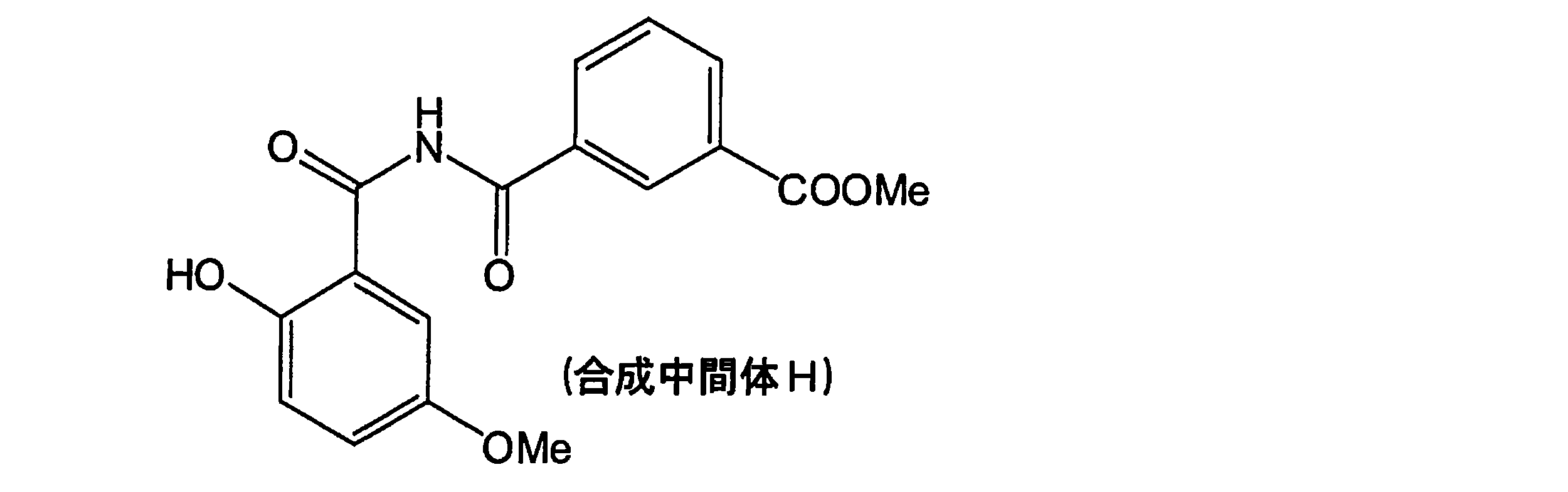
合成中間体H20.0gにアセトニトリル200mLと硫酸8.9gを添加し、90℃で4時間攪拌した。この反応液にトリエチルアミン80mLを添加し、室温まで冷却した。得られた固体を濾過、水洗浄して合成中間体Iを17.1g得た(収率90%)。

化合物(X-4)5.5gにメタノール50mLと28%ナトリウムメトキシドメタノール溶液3.4gを添加した。この溶液に合成中間体I5.0gを添加し、60℃で3時間攪拌した。この反応液を室温まで冷却した後、塩酸を0.2mL添加した。得られた固体を濾過、水とメタノールで洗浄して例示化合物(m-58)を6.3g得た(収率91%)。MS:m/z 430(M+)
(例示化合物(m-71)の調製)
例示化合物(m-3)と同様の調製法で、原料のサリチルアミドを4-メトキシサリチルアミドに変更して例示化合物(m-71)を合成した。
1H NMR(CDCl3):δ3.92(3H),δ6.58(1H),δ6.64-6.66(1H),δ7.05-7.12(2H),δ7.54-7.57(1H),δ7.74-7.79(1H),δ7.92-7.94(1H),δ8.43-8.52(2H),δ8.61-8.63(1H),δ8.73(1H),δ12.98(1H),δ13.14(1H)λmax=354nm(EtOAc)
例示化合物(m-3)と同様の調製法で、原料のサリチルアミドを4-メトキシサリチルアミドに変更して例示化合物(m-71)を合成した。
1H NMR(CDCl3):δ3.92(3H),δ6.58(1H),δ6.64-6.66(1H),δ7.05-7.12(2H),δ7.54-7.57(1H),δ7.74-7.79(1H),δ7.92-7.94(1H),δ8.43-8.52(2H),δ8.61-8.63(1H),δ8.73(1H),δ12.98(1H),δ13.14(1H)λmax=354nm(EtOAc)
(例示化合物(m-72)の調製)
例示化合物(m-3)と同様の調製法で、原料のサリチルアミドを4-メトキシサリチルアミドに変更し、3-(トリフルオロメチル)ベンゾイルクロリドを3,5-ビス(トリフルオロメチル)ベンゾイルクロリドに変更して例示化合物(m-72)を合成した。
1H NMR(CDCl3):δ3.92(3H),δ6.59(1H),δ6.66-6.68(1H),δ7.07-7.14(2H),δ7.56-7.59(1H),δ8.18(1H),δ8.40-8.42(1H),δ8.48(1H),δ8.88(2H),δ12.76(1H),δ12.94(1H)λmax=356nm(EtOAc)
例示化合物(m-3)と同様の調製法で、原料のサリチルアミドを4-メトキシサリチルアミドに変更し、3-(トリフルオロメチル)ベンゾイルクロリドを3,5-ビス(トリフルオロメチル)ベンゾイルクロリドに変更して例示化合物(m-72)を合成した。
1H NMR(CDCl3):δ3.92(3H),δ6.59(1H),δ6.66-6.68(1H),δ7.07-7.14(2H),δ7.56-7.59(1H),δ8.18(1H),δ8.40-8.42(1H),δ8.48(1H),δ8.88(2H),δ12.76(1H),δ12.94(1H)λmax=356nm(EtOAc)
(例示化合物(m-73)の調製)
例示化合物(m-19)と同様の調製法で、原料の1-ヘキサノールを3,7-ジメチル-1-オクタノールに変更して例示化合物(m-73)を合成した。
1H NMR(CDCl3):δ0.84-0.86(6H),δ1.01-1.03(3H),δ1.16-1.39(6H),δ1.49-1.74(4H),δ1.86-1.91(1H),δ4.45(2H),δ7.01-7.09(4H),δ7.51-7.55(2H),δ7.66-7.70(1H),δ8.31-8.33(1H),δ8.50-8.52(2H),δ8.59-8.61(1H),δ9.11(1H),δ12.89(2H)λmax=354nm(EtOAc)
例示化合物(m-19)と同様の調製法で、原料の1-ヘキサノールを3,7-ジメチル-1-オクタノールに変更して例示化合物(m-73)を合成した。
1H NMR(CDCl3):δ0.84-0.86(6H),δ1.01-1.03(3H),δ1.16-1.39(6H),δ1.49-1.74(4H),δ1.86-1.91(1H),δ4.45(2H),δ7.01-7.09(4H),δ7.51-7.55(2H),δ7.66-7.70(1H),δ8.31-8.33(1H),δ8.50-8.52(2H),δ8.59-8.61(1H),δ9.11(1H),δ12.89(2H)λmax=354nm(EtOAc)
また、トリアジン環構造を有する化合物として、以下の市販品の化合物を用いた。
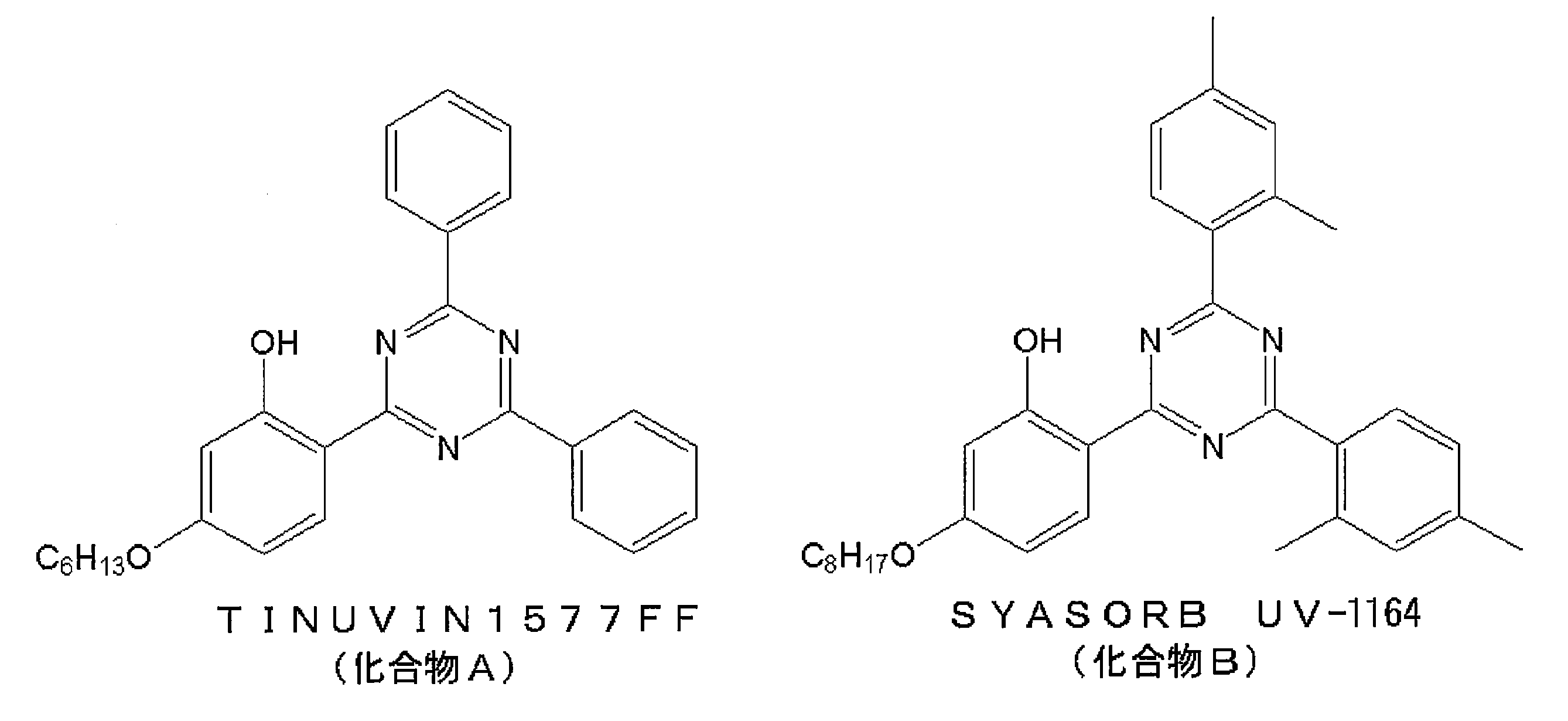
実施例-1~実施例-32
<ポリエチレンテレフタレートフィルムの作製>
-ポリエステルの合成-
高純度テレフタル酸(三井化学(株)製)100kgとエチレングリコール(日本触媒(株)製)45kgのスラリーを、予めビス(ヒドロキシエチル)テレフタレート約123kgが仕込まれ、温度250℃、圧力1.2×10⁵Paに保持されたエステル化反応槽に、4時間かけて順次供給し、供給終了後もさらに1時間かけてエステル化反応を行なった。その後、得られたエステル化反応生成物123kgを重縮合反応槽に移送した。
<ポリエチレンテレフタレートフィルムの作製>
-ポリエステルの合成-
高純度テレフタル酸(三井化学(株)製)100kgとエチレングリコール(日本触媒(株)製)45kgのスラリーを、予めビス(ヒドロキシエチル)テレフタレート約123kgが仕込まれ、温度250℃、圧力1.2×10⁵Paに保持されたエステル化反応槽に、4時間かけて順次供給し、供給終了後もさらに1時間かけてエステル化反応を行なった。その後、得られたエステル化反応生成物123kgを重縮合反応槽に移送した。
引き続いて、エステル化反応生成物が移送された重縮合反応槽に、エチレングリコールを、得られるポリマーに対して0.3質量%添加した。5分間撹拌した後、酢酸コバルト及び酢酸マンガンのエチレングリコール溶液を、得られるポリマーに対してそれぞれ30ppm、15ppmとなるように加えた。更に5分間撹拌した後、チタンアルコキシド化合物の2質量%エチレングリコール溶液を、得られるポリマーに対して5ppmとなるように添加した。前記チタンアルコキシド化合物には、特開2005-340616号公報の段落番号[0083]の実施例1で合成しているチタンアルコキシド化合物(Ti含有量=4.44質量%)を用いた。その5分後、ジエチルホスホノ酢酸エチルの10質量%エチレングリコール溶液を、得られるポリマーに対して5ppmとなるように添加した。
その後、低重合体を30rpmで攪拌しながら、反応系を250℃から285℃まで徐々に昇温するとともに、圧力を40Paまで下げた。最終温度、最終圧力到達までの時間はともに60分とした。所定の攪拌トルク(97Kg・cm)となった時点で反応系を窒素パージし、常圧に戻し、重縮合反応を停止した。なお、減圧開始から所定の撹拌トルク到達までの時間は3時間であった。
そして、得られたポリマー溶融物を冷水にストランド状に吐出し、直ちにカッティングしてポリマーのペレット(直径約3mm、長さ約7mm)を作製した。
そして、得られたポリマー溶融物を冷水にストランド状に吐出し、直ちにカッティングしてポリマーのペレット(直径約3mm、長さ約7mm)を作製した。
-固相重合-
上記で得られたペレットを、40Paに保たれた真空容器中、220℃の温度で30時間保持して、固相重合を行なった。
上記で得られたペレットを、40Paに保たれた真空容器中、220℃の温度で30時間保持して、固相重合を行なった。
-ベース形成-
以上のように固相重合を経た後のペレットを、280℃で溶融して金属ドラムの上にキャストし、厚さ約2.5mmの未延伸ベースを作成した。その後、90℃で縦方向に3倍に延伸し、更に120℃で横方向に3.3倍に延伸した。こうして、厚み200μmの2軸延伸ポリエチレンテレフタレートフィルム(ポリエチレンテレフタレートフィルム)を得た。
以上のように固相重合を経た後のペレットを、280℃で溶融して金属ドラムの上にキャストし、厚さ約2.5mmの未延伸ベースを作成した。その後、90℃で縦方向に3倍に延伸し、更に120℃で横方向に3.3倍に延伸した。こうして、厚み200μmの2軸延伸ポリエチレンテレフタレートフィルム(ポリエチレンテレフタレートフィルム)を得た。
<UV吸収剤コーティング付き基材フィルムの作成>
シロキサン系バインダーとしてアルコキシシリコーンオリゴマー(信越化学工業株式会社製、X-40-9250)100重量部、チタン系硬化触媒(信越化学工業株式会社製、D-20)5重量部、メチルエチルケトン100重量部を混合して調整した。さらに、表1に示した紫外線吸収剤を20重量部添加してコーティング液を調製した。次に、上記の200μmのポリエチレンテレフタレートフィルムの上に、上記コーティング剤を乾燥膜厚で6.3μmとなるように塗布し、室温で6時間乾燥させて、それぞれのUV吸収剤コーティング付きフィルム(A)をそれぞれ作成した。
シロキサン系バインダーとしてアルコキシシリコーンオリゴマー(信越化学工業株式会社製、X-40-9250)100重量部、チタン系硬化触媒(信越化学工業株式会社製、D-20)5重量部、メチルエチルケトン100重量部を混合して調整した。さらに、表1に示した紫外線吸収剤を20重量部添加してコーティング液を調製した。次に、上記の200μmのポリエチレンテレフタレートフィルムの上に、上記コーティング剤を乾燥膜厚で6.3μmとなるように塗布し、室温で6時間乾燥させて、それぞれのUV吸収剤コーティング付きフィルム(A)をそれぞれ作成した。
<水蒸気バリアフィルムの作成>
厚み50μmのポリエチレンテレフタレートフィルム上に、下に示した重合性化合物(合計14重量部)と重合開始剤(チバスペシャリティケミカルズ社製、IRGACURE907、1重量部)、2-ブタノン(185重量部)とからなる組成物をワイヤーバーにて塗布し、窒素100ppm雰囲気下、紫外線照射量0.5J/cm2で照射して硬化させ、有機層を作製した。有機層の膜厚は500nmであった。次に、有機層の表面に膜厚が40nmとなるようにAl2O3を真空スパッタ(反応性スパッタリング)で製膜した。次に、このAl2O3上に上と同様にして有機ポリマー層を形成して水蒸気バリアフィルム(B)を得た。
厚み50μmのポリエチレンテレフタレートフィルム上に、下に示した重合性化合物(合計14重量部)と重合開始剤(チバスペシャリティケミカルズ社製、IRGACURE907、1重量部)、2-ブタノン(185重量部)とからなる組成物をワイヤーバーにて塗布し、窒素100ppm雰囲気下、紫外線照射量0.5J/cm2で照射して硬化させ、有機層を作製した。有機層の膜厚は500nmであった。次に、有機層の表面に膜厚が40nmとなるようにAl2O3を真空スパッタ(反応性スパッタリング)で製膜した。次に、このAl2O3上に上と同様にして有機ポリマー層を形成して水蒸気バリアフィルム(B)を得た。
重合性化合物の組成
以下に示す化合物A~Dを以下に示す割合で用いた。
化合物A:共栄社化学(株)製、ライトアクリレート1,9-ND-A:50質量%

化合物B:ダイセルサイテック(株)製、TMPTA:30質量%

化合物C:ダイセルサイテック(株)製、IRR=214K:10質量%

化合物D:日本化薬(株)製、KAYARAD、PM-21:10質量%

以下に示す化合物A~Dを以下に示す割合で用いた。
化合物A:共栄社化学(株)製、ライトアクリレート1,9-ND-A:50質量%
上記UV吸収剤コーティング付きフィルム(A)の未塗布面と水蒸気バリアフィルム(B)のAl2O3膜側をウレタン系接着剤(三井化学製、タケラックA971)を介して貼り合わせ、試料(C-1)~(C-32)を得た。
得られた保護フィルムについて、下記項目に従って評価を行った。
[全光線透過率]
JIS K7361-1に準じて、ヘイズメーター(日本電色工業株式会社製 NDH 5000)を用いて、全光線透過率を測定した。
JIS K7361-1に準じて、ヘイズメーター(日本電色工業株式会社製 NDH 5000)を用いて、全光線透過率を測定した。
[水蒸気バリア性評価]
G.NISATO、P.C.P.BOUTEN、P.J.SLIKKERVEERらSID Conference Record of the International Display Research Conference 1435-1438頁に記載の方法を用いて水蒸気透過率(g/m2/day)を測定した。このときの温度は40℃、相対湿度は90%とした。得られた結果は以下のように評価し、まとめた。
(評価)
1 :3.0g/m2/day以上
2 :1.0g/m2/day以上3.0g/m2/day未満
3 :0.1g/m2/day以上1.0g/m2/day未満
4 :0.01g/m2/day以上0.1g/m2/day未満
5 :0.001g/m2/day未満
G.NISATO、P.C.P.BOUTEN、P.J.SLIKKERVEERらSID Conference Record of the International Display Research Conference 1435-1438頁に記載の方法を用いて水蒸気透過率(g/m2/day)を測定した。このときの温度は40℃、相対湿度は90%とした。得られた結果は以下のように評価し、まとめた。
(評価)
1 :3.0g/m2/day以上
2 :1.0g/m2/day以上3.0g/m2/day未満
3 :0.1g/m2/day以上1.0g/m2/day未満
4 :0.01g/m2/day以上0.1g/m2/day未満
5 :0.001g/m2/day未満
[密着性評価]
保護フィルムの密着性評価は、JIS K5400に準拠した碁盤目試験により行なった。保護フィルムの表面にそれぞれカッターナイフで膜面に対して90°の切込みを1mm間隔で入れ、1mm間隔の碁盤目を100個作製した。この上に2cm幅のマイラーテープ[日東電工製、ポリエステルテープ(No.31B)]を貼り付け、テープ剥離試験機を使用して貼り付けたテープをはがした。保護フィルム上の100個の碁盤目のうち剥離せずに残存したマスの数(n)をカウントした。得られた結果は以下のように評価し、まとめた。
残存数N=n/100
(評価)
1:N < 0.2
2:0.21 ≦ N ≦ 0.5
3:0.51 ≦ N ≦ 0.7
4:0.71 ≦ N ≦ 0.9
5:0.91 ≦ N
保護フィルムの密着性評価は、JIS K5400に準拠した碁盤目試験により行なった。保護フィルムの表面にそれぞれカッターナイフで膜面に対して90°の切込みを1mm間隔で入れ、1mm間隔の碁盤目を100個作製した。この上に2cm幅のマイラーテープ[日東電工製、ポリエステルテープ(No.31B)]を貼り付け、テープ剥離試験機を使用して貼り付けたテープをはがした。保護フィルム上の100個の碁盤目のうち剥離せずに残存したマスの数(n)をカウントした。得られた結果は以下のように評価し、まとめた。
残存数N=n/100
(評価)
1:N < 0.2
2:0.21 ≦ N ≦ 0.5
3:0.51 ≦ N ≦ 0.7
4:0.71 ≦ N ≦ 0.9
5:0.91 ≦ N
[耐紫外線性]
各評価に対して、サンプル作成後の評価、およびメタリングバーチカルウェザーメーター(スガ試験機製 MV3000)を用いて0.53kW/m2(波長:300~400nm)、ブラックパネル温度63℃、槽内湿度50%で2000時間、試験用サンプルに対して紫外線暴露試験を実施した後の評価を行った。および、高温高湿槽中で85℃、85RH%の環境下1000時間放置してから取り出し、室温で乾燥させた後のb値の評価を行った。
得られた結果を下記表に示す。
各評価に対して、サンプル作成後の評価、およびメタリングバーチカルウェザーメーター(スガ試験機製 MV3000)を用いて0.53kW/m2(波長:300~400nm)、ブラックパネル温度63℃、槽内湿度50%で2000時間、試験用サンプルに対して紫外線暴露試験を実施した後の評価を行った。および、高温高湿槽中で85℃、85RH%の環境下1000時間放置してから取り出し、室温で乾燥させた後のb値の評価を行った。
得られた結果を下記表に示す。
比較例-1
紫外線吸収剤を添加しない以外は実施例-1と同様にして比較例-1を実施して、実施例-1と同様の評価を行った。結果を下記表に示す。
紫外線吸収剤を添加しない以外は実施例-1と同様にして比較例-1を実施して、実施例-1と同様の評価を行った。結果を下記表に示す。
比較例-2、比較例-3
紫外線吸収剤として下記の二酸化チタン(タイペークR-780-2、石原産業(株)製)を用いて、添加量を表のように変える以外は実施例-1と同様にして比較例-2、3を実施して、実施例-1と同様の評価を行った。結果を下記表に示す。
紫外線吸収剤として下記の二酸化チタン(タイペークR-780-2、石原産業(株)製)を用いて、添加量を表のように変える以外は実施例-1と同様にして比較例-2、3を実施して、実施例-1と同様の評価を行った。結果を下記表に示す。
実施例-33
厚さ50μmの代わりに厚み200μmのポリエチレンテレフタレートフィルムを用いて、実施例-1と同様にして水蒸気バリアフィルムを作成した。この水蒸気バリア層が形成されている面の反対面に、実施例-26で用いたUV吸収剤コーティングを形成して試料を得た。
この試料は、200μmのポリエチレンテレフタレートフィルムの、一方の面にUV吸収剤コーティングが形成され、この反対の面に水蒸気バリア層が形成された試料である。
この試料についても、実施例-1と同様の評価を行った。結果を下記表に示す。
厚さ50μmの代わりに厚み200μmのポリエチレンテレフタレートフィルムを用いて、実施例-1と同様にして水蒸気バリアフィルムを作成した。この水蒸気バリア層が形成されている面の反対面に、実施例-26で用いたUV吸収剤コーティングを形成して試料を得た。
この試料は、200μmのポリエチレンテレフタレートフィルムの、一方の面にUV吸収剤コーティングが形成され、この反対の面に水蒸気バリア層が形成された試料である。
この試料についても、実施例-1と同様の評価を行った。結果を下記表に示す。
実施例-34
実施例-26でUV吸収剤コーティングのコーティング液の組成と形成条件を下記のように変更する以外は実施例-26と同様にして実施例-34を実施した。
-コーティング液の組成-
・アクリル/シリコーン系バインダー・・・456.5質量部
(セラネートWSA-1070、DIC(株)製、固形分:40質量%)
・カルボジイミド化合物(架橋剤)・・・23.3質量部
(カルボジライトV-02-L2、日清紡績(株)製、固形分:40質量%)
・オキサゾリン化合物(架橋剤)・・・37.2質量部
(エポクロスWS700、(株)日本触媒製、固形分:25質量%)
・界面活性剤・・・9.7質量部
(ナロアクティーCL95、三洋化成工業(株)製、固形分:1質量%)
・化合物m-21分散物・・・241.5質量%
・蒸留水・・・231.8質量部
実施例-26でUV吸収剤コーティングのコーティング液の組成と形成条件を下記のように変更する以外は実施例-26と同様にして実施例-34を実施した。
-コーティング液の組成-
・アクリル/シリコーン系バインダー・・・456.5質量部
(セラネートWSA-1070、DIC(株)製、固形分:40質量%)
・カルボジイミド化合物(架橋剤)・・・23.3質量部
(カルボジライトV-02-L2、日清紡績(株)製、固形分:40質量%)
・オキサゾリン化合物(架橋剤)・・・37.2質量部
(エポクロスWS700、(株)日本触媒製、固形分:25質量%)
・界面活性剤・・・9.7質量部
(ナロアクティーCL95、三洋化成工業(株)製、固形分:1質量%)
・化合物m-21分散物・・・241.5質量%
・蒸留水・・・231.8質量部
-形成条件-
ウェット塗布量が34.5cc/m2になるよう塗布した後、175℃で3分間乾燥させた。
ウェット塗布量が34.5cc/m2になるよう塗布した後、175℃で3分間乾燥させた。
-化合物(m-21)の分散物の調製-
酢酸エチル35.4gとテトラヒドロフラン8.8gを混合した混合溶媒に、化合物(m-21)を18.9g添加し、50℃に加熱し10分間攪拌して化合物(A-1)を溶解して油相液を調整した。
400ccのステンレス容器に蒸留水116.5gを添加し、90℃に加熱した。続いて、クラレポバールPVA-205(ポリビニルアルコール、クラレ(株)製)20.5gを添加し、90℃で3時間攪拌し溶解させ、水相液を得た。
続いて水相液を、ディゾルバーを用いて500rpmで攪拌しながら、油相液を添加した。添加後、更に5分間攪拌を続けて均一な液とした。
得られた均一な液を、さらにディゾルバーを用いて20,000rpmで10分攪拌し、乳化物1を得た。得られた乳化物1の平均粒子径を測定したところ、メジアン径120nmであった。
乳化物1からエバポレーターを用いて有機溶剤を留去して、分散物1を得た。残留した溶剤の量をガスクロマトグラフィによって測定したところ、0.7%以下であった。分散物1の平均粒子径を測定したところ、メジアン径121nmであった。
この試料について、実施例-1と同様の評価を行った。結果を下記表に示す。
酢酸エチル35.4gとテトラヒドロフラン8.8gを混合した混合溶媒に、化合物(m-21)を18.9g添加し、50℃に加熱し10分間攪拌して化合物(A-1)を溶解して油相液を調整した。
400ccのステンレス容器に蒸留水116.5gを添加し、90℃に加熱した。続いて、クラレポバールPVA-205(ポリビニルアルコール、クラレ(株)製)20.5gを添加し、90℃で3時間攪拌し溶解させ、水相液を得た。
続いて水相液を、ディゾルバーを用いて500rpmで攪拌しながら、油相液を添加した。添加後、更に5分間攪拌を続けて均一な液とした。
得られた均一な液を、さらにディゾルバーを用いて20,000rpmで10分攪拌し、乳化物1を得た。得られた乳化物1の平均粒子径を測定したところ、メジアン径120nmであった。
乳化物1からエバポレーターを用いて有機溶剤を留去して、分散物1を得た。残留した溶剤の量をガスクロマトグラフィによって測定したところ、0.7%以下であった。分散物1の平均粒子径を測定したところ、メジアン径121nmであった。
この試料について、実施例-1と同様の評価を行った。結果を下記表に示す。
実施例-35
UV吸収剤コーティングとして実施例-34と同じものを使う以外は実施例-33と同様にして実施例-35を実施した。
この試料について、実施例-1と同様の評価を行った。結果を下記表に示す。
UV吸収剤コーティングとして実施例-34と同じものを使う以外は実施例-33と同様にして実施例-35を実施した。
この試料について、実施例-1と同様の評価を行った。結果を下記表に示す。
上記結果から明らかなとおり、有機系紫外線吸収剤を含有したコーティング層を樹脂フィルム側の表面に設置することにより、可視光透過率が高く、紫外線照射後の基材の着色が抑制されることが確認された。有機系紫外線吸収剤の中でも、トリアジン環構造を有する化合物を採用することにより、これらの効果がより発揮されることが確認された。

太陽電池モジュールの作成
-バックシートの作成-
-二酸化チタン分散物の調製-
下記組成中の各成分を混合し、その混合物をダイノミル型分散機により1時間、分散処理を施した。
(二酸化チタン分散物の組成)
・二酸化チタン(体積平均粒子径=0.42μm)・・・40質量%
(タイペークR-780-2、石原産業(株)製、固形分100質量%)
・ポリビニルアルコール水溶液(10質量%)・・・8.0質量%
(PVA-105、(株)クラレ製)
・界面活性剤(デモールEP、花王(株)製、固形分:25質量%)・・・0.5質量%
・蒸留水・・・51.5質量%
-バックシートの作成-
-二酸化チタン分散物の調製-
下記組成中の各成分を混合し、その混合物をダイノミル型分散機により1時間、分散処理を施した。
(二酸化チタン分散物の組成)
・二酸化チタン(体積平均粒子径=0.42μm)・・・40質量%
(タイペークR-780-2、石原産業(株)製、固形分100質量%)
・ポリビニルアルコール水溶液(10質量%)・・・8.0質量%
(PVA-105、(株)クラレ製)
・界面活性剤(デモールEP、花王(株)製、固形分:25質量%)・・・0.5質量%
・蒸留水・・・51.5質量%
<裏面下塗り層>
-裏面下塗り層形成用塗布液の調製-
下記組成中の各成分を混合し、裏面下塗り層形成用塗布液を調製した。
(塗布液の組成)
・シリコーンアクリル系バインダー・・・396.5質量部
(セラネートWSA1070、DIC(株)製、固形分:40質量%)
・二酸化チタン分散物・・・493.9質量部
・カルボジイミド化合物(架橋剤)・・・49.0質量部
(カルボジライトV-02-L2、日清紡績(株)製、固形分:40質量%)
・オキサゾリン化合物(架橋剤)・・・16.8質量部
(エポクロスWS700、(株)日本触媒製、固形分:25質量%)
・界面活性剤・・・15.0質量部
(ナロアクティーCL95、三洋化成工業(株)製、固形分:1質量%)
・蒸留水・・・28.8質量部
-裏面下塗り層形成用塗布液の調製-
下記組成中の各成分を混合し、裏面下塗り層形成用塗布液を調製した。
(塗布液の組成)
・シリコーンアクリル系バインダー・・・396.5質量部
(セラネートWSA1070、DIC(株)製、固形分:40質量%)
・二酸化チタン分散物・・・493.9質量部
・カルボジイミド化合物(架橋剤)・・・49.0質量部
(カルボジライトV-02-L2、日清紡績(株)製、固形分:40質量%)
・オキサゾリン化合物(架橋剤)・・・16.8質量部
(エポクロスWS700、(株)日本触媒製、固形分:25質量%)
・界面活性剤・・・15.0質量部
(ナロアクティーCL95、三洋化成工業(株)製、固形分:1質量%)
・蒸留水・・・28.8質量部
-裏面下塗り層の形成-
得られた裏面下塗り層形成用塗布液をPET基材の一方の面に、バインダー量が塗布量で5.4g/m2になるように塗布し、180℃で1分間乾燥させて、乾燥厚みが約7.1μmの下塗り層を形成した。
得られた裏面下塗り層形成用塗布液をPET基材の一方の面に、バインダー量が塗布量で5.4g/m2になるように塗布し、180℃で1分間乾燥させて、乾燥厚みが約7.1μmの下塗り層を形成した。
<含フッ素ポリマー層>
-含フッ素ポリマー層形成用塗布液の調製-
下記組成中の各成分を混合し、含フッ素ポリマー層形成用塗布液を調製した。
(塗布液の組成)
・オブリガートSW0011F(バインダー)・・・345.0質量部
(フッ素系バインダー、AGCコーテック(株)製、固形分:36質量%)
・カルボジイミド化合物(架橋剤、A-1)・・・62.3質量部
(カルボジライトV-02-L2、日清紡績(株)製、固形分:40質量%)
・界面活性剤・・・60.0質量部
(ナロアクティーCL95、三洋化成工業(株)製、固形分:1質量%)
・コロイダルシリカ・・・3.9質量部
(スノーテックスUP、日産化学(株)製、固形分20質量%)
・シランカップリング剤・・・78.5質量部
(TSL8340、モメンティブ・パーフォマンス・マテリアルズ・ジャパン合同会社製、固形分1質量%)
・低分子量ポリオレフィンワックス水分散物・・・207.6質量部
(ケミパールW950、三井化学(株)製、固形分5質量%)
・蒸留水・・・242.7質量部
-含フッ素ポリマー層形成用塗布液の調製-
下記組成中の各成分を混合し、含フッ素ポリマー層形成用塗布液を調製した。
(塗布液の組成)
・オブリガートSW0011F(バインダー)・・・345.0質量部
(フッ素系バインダー、AGCコーテック(株)製、固形分:36質量%)
・カルボジイミド化合物(架橋剤、A-1)・・・62.3質量部
(カルボジライトV-02-L2、日清紡績(株)製、固形分:40質量%)
・界面活性剤・・・60.0質量部
(ナロアクティーCL95、三洋化成工業(株)製、固形分:1質量%)
・コロイダルシリカ・・・3.9質量部
(スノーテックスUP、日産化学(株)製、固形分20質量%)
・シランカップリング剤・・・78.5質量部
(TSL8340、モメンティブ・パーフォマンス・マテリアルズ・ジャパン合同会社製、固形分1質量%)
・低分子量ポリオレフィンワックス水分散物・・・207.6質量部
(ケミパールW950、三井化学(株)製、固形分5質量%)
・蒸留水・・・242.7質量部
-含フッ素ポリマー層の形成-
得られた含フッ素ポリマー層形成用塗布液をPET基材の片面に設けた裏面下塗り層の上に、バインダー量が塗布量で2.0g/m2になるように塗布し、180℃で1分間乾燥させて、乾燥厚み約2μmの含フッ素ポリマー層を形成した。
得られた含フッ素ポリマー層形成用塗布液をPET基材の片面に設けた裏面下塗り層の上に、バインダー量が塗布量で2.0g/m2になるように塗布し、180℃で1分間乾燥させて、乾燥厚み約2μmの含フッ素ポリマー層を形成した。
<表面下塗り層>
(塗布液の組成)
・アクリル系バインダー・・・25.7質量部
(EM48D、ダイセル(株)製、固形分:28質量%)
・ポリオレフィン系バインダー・・・35.6質量部
(アローベースSE1013N、ユニチカ(株)製、固形分:20質量%)
・カルボジイミド化合物(架橋剤)・・・23.3質量部
(カルボジライトV-02-L2、日清紡績(株)製、固形分:40質量%)
・オキサゾリン化合物(架橋剤)・・・37.2質量部
(エポクロスWS700、(株)日本触媒製、固形分:25質量%)
・界面活性剤・・・9.7質量部
(ナロアクティーCL95、三洋化成工業(株)製、固形分:1質量%)
・化合物m-21分散物・・・241.5質量%
・蒸留水・・・231.8質量部
-表面下塗り層の形成-
得られた表面下塗り層形成用塗布液をPET基材の裏面下塗り層の設けられた面の反対面に、バインダー量が塗布量で0.12g/m2になるように塗布し、180℃で1分間乾燥させて、乾燥厚みが約0.12μmの下塗り層を形成した。
(塗布液の組成)
・アクリル系バインダー・・・25.7質量部
(EM48D、ダイセル(株)製、固形分:28質量%)
・ポリオレフィン系バインダー・・・35.6質量部
(アローベースSE1013N、ユニチカ(株)製、固形分:20質量%)
・カルボジイミド化合物(架橋剤)・・・23.3質量部
(カルボジライトV-02-L2、日清紡績(株)製、固形分:40質量%)
・オキサゾリン化合物(架橋剤)・・・37.2質量部
(エポクロスWS700、(株)日本触媒製、固形分:25質量%)
・界面活性剤・・・9.7質量部
(ナロアクティーCL95、三洋化成工業(株)製、固形分:1質量%)
・化合物m-21分散物・・・241.5質量%
・蒸留水・・・231.8質量部
-表面下塗り層の形成-
得られた表面下塗り層形成用塗布液をPET基材の裏面下塗り層の設けられた面の反対面に、バインダー量が塗布量で0.12g/m2になるように塗布し、180℃で1分間乾燥させて、乾燥厚みが約0.12μmの下塗り層を形成した。
<反射層/(易接着層を兼ねている)>
-反射層形成用塗布液の調製-
下記組成中の各成分を混合し、反射層形成用塗布液を調製した。
(塗布液の組成)
・二酸化チタン分散物・・・357.6質量部
(裏面下塗り層で用いたものと共通)
・ポリオレフィン系バインダー・・・514.5質量部
(アローベースSE1013N、ユニチカ(株)製、固形分:20質量%)
・オキサゾリン化合物(架橋剤)・・・52.8質量部
(エポクロスWS700、(株)日本触媒製、固形分:25質量%)
・界面活性剤・・・28.0質量部
(ナロアクティーCL95、三洋化成工業(株)製、固形分:1質量%)
・蒸留水・・・47.1質量部
-反射層形成用塗布液の調製-
下記組成中の各成分を混合し、反射層形成用塗布液を調製した。
(塗布液の組成)
・二酸化チタン分散物・・・357.6質量部
(裏面下塗り層で用いたものと共通)
・ポリオレフィン系バインダー・・・514.5質量部
(アローベースSE1013N、ユニチカ(株)製、固形分:20質量%)
・オキサゾリン化合物(架橋剤)・・・52.8質量部
(エポクロスWS700、(株)日本触媒製、固形分:25質量%)
・界面活性剤・・・28.0質量部
(ナロアクティーCL95、三洋化成工業(株)製、固形分:1質量%)
・蒸留水・・・47.1質量部
-反射層の形成-
得られた反射層形成用塗布液をPET基材上に設けた表面下塗り層の上に、バインダー量が塗布量で3.1g/m2になるように塗布し、180℃で1分間乾燥させて、乾燥厚み約6μmの反射層を形成した。
得られた反射層形成用塗布液をPET基材上に設けた表面下塗り層の上に、バインダー量が塗布量で3.1g/m2になるように塗布し、180℃で1分間乾燥させて、乾燥厚み約6μmの反射層を形成した。
-太陽電池モジュールの作成-
実施例-1の試料のUV吸収剤コーティングが形成されている面の反対面に以下の条件でコロナ処理を行った。
装置:ピラー社製ソリッドステートコロナ処理機6KVAモデル
電極と誘電体ロールギャップクリアランス:1.6mm
処理周波数:9.6kHz
処理速度:20m/分
処理強度:0.375kV・A・分/m2
この試料と、上で述べたバックシート、EVAシート(三井化学ファブロ(株)製のSC50B、封止材)と、結晶系太陽電池セルと、EVAシート(三井化学ファブロ(株)製のSC50B)と、前述のバックシートと、をこの順に重ね合わせ、真空ラミネータ(日清紡(株)製、真空ラミネート機)を用いてホットプレスすることにより、バックシートとEVAシートとを接着させた。
このとき、実施例-1の試料のコロナ処理面がEVAシートと接する形で、またバックシートは反射層が形成された面がEVAシートと接する形でホットプレスした。
また、EVAの接着条件は、以下の通りである。
真空ラミネータを用いて、128℃で3分間の真空引き後、2分間加圧して仮接着した。その後、ドライオーブンにて150℃で30分間、本接着処理を施した。
実施例-1の試料のUV吸収剤コーティングが形成されている面の反対面に以下の条件でコロナ処理を行った。
装置:ピラー社製ソリッドステートコロナ処理機6KVAモデル
電極と誘電体ロールギャップクリアランス:1.6mm
処理周波数:9.6kHz
処理速度:20m/分
処理強度:0.375kV・A・分/m2
この試料と、上で述べたバックシート、EVAシート(三井化学ファブロ(株)製のSC50B、封止材)と、結晶系太陽電池セルと、EVAシート(三井化学ファブロ(株)製のSC50B)と、前述のバックシートと、をこの順に重ね合わせ、真空ラミネータ(日清紡(株)製、真空ラミネート機)を用いてホットプレスすることにより、バックシートとEVAシートとを接着させた。
このとき、実施例-1の試料のコロナ処理面がEVAシートと接する形で、またバックシートは反射層が形成された面がEVAシートと接する形でホットプレスした。
また、EVAの接着条件は、以下の通りである。
真空ラミネータを用いて、128℃で3分間の真空引き後、2分間加圧して仮接着した。その後、ドライオーブンにて150℃で30分間、本接着処理を施した。
このようにして、実施例-1で得られた試料をフロントシートに用いた結晶系の太陽電池モジュールを得た。同様にして実施例-2、3、20、26、33、34、35の試料を用いて太陽電池モジュールを作製した。この太陽電池モジュールはガラス板を使用していないため、軽量であった。
作製した太陽電池モジュールを用いて発電運転をしたところ、いずれの太陽電池モジュールについても、太陽電池として良好な発電性能を示した。
また、太陽電池モジュールを、120℃、100%RHの雰囲気下に48時間保持した後も、フロントシートとバックシートの剥離や変色は見られず、良好な外観を保っていた。
さらにこれらの太陽電池モジュールを用いて発電運転をしたところ、いずれの太陽電池モジュールについても、湿熱条件保持前と同様な発電性能を示した。
作製した太陽電池モジュールを用いて発電運転をしたところ、いずれの太陽電池モジュールについても、太陽電池として良好な発電性能を示した。
また、太陽電池モジュールを、120℃、100%RHの雰囲気下に48時間保持した後も、フロントシートとバックシートの剥離や変色は見られず、良好な外観を保っていた。
さらにこれらの太陽電池モジュールを用いて発電運転をしたところ、いずれの太陽電池モジュールについても、湿熱条件保持前と同様な発電性能を示した。
本発明の保護フィルムは、透過率、水蒸気バリア性、密着性、接着性および耐屈曲性に総合的に優れている。そのため、太陽電池用保護シート部材、特に、フロントシート用部材として好ましく用いることができる。
また、本発明の保護フィルムは、長期間の紫外線暴露に耐えうる耐候性保護フィルムとすることができる。具体的には、長期間の紫外線暴露後、高温高湿度暴露後でも水蒸気バリア性、フィルム強度、透過率などが維持できる保護フィルムとすることができる。ここで、フィルム強度とは、フィルムの接着性、フィルムの密着性、さらには屈曲した際の表面クラック耐性などを指す。
さらに、表面コーティング層に有機系紫外線吸収剤を含有させることで、高温高湿度下でのフィルム強度が維持できる。
また、本発明の保護フィルムは、長期間の紫外線暴露に耐えうる耐候性保護フィルムとすることができる。具体的には、長期間の紫外線暴露後、高温高湿度暴露後でも水蒸気バリア性、フィルム強度、透過率などが維持できる保護フィルムとすることができる。ここで、フィルム強度とは、フィルムの接着性、フィルムの密着性、さらには屈曲した際の表面クラック耐性などを指す。
さらに、表面コーティング層に有機系紫外線吸収剤を含有させることで、高温高湿度下でのフィルム強度が維持できる。
1 コーティング層
2 樹脂フィルム
3 水蒸気ガスバリアフィルム
4 接着層
7 フロントシート層
8 充填接着樹脂層
9 太陽電池素子要部
10 充填接着樹脂層
11 バックシート層
2 樹脂フィルム
3 水蒸気ガスバリアフィルム
4 接着層
7 フロントシート層
8 充填接着樹脂層
9 太陽電池素子要部
10 充填接着樹脂層
11 バックシート層
Claims (20)
- 水蒸気ガスバリアフィルムと、樹脂フィルムと、有機系紫外線吸収剤を含有するコーティング層とを、該順に有する保護フィルム。
- コーティング層が、樹脂フィルムの表面に設けられている請求項1に記載の保護フィルム。
- 有機系紫外線吸収剤が、芳香族系紫外線吸収剤である、請求項1または2に記載の保護フィルム。
- 有機系紫外線吸収剤が、トリアジン環構造を有する化合物である、請求項1または2に記載の保護フィルム。
- 有機系紫外線吸収剤が、下記一般式(1)で表される化合物である、請求項1または2に記載の保護フィルム。
一般式(1)

- 前記1価の置換基が、ハロゲン原子、置換又は無置換の炭素数1~20のアルキル基、シアノ基、カルボキシル基、置換又は無置換のアルコキシカルボニル基、置換又は無置換のカルバモイル基、置換又は無置換のアルキルカルボニル基、ニトロ基、置換又は無置換のアミノ基、ヒドロキシ基、炭素数1~20のアルコキシ基、置換又は無置換のアリールオキシ基、置換又は無置換のスルファモイル基、チオシアネート基、又は置換又は無置換のアルキルスルホニル基であり、置換基を有する場合の置換基がハロゲン原子、炭素数1~20のアルキル基、シアノ基、カルボキシル基、アルコキシカルボニル基、カルバモイル基、アルキルカルボニル基、ニトロ基、アミノ基、ヒドロキシ基、炭素数1~20のアルコキシ基、アリールオキシ基、スルファモイル基、チオシアネート基、又はアルキルスルホニル基であることを特徴とする、請求項5に記載の保護フィルム。
- 前記R1cが、ハメット則のσp値が正である置換基であることを特徴とする、請求項5または6に記載の保護フィルム。
- 有機系紫外線吸収剤が、下記一般式(2)で表される化合物である、請求項1または2に記載の保護フィルム。
一般式(2)
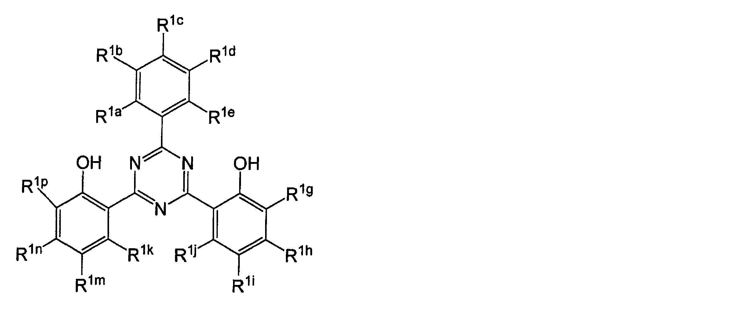
- 前記一般式(2)で表される紫外線吸収剤における1価の置換基が、ハロゲン原子、置換又は無置換の炭素数1~20のアルキル基、シアノ基、カルボキシル基、置換又は無置換のアルコキシカルボニル基、置換又は無置換のカルバモイル基、置換又は無置換のアルキルカルボニル基、ニトロ基、置換又は無置換のアミノ基、ヒドロキシ基、炭素数1~20のアルコキシ基、置換又は無置換のアリールオキシ基、置換又は無置換のスルファモイル基、チオシアネート基、又は置換又は無置換のアルキルスルホニル基であり、置換基を有する場合の置換基がハロゲン原子、炭素数1~20のアルキル基、シアノ基、カルボキシル基、アルコキシカルボニル基、カルバモイル基、アルキルカルボニル基、ニトロ基、アミノ基、ヒドロキシ基、炭素数1~20のアルコキシ基、アリールオキシ基、スルファモイル基、チオシアネート基、又はアルキルスルホニル基であることを特徴とする、請求項8に記載の保護フィルム。
- 前記ハメット則のσp値が、0.1~1.2の範囲であることを特徴とする、請求項8または9に記載の保護フィルム。
- コーティング層がシロキサン系バインダーを含む、請求項1~10のいずれか1項に記載の保護フィルム。
- 水蒸気ガスバリアフィルムが、少なくとも1層の有機層と少なくとも1層の無機層が交互に積層した積層体を含む、請求項1~11のいずれか1項に記載の保護フィルム。
- 無機層が、珪素およびアルミの少なくとも1種と、酸素および窒素の少なくとも1種を含むことを特徴とする、請求項12に記載の保護フィルム。
- 有機層が、(メタ)アクリレートを含む重合性組成物を硬化してなる層である、請求項1~13のいずれか1項に記載の保護フィルム。
- 前記樹脂フィルムが、ポリエチレンテレフタラートフィルム、ポリエチレンナフタレートフィルム、ポリカーボネートフィルム、フッ素樹脂フィルムおよびアクリル樹脂フィルムから選択される、請求項1~14のいずれか1項に記載の保護フィルム。
- 太陽電池の保護シート用部材である、請求項1~15のいずれか1項に記載の保護フィルム。
- 太陽電池のフロントシート用である、請求項1~15のいずれか1項に記載の保護フィルム。
- 請求項1~17のいずれか1項に記載の保護フィルムを含む、太陽電池素子。
- フロントシートとバックシートと、太陽電池素子要部を含む太陽電池素子であって、前記フロントシートが請求項1~17のいずれか1項に記載の保護フィルムであり、前記バックシートは、ポリエステルフィルムと最外層としてシロキサン系バインダーを含有するポリマー層である、太陽電池素子。
- 前記フロントシートに含まれる樹脂フィルムと、前記バックシートに含まれるポリエステルフィルムが、それぞれ、カルボキシル基含量が30等量/トン以下である、請求項19に記載の太陽電池素子。
Applications Claiming Priority (4)
| Application Number | Priority Date | Filing Date | Title |
|---|---|---|---|
| JP2010-268384 | 2010-12-01 | ||
| JP2010268384 | 2010-12-01 | ||
| JP2011148837A JP2012134445A (ja) | 2010-12-01 | 2011-07-05 | 保護フィルム |
| JP2011-148837 | 2011-07-05 |
Publications (1)
| Publication Number | Publication Date |
|---|---|
| WO2012073804A1 true WO2012073804A1 (ja) | 2012-06-07 |
Family
ID=46171743
Family Applications (1)
| Application Number | Title | Priority Date | Filing Date |
|---|---|---|---|
| PCT/JP2011/077139 Ceased WO2012073804A1 (ja) | 2010-12-01 | 2011-11-25 | 保護フィルム |
Country Status (2)
| Country | Link |
|---|---|
| JP (1) | JP2012134445A (ja) |
| WO (1) | WO2012073804A1 (ja) |
Cited By (2)
| Publication number | Priority date | Publication date | Assignee | Title |
|---|---|---|---|---|
| JP2013038412A (ja) * | 2011-07-14 | 2013-02-21 | Fujifilm Corp | 太陽電池用バックシート及びその製造方法、並びに太陽電池モジュール |
| US20230369522A1 (en) * | 2022-05-16 | 2023-11-16 | Sunpower Corporation | Photovoltaic laminate comprising single polymer composite |
Families Citing this family (4)
| Publication number | Priority date | Publication date | Assignee | Title |
|---|---|---|---|---|
| KR101719873B1 (ko) * | 2014-08-28 | 2017-03-24 | 주식회사 엘지화학 | 백시트 |
| JP2016125034A (ja) * | 2015-01-08 | 2016-07-11 | 富士フイルム株式会社 | 樹脂組成物、偏光板保護フィルム、偏光板および表示装置 |
| JP6457371B2 (ja) * | 2015-10-09 | 2019-01-23 | 富士フイルム株式会社 | ガスバリアフィルム、有機電子装置、有機電界発光装置用基板、有機電界発光装置 |
| WO2022145786A1 (ko) * | 2020-12-28 | 2022-07-07 | 코오롱인더스트리 주식회사 | 향상된 내구성과 유연성을 갖는 수분 및 산소 배리어성 적층체 |
Citations (10)
| Publication number | Priority date | Publication date | Assignee | Title |
|---|---|---|---|---|
| JPH0499263A (ja) * | 1990-08-10 | 1992-03-31 | Oike Ind Co Ltd | 積層フイルム |
| JPH04298503A (ja) * | 1990-05-10 | 1992-10-22 | Ciba Geigy Ag | 輻射線硬化性、光安定化組成物 |
| JPH06211813A (ja) * | 1992-12-03 | 1994-08-02 | Ciba Geigy Ag | ビス−またはトリス−2’−ヒドロキシフェニルトリアジン系紫外線吸収剤 |
| JP2002513832A (ja) * | 1998-04-30 | 2002-05-14 | サイテク・テクノロジー・コーポレーシヨン | Uv光からポリマーを防護するための方法及び組成物 |
| JP2006066682A (ja) * | 2004-08-27 | 2006-03-09 | Canon Inc | 太陽電池モジュール |
| JP2006264118A (ja) * | 2005-03-24 | 2006-10-05 | Fuji Photo Film Co Ltd | プラスチックフィルム、ガスバリアフィルム、およびそれを用いた画像表示素子 |
| JP2006324556A (ja) * | 2005-05-20 | 2006-11-30 | Toppan Printing Co Ltd | 太陽電池用バックシートおよびそれを用いた太陽電池モジュール |
| JP2007173449A (ja) * | 2005-12-21 | 2007-07-05 | Toray Advanced Film Co Ltd | 太陽電池モジュール用表面保護シート |
| JP2010153609A (ja) * | 2008-12-25 | 2010-07-08 | Mitsui Chemicals Inc | 太陽電池封止シート、その製造方法およびその用途 |
| JP2010221655A (ja) * | 2009-03-25 | 2010-10-07 | Teijin Dupont Films Japan Ltd | 積層フィルム |
-
2011
- 2011-07-05 JP JP2011148837A patent/JP2012134445A/ja not_active Withdrawn
- 2011-11-25 WO PCT/JP2011/077139 patent/WO2012073804A1/ja not_active Ceased
Patent Citations (10)
| Publication number | Priority date | Publication date | Assignee | Title |
|---|---|---|---|---|
| JPH04298503A (ja) * | 1990-05-10 | 1992-10-22 | Ciba Geigy Ag | 輻射線硬化性、光安定化組成物 |
| JPH0499263A (ja) * | 1990-08-10 | 1992-03-31 | Oike Ind Co Ltd | 積層フイルム |
| JPH06211813A (ja) * | 1992-12-03 | 1994-08-02 | Ciba Geigy Ag | ビス−またはトリス−2’−ヒドロキシフェニルトリアジン系紫外線吸収剤 |
| JP2002513832A (ja) * | 1998-04-30 | 2002-05-14 | サイテク・テクノロジー・コーポレーシヨン | Uv光からポリマーを防護するための方法及び組成物 |
| JP2006066682A (ja) * | 2004-08-27 | 2006-03-09 | Canon Inc | 太陽電池モジュール |
| JP2006264118A (ja) * | 2005-03-24 | 2006-10-05 | Fuji Photo Film Co Ltd | プラスチックフィルム、ガスバリアフィルム、およびそれを用いた画像表示素子 |
| JP2006324556A (ja) * | 2005-05-20 | 2006-11-30 | Toppan Printing Co Ltd | 太陽電池用バックシートおよびそれを用いた太陽電池モジュール |
| JP2007173449A (ja) * | 2005-12-21 | 2007-07-05 | Toray Advanced Film Co Ltd | 太陽電池モジュール用表面保護シート |
| JP2010153609A (ja) * | 2008-12-25 | 2010-07-08 | Mitsui Chemicals Inc | 太陽電池封止シート、その製造方法およびその用途 |
| JP2010221655A (ja) * | 2009-03-25 | 2010-10-07 | Teijin Dupont Films Japan Ltd | 積層フィルム |
Cited By (3)
| Publication number | Priority date | Publication date | Assignee | Title |
|---|---|---|---|---|
| JP2013038412A (ja) * | 2011-07-14 | 2013-02-21 | Fujifilm Corp | 太陽電池用バックシート及びその製造方法、並びに太陽電池モジュール |
| US20230369522A1 (en) * | 2022-05-16 | 2023-11-16 | Sunpower Corporation | Photovoltaic laminate comprising single polymer composite |
| US12074237B2 (en) * | 2022-05-16 | 2024-08-27 | Maxeon Solar Pte. Ltd. | Photovoltaic laminate comprising single polymer composite |
Also Published As
| Publication number | Publication date |
|---|---|
| JP2012134445A (ja) | 2012-07-12 |
Similar Documents
| Publication | Publication Date | Title |
|---|---|---|
| WO2012073804A1 (ja) | 保護フィルム | |
| US20110297221A1 (en) | Solar cell back sheet and method for preparing same | |
| KR101627053B1 (ko) | 폴리에스테르 필름 및 그 제조 방법, 태양 전지용 백 시트, 그리고 태양 전지 모듈 | |
| EP2527399A1 (en) | Polyester resin composition | |
| CN103443933B (zh) | 太阳能电池用背板及其制造方法、以及太阳能电池模块 | |
| US9985155B2 (en) | Backsheet for photovoltaic modules | |
| JP5762621B2 (ja) | 光電子デバイスおよびそれらのための被膜、ならびにそれらの作製および使用方法 | |
| CN101909768A (zh) | 用于光伏组件的背板 | |
| KR101804715B1 (ko) | 이미노에터 화합물, 폴리에스터 수지 조성물, 카복실산 에스터를 생성하는 방법, 폴리에스터 필름, 태양전지 모듈용 백시트 및 태양전지 모듈 | |
| EP2746322B1 (en) | A back sheet for photovoltaic modules | |
| CN103843153A (zh) | 太阳能电池背面保护片及太阳能电池模块 | |
| KR20180093041A (ko) | 조성물, 막, 유리 물품, 화합물, 고순도 조성물, 화합물의 제조 방법 및 막의 제조 방법 | |
| CN103430321B (zh) | 太阳能电池用聚合物板及其制造方法、太阳能电池用背板、以及太阳能电池模块 | |
| JP2012131214A (ja) | 保護フィルム | |
| JP5606956B2 (ja) | 太陽電池用バックシート及びその製造方法、並びに太陽電池モジュール | |
| CN104781340B (zh) | 烯酮亚胺化合物、聚酯膜、太阳能电池模块用背板及太阳能电池模块 | |
| JP2012122000A (ja) | ポリエステルフィルム及びその製造方法、太陽電池用バックシート並びに太陽電池モジュール | |
| KR101713872B1 (ko) | 폴리에스테르 수지의 제조 방법, 폴리에스테르 필름, 폴리에스테르 필름의 제조 방법, 태양 전지용 백시트, 및 태양 전지 모듈 | |
| JP5384980B2 (ja) | 積層フィルム | |
| WO2012073803A1 (ja) | 保護フィルム | |
| CN107922657A (zh) | 包括多层阻隔组件的复合材料制品及其制造方法 | |
| Tsai et al. | Transparent low moisture permeable coating for perovskite solar cell encapsulation | |
| TW201133895A (en) | Film for solar cells backside sealing sheet | |
| WO2012077725A1 (ja) | ポリエステルフィルム、ポリエステルフィルムの製造方法、太陽電池用バックシート、窓ガラス貼合用フィルム、および太陽電池モジュール | |
| WO2012073805A1 (ja) | 保護フィルム |
Legal Events
| Date | Code | Title | Description |
|---|---|---|---|
| 121 | Ep: the epo has been informed by wipo that ep was designated in this application |
Ref document number: 11844261 Country of ref document: EP Kind code of ref document: A1 |
|
| NENP | Non-entry into the national phase |
Ref country code: DE |
|
| 122 | Ep: pct application non-entry in european phase |
Ref document number: 11844261 Country of ref document: EP Kind code of ref document: A1 |