WO2012053469A1 - 電動式直動アクチュエータおよび電動式ディスクブレーキ装置 - Google Patents
電動式直動アクチュエータおよび電動式ディスクブレーキ装置 Download PDFInfo
- Publication number
- WO2012053469A1 WO2012053469A1 PCT/JP2011/073803 JP2011073803W WO2012053469A1 WO 2012053469 A1 WO2012053469 A1 WO 2012053469A1 JP 2011073803 W JP2011073803 W JP 2011073803W WO 2012053469 A1 WO2012053469 A1 WO 2012053469A1
- Authority
- WO
- WIPO (PCT)
- Prior art keywords
- gear
- electric
- linear actuator
- rotation
- electric motor
- Prior art date
- Legal status (The legal status is an assumption and is not a legal conclusion. Google has not performed a legal analysis and makes no representation as to the accuracy of the status listed.)
- Ceased
Links
Images





Classifications
-
- F—MECHANICAL ENGINEERING; LIGHTING; HEATING; WEAPONS; BLASTING
- F16—ENGINEERING ELEMENTS AND UNITS; GENERAL MEASURES FOR PRODUCING AND MAINTAINING EFFECTIVE FUNCTIONING OF MACHINES OR INSTALLATIONS; THERMAL INSULATION IN GENERAL
- F16H—GEARING
- F16H25/00—Gearings comprising primarily only cams, cam-followers and screw-and-nut mechanisms
- F16H25/08—Gearings comprising primarily only cams, cam-followers and screw-and-nut mechanisms for interconverting rotary motion and reciprocating motion
- F16H25/12—Gearings comprising primarily only cams, cam-followers and screw-and-nut mechanisms for interconverting rotary motion and reciprocating motion with reciprocation along the axis of rotation, e.g. gearings with helical grooves and automatic reversal
-
- F—MECHANICAL ENGINEERING; LIGHTING; HEATING; WEAPONS; BLASTING
- F16—ENGINEERING ELEMENTS AND UNITS; GENERAL MEASURES FOR PRODUCING AND MAINTAINING EFFECTIVE FUNCTIONING OF MACHINES OR INSTALLATIONS; THERMAL INSULATION IN GENERAL
- F16D—COUPLINGS FOR TRANSMITTING ROTATION; CLUTCHES; BRAKES
- F16D55/00—Brakes with substantially-radial braking surfaces pressed together in axial direction, e.g. disc brakes
- F16D55/02—Brakes with substantially-radial braking surfaces pressed together in axial direction, e.g. disc brakes with axially-movable discs or pads pressed against axially-located rotating members
- F16D55/22—Brakes with substantially-radial braking surfaces pressed together in axial direction, e.g. disc brakes with axially-movable discs or pads pressed against axially-located rotating members by clamping an axially-located rotating disc between movable braking members, e.g. movable brake discs or brake pads
- F16D55/224—Brakes with substantially-radial braking surfaces pressed together in axial direction, e.g. disc brakes with axially-movable discs or pads pressed against axially-located rotating members by clamping an axially-located rotating disc between movable braking members, e.g. movable brake discs or brake pads with a common actuating member for the braking members
- F16D55/225—Brakes with substantially-radial braking surfaces pressed together in axial direction, e.g. disc brakes with axially-movable discs or pads pressed against axially-located rotating members by clamping an axially-located rotating disc between movable braking members, e.g. movable brake discs or brake pads with a common actuating member for the braking members the braking members being brake pads
- F16D55/226—Brakes with substantially-radial braking surfaces pressed together in axial direction, e.g. disc brakes with axially-movable discs or pads pressed against axially-located rotating members by clamping an axially-located rotating disc between movable braking members, e.g. movable brake discs or brake pads with a common actuating member for the braking members the braking members being brake pads in which the common actuating member is moved axially, e.g. floating caliper disc brakes
-
- B—PERFORMING OPERATIONS; TRANSPORTING
- B60—VEHICLES IN GENERAL
- B60T—VEHICLE BRAKE CONTROL SYSTEMS OR PARTS THEREOF; BRAKE CONTROL SYSTEMS OR PARTS THEREOF, IN GENERAL; ARRANGEMENT OF BRAKING ELEMENTS ON VEHICLES IN GENERAL; PORTABLE DEVICES FOR PREVENTING UNWANTED MOVEMENT OF VEHICLES; VEHICLE MODIFICATIONS TO FACILITATE COOLING OF BRAKES
- B60T1/00—Arrangements of braking elements, i.e. of those parts where braking effect occurs specially for vehicles
- B60T1/005—Arrangements of braking elements, i.e. of those parts where braking effect occurs specially for vehicles by locking of wheel or transmission rotation
-
- B—PERFORMING OPERATIONS; TRANSPORTING
- B60—VEHICLES IN GENERAL
- B60T—VEHICLE BRAKE CONTROL SYSTEMS OR PARTS THEREOF; BRAKE CONTROL SYSTEMS OR PARTS THEREOF, IN GENERAL; ARRANGEMENT OF BRAKING ELEMENTS ON VEHICLES IN GENERAL; PORTABLE DEVICES FOR PREVENTING UNWANTED MOVEMENT OF VEHICLES; VEHICLE MODIFICATIONS TO FACILITATE COOLING OF BRAKES
- B60T13/00—Transmitting braking action from initiating means to ultimate brake actuator with power assistance or drive; Brake systems incorporating such transmitting means, e.g. air-pressure brake systems
- B60T13/74—Transmitting braking action from initiating means to ultimate brake actuator with power assistance or drive; Brake systems incorporating such transmitting means, e.g. air-pressure brake systems with electrical assistance or drive
- B60T13/741—Transmitting braking action from initiating means to ultimate brake actuator with power assistance or drive; Brake systems incorporating such transmitting means, e.g. air-pressure brake systems with electrical assistance or drive acting on an ultimate actuator
-
- F—MECHANICAL ENGINEERING; LIGHTING; HEATING; WEAPONS; BLASTING
- F16—ENGINEERING ELEMENTS AND UNITS; GENERAL MEASURES FOR PRODUCING AND MAINTAINING EFFECTIVE FUNCTIONING OF MACHINES OR INSTALLATIONS; THERMAL INSULATION IN GENERAL
- F16D—COUPLINGS FOR TRANSMITTING ROTATION; CLUTCHES; BRAKES
- F16D63/00—Brakes not otherwise provided for; Brakes combining more than one of the types of groups F16D49/00 - F16D61/00
- F16D63/006—Positive locking brakes
-
- F—MECHANICAL ENGINEERING; LIGHTING; HEATING; WEAPONS; BLASTING
- F16—ENGINEERING ELEMENTS AND UNITS; GENERAL MEASURES FOR PRODUCING AND MAINTAINING EFFECTIVE FUNCTIONING OF MACHINES OR INSTALLATIONS; THERMAL INSULATION IN GENERAL
- F16D—COUPLINGS FOR TRANSMITTING ROTATION; CLUTCHES; BRAKES
- F16D65/00—Parts or details
- F16D65/14—Actuating mechanisms for brakes; Means for initiating operation at a predetermined position
- F16D65/16—Actuating mechanisms for brakes; Means for initiating operation at a predetermined position arranged in or on the brake
- F16D65/18—Actuating mechanisms for brakes; Means for initiating operation at a predetermined position arranged in or on the brake adapted for drawing members together, e.g. for disc brakes
-
- F—MECHANICAL ENGINEERING; LIGHTING; HEATING; WEAPONS; BLASTING
- F16—ENGINEERING ELEMENTS AND UNITS; GENERAL MEASURES FOR PRODUCING AND MAINTAINING EFFECTIVE FUNCTIONING OF MACHINES OR INSTALLATIONS; THERMAL INSULATION IN GENERAL
- F16H—GEARING
- F16H25/00—Gearings comprising primarily only cams, cam-followers and screw-and-nut mechanisms
- F16H25/18—Gearings comprising primarily only cams, cam-followers and screw-and-nut mechanisms for conveying or interconverting oscillating or reciprocating motions
- F16H25/20—Screw mechanisms
- F16H25/24—Elements essential to such mechanisms, e.g. screws, nuts
- F16H25/2454—Brakes; Rotational locks
-
- F—MECHANICAL ENGINEERING; LIGHTING; HEATING; WEAPONS; BLASTING
- F16—ENGINEERING ELEMENTS AND UNITS; GENERAL MEASURES FOR PRODUCING AND MAINTAINING EFFECTIVE FUNCTIONING OF MACHINES OR INSTALLATIONS; THERMAL INSULATION IN GENERAL
- F16D—COUPLINGS FOR TRANSMITTING ROTATION; CLUTCHES; BRAKES
- F16D2121/00—Type of actuator operation force
- F16D2121/18—Electric or magnetic
- F16D2121/24—Electric or magnetic using motors
-
- F—MECHANICAL ENGINEERING; LIGHTING; HEATING; WEAPONS; BLASTING
- F16—ENGINEERING ELEMENTS AND UNITS; GENERAL MEASURES FOR PRODUCING AND MAINTAINING EFFECTIVE FUNCTIONING OF MACHINES OR INSTALLATIONS; THERMAL INSULATION IN GENERAL
- F16D—COUPLINGS FOR TRANSMITTING ROTATION; CLUTCHES; BRAKES
- F16D2125/00—Components of actuators
- F16D2125/18—Mechanical mechanisms
- F16D2125/20—Mechanical mechanisms converting rotation to linear movement or vice versa
- F16D2125/34—Mechanical mechanisms converting rotation to linear movement or vice versa acting in the direction of the axis of rotation
- F16D2125/36—Helical cams, Ball-rotating ramps
-
- F—MECHANICAL ENGINEERING; LIGHTING; HEATING; WEAPONS; BLASTING
- F16—ENGINEERING ELEMENTS AND UNITS; GENERAL MEASURES FOR PRODUCING AND MAINTAINING EFFECTIVE FUNCTIONING OF MACHINES OR INSTALLATIONS; THERMAL INSULATION IN GENERAL
- F16D—COUPLINGS FOR TRANSMITTING ROTATION; CLUTCHES; BRAKES
- F16D2125/00—Components of actuators
- F16D2125/18—Mechanical mechanisms
- F16D2125/20—Mechanical mechanisms converting rotation to linear movement or vice versa
- F16D2125/34—Mechanical mechanisms converting rotation to linear movement or vice versa acting in the direction of the axis of rotation
- F16D2125/40—Screw-and-nut
-
- F—MECHANICAL ENGINEERING; LIGHTING; HEATING; WEAPONS; BLASTING
- F16—ENGINEERING ELEMENTS AND UNITS; GENERAL MEASURES FOR PRODUCING AND MAINTAINING EFFECTIVE FUNCTIONING OF MACHINES OR INSTALLATIONS; THERMAL INSULATION IN GENERAL
- F16D—COUPLINGS FOR TRANSMITTING ROTATION; CLUTCHES; BRAKES
- F16D2125/00—Components of actuators
- F16D2125/18—Mechanical mechanisms
- F16D2125/44—Mechanical mechanisms transmitting rotation
- F16D2125/46—Rotating members in mutual engagement
- F16D2125/48—Rotating members in mutual engagement with parallel stationary axes, e.g. spur gears
-
- F—MECHANICAL ENGINEERING; LIGHTING; HEATING; WEAPONS; BLASTING
- F16—ENGINEERING ELEMENTS AND UNITS; GENERAL MEASURES FOR PRODUCING AND MAINTAINING EFFECTIVE FUNCTIONING OF MACHINES OR INSTALLATIONS; THERMAL INSULATION IN GENERAL
- F16D—COUPLINGS FOR TRANSMITTING ROTATION; CLUTCHES; BRAKES
- F16D2127/00—Auxiliary mechanisms
- F16D2127/06—Locking mechanisms, e.g. acting on actuators, on release mechanisms or on force transmission mechanisms
-
- F—MECHANICAL ENGINEERING; LIGHTING; HEATING; WEAPONS; BLASTING
- F16—ENGINEERING ELEMENTS AND UNITS; GENERAL MEASURES FOR PRODUCING AND MAINTAINING EFFECTIVE FUNCTIONING OF MACHINES OR INSTALLATIONS; THERMAL INSULATION IN GENERAL
- F16D—COUPLINGS FOR TRANSMITTING ROTATION; CLUTCHES; BRAKES
- F16D2129/00—Type of operation source for auxiliary mechanisms
- F16D2129/06—Electric or magnetic
- F16D2129/08—Electromagnets
-
- F—MECHANICAL ENGINEERING; LIGHTING; HEATING; WEAPONS; BLASTING
- F16—ENGINEERING ELEMENTS AND UNITS; GENERAL MEASURES FOR PRODUCING AND MAINTAINING EFFECTIVE FUNCTIONING OF MACHINES OR INSTALLATIONS; THERMAL INSULATION IN GENERAL
- F16H—GEARING
- F16H25/00—Gearings comprising primarily only cams, cam-followers and screw-and-nut mechanisms
- F16H25/18—Gearings comprising primarily only cams, cam-followers and screw-and-nut mechanisms for conveying or interconverting oscillating or reciprocating motions
- F16H25/20—Screw mechanisms
- F16H25/22—Screw mechanisms with balls, rollers, or similar members between the co-operating parts; Elements essential to the use of such members
- F16H25/2247—Screw mechanisms with balls, rollers, or similar members between the co-operating parts; Elements essential to the use of such members with rollers
- F16H25/2252—Planetary rollers between nut and screw
-
- Y—GENERAL TAGGING OF NEW TECHNOLOGICAL DEVELOPMENTS; GENERAL TAGGING OF CROSS-SECTIONAL TECHNOLOGIES SPANNING OVER SEVERAL SECTIONS OF THE IPC; TECHNICAL SUBJECTS COVERED BY FORMER USPC CROSS-REFERENCE ART COLLECTIONS [XRACs] AND DIGESTS
- Y10—TECHNICAL SUBJECTS COVERED BY FORMER USPC
- Y10T—TECHNICAL SUBJECTS COVERED BY FORMER US CLASSIFICATION
- Y10T74/00—Machine element or mechanism
- Y10T74/18—Mechanical movements
- Y10T74/18568—Reciprocating or oscillating to or from alternating rotary
- Y10T74/18576—Reciprocating or oscillating to or from alternating rotary including screw and nut
- Y10T74/18704—Means to selectively lock or retard screw or nut
Definitions
- the present invention relates to an electric linear actuator that linearly drives a driven member such as a brake pad and an electric disc brake device using the electric linear actuator.
- Ball screw mechanisms and ball ramp mechanisms are known as motion conversion mechanisms employed in electric linear actuators. Although these motion conversion mechanisms have a certain degree of boosting function, electric disk brake devices, etc. It is not possible to secure a large boosting function as required by the company.
- Patent Literature 1 and Patent Literature 2 have already proposed a linear actuator.
- a planetary roller is incorporated between a rotating shaft that is rotationally driven by an electric motor and an outer ring member that is movably supported in the axial direction.
- the rotation of the rotating shaft causes the planetary roller to revolve while rotating by contact friction with the rotating shaft, and is provided on the inner surface of the outer ring member and the spiral groove or circumferential groove formed on the outer surface of the planetary roller.
- the outer ring member is moved in the axial direction by meshing with the formed spiral protrusion.
- the electric disc brake device employing the electric linear actuator described in Patent Documents 1 and 2 has only a service brake function for controlling the braking force according to the operation of the driver's brake pedal.
- a service brake function for controlling the braking force according to the operation of the driver's brake pedal.
- the electric brake device described in Patent Document 3 has a parking brake lock mechanism, since the parking brake lock mechanism is arranged around the rotor, the radial dimension increases and the electric brake device is assembled to the vehicle. May interfere with the wheel.
- the parking brake lock mechanism is arranged around the rotor, the weight on the electric motor side becomes heavy and the weight balance is bad. The deterioration of the weight balance adversely affects the contact of the brake pad at the time of braking, and the braking becomes unstable and may cause a brake squeal.
- the object of the present invention is to adopt a small and compact electric linear actuator having an excellent weight balance and an electric linear actuator having a lock mechanism capable of locking and unlocking the rotation of the rotor shaft of the electric motor.
- An electric disc brake device is provided.
- an electric motor in order to solve the above problems, an electric motor, a gear reduction mechanism that decelerates and outputs the rotation of the rotor shaft of the electric motor, and an output gear of the gear reduction mechanism
- a slide member that is movable in the axial direction along the axis of the shaft, a rotation / linear motion conversion mechanism that converts the rotational motion of the output gear into a linear motion and transmits the linear motion to the slide member, and a rotor shaft of the electric motor.
- the lock mechanism is provided in the circumferential direction of one of the plurality of gears forming the gear reduction mechanism.
- a plurality of locking portions a lock pin that is provided so as to be able to advance and retreat relative to the locking portions, engages with the locking portions during forward movement, and locks the gear; the electric motor; Than is adopted a structure comprising a pin driving actuator for advancing and retracting the lock pin is incorporated between the housing containing de member and the rotation-linear motion converting mechanism.
- the brake pad is linearly driven by the electric linear actuator, and the brake disc is pressed by the brake pad to apply a braking force to the brake disc.
- the electric linear actuator is composed of the electric linear actuator described above according to the present invention, and the brake pad is connected to the slide member of the electric linear actuator. .
- the electric disc brake device configured as described above, when the electric motor of the electric linear actuator is driven, the rotation of the rotor shaft of the electric motor is reduced by the gear reduction mechanism and output from the output gear. The rotation is converted into a linear motion by the rotation / linear motion conversion mechanism and transmitted to the slide member. Therefore, the slide member moves forward, the brake pad connected to the slide member is pressed against the brake disc, and the brake disc is braked.
- the brake pad When parking, as described above, the brake pad is pressed against the brake disc, and in the state where the braking force necessary for parking is applied to the brake disc, the lock pin is advanced by the operation of the pin driving actuator, The gear is locked by engaging the lock pin. In the locked state of the gear, the energization to the electric motor is cut off to suppress wasteful consumption of electric energy.
- the braking force is released to each of the plurality of gears of the gear reduction mechanism by the reaction force from the brake disc.
- a rotational force in the direction is applied, and rotational torque acts on the engaging portion of the locking portion and the lock pin. This rotational torque is large at the position of the output gear and gradually decreases as it reaches the input gear.
- the locking portion forming the lock mechanism is provided on the side surface of the other gear excluding the output gear. More preferably, it is a gear at a position close to the input gear attached to the rotor shaft.
- the locking portion may be a through-hole locking hole or a radially arranged radial groove extending in the radial direction of the gear. Since such locking portions are provided at intervals in the circumferential direction, when the pin driving actuator is driven to engage the lock pin, a phase shift occurs and the lock pin is engaged. There is a case that cannot be done. In this case, by driving the electric motor with the lock pin advanced, the gear is rotated in the braking direction, the gear is rotated to the position facing the lock pin, and the lock pin is engaged with the lock.
- the locking pin When a locking hole is used as the locking portion, the locking pin is engaged with one end of the locking hole in the circumferential direction to prevent the gear from rotating in the braking release direction (the direction in which the slide member moves backward). And a taper surface that moves the lock pin in the direction of exiting the locking hole when the gear rotates in the braking direction (the direction in which the slide member moves forward) is provided at the other end.
- the gear can be smoothly rotated in the braking direction, and a predetermined pressing force necessary for parking can be reliably applied to the brake disc.
- the gear rotates in the braking release direction (the direction in which the slide member moves backward) by engaging the lock pin on one side in the circumferential direction of the radial groove. If a lock surface is provided to prevent the rotation, and a taper surface is provided on the other side to move the lock pin in the direction of exiting the radial groove when the gear rotates in the braking direction (direction in which the slide member moves forward).
- the gears can be smoothly rotated in the braking direction, and a prescribed pressing force necessary for parking can be reliably applied to the brake disc.
- the lock pin can be reliably engaged with the engagement portion by urging the lock pin toward the gear by the elastic member.
- a compact electric linear actuator can be obtained by using a linear solenoid as the pin driving actuator.
- a rotation shaft that supports the output gear of the gear reduction mechanism, an outer ring member that is coaxially disposed with the rotation shaft and is slidably supported by the housing, and the rotation shaft
- a planetary roller that is rotatably supported by the carrier, and is a planetary roller that is rotatably supported by the carrier and is incorporated between the outer diameter surface of the rotation shaft and the inner diameter surface of the outer ring member.
- a spiral groove or a circumferential groove that meshes with a spiral protrusion provided on the inner diameter surface of the outer ring member is formed on the surface, and the planetary roller is rotated by contact friction with the rotation shaft by the rotation of the rotation shaft and slides What consists of the structure which moved the outer ring member as a member to an axial direction is employable.
- a rotation shaft that supports the output gear of the gear reduction mechanism, a cylindrical housing that is coaxially arranged with the rotation shaft, an inner diameter surface of the housing, A plurality of planetary rollers incorporated between the outer diameter surfaces of the rotating shaft, and a circumferential groove that meshes with the outer surface of the planetary roller on a spiral protrusion provided on the outer diameter surface of the rotating shaft, Formed at the same pitch as the spiral ridge, and configured to convert the rotational motion of the rotating shaft into the linear motion of the planetary roller as a slide member by engaging the circumferential groove with the spiral ridge.
- the rotation of the gear is restricted by moving the lock pin forward by the operation of the pin driving actuator and engaging with the engaging portion formed on the side surface of the gear, Since the rotor shaft of the electric motor can be locked, the slide member can be locked at any position moved in the axial direction. For this reason, by adopting the electric linear actuator in the electric brake device, the brake pad can be locked in a state where the brake pad presses the brake disc with a predetermined pressing force at the time of parking. Can be turned off.
- the lock pin can be moved forward and backward with respect to the engaging portion formed on the side surface of the gear, and the pin drive actuator for moving the lock pin forward and backward is disposed between the electric motor, the slide member, and the housing that houses the rotation / linear motion conversion mechanism Therefore, the increase in the radial dimension of the electric motor and the housing can be suppressed, and a small and compact electric linear actuator can be obtained.
- the weight balance can be prevented from being lost, and braking instability can be prevented. Since the pin driving actuator is protected by the housing and the housing, the protective cover can be simplified.
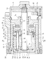
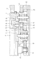
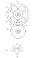
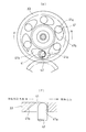
- a longitudinal sectional view showing an embodiment of an electric linear actuator according to the present invention Sectional drawing which expands and shows a part of FIG. Sectional view along line III-III in FIG. Sectional drawing which expands and shows the gear reduction mechanism part of FIG.
- (A) is a cross-sectional view taken along the line VV in FIG. 4, and (b) is a cross-sectional view taken along the line bb in (a).
- (C) is a sectional view showing another example of the locking portion
- (d) is a sectional view taken along the line dd of (c).
- E) is a cross-sectional view showing another example of the locking portion
- (f) is a cross-sectional view taken along line ff in (e).
- (G) is a cross-sectional view showing another example of the locking portion
- (h) is a cross-sectional view taken along the line hh of (g).
- a longitudinal sectional view showing an embodiment of an electric disc brake device according to the present invention Sectional view showing another example of rotation / linear motion conversion mechanism
- FIG. 1 to 5 show an embodiment of an electric linear actuator A according to the present invention.
- the housing 1 has a cylindrical shape, and a base plate 3 is provided at one end thereof in a radially outward direction, and the outer surface of the base plate 3 and one end opening of the housing 1 are covered by a cover 4. It has been broken.
- An outer ring member 5 as a slide member is incorporated in the housing 1.
- the outer ring member 5 is prevented from rotating and is movable in the axial direction along the inner diameter surface of the housing 1, and a spiral protrusion 6 having a V-shaped cross section is provided on the inner diameter surface as shown in FIG. ing.
- a bearing member 7 is incorporated on one end side of the outer ring member 5 in the axial direction.
- the bearing member 7 has a disk shape, and a boss portion 7a is provided at the center thereof.
- the bearing member 7 is prevented from moving to the cover 4 side by a stopper ring 8 attached to the inner diameter surface of the housing 1.
- a pair of rolling bearings 9 is incorporated in the boss portion 7a of the bearing member 7 with an interval in the axial direction, and the rotating shaft 10 disposed on the axis of the outer ring member 5 is rotatably supported by the rolling bearing 9. Has been.
- an electric motor 11 is supported on the base plate 3, and the rotation of the rotor shaft 12 of the electric motor 11 is transmitted to the rotating shaft 10 by a gear reduction mechanism 13 incorporated in the cover 4. It has become.
- a carrier 14 that can rotate around the rotation shaft 10 is incorporated inside the outer ring member 5.
- the carrier 14 has a pair of discs 14a and 14b that are opposed in the axial direction, and a plurality of gap adjustments are made on the outer peripheral portion of one disc 14a toward the other disc 14b.
- the members 14c are provided at intervals in the circumferential direction, and the pair of disks 14a and 14b are connected to each other by tightening the screws 15 screwed into the end faces of the interval adjusting members 14c.
- the inner disk 14b positioned on the bearing member 7 side is supported by a plain bearing 16 incorporated between the disk 10 and the rotary shaft 10 so as to be rotatable and movable in the axial direction. ing.
- a shaft insertion hole 17 having a stepped hole is formed at the center of the outer disk 14a, and a slide bearing 18 fitted in the shaft insertion hole 17 is rotatably supported by the rotary shaft 10.
- a metal washer W that receives a thrust load is fitted to the rotary shaft 10 adjacent to the outer end surface of the slide bearing 18, and the washer W is secured by a retaining ring 19 attached to the shaft end of the rotary shaft 10. ing.
- the carrier 14 is provided with a plurality of roller shafts 20 supported at both ends by a pair of disks 14a and 14b at intervals in the circumferential direction.
- Each of the roller shafts 20 has a shaft end portion inserted into a shaft insertion hole 21 formed of a long hole formed in the pair of disks 14a and 14b and is supported to be movable in the radial direction. It is urged
- a planetary roller 23 is rotatably supported on each of the plurality of roller shafts 20.
- Each of the planetary rollers 23 is incorporated between the outer diameter surface of the rotating shaft 10 and the inner diameter surface of the outer ring member 5, and the rotating shaft 10 is supported by an elastic ring 22 spanned around the shaft end of the roller shaft 20.
- a plurality of spiral grooves 24 having a V-shaped cross section are formed at equal intervals in the axial direction on the outer diameter surface of the planetary roller 23, and the pitch of the spiral grooves 24 is provided in the outer ring member 5.
- the pitch of the spiral ridge 6 is the same as that of the spiral ridge 6 and meshes with the spiral ridge 6.
- a plurality of circumferential grooves may be formed at equal intervals in the axial direction at the same pitch as the spiral protrusion 6.
- a washer 25 and a thrust bearing 26 are incorporated between the inner side disk 14 b of the carrier 14 and the axial facing portion of the planetary roller 23. Further, an annular thrust plate 27 is incorporated between the carrier 14 and the bearing member 7 in the axial direction, and a thrust bearing 28 is incorporated between the thrust plate 27 and the bearing member 7.
- the opening at the other end located outside the other end opening of the housing 1 of the outer ring member 5 is closed by the attachment of the seal cover 29 to prevent foreign matter from entering the inside.
- one end of the bellows 30 is connected to the other end opening of the housing 1, and the other end of the bellows 30 is connected to the other end of the outer ring member 5, so that foreign matter can enter the housing 1 by the bellows 30. Intrusion is prevented.
- the gear reduction mechanism 13 the rotation of the input gear 31 attached to the rotor shaft 12 of the electric motor 11 sequentially decelerated by the primary reduction gear train G 1 to tertiary reduction gear train G 3 Is transmitted to the output gear 32 attached to the shaft end of the rotating shaft 10 to rotate the rotating shaft 10, and the rotor shaft 12 of the electric motor 11 can be locked and unlocked by the gear reduction mechanism 13.
- a locking mechanism 40 is provided.
- the locking mechanism 40 is provided at regular intervals a plurality of locking holes 41 on the same circle on the side surface of the output side of the intermediate gear 33 in the secondary reduction gear train G 2, the plurality The lock pin 42 provided so as to be able to advance and retreat with respect to one point on the pitch circle of the locking hole 41 is advanced and retracted by a linear solenoid 43 as a pin driving actuator, and by engaging the lock pin 42 with the locking hole 41, The intermediate gear 33 is locked.
- the solenoid 43 is protected by a protective cover 44.
- the protective cover 44 is supported by the base plate 3 and disposed between the housing 1 and the electric motor 11, and a pin hole 46 for slidably supporting the lock pin 42 is formed in the front plate 45 of the protective cover 44. .
- FIG. 9 shows an electric disc brake device B that employs the electric linear actuator A.
- a caliper body portion 50 is provided integrally with the other end portion of the housing 1 in the electric linear actuator A, and a brake having a part of the outer peripheral portion disposed in the caliper body portion 50.
- a fixed brake pad 52 and a movable brake pad 53 are provided on both sides of the disk 51, and the movable brake pad 53 is connected and integrated with the other end of the outer ring member 5.
- the movable brake pad 53 When parking, the movable brake pad 53 is pressed against the brake disc 51 as described above, and the linear solenoid 43 is operated in a state where the braking force required for parking is applied to the brake disc 51, and the lock pin 42 is moved to the intermediate gear. Advance toward the side of 33.
- the lock pin 42 moves forward, if there is a phase shift between the lock pin 42 and the locking hole 41, the locking pin 42 cannot be engaged with the locking hole 41.
- the intermediate gear 33 is rotated in the braking direction (the direction indicated by the arrow in FIG.
- the intermediate gear 33 is rotated to the opposite position, and the lock pin 42 is engaged with the locking hole 41.
- a locking hole 41 in the intermediate gear close to the input gear 31 In order to prevent the damage more effectively, it is preferable to provide a locking hole 41 in the intermediate gear close to the input gear 31.
- the installation position of the lock pin 42 is determined in accordance with the formation position of the locking hole 41.
- the linear solenoid 43 is disposed between the housing 1 and the electric motor 11, the weight balance is not lost, and it is possible to prevent the braking from becoming unstable. Since the linear solenoid 43 is protected by 1, a simple cover can be used as the protective cover 44.
- the locking hole 41 is the locking portion, but the locking portion is not limited to this.
- 6 to 8 show other examples of the locking portion. 6 (c) and 6 (d), a plurality of projecting portions 60 extending in the radial direction of the intermediate gear 33 are provided in a radial arrangement, and a radial groove 61 formed between adjacent projecting portions 60 is used as a locking portion. Yes.
- the engaging hole 41 is used as an engaging part, and the engaging hole 41 is engaged with the lock pin 42 at one end in the circumferential direction.
- a tapered surface 41b is provided.
- the intermediate gear 33 can be smoothly rotated in the braking direction, and the prescribed pressing force required for parking on the brake disc 51 is ensured. Can be reliably loaded.
- the radial groove 61 is used as a locking part, and the radial groove 61 is engaged with the lock pin 42 on one side in the circumferential direction.
- a lock surface 61 a that prevents the intermediate gear 33 from rotating in the braking release direction is provided, and a taper that moves the lock pin 42 in the direction of exiting the radial groove 61 by the rotation of the intermediate gear 33 in the braking direction on the other side.
- a surface 61b is provided.
- the intermediate gear 33 can be smoothly rotated in the braking direction as in the case shown in FIG. It is possible to reliably load the disc 51 with a predetermined pressing force necessary for parking.
- a planetary roller is provided between the outer diameter surface of the rotary shaft 10 and the inner diameter surface of the housing 1 as a rotation / linear motion conversion mechanism for converting the rotary motion of the rotary shaft 10 into a linear motion.
- 23 is shown, and a spiral groove 24 or a circumferential groove that meshes with the spiral protrusion 6 provided on the inner diameter surface of the outer ring member 5 is formed on the outer diameter surface of the planetary roller 23.
- the conversion mechanism is not limited to this.
- FIG. 10 shows another example of the rotation / linear motion conversion mechanism.
- a spiral protrusion 70 is provided on the outer diameter surface of the rotating shaft 10
- each of the plurality of planetary rollers 23 incorporated between the outer diameter surface of the rotating shaft 10 and the inner diameter surface of the housing 1 is provided on each outer diameter surface.
- a plurality of circumferential grooves 71 are formed at the same pitch as the spiral protrusions 70, and the planetary roller 23 is rotated and revolved by the rotation of the rotating shaft 10 by the engagement of the spiral protrusions 70 and the circumferential grooves 71, The planetary roller 23 is moved in the axial direction. In this case, the axial force of the planetary roller 23 is transmitted to the driven member via the thrust bearing 72.
Landscapes
- Engineering & Computer Science (AREA)
- General Engineering & Computer Science (AREA)
- Mechanical Engineering (AREA)
- Transportation (AREA)
- Braking Arrangements (AREA)
- Transmission Devices (AREA)
Abstract
Description
B 電動式ディスクブレーキ装置
1 ハウジング
5 外輪部材
6 螺旋突条
10 回転軸
11 電動モータ
12 ロータ軸
13 ギヤ減速機構
14 キャリア
23 遊星ローラ
24 螺旋溝
31 入力ギヤ
32 出力ギヤ
33 中間ギヤ
40 ロック機構
41 係止孔(係止部)
41a ロック面
41b テーパ面
42 ロックピン
43 リニアソレノイド(ピン駆動用アクチュエータ)
51 ブレーキディスク
53 可動ブレーキパッド
60 突出部
61 径方向溝部(係止部)
61a ロック面
61b テーパ面
70 螺旋突条
71 円周溝
Claims (13)
- 電動モータと、その電動モータのロータ軸の回転を減速して出力するギヤ減速機構と、そのギヤ減速機構の出力ギヤの軸心に沿って軸方向に移動可能なスライド部材と、前記出力ギヤの回転運動を直線運動に変換して前記スライド部材に伝達する回転・直動変換機構と、前記電動モータのロータ軸の回転をロックおよびアンロック可能なロック機構とを有してなる電動式直動アクチュエータにおいて、
前記ロック機構が、ギヤ減速機構を形成する複数のギヤのうちの一つのギヤの側面周方向に設けられた複数の係止部と、その係止部に対して進退可能に設けられ、前進時に前記係止部に係合してギヤをロックするロックピンと、前記電動モータと前記スライド部材および回転・直動変換機構を収容するハウジング間に組み込まれてそのロックピンを進退させるピン駆動用アクチュエータとからなることを特徴とする電動式直動アクチュエータ。 - 前記係止部が、前記出力ギヤを除く他のギヤの側面に設けられた請求項1に記載の電動式直動アクチュエータ。
- 前記係止部が、前記電動モータのロータ軸に取付けられた入力ギヤと近接する部位のギヤに設けられた請求項2に記載の電動式直動アクチュエータ。
- 前記係止部が、前記電動モータのロータ軸に取付けられた入力ギヤと出力ギヤ間の中間ギヤに設けられた請求項2に記載の電動式直動アクチュエータ。
- 前記係止部が、貫通状の係止孔からなる請求項1乃至4のいずれかの項に記載の電動式直動アクチュエータ。
- 前記係止孔の周方向の一端部にロックピンと係合してギヤがスライド部材を後退動させる方向に回転するのを防止するロック面を設け、かつ、他端部にギヤがスライド部材を前進動させる方向に回転する場合にロックピンを係止孔から抜け出る方向に移動させるテーパ面を設けた請求項5に記載の電動式直動アクチュエータ。
- 前記係止部が、ギヤの側面に形成された放射状配置の径方向溝部からなる請求項1乃至4のいずれかの項に記載の電動式直動アクチュエータ。
- 前記径方向溝部の周方向の一側にロックピンと係合してギヤがスライド部材を後退動させる方向に回転するのを防止するロック面を設け、かつ、他側にギヤがスライド部材を前進動させる方向に回転する場合にロックピンを後退動させるテーパ面を設けた請求項7に記載の電動式直動アクチュエータ。
- 前記ピン駆動用アクチュエータが、リニアソレノイドからなる請求項1乃至8のいずれかの項に記載の電動式直動アクチュエータ。
- 前記ロック機構が、前記ロックピンをギヤに向けて付勢する弾性部材を有してなる請求項1乃至8のいずれかの項に記載の電動式直動アクチュエータ。
- 前記回転・直動変換機構が、ギヤ減速機構の出力ギヤを支持する回転軸と、その回転軸と同軸上に配置されてハウジングによりスライド自在に支持された外輪部材と、前記回転軸を中心にして回転自在に支持されたキャリアと、そのキャリアにより回転自在に支持されて回転軸の外径面と外輪部材の内径面間に組み込まれた遊星ローラとを有し、前記遊星ローラの外径面に前記外輪部材の内径面に設けられた螺旋突条に噛合する螺旋溝または円周溝を形成し、前記回転軸の回転により、その回転軸との接触摩擦により遊星ローラを回転させてスライド部材としての外輪部材を軸方向に移動させるようにした構成からなる請求項1乃至10のいずれかの項に記載の電動式直動アクチュエータ。
- 前記回転・直動変換機構が、ギヤ減速機構の出力ギヤを支持する回転軸と、その回転軸と同軸上に配置された円筒状のハウジングと、そのハウジングの内径面と前記回転軸の外径面間に組み込まれた複数の遊星ローラとを有し、前記遊星ローラの外径面に前記回転軸の外径面に設けられた螺旋突条に噛合する円周溝を、螺旋突条と同一のピッチで形成して、その円周溝と螺旋突条の係合により、前記回転軸の回転運動をスライド部材としての遊星ローラの直線運動に変換するようにした構成からなる請求項1乃至10のいずれかの項に記載の電動式直動アクチュエータ。
- 電動式直動アクチュエータによりブレーキパッドを直線駆動し、そのブレーキパッドでブレーキディスクを押圧して、そのブレーキディスクに制動力を付与するようにした電動式ディスクブレーキ装置において、
前記電動式直動アクチュエータが請求項1乃至12のいずれかの項に記載の電動式直動アクチュエータからなり、その電動式直動アクチュエータのスライド部材に前記ブレーキパッドを連結したことを特徴とする電動式ディスクブレーキ装置。
Priority Applications (3)
| Application Number | Priority Date | Filing Date | Title |
|---|---|---|---|
| DE112011103541.1T DE112011103541B4 (de) | 2010-10-20 | 2011-10-17 | Elektrischer Linearbewegungsaktuator und elektrisches Scheibenbremssystem |
| US13/877,456 US9182021B2 (en) | 2010-10-20 | 2011-10-17 | Electric linear motion actuator and electric disk brake system |
| CN201180050332.5A CN103154556B (zh) | 2010-10-20 | 2011-10-17 | 电动式直动驱动器以及电动式盘形制动装置 |
Applications Claiming Priority (2)
| Application Number | Priority Date | Filing Date | Title |
|---|---|---|---|
| JP2010-235613 | 2010-10-20 | ||
| JP2010235613A JP5829394B2 (ja) | 2010-10-20 | 2010-10-20 | 電動式直動アクチュエータおよび電動式ディスクブレーキ装置 |
Publications (1)
| Publication Number | Publication Date |
|---|---|
| WO2012053469A1 true WO2012053469A1 (ja) | 2012-04-26 |
Family
ID=45975181
Family Applications (1)
| Application Number | Title | Priority Date | Filing Date |
|---|---|---|---|
| PCT/JP2011/073803 Ceased WO2012053469A1 (ja) | 2010-10-20 | 2011-10-17 | 電動式直動アクチュエータおよび電動式ディスクブレーキ装置 |
Country Status (5)
| Country | Link |
|---|---|
| US (1) | US9182021B2 (ja) |
| JP (1) | JP5829394B2 (ja) |
| CN (1) | CN103154556B (ja) |
| DE (1) | DE112011103541B4 (ja) |
| WO (1) | WO2012053469A1 (ja) |
Cited By (5)
| Publication number | Priority date | Publication date | Assignee | Title |
|---|---|---|---|---|
| JP2013160359A (ja) * | 2012-02-08 | 2013-08-19 | Ntn Corp | 電動式直動アクチュエータおよび電動式ブレーキ装置 |
| WO2016080186A1 (ja) * | 2014-11-19 | 2016-05-26 | Ntn株式会社 | 電動式直動アクチュエータおよび電動式ブレーキ装置 |
| JP2016118264A (ja) * | 2014-12-22 | 2016-06-30 | Ntn株式会社 | 電動式直動アクチュエータおよび電動式ブレーキ装置 |
| WO2017170291A1 (ja) * | 2016-03-30 | 2017-10-05 | Ntn株式会社 | 電動アクチュエータ |
| WO2022174858A1 (de) * | 2021-02-16 | 2022-08-25 | Schaeffler Technologies AG & Co. KG | Arretierungseinheit für aktuator einer fahrzeugbremse |
Families Citing this family (41)
| Publication number | Priority date | Publication date | Assignee | Title |
|---|---|---|---|---|
| JP5596575B2 (ja) * | 2011-01-21 | 2014-09-24 | Ntn株式会社 | 電動式直動アクチュエータおよび電動式ディスクブレーキ装置 |
| JP5937334B2 (ja) * | 2011-11-02 | 2016-06-22 | Ntn株式会社 | 電動式直動アクチュエータ |
| JP6118132B2 (ja) * | 2012-09-11 | 2017-04-19 | 株式会社ミツバ | リニアアクチュエータ |
| JP6076023B2 (ja) | 2012-10-12 | 2017-02-08 | Ntn株式会社 | 電動パーキングブレーキ装置及び電動ブレーキ装置 |
| JP6091841B2 (ja) * | 2012-10-25 | 2017-03-08 | Ntn株式会社 | パーキング機能付き電動ブレーキアクチュエータ |
| JP2014132261A (ja) * | 2012-12-03 | 2014-07-17 | Ntn Corp | 電動パーキングブレーキ装置 |
| US8807312B2 (en) | 2012-12-19 | 2014-08-19 | Deere & Company | Hydraulic actuating pin system |
| JP6190146B2 (ja) * | 2013-04-22 | 2017-08-30 | Ntn株式会社 | 電動式直動アクチュエータおよび電動式ブレーキ装置 |
| JP2014226005A (ja) * | 2013-05-17 | 2014-12-04 | Ntn株式会社 | 電動式直動アクチュエータおよび電動式ブレーキ装置 |
| JP6335443B2 (ja) | 2013-06-13 | 2018-05-30 | Ntn株式会社 | 電動式ブレーキ装置 |
| JP6223754B2 (ja) * | 2013-09-06 | 2017-11-01 | Ntn株式会社 | 電動式直動アクチュエータおよび電動式ブレーキ装置 |
| JP6289855B2 (ja) * | 2013-10-10 | 2018-03-07 | Ntn株式会社 | パーキング機能付き電動ブレーキ装置 |
| JP6267968B2 (ja) * | 2014-01-21 | 2018-01-24 | Ntn株式会社 | 電動ブレーキ装置 |
| US10316915B2 (en) * | 2014-04-01 | 2019-06-11 | Freni Brembo S.P.A. | Brake gear motor group |
| DE102014212863B4 (de) * | 2014-07-02 | 2020-08-20 | Stabilus Gmbh | Klappensteuerung |
| CN104455401B (zh) * | 2014-09-30 | 2017-01-18 | 长城汽车股份有限公司 | 驻车锁止装置 |
| US9683617B2 (en) * | 2014-12-30 | 2017-06-20 | Johnson Electric S.A. | Self-locking mechanism |
| CN104528602B (zh) * | 2014-12-30 | 2017-06-20 | 江苏华澳橡胶机械有限公司 | 升降装置 |
| JP6468851B2 (ja) * | 2015-01-15 | 2019-02-13 | Ntn株式会社 | 電動式直動アクチュエータおよび電動式ブレーキ装置 |
| CN105987108B (zh) * | 2015-01-30 | 2019-07-09 | 德昌电机(深圳)有限公司 | 电动驻车系统的执行器及其自锁机构 |
| US9592813B2 (en) | 2015-06-25 | 2017-03-14 | Akebono Brake Industry Co., Ltd | Actuator assembly for a parking brake system |
| JP6585419B2 (ja) * | 2015-08-10 | 2019-10-02 | マブチモーター株式会社 | 出力軸、減速機および減速機付モータ |
| JP6552910B2 (ja) * | 2015-08-11 | 2019-07-31 | Ntn株式会社 | 電動ブレーキシステム |
| DE102016221189B4 (de) | 2015-10-30 | 2020-01-09 | Continental Teves Ag & Co. Ohg | Radbremsaktuatormodul für eine elektrisch kombiniert betätigbare Kraftfahrzeugbremse |
| WO2017152928A1 (en) * | 2016-03-07 | 2017-09-14 | Abb Schweiz Ag | A brake for an actuator of an industrial robot |
| JP6700134B2 (ja) * | 2016-07-21 | 2020-05-27 | Ntn株式会社 | 電動アクチュエータ |
| JP6610477B2 (ja) * | 2016-03-30 | 2019-11-27 | 日本電産株式会社 | 回転アクチュエータおよびロボット |
| JP6679380B2 (ja) * | 2016-03-30 | 2020-04-15 | Ntn株式会社 | 電動アクチュエータ |
| JP6475187B2 (ja) | 2016-04-28 | 2019-02-27 | トヨタ自動車株式会社 | 駆動装置 |
| CN107786037B (zh) * | 2016-08-26 | 2024-03-22 | 日本电产三协电子(东莞)有限公司 | 马达装置 |
| CN106224415A (zh) * | 2016-09-08 | 2016-12-14 | 上海六辔机电科技有限公司 | 一种轨道车辆电机驱动摩擦制动装置 |
| ES2850203T3 (es) * | 2017-06-08 | 2021-08-26 | Ims Gear Se & Co Kgaa | Disposición de engranaje de ruedas planetarias, en particular para un freno de servicio electromecánico o un freno de estacionamiento electromecánico para un vehículo de motor |
| DE102017215291A1 (de) * | 2017-08-31 | 2019-02-28 | Knorr-Bremse Systeme für Schienenfahrzeuge GmbH | Elektro-mechanischer Bremsaktuator mit Nachspeisung für eine Feststellbremse eines Schienenfahrzeugs |
| EP3477141A1 (en) | 2017-10-18 | 2019-05-01 | Molon Motor and Coil Corporation | Mechanical brake for an electric motor |
| DE102018222125B3 (de) | 2018-12-18 | 2020-04-02 | Continental Teves Ag & Co. Ohg | Trommelbremse |
| JP7308070B2 (ja) * | 2019-04-26 | 2023-07-13 | ナブテスコ株式会社 | ブレーキ装置およびブレーキ制御システム |
| ES2947868T3 (es) * | 2019-05-13 | 2023-08-23 | Brembo Spa | Pinza de freno para freno de disco |
| WO2021078403A1 (de) * | 2019-10-22 | 2021-04-29 | Sew-Eurodrive Gmbh & Co. Kg | Bremsanordnung und elektromotor mit einer bremsanordnung |
| WO2021144966A1 (ja) * | 2020-01-17 | 2021-07-22 | ヤマハ発動機株式会社 | 回転規制機構用回転体及びアクチュエータ |
| WO2022222135A1 (en) * | 2021-04-23 | 2022-10-27 | Techtronic Cordless Gp | Force amplified fastener for power tool implements |
| JP7760951B2 (ja) * | 2022-03-30 | 2025-10-28 | 株式会社デンソー | 車両用ブレーキ装置 |
Citations (4)
| Publication number | Priority date | Publication date | Assignee | Title |
|---|---|---|---|---|
| JPS58110343A (ja) * | 1981-12-22 | 1983-06-30 | Fuji Heavy Ind Ltd | 車両用自動パ−キングロツク装置 |
| JP2003336672A (ja) * | 2002-05-20 | 2003-11-28 | Nissin Kogyo Co Ltd | 電気式ディスクブレーキ |
| JP2008275053A (ja) * | 2007-04-27 | 2008-11-13 | Hitachi Ltd | 電動ディスクブレーキおよびロック装置 |
| JP2010090959A (ja) * | 2008-10-07 | 2010-04-22 | Ntn Corp | 電動式直動アクチュエータおよび電動式ブレーキ装置 |
Family Cites Families (7)
| Publication number | Priority date | Publication date | Assignee | Title |
|---|---|---|---|---|
| US5310026A (en) * | 1992-10-19 | 1994-05-10 | General Motors Corporation | Electric drum brake |
| US6305506B1 (en) * | 1996-10-03 | 2001-10-23 | Toyota Jidosha Kabushiki Kaisha | Braking system including motor-driven disc brake equipped with self-servo mechanism |
| DE19804454A1 (de) | 1997-11-21 | 1999-05-27 | Itt Mfg Enterprises Inc | Elektromechanisch betätigbare Scheibenbremse |
| JP4556176B2 (ja) | 2004-12-28 | 2010-10-06 | 日立オートモティブシステムズ株式会社 | 電動ブレーキ装置 |
| JP5243018B2 (ja) * | 2007-12-27 | 2013-07-24 | Ntn株式会社 | 電動リニアアクチュエータ |
| JP5057164B2 (ja) * | 2008-08-29 | 2012-10-24 | 日立オートモティブシステムズ株式会社 | 電動ディスクブレーキ |
| JP5257764B2 (ja) | 2008-09-11 | 2013-08-07 | Ntn株式会社 | 電動式直動アクチュエータおよび電動式ブレーキ装置 |
-
2010
- 2010-10-20 JP JP2010235613A patent/JP5829394B2/ja not_active Expired - Fee Related
-
2011
- 2011-10-17 CN CN201180050332.5A patent/CN103154556B/zh not_active Expired - Fee Related
- 2011-10-17 DE DE112011103541.1T patent/DE112011103541B4/de not_active Expired - Fee Related
- 2011-10-17 WO PCT/JP2011/073803 patent/WO2012053469A1/ja not_active Ceased
- 2011-10-17 US US13/877,456 patent/US9182021B2/en active Active
Patent Citations (4)
| Publication number | Priority date | Publication date | Assignee | Title |
|---|---|---|---|---|
| JPS58110343A (ja) * | 1981-12-22 | 1983-06-30 | Fuji Heavy Ind Ltd | 車両用自動パ−キングロツク装置 |
| JP2003336672A (ja) * | 2002-05-20 | 2003-11-28 | Nissin Kogyo Co Ltd | 電気式ディスクブレーキ |
| JP2008275053A (ja) * | 2007-04-27 | 2008-11-13 | Hitachi Ltd | 電動ディスクブレーキおよびロック装置 |
| JP2010090959A (ja) * | 2008-10-07 | 2010-04-22 | Ntn Corp | 電動式直動アクチュエータおよび電動式ブレーキ装置 |
Cited By (8)
| Publication number | Priority date | Publication date | Assignee | Title |
|---|---|---|---|---|
| JP2013160359A (ja) * | 2012-02-08 | 2013-08-19 | Ntn Corp | 電動式直動アクチュエータおよび電動式ブレーキ装置 |
| WO2016080186A1 (ja) * | 2014-11-19 | 2016-05-26 | Ntn株式会社 | 電動式直動アクチュエータおよび電動式ブレーキ装置 |
| CN107002840A (zh) * | 2014-11-19 | 2017-08-01 | Ntn株式会社 | 电动式直动致动器以及电动式制动装置 |
| US10508722B2 (en) | 2014-11-19 | 2019-12-17 | Ntn Corporation | Electric linear motion actuator and electromechanical brake system |
| JP2016118264A (ja) * | 2014-12-22 | 2016-06-30 | Ntn株式会社 | 電動式直動アクチュエータおよび電動式ブレーキ装置 |
| WO2017170291A1 (ja) * | 2016-03-30 | 2017-10-05 | Ntn株式会社 | 電動アクチュエータ |
| US11162565B2 (en) | 2016-03-30 | 2021-11-02 | Ntn Corporation | Electric actuator |
| WO2022174858A1 (de) * | 2021-02-16 | 2022-08-25 | Schaeffler Technologies AG & Co. KG | Arretierungseinheit für aktuator einer fahrzeugbremse |
Also Published As
| Publication number | Publication date |
|---|---|
| US20130186717A1 (en) | 2013-07-25 |
| JP5829394B2 (ja) | 2015-12-09 |
| JP2012087889A (ja) | 2012-05-10 |
| CN103154556B (zh) | 2016-04-20 |
| CN103154556A (zh) | 2013-06-12 |
| US9182021B2 (en) | 2015-11-10 |
| DE112011103541B4 (de) | 2022-02-24 |
| DE112011103541T5 (de) | 2013-08-01 |
Similar Documents
| Publication | Publication Date | Title |
|---|---|---|
| JP5829394B2 (ja) | 電動式直動アクチュエータおよび電動式ディスクブレーキ装置 | |
| EP1912313B1 (en) | Electric direct-acting actuator and electric brake device | |
| US8348023B2 (en) | Disk brake | |
| CN104653736B (zh) | 行星滚动传动机构和具有所述行星滚动传动机构的致动器 | |
| JPH0563655B2 (ja) | ||
| WO2014200052A1 (ja) | 電動式直動アクチュエータおよび電動式ブレーキ装置 | |
| WO2010041588A1 (ja) | 電動式直動アクチュエータおよび電動式ブレーキ装置 | |
| WO2009104578A1 (ja) | 電動式直動アクチュエータおよび電動式ブレーキ装置 | |
| JP2010065777A (ja) | 電動式直動アクチュエータおよび電動式ブレーキ装置 | |
| US20130168192A1 (en) | Electric linear motion actuator and electric disk brake system | |
| JP5496836B2 (ja) | 電動式直動アクチュエータおよび電動式ディスクブレーキ装置 | |
| JP2005083474A (ja) | 電動リニアアクチュエータ | |
| JP2011047448A (ja) | 電動アクチュエータ | |
| JP2013160335A (ja) | 電動式直動アクチュエータおよび電動式ブレーキ装置 | |
| JP5585865B2 (ja) | 電動式直動アクチュエータおよび電動式ブレーキ装置 | |
| JP2011074946A (ja) | ディスクブレーキ | |
| JP4697784B2 (ja) | 電動リニアアクチュエータ | |
| JP5946399B2 (ja) | 電動式ディスクブレーキ装置 | |
| JP5944674B2 (ja) | 電動式直動アクチュエータおよび電動式ブレーキ装置 | |
| JP2011075051A (ja) | ディスクブレーキ | |
| JP4959639B2 (ja) | 電動ブレーキ装置 | |
| JP5440923B2 (ja) | 電動式直動アクチュエータおよび電動式ブレーキ装置 | |
| JP2010236658A (ja) | ディスクブレーキ | |
| JP2012175772A (ja) | 電動式直動アクチュエータおよび電動式ディスクブレーキ装置 | |
| JP5474475B2 (ja) | 電動式直動アクチュエータおよび電動式ブレーキ装置 |
Legal Events
| Date | Code | Title | Description |
|---|---|---|---|
| WWE | Wipo information: entry into national phase |
Ref document number: 201180050332.5 Country of ref document: CN |
|
| 121 | Ep: the epo has been informed by wipo that ep was designated in this application |
Ref document number: 11834308 Country of ref document: EP Kind code of ref document: A1 |
|
| WWE | Wipo information: entry into national phase |
Ref document number: 13877456 Country of ref document: US |
|
| WWE | Wipo information: entry into national phase |
Ref document number: 112011103541 Country of ref document: DE Ref document number: 1120111035411 Country of ref document: DE |
|
| 122 | Ep: pct application non-entry in european phase |
Ref document number: 11834308 Country of ref document: EP Kind code of ref document: A1 |