WO2012053430A1 - 蒸着装置及び蒸着方法 - Google Patents
蒸着装置及び蒸着方法 Download PDFInfo
- Publication number
- WO2012053430A1 WO2012053430A1 PCT/JP2011/073619 JP2011073619W WO2012053430A1 WO 2012053430 A1 WO2012053430 A1 WO 2012053430A1 JP 2011073619 W JP2011073619 W JP 2011073619W WO 2012053430 A1 WO2012053430 A1 WO 2012053430A1
- Authority
- WO
- WIPO (PCT)
- Prior art keywords
- substrate
- mask
- region
- deposition
- vapor deposition
- Prior art date
- Legal status (The legal status is an assumption and is not a legal conclusion. Google has not performed a legal analysis and makes no representation as to the accuracy of the status listed.)
- Ceased
Links
Images







Classifications
-
- C—CHEMISTRY; METALLURGY
- C23—COATING METALLIC MATERIAL; COATING MATERIAL WITH METALLIC MATERIAL; CHEMICAL SURFACE TREATMENT; DIFFUSION TREATMENT OF METALLIC MATERIAL; COATING BY VACUUM EVAPORATION, BY SPUTTERING, BY ION IMPLANTATION OR BY CHEMICAL VAPOUR DEPOSITION, IN GENERAL; INHIBITING CORROSION OF METALLIC MATERIAL OR INCRUSTATION IN GENERAL
- C23C—COATING METALLIC MATERIAL; COATING MATERIAL WITH METALLIC MATERIAL; SURFACE TREATMENT OF METALLIC MATERIAL BY DIFFUSION INTO THE SURFACE, BY CHEMICAL CONVERSION OR SUBSTITUTION; COATING BY VACUUM EVAPORATION, BY SPUTTERING, BY ION IMPLANTATION OR BY CHEMICAL VAPOUR DEPOSITION, IN GENERAL
- C23C14/00—Coating by vacuum evaporation, by sputtering or by ion implantation of the coating forming material
- C23C14/22—Coating by vacuum evaporation, by sputtering or by ion implantation of the coating forming material characterised by the process of coating
- C23C14/56—Apparatus specially adapted for continuous coating; Arrangements for maintaining the vacuum, e.g. vacuum locks
-
- C—CHEMISTRY; METALLURGY
- C23—COATING METALLIC MATERIAL; COATING MATERIAL WITH METALLIC MATERIAL; CHEMICAL SURFACE TREATMENT; DIFFUSION TREATMENT OF METALLIC MATERIAL; COATING BY VACUUM EVAPORATION, BY SPUTTERING, BY ION IMPLANTATION OR BY CHEMICAL VAPOUR DEPOSITION, IN GENERAL; INHIBITING CORROSION OF METALLIC MATERIAL OR INCRUSTATION IN GENERAL
- C23C—COATING METALLIC MATERIAL; COATING MATERIAL WITH METALLIC MATERIAL; SURFACE TREATMENT OF METALLIC MATERIAL BY DIFFUSION INTO THE SURFACE, BY CHEMICAL CONVERSION OR SUBSTITUTION; COATING BY VACUUM EVAPORATION, BY SPUTTERING, BY ION IMPLANTATION OR BY CHEMICAL VAPOUR DEPOSITION, IN GENERAL
- C23C14/00—Coating by vacuum evaporation, by sputtering or by ion implantation of the coating forming material
- C23C14/04—Coating on selected surface areas, e.g. using masks
- C23C14/042—Coating on selected surface areas, e.g. using masks using masks
Definitions
- the present invention relates to a vapor deposition technique for producing, for example, an organic EL display or an organic EL lighting device.
- FIG. 13 is a schematic configuration diagram showing a conventional vapor deposition apparatus.
- the substrate 110 is carried into the vacuum chamber 102 from the vacuum transfer unit 104, the substrate 110 and the mask mechanism 111 are aligned by the alignment mechanism 105, and then Then, the evaporation source 109 is moved in the horizontal direction to perform vapor deposition on the substrate 110.
- the vapor deposition rate must be precisely controlled, so that the vapor deposition rate is reduced only during the waiting time between processes such as alignment. Control cannot be performed and vapor must continue to be released at a constant deposition rate.
- the prior art has a problem that the evaporation material is wasted.
- a reduction in tact time has been demanded, so that there has been a tendency that the deposition rate tends to be large, and thus there is a problem that the waste of the evaporation material increases.
- the present invention has been made to solve the above-described problems of the conventional technique, and an object of the present invention is to provide a technique capable of reducing the waste of the evaporation material due to the waiting time during vapor deposition. There is.
- the present invention provides a vacuum chamber in which a plurality of substrates can be carried in or out, a unit provided in the vacuum chamber, the loaded substrate and a mask are combined, and vapor deposition is completed.
- a standby area that is provided in the vacuum chamber and waits for the combined substrate and the mask, and the combined substrate and mask are deposited between the substrate loading / unloading area and the standby area.
- a first transport mechanism that transports between the start position and the deposition region, and the plurality of combined substrates and masks between the substrate carry-in / out region and the deposition start position, and the deposition start Comprising a plurality of second transport mechanism for transporting each between the location and the waiting area, the standby area is an evaporation apparatus which is provided at a position not overlapping with respect to the first conveying mechanism.
- the present invention is also effective when an alignment region for aligning the loaded substrate and the mask is provided in the substrate carry-in / out region.
- the present invention is also effective when the standby area is provided below the first transport mechanism.
- the present invention is also effective when the substrate carry-in / carry-out region is provided above the first transport mechanism.
- the present invention is also effective when cooling means for cooling the substrate is provided in the standby area.
- the first transport mechanism has a plurality of rollers configured to support the substrate and the mask and transport in the horizontal direction
- the second transport mechanism includes the first transport mechanism. It is also effective when it has a plurality of pin-like substrate lifting members provided between a plurality of rollers of the transport mechanism and configured to support the substrate and the mask and transport in the vertical direction.
- the present invention is also effective when the rollers of the first transport mechanism are provided so as to be extendable in the horizontal direction on the inner wall portions on both sides of the vacuum chamber.
- the present invention is also effective when the substrate lifting member of the second transport mechanism has a support portion extending in the horizontal direction, and the support portion is configured to rotate by a predetermined angle in the horizontal direction. is there.
- the present invention is a vapor deposition method using any one of the above-described vapor deposition apparatuses, and in the substrate carry-in / carry-out region of the vacuum vessel, the first substrate carried into the vacuum vessel is used as a first mask. The step of combining, the combined first substrate and the first mask are transferred to the vapor deposition region by the first transfer mechanism, and the first substrate is passed through the first mask.
- the step of performing vapor deposition in the substrate carry-in / out region, after the second substrate and the second mask carried in the vacuum chamber are combined, the step of placing in the standby region, and the vapor deposition is completed.
- the first substrate and the first mask are transferred to the substrate carry-in / out region by the first transfer mechanism, and the first substrate is separated from the first mask and transferred out of the vacuum chamber.
- a step, the second substrate and the second substrate A step of carrying out vapor deposition on the second substrate and the second mask by conveying a disc to the vapor deposition region by the first conveyance mechanism, and separating the first substrate from the first mask
- a step of carrying out of the vacuum chamber and a step of transporting the first substrate and the first mask to the deposition region and performing deposition on the first substrate through the first mask.
- the second substrate and the second mask that have been deposited are transported to the substrate carry-in / out region by the first transport mechanism, the second substrate is separated from the second mask, and the second mask is separated.
- a substrate carry-in / out region, a standby region, and a vapor deposition region are provided in the vacuum chamber, and the combined substrate and mask are subjected to a vapor deposition start position between the substrate carry-in / out region and the standby region, While being transported by the first transport mechanism between the deposition region and the plurality of combined substrates and masks, between the substrate carry-in / out region and the deposition start position, and between the deposition start position and the standby region.
- the standby area is provided at a position that does not overlap with the first transport mechanism, for example, in the vertical direction, among the plurality of combined substrates and masks While the predetermined substrate and the mask are transported to the standby area by the predetermined second transport mechanism and made to stand by, the other substrate and the mask are moved to the deposition start position by the other second transport mechanism. Feeding to, it is possible to perform deposition is transported to the deposition region by the first transfer mechanism. And the board
- the waste of the evaporation material can be reduced by minimizing the waiting time for transporting the substrate as compared with the prior art. Further, in the present invention, since the order of the substrate and the mask can be changed in the vacuum chamber, the waiting time for the film formation can be minimized and the waste of the evaporation material can be reduced. In the present invention, when a cooling means for cooling the mask is provided in the standby area, it is possible to suppress an increase in the temperature of the mask, so that the mask is prevented from expanding and more precise mask deposition is performed. Can do.
- the deposition when an alignment region for aligning the loaded substrate and the mask is provided in the substrate loading / unloading region, the deposition can be performed while the substrate and the mask are aligned.
- the tact time can be shortened, and the waste of the evaporation material can be further reduced.
- the first transport mechanism includes a plurality of rollers configured to support the substrate and the mask and transport in the horizontal direction
- the second transport mechanism includes the plurality of rollers of the first transport mechanism.
- the rollers of the first transport mechanism are arranged on both sides of the vacuum chamber.
- the inner wall portion is provided to be extendable in the horizontal direction, or the substrate lifting member of the second transport mechanism has a support portion extending in the horizontal direction, and the support portion rotates by a predetermined angle in the horizontal direction.
- the combined substrate and mask are transferred from the first transfer mechanism to the second transfer mechanism without using a complicated substrate transfer mechanism such as a robot, or the second transfer mechanism is used. First from the transport mechanism It becomes possible to perform an operation to pass to the feed mechanism smoothly.
- the present invention for example, in an apparatus for manufacturing an organic EL element, it is possible to reduce the waste of the evaporation material due to the waiting time during vapor deposition.
- FIG. 2A Explanatory drawing which shows typically embodiment of the vapor deposition apparatus which concerns on this invention
- FIG. 2A is a front view
- FIG. 2B is a side view
- FIG. 2C is a plan view showing configurations of a substrate transfer mechanism and a substrate lifting mechanism according to the embodiment.
- FIG. 6A is a front view
- FIG. 6B is a side view
- FIG. 6C is a plan view.
- FIG. 7A is a front view
- FIG. 7B is a side view
- FIG. 7C is a plan view.
- FIG. 8A is a front view
- FIG. 8B is a side view
- FIG. 8C is a plan view, illustrating the operation of the embodiment (No. 3).
- FIG. 9A is a front view
- FIG. 9B is a side view
- FIG. 9C is a plan view, illustrating the operation of the embodiment (No. 4).
- FIG. 10A is a front view
- FIG. 10B is a side view
- FIG. 10C is a plan view, illustrating the operation of the embodiment (No. 5).
- FIG. 11A is a front view
- FIG. 11B is a side view
- FIG. 11A is a front view
- FIG. 11B is a side view
- FIG. 11A is a front view
- FIG. 11B is a side view
- FIG. 11C is a plan view, illustrating the operation of the embodiment (No. 6). It is explanatory drawing (the 7) which shows operation
- FIG.1 (a) is explanatory drawing which shows typically embodiment of the vapor deposition apparatus based on this invention
- FIG.1 (b) is the schematic which shows the structure inside the vapor deposition apparatus.
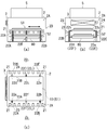
- 2A to 2C show the configurations of the substrate transport mechanism and the substrate lifting mechanism of the present embodiment.
- FIG. 2A is a front view
- FIG. 2B is a side view
- FIG. (C) is a plan view.
- the vapor deposition apparatus 1 of the present embodiment has a vacuum chamber 2 connected to a vacuum exhaust system (not shown).
- the vacuum chamber 2 includes an alignment chamber 2A and a vapor deposition chamber 2B disposed on the side of the alignment chamber 2A.
- a vacuum transfer unit is provided via a gate valve 3 provided on the upper portion of the alignment chamber 2A. 4 is connected. And it is comprised so that the board
- the present invention can be applied to various substrates such as a glass substrate as the substrate 10.
- An alignment mechanism 5 is provided on the upper surface portion of the alignment chamber 2 ⁇ / b> A of the vacuum chamber 2.
- the alignment mechanism 5 includes an alignment between the substrate 10 and the mask mechanism (mask) 11 in the substrate carry-in / out region 6 in the upper portion of the alignment chamber 2A in the vacuum chamber 2, and the combination of the substrate 10 and the mask mechanism 11.
- the substrate 10 is separated from the mask mechanism 11 and has a mechanism portion (not shown) that operates in the alignment chamber 2A.
- the alignment region 6a indicated by the alternate long and short dash line in FIGS. Each operation is configured to be performed.
- the mask mechanism 11 of the present embodiment is configured by assembling a mask on a frame-shaped pallet (details are not shown), and is configured to fix the substrate 10 to the mask mechanism 11 by a magnet 12. Has been. A specific configuration of the alignment mechanism 5 will be described later.
- first masked substrate. 51 and the other is called“ second masked substrate 52 ”.
- a substrate transport mechanism 21 is provided below the alignment region 6a in the alignment chamber 2A.
- the substrate transport mechanism 21 transports the substrate 10 in the horizontal direction by a plurality of rollers.
- the substrate transport mechanism 21 is provided on the opposite side of the vacuum chamber 2 from the substrate carry-in side, for example. It arrange
- a vapor deposition area 7 for forming a vapor deposition film on the substrate 10 is provided in the vapor deposition chamber 2B.
- the alignment chamber 2A and the vapor deposition chamber 2B are partitioned by a wall portion 2C, and the first and second masked substrates 51, through the passage port 2D provided in the wall portion 2C, 52 is configured to perform delivery.
- a gate valve can also be provided at the passage 2D.
- an evaporation source 9 is fixed at a position near the wall 2C in the vapor deposition chamber 2B, and the first and second masked substrates 51 and 52 are placed on the evaporation source 9. As a result, the deposited film is formed on the substrate 10.
- a standby region 8 is provided below the substrate transport mechanism 21 in the alignment chamber 2A at a position that does not overlap the substrate transport mechanism 21.
- a cooling plate (cooling means) 80 is provided in the standby area 8.
- the cooling plate 80 has a plate-like cooling portion having a size equivalent to that of the pallet of the mask mechanism 11 and is configured to perform cooling by circulating water, for example, inside the cooling portion.
- a substrate lifting mechanism 22 that lifts and lowers the mask mechanism 11 and the substrate 10 is provided between the standby region 8 and the alignment region 6a.
- the substrate lifting mechanism 22 includes first and second substrate lifting mechanisms 22 1 and 22 2 that operate independently from each other, and the first and second masked substrates 51 and 52. And is configured to move up and down.
- the substrate transport mechanism 21 is composed of a plurality of rollers, and each of the side walls 23 and 24 on both sides of the alignment chamber 2A is horizontally oriented. Are arranged side by side.
- each roller of the substrate transport mechanism 21 is configured to rotate clockwise or counterclockwise by a driving unit (not shown).
- Each roller of the substrate transport mechanism 21 is configured to expand and contract at a predetermined timing with respect to the side wall portions 23 and 24 on both sides of the alignment chamber 2A.
- the substrate lifting mechanism 22 includes, for example, a plurality (six in this example) of substrate lifting members 22A, 22B, 22C, 22D, 22E, and 22F extending in the vertical direction.
- the substrate elevating members 22A, 22B, 22C, 22D, 22E, and 22F are positioned outward with respect to both edges of the aligned mask mechanism 11 (upper and lower edges in FIG. 2C). It has pin-shaped main body portions arranged, and support portions 22a, 22b, 22c, 22d, 22e, and 22f for supporting the edge of the mask mechanism 11 are provided on the upper portions of the respective main body portions. ing.
- the substrate lifting mechanism 22 includes two sets, that is, the first and second substrate lifting mechanisms 22 1 and 22 2 .
- the first substrate lift mechanism 22 1 provided two substrate elevating member 22A provided on one side wall portion 23 side of the alignment chamber 2A, and 22B, on the other side wall portion 24 side of the alignment chamber 2A 1 It is comprised from the board
- two substrate elevating members 22A and 22B on one side wall portion 23 side of the alignment chamber 2A are arranged in the vicinity of both corner portions of the mask mechanism 11, and one on the other side wall portion 24 side of the alignment chamber 2A.
- the substrate elevating member 22 ⁇ / b> C is disposed at the central portion of the edge of the mask mechanism 11.
- the second substrate lifting mechanism 22 2 is provided with one substrate lifting member 22F provided on one side wall portion 23 side of the alignment chamber 2A and 2 provided on the other side wall portion 24 side of the alignment chamber 2A. It is comprised from the board
- the two substrate elevating members 22D and 22E on the other side wall 24 side of the alignment chamber 2A are arranged in the vicinity of both corners of the mask mechanism 11, and one on the side wall 23 side of the alignment chamber 2A.
- the substrate lifting member 22 ⁇ / b> F is disposed at the center of the edge of the mask mechanism 11.
- the substrate elevating members 22A to 22F are disposed so as to be positioned between the rollers of the substrate transport mechanism 21.
- the support portions 22a to 22f of the substrate elevating members 22A to 22F rotate, for example, 90 degrees horizontally from a position parallel to the line segments 11A and 11B of the edge of the mask mechanism 11 to a position vertical.
- the support portions 22a to 22f of the substrate elevating members 22A to 22F are perpendicular to the line segments 11A and 11B of the edge of the mask mechanism 11. The case of a position is shown.
- the substrate lifting member of the first substrate lifting mechanism 221. and 22A ⁇ 22C center of gravity of the support portion 22a ⁇ 22c of it is preferable that the center of gravity of the support portion 22 d ⁇ 22f of the second substrate lift mechanism 22 2 of the substrate elevating member 22D ⁇ 22F is configured to match.
- the operation of will be described. 6C to 12C, illustration of the substrate 10 and the magnet 12 is omitted as appropriate in order to facilitate understanding of the present invention.
- the first masked substrate 51 described above, the first mask mechanism (first mask) 11 1, the first substrate 10 1 is composed of a first magnet 12 1, with the second mask substrate
- Reference numeral 52 denotes a second mask mechanism (second mask) 11 2 , a first substrate 10 2 , and a first magnet 12 2 .
- the first substrate elevating member 22A ⁇ 22C of substrate lifting mechanism 22 1 is disposed so as to be positioned between the rollers of the substrate transport mechanism 21, and each substrate elevating member 22A the support portion 22a ⁇ 22c of ⁇ 22C, a first mask mechanism 11 first edge of the segment 11A, by previously arranged at a position perpendicular to the 11B, the first mask with the substrate 51, when lowering the first substrate lift mechanism 22 1, it is smoothly transferred to the substrate transfer mechanism 21 from the support portion 22a ⁇ 22c of the substrate elevating members 22A ⁇ 22C.
- the second mask mechanism 11 2 is supported by the second substrate lifting mechanism 22 2 and disposed in the alignment region 6a, and the second magnet 12 2 is disposed on the upper portion of the alignment region 6a. Waiting for the substrate 10 2 to be loaded.
- the roller of the substrate transport mechanism 21 is operated to transport the first masked substrate 51 toward the vapor deposition region 7 as shown in FIGS. 3B and 7A to 7C, initiating deposition with respect to the first substrate 10 1.
- the supporting portions 22a ⁇ 22c of the first substrate lift mechanism 22 1 of the substrate elevating members 22A ⁇ 22C, the second mask mechanism 11 second edge of the segment 11A, parallel to 11B It arranges in the position which becomes.
- FIG. 3 (c) and FIG. 8 (a) ⁇ (c) carried the second substrate 10 2 in the alignment chamber 2A, the alignment in the alignment region 6a.
- the second substrate 10 2 creates a second mask mechanism 11 2 second mask with the substrate 52 attached to the second substrate lifting mechanism 22 2
- the second masked substrate 52 is moved down from the alignment region 6 a through the deposition start position 21 a to the standby region 8, and the support portions 22 d to 22 f of the substrate elevating members 22 D to 22 F are moved from the upper surface of the cooling plate 80. by moving to a slightly lower position, and passes to the cooling plate 80 the second mask with the substrate 52 from the second substrate lift mechanism 22 2.
- the second mask mechanism 11 2 of the second masked substrate 52 is brought into close contact with the cooling plate 80, and the second substrate 10 2 is cooled.
- the rollers of the substrate transport mechanism 21 the alignment chamber 2A of both sides of the side wall 23, by reducing the length by moving each 24 side, the second mask mechanism 11 and second edge portions (portions of the segments 11A and 11B) from being in contact with the rollers of the substrate transport mechanism 21.
- the second mask mechanism 11 2 of the second masked substrate 52 is brought into close contact with the cooling plate 80, and the second substrate 10 2 is cooled.
- the first masked substrate 51 is transported from the vapor deposition chamber 2B toward the alignment chamber 2A, and the first The deposition on the surface of the substrate 10 1 is continued.
- the support portions 22a to 22c of the substrate elevating members 22A to 22C of the first substrate elevating mechanism 21 1 are set to be perpendicular to the line segments 11A and 11B at the edge of the second mask mechanism 112. It arranges in the position which becomes.
- a first mask mechanism 11 1 and separates the first and the substrate 10 1, the first alignment chamber 2A the substrate 10 1 To the vacuum transfer unit 4.
- the second substrate elevating mechanism 22 2 is lowered, thereby the second The masked substrate 52 is disposed at the vapor deposition start position 21 a on the substrate transport mechanism 21.
- the third substrate 103 is a new substrate into alignment chamber 2A, the alignment in the alignment region 6a.
- the substrate loading / unloading region 6 having the alignment region 6a, the vapor deposition region 7, and the standby region 8 are provided in the vacuum chamber 2, and the first and second masks are provided.
- the attached substrates 51 and 52 are transported by the first transport mechanism between the deposition start position 21 a between the alignment region 6 a and the standby region 8 and the deposition region 7, while having the first and second masks.
- the substrates 51 and 52 are transported by the first and second substrate lifting mechanisms 22 1 and 22 2 between the alignment region 6a and the deposition start position 21a and between the deposition start position 21a and the standby region 8, respectively.
- the standby area 8 is provided at a position that does not overlap with the substrate transport mechanism 21 in the vertical direction, for example, the second mask among the first and second substrates 51 and 52 with the mask.
- the click-attached substrate 52 while on standby and conveys to the standby region 8 by the second substrate lift mechanism 22 2, relative to the first mask with the substrate 51, by the first substrate lift mechanism 22 1 It can convey to the vapor deposition start position 21a, can convey to the vapor deposition area
- the first and second substrates 10 1 and 10 2 can be simultaneously transported and vapor-deposited, so that the waiting time for transporting the substrate is minimized as compared with the prior art. For this reason, waste of the evaporation material can be reduced.
- the order of the first and second masked substrates 51 and 52 can be changed in the vacuum chamber 2, so that the evaporation material is wasted by minimizing the film formation waiting time. Can be reduced.
- the cooling plate 80 is provided in the standby region 8 and the increase in the temperature of the mask mechanism 11 can be suppressed, so that the mask can be prevented from expanding and more precise mask deposition can be performed. Can do.
- vapor deposition can be performed while the substrate 10 and the mask mechanism 11 are aligned. Time can be shortened, thereby further reducing waste of evaporation material.
- the substrate transport mechanism 21 includes a plurality of rollers configured to support and transport the first and second masked substrates 51 and 52 in the horizontal direction.
- the second substrate lifting mechanisms 22 1 and 22 2 are provided between the plurality of rollers of the substrate transport mechanism 21 so as to support the first and second masked substrates 51 and 52 and transport them in the vertical direction.
- a plurality of pin-like substrate elevating members 22A to 22F configured, and rollers of the substrate transport mechanism 21 are provided in the inner wall portions 23 and 24 on both sides of the vacuum chamber 2 so as to be extendable in the horizontal direction.
- the substrate elevating members 22A to 22F of the first and second substrate elevating mechanisms 22 1 and 22 2 have support portions 22a to 22f extending in the horizontal direction, and these support portions 22a to 22f are, for example, 90 in the horizontal direction.
- the first and second masked substrates 51 and 52 can be transferred from the substrate transport mechanism 21 to the first and second without using a complicated substrate transport mechanism such as a robot.
- the transfer operation to the substrate lifting mechanisms 22 1 , 22 2 or the transfer operation from the first and second substrate lifting mechanisms 22 1 , 22 2 to the substrate transport mechanism 21 can be performed smoothly.
- the present invention is not limited to the above-described embodiment, and various changes can be made.
- the first and second substrate elevating mechanisms 22 1 and 22 2 have the three substrate elevating members 22A to 22C and 22D to 22F, respectively. It is not restricted to this, Each can also provide four or more board
- the centers of gravity of the support portions of the respective substrate elevating members coincide with each other.
- region 6a was provided in the board
- substrate and mask mechanism which aligned in another vacuum tank are contained in the vacuum tank 2. It is also possible to carry in and carry out vapor deposition.
- the substrate carry-in / carry-out region 6 is provided above the substrate transport mechanism 21 and the standby region 8 is provided below the substrate transport mechanism 21, but the substrate carry-in / carry-out region 6 is transported to the substrate.
- the standby area 8 can be provided above the substrate transport mechanism 21.
- the substrate carry-in / out region 6 and the standby region 8 can be provided on the side of the substrate transport mechanism 21.
- the present invention is not limited to this, and the substrate 10 is vertically moved in the state where the substrate is vertical.
- the present invention can also be applied when moving in the horizontal direction. In this case, vapor deposition is performed on the substrate oriented in the vertical direction by discharging vapor from the evaporation source in the horizontal direction.
Landscapes
- Chemical & Material Sciences (AREA)
- Chemical Kinetics & Catalysis (AREA)
- Engineering & Computer Science (AREA)
- Materials Engineering (AREA)
- Mechanical Engineering (AREA)
- Metallurgy (AREA)
- Organic Chemistry (AREA)
- Physical Vapour Deposition (AREA)
- Electroluminescent Light Sources (AREA)
Abstract
蒸着の際の待ち時間による蒸発材料の無駄を減少することができる技術を提供する。 本発明の蒸着装置1は、真空槽2内に、基板搬入搬出領域6と、蒸着領域7と、待機領域8とが設けられている。合体された基板10及びマスク機構11を、基板搬送機構21により、蒸着開始位置21aと蒸着領域7との間において搬送する。合体された複数の基板10及びマスク機構11を、第1及び第2の基板昇降機構221、222により、基板搬入搬出領域6と蒸着開始位置21aとの間、並びに、蒸着開始位置21aと待機領域8との間においてそれぞれ搬送する。待機領域8は、基板搬送機構21に対して重ならない位置に設けられている。
Description
本発明は、例えば有機ELディスプレイや有機EL照明デバイス等を作製するための蒸着技術に関する。
図13は、従来の蒸着装置を示す概略構成図である。
図13に示すように、従来のクラスター型の蒸着装置101においては、真空搬送ユニット104から真空槽102内に基板110を搬入し、アライメント機構105によって基板110とマスク機構111のアライメントを行い、その後、蒸発源109を水平方向へ移動させることにより、基板110上に蒸着を行うようにしている。
図13に示すように、従来のクラスター型の蒸着装置101においては、真空搬送ユニット104から真空槽102内に基板110を搬入し、アライメント機構105によって基板110とマスク機構111のアライメントを行い、その後、蒸発源109を水平方向へ移動させることにより、基板110上に蒸着を行うようにしている。
しかし、このような蒸着装置101、特に有機EL装置を製造する蒸着装置では、蒸着レートを精密に制御しなければならないため、アライメント等のプロセスの間の待ち時間の間だけ蒸着レートを下げるなどの制御を行うことができず、一定の蒸着レートで蒸気を放出し続けなければならない。
その結果、従来技術では、蒸発材料の無駄が生ずるという問題があった。
殊に、近年では、タクトタイムの短縮を求められているので、蒸着レートが大きくなる傾向があり、そのため、蒸発材料の無駄が増加するという問題があった。
殊に、近年では、タクトタイムの短縮を求められているので、蒸着レートが大きくなる傾向があり、そのため、蒸発材料の無駄が増加するという問題があった。
本発明は、このような従来の技術の課題を解決するためになされたもので、その目的とするところは、蒸着の際の待ち時間による蒸発材料の無駄を減少することができる技術を提供することにある。
上記目的を達成するためになされた本発明は、複数の基板を搬入又は搬出可能な真空槽と、前記真空槽内に設けられ、搬入された基板とマスクを合体させ、かつ、蒸着が終了した基板とマスクとを分離して当該基板を当該真空槽の外へ搬出する基板搬入搬出領域と、前記真空槽内に設けられ、合体された当該基板上に当該マスクを介して蒸着を行う蒸着領域と、前記真空槽内に設けられ、合体された当該基板及び当該マスクを待機させる待機領域と、合体された当該基板及び当該マスクを、前記基板搬入搬出領域及び前記待機領域の間に位置する蒸着開始位置と、前記蒸着領域との間において搬送する第1の搬送機構と、合体された複数の当該基板及び当該マスクを、前記基板搬入搬出領域と前記蒸着開始位置との間、並びに、当該蒸着開始位置と前記待機領域との間においてそれぞれ搬送する複数の第2の搬送機構を備え、前記待機領域が、前記第1の搬送機構に対して重ならない位置に設けられている蒸着装置である。
本発明では、前記基板搬入搬出領域に、搬入された基板とマスクとをアライメントするアライメント領域が設けられている場合にも効果的である。
本発明では、前記待機領域が、前記第1の搬送機構の下方に設けられている場合にも効果的である。
本発明では、前記基板搬入搬出領域が、前記第1の搬送機構の上方に設けられている場合にも効果的である。
本発明では、前記待機領域に、前記基板を冷却する冷却手段が設けられている場合にも効果的である。
本発明では、前記第1の搬送機構が、前記基板及び前記マスクを支持して水平方向に搬送するように構成された複数のローラを有するとともに、前記第2の搬送機構が、前記第1の搬送機構の複数のローラの間に設けられ、前記基板及び前記マスクを支持して鉛直方向に搬送するように構成された複数のピン状の基板昇降部材を有する場合にも効果的である。
本発明では、前記第1の搬送機構のローラが、前記真空槽の両側の内側壁部において水平方向に伸縮自在に設けられている場合にも効果的である。
本発明では、前記第2の搬送機構の基板昇降部材が、水平方向に延びる支持部を有し、当該支持部が水平方向に所定の角度回転するように構成されている場合にも効果的である。
一方、本発明は、上述したいずれかの蒸着装置を用いた蒸着方法であって、前記真空槽の基板搬入搬出領域において、前記真空槽内に搬入された第1の基板を第1のマスクに合体させる工程と、合体された当該第1の基板及び当該第1のマスクを前記第1の搬送機構によって前記蒸着領域に搬送し、当該第1のマスクを介して当該第1の基板に対して蒸着を行う工程と、前記基板搬入搬出領域において、前記真空槽内に搬入された第2の基板と第2のマスクを合体させた後、前記待機領域に配置する工程と、蒸着が終了した前記第1の基板及び前記第1のマスクを前記第1の搬送機構によって前記基板搬入搬出領域に搬送し、当該第1のマスクから当該第1の基板を分離して当該真空槽の外へ搬出する工程と、前記第2の基板及び前記第2のマスクを前記第1の搬送機構によって前記蒸着領域に搬送して当該第2の基板及び当該第2のマスク上に蒸着を行う工程と、前記第1の基板を前記第1のマスクから分離して当該真空槽の外へ搬出する工程と、前記第1の基板及び前記第1のマスクを前記蒸着領域に搬送して当該第1のマスクを介して当該第1の基板に対して蒸着を行う工程と、蒸着が終了した前記第2の基板及び前記第2のマスクを前記第1の搬送機構によって前記基板搬入搬出領域に搬送し、当該第2のマスクから当該第2の基板を分離して当該真空槽の外へ搬出する工程とを有し、前記各工程を連続的に繰り返す蒸着方法である。
本発明の場合、真空槽内に、基板搬入搬出領域と、待機領域と、蒸着領域とが設けられ、合体された基板及びマスクを、基板搬入搬出領域及び待機領域の間の蒸着開始位置と、蒸着領域との間において第1の搬送機構によって搬送する一方で、合体された複数の基板及びマスクを、基板搬入搬出領域と蒸着開始位置との間、並びに、蒸着開始位置と待機領域との間において複数の第2の搬送機構によって搬送し、さらに、待機領域が第1の搬送機構に対して例えば上下方向に重ならない位置に設けられていることから、合体された複数の基板及びマスクのうち所定の基板及びマスクを、所定の第2の搬送機構によって待機領域まで搬送して待機させている間に、他の基板及びマスクに対しては、他の第2の搬送機構によって蒸着開始位置まで搬送し、第1の搬送機構によって蒸着領域に搬送して蒸着を行うことができる。そして、蒸着が終了した基板を真空槽の外へ搬出するとともに、待機領域に待機させておいた他の基板及びマスクを蒸着開始位置に配置することができる。
このように、本発明では、複数の基板に対して同時に搬送及び蒸着を行うことができるので、従来技術に比べ、基板搬送の待ち時間を最小限にして蒸発材料の無駄を減らすことができる。
また、本発明では、真空槽内において、基板及びマスクの順序を入れ替えることができるので、成膜の待ち時間を最小限にして蒸発材料の無駄を減らすことができる。
本発明において、待機領域に、マスクを冷却する冷却手段が設けられている場合には、マスクの温度の上昇を抑えることができるので、マスクの膨張を防止してより精密なマスク蒸着を行うことができる。
本発明において、基板搬入搬出領域に、搬入された基板とマスクとをアライメントするアライメント領域が設けられている場合には、基板とマスクとのアライメントを行いつつ蒸着を行うことができるので、プロセス全体のタクトタイムを短縮することができ、これにより蒸発材料の無駄を一層減らすことができる。
本発明において、第1の搬送機構が、基板及びマスクを支持して水平方向に搬送するように構成された複数のローラを有するとともに、第2の搬送機構が、第1の搬送機構の複数のローラの間に設けられ、基板及びマスクを支持して鉛直方向に搬送するように構成された複数のピン状の基板昇降部材を有する場合、第1の搬送機構のローラが、真空槽の両側の内側壁部において水平方向に伸縮自在に設けられている場合、又は第2の搬送機構の基板昇降部材が、水平方向に延びる支持部を有し、当該支持部が水平方向に所定の角度回転するように構成されている場合には、ロボットのような複雑な基板搬送機構を用いることなく、合体された基板及びマスクを、第1の搬送機構から第2の搬送機構へ受け渡し、又は第2の搬送機構から第1の搬送機構へ受け渡す動作を円滑に行うことが可能になる。
本発明では、前記基板搬入搬出領域に、搬入された基板とマスクとをアライメントするアライメント領域が設けられている場合にも効果的である。
本発明では、前記待機領域が、前記第1の搬送機構の下方に設けられている場合にも効果的である。
本発明では、前記基板搬入搬出領域が、前記第1の搬送機構の上方に設けられている場合にも効果的である。
本発明では、前記待機領域に、前記基板を冷却する冷却手段が設けられている場合にも効果的である。
本発明では、前記第1の搬送機構が、前記基板及び前記マスクを支持して水平方向に搬送するように構成された複数のローラを有するとともに、前記第2の搬送機構が、前記第1の搬送機構の複数のローラの間に設けられ、前記基板及び前記マスクを支持して鉛直方向に搬送するように構成された複数のピン状の基板昇降部材を有する場合にも効果的である。
本発明では、前記第1の搬送機構のローラが、前記真空槽の両側の内側壁部において水平方向に伸縮自在に設けられている場合にも効果的である。
本発明では、前記第2の搬送機構の基板昇降部材が、水平方向に延びる支持部を有し、当該支持部が水平方向に所定の角度回転するように構成されている場合にも効果的である。
一方、本発明は、上述したいずれかの蒸着装置を用いた蒸着方法であって、前記真空槽の基板搬入搬出領域において、前記真空槽内に搬入された第1の基板を第1のマスクに合体させる工程と、合体された当該第1の基板及び当該第1のマスクを前記第1の搬送機構によって前記蒸着領域に搬送し、当該第1のマスクを介して当該第1の基板に対して蒸着を行う工程と、前記基板搬入搬出領域において、前記真空槽内に搬入された第2の基板と第2のマスクを合体させた後、前記待機領域に配置する工程と、蒸着が終了した前記第1の基板及び前記第1のマスクを前記第1の搬送機構によって前記基板搬入搬出領域に搬送し、当該第1のマスクから当該第1の基板を分離して当該真空槽の外へ搬出する工程と、前記第2の基板及び前記第2のマスクを前記第1の搬送機構によって前記蒸着領域に搬送して当該第2の基板及び当該第2のマスク上に蒸着を行う工程と、前記第1の基板を前記第1のマスクから分離して当該真空槽の外へ搬出する工程と、前記第1の基板及び前記第1のマスクを前記蒸着領域に搬送して当該第1のマスクを介して当該第1の基板に対して蒸着を行う工程と、蒸着が終了した前記第2の基板及び前記第2のマスクを前記第1の搬送機構によって前記基板搬入搬出領域に搬送し、当該第2のマスクから当該第2の基板を分離して当該真空槽の外へ搬出する工程とを有し、前記各工程を連続的に繰り返す蒸着方法である。
本発明の場合、真空槽内に、基板搬入搬出領域と、待機領域と、蒸着領域とが設けられ、合体された基板及びマスクを、基板搬入搬出領域及び待機領域の間の蒸着開始位置と、蒸着領域との間において第1の搬送機構によって搬送する一方で、合体された複数の基板及びマスクを、基板搬入搬出領域と蒸着開始位置との間、並びに、蒸着開始位置と待機領域との間において複数の第2の搬送機構によって搬送し、さらに、待機領域が第1の搬送機構に対して例えば上下方向に重ならない位置に設けられていることから、合体された複数の基板及びマスクのうち所定の基板及びマスクを、所定の第2の搬送機構によって待機領域まで搬送して待機させている間に、他の基板及びマスクに対しては、他の第2の搬送機構によって蒸着開始位置まで搬送し、第1の搬送機構によって蒸着領域に搬送して蒸着を行うことができる。そして、蒸着が終了した基板を真空槽の外へ搬出するとともに、待機領域に待機させておいた他の基板及びマスクを蒸着開始位置に配置することができる。
このように、本発明では、複数の基板に対して同時に搬送及び蒸着を行うことができるので、従来技術に比べ、基板搬送の待ち時間を最小限にして蒸発材料の無駄を減らすことができる。
また、本発明では、真空槽内において、基板及びマスクの順序を入れ替えることができるので、成膜の待ち時間を最小限にして蒸発材料の無駄を減らすことができる。
本発明において、待機領域に、マスクを冷却する冷却手段が設けられている場合には、マスクの温度の上昇を抑えることができるので、マスクの膨張を防止してより精密なマスク蒸着を行うことができる。
本発明において、基板搬入搬出領域に、搬入された基板とマスクとをアライメントするアライメント領域が設けられている場合には、基板とマスクとのアライメントを行いつつ蒸着を行うことができるので、プロセス全体のタクトタイムを短縮することができ、これにより蒸発材料の無駄を一層減らすことができる。
本発明において、第1の搬送機構が、基板及びマスクを支持して水平方向に搬送するように構成された複数のローラを有するとともに、第2の搬送機構が、第1の搬送機構の複数のローラの間に設けられ、基板及びマスクを支持して鉛直方向に搬送するように構成された複数のピン状の基板昇降部材を有する場合、第1の搬送機構のローラが、真空槽の両側の内側壁部において水平方向に伸縮自在に設けられている場合、又は第2の搬送機構の基板昇降部材が、水平方向に延びる支持部を有し、当該支持部が水平方向に所定の角度回転するように構成されている場合には、ロボットのような複雑な基板搬送機構を用いることなく、合体された基板及びマスクを、第1の搬送機構から第2の搬送機構へ受け渡し、又は第2の搬送機構から第1の搬送機構へ受け渡す動作を円滑に行うことが可能になる。
本発明によれば、例えば有機EL素子を製造する装置において、蒸着の際の待ち時間による蒸発材料の無駄を減少することができる。
以下、本発明を実施するための形態について図面を参照して説明する。
図1(a)は、本発明に係る蒸着装置の実施の形態を模式的に示す説明図、図1(b)は、同蒸着装置の内部の構成を示す概略図である。
図2(a)~(c)は、本実施の形態の基板搬送機構及び基板昇降機構の構成を示すもので、図2(a)は正面図、図2(b)は側面図、図2(c)は平面図である。
図1(a)は、本発明に係る蒸着装置の実施の形態を模式的に示す説明図、図1(b)は、同蒸着装置の内部の構成を示す概略図である。
図2(a)~(c)は、本実施の形態の基板搬送機構及び基板昇降機構の構成を示すもので、図2(a)は正面図、図2(b)は側面図、図2(c)は平面図である。
以下、本実施の形態の上下関係については図1(a)(b)及び図2(a)~(c)に示す構成に基づいて説明するが、本発明はこれに限定されるものではない。
図1(a)(b)に示すように、本実施の形態の蒸着装置1は、図示しない真空排気系に接続された真空槽2を有している。
この真空槽2は、アライメント室2Aと、アライメント室2Aの側部に配設された蒸着室2Bとを有し、アライメント室2Aの上部分に設けられたゲートバルブ3を介して例えば真空搬送ユニット4に接続されている。そして、このゲートバルブ3を介して基板10を搬入及び搬出するように構成されている。
この真空槽2は、アライメント室2Aと、アライメント室2Aの側部に配設された蒸着室2Bとを有し、アライメント室2Aの上部分に設けられたゲートバルブ3を介して例えば真空搬送ユニット4に接続されている。そして、このゲートバルブ3を介して基板10を搬入及び搬出するように構成されている。
なお、本発明は、基板10として、例えばガラス基板等の種々の基板に適用することができる。
真空槽2のアライメント室2Aの上面部分には、アライメント機構5が設けられている。
真空槽2のアライメント室2Aの上面部分には、アライメント機構5が設けられている。
本実施の形態のアライメント機構5は、真空槽2内のアライメント室2Aの上側部分の基板搬入搬出領域6において、基板10とマスク機構(マスク)11のアライメント、基板10とマスク機構11の合体、基板10とマスク機構11の分離を行うもので、アライメント室2A内において動作する機構部分を有し(図示せず)、図1(a)(b)中において一点鎖線で示すアライメント領域6aにおいて上記各動作を行うように構成されている。
本実施の形態のマスク機構11は、枠状のパレットにマスクが組み付けられて構成されているものであり(詳細は図示せず)、マグネット12によって基板10をマスク機構11に固定するように構成されている。
なお、アライメント機構5の具体的な構成については後述する。
なお、アライメント機構5の具体的な構成については後述する。
また、本実施の形態においては、マグネット12によって基板10をマスク機構11に固定した組立体を2組同時に成膜に供するが、本明細書においては、そのうちの一方を「第1のマスク付き基板51」、他方を「第2のマスク付き基板52」と称する。
アライメント室2A内のアライメント領域6aの下方には、基板搬送機構21が設けられている。
アライメント室2A内のアライメント領域6aの下方には、基板搬送機構21が設けられている。
基板搬送機構21は、後述するように、複数のローラによって基板10を水平方向に搬送するものであり、本実施の形態の場合は、真空槽2の例えば基板搬入側と反対側に設けられた蒸着室2Bの基板搬送方向下流側端部に向って延びるように配設されている。
ここで、蒸着室2B内には、基板10上に蒸着膜を形成するための蒸着領域7が設けられている。
ここで、蒸着室2B内には、基板10上に蒸着膜を形成するための蒸着領域7が設けられている。
本実施の形態においては、アライメント室2Aと蒸着室2Bとは壁部2Cによって仕切られており、この壁部2Cに設けられた通過口2Dを介して第1及び第2のマスク付き基板51、52の受け渡しを行うように構成されている。
なお、通過口2Dの部分に仕切弁を設けることもできる。
なお、通過口2Dの部分に仕切弁を設けることもできる。
図1(b)に示すように、蒸着室2B内の壁部2Cの近傍の位置には、蒸発源9が固定され、この蒸発源9上を第1及び第2のマスク付き基板51、52が通過することにより、基板10上に蒸着膜を形成するようになっている。
一方、本実施の形態の場合、アライメント室2Aの基板搬送機構21の下方には、基板搬送機構21と重ならない位置に待機領域8が設けられている。
ここで、待機領域8には、冷却プレート(冷却手段)80が設けられている。
この冷却プレート80は、マスク機構11のパレットと同等の大きさの板状の冷却部分を有し、この冷却部分の内部に例えば水を循環させることによって冷却を行うように構成されている。
ここで、待機領域8には、冷却プレート(冷却手段)80が設けられている。
この冷却プレート80は、マスク機構11のパレットと同等の大きさの板状の冷却部分を有し、この冷却部分の内部に例えば水を循環させることによって冷却を行うように構成されている。
さらに、本実施の形態においては、待機領域8とアライメント領域6aとの間において、マスク機構11及び基板10を昇降させる基板昇降機構22が設けられている。
この基板昇降機構22は、詳細は後述するが、それぞれ独立して動作する第1及び第2の基板昇降機構221、222、を有し、第1及び第2のマスク付き基板51、52を支持して上下方向に移動させるように構成されている。
この基板昇降機構22は、詳細は後述するが、それぞれ独立して動作する第1及び第2の基板昇降機構221、222、を有し、第1及び第2のマスク付き基板51、52を支持して上下方向に移動させるように構成されている。
図2(a)~(c)に示すように、本実施の形態の基板搬送機構21は、複数のローラから構成されるもので、アライメント室2Aの両側の側壁部23、24にそれぞれ水平方向に並べられて設けられている。
ここで、基板搬送機構21の各ローラは、図示しない駆動手段によって時計回り方向又は反時計回り方向に回転するように構成されている。
ここで、基板搬送機構21の各ローラは、図示しない駆動手段によって時計回り方向又は反時計回り方向に回転するように構成されている。
また、基板搬送機構21の各ローラは、アライメント室2Aの両側の側壁部23、24に対して所定のタイミングで伸縮するように構成されている。
一方、本実施の形態の基板昇降機構22は、例えば鉛直方向に延びる複数個(本例では6個)の基板昇降部材22A、22B、22C、22D、22E、22Fを有している。
一方、本実施の形態の基板昇降機構22は、例えば鉛直方向に延びる複数個(本例では6個)の基板昇降部材22A、22B、22C、22D、22E、22Fを有している。
ここで、基板昇降部材22A、22B、22C、22D、22E、22Fは、アライメントされたマスク機構11の両縁部(図2(c)中、上下の縁部)に対して外方の位置に配置されたピン状の本体部を有し、それぞれの本体部の上部に、マスク機構11の縁部を支持するための支持部22a、22b、22c、22d、22e、22fが設けられて構成されている。
図2(c)に示すように、本例の場合、基板昇降機構22は、2組の、すなわち、第1及び第2の基板昇降機構221、222からなる。
第1の基板昇降機構221は、アライメント室2Aの一方の側壁部23側に設けられた2個の基板昇降部材22A,22Bと、アライメント室2Aの他方の側壁部24側に設けられた1個の基板昇降部材22Cとから構成されている。
第1の基板昇降機構221は、アライメント室2Aの一方の側壁部23側に設けられた2個の基板昇降部材22A,22Bと、アライメント室2Aの他方の側壁部24側に設けられた1個の基板昇降部材22Cとから構成されている。
ここで、アライメント室2Aの一方の側壁部23側の2個の基板昇降部材22A,22Bは、マスク機構11の両角部の近傍に配置され、アライメント室2Aの他方の側壁部24側の1個の基板昇降部材22Cは、マスク機構11の縁部の中央部分に配置されている。
一方、第2の基板昇降機構222は、アライメント室2Aの一方の側壁部23側に設けられた1個の基板昇降部材22Fと、アライメント室2Aの他方の側壁部24側に設けられた2個の基板昇降部材22D,22Eとから構成されている。
ここで、アライメント室2Aの他方の側壁部24側の2個の基板昇降部材22D,22Eは、マスク機構11の両角部の近傍に配置され、アライメント室2Aの一方の側壁部23側の1個の基板昇降部材22Fは、マスク機構11の縁部の中央部分に配置されている。
そして、各基板昇降部材22A~22Fは、基板搬送機構21のローラの間に位置するように配設されている。
そして、各基板昇降部材22A~22Fは、基板搬送機構21のローラの間に位置するように配設されている。
また、各基板昇降部材22A~22Fの支持部22a~22fは、例えばマスク機構11の縁部の線分11A、11Bに対して平行となる位置から垂直となる位置まで水平方向に90度回転するように構成されている(図2(a)~(c)では、基板昇降部材22A~22Fの各支持部22a~22fが、マスク機構11の縁部の線分11A、11Bに対して垂直となる位置の場合が示されている。)。
一方、本発明の場合、特に限定されることはないが、第1及び第2のマスク付き基板51、52の位置ずれを防止する観点からは、第1の基板昇降機構221の基板昇降部材22A~22Cの支持部22a~22cの重心位置と、第2の基板昇降機構222の基板昇降部材22D~22Fの支持部22d~22fの重心位置とが一致するように構成することが好ましい。
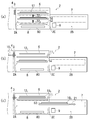
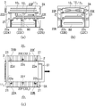
次に、図3(a)~(c)乃至図5(a)~(c)並びに図6(a)~(c)乃至図12(a)~(c)を参照して本実施の形態の動作を説明する。なお、図6(c)乃至図12(c)の平面図については、本発明の理解を容易にするため、適宜基板10及びマグネット12の図示を省略する。
また、上述した第1のマスク付き基板51は、第1のマスク機構(第1のマスク)111、第1の基板101、第1のマグネット121から構成され、第2のマスク付き基板52は、第2のマスク機構(第2のマスク)112、第1の基板102、第1のマグネット122から構成されているものとする。
以下、アライメント領域6aにおいて第1のマスク付き基板51が作成され、蒸発源9において蒸発材料の蒸発を開始した後、真空槽2内で新しい基板10が搬入されるのを待っている場合を前提として本実施の形態の動作を説明する。
まず、図3(a)に示すように、第1の基板昇降機構221を下降させることにより、図6(a)~(c)に示すように、第1のマスク付き基板51を基板搬送機構21上に載置する。本明細書では、この位置を「蒸着開始位置21a」と称する。
本実施の形態の場合、第1の基板昇降機構221の基板昇降部材22A~22Cは、それぞれ基板搬送機構21のローラの間に位置するように配設されており、また各基板昇降部材22A~22Cの支持部22a~22cを、第1のマスク機構111の縁部の線分11A、11Bに対して垂直となる位置に配置しておくことにより、第1のマスク付き基板51は、第1の基板昇降機構221を下降させる際に、各基板昇降部材22A~22Cの支持部22a~22cから円滑に基板搬送機構21に受け渡される。
一方、第2のマスク機構112を第2の基板昇降機構222によって支持してアライメント領域6a内に配置するとともに、第2のマグネット122を、アライメント領域6aの上部に配置し、第2の基板102の搬入を待つ。
そして、基板搬送機構21のローラを動作させ、図3(b)及び図7(a)~(c)に示すように、第1のマスク付き基板51を蒸着領域7に向って搬送して、第1の基板101に対して蒸着を開始する。
なお、この時点で、第1の基板昇降機構221の基板昇降部材22A~22Cの支持部22a~22cを、第2のマスク機構112の縁部の線分11A、11Bに対して平行となる位置に配置しておく。
その後、図3(c)及び図8(a)~(c)に示すように、第2の基板102をアライメント室2A内に搬入し、アライメント領域6aにおいてアライメントを行う。
その後、図3(c)及び図8(a)~(c)に示すように、第2の基板102をアライメント室2A内に搬入し、アライメント領域6aにおいてアライメントを行う。
さらに、図4(a)に示すように、第2の基板102を第2のマスク機構112に取り付けて第2のマスク付き基板52を作成した後、第2の基板昇降機構222を下降させて第2のマスク付き基板52をアライメント領域6aから蒸着開始位置21aを通過して待機領域8に移動し、各基板昇降部材22D~22Fの支持部22d~22fを冷却プレート80の上面より若干低い位置まで移動させることにより、第2のマスク付き基板52を第2の基板昇降機構222から冷却プレート80に受け渡す。
これにより、第2のマスク付き基板52の第2のマスク機構112が冷却プレート80上に密着され、第2の基板102が冷却される。
この場合、図9(a)~(c)に示すように、第2の基板昇降機構222を下降させる際に、基板搬送機構21の各ローラを、アライメント室2Aの両側の側壁部23、24側にそれぞれ移動させて長さを縮めることにより、第2のマスク機構112の縁部(線分11A及び11Bの部分)が基板搬送機構21の各ローラと接触しないようにする。
この場合、図9(a)~(c)に示すように、第2の基板昇降機構222を下降させる際に、基板搬送機構21の各ローラを、アライメント室2Aの両側の側壁部23、24側にそれぞれ移動させて長さを縮めることにより、第2のマスク機構112の縁部(線分11A及び11Bの部分)が基板搬送機構21の各ローラと接触しないようにする。
また、第1の基板昇降機構211の基板昇降部材22A~22Cの支持部22a~22cは、第2のマスク機構112の縁部の線分11A、11Bに対して平行となる位置に配置されているため、基板昇降部材22A~22Cの支持部22a~22cが第2のマスク機構112の縁部に接触することはない。
そして、この動作により、第2のマスク付き基板52の第2のマスク機構112が冷却プレート80上に密着し、第2の基板102が冷却される。
そして、この動作により、第2のマスク付き基板52の第2のマスク機構112が冷却プレート80上に密着し、第2の基板102が冷却される。
一方、図4(a)(b)及び図10(a)~(c)に示すように、第1のマスク付き基板51については、蒸着室2Bからアライメント室2Aに向って搬送し、第1の基板101表面への蒸着を続行する。
なお、この時点で、第1の基板昇降機構211の基板昇降部材22A~22Cの支持部22a~22cを、第2のマスク機構112の縁部の線分11A、11Bに対して垂直となる位置に配置しておく。
そして、図4(c)に示すように、第1のマスク付き基板51への蒸着が終了した後、図5(a)及び図11(a)~(c)に示すように、第1及び第2の基板昇降機構221、222を上昇させることにより、第1のマスク付き基板51をアライメント室2A内のアライメント領域6aに移動させるとともに、第2のマスク付き基板52を、基板搬送機構21の上方の位置まで移動させる。
この場合、図11(a)~(c)に示すように、第2の基板昇降機構222を上昇させる際に、基板搬送機構21の各ローラを、アライメント室2Aの両側の側壁部23、24側にそれぞれ移動させて長さを縮めることにより、第2のマスク機構112の縁部(線分11A及び11Bの部分)が基板搬送機構21の各ローラと接触しないようにする。
その後、図5(b)に示すように、アライメント室2Aのアライメント領域6aにおいて、第1のマスク機構111と第1の基板101とを分離し、第1の基板101をアライメント室2Aから真空搬送ユニット4へ搬出する。
この動作と並行して、図12(a)~(c)に示すように、基板搬送機構21の各ローラを伸ばした後、第2の基板昇降機構222を下降させることにより、第2のマスク付き基板52を基板搬送機構21上の蒸着開始位置21aに配置する。
そして、基板搬送機構21のローラを動作させ、図5(c)に示すように、第2のマスク付き基板52を蒸着領域7に向って搬送して、第2の基板102に対して蒸着を開始する。
この動作と並行して、図5(c)に示すように、新たな基板である第3の基板103をアライメント室2A内に搬入し、アライメント領域6aにおいてアライメントを行う。
以下、上述した工程を、複数の基板10について連続して行う。
以上述べた本実施の形態にあっては、真空槽2内に、アライメント領域6aを有する基板搬入搬出領域6と、蒸着領域7と、待機領域8とが設けられ、第1及び第2のマスク付き基板51、52を、アライメント領域6aと待機領域8との間の蒸着開始位置21aと、蒸着領域7との間において第1の搬送機構によって搬送する一方で、第1及び第2のマスク付き基板51、52を、アライメント領域6aと蒸着開始位置21aとの間、並びに、蒸着開始位置21aと待機領域8との間において第1及び第2の基板昇降機構221、222によってそれぞれ搬送し、さらに、待機領域8が基板搬送機構21に対して例えば上下方向に重ならない位置に設けられていることから、第1及び第2のマスク付き基板51、52のうち例えば第2のマスク付き基板52を、第2の基板昇降機構222によって待機領域8まで搬送して待機させている間に、第1のマスク付き基板51に対しては、第1の基板昇降機構221によって蒸着開始位置21aまで搬送し、基板搬送機構21によって蒸着領域7に搬送して蒸着を行うことができる。そして、蒸着が終了した第1の基板101を真空槽2の外へ搬出するとともに、待機領域8に待機させておいた第2のマスク付き基板52を蒸着開始位置21aに配置することができる。
以上述べた本実施の形態にあっては、真空槽2内に、アライメント領域6aを有する基板搬入搬出領域6と、蒸着領域7と、待機領域8とが設けられ、第1及び第2のマスク付き基板51、52を、アライメント領域6aと待機領域8との間の蒸着開始位置21aと、蒸着領域7との間において第1の搬送機構によって搬送する一方で、第1及び第2のマスク付き基板51、52を、アライメント領域6aと蒸着開始位置21aとの間、並びに、蒸着開始位置21aと待機領域8との間において第1及び第2の基板昇降機構221、222によってそれぞれ搬送し、さらに、待機領域8が基板搬送機構21に対して例えば上下方向に重ならない位置に設けられていることから、第1及び第2のマスク付き基板51、52のうち例えば第2のマスク付き基板52を、第2の基板昇降機構222によって待機領域8まで搬送して待機させている間に、第1のマスク付き基板51に対しては、第1の基板昇降機構221によって蒸着開始位置21aまで搬送し、基板搬送機構21によって蒸着領域7に搬送して蒸着を行うことができる。そして、蒸着が終了した第1の基板101を真空槽2の外へ搬出するとともに、待機領域8に待機させておいた第2のマスク付き基板52を蒸着開始位置21aに配置することができる。
このように、本実施の形態によれば、第1及び第2の基板101、102に対して同時に搬送及び蒸着を行うことができるので、従来技術に比べ、基板搬送の待ち時間を最小限にして蒸発材料の無駄を減らすことができる。
また、本実施の形態では、真空槽2内において、第1及び第2のマスク付き基板51、52の順序を入れ替えることができるので、成膜の待ち時間を最小限にして蒸発材料の無駄を減らすことができる。
さらに、本実施の形態では、待機領域8に冷却プレート80が設けられており、マスク機構11の温度の上昇を抑えることができるので、マスクの膨張を防止してより精密なマスク蒸着を行うことができる。
さらにまた、本実施の形態では、基板搬入搬出領域6にアライメント領域6aが設けられていることから、基板10とマスク機構11とのアライメントを行いつつ蒸着を行うことができるので、プロセス全体のタクトタイムを短縮することができ、これにより蒸発材料の無駄を一層減らすことができる。
加えて、本実施の形態では、基板搬送機構21が、第1及び第2のマスク付き基板51、52を支持して水平方向に搬送するように構成された複数のローラを有するとともに、第1及び第2の基板昇降機構221、222が、基板搬送機構21の複数のローラの間に設けられ第1及び第2のマスク付き基板51、52を支持して鉛直方向に搬送するように構成された複数のピン状の基板昇降部材22A~22Fを有するとともに、基板搬送機構21のローラが、真空槽2の両側の内側壁部23、24において水平方向に伸縮自在に設けられており、さらに、第1及び第2の基板昇降機構221、222の基板昇降部材22A~22Fが、水平方向に延びる支持部22a~22fを有し、これら支持部22a~22fが水平方向に例えば90度回転するように構成されていることから、ロボットのような複雑な基板搬送機構を用いることなく、第1及び第2のマスク付き基板51、52を、基板搬送機構21から第1及び第2の基板昇降機構221、222へ受け渡し、又は第1及び第2の基板昇降機構221、222から基板搬送機構21へ受け渡す動作を円滑に行うことができる。
なお、本発明は上述の実施の形態に限られることなく、種々の変更を行うことができる。
例えば、上記実施の形態においては、第1及び第2の基板昇降機構221、222が、それぞれ3個の基板昇降部材22A~22C並びに22D~22Fを有するようにしたが、本発明はこれに限られず、それぞれ4個以上の基板昇降部材を設けることもできる。
例えば、上記実施の形態においては、第1及び第2の基板昇降機構221、222が、それぞれ3個の基板昇降部材22A~22C並びに22D~22Fを有するようにしたが、本発明はこれに限られず、それぞれ4個以上の基板昇降部材を設けることもできる。
なお、この場合においても、それぞれの基板昇降部材の支持部の重心が一致するように構成することが好ましい。
また、上記実施の形態においては、基板搬入搬出領域6にアライメント領域6aを設けるようにしたが、本発明はこれに限られず、他の真空槽でアライメントした基板とマスク機構を真空槽2内に搬入して蒸着を行うことも可能である。
また、上記実施の形態においては、基板搬入搬出領域6にアライメント領域6aを設けるようにしたが、本発明はこれに限られず、他の真空槽でアライメントした基板とマスク機構を真空槽2内に搬入して蒸着を行うことも可能である。
さらに、上記実施の形態においては、基板搬入搬出領域6を基板搬送機構21の上方に設けるとともに、待機領域8を基板搬送機構21の下方に設けるようにしたが、基板搬入搬出領域6を基板搬送機構21の下方に設けるとともに、待機領域8を基板搬送機構21の上方に設けることも可能である。
さらにまた、基板搬入搬出領域6及び待機領域8を基板搬送機構21の側方に設けることもできる。
ただし、設置面積を小さくする観点からは、例えば上記実施の形態のように、基板搬入搬出領域6及び待機領域8を基板搬送機構21の上下の位置に設けることが好ましい。
ただし、設置面積を小さくする観点からは、例えば上記実施の形態のように、基板搬入搬出領域6及び待機領域8を基板搬送機構21の上下の位置に設けることが好ましい。
加えて、待機領域8を二つ以上設けることも可能である。この場合には、各待機領域8に対応するように、個別の搬送機構を設けることが好ましい。
さらにまた、上記実施の形態においては、基板10を水平にした状態で水平方向及び鉛直方向に移動させる場合を例にとって説明したが、本発明はこれに限られず、基板を鉛直にした状態で鉛直方向及び水平方向に移動させる場合にも適用することができるものである。この場合には、鉛直方向に向けられた基板に対し、蒸発源から水平方向に蒸気を放出して蒸着を行うことになる。
さらにまた、上記実施の形態においては、基板10を水平にした状態で水平方向及び鉛直方向に移動させる場合を例にとって説明したが、本発明はこれに限られず、基板を鉛直にした状態で鉛直方向及び水平方向に移動させる場合にも適用することができるものである。この場合には、鉛直方向に向けられた基板に対し、蒸発源から水平方向に蒸気を放出して蒸着を行うことになる。
1…蒸着装置
2…真空槽
2A…アライメント室
2B…蒸着室
5…アライメント機構
6…基板搬入搬出領域
6a…アライメント領域
7…蒸着領域
8…待機領域
9…蒸発源
10…基板
101…第1の基板
102…第2の基板
11…マスク機構
111…第1のマスク機構
112…第2のマスク機構
12…マグネット
121…第1のマグネット
122…第2のマグネット
21…基板搬送機構(第1の搬送機構)
221…第1の基板昇降機構(第2の搬送機構)
222…第2の基板昇降機構(第2の搬送機構)
21a…蒸着開始位置
22A~22F…基板昇降部材
22a~22f…支持部
51…第1のマスク付き基板
52…第2のマスク付き基板
80…冷却プレート(冷却手段)
2…真空槽
2A…アライメント室
2B…蒸着室
5…アライメント機構
6…基板搬入搬出領域
6a…アライメント領域
7…蒸着領域
8…待機領域
9…蒸発源
10…基板
101…第1の基板
102…第2の基板
11…マスク機構
111…第1のマスク機構
112…第2のマスク機構
12…マグネット
121…第1のマグネット
122…第2のマグネット
21…基板搬送機構(第1の搬送機構)
221…第1の基板昇降機構(第2の搬送機構)
222…第2の基板昇降機構(第2の搬送機構)
21a…蒸着開始位置
22A~22F…基板昇降部材
22a~22f…支持部
51…第1のマスク付き基板
52…第2のマスク付き基板
80…冷却プレート(冷却手段)
Claims (9)
- 複数の基板を搬入又は搬出可能な真空槽と、
前記真空槽内に設けられ、搬入された基板とマスクを合体させ、かつ、蒸着が終了した基板とマスクとを分離して当該基板を当該真空槽の外へ搬出する基板搬入搬出領域と、
前記真空槽内に設けられ、合体された当該基板上に当該マスクを介して蒸着を行う蒸着領域と、
前記真空槽内に設けられ、合体された当該基板及び当該マスクを待機させる待機領域と、
合体された当該基板及び当該マスクを、前記基板搬入搬出領域及び前記待機領域の間に位置する蒸着開始位置と、前記蒸着領域との間において搬送する第1の搬送機構と、
合体された複数の当該基板及び当該マスクを、前記基板搬入搬出領域と前記蒸着開始位置との間、並びに、当該蒸着開始位置と前記待機領域との間においてそれぞれ搬送する複数の第2の搬送機構を備え、
前記待機領域が、前記第1の搬送機構に対して重ならない位置に設けられている蒸着装置。 - 前記基板搬入搬出領域に、搬入された基板とマスクとをアライメントするアライメント領域が設けられている請求項1記載の蒸着装置。
- 前記待機領域が、前記第1の搬送機構の下方に設けられている請求項1又は2のいずれか1項記載の蒸着装置。
- 前記基板搬入搬出領域が、前記第1の搬送機構の上方に設けられている請求項3記載の蒸着装置。
- 前記待機領域に、前記基板を冷却する冷却手段が設けられている請求項1乃至4のいずれか1項記載の蒸着装置。
- 前記第1の搬送機構が、前記基板及び前記マスクを支持して水平方向に搬送するように構成された複数のローラを有するとともに、前記第2の搬送機構が、前記第1の搬送機構の複数のローラの間に設けられ、前記基板及び前記マスクを支持して鉛直方向に搬送するように構成された複数のピン状の基板昇降部材を有する請求項3乃至5のいずれか1項記載の蒸着装置。
- 前記第1の搬送機構のローラが、前記真空槽の両側の内側壁部において水平方向に伸縮自在に設けられている請求項6記載の蒸着装置。
- 前記第2の搬送機構の基板昇降部材が、水平方向に延びる支持部を有し、当該支持部が水平方向に所定の角度回転するように構成されている請求項6又は7のいずれか1項記載の蒸着装置。
- 複数の基板を搬入又は搬出可能な真空槽と、前記真空槽内に設けられ、搬入された基板とマスクを合体させ、かつ、蒸着が終了した基板とマスクとを分離して当該基板を当該真空槽の外へ搬出する基板搬入搬出領域と、前記真空槽内に設けられ、合体された当該基板上に当該マスクを介して蒸着を行う蒸着領域と、前記真空槽内に設けられ、合体された当該基板及び当該マスクを待機させる待機領域と、合体された当該基板及び当該マスクを、前記基板搬入搬出領域及び前記待機領域の間に位置する蒸着開始位置と、前記蒸着領域との間において搬送する第1の搬送機構と、合体された複数の当該基板及び当該マスクを、前記基板搬入搬出領域と前記蒸着開始位置との間、並びに、当該蒸着開始位置と前記待機領域との間においてそれぞれ搬送する複数の第2の搬送機構を備え、前記待機領域が、前記第1の搬送機構に対して重ならない位置に設けられている蒸着装置を用いた蒸着方法であって、
前記真空槽の基板搬入搬出領域において、前記真空槽内に搬入された第1の基板を第1のマスクに合体させる工程と、
合体された当該第1の基板及び当該第1のマスクを前記第1の搬送機構によって前記蒸着領域に搬送し、当該第1のマスクを介して当該第1の基板に対して蒸着を行う工程と、
前記基板搬入搬出領域において、前記真空槽内に搬入された第2の基板と第2のマスクを合体させた後、前記待機領域に配置する工程と、
蒸着が終了した前記第1の基板及び前記第1のマスクを前記第1の搬送機構によって前記基板搬入搬出領域に搬送し、当該第1のマスクから当該第1の基板を分離して当該真空槽の外へ搬出する工程と、
前記第2の基板及び前記第2のマスクを前記第1の搬送機構によって前記蒸着領域に搬送して当該第2の基板及び当該第2のマスク上に蒸着を行う工程と、
前記第1の基板を前記第1のマスクから分離して当該真空槽の外へ搬出する工程と、
前記第1の基板及び前記第1のマスクを前記蒸着領域に搬送して当該第1のマスクを介して当該第1の基板に対して蒸着を行う工程と、
蒸着が終了した前記第2の基板及び前記第2のマスクを前記第1の搬送機構によって前記基板搬入搬出領域に搬送し、当該第2のマスクから当該第2の基板を分離して当該真空槽の外へ搬出する工程とを有し、
前記各工程を連続的に繰り返す蒸着方法。
Priority Applications (1)
| Application Number | Priority Date | Filing Date | Title |
|---|---|---|---|
| JP2012539697A JP5730322B2 (ja) | 2010-10-19 | 2011-10-14 | 蒸着装置及び蒸着方法 |
Applications Claiming Priority (2)
| Application Number | Priority Date | Filing Date | Title |
|---|---|---|---|
| JP2010-234918 | 2010-10-19 | ||
| JP2010234918 | 2010-10-19 |
Publications (1)
| Publication Number | Publication Date |
|---|---|
| WO2012053430A1 true WO2012053430A1 (ja) | 2012-04-26 |
Family
ID=45975145
Family Applications (1)
| Application Number | Title | Priority Date | Filing Date |
|---|---|---|---|
| PCT/JP2011/073619 Ceased WO2012053430A1 (ja) | 2010-10-19 | 2011-10-14 | 蒸着装置及び蒸着方法 |
Country Status (3)
| Country | Link |
|---|---|
| JP (1) | JP5730322B2 (ja) |
| TW (1) | TW201219585A (ja) |
| WO (1) | WO2012053430A1 (ja) |
Cited By (5)
| Publication number | Priority date | Publication date | Assignee | Title |
|---|---|---|---|---|
| WO2014084270A1 (ja) * | 2012-11-28 | 2014-06-05 | コニカミノルタ株式会社 | 有機エレクトロルミネッセンス素子用の薄膜形成装置と薄膜形成方法 |
| JP2014109054A (ja) * | 2012-11-30 | 2014-06-12 | Panasonic Corp | 真空成膜装置 |
| CN105051841A (zh) * | 2013-03-15 | 2015-11-11 | 欧姆龙汽车电子株式会社 | 磁器件 |
| CN111041424A (zh) * | 2018-10-15 | 2020-04-21 | 佳能特机株式会社 | 成膜装置及方法、有机el面板的制造系统以及制造方法 |
| CN112708867A (zh) * | 2020-12-31 | 2021-04-27 | 广东谛思纳为新材料科技有限公司 | 一种往复镀膜设备及镀膜方法 |
Citations (7)
| Publication number | Priority date | Publication date | Assignee | Title |
|---|---|---|---|---|
| JPH09279341A (ja) * | 1996-04-17 | 1997-10-28 | Anelva Corp | トレイ搬送式インライン成膜装置 |
| JPH11131232A (ja) * | 1997-10-31 | 1999-05-18 | Anelva Corp | トレイ搬送式成膜装置 |
| JP2006219760A (ja) * | 2005-02-07 | 2006-08-24 | Semes Co Ltd | 基板処理装置 |
| JP2007211270A (ja) * | 2006-02-07 | 2007-08-23 | Sumitomo Heavy Ind Ltd | 成膜装置 |
| JP2008231575A (ja) * | 2007-03-22 | 2008-10-02 | Samsung Sdi Co Ltd | 保護膜層を蒸着させる装置及び該装置を利用した蒸着方法 |
| JP2008303427A (ja) * | 2007-06-07 | 2008-12-18 | Sumitomo Heavy Ind Ltd | 基板処理装置 |
| JP2009224231A (ja) * | 2008-03-17 | 2009-10-01 | Ulvac Japan Ltd | 有機el製造装置及び有機el製造方法 |
Family Cites Families (4)
| Publication number | Priority date | Publication date | Assignee | Title |
|---|---|---|---|---|
| JP2005211865A (ja) * | 2004-02-02 | 2005-08-11 | Masato Toshima | プラズマ処理装置 |
| JP4476133B2 (ja) * | 2005-02-24 | 2010-06-09 | 東京エレクトロン株式会社 | 処理システム |
| JP3119201U (ja) * | 2005-12-02 | 2006-02-16 | 株式会社島津製作所 | Tftアレイ検査装置 |
| US20110240223A1 (en) * | 2008-11-14 | 2011-10-06 | Tokyo Electron Limited | Substrate processing system |
-
2011
- 2011-10-14 WO PCT/JP2011/073619 patent/WO2012053430A1/ja not_active Ceased
- 2011-10-14 JP JP2012539697A patent/JP5730322B2/ja active Active
- 2011-10-19 TW TW100137901A patent/TW201219585A/zh unknown
Patent Citations (7)
| Publication number | Priority date | Publication date | Assignee | Title |
|---|---|---|---|---|
| JPH09279341A (ja) * | 1996-04-17 | 1997-10-28 | Anelva Corp | トレイ搬送式インライン成膜装置 |
| JPH11131232A (ja) * | 1997-10-31 | 1999-05-18 | Anelva Corp | トレイ搬送式成膜装置 |
| JP2006219760A (ja) * | 2005-02-07 | 2006-08-24 | Semes Co Ltd | 基板処理装置 |
| JP2007211270A (ja) * | 2006-02-07 | 2007-08-23 | Sumitomo Heavy Ind Ltd | 成膜装置 |
| JP2008231575A (ja) * | 2007-03-22 | 2008-10-02 | Samsung Sdi Co Ltd | 保護膜層を蒸着させる装置及び該装置を利用した蒸着方法 |
| JP2008303427A (ja) * | 2007-06-07 | 2008-12-18 | Sumitomo Heavy Ind Ltd | 基板処理装置 |
| JP2009224231A (ja) * | 2008-03-17 | 2009-10-01 | Ulvac Japan Ltd | 有機el製造装置及び有機el製造方法 |
Cited By (7)
| Publication number | Priority date | Publication date | Assignee | Title |
|---|---|---|---|---|
| WO2014084270A1 (ja) * | 2012-11-28 | 2014-06-05 | コニカミノルタ株式会社 | 有機エレクトロルミネッセンス素子用の薄膜形成装置と薄膜形成方法 |
| JPWO2014084270A1 (ja) * | 2012-11-28 | 2017-01-05 | コニカミノルタ株式会社 | 有機エレクトロルミネッセンス素子用の薄膜形成装置と薄膜形成方法 |
| JP2014109054A (ja) * | 2012-11-30 | 2014-06-12 | Panasonic Corp | 真空成膜装置 |
| CN105051841A (zh) * | 2013-03-15 | 2015-11-11 | 欧姆龙汽车电子株式会社 | 磁器件 |
| CN111041424A (zh) * | 2018-10-15 | 2020-04-21 | 佳能特机株式会社 | 成膜装置及方法、有机el面板的制造系统以及制造方法 |
| CN111041424B (zh) * | 2018-10-15 | 2023-05-05 | 佳能特机株式会社 | 成膜装置、制造系统、有机el面板的制造系统、成膜方法及有机el元件的制造方法 |
| CN112708867A (zh) * | 2020-12-31 | 2021-04-27 | 广东谛思纳为新材料科技有限公司 | 一种往复镀膜设备及镀膜方法 |
Also Published As
| Publication number | Publication date |
|---|---|
| TW201219585A (en) | 2012-05-16 |
| JPWO2012053430A1 (ja) | 2014-02-24 |
| JP5730322B2 (ja) | 2015-06-10 |
Similar Documents
| Publication | Publication Date | Title |
|---|---|---|
| CN101060093B (zh) | 基板搬送处理装置 | |
| JP2009105081A (ja) | 基板処理装置 | |
| JP5511273B2 (ja) | 基板処理装置及び基板処理方法 | |
| JP5173699B2 (ja) | 有機elデバイス製造装置 | |
| CN104488358B (zh) | 烘焙处理系统及有机el元件的有机功能膜的层叠体的制造方法 | |
| JP5730322B2 (ja) | 蒸着装置及び蒸着方法 | |
| JP2009010287A (ja) | 基板の処理システム | |
| JP2009094242A (ja) | 基板保持機構、基板受渡機構、及び基板処理装置 | |
| JP6255544B2 (ja) | 真空処理装置 | |
| JP2008258209A (ja) | 塗布、現像装置及びその方法並びに記憶媒体 | |
| JP2005340425A (ja) | 真空処理装置 | |
| CN102938447A (zh) | 有机el设备制造装置 | |
| JP4850372B2 (ja) | 基板処理装置 | |
| CN102194665A (zh) | 处理室、半导体制造设备及使用其的基板处理方法 | |
| KR101409808B1 (ko) | 기판처리시스템 | |
| JP2014070242A (ja) | 真空蒸着装置及び真空蒸着方法 | |
| KR20180056989A (ko) | 막 증착 장치 및 방법 | |
| CN101908469A (zh) | 处理装置 | |
| KR20110066864A (ko) | 기판처리장치, 기판처리방법 및 이 기판처리방법을 실행시키기 위한 프로그램을 기록한 기록매체 | |
| KR101958411B1 (ko) | 막 증착 장치 및 방법 | |
| JP5362232B2 (ja) | 基板処理装置 | |
| KR100905394B1 (ko) | 평판표시소자 제조장치 | |
| KR100934765B1 (ko) | 평판표시소자 제조장치 | |
| KR20070015759A (ko) | 평판표시소자 제조장치 | |
| CN106784394B (zh) | 用于附着玻璃与掩模的设备及方法、以及用于装载基板的系统及方法 |
Legal Events
| Date | Code | Title | Description |
|---|---|---|---|
| 121 | Ep: the epo has been informed by wipo that ep was designated in this application |
Ref document number: 11834270 Country of ref document: EP Kind code of ref document: A1 |
|
| ENP | Entry into the national phase |
Ref document number: 2012539697 Country of ref document: JP Kind code of ref document: A |
|
| NENP | Non-entry into the national phase |
Ref country code: DE |
|
| 122 | Ep: pct application non-entry in european phase |
Ref document number: 11834270 Country of ref document: EP Kind code of ref document: A1 |