WO2012042979A1 - 電線の止水中間スプライス部の製造方法及び電線の止水中間スプライス部 - Google Patents
電線の止水中間スプライス部の製造方法及び電線の止水中間スプライス部 Download PDFInfo
- Publication number
- WO2012042979A1 WO2012042979A1 PCT/JP2011/063068 JP2011063068W WO2012042979A1 WO 2012042979 A1 WO2012042979 A1 WO 2012042979A1 JP 2011063068 W JP2011063068 W JP 2011063068W WO 2012042979 A1 WO2012042979 A1 WO 2012042979A1
- Authority
- WO
- WIPO (PCT)
- Prior art keywords
- water
- protective sheet
- electric wire
- stop
- agent
- Prior art date
- Legal status (The legal status is an assumption and is not a legal conclusion. Google has not performed a legal analysis and makes no representation as to the accuracy of the status listed.)
- Ceased
Links
Images












Classifications
-
- H—ELECTRICITY
- H01—ELECTRIC ELEMENTS
- H01R—ELECTRICALLY-CONDUCTIVE CONNECTIONS; STRUCTURAL ASSOCIATIONS OF A PLURALITY OF MUTUALLY-INSULATED ELECTRICAL CONNECTING ELEMENTS; COUPLING DEVICES; CURRENT COLLECTORS
- H01R43/00—Apparatus or processes specially adapted for manufacturing, assembling, maintaining, or repairing of line connectors or current collectors or for joining electric conductors
- H01R43/20—Apparatus or processes specially adapted for manufacturing, assembling, maintaining, or repairing of line connectors or current collectors or for joining electric conductors for assembling or disassembling contact members with insulating base, case or sleeve
-
- H—ELECTRICITY
- H01—ELECTRIC ELEMENTS
- H01B—CABLES; CONDUCTORS; INSULATORS; SELECTION OF MATERIALS FOR THEIR CONDUCTIVE, INSULATING OR DIELECTRIC PROPERTIES
- H01B7/00—Insulated conductors or cables characterised by their form
- H01B7/17—Protection against damage caused by external factors, e.g. sheaths or armouring
- H01B7/28—Protection against damage caused by moisture, corrosion, chemical attack or weather
- H01B7/282—Preventing penetration of fluid, e.g. water or humidity, into conductor or cable
- H01B7/2825—Preventing penetration of fluid, e.g. water or humidity, into conductor or cable using a water impermeable sheath
-
- H—ELECTRICITY
- H01—ELECTRIC ELEMENTS
- H01R—ELECTRICALLY-CONDUCTIVE CONNECTIONS; STRUCTURAL ASSOCIATIONS OF A PLURALITY OF MUTUALLY-INSULATED ELECTRICAL CONNECTING ELEMENTS; COUPLING DEVICES; CURRENT COLLECTORS
- H01R4/00—Electrically-conductive connections between two or more conductive members in direct contact, i.e. touching one another; Means for effecting or maintaining such contact; Electrically-conductive connections having two or more spaced connecting locations for conductors and using contact members penetrating insulation
- H01R4/70—Insulation of connections
-
- H—ELECTRICITY
- H01—ELECTRIC ELEMENTS
- H01R—ELECTRICALLY-CONDUCTIVE CONNECTIONS; STRUCTURAL ASSOCIATIONS OF A PLURALITY OF MUTUALLY-INSULATED ELECTRICAL CONNECTING ELEMENTS; COUPLING DEVICES; CURRENT COLLECTORS
- H01R43/00—Apparatus or processes specially adapted for manufacturing, assembling, maintaining, or repairing of line connectors or current collectors or for joining electric conductors
- H01R43/005—Apparatus or processes specially adapted for manufacturing, assembling, maintaining, or repairing of line connectors or current collectors or for joining electric conductors for making dustproof, splashproof, drip-proof, waterproof, or flameproof connection, coupling, or casing
-
- H—ELECTRICITY
- H02—GENERATION; CONVERSION OR DISTRIBUTION OF ELECTRIC POWER
- H02G—INSTALLATION OF ELECTRIC CABLES OR LINES, OR OF COMBINED OPTICAL AND ELECTRIC CABLES OR LINES
- H02G15/00—Cable fittings
- H02G15/08—Cable junctions
- H02G15/18—Cable junctions protected by sleeves, e.g. for communication cable
- H02G15/1806—Heat shrinkable sleeves
- H02G15/1813—Wraparound or slotted sleeves
-
- Y—GENERAL TAGGING OF NEW TECHNOLOGICAL DEVELOPMENTS; GENERAL TAGGING OF CROSS-SECTIONAL TECHNOLOGIES SPANNING OVER SEVERAL SECTIONS OF THE IPC; TECHNICAL SUBJECTS COVERED BY FORMER USPC CROSS-REFERENCE ART COLLECTIONS [XRACs] AND DIGESTS
- Y10—TECHNICAL SUBJECTS COVERED BY FORMER USPC
- Y10T—TECHNICAL SUBJECTS COVERED BY FORMER US CLASSIFICATION
- Y10T29/00—Metal working
- Y10T29/49—Method of mechanical manufacture
- Y10T29/49002—Electrical device making
- Y10T29/49117—Conductor or circuit manufacturing
Definitions
- This invention relates to a technique for stopping water at an intermediate splice part connecting electric wires.
- Patent Document 1 Conventionally, there is a technique disclosed in Patent Document 1 or Patent Document 2 as a technique for stopping the intermediate splice portion.
- Patent Document 1 a resin case is covered with a wire connection portion, an ultraviolet curable adhesive is filled in the resin case, and the adhesive is cured by irradiating ultraviolet rays from the outside of the resin case.
- Patent Document 2 a splice part or the like is placed on the top surface of the insulating resin sheet to which the adhesive is applied, a photo-curing silicone resin is applied thereto, and then the insulating resin sheet is wound around the splice part or the like. Then, after irradiating light from the opening of both ends of the wound insulating resin sheet to cure the photocurable silicone resin, the internal photocurable silicone resin is naturally cured.
- the water-stopping agent applied to the intermediate splice part shrinks between application and curing, or tries to enter between the core wires or between the electric wires. For this reason, the volume of the water-stopping agent remaining on the surface of the intermediate splice part may decrease, and the surface may be recessed. In this case, in the case of Patent Document 1, a gap is generated between the resin case and the cured adhesive. Further, even in the case of Patent Document 2, since the insulating resin sheet coated with the adhesive has a certain degree of form maintainability, there is still a gap between the insulating resin sheet and the cured photocured silicone resin. .
- the gap grows greatly, and there is a risk that the water stop thickness at that portion will be reduced. Moreover, there is a possibility that the gap becomes a liquid pool and becomes a factor of deteriorating the water stop portion.
- the present invention suppresses a gap between the water stop agent supplied to the intermediate splice part and the protective sheet covering the water stop agent when the intermediate splice part connecting the wires is stopped. With the goal.
- a method for manufacturing a water-stop intermediate splice part of an electric wire includes: (a) supplying a water-stop agent to the intermediate splice part of the electric wire; A step of covering the water-stopping agent supplied to the intermediate splice part, and (c) following the deformation of the surface of the water-stopping agent and deforming the protective sheet to deform the surface of the water-stopping agent and the protective sheet. And a step of curing the water-stopping agent while maintaining the contacted state.
- a second aspect is a method for manufacturing a water-stop intermediate splice part of an electric wire according to the first aspect, and follows the deformation of the surface of a water-stop agent supplied to the intermediate splice part as the protective sheet.
- a protective sheet having a deformable flexibility is used.
- the third aspect is a method for manufacturing a water-stop middle splice part of an electric wire according to the first or second aspect, and a protective sheet having self-adhesiveness is used as the protective sheet.
- a fourth aspect is a method for producing a water-stop intermediate splice part of an electric wire according to any one of the first to third aspects, wherein the water-stopper has photocurability, and the protective sheet has the above-mentioned Light that cures the water-stopping agent can be transmitted, and the water-stopping agent is cured by irradiating light that cures the water-stopping agent in the step (c).
- a fifth aspect is a method for producing a water-stop intermediate splice part of an electric wire according to any one of the first to fourth aspects, wherein the water-stopper is thermosetting, moisture-curing, cationic polymerization curing. It is made into the photocurable resin to which at least 1 of property, anion polymerization sclerosis
- a sixth aspect is a method of manufacturing a water-stop middle splice part of an electric wire according to any one of the first to fifth aspects, wherein in the step (b), the protective sheet is applied while applying force from around. It winds around the water stop agent supplied to the intermediate splice part.
- 7th aspect is a manufacturing method of the water stop intermediate splice part of the electric wire which concerns on the 6th aspect, Comprising: The water stop which supplied the said protection sheet to the said intermediate splice part in the state which applied tension
- An eighth aspect is a method for manufacturing a water-stop intermediate splice part of an electric wire according to the sixth or seventh aspect, wherein the protective sheet is supplied to the intermediate splice part while being sandwiched between a pair of rollers. Wrap around the liquid.
- a ninth aspect is a method for manufacturing a water-stop intermediate splice part of an electric wire according to any one of the first to eighth aspects, wherein the protective sheet is formed in the intermediate splice part during the step (b). Wrapped around the water-stopping agent supplied and drawn out in a state of being overlaid outward, so that the overlapped portion of the protective sheet is rubbed and the water-stopping agent in the overlapped portion is intermediate It is pushed toward the splice part.
- the water stop intermediate splice portion of the electric wire includes an intermediate splice portion of the electric wire, a water stop agent supplied to the intermediate splice portion and cured, and a surface of the water stop agent supplied to the intermediate splice portion. And a protective sheet that has a flexibility that can be deformed following the deformation, and covers the water-stopping agent in close contact with the surface of the water-stopping agent.
- the eleventh aspect is a water-stop middle splice part of an electric wire according to the tenth aspect, wherein the protective sheet is a protective sheet having self-adhesiveness.
- a twelfth aspect is a water-stop middle splice part of an electric wire according to the tenth or eleventh aspect, wherein the water-stopping agent has photocurability, and the protective sheet is a light that hardens the water-stopping agent. Can be transmitted.
- a thirteenth aspect is a water stop intermediate splice part of an electric wire according to any one of the tenth to twelfth aspects, wherein the water stop agent is thermosetting, moisture curable, cationic polymerization curable, anion
- the photocurable resin is provided with at least one of polymerization curability and addition reaction curability.
- the surface of the water-stopping agent is deformed following the deformation of the surface of the water-stopping agent to maintain the surface of the water-stopping agent and the protective sheet in close contact with each other.
- the gap between the water stop agent supplied to the intermediate splice portion and the protective sheet covering the water stop agent is suppressed. be able to.
- the protective sheet having flexibility that can be deformed following the deformation of the surface of the water-stopping agent supplied to the intermediate splice part is used as the protective sheet, the protective sheet is supplied to the intermediate splice part.
- the clearance gap between the water-stopper made and the protective sheet which covers the water-stopper can be suppressed.
- the protective sheet since the protective sheet has self-adhesiveness, when the protective sheet is covered by being wrapped around the intermediate splice part and the water-stopping agent, the covered state is maintained and the workability is excellent. .
- the waterstop agent can be cured relatively quickly.
- the waterstop agent can be cured even in the interior not exposed to light.
- the water stop agent easily enters between the electric wires, so that the water stop between the electric wires can be more reliably performed.
- the protective sheet by applying tension to the protective sheet, the protective sheet can be wound while applying force from around.
- the protective sheet can be wound while applying a force from the surroundings due to the force between the pair of rollers.
- the protective sheet is wound around the water-stopping agent supplied to the intermediate splice part and pulled out in a state of being overlapped outward, and the overlapping part of the protective sheet is Since the water-stopping agent in the overlapping portion is pushed toward the intermediate splice portion so as to be squeezed, the desired water-stopping agent can be supplied to the intermediate splice portion, and the water-stopping performance is stabilized.
- the surface of the water-stopping agent is deformed following the deformation of the surface of the water-stopping agent to maintain the surface of the water-stopping agent and the protective sheet in close contact with each other.
- the liquid medicine is cured. For this reason, when water-stopping the intermediate splice part which connected the electric wires, the clearance gap between the water stop agent supplied to the said intermediate splice part and the protective sheet which covers the water stop agent can be suppressed.
- the protective sheet since the protective sheet has self-adhesiveness, when the protective sheet is covered by wrapping around the intermediate splice part and the waterstop agent, the covered state is maintained, and the workability is excellent. .
- the waterstop agent can be cured relatively quickly.
- the waterstop agent can be cured even in the interior not exposed to light.
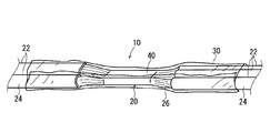
- FIG. 1 is a perspective view showing a water-stop middle splice 10 of an electric wire.
- the electric wire water stop intermediate splice 10 includes an electric wire intermediate splice 20, a water stop agent 40, and a protective sheet 30.
- the intermediate splice portion 20 is obtained by partially removing the covering portion 24 at the intermediate portion in the longitudinal direction of the electric wire 22 to expose the core wire portion 26, and joining the core wire portion 26 of another electric wire 22 to the core wire portion 26. .
- the core wire portion 26 of the other electric wire 22 may be exposed at a middle portion in the longitudinal direction of the electric wire 22 or may be exposed at an end portion of the electric wire 22.
- the electric wire 22 should just be two or more.
- the joining of the core wire portions 26 is performed by resistance welding, ultrasonic welding, laser welding, or the like, or by crimping an intermediate crimp terminal.
- the water-stopping agent 40 is distributed around the intermediate splice portion 20, particularly on the outer peripheral surface of the core wire portion 26 exposed at the intermediate splice portion 20 and the outer peripheral surface of the covering portion 24 before and after the core wire portion 26 in the longitudinal direction of the electric wire 22. Supplied to pass.
- the water-stopping agent 40 is preferably supplied so as to be filled in between the covering portions 24 of the plurality of electric wires 22 on both sides in the longitudinal direction of the exposed core portion 26.
- the fluidity is such that it can be distributed to each part of the intermediate splice part 20 as described above, and the viscosity can maintain the supplied state to some extent. It is a liquid that has Then, after the water-stopping agent 40 is supplied to the intermediate splice unit 20, it is cured.
- a curable resin for example, a thermosetting resin such as an epoxy resin or an acrylic resin can be used.
- a moisture curable resin typified by moisture curable silicone can be used.
- a photocurable resin such as a UV (ultraviolet) curable resin having a photoinitiator and mainly comprising an acrylate oligomer such as urethane acrylate, silicone acrylate, and epoxy acrylate and an acrylate monomer. Can also be used.
- a photocurable resin usually a UV curable resin.
- a UV curable resin is used as a water-stopping agent.
- the viscosity of the water-stopping agent 40 is preferably set to a balanced viscosity range in which it is difficult to flow laterally after resin discharge and flows when subjected to external stress, for example, 10 Pa ⁇ s to 100 Pa ⁇ s. It is preferable to be in the range.
- the UV light irradiated from the outside is blocked by the large number of electric wires 22, so that the water stop agent 40 that has entered between the electric wires 22 is exposed to the UV. It becomes a dark part with respect to light irradiation. Therefore, even when a UV curable resin is used, it is preferable to use a UV curable resin that has a property of being cured without being exposed to UV light.
- properties that the UV curable resin has in addition to UV curing include at least one of other properties of reaction curing such as thermal curing, moisture curing, cationic polymerization curing, anionic polymerization curing, and addition reaction.
- a heat-curing UV curable resin having a composition disclosed in Japanese Patent Application Laid-Open No. 2010-150517 is preferably adjusted to a high viscosity.
- a thermosetting imparted UV resin containing a compound of an (latent) thermosetting initiator amine compound and an epoxy resin, adjusted to a high viscosity is also suitable.
- a UV curable resin that is reactive at room temperature when mixing two liquids as disclosed in JP 2010-154733 A and adjusted to a high viscosity can also be used.
- the protective sheet 30 covers at least the water-stopping agent 40 in a state of being in close contact with the surface of the water-stopping agent 40 that is supplied to the intermediate splice unit 20 and hardened.
- a mode example in which the protective sheet 30 covers the water stopping agent 40 will be described later.
- the protective sheet 30 has a flexibility that can be deformed following the deformation of the surface of the water-stopping agent 40 supplied to the intermediate splice unit 20. That is, the water-stopping agent 40 supplied to the intermediate splice part 20 contracts until it hardens, or tries to enter between the exposed core part 26 or the electric wires 22. For this reason, the surface of the water stopping agent 40 may be recessed more than the state immediately after supply.
- the protective sheet 30 deforms unevenly following the shape change of the surface of the water-stopping agent 40. Thereby, the adhesiveness of the surface of the water stop agent 40 and the protection sheet 30 is maintained, and generation
- the protective sheet 30 has an appropriate stretchability so that the protective sheet 30 can be tightly adhered to the outer periphery when the protective sheet 30 is wound around the intermediate splice portion 20 and the waterstop agent 40. .
- the protective sheet 30 has self-adhesive properties so that the protective sheet 30 can be maintained in a state where the protective sheet 30 is being wound around the intermediate splice portion 20 and the water-stopping agent 40 and after being wound.
- the self-adhesiveness means that when the protective sheet 30 is overlaid, even if there are no other adhesives, adhesives, etc., the self-adhesiveness, the fusion property, etc. This means a property of maintaining a close contact state capable of maintaining the state of being wound around the intermediate splice portion 20.
- a wrap sheet of an olefin resin such as polyethylene, polypropylene, polyvinyl chloride, polyvinylidene chloride, and polyvinylidene fluoride, or a wrap of general-purpose resin such as polyester, polyethylene terephthalate, or nylon.
- a sheet can be mentioned.
- a sheet of polyvinyl chloride resin, polyvinylidene chloride resin, or polyvinylidene fluoride resin having particularly good self-adhesion (adhesion) is preferable.
- a resin sheet that is originally poor in self-adhesion it can be applied as a so-called pressure-sensitive adhesive sheet by containing an appropriate plasticizer or pressure-sensitive adhesive.
- the desirable rigidity property of the protective sheet 30 is such that the object to be wrapped also includes a viscous liquid, and the shape flexibly changes to the object to be wrapped in order to cope with the surface shape deformation of the water stopping agent 40 at the time of curing. It has moderate elongation.
- the protective sheet 30 a thin sheet having a thickness of at least 200 ⁇ m or less is preferable, and a sheet having a thickness of 10 to 100 ⁇ m is preferable.
- Desirable Young's modulus (value at room temperature in the measurement direction according to JIS-K7113) is in the range of 500 to 50 MPa when the thickness is 10 to 50 ⁇ m, and 50 to 10 MPa when the thickness is 50 to 100 ⁇ m. .
- the Young's modulus (the value at room temperature in the measurement direction according to JIS-K7113) is preferably less than 10 MPa. Further, the elongation of the sheet is at least 20% or more, desirably 50% or more, and more desirably 100% or more.
- the peel adhesive strength (value at room temperature in the measuring method according to JIS-Z0237) is preferably in the range of 0.5 N / m to 10 N / m.
- the protective sheet 30 is preferably capable of transmitting light that cures the water-stopping agent 40. That is, when a UV curable resin is used as the water blocking agent 40, the protective sheet 30 preferably has a high UV transmittance, and is preferably a thin film.
- the UV transmittance of the protective sheet 30 is preferably 50% or more, and more preferably 90% or more.
- the surface of the water stop agent 40 and the protection sheet 30 are brought into close contact with each other by deforming the protection sheet 30 following the deformation of the surface of the water stop agent 40.
- the water-stopping agent 40 is cured while maintaining the maintained state. For this reason, when water-stopping the intermediate splice part 20 connecting the electric wires 22, the gap between the water-stopping agent 40 supplied and cured to the intermediate splice part 20 and the protective sheet 30 covering the water-stopping agent 40. Can be suppressed.
- production of a clearance gap can be suppressed, and the coating thickness of the hardened water stopping agent 40 can be made as uniform as possible.
- the protective sheet 30 has self-adhesiveness, the covered state is maintained when the protective sheet 30 is wrapped around the intermediate splice portion 20 and the water-stopping agent 40, for example. For this reason, winding work etc. can be performed easily and it is excellent in workability
- the protective sheet 30 itself may be wound around the intermediate splice part 20 and the waterstop agent 40 by selecting an appropriate width according to the shape of the intermediate splice part 20. For this reason, it is possible to easily cope with the intermediate splice portions 20 of various sizes, the parts management is simplified, and the management cost is reduced.
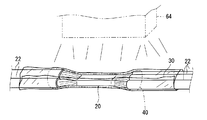
- the water-stopping agent 40 when a photocurable resin is used as the water-stopping agent 40, the water-stopping agent 40 is supplied to the intermediate splice portion 20 and wound around the protective sheet 30, and then the water-stopping agent 40 is irradiated with light.
- the liquid medicine 40 can be cured relatively quickly. For this reason, it is not necessary to stand for a long time until the water-stopping agent 40 is cured, and after the water-stopping agent 40 is supplied and the protective sheet 30 is wound, the water-stopping intermediate splice portion 10 is set relatively early. Handling such as transporting to the next process can be performed.
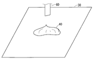
- a protective sheet 30 having a size that can cover at least the intermediate splice 20 is spread, and a water-stopping agent 40 is supplied onto the protective sheet 30. It is preferable that the water stopping agent 40 is discharged to the central portion of the protective sheet 30. It is preferable that a fixed amount of the water-stopping agent 40 is discharged from a nozzle 60 of a discharge device that can discharge a fixed amount.
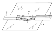
- the intermediate splice unit 20 is placed on the water-stopping agent 40 discharged on the protective sheet 30.
- the water stopping agent 40 is supplied to the intermediate splice portion 20 of the electric wire 22 (step (a)).
- the water stop agent 40 may be supplied to the intermediate splice unit 20.
- the intermediate splice unit 20 may be placed on the protective sheet 30, and the water stopping agent 40 may be discharged from the nozzle 60 thereon.
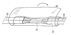
- the protective sheet 30 covers the intermediate splice portion 20 and the water stop agent 40 supplied thereto (step (b)).
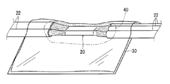
- the protective sheet 30 is folded in half so that the intermediate part of the protective sheet 30 is wound around the intermediate splice part 20 and the water-stopping agent 40 and both ends are directed outward. It is pulled out in a superimposed state. Note that the overlapping portion of the protective sheet 30 is maintained in a state of self-adhesion.
- the protective sheet 30 around the intermediate splice portion 20 and the waterstop agent 40 while applying a force from the periphery.
- the water-stopping agent 40 locally present around the outer periphery of the intermediate splice part 20 is extruded and travels between the outer peripheral part of the intermediate splice part 20 and the protective sheet 30, and This is because the entire periphery is covered and the water-stopping agent 40 is also extruded between the core portions 26 and between the electric wires 22 to fill the gaps.
- the overlapping portion of the protective sheet 30 is squeezed so that the water stopping agent 40 of the overlapping portion is directed to the intermediate splice portion 20. It is preferable to push in.
- the overlapping part of the protective sheet 30 is placed on the plate, and the round bar member 62 is placed at the edge of the overlapping part in a state where the overlapping part is sandwiched between the plate and the round bar member 62.
- the water-stopping agent 40 is pushed toward the intermediate splice part 20 so as to be squeezed up by being moved toward the intermediate splice part 20. At this time, the mixed bubbles can be escaped from the water-stopping agent 40. Thereby, the supplied water-stopping agent 40 covers the intermediate splice part 20 around more reliably.
- the overlapping portion of the protective sheet 30 is wound around the intermediate splice part 20 and the water stop agent 40 as shown in FIG. It is maintained by the self-adhesiveness of the protective sheet 30 in the wound state.
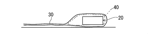
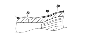
- FIG. 7 shows a state immediately after the protective sheet 30 is wound, and FIG. 13 shows a state where the water-stopping agent 40 has been cured.
- the water-stopping agent 40 supplied to the intermediate splice part 20 contracts until it hardens, or tries to enter between the exposed core part 26 or the electric wire 22. For this reason, the surface of the water blocking agent 40 may be recessed.
- the protective sheet 30 deforms unevenly following the change in the shape of the surface of the water blocking agent 40 (see the two-dot chain line in FIG. 13). Thereby, the adhesiveness of the surface of the water stop agent 40 and the protection sheet 30 is maintained, and generation
- the surface of the water-stop agent 40 and the protective sheet 30 are deformed by deforming the protective sheet 30 following the deformation of the surface of the water-stop agent 40.
- the water-stopping agent 40 supplied to the intermediate splice portion 20 and its A gap between the protective sheet 30 covering the water stop agent 40 can be suppressed.
- the protective sheet 30 has self-adhesiveness, when the protective sheet 30 is covered around the intermediate splice 20 and the water-stopping agent 40, the covered state is maintained, so that the workability is excellent.
- the protective sheet 30 is wound around the intermediate splice portion 20 and the water-stopping agent 40 while applying a force from around, the water-stopping agent is dispersed around the water-stopping agent 40 and easily enters between the electric wires 22. Therefore, water stop can be performed more reliably.
- the overlapped portion of the protective sheet 30 is pressed and the water-stopping agent 40 in the overlapped portion is pushed toward the intermediate splice portion 20, so Since the amount of the water-stopping agent 40 is concentrated around the intermediate splice part 20 and easily enters between the electric wires 22, the water-stopping can be performed more reliably from this point.
- FIG. 14 is a plan view showing the winding device 102
- FIG. 15 is a side view showing the winding device 102.
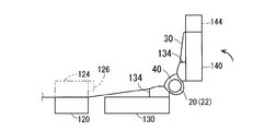
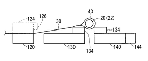
- the winding device 102 includes a sheet supply unit 110, a relay fixing table 120, a fixing table 130, a movable table 140, and an electric wire fixing unit 160.
- the sheet supply unit 110, the relay fixed table 120, the fixed table 130, and the movable table 140 are arranged on the base 104 in a straight line in this order.
- the relay fixing table 120, the fixed table 130, and the movable table 140 are disposed at the same height position, and the protective sheet 30 supplied from the sheet supply unit 110 is also as high as the fixed table 130 as much as possible.
- the protective sheet 30 can be supplied at the position.
- the fixed table 130 is formed in a long plate shape having a length dimension larger than the width dimension of the protective sheet 30, and is fixed on the base 104 in a substantially horizontal posture via the leg portion 138.
- the sheet supply unit 110 is provided at a position away from the long side on one side of the fixed table 130.
- a pair of support plates 114 are erected on a movable unit 112, and a support shaft unit 116 is supported between the pair of support plates 114 in a substantially horizontal posture.
- the protection shaft roll 116 is supported so that the protection sheet 30 can be pulled out by the support shaft part 116 being inserted through the protection sheet roll 38 in which the protection sheet 30 is wound and accommodated.
- the sheet supply unit 110 is supported by a slider 118 so as to be movable toward and away from the fixed table 130.
- a coil spring 119 as an urging member is attached in a tensioned state between the extending portion 119 a extending outward from the base 104 and the movable portion 112.
- the coil spring 119 urges the protective sheet roll 38 away from the fixed table 130.
- the relay fixing table 120 is supported on the base 104 by the leg portion 128 between the sheet supply unit 110 and the fixing table 130.
- an opposing clamping member 124 is detachably disposed on the relay fixing table 120.
- the opposing clamping member 124 has a protective sheet 30 between the relay fixing table 120 and the opposing clamping member 124 by its own weight or a clamping force utilizing a magnetic force between itself and the relay fixing table 120. Can be supported.
- a gap is provided between the relay fixing table 120 and the fixing table 130, and it is preferable that the protective sheet 30 can be easily cut between the gaps.
- the movable table 140 is supported by the fixed table 130 via a hinge part 136, and is set in a horizontal state with respect to the fixed table 130 and supported between the fixed table 130 and the movable table 140.
- the posture can be changed between a superposition posture rotated about an axis and opposed to the upper side of the fixed table 130.
- the leg 148 below the movable table 140 has a role of supporting the movable table 140 in the set posture in a mounting manner.
- the hinge part 136 is located in the both ends between the fixed table 130 and the movable table 140, The intermediate part is opened in slit shape.
- a clamping member 144 is detachably attached to the side surface of the movable table 140 opposite to the fixed table 130.
- the sandwiching member 144 can support the protective sheet 30 by sandwiching the protective sheet 30 between the movable table 140 and the sandwiching member 144 by a sandwiching force using magnetic force or the like with respect to the movable table 140.
- a long elastic member 134 (for example, sponge) is fixed to the side of the upper surface of the fixed table 130 near the movable table 140 and the side of the movable table 140 near the fixed table 130 with a double-sided tape or the like. Has been.
- an electric wire support portion 160 that supports the electric wires 22 that support the outer electric wires 22 of the intermediate splice portion 20 is provided at an outward extension portion between the fixed table 130 and the movable table 140.
- a U-shaped jig that opens to the upper end portion is used as the wire support portion 160.
- the protective sheet 30 is pulled out from the sheet supply unit 110 and placed on the relay fixed table 120, the fixed table 130, and the movable table 140.
- the protective sheet 30 is sandwiched and fixed between the relay fixing table 120 and the opposing sandwiching member 124, and the protective sheet 30 is sandwiched and fixed between the movable table 140 and the sandwiching member 144.
- the protective sheet 30 is pulled between the relay fixed table 120 and the movable table 140.
- the tension state and the force by which the long elastic member 134 lifts the protection sheet 30 upward are combined, so that the protection sheet 30 is more reliably pulled (see FIGS. 16 and 17).
- the water stopping agent 40 is supplied onto the protective sheet 30, and the intermediate splice 20 is placed (see FIG. 18).
- the electric wires 22 at both ends of the intermediate splice portion 20 are supported at a fixed position by the electric wire support portion 160.
- the movable table 140 in the set posture is rotated so as to be raised toward the fixed table 130 side.
- the protective sheet 30 is wound around the intermediate splice part 20 and the water-stopping agent 40 in a folded manner while the electric wire 22 is maintained at a fixed position in the vicinity of the axial extension of the hinge part 136 (see FIGS. 19 and 20). ).
- the protective sheet 30 is pulled as described above, the protective sheet 30 is pressed against the intermediate splice portion 20 from the outer periphery.
- both ends of the protective sheet 30 are supported as described above, and the protective sheet 30 is maintained at a fixed position by the electric wire support part 160 while the protective sheet 30 has the intermediate splice part 20 and the water stopping agent 40. Since it is wound around, the protective sheet 30 is wound around the intermediate splice part 20 and the water-stopping agent 40 in a state where tension is applied to the protective sheet 30.
- the movable table 140 is rotated to the overlapping posture, the extended portion of the protective sheet 30 is sandwiched between the pair of long elastic members 134. Thereby, the protection sheet 30 is wound around the intermediate splice part 20 and the water-stopping agent 40 in a folded shape.
- water stop intermediate splice 10 can be manufactured in the same manner as described above.
- the protective sheet 30 can be wound around the intermediate splice part 20 and the water-stopping agent 40 while applying a force from the surroundings relatively easily.
- FIG. 22 is a plan view showing the winding device 202
- FIG. 23 is a side view showing the winding device 202.
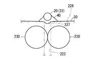
- the winding device 202 includes a sheet supply unit 210, a base 220, a pair of rollers 230, and an electric wire moving mechanism unit 240.
- the base 220 has a pair of side plate portions 222 and a top plate portion 226.
- the top plate portion 226 is formed with slit-shaped openings 227 that penetrate the both ends of the top plate portion 226.
- side grooves 223 (here, bottomed grooves) that open upward are formed so as to be continuous with both ends of the opening 227.
- the opening 227 and the side groove 223 are formed to have a width that allows the intermediate splice portion 20 and the plurality of electric wires 22 to be inserted therethrough.
- a sheet supply unit 210 is provided on one side of the base 220.
- the sheet supply unit 210 is configured to be able to support a protective sheet roll 38 around which the protective sheet 30 is wound and accommodated, and the protective sheet 30 supplied from the protective sheet roll is pulled out in a direction substantially orthogonal to the opening 227. It can be placed on the top plate 226.
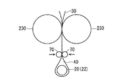
- the pair of rollers 230 is a member in which an elastic roller member 234 such as a sponge is disposed around the shaft portion 232, and is provided so as to sandwich a space connecting the pair of side grooves 223 between the pair of side plate portions 222. Yes. Both end portions of the shaft portion 232 are rotatably supported by inner surface portions of the pair of side plate portions 222. Further, the pair of rollers 230 are arranged so as to contact each other. When the electric wires 22 at both ends of the intermediate splice portion 20 are moved downward along the pair of side grooves 223, the intermediate splice portion 20 is sandwiched by the pair of rollers 230, and the pair of rollers While rotating 230, it moves downward.
- an elastic roller member 234 such as a sponge
- the pair of rollers 230 are not necessarily in contact with each other. Further, the pair of rollers 230 only need to have elasticity such that the surface portion is elastically deformed according to the peripheral shape of the intermediate splice portion 20 and a force can be applied to the peripheral portion.
- the electric wire moving mechanism part 240 has an electric wire gripping part 242, an intervening support part 244, and a driving part 248.
- the intervening support portion 244 is formed in a substantially L-shaped member, and has one end portion disposed in a posture along the side groove 223 and the other end portion on the outer side of the base 220 (sheet supply portion).
- the outer side of the side plate portion 222 is supported by the guide member 245 so as to be movable in a posture that extends outward (toward the outer side opposite to 210).
- the electric wire gripping part 242 has a pair of gripping claws 242a, and is configured to be able to grip and release the electric wire 22 by a so-called electromagnetic chuck or the like using an electromagnetic action.
- the electric wire gripping part 242 is attached to one end of the interposition support part 244, and as the electric wire gripping part 242 moves up and down, moves up and down along the side groove 223 on the outer side of the side groove 223. It is possible.
- the driving unit 248 is configured by a linear actuator such as an air cylinder or a hydraulic cylinder attached to the side of the base 104 (the side opposite to the sheet supply unit 210).
- This drive part 248 has a rod part 248 a that can be driven back and forth downward, and the rod part 248 a is connected to the other end of the interposition support part 244.
- the electric wire gripping part 242 and the intervening support part 244 are driven up and down by driving of the driving part 248.
- the operations of the electric wire gripping part 242 and the driving part 248 may be operated by a separately provided operation switch, or may be controlled by a control controller or the like.
- the protective sheet 30 is pulled out from the sheet supply unit 210 and cut into a predetermined length, and then the cut protective sheet 30 is placed on the top plate part 226. At this time, the opening 227 is disposed in the intermediate portion of the protective sheet 30. Subsequently, the water stopping agent 40 is supplied onto the protective sheet 30 at the position of the opening 227, and the intermediate splice unit 20 is placed (see FIG. 24).
- the electric wire 22 is grasped between the pair of grasping claws 242a by driving the electric wire grasping portion 242 at the outward extension position of the opening 227. Thereafter, the electric wire 22 is moved downward along the lateral groove 223 by driving of the driving unit 248. Then, the intermediate splice portion 20 is sandwiched between the pair of rollers 230 while being folded in two by the protective sheet 30 (see FIG. 25). At this time, the elastic roller member 234 sandwiches the intermediate splice part 20, the water stopping agent 40 and the protective sheet 30 while elastically deforming according to the shape of the peripheral part of the intermediate splice part 20. Accordingly, the protective sheet 30 is wound around the intermediate splice part 20 and the water-stopping agent 40 while a force is applied from around.
- water stop intermediate splice 10 can be manufactured in the same manner as described above.
- the protective sheet 30 can be wound around the intermediate splice part 20 and the water-stopping agent 40 while applying a force from the surroundings relatively easily.
- the intermediate splice unit 20 may be passed between the pair of rollers 230 in a state where both ends of the protective sheet 30 are pulled with a certain amount of force.
- each structure demonstrated by said each embodiment and each modification can be suitably combined unless it mutually contradicts.
Landscapes
- Engineering & Computer Science (AREA)
- Manufacturing & Machinery (AREA)
- Cable Accessories (AREA)
- Processing Of Terminals (AREA)
- Connections Effected By Soldering, Adhesion, Or Permanent Deformation (AREA)
- Manufacturing Of Electric Cables (AREA)
Abstract
Description
まず、電線の止水中間スプライス部について説明する。図1は電線の止水中間スプライス部10を示す斜視図である。この電線の止水中間スプライス部10は、電線の中間スプライス部20と、止水剤40と、保護シート30とを備えている。
以下、電線の止水中間スプライス部10の製造方法について説明する。なお、以下では、止水剤40がUV硬化性樹脂であり、保護シート30は、適切な柔軟性、自己密着性、伸縮性、UV透過性等を有するものとして説明する。もっとも、それらの性質は、製造上問題なければ、必ずしも必須ではない。
上記製造方法のうち周りから力を加えつつ保護シート30を中間スプライス部20及び止水剤40周りに巻付ける工程に着目して説明する。
巻付け方法例2では、一対のローラで挟込みつつ、保護シート30を中間スプライス部20及び止水剤40に巻付ける例について説明する。
Claims (13)
- (a)電線の中間スプライス部に止水剤を供給する工程と、
(b)保護シートで前記中間スプライス部に供給された止水剤を覆う工程と、
(c)前記止水剤の表面の変形に追随して前記保護シートを変形させることにより前記止水剤の表面と前記保護シートとを密着させた状態に維持しつつ、前記止水剤を硬化させる工程と、
とを備える電線の止水中間スプライス部の製造方法。 - 請求項1記載の電線の止水中間スプライス部の製造方法であって、
前記保護シートとして、前記中間スプライス部に供給された止水剤の表面の変形に追随して変形可能な柔軟性を有する保護シートを用いる、止水中間スプライス部の製造方法。 - 請求項1記載の電線の止水中間スプライス部の製造方法であって、
前記保護シートとして、自己密着性を持つ保護シートを用いる、止水中間スプライス部の製造方法。 - 請求項1記載の電線の止水中間スプライス部の製造方法であって、
前記止水剤は光硬化性を有し、
前記保護シートは前記止水剤を硬化させる光を透過可能であり、
前記工程(c)で前記止水剤を硬化させる光を照射して前記止水剤を硬化させる、電線の止水中間スプライス部の製造方法。 - 請求項1記載の電線の止水中間スプライス部の製造方法であって、
前記止水剤は、熱硬化性、湿気硬化性、カチオン重合硬化性、アニオン重合硬化性、付加反応硬化性のうちの少なくとも1つが付与された光硬化性樹脂である、電線の止水中間スプライス部の製造方法。 - 請求項1記載の電線の止水中間スプライス部の製造方法であって、
前記工程(b)において、周りから力を加えつつ前記保護シートを前記中間スプライス部に供給された止水剤に巻付ける、電線の止水中間スプライス部の製造方法。 - 請求項6記載の電線の止水中間スプライス部の製造方法であって、
前記保護シートに張力を加えた状態で前記保護シートを前記中間スプライス部に供給された止水剤に巻付ける、電線の止水中間スプライス部の製造方法。 - 請求項6記載の電線の止水中間スプライス部の製造方法であって、
一対のローラで挟込みつつ、前記保護シートを前記中間スプライス部に供給された止水剤に巻付ける、電線の止水中間スプライス部の製造方法。 - 請求項1記載の電線の止水中間スプライス部の製造方法であって、
前記工程(b)の途中において、前記保護シートが前記中間スプライス部に供給された止水剤に巻付けられると共に外方に向けて重ね合された状態で引出され、前記保護シートの重ね合せ部分がしごかれるようにして当該重ね合せ部分の止水剤が中間スプライス部に向けて押込まれる、電線の止水中間スプライス部の製造方法。 - 電線の中間スプライス部と、
前記中間スプライス部に供給されて硬化した止水剤と、
前記中間スプライス部に供給された止水剤の表面の変形に追随して変形可能な柔軟性を有し、前記止水剤の表面に密着した状態で前記止水剤を覆う保護シートと、
を備える電線の止水中間スプライス部。 - 請求項10記載の電線の止水中間スプライス部であって、
前記保護シートは自己密着性を持つ保護シートである、電線の止水中間スプライス部。 - 請求項10記載の電線の止水中間スプライス部であって、
前記止水剤は光硬化性を有し、
前記保護シートは前記止水剤を硬化させる光を透過可能である、電線の止水中間スプライス部。 - 請求項10記載の電線の止水中間スプライス部であって、
前記止水剤は、熱硬化性、湿気硬化性、カチオン重合硬化性、アニオン重合硬化性、付加反応硬化性のうちの少なくとも1つが付与された光硬化性樹脂である、電線の止水中間スプライス部。
Priority Applications (3)
| Application Number | Priority Date | Filing Date | Title |
|---|---|---|---|
| DE112011103304.4T DE112011103304B4 (de) | 2010-09-30 | 2011-06-07 | Verfahren zum Herstellen eines wasserdichten zwischenliegenden gespleißten Abschnitts von Drähten und wasserdichte zwischenliegende gespleißte Einheit von Drähten |
| CN201180047428.6A CN103155318B (zh) | 2010-09-30 | 2011-06-07 | 电线的止水中间绞接部的制造方法和电线的止水中间绞接部 |
| US13/816,782 US9407051B2 (en) | 2010-09-30 | 2011-06-07 | Method of manufacturing waterproof intermediate spliced portion of wires and waterproof intermediate unit of wires |
Applications Claiming Priority (2)
| Application Number | Priority Date | Filing Date | Title |
|---|---|---|---|
| JP2010-222003 | 2010-09-30 | ||
| JP2010222003A JP5418457B2 (ja) | 2010-09-30 | 2010-09-30 | 電線の止水中間スプライス部の製造方法及び電線の止水中間スプライス部 |
Publications (1)
| Publication Number | Publication Date |
|---|---|
| WO2012042979A1 true WO2012042979A1 (ja) | 2012-04-05 |
Family
ID=45892460
Family Applications (1)
| Application Number | Title | Priority Date | Filing Date |
|---|---|---|---|
| PCT/JP2011/063068 Ceased WO2012042979A1 (ja) | 2010-09-30 | 2011-06-07 | 電線の止水中間スプライス部の製造方法及び電線の止水中間スプライス部 |
Country Status (5)
| Country | Link |
|---|---|
| US (1) | US9407051B2 (ja) |
| JP (1) | JP5418457B2 (ja) |
| CN (1) | CN103155318B (ja) |
| DE (1) | DE112011103304B4 (ja) |
| WO (1) | WO2012042979A1 (ja) |
Cited By (8)
| Publication number | Priority date | Publication date | Assignee | Title |
|---|---|---|---|---|
| WO2013011846A1 (ja) * | 2011-07-19 | 2013-01-24 | 株式会社オートネットワーク技術研究所 | 防食剤、端子付き被覆電線およびワイヤーハーネス |
| WO2013011847A1 (ja) * | 2011-07-19 | 2013-01-24 | 株式会社オートネットワーク技術研究所 | 防食剤、端子付き被覆電線およびワイヤーハーネス |
| EP2731203A1 (de) * | 2012-08-29 | 2014-05-14 | Nexans | Verfahren zum feuchtigkeitsdichten Abdecken einer Verbindungsstelle zwischen einem elektrischen Leiter und einem Kontaktelement |
| US20170338005A1 (en) * | 2014-11-28 | 2017-11-23 | Autonetworks Technologies, Ltd. | Wiring harness |
| US20220028581A1 (en) * | 2019-01-30 | 2022-01-27 | Autonetworks Technologies, Ltd. | Insulated electric wire, wire harness, and insulated electric wire production method |
| US20220157491A1 (en) * | 2019-01-30 | 2022-05-19 | Autonetworks Technologies, Ltd. | Insulated electric wire and wire harness |
| US20220165453A1 (en) * | 2019-01-30 | 2022-05-26 | Autonetworks Technologies, Ltd. | Insulated electric wire and wire harness |
| US11887757B2 (en) | 2019-01-30 | 2024-01-30 | Autonetworks Technologies, Ltd. | Insulated electric wire and wire harness |
Families Citing this family (16)
| Publication number | Priority date | Publication date | Assignee | Title |
|---|---|---|---|---|
| JP2013251166A (ja) * | 2012-06-01 | 2013-12-12 | Auto Network Gijutsu Kenkyusho:Kk | ワイヤーハーネス及びその製造方法 |
| JP2014116196A (ja) * | 2012-12-10 | 2014-06-26 | Auto Network Gijutsu Kenkyusho:Kk | ワイヤーハーネス及びその製造方法 |
| DE102013201167A1 (de) * | 2013-01-24 | 2014-08-07 | Elringklinger Ag | Verfahren zum Herstellen einer elektrisch leitenden Verbindung zwischen einer elektrischen Leitung und einem elektrisch leitenden Bauteil und nach dem Verfahren hergestellte Baugruppe |
| JP5924288B2 (ja) * | 2013-02-15 | 2016-05-25 | 住友電装株式会社 | 電線スプライス部の止水方法及び電線群整列装置 |
| DE102013217177B4 (de) * | 2013-08-28 | 2016-08-25 | Volkswagen Aktiengesellschaft | Verfahren zur elektrischen Isolation eines Splices |
| JP5999052B2 (ja) * | 2013-08-30 | 2016-09-28 | 住友電装株式会社 | 止水構造付電線束の製造装置 |
| JP6123699B2 (ja) * | 2014-02-20 | 2017-05-10 | 住友電装株式会社 | シート巻付装置及びスプライス部を含む電線モジュールの製造方法 |
| JP6128006B2 (ja) * | 2014-02-20 | 2017-05-17 | 住友電装株式会社 | 硬化用光照射装置及びスプライス部を含む電線モジュールの製造方法 |
| JP6070604B2 (ja) * | 2014-03-05 | 2017-02-01 | 住友電装株式会社 | シート取付装置、電線加工装置及びスプライス部を含む電線モジュールの製造方法 |
| JP2016163509A (ja) | 2015-03-05 | 2016-09-05 | 住友電装株式会社 | ワイヤハーネスの防水構造 |
| JP6439742B2 (ja) | 2016-04-27 | 2018-12-19 | 株式会社オートネットワーク技術研究所 | ワイヤーハーネス |
| JP6439743B2 (ja) | 2016-04-27 | 2018-12-19 | 株式会社オートネットワーク技術研究所 | ワイヤーハーネス |
| DE102017104865B3 (de) | 2017-03-08 | 2018-03-22 | Lisa Dräxlmaier GmbH | Vorrichtung und verfahren zum automatisierten abdichten einer verbindungsstelle von miteinander verschweissten elektrischen leitungen |
| DE102018101427B4 (de) * | 2018-01-23 | 2019-10-10 | Lisa Dräxlmaier GmbH | System zum automatisierten Abdichten einer Verbindungsstelle von miteinander verbundenen elektrischen Leitungen |
| JP7052489B2 (ja) * | 2018-03-30 | 2022-04-12 | 株式会社オートネットワーク技術研究所 | 端子付き電線およびワイヤーハーネス |
| JP7390132B2 (ja) * | 2019-08-21 | 2023-12-01 | 株式会社オートネットワーク技術研究所 | ワイヤーハーネス |
Citations (7)
| Publication number | Priority date | Publication date | Assignee | Title |
|---|---|---|---|---|
| JPH11196521A (ja) * | 1997-12-26 | 1999-07-21 | Sumitomo Wiring Syst Ltd | ワイヤーハーネス内の連通空間の閉塞方法および該閉塞方法に用いる作業装置 |
| JP2002369328A (ja) * | 2001-06-08 | 2002-12-20 | Sumitomo Wiring Syst Ltd | 電線の中間防水接続方法および中間防水接続構造 |
| WO2005104302A1 (ja) * | 2004-04-26 | 2005-11-03 | Sumitomo Wiring Systems, Ltd. | 電線接続部の防水構造および防水方法 |
| JP2008123712A (ja) * | 2006-11-08 | 2008-05-29 | Auto Network Gijutsu Kenkyusho:Kk | 電線の止水処理方法および止水構造 |
| JP2009038953A (ja) * | 2007-07-06 | 2009-02-19 | Furukawa Denko Sangyo Densen Kk | ケーブル端末の防水処理方法、防水処理構造および防水処理用キット |
| JP2009130981A (ja) * | 2007-11-20 | 2009-06-11 | Sumitomo Wiring Syst Ltd | スプライス部の防水方法および防水スプライス部を備えたワイヤハーネス |
| JP2010153344A (ja) * | 2008-11-25 | 2010-07-08 | Sumitomo Wiring Syst Ltd | シールド線の端末止水方法および端末止水部を備えたシールド線 |
Family Cites Families (19)
| Publication number | Priority date | Publication date | Assignee | Title |
|---|---|---|---|---|
| GB1081675A (en) * | 1964-01-09 | 1967-08-31 | Prec Rubbers Ltd | Improvements relating to rubber grommets, bushes and the like |
| US3393796A (en) * | 1965-12-08 | 1968-07-23 | Minnesota Mining & Mfg | Packaged article and method of packaging |
| US3507977A (en) * | 1968-12-04 | 1970-04-21 | Superior Continental Corp | Connectors filled with polyethylene grease |
| US3879575A (en) * | 1974-02-21 | 1975-04-22 | Bell Telephone Labor Inc | Encapsulating compound and closure |
| US4648919A (en) * | 1984-09-18 | 1987-03-10 | Raychem Corp. | Protection of cable splice |
| GB8604501D0 (en) * | 1986-02-24 | 1986-04-03 | Raychem Sa Nv | Cable splice case |
| GB8704232D0 (en) * | 1987-02-24 | 1987-04-01 | Raychem Sa Nv | Electrical device |
| US4818310A (en) * | 1987-05-05 | 1989-04-04 | Bell South Corporation | Pressurized cable splice closure apparatus and method |
| US4888070A (en) * | 1987-12-01 | 1989-12-19 | Raychem Corporation | Environmental sealing of a substrate |
| US4849580A (en) * | 1988-02-11 | 1989-07-18 | Minnesota Mining And Manufacturing Company | Environmental protection closure for wire splices; and method |
| US4962286A (en) * | 1988-10-06 | 1990-10-09 | Raychem Corporation | Environmental control, liner for splice enclosure |
| JPH04111110A (ja) | 1990-08-31 | 1992-04-13 | Nec Corp | 情報入力用キーボード |
| JP2936795B2 (ja) * | 1991-05-09 | 1999-08-23 | 住友電装株式会社 | 電線接続部の防水加工方法 |
| US5399810A (en) * | 1992-11-03 | 1995-03-21 | Three Bond Co., Ltd. | Means for coating connecting portions of electrical wires |
| JP2894581B2 (ja) * | 1993-05-24 | 1999-05-24 | 矢崎総業株式会社 | ワイヤーハーネスの防水構造 |
| US6719462B2 (en) * | 2001-06-20 | 2004-04-13 | Chemque, Inc. | Splice protection system |
| CN101300645B (zh) * | 2005-11-02 | 2011-12-28 | 株式会社自动网络技术研究所 | 车载电线类的止水处理方法 |
| JP2009136039A (ja) * | 2007-11-28 | 2009-06-18 | Sumitomo Wiring Syst Ltd | スプライス部の防水方法および防水スプライス部を備えたワイヤハーネス |
| JP5402225B2 (ja) | 2008-11-26 | 2014-01-29 | Jsr株式会社 | 電線止水材用キット、電線止水材、止水部材、止水処理された電線および止水処理方法 |
-
2010
- 2010-09-30 JP JP2010222003A patent/JP5418457B2/ja active Active
-
2011
- 2011-06-07 DE DE112011103304.4T patent/DE112011103304B4/de active Active
- 2011-06-07 US US13/816,782 patent/US9407051B2/en active Active
- 2011-06-07 CN CN201180047428.6A patent/CN103155318B/zh active Active
- 2011-06-07 WO PCT/JP2011/063068 patent/WO2012042979A1/ja not_active Ceased
Patent Citations (7)
| Publication number | Priority date | Publication date | Assignee | Title |
|---|---|---|---|---|
| JPH11196521A (ja) * | 1997-12-26 | 1999-07-21 | Sumitomo Wiring Syst Ltd | ワイヤーハーネス内の連通空間の閉塞方法および該閉塞方法に用いる作業装置 |
| JP2002369328A (ja) * | 2001-06-08 | 2002-12-20 | Sumitomo Wiring Syst Ltd | 電線の中間防水接続方法および中間防水接続構造 |
| WO2005104302A1 (ja) * | 2004-04-26 | 2005-11-03 | Sumitomo Wiring Systems, Ltd. | 電線接続部の防水構造および防水方法 |
| JP2008123712A (ja) * | 2006-11-08 | 2008-05-29 | Auto Network Gijutsu Kenkyusho:Kk | 電線の止水処理方法および止水構造 |
| JP2009038953A (ja) * | 2007-07-06 | 2009-02-19 | Furukawa Denko Sangyo Densen Kk | ケーブル端末の防水処理方法、防水処理構造および防水処理用キット |
| JP2009130981A (ja) * | 2007-11-20 | 2009-06-11 | Sumitomo Wiring Syst Ltd | スプライス部の防水方法および防水スプライス部を備えたワイヤハーネス |
| JP2010153344A (ja) * | 2008-11-25 | 2010-07-08 | Sumitomo Wiring Syst Ltd | シールド線の端末止水方法および端末止水部を備えたシールド線 |
Cited By (13)
| Publication number | Priority date | Publication date | Assignee | Title |
|---|---|---|---|---|
| WO2013011846A1 (ja) * | 2011-07-19 | 2013-01-24 | 株式会社オートネットワーク技術研究所 | 防食剤、端子付き被覆電線およびワイヤーハーネス |
| WO2013011847A1 (ja) * | 2011-07-19 | 2013-01-24 | 株式会社オートネットワーク技術研究所 | 防食剤、端子付き被覆電線およびワイヤーハーネス |
| EP2731203A1 (de) * | 2012-08-29 | 2014-05-14 | Nexans | Verfahren zum feuchtigkeitsdichten Abdecken einer Verbindungsstelle zwischen einem elektrischen Leiter und einem Kontaktelement |
| US20170338005A1 (en) * | 2014-11-28 | 2017-11-23 | Autonetworks Technologies, Ltd. | Wiring harness |
| US10290396B2 (en) * | 2014-11-28 | 2019-05-14 | Autonetworks Technologies, Ltd. | Wiring harness having waterproofing agent with reactive adhesive |
| US20220028581A1 (en) * | 2019-01-30 | 2022-01-27 | Autonetworks Technologies, Ltd. | Insulated electric wire, wire harness, and insulated electric wire production method |
| US20220157491A1 (en) * | 2019-01-30 | 2022-05-19 | Autonetworks Technologies, Ltd. | Insulated electric wire and wire harness |
| US20220165453A1 (en) * | 2019-01-30 | 2022-05-26 | Autonetworks Technologies, Ltd. | Insulated electric wire and wire harness |
| US11887757B2 (en) | 2019-01-30 | 2024-01-30 | Autonetworks Technologies, Ltd. | Insulated electric wire and wire harness |
| US11887758B2 (en) * | 2019-01-30 | 2024-01-30 | Autonetworks Technologies, Ltd. | Wire harness and insulated electric wire thereof having water-stopping agent |
| US11887759B2 (en) | 2019-01-30 | 2024-01-30 | Autonetworks Technologies, Ltd. | Insulated electric wire with water-stopping agent, wire harness, and insulated electric wire production method |
| US11908598B2 (en) * | 2019-01-30 | 2024-02-20 | Autonetworks Technologies, Ltd. | Insulated electric wire and harness with water-stopping agent and wire harness |
| US12249444B2 (en) | 2019-01-30 | 2025-03-11 | Autonetworks Technologies, Ltd. | Insulated electric wire and wire harness |
Also Published As
| Publication number | Publication date |
|---|---|
| CN103155318B (zh) | 2016-10-19 |
| JP2012080633A (ja) | 2012-04-19 |
| US20130175069A1 (en) | 2013-07-11 |
| DE112011103304T5 (de) | 2013-07-18 |
| US9407051B2 (en) | 2016-08-02 |
| JP5418457B2 (ja) | 2014-02-19 |
| CN103155318A (zh) | 2013-06-12 |
| DE112011103304B4 (de) | 2017-03-09 |
Similar Documents
| Publication | Publication Date | Title |
|---|---|---|
| JP5418457B2 (ja) | 電線の止水中間スプライス部の製造方法及び電線の止水中間スプライス部 | |
| JP2012248527A (ja) | ワイヤーハーネス及びその製造方法 | |
| US7509009B2 (en) | Optical fiber structure and method of manufacturing same | |
| JP5924288B2 (ja) | 電線スプライス部の止水方法及び電線群整列装置 | |
| WO2011065310A1 (ja) | ワイヤーハーネスの製造方法、及びワイヤーハーネス | |
| JP6172127B2 (ja) | ワイヤーハーネス | |
| JP5482140B2 (ja) | ワイヤーハーネスの製造方法、及びワイヤーハーネス | |
| TWI322129B (ja) | ||
| JP2016091629A (ja) | ワイヤーハーネス | |
| JP7405289B2 (ja) | 絶縁電線およびワイヤーハーネス | |
| JP2013251166A (ja) | ワイヤーハーネス及びその製造方法 | |
| JP5526731B2 (ja) | ワイヤーハーネスの製造方法、及びワイヤーハーネス | |
| CN1907829B (zh) | 用胶带粘接带材接头的方法及胶带施放装置 | |
| CN107207181B (zh) | 卷筒体、薄膜连结体、薄膜卷装体及薄膜连结体的制造方法 | |
| JP6693161B2 (ja) | フィルム連結体、フィルム巻装体、リール体、及びフィルム連結体の製造方法 | |
| JP5999052B2 (ja) | 止水構造付電線束の製造装置 | |
| JP6070604B2 (ja) | シート取付装置、電線加工装置及びスプライス部を含む電線モジュールの製造方法 | |
| JP6123699B2 (ja) | シート巻付装置及びスプライス部を含む電線モジュールの製造方法 | |
| CN114735311A (zh) | 一种起膜回膜方法 | |
| JP6128006B2 (ja) | 硬化用光照射装置及びスプライス部を含む電線モジュールの製造方法 | |
| EP4300741A1 (en) | Covering tool and covering method | |
| HK1241838B (zh) | 卷筒体、薄膜连结体、薄膜卷装体及薄膜连结体的制造方法 | |
| JP2006126376A (ja) | 光ファイバ構造体及びそれを用いたファンアウト光ファイバ構造体並びにそれらの作製方法 | |
| JP2025011855A (ja) | テープ端末貼付け装置 | |
| RU2007110397A (ru) | Способ и устройство для ремонта трубопроводов путем бандажирования |
Legal Events
| Date | Code | Title | Description |
|---|---|---|---|
| WWE | Wipo information: entry into national phase |
Ref document number: 201180047428.6 Country of ref document: CN |
|
| 121 | Ep: the epo has been informed by wipo that ep was designated in this application |
Ref document number: 11828540 Country of ref document: EP Kind code of ref document: A1 |
|
| WWE | Wipo information: entry into national phase |
Ref document number: 13816782 Country of ref document: US |
|
| WWE | Wipo information: entry into national phase |
Ref document number: 112011103304 Country of ref document: DE Ref document number: 1120111033044 Country of ref document: DE |
|
| 122 | Ep: pct application non-entry in european phase |
Ref document number: 11828540 Country of ref document: EP Kind code of ref document: A1 |