WO2012033174A1 - Appareil d'éclairage, appareil de projection, et appareil d'affichage vidéo par projection - Google Patents
Appareil d'éclairage, appareil de projection, et appareil d'affichage vidéo par projection Download PDFInfo
- Publication number
- WO2012033174A1 WO2012033174A1 PCT/JP2011/070519 JP2011070519W WO2012033174A1 WO 2012033174 A1 WO2012033174 A1 WO 2012033174A1 JP 2011070519 W JP2011070519 W JP 2011070519W WO 2012033174 A1 WO2012033174 A1 WO 2012033174A1
- Authority
- WO
- WIPO (PCT)
- Prior art keywords
- light
- coherent
- recording medium
- coherent light
- hologram recording
- Prior art date
Links
- 238000005286 illumination Methods 0.000 title claims abstract description 68
- 230000001427 coherent effect Effects 0.000 claims abstract description 267
- 230000003287 optical effect Effects 0.000 claims abstract description 119
- 230000001678 irradiating effect Effects 0.000 claims description 6
- 230000000737 periodic effect Effects 0.000 claims 1
- 230000003760 hair shine Effects 0.000 abstract 1
- 238000000034 method Methods 0.000 description 29
- 230000000875 corresponding effect Effects 0.000 description 26
- 239000000463 material Substances 0.000 description 23
- 239000003086 colorant Substances 0.000 description 15
- 238000012986 modification Methods 0.000 description 13
- 230000004048 modification Effects 0.000 description 13
- 230000008569 process Effects 0.000 description 13
- 230000005540 biological transmission Effects 0.000 description 9
- 238000010586 diagram Methods 0.000 description 7
- 238000009792 diffusion process Methods 0.000 description 7
- 230000000694 effects Effects 0.000 description 7
- QSHDDOUJBYECFT-UHFFFAOYSA-N mercury Chemical compound [Hg] QSHDDOUJBYECFT-UHFFFAOYSA-N 0.000 description 4
- 229910052753 mercury Inorganic materials 0.000 description 4
- 230000008859 change Effects 0.000 description 3
- 239000004973 liquid crystal related substance Substances 0.000 description 3
- GGCZERPQGJTIQP-UHFFFAOYSA-N sodium;9,10-dioxoanthracene-2-sulfonic acid Chemical compound [Na+].C1=CC=C2C(=O)C3=CC(S(=O)(=O)O)=CC=C3C(=O)C2=C1 GGCZERPQGJTIQP-UHFFFAOYSA-N 0.000 description 3
- 238000003491 array Methods 0.000 description 2
- 230000015572 biosynthetic process Effects 0.000 description 2
- 238000003702 image correction Methods 0.000 description 2
- 238000012545 processing Methods 0.000 description 2
- 238000001228 spectrum Methods 0.000 description 2
- 230000007480 spreading Effects 0.000 description 2
- 241000282412 Homo Species 0.000 description 1
- 206010034972 Photosensitivity reaction Diseases 0.000 description 1
- 230000002159 abnormal effect Effects 0.000 description 1
- 230000009471 action Effects 0.000 description 1
- 238000007792 addition Methods 0.000 description 1
- 230000002411 adverse Effects 0.000 description 1
- 238000000149 argon plasma sintering Methods 0.000 description 1
- 230000002596 correlated effect Effects 0.000 description 1
- 230000007547 defect Effects 0.000 description 1
- 238000012217 deletion Methods 0.000 description 1
- 230000037430 deletion Effects 0.000 description 1
- 238000013461 design Methods 0.000 description 1
- 238000006073 displacement reaction Methods 0.000 description 1
- 238000005516 engineering process Methods 0.000 description 1
- 238000002474 experimental method Methods 0.000 description 1
- 230000004907 flux Effects 0.000 description 1
- 239000011521 glass Substances 0.000 description 1
- 230000031700 light absorption Effects 0.000 description 1
- 238000005259 measurement Methods 0.000 description 1
- 230000007246 mechanism Effects 0.000 description 1
- 239000011022 opal Substances 0.000 description 1
- 239000002245 particle Substances 0.000 description 1
- 230000036211 photosensitivity Effects 0.000 description 1
- 230000010287 polarization Effects 0.000 description 1
- 238000012805 post-processing Methods 0.000 description 1
- 230000009467 reduction Effects 0.000 description 1
- 238000011160 research Methods 0.000 description 1
- 239000004065 semiconductor Substances 0.000 description 1
- 238000007493 shaping process Methods 0.000 description 1
- 230000002194 synthesizing effect Effects 0.000 description 1
- 238000012360 testing method Methods 0.000 description 1
- 230000000007 visual effect Effects 0.000 description 1
Images


Classifications
-
- G—PHYSICS
- G03—PHOTOGRAPHY; CINEMATOGRAPHY; ANALOGOUS TECHNIQUES USING WAVES OTHER THAN OPTICAL WAVES; ELECTROGRAPHY; HOLOGRAPHY
- G03H—HOLOGRAPHIC PROCESSES OR APPARATUS
- G03H1/00—Holographic processes or apparatus using light, infrared or ultraviolet waves for obtaining holograms or for obtaining an image from them; Details peculiar thereto
- G03H1/26—Processes or apparatus specially adapted to produce multiple sub- holograms or to obtain images from them, e.g. multicolour technique
- G03H1/2645—Multiplexing processes, e.g. aperture, shift, or wavefront multiplexing
- G03H1/265—Angle multiplexing; Multichannel holograms
-
- G—PHYSICS
- G02—OPTICS
- G02B—OPTICAL ELEMENTS, SYSTEMS OR APPARATUS
- G02B26/00—Optical devices or arrangements for the control of light using movable or deformable optical elements
- G02B26/08—Optical devices or arrangements for the control of light using movable or deformable optical elements for controlling the direction of light
- G02B26/10—Scanning systems
- G02B26/101—Scanning systems with both horizontal and vertical deflecting means, e.g. raster or XY scanners
-
- G—PHYSICS
- G02—OPTICS
- G02B—OPTICAL ELEMENTS, SYSTEMS OR APPARATUS
- G02B27/00—Optical systems or apparatus not provided for by any of the groups G02B1/00 - G02B26/00, G02B30/00
- G02B27/48—Laser speckle optics
-
- G—PHYSICS
- G02—OPTICS
- G02B—OPTICAL ELEMENTS, SYSTEMS OR APPARATUS
- G02B5/00—Optical elements other than lenses
- G02B5/32—Holograms used as optical elements
-
- G—PHYSICS
- G03—PHOTOGRAPHY; CINEMATOGRAPHY; ANALOGOUS TECHNIQUES USING WAVES OTHER THAN OPTICAL WAVES; ELECTROGRAPHY; HOLOGRAPHY
- G03B—APPARATUS OR ARRANGEMENTS FOR TAKING PHOTOGRAPHS OR FOR PROJECTING OR VIEWING THEM; APPARATUS OR ARRANGEMENTS EMPLOYING ANALOGOUS TECHNIQUES USING WAVES OTHER THAN OPTICAL WAVES; ACCESSORIES THEREFOR
- G03B21/00—Projectors or projection-type viewers; Accessories therefor
- G03B21/14—Details
- G03B21/20—Lamp housings
- G03B21/2006—Lamp housings characterised by the light source
- G03B21/2033—LED or laser light sources
-
- G—PHYSICS
- G03—PHOTOGRAPHY; CINEMATOGRAPHY; ANALOGOUS TECHNIQUES USING WAVES OTHER THAN OPTICAL WAVES; ELECTROGRAPHY; HOLOGRAPHY
- G03B—APPARATUS OR ARRANGEMENTS FOR TAKING PHOTOGRAPHS OR FOR PROJECTING OR VIEWING THEM; APPARATUS OR ARRANGEMENTS EMPLOYING ANALOGOUS TECHNIQUES USING WAVES OTHER THAN OPTICAL WAVES; ACCESSORIES THEREFOR
- G03B33/00—Colour photography, other than mere exposure or projection of a colour film
- G03B33/06—Colour photography, other than mere exposure or projection of a colour film by additive-colour projection apparatus
-
- G—PHYSICS
- G03—PHOTOGRAPHY; CINEMATOGRAPHY; ANALOGOUS TECHNIQUES USING WAVES OTHER THAN OPTICAL WAVES; ELECTROGRAPHY; HOLOGRAPHY
- G03H—HOLOGRAPHIC PROCESSES OR APPARATUS
- G03H1/00—Holographic processes or apparatus using light, infrared or ultraviolet waves for obtaining holograms or for obtaining an image from them; Details peculiar thereto
- G03H1/22—Processes or apparatus for obtaining an optical image from holograms
- G03H1/2202—Reconstruction geometries or arrangements
-
- G—PHYSICS
- G03—PHOTOGRAPHY; CINEMATOGRAPHY; ANALOGOUS TECHNIQUES USING WAVES OTHER THAN OPTICAL WAVES; ELECTROGRAPHY; HOLOGRAPHY
- G03H—HOLOGRAPHIC PROCESSES OR APPARATUS
- G03H1/00—Holographic processes or apparatus using light, infrared or ultraviolet waves for obtaining holograms or for obtaining an image from them; Details peculiar thereto
- G03H1/22—Processes or apparatus for obtaining an optical image from holograms
- G03H1/2249—Holobject properties
-
- G—PHYSICS
- G03—PHOTOGRAPHY; CINEMATOGRAPHY; ANALOGOUS TECHNIQUES USING WAVES OTHER THAN OPTICAL WAVES; ELECTROGRAPHY; HOLOGRAPHY
- G03H—HOLOGRAPHIC PROCESSES OR APPARATUS
- G03H1/00—Holographic processes or apparatus using light, infrared or ultraviolet waves for obtaining holograms or for obtaining an image from them; Details peculiar thereto
- G03H1/22—Processes or apparatus for obtaining an optical image from holograms
- G03H1/2286—Particular reconstruction light ; Beam properties
-
- G—PHYSICS
- G03—PHOTOGRAPHY; CINEMATOGRAPHY; ANALOGOUS TECHNIQUES USING WAVES OTHER THAN OPTICAL WAVES; ELECTROGRAPHY; HOLOGRAPHY
- G03H—HOLOGRAPHIC PROCESSES OR APPARATUS
- G03H1/00—Holographic processes or apparatus using light, infrared or ultraviolet waves for obtaining holograms or for obtaining an image from them; Details peculiar thereto
- G03H1/32—Systems for obtaining speckle elimination
-
- H—ELECTRICITY
- H04—ELECTRIC COMMUNICATION TECHNIQUE
- H04N—PICTORIAL COMMUNICATION, e.g. TELEVISION
- H04N9/00—Details of colour television systems
- H04N9/12—Picture reproducers
- H04N9/31—Projection devices for colour picture display, e.g. using electronic spatial light modulators [ESLM]
- H04N9/3129—Projection devices for colour picture display, e.g. using electronic spatial light modulators [ESLM] scanning a light beam on the display screen
-
- H—ELECTRICITY
- H04—ELECTRIC COMMUNICATION TECHNIQUE
- H04N—PICTORIAL COMMUNICATION, e.g. TELEVISION
- H04N9/00—Details of colour television systems
- H04N9/12—Picture reproducers
- H04N9/31—Projection devices for colour picture display, e.g. using electronic spatial light modulators [ESLM]
- H04N9/3141—Constructional details thereof
- H04N9/315—Modulator illumination systems
- H04N9/3161—Modulator illumination systems using laser light sources
-
- G—PHYSICS
- G03—PHOTOGRAPHY; CINEMATOGRAPHY; ANALOGOUS TECHNIQUES USING WAVES OTHER THAN OPTICAL WAVES; ELECTROGRAPHY; HOLOGRAPHY
- G03H—HOLOGRAPHIC PROCESSES OR APPARATUS
- G03H1/00—Holographic processes or apparatus using light, infrared or ultraviolet waves for obtaining holograms or for obtaining an image from them; Details peculiar thereto
- G03H1/0005—Adaptation of holography to specific applications
-
- G—PHYSICS
- G03—PHOTOGRAPHY; CINEMATOGRAPHY; ANALOGOUS TECHNIQUES USING WAVES OTHER THAN OPTICAL WAVES; ELECTROGRAPHY; HOLOGRAPHY
- G03H—HOLOGRAPHIC PROCESSES OR APPARATUS
- G03H1/00—Holographic processes or apparatus using light, infrared or ultraviolet waves for obtaining holograms or for obtaining an image from them; Details peculiar thereto
- G03H1/22—Processes or apparatus for obtaining an optical image from holograms
- G03H1/2202—Reconstruction geometries or arrangements
- G03H2001/2223—Particular relationship between light source, hologram and observer
- G03H2001/2231—Reflection reconstruction
-
- G—PHYSICS
- G03—PHOTOGRAPHY; CINEMATOGRAPHY; ANALOGOUS TECHNIQUES USING WAVES OTHER THAN OPTICAL WAVES; ELECTROGRAPHY; HOLOGRAPHY
- G03H—HOLOGRAPHIC PROCESSES OR APPARATUS
- G03H1/00—Holographic processes or apparatus using light, infrared or ultraviolet waves for obtaining holograms or for obtaining an image from them; Details peculiar thereto
- G03H1/22—Processes or apparatus for obtaining an optical image from holograms
- G03H1/2249—Holobject properties
- G03H2001/2263—Multicoloured holobject
- G03H2001/2271—RGB holobject
-
- G—PHYSICS
- G03—PHOTOGRAPHY; CINEMATOGRAPHY; ANALOGOUS TECHNIQUES USING WAVES OTHER THAN OPTICAL WAVES; ELECTROGRAPHY; HOLOGRAPHY
- G03H—HOLOGRAPHIC PROCESSES OR APPARATUS
- G03H1/00—Holographic processes or apparatus using light, infrared or ultraviolet waves for obtaining holograms or for obtaining an image from them; Details peculiar thereto
- G03H1/22—Processes or apparatus for obtaining an optical image from holograms
- G03H1/2286—Particular reconstruction light ; Beam properties
- G03H2001/2292—Using scanning means
-
- G—PHYSICS
- G03—PHOTOGRAPHY; CINEMATOGRAPHY; ANALOGOUS TECHNIQUES USING WAVES OTHER THAN OPTICAL WAVES; ELECTROGRAPHY; HOLOGRAPHY
- G03H—HOLOGRAPHIC PROCESSES OR APPARATUS
- G03H1/00—Holographic processes or apparatus using light, infrared or ultraviolet waves for obtaining holograms or for obtaining an image from them; Details peculiar thereto
- G03H1/26—Processes or apparatus specially adapted to produce multiple sub- holograms or to obtain images from them, e.g. multicolour technique
- G03H1/2645—Multiplexing processes, e.g. aperture, shift, or wavefront multiplexing
- G03H2001/266—Wavelength multiplexing
-
- G—PHYSICS
- G03—PHOTOGRAPHY; CINEMATOGRAPHY; ANALOGOUS TECHNIQUES USING WAVES OTHER THAN OPTICAL WAVES; ELECTROGRAPHY; HOLOGRAPHY
- G03H—HOLOGRAPHIC PROCESSES OR APPARATUS
- G03H2222/00—Light sources or light beam properties
- G03H2222/36—Scanning light beam
Definitions
- the present invention relates to an illuminating device that illuminates an area illuminated with coherent light diffracted by a hologram recording medium or the like, a projection device that projects coherent light, and a projection-type image display device that displays an image using coherent light.
- the present invention relates to an illumination device, a projection device, and a projection-type image display device that can make speckle generation inconspicuous.
- Projection-type image display devices having a screen and a projection device that projects image light on the screen are widely used.
- a typical projection-type image display device an original two-dimensional image is generated by using a spatial light modulator such as a liquid crystal micro display or DMD (Digital Micromirror Device), and this two-dimensional image is projected into an optical system.
- An image is displayed on the screen by enlarging and projecting on the screen using the system.
- optical projectors Various types of projection devices have been proposed, including commercially available products called “optical projectors”.
- a spatial light modulator such as a liquid crystal display is illuminated using a lighting device consisting of a white light source such as a high-pressure mercury lamp, and the resulting modulated image is projected onto a screen using a lens.
- a lighting device consisting of a white light source such as a high-pressure mercury lamp
- the resulting modulated image is projected onto a screen using a lens.
- white light generated by an ultra-high pressure mercury lamp is divided into three primary color components of R, G, and B by a dichroic mirror, and these lights are spatial light modulators for the respective primary colors.
- a technique for synthesizing a modulated image for each primary color generated and projecting it on a screen by a cross dichroic prism is disclosed.
- high-intensity discharge lamps such as high-pressure mercury lamps have a relatively short life, and when used for optical projectors or the like, it is necessary to replace the lamps frequently. Further, since it is necessary to use a relatively large optical system such as a dichroic mirror in order to extract the light of each primary color component, there is a problem that the entire apparatus becomes large.
- a method using a coherent light source such as a laser has been proposed.
- a semiconductor laser widely used in the industry has a very long life compared to a high-intensity discharge lamp such as a high-pressure mercury lamp.
- the light source can generate light having a single wavelength, a spectroscopic device such as a dichroic mirror is not necessary, and the entire device can be reduced in size.
- speckle is a speckled pattern that appears when a scattering surface is irradiated with laser light or other coherent light. When it appears on a screen, it is observed as speckled brightness irregularities (brightness irregularities). It becomes a factor having a physiological adverse effect on the person.
- speckles occur when coherent light is used is that coherent light reflected by each part of a scattering reflection surface such as a screen interferes with each other because of its extremely high coherence. .
- Speckle Phenomena in Optics, Joseph W. Goodman, Roberts & Co., 2006 provides detailed theoretical considerations for speckle generation.
- speckles are reduced by irradiating a scattering plate with laser light, guiding scattered light obtained therefrom to a spatial light modulator, and rotating the scattering plate by a motor. Techniques for reducing are disclosed.
- Speckle is not a problem specific to a projection device or a projection-type image display device, but is a problem in various devices in which an illumination device that illuminates coherent light in an illuminated area.
- a scanner that reads image information incorporates an illumination device that illuminates an object to be read.
- speckle is generated by the light that illuminates the object to be read, the image information cannot be read accurately.
- a scanner using coherent light needs to perform special processing such as image correction.
- coherent light as typified by laser light, has excellent straightness and can be irradiated as light with very high energy density. Therefore, it is preferable that the light path of the coherent light is designed as an illuminating device actually developed corresponding to the characteristics of the coherent light.
- the inventors of the present invention have made extensive studies based on the above points, and as a result, are illumination devices that illuminate an area illuminated by coherent light diffracted by a hologram recording medium or the like. It came to invent the illuminating device which can make it inconspicuous. In addition, the inventors of the present invention can further research and stably prevent the occurrence of a bright region in which the brightness protrudes in the region illuminated with the coherent light diffracted by the hologram recording medium. In addition, the lighting device could be improved.
- the present invention can make speckle inconspicuous, and can effectively suppress the occurrence of uneven brightness in a region that is overlapped and illuminated with coherent light diffracted by a hologram recording medium, It is an object of the present invention to provide a projection device and a projection-type image display device including the illumination device.
- an optical element including a hologram recording medium capable of reproducing an image of a scattering plate;
- An irradiation device for irradiating the optical element with the coherent light so that the coherent light scans the hologram recording medium,
- the irradiation device includes: A light source that emits coherent light; A scanning device capable of adjusting a reflection angle of the coherent light emitted from the light source and scanning the reflected coherent light on the hologram recording medium,
- the light source has a plurality of light source units that emit a plurality of coherent lights having different wavelength bands,
- the hologram recording medium has a plurality of recording areas scanned by a plurality of coherent lights reflected by the scanning device, Each of the plurality of recording areas has interference fringes diffracted by coherent light in a corresponding wavelength band,
- an illuminating device wherein the optical element reproduces an image of the scattering plate overlaid on an illuminated area using the plurality of coherent lights diffracted by
- an optical element including a hologram recording medium capable of reproducing an image of a reference member;
- An irradiation device for irradiating the optical element with the coherent light so that the coherent light scans the hologram recording medium
- the irradiation device includes: A light source that emits coherent light; A scanning device capable of adjusting a reflection angle of the coherent light emitted from the light source and scanning the reflected coherent light on the hologram recording medium,
- the light source has a plurality of light source units that emit a plurality of coherent lights having different wavelength bands
- the hologram recording medium has a plurality of recording areas scanned by a plurality of coherent lights reflected by the scanning device, Each of the plurality of recording areas has interference fringes diffracted by coherent light in a corresponding wavelength band
- the optical element uses the plurality of coherent lights diffracted by the interference fringes of the plurality of recording regions, and each of the coherent lights incident on the hologram recording medium from the irradiation device is recorded in the
- the present invention it is possible to effectively make the speckle on the area illuminated with the coherent light diffracted by the hologram recording medium or the like or the surface on which the image is projected effectively inconspicuous. It is possible to effectively suppress the occurrence of unevenness in brightness and color on the surface on which the light is projected.
- FIG. shows an example of schematic structure of a projection type video display apparatus.
- the figure explaining the principle of operation of the illuminating device 40 of FIG. The figure explaining a mode that the image of a scattering plate is formed in the hologram recording medium 55 as an interference fringe.
- regenerated using the interference fringe formed in the hologram recording medium 55 obtained through the exposure process of FIG. The figure explaining the structure of the hologram recording medium 55.
- FIG. The figure explaining the scanning path of the scanning device 65.
- FIG. The figure which shows the modification of FIG.
- FIG. The figure which shows the modification of FIG. It is a figure for demonstrating one modification of an optical element, Comprising: The top view which shows an optical element with a to-be-illuminated area
- the illumination device, the projection device, and the projection type video display device according to an embodiment of the present invention have a configuration that can effectively prevent speckles as a basic configuration. Furthermore, the illumination device, the projection device, and the projection type image display device according to the embodiment of the present invention are configurations that can be added to a basic configuration that can effectively prevent speckle, and have excellent straightness.
- By designing the optical path of the coherent light by paying attention to the characteristics of the coherent light, such as having a high energy density, it is possible to realize that the device exhibits stable and high quality and that the device can be used safely. It also has a configuration to obtain.
- a configuration for making speckles inconspicuous can be achieved based on the configuration.
- the operational effects and the modification of the configuration will be described as basic forms.
- a configuration that can be added to the basic configuration, that allows the device to stably exhibit high quality, and that the device can be used safely, an effect that can be achieved based on the configuration, and A modified mode of the configuration will be described as an additional mode.
- the projection device 20 includes an illuminating device 40 that illuminates the illuminated region LZ located on the virtual plane with coherent light, and a spatial light modulator that is disposed at a position overlapping the illuminated region LZ and that is illuminated with the coherent light by the illuminating device 40. 30 and a projection optical system 25 that projects the coherent light from the spatial light modulator 30 onto the screen 15.
- the spatial light modulator 30 for example, a transmissive liquid crystal microdisplay can be used.
- the spatial light modulator 30 illuminated in a planar shape by the illumination device 40 selects and transmits coherent light for each pixel, so that a modulated image is formed on the display forming the spatial light modulator 30.
- the modulated image (video light) obtained in this way is scaled by the projection optical system 25 and projected onto the screen 15. As a result, the modulated image is scaled (usually enlarged) and displayed on the screen 15, and the observer can observe the image.
- a reflection type micro display can be used as the spatial light modulator 30, a reflection type micro display.
- a modulated image is formed by the reflected light from the spatial light modulator 30, the surface on which the spatial light modulator 30 is irradiated with coherent light from the illumination device 40, and the modulated image generated by the spatial light modulator 30.
- the exit surface of the image light (reflected light) is the same surface.
- MEMS Micro Electro Mechanical Systems
- DMD Digital Micromirror Device
- the incident surface of the spatial light modulator 30 has the same shape and size as the illuminated region LZ where the illumination device 40 emits coherent light. In this case, it is because the coherent light from the illuminating device 40 can be used with high utilization efficiency for displaying the image on the screen 15.
- the screen 15 may be a transmissive screen or a reflective screen.
- the screen 15 is a reflective screen, the observer observes an image generated by coherent light reflected by the screen 15 from the same side as the projection device 20 with respect to the screen 15.
- the screen 15 is a transmissive screen, the observer observes an image generated by the coherent light transmitted through the screen 15 from the side opposite to the projection device 20 with respect to the screen 15.
- the coherent light projected on the screen 15 is diffused and recognized as an image by the observer.
- the coherent light projected on the screen interferes by diffusion and causes speckle.
- the illumination device 40 described below illuminates the illuminated region LZ on which the spatial light modulator 25 is superimposed with coherent light that changes in angle with time. It is like that. More specifically, the illumination device 40 described below illuminates the entire illuminated area LZ with diffused light composed of coherent light, but the incident angle of diffused light in the illuminated area LZ changes over time. There is a feature.
- the diffusion pattern of the coherent light on the screen 15 also changes with time, and speckles generated by the diffusion of the coherent light are temporally superimposed and become inconspicuous.
- an illuminating device 40 will be described in more detail.
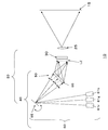
- FIG. 2 is a diagram for explaining the operating principle of the illumination device 40 of FIG. In FIG. 2, only some components in the lighting device 40 are illustrated for the sake of simplicity of explanation.
- the illumination device 40 according to the present embodiment includes an optical element 50 that directs the traveling direction of coherent light toward the illuminated region LZ, and an irradiation device 60 that irradiates the optical element 50 with coherent light.
- the optical element 50 includes a hologram recording medium 55 that can reproduce an image of a scattering plate (not shown).
- the hologram recording medium 55 can receive the coherent light emitted from the irradiation device 60 as the reproduction illumination light La and diffract the coherent light with high efficiency.
- the hologram recording medium 55 can reproduce the image of the scattering plate by diffracting coherent light incident on each position, in other words, each minute region that should be called each point. .
- the irradiation device 60 is configured so that the coherent light irradiated onto the hologram recording medium 55 scans on the hologram recording medium 55 by the optical element 50. Therefore, the region on the hologram recording medium 55 irradiated with the coherent light by the irradiation device 60 at a certain moment is a part of the surface of the hologram recording medium 55, and in particular in the illustrated example, a minute region to be called a point. It has become.
- the coherent light emitted from the irradiation device 60 and scanned on the hologram recording medium 55 is diffracted by the hologram recording medium 55 at each position (each point or each region (hereinafter the same)) on the hologram recording medium 55. Incidence is made at an incident angle that satisfies the conditions.
- the coherent light incident on each position of the hologram recording medium 55 from the irradiation device 60 is diffracted by the hologram recording medium 55 and illuminates areas that overlap each other at least partially.
- the coherent light incident on each position of the hologram recording medium 55 from the irradiation device 60 is diffracted by the hologram recording medium 55 to illuminate the same illuminated region LZ. .
- the coherent light incident on each position of the hologram recording medium 55 from the irradiation device 60 is superimposed on the illuminated area LZ to reproduce the image of the scattering plate. Yes. That is, the coherent light that has entered the hologram recording medium 55 from the irradiation device 60 is diffused (expanded) by the optical element 50 and enters the illuminated area LZ.
- FIG. 3 is a diagram for explaining how the image of the scattering plate 6 is formed as interference fringes on the hologram recording medium 55.
- the scattering plate 6 is a reference member that scatters light, and a specific form of the reference member is not limited.
- the hologram recording medium 55 is manufactured using the scattered light from the actual scattering plate 6 as the object light Lo.
- FIG. 3 shows a state where the photosensitive light 58 having photosensitivity that forms the hologram recording medium 55 is exposed to the reference light Lr and the object light Lo, which are coherent light beams having coherence with each other. Has been.
- the reference light Lr for example, laser light from a laser light source that oscillates laser light in a specific wavelength region is used.
- the reference light Lr passes through the condensing element 7 made of a lens and enters the hologram photosensitive material 58.
- the laser light that forms the reference light Lr is incident on the condensing element 7 as a parallel light beam parallel to the optical axis of the condensing element 7.
- the reference light Lr passes through the condensing element 7, so that it is shaped (converted) into a convergent light beam from the parallel light beam so far, and is incident on the hologram photosensitive material 58.
- the focal position FP of the convergent light beam Lr is at a position past the hologram photosensitive material 58.
- the hologram photosensitive material 58 is disposed between the condensing element 7 and the focal position FP of the convergent light beam Lr collected by the condensing element 7.
- the object light Lo is incident on the hologram photosensitive material 58 as scattered light from the scattering plate 6 made of, for example, opal glass.
- the hologram recording medium 55 to be manufactured is a transmission type, and the object light Lo enters the hologram photosensitive material 58 from the same side as the reference light Lr.
- the object light Lo is premised on having coherency with the reference light Lr. Therefore, for example, laser light oscillated from the same laser light source can be dispersed, and one of the dispersed light can be used as the reference light Lr and the other can be used as the object light Lo.
- a parallel light beam parallel to the normal direction to the plate surface of the scattering plate 6 is incident on and scattered by the scattering plate 6, and the scattered light transmitted through the scattering plate 6 is the object light Lo.
- the light enters the hologram photosensitive material 58.
- the object light Lo from the scattering plate 6 is incident on the hologram photosensitive material 58 with a substantially uniform light amount distribution. Is possible.
- the reference light Lr is incident on each position of the hologram photosensitive material 58 with a substantially uniform light amount from the entire area of the exit surface 6 a of the scattering plate 6. It becomes easy. In such a case, the light incident on each position of the obtained hologram recording medium 55 reproduces the image 5 of the scattering plate 6 with the same brightness, and the reproduced scattering plate 6 It can be realized that the image 5 is observed with substantially uniform brightness.
- the hologram recording material 58 when the hologram recording material 58 is exposed to the reference light Lr and the object light Lo, an interference fringe formed by the interference of the reference light Lr and the object light Lo is generated. It is recorded on the hologram recording material 58 as a pattern (in the case of a volume hologram, for example, a refractive index modulation pattern). Thereafter, appropriate post-processing corresponding to the type of the hologram recording material 58 is performed, and the hologram recording material 55 is obtained.
- a pattern in the case of a volume hologram, for example, a refractive index modulation pattern
- FIG. 4 is a diagram for explaining a state in which the image of the scattering plate is reproduced using the interference fringes formed on the hologram recording medium 55 obtained through the exposure process of FIG.
- the hologram recording medium 55 formed of the hologram photosensitive material 58 of FIG. 3 is light having the same wavelength as the laser light used in the exposure process, and the optical path of the reference light Lr in the exposure process The light traveling in the opposite direction satisfies the Bragg condition. That is, as shown in FIG. 4, the reference point SP positioned with respect to the hologram recording medium 55 in the same positional relationship as the relative position of the focal point FP (see FIG. 3) with respect to the hologram photosensitive material 58 during the exposure process.
- the divergent light beam that diverges from the light beam and has the same wavelength as the reference light Lr during the exposure process is diffracted by the hologram recording medium 55 as the reproduction illumination light La, and is relative to the hologram photosensitive material 58 during the exposure process.
- a reproduced image 5 of the scattering plate 6 is generated at a specific position with respect to the hologram recording medium 50 that has the same positional relationship as the position (see FIG. 3).
- the reproduction light (light obtained by diffracting the reproduction illumination light La by the hologram recording medium 55) Lb that generates the reproduction image 5 of the scattering plate 6 travels from the scattering plate 6 toward the hologram photosensitive material 58 during the exposure process.
- Each point of the image 5 of the scattering plate 6 is reproduced as light traveling in the opposite direction along the optical path of the object light Lo that has been emitted.
- the scattered light Lo emitted from each position on the exit surface 6 a of the scattering plate 6 in the exposure process is incident on almost the entire region of the hologram photosensitive material 58. Is spreading (spreading).
- the object light Lo from the entire area of the exit surface 6 a of the scattering plate 6 is incident on each position on the hologram photosensitive material 58, and as a result, information on the entire exit surface 6 a is placed on each position of the hologram recording medium 55. Each is recorded. For this reason, each light which forms the divergent light beam from the reference point SP functioning as the reproduction illumination light La shown in FIG. 4 is incident on each position of the hologram recording medium 55 independently and has the same contour.
- the image 5 of the scattering plate 6 can be reproduced at the same position (illuminated area LZ).
- the irradiation device 60 changes the traveling direction of the coherent light from the three color laser light sources 61 r, 61 g, and 61 b that generate coherent light, respectively.
- a scanning device 65 a scanning device 65.
- the laser light sources 61r, 61g, and 61b emit coherent light with different wavelength bands. Specifically, the laser light source 61r emits red light, the laser light source 61g emits green light, and the laser light source 61b Emits blue light. In addition to these three types of laser light sources, a laser light source having a separate wavelength band, that is, emitting light in another color (for example, yellow) may be provided. Further, at least one of the laser light sources 61r, 61g, and 61b may be replaced with a laser light source that emits light of a different color.
- the hologram recording medium 55 is provided with three recording areas 55r, 55g, and 55b corresponding to the laser light sources 61r, 61g, and 61b as shown in an enlarged view in FIG.
- Red coherent light from the laser light source 61r reflected by the scanning device 65 is incident on the recording area 55r, thereby generating an image 5 of the scattering plate 6 made of red reproduction light over the entire illuminated area LZ.
- the scanning device 65 changes the reflection angle of the red coherent light from the laser light source 61r with time, and accordingly, the irradiation position of the red coherent light in the recording area 55r also changes, but deviates from the recording area 55r.
- the reflection angle of the scanning device 65 is controlled so that the red coherent light from the scanning device 65 is not incident on the position.
- green coherent light from the laser light source 61g reflected by the scanning device 65 is incident on the recording area 55g, and an image 5 of the scattering plate 6 made of green reproduction light is generated over the entire illuminated area LZ.
- blue coherent light from the laser light source 61b reflected by the scanning device 65 is incident on the recording area 55b, and an image 5 of the scattering plate 6 made of blue reproduction light is generated over the entire illuminated area LZ. .
- the illuminated area LZ is illuminated with three colors of red, green and blue.
- the laser light sources 61r, 61g, and 61b simultaneously emit coherent light, these three colors are mixed and illuminated in white in the illuminated region LZ.
- the recording areas 55r, 55g, and 55b are not necessarily arranged in close contact with each other, and there may be a gap between them. In this case, the coherent light reflected by the scanning device 65 is not incident on the gap, but there is no practical problem. Further, the recording areas 55r, 55g, and 55b do not need to have the same area. However, if interference fringes are formed overlapping these recording areas 55r, 55g, and 55b, the refractive index modulation amount per interference fringe corresponding to each color is reduced, and as a result, compared to the case where there is a single-color interference fringe. Thus, the brightness of the illuminated area LZ is different. For this reason, it is desirable that the recording areas 55r, 55g, and 55b do not overlap.
- the reference light Lr and the object light Lo are irradiated for each recording area, and interference fringes are formed in the corresponding recording areas according to the principle of FIG. That's fine.
- the type of laser light source provided in the irradiation device 60 is not particularly limited.
- the hologram recording medium 55 may be divided into four regions in association with the laser light sources.
- the scanning device 65 changes the traveling direction of the coherent light with time, and directs it in various directions so that the traveling direction of the coherent light is not constant. As a result, the coherent light whose traveling direction is changed by the scanning device 65 scans the incident surface of the hologram recording medium 55 of the optical element 50. In the example of FIG. 1, since three types of coherent light from the laser light sources 61r, 61g, and 61b are incident on the scanning device 65, the scanning device 65 changes the reflection angle of these coherent light over time to generate a hologram. The respective incident surfaces of the recording areas 55r, 55g, and 55b of the recording medium 55 are scanned.
- the scanning device 65 includes a reflecting device 66 having a reflecting surface 66a that can be rotated about one axis RA1.
- FIG. 6 is a diagram for explaining the scanning path of the scanning device 65.
- the reflection device 66 includes a mirror device having a mirror as a reflection surface 66a that can be rotated about one axis RA1.
- the mirror device 66 changes the traveling direction of coherent light from the laser light sources 61r, 61g, and 61b by changing the orientation of the mirror 66a.
- the mirror device 66 generally receives coherent light from the laser light sources 61r, 61g, 61b at the reference point SP.
- the coherent light whose traveling direction has been finally adjusted by the mirror device 66 enters the hologram recording medium 55 of the optical element 50 as reproduction illumination light La (see FIG. 4) that can form one light beam diverging from the reference point SP. obtain.
- the coherent light from the irradiation device 60 scans on the hologram recording medium 55, and the image of the scattering plate 6 in which the coherent light incident on each position on the hologram recording medium 55 has the same contour. 5 is reproduced at the same position (illuminated area LZ).
- the mirror device 66 shown in FIG. 2 is configured to rotate the mirror 66a along one axis RA1.
- the rotation axis RA ⁇ b> 1 of the mirror 66 a has an XY coordinate system defined on the plate surface of the hologram recording medium 55 (that is, the XY plane is parallel to the plate surface of the hologram recording medium 55. It extends parallel to the Y axis of the (XY coordinate system). Then, since the mirror 66a rotates around the axis line RA1 parallel to the Y axis of the XY coordinate system defined on the plate surface of the hologram recording medium 55, the coherent light from the irradiation device 60 is applied to the optical element 50.
- the incident point IP reciprocates in a direction parallel to the X axis of the XY coordinate system defined on the plate surface of the hologram recording medium 55. That is, in the example shown in FIG. 7, the irradiation device 60 irradiates the optical element 50 with coherent light so that the coherent light scans on the hologram recording medium 55 along a linear path.
- the scanning device 65 configured by the mirror device 66 or the like is a member that can rotate at least around the axis A1, and is configured by using, for example, MEMS.
- the scanning device 65 periodically rotates, but the rotation frequency is not particularly limited.
- the hologram recording material 58 may shrink when the hologram recording medium 55 is produced.
- the traveling direction of the light incident on the hologram recording medium 55 of the optical element 50 does not take exactly the same path as the one light beam included in the divergent light beam from the reference point SP, it is illuminated.
- the image 5 can be reproduced in the region LZ.
- the mirror (reflection surface) 66a of the mirror device 66 constituting the scanning device 65 is inevitably deviated from the rotation axis RA1. Therefore, when the mirror 66a is rotated around the rotation axis RA1 that does not pass through the reference point SP, the light incident on the hologram recording medium 55 may not be a single light beam that forms a divergent light beam from the reference point SP. is there.
- the image 5 can be substantially reproduced by being superimposed on the illuminated region LZ by coherent light from the irradiation device 60 having the illustrated configuration.
- the irradiation device 60 irradiates the optical element 50 with the coherent light so that the coherent light scans the hologram recording medium 55 of the optical element 50.
- the laser light sources 61r, 61g, and 61b generate coherent light having a specific wavelength that travels along a certain direction, and the coherent light is irradiated to the same reference point of the scanning device 65 to change the traveling direction. It is done. More specifically, each coherent light travels toward the hologram recording medium 55 at a reflection angle corresponding to the incident angle from the laser light sources 61r, 61g, 61b.
- the scanning device 65 causes coherent light of a corresponding specific wavelength to enter a specific position in each recording area on the hologram recording medium 55 at an incident angle that satisfies the Bragg condition at the position.
- the coherent light incident on a specific position in each recording area is superimposed on the entire illuminated area LZ and reproduced by the diffraction due to the interference fringes recorded on the hologram recording medium 55, respectively.
- the coherent light that has entered the specific position in each recording area of the hologram recording medium 55 from the irradiation device 60 is diffused (expanded) by the optical element 50 and enters the entire illuminated area LZ. become.
- the irradiation device 60 illuminates the illuminated area LZ with coherent light.
- the laser light sources 61r, 61g, and 61b emit light in different colors, and the image 5 of the scattering plate 6 is reproduced in each color in the illuminated region LZ. Therefore, when the laser light sources 61r, 61g, and 61b emit light at the same time, the illuminated area LZ is illuminated with white in which three colors are mixed.
- the incident position of the coherent light from the scanning device 65 on the hologram recording medium 55 moves with time in each recording area by driving the scanning device 65.
- the spatial light modulator 30 is arranged at a position overlapping the illuminated area LZ of the illumination device 40. For this reason, the spatial light modulator 30 is illuminated in a planar shape by the illumination device 40, and forms an image by selecting and transmitting the coherent light for each pixel.
- This image is projected onto the screen 15 by the projection optical system 25.
- the coherent light projected on the screen 15 is diffused and recognized as an image by the observer. However, at this time, the coherent light projected on the screen interferes by diffusion and causes speckle.
- the mode refers to speckle patterns that are uncorrelated with each other.
- speckle patterns that are uncorrelated with each other.
- the mode is the same as the number of times the incident direction of the coherent light has changed during the time that cannot be resolved by the human eye. Will exist.
- the interference patterns of light are uncorrelated and averaged, and as a result, speckles observed by the observer's eyes are considered inconspicuous.
- the coherent light is irradiated onto the optical element 50 so as to scan the hologram recording medium 55.
- the coherent light incident on each position of the hologram recording medium 55 from the irradiation device 60 illuminates the entire illuminated area LZ with the coherent light, but the illumination of the coherent light that illuminates the illuminated area LZ.
- the directions are different from each other. Since the position on the hologram recording medium 55 where the coherent light enters changes with time, the incident direction of the coherent light to the illuminated region LZ also changes with time.
- the coherent light continuously scans on the hologram recording medium 55.
- the incident direction of coherent light from the irradiation device 60 to the illuminated region LZ also changes continuously
- the incident direction of coherent light from the projection device 20 to the screen 15 also changes continuously.
- the speckle pattern generated on the screen 15 also changes greatly, and an uncorrelated speckle pattern. Will be superimposed.
- the frequency of scanning devices 65 such as MEMS mirrors and polygon mirrors that are commercially available is usually several hundred Hz or higher, and scanning devices 65 that reach tens of thousands of Hz are not uncommon.
- the incident direction of the coherent light changes temporally at each position on the screen 15 displaying an image, and this change is caused by human eyes.
- a non-correlated coherent light scattering pattern is multiplexed and observed by the human eye. Therefore, speckles generated corresponding to each scattering pattern are overlapped and averaged and observed by an observer. Thereby, speckles can be made very inconspicuous for an observer who observes the image displayed on the screen 15.
- speckles observed by humans include not only speckles on the screen caused by scattering of coherent light on the screen 15, but also scattering of coherent light before being projected on the screen. Speckle on the projection device side can also occur.
- the speckle pattern generated on the projection device side is projected onto the screen 15 via the spatial light modulator 30 so that it can be recognized by the observer.
- the coherent light continuously scans on the hologram recording medium 55, and the coherent light incident on each position of the hologram recording medium 55 is superimposed on the spatial light modulator 30, respectively. The entire illuminated area LZ is illuminated.
- the hologram recording medium 55 forms a new wavefront that is separate from the wavefront used to form the speckle pattern, and the illumination area LZ and further the spatial light modulator 30 are formed in a complex and uniform manner. Through this, the screen 15 is illuminated. Due to the formation of a new wavefront on the hologram recording medium 55, the speckle pattern generated on the projection apparatus side is made invisible.
- speckle contrast unit%
- This speckle contrast is defined as a value obtained by dividing the standard deviation of the actual luminance variation on the screen divided by the average luminance value when displaying a test pattern image that should have a uniform luminance distribution. Amount. The larger the speckle contrast value is, the larger the speckle occurrence level on the screen is, which indicates that the spot-like luminance unevenness pattern is more prominently presented to the observer.
- the speckle contrast of a basic projection type image display device configured using one laser light source and a reflective volume hologram was measured and found to be 3.0% ( Condition 1). Further, as the above-described optical element 50, an uneven shape designed by using a computer so that the image 5 of the scattering plate 6 can be reproduced when receiving specific reproduction illumination light instead of the reflective volume hologram.
- the speckle contrast in the case of using the relief type hologram as a computer-generated hologram (CGH) having a ratio of 3.7% was (Condition 2).
- a speckle contrast of 6.0% or less is a standard (for example, WO / 2001/081996) as a level at which an uneven brightness pattern is hardly recognized when an observer observes with the naked eye.
- the basic form described above sufficiently satisfies this standard.
- brightness unevenness (brightness unevenness) that could be visually recognized did not occur.
- the laser light from the laser light source is shaped into a parallel light beam and incident on the spatial light modulator 30, that is, the spatial light modulator 30 of the projection display apparatus 10 shown in FIG.
- the speckle contrast was 20.7% (Condition 3). Under these conditions, a spot-like luminance unevenness pattern was observed quite noticeably by visual observation.
- the laser light source is replaced with a green LED (non-coherent light source) and light from this LED light source is incident on the spatial light modulator 30, that is, the projection type video display device 10 shown in FIG.
- the speckle contrast was 4.0% (Condition 4). Under these conditions, brightness unevenness (brightness unevenness) that could be visually recognized by naked eye observation did not occur.
- condition 1 and condition 2 were much better than the results of condition 3, and even better compared to the measurement results of condition 4.
- the problem of speckle generation is a problem inherent in the case of using a coherent light source such as a laser beam in practice, and it is necessary to consider in an apparatus using a non-coherent light source such as an LED. There is no problem.
- condition 1 and condition 2 as compared with condition 4, an optical element 50 that can cause speckles is added. From these points, it can be said that Condition 1 and Condition 2 were sufficient to cope with speckle defects.
- the optical element 50 for making speckles inconspicuous can also function as an optical member for shaping and adjusting the beam form of coherent light emitted from the irradiation device 60. Therefore, the optical system can be reduced in size and simplified.
- coherent light incident on a specific position in each recording area of the hologram recording medium 55 generates the image 5 of the scattering plate 6 in each color over the entire illuminated area LZ.
- a spatial light modulator 30 is arranged so as to overlap the image 5. Therefore, all of the light diffracted by the hologram recording medium 55 can be used for image formation, and the use efficiency of the light from the laser light sources 61r, 61g, 61b is excellent.
- the coherent light emitted from the laser light sources 61r, 61g, and 61b is incident on the scanning device 65 as parallel light, and the coherent light reflected by the scanning device 65 is incident on the hologram recording medium 55 as divergent light.
- the projection type video display apparatus 10a shows an example of the projection type video display apparatus 10a.
- coherent light from the laser light sources 61 r, 61 g, 61 b is incident on three places of the scanning device 65, and the coherent light is reflected toward the hologram recording medium 55 from each place. become.
- the scanning device 65 since the scanning device 65 periodically rotates, the reflection angle of the reflected coherent light changes accordingly, but the three types of reflected coherent light remain in a parallel state. Accordingly, the corresponding reflected coherent light is incident on the three recording areas 55r, 55g, and 55b in the hologram recording medium 55, respectively.
- the reflected light of the light beam incident in parallel to the scanning device 65 is guided to the hologram recording medium 55.
- the reference light Lr to be generated it is necessary to divide the hologram recording medium 55 into three regions in place of the convergent light beam shown in FIG.
- the coherent light irradiated on the mirror surface of the scanning device 65 is dispersed and no strong light is irradiated on a specific portion of the mirror surface, so that the durability of the scanning device 65 can be improved.
- the apparatus of FIG. 7 is superior to the apparatus of FIG. 1 in terms of adjustment effort and the like.
- the area of the mirror surface must be increased compared to the case where three types of coherent light converge on one point of the mirror surface, and the power consumption increases due to the increase in the size of the scanning device 65. There is a risk.
- FIG. 8 is a diagram showing an example of a projection display apparatus 10b using a laser array 62 in which three color laser light sources 61r, 61g, 61b are built in one chip as a light source. Since the laser light sources 61r, 61g, 61b in the laser array 62 emit coherent light in parallel directions, a condensing lens 63 is provided as a converging optical system, and these coherent light is converged at the same point of the scanning device 65. ing. Therefore, the apparatus of FIG. 8 uses the same hologram recording medium as the apparatus of FIG. 1, and the configuration of the projection optical system is the same as that of FIG.
- the use of the laser array 62 facilitates the positioning of the laser light sources 61r, 61g, 61b, and also suppresses variations in the optical path between the devices.
- FIG. 9 is a diagram illustrating an example of a projection display apparatus 10 c in which parallel coherent light from the laser array 62 is directly incident on the scanning device 65 and reflected light from the scanning device 65 is incident on the hologram recording medium 55. .
- the optical path of coherent light in FIG. 9 is the same as in FIG. 7, and has the same advantages and disadvantages as in FIG. As much as the laser array 62 is used, the laser light sources 61r, 61g, and 61b can be positioned more easily than in FIG.
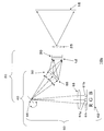
- FIG. 10 is a diagram illustrating an example of a projection display apparatus 10d configured using a two-dimensional laser array 62 in which laser arrays 62r, 62g, and 62b in which monochromatic laser light sources are arranged horizontally are arranged in the vertical direction. is there.
- the coherent light emitted from these laser light sources passes through a condenser lens 67 as a converging optical system and is converged at the same point of the scanning device 65.
- the scanning device 65 reflects the light at an angle corresponding to the incident angle of the coherent light, and enters each of nine recording regions provided on the hologram recording medium 55. Each of the coherent lights from the nine laser light sources is scanned in the corresponding recording area by the scanning device 65.
- the arrangement of the colors of the laser array 62 and the arrangement of the colors of the recording areas of the hologram recording medium are symmetrical in the diagonal direction.
- the number of laser light sources to be used is three times that of the apparatus of FIG. 1 and the like, so that the illuminated area LZ can be illuminated more brightly, and the output of the illumination intensity can be increased. It can be easily realized.
- the reflection characteristics of the screen intensity distribution of reflected light depending on the incident angle
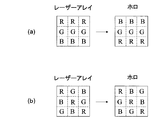
- light of each color of RGB is incident from various directions, so that it becomes difficult for the observer to visually recognize the color unevenness. Therefore, if the color arrangement of the laser light source of the laser array 62 is adjusted or randomized in advance according to the reflection characteristics of the screen, color unevenness of the display color of the screen can be suppressed.
- FIG. 11A shows an example of a general arrangement in which the colors of the laser light sources of the laser array 62 are red, green, and blue in the vertical direction
- FIG. 11B shows the color characteristics of the screen.
- an example in which the color arrangement of the laser light sources of the laser array 62 is entirely random is shown.
- the color arrangement of the recording area of the hologram recording medium is symmetrical in the diagonal direction, in the case of FIG. 10B, the color arrangement of the recording area is also random, and the display color unevenness is suppressed. it can.
- a part of the coherent light from the irradiation device 60 passes through the hologram recording medium 55 without being diffracted by the hologram recording medium 55.
- Such light is called zero order light. If zero-order light enters the illuminated area LZ, an abnormal area (a dotted area, a linear area, or a planar area) in which the brightness (luminance) increases sharply compared with the surrounding area is the illuminated area LZ. Will occur within.
- the spatial light modulator 30 and the projection optical system 25 are not arranged in the direction in which the zero-order light travels, and therefore the zero-order light can be avoided relatively easily.
- the transmission type hologram recording medium 55 shown in FIG. 2 or the like there is a high possibility that the spatial light modulator 30 and the projection optical system 25 are arranged in a direction close to the direction in which the zero-order light travels. is necessary.
- the spatial light modulator 30 and the projection optical system 25 are not arranged in that direction.
- the optical path of the coherent light reflected by the scanning device 65 changes, so that zero-order light can pass through the spatial light modulator 30 and the projection optical system 25. There is sex. For this reason, even when the configuration of FIG.
- the scanning device 65 according to the traveling path of the 0th-order light so that the 0th-order light does not pass through the spatial light modulator 30 and the projection optical system 25, It is necessary to design the arrangement location of the spatial light modulator 30 and the projection optical system 25.
- the laser light sources 61r, 61g, and 61b shown in FIG. 1 and the like may emit coherent light at the same time, or may emit coherent light in order.
- the illuminated area LZ is illuminated with white, with each color mixed.
- a full color display can be realized by providing a color filter on the micro display as the spatial light modulator 30 installed in the illuminated area LZ and allowing only a specific color to pass through each pixel.
- the illumination color of the illuminated area LZ changes in order from, for example, red ⁇ green ⁇ blue.
- Full color display can be realized.
- one frame of red pixels is drawn on the micro display while the illumination color of the illuminated region LZ is red, and then one frame while the illumination color of the illuminated region LZ is green.
- the green pixels are drawn for one minute, and finally, the blue pixels for one frame are drawn while the illumination color of the illuminated area LZ is blue.
- This series of drawing processing is performed, for example, several tens of times per second.
- the three color laser light sources 61r, 61g, and 61b emit coherent light in order, it is not necessary to provide a color filter on the micro display, so that the brightness of the micro display can be further increased and a clearer image can be displayed on the screen. 15 can be displayed. In addition, it is possible to reduce the light intensity of the laser light sources 61r, 61g, 61b, considering in advance that there is no light absorption by the color filter, thereby improving durability and improving power consumption.
- the configuration of a control circuit that performs light emission control of the laser light source and display control of the micro display can be simplified.
- the hologram recording medium 55 described with reference to FIG. 1 and the like has three recording areas 55r, 55g, and 55b corresponding to the colors of the laser light sources 61r, 61g, and 61b. In each of these three recording areas, as shown in FIG. 12, interference fringes corresponding to the respective colors are multiplexed and recorded in the plane direction.
- the hologram recording medium is designed so that the diffraction conditions of the coherent light of other colors (wavelength regions) do not interfere with each other at the designed incident angle of the coherent light of each color, that is, the wavelength spectra of the mutual diffraction do not interfere with each other. It is necessary to adjust the film thickness 55 and the refractive index modulation amount ⁇ n.
- FIG. 12 shows multiple recording of the reflection type hologram recording medium 55, but a transmission type hologram recording medium 55 may be used as shown in FIG.
- the hologram recording medium 55 may have a laminated structure, and a specific color may be diffracted by each layer.
- a red layer 55r, a green layer 55g, and a blue layer 55b are stacked from top to bottom, and each layer (coherent light of each wavelength) is stacked on each layer. Interference fringes for causing interference are recorded.
- each of the layers 55r, 55g, and 55b is divided into three recording areas in the plane direction of the hologram recording medium 55, and is used to actually reproduce the scattering plate image.
- the recording area to be recorded is only the hatched area. Therefore, when forming interference fringes for each layer, the interference fringes need only be formed in the hatched region.
- interference fringes may be formed in all areas of each layer, and the entire area in the plane direction may be used for reproducing the scattering plate image.
- a reflection type hologram recording medium (hereinafter referred to as reflection type holo) has higher wavelength selectivity than a transmission type hologram recording medium (hereinafter referred to as transmission type holo). That is, the reflection type holo can diffract coherent light having a desired wavelength only by a desired layer even if interference fringes corresponding to different wavelengths are laminated.
- the reflection type holo is also excellent in that it is easy to remove the influence of zero-order light.
- the transmission type holo has a wide diffractable spectrum and a wide tolerance of the laser light source. Will be. Therefore, in general, it is difficult to make the transmission type holo a laminated structure.
- the lighting device 40 can be usefully used in various aspects.
- the illumination device 40 can be used as simple illumination, and in this case, unevenness in brightness (luminance unevenness, flicker) can be made inconspicuous.
- the configuration of FIG. 1 includes laser light sources 61r, 61g, and 61b that emit light in three colors
- the white light illumination device 40 can be realized by simultaneously emitting these laser light sources.
- the illumination device 40 capable of switching illumination colors at various timings can be realized by sequentially or arbitrarily selecting the laser light sources 61r, 61g, and 61b to emit light.
- the laser light sources 61r, 61g, and 61b emit light at the same time, white light is obtained. Therefore, this white light may be used as illumination for a scanner (for example, an image reading device).
- the speckle generated on the target object can be made inconspicuous by arranging the target object to be scanned on the illuminated region LZ of the lighting device 40. As a result, it is possible to eliminate image correction means and the like that are conventionally required.
- the illuminated area LZ by the illuminating device 40 may be a surface in the same manner as described above.
- the illuminated region LZ by the illumination device 40 may be an elongated region (region also called a linear shape) extending in one direction.
- two-dimensional image information can be read by the illuminating device 40 incorporated in the scanner moving relative to the object along a direction orthogonal to the one direction.
- the optical element 50 may include a plurality of hologram recording media 55-1, 55-2,... Arranged side by side so as not to overlap.
- Each of the hologram recording media 55-1, 55-2,... Shown in FIG. 14 is formed in a strip shape, and is arranged side by side in the direction orthogonal to the longitudinal direction without any gap.
- the hologram recording media 55-1, 55-2,... Are located on the same virtual plane.
- Each hologram recording medium 55-1, 55-2,... Has an image 5 of the scattering plate 6 on the illuminated areas LZ-1, LZ-2,. Generate, in other words, illuminate the illuminated areas LZ-1, LZ-2,... With coherent light.
- Each of the illuminated areas LZ-1, LZ-2,... Is formed as an elongated area extending in one direction (an area that is also called a linear shape), and arranged side by side in the direction perpendicular to the longitudinal direction without any gap. Further, the illuminated areas LZ-1, LZ-2,... Are located on the same virtual plane.
- the illuminated areas LZ-1, LZ-2,... May be illuminated as follows.
- the irradiation device 60 repeatedly scans the path along the longitudinal direction (the one direction) of the first hologram recording medium 55-1, so that the coherent light repeatedly scans the first hologram recording medium 55- of the optical element 50. 1 is irradiated with the coherent light.
- the coherent light incident on each position of the first hologram recording medium 55-1 is superimposed on the first illumination area LZ-1 to reproduce the image 5 of the linear or elongated scattering plate 6, and the first One illumination region LZ-1 is illuminated with coherent light.
- the irradiation device 60 irradiates the second hologram recording medium 55-2 adjacent to the first hologram recording medium 55-1 with the coherent light, and the first illuminated region LZ-1 Instead, the second illuminated area LZ-2 adjacent to the first illuminated area LZ-1 is illuminated with coherent light.
- the hologram recording medium is sequentially irradiated with coherent light, and the illuminated area corresponding to the hologram recording medium is illuminated with the coherent light. According to such a method, it is possible to read two-dimensional image information without moving the illumination device.
- speckle can be effectively made inconspicuous.
- this effect is mainly due to the lighting device 40.
- this lighting device 40 is combined with various known spatial light modulators, projection optical systems, screens, etc., speckles can be effectively made inconspicuous.
- the spatial light modulator, the projection optical system, and the screen are not limited to those illustrated, and various known members, components, devices, and the like can be used.
- the hologram recording medium 55 is manufactured by the interference exposure method using the planar scattering plate 6 having a shape corresponding to the incident surface of the spatial light modulator 30 .
- the hologram recording medium 55 may be manufactured by an interference exposure method using a scattering plate having a certain pattern. In this case, the image of the scattering plate having a certain pattern is reproduced by the hologram recording medium 55. In other words, the optical element 50 (hologram recording medium 55) illuminates the illuminated area LZ having a certain pattern.
- the spatial light modulator 30 and the projection optical system 25 are also omitted from the basic form described above, and the screen 15 is disposed on the screen 15 by overlapping with the illuminated region LZ. Any pattern recorded on the hologram recording medium 55 can be displayed. Also in this display device, the speckles on the screen 15 can be made inconspicuous by the irradiation device 60 irradiating the optical element 50 with the coherent light so that the coherent light scans the hologram recording medium 55. .
- FIG. 15 discloses an example of such an example.
- the optical element 50 includes first to third hologram recording media 55-1, 55-2, and 55-3.
- the first to third hologram recording media 55-1, 55-2, and 55-3 are arranged on surfaces parallel to the incident surface of the optical element 50 so as not to overlap each other.
- Each of the hologram recording media 55-1, 55-2, 55-3 can reproduce the image 5 having the outline of the arrow, in other words, the illuminated areas LZ-1, LZ- having the outline of the arrow. 2 and LZ-3 can be illuminated with coherent light.
- the first to third illuminated areas LZ-1, LZ-2, and LZ-3 corresponding to the hologram recording media 55-1, 55-2, and 55-3 overlap each other on the same virtual plane.
- the directions indicated by the arrows forming the illuminated areas LZ-1, LZ-2, and LZ-3 are all the same, and the first to third illuminated areas LZ-1, LZ-2 and LZ-3 are positioned in order.
- the coherent light from the irradiation device 60 is scanning the first hologram recording medium 55-1, the first illuminated area LZ-1 located at the rearmost position is illuminated.
- the coherent light from the irradiation device 60 scans on the second hologram recording medium 55-2, and the second illuminated region LZ-2 located in the middle is formed. Illuminated. Thereafter, when the coherent light from the irradiation device 60 scans the third hologram recording medium 55-3, the foremost third illuminated region LZ-3 is illuminated.
- the scanning device 65 is an example of the uniaxial rotation type mirror device 66 that changes the traveling direction of the coherent light by reflection, the scanning device 65 is not limited thereto.
- the scanning device 65 has a second rotation in which the mirror (reflection surface 66a) of the mirror device 66 intersects not only the first rotation axis RA1 but also the first rotation axis RA1. It may be rotatable about the axis RA2. In the example shown in FIG.
- the second rotation axis RA2 of the mirror 66a is a first rotation axis RA1 extending in parallel with the Y axis of the XY coordinate system defined on the plate surface of the hologram recording medium 55.
- the incident point IP of the coherent light from the irradiation device 60 to the optical element 50 is the plate of the hologram recording medium 55. It is possible to move in a two-dimensional direction on the surface. For this reason, as shown in FIG. 16 as an example, the incident point IP of the coherent light to the optical element 50 can be moved on the circumference.
- the scanning device 65 may include two or more mirror devices 66.
- the mirror 66a of the mirror device 66 can be rotated only about a single axis, the incident point IP of the coherent light from the irradiation device 60 to the optical element 50 is expressed by the hologram recording medium 55. It can be moved in a two-dimensional direction on the plate surface.
- mirror device 66a included in the scanning device 65 includes a MEMS mirror, a polygon mirror, and the like.
- the scanning device 65 may include a device other than the reflection device (for example, the mirror device 66 described above) that changes the traveling direction of the coherent light by reflection.
- the scanning device 65 may include a refractive prism, a lens, and the like.
- the scanning device 65 is not essential, and the light sources 61r, 61g, and 61b of the irradiation device 60 are configured to be displaceable (movable, swinging, and rotating) with respect to the optical element 50, and the light sources 61r, 61g, and 61b are optical.
- the hologram recording medium 55 may be scanned with coherent light emitted from the light sources 61r, 61g, and 61b by displacement with respect to the element.
- the light source 61r, 61g, 61b of the irradiation device 60 has been described on the assumption that the laser light shaped as a linear light beam is oscillated, the present invention is not limited thereto.
- the coherent light irradiated to each position of the optical element 50 is shaped by the optical element 50 into a light beam that enters the entire illuminated area LZ. Therefore, there is no inconvenience even if the coherent light irradiated to the optical element 50 from the light sources 61r, 61g, 61b of the irradiation device 60 is not accurately shaped. For this reason, the coherent light generated from the light sources 61r, 61g, and 61b may be diverging light.
- the cross-sectional shape of the coherent light generated from the light sources 61r, 61g, and 61b may be an ellipse or the like instead of a circle.
- the transverse mode of coherent light generated from the light sources 61r, 61g, 61b may be a multimode.
- the coherent light is incident not on a point but on a region having a certain area when entering the hologram recording medium 55 of the optical element 50.
- the light diffracted by the hologram recording medium 55 and incident on each position of the illuminated area LZ is multiplexed in angle.
- coherent light is incident on each position of the illuminated area LZ from a certain angle range. Speckle can be made more inconspicuous by such multiplexing of angles.
- the scanning device 65 may further include a condensing lens 67 disposed on the downstream side of the mirror device 66 along the optical path of the coherent light.
- the light from the mirror device 66 that travels along the optical path of the light beam constituting the divergent light beam becomes light that travels in a certain direction by the condenser lens 67.
- the irradiation device 60 causes the coherent light to be incident on the optical element 50 so as to follow the optical path of the light beam constituting the parallel light flux.
- a parallel light beam is used as the reference light Lr instead of the above-described convergent light beam in the exposure process when the hologram recording medium 55 is manufactured.
- Such a hologram recording medium 55 can be produced and duplicated more easily.
- the optical element 50 may include a plurality of hologram recording media 55. Further, the optical element 50 may include a volume hologram that is recorded using a photosensitive medium including a silver salt material. Further, the optical element 50 may include a transmission type volume hologram recording medium or a relief type (emboss type) hologram recording medium.
- a relief (embossed) hologram is recorded with hologram interference fringes due to the uneven structure on the surface.
- scattering due to the uneven structure on the surface may become a new speckle generation factor.
- the volume type hologram is preferable.
- the hologram interference fringe is recorded as a refractive index modulation pattern (refractive index distribution) inside the medium, it is not affected by scattering due to the uneven structure on the surface.
- the hologram recording medium 55 is preferably a volume hologram using a photopolymer.
- a so-called Fresnel type hologram recording medium is produced.
- a Fourier transform type hologram recording medium obtained by performing recording using a lens may be produced. Absent.
- a lens may also be used during image reproduction.
- the striped pattern (refractive index modulation pattern or concave / convex pattern) to be formed on the hologram recording medium 55 does not use the actual object light Lo and reference light Lr, but the planned wavelength and incident direction of the reproduction illumination light La. In addition, it may be designed using a computer based on the shape and position of the image to be reproduced.
- the hologram recording medium 55 obtained in this way is also called a computer-generated hologram.
- the hologram recording medium 55 as a computer-generated hologram corresponds to each coherent light in each wavelength range.
- the coherent light in each wavelength region may be diffracted in the corresponding region to reproduce an image.
- the optical element 50 includes the hologram recording medium 55 that expands the coherent light irradiated to each position and illuminates the entire illuminated area LZ using the expanded coherent light.
- the optical element 50 changes the traveling direction of the coherent light irradiated to each position and diffuses instead of the hologram recording medium 55 or in addition to the hologram recording medium 55 so that the entire area to be illuminated LZ is coherent light.
- the irradiating device 60 scans the lens array with the coherent light so as to irradiate the optical element 50 with the coherent light.
- the irradiation device 60 and the optical element 50 By configuring the irradiation device 60 and the optical element 50 so that the traveling direction of the coherent light incident on the position is changed by the lens array to illuminate the illuminated area LZ, speckles are effectively inconspicuous. Can be made.
- a lens array including at least three lenses corresponding to the laser light sources 61r, 61g, and 61b. Coherent light that is emitted from the corresponding laser light source and reflected by the scanning device 65 is incident on each lens. Each lens diffuses the incident coherent light and irradiates the entire illuminated area LZ. Thereby, even if the hologram recording medium 55 is not provided, the entire illuminated area LZ can be illuminated, for example, in white.
- the irradiation device 60 is configured to be able to scan the coherent light in the one-dimensional direction on the optical element 50, and the hologram recording medium 55 (or lens array) of the optical element 50 is irradiated to each position.
- the coherent light is configured to diffuse (spread and diverge) in a two-dimensional direction, whereby the illumination device 40 illuminates the two-dimensional illuminated area LZ.
- the present invention is not limited to such an example.
- the irradiation device 60 is configured to be able to scan the coherent light on the optical element 50 in a two-dimensional direction
- the hologram recording medium 55 (or lens array) of the optical element 50 is configured to diffuse (spread and diverge) the coherent light irradiated to each position in a two-dimensional direction.
- the illumination device 40 may illuminate the two-dimensional illuminated area LZ.
- the irradiation device 60 is configured to be able to scan the coherent light on the optical element 50 in a one-dimensional direction, and the hologram recording medium 55 (or lens array) of the optical element 50 is used. Is configured to diffuse (spread and diverge) the coherent light irradiated to each position in a one-dimensional direction, so that the illumination device 40 illuminates the one-dimensional illuminated region LZ. It may be.
- the scanning direction of the coherent light by the irradiation device 60 and the diffusion direction (expansion direction) of the hologram recording medium 55 (or lens array) of the optical element may be parallel to each other.
- the irradiation device 60 is configured to be able to scan the coherent light on the optical element 50 in a one-dimensional direction or a two-dimensional direction, and the hologram recording medium 55 (or lens array) of the optical element 50 is placed at each position.
- the irradiated coherent light may be configured to diffuse (spread and diverge) in a one-dimensional direction.
- the optical element 50 has a plurality of hologram recording media 55 (or lens arrays), and sequentially illuminates the illuminated area LZ corresponding to each hologram recording medium 55 (or lens array). By doing so, the illumination device 40 may illuminate a two-dimensional area.
- each illuminated area LZ may be sequentially illuminated at a speed as if it were illuminated simultaneously by the human eye, or it can be recognized that the illuminated area LZ is also illuminated sequentially by the human eye. It may be illuminated sequentially at such a slow speed.
Landscapes
- Physics & Mathematics (AREA)
- General Physics & Mathematics (AREA)
- Optics & Photonics (AREA)
- Engineering & Computer Science (AREA)
- Multimedia (AREA)
- Signal Processing (AREA)
- Projection Apparatus (AREA)
- Holo Graphy (AREA)
- Diffracting Gratings Or Hologram Optical Elements (AREA)
- Non-Portable Lighting Devices Or Systems Thereof (AREA)
- Liquid Crystal (AREA)
- Transforming Electric Information Into Light Information (AREA)
- Optical Elements Other Than Lenses (AREA)
- Mechanical Optical Scanning Systems (AREA)
Abstract
L'invention vise à rendre discrètes les granulations cohérentes et à minimiser efficacement l'inégalité de luminosité dans une zone éclairée en chevauchement par de la lumière diffractée par un support d'enregistrement holographique ou similaire. L'invention concerne : des éléments optiques (50) comprenant un support d'enregistrement holographique (55) qui peut reproduire une image d'un élément de référence ; et un appareil d'éclairage (60) qui produit de la lumière cohérente sur les éléments optiques (50) de sorte que ladite lumière cohérente balaie le support d'enregistrement holographique (55). L'appareil d'éclairage (60) comporte une source de lumière qui émet de la lumière cohérente et un dispositif de balayage (65) qui : peut régler un angle de réflexion auquel la lumière cohérente émise par la source de lumière est réfléchie ; et qui balaie le support d'enregistrement holographique (55) avec la lumière cohérente réfléchie. La source de lumière comporte une pluralité d'unités de source de lumière qui émettent une pluralité de faisceaux de lumière cohérente, dont chacun a une bande de longueurs d'ondes différente. Le support d'enregistrement holographique (55) comporte une pluralité de zones d'enregistrement qui sont balayées respectivement par la pluralité de faisceaux de lumière cohérente réfléchis par le dispositif de balayage (65). Chacune desdites zones d'enregistrement a un motif d'interférence qui diffracte la lumière cohérente de la bande de longueurs d'ondes correspondante. Les éléments optiques (50) font se chevaucher dans une zone éclairée la pluralité de faisceaux de lumière cohérente, diffractés par les motifs d'interférence dans la pluralité de zones d'enregistrement, reproduisant une image de l'élément de référence susmentionné.
Priority Applications (6)
| Application Number | Priority Date | Filing Date | Title |
|---|---|---|---|
| US13/821,103 US9377759B2 (en) | 2010-09-08 | 2011-09-08 | Illumination device, projection apparatus and projection-type image display apparatus |
| JP2012533027A JP5748130B2 (ja) | 2010-09-08 | 2011-09-08 | 照明装置、投射装置および投写型映像表示装置 |
| EP11823648.8A EP2615502B1 (fr) | 2010-09-08 | 2011-09-08 | Appareil d'éclairage, appareil de projection, et appareil d'affichage vidéo par projection |
| EP19205568.9A EP3623874B1 (fr) | 2010-09-08 | 2011-09-08 | Dispositif d'éclairage, appareil de projection et appareil d'affichage d'images de type projecteur |
| US15/162,971 US10146183B2 (en) | 2010-09-08 | 2016-05-24 | Illumination device, projection apparatus and projection-type image display apparatus |
| US16/169,005 US10948878B2 (en) | 2010-09-08 | 2018-10-24 | Illumination device, projection apparatus and projection-type image display apparatus |
Applications Claiming Priority (2)
| Application Number | Priority Date | Filing Date | Title |
|---|---|---|---|
| JP2010201384 | 2010-09-08 | ||
| JP2010-201384 | 2010-09-08 |
Related Child Applications (2)
| Application Number | Title | Priority Date | Filing Date |
|---|---|---|---|
| US13/821,103 A-371-Of-International US9377759B2 (en) | 2010-09-08 | 2011-09-08 | Illumination device, projection apparatus and projection-type image display apparatus |
| US15/162,971 Continuation US10146183B2 (en) | 2010-09-08 | 2016-05-24 | Illumination device, projection apparatus and projection-type image display apparatus |
Publications (1)
| Publication Number | Publication Date |
|---|---|
| WO2012033174A1 true WO2012033174A1 (fr) | 2012-03-15 |
Family
ID=45810770
Family Applications (1)
| Application Number | Title | Priority Date | Filing Date |
|---|---|---|---|
| PCT/JP2011/070519 WO2012033174A1 (fr) | 2010-09-08 | 2011-09-08 | Appareil d'éclairage, appareil de projection, et appareil d'affichage vidéo par projection |
Country Status (4)
| Country | Link |
|---|---|
| US (3) | US9377759B2 (fr) |
| EP (2) | EP2615502B1 (fr) |
| JP (4) | JP5748130B2 (fr) |
| WO (1) | WO2012033174A1 (fr) |
Cited By (19)
| Publication number | Priority date | Publication date | Assignee | Title |
|---|---|---|---|---|
| JP2013222058A (ja) * | 2012-04-16 | 2013-10-28 | Dainippon Printing Co Ltd | 照明装置、投射装置および投射型映像表示装置 |
| JP2013228480A (ja) * | 2012-04-24 | 2013-11-07 | Dainippon Printing Co Ltd | 照明装置、投射装置および投射型映像表示装置 |
| WO2014020602A2 (fr) | 2012-08-01 | 2014-02-06 | Real View Imaging Ltd. | Déchatoiement d'un hologramme généré par ordinateur |
| JP2015163917A (ja) * | 2014-02-28 | 2015-09-10 | 大日本印刷株式会社 | 投射装置、照明装置および光モジュール |
| JP2016090901A (ja) * | 2014-11-07 | 2016-05-23 | 大日本印刷株式会社 | 光学装置 |
| JP2016109863A (ja) * | 2014-12-05 | 2016-06-20 | 大日本印刷株式会社 | 表示システムおよび観察具 |
| EP2954256B1 (fr) | 2013-02-07 | 2016-07-20 | Zizala Lichtsysteme GmbH | Projecteur pour un véhicule à moteur et procede de diffusion de lumière |
| JP2016186638A (ja) * | 2016-05-16 | 2016-10-27 | 大日本印刷株式会社 | 照明装置、投射装置および投射型映像表示装置 |
| WO2017146154A1 (fr) * | 2016-02-24 | 2017-08-31 | 大日本印刷株式会社 | Dispositif d'éclairage |
| JP2017223964A (ja) * | 2010-09-08 | 2017-12-21 | 大日本印刷株式会社 | 照明装置、投射装置および投写型映像表示装置 |
| WO2018074602A1 (fr) | 2016-10-20 | 2018-04-26 | 大日本印刷株式会社 | Dispositif d'affichage |
| US10317695B2 (en) | 2014-11-07 | 2019-06-11 | Dai Nippon Printing Co., Ltd. | Illumination device |
| US10627053B2 (en) | 2015-06-22 | 2020-04-21 | Dai Dippon Printing Co., Ltd. | Illumination device including coherent light source to illuminate an illumination area |
| US10634986B2 (en) | 2015-04-22 | 2020-04-28 | Dai Nippon Printing Co., Ltd. | Screen, display apparatus, screen use method, particle, particle layer, particle sheet, and light control sheet |
| US10656409B2 (en) | 2015-06-22 | 2020-05-19 | Dai Nippon Printing Co., Ltd. | Illumination device |
| US10656495B2 (en) | 2015-10-08 | 2020-05-19 | Dai Nippon Printing Co., Ltd. | Optical sheet, screen, and display apparatus |
| US10690932B2 (en) | 2016-02-24 | 2020-06-23 | Dai Nippon Printing Co., Ltd. | Lighting device |
| US10760772B2 (en) | 2015-09-25 | 2020-09-01 | Dai Nippon Printing Co., Ltd. | Illumination device |
| US11009203B2 (en) * | 2016-04-20 | 2021-05-18 | HELLA GmbH & Co. KGaA | Lighting device for vehicles |
Families Citing this family (25)
| Publication number | Priority date | Publication date | Assignee | Title |
|---|---|---|---|---|
| EP3104059B1 (fr) * | 2010-09-07 | 2019-08-21 | Dai Nippon Printing Co., Ltd. | Appareil d'éclairage utilisant une source lumineuse cohérente |
| WO2012033178A1 (fr) * | 2010-09-08 | 2012-03-15 | 大日本印刷株式会社 | Dispositif d'éclairage, dispositif de projection, et écran vidéo de type projection |
| CN102914935B (zh) * | 2011-06-10 | 2017-03-01 | 株式会社尼康 | 放映机及摄像装置 |
| ITMI20121441A1 (it) * | 2012-08-24 | 2014-02-25 | Moleskine S P A | Taccuino e metodo per digitalizzare appunti |
| JP6236811B2 (ja) * | 2013-03-14 | 2017-11-29 | 株式会社リコー | 光源ユニット並びに照明装置及び画像投射装置 |
| JP6160144B2 (ja) * | 2013-03-15 | 2017-07-12 | セイコーエプソン株式会社 | 照明装置及びプロジェクター |
| JP6278761B2 (ja) * | 2014-03-11 | 2018-02-14 | キヤノン株式会社 | 読取制御装置、および、読取制御方法 |
| CA2917585C (fr) | 2014-05-15 | 2016-09-27 | Mtt Innovation Incorporated | Optimisation de schemas d'actionnement pour systemes de projecteurs multiples |
| WO2016023133A1 (fr) * | 2014-08-14 | 2016-02-18 | Mtt Innovation Incorporated | Source de lumière à lasers multiples |
| WO2016072505A1 (fr) | 2014-11-07 | 2016-05-12 | 大日本印刷株式会社 | Dispositif d'éclairage |
| US10023105B2 (en) * | 2014-11-07 | 2018-07-17 | Dai Nippon Printing Co., Ltd. | Illumination device and vehicle |
| EP3228500B1 (fr) * | 2014-12-05 | 2021-04-21 | Dai Nippon Printing Co., Ltd. | Dispositif d'éclairage |
| DE102015104085B4 (de) * | 2015-03-18 | 2024-03-28 | Carl Zeiss Jena Gmbh | Bildgebungseinrichtung und Vorrichtung zur Dateneinspiegelung |
| GB2542117B (en) * | 2015-09-04 | 2022-04-06 | Smidsy Ltd | Laser projection device |
| US20170090421A1 (en) * | 2015-09-24 | 2017-03-30 | Fuji Xerox Co., Ltd. | Image recording device |
| CN109983408B (zh) * | 2016-11-24 | 2021-10-22 | 大日本印刷株式会社 | 光调制元件和信息记录介质 |
| US11092305B2 (en) | 2017-05-22 | 2021-08-17 | Dai Nippon Printing Co., Ltd. | Illumination device |
| DE112018003682T5 (de) * | 2017-07-19 | 2020-05-14 | Sony Corporation | Beleuchtungsvorrichtung und projektor |
| GB2565834B (en) * | 2017-08-25 | 2020-05-20 | Dualitas Ltd | Display system |
| JP6743985B2 (ja) * | 2018-02-09 | 2020-08-19 | ウシオ電機株式会社 | カラー画像表示装置、およびそれを用いたカラー画像複製物作成方法、その方法により作成されたカラー画像複製物 |
| JPWO2019230664A1 (ja) * | 2018-05-31 | 2021-06-24 | 株式会社小糸製作所 | 車両用灯具 |
| CN111338161B (zh) * | 2018-12-18 | 2022-04-12 | 深圳光峰科技股份有限公司 | 投影装置 |
| US10880529B2 (en) * | 2019-04-09 | 2020-12-29 | GM Global Technology Operations LLC | Speckle reduction with image dithering |
| CN110109320A (zh) * | 2019-05-09 | 2019-08-09 | 深圳市深大极光科技有限公司 | 一种全息透镜投影屏的制作方法和制作装置 |
| JP7424080B2 (ja) | 2020-01-30 | 2024-01-30 | 大日本印刷株式会社 | 照明装置 |
Citations (6)
| Publication number | Priority date | Publication date | Assignee | Title |
|---|---|---|---|---|
| JPH06208089A (ja) | 1992-07-29 | 1994-07-26 | Texas Instr Inc <Ti> | コヒーレント光を用いる無スペックル・ディスプレイ装置 |
| WO2001081996A1 (fr) | 2000-04-26 | 2001-11-01 | 3M Innovative Properties Company | Ecran de projection par transparence a chatoiement reduit |
| JP2004038012A (ja) * | 2002-07-05 | 2004-02-05 | Minolta Co Ltd | 映像表示装置 |
| JP2004264512A (ja) | 2003-02-28 | 2004-09-24 | Seiko Epson Corp | 照明装置、プロジェクタ及び光学装置 |
| WO2006137326A1 (fr) * | 2005-06-20 | 2006-12-28 | Matsushita Electric Industrial Co., Ltd. | Dispositif d’affichage d’image en deux dimensions, source lumineuse d’éclairage, et dispositif d’éclairage d’exposition |
| JP2008262029A (ja) * | 2007-04-12 | 2008-10-30 | Seiko Epson Corp | 照明装置及びプロジェクタ |
Family Cites Families (32)
| Publication number | Priority date | Publication date | Assignee | Title |
|---|---|---|---|---|
| JP2515877B2 (ja) | 1989-03-10 | 1996-07-10 | 富士写真フイルム株式会社 | 走査型写真焼付機 |
| US7132200B1 (en) * | 1992-11-27 | 2006-11-07 | Dai Nippon Printing Co., Ltd. | Hologram recording sheet, holographic optical element using said sheet, and its production process |
| JP3233256B2 (ja) | 1995-11-24 | 2001-11-26 | シャープ株式会社 | 投影型画像表示装置 |
| JP3975514B2 (ja) | 1997-08-15 | 2007-09-12 | ソニー株式会社 | レーザディスプレイ装置 |
| JP2000019641A (ja) | 1998-07-03 | 2000-01-21 | Toppan Printing Co Ltd | プロジェクター装置用の照明装置 |
| JP4175078B2 (ja) * | 2002-10-15 | 2008-11-05 | ソニー株式会社 | 照明装置及び画像表示装置 |
| JP4465956B2 (ja) * | 2002-12-05 | 2010-05-26 | セイコーエプソン株式会社 | ホログラム素子の製造方法、投射型表示装置 |
| JP4290095B2 (ja) | 2004-08-16 | 2009-07-01 | キヤノン株式会社 | 表示光学系および画像表示システム |
| KR100682902B1 (ko) * | 2004-11-19 | 2007-02-15 | 삼성전자주식회사 | 레이저 반점을 제거한 조명계 및 이를 채용한 프로젝션 tv |
| JP2006184663A (ja) | 2004-12-28 | 2006-07-13 | Fuji Photo Film Co Ltd | 光ビーム走査ディスプレイ |
| US7866831B2 (en) | 2005-03-16 | 2011-01-11 | Panasonic Corporation | Image projector |
| US7733310B2 (en) | 2005-04-01 | 2010-06-08 | Prysm, Inc. | Display screens having optical fluorescent materials |
| JP5200349B2 (ja) | 2006-08-31 | 2013-06-05 | ソニー株式会社 | 投射装置および画像表示装置 |
| JP5167789B2 (ja) * | 2006-12-01 | 2013-03-21 | セイコーエプソン株式会社 | 光源装置、画像表示装置、プロジェクタ、照明装置、及びモニタ装置 |
| JP2008175869A (ja) * | 2007-01-16 | 2008-07-31 | Seiko Epson Corp | 光源装置、照明装置、モニタ装置、画像表示装置及びプロジェクタ |
| JP2008212444A (ja) * | 2007-03-06 | 2008-09-18 | Seiko Epson Corp | 照明装置、光学装置及びモニタシステム |
| KR100919537B1 (ko) * | 2007-03-08 | 2009-10-01 | 삼성전기주식회사 | 스펙클을 저감하기 위한 복수의 광원을 구비하는 회절형광변조기를 이용한 디스플레이 장치 |
| EP1975679A1 (fr) | 2007-03-31 | 2008-10-01 | Sony Deutschland Gmbh | Appareil de génération d'images |
| JP4379482B2 (ja) | 2007-04-03 | 2009-12-09 | セイコーエプソン株式会社 | 光源装置及びプロジェクタ |
| JP4552956B2 (ja) | 2007-04-03 | 2010-09-29 | セイコーエプソン株式会社 | 照明装置及びプロジェクタ |
| JP2008262030A (ja) | 2007-04-12 | 2008-10-30 | Seiko Epson Corp | 照射装置及びプロジェクタ |
| US20080309998A1 (en) * | 2007-06-13 | 2008-12-18 | Sharp Kabushiki Kaisha | Hologram element deflecting optical beam, hologram element fabricating apparatus, hologram element fabricating method, deflection optical unit, and information recording apparatus and information reconstructing apparatus using deflection optical unit |
| WO2008155085A1 (fr) | 2007-06-18 | 2008-12-24 | Microgan Gmbh | Circuit électrique à mise en contact verticale |
| WO2009066475A1 (fr) * | 2007-11-21 | 2009-05-28 | Panasonic Corporation | Affichage |
| JP2009162825A (ja) * | 2007-12-28 | 2009-07-23 | Seiko Epson Corp | 画像表示装置 |
| JP5386821B2 (ja) | 2007-12-28 | 2014-01-15 | セイコーエプソン株式会社 | 光源装置及びプロジェクタ |
| JP5125528B2 (ja) * | 2008-01-15 | 2013-01-23 | ソニー株式会社 | 投射型表示装置 |
| JP2009186647A (ja) * | 2008-02-05 | 2009-08-20 | Seiko Epson Corp | 照明装置及びプロジェクタ |
| JP2010044309A (ja) * | 2008-08-18 | 2010-02-25 | Panasonic Corp | レーザ画像投影装置 |
| US9377759B2 (en) | 2010-09-08 | 2016-06-28 | Dai Nippon Printing Co., Ltd. | Illumination device, projection apparatus and projection-type image display apparatus |
| JP2015101344A (ja) * | 2013-11-21 | 2015-06-04 | 中国電力株式会社 | 薬品貯留装置及びこれを用いた薬品処理方法 |
| JP6574718B2 (ja) * | 2016-02-09 | 2019-09-11 | ダイコク電機株式会社 | 遊技場用システム |
-
2011
- 2011-09-08 US US13/821,103 patent/US9377759B2/en active Active
- 2011-09-08 WO PCT/JP2011/070519 patent/WO2012033174A1/fr active Application Filing
- 2011-09-08 EP EP11823648.8A patent/EP2615502B1/fr active Active
- 2011-09-08 JP JP2012533027A patent/JP5748130B2/ja active Active
- 2011-09-08 EP EP19205568.9A patent/EP3623874B1/fr active Active
-
2015
- 2015-05-18 JP JP2015101344A patent/JP6179553B2/ja active Active
-
2016
- 2016-05-24 US US15/162,971 patent/US10146183B2/en active Active
-
2017
- 2017-07-19 JP JP2017140158A patent/JP2017223964A/ja active Pending
-
2018
- 2018-10-24 US US16/169,005 patent/US10948878B2/en active Active
-
2019
- 2019-11-26 JP JP2019213238A patent/JP6917014B2/ja active Active
Patent Citations (6)
| Publication number | Priority date | Publication date | Assignee | Title |
|---|---|---|---|---|
| JPH06208089A (ja) | 1992-07-29 | 1994-07-26 | Texas Instr Inc <Ti> | コヒーレント光を用いる無スペックル・ディスプレイ装置 |
| WO2001081996A1 (fr) | 2000-04-26 | 2001-11-01 | 3M Innovative Properties Company | Ecran de projection par transparence a chatoiement reduit |
| JP2004038012A (ja) * | 2002-07-05 | 2004-02-05 | Minolta Co Ltd | 映像表示装置 |
| JP2004264512A (ja) | 2003-02-28 | 2004-09-24 | Seiko Epson Corp | 照明装置、プロジェクタ及び光学装置 |
| WO2006137326A1 (fr) * | 2005-06-20 | 2006-12-28 | Matsushita Electric Industrial Co., Ltd. | Dispositif d’affichage d’image en deux dimensions, source lumineuse d’éclairage, et dispositif d’éclairage d’exposition |
| JP2008262029A (ja) * | 2007-04-12 | 2008-10-30 | Seiko Epson Corp | 照明装置及びプロジェクタ |
Non-Patent Citations (2)
| Title |
|---|
| JOSEPH W. GOODMAN: "Speckle Phenomena in Optics", 2006, ROBERTS & CO. |
| See also references of EP2615502A4 |
Cited By (26)
| Publication number | Priority date | Publication date | Assignee | Title |
|---|---|---|---|---|
| JP2017223964A (ja) * | 2010-09-08 | 2017-12-21 | 大日本印刷株式会社 | 照明装置、投射装置および投写型映像表示装置 |
| US10146183B2 (en) | 2010-09-08 | 2018-12-04 | Dai Nippon Printing Co., Ltd. | Illumination device, projection apparatus and projection-type image display apparatus |
| JP2013222058A (ja) * | 2012-04-16 | 2013-10-28 | Dainippon Printing Co Ltd | 照明装置、投射装置および投射型映像表示装置 |
| JP2013228480A (ja) * | 2012-04-24 | 2013-11-07 | Dainippon Printing Co Ltd | 照明装置、投射装置および投射型映像表示装置 |
| WO2014020602A2 (fr) | 2012-08-01 | 2014-02-06 | Real View Imaging Ltd. | Déchatoiement d'un hologramme généré par ordinateur |
| EP2954256B1 (fr) | 2013-02-07 | 2016-07-20 | Zizala Lichtsysteme GmbH | Projecteur pour un véhicule à moteur et procede de diffusion de lumière |
| JP2015163917A (ja) * | 2014-02-28 | 2015-09-10 | 大日本印刷株式会社 | 投射装置、照明装置および光モジュール |
| US10317695B2 (en) | 2014-11-07 | 2019-06-11 | Dai Nippon Printing Co., Ltd. | Illumination device |
| US10754168B2 (en) | 2014-11-07 | 2020-08-25 | Dai Nippon Printing Co., Ltd. | Illumination device |
| EP3611050A1 (fr) | 2014-11-07 | 2020-02-19 | Dai Nippon Printing Co., Ltd. | Dispositif d'éclairage |
| JP2020021740A (ja) * | 2014-11-07 | 2020-02-06 | 大日本印刷株式会社 | 照明装置 |
| JP2016090901A (ja) * | 2014-11-07 | 2016-05-23 | 大日本印刷株式会社 | 光学装置 |
| JP2016109863A (ja) * | 2014-12-05 | 2016-06-20 | 大日本印刷株式会社 | 表示システムおよび観察具 |
| US10955736B2 (en) | 2015-04-22 | 2021-03-23 | Dai Nippon Printing Co., Ltd. | Screen, display apparatus, screen use method, particle, particle layer, particle sheet, and light control sheet |
| US10634986B2 (en) | 2015-04-22 | 2020-04-28 | Dai Nippon Printing Co., Ltd. | Screen, display apparatus, screen use method, particle, particle layer, particle sheet, and light control sheet |
| US11112080B2 (en) | 2015-06-22 | 2021-09-07 | Dai Nippon Printing Co., Ltd. | Illumination device including coherent light source to illuminate an illumination area |
| US10627053B2 (en) | 2015-06-22 | 2020-04-21 | Dai Dippon Printing Co., Ltd. | Illumination device including coherent light source to illuminate an illumination area |
| US10656409B2 (en) | 2015-06-22 | 2020-05-19 | Dai Nippon Printing Co., Ltd. | Illumination device |
| US10760772B2 (en) | 2015-09-25 | 2020-09-01 | Dai Nippon Printing Co., Ltd. | Illumination device |
| US10656495B2 (en) | 2015-10-08 | 2020-05-19 | Dai Nippon Printing Co., Ltd. | Optical sheet, screen, and display apparatus |
| US10690932B2 (en) | 2016-02-24 | 2020-06-23 | Dai Nippon Printing Co., Ltd. | Lighting device |
| WO2017146154A1 (fr) * | 2016-02-24 | 2017-08-31 | 大日本印刷株式会社 | Dispositif d'éclairage |
| US10866351B2 (en) | 2016-02-24 | 2020-12-15 | Dai Nippon Printing Co., Ltd. | Lighting device |
| US11009203B2 (en) * | 2016-04-20 | 2021-05-18 | HELLA GmbH & Co. KGaA | Lighting device for vehicles |
| JP2016186638A (ja) * | 2016-05-16 | 2016-10-27 | 大日本印刷株式会社 | 照明装置、投射装置および投射型映像表示装置 |
| WO2018074602A1 (fr) | 2016-10-20 | 2018-04-26 | 大日本印刷株式会社 | Dispositif d'affichage |
Also Published As
| Publication number | Publication date |
|---|---|
| US20160266545A1 (en) | 2016-09-15 |
| EP3623874B1 (fr) | 2021-11-10 |
| JP6179553B2 (ja) | 2017-08-16 |
| JP2020052407A (ja) | 2020-04-02 |
| US10146183B2 (en) | 2018-12-04 |
| JP5748130B2 (ja) | 2015-07-15 |
| US20190056694A1 (en) | 2019-02-21 |
| JPWO2012033174A1 (ja) | 2014-01-20 |
| US10948878B2 (en) | 2021-03-16 |
| EP3623874A1 (fr) | 2020-03-18 |
| JP2017223964A (ja) | 2017-12-21 |
| EP2615502B1 (fr) | 2019-11-06 |
| US9377759B2 (en) | 2016-06-28 |
| US20130170007A1 (en) | 2013-07-04 |
| JP6917014B2 (ja) | 2021-08-11 |
| EP2615502A1 (fr) | 2013-07-17 |
| EP2615502A4 (fr) | 2014-04-02 |
| JP2015212824A (ja) | 2015-11-26 |
Similar Documents
| Publication | Publication Date | Title |
|---|---|---|
| JP6917014B2 (ja) | 照明装置、投射装置および投写型映像表示装置 | |
| JP6304337B2 (ja) | 照明装置、投射装置および投写型映像表示装置 | |
| JP6332407B2 (ja) | 照明装置 | |
| JP6226252B2 (ja) | 照明装置、投射装置および投射型映像表示装置 | |
| JP5737633B2 (ja) | 照明装置、投射装置および投射型映像表示装置 | |
| JP5678961B2 (ja) | 投射装置および投射型映像表示装置 | |
| JP5954641B2 (ja) | 照明装置、光学モジュール、投射装置および投射型映像表示装置 | |
| JP5556517B2 (ja) | 照明装置、投射装置および投射型映像表示装置 | |
| JP5765032B2 (ja) | 照明装置、投射装置および投射型映像表示装置 | |
| JP2012113221A (ja) | 照明装置、投射装置および投射型映像表示装置 | |
| JP5510826B2 (ja) | 照明装置、投射装置および投射型映像表示装置 | |
| JP5812390B2 (ja) | 照明装置、投射装置および投射型映像表示装置 | |
| JP6460182B2 (ja) | 照明装置および光偏向装置 | |
| JP6198151B2 (ja) | 照明装置および光偏向装置 |
Legal Events
| Date | Code | Title | Description |
|---|---|---|---|
| 121 | Ep: the epo has been informed by wipo that ep was designated in this application |
Ref document number: 11823648 Country of ref document: EP Kind code of ref document: A1 |
|
| WWE | Wipo information: entry into national phase |
Ref document number: 2012533027 Country of ref document: JP |
|
| WWE | Wipo information: entry into national phase |
Ref document number: 13821103 Country of ref document: US |
|
| NENP | Non-entry into the national phase |
Ref country code: DE |
|
| WWE | Wipo information: entry into national phase |
Ref document number: 2011823648 Country of ref document: EP |