WO2012026204A1 - 車両用駆動装置の液体流路制御装置 - Google Patents
車両用駆動装置の液体流路制御装置 Download PDFInfo
- Publication number
- WO2012026204A1 WO2012026204A1 PCT/JP2011/064791 JP2011064791W WO2012026204A1 WO 2012026204 A1 WO2012026204 A1 WO 2012026204A1 JP 2011064791 W JP2011064791 W JP 2011064791W WO 2012026204 A1 WO2012026204 A1 WO 2012026204A1
- Authority
- WO
- WIPO (PCT)
- Prior art keywords
- flow path
- liquid
- oil
- liquid flow
- oil passage
- Prior art date
Links
Images


Classifications
-
- F—MECHANICAL ENGINEERING; LIGHTING; HEATING; WEAPONS; BLASTING
- F15—FLUID-PRESSURE ACTUATORS; HYDRAULICS OR PNEUMATICS IN GENERAL
- F15B—SYSTEMS ACTING BY MEANS OF FLUIDS IN GENERAL; FLUID-PRESSURE ACTUATORS, e.g. SERVOMOTORS; DETAILS OF FLUID-PRESSURE SYSTEMS, NOT OTHERWISE PROVIDED FOR
- F15B13/00—Details of servomotor systems ; Valves for servomotor systems
- F15B13/02—Fluid distribution or supply devices characterised by their adaptation to the control of servomotors
-
- B—PERFORMING OPERATIONS; TRANSPORTING
- B60—VEHICLES IN GENERAL
- B60K—ARRANGEMENT OR MOUNTING OF PROPULSION UNITS OR OF TRANSMISSIONS IN VEHICLES; ARRANGEMENT OR MOUNTING OF PLURAL DIVERSE PRIME-MOVERS IN VEHICLES; AUXILIARY DRIVES FOR VEHICLES; INSTRUMENTATION OR DASHBOARDS FOR VEHICLES; ARRANGEMENTS IN CONNECTION WITH COOLING, AIR INTAKE, GAS EXHAUST OR FUEL SUPPLY OF PROPULSION UNITS IN VEHICLES
- B60K1/00—Arrangement or mounting of electrical propulsion units
-
- B—PERFORMING OPERATIONS; TRANSPORTING
- B60—VEHICLES IN GENERAL
- B60K—ARRANGEMENT OR MOUNTING OF PROPULSION UNITS OR OF TRANSMISSIONS IN VEHICLES; ARRANGEMENT OR MOUNTING OF PLURAL DIVERSE PRIME-MOVERS IN VEHICLES; AUXILIARY DRIVES FOR VEHICLES; INSTRUMENTATION OR DASHBOARDS FOR VEHICLES; ARRANGEMENTS IN CONNECTION WITH COOLING, AIR INTAKE, GAS EXHAUST OR FUEL SUPPLY OF PROPULSION UNITS IN VEHICLES
- B60K6/00—Arrangement or mounting of plural diverse prime-movers for mutual or common propulsion, e.g. hybrid propulsion systems comprising electric motors and internal combustion engines ; Control systems therefor, i.e. systems controlling two or more prime movers, or controlling one of these prime movers and any of the transmission, drive or drive units Informative references: mechanical gearings with secondary electric drive F16H3/72; arrangements for handling mechanical energy structurally associated with the dynamo-electric machine H02K7/00; machines comprising structurally interrelated motor and generator parts H02K51/00; dynamo-electric machines not otherwise provided for in H02K see H02K99/00
- B60K6/20—Arrangement or mounting of plural diverse prime-movers for mutual or common propulsion, e.g. hybrid propulsion systems comprising electric motors and internal combustion engines ; Control systems therefor, i.e. systems controlling two or more prime movers, or controlling one of these prime movers and any of the transmission, drive or drive units Informative references: mechanical gearings with secondary electric drive F16H3/72; arrangements for handling mechanical energy structurally associated with the dynamo-electric machine H02K7/00; machines comprising structurally interrelated motor and generator parts H02K51/00; dynamo-electric machines not otherwise provided for in H02K see H02K99/00 the prime-movers consisting of electric motors and internal combustion engines, e.g. HEVs
- B60K6/22—Arrangement or mounting of plural diverse prime-movers for mutual or common propulsion, e.g. hybrid propulsion systems comprising electric motors and internal combustion engines ; Control systems therefor, i.e. systems controlling two or more prime movers, or controlling one of these prime movers and any of the transmission, drive or drive units Informative references: mechanical gearings with secondary electric drive F16H3/72; arrangements for handling mechanical energy structurally associated with the dynamo-electric machine H02K7/00; machines comprising structurally interrelated motor and generator parts H02K51/00; dynamo-electric machines not otherwise provided for in H02K see H02K99/00 the prime-movers consisting of electric motors and internal combustion engines, e.g. HEVs characterised by apparatus, components or means specially adapted for HEVs
- B60K6/38—Arrangement or mounting of plural diverse prime-movers for mutual or common propulsion, e.g. hybrid propulsion systems comprising electric motors and internal combustion engines ; Control systems therefor, i.e. systems controlling two or more prime movers, or controlling one of these prime movers and any of the transmission, drive or drive units Informative references: mechanical gearings with secondary electric drive F16H3/72; arrangements for handling mechanical energy structurally associated with the dynamo-electric machine H02K7/00; machines comprising structurally interrelated motor and generator parts H02K51/00; dynamo-electric machines not otherwise provided for in H02K see H02K99/00 the prime-movers consisting of electric motors and internal combustion engines, e.g. HEVs characterised by apparatus, components or means specially adapted for HEVs characterised by the driveline clutches
- B60K6/387—Actuated clutches, i.e. clutches engaged or disengaged by electric, hydraulic or mechanical actuating means
-
- B—PERFORMING OPERATIONS; TRANSPORTING
- B60—VEHICLES IN GENERAL
- B60K—ARRANGEMENT OR MOUNTING OF PROPULSION UNITS OR OF TRANSMISSIONS IN VEHICLES; ARRANGEMENT OR MOUNTING OF PLURAL DIVERSE PRIME-MOVERS IN VEHICLES; AUXILIARY DRIVES FOR VEHICLES; INSTRUMENTATION OR DASHBOARDS FOR VEHICLES; ARRANGEMENTS IN CONNECTION WITH COOLING, AIR INTAKE, GAS EXHAUST OR FUEL SUPPLY OF PROPULSION UNITS IN VEHICLES
- B60K6/00—Arrangement or mounting of plural diverse prime-movers for mutual or common propulsion, e.g. hybrid propulsion systems comprising electric motors and internal combustion engines ; Control systems therefor, i.e. systems controlling two or more prime movers, or controlling one of these prime movers and any of the transmission, drive or drive units Informative references: mechanical gearings with secondary electric drive F16H3/72; arrangements for handling mechanical energy structurally associated with the dynamo-electric machine H02K7/00; machines comprising structurally interrelated motor and generator parts H02K51/00; dynamo-electric machines not otherwise provided for in H02K see H02K99/00
- B60K6/20—Arrangement or mounting of plural diverse prime-movers for mutual or common propulsion, e.g. hybrid propulsion systems comprising electric motors and internal combustion engines ; Control systems therefor, i.e. systems controlling two or more prime movers, or controlling one of these prime movers and any of the transmission, drive or drive units Informative references: mechanical gearings with secondary electric drive F16H3/72; arrangements for handling mechanical energy structurally associated with the dynamo-electric machine H02K7/00; machines comprising structurally interrelated motor and generator parts H02K51/00; dynamo-electric machines not otherwise provided for in H02K see H02K99/00 the prime-movers consisting of electric motors and internal combustion engines, e.g. HEVs
- B60K6/42—Arrangement or mounting of plural diverse prime-movers for mutual or common propulsion, e.g. hybrid propulsion systems comprising electric motors and internal combustion engines ; Control systems therefor, i.e. systems controlling two or more prime movers, or controlling one of these prime movers and any of the transmission, drive or drive units Informative references: mechanical gearings with secondary electric drive F16H3/72; arrangements for handling mechanical energy structurally associated with the dynamo-electric machine H02K7/00; machines comprising structurally interrelated motor and generator parts H02K51/00; dynamo-electric machines not otherwise provided for in H02K see H02K99/00 the prime-movers consisting of electric motors and internal combustion engines, e.g. HEVs characterised by the architecture of the hybrid electric vehicle
- B60K6/46—Series type
-
- B—PERFORMING OPERATIONS; TRANSPORTING
- B60—VEHICLES IN GENERAL
- B60K—ARRANGEMENT OR MOUNTING OF PROPULSION UNITS OR OF TRANSMISSIONS IN VEHICLES; ARRANGEMENT OR MOUNTING OF PLURAL DIVERSE PRIME-MOVERS IN VEHICLES; AUXILIARY DRIVES FOR VEHICLES; INSTRUMENTATION OR DASHBOARDS FOR VEHICLES; ARRANGEMENTS IN CONNECTION WITH COOLING, AIR INTAKE, GAS EXHAUST OR FUEL SUPPLY OF PROPULSION UNITS IN VEHICLES
- B60K6/00—Arrangement or mounting of plural diverse prime-movers for mutual or common propulsion, e.g. hybrid propulsion systems comprising electric motors and internal combustion engines ; Control systems therefor, i.e. systems controlling two or more prime movers, or controlling one of these prime movers and any of the transmission, drive or drive units Informative references: mechanical gearings with secondary electric drive F16H3/72; arrangements for handling mechanical energy structurally associated with the dynamo-electric machine H02K7/00; machines comprising structurally interrelated motor and generator parts H02K51/00; dynamo-electric machines not otherwise provided for in H02K see H02K99/00
- B60K6/20—Arrangement or mounting of plural diverse prime-movers for mutual or common propulsion, e.g. hybrid propulsion systems comprising electric motors and internal combustion engines ; Control systems therefor, i.e. systems controlling two or more prime movers, or controlling one of these prime movers and any of the transmission, drive or drive units Informative references: mechanical gearings with secondary electric drive F16H3/72; arrangements for handling mechanical energy structurally associated with the dynamo-electric machine H02K7/00; machines comprising structurally interrelated motor and generator parts H02K51/00; dynamo-electric machines not otherwise provided for in H02K see H02K99/00 the prime-movers consisting of electric motors and internal combustion engines, e.g. HEVs
- B60K6/50—Architecture of the driveline characterised by arrangement or kind of transmission units
- B60K6/52—Driving a plurality of drive axles, e.g. four-wheel drive
-
- B—PERFORMING OPERATIONS; TRANSPORTING
- B60—VEHICLES IN GENERAL
- B60L—PROPULSION OF ELECTRICALLY-PROPELLED VEHICLES; SUPPLYING ELECTRIC POWER FOR AUXILIARY EQUIPMENT OF ELECTRICALLY-PROPELLED VEHICLES; ELECTRODYNAMIC BRAKE SYSTEMS FOR VEHICLES IN GENERAL; MAGNETIC SUSPENSION OR LEVITATION FOR VEHICLES; MONITORING OPERATING VARIABLES OF ELECTRICALLY-PROPELLED VEHICLES; ELECTRIC SAFETY DEVICES FOR ELECTRICALLY-PROPELLED VEHICLES
- B60L1/00—Supplying electric power to auxiliary equipment of vehicles
- B60L1/003—Supplying electric power to auxiliary equipment of vehicles to auxiliary motors, e.g. for pumps, compressors
-
- B—PERFORMING OPERATIONS; TRANSPORTING
- B60—VEHICLES IN GENERAL
- B60L—PROPULSION OF ELECTRICALLY-PROPELLED VEHICLES; SUPPLYING ELECTRIC POWER FOR AUXILIARY EQUIPMENT OF ELECTRICALLY-PROPELLED VEHICLES; ELECTRODYNAMIC BRAKE SYSTEMS FOR VEHICLES IN GENERAL; MAGNETIC SUSPENSION OR LEVITATION FOR VEHICLES; MONITORING OPERATING VARIABLES OF ELECTRICALLY-PROPELLED VEHICLES; ELECTRIC SAFETY DEVICES FOR ELECTRICALLY-PROPELLED VEHICLES
- B60L15/00—Methods, circuits, or devices for controlling the traction-motor speed of electrically-propelled vehicles
- B60L15/20—Methods, circuits, or devices for controlling the traction-motor speed of electrically-propelled vehicles for control of the vehicle or its driving motor to achieve a desired performance, e.g. speed, torque, programmed variation of speed
- B60L15/2009—Methods, circuits, or devices for controlling the traction-motor speed of electrically-propelled vehicles for control of the vehicle or its driving motor to achieve a desired performance, e.g. speed, torque, programmed variation of speed for braking
-
- B—PERFORMING OPERATIONS; TRANSPORTING
- B60—VEHICLES IN GENERAL
- B60L—PROPULSION OF ELECTRICALLY-PROPELLED VEHICLES; SUPPLYING ELECTRIC POWER FOR AUXILIARY EQUIPMENT OF ELECTRICALLY-PROPELLED VEHICLES; ELECTRODYNAMIC BRAKE SYSTEMS FOR VEHICLES IN GENERAL; MAGNETIC SUSPENSION OR LEVITATION FOR VEHICLES; MONITORING OPERATING VARIABLES OF ELECTRICALLY-PROPELLED VEHICLES; ELECTRIC SAFETY DEVICES FOR ELECTRICALLY-PROPELLED VEHICLES
- B60L15/00—Methods, circuits, or devices for controlling the traction-motor speed of electrically-propelled vehicles
- B60L15/20—Methods, circuits, or devices for controlling the traction-motor speed of electrically-propelled vehicles for control of the vehicle or its driving motor to achieve a desired performance, e.g. speed, torque, programmed variation of speed
- B60L15/2036—Electric differentials, e.g. for supporting steering vehicles
-
- B—PERFORMING OPERATIONS; TRANSPORTING
- B60—VEHICLES IN GENERAL
- B60L—PROPULSION OF ELECTRICALLY-PROPELLED VEHICLES; SUPPLYING ELECTRIC POWER FOR AUXILIARY EQUIPMENT OF ELECTRICALLY-PROPELLED VEHICLES; ELECTRODYNAMIC BRAKE SYSTEMS FOR VEHICLES IN GENERAL; MAGNETIC SUSPENSION OR LEVITATION FOR VEHICLES; MONITORING OPERATING VARIABLES OF ELECTRICALLY-PROPELLED VEHICLES; ELECTRIC SAFETY DEVICES FOR ELECTRICALLY-PROPELLED VEHICLES
- B60L3/00—Electric devices on electrically-propelled vehicles for safety purposes; Monitoring operating variables, e.g. speed, deceleration or energy consumption
- B60L3/0023—Detecting, eliminating, remedying or compensating for drive train abnormalities, e.g. failures within the drive train
-
- B—PERFORMING OPERATIONS; TRANSPORTING
- B60—VEHICLES IN GENERAL
- B60L—PROPULSION OF ELECTRICALLY-PROPELLED VEHICLES; SUPPLYING ELECTRIC POWER FOR AUXILIARY EQUIPMENT OF ELECTRICALLY-PROPELLED VEHICLES; ELECTRODYNAMIC BRAKE SYSTEMS FOR VEHICLES IN GENERAL; MAGNETIC SUSPENSION OR LEVITATION FOR VEHICLES; MONITORING OPERATING VARIABLES OF ELECTRICALLY-PROPELLED VEHICLES; ELECTRIC SAFETY DEVICES FOR ELECTRICALLY-PROPELLED VEHICLES
- B60L50/00—Electric propulsion with power supplied within the vehicle
- B60L50/10—Electric propulsion with power supplied within the vehicle using propulsion power supplied by engine-driven generators, e.g. generators driven by combustion engines
- B60L50/16—Electric propulsion with power supplied within the vehicle using propulsion power supplied by engine-driven generators, e.g. generators driven by combustion engines with provision for separate direct mechanical propulsion
-
- B—PERFORMING OPERATIONS; TRANSPORTING
- B60—VEHICLES IN GENERAL
- B60L—PROPULSION OF ELECTRICALLY-PROPELLED VEHICLES; SUPPLYING ELECTRIC POWER FOR AUXILIARY EQUIPMENT OF ELECTRICALLY-PROPELLED VEHICLES; ELECTRODYNAMIC BRAKE SYSTEMS FOR VEHICLES IN GENERAL; MAGNETIC SUSPENSION OR LEVITATION FOR VEHICLES; MONITORING OPERATING VARIABLES OF ELECTRICALLY-PROPELLED VEHICLES; ELECTRIC SAFETY DEVICES FOR ELECTRICALLY-PROPELLED VEHICLES
- B60L50/00—Electric propulsion with power supplied within the vehicle
- B60L50/50—Electric propulsion with power supplied within the vehicle using propulsion power supplied by batteries or fuel cells
- B60L50/60—Electric propulsion with power supplied within the vehicle using propulsion power supplied by batteries or fuel cells using power supplied by batteries
- B60L50/66—Arrangements of batteries
-
- B—PERFORMING OPERATIONS; TRANSPORTING
- B60—VEHICLES IN GENERAL
- B60L—PROPULSION OF ELECTRICALLY-PROPELLED VEHICLES; SUPPLYING ELECTRIC POWER FOR AUXILIARY EQUIPMENT OF ELECTRICALLY-PROPELLED VEHICLES; ELECTRODYNAMIC BRAKE SYSTEMS FOR VEHICLES IN GENERAL; MAGNETIC SUSPENSION OR LEVITATION FOR VEHICLES; MONITORING OPERATING VARIABLES OF ELECTRICALLY-PROPELLED VEHICLES; ELECTRIC SAFETY DEVICES FOR ELECTRICALLY-PROPELLED VEHICLES
- B60L7/00—Electrodynamic brake systems for vehicles in general
- B60L7/24—Electrodynamic brake systems for vehicles in general with additional mechanical or electromagnetic braking
- B60L7/26—Controlling the braking effect
-
- F—MECHANICAL ENGINEERING; LIGHTING; HEATING; WEAPONS; BLASTING
- F16—ENGINEERING ELEMENTS AND UNITS; GENERAL MEASURES FOR PRODUCING AND MAINTAINING EFFECTIVE FUNCTIONING OF MACHINES OR INSTALLATIONS; THERMAL INSULATION IN GENERAL
- F16H—GEARING
- F16H57/00—General details of gearing
- F16H57/04—Features relating to lubrication or cooling or heating
- F16H57/0434—Features relating to lubrication or cooling or heating relating to lubrication supply, e.g. pumps ; Pressure control
- F16H57/0446—Features relating to lubrication or cooling or heating relating to lubrication supply, e.g. pumps ; Pressure control the supply forming part of the transmission control unit, e.g. for automatic transmissions
-
- F—MECHANICAL ENGINEERING; LIGHTING; HEATING; WEAPONS; BLASTING
- F16—ENGINEERING ELEMENTS AND UNITS; GENERAL MEASURES FOR PRODUCING AND MAINTAINING EFFECTIVE FUNCTIONING OF MACHINES OR INSTALLATIONS; THERMAL INSULATION IN GENERAL
- F16H—GEARING
- F16H57/00—General details of gearing
- F16H57/04—Features relating to lubrication or cooling or heating
- F16H57/0467—Elements of gearings to be lubricated, cooled or heated
- F16H57/0476—Electric machines and gearing, i.e. joint lubrication or cooling or heating thereof
-
- F—MECHANICAL ENGINEERING; LIGHTING; HEATING; WEAPONS; BLASTING
- F16—ENGINEERING ELEMENTS AND UNITS; GENERAL MEASURES FOR PRODUCING AND MAINTAINING EFFECTIVE FUNCTIONING OF MACHINES OR INSTALLATIONS; THERMAL INSULATION IN GENERAL
- F16H—GEARING
- F16H61/00—Control functions within control units of change-speed- or reversing-gearings for conveying rotary motion ; Control of exclusively fluid gearing, friction gearing, gearings with endless flexible members or other particular types of gearing
- F16H61/0021—Generation or control of line pressure
-
- B—PERFORMING OPERATIONS; TRANSPORTING
- B60—VEHICLES IN GENERAL
- B60K—ARRANGEMENT OR MOUNTING OF PROPULSION UNITS OR OF TRANSMISSIONS IN VEHICLES; ARRANGEMENT OR MOUNTING OF PLURAL DIVERSE PRIME-MOVERS IN VEHICLES; AUXILIARY DRIVES FOR VEHICLES; INSTRUMENTATION OR DASHBOARDS FOR VEHICLES; ARRANGEMENTS IN CONNECTION WITH COOLING, AIR INTAKE, GAS EXHAUST OR FUEL SUPPLY OF PROPULSION UNITS IN VEHICLES
- B60K17/00—Arrangement or mounting of transmissions in vehicles
- B60K17/04—Arrangement or mounting of transmissions in vehicles characterised by arrangement, location, or kind of gearing
- B60K17/043—Transmission unit disposed in on near the vehicle wheel, or between the differential gear unit and the wheel
- B60K17/046—Transmission unit disposed in on near the vehicle wheel, or between the differential gear unit and the wheel with planetary gearing having orbital motion
-
- B—PERFORMING OPERATIONS; TRANSPORTING
- B60—VEHICLES IN GENERAL
- B60K—ARRANGEMENT OR MOUNTING OF PROPULSION UNITS OR OF TRANSMISSIONS IN VEHICLES; ARRANGEMENT OR MOUNTING OF PLURAL DIVERSE PRIME-MOVERS IN VEHICLES; AUXILIARY DRIVES FOR VEHICLES; INSTRUMENTATION OR DASHBOARDS FOR VEHICLES; ARRANGEMENTS IN CONNECTION WITH COOLING, AIR INTAKE, GAS EXHAUST OR FUEL SUPPLY OF PROPULSION UNITS IN VEHICLES
- B60K7/00—Disposition of motor in, or adjacent to, traction wheel
- B60K2007/0046—Disposition of motor in, or adjacent to, traction wheel the motor moving together with the vehicle body, i.e. moving independently from the wheel axle
-
- B—PERFORMING OPERATIONS; TRANSPORTING
- B60—VEHICLES IN GENERAL
- B60K—ARRANGEMENT OR MOUNTING OF PROPULSION UNITS OR OF TRANSMISSIONS IN VEHICLES; ARRANGEMENT OR MOUNTING OF PLURAL DIVERSE PRIME-MOVERS IN VEHICLES; AUXILIARY DRIVES FOR VEHICLES; INSTRUMENTATION OR DASHBOARDS FOR VEHICLES; ARRANGEMENTS IN CONNECTION WITH COOLING, AIR INTAKE, GAS EXHAUST OR FUEL SUPPLY OF PROPULSION UNITS IN VEHICLES
- B60K7/00—Disposition of motor in, or adjacent to, traction wheel
- B60K2007/0092—Disposition of motor in, or adjacent to, traction wheel the motor axle being coaxial to the wheel axle
-
- B—PERFORMING OPERATIONS; TRANSPORTING
- B60—VEHICLES IN GENERAL
- B60K—ARRANGEMENT OR MOUNTING OF PROPULSION UNITS OR OF TRANSMISSIONS IN VEHICLES; ARRANGEMENT OR MOUNTING OF PLURAL DIVERSE PRIME-MOVERS IN VEHICLES; AUXILIARY DRIVES FOR VEHICLES; INSTRUMENTATION OR DASHBOARDS FOR VEHICLES; ARRANGEMENTS IN CONNECTION WITH COOLING, AIR INTAKE, GAS EXHAUST OR FUEL SUPPLY OF PROPULSION UNITS IN VEHICLES
- B60K7/00—Disposition of motor in, or adjacent to, traction wheel
- B60K7/0007—Disposition of motor in, or adjacent to, traction wheel the motor being electric
-
- B—PERFORMING OPERATIONS; TRANSPORTING
- B60—VEHICLES IN GENERAL
- B60L—PROPULSION OF ELECTRICALLY-PROPELLED VEHICLES; SUPPLYING ELECTRIC POWER FOR AUXILIARY EQUIPMENT OF ELECTRICALLY-PROPELLED VEHICLES; ELECTRODYNAMIC BRAKE SYSTEMS FOR VEHICLES IN GENERAL; MAGNETIC SUSPENSION OR LEVITATION FOR VEHICLES; MONITORING OPERATING VARIABLES OF ELECTRICALLY-PROPELLED VEHICLES; ELECTRIC SAFETY DEVICES FOR ELECTRICALLY-PROPELLED VEHICLES
- B60L2220/00—Electrical machine types; Structures or applications thereof
- B60L2220/40—Electrical machine applications
- B60L2220/46—Wheel motors, i.e. motor connected to only one wheel
-
- B—PERFORMING OPERATIONS; TRANSPORTING
- B60—VEHICLES IN GENERAL
- B60L—PROPULSION OF ELECTRICALLY-PROPELLED VEHICLES; SUPPLYING ELECTRIC POWER FOR AUXILIARY EQUIPMENT OF ELECTRICALLY-PROPELLED VEHICLES; ELECTRODYNAMIC BRAKE SYSTEMS FOR VEHICLES IN GENERAL; MAGNETIC SUSPENSION OR LEVITATION FOR VEHICLES; MONITORING OPERATING VARIABLES OF ELECTRICALLY-PROPELLED VEHICLES; ELECTRIC SAFETY DEVICES FOR ELECTRICALLY-PROPELLED VEHICLES
- B60L2240/00—Control parameters of input or output; Target parameters
- B60L2240/10—Vehicle control parameters
- B60L2240/12—Speed
-
- B—PERFORMING OPERATIONS; TRANSPORTING
- B60—VEHICLES IN GENERAL
- B60L—PROPULSION OF ELECTRICALLY-PROPELLED VEHICLES; SUPPLYING ELECTRIC POWER FOR AUXILIARY EQUIPMENT OF ELECTRICALLY-PROPELLED VEHICLES; ELECTRODYNAMIC BRAKE SYSTEMS FOR VEHICLES IN GENERAL; MAGNETIC SUSPENSION OR LEVITATION FOR VEHICLES; MONITORING OPERATING VARIABLES OF ELECTRICALLY-PROPELLED VEHICLES; ELECTRIC SAFETY DEVICES FOR ELECTRICALLY-PROPELLED VEHICLES
- B60L2240/00—Control parameters of input or output; Target parameters
- B60L2240/10—Vehicle control parameters
- B60L2240/36—Temperature of vehicle components or parts
-
- B—PERFORMING OPERATIONS; TRANSPORTING
- B60—VEHICLES IN GENERAL
- B60L—PROPULSION OF ELECTRICALLY-PROPELLED VEHICLES; SUPPLYING ELECTRIC POWER FOR AUXILIARY EQUIPMENT OF ELECTRICALLY-PROPELLED VEHICLES; ELECTRODYNAMIC BRAKE SYSTEMS FOR VEHICLES IN GENERAL; MAGNETIC SUSPENSION OR LEVITATION FOR VEHICLES; MONITORING OPERATING VARIABLES OF ELECTRICALLY-PROPELLED VEHICLES; ELECTRIC SAFETY DEVICES FOR ELECTRICALLY-PROPELLED VEHICLES
- B60L2240/00—Control parameters of input or output; Target parameters
- B60L2240/40—Drive Train control parameters
- B60L2240/42—Drive Train control parameters related to electric machines
- B60L2240/421—Speed
-
- B—PERFORMING OPERATIONS; TRANSPORTING
- B60—VEHICLES IN GENERAL
- B60L—PROPULSION OF ELECTRICALLY-PROPELLED VEHICLES; SUPPLYING ELECTRIC POWER FOR AUXILIARY EQUIPMENT OF ELECTRICALLY-PROPELLED VEHICLES; ELECTRODYNAMIC BRAKE SYSTEMS FOR VEHICLES IN GENERAL; MAGNETIC SUSPENSION OR LEVITATION FOR VEHICLES; MONITORING OPERATING VARIABLES OF ELECTRICALLY-PROPELLED VEHICLES; ELECTRIC SAFETY DEVICES FOR ELECTRICALLY-PROPELLED VEHICLES
- B60L2240/00—Control parameters of input or output; Target parameters
- B60L2240/40—Drive Train control parameters
- B60L2240/42—Drive Train control parameters related to electric machines
- B60L2240/423—Torque
-
- B—PERFORMING OPERATIONS; TRANSPORTING
- B60—VEHICLES IN GENERAL
- B60L—PROPULSION OF ELECTRICALLY-PROPELLED VEHICLES; SUPPLYING ELECTRIC POWER FOR AUXILIARY EQUIPMENT OF ELECTRICALLY-PROPELLED VEHICLES; ELECTRODYNAMIC BRAKE SYSTEMS FOR VEHICLES IN GENERAL; MAGNETIC SUSPENSION OR LEVITATION FOR VEHICLES; MONITORING OPERATING VARIABLES OF ELECTRICALLY-PROPELLED VEHICLES; ELECTRIC SAFETY DEVICES FOR ELECTRICALLY-PROPELLED VEHICLES
- B60L2240/00—Control parameters of input or output; Target parameters
- B60L2240/40—Drive Train control parameters
- B60L2240/48—Drive Train control parameters related to transmissions
- B60L2240/486—Operating parameters
-
- B—PERFORMING OPERATIONS; TRANSPORTING
- B60—VEHICLES IN GENERAL
- B60L—PROPULSION OF ELECTRICALLY-PROPELLED VEHICLES; SUPPLYING ELECTRIC POWER FOR AUXILIARY EQUIPMENT OF ELECTRICALLY-PROPELLED VEHICLES; ELECTRODYNAMIC BRAKE SYSTEMS FOR VEHICLES IN GENERAL; MAGNETIC SUSPENSION OR LEVITATION FOR VEHICLES; MONITORING OPERATING VARIABLES OF ELECTRICALLY-PROPELLED VEHICLES; ELECTRIC SAFETY DEVICES FOR ELECTRICALLY-PROPELLED VEHICLES
- B60L2260/00—Operating Modes
- B60L2260/20—Drive modes; Transition between modes
- B60L2260/28—Four wheel or all wheel drive
-
- B—PERFORMING OPERATIONS; TRANSPORTING
- B60—VEHICLES IN GENERAL
- B60Y—INDEXING SCHEME RELATING TO ASPECTS CROSS-CUTTING VEHICLE TECHNOLOGY
- B60Y2400/00—Special features of vehicle units
- B60Y2400/42—Clutches or brakes
- B60Y2400/427—One-way clutches
-
- F—MECHANICAL ENGINEERING; LIGHTING; HEATING; WEAPONS; BLASTING
- F16—ENGINEERING ELEMENTS AND UNITS; GENERAL MEASURES FOR PRODUCING AND MAINTAINING EFFECTIVE FUNCTIONING OF MACHINES OR INSTALLATIONS; THERMAL INSULATION IN GENERAL
- F16H—GEARING
- F16H61/00—Control functions within control units of change-speed- or reversing-gearings for conveying rotary motion ; Control of exclusively fluid gearing, friction gearing, gearings with endless flexible members or other particular types of gearing
- F16H61/0021—Generation or control of line pressure
- F16H2061/0037—Generation or control of line pressure characterised by controlled fluid supply to lubrication circuits of the gearing
-
- Y—GENERAL TAGGING OF NEW TECHNOLOGICAL DEVELOPMENTS; GENERAL TAGGING OF CROSS-SECTIONAL TECHNOLOGIES SPANNING OVER SEVERAL SECTIONS OF THE IPC; TECHNICAL SUBJECTS COVERED BY FORMER USPC CROSS-REFERENCE ART COLLECTIONS [XRACs] AND DIGESTS
- Y02—TECHNOLOGIES OR APPLICATIONS FOR MITIGATION OR ADAPTATION AGAINST CLIMATE CHANGE
- Y02T—CLIMATE CHANGE MITIGATION TECHNOLOGIES RELATED TO TRANSPORTATION
- Y02T10/00—Road transport of goods or passengers
- Y02T10/60—Other road transportation technologies with climate change mitigation effect
- Y02T10/62—Hybrid vehicles
-
- Y—GENERAL TAGGING OF NEW TECHNOLOGICAL DEVELOPMENTS; GENERAL TAGGING OF CROSS-SECTIONAL TECHNOLOGIES SPANNING OVER SEVERAL SECTIONS OF THE IPC; TECHNICAL SUBJECTS COVERED BY FORMER USPC CROSS-REFERENCE ART COLLECTIONS [XRACs] AND DIGESTS
- Y02—TECHNOLOGIES OR APPLICATIONS FOR MITIGATION OR ADAPTATION AGAINST CLIMATE CHANGE
- Y02T—CLIMATE CHANGE MITIGATION TECHNOLOGIES RELATED TO TRANSPORTATION
- Y02T10/00—Road transport of goods or passengers
- Y02T10/60—Other road transportation technologies with climate change mitigation effect
- Y02T10/64—Electric machine technologies in electromobility
-
- Y—GENERAL TAGGING OF NEW TECHNOLOGICAL DEVELOPMENTS; GENERAL TAGGING OF CROSS-SECTIONAL TECHNOLOGIES SPANNING OVER SEVERAL SECTIONS OF THE IPC; TECHNICAL SUBJECTS COVERED BY FORMER USPC CROSS-REFERENCE ART COLLECTIONS [XRACs] AND DIGESTS
- Y02—TECHNOLOGIES OR APPLICATIONS FOR MITIGATION OR ADAPTATION AGAINST CLIMATE CHANGE
- Y02T—CLIMATE CHANGE MITIGATION TECHNOLOGIES RELATED TO TRANSPORTATION
- Y02T10/00—Road transport of goods or passengers
- Y02T10/60—Other road transportation technologies with climate change mitigation effect
- Y02T10/70—Energy storage systems for electromobility, e.g. batteries
-
- Y—GENERAL TAGGING OF NEW TECHNOLOGICAL DEVELOPMENTS; GENERAL TAGGING OF CROSS-SECTIONAL TECHNOLOGIES SPANNING OVER SEVERAL SECTIONS OF THE IPC; TECHNICAL SUBJECTS COVERED BY FORMER USPC CROSS-REFERENCE ART COLLECTIONS [XRACs] AND DIGESTS
- Y02—TECHNOLOGIES OR APPLICATIONS FOR MITIGATION OR ADAPTATION AGAINST CLIMATE CHANGE
- Y02T—CLIMATE CHANGE MITIGATION TECHNOLOGIES RELATED TO TRANSPORTATION
- Y02T10/00—Road transport of goods or passengers
- Y02T10/60—Other road transportation technologies with climate change mitigation effect
- Y02T10/7072—Electromobility specific charging systems or methods for batteries, ultracapacitors, supercapacitors or double-layer capacitors
-
- Y—GENERAL TAGGING OF NEW TECHNOLOGICAL DEVELOPMENTS; GENERAL TAGGING OF CROSS-SECTIONAL TECHNOLOGIES SPANNING OVER SEVERAL SECTIONS OF THE IPC; TECHNICAL SUBJECTS COVERED BY FORMER USPC CROSS-REFERENCE ART COLLECTIONS [XRACs] AND DIGESTS
- Y02—TECHNOLOGIES OR APPLICATIONS FOR MITIGATION OR ADAPTATION AGAINST CLIMATE CHANGE
- Y02T—CLIMATE CHANGE MITIGATION TECHNOLOGIES RELATED TO TRANSPORTATION
- Y02T10/00—Road transport of goods or passengers
- Y02T10/60—Other road transportation technologies with climate change mitigation effect
- Y02T10/72—Electric energy management in electromobility
-
- Y—GENERAL TAGGING OF NEW TECHNOLOGICAL DEVELOPMENTS; GENERAL TAGGING OF CROSS-SECTIONAL TECHNOLOGIES SPANNING OVER SEVERAL SECTIONS OF THE IPC; TECHNICAL SUBJECTS COVERED BY FORMER USPC CROSS-REFERENCE ART COLLECTIONS [XRACs] AND DIGESTS
- Y02—TECHNOLOGIES OR APPLICATIONS FOR MITIGATION OR ADAPTATION AGAINST CLIMATE CHANGE
- Y02T—CLIMATE CHANGE MITIGATION TECHNOLOGIES RELATED TO TRANSPORTATION
- Y02T90/00—Enabling technologies or technologies with a potential or indirect contribution to GHG emissions mitigation
- Y02T90/10—Technologies relating to charging of electric vehicles
- Y02T90/16—Information or communication technologies improving the operation of electric vehicles
Definitions
- the present invention relates to a liquid flow path control for a vehicle drive device, comprising: an electric motor that generates a driving force for a vehicle; and a hydraulic connection / disconnection means that is provided on a power transmission path between the electric motor and wheels and connects and disconnects the power. Relates to the device.
- a hydraulic control device for a vehicle drive device described in Patent Document 1 has been known as a liquid flow path control device for this type of vehicle drive device.
- the hydraulic control device 120 of the vehicle drive device uses a hydraulic clutch to discharge oil discharged from the electric oil pump 121 via a regulator valve 122, a one-way valve 123, and a clutch oil path switching valve 124.
- An accumulator 126 is connected to an oil supply path 125 that connects the one-way valve 123 and the clutch oil path switching valve 124.
- the valve body 122a is in a direction (left side in FIG. 32, hereinafter referred to as a non-drain direction) in which the pump oil passage 127 and the oil supplied portion 130 that requires lubrication and / or cooling are cut off.
- the oil chamber 122 d at the right end of the regulator valve 122 can be connected to the pump oil passage 127 via the pilot oil passage 128 and the solenoid valve 129.
- the electric oil pump 121 is operated in the high pressure mode, and the solenoid 129a of the solenoid valve 129 is energized, whereby the pump oil passage 127 and The pilot oil passage 128 is connected, and high-pressure oil from the pump oil passage 127 is input to the oil chamber 122d.
- the valve body 122a moves in the non-drain direction, the communication between the pump oil passage 127 and the oil supplied part 130 is blocked, and high-pressure oil is prevented from flowing into the oil supplied part 130.
- the electric oil pump 121 When the oil pressure in the oil supply passage 125 exceeds the upper limit value, the electric oil pump 121 is operated in the low pressure mode, and the energization of the solenoid valve 129 to the solenoid 129a is stopped, whereby the pump oil passage 127 and the pilot oil passage 128 are stopped. Is disconnected, the pilot oil passage 128 is connected to the drain port 129b, and the oil chamber 122d is opened to the atmosphere. At this time, the valve body 122a moves in the drain direction, the pump oil passage 127 and the oil supplied part 130 communicate with each other, and the oil is supplied to the oil supplied part 130.
- the present invention has been made in view of the above problems, and is capable of supplying a liquid to a liquid supply portion that requires lubrication or cooling, and can suppress a lack of lubrication / cooling.
- An object is to provide a control device.
- an electric motor that generates a driving force of the vehicle for example, electric motors 2A, 2B, and 2C in embodiments described later; Hydraulic connection / disconnection means (for example, hydraulic brakes 60A, 60B of the embodiments described later) provided on a power transmission path between the electric motor and wheels (for example, rear wheels LWr, RWr of the embodiments described later).
- Hydraulic connection / disconnection means for example, hydraulic brakes 60A, 60B of the embodiments described later
- a power transmission path between the electric motor and wheels for example, rear wheels LWr, RWr of the embodiments described later.
- a liquid flow path control device for example, hydraulic circuits 71, 71A to 71F of an embodiment to be described later
- a drive device for example, a rear wheel drive device 1 of an embodiment to be described later
- a liquid supply device for example, an electric oil pump 70 according to an embodiment described later
- the liquid supply device and the liquid supply portion are disposed in a liquid flow path that communicates with each other, or straddle the liquid flow path that communicates the liquid supply device and the hydraulic connection / disconnection means and the liquid flow path.
- a flow path switching valve (for example, an oil path switching valve 73 in an embodiment described later),
- the flow path switching valve is a valve body that can be switched between a first operation position (for example, a low pressure side position in an embodiment described later) and a second operation position (for example, a high pressure side position in an embodiment described later).
- a valve body 73a in an embodiment described later and restoring means (for example, a spring 73b in an embodiment described later) for biasing the valve body from the second operating position toward the first operating position.
- a liquid chamber (for example, an oil chamber 73c in an embodiment described later) containing liquid that urges the valve body from the first operating position toward the second operating position.
- the valve body communicates with the liquid supply device in the first and second operating positions,
- the liquid channel is characterized in that the channel resistance is different when the valve body is in the first operating position and when the valve body is in the second operating position.
- the invention of Claim 2 is The flow path resistance of the liquid channel is larger when the valve body is in the second operating position than when the valve body is in the first operating position.
- the liquid channel includes a first liquid channel (for example, a first oil passage 76a in an embodiment described later) and a second liquid channel (for example, a second oil channel 76b in an embodiment described later) arranged in parallel with each other. ).
- a first liquid channel for example, a first oil passage 76a in an embodiment described later
- a second liquid channel for example, a second oil channel 76b in an embodiment described later
- the invention of Claim 4 adds to the structure of Claim 3,
- the flow path switching valve is configured such that when the valve body is in the first operating position, the first liquid flow path and the second liquid flow path are in communication, and when the valve body is in the second operating position. The first liquid flow path is shut off.
- the invention of Claim 5 adds to the structure of Claim 4,
- the first liquid channel and the second liquid channel have different channel resistances.
- a reduced-diameter portion (for example, orifices 85a and 85b in the embodiments described later) is formed in at least one of the first liquid channel and the second liquid channel.
- the invention of Claim 7 is The reduced diameter portion is formed in only one of the first liquid channel and the second liquid channel.
- the reduced diameter portion is a choke.
- the invention of Claim 9 adds to the structure of Claim 4,
- the second liquid channel communicates the liquid supply device and the liquid supply unit without going through the channel switching valve.
- the invention of Claim 10 is At least a part of the first liquid channel and at least a part of the second liquid channel are formed in the channel switching valve.
- the invention described in claim 11 includes: The fluid pressure path is characterized in that the valve body communicates the fluid supply device and the fluid pressure connection / disconnection means at the first and second operation positions.
- the invention of Claim 12 is At least a part of the hydraulic pressure path is formed in the flow path switching valve.
- the invention of Claim 13 is The flow path switching valve communicates the first liquid flow path when the valve body is in the first operating position, and the second liquid flow path when the valve body is in the second operating position.
- the road is in communication,
- the second liquid channel has a larger channel resistance than the first liquid channel.
- the flow path switching valve shuts off the second liquid flow path when the valve body is in the first operating position, and the first liquid flow path when the valve body is in the second operating position.
- the road is cut off.
- the invention of Claim 15 is Disposing channel resistance means (for example, orifices 85a and 85b in the embodiments described later) in the first liquid channel and the second liquid channel,
- the channel resistance means of the second liquid channel is formed to have a larger channel resistance than the channel resistance unit of the first liquid channel.
- the flow path resistance means is a reduced diameter portion (for example, an orifice 85a, 85b in an embodiment described later) disposed in the flow path, The first liquid channel and the first liquid channel so that the minimum channel cross-sectional area of the reduced-diameter portion of the second liquid channel is smaller than the minimum channel cross-sectional area of the reduced-diameter portion of the first liquid channel.
- a second liquid flow path is formed.
- the invention of Claim 17 is The first liquid channel and the second liquid channel are formed such that the channel cross-sectional area of the second liquid channel is smaller than the channel cross-sectional area of the first liquid channel. It is characterized by.
- the invention of Claim 18 is The length of the first liquid channel from the liquid channel switching valve to the liquid supply unit is longer than the length of the second liquid channel from the liquid channel switching valve to the liquid supply unit.
- the first liquid channel and the second liquid channel are formed so that the channel length is longer.
- the invention described in claim 19 includes: The first liquid flow path and the second liquid flow path are merged downstream of the flow path switching valve.
- the flow resistance of the liquid flow path differs depending on the operating position of the valve body.
- the hydraulic pressure can be adjusted appropriately.
- the flow resistance of the liquid flow path is larger at the second operating position of the valve body than when the valve body is at the first operating position. An excessive supply to the supply target portion can be suppressed. Moreover, the hydraulic pressure to the hydraulic connection / disconnection means can be appropriately increased.
- the flow resistance in addition to the flow path switching valve, can be easily adjusted by having two different liquid flow paths arranged in parallel with each other.
- the flow path to the liquid supply portion is reduced, so that the flow path resistance is increased.
- the fifth aspect of the present invention it is possible to finely adjust the flow rate of the liquid supplied to the liquid supply portion when the valve body is in the first operating position and in the second operating position.
- the flow path resistance can be easily adjusted by adjusting the flow path resistance at the reduced diameter portion.
- the flow resistance can be different between the first liquid flow path and the second liquid flow path even if only one of them has a reduced diameter portion. It can be simplified.
- the hydraulic pressure of the hydraulic connection / disconnection means can be raised at an early stage. Even after the liquid flow path is blocked, the raised liquid pressure can be maintained for a long time.
- the flow rate of the second liquid channel can be stably secured regardless of the operation of the valve body.
- the first and second liquid flow paths can be arranged close to each other.
- the eleventh aspect of the present invention it is possible to stably supply the liquid to the hydraulic connection / disconnection means regardless of the operation of the valve body.
- the second liquid channel having a large channel resistance to the liquid supply unit communicates, so that the liquid is supplied to the liquid supply unit. It is possible to suppress an excessive supply to the water.
- the valve body when the valve body is in the first operating position and the second operating position, only one of the flow paths is in a communicating state and the flow path resistance is accurately adjusted. Can do.
- the flow path resistance can be adjusted by the flow path resistance means, and the flow path resistance can be easily adjusted.
- the channel cross-sectional area can be adjusted by the reduced diameter portion, and the channel resistance can be easily adjusted.
- the channel resistance can be finely adjusted, and the flow rate of each channel can be finely adjusted.
- the channel resistance can be finely adjusted, and the flow rate of each channel can be finely adjusted.
- a part of the liquid flow path control device can be shared and simplified by merging downstream of the flow path switching valve.
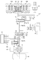
- FIG. 1 is a block diagram showing a schematic configuration of a hybrid vehicle that is an embodiment of a vehicle on which a liquid flow path control device according to the present invention can be mounted. It is a longitudinal cross-sectional view of the rear-wheel drive device controlled with the liquid flow-path control apparatus based on this invention.
- FIG. 3 is a partially enlarged view of the rear wheel drive device shown in FIG. 2. It is a perspective view which shows the state with which the rear-wheel drive device was mounted in the flame
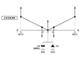
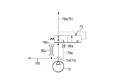
- (A) is explanatory drawing when an oil-path switching valve is located in a low-pressure side position
- (b) is explanatory drawing when an oil-path switching valve is located in a high-pressure side position.
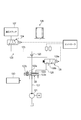
- FIG. 3 is a hydraulic circuit diagram of the hydraulic control device while traveling and in a released state of the hydraulic brake. It is a hydraulic circuit diagram of the hydraulic control device in a weakly engaged state of the hydraulic brake. It is a hydraulic circuit diagram of the hydraulic control device in the engaged state of the hydraulic brake. It is a graph which shows the load characteristic of an electric oil pump.
- FIG. 1 is a hydraulic circuit diagram which shows the 2nd modification of 7th Embodiment.
- (A)-(c) is a hydraulic circuit diagram which shows the 2nd modification of 7th Embodiment. It is a block diagram which shows schematic structure of the hybrid vehicle which is other embodiment of the vehicle which can mount the liquid flow-path control apparatus which concerns on this invention. 2 is a hydraulic circuit diagram described in Patent Document 1. FIG.
- a vehicle drive device to which the hydraulic control device according to the present invention can be applied uses an electric motor as a drive source for driving an axle, and is used, for example, in a vehicle having a drive system as shown in FIG.
- the case where the vehicle drive device is used for rear wheel drive will be described as an example, but it may be used for front wheel drive.
- a hybrid vehicle having a drive device 6 (hereinafter referred to as a front wheel drive device) in which an internal combustion engine 4 and an electric motor 5 are connected in series at the front portion of the vehicle. While power is transmitted to the front wheel Wf via the transmission 7, the power of the driving device 1 (hereinafter referred to as a rear wheel driving device) provided at the rear of the vehicle separately from the front wheel driving device 6 is the rear wheel Wr ( RWr, LWr).
- the electric motor 5 of the front wheel drive device 6 and the electric motors 2A and 2B of the rear wheel drive device 1 on the rear wheel Wr side are connected to the battery 9 via the PDU 8 (power drive unit), and supply power from the battery 9 to the battery 9. Energy regeneration is possible.
- Reference numeral 8 denotes a control device for performing various controls of the entire vehicle.
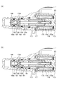
- FIG. 2 is a longitudinal sectional view of the entire rear wheel drive device 1.
- 10A and 10B are left and right axles on the rear wheel Wr side of the vehicle, and are coaxial in the vehicle width direction. Is arranged.
- the reduction gear case 11 of the rear wheel drive device 1 is formed in a substantially cylindrical shape as a whole, and includes an electric motor 2A and 2B for driving an axle, and a planetary gear type reduction gear for reducing the drive rotation of the electric motors 2A and 2B.
- the machines 12A and 12B are arranged coaxially with the axles 10A and 10B.
- the electric motor 2A and the planetary gear type reduction gear 12A control the left rear wheel LWr
- the electric motor 2B and the planetary gear type reduction gear 12B control the right rear wheel RWr
- the electric motor 2A, the planetary gear type reduction gear 12A, the electric motor 2B, planetary gear reducer 12B are disposed symmetrically in the vehicle width direction in the reducer case 11.
- the speed reducer case 11 is supported by the support portions 13 a and 13 b of the frame member 13 that is a part of the frame that is the skeleton of the vehicle 3 and the frame of the rear wheel drive device 1 (not shown).
- the support portions 13a and 13b are provided on the left and right with respect to the center of the frame member 13 in the vehicle width direction.
- the arrow in FIG. 4 has shown the positional relationship in the state in which the rear-wheel drive device 1 was mounted in the vehicle.
- the stators 14A and 14B of the electric motors 2A and 2B are respectively fixed inside the left and right ends of the speed reducer case 11, and annular rotors 15A and 15B are rotatably arranged on the inner peripheral sides of the stators 14A and 14B.
- Cylindrical shafts 16A and 16B surrounding the outer periphery of the axles 10A and 10B are coupled to the inner peripheral portions of the rotors 15A and 15B, and the cylindrical shafts 16A and 16B are decelerated so as to be coaxially rotatable with the axles 10A and 10B.
- the machine case 11 is supported by end walls 17A and 17B and intermediate walls 18A and 18B via bearings 19A and 19B.
- the rotational position information of the rotors 15A and 15B is transmitted to the end walls 17A and 17B of the reduction gear case 11 on the outer periphery on one end side of the cylindrical shafts 16A and 16B, and the control controllers (not shown) of the motors 2A and 2B.
- Resolvers 20A and 20B are provided for feedback.
- the planetary gear speed reducers 12A and 12B include sun gears 21A and 21B, a plurality of planetary gears 22A and 22B meshed with the sun gear 21, planetary carriers 23A and 23B that support the planetary gears 22A and 22B, and planetary gears. Ring gears 24A and 24B meshed with the outer peripheral sides of 22A and 22B, and the driving forces of the electric motors 2A and 2B are input from the sun gears 21A and 21B, and the reduced driving force is output through the planetary carriers 23A and 23B. It is like that.
- Sun gears 21A and 21B are formed integrally with cylindrical shafts 16A and 16B.
- the planetary gears 22A and 22B include large-diameter first pinions 26A and 26B that are directly meshed with the sun gears 21A and 21B, and a second pinion having a smaller diameter than the first pinions 26A and 26B.
- the first and second pinions 26A and 26B and the second pinions 27A and 27B are integrally formed in a state of being coaxially and offset in the axial direction.
- the planetary gears 22A and 22B are supported by the planetary carriers 23A and 23B, and the planetary carriers 23A and 23B are supported so as to be integrally rotatable with the axially inner ends extending inward in the radial direction and being spline-fitted to the axles 10A and 10B.
- the intermediate walls 18A and 18B are supported.
- the intermediate walls 18A and 18B separate the motor housing space for housing the motors 2A and 2B and the speed reducer space for housing the planetary gear type speed reducers 12A and 12B, and the axial distance from the outer diameter side to the inner diameter side. It is configured to bend so as to spread.
- Bearings 33A and 33B for supporting the planetary carriers 23A and 23B are arranged on the inner diameter side of the intermediate walls 18A and 18B and on the planetary gear type speed reducers 12A and 12B, and the outer diameter side of the intermediate walls 18A and 18B.
- bus rings 41A and 41B for the stators 14A and 14B are arranged on the side of the electric motors 2A and 2B (see FIG. 2).
- the ring gears 24A and 24B are disposed opposite to each other at gears 28A and 28B whose inner peripheral surfaces are meshed with the second pinions 27A and 27B having a small diameter, and smaller in diameter than the gear parts 28A and 28B, at an intermediate position of the speed reducer case 11.
- the maximum radii of the ring gears 24A and 24B are set to be smaller than the maximum distance from the center of the axles 10A and 10B of the first pinions 26A and 26B.
- the small diameter portions 29A and 29B are spline-fitted to an inner race 51 of a one-way clutch 50, which will be described later, and the ring gears 24A and 24B are configured to rotate integrally with the inner race 51 of the one-way clutch 50.
- a cylindrical space is secured between the speed reducer case 11 and the ring gears 24A, 24B, and hydraulic brakes 60A, 60B that constitute braking means for the ring gears 24A, 24B are provided in the space portions in the first pinion 26A, 26B overlaps in the radial direction and overlaps with the second pinions 27A and 27B in the axial direction.
- the hydraulic brakes 60A and 60B include a plurality of fixed plates 35A and 35B that are spline-fitted to the inner peripheral surface of a cylindrical outer diameter side support portion 34 that extends in the axial direction on the inner diameter side of the speed reducer case 11, a ring gear 24A, A plurality of rotating plates 36A, 36B that are spline-fitted on the outer peripheral surface of 24B are alternately arranged in the axial direction, and these plates 35A, 35B, 36A, 36B are fastened and released by the annular pistons 37A, 37B. It is like that.
- the pistons 37 ⁇ / b> A and 37 ⁇ / b> B are formed between the left and right dividing walls 39 extending from the intermediate position of the reduction gear case 11 to the inner diameter side, and the outer diameter side support portion 34 and the inner diameter side support portion 40 connected by the left and right division walls 39.
- the pistons 37A and 37B are moved forward by introducing high pressure oil into the cylinder chambers 38A and 38B, and the oil is discharged from the cylinder chambers 38A and 38B.
- the pistons 37A and 37B are moved backward.
- the hydraulic brakes 60A and 60B are connected to an electric oil pump 70 disposed between the support portions 13a and 13b of the frame member 13 described above, as shown in FIG.
- the pistons 37A and 37B have first piston walls 63A and 63B and second piston walls 64A and 64B in the axial direction, and the piston walls 63A, 63B, 64A and 64B are cylindrical. Are connected by inner peripheral walls 65A and 65B. Therefore, an annular space that opens radially outward is formed between the first piston walls 63A and 63B and the second piston walls 64A and 64B. This annular space is formed on the inner periphery of the outer wall of the cylinder chambers 38A and 38B. It is partitioned in the axial direction left and right by partition members 66A and 66B fixed to the surface.
- a space between the left and right dividing walls 39 of the speed reducer case 11 and the second piston walls 64A and 64B is a first working chamber S1 (see FIG. 5) into which high-pressure oil is directly introduced, and the partition members 66A and 66B and the first piston wall
- a space between 63A and 63B is a second working chamber S2 (see FIG. 5) that is electrically connected to the first working chamber S1 through a through hole formed in the inner peripheral walls 65A and 65B.
- the second piston walls 64A and 64B and the partition members 66A and 66B are electrically connected to the atmospheric pressure.
- oil is introduced into the first working chamber S1 and the second working chamber S2 from a hydraulic circuit 71, which will be described later, and acts on the first piston walls 63A and 63B and the second piston walls 64A and 64B.
- the fixed plates 35A and 35B and the rotating plates 36A and 36B can be pressed against each other by the pressure of. Therefore, since the large pressure receiving area can be gained by the first and second piston walls 63A, 63B, 64A, 64B on the left and right in the axial direction, the fixing plates 35A, 35B A large pressing force against the rotating plates 36A and 36B can be obtained.
- the fixed plates 35A and 35B are supported by the outer diameter side support portion 34 extending from the reduction gear case 11, while the rotation plates 36A and 36B are supported by the ring gears 24A and 24B.
- the frictional engagement between the plates 35A, 35B, 36A, and 36B causes a braking force to be applied to the ring gears 24A and 24B, thereby fixing them.
- piston 37A, the fastening by 37B is released, the ring gear 24A, free rotation of 24B is allowed.
- a space is secured between the coupling portions 30A and 30B of the ring gears 24A and 24B facing each other in the axial direction, and only power in one direction is transmitted to the ring gears 24A and 24B in the space to transmit power in the other direction.
- a one-way clutch 50 is arranged to be shut off.
- the one-way clutch 50 has a large number of sprags 53 interposed between an inner race 51 and an outer race 52.
- the inner race 51 is connected to the small diameter portions 29A, 29B of the ring gears 24A, 24B by spline fitting. It is configured to rotate integrally.
- the outer race 52 is positioned by the inner diameter side support portion 40 and is prevented from rotating.
- the one-way clutch 50 is configured to engage and lock the rotation of the ring gears 24A and 24B when the vehicle 3 moves forward with the power of the electric motors 2A and 2B. More specifically, the one-way clutch 50 is engaged when rotational power in the forward direction on the motors 2A, 2B side (rotation direction when the vehicle 3 is advanced) is input to the wheel Wr side. When the rotational power in the reverse direction on the electric motors 2A and 2B is input to the wheels Wr, the non-engagement state is established, and when the rotational power in the forward direction on the wheels Wr is input to the electric motors 2A and 2B, it is not engaged. The engaged state is established when the rotating power in the reverse direction on the wheel Wr side is input to the electric motors 2A, 2B while being engaged.
- the one-way clutch 50 and the hydraulic brakes 60A and 60B are provided in parallel on the power transmission path between the electric motors 2A and 2B and the wheels Wr.
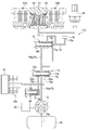
- the hydraulic circuit 71 draws oil sucked from an oil suction port 70 a provided in the oil pan 80 and discharged from the electric oil pump 70 through the oil path switching valve 73 and the brake oil path switching valve 74 and hydraulic brakes 60 ⁇ / b> A and 60 ⁇ / b> B.
- the first working chamber S1 is configured to be capable of refueling, and is configured to be capable of being supplied to the lubrication / cooling unit 91 such as the electric motors 2A, 2B and the planetary gear speed reducers 12A, 12B via the oil path switching valve 73. .
- the electric oil pump 70 can be operated (operated) in at least two modes of a high pressure mode and a low pressure mode by an electric motor 90 composed of a position sensorless brushless DC motor, and is controlled by PID control.
- Reference numeral 92 denotes a sensor that detects the oil temperature and oil pressure of the brake oil passage 77.
- the oil passage switching valve 73 includes a first line oil passage 75a on the electric oil pump 70 side that constitutes the line oil passage 75, and a second line oil passage 75b on the brake oil passage switching valve 74 side that constitutes the line oil passage 75.
- the first oil passage 76 a communicating with the lubrication / cooling section 91 and the second oil passage 76 b communicating with the lubrication / cooling section 91 are connected.
- the oil passage switching valve 73 constantly communicates the first line oil passage 75a and the second line oil passage 75b and selectively communicates the line oil passage 75 with the first oil passage 76a or the second oil passage 76b.
- the valve body 73a, the spring 73b that urges the valve body 73a in a direction (rightward in FIG.
- the urging force of the spring 73b is, as shown in FIG. 6A, the valve body in the oil pressure of the line oil passage 75 that is input to the oil chamber 73c when the electric oil pump 70 is operated in the low pressure mode described later.
- 73a does not move and the line oil passage 75 is cut off from the second oil passage 76b and is connected to the first oil passage 76a (hereinafter, the position of the valve body 73a in FIG. 6A is referred to as a low pressure side position).
- the electric oil pump 70 is operated in a high pressure mode, which will be described later, in the oil pressure of the line oil passage 75 that is input to the oil chamber 73c, as shown in FIG.
- the passage 75 is set so as to be blocked from the first oil passage 76a and communicated with the second oil passage 76b (hereinafter, the position of the valve body 73a in FIG. 6B is referred to as a high pressure side position).
- the brake oil passage switching valve 74 includes a second line oil passage 75b constituting the line oil passage 75, a brake oil passage 77 connected to the hydraulic brakes 60A and 60B, a storage portion 79 via a high position drain 78, Connected to. Further, the brake oil passage switching valve 74 connects and disconnects the second line oil passage 75b and the brake oil passage 77, and shuts off the valve body 74a from the second line oil passage 75b and the brake oil passage 77. Spring 74b urging in the direction (rightward in FIG. 5) and the direction in which the valve body 74a communicates with the second line oil passage 75b and the brake oil passage 77 by the oil pressure of the line oil passage 75 (leftward in FIG.
- valve body 74a is urged by the spring 74b in a direction (to the right in FIG. 5) that blocks the second line oil passage 75b and the brake oil passage 77, and is input to the oil chamber 74c.
- the hydraulic pressure of 75 enables the second line oil passage 75b and the brake oil passage 77 to be pressed in a direction (leftward in FIG. 5).
- the urging force of the spring 74b is the hydraulic pressure of the line oil passage 75 that is input to the oil chamber 74c while the electric oil pump 70 is operating in the low pressure mode and the high pressure mode. 7 (b), the brake oil passage 77 is cut off from the high-position drain 78 and communicated with the second line oil passage 75b. That is, regardless of whether the electric oil pump 70 is operated in the low pressure mode or the high pressure mode, the oil pressure of the line oil passage 75 input to the oil chamber 74c exceeds the urging force of the spring 74b, and the brake oil passage 77 is increased. Shut off from the position drain 78 and communicate with the second line oil passage 75b.
- the hydraulic brakes 60 ⁇ / b> A and 60 ⁇ / b> B are communicated with the storage portion 79 via the brake oil passage 77 and the high position drain 78.
- the reservoir 79 is higher in the vertical direction than the oil pan 80, more preferably, the vertical uppermost portion of the reservoir 79 is the uppermost vertical direction of the first working chamber S1 of the hydraulic brakes 60A and 60B. It arrange
- the brake oil passage switching valve 74 when the brake oil passage switching valve 74 is closed, the oil stored in the first working chamber S1 of the hydraulic brakes 60A and 60B is not directly discharged to the oil pan 80 but is discharged to the storage unit 79. Configured to be stored. The oil overflowing from the reservoir 79 is configured to be discharged to the oil pan 80.
- the storage portion side end portion 78 a of the high position drain 78 is connected to the bottom surface of the storage portion 79.
- the oil chamber 74 c of the brake oil passage switching valve 74 is connectable to a second line oil passage 75 b constituting the line oil passage 75 via a pilot oil passage 81 and a solenoid valve 83.
- the solenoid valve 83 is configured by an electromagnetic three-way valve controlled by the control device 8. When the control device 8 is not energized to the solenoid 174 (see FIG. 8) of the solenoid valve 83, the second line oil passage 75 b is pilot oil. Connected to the path 81, the oil pressure of the line oil path 75 is input to the oil chamber 74c.
- the solenoid valve 83 is provided on a three-way valve member 172 and a case member 173, and is energized by receiving a power supplied via a cable (not shown) and a solenoid 174.
- a solenoid valve body 175 that is pulled right by receiving an exciting force
- a solenoid spring 176 that is housed in a spring holding recess 173a formed at the center of the case member 173, and biases the solenoid valve body 175 leftward
- a guide member 177 which is provided in the direction valve member 172 and slidably guides the advancement / retraction of the solenoid valve body 175.
- the three-way valve member 172 is a substantially bottomed cylindrical member, and includes a right concave hole 181 formed from the right end portion to the substantially middle portion along the center line, and from the left end portion also along the center line.
- a left concave hole 182 formed to the vicinity of the right concave hole 181, and a first radial hole formed along the direction orthogonal to the center line between the right concave hole 181 and the left concave hole 182 183, a second radial hole 184 that communicates with a substantially middle portion of the right concave hole 181 and is formed along a direction orthogonal to the center line, and a left concave hole 182 that is formed along the center line.
- a first axial hole 185 that communicates with the one radial hole 183, and a second axial hole 186 that is formed along the center line and communicates with the first radial hole 183 and the right concave hole 181.
- a ball 187 that opens and closes the first axial hole 185 is placed in the bottom of the left concave hole 182 of the three-way valve member 172 so as to be movable in the left-right direction, and on the inlet side of the left concave hole 182
- a cap 188 for restricting the detachment of the ball 187 is fitted.
- the cap 188 has a through hole 188a that communicates with the first axial hole 185 along the center line.
- the second axial hole 186 is opened and closed by contact or non-contact of the root portion of the opening / closing projection 175a formed at the left end portion of the solenoid valve body 175 that moves left and right.
- the ball 187 that opens and closes the first axial hole 185 is moved to the left and right by the tip of the opening and closing protrusion 175a of the solenoid valve body 175 that moves left and right.
- the solenoid valve body 175 is moved to the left by receiving the urging force of the solenoid spring 176 as shown in FIG. 8A by deenergizing the solenoid 174 (no power supply).
- the tip of the opening / closing protrusion 175a of the solenoid valve body 175 pushes the ball 187, the first axial hole 185 is opened, and the root of the opening / closing protrusion 175a of the solenoid valve body 175 is the second axial hole 186.
- the second axial hole 186 is closed.
- the second line oil passage 75b constituting the line oil passage 75 communicates with the oil chamber 74c from the first axial hole 185 and the first radial hole 183 via the pilot oil passage 81 (hereinafter, FIG. 8).
- the position of the solenoid valve body 175 may be referred to as a valve opening position.
- the solenoid valve body 175 moves to the right against the urging force of the solenoid spring 176 by receiving the exciting force of the solenoid 174 as shown in FIG.
- the oil pressure from the through hole 188a pushes the ball 187
- the first axial hole 185 is closed, and the root portion of the opening / closing protrusion 175a of the solenoid valve body 175 is separated from the second axial hole 186, The second axial hole 186 is opened.
- the oil stored in the oil chamber 74c is discharged to the oil pan 80 through the first radial hole 183, the second axial hole 186, and the second radial hole 184, and the second line oil passage 75b.
- the pilot oil passage 81 are shut off (hereinafter, the position of the solenoid valve body 175 in FIG. 8B may be referred to as a valve closing position).
- the first oil passage 76 a and the second oil passage 76 b merge on the downstream side to form a common oil passage 76 c, and the common oil passage 76 c is formed at the junction.
- a relief valve 84 is connected to discharge the oil in the common oil passage 76c to the oil pan 80 through the relief drain 86 and reduce the oil pressure when the line pressure exceeds a predetermined pressure.
- the first oil passage 76a and the second oil passage 76b are respectively provided with orifices 85a and 85b as flow path resistance means, and the orifice 85a of the first oil passage 76a is formed.
- the second oil passage 76b is configured to have a larger diameter than the orifice 85b. Accordingly, the flow resistance of the second oil passage 76b is larger than the flow resistance of the first oil passage 76a, and the amount of pressure reduction in the second oil passage 76b during operation of the electric oil pump 70 in the high pressure mode is the electric oil pump. 70 is larger than the pressure reduction amount in the first oil passage 76a during operation in the low pressure mode, and the oil pressure in the common oil passage 76c in the high pressure mode and the low pressure mode is substantially equal.
- the oil path switching valve 73 connected to the first oil path 76a and the second oil path 76b has a spring 73b that is more than the oil pressure in the oil chamber 73c when the electric oil pump 70 is operating in the low pressure mode.
- the urging force prevails and the urging force of the spring 73b causes the valve body 73a to be positioned at the low pressure side position, thereby blocking the line oil passage 75 from the second oil passage 76b and communicating with the first oil passage 76a.
- the oil flowing through the first oil passage 76a is reduced in pressure due to the passage resistance at the orifice 85a, and reaches the lubrication / cooling section 91 via the common oil passage 76c.
- the electric oil pump 70 when the electric oil pump 70 is operating in the high pressure mode, the oil pressure in the oil chamber 73c is greater than the urging force of the spring 73b, and the valve element 73a is positioned at the high pressure side position against the urging force of the spring 73b.
- the line oil passage 75 is cut off from the first oil passage 76a and communicated with the second oil passage 76b.
- the oil flowing through the second oil passage 76b is reduced in pressure by the orifice 85b due to a larger passage resistance than the orifice 85a, and reaches the lubrication / cooling unit 91 via the common oil passage 76c.
- the oil passage having the small flow resistance is automatically switched from the oil passage having the small flow resistance to the oil passage having the large flow resistance in accordance with the change in the oil pressure of the line oil passage 75. It is suppressed that excessive oil is supplied to the lubrication / cooling unit 91 in the mode.
- a plurality of orifices 85c are provided as other passage resistance means.
- the plurality of orifices 85c are set so that the minimum flow passage cross-sectional area of the orifice 85a of the first oil passage 76a is smaller than the minimum flow passage cross-sectional area of the plurality of orifices 85c. That is, the flow resistance of the orifice 85a of the first oil passage 76a is set larger than the flow resistance of the plurality of orifices 85c.
- the minimum flow path cross-sectional area of the plurality of orifices 85c is the sum of the minimum flow path cross-sectional area of each orifice 85c.
- the control device 8 (see FIG. 1) is a control device for performing various controls of the entire vehicle.
- the control device 8 is input with vehicle speed, steering angle, accelerator pedal opening AP, shift position, SOC, and the like.
- a signal for controlling the internal combustion engine 4 a signal for controlling the electric motors 2 ⁇ / b> A and 2 ⁇ / b> B, a signal indicating the power generation state / charge state / discharge state of the battery 9, and the solenoid 174 of the solenoid valve 83.
- Control signal, a control signal for controlling the electric oil pump 70, and the like are output.
- control device 8 has at least a function as an electric motor control device for controlling the electric motors 2A, 2B and a function as a connection / disconnection means control device for controlling the hydraulic brakes 60A, 60B as connection / disconnection means.
- Controller 8 as engaging and disengaging means controller controls the solenoid 174 of the electric oil pump 70 and the solenoid valve 83 based on the electric motor 2A, 2B of the driving state and / or the electric motor 2A, 2B drive command (driving signal) .
- the electric oil pump 70 may be controlled by rotational speed control or torque control, and is based on the target hydraulic pressure in the first working chamber S1 and the second working chamber S2.
- the determination is made based on the actual hydraulic pressure and the target hydraulic pressure in the first working chamber S1 and the second working chamber S2 detected from the sensor 92.
- the estimated oil pressure obtained by the oil pressure estimating means may be used.
- the electric oil pump 70 and the hydraulic brakes 60 ⁇ / b> A and 60 ⁇ / b> B are composed of the first line oil passage 75 a on the upstream side of the oil passage switching valve 73, the second line oil passage 75 b on the downstream side, and the brake oil passage 77.
- the hydraulic oil passage is configured to communicate with the first oil passage 75a upstream of the oil passage switching valve 73, the first oil passage 76a, the second oil passage 76b, and the common oil passage 76c.
- a liquid flow path that communicates between the lubrication / cooling section 91 and the lubrication / cooling section 91 is configured, and an oil path switching valve 73 is provided as a flow path switching valve across the hydraulic pressure path and the liquid flow path.
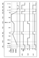
- FIG. 5 shows the hydraulic circuit 71 in a state where the hydraulic brakes 60A and 60B are released while the vehicle is stopped.
- the control device 8 does not operate the electric oil pump 70.
- the valve body 73a of the oil passage switching valve 73 is located at the low pressure side position
- the valve body 74a of the brake oil passage switching valve 74 is located at the valve closing position, and no hydraulic pressure is supplied to the hydraulic circuit 71.
- FIG. 9 shows a state in which the hydraulic brakes 60A and 60B are released while the vehicle is running.
- the control device 8 operates the electric oil pump 70 in the low pressure mode. Further, the control device 8 is energized to the solenoid 174 of the solenoid valve 83, and the second line oil passage 75b and the pilot oil passage 81 are shut off.
- the valve body 74a of the brake oil passage switching valve 74 is positioned at the valve closing position by the urging force of the spring 74b, and the second line oil passage 75b and the brake oil passage 77 are shut off, and the brake oil passage 77 and The high position drain 78 is communicated, and the hydraulic brakes 60A and 60B are released.
- the brake oil passage 77 is connected to the storage portion 79 via a high position drain 78.
- the oil passage switching valve 73 has a valve element whose urging force of the spring 73b is larger than the oil pressure of the line oil passage 75 operating in the low pressure mode of the electric oil pump 70 inputted to the oil chamber 73c at the right end in the figure.
- 73a is positioned at the low pressure side position, and the line oil passage 75 is cut off from the second oil passage 76b and communicated with the first oil passage 76a.
- the oil in the line oil passage 75 is depressurized by the orifice 85 a through the first oil passage 76 a and supplied to the lubrication / cooling unit 91.
- FIG. 10 shows the hydraulic circuit 71 in a state where the hydraulic brakes 60A and 60B are weakly engaged.
- the weak engagement means a state in which power can be transmitted but is fastened with a weak fastening force with respect to the fastening force of the hydraulic brakes 60A and 60B.
- the control device 8 operates the electric oil pump 70 in the low pressure mode. Further, the control device 8 deenergizes the solenoid 174 of the solenoid valve 83 and inputs the hydraulic pressure of the second line oil passage 75 b to the oil chamber 74 c of the brake oil passage switching valve 74.
- the hydraulic pressure in the oil chamber 74c is superior to the urging force of the spring 74b, the valve body 74a is positioned at the valve open position, the brake oil passage 77 and the high position drain 78 are shut off, and the second line oil passage. 75b and the brake oil passage 77 are communicated, and the hydraulic brakes 60A and 60B are weakly engaged.
- the oil path switching valve 73 is operating in the low pressure mode of the electric oil pump 70 in which the urging force of the spring 73b is input to the oil chamber 73c at the right end in the figure, as in the case of releasing the hydraulic brakes 60A and 60B. Therefore, the valve body 73a is positioned at the low pressure side position, and the line oil passage 75 is cut off from the second oil passage 76b and communicated with the first oil passage 76a. As a result, the oil in the line oil passage 75 is depressurized by the orifice 85 a through the first oil passage 76 a and supplied to the lubrication / cooling unit 91.
- FIG. 11 shows the hydraulic circuit 71 in a state where the hydraulic brakes 60A and 60B are engaged.
- the control device 8 operates the electric oil pump 70 in the high pressure mode.
- the control device 8 deenergizes the solenoid 174 of the solenoid valve 83 and inputs the hydraulic pressure of the second line oil passage 75 b to the oil chamber 74 c at the right end of the brake oil passage switching valve 74.
- the hydraulic pressure in the oil chamber 74c is superior to the urging force of the spring 74b
- the valve body 74a is positioned at the valve open position
- the brake oil passage 77 and the high position drain 78 are shut off, and the second line oil passage.
- 75b and the brake oil passage 77 are communicated, and the hydraulic brakes 60A and 60B are fastened.
- the hydraulic pressure of the line oil passage 75 inputted to the oil chamber 73c at the right end in the figure during operation in the high pressure mode of the electric oil pump 70 is larger than the urging force of the spring 73b.
- the line oil passage 75 is cut off from the first oil passage 76a and communicated with the second oil passage 76b. Thereby, the oil in the line oil passage 75 is depressurized by the orifice 85 b through the second oil passage 76 b and supplied to the lubrication / cooling unit 91.
- control device 8 controls the operation mode (operation state) of the electric oil pump 70 and the opening and closing of the solenoid valve 83 to release or fasten the hydraulic brakes 60A and 60B,
- the wheel Wr side can be switched between a disconnected state and a connected state, and the fastening force of the hydraulic brakes 60A and 60B can be controlled.
- FIG. 12 is a graph showing load characteristics of the electric oil pump 70.
- the low pressure mode (hydraulic pressure PL) reduces the power of the electric oil pump 70 to about 1/4 to 1/5 while maintaining the oil supply flow rate. Can be reduced. That is, the load of the electric oil pump 70 is small in the low pressure mode, and the power consumption of the electric motor 90 that drives the electric oil pump 70 can be reduced compared to the high pressure mode.
- FIG. 13 shows the relationship between the front wheel drive device 6 and the rear wheel drive device 1 in each vehicle state, including the operating states of the electric motors 2A and 2B and the state of the hydraulic circuit 71.
- the front unit is a front wheel drive device 6, the rear unit is a rear wheel drive device 1, the rear motor is an electric motor 2A, 2B, EOP is an electric oil pump 70, SOL is a solenoid 174, OWC is a one-way clutch 50, and BRK is a hydraulic brake.
- 60A and 60B are represented.
- the rear wheel drive device 1 performs the rear wheel drive at a low vehicle speed with good motor efficiency such as EV start and EV cruise.
- a low vehicle speed with good motor efficiency such as EV start and EV cruise.
- the electric motors 2A and 2B are driven to rotate in the forward direction, forward torque is applied to the sun gears 21A and 21B.
- the one-way clutch 50 is engaged and the ring gears 24A and 24B are locked.
- the planetary carriers 23A and 23B rotate in the forward direction and travel forward.
- the planetary carrier 23A, the 23B running resistance from the axle 10A, 10B is acting in the opposite direction.
- the ignition is turned on and the torque of the electric motors 2A and 2B is increased, whereby the one-way clutch 50 is mechanically engaged and the ring gears 24A and 24B are locked.
- the electric oil pump 70 operates in the low pressure mode (Lo)
- the solenoid 174 of the solenoid valve 83 is not energized (OFF)
- the hydraulic brakes 60A, 60B Is in a weak fastening state.
- the one-way clutch 50 is engaged and power can be transmitted only by the one-way clutch 50.
- the hydraulic brakes 60A and 60B provided in parallel with the motors are also weakly engaged, and the electric motors 2A and 2B and the wheels Wr are connected to each other, so that forward rotational power input from the electric motors 2A and 2B is temporarily received.
- the fastening force of the hydraulic brakes 60 ⁇ / b> A and 60 ⁇ / b> B at this time is a weak fastening force as compared with deceleration regeneration and reverse travel described later.
- the hydraulic brake 60A By making the fastening force of the hydraulic brakes 60A, 60B when the one-way clutch 50 is engaged smaller than the fastening force of the hydraulic brakes 60A, 60B when the one-way clutch 50 is not engaged, the hydraulic brake 60A , Power consumption for fastening 60B is reduced. Further, in this state, as described above, the oil in the line oil passage 75 is depressurized by the orifice 85a via the first oil passage 76a and supplied to the lubrication / cooling section 91, and the lubrication / cooling section 91 is lubricated and cooled. Has been made.
- the rear wheel driving by the rear wheel driving device 1 changes to the front wheel driving by the front wheel driving device 6.
- the forward torque to travel forward from the axles 10A and 10B acts on the planetary carriers 23A and 23B.
- the clutch 50 is disengaged.
- the electric oil pump 70 operates in the low pressure mode (Lo)
- the solenoid 174 of the solenoid valve 83 is not energized (OFF)
- the hydraulic brakes 60A, 60B Is in a weak fastening state.
- the one-way clutch 50 is disengaged and power transmission is impossible only with the one-way clutch 50.
- the hydraulic brakes 60A and 60B provided in parallel with the clutch 50 are weakly engaged, and the motors 2A and 2B and the wheels Wr can be connected to each other so that the power can be transmitted. Rotational speed control is not required when shifting to the hour.
- the fastening force of the hydraulic brakes 60A and 60B at this time is also a weak fastening force as compared with deceleration regeneration or reverse travel described later.
- the oil in the line oil passage 75 is depressurized by the orifice 85a via the first oil passage 76a and supplied to the lubrication / cooling section 91, and the lubrication / cooling section 91 is lubricated and cooled. Has been made.
- the electric oil pump 70 operates in the high pressure mode (Hi)
- the solenoid 174 of the solenoid valve 83 is deenergized (OFF)
- the hydraulic brakes 60A and 60B are turned on. It is in a fastening state (ON).
- the ring gears 24A and 24B are fixed, and the regenerative braking torque in the reverse direction acts on the motors 2A and 2B, and the motors 2A and 2B perform deceleration regeneration.
- the one-way clutch 50 is disengaged and power transmission is impossible only with the one-way clutch 50.
- the hydraulic brakes 60A and 60B provided in parallel with the clutch 50 are fastened, and the motors 2A and 2B and the wheels Wr can be connected to each other so that the power can be transmitted.
- the motor 2A By controlling 2B to the regenerative drive state, the energy of the vehicle can be regenerated. Further, in this state, is decompressed by the orifice 85b oil line oil passage 75 as described above through the second oil passage 76 b, it is supplied to the lubrication and cooling section 91, the lubrication and cooling of the lubricating and cooling portion 91 Has been made.
- the front wheel drive device 6 and the rear wheel drive device 1 are driven by four wheels.
- the rear wheel drive device 1 is in the same state as the forward low vehicle speed shown in FIG. 15, and the hydraulic circuit 71 is also shown in FIG. It will be in the state shown.
- the front wheel drive device 6 drives the front wheels.
- the front wheel drive device 6 drives the front wheels.
- the forward torque to travel forward from the axles 10A and 10B acts on the planetary carriers 23A and 23B.
- the clutch 50 is disengaged.
- the electric oil pump 70 is operated in the low pressure mode (Lo)
- the solenoid 174 of the solenoid valve 83 is energized (ON)
- the hydraulic brakes 60A and 60B are released ( OFF). Accordingly, the accompanying rotation of the electric motors 2A and 2B is prevented, and the electric motors 2A and 2B are prevented from over-rotating at the high vehicle speed by the front wheel drive device 6.
- the oil in the line oil passage 75 is depressurized by the orifice 85a via the first oil passage 76a and supplied to the lubrication / cooling section 91, and the lubrication / cooling section 91 is lubricated and cooled. Has been made.
- the electric oil pump 70 operates in the high pressure mode (Hi)
- the solenoid 174 of the solenoid valve 83 is deenergized (OFF)
- the hydraulic brakes 60A and 60B are turned on. It will be in a fastening state. Accordingly, the ring gears 24A and 24B are fixed, and the planetary carriers 23A and 23B rotate in the reverse direction to travel backward. Incidentally, the planetary carrier 23A, the 23B running resistance from the axle 10A, 10B is acting in the forward direction.
- the one-way clutch 50 is disengaged and power transmission is impossible only by the one-way clutch 50.
- the hydraulic brakes 60A and 60B provided in parallel with the clutch 50 are fastened, and the electric motors 2A and 2B and the wheels Wr can be connected to each other so that power can be transmitted, and the rotational power of the electric motors 2A and 2B can be maintained. Can reverse the vehicle.
- the rear wheel drive device 1 receives power from the running state of the vehicle, in other words, whether the rotation direction of the motors 2A, 2B is the forward direction or the reverse direction, and from either the motor side 2A, 2B or the wheel Wr side. Accordingly, the engagement / release of the hydraulic brakes 60A, 60B is controlled, and the engagement force is adjusted even when the hydraulic brakes 60A, 60B are engaged.
- FIG. 20 shows an electric oil pump 70 (EOP) when the vehicle is stopped, EV start ⁇ EV acceleration ⁇ engine acceleration ⁇ deceleration regeneration ⁇ medium speed cruise ⁇ acceleration ⁇ high speed cruise ⁇ deceleration regeneration ⁇ stop ⁇ reverse ⁇ stop. ) And one-way clutch 50 (OWC) and hydraulic brakes 60A and 60B (BRK).
- EOP electric oil pump 70
- the electric oil pump 70 is not operated (OFF), the one-way clutch 50 is not engaged (OFF), and the hydraulic pressure is The brakes 60A and 60B maintain a released (OFF) state.
- the accelerator pedal is stepped on, EV start and EV acceleration are performed by the rear wheel drive device 1 by rear wheel drive (RWD).
- the electric oil pump 70 is operated (Lo) in the low pressure mode, the one-way clutch 50 is engaged (ON), and the hydraulic brakes 60A and 60B are in a weakly engaged state.
- ENG traveling is performed by the internal combustion engine 4.
- the one-way clutch 50 is disengaged (OFF), and the electric oil pump 70 and the hydraulic brakes 60A and 60B are maintained as they are.
- deceleration regeneration such as when the brake is stepped on, the electric oil pump 70 operates in the high pressure mode (Hi) while the one-way clutch 50 remains disengaged (OFF), and the hydraulic brakes 60A and 60B are engaged (ON). .
- Hi high pressure mode
- the one-way clutch 50 remains disengaged (OFF)
- the hydraulic brakes 60A and 60B are engaged (ON).
- the state is the same as the above-described ENG traveling.
- the one-way clutch 50 is engaged (ON) again.
- the vehicle speed reaches from the middle vehicle speed range to the high vehicle speed range
- the ENG traveling (FWD) by the internal combustion engine 4 is performed again.
- the one-way clutch 50 is disengaged (OFF), and the hydraulic brakes 60A and 60B are released (OFF) while the electric oil pump 70 is operating (Lo) in the low pressure mode.
- the electric oil pump 70 is not operated (OFF), the one-way clutch 50 is disengaged (OFF), and the hydraulic brakes 60A and 60B are released (OFF).
- the one-way clutch 50 remains disengaged (OFF), the electric oil pump 70 operates (Hi) in the high pressure mode, and the hydraulic brakes 60A and 60B are engaged (ON).
- the electric oil pump 70 is not operated again (OFF), the one-way clutch 50 is disengaged (OFF), and the hydraulic brakes 60A and 60B are released (OFF).
- the hydraulic brakes 60A and 60B are maintained in the weakly engaged state at the time of the forward low vehicle speed and the forward vehicle speed, so that the electric motors 2A and 2B can be used even when the drive torque is temporarily reduced in the electric motors 2A and 2B. It becomes possible to prevent the transmission of power between the side and the wheel Wr side. Further, by setting the hydraulic brakes 60A and 60B to a weakly engaged state and keeping the wheel Wr side and the electric motors 2A and 2B sides capable of transmitting power, the rotational speed control is performed when the electric motors 2A and 2B are shifted to the regenerative drive state. Is no longer necessary.
- the hydraulic brakes 60A and 60B are released to prevent over-rotation of the electric motors 2A and 2B. Since the oil temperature of the hydraulic circuit 71 is sufficiently high at the forward high vehicle speed, the hydraulic brakes 60A and 60B can be fastened even after the shift to deceleration regeneration.
- the oil temperature sensor 71 detects the oil temperature of the hydraulic circuit 71 (step S1), and then the sensor 92 detects the oil pressure (Ps) of the hydraulic circuit 71 (step S2).
- the actual rotational speed (Nact) of the electric oil pump 70 is detected (step S3), and the mode is determined (step S4).
- the mode to be selected corresponds to the vehicle state shown in FIG.
- the stop mode in which the hydraulic brakes 60A and 60B are released in response to the stop state, the forward low vehicle speed, the forward vehicle speed, and the acceleration state Corresponding to the low vehicle speed / acceleration mode in which the hydraulic brakes 60A, 60B are weakly engaged, high vehicle speed mode in which the hydraulic brakes 60A, 60B are released in response to the high vehicle speed state, and hydraulic pressure in response to the deceleration regeneration state It is classified into a regenerative mode in which the brakes 60A and 60B are engaged, and a reverse mode in which the hydraulic brakes 60A and 60B are engaged in response to the reverse state.
- step S5 it is determined whether or not the vehicle is in the stop mode.
- the rotational speed command value (Ncmd) of the electric oil pump 70 is set to zero in order to stop the electric oil pump 70 (step S6).
- the number of rotations of the electric oil pump 70 necessary for supplying a predetermined amount of oil to the lubrication / cooling unit 91 according to the oil temperature ( Nlc) is calculated (step S7).
- step S8 it is determined whether or not the high vehicle speed mode is set.
- the electric motor necessary for supplying a predetermined amount of oil to the lubrication / cooling unit 91 is supplied with the rotational speed command value (Ncmd) of the electric oil pump 70 in order to release the hydraulic brakes 60A and 60B.
- the rotational speed (Nlc) of the oil pump 70 is set (step S9).
- the target hydraulic pressure becomes zero from the low pressure hydraulic pressure (PL)
- the PID correction value becomes negative, and a predetermined amount of oil is supplied to the lubrication / cooling unit 91. It is avoided that the rotational speed (Nlc) of the electric oil pump 70 necessary for supplying the electric oil pump falls below.
- step S10 the target hydraulic pressure (Pt) is calculated (step S10). That is, a predetermined low pressure hydraulic pressure (hydraulic pressure PL in the low pressure mode) in which the hydraulic brakes 60A and 60B are in a weak engagement state is calculated in the low vehicle speed / acceleration mode, and the hydraulic brakes 60A and 60B in the regenerative mode or reverse mode. A predetermined high pressure hydraulic pressure (hydraulic pressure PH in the high pressure mode) that is in the engaged state is calculated.
- a differential pressure ( ⁇ P) obtained by subtracting the hydraulic pressure (Ps) of the hydraulic circuit 71 detected by the sensor 92 from the calculated target hydraulic pressure (Pt) is calculated (step S11), and the PID correction value of the differential pressure ( ⁇ P) is calculated.
- a PID correction value (Pc) is calculated (step S12).
- the rotational speed (Nc1) of the electric oil pump 70 corresponding to the PID correction value (Pc) is calculated based on the conversion relationship obtained in advance (step S13), and a predetermined amount of oil is supplied to the lubrication / cooling unit 91.
- the value obtained by adding the number of rotations (Nc1) of the electric oil pump 70 corresponding to the PID correction value (Pc) to the number of rotations (Nlc) of the electric oil pump 70 necessary for the operation is a command value for the number of rotations of the electric oil pump 70 (Ncmd) is set (step S14).
- a command value for the number of rotations of the electric oil pump 70 (Ncmd) is set (step S14).
- the electric oil pump 70 and the lubrication / cooling unit 91 are communicated when the valve element 73a of the oil passage switching valve 73 is at the low pressure side position and at the high pressure side position. Since the flow resistance of the liquid flow path is different, it is possible to appropriately adjust the oil flow rate to the lubrication / cooling unit 91 and the hydraulic pressure to the hydraulic brakes 60A and 60B at each operation position. Further, it the valve element 73a of the oil passage switching valve 73 when the high-pressure side position, because the valve body 73a is large flow path resistance of the liquid flow path than in the low-pressure side position, oil lubrication and cooling unit 91 Can be prevented from being excessively supplied to the substrate. Further, the hydraulic pressure to the hydraulic brakes 60A and 60B can be appropriately increased.
- the liquid flow path has the 1st oil path 76a and the 2nd oil path 76b arrange
- the oil passage switching valve 73 is configured such that when the valve body 73a is at the low pressure side position, the second oil passage 76b is shut off, and when the valve body 73a is at the high pressure side position, Since the oil passage 76a is cut off, only one of the oil passages is in a communicating state, and the flow passage resistance can be accurately adjusted. Further, by adjusting the flow path resistance of the first oil path 76a and the second oil path 76b with the orifices 85a and 85b as flow path resistance means, the flow path resistance can be easily adjusted. In the above embodiment, the orifices 85a and 85b are exemplified as the flow path resistance means.
- the present invention is not limited to this, and a venturi, a lattice mesh, or the like may be used.
- the first oil path 76a and the second oil are so configured that the flow path cross-sectional area of the second oil path 76b is smaller than the flow path cross-sectional area of the first oil path 76a.
- the passage 76b may be formed, and the first oil passage 76a may be lubricated from the oil passage switching valve 73 in the second oil passage 76b rather than the passage length from the oil passage switching valve 73 to the lubrication / cooling unit 91 in the first oil passage 76a.
- the upstream which is the oil path switching valve 73 side among low pressure oil paths can be made different by arranging them in parallel, and the hydraulic circuit 71 can be simplified by making the downstream side common.
- another orifice 85c is provided on the downstream side of the orifice 85a of the first oil passage 76a and the orifice 85b of the second oil passage 76b and on the upstream side of the lubrication / cooling unit 91, Since the orifice 85a of the first oil passage 76a has a larger flow resistance than the orifice 85c, the flow rate of the first oil passage 76a or the second oil passage 76b can be adjusted by the orifices 85a and 85b.
- flow path resistance means such as a venturi or a lattice mesh may be provided instead of the orifice 85c.
- the reservoir 79 is disposed at a position higher in the vertical direction than the oil pan 80 in which the oil suction port 70a of the electric oil pump 70 is disposed, so that the valve body 74a is opened.
- hydraulic brakes 60A shifts from the position to the closed position, when releasing the 60B, the hydraulic brakes 60A, without being discharged directly to 60B of the oil is the oil pan 80, the oil pan 80 via the high position drain 78 Is also discharged and stored in a storage part 79 disposed at a high position in the vertical direction. Therefore, when the valve body 74a again shifts from the valve closing position to the valve opening position and the hydraulic brakes 60A and 60B are engaged, the return of the hydraulic pressure can be accelerated.
- the reservoir 79 is disposed so as to be at a high position.
- Hydraulic brakes 60A, the first working chamber S1 of 60B has high liquid-tightness for a place that generates oil pressure
- the hydraulic brakes 60A, 60B and high position drain 78 oil also communicated through the state storage unit 79
- the oil discharged to the reservoir 79 can be further reduced by setting the uppermost portion in the vertical direction of the reservoir 79 at a position higher than the midpoint of the first working chamber S1. Accordingly, the hydraulic brakes 60A and 60B can be kept in a state where a certain amount of oil is present, and the hydraulic brakes 60A and 60B can be quickly engaged.
- the storage portion side end portion 78a of the high position drain 78 is connected to the bottom surface of the storage portion 79, so that even if the oil in the storage portion 79 decreases, It can suppress that air mixes in.
- the solenoid valve 83 is configured such that when the power to the solenoid 174 is not supplied (non-energized), the solenoid valve body 175 is positioned at the valve open position, and the oil chamber 74c and the electric oil pump 70 are connected.
- the solenoid valve body 175 is positioned at the closed position when the power is supplied (energized) to the solenoid 174, and the oil chamber 74c and the electric oil pump 70 are shut off.
- the hydraulic pressure can be supplied to the oil chamber 74c and the hydraulic pressure can be adjusted without power consumption, and the hydraulic pressure can be supplied to the hydraulic brakes 60A and 60B and the hydraulic pressure can be adjusted accordingly.
- power consumption can be reduced when the engagement time is longer than the release time of the hydraulic brakes 60A and 60B.
- the oil passage can be shut off immediately when power is supplied.
- the configuration of the hydraulic circuit of the first embodiment is partially changed, and the same members are denoted by the same reference numerals and description thereof is omitted.
- the relief drain 86 of the relief valve 84 is disposed not at the oil pan 80 where the oil suction port 70a of the electric oil pump 70 is disposed but at a position higher in the vertical direction than the oil pan 80. It is different from the hydraulic circuit 71 of the first embodiment in that it is connected to the stored reservoir 79. Further, the oil storage portion side end portion 86 a of the relief drain 86 is disposed at a position higher than the uppermost vertical portion of the storage portion 79.
- the oil storage portion side end 86 a of the relief drain 86 is disposed at a position higher than the vertical uppermost portion of the storage portion 79, the oil flows backward from the storage portion 79 via the relief drain 86 to the oil passage. This can be suppressed.
- the hydraulic circuit 71B of the third embodiment is not provided with the brake oil passage switching valve 74 of the first embodiment, and the brake oil passage 77 is directly in the first radial hole 183 of the solenoid valve 83 (see FIG. 8).
- the connection is different from the hydraulic circuit 71 of the first embodiment.
- the operation mode of the electric oil pump 70 and the energization / non-energization of the solenoid 174 are controlled in the same manner as in the hydraulic circuit 71 of the first embodiment, so that the hydraulic pressure is the same as that of the hydraulic circuit 71 of the first embodiment.
- the brakes 60 ⁇ / b> A and 60 ⁇ / b> B can be controlled to a released state, a weakly engaged state, and an engaged state, and the lubrication / cooling unit 91 can always be lubricated / cooled.
- the brake oil passage switching valve 74 since the brake oil passage switching valve 74 is not provided, the oil in the brake oil passage 77 is easily removed when the brake oil passage 77 is shut off. Instead, the brake oil passage switching valve 74 is omitted.
- the structure can be simplified by reducing the number of parts.
- the hydraulic circuit 71C of the fourth embodiment is not provided with the solenoid valve 83 of the first embodiment, and the oil chamber 74c of the brake oil path switching valve 74 directly forms the line oil path 75. Is different from the hydraulic circuit 71 of the first embodiment.
- the electric oil pump 70 can be operated in three modes, ie, the extremely low pressure mode in addition to the high pressure mode and the low pressure mode, and the urging force of the spring 73b of the oil path switching valve 73 is electrically driven.
- the valve body 73a In the oil pressure of the line oil passage 75 that is input to the oil chamber 73c while the oil pump 70 is operating in the low pressure mode and the extremely low pressure mode, the valve body 73a does not move and the line oil passage 75 is shut off from the second oil passage 76b.
- the valve body 73a moves and the line oil passage 75 is moved.
- the first oil passage 76a is cut off from the first oil passage 76a so as to communicate with the second oil passage 76b.
- the urging force of the spring 74b of the brake oil passage switching valve 74 is such that the valve element 74a does not move in the oil pressure of the line oil passage 75 that is input to the oil chamber 74c while the electric oil pump 70 is operating in the extremely low pressure mode.
- the valve body In the oil pressure of the line oil passage 75 which is set so as to shut off the second line oil passage 75b and the brake oil passage 77 and is inputted to the oil chamber 74c while the electric oil pump 70 is operated in the low pressure mode and the high pressure mode, the valve body is used.
- 74 a is set so that the second line oil passage 75 b and the brake oil passage 77 communicate with each other.
- the electric oil pump 70 is operated in the low pressure mode to make the hydraulic brakes 60A and 60B weakly engaged, and the electric oil pump 70 is operated in the extremely low pressure mode to make the hydraulic brakes 60A and 60B released.
- the same operation as in the first embodiment can be achieved by operating the electric oil pump 70 in the high pressure mode.
- the hydraulic circuit 71 of this embodiment it is necessary to control the electric oil pump 70 in three stages, but by omitting the solenoid valve 83 instead, the number of parts can be reduced and the structure can be simplified.
- the hydraulic circuit 71D of the fifth embodiment is not provided with the brake oil passage switching valve 74 and the solenoid valve 83 of the first embodiment, and the second oil passage in which the brake oil passage 77 directly constitutes the line oil passage 75. It is different from the hydraulic circuit 71 of the first embodiment in that it is connected to 75b.
- the hydraulic brakes 60A and 60B are maintained in a weakly engaged state when the electric oil pump 70 is operated in the low pressure mode, and the hydraulic brakes 60A and 60B are engaged when the electric oil pump 70 is operated in the high pressure mode. Since the hydraulic brakes 60A and 60B cannot be maintained in the released state because they are maintained in the state, the other operations can be performed in the same manner as the hydraulic circuit 71 of the first embodiment.
- the hydraulic brakes 60A and 60B are in the released state in order to prevent the motors 2A and 2B from over-rotating at the forward high vehicle speed as described with reference to FIG. This can be dealt with by changing the reduction ratio of the machine or increasing the permissible rotational speed of the electric motors 2A, 2B. According to the present embodiment, by omitting the brake oil passage switching valve 74 and the solenoid valve 83, the number of parts can be reduced and the structure can be simplified.
- the electric oil pump 70 and the hydraulic brakes 60A and 60B are communicated with each other regardless of the operation of the valve element 73a of the oil passage switching valve 73, so that the liquid is stably supplied to the hydraulic brakes 60A and 60B. Can be supplied.
- this hydraulic circuit 71E two branch paths are formed on the way from the first line oil path 75a to the oil path switching valve 73, and one branch path does not pass through the oil path switching valve 73 and the second line oil path 75b.
- the other branch path is connected to the oil chamber 73c.
- the operation mode of the electric oil pump 70 and energization / non-energization to the solenoid 174 are controlled in the same manner as in the hydraulic circuit 71 of the first embodiment, so that the hydraulic pressure is the same as that of the hydraulic circuit 71 of the first embodiment.
- the brakes 60 ⁇ / b> A and 60 ⁇ / b> B can be controlled to a released state, a weakly engaged state, and an engaged state, and the lubrication / cooling unit 91 can always be lubricated / cooled.
- the second oil passage 76b of the first embodiment is connected to the first line oil passage 75a constituting the line oil passage 75 without passing through the oil passage switching valve 73. Thus, it is different from the hydraulic circuit 71 of the first embodiment.
- the biasing force of the spring 73b is greater than the hydraulic pressure in the oil chamber 73c, and the valve element 73a is positioned at the low pressure side position by the biasing force of the spring 73b.
- the line oil passage 75 is communicated with the first oil passage 76a.
- the oil flowing through the first oil passage 76a is reduced in pressure by receiving the flow resistance at the orifice 85a, and the oil flowing through the second oil passage 76b is reduced in pressure by receiving the flow resistance at the orifice 85b, and joins at the common oil passage 76c.
- the lubrication / cooling section 91 is reached.
- the hydraulic pressure in the oil chamber 73c is greater than the biasing force of the spring 73b, and the valve element 73a is positioned at the high pressure side position against the biasing force of the spring 73b.
- the line oil passage 75 is blocked from the first oil passage 76a.
- the oil flowing through the second oil passage 76b is reduced in pressure by the passage resistance at the orifice 85b, and reaches the lubrication / cooling section 91 through the common oil passage 76c.
- the number of oil passages to the lubrication / cooling section 91 is automatically reduced according to the change in the oil pressure of the line oil passage 75 and the passage resistance is increased.
- the flow rate of the second oil passage 76b can be stably secured regardless of the operation of the valve body 73a.
- the orifice 85a of the first oil passage 76a and the orifice 85b of the second oil passage 76b are both larger in diameter. It may be.
- the oil path switching valve 73 brings the first oil path 76a and the second oil path 76b into a communication state, and the valve body 73a. Since the first oil passage 76a is in the shut-off state when is at the high pressure side position, the passage resistance can be increased by reducing the oil passage to the lubrication / cooling section 91.
- the second oil passage 76b communicates the electric oil pump 70 and the lubrication / cooling unit 91 without passing through the oil passage switching valve 73, so that the second oil passage 76b does not depend on the operation of the valve body 73a. A flow rate can be secured stably.
- the flow path resistance is different between the first oil path 76a and the second oil path 76b, when the valve body 73a of the oil path switching valve 73 is at the low pressure side position and at the high pressure side position.
- the flow rate of oil supplied to the lubrication / cooling unit 91 can be finely adjusted. Further, by adjusting the flow path resistance with the orifices 85a and 85b, the flow path resistance can be easily adjusted.
- the second oil passage 76b is provided with a choke 85c instead of the orifice 85b, and the oil flowing through the second oil passage 76b is caused to flow through the choke 85c.
- the pressure is reduced and the lubricating / cooling unit 91 is reached via the common oil passage 76c.
- the choke 85c is inversely proportional to the product of the oil viscosity coefficient and length. Since the viscosity coefficient of oil has temperature characteristics, the viscosity coefficient is large when the oil temperature is low, and the flow path resistance is large.
- the choke 85c has a small viscosity coefficient when the oil temperature is high, and the flow path resistance exhibits characteristics almost equal to those of the orifice.
- the oil passage switching valve 73 is provided in a liquid flow path that connects the electric oil pump 70 and the lubrication / cooling unit 91. Is different from the hydraulic circuit 71F of the seventh embodiment in that it does not straddle the hydraulic path that communicates the hydraulic brakes 60A and 60B.
- a first oil passage 76 a communicating with the lubrication / cooling unit 91 and a second oil passage 76 b communicating with the lubrication / cooling unit 91 are branched from the line oil passage 75.
- the oil passage switching valve 73 is provided in the first oil passage 76a.
- an orifice 85a is formed in the first oil passage 76a on the downstream side of the oil passage switching valve 73, and an orifice 85b is also formed in the second oil passage 76b.
- the oil passage switching valve 73 when the electric oil pump 70 is operating in the low pressure mode, the oil passage switching valve 73 is in communication with the first oil passage 76a.
- the oil flowing through the first oil passage 76a is reduced in pressure by receiving the flow resistance at the orifice 85a, and the oil flowing through the second oil passage 76b is reduced in pressure by receiving the flow resistance at the orifice 85b, and joins at the common oil passage 76c. Then, the lubrication / cooling section 91 is reached.
- the oil passage switching valve 73 keeps the first oil passage 76a shut off.
- the oil flowing through the second oil passage 76b is reduced in pressure by the passage resistance at the orifice 85b, and reaches the lubrication / cooling section 91 through the common oil passage 76c.
- the number of oil passages to the lubrication / cooling section 91 is automatically reduced according to the change in the oil pressure of the line oil passage 75 and the passage resistance is increased.
- the flow rate of the second oil passage 76b can be stably secured regardless of the operation of the valve body 73a.
- the orifice 85a of the first oil passage 76a and the orifice 85b of the second oil passage 76b are both larger in diameter. It may be the same diameter.
- an orifice 85a may be formed in the first oil passage 76a on the upstream side of the oil passage switching valve 73.
- FIG. 29B illustrates a configuration in which an orifice 85a is formed on the downstream side of the branch path that branches from the first oil path 76a and communicates with the oil chamber 73c.
- FIG. A configuration in which an orifice 85a is formed on the upstream side of a branch path branched from one oil path 76a and communicating with the oil chamber 73c is illustrated.
- FIG. 29C by forming the orifice 85a on the upstream side of the branch path, the pressure input to the oil chamber 73c can be reduced by the amount reduced by the orifice 85a.
- an orifice 85a may be formed inside the oil passage switching valve 73.
- the orifice 85a By forming the orifice 85a inside the oil passage switching valve 73, the orifice 85a can be easily formed.
- an orifice is formed in one of the first oil passage 76a and the second oil passage 76b, and the other has a flow passage resistance by adjusting the cross-sectional area of the oil passage itself. You may adjust.
- the orifice 85b is formed only in the second oil passage 76b, and the first oil passage 76a is not provided with an orifice, and the cross-sectional area of the oil passage itself is adjusted. Thereby, manufacture can be simplified.
- the first oil passage 76 a and the second oil passage 76 b are configured to branch inside the oil passage switching valve 73, and are respectively arranged downstream of the oil passage switching valve 73. Orifices 85a and 85b may be formed. Thereby, the 1st oil passage 76a and the 2nd oil passage 76b can be arranged near.
- the rear wheel drive device 1 of the present embodiment is configured such that the planetary gear type speed reducers 12A and 12B are provided in the two electric motors 2A and 2B, respectively, and the left rear wheel LWr and the right rear wheel RWr are respectively controlled.
- the present invention is not limited to this, and as shown in FIG. 31, one electric motor 2C and one speed reducer 12C may be connected to a differential device (not shown).
- the front wheel drive device 6 may use the electric motor 5 as a sole drive source without using the internal combustion engine 4.
- the shut-off state includes not only the case where the flow path is completely closed, but also includes a mode in which the flow path is restricted with respect to the communication state within a range in which the effects of the present invention are achieved.
- oil was illustrated as a liquid provided for cooling or lubrication, you may use not only this but another liquid.
- the spring 73b as the restoring means has been illustrated, the invention is not limited thereto, and the spring 73b may be configured by a liquid chamber, an electromagnetic valve, or the like.
- Rear wheel drive system (vehicle drive system) 2A, 2B, 2C Electric motor 10A, 10B Axle 12A, 12B Planetary gear type reduction gear 50
- One-way clutch 60A, 60B Hydraulic brake (hydraulic connection / disconnection means) 70 Electric oil pump (liquid supply device) 71, 71A to 71F Hydraulic circuit (hydraulic control device) 73 Oil path switching valve (flow path switching valve) 73a Valve body 73b Spring (restoring means) 73c Oil chamber (liquid chamber) 74 Brake oil passage switching valve 75 Line oil passage 75a First line oil passage 75b Second line oil passage 76a First oil passage (first liquid passage) 76b Second oil passage (second liquid passage) 77 Brake oil passage 85a, 85b Orifice (flow passage resistance means, reduced diameter portion) 85c Choke (channel resistance means, reduced diameter part) 91 Lubrication / cooling section (liquid supply section) LWr Left rear wheel (wheel) RWr Right rear wheel (wheel) S1 first working chamber
Landscapes
- Engineering & Computer Science (AREA)
- Mechanical Engineering (AREA)
- Transportation (AREA)
- General Engineering & Computer Science (AREA)
- Power Engineering (AREA)
- Chemical & Material Sciences (AREA)
- Combustion & Propulsion (AREA)
- Sustainable Energy (AREA)
- Life Sciences & Earth Sciences (AREA)
- Sustainable Development (AREA)
- Physics & Mathematics (AREA)
- Electromagnetism (AREA)
- Fluid Mechanics (AREA)
- Hybrid Electric Vehicles (AREA)
- Control Of Transmission Device (AREA)
- Electric Propulsion And Braking For Vehicles (AREA)
- Multiple-Way Valves (AREA)
- Fluid-Pressure Circuits (AREA)
Priority Applications (6)
| Application Number | Priority Date | Filing Date | Title |
|---|---|---|---|
| EP11819675.7A EP2610526B1 (en) | 2010-08-24 | 2011-06-28 | Liquid flow path control device for drive device for vehicle |
| BR112013004286A BR112013004286A2 (pt) | 2010-08-24 | 2011-06-28 | processo para a preparação de intermediários para a podução de inibidores da nep |
| US13/818,533 US20130152570A1 (en) | 2010-08-24 | 2011-06-28 | Fluid flow path control unit for vehicle drive system |
| JP2012530573A JP5487313B2 (ja) | 2010-08-24 | 2011-06-28 | 車両用駆動装置の液体流路制御装置 |
| RU2013112874/11A RU2532039C1 (ru) | 2010-08-24 | 2011-06-28 | Гидравлический регулятор для системы привода транспортного средства |
| CN2011800401389A CN103069196A (zh) | 2010-08-24 | 2011-06-28 | 车辆用驱动装置的液体流路控制装置 |
Applications Claiming Priority (2)
| Application Number | Priority Date | Filing Date | Title |
|---|---|---|---|
| JP2010-187539 | 2010-08-24 | ||
| JP2010187539 | 2010-08-24 |
Publications (1)
| Publication Number | Publication Date |
|---|---|
| WO2012026204A1 true WO2012026204A1 (ja) | 2012-03-01 |
Family
ID=45723217
Family Applications (1)
| Application Number | Title | Priority Date | Filing Date |
|---|---|---|---|
| PCT/JP2011/064791 WO2012026204A1 (ja) | 2010-08-24 | 2011-06-28 | 車両用駆動装置の液体流路制御装置 |
Country Status (7)
| Country | Link |
|---|---|
| US (1) | US20130152570A1 (pt) |
| EP (1) | EP2610526B1 (pt) |
| JP (1) | JP5487313B2 (pt) |
| CN (1) | CN103069196A (pt) |
| BR (1) | BR112013004286A2 (pt) |
| RU (1) | RU2532039C1 (pt) |
| WO (1) | WO2012026204A1 (pt) |
Cited By (4)
| Publication number | Priority date | Publication date | Assignee | Title |
|---|---|---|---|---|
| CN103707828A (zh) * | 2012-10-05 | 2014-04-09 | 本田技研工业株式会社 | 车辆用驱动装置 |
| WO2015093381A1 (ja) * | 2013-12-17 | 2015-06-25 | Ntn株式会社 | 電動車両の異常検知装置 |
| JP2018159399A (ja) * | 2017-03-22 | 2018-10-11 | 本田技研工業株式会社 | 流体圧回路 |
| JP2018159398A (ja) * | 2017-03-22 | 2018-10-11 | 本田技研工業株式会社 | 流体圧回路 |
Families Citing this family (18)
| Publication number | Priority date | Publication date | Assignee | Title |
|---|---|---|---|---|
| KR101814966B1 (ko) * | 2014-06-10 | 2018-01-04 | 혼다 기켄 고교 가부시키가이샤 | 동력 장치 |
| US9156348B1 (en) * | 2014-07-17 | 2015-10-13 | GM Global Technology Operations LLC | Two axis electric drive |
| SE1550307A1 (sv) * | 2014-09-19 | 2016-03-20 | Borgwarner Torqtransfer Systems Ab | A hydraulic system |
| JP6265184B2 (ja) * | 2015-08-28 | 2018-01-24 | トヨタ自動車株式会社 | 動力伝達装置 |
| JP6268133B2 (ja) | 2015-09-08 | 2018-01-24 | トヨタ自動車株式会社 | 動力伝達装置 |
| FR3041054B1 (fr) * | 2015-09-15 | 2017-09-15 | Hispano-Suiza | Dispositif d'alimentation en huile pour un reducteur a train epicycloidal. |
| JP6319342B2 (ja) * | 2016-02-23 | 2018-05-09 | マツダ株式会社 | エンジンのオイル供給制御装置 |
| JP6637811B2 (ja) * | 2016-03-30 | 2020-01-29 | 本田技研工業株式会社 | 駆動装置 |
| KR101746476B1 (ko) | 2016-05-26 | 2017-06-14 | 주식회사 인팩 | 상시사륜 구동장치의 유압 시스템 |
| DE102016220964A1 (de) * | 2016-10-25 | 2018-04-26 | Schaeffler Technologies AG & Co. KG | Hydraulikkreislauf für einen Hybridantriebsstrang |
| JP6703644B2 (ja) * | 2017-05-31 | 2020-06-03 | 本田技研工業株式会社 | 油圧バルブユニット、鞍乗り型車両 |
| JP6695305B2 (ja) * | 2017-06-12 | 2020-05-20 | 日立建機株式会社 | 作業車両の走行装置 |
| JP6780821B2 (ja) * | 2018-06-15 | 2020-11-04 | Smc株式会社 | 真空エジェクタ及び封止弁ユニット |
| JP2019219008A (ja) * | 2018-06-20 | 2019-12-26 | 本田技研工業株式会社 | 油圧回路 |
| US10889173B2 (en) | 2018-09-19 | 2021-01-12 | Textron Inc. | Powertrain |
| US10589623B1 (en) * | 2018-09-19 | 2020-03-17 | Textron Innovations Inc. | Floating engine powertrain |
| JP7014196B2 (ja) * | 2019-02-28 | 2022-02-01 | 株式会社デンソー | 流路切替装置 |
| US20230087455A1 (en) * | 2020-02-26 | 2023-03-23 | Nissan Motor Co., Ltd. | Electric vehicle and control method thereof |
Citations (6)
| Publication number | Priority date | Publication date | Assignee | Title |
|---|---|---|---|---|
| JPH02275168A (ja) * | 1989-04-13 | 1990-11-09 | Toyota Motor Corp | 自動変速機の潤滑油圧供給装置 |
| JPH03234959A (ja) * | 1990-02-07 | 1991-10-18 | Nissan Motor Co Ltd | 自動変速機の潤滑システム |
| JP2000205301A (ja) * | 1999-01-12 | 2000-07-25 | Mitsubishi Motors Corp | オイル供給装置 |
| JP2006258279A (ja) | 2005-02-16 | 2006-09-28 | Honda Motor Co Ltd | 電動オイルポンプの制御装置 |
| JP2007290656A (ja) * | 2006-04-27 | 2007-11-08 | Honda Motor Co Ltd | 電動車両の油圧回路 |
| JP2010187539A (ja) | 2010-06-01 | 2010-08-26 | Yamaha Motor Electronics Co Ltd | 回転電気機器のステータ |
Family Cites Families (5)
| Publication number | Priority date | Publication date | Assignee | Title |
|---|---|---|---|---|
| SU1537574A1 (ru) * | 1988-02-22 | 1990-01-23 | Минский автомобильный завод | Устройство системы охлаждени гидромеханической передачи |
| JP2680191B2 (ja) * | 1988-12-01 | 1997-11-19 | ツァーンラートファブリーク、フリードリッヒスハーフェン、アクチエンゲゼルシャフト | 流体トルクコンバータの摩擦係合クラッチ制御装置 |
| US5700226A (en) * | 1996-02-20 | 1997-12-23 | Ford Global Technologies, Inc. | Hydraulic lubrication control system for an automatic transmission |
| US7128688B2 (en) * | 2003-04-25 | 2006-10-31 | Jatco Ltd | Hydraulic control for automatic transmission |
| US20080182709A1 (en) * | 2007-01-29 | 2008-07-31 | Gm Global Technology Operations, Inc. | Valve configuration for a lubrication circuit of a latched pump applied clutch transmission |
-
2011
- 2011-06-28 JP JP2012530573A patent/JP5487313B2/ja not_active Expired - Fee Related
- 2011-06-28 EP EP11819675.7A patent/EP2610526B1/en not_active Not-in-force
- 2011-06-28 US US13/818,533 patent/US20130152570A1/en not_active Abandoned
- 2011-06-28 CN CN2011800401389A patent/CN103069196A/zh active Pending
- 2011-06-28 RU RU2013112874/11A patent/RU2532039C1/ru not_active IP Right Cessation
- 2011-06-28 BR BR112013004286A patent/BR112013004286A2/pt not_active IP Right Cessation
- 2011-06-28 WO PCT/JP2011/064791 patent/WO2012026204A1/ja active Application Filing
Patent Citations (6)
| Publication number | Priority date | Publication date | Assignee | Title |
|---|---|---|---|---|
| JPH02275168A (ja) * | 1989-04-13 | 1990-11-09 | Toyota Motor Corp | 自動変速機の潤滑油圧供給装置 |
| JPH03234959A (ja) * | 1990-02-07 | 1991-10-18 | Nissan Motor Co Ltd | 自動変速機の潤滑システム |
| JP2000205301A (ja) * | 1999-01-12 | 2000-07-25 | Mitsubishi Motors Corp | オイル供給装置 |
| JP2006258279A (ja) | 2005-02-16 | 2006-09-28 | Honda Motor Co Ltd | 電動オイルポンプの制御装置 |
| JP2007290656A (ja) * | 2006-04-27 | 2007-11-08 | Honda Motor Co Ltd | 電動車両の油圧回路 |
| JP2010187539A (ja) | 2010-06-01 | 2010-08-26 | Yamaha Motor Electronics Co Ltd | 回転電気機器のステータ |
Non-Patent Citations (1)
| Title |
|---|
| See also references of EP2610526A4 * |
Cited By (6)
| Publication number | Priority date | Publication date | Assignee | Title |
|---|---|---|---|---|
| CN103707828A (zh) * | 2012-10-05 | 2014-04-09 | 本田技研工业株式会社 | 车辆用驱动装置 |
| US9193258B2 (en) | 2012-10-05 | 2015-11-24 | Honda Motor Co., Ltd. | Drive device for vehicle |
| CN103707828B (zh) * | 2012-10-05 | 2016-01-20 | 本田技研工业株式会社 | 车辆用驱动装置 |
| WO2015093381A1 (ja) * | 2013-12-17 | 2015-06-25 | Ntn株式会社 | 電動車両の異常検知装置 |
| JP2018159399A (ja) * | 2017-03-22 | 2018-10-11 | 本田技研工業株式会社 | 流体圧回路 |
| JP2018159398A (ja) * | 2017-03-22 | 2018-10-11 | 本田技研工業株式会社 | 流体圧回路 |
Also Published As
| Publication number | Publication date |
|---|---|
| BR112013004286A2 (pt) | 2017-05-23 |
| JP5487313B2 (ja) | 2014-05-07 |
| EP2610526A1 (en) | 2013-07-03 |
| RU2532039C1 (ru) | 2014-10-27 |
| EP2610526B1 (en) | 2017-04-26 |
| RU2013112874A (ru) | 2014-09-27 |
| EP2610526A4 (en) | 2014-03-26 |
| CN103069196A (zh) | 2013-04-24 |
| JPWO2012026204A1 (ja) | 2013-10-28 |
| US20130152570A1 (en) | 2013-06-20 |
Similar Documents
| Publication | Publication Date | Title |
|---|---|---|
| JP5487313B2 (ja) | 車両用駆動装置の液体流路制御装置 | |
| JP5414636B2 (ja) | 車両用駆動装置 | |
| WO2013005783A1 (ja) | 車両用駆動装置 | |
| JP5344771B2 (ja) | 車両 | |
| US8768551B2 (en) | Vehicle driving apparatus | |
| JP5414731B2 (ja) | 車両 | |
| JP5600633B2 (ja) | 車両用駆動装置及び車両 | |
| JP5707210B2 (ja) | 車両用駆動装置及び車両 | |
| JP5335025B2 (ja) | 車両用駆動装置 | |
| JP2012214176A (ja) | 車両用駆動装置 | |
| JP5197689B2 (ja) | 車両用駆動装置の油圧制御装置 | |
| JP5520993B2 (ja) | 車両用駆動装置 | |
| JP5850641B2 (ja) | 車両 | |
| JP5757767B2 (ja) | 車両用駆動装置 | |
| JP5695957B2 (ja) | 車両用駆動装置 | |
| JP5247776B2 (ja) | 車両用駆動装置の油圧制御装置 | |
| JP6118932B1 (ja) | 駆動装置 | |
| JP5608604B2 (ja) | 車両用駆動装置 | |
| JP2013199978A (ja) | 動力装置 | |
| JP5883690B2 (ja) | 車両用駆動装置 | |
| JP2017180565A (ja) | 液状流体供給システム |
Legal Events
| Date | Code | Title | Description |
|---|---|---|---|
| WWE | Wipo information: entry into national phase |
Ref document number: 201180040138.9 Country of ref document: CN |
|
| 121 | Ep: the epo has been informed by wipo that ep was designated in this application |
Ref document number: 11819675 Country of ref document: EP Kind code of ref document: A1 |
|
| WWE | Wipo information: entry into national phase |
Ref document number: 2012530573 Country of ref document: JP |
|
| REEP | Request for entry into the european phase |
Ref document number: 2011819675 Country of ref document: EP |
|
| WWE | Wipo information: entry into national phase |
Ref document number: 13818533 Country of ref document: US Ref document number: 2011819675 Country of ref document: EP |
|
| NENP | Non-entry into the national phase |
Ref country code: DE |
|
| ENP | Entry into the national phase |
Ref document number: 2013112874 Country of ref document: RU Kind code of ref document: A |
|
| REG | Reference to national code |
Ref country code: BR Ref legal event code: B01A Ref document number: 112013004286 Country of ref document: BR |
|
| ENP | Entry into the national phase |
Ref document number: 112013004286 Country of ref document: BR Kind code of ref document: A2 Effective date: 20130222 |