WO2012026178A1 - 媒体集積装置 - Google Patents
媒体集積装置 Download PDFInfo
- Publication number
- WO2012026178A1 WO2012026178A1 PCT/JP2011/062503 JP2011062503W WO2012026178A1 WO 2012026178 A1 WO2012026178 A1 WO 2012026178A1 JP 2011062503 W JP2011062503 W JP 2011062503W WO 2012026178 A1 WO2012026178 A1 WO 2012026178A1
- Authority
- WO
- WIPO (PCT)
- Prior art keywords
- stacking
- medium
- stacking table
- unit
- stacked
- Prior art date
- Legal status (The legal status is an assumption and is not a legal conclusion. Google has not performed a legal analysis and makes no representation as to the accuracy of the status listed.)
- Ceased
Links
Images


Classifications
-
- B—PERFORMING OPERATIONS; TRANSPORTING
- B65—CONVEYING; PACKING; STORING; HANDLING THIN OR FILAMENTARY MATERIAL
- B65H—HANDLING THIN OR FILAMENTARY MATERIAL, e.g. SHEETS, WEBS, CABLES
- B65H31/00—Pile receivers
- B65H31/04—Pile receivers with movable end support arranged to recede as pile accumulates
- B65H31/12—Devices relieving the weight of the pile or permitting or effecting movement of the pile end support during piling
- B65H31/14—Springs
-
- B—PERFORMING OPERATIONS; TRANSPORTING
- B65—CONVEYING; PACKING; STORING; HANDLING THIN OR FILAMENTARY MATERIAL
- B65H—HANDLING THIN OR FILAMENTARY MATERIAL, e.g. SHEETS, WEBS, CABLES
- B65H43/00—Use of control, checking, or safety devices, e.g. automatic devices comprising an element for sensing a variable
- B65H43/02—Use of control, checking, or safety devices, e.g. automatic devices comprising an element for sensing a variable detecting, or responding to, absence of articles
-
- G—PHYSICS
- G07—CHECKING-DEVICES
- G07D—HANDLING OF COINS OR VALUABLE PAPERS, e.g. TESTING, SORTING BY DENOMINATIONS, COUNTING, DISPENSING, CHANGING OR DEPOSITING
- G07D11/00—Devices accepting coins; Devices accepting, dispensing, sorting or counting valuable papers
- G07D11/20—Controlling or monitoring the operation of devices; Data handling
- G07D11/22—Means for sensing or detection
-
- B—PERFORMING OPERATIONS; TRANSPORTING
- B65—CONVEYING; PACKING; STORING; HANDLING THIN OR FILAMENTARY MATERIAL
- B65H—HANDLING THIN OR FILAMENTARY MATERIAL, e.g. SHEETS, WEBS, CABLES
- B65H2220/00—Function indicators
- B65H2220/09—Function indicators indicating that several of an entity are present
-
- B—PERFORMING OPERATIONS; TRANSPORTING
- B65—CONVEYING; PACKING; STORING; HANDLING THIN OR FILAMENTARY MATERIAL
- B65H—HANDLING THIN OR FILAMENTARY MATERIAL, e.g. SHEETS, WEBS, CABLES
- B65H2511/00—Dimensions; Position; Numbers; Identification; Occurrences
- B65H2511/20—Location in space
-
- B—PERFORMING OPERATIONS; TRANSPORTING
- B65—CONVEYING; PACKING; STORING; HANDLING THIN OR FILAMENTARY MATERIAL
- B65H—HANDLING THIN OR FILAMENTARY MATERIAL, e.g. SHEETS, WEBS, CABLES
- B65H2553/00—Sensing or detecting means
- B65H2553/40—Sensing or detecting means using optical, e.g. photographic, elements
- B65H2553/41—Photoelectric detectors
- B65H2553/412—Photoelectric detectors in barrier arrangements, i.e. emitter facing a receptor element
-
- B—PERFORMING OPERATIONS; TRANSPORTING
- B65—CONVEYING; PACKING; STORING; HANDLING THIN OR FILAMENTARY MATERIAL
- B65H—HANDLING THIN OR FILAMENTARY MATERIAL, e.g. SHEETS, WEBS, CABLES
- B65H2553/00—Sensing or detecting means
- B65H2553/40—Sensing or detecting means using optical, e.g. photographic, elements
- B65H2553/41—Photoelectric detectors
- B65H2553/414—Photoelectric detectors involving receptor receiving light reflected by a reflecting surface and emitted by a separate emitter
-
- B—PERFORMING OPERATIONS; TRANSPORTING
- B65—CONVEYING; PACKING; STORING; HANDLING THIN OR FILAMENTARY MATERIAL
- B65H—HANDLING THIN OR FILAMENTARY MATERIAL, e.g. SHEETS, WEBS, CABLES
- B65H2553/00—Sensing or detecting means
- B65H2553/40—Sensing or detecting means using optical, e.g. photographic, elements
- B65H2553/44—Involving light guide, e.g. optical fibres
-
- B—PERFORMING OPERATIONS; TRANSPORTING
- B65—CONVEYING; PACKING; STORING; HANDLING THIN OR FILAMENTARY MATERIAL
- B65H—HANDLING THIN OR FILAMENTARY MATERIAL, e.g. SHEETS, WEBS, CABLES
- B65H2701/00—Handled material; Storage means
- B65H2701/10—Handled articles or webs
- B65H2701/19—Specific article or web
- B65H2701/1912—Banknotes, bills and cheques or the like
Definitions
- the present invention relates to a medium stacking apparatus, and more particularly to a medium stacking apparatus suitably applied to an automatic transaction apparatus disposed in a financial institution, for example.
- ATMs automatic teller machines
- the customer can perform transactions such as deposit, withdrawal and balance inquiry by performing various operations on various display screens displayed on the automatic transaction apparatus.
- Such an automatic transaction apparatus is equipped with a bill storage / release box for storing and discharging bills.
- the banknote stacking mechanism used in the conventional banknote storage and discharge box is provided with a conveyance path so that banknotes are sent and stacked on the banknote stacking table from the horizontal direction.
- the banknotes sent in the horizontal direction from the transport path are stacked vertically in a horizontal posture on the banknote stacking table.
- JP 2010-128536 A proposes a banknote stacking mechanism in which a banknote stacking table is provided with an inclined surface, and banknotes are stacked on the inclined surface in an inclined posture.
- a banknote stacking table is provided with an inclined surface
- banknotes are stacked on the inclined surface in an inclined posture.
- a stage for stacking banknotes that is, a stacking table is moved up and down by a drive belt or a spring. Therefore, in order to detect whether or not banknotes are stacked on the stacking table, a light emitter-photosensor assembly that forms an optical path in the same direction as the moving direction of the stacking table is provided. However, it is necessary to be able to detect bills.
- the optical sensor is provided so as to form an optical path in a direction different from the moving direction of the integration table, it is not necessary to increase the distance between the light emitter and the optical sensor according to the movement distance of the integration table. Depending on the position of the integration platform, the integration platform does not reach the optical path of the sensor, and the sensor cannot detect the integration platform.
- An object of the present invention is to provide a new and improved medium stacking apparatus.
- Another object of the present invention is to provide a medium stacking device having a simple configuration capable of determining whether or not a medium such as banknotes is stacked regardless of the position of the stacking table.
- a medium stacking apparatus includes a stacking base that at least partially supports a medium to be stacked, an elastic member that movably supports the stacking base in a direction in which the medium is stacked, and a stack that detects a drop of the stacking base Including a table detector.
- the stacking table detection unit may be configured to detect whether or not the stacking table is lowered from a predetermined position.
- the surface of the stacking table may be inclined with respect to the lifting direction of the stacking table.
- the medium accumulating apparatus may further include a medium detecting unit capable of detecting whether or not the medium is accumulated on the accumulation table when the accumulation table is above a predetermined position.
- the medium stacking apparatus may further include a determination unit that determines whether the medium is stacked on the stacking table based on the detection result by the stacking table detection unit and the detection result by the medium detection unit.
- the determination unit is configured to determine that the medium is accumulated on the accumulation table when the accumulation table is lowered from a predetermined position or when it is detected that the medium is accumulated on the accumulation table. Also good.
- the determination unit may also be configured to determine that no medium is accumulated on the accumulation table when it is detected that the accumulation table is above a predetermined position and no medium is accumulated on the accumulation table. .
- the stacking unit detector includes a first set of light emitting units and a light receiving unit that form an optical path in a direction intersecting with the raising / lowering direction of the stacking table, and the medium detecting unit forms an optical path in a direction intersecting with the lifting / lowering direction of the stacking table.
- a second set of light emitting units and light receiving units may be included.
- the stacking table detection unit and the medium detection unit are provided on the same side with respect to the stacking table, and the medium stacking device further includes a first guide for guiding the first optical path to the first set of light receiving units.
- An optical member and a second light guide member that guides the second optical path to the second set of light receiving units may be included.
- the accumulation table may include a light shielding member that blocks the first optical path when the accumulation table is above a predetermined position.
- the integration table may also include a light guide member that guides the first optical path to the first set of light receiving units when the integration table is above a predetermined position.
- the stacking table detector includes a pair of light emitting unit and light receiving unit that form an optical path in a direction crossing the ascending / descending direction of the stacking table, and the medium stacking device descends to a position that blocks the optical path as the stacking table is lowered.
- the light shielding member may be included.
- the stacking table detection unit may be configured to detect whether or not the optical path passes through the medium stacking area of the stacking table and the medium is stacked on the stacking table.
- the medium stacking apparatus may further include a determination unit that determines whether or not the medium is stacked on the stacking table based on the detection result of the stacking table detection unit.
- a medium stacking apparatus having a simple configuration capable of determining whether or not a medium such as banknotes is stacked regardless of the position of the stacking table.
- FIG. 1 A schematic external perspective view of an automatic transaction apparatus according to an embodiment of the present invention, Functional block diagram schematically showing the configuration of the automatic transaction apparatus of the embodiment shown in FIG.
- the schematic functional block diagram which shows the structure of the banknote depositing / withdrawing part in the Example shown in FIG.
- FIG. 10 is a conceptual vertical sectional view showing a state transition when banknotes are stacked on the reject cassette shown in FIG. FIG.
- FIG. 10 is a schematic perspective view of the reject cassette shown in FIG.
- FIG. 10 is a schematic perspective view when banknotes are accumulated in the reject cassette shown in FIG.
- the figure which shows the combination logic of the detection result by each sensor at the time of a judgment part judging the presence or absence of accumulation
- the conceptual vertical sectional view which shows the structure of the rejection cassette which concerns on 2nd Example of this invention
- FIG. 15 is a conceptual vertical sectional view showing a state transition when banknotes are stacked on the reject cassette shown in FIG.
- FIG. 15 is a schematic perspective view of a reject cassette when an additional banknote sensor is arranged in the embodiment shown in FIG. FIG.
- FIG. 17 is a schematic perspective view showing a state when bills are stacked on the reject cassette shown in FIG.
- the conceptual vertical sectional view which shows the structure of the rejection cassette which concerns on 3rd Example of this invention
- FIG. 19 is a conceptual vertical sectional view showing a state transition when banknotes are stacked on the reject cassette shown in FIG.
- FIG. 19 is a schematic perspective view of the reject cassette shown in FIG.
- the conceptual vertical sectional view which shows the structure of the rejection cassette which concerns on the 4th Example of this invention, Explanatory elevation view showing banknotes stacked in a horizontal position, It is explanatory explanatory drawing which shows the banknote integrated
- each of a plurality of constituent elements having substantially the same functional configuration may be identified by adding a different suffix to the same reference numeral.
- three banknote storage cassettes 34 having substantially the same functional configuration are shown in FIG. 3, but when each is individually distinguished, they are displayed as 34A, 34B, 34C. When it is not necessary to distinguish them individually, no suffix is added as in the banknote storage cassette 34, for example.
- a medium to be stacked on a stacking table described later is a banknote, but this is only an example, and the present invention is not limited to such an embodiment.
- the media collected on the stacking table are, for example, magnetic cards such as cash cards and credit cards, or IC (integrated circuit) cards, bank passbooks, securities, transportation and event use tickets, that is, tickets, boarding tickets. , Boarding pass, admission ticket, coupon ticket.
- FIG. 1 is a schematic external perspective view of an automatic transaction apparatus according to an embodiment of the present invention.
- the automatic transaction apparatus 1 includes an operation / display unit 10, a card / statement handling unit 11, a passbook handling unit 12, a banknote deposit / withdrawal unit 13, and a coin deposit / withdrawal unit 14.
- the automatic transaction apparatus 1 is installed in various places such as a bank or a station premises.
- the automatic transaction apparatus 1 is connected to a central processing system such as a server of a financial institution or a host computer via a communication network 501 (FIG. 2).
- a communication network 501 FIG. 2.
- the operation / display unit 10 of the automatic transaction apparatus 1 has a function of displaying a display screen for guiding the operation to the customer and a function of receiving an input by the customer's manual operation.
- the operation / display unit 10 may include a touch panel that detects an input to the screen and receives an input as a function of receiving an operation input.
- the card / statement handling unit 11 is a paper strip on which a magnetic card or an IC card such as a cash card used for transactions or an IC card, that is, a plastic card (not shown) is inserted or ejected, and the transaction details are recorded. In other words, it is a functional unit from which a statement slip (also not shown) is discharged.
- the bankbook handling unit 12 is a functional unit in which a bankbook (not shown) used for transactions is inserted or discharged.
- the banknote deposit / withdrawal unit 13 is a functional unit that deposits / withdraws banknotes.
- the coin deposit / withdrawal unit 14 is a functional unit that deposits / withdraws coins.
- the bill deposit / withdrawal unit 13 and the coin deposit / withdrawal unit 14 are provided with shutters (both not shown) that are driven by a drive unit and mechanically shielded from the outside.
- FIG. 2 is a schematic functional block diagram showing the configuration of the automatic transaction apparatus 1 according to the embodiment shown in FIG.
- the automatic transaction apparatus 1 includes a control unit 15 in addition to an operation / display unit 10, a card / detail handling unit 11, a passbook handling unit 12, a banknote depositing / withdrawing unit 13, and a coin depositing / withdrawing unit 14.
- a fixed disk device (HDD) 16 a clerk operation unit 17, a vein authentication device 18, and a communication unit 19.
- the operation / display unit 10 includes functions as a display unit that displays a display screen for guiding operations to a customer and a customer operation unit that detects a customer's manual operation.
- the function as the display unit is realized by, for example, a cathode ray tube (CRT) display device, a liquid crystal display (LCD) device, or an organic light emitting diode (OLED) device.
- the function as the customer operation unit is realized by, for example, a touch panel or a mechanical button (not shown).
- the function of a display part and a customer operation part may be isolate
- the card / detail slip handling unit 11 reads the data recorded on it from a magnetic card or IC card such as a cash card brought by the customer, prints the transaction details on a paper strip, issues a transaction slip and discharges it. It is a functional part to do.
- the bankbook handling unit 12 is a functional unit that prints the contents of transactions made in the automatic transaction apparatus 1 on a bankbook inserted by a customer.
- the banknote depositing / withdrawing unit 13 is a functional unit that counts the number of banknotes to be returned to the customer and the number of banknotes to be withdrawn at the time of the withdrawal transaction, and transports the banknotes to a position where the banknotes can be taken out by the customer.
- the banknote deposit / withdrawal unit 13 also has a function of inspecting banknotes deposited by a customer at the time of deposit transaction, counting the number of each banknote type, and storing it in the automatic transaction apparatus 1.
- the coin deposit / withdrawal unit 14 is a functional unit that inspects the coins deposited by the customer at the time of deposit transaction, counts the number of each coin type, and stores it in the automatic transaction apparatus 1.
- the coin deposit / withdrawal unit 14 also counts the number of coins to be withdrawn for each type at the time of a withdrawal transaction, and transports the coins to a position where they can be taken out by the customer.
- the control unit 15 has an overall control function for comprehensively controlling the operation of the entire automatic transaction apparatus 1.
- the control unit 15 has a function as, for example, a communication control unit that controls communication between the communication unit 19 and a host computer (not shown) and a display control unit that controls a display screen displayed by the operation / display unit 10.
- the control unit 15 further includes a determination unit 20, which responds to detection results of an integration table sensor 37 and a medium sensor 38 (FIG. 3), which will be described later, and an integration table 164 (FIG. 10) inside the reject cassette 35. It is a function part which judges whether the banknote is accumulated in. Details of the determination unit 20 will be described later with reference to FIG.
- the fixed disk device (HDD) 16 is a storage device in which control programs and files necessary for operating the automatic transaction apparatus 1 are stored.
- the clerk operation unit 17 is an clerk interface, and has a function of displaying information such as a failure or failure of each part in the apparatus, and a function of accepting an operation by a clerk to deal with a failure or failure of each part.
- the vein authentication device 18 is an authentication device for performing identity verification.
- the vein authentication device 18 reads the vein pattern of the palm of the customer, and the read vein pattern and the cash card inserted by the customer into the card / detail slip handling unit 11 The identity of the customer is confirmed by comparing the vein pattern registered in advance with the above IC chip (not shown).
- the communication unit 19 is an interface with the host computer, and transmits and receives information necessary for transactions with the host computer via the communication line 501.
- the information necessary for the transaction includes, for example, customer information such as a customer account number, personal identification number and deposit balance, information indicating transaction details such as a deposit amount and a withdrawal amount.
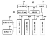
- FIG. 3 is a schematic functional block diagram showing a configuration example of the banknote deposit / withdrawal unit 13.
- the banknote deposit / withdrawal unit 13 includes a customer service unit 31, a discrimination unit 32, a temporary storage unit 33, banknote storage cassettes 34A, 34B and 34C, a reject cassette 35, a forgotten collection container 36, and a stacking table sensor 37. And a bill sensor 38.
- the customer service unit 31 functions as a depositing unit that separates banknotes set by the customer one by one at the time of deposit transaction and transports them to the discrimination unit 32, for example.
- the customer service section 31 also accumulates banknotes to be returned to the customer and banknotes to be withdrawn to the customer during a withdrawal transaction.
- the discrimination unit 32 discriminates the authenticity, type, and correctness of the banknotes that are brought in from the customer service unit 31, detects the conveyance abnormality, and counts the number of banknotes whose types are determined.
- the type of banknote is the value type of banknotes distributed in the same area, such as a thousand yen bill, a 5,000 yen bill, and a 10,000 yen bill.
- the temporary holding unit 33 is a functional unit that temporarily holds the banknotes identified as being acceptable by the discrimination unit 32 at the time of deposit transaction until the deposit is confirmed.
- the banknote storage cassettes 34A, 34B and 34C are storages for storing banknotes deposited by the customer in the customer service section 31. Also, banknotes to be paid to the customer are stored in the banknote storage cassettes 34A, 34B and 34C and taken out therefrom.
- the reject cassette 35 is a storage unit that stores banknotes identified as collected banknotes that are not delivered to the customer by the discrimination unit 32 at the time of a withdrawal transaction or a deposit transaction.
- the discrimination unit 32 may be configured to, for example, discriminate a denomination banknote, a specific type of banknote, a damaged banknote, or a dirty banknote as a recovered banknote.
- the banknotes stored in the reject cassette 35 are later taken out and collected by the operator.
- the automatic transaction apparatus 1 which has such a rejection cassette 35 and the rejection cassette 35 is characteristic of the automatic teller machine which accumulate
- the forgotten collection warehouse 36 is a storage for storing banknotes that the customer forgot to collect at the time of a withdrawal transaction and a deposit transaction.
- the stacking table sensor 37 is a photodetector that detects the stacking table 164 (FIG. 10) on which banknotes inside the reject cassette 35 are stacked.
- the bill sensor 38 is a photodetector that detects whether or not bills are stacked on the stacking table 164 inside the reject cassette 35.
- FIG. 4A is a schematic vertical sectional view showing the configuration of the reject cassette 100 according to Comparative Example 1.
- the reject cassette 100 includes a drive roller 101, an idle roller 102, a stacking table 104, and a stage spring 103.
- the residual sensor 201 which is a combination of the light emitting unit 201a and the light receiving unit 201b, and the light emitting unit 202a are received outside the reject cassette 100.
- a residual sensor 202 configured by a combination of the units 202b is provided.
- the reject cassette 100 is a cassette dedicated to stacking that does not feed out the stacked media again, no electrical components are arranged in the media stacking space 105, and a residual sensor is provided outside as shown in FIG. 4A. 201 and 202 are provided. Since the reject cassette 100 may store half-folded bills, it is necessary to provide a plurality of residual sensors 201 and 202 in this way to detect a plurality of locations on the stacking table 104.
- the bills 301 are drawn into the cassette 100 from the transport path (not shown) by the driving roller 101 and the idle roller 102 and are stacked on the stacking table 104.
- the stacking table 104 is supported by the stage spring 103, and descends in the direction of the arrow 107 by the weight of the stacked bills 301 (FIG. 4B) while being guided by a slide groove and a shaft (not shown).
- Residual sensors 201 and 202 provided in reject cassette 100 form optical paths 109 and 111 in substantially the same direction as the movement direction of stacking stage 104, and these optical paths 109 and 111 correspond to corresponding positions on stacking stage 104. Are disposed so as to pass through the optical through holes 113 and 115 established in the above. Accordingly, the optical path 109 or 111 is blocked as long as the banknotes 301 are stacked on the stacking table 104 regardless of the position in the vertical direction 107, that is, the height, so that the banknote 301 is placed inside the cassette 100. Can be determined to exist.
- FIG. 5A is a schematic vertical sectional view showing the configuration of the reject cassette 110 according to Comparative Example 2.
- the optical that refracts the optical path 109 and guides the light as shown in the figure.
- the prism 112 can be provided in the stacking table 104, and the optical path 109 can be blocked by the banknote 301 as shown in FIG. 5B. Thereby, the number of sensors and mounting space can be reduced, and the apparatus can be miniaturized.
- the reject cassettes 100 and 110 in each of the comparative examples described above have the width of the reject cassette corresponding to the side of the banknote 301 in the transport direction when viewed from the stacking direction 107 of the banknote 301, that is, from above in these drawings. And the width of the larger one of the driving roller and the idle roller and the width of the bill storage part (stacking stand) must be equal to each other, and there is a restriction on downsizing.
- Comparative Example 3 As shown in FIG. 6A, the banknote stacking surface of the stacking table 124 is inclined, and the banknote 301 transported from a transport path (not shown) provided above the reject cassette 120 is As shown in FIG. 6B, they are stacked up and down in an oblique posture along this inclined surface.
- the rejection cassette 120 has few restrictions on the reduction
- the residual sensor 221 including the light emitting unit 221a and the light receiving unit 221b, and the residual sensor 222 including the light emitting unit 222a and the light receiving unit 222b are moved in the same direction as the movement of the stacking base 124, that is, the lifting direction 107, respectively. 111 is provided.
- the stacking table 104 is in the vertical direction 107, if the bills 301 are stacked on the stacking table 124, the optical path 109 or 111 is blocked. It can be determined that the banknote 301 exists inside.
- the sensitivity of the residual sensor 231 is sufficient.
- the thin reject cassettes 130 and 140 in Comparative Example 3 and Comparative Example 4 described above are configured to stack the banknotes 301 in an inclined posture. With such an accumulation of inclined postures, the width of the necessary accumulation space 105 is reduced, and a thin reject cassette can be realized.
- the height of the accumulation space 105 required when accumulating in an inclined posture will be described in comparison with the case of accumulating in a horizontal posture.
- the height of the accumulation space required when accumulating in a horizontal posture will be described with reference to FIG.
- the height of the stacking space 105 required to stack the banknotes 301 in a horizontal posture is naturally equal to the height H at which the banknotes 301 are stacked.
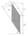
- the height of the accumulation space 105 required when the same number of banknotes 301 as in the example shown in FIG. 23 is accumulated in an inclined posture will be described with reference to FIG.
- the height of the accumulation space required when the banknotes 301 are accumulated at the inclination angle ⁇ is obtained by the following equation (1).
- the thin reject cassettes 120 and 130 that stack the banknotes 301 in an inclined posture can narrow the width of the stacking space 105 as the angle ⁇ for tilting the banknotes 301 increases, but the height of the stacking space 105 increases as the angle ⁇ increases. Need to be high. Therefore, in the thin reject cassette 120 that is short in the width direction and long in the height direction, the optical paths 109 and 111 formed by the residual sensors 221 and 222, respectively, are shown in FIG. 4A by the length indicated by the broken lines 109a and 111a in FIG. The distance between the light emitting part and the light receiving part becomes longer than that. If it does so, since an expensive highly sensitive sensor is needed, there existed a problem of leading to a cost increase.
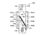
- the residual sensor 241 is arranged so as to form the optical path 109 from the light emitting unit 241a to the light receiving unit 241b in a direction different from the movement of the stacking table 144, that is, the ascending / descending direction 107 (FIG. 8B).
- This solves the above-mentioned problem.
- the reject cassette 140 when the optical path 109 formed by the residual sensor 241 is not blocked by the banknote 301, it is determined that there is no banknote.
- the amount of lowering of the stacking table 144 is not less than the design value, and the banknotes 301 are stacked, as shown in FIG. 8B.
- the banknote 301 may determine that there is no stacked banknote without blocking the optical path 109.
- a plurality of optical paths 109, 111, 118, and 119 are formed in the moving range of the stacking table 144, so that the stacking table 144 is located at any position. The presence or absence of the stacked banknote 301 can be detected.
- an actuator (not shown) for moving the stacking table 144 up and down is added to control the height position of the upper surface of the stacked banknotes 301 so that it is applied to the optical path 109 formed by the residual sensor.
- the inventor came up with the present invention from the viewpoint of these circumstances.
- the embodiment of the present invention it is possible to determine whether or not the medium is stacked on the stacking table by detecting the descent of the stacking table on which banknotes are stacked.
- examples of the present invention will be described in detail.
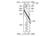
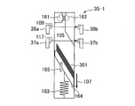
- FIG. 10 is a schematic vertical cross section showing the configuration of the reject cassette 35-1 according to the first embodiment of the present invention.
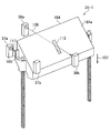
- FIG. 12 is a simplified perspective view of the reject cassette 35-1 in the embodiment shown in FIG.
- the reject cassette 35-1 according to the present embodiment includes a drive roller 161, an idle roller 162, a stage spring 163, a stacking table 164, and a stage detector 165.
- a bill sensor 38 including a pair of a light emitting unit 38a and a light receiving unit 38b that forms an optical path 109 in a direction intersecting the moving direction 107 of the stacking table 164 and detects the presence or absence of the stacked bills 301.
- an integration table sensor 37 including a pair of a light emitting unit 37a and a light receiving unit 37b for detecting the lowering of the integration table 164 is further provided outside the reject cassette 35-1.
- the driving roller 161 and the idle roller 162 are feeding members that draw the banknote 301 from a conveyance path (not shown).
- the stage spring 163 is an elastic member that supports the stacking table 164.
- FIG. 10 shows one stage spring 163 as an example of the elastic member, the present invention is not limited to such an example.
- a plurality of springs may be provided as elastic members that support the stacking table 164.
- FIG. 10 shows an example in which a spring is used as the elastic member, but it can be used as various elastic members that are elastically deformed by the load of the bill.
- the stacking table 164 has an inclined surface 164a that is tilted with respect to the lifting direction 107 of the stacking table 164.
- the inclined surface 164a only needs to support at least a part of the bills 301 (FIG. 11A) accumulated thereon, that is, it may be partially open or net-like. A flat surface is preferable.
- the bills 301 (FIG. 13) drawn by the driving roller 161 and the idle roller 162 are accumulated on the inclined surface 164a.
- the stage spring 163 is compressed by the weight of the stacked banknotes 301. That is, when the bills 301 are stacked on the stacking table 164, the stacking table 164 supported by the stage spring 163 descends in the direction of the arrow 107 as the stage spring 163 is compressed.
- the stage detector 165 is fixed to the stacking table 164 at a position outside the area where the banknotes 301 are stacked and does not block the optical path 109 formed by the banknote sensor 38. That is, the stage detector 165 moves in the ascending / descending direction 107 together with the stacking table 164.
- the stage detector 165 is provided at a position that blocks the optical path 117 formed by the stacking table sensor 37 when the stacking table 164 is at a predetermined height position in the ascending / descending direction 107, that is, above the predetermined position.
- the predetermined position may be, for example, the initial position of the stacking table 164, or may be a height position taken when the banknotes 301 are substantially not stacked.
- the reject cassette 35-1 includes a stage detector 165 provided on the stacking table 164 when the stacking table 164 is above a predetermined position.
- the optical path 117 to be formed is configured to be blocked.
- the stage detector 165 is also moved down together with the stacking table 164, so that the optical path 117 formed by the stacking table sensor 37 is not blocked by the stage detector 165. In this manner, whether or not the stacking table 164 has been lowered from the predetermined position can be detected based on whether or not the optical path 117 formed by the stacking table sensor 38 is blocked by the stage detector 165.
- the banknote sensor 38 includes the light emitting unit 38a and the light receiving unit 38b as described above. As shown in FIG. 12, the light emitting unit 38a and the light receiving unit 38b are arranged to face each other with the stacking table 164 interposed therebetween. As can be seen from the figure, when the banknote 301 is not stacked on the stacking table 164 and the stacking table 164 is in the uppermost position within the range that can be raised and lowered, that is, the initial position, it is formed from the light emitting unit 38a toward the light receiving unit 38b.
- the optical path 109 passes through an optical slit 113 provided in the stacking table 164.
- the optical path 109 formed from the light emitting unit 38a toward the light receiving unit 38b is such that the stacking table 164 is at least from the predetermined position described above. If it is located above, it is blocked by those bills 301. In this way, the reject cassette 35-1 can detect that the banknote 301 is stacked on the stacking table 164 by the banknote sensor 38 when the stage detector 165 is at a position that blocks the optical path 117 formed by the stacking table sensor 37. It is configured.
- the stacking table 164 is optically transparent at least in part, that is, in the present embodiment, where the optical slit 113 is opened, but may be entirely transparent.
- the determination unit 20 determines whether or not banknotes 301 are stacked on the stacking table 164 inside the reject cassette 35-1 based on the detection results of the stacking table sensor 37 and the medium sensor 38 described above. to decide.
- the determination function by the determination unit 20 will be described in detail with reference to FIG.
- FIG. 14 shows the detection results of the stacking table sensor 37 and the banknote sensor 38 and the determination logic by the determination unit 20.
- the sensors 37 and 38 are optical sensors, when the light 109 and 111 emitted from the light emitting units 37a and 38a are received by the light receiving units 37b and 38b, the detection result is “bright”, respectively.
- the detection result becomes “dark”.
- the determination unit 20 determines that the banknotes 301 are stacked on the stacking table 164. to decide. That is, when the stacking table sensor 37 detects that the stacking table 164 is lowered from a predetermined position, or when the banknote sensor 38 detects stacking of the bills 301, the determination unit 20 detects the banknote on the stacking table 164. It is determined that 301 is accumulated.
- the determination unit 20 does not stack the banknotes 301 on the stacking table 164. Judge. That is, if the stacking table sensor 37 detects that the stacking table 164 is above a predetermined position and the banknote sensor 38 does not detect the stacking of the banknotes 301, the determination unit 20 determines that the banknote 301 is on the stacking table 164. Judge that it is not accumulated.
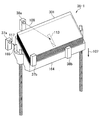
- FIG. 11A to FIG. 11C the state transition of the process of stacking the bills 301 on the reject cassette 35-1, that is, the descending movement process of the stacking table 164 will be described.
- These drawings are conceptual vertical sectional views specifically illustrating state transitions when the bills 301 are stacked on the reject cassette 35-1.
- the stacking table 164 in the reject cassette 35-1 is pushed up to the initial position by the stage spring 163 as shown in FIG. Thereafter, when the banknote 301 is stacked on the stacking table 164, the optical path 109 formed by the banknote sensor 38 is blocked by the banknote 301 as shown in FIG. 11A. Even if the stacking table 164 is slightly lowered due to the weight of the stacked bills 301, if the stacking table 164 is above a predetermined position, the optical path 109 formed by the stacking table sensor 37 is blocked by the stage detector 165. At this time, since the detection results of both the stacking table sensor 37 and the bill sensor 38 indicate “dark”, the determination unit 20 determines that the bills 301 are stacked on the stacking table 164 according to the logical relationship illustrated in FIG. To do.
- the stacking table 164 is further lowered from the normal state, and the optical path 109 formed by the bill sensor 38 is formed. May not be blocked by the banknote 301.
- the determination unit 20 determines that the banknote 301 is stacked on the stacking table 164 according to the logical relationship shown in FIG. to decide.
- the stacking table 164 is pushed up to a stopper (not shown) again by the repulsive force of the stage spring 163, and is initialized. Return to position.
- the optical path 117 formed by the integrated stage sensor 37 is blocked by the stage detector 165.
- the optical path 109 formed by the banknote sensor 38 is not blocked by the banknote 301. Therefore, since the detection result by the stacking table sensor 37 indicates “dark” and the detection result by the banknote sensor 38 indicates “bright”, the determination unit 20 stacks the banknote 301 on the stacking table 164 according to the logical relationship illustrated in FIG. Judge that it is not.
- the determination unit 20 determines that there is a bill whenever the stacking table 164 is lowered from a predetermined position.
- the banknote 301 may be stacked on the stacking table 164 even when the stacking table 164 is not lowered from a predetermined position.
- a bill sensor 38 configured to detect whether or not the bills 301 are stacked on the stacking table 164 when at least the stacking table 164 is above the predetermined position is provided. As a result, the presence / absence of the stacked banknote 301 can be determined more accurately.
- the determination unit 20 determines the position of the stacking table 164 and the banknote stacking state. Regardless, the presence / absence of the stacked banknote 301 can be correctly determined.
- the present embodiment it is not necessary to provide a plurality of sensors 251 corresponding to the raising / lowering direction 107 of the stacking table 144 as in the comparative example 6 shown in FIG.
- the presence or absence of the stacked banknotes 301 can be determined, which reduces the cost of the entire apparatus.
- This embodiment also eliminates the need to form the optical path 109 of the sensor parallel to the ascending / descending or stacking direction 107 of the stacking table 164. Therefore, the thin cassette 120 as in Comparative Example 3 in which the bills 301 are stacked in an inclined posture (FIG. 6A). ) Does not increase the distance between sensors. Therefore, an inexpensive sensor can be used without using an expensive long-distance sensor.
- the optical path 109 of the sensor can be formed in a direction different from the raising / lowering direction 107 of the stacking table 164, the sensor optical path is not affected by the driving roller 161, the idle roller 162, etc. Can be arranged.
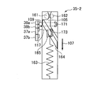
- FIG. 15 is a schematic vertical sectional view showing the configuration of the reject cassette 35-2 according to the second embodiment of the present invention.
- the reject cassette 35-2 according to the present embodiment includes a first prism 171 and a second prism in addition to the drive roller 161, the idle roller 162, the stage spring 163, the stacking table 164, and the stage detector 165.
- the prism 173 is provided.
- a bill sensor 38 including 38b is provided outside the reject cassette 35-1.
- an integrated table sensor 37 including a set of light emitting unit 37a and light receiving unit 37b for detecting the lowering of the integrated table 164 is provided outside the reject cassette 35-1.
- the driving roller 161, the idle roller 162, the stage spring 163, the stacking table 164, and the stage detector 165 may be the same as those in the first embodiment described above, and the description thereof is omitted.
- the first prism 171 is an optical element having a side shape as shown that refracts the light 109 emitted from the light emitting part 38a of the banknote sensor 38 and guides it to the light receiving part 38b.
- the second prism 173 is an optical element having a side shape as shown in the figure, which refracts the light 111 emitted from the light emitting part 37a of the integrated table sensor 37 and guides it to the light receiving part 37b.
- Each prism 171 and 173 may be fixedly provided at a location not interlocked with the stacking table 164, for example, the casing of the cassette 35-2.
- the prisms 171 and 173 for guiding the light 109 and 111 are provided on one side of the reject cassette 35-2.
- the mounting space for the sensors 37 and 38 is about half that of the first embodiment, and the entire apparatus can be further downsized.
- the bill sensor 38 can form the two optical paths 109 intersecting the moving direction 107 of the stacking table 164 with a single sensor by using the first prism 171. As a result, the number of sensors can be further reduced, and therefore the cost of the entire apparatus can be reduced.
- the determination unit 20 shown in FIG. 2 determines whether or not the bills 301 are stacked on the stacking table 164 inside the reject cassette 35-2 based on the detection results of the stacking table sensor 37 and the medium sensor 38 described above. As the determination logic by the determination unit 20, the logical relationship shown in FIG. 14 is applied as it is.
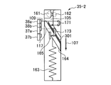
- FIGS. 16A to 16C are conceptual vertical cross-sectional views specifically illustrating the state transition in the process of stacking the bills 301 in the reject cassette 35-2.
- the stacking table 164 in the reject cassette 35-2 is pushed up to the initial position by the stage spring 163 as shown in FIG. 15 when banknotes are not stacked.
- the determination unit 20 determines that the bills 301 are stacked on the stacking table 164 according to the logical relationship illustrated in FIG. To do.
- the stacking table 164 is lowered by the weight of the banknote 301, and the optical path 117 formed by the stacking table sensor 37 is provided on the stacking table 164.
- the stage detector 165 is not obstructed.
- the optical path 109 formed by the banknote sensor 38 is still blocked by the banknote 301 as shown in FIG. Therefore, since the detection result by the stacking table sensor 37 is “bright” and the detection result by the banknote sensor 38 is “dark”, the judgment unit 20 stacks banknotes on the stacking table 164 according to the logical relationship shown in FIG. Judge that
- the determination unit 20 determines that the banknotes are stacked on the stacking table 164 according to the logical relationship shown in FIG. To do.
- the stacking table 164 is pushed up again to the stopper (not shown) by the repulsive force of the stage spring 163, and the initial stage Return to position.
- the optical path 117 formed by the stacking table sensor 37 is blocked by the stage detector 165, but the optical path 109 formed by the banknote sensor 38 is not blocked by the banknote 301. Therefore, since the detection result by the stacking table sensor 37 is “dark” and the detection result by the banknote sensor 38 is “bright”, the judgment unit 20 stacks banknotes on the stacking table 164 according to the logical relationship shown in FIG. Judge that it is not.
- the sensors 38 and 37 can be arranged on one side of the reject cassette 35-2. Thereby, the mounting space of the sensor can be reduced to about half compared to the previous embodiment, and the entire apparatus can be further downsized.
- FIG. 15 and FIG. 16 have prisms 171 and 173 that refract or reflect light 105 and 117, respectively, to guide the light 105 and 117, but this is an example, and the present invention is not limited to such an example.
- another light guide member such as a reflector or an optical fiber that reflects and guides light may be used.
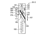
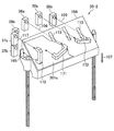
- a plurality of banknote sensors 38 may be arranged so as to form a plurality of optical paths according to the size of the banknote 301 to be detected.
- the reject cassette 35-2 is provided with two sets of banknote sensors 38, and four optical paths 109 are formed.
- each optical path 109 passing through the integration table 164 is also different.
- the banknote 301a blocks at least one of the optical paths 109 formed by the banknote sensor 38, The banknote 301a can be detected.
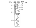
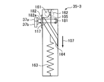
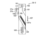
- FIG. 19 is a conceptual vertical sectional view showing the structure of a reject cassette 35-3 according to the third embodiment of the present invention.
- FIG. 21 is a simplified perspective view of the reject cassette 35-3 according to the present embodiment.
- the reject cassette 35-3 includes a prism 181 in addition to the drive roller 161, the idle roller 162, the stage spring 163, and the stacking table 164.
- the drive roller 161, the idle roller 162, the stage spring 163, and the stacking table 164 may be the same as those in the above-described embodiments.
- the prism 181 is configured to refract the light 117 emitted from the light emitting unit 37a of the integrated table sensor 37 and guide it to the light receiving unit 37b. However, the prism 181 does not interlock with the operation of the integrated table 164, for example, the cassette 35. -3 is fixedly provided on the housing.
- a shutter 182 is further provided between the reject cassette 35-3 and the stacking table sensor 37.
- the shutter 182 is generally formed of an optically opaque light blocking material that blocks the optical path 117, but an optical through hole 182a that allows the optical path 117 formed by the integrated stand sensor 37 to pass therethrough is opened. ing.
- the shutter 182 is arranged to engage with the stacking table 164 and move up and down in conjunction with the operation of the stacking table 164.
- the shutter 182 may be configured to move up and down along a sliding groove (not shown) or to rotate about a rotation axis. In any case, as illustrated in FIG. 21, the shutter 182 is pushed up by the stacking table 164 when the stacking table 164 is above a predetermined position. In this state, the optical path 117 formed by the integrated table sensor 37 passes through the hole 182a provided in the shutter 182 and the slit 113 provided in the integrated table 164.
- the optical path 117 that has passed through the hole 182 a provided in the shutter 182 is blocked by the banknote 301 when the banknote 301 is stacked on the stacking table 164.
- the stacking table sensor 37 in the present embodiment also includes a function as the banknote sensor 38.
- the shutter 182 is configured such that when the stacking table 164 descends due to its own weight, the shutter 182 also moves to a position where the light path 117 is blocked in conjunction with the stacking table 164 and stops there. Specifically, as shown in FIG. 21, a projection 183 is provided on the shutter 182. When the shutter 182 is lowered as the stacking table 164 is lowered, the projection 183 is engaged with the stopper 401. This prevents further lowering of the shutter 182.
- the 2 determines whether or not the bills 301 are stacked on the stacking table 164 inside the reject cassette 35-3 based on the detection result of the stacking table sensor 37 having the above-described configuration. Since the sensor 37 in the present embodiment is an optical sensor, when the light 117 emitted from the light emitting unit 37a is received by the light receiving unit 37b, the detection result indicates “bright”. When the light path 117 is blocked, the detection result indicates “dark”.
- the determination unit 20 determines that the banknote 301 is not stacked on the stacking table 164. This is the case where the stacking table sensor 37 detects that the stacking table 164 is above a predetermined position, or the stacking of banknotes 301 is not detected. It is determined that banknotes are not accumulated on the table 164.
- the determination unit 20 determines that the banknote 301 is stacked on the stacking table 164. This is a case where the stacking table sensor 37 detects that the stacking table 164 is lowered from a predetermined position, or a stack of banknotes 301 is detected. It is determined that banknotes are stacked on the stacking table 164.
- FIGS. 20A to 20C are conceptual vertical sectional views specifically illustrating the state transition when the bill 301 is stacked on the reject cassette 35-3.
- the stacking table 164 in the reject cassette 35-3 is pushed up to the initial position by the stage spring 163 as shown in FIG. Thereafter, when the banknote 301 is stacked on the stacking table 164, the optical path 117 formed by the stacking table sensor 37 is blocked by the banknote 301 as shown in FIG. At this time, since the stacking table sensor 37 presents “dark”, the determination unit 20 determines that banknotes are stacked on the stacking table 164.
- the determination unit 20 determines that the banknotes 301 are stacked on the stacking table 164.
- the stacking table 164 may be lowered further than in the normal case shown in FIG. 20B depending on the weight and thickness of the bill 301a such as a wet bill.
- the shutter 182 is further lowered in conjunction with the stacking table 164.
- the protrusion 183 provided on the shutter 182 engages with the stopper 401, and the optical path 117 formed by the stacking table sensor 37 is changed.
- the determination unit 20 determines that the bills 301a are stacked on the stacking table 164.
- the banknote weight becomes zero, so that the stacking table 164 is pushed up to the initial position by the stage spring 163 again.
- the optical path 117 formed by the integrated platform sensor 37 is not blocked.
- the determination unit 20 determines that the banknote 301 is not stacked on the stacking table 164.
- a shutter 182 that operates in conjunction with the stacking table 164 is provided, so that the presence or absence of the stacked banknote 301 can be more accurately determined by the single optical sensor 37. it can. Therefore, the number of sensors is reduced, and therefore the amount of connection lines and the size of the substrate can be reduced, so that the entire apparatus can be reduced in size and cost.
- the determination unit 20 determines that the stacking table 164 is above a predetermined position when the detection result by the stacking table sensor 37 is “dark”.
- the present invention is not limited to these specific embodiments.
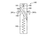
- the determination by the determination unit 20 may be performed when the stacking table 164 is predetermined when the detection result by the stacking table sensor 37 is “bright”. You may judge that it exists above a position. Therefore, as shown in FIG. 22 as the fourth embodiment, when the prism 191 is attached to the stacking table 164 and the detection result by the stacking table sensor 37 is “bright”, it is determined that the stacking table 164 is above the predetermined position. You may comprise.
- the reject cassette 35-4 includes a prism 191 in addition to the drive roller 161, the idle roller 162, the stage spring 163, and the stacking table 164.
- the driving roller 161, the idle roller 162, the stage spring 163, and the stacking table 164 may be the same as those in each embodiment.
- the prism 191 refracts the light 117 emitted from the light emitting unit 37a of the integrated platform sensor 37 and guides it to the light receiving unit 37b.
- the prism 191 is attached to the stacking table 164 so as to interlock with the operation of the stacking table 164, and guides the light 117 emitted from the light emitting unit 37a to the light receiving unit 37b when the stacking table 164 is above a predetermined position. Fixed in position.
- the sensor 37 according to the fourth embodiment is an optical sensor, when the light 117 emitted from the light emitting unit 37a is received by the light receiving unit 37b, the detection result is “bright” and the light cannot be received. Presents “dark”. Therefore, in the reject cassette 35-4 according to the fourth embodiment, when the stacking table 164 is above a predetermined position, the light 117 from the light emitting unit 37a is guided to the light receiving unit 37b by the prism 191, and the stacking table The detection result by the sensor 37 is “bright”. Therefore, the determination unit 20 determines that the stacking table 164 is above the predetermined position when the detection result by the stacking table sensor 37 is “bright”.
- optical sensors are used as the stacking table sensor 37 and the bill sensor 38, but the present invention is not limited to such an example.
- a detector based on another operation principle such as a contact sensor or a magnetic sensor can be used as the integrated table sensor 37 and the bill sensor 38.
- each embodiment is mainly configured to provide one set of banknote sensors 38, the present invention is not limited to such an example.
- position a required number of banknote sensors such as 2 sets or 3 sets, according to the magnitude
- the senor is provided outside the reject cassette, but each sensor may be provided inside the reject cassette.
- the stacking table 164 has an inclined surface, and banknotes are stacked in an inclined posture on the inclined surface.
- the present invention is not limited to such an example.
- the stacking surface may be formed horizontally and banknotes may be stacked vertically in a horizontal posture. Even in this case, it is possible to determine whether or not banknotes are stacked on the stacking table by detecting the lowering of the stacking table.
Landscapes
- Engineering & Computer Science (AREA)
- Mechanical Engineering (AREA)
- Physics & Mathematics (AREA)
- General Physics & Mathematics (AREA)
- Pile Receivers (AREA)
- Automatic Disk Changers (AREA)
- Inspection Of Paper Currency And Valuable Securities (AREA)
Priority Applications (4)
| Application Number | Priority Date | Filing Date | Title |
|---|---|---|---|
| BR112012033696-7A BR112012033696B1 (pt) | 2010-08-26 | 2011-05-31 | dispositivo de acúmulo de meio |
| RU2012156273/08A RU2532711C2 (ru) | 2010-08-26 | 2011-05-31 | Устройство накапливания носителей |
| US13/807,911 US8973916B2 (en) | 2010-08-26 | 2011-05-31 | Medium accumulating device with accumulation table detector |
| CN201180032546.XA CN102971244B (zh) | 2010-08-26 | 2011-05-31 | 媒体蓄积装置 |
Applications Claiming Priority (2)
| Application Number | Priority Date | Filing Date | Title |
|---|---|---|---|
| JP2010189233A JP5440445B2 (ja) | 2010-08-26 | 2010-08-26 | 媒体集積装置 |
| JP2010-189233 | 2010-08-26 |
Publications (1)
| Publication Number | Publication Date |
|---|---|
| WO2012026178A1 true WO2012026178A1 (ja) | 2012-03-01 |
Family
ID=45723194
Family Applications (1)
| Application Number | Title | Priority Date | Filing Date |
|---|---|---|---|
| PCT/JP2011/062503 Ceased WO2012026178A1 (ja) | 2010-08-26 | 2011-05-31 | 媒体集積装置 |
Country Status (6)
| Country | Link |
|---|---|
| US (1) | US8973916B2 (https=) |
| JP (1) | JP5440445B2 (https=) |
| CN (3) | CN103778725B (https=) |
| BR (1) | BR112012033696B1 (https=) |
| RU (2) | RU2532711C2 (https=) |
| WO (1) | WO2012026178A1 (https=) |
Families Citing this family (16)
| Publication number | Priority date | Publication date | Assignee | Title |
|---|---|---|---|---|
| JP6255695B2 (ja) | 2012-10-05 | 2018-01-10 | 株式会社リコー | 非水系光重合性組成物、インクジェットインク、及びインクカートリッジ |
| JP6102487B2 (ja) * | 2013-05-10 | 2017-03-29 | 沖電気工業株式会社 | 媒体収納装置及び媒体取引装置 |
| JP6060806B2 (ja) * | 2013-05-10 | 2017-01-18 | 沖電気工業株式会社 | 媒体収納装置及び媒体取引装置 |
| CN104123785A (zh) * | 2014-07-18 | 2014-10-29 | 广州广电运通金融电子股份有限公司 | 一种片状介质收纳装置 |
| JP6439371B2 (ja) * | 2014-10-17 | 2018-12-19 | 沖電気工業株式会社 | 媒体収容装置及び媒体取引装置 |
| CN104537760B (zh) * | 2014-12-19 | 2018-03-02 | 深圳怡化电脑股份有限公司 | 钞箱、自动柜员机及钞票状态监测方法 |
| JP6459619B2 (ja) * | 2015-02-24 | 2019-01-30 | 沖電気工業株式会社 | 媒体収納庫及び媒体処理装置 |
| CN105006060B (zh) * | 2015-07-28 | 2019-10-11 | 深圳怡化电脑股份有限公司 | 钞箱、自动柜员机及钞箱状态监测方法 |
| US9875593B1 (en) * | 2015-08-07 | 2018-01-23 | Cummins-Allison Corp. | Systems, methods and devices for coin processing and coin recycling |
| JP6751535B2 (ja) * | 2015-10-19 | 2020-09-09 | 日東電工株式会社 | 平板ワーク切断回収システム、および平板ワーク切断回収方法 |
| US11412900B2 (en) | 2016-04-11 | 2022-08-16 | Gpcp Ip Holdings Llc | Sheet product dispenser with motor operation sensing |
| US11395566B2 (en) | 2016-04-11 | 2022-07-26 | Gpcp Ip Holdings Llc | Sheet product dispenser |
| CN108328408B (zh) * | 2018-03-07 | 2024-04-19 | 中邮科技股份有限公司 | 一种邮件摞里单封邮件向上折边的检测装置及方法 |
| CN109399260B (zh) * | 2018-10-23 | 2020-11-03 | 山东叶华纸制品包装有限公司 | 一种纸箱印刷工序用物料供给方法 |
| JP7405583B2 (ja) * | 2019-12-03 | 2023-12-26 | シャープ株式会社 | 紙幣収納装置 |
| JP7321663B2 (ja) * | 2020-08-05 | 2023-08-07 | 富士通フロンテック株式会社 | 紙葉類収納装置、及び、紙葉類取扱装置 |
Citations (4)
| Publication number | Priority date | Publication date | Assignee | Title |
|---|---|---|---|---|
| JPH03105160U (https=) * | 1990-02-16 | 1991-10-31 | ||
| JP2001335236A (ja) * | 2000-05-25 | 2001-12-04 | Canon Inc | シート処理装置及びこれを備えた画像形成装置 |
| JP2005015123A (ja) * | 2003-06-25 | 2005-01-20 | Canon Inc | シート搬送装置 |
| JP2009102096A (ja) * | 2007-10-22 | 2009-05-14 | Ricoh Elemex Corp | 用紙後処理装置 |
Family Cites Families (20)
| Publication number | Priority date | Publication date | Assignee | Title |
|---|---|---|---|---|
| JP2641275B2 (ja) | 1988-11-28 | 1997-08-13 | 株式会社日立製作所 | 紙葉類堆積・繰り出し装置 |
| JPH02225238A (ja) * | 1989-02-23 | 1990-09-07 | Hitachi Ltd | 紙葉類取扱装置における紙葉類堆積量検出方法 |
| JPH03105160A (ja) * | 1989-09-18 | 1991-05-01 | Hitachi Ltd | スクリュー冷凍機 |
| JP3420787B2 (ja) | 1992-08-03 | 2003-06-30 | 沖電気工業株式会社 | 搬送媒体の検出装置 |
| JP3218812B2 (ja) * | 1993-06-22 | 2001-10-15 | オムロン株式会社 | 紙葉類収納量検知装置 |
| US6145826A (en) * | 1997-10-27 | 2000-11-14 | Canon Kabushiki Kaisha | Image forming apparatus |
| JP3620967B2 (ja) | 1998-06-30 | 2005-02-16 | 沖電気工業株式会社 | 紙幣収納箱 |
| RU2175210C2 (ru) | 1999-11-02 | 2001-10-27 | Российский Федеральный Ядерный Центр - Всероссийский Научно-Исследовательский Институт Экспериментальной Физики | Устройство для хранения предметов |
| JP4160362B2 (ja) | 2002-10-30 | 2008-10-01 | グローリー株式会社 | 集積装置および循環式紙幣入出金機 |
| FI5905U1 (fi) * | 2003-05-12 | 2003-08-15 | Metso Minerals Tampere Oy | Mineraalimateriaalien prosessointilaitos |
| US6848688B1 (en) | 2003-09-08 | 2005-02-01 | Xerox Corporation | Automatically elevating sheet tamper and sheet input level for compiling large printed sets |
| JP4238193B2 (ja) | 2004-05-18 | 2009-03-11 | 株式会社リコー | 用紙折り装置及び画像形成装置 |
| JP4446806B2 (ja) * | 2004-06-16 | 2010-04-07 | 日立オムロンターミナルソリューションズ株式会社 | 紙幣処理装置 |
| CN100562472C (zh) | 2004-09-16 | 2009-11-25 | 株式会社理光 | 页处理装置以及成像装置 |
| WO2007017923A1 (ja) | 2005-08-05 | 2007-02-15 | Glory Ltd. | 紙葉類収納繰出装置 |
| RU2366789C1 (ru) | 2006-05-29 | 2009-09-10 | Федеральное государственное унитарное предприятие "Российский федеральный ядерный центр-Всероссийский научно-исследовательский институт технической физики имени академика Е.И. Забабахина" | Устройство для хранения и выдачи предметов |
| US7690637B2 (en) * | 2007-02-01 | 2010-04-06 | Toshiba Tec Kabushiki Kaisha | Sheet processing apparatus and sheet processing method |
| JP5045164B2 (ja) | 2007-03-13 | 2012-10-10 | 沖電気工業株式会社 | 紙幣自動入出金機 |
| JP5120226B2 (ja) | 2008-11-20 | 2013-01-16 | 沖電気工業株式会社 | 媒体取扱装置 |
| JP5267072B2 (ja) | 2008-11-25 | 2013-08-21 | 沖電気工業株式会社 | 紙幣集積機構 |
-
2010
- 2010-08-26 JP JP2010189233A patent/JP5440445B2/ja active Active
-
2011
- 2011-05-31 WO PCT/JP2011/062503 patent/WO2012026178A1/ja not_active Ceased
- 2011-05-31 CN CN201410012383.4A patent/CN103778725B/zh active Active
- 2011-05-31 RU RU2012156273/08A patent/RU2532711C2/ru active
- 2011-05-31 CN CN201510017553.2A patent/CN104658098B/zh active Active
- 2011-05-31 BR BR112012033696-7A patent/BR112012033696B1/pt active IP Right Grant
- 2011-05-31 US US13/807,911 patent/US8973916B2/en active Active
- 2011-05-31 CN CN201180032546.XA patent/CN102971244B/zh active Active
-
2014
- 2014-08-12 RU RU2014133185/08A patent/RU2584962C2/ru active
Patent Citations (4)
| Publication number | Priority date | Publication date | Assignee | Title |
|---|---|---|---|---|
| JPH03105160U (https=) * | 1990-02-16 | 1991-10-31 | ||
| JP2001335236A (ja) * | 2000-05-25 | 2001-12-04 | Canon Inc | シート処理装置及びこれを備えた画像形成装置 |
| JP2005015123A (ja) * | 2003-06-25 | 2005-01-20 | Canon Inc | シート搬送装置 |
| JP2009102096A (ja) * | 2007-10-22 | 2009-05-14 | Ricoh Elemex Corp | 用紙後処理装置 |
Also Published As
| Publication number | Publication date |
|---|---|
| JP2012046301A (ja) | 2012-03-08 |
| CN102971244B (zh) | 2016-01-27 |
| RU2012156273A (ru) | 2014-06-27 |
| CN103778725A (zh) | 2014-05-07 |
| RU2532711C2 (ru) | 2014-11-10 |
| CN104658098B (zh) | 2018-02-02 |
| US20130099442A1 (en) | 2013-04-25 |
| CN102971244A (zh) | 2013-03-13 |
| RU2584962C2 (ru) | 2016-05-20 |
| BR112012033696B1 (pt) | 2020-12-01 |
| RU2014133185A (ru) | 2016-03-10 |
| US8973916B2 (en) | 2015-03-10 |
| CN104658098A (zh) | 2015-05-27 |
| CN103778725B (zh) | 2016-10-12 |
| JP5440445B2 (ja) | 2014-03-12 |
| BR112012033696A2 (pt) | 2016-12-06 |
Similar Documents
| Publication | Publication Date | Title |
|---|---|---|
| JP5440445B2 (ja) | 媒体集積装置 | |
| JP5564915B2 (ja) | 紙幣入出金機 | |
| KR100984533B1 (ko) | 지엽류 집적 장치 | |
| JP4877124B2 (ja) | 紙葉類処理装置 | |
| CN104952149B (zh) | 纸币累积装置 | |
| CN106251473B (zh) | 金融设备及媒介物堆积装置 | |
| CN102385770A (zh) | 纸张类处理装置 | |
| JP5859945B2 (ja) | 紙幣取扱装置および紙幣検出方法 | |
| KR101866992B1 (ko) | 카세트 밀판 잠금장치 | |
| JP6398592B2 (ja) | 媒体収納装置及び媒体取引装置 | |
| JPH0944723A (ja) | 自動取引装置 | |
| JP2778952B2 (ja) | 自動取引装置 | |
| KR100722876B1 (ko) | 금융자동화기기의 출금장치의 현금회수방법 | |
| WO2016201268A1 (en) | An automated transaction machine with shuttle | |
| KR101587689B1 (ko) | 금융기기 | |
| JP5258681B2 (ja) | 紙幣処理装置 | |
| KR101932189B1 (ko) | 매체 입금장치 및 금융기기 | |
| KR101799200B1 (ko) | 매체 가이드장치와 매체 보관장치 및 금융기기 | |
| KR20180010752A (ko) | 금융 기기 | |
| JPH08329312A (ja) | 自動取引装置 |
Legal Events
| Date | Code | Title | Description |
|---|---|---|---|
| WWE | Wipo information: entry into national phase |
Ref document number: 201180032546.X Country of ref document: CN |
|
| 121 | Ep: the epo has been informed by wipo that ep was designated in this application |
Ref document number: 11819651 Country of ref document: EP Kind code of ref document: A1 |
|
| WWE | Wipo information: entry into national phase |
Ref document number: 10555/CHENP/2012 Country of ref document: IN |
|
| WWE | Wipo information: entry into national phase |
Ref document number: 2012156273 Country of ref document: RU |
|
| WWE | Wipo information: entry into national phase |
Ref document number: 13807911 Country of ref document: US |
|
| NENP | Non-entry into the national phase |
Ref country code: DE |
|
| 122 | Ep: pct application non-entry in european phase |
Ref document number: 11819651 Country of ref document: EP Kind code of ref document: A1 |
|
| REG | Reference to national code |
Ref country code: BR Ref legal event code: B01A Ref document number: 112012033696 Country of ref document: BR |
|
| ENP | Entry into the national phase |
Ref document number: 112012033696 Country of ref document: BR Kind code of ref document: A2 Effective date: 20121228 |