WO2012020652A1 - 誘導加熱装置および誘導加熱方法 - Google Patents
誘導加熱装置および誘導加熱方法 Download PDFInfo
- Publication number
- WO2012020652A1 WO2012020652A1 PCT/JP2011/067346 JP2011067346W WO2012020652A1 WO 2012020652 A1 WO2012020652 A1 WO 2012020652A1 JP 2011067346 W JP2011067346 W JP 2011067346W WO 2012020652 A1 WO2012020652 A1 WO 2012020652A1
- Authority
- WO
- WIPO (PCT)
- Prior art keywords
- induction heating
- heating coil
- coils
- induction
- coil
- Prior art date
- Legal status (The legal status is an assumption and is not a legal conclusion. Google has not performed a legal analysis and makes no representation as to the accuracy of the status listed.)
- Ceased
Links
Images



Classifications
-
- H—ELECTRICITY
- H05—ELECTRIC TECHNIQUES NOT OTHERWISE PROVIDED FOR
- H05B—ELECTRIC HEATING; ELECTRIC LIGHT SOURCES NOT OTHERWISE PROVIDED FOR; CIRCUIT ARRANGEMENTS FOR ELECTRIC LIGHT SOURCES, IN GENERAL
- H05B6/00—Heating by electric, magnetic or electromagnetic fields
- H05B6/02—Induction heating
- H05B6/06—Control, e.g. of temperature, of power
-
- H—ELECTRICITY
- H05—ELECTRIC TECHNIQUES NOT OTHERWISE PROVIDED FOR
- H05B—ELECTRIC HEATING; ELECTRIC LIGHT SOURCES NOT OTHERWISE PROVIDED FOR; CIRCUIT ARRANGEMENTS FOR ELECTRIC LIGHT SOURCES, IN GENERAL
- H05B6/00—Heating by electric, magnetic or electromagnetic fields
- H05B6/02—Induction heating
- H05B6/10—Induction heating apparatus, other than furnaces, for specific applications
- H05B6/105—Induction heating apparatus, other than furnaces, for specific applications using a susceptor
-
- H—ELECTRICITY
- H05—ELECTRIC TECHNIQUES NOT OTHERWISE PROVIDED FOR
- H05B—ELECTRIC HEATING; ELECTRIC LIGHT SOURCES NOT OTHERWISE PROVIDED FOR; CIRCUIT ARRANGEMENTS FOR ELECTRIC LIGHT SOURCES, IN GENERAL
- H05B6/00—Heating by electric, magnetic or electromagnetic fields
- H05B6/02—Induction heating
- H05B6/36—Coil arrangements
- H05B6/44—Coil arrangements having more than one coil or coil segment
-
- H—ELECTRICITY
- H10—SEMICONDUCTOR DEVICES; ELECTRIC SOLID-STATE DEVICES NOT OTHERWISE PROVIDED FOR
- H10P—GENERIC PROCESSES OR APPARATUS FOR THE MANUFACTURE OR TREATMENT OF DEVICES COVERED BY CLASS H10
- H10P72/00—Handling or holding of wafers, substrates or devices during manufacture or treatment thereof
- H10P72/04—Apparatus for manufacture or treatment
- H10P72/0431—Apparatus for thermal treatment
- H10P72/0434—Apparatus for thermal treatment mainly by convection
-
- H—ELECTRICITY
- H10—SEMICONDUCTOR DEVICES; ELECTRIC SOLID-STATE DEVICES NOT OTHERWISE PROVIDED FOR
- H10P—GENERIC PROCESSES OR APPARATUS FOR THE MANUFACTURE OR TREATMENT OF DEVICES COVERED BY CLASS H10
- H10P95/00—Generic processes or apparatus for manufacture or treatments not covered by the other groups of this subclass
- H10P95/90—Thermal treatments, e.g. annealing or sintering
Definitions
- the present invention relates to an induction heating apparatus and method, and more particularly to an apparatus and method for heat treatment of a semiconductor substrate suitable for controlling the temperature of an object to be heated when a substrate such as a large-diameter wafer is processed.
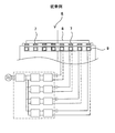
- the heat treatment apparatus disclosed in Patent Document 1 is a batch-type heat treatment apparatus, in which wafers 2 stacked in multiple stages are placed in a quartz process tube 3, and graphite or the like is placed on the outer periphery of the process tube 3.
- the heating tower 4 formed of the conductive member is disposed, and the solenoid-like induction heating coil 5 is disposed on the outer periphery thereof.
- the heating tower 4 is heated by the influence of the magnetic flux generated by the induction heating coil 5, and the wafer 2 disposed in the process tube 3 is heated by the radiant heat from the heating tower 4.
- the heat treatment apparatus disclosed in Patent Document 2 is a single-wafer type heat treatment apparatus, in which a susceptor 7 divided into concentric circles is formed of graphite or the like, and the upper surface of the susceptor 7 is formed.
- a wafer 8 is placed on the side, and a plurality of annular induction heating coils 9 are arranged concentrically on the lower surface side to enable individual power control for the plurality of induction heating coils 9.
- the heat treatment apparatus 6 having such a configuration heat transfer between the susceptor 7 positioned in the heating range of each induction heating coil 9 and the susceptor 7 heated by the other induction heating coil 9 is suppressed. Further, the temperature distribution controllability of the wafer 8 by power control on the induction heating coil 9 is improved.
- Patent Document 2 it is described that the distribution of heat generation is favorably controlled by dividing the susceptor 7 on which the wafer 8 is placed.
- Patent Document 3 the cross-sectional shape of the susceptor is devised. It is disclosed to improve the heat generation distribution.
- the heat treatment apparatus disclosed in Patent Document 3 pays attention to the fact that the heat generation amount is reduced on the inner side where the diameter of the induction heating coil formed in an annular shape is small, and by increasing the thickness of the inner part of the susceptor, The inner part is closer to the induction heating coil than the part, and the amount of heat generation and the heat capacity are increased.
- the magnetic flux acts perpendicularly to the graphite. For this reason, when a metal film or the like is formed on the surface of the wafer as an object to be heated, the wafer may be directly heated, and temperature distribution control may be disturbed.
- An object of the present invention is to provide an induction heating apparatus and method capable of enabling good heating control.
- an induction heating apparatus is arranged on the outer peripheral side of a susceptor that is horizontally arranged and arranged in a plurality of layers in the vertical direction, A plurality of induction heating coils having a central axis parallel to each other and stacked adjacently along the arrangement direction of the susceptor; and an inverter that inputs current so that the adjacent induction heating coils are depolarized from each other And zone control means for individually controlling the ratio of power supplied to the plurality of induction heating coils arranged adjacent to each other.
- the induction heating coil includes at least one main heating coil and a subordinate heating coil that is electromagnetically coupled to the main heating coil. It is preferable to connect a reverse coupling coil that generates a mutual inductance having a polarity opposite to the mutual inductance generated between the subordinate heating coils.
- the mutual induction electromotive force generated between the main heating coil and the subordinate heating coil can be canceled or partially canceled by the action of the reverse coupling coil.
- the induction heating device has a core around which the main heating coil and the subordinate heating coil are wound, and the reverse coupling coil is connected to the subordinate heating coil wound around the core.
- the induction heating device may be arranged so as to have an additive relationship.
- the reverse coupling coil is placed between the subordinate heating coil and the main heating coil by matching the frequency of the current applied to the main heating coil and the subordinate heating coil and synchronizing the current waveform.
- a mutual inductance having a reverse polarity is generated with respect to the generated mutual inductance. Therefore, it is possible to cancel or partially cancel the mutual induction electromotive force generated between the main heating coil and the subordinate heating coil.
- An induction heating method for achieving the above object is a method of induction heating an object to be heated arranged on a susceptor that is horizontally arranged and arranged in a plurality of layers in the vertical direction, the object to be heated in the susceptor.
- a plurality of induction heating coils that generate a magnetic flux that is horizontal with respect to the mounting surface are stacked adjacently in the stacking direction of the susceptor, and the adjacent induction heating coils are depolarized with respect to each other.
- the ratio of electric power supplied to the induction heating coil is individually controlled.
- a mutual inductance having a polarity opposite to that of the mutual inductance generated between the adjacent induction heating coils is generated, and the mutual inductance generated between the induction heating coils is offset or partially. It is desirable to cancel. By adopting such a method, it is possible to cancel or partially cancel the mutual induction electromotive force generated between the main heating coil and the subordinate heating coil.
- the mutual inductance having the reverse polarity is generated by a reverse coupling coil formed around the same core as the core around which the induction heating coil is wound. It is desirable. By adopting such a method, the reverse coupling coil can be arranged in a compact manner.
- induction heating apparatus and method having the above-described features, even when a plurality of induction heating coils are arranged in the vertical direction while applying a horizontal magnetic flux to the susceptor, mutual induction between the induction heating coils is achieved. The influence can be suppressed, and good heating control is possible.
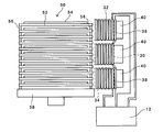
- FIG. 1-1 is a block diagram illustrating a planar configuration of the heat treatment apparatus
- FIG. 1-2 is a block diagram illustrating a side configuration of the heat treatment apparatus
- FIG. 2 is a diagram for explaining the configuration of the power supply unit.
- the heat treatment apparatus 10 is of a batch type in which heat treatment is performed by stacking a wafer 54 as an object to be heated and a susceptor 52 as a heating element in multiple stages.
- the heat treatment apparatus 10 includes a boat 50 in which wafers 54 and horizontally arranged susceptors 52 are stacked in multiple stages in the vertical direction, and an induction heating coil that heats the susceptor 52 (a main heating coil 30 and a subordinate heating coil 32, which will be described in detail later). 34, the reverse coupling coils 36, 38), and the power supply unit 12 that supplies power to the induction heating coil.
- the susceptor 52 may be made of a conductive member, for example, graphite, SiC, SiC-coated graphite, refractory metal, or the like.
- the susceptor 52 in the present embodiment has a circular planar shape.
- the susceptors 52 constituting the boat 50 are stacked and arranged via support members 56, respectively.
- the support member 56 is preferably made of quartz or the like that is not affected by heating by electromagnetic induction.
- the boat 50 in this embodiment is mounted on a rotary table 58 having a motor (not shown), and can rotate the susceptor 52 and the wafer 54 during the heat treatment process.
- a motor not shown
- the induction heating coil according to the embodiment includes one main heating coil 30 and two subordinate heating coils 32 and 34 arranged adjacent to each other so as to be electromagnetically coupled to the main heating coil 30. It is arrange
- the main heating coil 30 and the subordinate heating coils 32 and 34 are stacked adjacent to each other in the same direction as the stacking direction of the susceptor 52.
- the main heating coil 30 according to the embodiment includes reverse coupling coils 36 and 38 that electromagnetically reversely couple the two subordinate heating coils 32 and 34.
- the electromagnetic coupling causes, for example, an induced electromotive force in a direction to cancel the magnetic flux generated by the main heating coil 30 to the subordinate heating coils 32 and 34 based on a change in current supplied to the main heating coil 30.
- a state that is in a mutual induction relationship that is, a state that causes mutual inductance.
- Electromagnetic reverse coupling refers to the main heating coil 30 when the main heating coil 30 is viewed as a primary winding (primary coil) and the subordinate heating coils 32 and 34 are viewed as secondary windings (secondary coils).
- the sub-heating coils 32 and 34 are coupled to each other to generate a mutual inductance having a polarity opposite to that of the mutual inductance.
- Each induction heating coil (the main heating coil 30 and the subordinate heating coils 32 and 34) is configured by winding a copper wire around a core 40 disposed on the outer peripheral side of the boat 50.
- the core 40 may be made of a ferrite ceramic or the like, and may be formed by firing after forming a clay-like raw material. This is because if the core 40 is formed of such a member, the shape can be freely formed. Further, by using the core 40, the diffusion of magnetic flux can be prevented compared to the case of the induction heating coil alone, and highly efficient induction heating with concentrated magnetic flux can be realized.
- the winding directions of the main heating coil 30 and the subordinate heating coils 32 and 34 around the core 40 are the same.
- the reverse coupling coils 36 and 38 have the winding direction opposite to that of the subordinate heating coils 32 and 34 on the rear end side of the core 40 where the subordinate heating coils 32 and 34 are arranged on the front end side (susceptor 52 arrangement side). Arranged in a state.
- the mutual inductance generated between the main heating coil 30 and the subordinate heating coils 32, 34 by matching the directions of the currents supplied to the main heating coil 30 and the subordinate heating coils 32, 34.
- the winding ratio between the subordinate heating coils 32 and 34 and the reverse coupling coils 36 and 38 is preferably about 7: 1.
- the number of turns of the main heating coil 30 is preferably matched with the number of turns of the subordinate heating coils 32 and 34.
- the current input to the subordinate heating coil 32 is I 1
- the current voltage is V 1
- the current input to the main heating coil 30 is I 2
- the current voltage is V 2.
- the mutual inductance ⁇ M 12 ( ⁇ M 21 ) generated between the coil 32 and the main heating coil 30 is equal
- the mutual inductance + M 23 (+ M 32 ) generated between the reverse coupling coil 38 and the subordinate heating coil 34 When the mutual inductance ⁇ M 23 (+ M 32 ) generated between the subordinate heating coil 34 and the main heating coil 30 is equal, Expressions 1 to 3 are established.
- L 1 is the self-inductance of the subordinate heating coil 32
- L 2 is the self-inductance of the main heating coil 30
- L 3 is the self-inductance of the subordinate heating coil 34.
- L1 and L2 are self-inductances in the primary and secondary windings). Note that the self-inductance L can be obtained by Equation 5.
- N is the number of turns of the coil
- ⁇ is the magnetic flux (wb)
- I is the current value.
- the number of turns of the coil differs between the main heating coil 30 and the reverse coupling coils 36 and 38.
- the magnetic flux (d ⁇ ) per unit current (dI) is equal, the value of the self-inductance L will be different. Therefore, in order to make the mutual inductance M generated between the reverse coupling coils 36 and 38 and the subordinate heating coils 32 and 34 the same (the polarities are opposite), it is necessary to adjust the coupling coefficient k.
- the coupling coefficient k can be changed according to the distance between the coils and the arrangement form.
- a coupling coefficient k for obtaining a mutual inductance + M having a reverse polarity is calculated.
- the reverse coupling coils 36 and 38 are arranged after adjusting the arrangement form and the distance between the coils.
- the term including the mutual inductance due to mutual induction between the main heating coil 30 and the subordinate heating coils 32 and 34 is canceled, and mutual induction between the adjacent induction heating coils is cancelled.
- the influence of induction can be avoided.
- the core 40 around which the main heating coil 30 and the subordinate heating coils 32 and 34 are wound has a central axis parallel to the mounting surface of the wafer 54 in the susceptor 52 (the central axis of the wafer 54 and the central axis of the core 40 in the mounting state). Are arranged in such a way as to be perpendicular to each other.
- the leading end surface of the core 40 serving as the magnetic pole surface is opposed to the susceptor 52. With such a configuration, an alternating magnetic flux is generated in a direction parallel to the wafer 54 mounting surface of the susceptor 52 from the magnetic pole surface around which the main heating coil 30 and the subordinate heating coils 32 and 34 are wound.
- the main heating coil 30 is regarded as a primary winding and the subordinate heating coils 32 and 34 are regarded as secondary windings, the details will be described later so that the directions of the currents applied to both are the same. Inverters 14a to 14c are connected. For this reason, the main heating coil 30 and the subordinate heating coils 32 and 34 stacked in the vertical direction are depolarized from each other.
- the main heating coil 30 and the subordinate heating coils 32, 34 having such an arrangement relationship have the direction of the magnetic flux radiated so as to intersect perpendicularly to the mounting surface of the susceptor 52. , They are reversed and cancel each other. Therefore, even when a metal film or the like is formed on the surface of the wafer 54 placed on the susceptor 52, there is no possibility that the wafer 54 is directly heated by the influence of the magnetic flux in the vertical direction, and the temperature of the wafer 54 is increased. There is no risk of variations in distribution.
- the main heating coil 30, the subordinate heating coils 32 and 34, and the reverse coupling coils 36 and 38 are preferably tubular members (for example, copper pipes) having a hollow inside.
- a cooling member for example, cooling water
- the main heating coil 30 and the subordinate heating coils 32 and 34 are arranged adjacent to each other in the vertical direction along the boat 50 in which the susceptors 52 on which the wafers 54 are stacked are stacked in the vertical direction. .
- the susceptors 52 on which the wafers 54 are stacked are stacked in the vertical direction.
- power control is performed individually on the stacked induction heating coils, the temperature distribution in the vertical direction in the plurality of susceptors 52 stacked in the boat 50 can be controlled. It is also possible to suppress temperature variations.
- the main heating coil 30 and the subordinate heating coils 32 and 34 configured as described above are connected to a single power supply unit 12.
- the power supply unit 12 is provided with inverters 14a to 14c, choppers 16a to 16c, a converter 18, a three-phase AC power supply 20, and zone control means 22, and each induction heating coil (main heating coil 30 and subordinate heating coil 32). , 34) can be adjusted so that the current, voltage, frequency, and the like to be supplied can be adjusted.
- inverters 14a to 14c employ series resonance type inverters. Therefore, as a configuration for easily switching the frequency, it is preferable to connect the resonance capacitor 26 in parallel and increase or decrease the capacitance by the switch 28 in accordance with the resonance frequency.
- the transformer 24 is disposed between each induction heating coil (the main heating coil 30 and the subordinate heating coil 32) and each inverter 14a to 14c.
- the zone control means 22 performs power control on the main heating coil 30 and each of the subordinate heating coils 32 and 34 while avoiding the influence of mutual induction generated between the adjacent main heating coil 30 and the subordinate heating coils 32 and 34. Take a role.
- the zone control means 22 matches the frequency of the current applied to the adjacent main heating coil 30 and the subordinate heating coils 32 and 34 based on the detected current frequency and waveform (current waveform), and
- the main heating coil 30 and the subordinate heating coils 32 and 34 arranged adjacent to each other are controlled by synchronizing the phase of the current waveform (the phase difference is 0 or the phase difference is approximated to 0), or by controlling to maintain a predetermined phase difference. It enables power control (zone control control) that avoids the influence of mutual induction between them.
- Such control includes, for example, detecting the current value, the frequency of the current, the voltage value, and the like applied to each induction heating coil (the main heating coil 30 and the subordinate heating coils 32 and 34), and this is detected by the zone control means 22.
- the zone control means 22 detects the phase between the current waveform input to the main heating coil 30 and the current waveform input to the subordinate heating coils 32 and 34, and synchronizes them or maintains a predetermined phase difference.
- the inverter 14b or the inverter 14c is configured to output a signal that instantaneously changes the frequency of the current applied to the subordinate heating coil 32 or the subordinate heating coil 34.
- a signal to be changed in units of elapsed time from the start of the heat treatment based on a control map (vertical temperature distribution control map) stored in a storage means (memory) (not shown) provided in the power supply unit 12.
- Power control for obtaining a desired vertical temperature distribution may be performed based on the temperature of the susceptor 52 that is output to the inverters 14a to 14c and the choppers 16a to 16c and fed back from temperature measurement means (not shown). .
- the control map corrects the temperature change between the stacked susceptors 52 from the start of the heat treatment to the end of the heat treatment, and obtains an arbitrary temperature distribution (for example, a uniform temperature distribution). What is necessary is just to have recorded the electric power value given to the heating coils 32 and 34 with the elapsed time from the heat processing start.
- the power supply unit 12 instantaneously adjusts the frequency of the current to be applied to the subordinate heating coils 32 and 34 based on the signal from the zone control means 22 and performs phase control of the current waveform, and each induction.
- the temperature distribution in the vertical direction in the boat 50 can be controlled.
- the main heating coil 30 and the subordinate heating coils 32 and 34 are arranged.
- the influence of mutual induction in can be suppressed in advance. For this reason, the influence of mutual induction avoided by the zone control means 22 is reduced, and the controllability of power control for the main heating coil 30 and the subordinate heating coils 32 and 34 can be improved.
- the heat treatment apparatus 10 configured as described above, even when a conductive member such as a metal film is formed on the surface of the wafer 54, the metal film generates heat, and the temperature distribution of the wafer 54. There is no danger of being disturbed.
- FIG. 4A is a block diagram illustrating a planar configuration of the heat treatment apparatus 110 according to the second embodiment
- FIG. 4B is a block diagram illustrating a planar configuration of a core used in the heat treatment apparatus 110 according to the present embodiment.
- FIG. 4A is a block diagram illustrating a planar configuration of the heat treatment apparatus 110 according to the second embodiment
- FIG. 4B is a block diagram illustrating a planar configuration of a core used in the heat treatment apparatus 110 according to the present embodiment.
- the description of a power supply part is abbreviate
- the heat treatment apparatus 110 is characterized in that a plurality of induction heating coils corresponding to the subordinate heating coil 32, the main heating coil 30, and the subordinate heating coil 34 according to the first embodiment are provided. (In FIG. 4A, only the subordinate heating coils 132a and 132b are displayed. Hereinafter, in order to simplify the description, they are simply referred to as induction heating coils 132a and 132b).
- the horizontal heatable range is increased, and the temperature distribution in the surface of the wafer 154 can be stabilized. Become.
- a single core 140 around which a plurality of (two in the form shown in FIG. 4A) induction heating coils 132a and 132b is wound is used as a single magnetic pole 141a protruding from the yoke 141. 141b, induction heating coils 132a and 132b are wound respectively.
- the induction heating coils 132a and 132b arranged in the circumferential direction (horizontal direction) of the susceptor 152 are connected in parallel to the power supply unit (actually an inverter in the power supply unit). It is configured to do. This is because it is not necessary to consider the influence of mutual induction between the induction heating coil 132a and the induction heating coil 132b arranged in parallel by adopting such a configuration.
- each induction heating coil 132a, 132b is configured such that the magnetic flux generated by both the winding directions of the core 140 with respect to the magnetic poles 141a, 141b becomes a positive polarity.
- the generated magnetic flux is generated along a locus as indicated by broken lines a to c, and the center side of the susceptor 152 can be heated more than the magnetic flux generated by one induction heating coil.
- the two induction heating coils 132a and 132b may be selectable for single operation and mutual operation by a changeover switch (not shown). In such a configuration, since the heating range of the susceptor 152 changes depending on the combination of the induction heating coils to be operated, it becomes possible to control the temperature distribution in the wafer 154 plane.
Landscapes
- Physics & Mathematics (AREA)
- Electromagnetism (AREA)
- General Induction Heating (AREA)
Abstract
Description
このような方法を採ることにより、主加熱コイルと従属加熱コイルとの間に生ずる相互誘導起電力を相殺または一部相殺することができる。
このような方法を採ることにより、逆結合コイルをコンパクトに配置することができる。
熱処理装置10は、ウエハ54と水平配置されたサセプタ52を垂直方向に多段に積層配置したボート50と、サセプタ52を加熱する誘導加熱コイル(詳細を後述する主加熱コイル30、従属加熱コイル32,34、逆結合コイル36,38)、および誘導加熱コイルに電力を供給する電源部12とを基本として構成される。





Claims (6)
- 水平配置され、かつ垂直方向に複数積層配置されたサセプタの外周側に配置され、前記サセプタにおける被加熱物載置面と巻回の中心軸を平行とし、前記サセプタの配置方向に沿って隣接して段積みされた複数の誘導加熱コイルと、
隣接配置された前記誘導加熱コイルが互いに減極性となるように電流を投入するインバータと、
隣接配置される前記複数の誘導加熱コイルに投入する電力割合を個別に制御するゾーンコントロール手段と、を有することを特徴とする誘導加熱装置。 - 前記誘導加熱コイルは、少なくとも1つの主加熱コイルと、前記主加熱コイルに電磁的に結合する従属加熱コイルとから成り、前記主加熱コイルには、前記従属加熱コイルとの間に生ずる相互インダクタンスと逆極性の相互インダクタンスを生じさせる逆結合コイルを接続したことを特徴とする請求項1に記載の誘導加熱装置。
- 前記主加熱コイルと前記従属加熱コイルを巻回させるコアを有し、
前記逆結合コイルは、前記コアに巻回される前記従属加熱コイルに対して、加極性の関係を持つように配置されることを特徴とする請求項2に記載の誘導加熱装置。 - 水平配置され、かつ垂直方向に複数積層配置されたサセプタに配置された被加熱物を誘導加熱する方法であって、
前記サセプタにおける被加熱物載置面に対して水平な磁束を生じさせる複数の誘導加熱コイルを前記サセプタの積層方向に沿って隣接して段積みした上で、隣接する前記誘導加熱コイルが互いに減極性となるように電流を投入し、
前記誘導加熱コイルに投入する電力割合を個別に制御することを特徴とする誘導加熱方法。 - 隣接する前記誘導加熱コイル間に生ずる相互インダクタンスと逆極性の相互インダクタンスを生じさせ、前記誘導加熱コイル間に生ずる相互インダクタンスを相殺、または一部相殺することを特徴とする請求項4に記載の誘導加熱方法。
- 前記逆極性の相互インダクタンスは、前記誘導加熱コイルを巻回させるコアと同一の前記コアに対して巻回形成される逆結合コイルにより生じさせることを特徴とする請求項5に記載の誘導加熱方法。
Priority Applications (5)
| Application Number | Priority Date | Filing Date | Title |
|---|---|---|---|
| DE112011102681.1T DE112011102681B4 (de) | 2010-08-09 | 2011-07-28 | Induktionsheizvorrichtung und lnduktionsheizverfahren |
| CN201180038790.7A CN103069921B (zh) | 2010-08-09 | 2011-07-28 | 感应加热装置及感应加热方法 |
| KR1020137002359A KR101429414B1 (ko) | 2010-08-09 | 2011-07-28 | 유도 가열장치 및 유도 가열방법 |
| US13/816,198 US9173251B2 (en) | 2010-08-09 | 2011-07-28 | Induction heating apparatus and induction heating method |
| US14/564,690 US9674898B2 (en) | 2010-08-09 | 2014-12-09 | Induction heating apparatus and induction heating method |
Applications Claiming Priority (2)
| Application Number | Priority Date | Filing Date | Title |
|---|---|---|---|
| JP2010-178725 | 2010-08-09 | ||
| JP2010178725A JP5063755B2 (ja) | 2010-08-09 | 2010-08-09 | 誘導加熱装置および誘導加熱方法 |
Related Child Applications (2)
| Application Number | Title | Priority Date | Filing Date |
|---|---|---|---|
| US13/816,198 A-371-Of-International US9173251B2 (en) | 2010-08-09 | 2011-07-28 | Induction heating apparatus and induction heating method |
| US14/564,690 Division US9674898B2 (en) | 2010-08-09 | 2014-12-09 | Induction heating apparatus and induction heating method |
Publications (1)
| Publication Number | Publication Date |
|---|---|
| WO2012020652A1 true WO2012020652A1 (ja) | 2012-02-16 |
Family
ID=45567621
Family Applications (1)
| Application Number | Title | Priority Date | Filing Date |
|---|---|---|---|
| PCT/JP2011/067346 Ceased WO2012020652A1 (ja) | 2010-08-09 | 2011-07-28 | 誘導加熱装置および誘導加熱方法 |
Country Status (6)
| Country | Link |
|---|---|
| US (2) | US9173251B2 (ja) |
| JP (1) | JP5063755B2 (ja) |
| KR (1) | KR101429414B1 (ja) |
| CN (1) | CN103069921B (ja) |
| DE (1) | DE112011102681B4 (ja) |
| WO (1) | WO2012020652A1 (ja) |
Cited By (6)
| Publication number | Priority date | Publication date | Assignee | Title |
|---|---|---|---|---|
| JP2014072060A (ja) * | 2012-09-28 | 2014-04-21 | Mitsui Eng & Shipbuild Co Ltd | 誘導加熱方法および誘導加熱装置 |
| WO2014107226A1 (en) * | 2013-01-04 | 2014-07-10 | The Boeing Company | Distributed transistor-based power supply for supplying heat to a structure |
| EP2890217A4 (en) * | 2012-08-27 | 2016-06-15 | Toshiba Mitsubishi Elec Inc | CONTROL DEVICE FOR INDUCTION HEATING UNITS |
| US9591696B2 (en) | 2012-06-01 | 2017-03-07 | Mitsui Engineering & Shipbuilding Co., Ltd. | Induction heating method |
| US10136476B2 (en) | 2012-10-30 | 2018-11-20 | Mitsui E&S Machinery Co., Ltd. | Inductive heating device, method for controlling inductive heating device, and program |
| JP7548667B2 (ja) | 2020-10-30 | 2024-09-10 | 中部電力ミライズ株式会社 | 局所加熱用誘導加熱装置 |
Families Citing this family (21)
| Publication number | Priority date | Publication date | Assignee | Title |
|---|---|---|---|---|
| JP4676567B1 (ja) * | 2010-07-20 | 2011-04-27 | 三井造船株式会社 | 半導体基板熱処理装置 |
| PT2670040E (pt) * | 2012-06-01 | 2015-05-18 | Aeg Power Solutions Gmbh | Instalação de alimentação elétrica com um conversor de corrente alternada para a geração de uma corrente alternada monofásica |
| JP6013113B2 (ja) * | 2012-09-27 | 2016-10-25 | 東京エレクトロン株式会社 | 発熱体の製造方法 |
| JP5842183B2 (ja) * | 2013-05-20 | 2016-01-13 | パナソニックIpマネジメント株式会社 | 誘導加熱装置 |
| FR3008830A1 (fr) * | 2013-07-16 | 2015-01-23 | Commissariat Energie Atomique | Systeme electrochimique comportant un systeme de chauffage a induction |
| JP2015192067A (ja) * | 2014-03-28 | 2015-11-02 | 東京エレクトロン株式会社 | 熱処理装置 |
| DE102014206008A1 (de) * | 2014-03-31 | 2015-10-01 | Siemens Aktiengesellschaft | Vorrichtung und Verfahren zur dynamischen Einstellung eines Elektrolichtbogenofens |
| EP2928266A1 (en) * | 2014-04-01 | 2015-10-07 | MagComp AB | High power induction heater |
| WO2015177892A1 (ja) * | 2014-05-21 | 2015-11-26 | 日産自動車株式会社 | 燃料電池の製造方法および燃料電池の製造装置 |
| US10399684B2 (en) * | 2014-10-29 | 2019-09-03 | The Boeing Company | Induction heating coils with uniform heating |
| CN104619058B (zh) * | 2014-12-17 | 2016-04-27 | 北京京仪椿树整流器有限责任公司 | 用于多晶硅铸锭提纯的感应加热电源双体线圈独立控制方法 |
| US9995799B2 (en) * | 2015-07-14 | 2018-06-12 | The Boeing Company | System and method for magnetic characterization of induction heating wires |
| DE102015214666A1 (de) * | 2015-07-31 | 2017-02-02 | TRUMPF Hüttinger GmbH + Co. KG | Induktor und Induktoranordnung |
| DE102016119328A1 (de) | 2016-10-11 | 2018-04-12 | Osram Opto Semiconductors Gmbh | Heizvorrichtung, Verfahren und System zur Herstellung von Halbleiterchips im Waferverbund |
| FR3087591B1 (fr) * | 2018-10-23 | 2021-12-24 | Valeo Equip Electr Moteur | Inducteur pour chauffer une partie active de machine electrique tournante |
| KR102208737B1 (ko) * | 2019-04-29 | 2021-02-02 | 주식회사 이노아이티 | 유도 가열 장치 |
| EP3965531A4 (en) * | 2019-04-29 | 2023-05-31 | Inno-It Co., Ltd. | COMPOUND HEAT AEROSOL GENERATION DEVICE |
| US20230346025A1 (en) * | 2019-04-29 | 2023-11-02 | Inno-It Co., Ltd. | Complex Heating Type Aerosol Generating Device |
| KR102652571B1 (ko) * | 2019-04-29 | 2024-03-29 | 주식회사 이노아이티 | 복합 히팅 에어로졸 발생장치 |
| KR102606232B1 (ko) | 2020-07-16 | 2023-11-24 | 주식회사 케이티앤지 | 에어로졸 생성 시스템 및 그 동작 방법 |
| CN114521035B (zh) * | 2020-11-18 | 2024-04-16 | 中国科学院微电子研究所 | 一种晶圆的直接诱导加热装置和加热方法 |
Citations (3)
| Publication number | Priority date | Publication date | Assignee | Title |
|---|---|---|---|---|
| JP2002313547A (ja) * | 2001-04-09 | 2002-10-25 | Mitsui Eng & Shipbuild Co Ltd | 板材用誘導加熱装置 |
| JP2009087702A (ja) * | 2007-09-28 | 2009-04-23 | Mitsui Eng & Shipbuild Co Ltd | 誘導加熱装置 |
| WO2010026815A1 (ja) * | 2008-09-04 | 2010-03-11 | 東京エレクトロン株式会社 | 熱処理装置 |
Family Cites Families (26)
| Publication number | Priority date | Publication date | Assignee | Title |
|---|---|---|---|---|
| US4062318A (en) | 1976-11-19 | 1977-12-13 | Rca Corporation | Apparatus for chemical vapor deposition |
| JPS61163588A (ja) * | 1985-01-14 | 1986-07-24 | 松下電器産業株式会社 | 誘導加熱調理器 |
| JPH08187972A (ja) * | 1995-01-13 | 1996-07-23 | Sony Corp | 電磁誘導加熱装置 |
| EP0823492A3 (en) * | 1996-08-07 | 1999-01-20 | Concept Systems Design Inc. | Zone heating system with feedback control |
| JP3706761B2 (ja) * | 1999-01-22 | 2005-10-19 | キヤノン株式会社 | 像加熱装置 |
| JP4176236B2 (ja) * | 1999-06-07 | 2008-11-05 | 東京エレクトロン株式会社 | 処理装置における紫外線ランプの光量測定方法及び装置 |
| JP4545899B2 (ja) * | 2000-07-31 | 2010-09-15 | キヤノン株式会社 | 加熱装置および画像形成装置 |
| AU2002237760B8 (en) * | 2001-01-08 | 2006-01-05 | Inductotherm Corp. | Induction furnace with improved efficiency coil system |
| JP2003100643A (ja) | 2001-09-26 | 2003-04-04 | Daiichi Kiden:Kk | 高温cvd装置 |
| KR100468727B1 (ko) | 2002-04-19 | 2005-01-29 | 삼성전자주식회사 | 지연 동기 루프의 지연 라인 제어 회로 |
| JP2004071596A (ja) | 2002-08-01 | 2004-03-04 | Koyo Thermo System Kk | 熱処理装置 |
| ATE339868T1 (de) * | 2002-09-26 | 2006-10-15 | Mtech Holding Ab | Magnetisches heizgerät |
| JP2004221138A (ja) * | 2003-01-09 | 2004-08-05 | Mitsui Eng & Shipbuild Co Ltd | 半導体熱処理方法および装置 |
| CN1777977B (zh) | 2003-08-11 | 2010-07-07 | 东京毅力科创株式会社 | 成膜方法 |
| JP4336283B2 (ja) | 2004-09-29 | 2009-09-30 | 三井造船株式会社 | 誘導加熱装置 |
| ES2379972T3 (es) * | 2004-12-08 | 2012-05-07 | Inductotherm Corp. | Sistema de control de inducción eléctrica |
| US9370049B2 (en) * | 2004-12-08 | 2016-06-14 | Inductotherm Corp. | Electric induction heating, melting and stirring of materials non-electrically conductive in the solid state |
| JP4252552B2 (ja) * | 2005-03-29 | 2009-04-08 | 三井造船株式会社 | 誘導加熱方法及び装置 |
| JP2008034780A (ja) | 2006-07-07 | 2008-02-14 | Fuji Electric Holdings Co Ltd | エピタキシャルSiC膜付き半導体SiC基板の製造方法およびそのエピタキシャルSiC成膜装置 |
| US7826785B2 (en) | 2007-04-02 | 2010-11-02 | Kabushiki Kaisha Toshiba | Fixing device having an induction heating control member |
| JP2009087703A (ja) | 2007-09-28 | 2009-04-23 | Mitsui Eng & Shipbuild Co Ltd | 誘導加熱装置用発熱体および分割発熱体用パッケージ |
| EP2223566B1 (en) * | 2007-11-03 | 2015-06-24 | Inductotherm Corp. | Electric power system for electric induction heating and melting of materials in a susceptor vessel |
| US20110264432A1 (en) | 2008-01-17 | 2011-10-27 | Aarhus Universitet | System and method for modelling a molecule with a graph |
| JP5350747B2 (ja) * | 2008-10-23 | 2013-11-27 | 東京エレクトロン株式会社 | 熱処理装置 |
| US20100258557A1 (en) * | 2009-04-09 | 2010-10-14 | Kabushiki Kaisha Toshiba | Image forming apparatus |
| JP4676567B1 (ja) * | 2010-07-20 | 2011-04-27 | 三井造船株式会社 | 半導体基板熱処理装置 |
-
2010
- 2010-08-09 JP JP2010178725A patent/JP5063755B2/ja active Active
-
2011
- 2011-07-28 CN CN201180038790.7A patent/CN103069921B/zh active Active
- 2011-07-28 WO PCT/JP2011/067346 patent/WO2012020652A1/ja not_active Ceased
- 2011-07-28 DE DE112011102681.1T patent/DE112011102681B4/de active Active
- 2011-07-28 KR KR1020137002359A patent/KR101429414B1/ko active Active
- 2011-07-28 US US13/816,198 patent/US9173251B2/en active Active
-
2014
- 2014-12-09 US US14/564,690 patent/US9674898B2/en active Active
Patent Citations (3)
| Publication number | Priority date | Publication date | Assignee | Title |
|---|---|---|---|---|
| JP2002313547A (ja) * | 2001-04-09 | 2002-10-25 | Mitsui Eng & Shipbuild Co Ltd | 板材用誘導加熱装置 |
| JP2009087702A (ja) * | 2007-09-28 | 2009-04-23 | Mitsui Eng & Shipbuild Co Ltd | 誘導加熱装置 |
| WO2010026815A1 (ja) * | 2008-09-04 | 2010-03-11 | 東京エレクトロン株式会社 | 熱処理装置 |
Cited By (9)
| Publication number | Priority date | Publication date | Assignee | Title |
|---|---|---|---|---|
| US9591696B2 (en) | 2012-06-01 | 2017-03-07 | Mitsui Engineering & Shipbuilding Co., Ltd. | Induction heating method |
| DE112013000253B4 (de) | 2012-06-01 | 2023-02-09 | Mitsui E&S Machinery Co., Ltd. | Induktionsheizverfahren |
| EP2890217A4 (en) * | 2012-08-27 | 2016-06-15 | Toshiba Mitsubishi Elec Inc | CONTROL DEVICE FOR INDUCTION HEATING UNITS |
| JP2014072060A (ja) * | 2012-09-28 | 2014-04-21 | Mitsui Eng & Shipbuild Co Ltd | 誘導加熱方法および誘導加熱装置 |
| US10136476B2 (en) | 2012-10-30 | 2018-11-20 | Mitsui E&S Machinery Co., Ltd. | Inductive heating device, method for controlling inductive heating device, and program |
| DE112013005197B4 (de) | 2012-10-30 | 2023-02-09 | Mitsui E&S Machinery Co., Ltd. | Induktionsheizvorrichtung, Verfahren zum Steuern der Induktionsheizvorrichtung und Programm |
| WO2014107226A1 (en) * | 2013-01-04 | 2014-07-10 | The Boeing Company | Distributed transistor-based power supply for supplying heat to a structure |
| US10342074B2 (en) | 2013-01-04 | 2019-07-02 | The Boeing Company | Distributed transistor-based power supply for supplying heat to a structure |
| JP7548667B2 (ja) | 2020-10-30 | 2024-09-10 | 中部電力ミライズ株式会社 | 局所加熱用誘導加熱装置 |
Also Published As
| Publication number | Publication date |
|---|---|
| JP5063755B2 (ja) | 2012-10-31 |
| KR101429414B1 (ko) | 2014-08-11 |
| DE112011102681T5 (de) | 2013-06-06 |
| US9173251B2 (en) | 2015-10-27 |
| JP2012038622A (ja) | 2012-02-23 |
| DE112011102681B4 (de) | 2023-12-28 |
| KR20130033421A (ko) | 2013-04-03 |
| CN103069921A (zh) | 2013-04-24 |
| US9674898B2 (en) | 2017-06-06 |
| US20150090707A1 (en) | 2015-04-02 |
| US20130140298A1 (en) | 2013-06-06 |
| CN103069921B (zh) | 2015-06-03 |
Similar Documents
| Publication | Publication Date | Title |
|---|---|---|
| JP5063755B2 (ja) | 誘導加熱装置および誘導加熱方法 | |
| KR101192501B1 (ko) | 반도체기판 열처리장치 | |
| TWI448207B (zh) | Induction heating device | |
| JP5084069B2 (ja) | 誘導加熱装置および誘導加熱方法 | |
| KR101184133B1 (ko) | 유도가열 장치 | |
| JP5443228B2 (ja) | 半導体熱処理装置 | |
| KR101309385B1 (ko) | 유도가열장치 | |
| JP5616271B2 (ja) | 誘導加熱装置および磁極 | |
| JP2011054318A (ja) | 誘導加熱方法および誘導加熱装置 | |
| JP5005120B1 (ja) | 誘導加熱方法 | |
| JP5297307B2 (ja) | 誘導加熱方法および誘導加熱装置 | |
| JP5628731B2 (ja) | 誘導加熱装置 | |
| JP2012089775A (ja) | サセプタおよび半導体基板加熱装置 | |
| JP2015035361A (ja) | 誘導加熱装置 |
Legal Events
| Date | Code | Title | Description |
|---|---|---|---|
| WWE | Wipo information: entry into national phase |
Ref document number: 201180038790.7 Country of ref document: CN |
|
| 121 | Ep: the epo has been informed by wipo that ep was designated in this application |
Ref document number: 11816318 Country of ref document: EP Kind code of ref document: A1 |
|
| ENP | Entry into the national phase |
Ref document number: 20137002359 Country of ref document: KR Kind code of ref document: A |
|
| WWE | Wipo information: entry into national phase |
Ref document number: 13816198 Country of ref document: US |
|
| WWE | Wipo information: entry into national phase |
Ref document number: 112011102681 Country of ref document: DE Ref document number: 1120111026811 Country of ref document: DE |
|
| 122 | Ep: pct application non-entry in european phase |
Ref document number: 11816318 Country of ref document: EP Kind code of ref document: A1 |