WO2012017779A1 - 無段変速機のシール構造 - Google Patents
無段変速機のシール構造 Download PDFInfo
- Publication number
- WO2012017779A1 WO2012017779A1 PCT/JP2011/065661 JP2011065661W WO2012017779A1 WO 2012017779 A1 WO2012017779 A1 WO 2012017779A1 JP 2011065661 W JP2011065661 W JP 2011065661W WO 2012017779 A1 WO2012017779 A1 WO 2012017779A1
- Authority
- WO
- WIPO (PCT)
- Prior art keywords
- ring
- cylinder
- movable sheave
- seal
- seal member
- Prior art date
- Legal status (The legal status is an assumption and is not a legal conclusion. Google has not performed a legal analysis and makes no representation as to the accuracy of the status listed.)
- Ceased
Links
Images




Classifications
-
- F—MECHANICAL ENGINEERING; LIGHTING; HEATING; WEAPONS; BLASTING
- F16—ENGINEERING ELEMENTS AND UNITS; GENERAL MEASURES FOR PRODUCING AND MAINTAINING EFFECTIVE FUNCTIONING OF MACHINES OR INSTALLATIONS; THERMAL INSULATION IN GENERAL
- F16H—GEARING
- F16H55/00—Elements with teeth or friction surfaces for conveying motion; Worms, pulleys or sheaves for gearing mechanisms
- F16H55/32—Friction members
- F16H55/52—Pulleys or friction discs of adjustable construction
- F16H55/56—Pulleys or friction discs of adjustable construction of which the bearing parts are relatively axially adjustable
-
- F—MECHANICAL ENGINEERING; LIGHTING; HEATING; WEAPONS; BLASTING
- F16—ENGINEERING ELEMENTS AND UNITS; GENERAL MEASURES FOR PRODUCING AND MAINTAINING EFFECTIVE FUNCTIONING OF MACHINES OR INSTALLATIONS; THERMAL INSULATION IN GENERAL
- F16J—PISTONS; CYLINDERS; SEALINGS
- F16J15/00—Sealings
- F16J15/16—Sealings between relatively-moving surfaces
- F16J15/32—Sealings between relatively-moving surfaces with elastic sealings, e.g. O-rings
- F16J15/3204—Sealings between relatively-moving surfaces with elastic sealings, e.g. O-rings with at least one lip
- F16J15/3208—Sealings between relatively-moving surfaces with elastic sealings, e.g. O-rings with at least one lip provided with tension elements, e.g. elastic rings
Definitions
- a movable sheave and a fixed sheave are disposed opposite to each other, two pulleys respectively connected to an input shaft and an output shaft, a belt stretched between both pulleys, and a hydraulic chamber on the back of the movable sheave
- a clearance between the movable sheave and the cylinder in a continuously variable transmission capable of changing the groove width of the pulley by moving the movable sheave by supplying and discharging an oil pressure in the cylinder.
- the present invention relates to a seal structure of a continuously variable transmission that seals a shaft.
- the pulley sandwiches the belt in a semicircular shape, the force to open the pulley by the belt and the belt are in contact with the pulley in the angular range in which the belt is engaged.
- a bending force is generated by the product of the radius. The bending force acts once each time the pulley makes one rotation, deforms the movable sheave and the housing portion (cylinder), and periodically crushes the seal member provided in the gap between the movable sheave and the housing portion. The seal member may be worn out.
- the seal structure of the continuously variable transmission according to the present invention is mainly intended to suppress the wear of the seal member and improve the seal performance without using an excessively rigid sheave or cylinder.
- the seal structure of the continuously variable transmission of the present invention adopts the following means in order to achieve the above-mentioned main object.
- the seal structure of the continuously variable transmission of the present invention is A movable sheave and a fixed sheave are disposed opposite to each other, two pulleys respectively connected to the input shaft and the output shaft, a belt stretched between both pulleys, and a cylinder forming a hydraulic chamber on the back of the movable sheave
- It is a seal structure of a step transmission, An annular outer peripheral seal member disposed in an annular groove formed in one of the movable sheave and the cylinder; An annular inner circumferential seal member disposed in the annular groove in a layer on the inner circumferential side of the outer circumferential seal member and having a higher elasticity than the outer circumferential seal member; Equipped with The gist is that the outer peripheral side seal member is cham
- the outer periphery side seal having a rectangular cross section and an annular outer periphery in an annular groove formed in one of the movable sheave and the cylinder forming the hydraulic chamber on the back surface of the movable sheave.
- the side in contact with the inner peripheral seal member of the outer peripheral seal member is chamfered.
- the “peripheral seal member” may be chamfered by plane removal.
- the outer peripheral seal member is a seal ring having a rectangular cross section
- the inner peripheral seal member is an O ring having a circular cross section. It can also be done.
- the movable sheave is formed with a cylindrical portion axially extended from an outer peripheral portion, and the cylinder has an outer peripheral portion being an inner periphery of the cylindrical portion of the movable sheave
- the seal member may be radially extended to the front of the surface, and the seal member may be mounted in a groove formed over the entire periphery of the outer peripheral edge of the cylinder.
- FIG. 2 is a configuration diagram showing an outline of a configuration of a power transmission device 20.
- FIG. 8 is an explanatory view showing a biting angle of the belt 40 with respect to the primary pulley 34. It is an explanatory view explaining a situation of modification of primary pulley 34 and primary cylinder 38 in CVT30 of an example. It is an explanatory view explaining a mode of modification of O ring 52 at the time of using seal ring 50 of an example. It is an explanatory view explaining a mode of modification of O ring 52 at the time of using seal ring 150 of a comparative example. It is explanatory drawing explaining the mode of a deformation
- FIG. FIG. 8 is an explanatory view showing a relationship between a rotation angle of a pulley 34 and a crushing margin of an O-ring 52. It is explanatory drawing explaining the relationship between the gear ratio in CVT30 of an Example, an engine torque, and the amplitude of the crushing margin of O ring 52. As shown in FIG. It is explanatory drawing explaining the relationship between the gear ratio in a CVT of a comparative example, an engine torque, and the amplitude of the crushing margin of O ring 52.
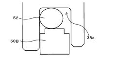
- FIG. It is sectional drawing of the seal ring 50B of a modification. It is a sectional view of seal ring 50C of a modification.
- FIG. 1 is a block diagram schematically showing the configuration of a power transmission device 20.
- the power transmission device 20, as shown in FIG. 1 transmits a motive power from a laterally mounted engine (not shown) whose crankshaft is disposed substantially parallel to the axles 64a, 64b to the axles 64a, 64b.
- the torque converter 22 having a lockup clutch, which is configured as an axle device and includes an input-side pump impeller 22a connected to the engine crankshaft and an output-side turbine runner 22b, and a turbine runner 22b of the torque converter 22.
- a forward / backward switching unit 24 which outputs the connected power input with switching between forward rotation and reverse rotation, a primary shaft 32 connected to the forward / backward switching unit 24, and a secondary disposed parallel to the primary shaft 32 And a shaft 42 having a motion input to the primary shaft 32
- The comprises a continuously variable transmission (hereinafter referred to as "CVT") 30 for outputting to the secondary shaft 42 and steplessly, the.
- CVT continuously variable transmission
- the CVT 30 is hooked on a primary pulley 34 attached to the primary shaft 32, a secondary pulley 44 attached to the secondary shaft 42 disposed parallel to the primary shaft 32, a groove of the primary pulley 34 and a groove of the secondary pulley 44
- the power input to the primary shaft 32 is steplessly shifted and output to the secondary shaft 42 by changing the groove widths of the primary pulley 34 and the secondary pulley 44.
- the oil pump, the regulator valve for adjusting the oil pressure from the oil pump, and the oil pressure adjusted by the regulator valve are used. It is carried out by a hydraulic circuit comprising a control valve for connecting and disconnecting an oil passage for supplying and discharging hydraulic pressure to and from the primary cylinder 38 and the secondary cylinder 48, and a solenoid valve for driving the control valve. Since the secondary shaft 42 is connected to the left and right axles 64 a and 64 b via the gear mechanism 60 and the differential gear 62, power from the engine is torque converter 22, forward / reverse switching unit 24, CVT 40, and gear mechanism 60. , And the differential gear 62 sequentially transmits to the axles 64a and 64b.
- the primary pulley 34 is composed of a fixed sheave 35 integrally formed with the primary shaft 32 and a movable sheave 36 axially slidably supported on the primary shaft 32 via a ball spline.
- the secondary pulley 44 is configured by a fixed sheave 45 integrally formed with the secondary shaft 42, and a movable sheave 46 axially slidably supported on the secondary shaft 42 via a ball spline. .
- the movable sheave 46 of the secondary pulley 44 is biased by the return spring 47 in the direction to narrow the groove width of the secondary pulley 44.
- the movable sheave 36 of the primary pulley 34 is formed with a cylindrical portion 36 a so that the piston is integrated and extends in the axial direction on the cylinder 38 side from the outer peripheral portion.
- the outer peripheral portion thereof is radially extended to the vicinity of the inner peripheral surface of the cylindrical portion 36a of the movable sheave 36, and between the outer peripheral edge thereof and the inner peripheral surface of the cylindrical portion 36a of the movable sheave 36 (piston) Gap is sealed.
- the hydraulic pressure chamber 39 is formed.
- the movable sheave 46 of the secondary pulley 44 also has a cylindrical portion so that the piston is integrated and extends in the axial direction from the outer peripheral portion to the secondary cylinder 48 side.
- the outer peripheral portion thereof is radially extended to the vicinity of the inner peripheral surface of the cylindrical portion of the movable sheave 46, and the gap between the outer peripheral edge thereof and the inner peripheral surface of the cylindrical portion of the movable sheave 46 (piston) Is sealed.
- the hydraulic pressure chamber 49 is formed.
- a ring groove 38a is formed on the entire outer periphery of the primary cylinder 38, and a seal ring 50 is formed on the outer peripheral side of the ring groove 38a, and an O-ring 52 is formed on the inner peripheral side.
- Seal ring 50 is formed in a rectangular shape in cross section by a resin (for example, a fluorocarbon resin or the like) material
- O ring 52 is a rubber (for example, a fluororubber or the like) material having a higher elastic modulus than seal ring 50
- the cross section is formed in a circular shape.
- chamfering is performed by chamfering at a chamfering angle of about 45 degrees. The reason for chamfering the seal ring 50 will be described later.
- FIG. 2 is an explanatory view showing how the belt 40 bites into the primary pulley 34.
- the belt 40 opens on one side to the primary pulley 34 in the range of the biting angle ⁇ at which the biting of the belt 40 occurs.
- a bending force is exerted by the product of the applied force and the radius at which the belt 40 contacts the primary pulley 34. Since the bending force acts once each time the primary pulley 34 makes one rotation, the primary pulley 34 and the primary cylinder 38 are deformed with a cycle of once every one rotation.
- FIG. 1 is an explanatory view showing how the belt 40 bites into the primary pulley 34.
- FIG. 3 shows a state of deformation of the primary pulley 34 and the primary cylinder 38 in the CVT 30 of the embodiment.
- the broken line of FIG. 3 shows the state before a deformation
- the continuous line shows the state after a deformation
- the primary pulley 34 (movable sheave 36) is deformed in a direction in which the cylindrical portion 36a approaches the axial center in a section in which the belt 40 is engaged, and in a section in which the belt 40 is not engaged It deforms in the direction away from the axis center.
- primary cylinder 38 is deformed in the axial direction opposite to primary pulley 34 over the entire circumference.
- the distance between the bottom surface of the ring groove 38a of the primary cylinder 38 and the inner circumferential surface (sliding surface) of the movable sheave 36 changes with a cycle of once per rotation due to the deformation of the primary pulley 34 and the primary cylinder 38 as described above.
- the O-ring 52 having a modulus of elasticity higher than that of the seal ring 50 is squeezed in the radial direction. Considering that oil pressure is generated in the oil pressure chamber 39, the O ring 52 is radially pressed with the seal ring 50 and the side wall of the ring groove 38a of the primary cylinder 38 by the oil pressure of the oil pressure chamber 39. It will be crushed.
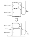
- FIG. 4 shows the deformation of the O-ring 52 when the seal ring 50 of the embodiment is used
- FIG. 5 shows the deformation of the O-ring 52 when the seal ring 150 of the comparative example is used.
- the seal ring 50 of the embodiment in which two places on the side in contact with the O-ring 52 among the four corners having a rectangular cross section are chamfered is used, and in FIG. 5, it is not chamfered.
- the seal ring 150 is used.
- since the seal ring 50 chamfers two corners on the side in contact with the O-ring 52, between the side wall of the ring groove 38 a and the side surface of the seal ring 50. Form a V-shaped groove (see A in FIG.
- the chamfering of two places on the side that is in contact with the O-ring 52 is the cycle of the O-ring 52 along with the deformation of the primary pulley 34 and the primary cylinder 38
- By providing a relief space through which the O-ring 52 flows when being crushed it is possible to suppress the occurrence of drag wear on the O-ring 52.
- FIG. 6 is an explanatory view for explaining how the primary pulley 134 and the primary cylinder 138 are deformed in the CVT of the comparative example.
- the broken line in FIG. 6 indicates the state before deformation, and the solid line indicates the state after deformation.
- the outer peripheral portion 138a of the primary cylinder 138 is formed in a cylindrical shape.
- the outer peripheral portion thereof is radially extended to the vicinity of the inner peripheral surface of the outer peripheral portion 138a of the primary cylinder, and the seal ring 50 and the O ring are formed in the ring groove 136a formed over the entire outer periphery.
- FIG. 7 shows the relationship between the rotation angle of the pulley 34 and the crushing margin of the O ring 52.
- FIG. 8 shows the relationship between the gear ratio, the engine torque, and the amplitude of the crushing margin of the O ring 52 in the CVT 30 of the embodiment.
- FIG. 9 shows the relationship between the transmission, the engine torque, and the amplitude of the crushing margin of the O-ring 52 in the continuously variable transmission of the comparative example.
- the continuous line of FIG. 7 shows the crushing margin of O ring 52 in an Example
- the dashed-dotted line shows the crushing margin of O ring 52 in a comparative example.
- the amplitude of the crush margin of the O-ring 52 based on the deformation of the primary pulley 34 and the primary cylinder 38 tends to be larger in the embodiment than in the comparative example, as shown in FIGS. 7-9. That is, in the embodiment, since the drag wear of the O-ring 52 is easily generated as compared with the comparative example, the significance of applying the present invention becomes larger.
- the seal ring having a rectangular cross section in the gap between the movable sheave 36 and the primary cylinder 38 forming the hydraulic chamber 39 on the back surface of the movable sheave 36
- the seal is mounted by mounting the O-ring 52 having a circular cross-section on the inner peripheral side in a layered manner on the outer peripheral side of 50 and the O-ring 52 on the inner peripheral side, Therefore, even if the O-ring 52 is periodically crushed by deformation of the primary pulley 34 (movable sheave 36) and the primary cylinder 38 by the belt 40, the side wall and seal of the ring groove 38a are chamfered.
- the O-ring 52 can be made to flow in the V-shaped groove formed between the side of the ring 50 and the O-ring 52, and the occurrence of the drag wear of the O-ring 52 is suppressed. It can be. As a result, the sealing performance can be secured without using the movable sheave 36 or the primary cylinder 38 having excessive rigidity.
- a cylindrical portion 36a axially extended from the outer peripheral portion of the movable sheave 36 is formed, and the outer peripheral portion of the primary cylinder 38 is radially extended to near the inner peripheral surface of the cylindrical portion 36a.
- a ring groove 38a is formed over the entire periphery of the outer periphery of the primary cylinder 38 by extending it, and the seal ring 50 and the O-ring 52 are respectively attached to the ring groove 38a in layers on the outer peripheral side and inner peripheral side
- the hydraulic chamber 39 is formed, as shown in FIG.
- the outer peripheral portion 138a of the primary cylinder 138 is formed in a cylindrical shape, and the outer peripheral portion of the movable sheave 136 is the inner peripheral of the outer peripheral portion 138a of the primary cylinder 138.
- the ring groove 136a is formed along the entire periphery of the outer periphery of the movable sheave 136, and the ring ring 136a and the seal ring 50 are formed.
- the outer peripheral side and inner peripheral side may be to form a hydraulic chamber 139.
- the significance of applying the present invention becomes slightly smaller.
- the chamfering of the seal ring 50 having a rectangular cross section is performed by planing with a chamfering angle of about 45 degrees, but the primary pulley 34 (movable sheave 36) and the primary cylinder
- the plane take-up angle is not limited to 45 degrees, and other chamfering angles such as 30 degrees, 40 degrees, 50 degrees, 60 degrees, etc. may be used.
- seal ring 50B of the modification of FIG. 10 It is not round, as shown in seal ring 50B of the modification of FIG. 10, or it is made round chamfer (R chamfering), as shown in seal ring 50C of the modification of FIG. Etc. or the type of L chamfer may as to any chamfered shape.
- seal structure of the continuously variable transmission of the four corners of the seal ring 50 having a rectangular cross section, two corners on the side to which the O-ring 52 abuts are chamfered.
- the seal ring 50 and the O-ring 52 are on the side wall of the ring groove 38 a of the primary cylinder 38 by the oil pressure of the oil pressure chamber 39 among the two places where the O ring 52 is in contact. It does not matter as what chamfers only one place of the side to be pressed.
- the seal ring 50 corresponds to the “outer peripheral seal member”
- the O-ring 52 corresponds to the “inner peripheral seal member”.
- the correspondence between the main elements of the embodiment and the main elements of the invention described in the section of the summary of the invention specifically illustrates the best mode for carrying out the invention described in the section of the summary of the invention.
- the invention is not limited to the elements of the invention described in the section of the summary of the invention, as it is an example to explain. That is, the interpretation of the invention described in the section of the summary of the invention should be made based on the description of the section, and the embodiment is only a specific example of the invention described in the section of the summary of the invention. It is.
- the present invention is applicable to the continuously variable transmission manufacturing industry.
Landscapes
- Engineering & Computer Science (AREA)
- General Engineering & Computer Science (AREA)
- Mechanical Engineering (AREA)
- Transmissions By Endless Flexible Members (AREA)
- Sealing Devices (AREA)
Abstract
Description
可動シーブと固定シーブとが対向して配置され入力軸と出力軸にそれぞれ連結された2つのプーリと、両プーリ間に掛け渡されたベルトと、前記可動シーブの背面に油圧室を形成するシリンダとを備え、前記シリンダ内に油圧を給排することにより前記可動シーブを移動させて前記プーリの溝幅を変更可能な無段変速機における、前記可動シーブと前記シリンダとの隙間をシールする無段変速機のシール構造であって、
前記可動シーブと前記シリンダの一方に形成された環状の溝に配置される環状の外周側シール部材と、
前記環状の溝に前記外周側シール部材よりも内周側に層状に配置され、前記外周側シール部材よりも高弾性の環状の内周側シール部材と、
を備え、
前記外周側シール部材は、前記内周側シール部材と当接している側が面取りされてなる
ことを要旨とする。
Claims (4)
- 可動シーブと固定シーブとが対向して配置され入力軸と出力軸にそれぞれ連結された2つのプーリと、両プーリ間に掛け渡されたベルトと、前記可動シーブの背面に油圧室を形成するシリンダとを備え、前記シリンダ内に油圧を給排することにより前記可動シーブを移動させて前記プーリの溝幅を変更可能な無段変速機における、前記可動シーブと前記シリンダとの隙間をシールする無段変速機のシール構造であって、
前記可動シーブと前記シリンダの一方に形成された環状の溝に配置される環状の外周側シール部材と、
前記環状の溝に前記外周側シール部材よりも内周側に層状に配置され、前記外周側シール部材よりも高弾性の環状の内周側シール部材と、
を備え、
前記外周側シール部材は、前記内周側シール部材と当接している側が面取りされてなる
ことを特徴とする無段変速機のシール構造。 - 請求項1記載のシール構造であって、
前記外周側シール部材は、平面取りにより面取りされてなる
ことを特徴とする無段変速機のシール構造。 - 請求項1または2記載のシール構造であって、
前記外周側シール部材は、断面が矩形状のシールリングであり、
前記内周側シール部材は、断面が円形状のOリングである
無段変速機のシール構造。 - 請求項1ないし3いずれか1項に記載のシール構造であって、
前記可動シーブは、外周部から軸方向に延伸された円筒部が形成され、
前記シリンダは、外周部が前記可動シーブの円筒部の内周面手前まで径方向に延伸され、
前記シール部材は、前記シリンダの外周縁に全周に亘って形成された溝に装着されてなる
無段変速機のシール構造。
Priority Applications (2)
| Application Number | Priority Date | Filing Date | Title |
|---|---|---|---|
| DE112011101544T DE112011101544T5 (de) | 2010-08-06 | 2011-07-08 | Dichtanordnung für ein stetig variables Getriebe |
| CN2011800322813A CN102959279A (zh) | 2010-08-06 | 2011-07-08 | 无级变速器的密封结构 |
Applications Claiming Priority (2)
| Application Number | Priority Date | Filing Date | Title |
|---|---|---|---|
| JP2010-177178 | 2010-08-06 | ||
| JP2010177178A JP2012036962A (ja) | 2010-08-06 | 2010-08-06 | 無段変速機のシール構造 |
Publications (1)
| Publication Number | Publication Date |
|---|---|
| WO2012017779A1 true WO2012017779A1 (ja) | 2012-02-09 |
Family
ID=45555578
Family Applications (1)
| Application Number | Title | Priority Date | Filing Date |
|---|---|---|---|
| PCT/JP2011/065661 Ceased WO2012017779A1 (ja) | 2010-08-06 | 2011-07-08 | 無段変速機のシール構造 |
Country Status (5)
| Country | Link |
|---|---|
| US (1) | US20120032405A1 (ja) |
| JP (1) | JP2012036962A (ja) |
| CN (1) | CN102959279A (ja) |
| DE (1) | DE112011101544T5 (ja) |
| WO (1) | WO2012017779A1 (ja) |
Families Citing this family (8)
| Publication number | Priority date | Publication date | Assignee | Title |
|---|---|---|---|---|
| US8871699B2 (en) | 2012-09-13 | 2014-10-28 | Ecolab Usa Inc. | Detergent composition comprising phosphinosuccinic acid adducts and methods of use |
| JP5942227B2 (ja) * | 2012-12-20 | 2016-06-29 | ジヤトコ株式会社 | 油圧アクチュエータ装置の製造方法 |
| KR101721347B1 (ko) * | 2012-12-20 | 2017-03-29 | 쟈트코 가부시키가이샤 | 유압 액추에이터 장치 |
| US9903474B2 (en) * | 2013-03-27 | 2018-02-27 | Kabushiki Kaisha Riken | Seal device |
| CN105889516A (zh) * | 2015-01-22 | 2016-08-24 | 贵州航空发动机研究所 | 一种液压作动筒的密封装置 |
| DE202015103420U1 (de) | 2015-06-29 | 2016-06-30 | Reinz-Dichtungs-Gmbh | Getriebesteuervorrichtung |
| JP7036944B2 (ja) * | 2018-10-22 | 2022-03-15 | ジヤトコ株式会社 | 車両用の無段変速機 |
| CN109812581A (zh) * | 2019-02-26 | 2019-05-28 | 浙江兰天机械密封件有限公司 | 一种干磨式组合密封装置 |
Citations (2)
| Publication number | Priority date | Publication date | Assignee | Title |
|---|---|---|---|---|
| JPH11257446A (ja) * | 1997-12-22 | 1999-09-21 | Luk Getriebe Syst Gmbh | 伝動装置 |
| JP2003501598A (ja) * | 1999-06-08 | 2003-01-14 | ドベルドベー.エス.シャムバン ヨーロッパ アクティーゼルスカブ | シール機構およびそのためのシール部材 |
Family Cites Families (31)
| Publication number | Priority date | Publication date | Assignee | Title |
|---|---|---|---|---|
| JP3223241B2 (ja) * | 1997-03-17 | 2001-10-29 | 本田技研工業株式会社 | ベルト式無段変速機 |
| US3642248A (en) * | 1969-05-07 | 1972-02-15 | Allen & Co Fof Proprietary Fun | Sealing mechanism |
| DE3320515C1 (de) * | 1983-06-07 | 1988-12-01 | Christensen, Inc., 84115 Salt Lake City, Utah | Hochdruckdichtung fuer laengsverschieblich gegeneinander bewegbare Teile von Tiefbohrwerkzeugen |
| GB2177464B (en) * | 1985-06-29 | 1988-06-02 | Dowty Seals Ltd | Sealing assembly |
| FR2590641B1 (fr) * | 1985-11-25 | 1989-07-13 | Snecma | Dispositif composite d'etancheite |
| JPS62190160U (ja) * | 1986-05-26 | 1987-12-03 | ||
| US5149107A (en) * | 1989-03-29 | 1992-09-22 | W. S. Shamban & Company | Elastomer energized sealing and exclusion device |
| US5071142A (en) * | 1989-03-31 | 1991-12-10 | Leber Corporation | Bi-directional substantially zero leakage path sealing assembly |
| US5197746A (en) * | 1989-03-31 | 1993-03-30 | Leber Corporation | Substantially zero leakage path sealing assembly with expander void |
| DE4140833C3 (de) * | 1991-04-30 | 1995-03-16 | Busak & Luyken Gmbh & Co | Dichtungsanordnung |
| CA2076912C (en) * | 1991-08-28 | 1999-05-04 | Jerry F. Carlin | Hydraulic cylinder and improved wear ring assembly for use therein |
| US5291974A (en) * | 1992-08-24 | 1994-03-08 | Livernois Automation Company | High pressure self-contained gas spring or die cylinder and sealing arrangement therefor |
| JP3961039B2 (ja) * | 1994-12-06 | 2007-08-15 | ルーク ゲトリーベ−ジステーメ ゲゼルシャフト ミット ベシュレンクテル ハフツング | トルクセンサ及び円錐形プーリー巻掛け式伝動装置 |
| US5725221A (en) * | 1994-12-27 | 1998-03-10 | Ford Global Technologies, Inc. | Two piece seal |
| DE19739472A1 (de) * | 1997-09-09 | 1999-03-18 | Freudenberg Carl Fa | Dichtungsanordnung |
| DE19909347B4 (de) * | 1998-03-10 | 2012-03-29 | Schaeffler Technologies Gmbh & Co. Kg | Getriebe |
| US6454272B1 (en) * | 1999-06-08 | 2002-09-24 | W. S. Shamban Europa A/S | Sealing arrangement and a sealing member therefor |
| DE10117662C1 (de) * | 2001-04-09 | 2003-01-16 | Freudenberg Carl Kg | Stangen- oder Kolbenprimärdichtung |
| DE10145914A1 (de) * | 2001-09-18 | 2003-05-08 | Busak & Shamban Gmbh | Hochdruckdichtungsanordnung |
| JP2005530110A (ja) * | 2002-06-17 | 2005-10-06 | ルーク ラメレン ウント クツプルングスバウ ベタイリグングス コマンディートゲゼルシャフト | 円錐形ディスク式巻掛け伝動装置 |
| US20040084850A1 (en) * | 2002-11-04 | 2004-05-06 | Brian Lang | Annular seal |
| US6905144B2 (en) * | 2003-07-02 | 2005-06-14 | Delaware Capital Formation | Spring-loaded ‘L’-shaped seal ring |
| DE10354704A1 (de) * | 2003-11-22 | 2005-06-16 | Zf Transmission Technologies L.L.C., Batavia | Verfahren zur Montage eines Kegelscheibenumschlingungsgetriebes |
| DE102006009491A1 (de) * | 2006-02-27 | 2007-09-06 | Busak + Shamban Deutschland Gmbh | Dichtungssystem mit Druckentlastungselementen und Verwendung eines Dichtungssystems zur Einstellung einer Zwischenraumdruckkaskade |
| DE102006023157B3 (de) * | 2006-05-16 | 2008-01-24 | Trelleborg Sealing Solutions Germany Gmbh | Dichtungsanordnung zur Druckentlastung |
| JP2008190650A (ja) * | 2007-02-06 | 2008-08-21 | Ntn Corp | シールリング |
| US7828301B2 (en) * | 2008-01-25 | 2010-11-09 | Intelliserv, Llc | Self-energized backup ring for annular seals |
| JP5072671B2 (ja) * | 2008-03-18 | 2012-11-14 | ダイハツ工業株式会社 | ベルト式無段変速機の組立構造 |
| JP2009275718A (ja) | 2008-05-12 | 2009-11-26 | Toyota Motor Corp | 無段変速機 |
| JP4670904B2 (ja) * | 2008-05-30 | 2011-04-13 | トヨタ自動車株式会社 | 無段変速機 |
| CN201265652Y (zh) * | 2008-08-13 | 2009-07-01 | 广州机械科学研究院 | 孔用异形密封圈 |
-
2010
- 2010-08-06 JP JP2010177178A patent/JP2012036962A/ja active Pending
-
2011
- 2011-07-08 CN CN2011800322813A patent/CN102959279A/zh active Pending
- 2011-07-08 WO PCT/JP2011/065661 patent/WO2012017779A1/ja not_active Ceased
- 2011-07-08 DE DE112011101544T patent/DE112011101544T5/de not_active Withdrawn
- 2011-08-01 US US13/195,377 patent/US20120032405A1/en not_active Abandoned
Patent Citations (2)
| Publication number | Priority date | Publication date | Assignee | Title |
|---|---|---|---|---|
| JPH11257446A (ja) * | 1997-12-22 | 1999-09-21 | Luk Getriebe Syst Gmbh | 伝動装置 |
| JP2003501598A (ja) * | 1999-06-08 | 2003-01-14 | ドベルドベー.エス.シャムバン ヨーロッパ アクティーゼルスカブ | シール機構およびそのためのシール部材 |
Also Published As
| Publication number | Publication date |
|---|---|
| DE112011101544T5 (de) | 2013-03-07 |
| US20120032405A1 (en) | 2012-02-09 |
| CN102959279A (zh) | 2013-03-06 |
| JP2012036962A (ja) | 2012-02-23 |
Similar Documents
| Publication | Publication Date | Title |
|---|---|---|
| US20120032405A1 (en) | Sealing structure for continuously variable transmission | |
| JP3248615B2 (ja) | ベルト式無段変速機のプーリ用シリンダ構造 | |
| US9279475B2 (en) | Element for metallic belt | |
| CN105264268B (zh) | 带式无级变速装置 | |
| CN103459890B (zh) | 带式无级变速器 | |
| US8864610B2 (en) | Belt type continuously variable transmission for vehicle | |
| JP7001837B2 (ja) | 無段変速機 | |
| JP7036944B2 (ja) | 車両用の無段変速機 | |
| US20160208895A1 (en) | Structure for securing transmission stator shaft | |
| US8617026B2 (en) | Face spline clutch | |
| CN104334918B (zh) | 金属带用元件 | |
| CN105051423A (zh) | 带式无级变速器中的轴支承构造 | |
| JP2012097867A (ja) | 回転軸のシール構造 | |
| EP1582773A2 (en) | Pulley structure | |
| JP6366645B2 (ja) | ベアリングの潤滑構造 | |
| JP6552382B2 (ja) | 動力分割式無段変速機 | |
| JP6708102B2 (ja) | 車両用シンクロメッシュ機構の油圧装置 | |
| JP7382380B2 (ja) | 変速機 | |
| CN107869568B (zh) | 用于车辆的带式无级变速器 | |
| JP2018071746A (ja) | 車両用無段変速機 | |
| JP6537844B2 (ja) | 無段変速機 | |
| JP4752338B2 (ja) | シールリング | |
| JP6277026B2 (ja) | プーリ機構,プーリ機構を有する変速機及びこれを備えた車両 | |
| JP6381394B2 (ja) | 動力分割式無段変速機 | |
| JP6654931B2 (ja) | 可動装置および無段変速機 |
Legal Events
| Date | Code | Title | Description |
|---|---|---|---|
| WWE | Wipo information: entry into national phase |
Ref document number: 201180032281.3 Country of ref document: CN |
|
| 121 | Ep: the epo has been informed by wipo that ep was designated in this application |
Ref document number: 11814409 Country of ref document: EP Kind code of ref document: A1 |
|
| WWE | Wipo information: entry into national phase |
Ref document number: 112011101544 Country of ref document: DE Ref document number: 1120111015445 Country of ref document: DE |
|
| 122 | Ep: pct application non-entry in european phase |
Ref document number: 11814409 Country of ref document: EP Kind code of ref document: A1 |