WO2012017776A1 - 波長変換部材の製造方法、波長変換部材及び光源 - Google Patents
波長変換部材の製造方法、波長変換部材及び光源 Download PDFInfo
- Publication number
- WO2012017776A1 WO2012017776A1 PCT/JP2011/065566 JP2011065566W WO2012017776A1 WO 2012017776 A1 WO2012017776 A1 WO 2012017776A1 JP 2011065566 W JP2011065566 W JP 2011065566W WO 2012017776 A1 WO2012017776 A1 WO 2012017776A1
- Authority
- WO
- WIPO (PCT)
- Prior art keywords
- wavelength conversion
- conversion member
- inorganic phosphor
- light
- light source
- Prior art date
- Legal status (The legal status is an assumption and is not a legal conclusion. Google has not performed a legal analysis and makes no representation as to the accuracy of the status listed.)
- Ceased
Links
Images

Classifications
-
- C—CHEMISTRY; METALLURGY
- C03—GLASS; MINERAL OR SLAG WOOL
- C03B—MANUFACTURE, SHAPING, OR SUPPLEMENTARY PROCESSES
- C03B23/00—Re-forming shaped glass
- C03B23/04—Re-forming tubes or rods
- C03B23/047—Re-forming tubes or rods by drawing
-
- C—CHEMISTRY; METALLURGY
- C03—GLASS; MINERAL OR SLAG WOOL
- C03B—MANUFACTURE, SHAPING, OR SUPPLEMENTARY PROCESSES
- C03B19/00—Other methods of shaping glass
- C03B19/06—Other methods of shaping glass by sintering, e.g. by cold isostatic pressing of powders and subsequent sintering, by hot pressing of powders, by sintering slurries or dispersions not undergoing a liquid phase reaction
- C03B19/063—Other methods of shaping glass by sintering, e.g. by cold isostatic pressing of powders and subsequent sintering, by hot pressing of powders, by sintering slurries or dispersions not undergoing a liquid phase reaction by hot-pressing powders
-
- C—CHEMISTRY; METALLURGY
- C03—GLASS; MINERAL OR SLAG WOOL
- C03C—CHEMICAL COMPOSITION OF GLASSES, GLAZES OR VITREOUS ENAMELS; SURFACE TREATMENT OF GLASS; SURFACE TREATMENT OF FIBRES OR FILAMENTS MADE FROM GLASS, MINERALS OR SLAGS; JOINING GLASS TO GLASS OR OTHER MATERIALS
- C03C14/00—Glass compositions containing a non-glass component, e.g. compositions containing fibres, filaments, whiskers, platelets, or the like, dispersed in a glass matrix
- C03C14/004—Glass compositions containing a non-glass component, e.g. compositions containing fibres, filaments, whiskers, platelets, or the like, dispersed in a glass matrix the non-glass component being in the form of particles or flakes
-
- C—CHEMISTRY; METALLURGY
- C09—DYES; PAINTS; POLISHES; NATURAL RESINS; ADHESIVES; COMPOSITIONS NOT OTHERWISE PROVIDED FOR; APPLICATIONS OF MATERIALS NOT OTHERWISE PROVIDED FOR
- C09K—MATERIALS FOR MISCELLANEOUS APPLICATIONS, NOT PROVIDED FOR ELSEWHERE
- C09K2211/00—Chemical nature of organic luminescent or tenebrescent compounds
- C09K2211/10—Non-macromolecular compounds
- C09K2211/1003—Carbocyclic compounds
- C09K2211/1014—Carbocyclic compounds bridged by heteroatoms, e.g. N, P, Si or B
-
- H—ELECTRICITY
- H10—SEMICONDUCTOR DEVICES; ELECTRIC SOLID-STATE DEVICES NOT OTHERWISE PROVIDED FOR
- H10H—INORGANIC LIGHT-EMITTING SEMICONDUCTOR DEVICES HAVING POTENTIAL BARRIERS
- H10H20/00—Individual inorganic light-emitting semiconductor devices having potential barriers, e.g. light-emitting diodes [LED]
- H10H20/80—Constructional details
- H10H20/85—Packages
- H10H20/851—Wavelength conversion means
- H10H20/8511—Wavelength conversion means characterised by their material, e.g. binder
Definitions
- the present invention relates to a method for manufacturing a wavelength conversion member, a wavelength conversion member manufactured by the method, and a light source including the same.
- the present invention relates to a method for manufacturing a wavelength conversion member in which an inorganic phosphor powder is dispersed in a glass base material, a wavelength conversion member manufactured by the method, and a light source including the same.
- white light sources used for applications such as backlights for liquid crystal displays have been actively developed.
- a white light source for example, in Patent Document 1 below, a part of light from an LED is absorbed on the light emitting side of an LED (Light Emitting Diode) that emits blue light, and yellow light is emitted.
- LED Light Emitting Diode
- a light source in which a wavelength conversion member is arranged is disclosed. This light source can emit white light by combining blue light and yellow light.
- the wavelength conversion member As this wavelength conversion member, a material in which an inorganic phosphor powder is dispersed in a resin matrix has been conventionally used.
- the resin deteriorates due to the light from the LED, and the luminance of the white light source tends to decrease with time.
- the light from the LED is a light having a short wavelength such as blue light and a strong energy
- the resin is likely to deteriorate.
- Patent Documents 2 and 3 propose a wavelength conversion member in which an inorganic phosphor powder is dispersed in glass.
- the wavelength conversion members described in Patent Documents 2 and 3 do not contain a resin and are composed only of an inorganic solid, and thus have excellent heat resistance and weather resistance. Therefore, by using this wavelength conversion member, it is possible to realize a white light source whose luminance is not easily lowered.
- a wavelength conversion member using glass as a dispersion medium has a problem that it is difficult to mold compared to a wavelength conversion member using resin as a dispersion medium. In particular, it is difficult to form a wavelength conversion member using glass as a dispersion medium into a plate shape.
- Patent Document 4 proposes a method for producing a plate-shaped wavelength conversion member by producing a green sheet from a paste containing glass powder and inorganic phosphor powder, and firing the green sheet. .
- the wavelength conversion member manufacturing method described in Patent Document 4 has a problem that it is difficult to easily manufacture a high-intensity wavelength conversion member.
- the present invention has been made in view of the above points, and an object thereof is to provide a method of manufacturing a wavelength conversion member that can easily manufacture a high-intensity wavelength conversion member.
- the strength of the sintered body can be increased by heating and stretching the sintered body preform of the inorganic phosphor powder and the glass powder. It came to be accomplished.
- the wavelength conversion member is formed by heating and stretching a sintered body preform of inorganic phosphor powder and glass powder. For this reason, a high intensity
- the heating and stretching of the sintered body preform is performed at a temperature not lower than the softening point of the glass powder and not higher than 200 ° C. higher than the softening point of the glass powder.
- heating and stretching of the sintered body preform can be suitably performed.
- a wavelength conversion member with higher strength can be manufactured.
- when there is much content of the inorganic fluorescent substance in a sintered compact preform for example, when it is 5 mass% or more, especially 8 mass% or more, it is 100 degreeC or more from the softening point of glass powder, especially 150 degreeC. It is preferable to perform heat stretching at a higher temperature.
- a sintered body preform by forming a molded body containing an inorganic phosphor and glass powder and not containing a binder, and firing the molded body in a reduced-pressure atmosphere.
- voids in the sintered body preform can be reduced. Accordingly, it is possible to manufacture a wavelength conversion member with higher strength.
- the wavelength conversion member according to the present invention is obtained by heat-stretching a sintered preform of inorganic phosphor powder and glass powder. As described above, the strength of the sintered body can be increased by subjecting the sintered body preform to heat-stretching. Therefore, the wavelength conversion member according to the present invention has high strength.
- the shape of the wavelength conversion member according to the present invention is not particularly limited.
- the wavelength conversion member according to the present invention may be, for example, a plate shape or a rod shape.
- the wavelength conversion member according to the present invention may have a plate shape in which the ratio of the length dimension to the thickness dimension is 100: 1 or more.
- plate shape includes “sheet shape” and “film shape”.
- the average number of linear grooves having a length of 30 ⁇ m or more and a depth of 0.05 ⁇ m or more per 0.25 mm 2 is preferably 100 or less, It is more preferably 50 or less, further preferably 20 or less, still more preferably 10 or less, and particularly preferably substantially absent.
- cracks due to the linear grooves are less likely to occur on the surface of the wavelength conversion member due to external pressure, and the problem of cracking and strength reduction is less likely to occur.
- light scattering loss due to the linear grooves is reduced. For this reason, the loss on the surface of the wavelength conversion member is reduced, and the light extraction efficiency is increased. As a result, it is possible to obtain a wavelength conversion member having a high light emission intensity and having very small variations in color reproducibility and light emission intensity.
- the length of the linear groove can be measured, for example, by observing an image of the wavelength conversion member surface using a scanning electron microscope (SEM). Further, the depth of the linear groove can be measured using, for example, a stylus type surface roughness meter.
- the depth of the linear groove refers to the distance from the average line to the tip of the linear groove in the measurement curve of the member surface shape.
- the inorganic phosphor powder can be appropriately selected according to required excitation light, converted light, and the like.
- examples of inorganic phosphor powders include oxide inorganic phosphors, nitride inorganic phosphors, oxynitride inorganic phosphors, sulfide inorganic phosphors, oxysulfide inorganic phosphors, rare earth sulfide inorganic phosphors, and aluminate chlorides. 1 type or more selected from inorganic phosphors and halophosphate inorganic phosphors.
- the light source according to the present invention includes the wavelength conversion member according to the present invention and a light emitting element that emits excitation light of the wavelength conversion member with respect to the wavelength conversion member.
- the wavelength conversion member according to the present invention has high strength. Therefore, the light source according to the present invention has high mechanical durability.
- the light emitting element is not particularly limited, and can be constituted by, for example, an LED.
- the LED By using the LED, a long product life and low power consumption can be realized.
- the light source according to the present invention may emit light of any color tone.
- the light source according to the present invention includes, for example, a light emitting element that emits blue light and a wavelength conversion member that absorbs blue light from the LED and emits yellow light, and emits white light by combining blue light and yellow light. It may be emitted.
- the light source according to the present invention may include a plurality of light emitting elements.
- blue light refers to light in the wavelength range of 440 nm to 480 nm.
- White light refers to light having a chromaticity x of 0.25 to 0.45 and a chromaticity y of 0.25 to 0.45. In particular, light close to the locus of black body radiation is preferable.
- a method for manufacturing a wavelength conversion member capable of easily manufacturing a high-intensity wavelength conversion member.
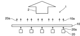
- FIG. 1 is a schematic side view of a light source according to an embodiment of the present invention.
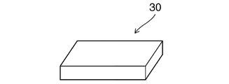
- FIG. 2 is a schematic perspective view of a sintered body preform.
- FIG. 3 is a schematic side view for explaining the heating and stretching step.
- the present invention is implemented using the light source 1 shown in FIG. 1 as an example.
- the light source 1 is merely an example.
- the light source and the wavelength conversion member according to the present invention are not limited to the light source 1 and the wavelength conversion member 10 included in the light source 1.
- FIG. 1 is a schematic side view of a light source according to the present embodiment.
- the light source 1 includes a wavelength conversion member 10 and a plurality of light emitting elements 20.
- a part of the excitation light 20 a emitted from the light emitting element 20 is absorbed by the wavelength conversion member 10, and the fluorescence 10 a is emitted from the wavelength conversion member 10 accordingly.
- a part of the excitation light 20a is transmitted as it is without being absorbed by the wavelength conversion member 10, and a combined light 2 (for example, white light) of the transmitted excitation light 20a and fluorescence 10a is emitted.
- a combined light 2 for example, white light
- the light emitting element 20 is not particularly limited, and can be constituted by, for example, an LED, a plasma light emitting element, an electroluminescence light emitting element, or the like.
- the wavelength conversion member 10 is formed by dispersing inorganic phosphor powder in glass.
- the inorganic phosphor powder can be appropriately selected according to the wavelength of the synthesized light 2 to be emitted from the light source 1, the wavelength of the excitation light 20a emitted from the light emitting element 20, or the like.
- examples of inorganic phosphor powders include oxide inorganic phosphors, nitride inorganic phosphors, oxynitride inorganic phosphors, sulfide inorganic phosphors, oxysulfide inorganic phosphors, rare earth sulfide inorganic phosphors, and aluminate chlorides. Inorganic phosphors and halophosphate inorganic phosphors can be used.
- Inorganic phosphor powders that emit blue light when irradiated with ultraviolet to near-ultraviolet excitation light having a wavelength of 300 to 440 nm include Sr 5 (PO 4 ) 3 Cl: Eu 2+ , (Sr, Ba) MgAl 10 O 17 : Eu 2+ , (Sr, Ba) 3 MgSi 2 O 8 : Eu 2+ and the like.
- Inorganic phosphor powders that emit green fluorescence (fluorescence having a wavelength of 500 nm to 540 nm) when irradiated with excitation light having a wavelength of 300 to 440 nm include SrAl 2 O 4 : Eu 2+ and SrGa 2 S 4 : Eu.
- Inorganic phosphor powders that emit green fluorescence (fluorescence having a wavelength of 500 nm to 540 nm) when irradiated with blue excitation light having a wavelength of 440 to 480 nm include SrAl 2 O 4 : Eu 2+ , SrGa 2 S 4 : Eu 2+ , SrBaSiO 4 : Eu 2+ , CdS: In, CaS: Ce 3+ , Y 3 (Al, Gd) 5 O 12 : Ce 2+ , Ca 3 Sc 2 Si 3 O 12 : Ce 3+ , SrSiOn: Eu 2+ and the like.
- non-fluorescent powder that emits yellow fluorescence (fluorescence having a wavelength of 540 nm to 595 nm) when irradiated with excitation light having a wavelength of 300 to 440 nm
- Sr 3 WO 6 U
- SrSO 4 Eu 2+
- ZnS P
- ZnS P 3 ⁇ , Cl ⁇
- ZnS Mn 2+ and the like.
- Examples of inorganic phosphor powder that emits red fluorescence (fluorescence having a wavelength of 600 nm to 700 nm) when irradiated with ultraviolet to near ultraviolet excitation light having a wavelength of 300 to 440 nm include CaS: Yb 2+ , Cl, Gd 3 Ga 4 O 12 : Cr 3+ , CaGa 2 S 4 : Mn 2+ , Na (Mg, Mn) 2 LiSi 4 O 10 F 2 : Mn, ZnS: Sn 2+ , Y 3 Al 5 O 12 : Cr 3+ , SrB 8 O 13 : Sm 2+ , MgSr 3 Si 2 O 8 : Eu 2+ , Mn 2+ , ⁇ -SrO.3B 2 O 3 : Sm 2+ , ZnS—CdS, ZnSe: Cu + , Cl, ZnGa 2 S 4 : Mn 2+ , ZnO: Bi 3+ , BaS : Au, K
- Inorganic phosphor powders that emit red fluorescence (fluorescence having a wavelength of 600 nm to 700 nm) when irradiated with blue excitation light having a wavelength of 440 to 480 nm include ZnS: Mn 2+ , Te 2+ , Mg 2 TiO 4 : Mn 4+ , K 2 SiF 6 : Mn 4+ , SrS: Eu 2+ , CaS: Eu 2+ , Na 1.23 K 0.42 Eu 0.12 TiSi 4 O 11 , Na 1.23 K 0.42 Eu 0.12 TiSi 5 O 13 : Eu 3+ , CdS: In, Te, CaAlSiN 3 : Eu 2+ , CaSiN 3 : Eu 2+ , (Ca, Sr) 2 Si 5 N 8 : Eu 2+ , Eu 2 W 2 O 7 and the like.
- a plurality of inorganic phosphor powders may be mixed and used in accordance with the wavelength range of excitation light or light emission. For example, when white light is obtained by irradiation with ultraviolet excitation light, inorganic phosphor powders emitting blue, green, and red fluorescence may be mixed and used.
- a white light source 1 useful as a light source of a liquid crystal display is realized by using an LED that emits blue light as the light emitting element 20 and using a wavelength conversion member 10 that absorbs blue light and emits yellow light. Can do.
- the glass as the dispersion medium is not particularly limited as long as it can stably hold the inorganic phosphor powder.
- Specific examples of the glass that can be used as the dispersion medium include, for example, silicate glass, borate glass, SiO 2 —B 2 O 3 —RO glass (R is at least Mg, Ca, Sr, and Ba).
- Borosilicate glass such as SnO—P 2 O 5 glass, borophosphate glass and the like. Of these, SiO 2 —B 2 O 3 —RO glass and SnO—P 2 O 5 glass are preferably used.
- the SiO 2 —B 2 O 3 —RO glass is, for example, in mol%, SiO 2 30 to 80%, B 2 O 3 1 to 30%, MgO 0 to 10%, CaO 0 to 30%, SrO 0 to It may be a glass containing a composition of 20%, BaO 0 to 40%, MgO + CaO + SrO + BaO 5 to 45%, Al 2 O 3 0 to 10% and ZnO 0 to 10%.
- the SiO 2 —B 2 O 3 —RO glass reduces the softening point of glass such as alkali metal oxides such as Li 2 O, Na 2 O, K 2 O, etc.
- Components that enable firing, components that improve the meltability of glass such as P 2 O 5, and chemicals of glasses such as Ta 2 O 5 , TiO 2 , Nb 2 O 5 , Gd 2 O 3 , and La 2 O 3 It may further contain a component for improving durability.
- SnO—P 2 O 5 glass is, for example, mol%, SnO 35-80%, P 2 O 5 5-40%, B 2 O 3 0-30%, Al 2 O 3 0-10%, SiO 2 2 0 ⁇ 10%, Li 2 O 0 ⁇ 10%, Na 2 O 0 ⁇ 10%, K 2 O 0 ⁇ 10%, MgO 0 ⁇ 10%, CaO 0 ⁇ 10%, SrO 0 ⁇ 10% , and BaO 0 It may be a glass containing ⁇ 10% composition.
- SnO—P 2 O 5 glass includes components that improve weather resistance such as Ta 2 O 5 , TiO 2 , Nb 2 O 5 , Gd 2 O 3 , La 2 O 3 , ZnO It may further contain a component that stabilizes the glass.
- the molar ratio of SnO to P 2 O 5 is in the range of 0.9 to 16 It is preferably within the range of 1.5 to 10, more preferably within the range of 1.5 to 10, and even more preferably within the range of 2 to 5.
- the molar ratio (SnO / P 2 O 5 ) is too small, firing at a low temperature becomes difficult, and the inorganic phosphor powder may be easily deteriorated during firing.
- the weather resistance may be too low.
- the molar ratio (SnO / P 2 O 5 ) is too large, the glass tends to be devitrified, and the transmittance of the glass may be too low.
- the content of the inorganic phosphor powder in the wavelength conversion member 10 is not particularly limited, but is preferably 0.01% by mass to 30% by mass, for example, and more preferably 0.1% by mass to 25% by mass. It is preferably 1% by mass to 20% by mass.
- the shape of the wavelength conversion member 10 is not particularly limited.
- the wavelength conversion member 10 may be, for example, a plate shape or a rod shape.
- the wavelength conversion member 10 has a plate shape in which the ratio of the length dimension to the thickness dimension is 100: 1 or more will be described.
- a so-called binder-free molded body containing an inorganic phosphor powder and a glass powder and containing no binder is prepared.
- the molded body can be produced, for example, by press-molding a mixed powder of inorganic phosphor powder and glass powder using a mold.
- the average particle diameter D50 of the inorganic phosphor powder is preferably 1 ⁇ m to 50 ⁇ m, and more preferably 5 ⁇ m to 25 ⁇ m. If the average particle diameter D50 of the inorganic phosphor powder is too small, the emission intensity tends to decrease. On the other hand, if the average particle diameter D50 of the inorganic phosphor powder is too large, the uniformity of the luminescent color tends to decrease.
- the average particle diameter D50 of the glass powder is preferably 0.1 ⁇ m to 100 ⁇ m, and more preferably 1 ⁇ m to 50 ⁇ m. If the average particle diameter D50 of the glass powder is too small, bubbles are likely to be generated during firing. For this reason, the intensity
- the average particle diameter D50 is a value measured according to JIS-R1629 using SALD200J manufactured by Shimadzu Corporation.
- the produced compact is fired in a reduced-pressure atmosphere to form a sintered compact preform 30 shown in FIG.
- the pressure of the atmosphere in the firing step is preferably less than 1 atm, for example, because bubbles hardly remain in the sintered body preform.
- the maximum firing temperature can be, for example, about the softening point of the glass powder to the softening point + 100 ° C.
- the sintered compact preform 30 is also plate-shaped, a rectangular parallelepiped shape, or a cube shape.
- the wavelength conversion member 10 is formed by heating and stretching the obtained sintered body preform 30. Specifically, as shown in FIG. 3, the end of the sintered body preform 30 is pulled by a roller 32 in a state where the sintered body preform 30 is heated and softened by the heater 31. Thereby, the softened sintered body preform 30 is stretched, and the wavelength conversion member 10 is formed.
- the heating and stretching of the sintered body preform 30 is preferably performed at a temperature not less than the softening point of the glass powder and not more than 200 ° C. higher than the softening point of the glass powder.
- the ratio (t1 / t0) of the thickness t1 after stretching to the thickness t0 of the sintered body preform 30 before stretching is not particularly limited, but can be, for example, about 5 to 50.
- the wavelength conversion member 10 is formed by heating and stretching the sintered body preform 30. For this reason, the high intensity
- a compressive stress layer (for example, a layer having a compressive stress of about 0.1 MPa to 10 MPa) is formed on the surface layer of the wavelength conversion member 10 by heat stretching.
- the surface layer of the sintered body preform 30 is softened, so that the surface layer is repaired. Accordingly, in the manufactured wavelength conversion member 10, the average number of linear grooves having a length of 30 ⁇ m or more and a depth of 0.05 ⁇ m or more per 0.25 mm 2 is 100 or less on the surface of the wavelength conversion member 10. It is preferably 50 or less, more preferably 20 or less, still more preferably 10 or less, and particularly preferably substantially absent.
- the heat-stretching of the sintered compact preform 30 is performed at a temperature not lower than the softening point of the glass powder and not higher than 200 ° C. higher than the softening point of the glass powder. For this reason, the wavelength conversion member 10 of higher intensity
- the heating and stretching temperature of the sintered body preform 30 is too low, the heating and stretching cannot be suitably performed, and the strength of the obtained wavelength conversion member 10 may be lowered.
- the heating and stretching temperature of the sintered body preform 30 is too high, the wavelength conversion member 10 having a desired shape may not be obtained.
- the binder-free molded body is fired in a reduced-pressure atmosphere.
- the porosity of the sintered compact preform 30 and by extension, the wavelength conversion member 10 can be made low. Therefore, it is possible to manufacture the wavelength conversion member 10 having higher strength and higher luminous efficiency.
- the porosity of the sintered body preform 30 and the wavelength conversion member 10 is preferably 2% by volume or less, and more preferably 1% by volume or less.
- each shape of the sintered compact preform 30 and the wavelength conversion member 10 is not limited to a plate shape.
- Example 2 The following glass powder and inorganic phosphor powder are mixed so that the mass ratio (glass powder: inorganic phosphor powder) is 9: 1, and press molded using a mold to obtain a molded body. Produced. Thereafter, the compact was fired under the following conditions to produce a sintered body preform.
- composition (mass ratio) of glass powder SiO 2 50%, BaO 25%, CaO 10%, B 2 O 3 5%, Al 2 O 3 5%, ZnO 5% Average particle diameter of glass powder (D50): 3 ⁇ m
- Softening point of glass powder 850 ° C
- Composition of inorganic phosphor powder Y 3 (Al, Gd) 5 O 12 : Ce 2+ Average particle size (D50) of inorganic phosphor powder: 20 ⁇ m
- the obtained sintered body was cut into a rectangular parallelepiped shape having a width of 15 mm, a thickness of 4.5 mm, and a length of 100 mm to produce a base material.
- this base material is set in a stretch molding machine, carried into a molding furnace maintained at 1020 ° C. (softening point + 170 ° C.) at a feed rate of 1 mm / min, and pulled out from the molding furnace outlet at a rate of 225 mm / min. It was.
- the drawn molded body was cut with an automatic cutting machine to prepare a rectangular long wavelength conversion member having a width of 1 mm, a thickness of 0.3 mm, and a length of 300 mm. When this wavelength conversion member was irradiated with light from a blue LED (emission wavelength: 460 nm), white light emission was confirmed.
- the three-point bending strength of the wavelength conversion member obtained in this example was 250 MPa when measured according to JIS-R1601 using an autograph AG-10kNIS manufactured by Shimadzu Corporation.
- the three-point bending strength of the obtained wavelength conversion member was measured by the same method as in the above example and found to be 130 MPa.
- a high-intensity wavelength conversion member can be produced by heating and stretching the sintered body preform.
Landscapes
- Chemical & Material Sciences (AREA)
- Engineering & Computer Science (AREA)
- Materials Engineering (AREA)
- Organic Chemistry (AREA)
- Dispersion Chemistry (AREA)
- Chemical Kinetics & Catalysis (AREA)
- General Chemical & Material Sciences (AREA)
- Geochemistry & Mineralogy (AREA)
- Life Sciences & Earth Sciences (AREA)
- Ceramic Engineering (AREA)
- Manufacturing & Machinery (AREA)
- Led Device Packages (AREA)
- Luminescent Compositions (AREA)
- Optical Filters (AREA)
Abstract
高強度の波長変換部材を容易に製造することができる波長変換部材の製造方法を提供する。 無機蛍光体粉末とガラス粉末との焼結体プリフォーム30を加熱延伸することにより波長変換部材10を成形する。
Description
本発明は、波長変換部材の製造方法、その方法により製造された波長変換部材及びそれを備える光源に関する。特に、本発明は、ガラス母材中に無機蛍光体粉末が分散している波長変換部材を製造する方法、その方法により製造された波長変換部材及びそれを備える光源に関する。
近年、例えば、液晶ディスプレイのバックライトなどの用途に用いられる白色光源の開発が盛んに行われている。そのような白色光源の一例として、例えば下記の特許文献1には、青色光を出射するLED(Light Emitting Diode)の光出射側にLEDからの光の一部を吸収し、黄色の光を出射する波長変換部材を配置した光源が開示されている。この光源は、青色光と黄色光の合成により白色光を発することができる。
この波長変換部材としては、従来、樹脂マトリクス中に無機蛍光体粉末を分散させたものが使用されていた。しかしながら、樹脂マトリクス中に無機蛍光体粉末を分散させた波長変換部材では、LEDからの光により樹脂が劣化し、白色光源の輝度が経時的に低くなりやすいという問題がある。特に、LEDからの光が、青色光などの波長の短く、エネルギーが強い光である場合は、樹脂が劣化しやすい。
このような問題に鑑み、例えば、下記の特許文献2,3には、ガラス中に無機蛍光体粉末を分散させた波長変換部材が提案されている。特許文献2,3に記載の波長変換部材は、樹脂を含まず、無機固体のみから構成されるため、優れた耐熱性及び耐候性を有している。従って、この波長変換部材を用いることにより輝度が低下しにくい白色光源を実現することができる。
しかしながら、ガラスを分散媒として用いた波長変換部材は、樹脂を分散媒として用いた波長変換部材と比べて、成形が困難であるという問題がある。特に、ガラスを分散媒として用いた波長変換部材を板状に成形することは、困難である。
例えば、上記特許文献4には、ガラス粉末と無機蛍光体粉末を含むペーストによりグリーンシートを作製し、そのグリーンシートを焼成することにより、板状の波長変換部材を製造する方法が提案されている。
しかしながら、特許文献4に記載の波長変換部材の製造方法では、高強度の波長変換部材を容易に製造することが困難であるという問題がある。
本発明は、係る点に鑑みてなされたものであり、その目的は、高強度の波長変換部材を容易に製造することができる波長変換部材の製造方法を提供することにある。
本発明者らは、鋭意研究の結果、無機蛍光体粉末とガラス粉末との焼結体プリフォームを加熱延伸することにより焼結体の強度を高めることができることを見出し、その結果、本発明を成すに至った。
すなわち、本発明に係る波長変換部材の製造方法では、無機蛍光体粉末とガラス粉末との焼結体プリフォームを加熱延伸することにより波長変換部材を成形する。このため、高強度の波長変換部材を容易に製造することができる。
本発明において、焼結体プリフォームの加熱延伸を、ガラス粉末の軟化点以上であって、ガラス粉末の軟化点よりも200℃高い温度以下の温度で行うことが好ましい。この場合、焼結体プリフォームの加熱延伸を好適に行うことができる。また、より高強度の波長変換部材を製造することができる。なお、焼結体プリフォーム中の無機蛍光体の含有量が多い場合、例えば、5質量%以上、特に8質量%以上である場合は、ガラス粉末の軟化点よりも100℃以上、特に150℃以上高い温度で加熱延伸を行うことが好ましい。
本発明において、無機蛍光体とガラス粉末を含み、バインダーを含まない成形体を形成し、成形体を減圧雰囲気中で焼成することにより、焼結体プリフォームを形成することが好ましい。この場合、焼結体プリフォーム内の空隙を少なくすることができる。従って、さらに高強度の波長変換部材を製造することができる。
本発明に係る波長変換部材は、無機蛍光体粉末とガラス粉末との焼結体プリフォームが加熱延伸成形されてなる。上述の通り、焼結体プリフォームを加熱延伸成形することにより、焼結体の強度を高めることができる。従って、本発明に係る波長変換部材は、高い強度を有する。
本発明に係る波長変換部材の形状は、特に限定されない。本発明に係る波長変換部材は、例えば、板状または棒状であってもよい。具体的には、例えば、本発明に係る波長変換部材は、長さ寸法と厚み寸法との比が100:1以上の板状であってもよい。
なお、本発明において、「板状」には、「シート状」や「フィルム状」が含まれるものとする。
本発明の波長変換部材では、波長変換部材の表面において、長さ30μm以上かつ深さ0.05μm以上の線状溝の0.25mm2あたりの平均存在数が100本以下であることが好ましく、50本以下であることがより好ましく、20本以下であることがさらに好ましく、10本以下であることがなお好ましく、実質的に存在しないことが特に好ましい。この場合、外部からの圧力により波長変換部材の表面に線状溝に起因するクラックが生じにくくなり、割れや強度低下の問題がより生じにくくなる。また、線状溝に起因する光散乱ロスが小さくなる。このため、波長変換部材の表面での損失が小さくなり、外部への光の取り出し効率が高くなる。その結果、高い発光強度を有し、かつ、色再現性や発光強度のばらつきが非常に小さい波長変換部材を得ることができる。
線状溝の長さは、例えば、走査型電子顕微鏡(SEM)を用いて波長変換部材表面の画像を観察することにより測定することができる。また、線状溝の深さは、例えば触針式表面粗さ計を用いて測定することができる。ここで、線状溝の深さは、部材表面形状の測定曲線において平均線から線状溝先端までの距離を指す。
本発明において、無機蛍光体粉末は、要求される励起光や変換光などに応じて適宜選択することができる。無機蛍光体粉末は、例えば、酸化物無機蛍光体、窒化物無機蛍光体、酸窒化物無機蛍光体、硫化物無機蛍光体、酸硫化物無機蛍光体、希土類硫化物無機蛍光体、アルミン酸塩化物無機蛍光体及びハロリン酸塩化物無機蛍光体から選ばれた1種以上により構成することができる。
本発明に係る光源は、上記本発明に係る波長変換部材と、波長変換部材に対して、波長変換部材の励起光を出射する発光素子とを備えている。上述の通り、本発明に係る波長変換部材は、高い強度を有する。従って、本発明に係る光源は、高い機械的耐久性を有する。
本発明において、発光素子は、特に限定されず、例えば、LEDにより構成することができる。LEDを用いることにより、長い製品寿命、低消費電力を実現することができる。
本発明に係る光源は、どのような色調の光を出射するものであってもよい。本発明に係る光源は、例えば、青色光を出射する発光素子と、そのLEDからの青色光を吸収し、黄色光を発する波長変換部材とを備え、青色光と黄色光の合成により白色光を出射するものであってもよい。
また、本発明に係る光源は、発光素子を複数備えていてもよい。
なお、本発明において、「青色光」とは、440nm~480nmの波長域の光をいう。「白色光」とは、色度xが0.25~0.45、色度yが0.25~0.45の光をいう。特にその中でも黒体輻射の軌跡に近い光が好ましい。
本発明によれば、高強度の波長変換部材を容易に製造することができる波長変換部材の製造方法が提供される。
以下、本発明を実施した好ましい形態について、図1に示す光源1を例に挙げて説明する。但し、光源1は、単なる例示である。本発明に係る光源及び波長変換部材は、光源1及び光源1に含まれる波長変換部材10に何ら限定されない。
図1は、本実施形態に係る光源の模式的側面図である。図1に示すように、光源1は、波長変換部材10と、複数の発光素子20とを備えている。光源1では、発光素子20から出射された励起光20aの一部が波長変換部材10により吸収され、それに伴い波長変換部材10から蛍光10aが出射する。一方、励起光20aの一部は波長変換部材10に吸収されずにそのまま透過し、透過した励起光20aと蛍光10aの合成光2(例えば白色光)が出射される。
発光素子20は、特に限定されず、例えば、LEDやプラズマ発光素子、エレクトロルミネッセンス発光素子などにより構成することができる。
本実施形態において、波長変換部材10は、無機蛍光体粉末がガラス中に分散されてなる。
無機蛍光体粉末は、光源1から出射させようとする合成光2の波長や発光素子20から出射される励起光20aの波長などに応じて適宜選択することができる。無機蛍光体粉末は、例えば、酸化物無機蛍光体、窒化物無機蛍光体、酸窒化物無機蛍光体、硫化物無機蛍光体、酸硫化物無機蛍光体、希土類硫化物無機蛍光体、アルミン酸塩化物無機蛍光体及びハロリン酸塩化物無機蛍光体から選ばれた1種以上からなるものとすることができる。
波長300~440nmの紫外~近紫外の励起光を照射すると青色の発光を発する無機蛍光体粉末としては、Sr5(PO4)3Cl:Eu2+、(Sr,Ba)MgAl10O17:Eu2+、(Sr,Ba)3MgSi2O8:Eu2+などが挙げられる。
波長300~440nmの紫外~近紫外の励起光を照射すると緑色の蛍光(波長が500nm~540nmの蛍光)を発する無機蛍光体粉末としては、SrAl2O4:Eu2+、SrGa2S4:Eu2+、SrBaSiO4:Eu2+、CdS:In、CaS:Ce3+、Y3(Al,Gd)5O12:Ce2+、Ca3Sc2Si3O12:Ce3+、SrSiOn:Eu2+、ZnS:Al3+,Cu+、CaS:Sn2+、CaS:Sn2+,F、CaSO4:Ce3+,Mn2+、LiAlO2:Mn2+、BaMgAl10O17:Eu2+,Mn2+、ZnS:Cu+,Cl-、Ca3WO6:U、Ca3SiO4Cl2:Eu2+、Sr0.2Ba0.7Cl1.1Al2O3.45:Ce3+,Mn2+、Ba2MgSi2O7:Eu2+、Ba2SiO4:Eu2+、Ba2Li2Si2O7:Eu2+、ZnO:S、ZnO:Zn、Ca2Ba3(PO4)3Cl:Eu2+、BaAl2O4:Eu2+などが挙げられる。
波長440~480nmの青色の励起光を照射すると緑色の蛍光(波長が500nm~540nmの蛍光)を発する無機蛍光体粉末としては、SrAl2O4:Eu2+、SrGa2S4:Eu2+、SrBaSiO4:Eu2+、CdS:In、CaS:Ce3+、Y3(Al,Gd)5O12:Ce2+、Ca3Sc2Si3O12:Ce3+、SrSiOn:Eu2+などが挙げられる。
波長300~440nmの紫外~近紫外の励起光を照射すると黄色の蛍光(波長が540nm~595nmの蛍光)を発する無蛍光体粉末としては、ZnS:Eu2+、Ba5(PO4)3Cl:U、Sr3WO6:U、CaGa2S4:Eu2+、SrSO4:Eu2+,Mn2+、ZnS:P、ZnS:P3-,Cl-、ZnS:Mn2+などが挙げられる。
波長440~480nmの青色の励起光を照射すると黄色の蛍光(波長が540nm~595nmの蛍光)を発する無機蛍光体粉末としては、Y3(Al,Gd)5O12:Ce2+、Ba5(PO4)3Cl:U、CaGa2S4:Eu2+、Sr2SiO4:Eu2+が挙げられる。
波長300~440nmの紫外~近紫外の励起光を照射すると赤色の蛍光(波長が600nm~700nmの蛍光)を発する無機蛍光体粉末としては、CaS:Yb2+,Cl、Gd3Ga4O12:Cr3+、CaGa2S4:Mn2+、Na(Mg,Mn)2LiSi4O10F2:Mn、ZnS:Sn2+、Y3Al5O12:Cr3+、SrB8O13:Sm2+、MgSr3Si2O8:Eu2+,Mn2+、α-SrO・3B2O3:Sm2+、ZnS-CdS、ZnSe:Cu+,Cl、ZnGa2S4:Mn2+、ZnO:Bi3+、BaS:Au,K、ZnS:Pb2+、ZnS:Sn2+,Li+、ZnS:Pb,Cu、CaTiO3:Pr3+、CaTiO3:Eu3+、Y2O3:Eu3+、(Y、Gd)2O3:Eu3+、CaS:Pb2+,Mn2+、YPO4:Eu3+、Ca2MgSi2O7:Eu2+,Mn2+、Y(P、V)O4:Eu3+、Y2O2S:Eu3+、SrAl4O7:Eu3+、CaYAlO4:Eu3+、LaO2S:Eu3+、LiW2O8:Eu3+,Sm3+、(Sr,Ca,Ba,Mg)10(PO4)6Cl2:Eu2+,Mn2+、Ba3MgSi2O8:Eu2+,Mn2+などが挙げられる。
波長440~480nmの青色の励起光を照射すると赤色の蛍光(波長が600nm~700nmの蛍光)を発する無機蛍光体粉末としては、ZnS:Mn2+,Te2+、Mg2TiO4:Mn4+、K2SiF6:Mn4+、SrS:Eu2+、CaS:Eu2+、Na1.23K0.42Eu0.12TiSi4O11、Na1.23K0.42Eu0.12TiSi5O13:Eu3+、CdS:In,Te、CaAlSiN3:Eu2+、CaSiN3:Eu2+、(Ca,Sr)2Si5N8:Eu2+、Eu2W2O7などが挙げられる。
励起光や発光の波長域に合わせて、複数の無機蛍光体粉末を混合して用いてもよい。例えば、紫外域の励起光を照射して白色光を得る場合は、青色、緑色、赤色の蛍光を発する無機蛍光体粉末を混合して使用すればよい。
発光素子20として青色光を出射するLEDを用い、青色光を吸収し、黄色光を発光する波長変換部材10を用いることにより、例えば、液晶ディスプレイの光源として有用な白色光光源1を実現することができる。
分散媒としてのガラスは、無機蛍光体粉末を安定して保持できるものである限りにおいて特に限定されない。分散媒として用いることのできるガラスの具体例としては、例えば、珪酸塩系ガラス、硼酸塩系ガラス、SiO2-B2O3-RO系ガラス(Rは、Mg、Ca、Sr及びBaの少なくとも一種)などの硼珪酸塩系ガラス、SnO-P2O5系ガラスなどのリン酸塩系ガラス、硼リン酸塩系ガラスなどが挙げられる。なかでも、SiO2-B2O3-RO系ガラスやSnO-P2O5系ガラスが好ましく用いられる。
SiO2-B2O3-RO系ガラスは、例えば、モル%で、SiO2 30~80%、B2O3 1~30%、MgO 0~10%、CaO 0~30%、SrO 0~20%、BaO 0~40%、MgO+CaO+SrO+BaO 5~45%、Al2O3 0~10%及びZnO 0~10%の組成を含有するガラスであってもよい。
SiO2-B2O3-RO系ガラスは、上記の成分以外にも、Li2O、Na2O、K2Oなどのアルカリ金属酸化物等のガラスの軟化点を低下させ、低温での焼成を可能にする成分、P2O5などのガラスの溶融性を向上させる成分、Ta2O5、TiO2、Nb2O5、Gd2O3、La2O3などのガラスの化学的耐久性を向上させる成分などをさらに含有するものであってもよい。
SnO-P2O5系ガラスは、例えば、モル%で、SnO 35~80%、P2O5 5~40%、B2O3 0~30%、Al2O3 0~10%、SiO2 0~10%、Li2O 0~10%、Na2O 0~10%、K2O 0~10%、MgO 0~10%、CaO 0~10%、SrO 0~10%及びBaO 0~10%の組成を含有するガラスであってもよい。
SnO-P2O5系ガラスは、上記の成分以外にも、Ta2O5、TiO2、Nb2O5、Gd2O3、La2O3などの耐候性を向上させる成分や、ZnOなどのガラスを安定化させる成分などをさらに含有するものであってもよい。
SnO-P2O5系ガラスの軟化点を低下させ、かつガラスを安定化させる観点から、SnOとP2O5のモル比(SnO/P2O5)は、0.9~16の範囲内であることが好ましく、1.5~10の範囲内であることがより好ましく、2~5の範囲内であることがさらに好ましい。モル比(SnO/P2O5)が小さすぎると、低温での焼成が困難になり、無機蛍光体粉末が焼成時に劣化しやすくなる場合がある。また、モル比(SnO/P2O5)が小さすぎると、耐候性が低くなりすぎる場合がある。一方、モル比(SnO/P2O5)が大きすぎると、ガラスが失透しやすくなり、ガラスの透過率が低くなりすぎる場合がある。
波長変換部材10における無機蛍光体粉末の含有量は、特に限定されないが、例えば、0.01質量%~30質量%であることが好ましく、0.1質量%~25質量%であることがより好ましく、1質量%~20質量%であることが特に好ましい。
波長変換部材10の形状は特に限定されない。波長変換部材10は、例えば、板状または棒状であってもよい。本実施形態では、波長変換部材10が、長さ寸法と厚み寸法との比が100:1以上の板状である例について説明する。
次に、図2及び図3を主として参照しながら、本実施形態の波長変換部材10の製造方法について説明する。
まず、無機蛍光体粉末と、ガラス粉末とを含み、バインダーを含まない所謂バインダーフリーの成形体を作製する。具体的には、成形体は、例えば、無機蛍光体粉末とガラス粉末の混合粉末を金型を用いてプレス成型することにより作製することができる。
なお、無機蛍光体粉末の平均粒子径D50は、1μm~50μmであることが好ましく、5μm~25μmであることがより好ましい。無機蛍光体粉末の平均粒子径D50が小さすぎると、発光強度が低下する傾向がある。一方、無機蛍光体粉末の平均粒子径D50が大きすぎると、発光色の均一性が低下する傾向がある。
また、ガラス粉末の平均粒子径D50は、0.1μm~100μmであることが好ましく、1μm~50μmであることがより好ましい。ガラス粉末の平均粒子径D50が小さすぎると、焼成時に気泡が発生しやすくなる。このため、得られる波長変換部材10の強度が低下する場合がある。また、波長変換部材10において光散乱が低くなり、発光効率が低下する場合がある。一方、ガラス粉末の平均粒子径D50が大きすぎると、無機蛍光体粉末が均一に分散されにくくなり、その結果、得られる波長変換部材10の発光効率が低くなる場合がある。
なお、本明細書において、平均粒子径D50は、島津製作所製SALD200Jを用いて、JIS-R1629に準拠して測定した値である。
次に、作製した成形体を減圧雰囲気中で焼成することにより、図2に示す焼結体プリフォーム30を形成する。焼成工程における雰囲気の圧力は、例えば、1気圧未満であると、焼結体プリフォーム中に気泡が残存しにくいため好ましい。焼成最高温度は、例えば、ガラス粉末の軟化点~軟化点+100℃程度とすることができる。
なお、本実施形態では、波長変換部材10が板状であるため、焼結体プリフォーム30も板状、または直方体状や立方体状であることが好ましい。
次に、得られた焼結体プリフォーム30を加熱延伸することにより、波長変換部材10を形成する。具体的には、図3に示すように、焼結体プリフォーム30を、ヒーター31により加熱して軟化させた状態で、焼結体プリフォーム30の端部をローラー32により引っ張る。これにより、軟化した焼結体プリフォーム30が延伸され、波長変換部材10が形成される。
この焼結体プリフォーム30の加熱延伸は、ガラス粉末の軟化点以上であって、ガラス粉末の軟化点よりも200℃高い温度以下の温度で行うことが好ましい。
延伸前の焼結体プリフォーム30の厚みt0に対する延伸後の厚みt1の比(t1/t0)は、特に限定されないが、例えば、5~50程度とすることができる。
以上説明したように、本実施形態では、焼結体プリフォーム30を加熱延伸することにより波長変換部材10を成形する。このため、高強度の波長変換部材10を容易に製造することができる。なお、加熱延伸により高強度の波長変換部材10が容易に得られる理由は以下の理由1~3によるものと考えられる。
理由1:加熱延伸により、波長変換部材10の表層に圧縮応力層(例えば、0.1MPa~10MPa程度の圧縮応力を有する層)が形成されている。
理由2:無機蛍光体粉末の表層とガラスとの反応が進行し、無機蛍光体粉末とガラスの密着強度が高くなる。
理由3:焼結体プリフォーム30の表層が軟化することにより、表層の傷が修復される。従って、製造される波長変換部材10では、波長変換部材10の表面において、長さ30μm以上かつ深さ0.05μm以上の線状溝の0.25mm2あたりの平均存在数が100本以下であることが好ましく、50本以下であることがより好ましく、20本以下であることがさらに好ましく、10本以下であることがなお好ましく、実質的に存在しないことが特に好ましい。
また、本実施形態では、焼結体プリフォーム30の加熱延伸を、ガラス粉末の軟化点以上であって、ガラス粉末の軟化点よりも200℃高い温度以下の温度で行う。このため、より高強度の波長変換部材10を製造することができる。焼結体プリフォーム30の加熱延伸温度が低すぎると、加熱延伸を好適に行うことができず、得られる波長変換部材10の強度が低くなる場合がある。一方、焼結体プリフォーム30の加熱延伸温度が高すぎると、所望の形状の波長変換部材10が得られなくなる場合がある。
また、本実施形態では、バインダーフリーの成形体を減圧雰囲気中において焼成する。このため、焼結体プリフォーム30、ひいては波長変換部材10の気孔率を低くすることができる。従って、さらに高強度であり、かつ発光効率が高い波長変換部材10を製造することができる。なお、焼結体プリフォーム30及び波長変換部材10における気孔率は、2体積%以下であることが好ましく、1体積%以下であることがより好ましい。
なお、本実施形態では、板状の焼結体プリフォーム30を加熱延伸することにより板状の波長変換部材10を製造する例について説明した。但し、焼結体プリフォーム30及び波長変換部材10のそれぞれの形状は、板状に限定されない。例えば、棒状の焼結体プリフォームを加熱延伸することにより、棒状の波長変換部材を製造してもよい。
以下、本発明について、具体的な実施例に基づいて、さらに詳細に説明するが、本発明は以下の実施例に何ら限定されるものではなく、その要旨を変更しない範囲において適宜変更して実施することが可能である。
(実施例)
下記のガラス粉末と、無機蛍光体粉末とを、質量比(ガラス粉末:無機蛍光体粉末)が9:1となるように、混合し、金型を用いてプレス成型することにより、成形体を作製した。その後、その成形体を、下記の条件で焼成することにより、焼結体プリフォームを作製した。
下記のガラス粉末と、無機蛍光体粉末とを、質量比(ガラス粉末:無機蛍光体粉末)が9:1となるように、混合し、金型を用いてプレス成型することにより、成形体を作製した。その後、その成形体を、下記の条件で焼成することにより、焼結体プリフォームを作製した。
ガラス粉末の組成(質量比):SiO2 50%、BaO 25%、CaO 10%、B2O3 5%、Al2O3 5%、ZnO 5%
ガラス粉末の平均粒子径(D50):3μm
ガラス粉末の軟化点:850℃
無機蛍光体粉末の組成:Y3(Al,Gd)5O12:Ce2+
無機蛍光体粉末の平均粒子径(D50):20μm
焼成最高温度:850℃
焼成時の雰囲気:空気
焼成時の雰囲気の圧力:100Pa
ガラス粉末の平均粒子径(D50):3μm
ガラス粉末の軟化点:850℃
無機蛍光体粉末の組成:Y3(Al,Gd)5O12:Ce2+
無機蛍光体粉末の平均粒子径(D50):20μm
焼成最高温度:850℃
焼成時の雰囲気:空気
焼成時の雰囲気の圧力:100Pa
次に、得られた焼結体を、幅15mm、厚み4.5mm、長さ100mmの直方体状に切断し、母材を作製した。次に、この母材を延伸成型機にセットし、1020℃(軟化点+170℃)に保持された成型炉へ1mm/分の送り速度で搬入し、成型炉出口より225mm/分の速度で引き出した。引き出した成型体を自動切断機で切断することにより、幅1mm、厚み0.3mm、長さ300mmの矩形長尺状の波長変換部材を作製した。この波長変換部材に、青色LED(発光波長:460nm)の光を照射したところ、白色の発光が確認された。
本実施例において得られた波長変換部材の三点曲げ強度を、島津製作所製オートグラフAG-10kNISを用いて、JIS-R1601に準拠して測定したところ、250MPaであった。
(比較例)
上記実施例において用いたガラス粉末と、無機蛍光体粉末とを、質量比9:1で含有するガラスペーストを作製した。そのガラスペーストを、PETフィルム上に塗布することにより、グリーンシートを作製した。その後、そのグリーンシートを、上記実施例と同様の焼成条件で焼成することにより、上記実施例と同様の寸法を有する波長変換部材を作製した。
上記実施例において用いたガラス粉末と、無機蛍光体粉末とを、質量比9:1で含有するガラスペーストを作製した。そのガラスペーストを、PETフィルム上に塗布することにより、グリーンシートを作製した。その後、そのグリーンシートを、上記実施例と同様の焼成条件で焼成することにより、上記実施例と同様の寸法を有する波長変換部材を作製した。
得られた波長変換部材の三点曲げ強度を、上記実施例と同様の方法で測定したところ、130MPaであった。
以上の結果から、焼結体プリフォームの加熱延伸により高強度な波長変換部材を作製できることが分かる。
1…光源
2…合成光
10…波長変換部材
10a…蛍光
20…発光素子
20a…励起光
30…焼結体プリフォーム
31…ヒーター
32…ローラー
2…合成光
10…波長変換部材
10a…蛍光
20…発光素子
20a…励起光
30…焼結体プリフォーム
31…ヒーター
32…ローラー
Claims (12)
- 無機蛍光体粉末とガラス粉末との焼結体プリフォームを加熱延伸することにより波長変換部材を成形する、波長変換部材の製造方法。
- 前記焼結体プリフォームの加熱延伸を、前記ガラス粉末の軟化点以上であって、前記ガラス粉末の軟化点よりも200℃高い温度以下の温度で行う、請求項1に記載の波長変換部材の製造方法。
- 前記無機蛍光体と前記ガラス粉末とを含み、バインダーを含まない成形体を形成し、前記成形体を減圧雰囲気中で焼成することにより、前記焼結体プリフォームを形成する、請求項1または2に記載の波長変換部材の製造方法。
- 無機蛍光体粉末とガラス粉末との焼結体プリフォームが加熱延伸成形されてなる、波長変換部材。
- 板状または棒状である、請求項4に記載の波長変換部材。
- 長さ寸法と厚み寸法との比が100:1以上の板状である、請求項5に記載の波長変換部材。
- 前記無機蛍光体粉末は、酸化物無機蛍光体、窒化物無機蛍光体、酸窒化物無機蛍光体、硫化物無機蛍光体、酸硫化物無機蛍光体、希土類硫化物無機蛍光体、アルミン酸塩化物無機蛍光体及びハロリン酸塩化物無機蛍光体から選ばれた1種以上からなる、請求項4~6のいずれか一項に記載の波長変換部材。
- 前記波長変換部材の表面において、長さ30μm以上かつ深さ0.05μm以上の線状溝の0.25mm2あたりの平均存在数が100本以下である、請求項4~7のいずれか一項に記載の波長変換部材。
- 請求項4~8のいずれか一項に記載の波長変換部材と、
前記波長変換部材に対して、前記波長変換部材の励起光を出射する発光素子と、
を備える光源。 - 前記発光素子は、LEDである、請求項9に記載の光源。
- 前記発光素子は、青色光を出射し、
前記波長変換部材は、前記青色光の一部を吸収して黄色光を発し、前記青色光と前記黄色光との合成により白色光を発する、請求項9または10に記載の光源。 - 前記発光素子を複数備える、請求項9~11のいずれか一項に記載の光源。
Applications Claiming Priority (2)
| Application Number | Priority Date | Filing Date | Title |
|---|---|---|---|
| JP2010173451A JP5678509B2 (ja) | 2010-08-02 | 2010-08-02 | 波長変換部材の製造方法、波長変換部材及び光源 |
| JP2010-173451 | 2010-08-02 |
Publications (1)
| Publication Number | Publication Date |
|---|---|
| WO2012017776A1 true WO2012017776A1 (ja) | 2012-02-09 |
Family
ID=45559286
Family Applications (1)
| Application Number | Title | Priority Date | Filing Date |
|---|---|---|---|
| PCT/JP2011/065566 Ceased WO2012017776A1 (ja) | 2010-08-02 | 2011-07-07 | 波長変換部材の製造方法、波長変換部材及び光源 |
Country Status (3)
| Country | Link |
|---|---|
| JP (1) | JP5678509B2 (ja) |
| TW (1) | TWI591862B (ja) |
| WO (1) | WO2012017776A1 (ja) |
Families Citing this family (9)
| Publication number | Priority date | Publication date | Assignee | Title |
|---|---|---|---|---|
| US10158057B2 (en) | 2010-10-28 | 2018-12-18 | Corning Incorporated | LED lighting devices |
| KR20140009987A (ko) | 2010-10-28 | 2014-01-23 | 코닝 인코포레이티드 | Led 광 제품용 유리 프릿 물질을 포함하는 형광체 |
| JP6149309B2 (ja) | 2012-03-30 | 2017-06-21 | コーニング インコーポレイテッド | Led蛍光体用のビスマスホウ酸塩ガラス封着剤 |
| JP6019842B2 (ja) * | 2012-07-10 | 2016-11-02 | 日本電気硝子株式会社 | 波長変換部材の製造方法、波長変換部材及び発光デバイス |
| US10017849B2 (en) | 2012-11-29 | 2018-07-10 | Corning Incorporated | High rate deposition systems and processes for forming hermetic barrier layers |
| US9202996B2 (en) | 2012-11-30 | 2015-12-01 | Corning Incorporated | LED lighting devices with quantum dot glass containment plates |
| EP3020076B1 (en) * | 2013-07-08 | 2017-09-06 | Koninklijke Philips N.V. | Wavelength converted semiconductor light emitting device |
| CN105637061A (zh) | 2013-08-05 | 2016-06-01 | 康宁股份有限公司 | 发光的涂层和装置 |
| JP6880528B2 (ja) * | 2016-06-27 | 2021-06-02 | 日本電気硝子株式会社 | 波長変換部材及びそれを用いてなる発光デバイス |
Citations (7)
| Publication number | Priority date | Publication date | Assignee | Title |
|---|---|---|---|---|
| WO1989007580A1 (fr) * | 1988-02-22 | 1989-08-24 | Nippon Electric Glass Co., Ltd. | Procede et dispositif de production de minces plaques de verre |
| JP2007311743A (ja) * | 2006-04-19 | 2007-11-29 | Nippon Electric Glass Co Ltd | 発光色変換部材の製造方法及び発光色変換部材 |
| JP2008021868A (ja) * | 2006-07-13 | 2008-01-31 | Nippon Electric Glass Co Ltd | 蛍光体複合部材 |
| JP2008508179A (ja) * | 2004-07-29 | 2008-03-21 | コーニング インコーポレイテッド | ガラスシートの製造方法および製造装置 |
| JP2008285344A (ja) * | 2007-05-15 | 2008-11-27 | Shinetsu Quartz Prod Co Ltd | 銅含有シリカガラス及びその製造方法、並びにそれを用いたキセノンフラッシュランプ |
| WO2009104356A1 (ja) * | 2008-02-18 | 2009-08-27 | 日本電気硝子株式会社 | 波長変換部材およびその製造方法 |
| JP2010132923A (ja) * | 2010-02-25 | 2010-06-17 | Nippon Electric Glass Co Ltd | 発光色変換部材 |
Family Cites Families (1)
| Publication number | Priority date | Publication date | Assignee | Title |
|---|---|---|---|---|
| JPS594383B2 (ja) * | 1977-08-06 | 1984-01-30 | 日本電気硝子株式会社 | ガラス薄板の製造方法 |
-
2010
- 2010-08-02 JP JP2010173451A patent/JP5678509B2/ja active Active
-
2011
- 2011-07-07 WO PCT/JP2011/065566 patent/WO2012017776A1/ja not_active Ceased
- 2011-07-22 TW TW100125935A patent/TWI591862B/zh active
Patent Citations (7)
| Publication number | Priority date | Publication date | Assignee | Title |
|---|---|---|---|---|
| WO1989007580A1 (fr) * | 1988-02-22 | 1989-08-24 | Nippon Electric Glass Co., Ltd. | Procede et dispositif de production de minces plaques de verre |
| JP2008508179A (ja) * | 2004-07-29 | 2008-03-21 | コーニング インコーポレイテッド | ガラスシートの製造方法および製造装置 |
| JP2007311743A (ja) * | 2006-04-19 | 2007-11-29 | Nippon Electric Glass Co Ltd | 発光色変換部材の製造方法及び発光色変換部材 |
| JP2008021868A (ja) * | 2006-07-13 | 2008-01-31 | Nippon Electric Glass Co Ltd | 蛍光体複合部材 |
| JP2008285344A (ja) * | 2007-05-15 | 2008-11-27 | Shinetsu Quartz Prod Co Ltd | 銅含有シリカガラス及びその製造方法、並びにそれを用いたキセノンフラッシュランプ |
| WO2009104356A1 (ja) * | 2008-02-18 | 2009-08-27 | 日本電気硝子株式会社 | 波長変換部材およびその製造方法 |
| JP2010132923A (ja) * | 2010-02-25 | 2010-06-17 | Nippon Electric Glass Co Ltd | 発光色変換部材 |
Also Published As
| Publication number | Publication date |
|---|---|
| TWI591862B (zh) | 2017-07-11 |
| JP2012031328A (ja) | 2012-02-16 |
| JP5678509B2 (ja) | 2015-03-04 |
| TW201222884A (en) | 2012-06-01 |
Similar Documents
| Publication | Publication Date | Title |
|---|---|---|
| JP5678509B2 (ja) | 波長変換部材の製造方法、波長変換部材及び光源 | |
| KR102271648B1 (ko) | 파장 변환 부재 및 그것을 사용하여 이루어지는 발광 디바이스 | |
| JP6740616B2 (ja) | 波長変換部材及び発光デバイス | |
| JP6273799B2 (ja) | 波長変換材料に用いられるガラス、波長変換材料、波長変換部材及び発光デバイス | |
| WO2018003454A1 (ja) | 波長変換部材及びそれを用いてなる発光デバイス | |
| JP6222452B2 (ja) | 波長変換部材及び発光デバイス | |
| JP2013219123A (ja) | 波長変換部材およびその製造方法 | |
| JP6365828B2 (ja) | 波長変換材料に用いられるガラス、波長変換材料、波長変換部材及び発光デバイス | |
| WO2017047412A1 (ja) | 波長変換部材及び発光デバイス | |
| JP5242905B2 (ja) | 発光色変換部材の製造方法及び発光色変換部材 | |
| JP6168284B2 (ja) | 波長変換材料、波長変換部材及び発光デバイス | |
| JP2012059893A (ja) | 波長変換部材、光源及び波長変換部材の製造方法 | |
| JP7022367B2 (ja) | 波長変換材料に用いられるガラス、波長変換材料、波長変換部材及び発光デバイス | |
| JP2013095849A (ja) | 波長変換部材およびそれを用いてなる発光デバイス | |
| KR102004054B1 (ko) | 넓은 색재현 범위를 갖는 형광체 함유 유리복합체, 이를 이용한 led 소자 및 lcd 디스플레이 | |
| JP6617948B2 (ja) | 波長変換部材及び発光デバイス | |
| JP2015060969A (ja) | 発光装置 | |
| WO2018012273A1 (ja) | 波長変換部材の製造方法及び波長変換部材群 | |
| JP2013030536A (ja) | 発光色変換部材およびそれを用いた発光デバイス | |
| JP7205808B2 (ja) | 波長変換部材及びそれを用いてなる発光デバイス | |
| JP7339609B2 (ja) | 波長変換材料に用いられるガラス、波長変換材料、波長変換部材及び発光デバイス | |
| CN120622806A (zh) | 红色荧光玻璃及其制备方法和用途 | |
| JP2020023438A (ja) | 波長変換部材及びそれを用いてなる発光デバイス | |
| JP2014203900A (ja) | 波長変換部材の製造方法 |
Legal Events
| Date | Code | Title | Description |
|---|---|---|---|
| 121 | Ep: the epo has been informed by wipo that ep was designated in this application |
Ref document number: 11814406 Country of ref document: EP Kind code of ref document: A1 |
|
| NENP | Non-entry into the national phase |
Ref country code: DE |
|
| 122 | Ep: pct application non-entry in european phase |
Ref document number: 11814406 Country of ref document: EP Kind code of ref document: A1 |