WO2012011191A1 - ロータとipmモータ - Google Patents
ロータとipmモータ Download PDFInfo
- Publication number
- WO2012011191A1 WO2012011191A1 PCT/JP2010/062457 JP2010062457W WO2012011191A1 WO 2012011191 A1 WO2012011191 A1 WO 2012011191A1 JP 2010062457 W JP2010062457 W JP 2010062457W WO 2012011191 A1 WO2012011191 A1 WO 2012011191A1
- Authority
- WO
- WIPO (PCT)
- Prior art keywords
- magnet
- rotor
- slot
- permanent magnet
- protrusion
- Prior art date
Links
Images


Classifications
-
- H—ELECTRICITY
- H02—GENERATION; CONVERSION OR DISTRIBUTION OF ELECTRIC POWER
- H02K—DYNAMO-ELECTRIC MACHINES
- H02K1/00—Details of the magnetic circuit
- H02K1/06—Details of the magnetic circuit characterised by the shape, form or construction
- H02K1/22—Rotating parts of the magnetic circuit
- H02K1/27—Rotor cores with permanent magnets
- H02K1/2706—Inner rotors
- H02K1/272—Inner rotors the magnetisation axis of the magnets being perpendicular to the rotor axis
- H02K1/274—Inner rotors the magnetisation axis of the magnets being perpendicular to the rotor axis the rotor consisting of two or more circumferentially positioned magnets
- H02K1/2753—Inner rotors the magnetisation axis of the magnets being perpendicular to the rotor axis the rotor consisting of two or more circumferentially positioned magnets the rotor consisting of magnets or groups of magnets arranged with alternating polarity
- H02K1/276—Magnets embedded in the magnetic core, e.g. interior permanent magnets [IPM]
- H02K1/2766—Magnets embedded in the magnetic core, e.g. interior permanent magnets [IPM] having a flux concentration effect
-
- H—ELECTRICITY
- H02—GENERATION; CONVERSION OR DISTRIBUTION OF ELECTRIC POWER
- H02K—DYNAMO-ELECTRIC MACHINES
- H02K2213/00—Specific aspects, not otherwise provided for and not covered by codes H02K2201/00 - H02K2211/00
- H02K2213/03—Machines characterised by numerical values, ranges, mathematical expressions or similar information
Definitions
- the present invention relates to a rotor constituting a motor and an IPM motor having the rotor.
- a magnet-embedded motor (hereinafter referred to as an IPM motor) in which a permanent magnet is embedded in a rotor can obtain a reluctance torque in addition to a magnet torque caused by the attractive force / repulsive force of a coil and a permanent magnet.
- an IPM motor Compared to a surface magnet type motor (SPM motor) in which a magnet is attached to the outer peripheral surface of the rotor, the torque is high and the efficiency is high. Therefore, this IPM motor is used for a drive motor of a hybrid vehicle, an electric vehicle and the like that require high output performance.
- the permanent magnet a sintered magnet such as a rare earth magnet, a ferrite magnet, or an alnico magnet is generally used.
- the size of the slot is larger than that of the permanent magnet.
- a method is used in which a permanent magnet is fixed by filling a space defined by a side surface and a slot surface of a magnet with a non-magnetic material resin, and curing the resin.
- FIG. 8a shows a stator S having a coil C constituting a conventional IPM motor around a tooth T, and a part of a rotor R which is rotatably arranged inside the stator S and embeds a desired number of permanent magnets PM. Is shown.
- the rotor core constituting the rotor R is provided with a rotor slot RS in which permanent magnets PM are accommodated and filled with nonmagnetic resins F1 and F2 for fixing the permanent magnets PM to the sides thereof.
- two permanent magnets PM are arranged in a substantially V shape to form one magnetic pole.
- these resins F1 and F2 not only fix the permanent magnet PM in the rotor slot RS from the side, but also a flux for suppressing the leakage magnetic flux from the permanent magnet PM.
- a shape for suppressing the leakage of magnetic flux MJ from the permanent magnet PM for example, the shape forms of the resins F1 and F2 as shown in FIGS. 8a and 8b are applied.
- the magnetic flux J entering the permanent magnet PM disposed in the rotor from the stator side it is easy to understand that the magnetic flux J tends to pass through the rotor core having a high magnetic permeability. For this reason, the magnetic flux J entering from the stator side is likely to concentrate on the corner area on the stator side of the permanent magnet PM.
- the thicknesses of the portions where the resins F1 and F2 on the side of the permanent magnet PM are in contact with the permanent magnet PM are thicknesses t1 ′ and t1 ′′ smaller than the thickness t1 of the permanent magnet PM. That is, the thickness is smaller than the thickness t1. Since the slot of this region is opened with the dimensions and shapes for the resins F1 and F2 of t1 ′ and t1 ′′, the permanent magnet PM can be positioned at the side edges K1 and K2.
- the thickness of the portion in contact with the permanent magnet PM in the resins F1 and F2 is equal to or greater than the thickness of the permanent magnet PM, positioning in the slot of the permanent magnet PM cannot be performed, which affects the magnetic characteristics of the motor. It might be.
- the permanent magnet PM is guaranteed to be precisely positioned by the side edges K1 and K2, but the resin F1 and F2 having such shape dimensions are formed on the side of the permanent magnet PM.
- the magnetic flux J from the stator tends to pass through the rotor core having a high magnetic permeability
- the magnetic flux J from the stator tends to pass through the permanent magnet PM having the thickness t1 to the rotor core having a high permeability through the shortest route.
- An attempt is made to pass through routes of thicknesses t2 and t3 in the reachable resins F1 and F2. Then, when trying to pass through these routes, the magnetic flux J concentrates and passes through the corner region on the stator side of the permanent magnet PM, so that this acts on the corner region on the stator side of the permanent magnet PM. This leads to an increase in the magnetic field.
- the demagnetizing field is composed of the sum of the internal magnetic field flowing in the direction from the north pole to the south pole inside the magnet and the external magnetic field entering from the stator side described above. It can be said that the size and orientation are determined.
- the present invention relates to a slot established in the rotor and a magnet fixed in the slot, and by improving the shape and structure of both, the demagnetizing field that can be generated in the magnet is reduced. This has led to the idea of a rotor that can reduce the amount of expensive rare metal used to increase the coercive force performance of the magnet by reducing the coercive force required of the magnet.
- Patent Document 1 discloses a rotor in which an L-shaped flux barrier in a plan view is formed at a corner of a slot.
- the cogging torque of the motor can be reduced by providing an L-shaped flux barrier in a plan view at the corner of the slot, but this L-shaped flux barrier is also smaller than the thickness of the permanent magnet. Therefore, the magnetic flux from the stator side as shown in FIG. 8b tends to easily pass through the corner area on the stator side of the permanent magnet in order to pass through the flux barrier. Therefore, the demagnetizing field that can be generated in the corner area on the stator side of the permanent magnet is still high, and the amount of dysprosium used to guarantee the coercive force that can resist this demagnetizing field should be reduced. Is difficult.
- the present invention has been made in view of the above-described problems, and can eliminate or alleviate the concentration of magnetic flux in the magnet accommodated in the slot of the rotor, thereby reducing the coercive force required by suppressing the demagnetizing field that can be generated.
- the rotor according to the present invention includes at least one of a slot surface on the rotor core central side or a stator side slot surface facing the slot surface among slots provided in the rotor core of the rotor constituting the motor.
- a protrusion or a groove is formed on one side, and a magnet groove or protrusion that engages with the protrusion or groove on the slot surface is formed on the magnet accommodated in the slot, and the slot and the magnet are respectively recessed grooves.
- the projection are engaged to form an engaging portion, and the magnet is positioned and fixed in the rotor by this engaging portion, and a flux barrier having a thickness of the magnet is formed between the side surface of the magnet and the slot surface. It is what has been.
- the rotor according to the present invention includes at least one of a slot surface on the rotor core central side and a stator side slot surface facing the slot surface among slot surfaces constituting slots into which magnets such as permanent magnets forming magnetic poles are inserted.
- a protrusion or a groove is formed on one side, and among the magnets inserted into the slot, a groove or protrusion that engages with any of these is formed at a position corresponding to the protrusion or groove formed in the slot. Both concave grooves and protrusions are engaged to form an engaging portion.
- a flux barrier having a thickness of the magnet can be formed between the side surface of the magnet and the slot surface.
- conventional flux barriers resins F1 and F2 having a thickness smaller than that of the magnet are provided on the sides of the magnet to form the edges K1 and K2 for positioning the magnet.
- this edge is eliminated, and a part of the flux barrier has the same thickness as the magnet, thereby eliminating the flow of magnetic flux from the stator side trying to pass through the flux barrier, and thus the stator side of the magnet. This concentration of the magnetic flux in the corner area is eliminated or alleviated.
- the demagnetizing field in this area can be reduced, and the required coercive force can be reduced.
- the concave grooves and protrusions formed in both the magnet and the slot have a shape having a smooth outline such as a semi-elliptical shape and a semi-circular shape in addition to a rectangular shape and a square shape in plan view.
- a shape having a smooth outline such as a semi-elliptical shape and a semi-circular shape in addition to a rectangular shape and a square shape in plan view.
- the flux barrier can be formed from a resin or air having a low magnetic permeability.
- the magnet is fixed in a fixed posture with respect to the slot via the engaging portion, so that the magnet slides in the slot or falls out of the slot. Such a problem cannot occur.
- a sintered magnet can be mentioned as a magnet inserted into the slot, and a permanent magnet including a rare earth magnet, a ferrite magnet, an alnico magnet, etc. can be mentioned as this sintered magnet.
- the rare earth magnet include a ternary neodymium magnet obtained by adding iron and boron to neodymium, a samarium cobalt magnet made of a binary alloy of samarium and cobalt, a samarium iron nitrogen magnet, and a praseodymium magnet.
- a rare earth magnet having a maximum maximum energy product (BH) max as compared with a ferrite magnet or an alnico magnet is preferable.
- This magnet is impregnated with dysprosium, etc., whose usage is adjusted so as to have the required coercive force for each part, to form a coercive force distribution magnet, which is inserted and fixed in the slot. Is done.
- the two slots are spaced apart by a substantially V-shaped arrangement and are opened in the rotor core, the magnet is positioned and fixed in both slots, and a flux barrier is formed to form one
- the form which comprises the magnetic pole can be mentioned.
- Both of the two V-shaped magnets are positioned and fixed in the slots through the engaging portions between the slots unique to the V-shaped magnets, and have flux barriers having magnet thicknesses on both sides thereof. .
- the width that is, the width of the flux barrier from the portion in contact with the magnet to the rotor core is greater than the thickness of the magnet.
- the inventors of the present invention have specified that the concentration of magnetic flux from the stator in the corner region outside the V-shape can be more effectively mitigated by setting, in the corner region on the stator side of the magnet. Yes.
- the two engaging magnets of the substantially V-shaped arrangement have the engaging portions formed on the other magnet side with respect to the center position of the magnet.
- the magnetic field distribution in the corner area outside the V shape is changed on the stator side.
- the present invention extends to an IPM motor comprising the rotor and stator.
- the magnetic flux entering from the stator is not concentrated particularly in the corner region of the magnet disposed in the rotor. Therefore, the reaction in the magnet due to the external magnetic field is not concentrated.
- the magnetic field (maximum value) is reduced. Therefore, since the required maximum value of coercive force can be reduced, the amount of dysprosium used can be reduced, and the manufacturing cost of the rotor and motor can be reduced.
- the slot formed in the rotor and the magnet inserted therein are formed in the concave groove and the protrusion formed at the corresponding positions of both.
- a part of the flux barrier formed between the side surface of the magnet and the slot surface is provided with a magnet thickness so that the corner angle on the stator side of the magnet Concentration of the magnetic flux in the region is eliminated, and the manufacturing cost can be reduced by reducing the demagnetizing field, the required coercive force, and the amount of dysprosium used.
- FIG. 1 It is the schematic diagram which simulated a part of rotor and stator which comprise the IPM motor of this invention.
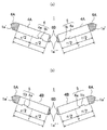
- (A), (b) is the top view which showed other embodiment of the slot opened in a rotor, and the magnet inserted in this.
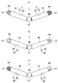
- (A), (b), (c) is the top view which showed other embodiment of the slot opened in a rotor, and the magnet inserted in this.
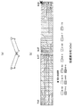
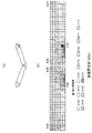
- (a) is a figure which shows the comparative example model of a magnet and a slot
- (b) is a contour figure of the demagnetizing field by the magnetic field analysis. is there.
- two magnets are arranged in a substantially V shape to form one magnetic pole, but one magnet is arranged to be orthogonal to the radial direction of the rotor to form one magnetic pole. It may be a form to do.
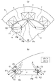
- FIG. 1 is a schematic diagram simulating a part of a rotor and a stator constituting an IPM motor of the present invention.
- a stator 2 made of a laminate of electromagnetic steel sheets or the like is composed of an annular yoke and teeth projecting radially inward from the yoke, and a coil 3 is formed around the teeth via an insulating bobbin (not shown).
- a rotor 1 made of a laminated body of electromagnetic steel plates or the like is similarly arranged so as to be rotatable around a shaft SF to constitute an IPM motor.
- each permanent magnet 4 is accommodated in the corresponding slot 1a so that the two permanent magnets 4 and 4 are arranged in a substantially V shape in plan view to form one magnetic pole.
- a protrusion 1b is provided on the slot surface on the rotor core center side of the slot 1a, and when the permanent magnet 4 is housed in the slot 1a, the protrusion 1b is located at a position corresponding to the protrusion 1b.
- the recessed groove 4a to be fitted is engraved, and the permanent magnet 4 is accommodated in the slot 1a by inserting the permanent magnet 4 into the slot 1a while fitting the recessed groove 4a to the protrusion 1b.
- groove 4a and the protrusion 1b engaging each other is formed, and the permanent magnet 4 is formed by this engaging part 5. Positioning and fixing within the slot 1a is guaranteed.
- low permeability resin is placed in the magnet side slots 1 a ′ and 1 a ′′ which are spaces between the V-shaped outer side, the V-shaped inner side surface and the slot surface. Filled flux barriers 6A and 6B are formed.
- These flux barriers 6A and 6B have different planar shapes from each other for the purpose of reducing leakage magnetic flux from the side and preventing magnetic saturation from occurring on the side of the permanent magnet.
- 6B also include a region having the same thickness s1 as the permanent magnet 4 in a part thereof, more specifically, a region in contact with the permanent magnet 4.
- the flux barrier on the side of the permanent magnet PM shown in FIG. 8b has the same thickness as the thickness t1 of the permanent magnet PM. There was no region, and the magnetic flux J from the stator was concentrated in the corner region on the stator side of the permanent magnet PM.
- the magnetic side slots 1 a ′ and 1 a ′′ are provided with regions having the same thickness s 1 as the permanent magnet 4, so that the magnetic flux entering from the stator Does not reach the rotor core in the shortest time even if it passes through the flux barriers 6A and 6B, and as a result, the concentration of the magnetic flux trying to pass through the corner regions of the flux barriers 6A and 6B and the permanent magnet 4 is eliminated. .
- the permanent magnet 4 is a coercive force distribution magnet, it is not necessary to make the corner region on the stator side an excessively high coercive force region, and the amount of dysprosium or the like used compared to the coercive force distribution magnet of the conventional structure Can be reduced.
- the permanent magnet 4 is composed of any one of a rare earth magnet, a ferrite magnet, and an alnico magnet.
- a rare earth magnet a three-component neodymium magnet obtained by adding iron and boron to neodymium, a two-component system composed of samarium and cobalt. It consists of any one of samarium cobalt magnets, samarium iron nitrogen magnets, praseodymium magnets and the like.
- the flux barrier may be formed of air in addition to the resin. Even in the case of a flux barrier made of air, the permanent magnet 4 is positioned and fixed to the slot 1a via the engaging portion 5, so that no positional deviation or dropout in the slot can occur.
- FIGS. 2 and 3 are plan views showing another embodiment of a slot opened in the rotor and a magnet inserted into the slot.
- both of the two permanent magnets 4A are provided with a concave groove 4a on the inner side of the letter V from the center position thereof, and the projection 1b of the slot is engaged with the concave groove 4a.
- the part 5 is formed.
- both the two permanent magnets 4B are provided with a concave groove 4a on the V-shaped outer side from the center position thereof, and the projection 1b of the slot is engaged with the concave groove 4a.
- the engaging portion 5 is formed.
- both the two permanent magnets 4C are provided with a concave groove 4a on the stator side of the permanent magnet 4C, and the projection 1b of the slot is engaged with the concave groove 4a so that the engaging portion 5 is engaged. Is formed.
- FIG. 3B includes a concave groove 4a ′ having a substantially semi-elliptical shape in plan view and a smooth curve at the center positions of the two permanent magnets 4D, and is complementary to the concave groove 4a.
- An engaging portion 5A is formed by engaging the projection 1b ′ of the target-shaped slot.
- the two permanent magnets 4E are each provided with a projection 4b having a rectangular shape in plan view at the center position thereof, and the groove 4c of the slot is engaged with the projection 4b, and the engaging portion 5B is formed.
- a concave groove or a projection may be provided in any of the permanent magnet 4 and the slot 1a, and a concave groove or a projection may be provided on any of the stator side surface or the rotor core central side surface.
- the position of the groove or the like may be any of the center position of the permanent magnet 4, the outer position of the V-shape, and the inner position.
- the present inventors modeled a V-shaped permanent magnet model (comparative example) of a conventional structure and a V-shaped permanent magnet model (Examples 1, 2, and 3) according to the present invention in a computer, The magnetic field analysis is performed to determine the demagnetizing field in each permanent magnet model and to create a contour diagram thereof, and the maximum demagnetizing field value in each permanent magnet model and the demagnetizing field values of the comparative examples of Examples 1, 2, and 3 are compared. The amount of decrease was determined.
- the comparative example model has an edge on the side of the permanent magnet as shown in FIG. 8b, and the slot and the permanent magnet are not engaged at the engaging portion.
- Each of the models of Examples 1, 2, and 3 includes a region in which the flux barriers on both sides of the permanent magnet have the same thickness as that of the permanent magnet, and the permanent magnet and the slot are interposed via the engaging portion on the rotor core center side. Is engaged.
- the engaging portion is located outside the V shape from the central position of the permanent magnet
- the engaging portion is in the central position of the permanent magnet
- the engaging portion is provided. It is located inside the letter V from the center position of the permanent magnet.
- each figure 4 shows the permanent magnet models of the comparative example and Examples 1, 2, and 3 in each figure a
- each figure b shows the demagnetizing field contour diagram that is the analysis result.
- the x-marked portions in FIG. 5B are the portions that give the maximum demagnetizing field.
- the thickness in plan view is 0.5 mm and the length is 2.2 mm.
- Table 1 below shows the value of the maximum demagnetizing field of the comparative example and the first, second, and third examples and the amount of demagnetizing field decrease for the comparative example of the first, second, and third examples.
- the demagnetizing field is large in both corner areas on the stator side of the permanent magnet, and the maximum demagnetizing field is 8.62 kOe particularly in the corner area outside the V shape.
- Example 1 the value of the maximum demagnetizing field can be reduced to 7.12 kOe, and in Example 3 in which the engaging portion is inside the V shape of the permanent magnet, it can be further reduced to 7.10 kOe. Has been.
- the demagnetizing field tends to concentrate on the place where the engaging portion is formed. This is because the distance from the side surface on the stator side to the groove becomes shorter than the thickness of the other part of the permanent magnet because the groove is provided in the permanent magnet, and the magnetic flux from the stator is easily concentrated. As a result, the demagnetizing field is increased.
- the engaging portions formed in the slots of the permanent magnet and the rotor not only reduce the demagnetizing field but also change the demagnetizing field distribution in the permanent magnet.
- a permanent magnet having a distributed coercive force By producing a permanent magnet having a distributed coercive force, a permanent magnet having a desired coercive force performance can be obtained while reducing the amount of dysprosium used as much as possible.
Landscapes
- Engineering & Computer Science (AREA)
- Power Engineering (AREA)
- Permanent Field Magnets Of Synchronous Machinery (AREA)
Abstract
Description
本発明者等は、従来構造のVの字配置の永久磁石モデル(比較例)、本発明にかかるVの字配置の永久磁石モデル(実施例1,2,3)をコンピュータ内でモデル化し、磁場解析をおこなって各永久磁石モデル内における反磁界を求めてそのコンター図を作成するとともに、各永久磁石モデルにおける最大反磁界の値と、実施例1,2,3の比較例に対する反磁界の減少量を求めた。

Claims (5)
- モータを構成するロータのロータコアに開設されたスロットのうち、ロータコア中央側のスロット面もしくはこのスロット面に対向するステータ側のスロット面の少なくともいずれか一方に突起もしくは凹溝が形成され、
前記スロットに収容される磁石に前記スロット面の突起もしくは凹溝と係合する磁石の凹溝もしくは突起が形成されており、
スロットと磁石がそれぞれの凹溝と突起を係合させて係合部を形成し、この係合部にて磁石がロータ内で位置決め固定され、
磁石の側方面とスロット面の間に該磁石の厚みを備えたフラックスバリアが形成されているロータ。 - 2つの前記スロットが略Vの字配置で離間してロータコアに開設され、双方のスロットに前記磁石が位置決め固定され、フラックスバリアが形成されて1つの磁極を成している請求項1に記載のロータ。
- 略Vの字配置の2つの前記磁石はともに、それぞれの前記係合部が該磁石の中心位置よりも他方の磁石側に形成されている請求項2に記載のロータ。
- 前記フラックスバリアが樹脂もしくは空気のいずれか一方からなる請求項1~3のいずれかに記載のロータ。
- 請求項1~4のいずれかに記載のロータとステータからなるIPMモータ。
Priority Applications (5)
| Application Number | Priority Date | Filing Date | Title |
|---|---|---|---|
| US13/809,910 US8729763B2 (en) | 2010-07-23 | 2010-07-23 | Rotor and IPM motor |
| CN201080068207.2A CN103026585B (zh) | 2010-07-23 | 2010-07-23 | 转子和ipm马达 |
| PCT/JP2010/062457 WO2012011191A1 (ja) | 2010-07-23 | 2010-07-23 | ロータとipmモータ |
| JP2012525287A JP5382222B2 (ja) | 2010-07-23 | 2010-07-23 | ロータとipmモータ |
| DE112010005756T DE112010005756T5 (de) | 2010-07-23 | 2010-07-23 | Rotor und IPM-Motor |
Applications Claiming Priority (1)
| Application Number | Priority Date | Filing Date | Title |
|---|---|---|---|
| PCT/JP2010/062457 WO2012011191A1 (ja) | 2010-07-23 | 2010-07-23 | ロータとipmモータ |
Publications (1)
| Publication Number | Publication Date |
|---|---|
| WO2012011191A1 true WO2012011191A1 (ja) | 2012-01-26 |
Family
ID=45496631
Family Applications (1)
| Application Number | Title | Priority Date | Filing Date |
|---|---|---|---|
| PCT/JP2010/062457 WO2012011191A1 (ja) | 2010-07-23 | 2010-07-23 | ロータとipmモータ |
Country Status (5)
| Country | Link |
|---|---|
| US (1) | US8729763B2 (ja) |
| JP (1) | JP5382222B2 (ja) |
| CN (1) | CN103026585B (ja) |
| DE (1) | DE112010005756T5 (ja) |
| WO (1) | WO2012011191A1 (ja) |
Cited By (10)
| Publication number | Priority date | Publication date | Assignee | Title |
|---|---|---|---|---|
| CN102684342A (zh) * | 2012-06-04 | 2012-09-19 | 浙江西子富沃德电机有限公司 | 内置式永磁电机转子和采用该转子的永磁电机 |
| WO2014034344A1 (ja) * | 2012-08-31 | 2014-03-06 | 日立オートモティブシステムズ株式会社 | 回転電機 |
| CN103872824A (zh) * | 2012-12-18 | 2014-06-18 | 发那科株式会社 | 磁铁埋入式同步电动机的转子以及磁铁埋入式同步电动机 |
| JP2014155242A (ja) * | 2013-02-05 | 2014-08-25 | Toyota Motor Corp | 回転電機の磁石埋め込み型ロータおよび回転電機 |
| US20150171680A1 (en) * | 2012-06-14 | 2015-06-18 | Daikin Industries, Ltd. | Interior permanent magnet rotary electric machine |
| US9331531B2 (en) | 2012-10-17 | 2016-05-03 | Eocycle Technologies Inc. | Method of manufacturing a transverse flux electrical machine rotor |
| US9419486B2 (en) | 2012-09-24 | 2016-08-16 | Eocycle Technologies Inc. | Housing less transverse flux electrical machine |
| US9722479B2 (en) | 2012-08-03 | 2017-08-01 | Eocycle Technologies Inc. | Wind turbine comprising a transverse flux electrical machine |
| JP2017158282A (ja) * | 2016-03-01 | 2017-09-07 | 本田技研工業株式会社 | 回転電機 |
| JP2019208306A (ja) * | 2018-05-28 | 2019-12-05 | Tdk株式会社 | 永久磁石及びモータ |
Families Citing this family (30)
| Publication number | Priority date | Publication date | Assignee | Title |
|---|---|---|---|---|
| US9577483B2 (en) * | 2012-04-06 | 2017-02-21 | Mitsubishi Electric Corporation | Rotor for a permanent-magnet embedded motor having permanent magnets fitted into a plurality of magnet insertion holes formed in a circumferential direction |
| WO2014045445A1 (ja) * | 2012-09-24 | 2014-03-27 | 三菱電機株式会社 | 永久磁石埋込型電動機 |
| JP5910464B2 (ja) * | 2012-11-02 | 2016-04-27 | 株式会社デンソー | 回転電機のロータ |
| JP6210711B2 (ja) * | 2013-04-23 | 2017-10-11 | 株式会社日立産機システム | 永久磁石電動機 |
| JP2015089178A (ja) * | 2013-10-29 | 2015-05-07 | 三菱電機株式会社 | 永久磁石埋込型回転電機 |
| TWI508414B (zh) * | 2013-11-12 | 2015-11-11 | Hon Hai Prec Ind Co Ltd | 轉子及採用該轉子之馬達 |
| DE102014214469A1 (de) | 2014-07-24 | 2016-01-28 | Siemens Aktiengesellschaft | Rotor für eine elektrische Maschine |
| JP6449110B2 (ja) * | 2015-06-15 | 2019-01-09 | マブチモーター株式会社 | ロータ、モータおよびロータの製造方法 |
| DE112016004565T5 (de) * | 2015-10-06 | 2018-07-05 | Mitsubishi Electric Corporation | Elektrische rotationsmaschine |
| US10211690B2 (en) * | 2016-04-28 | 2019-02-19 | Faraday & Future Inc. | IPM machine with specialized rotor for automotive electric vehicles |
| CN106059145A (zh) * | 2016-07-15 | 2016-10-26 | 珠海凌达压缩机有限公司 | 电机转子及变频电机 |
| CN106130224A (zh) * | 2016-08-18 | 2016-11-16 | 南京高传电机制造有限公司 | 永磁调速汽车驱动电机 |
| US10797544B2 (en) * | 2016-12-15 | 2020-10-06 | Ford Global Technologies, Llc | Rotor for shaping airgap flux density |
| US10749391B2 (en) * | 2017-03-06 | 2020-08-18 | Ford Global Technologies, Llc | Electric machine rotor |
| FR3067880B1 (fr) * | 2017-06-15 | 2020-07-17 | Moteurs Leroy-Somer | Machine electrique tournante |
| CN113991958A (zh) | 2017-07-21 | 2022-01-28 | 株式会社电装 | 旋转电机 |
| TWM576750U (zh) | 2017-07-25 | 2019-04-11 | 美商米沃奇電子工具公司 | 電氣組合物、電動化裝置系統、電池組、電馬達、馬達總成及電馬達總成 |
| JP6879140B2 (ja) * | 2017-09-15 | 2021-06-02 | トヨタ自動車株式会社 | 回転電機 |
| CN111512519B (zh) | 2017-12-28 | 2022-10-11 | 株式会社电装 | 旋转电机 |
| CN111557069A (zh) | 2017-12-28 | 2020-08-18 | 株式会社电装 | 旋转电机 |
| DE102018210967A1 (de) * | 2018-07-04 | 2020-01-09 | Brose Fahrzeugteile GmbH & Co. Kommanditgesellschaft, Würzburg | Rotor |
| JP6989458B2 (ja) * | 2018-08-03 | 2022-01-05 | 株式会社東芝 | 回転電機の回転子 |
| EP3917708A4 (en) | 2019-02-18 | 2022-11-30 | Milwaukee Electric Tool Corporation | IMPACT TOOL |
| JP2020156242A (ja) * | 2019-03-20 | 2020-09-24 | 株式会社デンソー | 回転電機 |
| KR20210077225A (ko) * | 2019-12-17 | 2021-06-25 | 현대자동차주식회사 | 구동 모터에 적용되는 회전자 |
| CN111161933A (zh) * | 2019-12-23 | 2020-05-15 | 湖南航天磁电有限责任公司 | 一种高矫顽力低温度系数烧结钐钴永磁体的制备方法 |
| DE112020006839T5 (de) | 2020-03-05 | 2022-12-15 | Denso Corporation | Rotierende elektrische Maschinen |
| JP6983274B2 (ja) * | 2020-04-23 | 2021-12-17 | 三菱電機株式会社 | 回転電機の回転子及びその製造方法 |
| CN112491177B (zh) * | 2020-12-10 | 2022-04-22 | 华中科技大学 | 一种抗去磁转子及mw级永磁同步风力发电机 |
| DE102022206623A1 (de) | 2022-06-29 | 2024-01-04 | Valeo Eautomotive Germany Gmbh | Verbesserte Fixierung von Rotormagneten in einem Rotor einer elektrischen Maschine |
Citations (4)
| Publication number | Priority date | Publication date | Assignee | Title |
|---|---|---|---|---|
| JP2004104962A (ja) * | 2002-09-12 | 2004-04-02 | Toshiba Industrial Products Manufacturing Corp | 永久磁石式リラクタンス型回転電機 |
| JP2007097290A (ja) * | 2005-09-28 | 2007-04-12 | Toshiba Industrial Products Manufacturing Corp | 永久磁石型リラクタンス回転電機 |
| JP2007336671A (ja) * | 2006-06-14 | 2007-12-27 | Toshiba Mitsubishi-Electric Industrial System Corp | 永久磁石回転電機の回転子 |
| JP2008283823A (ja) * | 2007-05-11 | 2008-11-20 | Toyota Motor Corp | 回転電機のロータおよびその製造方法 |
Family Cites Families (15)
| Publication number | Priority date | Publication date | Assignee | Title |
|---|---|---|---|---|
| JP2000050542A (ja) | 1998-07-23 | 2000-02-18 | Okuma Corp | リラクタンスモータ |
| JP3659055B2 (ja) | 1999-03-26 | 2005-06-15 | 日産自動車株式会社 | 電動機のロータ |
| JP3748387B2 (ja) * | 2001-04-05 | 2006-02-22 | 株式会社日立製作所 | 永久磁石式回転電機及びそれを用いた発電システムと駆動システム |
| JP2004260920A (ja) * | 2003-02-26 | 2004-09-16 | Toyota Motor Corp | 回転子およびそれを含む電動機 |
| JP2005341655A (ja) * | 2004-05-24 | 2005-12-08 | Denso Corp | 磁石埋め込み式回転電機のロータ |
| JP2006050739A (ja) * | 2004-08-03 | 2006-02-16 | Denso Corp | 埋め込み磁石型同期モータの磁気騒音低減方法 |
| US7504754B2 (en) * | 2005-10-31 | 2009-03-17 | Caterpillar Inc. | Rotor having multiple permanent-magnet pieces in a cavity |
| US7436096B2 (en) * | 2005-10-31 | 2008-10-14 | Caterpillar Inc. | Rotor having permanent magnets and axialy-extending channels |
| JP2006109700A (ja) * | 2006-01-10 | 2006-04-20 | Aichi Elec Co | インテリアル・パーマネントマグネット・モータ |
| CN1835340A (zh) | 2006-03-30 | 2006-09-20 | 上海大学 | 永磁电机“v”型内置式转子 |
| JP5212680B2 (ja) | 2006-12-12 | 2013-06-19 | 日本電産株式会社 | モータ |
| JP4952786B2 (ja) * | 2007-03-15 | 2012-06-13 | ダイキン工業株式会社 | 界磁子 |
| US20090140593A1 (en) * | 2007-11-30 | 2009-06-04 | Gm Global Technology Operations, Inc. | Methods and apparatus for a permanent magnet machine with added rotor slots |
| US7902710B2 (en) * | 2008-10-01 | 2011-03-08 | Caterpillar Inc. | Electric machine |
| US8174158B2 (en) * | 2009-02-20 | 2012-05-08 | GM Global Technology Operations LLC | Methods and apparatus for a permanent magnet machine with asymmetrical rotor magnets |
-
2010
- 2010-07-23 CN CN201080068207.2A patent/CN103026585B/zh active Active
- 2010-07-23 DE DE112010005756T patent/DE112010005756T5/de not_active Withdrawn
- 2010-07-23 US US13/809,910 patent/US8729763B2/en active Active
- 2010-07-23 WO PCT/JP2010/062457 patent/WO2012011191A1/ja active Application Filing
- 2010-07-23 JP JP2012525287A patent/JP5382222B2/ja active Active
Patent Citations (4)
| Publication number | Priority date | Publication date | Assignee | Title |
|---|---|---|---|---|
| JP2004104962A (ja) * | 2002-09-12 | 2004-04-02 | Toshiba Industrial Products Manufacturing Corp | 永久磁石式リラクタンス型回転電機 |
| JP2007097290A (ja) * | 2005-09-28 | 2007-04-12 | Toshiba Industrial Products Manufacturing Corp | 永久磁石型リラクタンス回転電機 |
| JP2007336671A (ja) * | 2006-06-14 | 2007-12-27 | Toshiba Mitsubishi-Electric Industrial System Corp | 永久磁石回転電機の回転子 |
| JP2008283823A (ja) * | 2007-05-11 | 2008-11-20 | Toyota Motor Corp | 回転電機のロータおよびその製造方法 |
Cited By (19)
| Publication number | Priority date | Publication date | Assignee | Title |
|---|---|---|---|---|
| CN102684342A (zh) * | 2012-06-04 | 2012-09-19 | 浙江西子富沃德电机有限公司 | 内置式永磁电机转子和采用该转子的永磁电机 |
| US20150171680A1 (en) * | 2012-06-14 | 2015-06-18 | Daikin Industries, Ltd. | Interior permanent magnet rotary electric machine |
| US9755492B2 (en) | 2012-08-03 | 2017-09-05 | Eocycle Technologies Inc. | Rotatable transverse flux electrical machine |
| US9722479B2 (en) | 2012-08-03 | 2017-08-01 | Eocycle Technologies Inc. | Wind turbine comprising a transverse flux electrical machine |
| WO2014034344A1 (ja) * | 2012-08-31 | 2014-03-06 | 日立オートモティブシステムズ株式会社 | 回転電機 |
| JP2014050208A (ja) * | 2012-08-31 | 2014-03-17 | Hitachi Automotive Systems Ltd | 回転電機 |
| US20150236555A1 (en) * | 2012-08-31 | 2015-08-20 | Hitachi Automotive Systems, Ltd. | Rotating Electric Machine |
| US9680341B2 (en) | 2012-08-31 | 2017-06-13 | Hitachi Automotive Systems, Ltd. | Rotating electric machine including rotor core with slots having protrusions |
| US9419486B2 (en) | 2012-09-24 | 2016-08-16 | Eocycle Technologies Inc. | Housing less transverse flux electrical machine |
| US9559560B2 (en) | 2012-09-24 | 2017-01-31 | Eocycle Technologies Inc. | Transverse flux electrical machine stator phases assembly |
| US9559559B2 (en) | 2012-09-24 | 2017-01-31 | Eocycle Technologies Inc. | Transverse flux electrical machine stator with stator skew and assembly thereof |
| US9559558B2 (en) | 2012-09-24 | 2017-01-31 | Eocycle Technologies Inc. | Modular transverse flux electrical machine assembly |
| US9331531B2 (en) | 2012-10-17 | 2016-05-03 | Eocycle Technologies Inc. | Method of manufacturing a transverse flux electrical machine rotor |
| US9876401B2 (en) | 2012-10-17 | 2018-01-23 | Eocycle Technologies Inc. | Transverse flux electrical machine rotor |
| CN103872824A (zh) * | 2012-12-18 | 2014-06-18 | 发那科株式会社 | 磁铁埋入式同步电动机的转子以及磁铁埋入式同步电动机 |
| JP2014155242A (ja) * | 2013-02-05 | 2014-08-25 | Toyota Motor Corp | 回転電機の磁石埋め込み型ロータおよび回転電機 |
| JP2017158282A (ja) * | 2016-03-01 | 2017-09-07 | 本田技研工業株式会社 | 回転電機 |
| JP2019208306A (ja) * | 2018-05-28 | 2019-12-05 | Tdk株式会社 | 永久磁石及びモータ |
| JP7263698B2 (ja) | 2018-05-28 | 2023-04-25 | Tdk株式会社 | 永久磁石及びモータ |
Also Published As
| Publication number | Publication date |
|---|---|
| US8729763B2 (en) | 2014-05-20 |
| JP5382222B2 (ja) | 2014-01-08 |
| DE112010005756T5 (de) | 2013-07-04 |
| CN103026585B (zh) | 2014-07-09 |
| CN103026585A (zh) | 2013-04-03 |
| JPWO2012011191A1 (ja) | 2013-09-09 |
| US20130113328A1 (en) | 2013-05-09 |
Similar Documents
| Publication | Publication Date | Title |
|---|---|---|
| JP5382222B2 (ja) | ロータとipmモータ | |
| JP5305887B2 (ja) | 永久磁石式回転電機 | |
| JP5709907B2 (ja) | 車両用永久磁石埋込型回転電機 | |
| JP5359895B2 (ja) | Ipmモータ用ロータとipmモータ | |
| JP5238231B2 (ja) | 回転電機の回転子 | |
| JP5891089B2 (ja) | 永久磁石同期機 | |
| JP5542423B2 (ja) | 回転電機の回転子、および回転電機 | |
| KR101575353B1 (ko) | 자석 매립형 로터 | |
| EP2043231A1 (en) | Field element | |
| US20120299429A1 (en) | Rotor and motor | |
| JP5963935B2 (ja) | 永久磁石埋込型電動機 | |
| JP2010119190A (ja) | 磁石埋め込み型モータ用ロータと磁石埋め込み型モータ | |
| CN103840585A (zh) | 旋转电机的转子 | |
| JP2011035997A (ja) | Ipmモータ用ロータとipmモータ | |
| JP2009273240A (ja) | Ipmモータ用ロータとその製造方法 | |
| JP2011239607A (ja) | 内磁形ロータおよびその磁石固定方法 | |
| US20220294289A1 (en) | Rotor and motor | |
| JP5444756B2 (ja) | Ipmモータ用ロータとipmモータ | |
| KR101367222B1 (ko) | 영구자석 동기 모터 | |
| JP2017147810A (ja) | 埋込磁石型モータ | |
| JP5750995B2 (ja) | 同期電動機 | |
| JP2014090575A (ja) | Ipmモータ用ロータ | |
| US11682936B2 (en) | Motor | |
| JP7020354B2 (ja) | 永久磁石式モータ | |
| JP2017135923A (ja) | モータ用ロータ |
Legal Events
| Date | Code | Title | Description |
|---|---|---|---|
| WWE | Wipo information: entry into national phase |
Ref document number: 201080068207.2 Country of ref document: CN |
|
| 121 | Ep: the epo has been informed by wipo that ep was designated in this application |
Ref document number: 10855028 Country of ref document: EP Kind code of ref document: A1 |
|
| WWE | Wipo information: entry into national phase |
Ref document number: 2012525287 Country of ref document: JP |
|
| WWE | Wipo information: entry into national phase |
Ref document number: 13809910 Country of ref document: US |
|
| WWE | Wipo information: entry into national phase |
Ref document number: 1120100057567 Country of ref document: DE Ref document number: 112010005756 Country of ref document: DE |
|
| 122 | Ep: pct application non-entry in european phase |
Ref document number: 10855028 Country of ref document: EP Kind code of ref document: A1 |