WO2012008587A1 - 赤外線反射基板および合わせガラス - Google Patents
赤外線反射基板および合わせガラス Download PDFInfo
- Publication number
- WO2012008587A1 WO2012008587A1 PCT/JP2011/066257 JP2011066257W WO2012008587A1 WO 2012008587 A1 WO2012008587 A1 WO 2012008587A1 JP 2011066257 W JP2011066257 W JP 2011066257W WO 2012008587 A1 WO2012008587 A1 WO 2012008587A1
- Authority
- WO
- WIPO (PCT)
- Prior art keywords
- substrate
- refractive index
- infrared
- dielectric film
- laminated
- Prior art date
- Legal status (The legal status is an assumption and is not a legal conclusion. Google has not performed a legal analysis and makes no representation as to the accuracy of the status listed.)
- Ceased
Links
Images




Classifications
-
- B—PERFORMING OPERATIONS; TRANSPORTING
- B32—LAYERED PRODUCTS
- B32B—LAYERED PRODUCTS, i.e. PRODUCTS BUILT-UP OF STRATA OF FLAT OR NON-FLAT, e.g. CELLULAR OR HONEYCOMB, FORM
- B32B17/00—Layered products essentially comprising sheet glass, or glass, slag, or like fibres
- B32B17/06—Layered products essentially comprising sheet glass, or glass, slag, or like fibres comprising glass as the main or only constituent of a layer, next to another layer of a specific material
- B32B17/10—Layered products essentially comprising sheet glass, or glass, slag, or like fibres comprising glass as the main or only constituent of a layer, next to another layer of a specific material of synthetic resin
- B32B17/10005—Layered products essentially comprising sheet glass, or glass, slag, or like fibres comprising glass as the main or only constituent of a layer, next to another layer of a specific material of synthetic resin laminated safety glass or glazing
- B32B17/10009—Layered products essentially comprising sheet glass, or glass, slag, or like fibres comprising glass as the main or only constituent of a layer, next to another layer of a specific material of synthetic resin laminated safety glass or glazing characterized by the number, the constitution or treatment of glass sheets
- B32B17/10036—Layered products essentially comprising sheet glass, or glass, slag, or like fibres comprising glass as the main or only constituent of a layer, next to another layer of a specific material of synthetic resin laminated safety glass or glazing characterized by the number, the constitution or treatment of glass sheets comprising two outer glass sheets
-
- G—PHYSICS
- G02—OPTICS
- G02B—OPTICAL ELEMENTS, SYSTEMS OR APPARATUS
- G02B5/00—Optical elements other than lenses
- G02B5/20—Filters
- G02B5/208—Filters for use with infrared or ultraviolet radiation, e.g. for separating visible light from infrared and/or ultraviolet radiation
-
- B—PERFORMING OPERATIONS; TRANSPORTING
- B32—LAYERED PRODUCTS
- B32B—LAYERED PRODUCTS, i.e. PRODUCTS BUILT-UP OF STRATA OF FLAT OR NON-FLAT, e.g. CELLULAR OR HONEYCOMB, FORM
- B32B17/00—Layered products essentially comprising sheet glass, or glass, slag, or like fibres
- B32B17/06—Layered products essentially comprising sheet glass, or glass, slag, or like fibres comprising glass as the main or only constituent of a layer, next to another layer of a specific material
- B32B17/10—Layered products essentially comprising sheet glass, or glass, slag, or like fibres comprising glass as the main or only constituent of a layer, next to another layer of a specific material of synthetic resin
- B32B17/10005—Layered products essentially comprising sheet glass, or glass, slag, or like fibres comprising glass as the main or only constituent of a layer, next to another layer of a specific material of synthetic resin laminated safety glass or glazing
- B32B17/10009—Layered products essentially comprising sheet glass, or glass, slag, or like fibres comprising glass as the main or only constituent of a layer, next to another layer of a specific material of synthetic resin laminated safety glass or glazing characterized by the number, the constitution or treatment of glass sheets
- B32B17/10036—Layered products essentially comprising sheet glass, or glass, slag, or like fibres comprising glass as the main or only constituent of a layer, next to another layer of a specific material of synthetic resin laminated safety glass or glazing characterized by the number, the constitution or treatment of glass sheets comprising two outer glass sheets
- B32B17/10045—Layered products essentially comprising sheet glass, or glass, slag, or like fibres comprising glass as the main or only constituent of a layer, next to another layer of a specific material of synthetic resin laminated safety glass or glazing characterized by the number, the constitution or treatment of glass sheets comprising two outer glass sheets with at least one intermediate layer consisting of a glass sheet
-
- B—PERFORMING OPERATIONS; TRANSPORTING
- B32—LAYERED PRODUCTS
- B32B—LAYERED PRODUCTS, i.e. PRODUCTS BUILT-UP OF STRATA OF FLAT OR NON-FLAT, e.g. CELLULAR OR HONEYCOMB, FORM
- B32B17/00—Layered products essentially comprising sheet glass, or glass, slag, or like fibres
- B32B17/06—Layered products essentially comprising sheet glass, or glass, slag, or like fibres comprising glass as the main or only constituent of a layer, next to another layer of a specific material
- B32B17/10—Layered products essentially comprising sheet glass, or glass, slag, or like fibres comprising glass as the main or only constituent of a layer, next to another layer of a specific material of synthetic resin
- B32B17/10005—Layered products essentially comprising sheet glass, or glass, slag, or like fibres comprising glass as the main or only constituent of a layer, next to another layer of a specific material of synthetic resin laminated safety glass or glazing
- B32B17/10009—Layered products essentially comprising sheet glass, or glass, slag, or like fibres comprising glass as the main or only constituent of a layer, next to another layer of a specific material of synthetic resin laminated safety glass or glazing characterized by the number, the constitution or treatment of glass sheets
- B32B17/10082—Properties of the bulk of a glass sheet
- B32B17/1011—Properties of the bulk of a glass sheet having predetermined tint or excitation purity
-
- B—PERFORMING OPERATIONS; TRANSPORTING
- B32—LAYERED PRODUCTS
- B32B—LAYERED PRODUCTS, i.e. PRODUCTS BUILT-UP OF STRATA OF FLAT OR NON-FLAT, e.g. CELLULAR OR HONEYCOMB, FORM
- B32B17/00—Layered products essentially comprising sheet glass, or glass, slag, or like fibres
- B32B17/06—Layered products essentially comprising sheet glass, or glass, slag, or like fibres comprising glass as the main or only constituent of a layer, next to another layer of a specific material
- B32B17/10—Layered products essentially comprising sheet glass, or glass, slag, or like fibres comprising glass as the main or only constituent of a layer, next to another layer of a specific material of synthetic resin
- B32B17/10005—Layered products essentially comprising sheet glass, or glass, slag, or like fibres comprising glass as the main or only constituent of a layer, next to another layer of a specific material of synthetic resin laminated safety glass or glazing
- B32B17/10165—Functional features of the laminated safety glass or glazing
- B32B17/10174—Coatings of a metallic or dielectric material on a constituent layer of glass or polymer
- B32B17/10201—Dielectric coatings
-
- B—PERFORMING OPERATIONS; TRANSPORTING
- B32—LAYERED PRODUCTS
- B32B—LAYERED PRODUCTS, i.e. PRODUCTS BUILT-UP OF STRATA OF FLAT OR NON-FLAT, e.g. CELLULAR OR HONEYCOMB, FORM
- B32B17/00—Layered products essentially comprising sheet glass, or glass, slag, or like fibres
- B32B17/06—Layered products essentially comprising sheet glass, or glass, slag, or like fibres comprising glass as the main or only constituent of a layer, next to another layer of a specific material
- B32B17/10—Layered products essentially comprising sheet glass, or glass, slag, or like fibres comprising glass as the main or only constituent of a layer, next to another layer of a specific material of synthetic resin
- B32B17/10005—Layered products essentially comprising sheet glass, or glass, slag, or like fibres comprising glass as the main or only constituent of a layer, next to another layer of a specific material of synthetic resin laminated safety glass or glazing
- B32B17/1055—Layered products essentially comprising sheet glass, or glass, slag, or like fibres comprising glass as the main or only constituent of a layer, next to another layer of a specific material of synthetic resin laminated safety glass or glazing characterized by the resin layer, i.e. interlayer
- B32B17/10614—Layered products essentially comprising sheet glass, or glass, slag, or like fibres comprising glass as the main or only constituent of a layer, next to another layer of a specific material of synthetic resin laminated safety glass or glazing characterized by the resin layer, i.e. interlayer comprising particles for purposes other than dyeing
- B32B17/10633—Infrared radiation absorbing or reflecting agents
-
- C—CHEMISTRY; METALLURGY
- C03—GLASS; MINERAL OR SLAG WOOL
- C03C—CHEMICAL COMPOSITION OF GLASSES, GLAZES OR VITREOUS ENAMELS; SURFACE TREATMENT OF GLASS; SURFACE TREATMENT OF FIBRES OR FILAMENTS MADE FROM GLASS, MINERALS OR SLAGS; JOINING GLASS TO GLASS OR OTHER MATERIALS
- C03C17/00—Surface treatment of glass, not in the form of fibres or filaments, by coating
- C03C17/34—Surface treatment of glass, not in the form of fibres or filaments, by coating with at least two coatings having different compositions
- C03C17/3411—Surface treatment of glass, not in the form of fibres or filaments, by coating with at least two coatings having different compositions with at least two coatings of inorganic materials
- C03C17/3417—Surface treatment of glass, not in the form of fibres or filaments, by coating with at least two coatings having different compositions with at least two coatings of inorganic materials all coatings being oxide coatings
-
- C—CHEMISTRY; METALLURGY
- C03—GLASS; MINERAL OR SLAG WOOL
- C03C—CHEMICAL COMPOSITION OF GLASSES, GLAZES OR VITREOUS ENAMELS; SURFACE TREATMENT OF GLASS; SURFACE TREATMENT OF FIBRES OR FILAMENTS MADE FROM GLASS, MINERALS OR SLAGS; JOINING GLASS TO GLASS OR OTHER MATERIALS
- C03C17/00—Surface treatment of glass, not in the form of fibres or filaments, by coating
- C03C17/34—Surface treatment of glass, not in the form of fibres or filaments, by coating with at least two coatings having different compositions
- C03C17/3411—Surface treatment of glass, not in the form of fibres or filaments, by coating with at least two coatings having different compositions with at least two coatings of inorganic materials
- C03C17/3429—Surface treatment of glass, not in the form of fibres or filaments, by coating with at least two coatings having different compositions with at least two coatings of inorganic materials at least one of the coatings being a non-oxide coating
- C03C17/3447—Surface treatment of glass, not in the form of fibres or filaments, by coating with at least two coatings having different compositions with at least two coatings of inorganic materials at least one of the coatings being a non-oxide coating comprising a halide
- C03C17/3452—Surface treatment of glass, not in the form of fibres or filaments, by coating with at least two coatings having different compositions with at least two coatings of inorganic materials at least one of the coatings being a non-oxide coating comprising a halide comprising a fluoride
-
- G—PHYSICS
- G02—OPTICS
- G02B—OPTICAL ELEMENTS, SYSTEMS OR APPARATUS
- G02B5/00—Optical elements other than lenses
- G02B5/20—Filters
- G02B5/28—Interference filters
- G02B5/281—Interference filters designed for the infrared light
- G02B5/282—Interference filters designed for the infrared light reflecting for infrared and transparent for visible light, e.g. heat reflectors, laser protection
-
- B—PERFORMING OPERATIONS; TRANSPORTING
- B32—LAYERED PRODUCTS
- B32B—LAYERED PRODUCTS, i.e. PRODUCTS BUILT-UP OF STRATA OF FLAT OR NON-FLAT, e.g. CELLULAR OR HONEYCOMB, FORM
- B32B2307/00—Properties of the layers or laminate
- B32B2307/40—Properties of the layers or laminate having particular optical properties
- B32B2307/412—Transparent
-
- B—PERFORMING OPERATIONS; TRANSPORTING
- B32—LAYERED PRODUCTS
- B32B—LAYERED PRODUCTS, i.e. PRODUCTS BUILT-UP OF STRATA OF FLAT OR NON-FLAT, e.g. CELLULAR OR HONEYCOMB, FORM
- B32B2307/00—Properties of the layers or laminate
- B32B2307/40—Properties of the layers or laminate having particular optical properties
- B32B2307/416—Reflective
-
- B—PERFORMING OPERATIONS; TRANSPORTING
- B32—LAYERED PRODUCTS
- B32B—LAYERED PRODUCTS, i.e. PRODUCTS BUILT-UP OF STRATA OF FLAT OR NON-FLAT, e.g. CELLULAR OR HONEYCOMB, FORM
- B32B2605/00—Vehicles
- B32B2605/006—Transparent parts other than made from inorganic glass, e.g. polycarbonate glazings
-
- C—CHEMISTRY; METALLURGY
- C03—GLASS; MINERAL OR SLAG WOOL
- C03C—CHEMICAL COMPOSITION OF GLASSES, GLAZES OR VITREOUS ENAMELS; SURFACE TREATMENT OF GLASS; SURFACE TREATMENT OF FIBRES OR FILAMENTS MADE FROM GLASS, MINERALS OR SLAGS; JOINING GLASS TO GLASS OR OTHER MATERIALS
- C03C2217/00—Coatings on glass
- C03C2217/70—Properties of coatings
- C03C2217/73—Anti-reflective coatings with specific characteristics
- C03C2217/734—Anti-reflective coatings with specific characteristics comprising an alternation of high and low refractive indexes
Definitions
- the present invention relates to an infrared reflective substrate and a laminated glass, and more particularly to an infrared reflective substrate from which a laminated glass having a good surface color tone can be obtained, and a laminated glass using the same.
- an infrared reflecting film that blocks transmission of infrared rays (heat rays) in sunlight between a pair of opposing glass substrates in order to suppress an increase in indoor temperature and cooling load
- the infrared reflecting film is formed on a transparent base material such as a transparent resin film to constitute an infrared reflecting substrate.
- an infrared reflecting film for example, an oxide film and a metal film alternately laminated, and a high refractive index dielectric film and a low refractive index dielectric film alternately laminated are known, for example. .
- Vehicle glass and the like are required to have high visible light transmittance and radio wave transmittance in addition to high infrared shielding ability.
- the oxide film and the metal film alternately laminated have high infrared shielding ability but are non-radioactive, and devices using radio waves such as garage openers and mobile phones are used in the car. There is a possibility that radio waves cannot be received and transmitted.
- a laminate in which a dielectric film having a high refractive index and a dielectric film having a low refractive index are alternately laminated does not have a metal film and thus has good radio wave transmission.
- the wavelength ⁇ is in the range of 900 to 1400 nm.
- An infrared ray having an n ⁇ d value of 225 to 350 nm is known (for example, see Patent Document 1). According to this, it is described that the visible light transmittance and the reflectance in the near infrared region can be increased.
- the present invention has been made in order to solve the above-described problems, and includes a substrate (hereinafter referred to as an infrared ray) having a transparent substrate having an infrared reflective film composed of a dielectric film having a high refractive index and a dielectric film having a low refractive index. It is an object of the present invention to provide a reflective substrate having a good intermediate color tone that does not have a stimulating color when used as a laminated glass. Another object of the present invention is to provide a laminated glass having a good surface color tone using such an infrared reflective substrate, and particularly to provide a laminated glass optimal as a vehicle glass.
- the infrared reflective substrate of the first aspect of the present invention is provided with a transparent substrate and one main surface of the transparent substrate, and has seven layers of high-refractive index dielectric films and low-refractive index dielectric films alternately. And an infrared reflection film laminated as described above.
- the infrared reflecting film has a high n ⁇ d / ⁇ value of 0.44 to 0.55, where d is a thickness of d [nm], and n is a refractive index when the wavelength is ⁇ [nm].
- a first laminated portion in which a dielectric film having a refractive index and a dielectric film having a low refractive index are alternately laminated continuously in five or more layers, and an n ⁇ d / ⁇ value is 0.03 to 0.12. It has a second laminated portion in which a certain high refractive index dielectric film and low refractive index dielectric film are successively laminated.
- the infrared reflective substrate according to the second aspect of the present invention is provided with a transparent substrate and five layers of a high refractive index dielectric film and a low refractive index dielectric film alternately provided on one main surface of the transparent substrate.
- Five or more layers of the first infrared reflection film laminated above and the other main surface of the transparent substrate are alternately laminated with a high refractive index dielectric film and a low refractive index dielectric film.
- a second infrared reflective film At least one of the first infrared reflection film and the second infrared reflection film has a thickness of d [nm] and a refractive index n when the wavelength is ⁇ [nm].
- the laminated glass of the first aspect of the present invention includes a pair of opposing glass substrates, an infrared reflecting substrate disposed between the pair of glass substrates, and disposed between the pair of glass substrates and the infrared reflecting substrate.
- the infrared reflective substrate is the infrared reflective substrate according to the first or second aspect of the present invention described above, and the transparent substrate is made of a resin film.
- the laminated glass of the second aspect of the present invention includes an infrared reflective substrate having an infrared reflective film only on one main surface, a glass substrate disposed facing the infrared reflective film side of the infrared reflective substrate, An adhesive layer disposed between the infrared reflective substrate and the glass substrate;
- the infrared reflective substrate is the infrared reflective substrate according to the first aspect of the present invention described above, and the transparent substrate is made of a glass plate.
- the infrared reflecting substrate of the present invention has an infrared reflecting film in which a dielectric film having a high refractive index and a dielectric film having a low refractive index are alternately laminated.
- a high refractive index dielectric film having a d / ⁇ value of 0.03 to 0.12 and a low refractive index dielectric film continuously have a second laminated portion. According to such an infrared reflective substrate, the color tone of the surface when laminated glass can be improved.
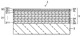
- FIG. 1 is a cross-sectional view showing an example of an infrared reflecting substrate according to the first embodiment of the present invention.
- the infrared reflective substrate 1 of the first aspect is provided on a transparent substrate 2 and one main surface of the transparent substrate 2, and a high refractive index dielectric film 3H and a low refractive index dielectric film 3L are alternately arranged.
- the infrared reflective film 3 is formed by laminating seven or more layers.
- the infrared reflecting film 3 shown in FIG. 1 has nine layers including a dielectric film 3H and a dielectric film 3L.
- This infrared reflective film 3 is a dielectric having an n ⁇ d / ⁇ value of 0.44 to 0.55, where n is the refractive index when the thickness is d [nm] and the wavelength is ⁇ [nm].
- a first laminated portion 31 in which a film 311 (consisting of a high-refractive index dielectric film 3H and a low-refractive index dielectric film 3L) is continuously laminated, and an n ⁇ d / ⁇ value is 0
- a second laminated portion 32 in which at least two dielectric films 321 (consisting of a high refractive index dielectric film 3H and a low refractive index dielectric film 3L) are successively laminated. It is characterized by having.
- continuous in “a plurality of dielectric layers composed of a dielectric film having a high refractive index and a dielectric film having a low refractive index are continuously laminated” means a dielectric film having a high refractive index. And a low-refractive-index dielectric film.
- stacking part 32 have the 1st lamination
- the part 32 may be arranged, for example, as shown in FIG. 2, the second laminated part 32 is arranged on one main surface side of the transparent substrate 2, and the first laminated part 31 is arranged on the upper layer thereof. May be.
- a layer having another function such as a protective layer may be formed on the surface of the infrared reflective film 3.
- the infrared reflective film 3 does not necessarily need to be a dielectric film 3H having a high refractive index on the transparent substrate 2 side.
- the infrared reflection film 3 selectively reflects light in the infrared region (wavelength region: 780 nm to 1000 nm) by utilizing light interference, and as shown in FIGS.
- the film 3H and the low-refractive-index dielectric film 3L are configured to be laminated by seven or more layers. When the total number of layers of the dielectric films 3H and 3L is less than 7, the visible light transmittance and the reflectance in the near-infrared region when the laminated glass is used may not be sufficient.
- the number of layers of the dielectric films 3H and 3L is not necessarily limited as long as it is 7 layers or more. However, if the number of layers exceeds 13 layers, the decrease in productivity due to an increase in the manufacturing process becomes significant. 7 to 13 layers are preferable, 7 to 11 layers are more preferable, and 7 to 9 layers are more preferable.
- the first laminated portion 31 mainly constitutes the infrared reflecting film 3 and is provided in order to obtain good optical characteristics when a laminated glass is used.
- a dielectric film 311 of a high refractive index having an n ⁇ d / ⁇ value of 0.44 to 0.55 and a dielectric film having a low refractive index are continuously formed.
- the individual dielectric films 311 can have different n ⁇ d / ⁇ values
- the dielectric films 3H and the dielectric films 3L are usually the same or substantially the same n ⁇ d / ⁇ . ⁇ value.
- n ⁇ d / ⁇ value of the dielectric film 311 When the n ⁇ d / ⁇ value of the dielectric film 311 is less than 0.44 or more than 0.55, the visible light transmittance and the reflectance in the near-infrared region when laminated glass may be insufficient.
- the n ⁇ d / ⁇ value of the dielectric film 311 is preferably 0.44 to 0.53, and more preferably 0.45 to 0.52. Further, even when the number of layers of the dielectric film 311 is less than 5, the visible light transmittance and the reflectance in the near-infrared region when the laminated glass is used may not be sufficient.
- the second laminated portion 32 is provided in order to improve the surface color tone when the laminated glass is mainly used.
- the second laminated portion 32 includes two continuous dielectric films 321 of a high refractive index dielectric film having an n ⁇ d / ⁇ value of 0.03 to 0.12 and a low refractive index dielectric film. It is a layered product.
- the n ⁇ d / ⁇ values of the individual dielectric films 321 can also be different from each other.
- n ⁇ d / ⁇ value of the dielectric film 321 When the n ⁇ d / ⁇ value of the dielectric film 321 is less than 0.03 or exceeds 0.12, the surface of the laminated glass may become an excessively reddish stimulus color.
- the n ⁇ d / ⁇ value of the dielectric film 321 is preferably 0.03 to 0.11, and more preferably 0.04 to 0.10.
- the number of layers of the dielectric film 321 is less than 2
- the surface may become an excessively reddish stimulating color.
- the number of layers of the dielectric film 321 exceeds two, when laminated glass is used, it does not affect the color tone of the surface, but in the first place, the increase in the number of layers causes a decrease in productivity. .
- the infrared reflecting film 3 when the infrared reflecting film 3 is composed of the first laminated portion 31 and the second laminated portion 32, the optical characteristics and the color tone of the laminated glass can be improved. Moreover, by setting it as such, an optical characteristic can be mainly achieved by the 1st lamination
- the n ⁇ d / ⁇ value is obtained by multiplying the product of the refractive index n and the thickness d in order to make an index independent of the wavelength ⁇ . Divided by the wavelength ⁇ . Since the n ⁇ d / ⁇ value is constant regardless of the wavelength ⁇ , in the present invention, it is sufficient that the n ⁇ d / ⁇ value has a predetermined n ⁇ d / ⁇ value at at least one wavelength ⁇ .
- a wavelength ⁇ is not particularly limited, but is usually one wavelength ⁇ within a range of 200 to 2100 nm. More typically, the wavelength ⁇ is 300 to 1200 nm.
- the n ⁇ d / ⁇ values of the dielectric films 311 and 321 can be adjusted mainly by changing the thickness d. For example, by making the thickness of the dielectric film 321 thinner than the thickness of the dielectric film 311 as a whole, the n ⁇ d / ⁇ value of the dielectric film 321 is made larger than the n ⁇ d / ⁇ value of the dielectric film 311. Can be small. Further, by reducing the thickness of the dielectric film 3H as compared with the thickness of the dielectric film 3L as a whole, the n ⁇ d / ⁇ value of the dielectric film 3H and the n ⁇ d / ⁇ value of the dielectric film 3L are reduced. Can be the same.
- the thickness of the high-refractive-index dielectric film 3H in the dielectric film 311 in the first stacked portion is slightly different depending on the refractive index, but is preferably 90 to 115 nm, more preferably 90 to 110 nm.
- the thickness of the low refractive index dielectric film 3L is preferably 150 to 195 nm, and more preferably 155 to 190 nm. With such a thickness, the n ⁇ d / ⁇ value of the dielectric film 311 is easily set to 0.44 to 0.55.
- the thickness of the high-refractive-index dielectric film 3H in the dielectric film 321 in the second stacked portion varies slightly depending on the refractive index, but is preferably 5 to 30 nm, more preferably 5 to 25 nm.
- the thickness of the low refractive index dielectric film 3L is preferably 10 to 50 nm, more preferably 15 to 45 nm. With such a thickness, the n ⁇ d / ⁇ value of the dielectric film 321 can be easily set to 0.03 to 0.12.
- the dielectric film 3H is made of a dielectric having a refractive index (refractive index at a wavelength of 550 nm, the same shall apply hereinafter) of 1.9 or more, preferably 1.9 to 2.5.
- a refractive index reffractive index at a wavelength of 550 nm, the same shall apply hereinafter
- niobium oxide, tantalum oxide it is preferable to use at least one selected from high refractive index dielectric materials such as titanium oxide, zirconium oxide, and hafnium oxide.
- the dielectric film 3L is made of a dielectric having a refractive index of 1.5 or less, preferably 1.2 to 1.5.
- a dielectric having a low refractive index such as silicon oxide and magnesium fluoride is used. What consists of at least 1 sort (s) chosen from materials is preferable.
- Such an infrared reflective film 3 can be formed by applying a known film forming method, for example, a magnetron sputtering method, an electron beam vapor deposition method, a vacuum vapor deposition method, a chemical vapor deposition method, or the like.
- the n ⁇ d / ⁇ value can be adjusted mainly by adjusting the film formation time, and specifically by adjusting the thickness as described above according to the film formation time.
- the transparent substrate 2 for example, a transparent resin film made of polycarbonate, polymethyl methacrylate (PMMA), polyethylene terephthalate (PET), polyethylene naphthalate (PEN), polyimide, polyethersulfone, polyarylate, nylon, cycloolefin polymer, or the like is used. Can be used. Among these, polyethylene terephthalate (PET) can be suitably used because it has a relatively high strength and easily suppresses damage when producing laminated glass.
- the transparent substrate in this specification means a transparent substrate including a film-like thing.
- the thickness of the transparent resin film is not necessarily limited, but is preferably 5 to 200 ⁇ m, more preferably 10 to 100 ⁇ m.
- the thickness of the transparent resin film is not necessarily limited, but is preferably 5 to 200 ⁇ m, more preferably 10 to 100 ⁇ m.
- a certain degree of rigidity is imparted so that a crease is not easily generated, and deformation due to heat at the time of forming the infrared reflective film 3 is easily suppressed.
- the moldability is good, and the occurrence of air lines at the edge when making laminated glass (the trouble that the air entering the film edge does not escape and looks like a white line) is also suppressed. It's easy to do.
- a known glass plate can also be used.
- an inorganic transparent glass plate such as a clear glass plate, a green glass plate, a UV green glass plate (ultraviolet absorbing green glass plate), a polycarbonate plate, a polymethyl
- An organic transparent glass plate such as a methacrylate plate can be used. It is preferable to use the transparent substrate 2 as a glass plate because, for example, a laminated glass can be easily obtained by arranging another glass plate to face each other.
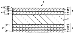
- FIG. 3 is a cross-sectional view showing an example of an infrared reflecting substrate according to the second aspect of the present invention.
- a transparent substrate 2 and a high refractive index dielectric film 4H and a low refractive index dielectric film 4L provided on one main surface of the transparent substrate 2 are alternately arranged.
- the first infrared reflective film 4 is laminated with five or more layers, and the high refractive index dielectric film 5H and the low refractive index dielectric film 5L provided on the other main surface of the transparent substrate 2 are alternately arranged.
- the second infrared reflective film 5 formed by laminating five or more layers.
- the infrared reflective substrate 1 of the second aspect for example, when the first infrared reflective film 4 has a thickness d [nm] and a refractive index n when the wavelength is ⁇ [nm], n ⁇ d /
- a dielectric film 411 having a ⁇ value of 0.44 to 0.55 (consisting of a high-refractive index dielectric film 4H and a low-refractive index dielectric film 4L) is continuously laminated in three or more layers. 1 and a dielectric film 421 (consisting of a high refractive index dielectric film 4H and a low refractive index dielectric film 4L) having an n ⁇ d / ⁇ value of 0.03 to 0.12.
- the second infrared reflective film 5 has an n ⁇ d / ⁇ value of 0.44 to 0.55, for example, where the thickness is d [nm] and the refractive index when the wavelength is ⁇ [nm] is n.
- the dielectric film 511 (consisting of a high-refractive index dielectric film 5H and a low-refractive index dielectric film 5L) can be formed only from the first stacked unit 51.
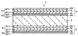
- the infrared reflective film 5 of the second embodiment is a variation of the embodiment shown in FIG. 3, for example, as shown in FIG. 4, the n ⁇ d / ⁇ value is 0.44 on one main surface of the transparent substrate 2.
- the film 521 may include a second stacked portion 52 in which two layers are continuously stacked.
- the second infrared reflective substrate 1 has at least the second laminated portion 42 in the first infrared reflective film 4 or has the second laminated portion 52 in the infrared reflective film 5 of the second mode. That's fine.
- the one having the second laminated portions 42 and 52 has the first laminated portion 41 on one main surface side of the transparent substrate 2 and the other main portion of the transparent substrate 2.
- the first laminated portion 51 may be disposed on the surface side.
- the second laminated portion 42 is provided on one main surface side of the transparent substrate 2, and the other transparent substrate 2 is provided on the other side.
- the second laminated portion 52 may be disposed on the main surface side of the transparent substrate 2, and, for example, as shown in FIG.
- the second laminated portion 52 may be arranged, the second laminated portion 42 may be arranged on the other main surface side of the transparent substrate 2, and the first laminated portion 41 may be arranged on the upper layer thereof.
- the infrared reflective substrate 1 according to the second aspect is characterized in that the infrared reflective films 4 and 5 are provided on both main surfaces of the transparent substrate 2 as described above.
- the dielectric film 4H and the dielectric film 4L are combined in five layers or more, and the dielectric film 5H and the dielectric film 5L are combined. It is sufficient that five or more layers are laminated.
- the number of layers of the infrared reflecting films 4 and 5 is preferably the same, but may be different.
- the number of layers of at least one of the infrared reflecting films 4 and 5 is less than 5, the visible light transmittance and the reflectance in the near-infrared region when laminated glass may be insufficient.
- the number of layers in each of the infrared reflecting films 4 and 5 is not necessarily limited as long as it is 5 layers or more. However, when the number of layers exceeds 9, the productivity decreases due to an increase in the manufacturing process, so that it is usually optical. From the viewpoint of achieving both properties and productivity, 5 to 9 layers are preferable, and 5 to 7 layers are more preferable.
- the first laminated portions 41 and 51 mainly constitute the infrared reflecting films 4 and 5, respectively, and are provided for obtaining good optical characteristics when a laminated glass is used.
- the first stacked portions 41 and 51 are composed of a dielectric film 411 (high refractive index dielectric film 4H and low refractive index dielectric film 4L) having an n ⁇ d / ⁇ value of 0.44 to 0.55. ), A dielectric film 511 (consisting of a high refractive index dielectric film 5H and a low refractive index dielectric film 5L) is continuously laminated.
- the second laminated portion 42 or 52 is not provided, the first laminated portion 41 or 51 on the side where the second laminated portion 42 or 52 is not provided is continuously laminated.
- n ⁇ d / ⁇ value of the dielectric films 411 and 511 is less than 0.44 or more than 0.55, the visible light transmittance and the reflectance in the near-infrared region when the laminated glass is used may not be sufficient. is there.
- the n ⁇ d / ⁇ values of the dielectric films 411 and 511 are preferably 0.44 to 0.53, and more preferably 0.45 to 0.52. Further, even when the number of layers of each of the dielectric films 411 and 511 is less than 3, the visible light transmittance and the reflectance in the near-infrared region when the laminated glass is used may not be sufficient.
- the dielectric film 411 and the dielectric film 511 can have different n ⁇ d / ⁇ values.
- the individual dielectric films 411 and the individual dielectric films 511 can have different n ⁇ d / ⁇ values.
- the first stacked unit 41 and the first stacked unit 51 are the same.
- the dielectric film 4H in the dielectric film 411 and the dielectric film 5H in the dielectric film 511 are the same or It is preferable that they have substantially the same n ⁇ d / ⁇ value
- the dielectric film 4L in the dielectric film 411 and the dielectric film 5L in the dielectric film 511 are the same or substantially the same n ⁇ d / ⁇ .
- a ⁇ value is preferred.
- the second laminated portions 42 and 52 are provided mainly for improving the color tone of the surface when the laminated glass is used.
- the second stacked portions 42 and 52 include dielectric films 421 and 521 (high refractive index dielectric films 4H and 5H and low refractive index dielectrics having n ⁇ d / ⁇ values of 0.03 to 0.12. Film 4L, 5L) is continuously laminated at least two layers. As described above, the second stacked portions 42 and 52 only need to be provided with at least one of the main surface and the other surface of the transparent substrate 2.
- the surface of the laminated glass may become an excessively reddish stimulus color.
- the n ⁇ d / ⁇ values of the dielectric films 421 and 521 are preferably 0.03 to 0.11, and more preferably 0.04 to 0.10. Further, when the number of layers of the dielectric films 421 and 521 is less than 2, when the laminated glass is used, the surface thereof may become an excessively reddish stimulating color, for example. On the other hand, when the number of layers of the dielectric films 421 and 521 exceeds two, when laminated glass is used, it does not affect the color tone of the surface, but in the first place the productivity decreases due to the increase in the number of layers. cause.
- the dielectric film 421 and the dielectric film 521 can have different n ⁇ d / ⁇ values.
- the individual dielectric films 421 and the individual dielectric films 521 can have different n ⁇ d / ⁇ values.
- the second stacked unit 42 and the second stacked unit 52 are the same.
- the dielectric film 4H in the dielectric film 421 and the dielectric film 5H in the dielectric film 521 are the same or It is preferable that the n ⁇ d / ⁇ values are substantially the same, and the dielectric film 4L in the dielectric film 421 and the dielectric film 5L in the dielectric film 521 are the same or substantially the same n ⁇ d /.
- a ⁇ value is preferred.
- the second infrared reflective substrate 1 can be manufactured basically in the same manner as the first infrared reflective substrate 1 except that the infrared reflective films 4 and 5 are formed on both surfaces of the transparent substrate 2.
- the second infrared reflective substrate 1 can also have good optical characteristics and color tone when used as a laminated glass, and a significant design change from the conventional film thickness design. And the productivity can be improved.
- the second infrared reflective substrate 1 is preferable because the infrared reflective films 4 and 5 are formed on both surfaces of the transparent substrate 2, so that deformation such as warpage during substrate manufacture can be suppressed.
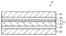
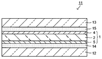
- FIG. 7 is a cross-sectional view showing an example of the laminated glass of the first aspect.
- the laminated glass 11 of the first aspect includes, for example, a pair of glass substrates 12 and 13 facing each other, a first infrared reflecting substrate 1 disposed between the pair of glass substrates 12 and 13, and a pair of glass substrates 12 and 13. And a pair of adhesive layers 14 and 15 disposed between the infrared reflective substrate 1 and the infrared reflective substrate 1.
- the 1st laminated glass 11 may use the 2nd infrared reflective board
- the first and second infrared reflecting substrates 1 those in which the transparent substrate 2 is made of a transparent resin film are usually used.
- the first and second infrared reflecting substrates 1 can use either of the main surfaces as the light incident side.
- the infrared reflecting film 3 is formed only on one main surface side like the first infrared reflecting substrate 1. It is preferable to use the main surface side having the infrared reflecting film 3 as the light incident side of the laminated glass.
- FIG. 9 is a cross-sectional view showing an example of the second laminated glass.
- the second laminated glass 11 includes a first infrared reflective substrate 1, a glass substrate 12 disposed to face the infrared reflective film 3 side of the first infrared reflective substrate 1, and the first infrared reflective substrate 1. It has the adhesive layer 14 arrange
- the 2 glass substrates 12 and 13 are not required like the 1st laminated glass 11, it can be set as a thing with favorable productivity.
- substrate 1 what the transparent substrate 2 consists of a glass plate is used normally.
- the second laminated glass 11 may be used as the light incident side on either the main surface side on which the first infrared reflecting substrate 1 is disposed or the main surface side on which the glass substrate 12 is disposed. Good.
- the members used for the first and second laminated glasses 11 can be basically the same.
- the adhesive layers 14 and 15 are provided for adhering the glass substrates 12 and 13 and the infrared reflective substrate 1, and are made of, for example, a thermoplastic resin composition containing a thermoplastic resin as a main component.
- the thickness of the adhesive layers 14 and 15 is not necessarily limited, for example, 0.1 to 1.5 mm is preferable, and 0.2 to 1.0 mm is more preferable.
- thermoplastic resin examples include thermoplastic resins conventionally used for this kind of application, such as plasticized polyvinyl acetal resin, plasticized polyvinyl chloride resin, saturated polyester resin, and plasticized saturated polyester resin.
- thermoplastic resins conventionally used for this kind of application such as plasticized polyvinyl acetal resin, plasticized polyvinyl chloride resin, saturated polyester resin, and plasticized saturated polyester resin.
- examples thereof include resins, polyurethane resins, plasticized polyurethane resins, ethylene-vinyl acetate copolymer resins, and ethylene-ethyl acrylate copolymer resins.
- a plasticized polyvinyl acetal resin is excellent in balance of various properties such as transparency, weather resistance, strength, adhesion, penetration resistance, impact energy absorption, moisture resistance, heat insulation, and sound insulation.
- These thermoplastic resins may use only 1 type and may use 2 or more types together.
- plasticization in the plasticized polyvinyl acetal resin means that it is plasticized, for example, by adding a plasticizer. The same applies to other plasticized resins. Of course, when the resin itself is thermoplastic, it may not be necessary to add a plasticizer.
- polyvinyl acetal resin examples include a polyvinyl formal resin obtained by reacting polyvinyl alcohol (hereinafter referred to as “PVA” if necessary) and formaldehyde, and a narrowly defined polyvinyl acetal resin obtained by reacting PVA and acetaldehyde.
- PVA polyvinyl formal resin obtained by reacting polyvinyl alcohol
- PVB polyvinyl butyral resin obtained by reacting PVA with n-butyraldehyde
- PVB transparency, weather resistance, strength, adhesive strength, penetration resistance
- these polyvinyl acetal type resins may use only 1 type, and may use 2 or more types together.
- the polyvinyl acetal resin generally has a degree of acetalization of preferably 40 to 85 mol%, more preferably 50 to 75 mol%, and a residual acetyl group content of 30 mol% or less is preferable. More preferably 0.5 to 24 mol%.
- the plasticizer examples include organic acid ester plasticizers such as monobasic organic acid esters and polybasic organic acid esters, and phosphoric acid plasticizers such as organic phosphoric acid and organic phosphorous acid. It is done.
- the amount of the plasticizer added varies depending on the average degree of polymerization of the thermoplastic resin, the average degree of polymerization of the polyvinyl acetal resin, the degree of acetalization, the amount of residual acetyl groups, etc., but is 10 to 80 with respect to 100 parts by mass of the thermoplastic resin. Part by mass is preferred.
- the addition amount of the plasticizer is less than 10 parts by mass, plasticization of the thermoplastic resin becomes insufficient, and molding may be difficult.
- strength may become inadequate.
- An infrared shielding agent can be contained in the thermoplastic resin composition.
- the infrared shielding agent include Re, Hf, Nb, Sn, Ti, Si, Zn, Zr, Fe, Al, Cr, Co, Ce, In, Ni, Ag, Cu, Pt, Mn, Ta, W, Examples thereof include metals such as V and Mo, oxides, nitrides, sulfides, or silicon compounds thereof, or inorganic fine particles doped with dopants such as Sb, F, or Sn.
- Sb is doped.
- Tin oxide fine particles (ATO fine particles) and Sn-doped indium oxide fine particles (ITO fine particles) are preferable, and among these, ITO fine particles are preferable.
- the ITO fine particles those having an average primary particle size of 100 nm or less are preferable. When the average particle diameter of the ITO fine particles exceeds 100 nm, the transparency may be insufficient.
- the content of the ITO fine particles is preferably 0.1 to 3.0 parts by mass, more preferably 0.1 to 1.0 part by mass with respect to 100 parts by mass of the thermoplastic resin. When the content of the ITO fine particles is less than 0.1 parts by mass, sufficient infrared shielding ability cannot be obtained, and when it exceeds 3.0 parts by mass, the visible light transmittance may be insufficient.
- the thermoplastic resin composition includes a thermoplastic resin, an infrared shielding agent contained as necessary, for example, an adhesion adjusting agent, a coupling agent, a surfactant, an antioxidant, a thermal stabilizer, One kind or two or more kinds of various additives such as a light stabilizer, an ultraviolet absorber, a fluorescent agent, a dehydrating agent, an antifoaming agent, an antistatic agent and a flame retardant can be contained.
- the adhesive layers 14 and 15 contain an infrared shielding agent
- the adhesive layer on the light emitting side of the infrared reflecting substrate 1 contains an infrared shielding agent.
- glass plates 12 and 13 known glass plates can be used.
- inorganic transparent glass plates such as clear glass plates, green glass plates and UV green glass plates, so-called organic transparent plates such as polycarbonate plates and polymethyl methacrylate plates.
- a glass plate can be used.
- the glass substrate on the light emitting side of the infrared reflective substrate 1 is preferably a UV green glass plate.
- the transparent substrate 2 (made of a glass plate) having the same role as the glass substrates 12 and 13, that is, the first infrared reflective substrate 1 shown in FIG. A green glass plate is preferred.
- the UV green glass plate is 68 to 74% by mass of SiO 2 in terms of oxide, 0.3 to 1.0% by mass of Fe 2 O 3 and 0.05 to 0.5% by mass of FeO. It is intended to indicate an ultraviolet-absorbing green glass having an ultraviolet transmittance at a wavelength of 350 nm of 1.5% or less and a minimum transmittance in the region of 550 to 1700 nm.
- the thickness of the glass substrates 12 and 13 is not necessarily limited, but is preferably 1 to 4 mm, more preferably 1.8 to 2.5 mm.
- the glass substrates 12 and 13 may be provided with a coating that imparts a water repellent function, a hydrophilic function, an antifogging function, and the like.
- the light incident angle when the light incident angle is defined as 0 degree when the light is perpendicularly incident on the surface thereof, for example, the surface on the light incident side described above, the light incident angle is 0 degree.
- the light incident angle chromaticity of 70 degrees is assumed to be used as a windshield of an automobile.
- the laminated glass 11 of the present invention preferably has a solar reflectance (Re) defined by JIS R3106-1998 of 28% or more, and preferably has a visible light transmittance (Tv) of 70% or more.
- the visible light reflectance (Rv) is preferably 12% or less.
- an infrared shielding agent is contained in the adhesive layers 14 and 15 on the light emitting side of the infrared reflective substrate 1 as described above, and an infrared ray of the glass substrates 12 and 13 is included. It is effective to use a UV green glass plate for the light emitting side of the reflective substrate 1.
- the laminated glass 11 of the present invention has good optical properties, and particularly has a good color tone on the surface, and therefore can be suitably used as a window material for automobiles, railways, ships, various buildings, etc. It can be suitably used for an automobile windshield or the like.
- Such a laminated glass 11 can be manufactured in the same manner as a conventional laminated glass except that the above-described infrared reflective substrate 1 is used.
- a glass substrate 12 for example, a glass substrate 12, an adhesive sheet (adhesive layer 14), an infrared reflective substrate 1, an adhesive sheet (adhesive layer 15), and a glass substrate 13 are laminated in this order to form a laminate. Then, it can manufacture by performing pre-crimping and this press-bonding with respect to this laminated body.
- the adhesive sheet (adhesive layer 14), the infrared reflecting substrate 1, and the adhesive sheet (adhesive layer 15) are superposed in this order, and the heating and pressurization at a temperature of 40 to 80 ° C. and a pressure of 0.1 to 1.0 MPa, for example. May be manufactured by superimposing glass substrates 12 and 13 on both main surfaces of the pre-laminated body to form a laminated body, and pre-crimping and main-pressing the laminated body. .
- the pre-compression is intended to deaerate the constituent members.
- the laminated body is placed in a vacuum bag such as a rubber bag connected to an exhaust system, and the internal pressure is 100 kPa or less, preferably about 1 to 36 kPa. It can be carried out by maintaining at 70 to 130 ° C. for 10 to 90 minutes while degassing so that
- Preliminary pressure bonding can be performed sufficiently by setting the temperature to 70 ° C or higher. On the other hand, by setting the temperature to 130 ° C. or lower, the generation of cracks due to excessive thermal shrinkage of the infrared reflective substrate 1 can be suppressed. From the viewpoint of more effectively pre-bonding, the temperature is preferably 90 ° C. or higher, more preferably 110 ° C. or higher.
- pre-bonding can be sufficiently performed by setting the time to 10 minutes or more.
- the time is set to 90 minutes or less, a decrease in productivity can be suppressed, and generation of cracks due to excessive thermal contraction of the infrared reflective substrate 1 can be suppressed.
- the time is preferably 20 to 60 minutes from the viewpoint of pre-pressing more effectively and efficiently.
- the main pressure bonding is performed in order to sufficiently bond the glass substrates 12 and 13 and the infrared reflection substrate 1 with an adhesive sheet (adhesive layers 12 and 13).
- a pre-pressure bonded body obtained by pre-pressure bonding is applied to an autoclave. It can be carried out at a temperature of 120 to 150 ° C. and a pressure of 0.98 to 1.47 MPa.
- the main pressure bonding is more preferably performed at 130 to 140 ° C. and a pressure of 1.1 to 1.4 MPa.
- the time is preferably 30 to 90 minutes, more preferably 45 to 75 minutes. Adequate adhesion can be performed by setting the temperature, pressure, or time for the main pressure bonding within the above range.
- substrate 1 can be suppressed, and productivity etc. can be made favorable.
- Example 1 An infrared reflecting substrate having the structure shown in Table 1 (thick frame portion) was manufactured.
- the numerical value in the thick frame represents the thickness of the film, and the unit is [nm]. Further, n ⁇ d / ⁇ values at this time are as shown in Table 4.
- a PET film having a size of 100 mm ⁇ 100 mm and a thickness of 100 ⁇ m in which an easy-adhesion layer (PET (TR) in the table) was provided on the PET film main body (PET in the table) was used.
- This PET film is set in a sputtering film forming apparatus, and a high refractive index dielectric film (TiO 2 film) and a low refractive index dielectric film (SiO 2 film) are alternately formed on the surface by a magnetron sputtering method.
- a high refractive index dielectric film TiO 2 film
- SiO 2 film low refractive index dielectric film
- the TiO 2 film was formed by using a Ti target and introducing 2500 sccm of argon as an inert gas and 700 sccm of oxygen gas as a reactive gas into the oxidation zone while rotating a drum on which a PET film was set at 150 rpm and 1000 W using an ECR oxidation source.
- the microwave was introduced into a vacuum chamber, and AC power of 15 kW was applied to form. At this time, the pressure in the tank was 0.58 Pa.
- SiO 2 film is introduced argon gas 2500sccm using a Si target, a microwave 1000W by while the drum was set PET film while oxygen gas was introduced 900sccm rotated at 150 rpm ECR oxide source in a vacuum chamber, It was formed by applying 15 kW of AC power. At this time, the pressure in the tank was 0.55 Pa. The thickness of the dielectric film was adjusted by changing the film formation time.
- a laminated glass having the configuration shown in Table 1 was manufactured using this infrared reflective substrate. That is, transparent soda lime glass (FL in the table) having a size of 100 mm ⁇ 100 mm and a thickness of 2 mm was used for the glass substrate on the light incident side (upper in the table). On the other hand, a UV green glass plate (in the table, UVFL) that cuts the UV wavelength of the same size and thickness was used for the glass substrate on the light emitting side (in the table, on the bottom side). Moreover, the PVB film (PVB (CL) in a table
- PVB film containing an infrared shielding agent in the table, PVB (IR cut), manufactured by Asahi Glass Co., Ltd., trade name: Cool Veil) was used for the adhesive sheet (adhesive layer) on the light emitting side.
- Example 2 As shown in Table 1, an infrared reflecting substrate was manufactured in substantially the same manner as in Example 1 by changing the SiO 2 film to an MgF 2 film. Incidentally, MgF 2 film was deposited by vacuum evaporation method using an EB evaporation source installed in the same device. A laminated glass was produced using this infrared reflective substrate in substantially the same manner as in Example 1.
- Example 3 As shown in Table 1, an infrared reflective film was formed by alternately laminating TiO 2 films and SiO 2 films on the side opposite to the easy-adhesion layer of the PET film to produce an infrared reflective substrate. A laminated glass was produced in substantially the same manner as in Example 1 using this infrared reflective substrate so that the PET film side was the light incident side.
- an infrared reflecting substrate is formed by alternately laminating TiO 2 films and SiO 2 films directly on soda lime glass (FL) or UV green glass plate (UVFL) to produce an infrared reflecting substrate. did.
- a soda lime glass (FL) or a UV green glass plate (UVFL) is disposed on this infrared reflecting substrate via a PVB film (PVB (CL)) not containing an infrared shielding agent, and is preliminarily crimped in the same manner as in Example 1.
- the laminated glass was manufactured by performing the main pressure bonding.
- Example 11 to 16 As shown in Table 2, an infrared reflecting substrate was manufactured by alternately laminating TiO 2 films and SiO 2 films on both sides of the PET film to form infrared reflecting films. Further, a laminated glass was produced in the same manner as in Example 1 using this infrared reflective substrate.
- an infrared reflecting substrate was manufactured by alternately laminating a TiO 2 film and an SiO 2 film on one side of a PET film having an easy-adhesion layer to form an infrared reflecting film. Moreover, it was set as the laminated glass like this Example 1 using this infrared reflective board
- the surface of a laminated glass is obtained by repeatedly laminating a dielectric film having a high refractive index and a dielectric film having a low refractive index with a combination of specific thicknesses. It is possible to provide a laminated glass having a good intermediate color tone that does not have a stimulating color, and is useful as a window glass for automobiles and other various vehicles, particularly as a front window glass.
- the entire contents of the specification, claims, drawings and abstract of Japanese Patent Application No. 2010-161275 filed on July 16, 2010 are incorporated herein as the disclosure of the present invention. .
Landscapes
- Chemical & Material Sciences (AREA)
- Physics & Mathematics (AREA)
- Materials Engineering (AREA)
- Chemical Kinetics & Catalysis (AREA)
- General Chemical & Material Sciences (AREA)
- Geochemistry & Mineralogy (AREA)
- Life Sciences & Earth Sciences (AREA)
- Organic Chemistry (AREA)
- Engineering & Computer Science (AREA)
- General Physics & Mathematics (AREA)
- Optics & Photonics (AREA)
- Health & Medical Sciences (AREA)
- Toxicology (AREA)
- Laminated Bodies (AREA)
- Joining Of Glass To Other Materials (AREA)
Abstract
合わせガラスとしたときに表面の色調が刺激色を帯びない良好な中間的色調となる赤外線反射基板を提供すること。 赤外線反射基板1は、透明基板2と、該透明基板2の一方の主面に設けられ、高屈折率の誘電体膜3Hと低屈折率の誘電体膜3Lとが交互に7層以上積層されてなる赤外線反射膜3とを有する。該赤外線反射膜3は、厚さをd[nm]、波長がλ[nm]のときの屈折率をnとしたとき、n・d/λ値が0.44~0.55である誘電体膜311が5層以上連続して積層されてなる第1の積層部31と、n・d/λ値が0.03~0.12である誘電体膜321が2層連続して積層されてなる第2の積層部32とを有する。
Description
本発明は、赤外線反射基板および合わせガラスに係り、特に表面の色調が良好な合わせガラスを得られる赤外線反射基板、およびこれを用いた合わせガラスに関する。
従来、車両等のフロントガラスに使用する合わせガラスとして、室内の温度上昇や冷房負荷を抑制するために対向する一対のガラス基板間に太陽光線中の赤外線(熱線)の透過を遮断する赤外線反射膜を配置したものが知られている。赤外線反射膜は、例えば透明樹脂フィルム等の透明基材上に形成されて赤外線反射基板を構成している。赤外線反射膜としては、例えば酸化物膜と金属膜とを交互に積層したもの、また例えば高屈折率の誘電体膜と低屈折率の誘電体膜とを交互に積層したものが知られている。
車輌用ガラス等については、赤外線遮蔽能が高いことに加えて、可視光透過率や電波透過性が高いことが要求される。上述した赤外線反射膜のうち、酸化物膜と金属膜とを交互に積層したものは赤外線遮蔽能が高いものの非電波透過性であり、ガレージオープナーや携帯電話機等の電波を利用した機器は車内において電波を受発信できないおそれがある。これに対し、高屈折率の誘電体膜と低屈折率の誘電体膜とを交互に積層したものは金属膜を有しないために良好な電波透過性を有している。
高屈折率の誘電体膜と低屈折率の誘電体膜とを交互に積層したものとして、例えば誘電体膜の屈折率をn、厚みをdとしたとき、波長λが900~1400nmの範囲の赤外線についてn・d値を225~350nmとしたものが知られている(例えば、特許文献1参照)。このようなものによれば、可視光透過率や近赤外線領域における反射率を高くすることができる、と記載されている。
上記したように、高屈折率の誘電体膜と低屈折率の誘電体膜とを交互に積層したものについて、例えば誘電体膜のn・d値を所定の範囲内とすることで、可視光透過率や近赤外線領域における反射率を高くできることが知られている。しかしながら、高屈折率の誘電体膜と低屈折率の誘電体膜とを同じような厚さの組み合わせで繰り返して積層するものについては、合わせガラスとしたときにその表面が刺激色、例えば過度に赤味や青味を帯びた色調となることがあり、実用上好ましくないことがある。
本発明は、上記した課題を解決するためになされたものであって、透明基板に高屈折率の誘電体膜と低屈折率の誘電体膜とからなる赤外線反射膜を有する基板(以下、赤外線反射基板という)において、合わせガラスとしたときに表面の色調が刺激色を帯びない良好な中間的色調となるものを提供することを目的としている。また、本発明は、このような赤外線反射基板を用いた表面の色調が良好な合わせガラスを提供すること、特に車両用ガラスとして最適な合わせガラス提供することを目的としている。
本発明の第1の態様の赤外線反射基板は、透明基板と、該透明基板の一方の主面に設けられ、高屈折率の誘電体膜と低屈折率の誘電体膜とが交互に7層以上積層されてなる赤外線反射膜とを有する。そして、該赤外線反射膜は、厚さをd[nm]、波長がλ[nm]のときの屈折率をnとしたとき、n・d/λ値が0.44~0.55である高屈折率の誘電体膜と低屈折率の誘電体膜とが交互に5層以上連続して積層されてなる第1の積層部と、n・d/λ値が0.03~0.12である高屈折率の誘電体膜と低屈折率の誘電体膜とが少なくとも2層連続して積層されてなる第2の積層部とを有することを特徴とする。
本発明の第2の態様の赤外線反射基板は、透明基板と、該透明基板の一方の主面に設けられ、高屈折率の誘電体膜と低屈折率の誘電体膜とが交互に5層以上積層されてなる第1の赤外線反射膜と、該透明基板の他方の主面に設けられ、高屈折率の誘電体膜と低屈折率の誘電体膜とが交互に5層以上積層されてなる第2の赤外線反射膜とを有する。そして、該第1の赤外線反射膜、該第2の赤外線反射膜の少なくとも一方は、厚さをd[nm]、波長がλ[nm]のときの屈折率をnとしたとき、n・d/λ値が0.44~0.55である高屈折率の誘電体膜と低屈折率の誘電体膜とが交互に3層以上連続して積層されてなる第1の積層部と、n・d/λ値が0.03~0.12である高屈折率の誘電体膜と低屈折率の誘電体膜とが少なくとも2層連続して積層されてなる第2の積層部とを有することを特徴とする。
本発明の第1の態様の合わせガラスは、対向する一対のガラス基板と、該一対のガラス基板間に配置される赤外線反射基板と、該一対のガラス基板と該赤外線反射基板との間に配置される一対の接着層とを有する。そして、該赤外線反射基板が上記した本発明の第1または第2の態様の赤外線反射基板であって、かつその透明基板が樹脂フィルムからなることを特徴とする。
本発明の第2の態様の合わせガラスは、一方の主面のみに赤外線反射膜を有する赤外線反射基板と、該赤外線反射基板の該赤外線反射膜側に対向して配置されるガラス基板と、該赤外線反射基板と該ガラス基板との間に配置される接着層とを有する。そして、該赤外線反射基板が上記した本発明の第1の態様の赤外線反射基板であって、かつその透明基板がガラス板からなることを特徴とする。
本発明の赤外線反射基板は、高屈折率の誘電体膜と低屈折率の誘電体膜とが交互に積層されてなる赤外線反射膜を有するものであり、上記したように、該赤外線反射膜が、n・d/λ値が0.44~0.55である高屈折率の誘電体膜と低屈折率の誘電体膜とが連続して積層されてなる第1の積層部と、n・d/λ値が0.03~0.12である高屈折率の誘電体膜と低屈折率の誘電体膜とが連続して第2の積層部とを有することを特徴としている。このような赤外線反射基板によれば、合わせガラスとしたときにその表面の色調を良好なものとすることができる。
以下、本発明の赤外線反射基板について説明する。
まず、本発明の第1の態様の赤外線反射基板について説明する。
図1は、本発明の第1の態様の赤外線反射基板の一例を示す断面図である。
図1は、本発明の第1の態様の赤外線反射基板の一例を示す断面図である。
第1の態様の赤外線反射基板1は、透明基板2と、該透明基板2の一方の主面に設けられ、高屈折率の誘電体膜3Hと低屈折率の誘電体膜3Lとが交互に7層以上積層されてなる赤外線反射膜3とを有するものである。なお、図1に示す赤外線反射膜3は、誘電体膜3Hと誘電体膜3Lとを合わせて9層有するものである。
この赤外線反射膜3は、厚さをd[nm]、波長がλ[nm]のときの屈折率をnとしたとき、n・d/λ値が0.44~0.55である誘電体膜311(高屈折率の誘電体膜3Hおよび低屈折率の誘電体膜3Lからなる)が5層以上連続して積層されてなる第1の積層部31と、n・d/λ値が0.03~0.12である誘電体膜321(高屈折率の誘電体膜3Hおよび低屈折率の誘電体膜3Lからなる)が少なくとも2層連続して積層されてなる第2の積層部32とを有することを特徴としている。ここにおいて、高屈折率の誘電体膜および低屈折率の誘電体膜からなる誘電体層が複数層連続して積層されてなる」における「連続して」とは、高屈折率の誘電体膜と低屈折率の誘電体膜との間に介在層が存在しない状態で積層されてなることを意味する。
なお、第1の積層部31と第2の積層部32とは、図1に示すように、透明基板2の一方の主面側に第1の積層部31が、その上層に第2の積層部32が配置されていてもよいし、例えば図2に示すように、透明基板2の一方の主面側に第2の積層部32が、その上層に第1の積層部31が配置されていてもよい。また、赤外線反射膜3の表面上には、保護層等の別の機能を有する層が形成されていてもよい。さらに、赤外線反射膜3は、図1、2に示されているように、必ずしも透明基板2側が高屈折率の誘電体膜3Hである必要はない。
赤外線反射膜3は、光の干渉を利用して赤外領域(波長域:780nm~1000nm)の光を選択的に反射するものであり、図1、2に示すように高屈折率の誘電体膜3Hと低屈折率の誘電体膜3Lが合わせて7層以上積層されて構成されている。誘電体膜3H、3Lの合計の層数が7層未満の場合、合わせガラスとしたときの可視光透過率や近赤外線領域における反射率が十分でなくなるおそれがある。
誘電体膜3H、3Lの層数は7層以上であれば必ずしも制限されるものではないが、13層を超えると製造工程の増加による生産性の低下が顕著となることから、通常は光学特性と生産性とを両立させる観点から、7~13層が好ましく、7~11層がより好ましく、7~9層がさらに好ましい。
第1の積層部31は、赤外線反射膜3を主として構成するものであり、合わせガラスとしたときに良好な光学特性を得るために設けられている。第1の積層部31は、n・d/λ値が0.44~0.55である高屈折率の誘電体膜と低屈折率の誘電体膜の誘電体膜311が5層以上連続して積層されてなるものである。なお、個々の誘電体膜311同士は異なるn・d/λ値とすることができるが、通常、誘電体膜3H同士、誘電体膜3L同士は、同一または実質的に同一のn・d/λ値とされている。
誘電体膜311のn・d/λ値が0.44未満または0.55を超える場合、合わせガラスとしたときの可視光透過率や近赤外線領域における反射率等が十分でなくなるおそれがある。誘電体膜311のn・d/λ値は、0.44~0.53が好ましく、0.45~0.52がより好ましい。また、誘電体膜311の層数が5層未満の場合についても、合わせガラスとしたときの可視光透過率や近赤外線領域における反射率等が十分でなくなるおそれがある。
一方、第2の積層部32は、主として合わせガラスとしたときの表面の色調を良好にするために設けられている。第2の積層部32は、n・d/λ値が0.03~0.12である高屈折率の誘電体膜と低屈折率の誘電体膜の誘電体膜321が2層連続して積層されてなるものである。なお、個々の誘電体膜321のn・d/λ値についても互いに異なるものとすることができる。
誘電体膜321のn・d/λ値が0.03未満または0.12を超える場合、合わせガラスとしたときに、その表面が過度に赤味を帯びた刺激色となるおそれがある。誘電体膜321のn・d/λ値は、0.03~0.11が好ましく、0.04~0.10がより好ましい。誘電体膜321の層数が2層未満の場合、合わせガラスとしたときに、その表面が過度に赤味を帯びた刺激色となるおそれがある。一方、誘電体膜321の層数が2層を超える場合、合わせガラスとしたときに、表面の色調に対して影響を与えるものではないが、そもそも層数が増えることにより生産性の低下を引き起こす。
上記したように、赤外線反射膜3を第1の積層部31と第2の積層部32とからなるものとすることで、合わせガラスとしたときの光学特性および色調を良好にすることができる。また、このようなものとすることで、光学特性は主として第1の積層部31により達成することができ、また表面の色調は主として第2の積層部32により達成することができ、互いの機能を分離することができるために個別の膜厚設計が可能となる。これにより、従来の膜厚設計からの大幅な設計変更を抑制し、生産性の良好なものとすることができる。
ここで、n・d/λ値は、一般に誘電体膜の屈折率nが波長λによって変化することから、波長λによらない指標とするために、屈折率nと厚さdとの積を波長λで除したものである。なお、n・d/λ値は波長λによらず一定となることから、本発明においては少なくとも1つの波長λのときに所定のn・d/λ値を有するものとなっていればよい。このような波長λとしては、特に限定されるものではないが、通常は200~2100nmの範囲内の1つの波長λである。より代表的には、波長λとしては、300~1200nmが挙げられる。
誘電体膜311、321のn・d/λ値は、主として厚さdを変更することにより調整することができる。例えば、全体として誘電体膜321の厚さを誘電体膜311の厚さよりも薄くすることで、誘電体膜321のn・d/λ値を誘電体膜311のn・d/λ値よりも小さくすることができる。また、全体として誘電体膜3Lの厚さに比べて誘電体膜3Hの厚さを薄くすることで、誘電体膜3Hのn・d/λ値と誘電体膜3Lのn・d/λ値とを同様なものとすることができる。
具体的には、第1の積層部における誘電体膜311における高屈折率の誘電体膜3Hの厚さは、その屈折率によっても若干異なるが、90~115nmが好ましく、90~110nmがより好ましい。また、低屈折率の誘電体膜3Lの厚さは、150~195nmが好ましく、155~190nmがより好ましい。このような厚さとすることで、誘電体膜311のn・d/λ値を0.44~0.55としやすくなる。
一方、第2の積層部における誘電体膜321における高屈折率の誘電体膜3Hの厚さは、その屈折率によっても若干異なるが、5~30nmが好ましく、5~25nmがより好ましい。また、低屈折率の誘電体膜3Lの厚さは、10~50nmが好ましく、15~45nmがより好ましい。このような厚さとすることで、誘電体膜321のn・d/λ値を0.03~0.12としやすくなる。
誘電体膜3Hは、屈折率(波長550nmでの屈折率、以下同様)が1.9以上、好ましくは1.9~2.5の誘電体からなるものであり、例えば酸化ニオブ、酸化タンタル、酸化チタン、酸化ジルコニウム、および酸化ハフニウム等の高屈折率の誘電体材料の中から選ばれる少なくとも1種からなるものが好ましい。
一方、誘電体膜3Lは、屈折率が1.5以下、好ましくは1.2~1.5の誘電体からなるものであり、例えば酸化シリコン、およびフッ化マグネシウム等の低屈折率の誘電体材料の中から選ばれる少なくとも1種からなるものが好ましい。
このような赤外線反射膜3は、公知の成膜方法を適用して形成することができ、例えばマグネトロンスパッタリング法、電子線蒸着法、真空蒸着法、化学蒸着法等により形成することができる。また、n・d/λ値の調整は主として成膜時間の調整により行うことができ、具体的には成膜時間により上記したような厚さに調整することで行うことができる。
透明基板2としては、例えばポリカーボネート、ポリメチルメタクリレート(PMMA)、ポリエチレンテレフタレート(PET)、ポリエチレンナフタレート(PEN)、ポリイミド、ポリエーテルスルフォン、ポリアリレート、ナイロン、シクロオレフィンポリマー等からなる透明樹脂フィルムを用いることができる。これらの中でも、比較的に高強度であり、合わせガラスを製造する際の損傷を抑制しやすいことから、ポリエチレンテレフタレート(PET)を好適に用いることができる。なお、本明細書における透明基板とは、フィルム状のものも含め、透明基板をいう。
透明樹脂フィルムの厚さは、必ずしも限定されるものではないが、5~200μmが好ましく、10~100μmがより好ましい。透明樹脂フィルムの厚さを5μm以上とすることで、ある程度の剛性をもたせて折り目を発生しにくくし、また赤外線反射膜3の成膜時の熱による変形も抑制しやすい。また、200μm以下とすることで、成形性を良好とし、合わせガラスにするときのエッジ部分のエアライン(フィルムエッジ部に入り込んだ空気が抜けず、白い線のように見える不具合)の発生も抑制しやすい。
また、透明基板2としては、公知のガラス板を用いることもでき、例えばクリアガラス板、グリーンガラス板、UVグリーンガラス板(紫外線吸収グリーンガラス板)等の無機透明ガラス板、ポリカーボネート板、ポリメチルメタクリレート板等の有機透明ガラス板等を用いることができる。透明基板2をガラス板とすることで、例えば他のガラス板を対向配置することにより容易に合わせガラスを得ることができるために好ましい。
次に、本発明の第2の態様の赤外線反射基板について説明する。
図3は、本発明の第2の態様の赤外線反射基板の一例を示す断面図である。
図3は、本発明の第2の態様の赤外線反射基板の一例を示す断面図である。
第2の態様の赤外線反射基板1は、透明基板2と、該透明基板2の一方の主面に設けられた、高屈折率の誘電体膜4Hと低屈折率の誘電体膜4Lとが交互に5層以上積層されてなる第1の赤外線反射膜4と、透明基板2の他方の主面に設けられた、高屈折率の誘電体膜5Hと低屈折率の誘電体膜5Lとが交互に5層以上積層されてなる第2の赤外線反射膜5とを有するものである。
第2の態様の赤外線反射基板1は、例えば第1の赤外線反射膜4が、厚さをd[nm]、波長がλ[nm]のときの屈折率をnとしたとき、n・d/λ値が0.44~0.55である誘電体膜411(高屈折率の誘電体膜4Hおよび低屈折率の誘電体膜4Lをからなる)が3層以上連続して積層されてなる第1の積層部41と、n・d/λ値が0.03~0.12である誘電体膜421(高屈折率の誘電体膜4Hおよび低屈折率の誘電体膜4Lからなる)が少なくとも2層連続して積層されてなる第2の積層部42とを有することを特徴としている。第2の赤外線反射膜5は、例えば、厚さをd[nm]、波長がλ[nm]のときの屈折率をnとしたとき、n・d/λ値が0.44~0.55である誘電体膜511(高屈折率の誘電体膜5Hおよび低屈折率の誘電体膜5Lをからなる)が積層されてなる第1の積層部51のみからなるものとすることができる。
なお、第2の態様の赤外線反射膜5は、図3に示した態様のバリエーションとして、例えば図4に示すように、透明基板2の一方の主面にn・d/λ値が0.44~0.55である誘電体膜511が3層以上連続して積層されてなる第1の積層部51と、その上層にn・d/λ値が0.03~0.12である誘電体膜521が2層連続して積層されてなる第2の積層部52とを有するものであってもよい。第2の赤外線反射基板1は、少なくとも第1の赤外線反射膜4に第2の積層部42を有するか、または第2の態様の赤外線反射膜5に第2の積層部52を有するものであればよい。
このように第2の積層部42、52を有するものについては、図4に示すように、透明基板2の一方の主面側に第1の積層部41が、また透明基板2の他方の主面側に第1の積層部51が配置されていてもよいし、例えば図5に示すように、透明基板2の一方の主面側に第2の積層部42が、また透明基板2の他方の主面側に第2の積層部52が配置されていてもよいし、また例えば図6に示すように、透明基板2の一方の主面側に第1の積層部51が、その上層に第2の積層部52が配置され、透明基板2の他方の主面側に第2の積層部42が、その上層に第1の積層部41が配置されていてもよい。
第2の態様の赤外線反射基板1は、上記したように透明基板2の両主面に赤外線反射膜4、5が設けられていることを特徴としている。このように両主面に赤外線反射膜4、5が設けられるものについては、誘電体膜4Hと誘電体膜4Lとが合わせて5層以上、また誘電体膜5Hと誘電体膜5Lとが合わせて5層以上積層されていればよい。なお、赤外線反射膜4、5の層数は、通常、同一の層数が好ましいが、異なる層数とすることもできる。
赤外線反射膜4、5の少なくとも一方の層数が5層未満の場合、合わせガラスとしたときの可視光透過率や近赤外線領域における反射率が十分でなくなるおそれがある。赤外線反射膜4、5における層数はそれぞれ5層以上であれば必ずしも制限されるものではないが、9層を超えると製造工程の増加による生産性の低下が顕著となることから、通常は光学特性と生産性とを両立させる観点から、5~9層が好ましく、5~7層がより好ましい。
第1の積層部41、51は、それぞれ赤外線反射膜4、5を主として構成するものであり、合わせガラスとしたときの良好な光学特性を得るために設けられている。第1の積層部41、51は、n・d/λ値が0.44~0.55である誘電体膜411(高屈折率の誘電体膜4Hおよび低屈折率の誘電体膜4Lからなる)、誘電体膜511(高屈折率の誘電体膜5Hおよび低屈折率の誘電体膜5Lからなる)が3層以上連続して積層されてなるものである。なお、第2の積層部42または52が設けられない場合、その設けられない側の第1の積層部41または51については5層以上連続して積層される。
誘電体膜411、511のn・d/λ値が0.44未満または0.55を超える場合、合わせガラスとしたときの可視光透過率や近赤外線領域における反射率等が十分でなくなるおそれがある。誘電体膜411、511のn・d/λ値は、0.44~0.53が好ましく、0.45~0.52がより好ましい。また、誘電体膜411、511のそれぞれの層数が3層未満の場合についても、合わせガラスとしたときの可視光透過率や近赤外線領域における反射率等が十分でなくなるおそれがある。
ここで、誘電体膜411と誘電体膜511とは、異なるn・d/λ値とすることができる。また、個々の誘電体膜411同士、個々の誘電体膜511同士も異なるn・d/λ値とすることができる。しかし、通常、第1の積層部41と第1の積層部51とは同様であることが好ましく、例えば誘電体膜411における誘電体膜4Hと誘電体膜511における誘電体膜5Hとは同一または実質的に同一のn・d/λ値であることが好ましく、また誘電体膜411における誘電体膜4Lと誘電体膜511における誘電体膜5Lとは同一または実質的に同一のn・d/λ値であることが好ましい。なお、第1の積層部41、第2の積層部51が配置される位置については、例えば図6に示すように異なっていても構わない。
一方、第2の積層部42、52は、主として合わせガラスとしたときの表面の色調を良好にするために設けられる。第2の積層部42、52は、n・d/λ値が0.03~0.12である誘電体膜421、521(高屈折率の誘電体膜4H、5Hおよび低屈折率の誘電体膜4L、5Lからなる)が少なくとも2層連続して積層されてなるものである。なお、上記したように、第2の積層部42、52は、透明基板2の主面と他の面の少なくとも一方が設けられていればよい。
誘電体膜421、521のn・d/λ値が0.03未満または0.12を超える場合、合わせガラスとしたときに、その表面が過度に赤味を帯びた刺激色となるおそれがある。誘電体膜421、521のn・d/λ値は、0.03~0.11が好ましく、0.04~0.10がより好ましい。また、誘電体膜421、521の層数が2層未満の場合、合わせガラスとしたときに、その表面が例えば過度に赤味を帯びた刺激色となるおそれがある。一方、誘電体膜421、521の層数が2層を超える場合、合わせガラスとしたときに、表面の色調に対して影響を与えるものではないが、そもそも層数が増えることにより生産性の低下を引き起こす。
ここで、誘電体膜421と誘電体膜521とは異なるn・d/λ値とすることができる。また、個々の誘電体膜421同士、個々の誘電体膜521同士も異なるn・d/λ値とすることができる。しかし、通常、第2の積層部42と第2の積層部52とは同様であることが好ましく、例えば誘電体膜421における誘電体膜4Hと誘電体膜521における誘電体膜5Hとは同一または実質的に同一のn・d/λ値であることが好ましく、また誘電体膜421における誘電体膜4Lと誘電体膜521における誘電体膜5Lとは同一または実質的に同一のn・d/λ値であることが好ましい。
第2の赤外線反射基板1は、透明基板2の両面に赤外線反射膜4、5が形成されることを除き、基本的に第1の赤外線反射基板1と同様にして製造することができる。第2の赤外線反射基板1についても、第1の赤外線反射基板1と同様に合わせガラスとしたときの光学特性および色調を良好にすることができ、また従来の膜厚設計からの大幅な設計変更を抑制し、生産性の良好なものとすることができる。特に、第2の赤外線反射基板1によれば、透明基板2の両面に赤外線反射膜4、5が形成されるために、基板製造時の反りなどの変形を抑制することができるために好ましい。
次に、本発明の合わせガラスについて説明する。
まず、本発明の第1の合わせガラスについて説明する。
図7は、第1の態様の合わせガラスの一例を示す断面図である。
図7は、第1の態様の合わせガラスの一例を示す断面図である。
第1の態様の合わせガラス11は、例えば対向する一対のガラス基板12、13と、一対のガラス基板12、13間に配置される第1の赤外線反射基板1と、一対のガラス基板12、13と赤外線反射基板1との間に配置される一対の接着層14、15とを有することを特徴としている。なお、第1の合わせガラス11は、例えば図8に示すように、第2の赤外線反射基板1を用いたものであってもよい。
第1、第2の赤外線反射基板1としては、通常、透明基板2が透明樹脂フィルムからなるものが用いられる。第1、第2の赤外線反射基板1は、両主面のいずれを光線入射側として用いることもできるが、例えば第1の赤外線反射基板1のように一方の主面側のみに赤外線反射膜3を有するものについては、この赤外線反射膜3を有する主面側を合わせガラスの光線入射側として用いることが好ましい。
次に、本発明の第2の態様の合わせガラスについて説明する。
図9は、第2の合わせガラスの一例を示す断面図である。
図9は、第2の合わせガラスの一例を示す断面図である。
第2の合わせガラス11は、第1の赤外線反射基板1と、第1の赤外線反射基板1の赤外線反射膜3側に対向して配置されるガラス基板12と、第1の赤外線反射基板1とガラス基板12との間に配置される接着層14とを有することを特徴としている。
第2の合わせガラス11によれば、第1の合わせガラス11のように2枚のガラス基板12、13を必要としないことから、生産性の良好なものとすることができる。なお、第1の赤外線反射基板1としては、通常、透明基板2がガラス板からなるものが用いられる。また、第2の合わせガラス11は、第1の赤外線反射基板1が配置された主面側、またはガラス基板12が配置された主面側のいずれの主面側を光線入射側として用いてもよい。
第1、第2の合わせガラス11に用いられる部材は、基本的に同様なものとすることができる。接着層14、15は、ガラス基板12、13と赤外線反射基板1とを接着するために設けられるものであり、例えば熱可塑性樹脂を主成分とする熱可塑性樹脂組成物からなるものである。接着層14、15の厚さは必ずしも限定されるものではないものの、例えば0.1~1.5mmが好ましく、0.2~1.0mmがより好ましい。
熱可塑性樹脂としては、従来からこの種の用途に用いられている熱可塑性樹脂が挙げられ、例えば可塑化ポリビニルアセタール系樹脂、可塑化ポリ塩化ビニル系樹脂、飽和ポリエステル系樹脂、可塑化飽和ポリエステル系樹脂、ポリウレタン系樹脂、可塑化ポリウレタン系樹脂、エチレン-酢酸ビニル共重合体系樹脂、エチレン-エチルアクリレート共重合体系樹脂等が挙げられる。
これらの中でも、透明性、耐候性、強度、接着力、耐貫通性、衝撃エネルギー吸収性、耐湿性、遮熱性、および遮音性等の諸特性のバランスに優れることから、可塑化ポリビニルアセタール系樹脂が好適なものとして挙げられる。これらの熱可塑性樹脂は、1種のみを用いてもよいし、2種以上を併用してもよい。なお、可塑化ポリビニルアセタール系樹脂における「可塑化」とは、例えば可塑剤の添加により可塑化されていることを意味する。その他の可塑化樹脂についても同様な場合もある。勿論、樹脂自体が熱可塑性である場合には、可塑剤を添加する必要性がない場合もある。
ポリビニルアセタール系樹脂としては、例えばポリビニルアルコール(以下、必要に応じて「PVA」という)とホルムアルデヒドとを反応させて得られるポリビニルホルマール樹脂、PVAとアセトアルデヒドとを反応させて得られる狭義のポリビニルアセタール樹脂、PVAとn-ブチルアルデヒドとを反応させて得られるポリビニルブチラール樹脂(以下、必要に応じて「PVB」という)等が挙げられ、特に透明性、耐候性、強度、接着力、耐貫通性、衝撃エネルギー吸収性、耐湿性、遮熱性、および遮音性等の諸特性のバランスに優れることから、PVBが好適なものとして挙げられる。なお、これらのポリビニルアセタール系樹脂は、1種のみを用いてもよいし、2種以上を併用してもよい。
ポリビニルアセタール系樹脂の合成に用いられるPVAとしては、一般に平均重合度が200~5000のものが好ましく、500~3000のものがより好ましい。また、ポリビニルアセタール系樹脂としては、一般にアセタール化度が40~85モル%のものが好ましく、50~75モル%のものがより好ましく、また残存アセチル基量が30モル%以下のものが好ましく、0.5~24モル%のものがより好ましい。
可塑剤としては、例えば一塩基性有機酸エステル系、多塩基性有機酸エステル系等の有機酸エステル系可塑剤、有機リン酸系、有機亜リン酸系等のリン酸系可塑剤等が挙げられる。可塑剤の添加量は、熱可塑性樹脂の平均重合度、ポリビニルアセタール系樹脂の平均重合度やアセタール化度および残存アセチル基量等によっても異なるものの、熱可塑性樹脂100質量部に対し、10~80質量部が好ましい。可塑剤の添加量が10質量部未満の場合、熱可塑性樹脂の可塑化が不十分となり、成形が困難となることがある。また、可塑剤の添加量が80質量部を超える場合、強度が不十分となることがある。
熱可塑性樹脂組成物には赤外線遮蔽性剤を含有させることができる。赤外線遮蔽性剤としては、例えばRe、Hf、Nb、Sn、Ti、Si、Zn、Zr、Fe、Al、Cr、Co、Ce、In、Ni、Ag、Cu、Pt、Mn、Ta、W、V、Mo等の金属、その酸化物、窒化物、硫化物、もしくは珪素化合物、またはこれらにSb、F、もしくはSn等のドーパントをドープした無機系微粒子が挙げられ、具体的にはSbがドープされた酸化錫微粒子(ATO微粒子)、Snがドープされた酸化インジウム微粒子(ITO微粒子)が挙げられ、これらの中でもITO微粒子が好適なものとして挙げられる。
ITO微粒子としては、一次粒子の平均粒径が100nm以下であるものが好ましい。ITO微粒子の平均粒径が100nmを超える場合、透明性が不十分となるおそれがある。また、ITO微粒子の含有量は、熱可塑性樹脂100質量部に対して、0.1~3.0質量部が好ましく、0.1~1.0質量部がより好ましい。ITO微粒子の含有量が0.1質量部未満の場合、必ずしも十分な赤外線遮蔽能を得ることができず、3.0質量部を超える場合、可視光透過率が不十分となるおそれがある。
なお、熱可塑性樹脂組成物には、熱可塑性樹脂、必要に応じて含有される赤外線遮蔽性剤の他、例えば接着性調整剤、カップリング剤、界面活性剤、酸化防止剤、熱安定剤、光安定剤、紫外線吸収剤、蛍光剤、脱水剤、消泡剤、帯電防止剤、難燃剤等の各種添加剤の1種もしくは2種以上を含有させることができる。
接着層14、15に赤外線遮蔽性剤を含有させる場合、特に赤外線反射基板1の光線出射側となる接着層に赤外線遮蔽性剤を含有させることが好ましい。このような態様とすることで、合わせガラス11の光学特性を良好なものとしやすくなる。
ガラス基板12、13としては、公知のガラス板を用いることができ、例えばクリアガラス板、グリーンガラス板、UVグリーンガラス板等の無機透明ガラス板、ポリカーボネート板、ポリメチルメタクリレート板等のいわゆる有機透明ガラス板を用いることができる。
特に、ガラス基板12、13のうち、赤外線反射基板1の光線出射側となるガラス基板についてはUVグリーンガラス板とすることが好ましい。このような態様とすることで、合わせガラス11の光学特性を良好なものとしやすくなる。
なお、ガラス基板12、13と同様な役割を有するもの、すなわち図9に示す第1の赤外線反射基板1の透明基板2(ガラス板からなるもの)についても、光線出射側となる場合にはUVグリーンガラス板とすることが好ましい。
ここで、UVグリーンガラス板とは、酸化物換算でSiO2を68~74質量%、Fe2O3を0.3~1.0質量%、かつFeOを0.05~0.5質量%含有するものであって、波長350nmの紫外線透過率が1.5%以下、かつ550~1700nmの領域に透過率の極小値を有する紫外線吸収グリーンガラスを指すものとする。
ガラス基板12、13の厚さは、必ずしも限定されるものではないが、1~4mmが好ましく、1.8~2.5mmがより好ましい。なお、ガラス基板12、13には、撥水機能、親水機能、防曇機能等を付与するコーティングが施されていてもよい。
本発明の合わせガラス11については、その表面、例えば上記した光線入射側の表面に光線が垂直入射する場合を光線入射角が0度であると規定したとき、光線入射角が0度のときの表面におけるJIS Z8701に規定される色度座標に従った色度がx=0.31±0.02、y=0.31±0.02であることが好ましい。さらに、光線入射角が70度のときの上記色度がx=0.31±0.02、y=0.31±0.02であることが好ましい。なお、70度の光線入射角色度は、自動車のフロントガラスとして用いる場合を想定したものである。上記した色度の範囲とすることにより、刺激色を帯びない良好な中間的色調となる合わせガラスをえることができ、自動車、その他各種の車両の窓ガラス用として、特にフロント窓ガラスとして最適である。
また、本発明の合わせガラス11は、JIS R3106-1998に規定される日射反射率(Re)が28%以上であることが好ましく、可視光透過率(Tv)が70%以上であることが好ましく、可視光反射率(Rv)が12%以下であることが好ましい。このようなものとするためには、上記したように接着層14、15のうち赤外線反射基板1の光線出射側となるものに赤外線遮蔽性剤を含有させ、またガラス基板12、13のうち赤外線反射基板1の光線出射側となるものをUVグリーンガラス板とすることが有効である。
本発明の合わせガラス11は、光学特性が良好であり、特に表面の色調が良好な色調を有するために、自動車、鉄道、船舶、各種建築物等の窓材として好適に用いることができ、特に自動車のフロントガラス等に好適に用いることができる。このような合わせガラス11は、上記した赤外線反射基板1を用いること以外、従来の合わせガラスと同様にして製造することができる。
例えば図7に示す合わせガラスについては、例えばガラス基板12、接着シート(接着層14)、赤外線反射基板1、接着シート(接着層15)、およびガラス基板13をこの順に重ね合わせて積層体とした後、この積層体に対して予備圧着、本圧着を行うことにより製造することができる。
また例えば、接着シート(接着層14)、赤外線反射基板1、および接着シート(接着層15)をこの順に重ね合わせて、例えば温度40~80℃、圧力0.1~1.0MPaの加熱加圧により予備積層体とした後、この予備積層体の両主面にガラス基板12、13を重ね合わせて積層体とし、この積層体に対して予備圧着、本圧着を行うことにより製造してもよい。
予備圧着は、構成部材間の脱気を目的とするものであり、例えば積層体を排気系に接続したゴムバッグのような真空バッグに入れ、内部の圧力が100kPa以下、好ましくは1~36kPa程度となるように脱気しながら70~130℃で10~90分保持することにより行うことができる。
温度を70℃以上とすることで、予備圧着を十分に行うことができる。一方、温度を130℃以下とすることで、赤外線反射基板1の過度な熱収縮によるクラックの発生を抑えることができる。より効果的に予備圧着を行う観点から、温度は90℃以上とすることが好ましく、110℃以上とすることがより好ましい。
また、時間を10分以上とすることで、予備圧着を十分に行うことができる。一方、時間を90分以下とすることで、生産性の低下を抑制することができ、また赤外線反射基板1の過度な熱収縮によるクラックの発生を抑えることができる。時間は、より効果的かつ効率的に予備圧着を行う観点から、20~60分が好ましい。
本圧着は、ガラス基板12、13と赤外線反射基板1とを接着シート(接着層12、13)により十分に接着するために行うものであり、例えば予備圧着により得られた予備圧着体をオートクレーブに入れ、温度120~150℃、圧力0.98~1.47MPaとして行うことができる。本圧着は、130~140℃、圧力1.1~1.4MPaで行うことがより好ましい。また、時間は、30~90分が好ましく、45~75分がより好ましい。本圧着の温度、圧力、または時間を上記範囲内とすることで、十分な接着を行うことができる。また、赤外線反射基板1の過度な熱収縮によるクラックの発生を抑制し、生産性等も良好とすることができる。
(実施例1)
赤外線反射基板として表1(太枠部)に示す構成を有するものを製造した。なお、表中、太枠内の数値は膜の厚さを表すものであり、単位は[nm]である。また、このときのn・d/λ値は表4に示す通りである。
赤外線反射基板として表1(太枠部)に示す構成を有するものを製造した。なお、表中、太枠内の数値は膜の厚さを表すものであり、単位は[nm]である。また、このときのn・d/λ値は表4に示す通りである。
透明基材には、PETフィルム本体(表中、PET)に易接着層(表中、PET(TR))が設けられた大きさ100mm×100mm、厚さ100μmのPETフィルムを用いた。このPETフィルムをスパッタリング成膜装置にセットし、マグネトロンスパッタリング法によりその表面に高屈折率の誘電体膜(TiO2膜)と低屈折率の誘電体膜(SiO2膜)とを交互に所定の厚さとなるように9層積層して赤外線反射膜を形成し、赤外線反射基板とした。
TiO2膜は、Tiターゲットを用いて、不活性ガスとしてアルゴンを2500sccm、反応性ガスとして酸素ガスを酸化ゾーンに700sccm導入しつつPETフィルムをセットしたドラムを150rpmで回転させながらECR酸化源により1000Wのマイクロ波を真空槽内に導入し、15kWのAC電力を投入して形成した。この時、槽内の圧力は0.58Paとした。
一方、SiO2膜はSiターゲットを用いてアルゴンガス2500sccm、酸素ガスを900sccm導入しつつPETフィルムをセットしたドラムを150rpmで回転させながらECR酸化源により1000Wのマイクロ波を真空槽内に導入し、15kWのAC電力を投入して形成した。この時、槽内の圧力は0.55Paとした。なお、誘電体膜の厚さは成膜時間を変更することにより調整した。
この赤外線反射基板を用いて表1に示す構成を有する合わせガラスを製造した。すなわち、光線入射側(表中、上側)のガラス基板には、100mm×100mmの大きさで厚さ2mmの透明なソーダライムガラス(表中、FL)を用いた。一方、光線出射側(表中、下側)のガラス基板には、同様の大きさおよび厚さのUV波長をカットするUVグリーンガラス板(表中、UVFL)を用いた。また、光線入射側の接着シート(接着層)には、厚さ0.38mmの赤外線遮蔽性剤を含有しないPVBフィルム(表中、PVB(CL))を用いた。一方、光線出射側の接着シート(接着層)には、赤外線遮蔽性剤を含有するPVBフィルム(表中、PVB(IR cut)、旭硝子社製、商品名;クールベール)を用いた。
これらを重ね合わせて積層体とした後、真空バッグに入れ、内部の圧力が約100kPa以下となるように脱気しつつ120℃で30分間加熱して予備圧着体とした。さらに、この予備圧着体をオートクレーブに入れ、温度を135℃、圧力を1.3MPaとして60分間の加熱加圧を行って本圧着し、合わせガラスを得た。
(実施例2)
表1に示すように、SiO2膜をMgF2膜に変更して、実施例1と略同様にして赤外線反射基板を製造した。なお、MgF2膜は、同一装置に設置したEB蒸着源を用いて真空蒸着法により成膜した。この赤外線反射基板を用いて実施例1と略同様にして合わせガラスを製造した。
表1に示すように、SiO2膜をMgF2膜に変更して、実施例1と略同様にして赤外線反射基板を製造した。なお、MgF2膜は、同一装置に設置したEB蒸着源を用いて真空蒸着法により成膜した。この赤外線反射基板を用いて実施例1と略同様にして合わせガラスを製造した。
(実施例3)
表1に示すように、PETフィルムの易接着層とは反対側にTiO2膜とSiO2膜とを交互に積層して赤外線反射膜を形成し、赤外線反射基板を製造した。この赤外線反射基板をPETフィルム側が光線入射側となるように用いて実施例1と略同様にして合わせガラスを製造した。
表1に示すように、PETフィルムの易接着層とは反対側にTiO2膜とSiO2膜とを交互に積層して赤外線反射膜を形成し、赤外線反射基板を製造した。この赤外線反射基板をPETフィルム側が光線入射側となるように用いて実施例1と略同様にして合わせガラスを製造した。
(実施例4~10)
表1に示すように、ソーダライムガラス(FL)またはUVグリーンガラス板(UVFL)に直接、TiO2膜とSiO2膜とを交互に積層して赤外線反射膜を形成し、赤外線反射基板を製造した。この赤外線反射基板に赤外線遮蔽性剤を含有しないPVBフィルム(PVB(CL))を介してソーダライムガラス(FL)またはUVグリーンガラス板(UVFL)を配置し、実施例1と略同様に予備圧着、本圧着を行って合わせガラスを製造した。
表1に示すように、ソーダライムガラス(FL)またはUVグリーンガラス板(UVFL)に直接、TiO2膜とSiO2膜とを交互に積層して赤外線反射膜を形成し、赤外線反射基板を製造した。この赤外線反射基板に赤外線遮蔽性剤を含有しないPVBフィルム(PVB(CL))を介してソーダライムガラス(FL)またはUVグリーンガラス板(UVFL)を配置し、実施例1と略同様に予備圧着、本圧着を行って合わせガラスを製造した。
(実施例11~16)
表2に示すように、PETフィルムの両面に、それぞれTiO2膜とSiO2膜とを交互に積層して赤外線反射膜を形成し、赤外線反射基板を製造した。また、この赤外線反射基板を用いて実施例1と略同様にして合わせガラスを製造した。
表2に示すように、PETフィルムの両面に、それぞれTiO2膜とSiO2膜とを交互に積層して赤外線反射膜を形成し、赤外線反射基板を製造した。また、この赤外線反射基板を用いて実施例1と略同様にして合わせガラスを製造した。
(比較例1、2)
表3に示すように、易接着層を有するPETフィルムの片面にTiO2膜とSiO2膜とを交互に積層して赤外線反射膜を形成し、赤外線反射基板を製造した。また、この赤外線反射基板を用いて実施例1と略同様にして合わせガラスとした。
表3に示すように、易接着層を有するPETフィルムの片面にTiO2膜とSiO2膜とを交互に積層して赤外線反射膜を形成し、赤外線反射基板を製造した。また、この赤外線反射基板を用いて実施例1と略同様にして合わせガラスとした。
次に、実施例および比較例の合わせガラスについて、JIS R3106-1998に規定される日射反射率(Re)、可視光透過率(Tv)、可視光反射率(Rv)、JIS Z8701に規定される色度(x、y)(角度0度または70度)を測定した。結果を表1~3に併せて示す。

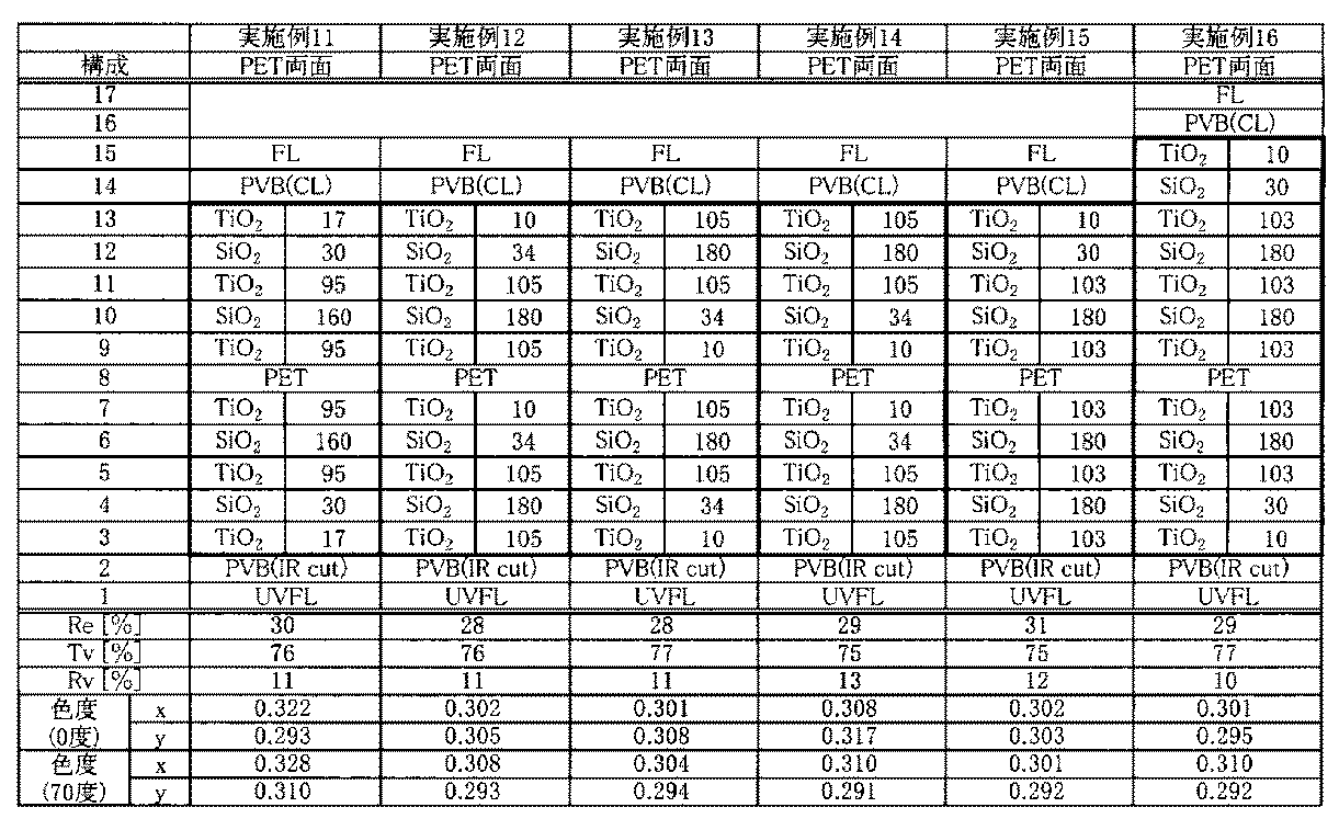
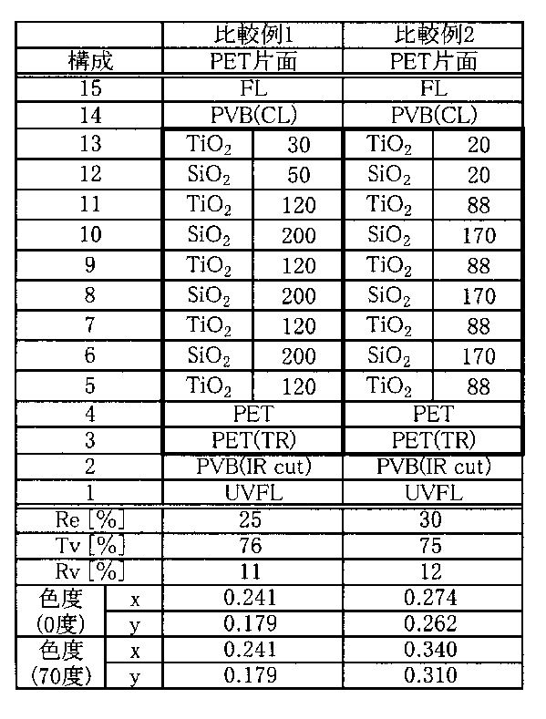

実施例の合わせガラスについては、いずれも表面の色度がx=0.31±0.02、y=0.31±0.02の範囲内となり、実用上問題のない色調を示した。一方、比較例の合わせガラスについては、表面の色度がx=0.31±0.02、y=0.31±0.02の範囲外となり、刺激色を帯びるために実用上好ましくないことが認められた。
本発明の赤外線反射基板によれば、高屈折率の誘電体膜と低屈折率の誘電体膜とを特有な厚さの組み合わせで繰り返して積層せることによって、合わせガラスとしたときにその表面が刺激色を帯びない良好な中間的色調となる合わせガラスを提供することができ、自動車、その他各種の車両の窓ガラス用、特にフロント窓ガラスとして、有用である。
なお、2010年7月16日に出願された日本特許出願2010-161275号の明細書、特許請求の範囲、図面および要約書の全内容をここに引用し、本発明の開示として取り入れるものである。
なお、2010年7月16日に出願された日本特許出願2010-161275号の明細書、特許請求の範囲、図面および要約書の全内容をここに引用し、本発明の開示として取り入れるものである。
1…赤外線反射基板
2…透明基材
3、4、5…赤外線反射膜
3H、4H、5H…高屈折率の誘電体膜
3L、4L、5L…低屈折率の誘電体膜
31、41、51…第1の積層部
32、42、52…第2の積層部
311、411、511…n・d/λ値が0.44~0.55である誘電体膜
321、421、521…n・d/λ値が0.03~0.12である誘電体膜
11…合わせガラス
12、13…ガラス基板
14、15…接着層
2…透明基材
3、4、5…赤外線反射膜
3H、4H、5H…高屈折率の誘電体膜
3L、4L、5L…低屈折率の誘電体膜
31、41、51…第1の積層部
32、42、52…第2の積層部
311、411、511…n・d/λ値が0.44~0.55である誘電体膜
321、421、521…n・d/λ値が0.03~0.12である誘電体膜
11…合わせガラス
12、13…ガラス基板
14、15…接着層
Claims (13)
- 透明基板と、前記透明基板の一方の主面に設けられ、高屈折率の誘電体膜と低屈折率の誘電体膜とが交互に7層以上積層されてなる赤外線反射膜とを有する赤外線反射基板であって、
前記赤外線反射膜は、厚さをd[nm]、波長がλ[nm]のときの屈折率をnとしたとき、n・d/λ値が0.44~0.55である高屈折率の誘電体膜と低屈折率の誘電体膜とが5層以上連続して積層されてなる第1の積層部と、n・d/λ値が0.03~0.12である高屈折率の誘電体膜と低屈折率の誘電体膜とが少なくとも2層連続して積層されてなる第2の積層部とを有することを特徴とする赤外線反射基板。 - 透明基板と、前記透明基板の一方の主面に設けられ、高屈折率の誘電体膜と低屈折率の誘電体膜とが交互に5層以上積層されてなる第1の赤外線反射膜と、前記透明基板の他方の主面に設けられ、高屈折率の誘電体膜と低屈折率の誘電体膜とが交互に5層以上積層されてなる第2の赤外線反射膜とを有する赤外線反射基板であって、
前記第1の赤外線反射膜、前記第2の赤外線反射膜の少なくとも一方は、厚さをd[nm]、波長がλ[nm]のときの屈折率をnとしたとき、n・d/λ値が0.44~0.55である高屈折率の誘電体膜と低屈折率の誘電体膜とが3層以上連続して積層されてなる第1の積層部と、n・d/λ値が0.03~0.12である高屈折率の誘電体膜と低屈折率の誘電体膜とが少なくとも2層連続して積層されてなる第2の積層部とを有することを特徴とする赤外線反射基板。 - 前記第1の積層部における高屈折率の誘電体膜の厚さが90~115nm、低屈折率の誘電体膜の厚さが150~195nmであることを特徴とする請求項1または2に記載の赤外線反射基板。
- 前記第2の積層部における高屈折率の誘電体膜の厚さが5~30nm、低屈折率の誘電体膜の厚さが10~50nmであることを特徴とする請求項1乃至3のいずれか1項に記載の赤外線反射基板。
- 前記高屈折率の誘電体膜は酸化チタンからなり、前記低屈折率の誘電体膜は酸化シリコンまたはフッ化マグネシウムからなることを特徴とする請求項1乃至4のいずれか1項に記載の赤外線反射基板。
- 対向する一対のガラス基板と、前記一対のガラス基板間に配置される赤外線反射基板と、前記一対のガラス基板と前記赤外線反射基板との間に配置される一対の接着層とを有する合わせガラスであって、
前記赤外線反射基板が請求項1乃至5のいずれか1項に記載の赤外線反射基板であって、かつその透明基板が樹脂フィルムからなることを特徴とする合わせガラス。 - 前記一対のガラス基板のうち前記赤外線反射基板の光線出射側となるガラス基板はUVグリーンガラス板であり、前記一対の接着層のうち前記赤外線反射基板の光線出射側となる接着層は赤外線遮蔽性剤を含有するものであることを特徴とする請求項6記載の合わせガラス。
- 一方の主面のみに赤外線反射膜を有する赤外線反射基板と、前記赤外線反射基板の前記赤外線反射膜側に対向して配置されるガラス基板と、前記赤外線反射基板と前記ガラス基板との間に配置される接着層とを有する合わせガラスであって、
前記赤外線反射基板が請求項1乃至5のいずれか1項に記載の赤外線反射基板であって、かつその透明基板がガラス板からなることを特徴とする合わせガラス。 - 光線出射側に前記赤外線反射基板が配置されるものであって、前記赤外線反射基板のガラス板がUVグリーンガラス板であることを特徴とする請求項8記載の合わせガラス。
- 光線入射側に前記赤外線反射基板が配置されるものであって、前記ガラス基板がUVグリーンガラス板であり、前記接着層が赤外線遮蔽性剤を含有するものであることを特徴とする請求項8記載の合わせガラス。
- 前記合わせガラスは、表面への光線入射角を0度としたとき、前記表面のJIS Z8701に規定される色度座標に従った色度がx=0.31±0.02、y=0.31±0.02の範囲内にあることを特徴とする請求項6乃至10のいずれか1項記載の合わせガラス。
- 前記光線入射角を70度としたとき、前記色度がx=0.31±0.02、y=0.31±0.02の範囲内にあることを特徴とする請求項11記載の合わせガラス。
- 前記合わせガラスの表面への光線入射角を0度としたとき、前記表面のJIS Z8701に規定される色度座標に従った色度がx=0.31±0.02、y=0.31±0.02の範囲内にあり、前記光線入射角を70度としたとき、前記色度がx=0.31±0.02、y=0.31±0.02の範囲内にある請求項6乃至10のいずれか1項に記載の合わせガラスからなる車両用ガラス。
Priority Applications (2)
| Application Number | Priority Date | Filing Date | Title |
|---|---|---|---|
| JP2012524616A JPWO2012008587A1 (ja) | 2010-07-16 | 2011-07-15 | 赤外線反射基板および合わせガラス |
| US13/741,429 US20130128342A1 (en) | 2010-07-16 | 2013-01-15 | Infrared reflecting substrate and laminated glass |
Applications Claiming Priority (2)
| Application Number | Priority Date | Filing Date | Title |
|---|---|---|---|
| JP2010-161275 | 2010-07-16 | ||
| JP2010161275 | 2010-07-16 |
Related Child Applications (1)
| Application Number | Title | Priority Date | Filing Date |
|---|---|---|---|
| US13/741,429 Continuation US20130128342A1 (en) | 2010-07-16 | 2013-01-15 | Infrared reflecting substrate and laminated glass |
Publications (1)
| Publication Number | Publication Date |
|---|---|
| WO2012008587A1 true WO2012008587A1 (ja) | 2012-01-19 |
Family
ID=45469581
Family Applications (1)
| Application Number | Title | Priority Date | Filing Date |
|---|---|---|---|
| PCT/JP2011/066257 Ceased WO2012008587A1 (ja) | 2010-07-16 | 2011-07-15 | 赤外線反射基板および合わせガラス |
Country Status (3)
| Country | Link |
|---|---|
| US (1) | US20130128342A1 (ja) |
| JP (1) | JPWO2012008587A1 (ja) |
| WO (1) | WO2012008587A1 (ja) |
Cited By (12)
| Publication number | Priority date | Publication date | Assignee | Title |
|---|---|---|---|---|
| WO2013137288A1 (ja) * | 2012-03-16 | 2013-09-19 | 東レ株式会社 | 多層積層フィルム |
| JP2013203574A (ja) * | 2012-03-28 | 2013-10-07 | Sumitomo Metal Mining Co Ltd | 熱線遮蔽膜、熱線遮蔽合わせ透明基材、および、当該熱線遮蔽合わせ透明基材が窓材として搭載されている自動車 |
| CN104297817A (zh) * | 2013-11-28 | 2015-01-21 | 中国航空工业集团公司洛阳电光设备研究所 | 一种具有激光高反射率、红外光高透射率的膜系及制备方法 |
| WO2015104981A1 (ja) * | 2014-01-09 | 2015-07-16 | コニカミノルタ株式会社 | 赤外線反射フィルム、赤外線反射フィルムの製造方法及び合わせガラスの製造方法 |
| JP2015145956A (ja) * | 2014-02-03 | 2015-08-13 | 京セラクリスタルデバイス株式会社 | 光学フィルタおよびその製造方法 |
| US20160271910A1 (en) * | 2013-04-02 | 2016-09-22 | Konica Minolta, Inc. | Heat ray shielding laminated glass and manufacturing method for heat ray shielding laminated glass |
| JP2016212340A (ja) * | 2015-05-13 | 2016-12-15 | 旭硝子株式会社 | 近赤外線カットフィルタ |
| CN106918905A (zh) * | 2017-02-24 | 2017-07-04 | 华为技术有限公司 | 光学部件和智能终端 |
| CN108726890A (zh) * | 2018-07-31 | 2018-11-02 | 吴江南玻华东工程玻璃有限公司 | 高透过率可单片使用的镀膜玻璃 |
| WO2018216595A1 (ja) * | 2017-05-25 | 2018-11-29 | 住友金属鉱山株式会社 | 近赤外線遮蔽超微粒子分散体、近赤外線遮蔽中間膜、近赤外線遮蔽合わせ構造体、および近赤外線遮蔽超微粒子分散体の製造方法 |
| CN109031492A (zh) * | 2013-12-26 | 2018-12-18 | Agc株式会社 | 滤光器 |
| US20210197531A1 (en) * | 2014-01-31 | 2021-07-01 | Sekisui Chemical Co., Ltd. | Intermediate film for laminated glass, laminated glass and method for fitting laminated glass |
Families Citing this family (29)
| Publication number | Priority date | Publication date | Assignee | Title |
|---|---|---|---|---|
| CN102976637B (zh) * | 2006-05-12 | 2016-03-30 | 积水化学工业株式会社 | 夹层玻璃用中间膜及夹层玻璃 |
| US11599003B2 (en) | 2011-09-30 | 2023-03-07 | View, Inc. | Fabrication of electrochromic devices |
| US9007674B2 (en) | 2011-09-30 | 2015-04-14 | View, Inc. | Defect-mitigation layers in electrochromic devices |
| US12496809B2 (en) | 2010-11-08 | 2025-12-16 | View Operating Corporation | Electrochromic window fabrication methods |
| US12403676B2 (en) | 2011-12-12 | 2025-09-02 | View Operating Corporation | Thin-film devices and fabrication |
| US11865632B2 (en) | 2011-12-12 | 2024-01-09 | View, Inc. | Thin-film devices and fabrication |
| US12061402B2 (en) | 2011-12-12 | 2024-08-13 | View, Inc. | Narrow pre-deposition laser deletion |
| US10802371B2 (en) | 2011-12-12 | 2020-10-13 | View, Inc. | Thin-film devices and fabrication |
| CN103454709A (zh) * | 2012-05-30 | 2013-12-18 | 鸿富锦精密工业(深圳)有限公司 | 红外截止滤光片及镜头模组 |
| US9594195B2 (en) | 2013-02-13 | 2017-03-14 | Centre Luxembourgeois de Recherches Pour le Verre et la Ceramique (CRVC) SaRL | Dielectric mirror |
| US9977157B2 (en) * | 2013-02-13 | 2018-05-22 | Guardian Europe S.à r.l. | Dielectric mirror |
| US9684097B2 (en) | 2013-05-07 | 2017-06-20 | Corning Incorporated | Scratch-resistant articles with retained optical properties |
| US9366784B2 (en) | 2013-05-07 | 2016-06-14 | Corning Incorporated | Low-color scratch-resistant articles with a multilayer optical film |
| US9110230B2 (en) | 2013-05-07 | 2015-08-18 | Corning Incorporated | Scratch-resistant articles with retained optical properties |
| US9703011B2 (en) | 2013-05-07 | 2017-07-11 | Corning Incorporated | Scratch-resistant articles with a gradient layer |
| US9359261B2 (en) * | 2013-05-07 | 2016-06-07 | Corning Incorporated | Low-color scratch-resistant articles with a multilayer optical film |
| US11267973B2 (en) | 2014-05-12 | 2022-03-08 | Corning Incorporated | Durable anti-reflective articles |
| US9335444B2 (en) | 2014-05-12 | 2016-05-10 | Corning Incorporated | Durable and scratch-resistant anti-reflective articles |
| US9611999B2 (en) * | 2014-07-21 | 2017-04-04 | GE Lighting Solutions, LLC | Reflecting apparatus including enhanced aluminum optical coatings |
| US9790593B2 (en) | 2014-08-01 | 2017-10-17 | Corning Incorporated | Scratch-resistant materials and articles including the same |
| US12235560B2 (en) | 2014-11-25 | 2025-02-25 | View, Inc. | Faster switching electrochromic devices |
| US10730790B2 (en) * | 2015-02-25 | 2020-08-04 | Corning Incorporated | Optical structures and articles with multilayer stacks having high hardness and methods for making the same |
| CN107533267A (zh) | 2015-03-20 | 2018-01-02 | 唯景公司 | 更快速地切换低缺陷电致变色窗 |
| JP2018536177A (ja) | 2015-09-14 | 2018-12-06 | コーニング インコーポレイテッド | 高光線透過性かつ耐擦傷性反射防止物品 |
| US11143800B2 (en) * | 2017-06-16 | 2021-10-12 | Corning Incorporated | Extending the reflection bandwith of silver coating stacks for highly reflective mirrors |
| WO2019230732A1 (ja) * | 2018-05-30 | 2019-12-05 | Agc株式会社 | 合わせガラス |
| CN114085038A (zh) | 2018-08-17 | 2022-02-25 | 康宁股份有限公司 | 具有薄的耐久性减反射结构的无机氧化物制品 |
| US11004612B2 (en) * | 2019-03-14 | 2021-05-11 | MicroSol Technologies Inc. | Low temperature sub-nanometer periodic stack dielectrics |
| US12386101B2 (en) | 2020-07-09 | 2025-08-12 | Corning Incorporated | Textured region of a substrate to reduce specular reflectance incorporating surface features with an elliptical perimeter or segments thereof, and method of making the same |
Citations (6)
| Publication number | Priority date | Publication date | Assignee | Title |
|---|---|---|---|---|
| JPS57181503A (en) * | 1981-04-30 | 1982-11-09 | Nippon Soken Inc | Heat ray reflecting film |
| JP2004155632A (ja) * | 2002-11-08 | 2004-06-03 | Nippon Sheet Glass Co Ltd | 熱遮蔽膜、それを用いた熱遮蔽ガラス板、および熱遮蔽合わせガラス板 |
| WO2007020791A1 (ja) * | 2005-08-16 | 2007-02-22 | Asahi Glass Company, Limited | 車両窓用合わせガラス |
| JP2007065232A (ja) * | 2005-08-31 | 2007-03-15 | National Institute Of Advanced Industrial & Technology | 紫外線熱線反射多層膜 |
| WO2008152887A1 (ja) * | 2007-06-11 | 2008-12-18 | National Institute Of Advanced Industrial Science And Technology | 可視光透過日射熱反射膜 |
| JP2010078714A (ja) * | 2008-09-24 | 2010-04-08 | Panasonic Electric Works Co Ltd | 広域熱線カットフィルタ |
Family Cites Families (2)
| Publication number | Priority date | Publication date | Assignee | Title |
|---|---|---|---|---|
| US6049419A (en) * | 1998-01-13 | 2000-04-11 | 3M Innovative Properties Co | Multilayer infrared reflecting optical body |
| WO2007020792A1 (ja) * | 2005-08-16 | 2007-02-22 | Asahi Glass Company, Limited | 赤外線反射ガラス板および車両窓用合わせガラス |
-
2011
- 2011-07-15 JP JP2012524616A patent/JPWO2012008587A1/ja not_active Withdrawn
- 2011-07-15 WO PCT/JP2011/066257 patent/WO2012008587A1/ja not_active Ceased
-
2013
- 2013-01-15 US US13/741,429 patent/US20130128342A1/en not_active Abandoned
Patent Citations (6)
| Publication number | Priority date | Publication date | Assignee | Title |
|---|---|---|---|---|
| JPS57181503A (en) * | 1981-04-30 | 1982-11-09 | Nippon Soken Inc | Heat ray reflecting film |
| JP2004155632A (ja) * | 2002-11-08 | 2004-06-03 | Nippon Sheet Glass Co Ltd | 熱遮蔽膜、それを用いた熱遮蔽ガラス板、および熱遮蔽合わせガラス板 |
| WO2007020791A1 (ja) * | 2005-08-16 | 2007-02-22 | Asahi Glass Company, Limited | 車両窓用合わせガラス |
| JP2007065232A (ja) * | 2005-08-31 | 2007-03-15 | National Institute Of Advanced Industrial & Technology | 紫外線熱線反射多層膜 |
| WO2008152887A1 (ja) * | 2007-06-11 | 2008-12-18 | National Institute Of Advanced Industrial Science And Technology | 可視光透過日射熱反射膜 |
| JP2010078714A (ja) * | 2008-09-24 | 2010-04-08 | Panasonic Electric Works Co Ltd | 広域熱線カットフィルタ |
Cited By (24)
| Publication number | Priority date | Publication date | Assignee | Title |
|---|---|---|---|---|
| KR20140141635A (ko) * | 2012-03-16 | 2014-12-10 | 도레이 카부시키가이샤 | 다층 적층 필름 |
| WO2013137288A1 (ja) * | 2012-03-16 | 2013-09-19 | 東レ株式会社 | 多層積層フィルム |
| KR102053671B1 (ko) | 2012-03-16 | 2019-12-09 | 도레이 카부시키가이샤 | 다층 적층 필름 |
| US9527266B2 (en) | 2012-03-16 | 2016-12-27 | Toray Industries, Inc. | Multi-layer laminated film |
| JP2013203574A (ja) * | 2012-03-28 | 2013-10-07 | Sumitomo Metal Mining Co Ltd | 熱線遮蔽膜、熱線遮蔽合わせ透明基材、および、当該熱線遮蔽合わせ透明基材が窓材として搭載されている自動車 |
| US20160271910A1 (en) * | 2013-04-02 | 2016-09-22 | Konica Minolta, Inc. | Heat ray shielding laminated glass and manufacturing method for heat ray shielding laminated glass |
| CN104297817A (zh) * | 2013-11-28 | 2015-01-21 | 中国航空工业集团公司洛阳电光设备研究所 | 一种具有激光高反射率、红外光高透射率的膜系及制备方法 |
| CN104297817B (zh) * | 2013-11-28 | 2016-02-10 | 中国航空工业集团公司洛阳电光设备研究所 | 一种具有激光高反射率、红外光高透射率的膜系及制备方法 |
| CN109031492A (zh) * | 2013-12-26 | 2018-12-18 | Agc株式会社 | 滤光器 |
| WO2015104981A1 (ja) * | 2014-01-09 | 2015-07-16 | コニカミノルタ株式会社 | 赤外線反射フィルム、赤外線反射フィルムの製造方法及び合わせガラスの製造方法 |
| US20210197531A1 (en) * | 2014-01-31 | 2021-07-01 | Sekisui Chemical Co., Ltd. | Intermediate film for laminated glass, laminated glass and method for fitting laminated glass |
| US12311636B2 (en) | 2014-01-31 | 2025-05-27 | Sekisui Chemical Co., Ltd. | Intermediate film for laminated glass, laminated glass and method for fitting laminated glass |
| US11524487B2 (en) | 2014-01-31 | 2022-12-13 | Sekisui Chemical Co., Ltd. | Laminated glass and method for fitting laminated glass |
| JP2015145956A (ja) * | 2014-02-03 | 2015-08-13 | 京セラクリスタルデバイス株式会社 | 光学フィルタおよびその製造方法 |
| JP2016212340A (ja) * | 2015-05-13 | 2016-12-15 | 旭硝子株式会社 | 近赤外線カットフィルタ |
| CN106918905A (zh) * | 2017-02-24 | 2017-07-04 | 华为技术有限公司 | 光学部件和智能终端 |
| CN106918905B (zh) * | 2017-02-24 | 2019-10-18 | 华为技术有限公司 | 光学部件和智能终端 |
| JP2018199758A (ja) * | 2017-05-25 | 2018-12-20 | 住友金属鉱山株式会社 | 近赤外線遮蔽超微粒子分散体、近赤外線遮蔽中間膜、近赤外線遮蔽合わせ構造体、および近赤外線遮蔽超微粒子分散体の製造方法 |
| KR20200014285A (ko) * | 2017-05-25 | 2020-02-10 | 스미토모 긴조쿠 고잔 가부시키가이샤 | 근적외선 차폐 초미립자 분산체, 근적외선 차폐 중간막, 근적외선 차폐 접합 구조체, 및 근적외선 차폐 초미립자 분산체의 제조 방법 |
| KR102466871B1 (ko) | 2017-05-25 | 2022-11-15 | 스미토모 긴조쿠 고잔 가부시키가이샤 | 근적외선 차폐 초미립자 분산체, 근적외선 차폐 중간막, 근적외선 차폐 접합 구조체, 및 근적외선 차폐 초미립자 분산체의 제조 방법 |
| US11884790B2 (en) | 2017-05-25 | 2024-01-30 | Sumitomo Metal Mining Co., Ltd. | Near-infrared shielding ultrafine particle dispersion body, near-infrared shielding intermediate film, near-infrared shielding laminated structure, and method for producing near-infrared shielding ultrafine particle dispersion body |
| WO2018216595A1 (ja) * | 2017-05-25 | 2018-11-29 | 住友金属鉱山株式会社 | 近赤外線遮蔽超微粒子分散体、近赤外線遮蔽中間膜、近赤外線遮蔽合わせ構造体、および近赤外線遮蔽超微粒子分散体の製造方法 |
| CN108726890A (zh) * | 2018-07-31 | 2018-11-02 | 吴江南玻华东工程玻璃有限公司 | 高透过率可单片使用的镀膜玻璃 |
| CN108726890B (zh) * | 2018-07-31 | 2024-02-23 | 吴江南玻华东工程玻璃有限公司 | 高透过率可单片使用的镀膜玻璃 |
Also Published As
| Publication number | Publication date |
|---|---|
| US20130128342A1 (en) | 2013-05-23 |
| JPWO2012008587A1 (ja) | 2013-09-09 |
Similar Documents
| Publication | Publication Date | Title |
|---|---|---|
| JPWO2012008587A1 (ja) | 赤外線反射基板および合わせガラス | |
| JP7722925B2 (ja) | 低い可視光反射率を有するヘッドアップディスプレイのためのコーティング | |
| CN101243022B (zh) | 红外线反射玻璃板及车窗用夹层玻璃 | |
| US7638184B2 (en) | Laminated glass for vehicle window | |
| JP5809132B2 (ja) | 透明積層ガラスおよびその使用法 | |
| JP5675356B2 (ja) | 車両用透明物 | |
| WO2010119797A1 (ja) | 自動車ガラス用積層体、その製造方法、およびフロントガラス | |
| US20130302580A1 (en) | Laminated glass and process for producing laminated glass | |
| KR20120048536A (ko) | 차량용 합판 유리 | |
| JP2015003388A (ja) | ガラス積層体 | |
| JP2011195417A (ja) | 合わせガラス | |
| JP2008037667A (ja) | 窓用合わせガラス | |
| JP2023115054A (ja) | 車両用ドアガラス | |
| CN101288007A (zh) | 近红外线反射基板和利用该基板的近红外线反射层叠玻璃、近红外线反射双层玻璃 | |
| JP6549044B2 (ja) | 自動車用遮熱合わせガラス | |
| JP2025502529A (ja) | 薄層の機能性スタックを提供される透明基材 | |
| JP2009536607A (ja) | 美的透明部品 | |
| WO2012169603A1 (ja) | 光学膜および合わせガラス | |
| JP5413314B2 (ja) | 赤外線反射フィルムおよび合わせガラスの製造方法 | |
| WO2012157385A1 (ja) | 合わせガラス | |
| KR20220057668A (ko) | 접합 유리용 중간막 및 접합 유리 | |
| WO2011055685A1 (ja) | 合わせガラスの製造方法 | |
| US20230358937A1 (en) | Laminated glazing with reduced outside light reflection and head-up display with improved visibility | |
| JP2011195416A (ja) | 合わせガラスの製造方法 | |
| JP2011144061A (ja) | 合わせガラス |
Legal Events
| Date | Code | Title | Description |
|---|---|---|---|
| 121 | Ep: the epo has been informed by wipo that ep was designated in this application |
Ref document number: 11806917 Country of ref document: EP Kind code of ref document: A1 |
|
| WWE | Wipo information: entry into national phase |
Ref document number: 2012524616 Country of ref document: JP |
|
| NENP | Non-entry into the national phase |
Ref country code: DE |
|
| 122 | Ep: pct application non-entry in european phase |
Ref document number: 11806917 Country of ref document: EP Kind code of ref document: A1 |