WO2012002207A1 - Procédé et appareil de formation d'image à polarisation - Google Patents
Procédé et appareil de formation d'image à polarisation Download PDFInfo
- Publication number
- WO2012002207A1 WO2012002207A1 PCT/JP2011/064228 JP2011064228W WO2012002207A1 WO 2012002207 A1 WO2012002207 A1 WO 2012002207A1 JP 2011064228 W JP2011064228 W JP 2011064228W WO 2012002207 A1 WO2012002207 A1 WO 2012002207A1
- Authority
- WO
- WIPO (PCT)
- Prior art keywords
- polarization
- light
- image
- interference
- reference light
- Prior art date
Links
- 230000010287 polarization Effects 0.000 title claims abstract description 783
- 238000003384 imaging method Methods 0.000 title claims abstract description 472
- 238000000034 method Methods 0.000 title description 78
- 238000009826 distribution Methods 0.000 claims abstract description 165
- 230000010363 phase shift Effects 0.000 claims description 247
- 230000003287 optical effect Effects 0.000 claims description 135
- 238000004364 calculation method Methods 0.000 claims description 42
- 239000000284 extract Substances 0.000 claims description 22
- NCGICGYLBXGBGN-UHFFFAOYSA-N 3-morpholin-4-yl-1-oxa-3-azonia-2-azanidacyclopent-3-en-5-imine;hydrochloride Chemical compound Cl.[N-]1OC(=N)C=[N+]1N1CCOCC1 NCGICGYLBXGBGN-UHFFFAOYSA-N 0.000 claims description 15
- 230000008859 change Effects 0.000 claims description 10
- 230000002452 interceptive effect Effects 0.000 claims description 5
- 238000006243 chemical reaction Methods 0.000 claims description 4
- 238000010586 diagram Methods 0.000 description 81
- 238000004088 simulation Methods 0.000 description 22
- 238000004422 calculation algorithm Methods 0.000 description 16
- 230000003595 spectral effect Effects 0.000 description 16
- 238000012545 processing Methods 0.000 description 12
- 238000001914 filtration Methods 0.000 description 11
- 238000001093 holography Methods 0.000 description 9
- 238000001228 spectrum Methods 0.000 description 9
- 230000006870 function Effects 0.000 description 6
- 239000011159 matrix material Substances 0.000 description 5
- 239000013598 vector Substances 0.000 description 5
- 238000000701 chemical imaging Methods 0.000 description 4
- 238000012937 correction Methods 0.000 description 4
- 230000003111 delayed effect Effects 0.000 description 4
- 239000011521 glass Substances 0.000 description 4
- 238000005259 measurement Methods 0.000 description 4
- 238000004458 analytical method Methods 0.000 description 3
- 230000008878 coupling Effects 0.000 description 3
- 238000010168 coupling process Methods 0.000 description 3
- 238000005859 coupling reaction Methods 0.000 description 3
- 238000005516 engineering process Methods 0.000 description 3
- 239000000463 material Substances 0.000 description 3
- 238000004611 spectroscopical analysis Methods 0.000 description 3
- XUIMIQQOPSSXEZ-UHFFFAOYSA-N Silicon Chemical compound [Si] XUIMIQQOPSSXEZ-UHFFFAOYSA-N 0.000 description 2
- 230000009471 action Effects 0.000 description 2
- 230000008901 benefit Effects 0.000 description 2
- 230000000903 blocking effect Effects 0.000 description 2
- 239000000969 carrier Substances 0.000 description 2
- 238000005094 computer simulation Methods 0.000 description 2
- 230000007423 decrease Effects 0.000 description 2
- 230000000694 effects Effects 0.000 description 2
- 239000010408 film Substances 0.000 description 2
- 238000007689 inspection Methods 0.000 description 2
- 230000010354 integration Effects 0.000 description 2
- 239000004973 liquid crystal related substance Substances 0.000 description 2
- 102000004169 proteins and genes Human genes 0.000 description 2
- 108090000623 proteins and genes Proteins 0.000 description 2
- 229910052710 silicon Inorganic materials 0.000 description 2
- 239000010703 silicon Substances 0.000 description 2
- 238000012800 visualization Methods 0.000 description 2
- 102000008186 Collagen Human genes 0.000 description 1
- 108010035532 Collagen Proteins 0.000 description 1
- 241000282326 Felis catus Species 0.000 description 1
- 206010028980 Neoplasm Diseases 0.000 description 1
- 238000010521 absorption reaction Methods 0.000 description 1
- 230000004075 alteration Effects 0.000 description 1
- 239000012472 biological sample Substances 0.000 description 1
- 230000005540 biological transmission Effects 0.000 description 1
- 230000015572 biosynthetic process Effects 0.000 description 1
- 201000011510 cancer Diseases 0.000 description 1
- 238000012512 characterization method Methods 0.000 description 1
- 230000001427 coherent effect Effects 0.000 description 1
- 229920001436 collagen Polymers 0.000 description 1
- 238000004040 coloring Methods 0.000 description 1
- 230000006866 deterioration Effects 0.000 description 1
- 238000011156 evaluation Methods 0.000 description 1
- 230000014509 gene expression Effects 0.000 description 1
- 229910052500 inorganic mineral Inorganic materials 0.000 description 1
- 229920002521 macromolecule Polymers 0.000 description 1
- 238000004519 manufacturing process Methods 0.000 description 1
- 239000002207 metabolite Substances 0.000 description 1
- 239000011707 mineral Substances 0.000 description 1
- 239000000203 mixture Substances 0.000 description 1
- 238000012986 modification Methods 0.000 description 1
- 230000004048 modification Effects 0.000 description 1
- 238000000465 moulding Methods 0.000 description 1
- 238000010422 painting Methods 0.000 description 1
- 230000001575 pathological effect Effects 0.000 description 1
- 239000004038 photonic crystal Substances 0.000 description 1
- 238000000053 physical method Methods 0.000 description 1
- 230000008569 process Effects 0.000 description 1
- 230000008929 regeneration Effects 0.000 description 1
- 238000011069 regeneration method Methods 0.000 description 1
- 230000004044 response Effects 0.000 description 1
- 230000007480 spreading Effects 0.000 description 1
- 238000003892 spreading Methods 0.000 description 1
- 238000010186 staining Methods 0.000 description 1
- 239000000126 substance Substances 0.000 description 1
- 239000010409 thin film Substances 0.000 description 1
- 238000002834 transmittance Methods 0.000 description 1
- 235000012431 wafers Nutrition 0.000 description 1
Images


Classifications
-
- H—ELECTRICITY
- H04—ELECTRIC COMMUNICATION TECHNIQUE
- H04N—PICTORIAL COMMUNICATION, e.g. TELEVISION
- H04N23/00—Cameras or camera modules comprising electronic image sensors; Control thereof
- H04N23/56—Cameras or camera modules comprising electronic image sensors; Control thereof provided with illuminating means
-
- G—PHYSICS
- G01—MEASURING; TESTING
- G01N—INVESTIGATING OR ANALYSING MATERIALS BY DETERMINING THEIR CHEMICAL OR PHYSICAL PROPERTIES
- G01N21/00—Investigating or analysing materials by the use of optical means, i.e. using sub-millimetre waves, infrared, visible or ultraviolet light
- G01N21/17—Systems in which incident light is modified in accordance with the properties of the material investigated
- G01N21/21—Polarisation-affecting properties
-
- G—PHYSICS
- G03—PHOTOGRAPHY; CINEMATOGRAPHY; ANALOGOUS TECHNIQUES USING WAVES OTHER THAN OPTICAL WAVES; ELECTROGRAPHY; HOLOGRAPHY
- G03H—HOLOGRAPHIC PROCESSES OR APPARATUS
- G03H1/00—Holographic processes or apparatus using light, infrared or ultraviolet waves for obtaining holograms or for obtaining an image from them; Details peculiar thereto
- G03H1/04—Processes or apparatus for producing holograms
- G03H1/0443—Digital holography, i.e. recording holograms with digital recording means
-
- G—PHYSICS
- G01—MEASURING; TESTING
- G01N—INVESTIGATING OR ANALYSING MATERIALS BY DETERMINING THEIR CHEMICAL OR PHYSICAL PROPERTIES
- G01N21/00—Investigating or analysing materials by the use of optical means, i.e. using sub-millimetre waves, infrared, visible or ultraviolet light
- G01N21/17—Systems in which incident light is modified in accordance with the properties of the material investigated
- G01N2021/1765—Method using an image detector and processing of image signal
-
- G—PHYSICS
- G03—PHOTOGRAPHY; CINEMATOGRAPHY; ANALOGOUS TECHNIQUES USING WAVES OTHER THAN OPTICAL WAVES; ELECTROGRAPHY; HOLOGRAPHY
- G03H—HOLOGRAPHIC PROCESSES OR APPARATUS
- G03H1/00—Holographic processes or apparatus using light, infrared or ultraviolet waves for obtaining holograms or for obtaining an image from them; Details peculiar thereto
- G03H1/04—Processes or apparatus for producing holograms
- G03H1/0443—Digital holography, i.e. recording holograms with digital recording means
- G03H2001/0454—Arrangement for recovering hologram complex amplitude
- G03H2001/0458—Temporal or spatial phase shifting, e.g. parallel phase shifting method
-
- G—PHYSICS
- G03—PHOTOGRAPHY; CINEMATOGRAPHY; ANALOGOUS TECHNIQUES USING WAVES OTHER THAN OPTICAL WAVES; ELECTROGRAPHY; HOLOGRAPHY
- G03H—HOLOGRAPHIC PROCESSES OR APPARATUS
- G03H1/00—Holographic processes or apparatus using light, infrared or ultraviolet waves for obtaining holograms or for obtaining an image from them; Details peculiar thereto
- G03H1/22—Processes or apparatus for obtaining an optical image from holograms
- G03H1/2249—Holobject properties
- G03H2001/2276—Polarisation dependent holobject
-
- G—PHYSICS
- G03—PHOTOGRAPHY; CINEMATOGRAPHY; ANALOGOUS TECHNIQUES USING WAVES OTHER THAN OPTICAL WAVES; ELECTROGRAPHY; HOLOGRAPHY
- G03H—HOLOGRAPHIC PROCESSES OR APPARATUS
- G03H2222/00—Light sources or light beam properties
- G03H2222/31—Polarised light
Definitions
- the present invention relates to a polarization imaging apparatus and a polarization imaging method for performing polarization imaging of a subject.
- the unit of phase is expressed in radians.
- a polarization imaging camera that simultaneously acquires polarization information in a plurality of directions has been developed, a polarization imaging apparatus that visualizes the polarization distribution of a subject (Patent Document 1), and a polarization microscope that visualizes the polarization distribution of a subject (Patent Document 2) has been proposed.
- polarization imaging As an application of polarization imaging, measurement of structure / strain of film or glass used in window materials, show windows, displays, etc., measurement of film pressure and strain in thin films of solar cells, application of polarization microscope, A wide variety of applications are conceivable, including molecular structure characterization, identification of rock-forming minerals, visualization of the internal structure of living organisms (cells) without staining, and visualization of the distribution of proteins or collagen in living cells.
- Non-Patent Document 1 describes a technique for performing polarization imaging using off-axis type digital holography.
- off-axis type digital holography object light and reference light are incident on the image sensor at different angles. Therefore, when the hologram is reproduced, the 0th-order diffracted light and the conjugate image ( ⁇ 1st-order diffracted light) do not overlap with the object image (first-order diffracted light), and only a desired object image can be obtained.
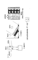
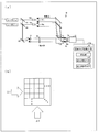
- FIG. 53 is a diagram showing a configuration of a conventional polarization imaging apparatus shown in Non-Patent Document 1.
- FIG. 54 is a diagram showing the relationship between the object light incident on the imaging device provided in the polarization imaging apparatus shown in FIG. 53 and the reference lights R1 and R2.
- the reference beams R1 and R2 having components of different polarization directions P1 and P2 are made to have different angles with respect to the object beam from different directions (for convenience of explanation, ⁇ 1, ⁇ 2 ) and an interference image (hologram) is obtained.
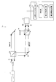
- FIG. 55 is a diagram for explaining a procedure for reproducing an image from a hologram recorded in the polarization imaging apparatus.
- the obtained interference image is Fourier transformed, and the spatial spectral distribution is obtained by calculation.
- Information on the spatial spectrum of the subject in each of the polarization directions P1 and P2 is extracted. Thereafter, the information of the subject in each polarization direction is phase-corrected by an amount related to the angles ⁇ 1 and ⁇ 2 , subjected to inverse Fourier transform, and an image is reproduced by diffraction calculation.
- polarization imaging is performed using the complex amplitude distribution of the subject in the polarization directions P1 and P2.
- Non-Patent Document 2 describes a technique for performing polarization imaging using in-line type (in-line type or on-axis type) digital holography.
- in-line type digital holography the object light and the reference light are incident on the image sensor at the same angle. For this reason, when the hologram is reproduced, the 0th-order diffracted light, which is a noise component, the conjugate image ( ⁇ 1st-order diffracted light), and the object image (first-order diffracted light) overlap.
- Japanese Patent Publication Japanese Patent Laid-Open No. 2007-086720 (published on April 5, 2007)”
- Japanese Patent Publication Japanese Patent Laid-Open No. 2008-032969 (published on Feb. 14, 2008)”
- Non-Patent Document 1 since the off-axis type digital holography is used, the imageable range (field of view) is narrow (in-line type in which holograms are spatially multiplexed and recorded in four divisions). Compared with a field of view of about 1/4, the image quality of the reproduced image reproduced from the hologram is not good, and the resolution of the reproduced image is low. Further, since the optical system becomes complicated, the apparatus becomes complicated and large when the hologram imaging optical system is made into one apparatus.
- Non-Patent Document 1 has a problem that the reference light incident angles ⁇ 1 and ⁇ 2 and the hardware or software for “phase correction” need to be adjusted with extremely high accuracy. . Therefore, the present inventors have found that there is a problem that the polarization imaging accuracy is easily lowered by a slight change in the position and angle of the optical element.
- Non-Patent Document 1 polarization imaging is performed by using subject amplitude information and phase difference information in different polarization directions P1 and P2.
- the phase difference information is subjected to phase modulation corresponding to the incident angles ⁇ 1 and ⁇ 2 of the reference light, and it is necessary to remove this phase modulation for accurate polarization imaging.
- To remove phase modulation first adjust the incident angle of the reference beam, then measure with high accuracy, and record the interference image and compare the correction amount obtained with the physical measurement value.
- the phase of the object light in each polarization direction must be corrected.
- Non-Patent Document 1 When phase correction is actually performed by a computer, the accuracy of the third decimal point, the fourth digit, or higher is required as the values of the incident angles ⁇ 1 and ⁇ 2 . In terms of physical angle adjustment, extremely high accuracy of about 0.006 [°] ( ⁇ 0.0001 [rad]) is required for an object 300 mm away. Furthermore, since such high-precision adjustment accuracy is required, the optical element (each BS (beam splitting element) in FIG. 53, each M (mirror) is vulnerable to an angular deviation between the object light and each reference light. ), Etc.) are slightly changed in angle and position, the phase difference information cannot be obtained accurately, and the accuracy of polarization imaging easily decreases.
- the configuration described in Non-Patent Document 1 has been demonstrated for a weakly scattered two-dimensional object having polarization dependency such as a wave plate, but has not been demonstrated for a strongly-scattered three-dimensional object. Is extremely difficult.
- FIG. 56 is a diagram for explaining problems of the polarization imaging apparatus described in Non-Patent Document 1.
- the spatial spectrum overlaps between the subject and an unnecessary image component, and an unnecessary image is superimposed on the reproduced image. There is a problem of being narrow.
- Non-Patent Document 1 when information on the fine structure of the subject is recorded, unnecessary image components are superimposed on the reproduced image. The resolution becomes lower. If an attempt is made to increase the resolution forcibly, an unnecessary image is superimposed. This means that the resolution cannot be increased when applied to a high-power microscope, and causes a problem that clear imaging of a fine structure becomes extremely difficult.
- the configuration described in Non-Patent Document 2 uses inline digital holography, and therefore has a wider shooting range than the configuration described in Non-Patent Document 1, and the image quality in a reproduced image is also high. good.
- the configuration described in Non-Patent Document 2 has a simpler optical system than the configuration described in Non-Patent Document 1, so the size of the device can be reduced when the hologram imaging optical system is a single device. Easy to do.
- Non-Patent Document 2 in order to obtain an object image, it is necessary to sequentially capture information on the intensity distribution of object light on the imaging element surface in a plurality of polarization directions.
- the present invention has been made in view of the above-described problems, and an object of the present invention is to obtain a wide range and detailed three-dimensional information and polarization distribution of a subject as well as spectral characteristics by one imaging.
- the object is to realize a polarization imaging apparatus of image quality.
- the three-dimensional information includes information on the three-dimensional shape, position, or distribution of the subject.
- a polarization imaging apparatus includes at least one light source that supplies reference light and object light, and an imaging unit, and captures the interference image formed by the reference light and object light that reaches through the subject.
- the object light incident on the imaging unit and the reference light incident on the imaging unit include polarized light in a first direction and polarized light in a second direction different from the first direction
- the imaging unit includes a first interference image formed by interference of the reference light having the first direction of polarization and the first phase with the object light, and the reference light having the first direction of polarization and the second phase.
- a second interference image formed by interfering with the object light a third interference image formed by interference of the reference light having the polarization in the second direction and the first phase with the object light, and the second direction.
- a reference beam having the second polarization and the second phase interferes with the object beam.
- An interference pattern including the fourth interference image is extracted at a time, and pixels corresponding to the first interference image and the second interference image are extracted from the interference pattern and interpolated, and then polarized in the first direction of the subject.
- Reproduction that generates a reproduction image of the component, extracts pixels corresponding to the third interference image and the fourth interference image from the interference pattern, interpolates, and then generates a reproduction image of the polarization component in the second direction of the subject Polarization for obtaining a polarized image at each position of the reproduced image of the subject based on an image generation unit, a reproduced image of the polarized component in the first direction of the subject, and a reproduced image of the polarized component in the second direction of the subject And an image calculation unit.
- a light source that supplies reference light and object light and an imaging unit are provided, and the reference light and the subject are interposed.
- the imaging unit captures an interference image formed by the object light that reaches the object light
- the object light incident on the imaging unit and the reference light incident on the imaging unit are polarized in a first direction and first
- the imaging unit includes a first interference image and a second interference image formed by two reference lights having different phases from each other with the object light with respect to the polarization component in the first direction.
- a total of four types of interference images including a third interference image and a fourth interference image formed by interference of two reference lights having different phases with the object light are included. Capture the interference pattern at once and After extracting and interpolating the pixels corresponding to the first interference image and the second interference image from the interference pattern, a reproduction image of the polarization component in the first direction of the subject is generated, and the third interference image is generated from the interference pattern.
- a pixel corresponding to the fourth interference image is extracted and interpolated, and then a reproduction image generation unit that generates a reproduction image of the polarization component in the second direction of the subject, and a reproduction image of the polarization component in the first direction of the subject And a polarization image calculation unit that obtains a polarization image at each position of the reproduction image of the subject based on the reproduction image of the polarization component in the second direction of the subject.
- the polarization imaging method is a polarization imaging method that obtains a polarization state of object light by capturing an interference image formed by reference light and object light reaching through a subject, and creates the interference image.
- the object light and the reference light that creates the interference image include polarized light in a first direction and polarized light in a second direction different from the first direction, and the reference light having the polarized light in the first direction and the first phase
- the reference light having the first phase interferes with the object light
- the reference light having the second direction of polarization and the second phase interferes with the object light.
- an interference image formed by the reference light and the object light reaching through the subject is captured, and the object light
- a polarization imaging method for obtaining a polarization state of the object wherein the object light that creates the interference image and the reference light that creates the interference image include polarization in a first direction and polarization in a second direction different from the first direction.
- the first reference image and the second interference image produced by the interference of the two reference lights having different phases with the object light with respect to the polarization component in the first direction and the polarization components in the second direction with different phases 2 A step of imaging an interference pattern including a third interference image and a fourth interference image formed by interference of two reference beams with object light at a time, and corresponding to the first interference image and the second interference image from the interference pattern Extract and interpolate pixels After that, a reproduction image of the polarization component in the first direction of the subject is generated, and pixels corresponding to the third interference image and the fourth interference image are extracted from the interference pattern and interpolated.
- the kind of interference image can be acquired at once, and a reproduction image for each polarization direction can be obtained by using the phase shift method. Based on this, the polarization state of the object light at each position of the reproduction image of the subject is obtained. Therefore, it is not necessary to perform imaging a plurality of times, and a wide range and detailed three-dimensional information and polarization distribution of the subject can be obtained by one imaging. Therefore, if the above configuration is used, it is possible to image, for example, a three-dimensional structure and polarization distribution at a certain moment of a subject with a dynamic change.
- the polarization distribution can be imaged. Further, spectral characteristics can be obtained by using a plurality of light sources.
- a polarization imaging apparatus includes a light source that supplies reference light and object light, and an imaging unit, and the imaging unit captures an interference image formed by the reference light and object light that reaches through the subject.
- the object light incident on the imaging unit and the reference light incident on the imaging unit include polarized light in a first direction and polarized light in a second direction different from the first direction
- the light source is Supplying light of at least one wavelength
- the imaging unit includes a first interference image formed by interference of the reference light having the polarization in the first direction and the first optical path length with the object light
- the third interference image produced by the interference with the second direction polarized light and the top An interference pattern including a fourth interference image formed by interference of the reference light having the second optical path length with the object light is picked up at a time and corresponds to the first interference image and the second interference image from the interference pattern. After extracting and interpolating pixels, a reproduction image of the polarization component in the first direction of the subject is generated, and pixels corresponding to the third and fourth interference images are extracted and interpolated from the interference pattern.
- a reproduction image generation unit that generates a reproduction image of the polarization component in the second direction of the subject, a reproduction image of the polarization component in the first direction of the subject, and a reproduction image of the polarization component in the second direction of the subject.
- a polarization image calculation unit for obtaining a polarization image at each position of the reproduced image of the subject.
- a light source that supplies reference light and object light and an imaging unit are provided, and the reference light and the subject are interposed.
- the imaging unit captures an interference image formed by the object light that reaches the object light
- the object light incident on the imaging unit and the reference light incident on the imaging unit are polarized in a first direction and first
- the imaging unit includes a first interference image and a second interference image having different optical path lengths from the subject, and a polarization in the second direction, with respect to the polarization component in the first direction.
- an interference pattern including an interference image with a third interference image and a fourth interference image having different optical path lengths from the subject is captured at a time, and the first interference image and the second interference image are supported from the interference pattern.
- a reproduction image of the polarization component in the first direction of the subject is generated, and the pixels corresponding to the third interference image and the fourth interference image are extracted from the interference pattern and interpolated, and then the second direction of the subject.
- a reproduction image generation unit that generates a reproduction image of the polarization component of the object, a reproduction image of the polarization component in the first direction of the subject, and a reproduction image of the polarization component in the second direction of the subject.
- a polarization image calculation unit for obtaining a polarization image at each position of the image.
- the polarization imaging method is a polarization imaging method that obtains a polarization state of object light by capturing an interference image formed by reference light and object light reaching through a subject, and creates the interference image.
- the object light and the reference light that forms the interference image include reference light having a first direction polarization and a second direction polarization different from the first direction, and having the first direction polarization and the first optical path length.
- the reference light having the polarization and the first optical path length interferes with the object light, and the reference light having the polarization in the second direction and the second optical path length is the object light.
- an interference image formed by the reference light and the object light reaching through the subject is captured, and the object light
- a polarization imaging method for obtaining a polarization state of the object wherein the object light that creates the interference image and the reference light that creates the interference image include polarization in a first direction and polarization in a second direction different from the first direction.
- the first interference image and the second interference image having different optical path lengths from the subject with respect to the polarization component in the first direction, and the third interference image and the second interference image having different optical path lengths from the subject with respect to the polarization component in the second direction.
- an interference pattern including an interference image with four interference images at a time, extracting pixels corresponding to the first interference image and the second interference image from the interference pattern, interpolating, and then interpolating the first of the subject.
- Generates a reconstructed image of the direction polarization component Extracting a pixel corresponding to the third interference image and the fourth interference image from the interference pattern, interpolating, and then generating a reproduction image of the polarization component in the second direction of the subject; And a step of obtaining a polarization state at each position of the reproduced image of the subject based on a reproduced image of the polarization component in the direction and a reproduced image of the polarized component in the second direction of the subject.
- the polarization distribution can be imaged. Further, spectral characteristics can be obtained by using a plurality of light sources.
- a polarization imaging apparatus includes at least one light source that supplies reference light and object light, and an imaging unit, and captures the interference image formed by the reference light and object light that reaches through the subject.
- the object light incident on the imaging unit and the reference light incident on the imaging unit include polarized light in a first direction and polarized light in a second direction different from the first direction
- the imaging unit includes a first interference image formed by interference of the reference light having the first direction of polarization and the first phase with the object light, and the reference light having the first direction of polarization and the second phase.
- a second interference image formed by interfering with the object light a third interference image formed by interference of the reference light having the polarization in the second direction and the first phase with the object light, and the second direction.
- a reference beam having the second polarization and the second phase interferes with the object beam.
- An interference pattern including the fourth interference image is extracted at a time, and pixels corresponding to the first interference image and the second interference image are extracted from the interference pattern and interpolated, and then polarized in the first direction of the subject.
- Reproduction that generates a reproduction image of the component, extracts pixels corresponding to the third interference image and the fourth interference image from the interference pattern, interpolates, and then generates a reproduction image of the polarization component in the second direction of the subject Polarization for obtaining a polarized image at each position of the reproduced image of the subject based on an image generation unit, a reproduced image of the polarized component in the first direction of the subject, and a reproduced image of the polarized component in the second direction of the subject And an image calculation unit.
- a light source that supplies reference light and object light and an imaging unit are provided, and the reference light and the subject are interposed.
- the imaging unit captures an interference image formed by the object light that reaches the object light
- the object light incident on the imaging unit and the reference light incident on the imaging unit are polarized in a first direction and first
- the imaging unit includes a first interference image and a second interference image formed by two reference lights having different phases from each other with the object light with respect to the polarization component in the first direction.
- a total of four types of interference images including a third interference image and a fourth interference image formed by interference of two reference lights having different phases with the object light are included. Capture the interference pattern at once and After extracting and interpolating the pixels corresponding to the first interference image and the second interference image from the interference pattern, a reproduction image of the polarization component in the first direction of the subject is generated, and the third interference image is generated from the interference pattern.
- a pixel corresponding to the fourth interference image is extracted and interpolated, and then a reproduction image generation unit that generates a reproduction image of the polarization component in the second direction of the subject, and a reproduction image of the polarization component in the first direction of the subject And a polarization image calculation unit that obtains a polarization image at each position of the reproduction image of the subject based on the reproduction image of the polarization component in the second direction of the subject.
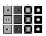
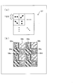
- FIG. 4D is an image showing a phase distribution when polarized laser light in the direction (P1) is transmitted through the subject, and FIG.
- 4D is a phase distribution when polarized laser light in the vertical direction (P2) is transmitted through the subject. It is an image. 3 is an image showing Stokes parameters S0 to S3 of object light. It is an image which shows the result of the simulation performed based on one embodiment about the reproduction picture of a subject. It is an image which shows the Stokes parameter calculated
- (A) is a schematic plan view showing a part of the first spatial light modulator
- (b) is a schematic plan view showing a part of the second spatial light modulator
- (c) shows the first spatial light modulator.
- (A) is a schematic diagram which shows a part of phase shift array device
- (b) is a schematic diagram which shows a part of wavelength selection filter
- (c) is a part of polarizer array device It is a schematic diagram shown.
- FIG. 4D is an image showing a phase distribution when polarized laser light in the direction (P1) is transmitted through the subject
- FIG. 4D is a phase distribution when polarized laser light in the vertical direction (P2) is transmitted through the subject.
- It is an image. 3 is an image showing Stokes parameters S0 to S3 of object light having wavelengths ⁇ 1 to ⁇ 3.
- FIG. 6 is an image showing Stokes parameters S0 to S3 of object light of wavelengths ⁇ 1 to ⁇ 3 obtained from a reproduced image and a phase distribution obtained by simulation. It is a schematic diagram which shows the structure of the polarization imaging apparatus of Embodiment 5 of this invention. It is a schematic diagram which shows a part of optical path length shift array device. It is a schematic diagram which shows the basic composition of the polarization imaging apparatus of Embodiment 6 of this invention. It is a figure for demonstrating the principle of operation of the said polarization imaging apparatus.
- FIG. 20 is a schematic diagram showing a configuration of another polarization imaging apparatus of the sixth embodiment.
- FIG. 20 is a schematic diagram showing a configuration of still another polarization imaging apparatus of the sixth embodiment.
- FIG. 20 is a schematic diagram showing a configuration of still another polarization imaging apparatus of the sixth embodiment.
- (A) (b) is a schematic diagram which shows the structure of the further another polarization imaging apparatus of Embodiment 6.
- (A) (b) is a schematic diagram which shows the structure of the further another polarization imaging apparatus of Embodiment 6.
- FIG. It is a figure for demonstrating the method of acquiring several wavelength information with one type of image sensor.
- (A) is a schematic diagram which shows the structure of the further another polarization imaging apparatus of Embodiment 6,
- (b) demonstrates the method of acquiring three-dimensional, polarized light, and several wavelength information with one type of image sensor.
- FIG. It is a perspective view which shows the structure of the image pick-up element for acquiring three-dimensional, polarized light, and several wavelength information with one kind of image sensor.
- FIG. 1 It is a figure which shows the flow until obtaining the three-dimensional image of the to-be-photographed object in a several polarization and several wavelength from the recorded hologram. It is a flowchart which shows the flow from the recorded hologram to the three-dimensional structure of an object, polarization distribution, and spectral image reproduction.
- (A) is a figure which shows the structure of the wavelength selection filter array provided with two types of filters
- (b) is a figure for demonstrating operation
- (A) is a schematic diagram which shows the structure of the further another polarization imaging apparatus of Embodiment 6
- (b) is a perspective view which shows the structure of the image pick-up element in the said polarization imaging apparatus.
- FIG. 10 is a diagram illustrating a configuration of a stacked image sensor according to a sixth embodiment. It is a perspective view which shows the structure of the image pick-up element using the said multilayer image sensor.
- FIG. 20 is a diagram for explaining a configuration of a hologram that is imaged by an imaging unit provided in the polarization imaging apparatus of the seventh embodiment. It is a schematic diagram which shows the structure of the said polarization imaging apparatus.
- FIG. 38 is a diagram illustrating a configuration of a hologram that is imaged by an imaging unit provided in another polarization imaging apparatus of the seventh embodiment. It is a schematic diagram which shows the structure of the said other polarization imaging apparatus.
- FIG. 25 is a diagram for explaining a configuration of a hologram that is imaged by an imaging unit provided in still another polarization imaging apparatus of the seventh embodiment. It is a schematic diagram which shows the structure of the said further another polarization imaging apparatus.
- the number of light sources is 1
- the number of polarization components having different reference light directions is 2
- the number of mutually different phases is 2 for polarization components in the first and second directions.
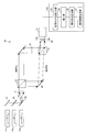
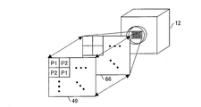
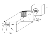
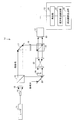
- FIG. 1 is a schematic diagram illustrating a configuration of the polarization imaging apparatus 1 according to the first embodiment.
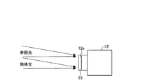
- the polarization imaging apparatus 1 includes an imaging apparatus having an optical system including a laser light source (light source) 11 and an imaging element (imaging unit) 12 having an imaging surface 12a made of a CCD. Furthermore, the polarization imaging apparatus 1 includes a calculator 13 connected to the output of the image sensor 12.
- the imaging device 12 includes a polarizer array device 23 disposed on the front surface of the imaging surface 12a.
- the laser light source 11 generates coherent light, that is, laser light.
- one direction perpendicular to the propagation direction of the laser light is defined as the first direction
- the propagation direction of the laser light and the direction perpendicular to the first direction are defined as the second direction.
- This laser light is linearly polarized light having a polarization component in the first direction and a polarization component in the second direction, that is, a polarization component in two directions.
- the first direction matches the horizontal direction
- the second direction matches the vertical direction.
- the polarization direction of the laser light is linearly polarized light that is inclined 45 ° from the first direction and that goes upward as viewed from the light traveling direction.
- the laser beam may be circularly polarized using a quarter wavelength plate.
- the polarization of the laser beam may be adjusted by arranging another polarizer or a wave plate.
- the laser light emitted (supplied) from the laser light source 11 passes through the beam expander 14 and the collimator lens 15 and becomes parallel light. Then, the laser light is split into reference light and object light by the beam splitter 16.
- the reference light and the object light are linearly polarized light having a polarization component in the first direction and a polarization component in the second direction, respectively.
- the object light that is one of the divided lights is reflected by the mirror 17 and applied to the subject 18.
- the object light incident on the subject 18 is diffracted or scattered by the subject 18 and is emitted from the subject 18. Thereafter, the object light is reflected by the beam combining element 19, passes through the polarizer array device 23, and enters the imaging surface 12 a of the imaging element 12.
- the beam combining element 19 is formed of a half mirror. The object light is incident substantially perpendicular to the imaging surface 12a.
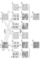
- FIG. 2A is a schematic plan view showing a part of the phase shift array device 21.
- the phase shift array device 21 has a plurality of regions in which the phases of the passed laser beams are different from each other.
- the phase shift array device 21 includes two types of phase shift regions 21a and 21b. With respect to the reference light that has passed through the phase shift region 21a, the phase of the reference light that has passed through the phase shift region 21b is shifted by ( ⁇ / 2) regardless of the polarization direction of the phase on the plane perpendicular to the traveling direction ( The phase is delayed by ⁇ / 2).
- the reference light that has passed through the phase shift region 21a is referred to as reference light having a phase shift amount of 0, and the reference light that has passed through the phase shift region 21b is referred to as reference light having a phase shift amount of ( ⁇ / 2).
- the phase shift array device 21 has a configuration in which linear phase shift regions 21a and linear phase shift regions 21b are alternately arranged. That is, the phase shift array device 21 can generate two reference lights having different phases.
- the phase shift array device 21 can be formed by, for example, glass and changing the thickness for each phase shift region.
- the plurality of regions that vary the phase of the phase shift array device 21 may be configured using wave plates, may be configured by changing the thickness for each phase shift region, It may be configured by providing a liquid crystal element and changing the direction of liquid crystal molecules, may be configured using other birefringent materials, or may be configured using an element having structural birefringence. Alternatively, a spatial light modulator may be used.
- the reference light that has passed through the phase shift array device 21 passes through the imaging optical unit 22, passes through the beam combining element 19, passes through the polarizer array device (polarizer array unit) 23, and the optical axis of the reference light is The light enters the imaging surface 12a so as to be substantially perpendicular to the imaging surface 12a of the imaging element 12.
- the reference light that has passed through the phase shift array device 21 is diffracted and imaged on the imaging surface 12 a by the imaging optical unit 22.
- the imaging optical unit 22 is composed of two lenses. However, the present invention is not limited to this, and the number of lenses may be one or more.
- the reference light that has passed through one phase shift region 21a or one phase shift region 21b of the phase shift array device 21 is imaged on pixels in any one row of the imaging surface 12a. That is, the reference light that has passed through one cell of the phase shift region 21a and the phase shift region 21b represented by being divided in a lattice shape in FIG. 2A is imaged on any one pixel of the imaging surface 12a.
- the In FIG. 2A, the region 21a and the region 21b of the phase shift array device 21 are drawn in a lattice shape, but the phase shift array device 21 may actually have a striped structure. .
- the imaging optical system of the polarization imaging apparatus 1 is composed of an inline type optical system, the optical axis of the reference light incident on the imaging surface 12a is perpendicular to the imaging surface 12a, and the subject 18 is optical on the imaging surface 12a. It is located in the front (optically normal direction of the imaging surface 12a).
- FIG. 2B is a schematic plan view showing a part of the polarizer array device 23 as viewed from the imaging surface 12a side.
- the polarizer array device 23 includes a polarizer (polarizer region) 23a that extracts only a polarized component in a certain direction (here, horizontal direction) of light that has passed therethrough, and only a polarized component in a direction orthogonal thereto (here, the vertical direction). Are arranged in a checkered pattern.
- the incident reference light and object light have a horizontal polarization component and a vertical polarization component.
- the first direction matches the horizontal direction
- the second direction matches the vertical direction. That is, the polarizers 23a and 23b pass only the polarization components corresponding to the polarization directions of the reference light and the object light.
- the object light and the reference light that have passed through the polarizer array device 23 are incident on the imaging surface 12a on the back surface.
- the intensity of light corresponding to the interference between the object light and the reference light is detected by the pixels on the imaging surface 12a, and the image sensor 12 captures an interference pattern (interference image) that the object light and the reference light make on the imaging surface 12a.
- each polarizer 23a * 23b respond
- the reference light that has passed through one cell divided by the grating shown in FIG. 2A of the phase shift array device 21 is imaged by the imaging optical unit 22, and one polarization of the polarizer array device 23.
- the imaging surface 12a has two types of interference in which the horizontal polarization components of the two reference lights having different phases interfere with the horizontal polarization components of the object light, and two reference lights having different phases.
- a pixel in which the reference light with horizontal polarization and phase shift amount 0 interferes with the object light with horizontal polarization, and the horizontal polarization and phase shift amount is ( ⁇ / 2).
- the reference light and the horizontally polarized object light interfere with each other, the vertically polarized pixel light with zero phase shift and the vertically polarized object light interfere with each other, and the vertically polarized light and the phase shift amount.
- the image pickup device 12 has two types of interference patterns with two directions of polarization in one image pickup and different phases in each direction, that is, four types of interference patterns formed on the image pickup surface 12a. Can be obtained.
- the calculator 13 includes a reproduction unit 24, a polarization state calculation unit 25, and a polarization image generation unit 35.
- the calculator 13 acquires image data indicating the interference pattern imaged by the image sensor 12 from the image sensor 12 and inputs the image data to the reproducing unit 24.
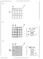
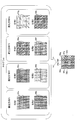
- FIG. 3 is a diagram for explaining an image reproduction algorithm in the reproduction unit 24.
- FIG. 3 shows only a part of the interference pattern (interference image) 26.
- the interference pattern 26 formed on the imaging surface 12a includes a pixel 27a in which the horizontal polarization component of the object light interferes with the horizontal polarization component of the reference light whose phase shift amount is 0, and the horizontal polarization component of the object light.
- the pixel 27b in which the horizontal polarization component of the reference light having the phase shift amount of ( ⁇ / 2) interferes, the vertical polarization component of the object light, and the vertical polarization component of the reference light having the phase shift amount of 0
- the pixel 27c in which the vertical polarization component of the object light interferes with the vertical polarization component of the reference light having a phase shift amount of ( ⁇ / 2).
- the reproduction unit 24 extracts these four types of pixels 27a, 27b, 27c, and 27d, respectively, so that the horizontal polarization component of the object light and the horizontal polarization component of the reference light having a phase shift amount of 0 are obtained.
- Interference pattern 28c with the vertical polarization component of the reference light of 0 and the interference pattern with the vertical polarization component of the object light and the vertical polarization component of the reference light with the phase shift amount ( ⁇ / 2) 28d is obtained.
- the reproducing unit 24 Based on the four interference patterns 28a to 28d obtained by dividing the pixels of the interference pattern 26, the reproducing unit 24 obtains a complex amplitude distribution of the horizontal polarization component and the vertical polarization component of the object light.
- the reproducing unit 24 includes an interference pattern 28a having horizontal polarization and a reference light phase shift amount of 0, an interference pattern 28b having horizontal polarization and a reference light phase shift amount of ( ⁇ / 2), and vertical polarization.
- the interference pattern 28c in which the phase shift amount of the reference light is 0 and the pixel in which the interference pattern 28d having the vertical polarization and the phase shift amount of the reference light ( ⁇ / 2) is missing both are the interference patterns 28a and 28b).
- the reproducing unit 24 acquires the intensity distribution 30 of the reference light from the image sensor 12. Since the reference light passes through the polarizer array device 23, the intensity distribution 30 of the reference light indicates the intensity of the polarization component in the horizontal direction of the reference light and the intensity of the polarization component in the vertical direction of the reference light. Both of the pixel 31b shown are included.
- the reproduction unit 24 extracts these two types of pixels 31a and 31b, respectively, thereby obtaining a horizontal polarization component intensity distribution 32a of the reference light and a vertical polarization component intensity distribution 32b of the reference light.
- the recording of the intensity distribution of the reference light is omitted, and the reproduction unit 24 performs the signal processing to obtain the complex amplitude distribution of the object light.
- An intensity distribution may be generated and used.
- an appropriate intensity distribution of the reference light can be estimated.
- the reproducing unit 24 removes pixels in which the intensity distribution 32a of the horizontal polarization component of the reference light and the intensity distribution 32b of the vertical polarization component of the reference light are missing (both white in the intensity distributions 32a and 32b).
- an intensity distribution 33a of the interpolated reference light in the horizontal direction and an intensity distribution 33b of the interpolated reference light in the vertical direction are obtained.
- the reproducing unit 24 Based on the interference patterns 29a and 29b having different interpolated phase shift amounts and the interpolated reference light intensity distribution 33a, the reproducing unit 24 performs a two-stage phase shift method (Non-Patent Document 3).
- the complex amplitude distribution 34a on the imaging surface 12a of the polarization component in the horizontal direction of the object light can be obtained using the reference).
- the reproducing unit 24 uses the interference patterns 29c and 29d having different interpolated phase shift amounts and the interpolated reference light intensity distribution 33b on the vertical polarization component, and the vertical polarization component of the object light.
- the complex amplitude distribution 34b on the imaging surface 12a can be obtained.
- the reproducing unit 24 can obtain a focused image (reproduced image showing an amplitude distribution) at an arbitrary depth position for each polarization component by performing diffraction integration based on the obtained complex amplitude distribution. Further, it is possible to obtain a phase distribution including information on the three-dimensional shape of the subject with respect to the focused image.
- the reproducing unit 24 outputs, to the polarization state calculating unit 25, the reproduced image and the phase distribution of the horizontal polarization component and the vertical polarization component obtained by calculation at the depth position of the subject.
- the polarization state calculation unit 25 represents a detailed polarization state at each position (each pixel) of the reproduction image based on the reproduction image and phase distribution of the polarization component in the horizontal direction and the reproduction image and phase distribution of the polarization component in the vertical direction. Find the Stokes parameters. First, the polarization state calculation unit 25 obtains the difference between the phase distribution of the polarization component in the horizontal direction and the phase distribution of the polarization component in the vertical direction. Next, the polarization state calculation unit 25 calculates Stokes parameters S0, S1, S2, and S3 at each position (each pixel) of the reproduced image based on the calculated phase difference distribution and the amplitude distribution of each polarization component.
- the Stokes parameter can be expressed by the following equation.
- a x is the amplitude distribution in the subject's horizontal polarization
- a y is the amplitude distribution in the subject's vertical polarization
- ⁇ x is the phase distribution in the subject's horizontal polarization
- ⁇ y is the phase distribution in the subject's vertical polarization.
- the polarization state calculation unit 25 may obtain a detailed polarization state by obtaining a Jones vector or a Mueller matrix instead of the Stokes parameter. Alternatively, the polarization state may be expressed by obtaining a parameter indicating another polarization state. The polarization state calculation unit 25 can obtain a detailed polarization state of the subject image from the complex amplitude distribution of the object light with respect to the horizontal and vertical polarization components.
- the polarization image generation unit 35 obtains the amplitude distribution in each polarization direction (for example, 0 ° direction (horizontal direction), 45 ° direction, 90 ° direction (vertical direction), 135 ° direction) of the subject from the Stokes parameters, and the polarization direction.
- the amplitude distribution is colored every time, and an image of the subject representing the polarization distribution is generated.
- the first embodiment in this way, four types of interference patterns having different reference light phases and polarization directions are obtained at a time by one imaging, and based on this, the detailed polarization state of the reproduced image is expressed.
- Polarization imaging is realized by obtaining the Stokes parameters.
- four types of interference patterns having different reference light phases and polarization directions are simultaneously formed on the same plane (imaging surface 12a), and pixels on the imaging surface are divided to simultaneously acquire the interference patterns. Therefore, information necessary for imaging the three-dimensional structure and polarization distribution of the subject can be acquired by one imaging. Therefore, it is possible to image a three-dimensional structure and polarization distribution of a subject with dynamic changes at a certain moment.
- the number of polarization adjusting elements can be reduced compared to the configuration described in Non-Patent Document 1 using off-axis digital holography, and the optical system can be simplified.
- the polarization imaging apparatus 1 can be made small.
- the inventor of the present application has at least two types of pixels for obtaining a polarization distribution (pixels having different polarization directions) and at least two types for obtaining three-dimensional information (for obtaining an object image using the phase shift method).
- the present invention invented a method (invention) of alternately arranging four types of pixels of a combination of these pixels (pixels having different reference light phases) on one imaging surface.
- the number of division multiplexing is at least four (the apparent number of pixels is 1 ⁇ 4 or less).
- the present invention has a wide field of view and high resolution as compared with the configuration of Non-Patent Document 1, and has an outstanding advantage over the prior art. It turns out that.
- a reproduced image and a polarization distribution with no deterioration can be obtained even though the apparent number of pixels is 1/4.
- the polarization direction of the laser light to be used does not have to be equal to the first direction and the second direction, and only needs to include polarization components in both the first direction and the second direction.
- the laser light may be circularly polarized light or elliptically polarized light.
- the first direction and the second direction are not limited to the horizontal direction and the vertical direction.
- the imaging optical system may be configured so that the passing reference light forms an image on a plurality of pixels (for example, 2 ⁇ 2 pixels) of the image sensor.
- one cell (polarizers 23a and 23b) of the polarizer array device does not have to correspond to one pixel of the image sensor, and one cell of the polarizer array device has a plurality of pixels (for example, 2 ⁇ 2 pixels). ).
- the reference light that has passed through the phase shift array device is divided into two types of reference light, but may be three or more types.
- the direction of the optical axis of the polarizer of the polarizer array device may be three or more. That is, four or more types of interference patterns having different combinations of the polarization direction and the phase of the reference light may be captured at a time, and the reproduced image and the Stokes parameter may be obtained based on the acquired interference patterns.
- a transmissive optical system that observes object light that has been transmitted and diffracted through a subject is used.
- the present invention is a reflective optical system that observes object light that is reflected and scattered by a subject. It can also be realized using a system.
- an interference pattern in each polarization direction is imaged using a polarizer array device.
- the present invention is not limited to this, and the object light and reference light received by the image sensor are divided into a plurality of parts by a beam splitter.
- an image sensor that passes through a polarizer in a different direction and picks up an image on each image pickup surface and picks up an interference pattern in each polarization direction may be used.
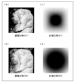
- FIG. 4A An optical system for imaging a subject is the polarization imaging apparatus 1 shown in FIG. 4A is an image showing the amplitude distribution of the polarization component in the horizontal direction (P1) that represents the lightness and darkness of the subject
- FIG. 4B is a vertical image that represents the lightness and darkness of the subject. It is an image which shows amplitude distribution of the polarization component of a direction (P2).
- the subject is an object having a square cross section in a plane perpendicular to the direction in which object light is transmitted, and a cat image is formed on the subject.
- 4C corresponds to FIG. 4A, and is an image showing the phase distribution when the laser beam polarized in the horizontal direction (P1) is transmitted through the subject.
- FIG. 4B is an image showing the phase distribution when the laser beam polarized in the vertical direction (P2) is transmitted through the subject, corresponding to FIG. 4B.
- the phase delay is expressed in light and dark, and the darkest part is delayed by 1.5 ⁇ in the phase of the laser beam (object light) compared to the brightest part.
- FIG. 5A is an image showing the Stokes parameter S0 of the object light diffracted by the subject
- FIG. 5B is an image showing the Stokes parameter S1 of the object light diffracted by the subject
- FIG. 5C is an image showing the Stokes parameter S2 of the object light diffracted by the subject
- FIG. 5D is an image showing the Stokes parameter S3 of the object light diffracted by the subject.
- the brighter the portion the larger the Stokes parameter.
- the wavelength ⁇ of the laser beam used is 532 nm
- the size of the cross section of the subject is 3.69 mm ⁇ 3.69 mm
- the distance between the subject and the imaging surface of the image sensor is 50 mm
- the size of each pixel of the image sensor is 1.8 ⁇ m ⁇ 1.8 ⁇ m
- the pixels of the image sensor The number was assumed to be 2048 ⁇ 2048 pixels and the pixel pitch was 1.8 ⁇ m.
- a computer obtains an interference pattern formed on the imaging surface by the object light of the subject and the reference light, calculates a reconstructed image, and performs a simulation for obtaining a Stokes parameter of the reconstructed image based thereon.
- the interference pattern is also obtained by computer simulation.
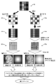
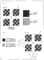
- 6 (a) to 6 (d) are images showing the results of the simulation performed based on the present embodiment with respect to the reproduced image of the subject.
- 6A is an image showing the amplitude distribution of the P1 polarization component in the reproduced image
- FIG. 6B is an image showing the amplitude distribution of the P2 polarization component in the reproduced image.
- (C) of FIG. 6 is an image showing the phase distribution of the polarization component of P1 in the reproduced image corresponding to (a) of FIG. 6, and (d) of FIG. 6 corresponds to (b) of FIG.
- the image shows the phase distribution of the P2 polarization component in the reproduced image. According to the present embodiment, it can be seen that an accurate and clear reproduced image and an accurate phase distribution can be obtained even when the captured interference pattern is divided into four and four types of interference patterns having different phases and polarization directions are obtained.
- FIG. 7 are images showing Stokes parameters obtained from a reproduced image and a phase distribution obtained by simulation.
- 7A is an image showing the Stokes parameter S0 in the reproduced image
- FIG. 7B is an image showing the Stokes parameter S1 in the reproduced image
- FIG. 7C is a reproduced image
- FIG. 7D is an image showing the Stokes parameter S3 in the reproduced image. Comparing FIG. 7 (a) to FIG. 7 (d) with FIG. 5 (a) to FIG. 5 (d), the original Stokes parameters are accurately reproduced by the polarization imaging simulation of this embodiment. You can see that it was made. That is, according to the present embodiment, it is possible to accurately acquire the three-dimensional structure and detailed polarization state of a subject with dynamic changes and perform polarization imaging.
- the imaging surface is divided into four and a hologram (interference pattern) is multiplexed and recorded.
- a hologram interference pattern
- the imageable range that is, the size of the subject that can be measured is It becomes larger than that of Non-Patent Document 1 using an off-axis type optical system.
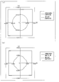
- FIG. 8 is a figure which shows the imaging range in the polarization imaging apparatus of this Embodiment, and the imaging range in an off-axis type polarization imaging apparatus.
- the reference light is assumed to be parallel light.
- the polarization imaging apparatus of the present embodiment can capture a larger subject (a larger range) than the off-axis polarization imaging apparatus.
- the pixel pitch of the image sensor is 1.8 ⁇ m
- the wavelength of the laser beam is 532 nm
- the area of the imaging surface is 1.84 mm ⁇ 1.84 mm.
- the distance between the subject and the imaging surface was 300 mm.
- the imageable range is a range (field of view) in which a clear reproduced image is obtained. If it is out of the imaging range, problems such as superposition of 0th-order diffracted light or conjugate image, aliasing, and accompanying ghost image generation occur, and image quality deteriorates.
- the range in which a clear reproduced image is obtained is a limit range where the above-described problem does not occur.
- FIG. 8B is a diagram illustrating an imageable range in the polarization imaging apparatus of the present embodiment and an imageable range in the off-axis type polarization imaging apparatus.
- the pixel pitch of the imaging device is 5 ⁇ m
- the wavelength of the laser beam is 532 nm
- the area of the imaging surface is 2.56 mm ⁇ 2.56 mm
- the distance between the imaging surface was 300 mm.
- the polarization imaging apparatus of the present embodiment can image a subject (large range) that is four times larger than the off-axis polarization imaging apparatus.
- the second embodiment will be described in detail with reference to FIG. 9 to FIG.
- the number of light sources is 1
- the number of polarization components having different reference light directions is 2
- the number of mutually different phases is 2 for polarization components in the first and second directions.
- members / configurations having the same functions as the members / configurations described in the first embodiment are denoted by the same reference numerals, and only portions different from the first embodiment will be described below.
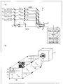
- FIG. 9 is a schematic diagram showing a configuration of the polarization imaging apparatus 2 of the second embodiment.
- the laser light source 11 of the polarization imaging apparatus 2 emits linearly polarized laser light having a polarization component in the second direction (vertical direction).
- the polarization imaging apparatus 2 includes a half-wave plate 36 that adjusts the deflection direction, a first spatial light modulator 37 that adjusts the deflection direction, and a second spatial light modulator 38 that performs phase shift.
- the polarization imaging apparatus 2 does not include the phase shift array device and the polarizer array device of the first embodiment.
- the object light polarized in the vertical direction divided by the beam splitter 16 is rotated by 45 ° by the half-wave plate 36 to be converted into polarized light in which the vertical polarization component and the horizontal polarization component are equal. Is done. Then, the subject 18 is irradiated with object light (an obliquely polarized object light) including a vertical polarization component and a horizontal polarization component. The object light transmitted and diffracted through the subject 18 is reflected by the beam combining element 19 and enters the image pickup surface 12 a of the image pickup element 12. The object light may be converted into circularly polarized light or elliptically polarized light using a quarter wavelength plate or the like.
- FIG. 10A is a schematic plan view showing a part of the first spatial light modulator 37.
- the first spatial light modulator (polarization direction changing array unit) 37 includes a first direction region 37a that rotates the polarization direction of the laser beam that has passed through 90 °, and a second direction that allows the laser beam to pass without changing the polarization direction.
- a plurality of regions 37b are provided.
- the vertically polarized reference light that has entered the first direction region 37a is rotated by 90 ° in the polarization direction, and is emitted from the first direction region 37a as horizontally polarized reference light.
- the first spatial light modulator 37 has a configuration in which linear first direction regions 37a and linear second direction regions 37b are alternately arranged in the vertical direction.
- the action of the polarization direction of the incident reference light, the first direction region, and the second direction region is not limited to the above example, and the first direction region of the first spatial light modulator converts the incident reference light into the first direction. It is only necessary to convert the reference light polarized in the direction, and the second direction region of the first spatial light modulator is configured to convert the incident reference light into the reference light polarized in the second direction.
- FIG. 10B is a schematic plan view showing a part of the second spatial light modulator 38.
- the second spatial light modulator (phase shift array unit) 38 has a plurality of regions that make the phases of the laser beams that have passed through differ from each other.
- the second spatial light modulator 38 includes two types of phase shift regions 38a and 38b. With respect to the reference light that has passed through the phase shift region 38a, the phase of the reference light that has passed through the phase shift region 38b is shifted by ( ⁇ / 2) regardless of the polarization direction of the phase on the plane perpendicular to the traveling direction ( The phase is delayed by ⁇ / 2).
- the second spatial light modulator 38 has a configuration in which linear phase shift regions 38a and linear phase shift regions 38b are alternately arranged in the horizontal direction.
- FIG. 10C is a schematic diagram illustrating a state of a part of the reference light immediately after passing through the second spatial light modulator 38, corresponding to FIG.
- the reference light passing through the region 39a is horizontally polarized light, and the phase shift amount is zero.
- the reference light passing through the region 39b is horizontally polarized light, and the phase shift amount is ( ⁇ / 2).
- the reference light passing through the region 39c is vertically polarized light, and the phase shift amount is zero.
- the reference light passing through the region 39d is vertically polarized light, and the phase shift amount is ( ⁇ / 2).
- An interference pattern in which four types of reference light and obliquely polarized object light interfere with each other is formed on the imaging surface 12a. That is, each pixel on the imaging surface 12a measures the light intensity at which any of the four types of reference light interferes with the obliquely polarized object light.
- polarization imaging can be performed by obtaining a complex amplitude distribution of object light, generating a reproduction image and a phase distribution, and obtaining a Stokes parameter.
- polarization imaging camera provided with a polarizer array device
- polarization imaging can be realized using a simple image sensor. It is also possible to compensate for aberrations caused by the imaging optical unit 22 by any one of the spatial light modulators 37 and 38. Further, in the present embodiment, the two spatial light modulators 37 and 38 are arranged side by side in the reference light path and act only on the reference light, so that the imaging optical unit 22 can be easily adjusted.
- the problem is that the phase of light is distorted when the polarizer array is distorted and bonded, and the polarizer array and the image sensor are bonded. There is a problem that misalignment occurs. Correction cannot be made once the polarizer array is bonded to the image sensor.
- the second embodiment has a feature that it is not necessary to attach the polarizer array to the image sensor, and the optical system can be easily adjusted.
- two lights with the same polarization direction cause interference, but two lights with different polarization directions do not cause interference.
- the horizontal polarization component of the object light and the reference light interfere with each other on the pixel where the phase shift amount is 0 and the horizontally polarized reference light and the obliquely polarized object light are incident.
- the vertically polarized component does not cause interference.
- the vertically polarized component of the object light interferes with the reference light.
- the horizontal polarization component of the object light does not cause interference.
- the imaging device 12 also measures a polarization component that does not participate in the interference of the object light, but the influence of the polarization component that does not participate in the interference of the object light is removed together with the influence of the zero-order diffracted light in the calculation process by the phase shift method can do.
- a method for removing the influence of the polarization component of the object light not involved in interference will be described.
- the intensity A o 2 (x, y) of the object light on the imaging surface 12a can be expressed by the following equation.
- a oP1 2 (x, y) is the intensity of the polarization component in the horizontal direction (P1) of the object light
- a oP2 2 (x, y) is the polarization component in the vertical direction (P2) of the object light. Of strength.
- I A (x, y) is the intensity of light detected by a pixel on which a reference light having a phase shift amount of 0 and horizontally polarized light is incident, and the reference light is a horizontally polarized light having a phase shift amount of ( ⁇ / 2).
- I B (x, y) is the intensity of the light detected by the pixel on which the light is incident
- I C (x, y) is the intensity of the light detected by the pixel on which the reference light that is vertically polarized with zero phase shift is incident.
- I D (x, y) be the intensity of the light detected by the pixel to which the reference light that is vertically polarized and has a phase shift amount of ( ⁇ / 2). Since the reference light incident on each pixel does not interfere with the object light in the orthogonal polarization direction, the intensity of light detected by each pixel can be expressed by the following four expressions.
- a r (x, y) represents the amplitude of the reference beam in the imaging plane 12a
- ⁇ oP1 (x, y ) is the object light on the imaging plane 12a respectively P1 And the phase of the polarization component of P2.
- t (x, y) is the intensity of the 0th-order diffracted light component and the non-interference component of the object light (polarized component orthogonal to the reference light). It is the sum of the intensity.
- I A (x, y), I B (x, y), I C (x, y), I D (x, y), and A r (x, y) are measurable quantities
- the values of t (x, y) can be obtained from the equations (11) to (17), and each polarization of the object light is obtained from the obtained t (x, y) and the equations (6) to (9).
- the third embodiment will be described in detail with reference to FIG.
- the number of light sources is 1
- the number of polarization components having different reference light directions is 2
- the number of mutually different phases is 2 for polarization components in the first and second directions.
- members / configurations having the same functions as the members / configurations described in the first embodiment are denoted by the same reference numerals, and only portions different from the first embodiment will be described below.
- an application to a polarization microscope suitable for observation of a biological sample such as a cell will be described.
- FIG. 11 is a schematic diagram showing a configuration of the polarization imaging apparatus 3 of the present embodiment.
- the polarization direction of the laser light emitted from the laser light source 11 of the polarization imaging apparatus 3 is a polarization direction that is inclined 45 ° from the first direction and that rises to the right when viewed from the light traveling direction. In addition, you may make a laser beam into circularly polarized light etc. using a quarter wavelength plate.
- the polarization imaging apparatus 3 includes a spatial light modulator 40, an imaging optical unit (wavefront conversion unit) 41, a spatial filtering element 42, and a microscope objective lens 43.
- the polarization imaging apparatus 3 does not include the phase shift array device of the first embodiment.
- the object light transmitted and diffracted through the subject 18 is magnified by the microscope objective lens (magnifying optical unit) 43. That is, when the subject 18 is observed through the microscope objective lens 43, an enlarged image of the subject 18 can be observed.
- the object light that has passed through the microscope objective lens 43 is reflected by the beam combining element 19 and enters the imaging surface 12 a of the imaging element 12.
- the reference light divided by the beam splitter 16 is reflected by the mirror 20 and passes through the spatial light modulator (phase shift array unit) 40.
- the spatial light modulator 40 performs a phase shift action on the passing reference light in the same manner as the spatial light modulator 38 shown in FIG. That is, the spatial light modulator 40 has two types of regions, and the phase of the reference light that has passed through the second region differs from that of the reference light that has passed through the first region by ( ⁇ / 2). .
- the reference light that has passed through the spatial light modulator 40 passes through the imaging optical unit 41 and the spatial filtering element 42, passes through the beam combining element 19, passes through the polarizer array device 23, and enters the imaging surface 12a.
- the two types of reference light that have passed through the spatial light modulator 40 are imaged on each pixel of the imaging surface 12a of the imaging element 12 by the imaging optical unit 41 and the spatial filtering element 42, respectively.
- the imaging optical unit 41 emits the reference light as a spherical wave (or an aspheric wave).
- the spatial filtering element 42 has a pinhole, and removes the component of the reference light that diffracts through each cell of the spatial light modulator 40.
- the polarizer array device 23 selectively selects only the polarization component in the first direction (horizontal direction) or the polarization component in the second direction (vertical direction) for the object beam and the reference beam. To pass through. Therefore, on the imaging surface 12a, pixels in which horizontally polarized reference light having a phase shift amount of 0 and horizontally polarized object light interfere with each other, and horizontally polarized reference light having a phase shift amount of ( ⁇ / 2).
- Object light diffracted from one point of the subject 18 reaches the imaging surface 12a as a spherical wave (or an aspheric wave).
- the reference light when the reference light is incident as a plane wave from a direction perpendicular to the imaging surface 12a, the reference light that is a plane wave and the object light that is a spherical wave (or an aspheric wave) are partially directed to the imaging surface 12a.
- the incident angle will be different. Different incident angles on the imaging surface 12a means that the spatial frequency of the interference pattern formed on the imaging surface 12a is increased (interference fringe spacing is reduced), and the three-dimensional structure of the details of the subject is recorded. Therefore, a high-resolution image sensor is required.
- the reference light is converted into a spherical wave (or an aspheric wave) in accordance with the object light and is incident on the imaging surface 12a. Therefore, the angle difference between the traveling directions of the reference light and the object light is reduced, The interval between the interference fringes can be increased. For this reason, it is possible to record an interference pattern including information on the three-dimensional structure of the details of the subject using a low-resolution image sensor. Therefore, according to the polarization imaging apparatus 3 of the third embodiment, the details of the image of the subject 18 enlarged using the microscope objective lens 42 can be observed more accurately by polarization imaging. Even if the reference light is incident on the imaging surface 12a as a plane wave, it can be used as a polarizing microscope.
- Non-Patent Document 1 The configuration using an off-axis optical system (Non-Patent Document 1) is essentially a configuration in which it is essential to make a difference between the incident angle of the object light and the incident angle of the reference light. The details cannot be observed with high accuracy.
- FIG. 12 is a schematic diagram showing a configuration of the polarization imaging apparatus 4 of the fourth embodiment.
- the number of light sources is 3, the number of polarization components having different reference light directions for each light source is 2, and the number of phases different from each other for the polarization components in the first and second directions is 2.
- the polarization imaging apparatus 4 includes three types of laser light sources 11a, 11b, and 11c that emit laser beams having different wavelengths, a mirror 44, beam combining elements 45 and 46, and a phase shift array device 47.
- the polarization imaging apparatus 4 includes a wavelength selection filter 48 and a polarizer array device 49 that are disposed in front of the imaging surface 12 a of the imaging element 12.
- the laser light source 11a emits laser light having a wavelength ⁇ 1
- the laser light source 11b emits laser light having a wavelength ⁇ 2
- the laser light source 11c emits laser light having a wavelength ⁇ 3.
- the laser light having the wavelength ⁇ 3 emitted from the laser light source 11c is reflected by the mirror 44, and the laser light having the wavelength ⁇ 2 emitted from the laser light source 11b is reflected by the beam coupling element 45, and is reflected from the laser light source 11a by the beam coupling element 46.
- the emitted laser light of wavelength ⁇ 1 and the optical axis are aligned.
- the polarization direction of the laser light emitted from each of the laser light sources 11a, 11b, and 11c is an upward polarization direction that is inclined 45 ° from the first direction and is viewed from the light traveling direction.
- the laser light of each wavelength is divided into object light and reference light of each wavelength by the beam splitter 16.
- FIG. 13A is a schematic diagram showing a part of the phase shift array device 47.
- the phase shift array device 47 has a plurality of regions that make the phases of the laser beams that have passed through differ from each other.
- the phase shift array device 47 is composed of six types of phase shift regions 47a to 47f.
- the reference light having the wavelength ⁇ 1 that has passed through the phase shift region 47a has a phase on a plane perpendicular to the traveling direction regardless of the polarization direction ( ⁇ / 2) is shifted.
- the reference light having the wavelength ⁇ 2 that has passed through the phase shift region 47d and the reference light having the wavelength ⁇ 2 that has passed through the phase shift region 47c has a phase on a plane perpendicular to the traveling direction regardless of the polarization direction ( - ⁇ / 2).
- the reference light having the wavelength ⁇ 3 that has passed through the phase shift region 47f has a phase on a plane perpendicular to the traveling direction regardless of the polarization direction ( ⁇ / 2) is shifted.
- the phase shift of the reference light having the wavelength ⁇ 2 or ⁇ 3 that has passed through the phase shift regions 47a and 47b is not a problem.
- reference light that has passed through the phase shift regions 47a, 47c, and 47e is reference light that has a phase shift amount of 0, and reference light that has passed through the phase shift regions 47b, 47d, and 47f has a phase shift amount of ( ⁇ / 2). It is described as a reference beam.
- phase shift array device 47 these six types of phase shift regions 47a to 47f are arranged as shown in FIG. 13A, and the structure of 4 ⁇ 4 cells shown in the figure is periodically arranged.
- the phase shift array device 47 can be formed by, for example, glass and changing the thickness for each phase shift region.
- the reference light that has passed through the phase shift array device 47 passes through the imaging optical unit 22, passes through the beam combining element 19, passes through the wavelength selection filter 48, passes through the polarizer array device 49, and passes through the light of the reference light.
- the light enters the imaging surface 12a so that the axis is substantially perpendicular to the imaging surface 12a.
- the reference light that has passed through the phase shift array device 47 is diffracted and imaged on the imaging surface 12 a by the imaging optical unit 22.
- the imaging optical unit 22 is composed of a plurality of lenses.
- the reference light that has passed through one phase shift region 47a of the phase shift array device 47 is imaged on any one pixel of the imaging surface 12a. That is, the reference light that has passed through one cell of the phase shift areas 47a to 47f partitioned in a lattice form is imaged on any one pixel of the imaging surface 12a.
- the object light of each wavelength diffracted and scattered by the subject 18 is reflected by the beam combining element 19, passes through the wavelength selection filter 48, passes through the polarizer array device 49, and enters the imaging surface 12 a of the imaging element 12. Incident.
- the wavelength selection filter 48 is a filter that selectively allows light to pass according to the wavelength.
- the first wavelength selection region 48a that passes light of wavelength ⁇ 1 and blocks light of wavelengths ⁇ 2 and ⁇ 3, and passes light of wavelength ⁇ 2.
- a plurality of second wavelength selection regions 48b that block light of wavelengths ⁇ 1 and ⁇ 3 and a plurality of third wavelength selection regions 48c that transmit light of wavelength ⁇ 3 and block light of wavelengths ⁇ 1 and ⁇ 2 are arranged.
- FIG. 13C is a schematic diagram showing a part of the polarizer array device 49 viewed from the imaging surface 12a side.
- the polarizer array device 49 includes a polarizer 49a that extracts only a polarized component in a certain direction (here, horizontal direction) of light that has passed therethrough, and a polarizer 49b that extracts only a polarized component in a direction orthogonal thereto (here, the vertical direction).
- the incident reference light and object light have a horizontal polarization component and a vertical polarization component.
- the first direction matches the horizontal direction
- the second direction matches the vertical direction. That is, the polarizers 49a and 49b pass only the polarization components corresponding to the polarization directions of the object light and the reference light.
- the object light and the reference light that have passed through the polarizer array device 49 are incident on the imaging surface 12a on the back surface.
- the intensity of light according to the interference between the object light and the reference light is detected by the pixels on the imaging surface 12a, and the image sensor 12 images an interference pattern formed on the imaging surface 12a by the object light and the reference light.
- the polarizer array device 49 and the wavelength selection filter 48 are pasted adjacent to the imaging surface 12a, the individual wavelength selection regions 48a to 48c separated by the grating and the individual separated by the grating.
- the polarizers 49a and 49b correspond to one pixel on the imaging surface 12a.
- phase shift regions 47a to 47f the reference light that has passed through one cell (phase shift regions 47a to 47f) delimited by the grating of the phase shift array device 47 is imaged by the imaging optical unit 22 and is selected by one wavelength selection filter 48. It passes through the regions 48a to 48c and one polarizer 49a, 49b of the polarizer array device 49.
- FIG. 14 is a diagram showing a part of the interference pattern 50 obtained by the polarization imaging apparatus 4.
- the interference pattern 50 formed on the imaging surface 12a is a pixel 51a in which the phase shift amount of the wavelength ⁇ 1 is 0 and the horizontal component of the object light and the reference light interferes, and the phase shift amount of the wavelength ⁇ 1 is ( ⁇ / 2).
- the pixel 51b in which the horizontal components of the light and the reference light interfere, the pixel 51c in which the phase shift amount of the wavelength ⁇ 1 is zero and the vertical component of the object light and the reference light interfere, and the phase shift amount of the wavelength ⁇ 1 is ( ⁇ / 2) ),
- the computer 13 acquires image data indicating the interference pattern 50 imaged by the image sensor 12 from the image sensor 12.
- the reproducing unit 24 of the computer 13 extracts these 12 types of pixels 51a to 51l, respectively, and thus, similar to the interference patterns 28a to 28d shown in FIG. 3 for each of the three types of wavelengths, an interference pattern corresponding to the type of pixel. Can be obtained.
- For the interference pattern of each wavelength by interpolating the missing pixels as in the first embodiment and using the two-stage phase shift method, six types of complex amplitude distributions for each wavelength and polarization component are obtained. A reproduced image and a phase distribution can be obtained.
- the polarization state calculation unit 25 can calculate the Stokes parameters of the reproduction image for each wavelength by using the obtained reproduction image and the phase distribution, and obtain a detailed polarization state.
- the polarization image generation unit 35 can generate an object image representing the polarization distribution of each wavelength by coloring the amplitude distribution for each polarization direction of each wavelength.
- spectroscopy is performed using the laser light sources 11a to 11c having a plurality of wavelengths, and polarization imaging at each wavelength is performed simultaneously (by one imaging). Can do.
- the wavelength selection filter 48 and the polarizer array device 49 may be reversed. Therefore, this embodiment can be configured using a commercially available color CCD camera with a wavelength selection filter attached, and spectral information can be acquired.
- the wavelength selection filter 48 having a Bayer arrangement is used.
- the present invention is not limited to this. Multiple pixels (red, green, and blue) light can be detected separately in one pixel by using the characteristics of a three-element image sensor that captures interference patterns of different wavelengths or a silicon sensor that absorbs light at different depths depending on the wavelength.
- An imaging device see Non-Patent Document 4 or the like can also be used.
- FIG. 15A is an image showing the amplitude distribution of the polarization component in the horizontal direction (P1) that represents the lightness and darkness of the subject
- FIG. 15B is a vertical image that represents the lightness and darkness of the subject. It is an image which shows amplitude distribution of the polarization component of a direction (P2).
- the subject is an object having a square cross section in a plane perpendicular to the direction in which object light is transmitted, and an image of the character “KIT” is formed on the subject.
- FIG. 15C corresponds to FIG. 15A, and is an image showing the phase distribution when the laser beam polarized in the horizontal direction (P1) is transmitted through the subject
- FIG. 15C corresponds to FIG. 15A, and is an image showing the phase distribution when the laser beam polarized in the horizontal direction (P1) is transmitted through the subject
- FIG. 16 is an image showing the Stokes parameters S0 to S3 of the object light having the wavelengths ⁇ 1 to ⁇ 3 diffracted by the subject.
- the brighter the part the larger the Stokes parameter.
- the vertical and horizontal sizes of the image shown in (a) is 3.69 mm ⁇ 3.69 mm, and the distance between the subject and the imaging surface of the imaging device (the distance along the optical axis of the object light) is 50 mm. It is assumed that the size of each pixel of the image sensor is 1.8 ⁇ m ⁇ 1.8 ⁇ m, the number of pixels of the image sensor is 2048 ⁇ 2048 pixels, and the pixel pitch is 1.8 ⁇ m.
- a computer obtains an interference pattern formed on the imaging surface by the object light of the subject and the reference light, calculates a reconstructed image, and performs a simulation for obtaining a Stokes parameter of the reconstructed image based thereon.
- the interference pattern is also obtained by computer simulation.
- FIG. 17 are images showing the results of simulations performed on the reproduced image of the subject based on the fourth embodiment.
- 17A is an image showing an amplitude distribution obtained by adding the amplitude distribution of the P1 polarization component in the reproduction image of each wavelength
- FIG. 17B is a polarization component of P2 in the reproduction image of each wavelength.
- 17 (c) is an image showing the phase distribution of the P1 polarization component in the reproduced image corresponding to FIG. 17 (a).
- 17D is an image corresponding to FIG. 17B and showing the phase distribution of the polarization component of P2 in the reproduced image. Since the wavelength distribution is not set for the phase distribution as a simulation condition, the phase distribution in FIGS.
- 17C and 17D shows the phase distribution at a certain wavelength. According to the fourth embodiment, it is understood that an accurate and clear reproduced image and an accurate phase distribution can be obtained even when the captured interference pattern is divided into 12 to obtain 12 types of interference patterns having different phases and polarization directions.
- FIG. 18 is an image showing the Stokes parameters S0 to S3 of the object light of the wavelengths ⁇ 1 to ⁇ 3 obtained from the reproduced image and the phase distribution obtained by the simulation. Comparing FIG. 18 and FIG. 16, it can be seen that the original Stokes parameters can be accurately reproduced by the polarization imaging simulation of the fourth embodiment. That is, according to the present embodiment, it is possible to accurately acquire a three-dimensional structure of a subject with dynamic changes and detailed polarization states related to a plurality of wavelengths, and perform spectroscopy and polarization imaging.
- the wavelengths of the laser light to be used there are three types of wavelengths of the laser light to be used.
- the wavelengths of the laser light to be used may be two types or more than three types. Further, not only visible light but also light having a wavelength such as infrared, ultraviolet, and X-ray may be used.
- FIG. 19 is a schematic diagram illustrating a configuration of the polarization imaging apparatus 5 according to the fifth embodiment.
- the number of light sources is 1, the number of polarization components having different reference light directions is 2, and the number of mutually different phases is 2 for polarization components in the first and second directions.
- the polarization direction of the laser light emitted from the laser light source 11 of the polarization imaging device 5 is a polarization direction that is inclined 45 ° from the first direction and that rises to the right when viewed from the light traveling direction.
- the polarization imaging apparatus 5 includes an optical path length shift array device (having an optical path length shift array unit and a phase shift adjustment function) 52 disposed in front of the imaging surface 12a of the imaging element 12.
- the optical path length shift array device 52 and the polarizer array device 23 are attached adjacent to the front surface of the imaging surface 12a.
- the polarization imaging apparatus 5 does not include the phase shift array device 21 and the imaging optical unit 22.
- the object light transmitted and diffracted through the subject 18 is reflected by the beam combining element 19 and enters the imaging surface 12 a of the imaging element 12.
- the reference light split by the beam splitter 16 is reflected by the mirror 20, passes through the beam combining element 19, and enters the imaging surface 12 a of the imaging element 12 at a substantially vertical incident angle.
- Both the object light and the reference light pass through the polarizer array device 23 and the optical path length shift array device 52, and enter the imaging surface 12a.
- the polarizer array device 23 is shown in FIG.
- FIG. 20 is a schematic diagram showing a part of the optical path length shift array device 52 as viewed from the imaging surface 12a side.
- the optical path length shift array device 52 has a plurality of regions in which the optical path lengths of the passed laser beams are different from each other.
- the optical path length shift regions 52a and 52b of the optical path length shift array device 52 are composed of quarter wavelength plates whose optical axes are orthogonal to each other.
- the high-speed axis of the optical path length shift region 52a coincides with the horizontal direction, and the low-speed axis coincides with the vertical direction.
- the high speed axis of the optical path length shift region 52b coincides with the vertical direction, and the low speed axis coincides with the horizontal direction.
- the phase of the horizontally polarized reference light and object light that has passed through the optical path length shift region 52b is only ( ⁇ / 2) with respect to the horizontally polarized reference light and object light that has passed through the optical path length shift region 52a. Shift. That is, an optical path difference of 1 ⁇ 4 wavelength is generated as the optical path length between the subject 18 and the imaging surface 12a.
- the phase of the vertically polarized reference light and object light that has passed through the optical path length shift region 52a is only ( ⁇ / 2) with respect to the vertically polarized reference light and object light that has passed through the optical path length shift region 52b. Shift.
- the image sensor 12 captures an interference pattern including four types of interference formed on the imaging surface 12a, and the reproducing unit 24 separates the four types of pixels and separates the four types of interference as in the first embodiment. Get a pattern. Thereafter, the reproducing unit 24 obtains the complex amplitude distribution of the horizontal polarization component and the complex amplitude distribution of the vertical polarization component using the optical path length shift method. Subsequent processing up to polarization imaging is the same as in the first embodiment. In the fifth embodiment, the polarizer array device 23 and the optical path length shift array device 52 are attached to the image pickup surface 12a and attached to the image pickup device 12. Therefore, if such an image pickup device camera is manufactured, Thereafter, the system formation of the polarization imaging apparatus becomes extremely simple.
- Embodiment 6 instead of using a phase shift device for the reference light, an embodiment of the present invention is described in which a plurality of holograms are obtained by changing the incident angle of the reference light to the image sensor.
- FIG. 21 is a schematic diagram showing a basic configuration of the polarization imaging apparatus 1a according to the sixth embodiment of the present invention.
- the same components as those described above are denoted by the same reference numerals, and detailed description thereof will not be repeated.
- a single reference light is incident on the polarizer array device 23 provided in the imaging device 12 of the polarization imaging apparatus 1a from a direction different from the object light.
- a spatially phase-shifted hologram is acquired on the imaging surface without using a device for performing the phase shift function, and simple image processing called the spatial carrier shift method is used. Extracts subject information and realizes instant 3D polarization imaging.
- FIG. 22 is a diagram for explaining the operating principle of the polarization imaging apparatus 1a.
- the number of light sources is 1, the number of polarization components having different reference light directions is 2, and the number of mutually different phases is 4 for the polarization components in the first and second directions.
- This principle of operation is to acquire a hologram whose phase is spatially shifted.
- the reference light is made incident at an inclination angle ⁇ with respect to the object light (meaning diffracted light or scattered light from the object) incident from a direction perpendicular to the imaging surface formed on the image sensor 12, and the image sensor 12.
- the phase of the reference light is shifted by the tilted amount in each pixel.
- each symbol is ⁇ : wavelength of reference light
- ⁇ The pixel interval of the image sensor 12.
- the inclination angle ⁇ is, (sin -1 ( ⁇ / 4 ⁇ ) ) is most preferably a strictly (sin -1 ( ⁇ / 4 ⁇ ) ) but need not, (sin -1 ( ⁇ / 4 ⁇ ) If the angle is based on (), the effect of the present invention is achieved.
- phase shift amount of the reference light on the imaging surface is continuously shifted by ( ⁇ / 2) at every adjacent pixel interval ⁇ .
- the phase shift amount of the reference light is easy to understand. Is schematically represented.
- the interference between the reference light and the object light forms a spatially phase-shifted hologram on the imaging surface as shown in FIG.
- the hologram thus obtained is hereinafter referred to as a spatial carrier phase shift hologram.
- a spatial carrier phase-shift hologram can be obtained by a single shot.
- FIG. 23 is a schematic diagram showing a configuration of the polarization imaging apparatus 1a.
- the number of light sources is 1, the number of polarization components having different reference light directions for each light source is 2, and the number of phases different from each other for the polarization components in the first and second directions is 4. is there.
- the same components as those described above are denoted by the same reference numerals, and detailed description thereof will not be repeated.
- the light emitted from the laser light source 11 has at least a polarization component in the same direction as the polarization component of the polarizer in the polarizer array device 23.
- the configuration of the polarizer array device 23 is the same as that described above with reference to FIG.
- the light emitted from the laser light source 11 is converted into expanded parallel light and then divided into two waves by the beam splitter 16.
- One light is irradiated to the subject 18, and the diffracted light from the subject 18 enters the image sensor 12 with the polarizer array device 23 as object light.
- the other light is incident on the image sensor 12 with the polarizer array device 23 as a reference light at an angle inclined with respect to the object light.
- FIG. 24 is a diagram for explaining an algorithm for the operation of the polarization imaging apparatus 1a.
- the polarization imaging apparatus 1a illustrated in FIG. 23 includes a calculator 13a, and the calculator 13a includes a spatial carrier phase shift unit 53.
- the hologram 62 spatially phase-shifted in the polarization directions P1 and P2 is acquired by one imaging. Thereafter, the spatial carrier phase shift unit 53 extracts the interference patterns 63a and 63b for each of the polarization directions P1 and P2. Next, the spatial carrier phase shift unit 53 interpolates the missing pixels using pixels in a direction orthogonal to the direction in which the reference light is inclined. In this embodiment, an example in which the reference light is tilted in the horizontal direction is shown, and FIG. 24 shows an example in which interpolation is performed using pixels in the vertical direction. In this way, holograms 64a and 64b spatially phase-shifted for each of the polarization directions P1 and P2 can be obtained.
- the spatial carrier phase shift unit 53 obtains the complex amplitude distributions 65a and 65b of the subject for each of the polarization directions P1 and P2 by calculating the spatial carrier phase shift method for the obtained holograms 64a and 64b. Can do. Based on the obtained complex amplitude distributions 65a and 65b, polarization imaging can be performed using mathematical formulas for calculating the polarization state such as Stokes parameters and Jones vectors.
- FIG. 25 is a diagram for explaining the spatial carrier phase shift method of the above algorithm.
- this spatial carrier phase shift method calculation of the phase shift method is performed using information of adjacent spatially phase-shifted holograms, and the complex amplitude distribution of the subject is calculated.
- any number of phase shift stages can be implemented. However, as an example, an example is illustrated in which the phase shift amount is 90 degrees between adjacent pixels and the number of phase shift stages is three.
- the phase shift method may be calculated using a phase shift amount hologram.
- the phase shift method is calculated using holograms of three phase shift amounts 0, ⁇ 3 ⁇ / 2, and ⁇ arranged in the region R1.
- the complex amplitude of the subject in the pixel arranged in the region R6 is calculated by the phase shift method using the three phase shift amount holograms of ⁇ , ⁇ / 2, and 0 arranged in the region R3.
- a complex amplitude distribution of the subject can be obtained by calculation of such a phase shift method, and a three-dimensional image of the subject can be reproduced by calculating a diffraction integral on the complex amplitude distribution.
- a single reference light is incident obliquely without using special phase shift elements such as the phase shift array device 21 and the imaging optical unit 22 shown in FIG. Therefore, it is possible to simultaneously realize wide-range, high-definition instantaneous three-dimensional imaging and polarization imaging with a more compact configuration.
- a single reference beam having components of different polarization directions P1 and P2 is incident on the object beam at an angle. Since it is a single reference light that is incident at an angle, the components of the polarization directions P1 and P2 are incident from the same direction, and the amount of phase adjustment is different from that in Non-Patent Document 1 in the polarization directions P1 and P2.
- the high-accuracy adjustment accuracy required in Non-Patent Document 1 is not necessary in this method, and the polarization imaging accuracy is not easily lowered by the change in the position of the optical element as in Non-Patent Document 1.
- FIG. 26 is a schematic diagram showing a configuration of another polarization imaging apparatus 3a of the sixth embodiment.
- the number of light sources is 1, the number of polarization components having different reference light directions is 2, and the number of mutually different phases is 2 or more for the polarization components in the first and second directions.
- the same components as those described above are denoted by the same reference numerals, and detailed description thereof will not be repeated.
- the present embodiment can also be applied to the polarization imaging apparatus 3 shown in FIG. 11, and the reference light is inclined with respect to the object light without using the second spatial light modulator 40 and the imaging optical unit 41. The light is incident on the polarizer array device 23.
- the present embodiment can be applied to the configuration of a microscope including the microscope objective lens 43.
- FIG. 27 is a schematic diagram showing a configuration of still another polarization imaging apparatus 4a according to the sixth embodiment.
- the number of light sources is 3, the number of polarization components having different reference light directions for each light source is 2, and the number of different phases for the polarization components in the first and second directions is 2 or more. It is.
- the same components as those described above are denoted by the same reference numerals, and detailed description thereof will not be repeated.
- This embodiment can also be applied to the polarization imaging apparatus 4 shown in FIG.
- the polarization imaging apparatus 4a does not use the phase shift array device 47 and the imaging optical unit 22 shown in FIG. 12, but generates reference light based on the laser light source 11a, reference light based on the laser light source 11b, and reference light based on the laser light source 11c. It is configured so as to be incident on the polarizer array device 49 while being inclined at the same angle with respect to the object light.
- the spectral characteristics can be measured by applying the present embodiment to the polarization imaging apparatus 4 for polarization and spectral imaging application.
- the inclination angle ⁇ is, (sin -1 ( ⁇ / 4 ⁇ ) ) it is most preferably a strictly (sin -1 ( ⁇ / 4 ⁇ ) ) need not be, (sin If the angle is based on ⁇ 1 ( ⁇ / 4 ⁇ )), the effect of the present invention is obtained.
- the image accuracy is slightly lower than the configuration in which adjustment is strictly made to be (sin ⁇ 1 ( ⁇ / 4 ⁇ )), but the tilt adjustment can be easily performed. Therefore, the adjustment time can be shortened and can be easily installed.
- FIG. 28 is a schematic diagram illustrating a configuration of still another polarization imaging apparatus 3b according to the sixth embodiment.
- the number of light sources is 3, the number of polarization components having different reference light directions for each light source is 2, and the number of different phases for the polarization components in the first and second directions is 2 or more. It is.
- the same components as those described above are denoted by the same reference numerals, and detailed description thereof will not be repeated.
- the polarization imaging apparatus 3b is an example in which the polarization imaging apparatus 3a applied to the microscope of FIG. 26 is applied to a spectral imaging application apparatus provided with lasers 11a to 11c. Similarly to the polarization imaging apparatus 4a shown in FIG.
- the reference light based on the laser light source 11a, the reference light based on the laser light source 11b, and the reference light based on the laser light source 11c are inclined at the same angle with respect to the object light, and the polarizer is used. It is configured to enter the array device 49. As described above, if the configuration is made to have the same inclination angle, the image accuracy is slightly lower than the configuration in which the adjustment is strictly made to be (sin ⁇ 1 ( ⁇ / 4 ⁇ )), but the tilt adjustment can be easily performed. Therefore, adjustment time can be shortened and it can install easily.
- FIG. 29A is a schematic diagram showing a configuration of still another polarization imaging apparatus 4b according to the sixth embodiment.
- the same components as those described above are denoted by the same reference numerals, and detailed description thereof will not be repeated.
- the reference light beams of the laser light sources 11a, 11b, and 11c having different wavelengths are incident on the polarization array device 49 with the same tilt angle.
- the laser light source 11a emits laser light having a wavelength ⁇ 1, the laser light source 11b emits laser light having a wavelength ⁇ 2, and the laser light source 11c emits laser light having a wavelength ⁇ 3.
- the laser light having the wavelength ⁇ 3 emitted from the laser light source 11c is separated into object light and reference light by the beam combining element 44a.
- the laser light having the wavelength ⁇ 2 emitted from the laser light source 11 b is separated into object light and reference light by the beam combining element 45.
- the laser light having the wavelength ⁇ 1 emitted from the laser light source 11 a is separated into object light and reference light by the beam combining element 46.
- the object light of the laser light source 11c reflected by the beam combining element 44a, the object light of the laser light source 11b reflected by the beam combining element 45, and the object light of the laser light source 11a reflected by the beam combining element 46 are reflected by the mirror 20.
- the light is reflected, becomes parallel light by the beam expander 14 and the collimator lens 15, is diffracted and scattered by the subject 18, passes through the beam combining element 19, and enters the wavelength selection filter 48 and the polarizer array device 49.
- the inclination angle ⁇ is most preferably (sin ⁇ 1 ( ⁇ / 4 ⁇ )), so that each of the reference lights of the laser light sources 11a, 11b, and 11c is polarized at the most preferable inclination angle.
- the light can enter the array device 49, and the accuracy of the polarization image can be improved.
- FIG. 29B is a schematic diagram showing a configuration of still another polarization imaging apparatus 4c according to the sixth embodiment.
- the same components as those described above are denoted by the same reference numerals, and detailed description thereof will not be repeated.
- the tilt angle ⁇ of each of the reference light beams of the laser light sources 11a, 11b, and 11c is different from that of the microscope application configuration including the microscope objective lens 43. Can be configured.
- FIG. 30 (a) is a schematic diagram showing a configuration of still another polarization imaging apparatus 4d of the sixth embodiment.
- four light sources are used.
- the same components as those described above are denoted by the same reference numerals, and detailed description thereof will not be repeated.
- the polarization imaging apparatus 4d is an example in which a laser light source 11d that emits laser light having a wavelength ⁇ 4 is added to the polarization imaging apparatus 4d illustrated in FIG.
- spectral imaging can be performed with a small number of pixels, and thus a small number of filters, sensors, and sensors.
- FIG. 30B is a schematic diagram showing a configuration of still another polarization imaging apparatus 4e according to the sixth embodiment.
- four light sources are used.
- the same components as those described above are denoted by the same reference numerals, and detailed description thereof will not be repeated.
- the polarization imaging apparatus 4e is an example in which a laser light source 11d that emits laser light having a wavelength ⁇ 4 is added to the polarization imaging apparatus 4c shown in FIG.
- spectral imaging can be performed with a small number of pixels, and thus a small number of filters, sensors, and sensors.
- FIG. 31 is a diagram for explaining a method of acquiring a plurality of pieces of wavelength information with one type of image sensor described in Non-Patent Document 7.
- the image sensor 66 is a monochrome image sensor (hereinafter referred to as “one type of image sensor”) capable of recording only luminance information. Reference lights having different wavelengths ⁇ 1 , ⁇ 2, and ⁇ 3 are incident on the image sensor 66 from different tilt angles to form a hologram 67.
- the spatial spectrum of the object is, for each wavelength, the spatial spectrum of the object in spatial spectrum 68b ⁇ wavelength lambda 3 of the object in spatial spectrum 68a ⁇ wavelength lambda 2 of the object at the wavelength lambda 1 68c is separated by Fourier transform.
- the spatial spectra 68a, 68b, and 68c it is possible to reproduce a three-dimensional structure information image of the subject at a desired wavelength.
- Non-Patent Document 7 spatial filtering is used in an off-axis type arrangement, but the spatial carrier phase shift method is not used. Wide range imaging is possible by adding the calculation processing part of the spatial carrier phase shift method. Further, in combination with the present invention, not only a wide range of polarization imaging but also spectral image information can be simultaneously acquired with one type of image sensor 66.
- FIG. 32A is a schematic diagram showing a configuration of still another polarization imaging apparatus 4f according to the sixth embodiment
- FIG. 32B is a single type of image sensor, which is three-dimensional, polarized, and information on a plurality of wavelengths. It is a figure for demonstrating the method to acquire.
- FIG. 33 is a perspective view showing a configuration of the image sensor 12 for obtaining three-dimensional, polarized light, and plural wavelength information by one type of image sensor 66.
- the same components as those described above are denoted by the same reference numerals, and detailed description thereof will not be repeated.
- a method of acquiring three-dimensional information, polarization information, and a plurality of wavelength information using the spatial carrier shift method using the polarizer array device 49 and one type of image sensor 66 will be described.
- Polarization Imaging device 4f is provided with a laser light source 11b for supplying light of the laser light source 11a and wavelength lambda 2 for supplying light of wavelength lambda 1.
- the image pickup device 12 is provided with one type of image sensor 66 and a polarizer array device 49.
- the incident tilt angle of the optical axis of the reference light corresponding to the light of wavelength ⁇ 1 to the image sensor 12 is different from the incident tilt angle of the optical axis of the reference light corresponding to the light of wavelength ⁇ 2 to the image sensor 12.
- the spatial spectrum of the subject can be separated for each wavelength.
- a plurality of pieces of wavelength information can be recorded without providing a wavelength selection filter or a laminated image sensor.
- FIG. 34 is a diagram showing a flow from obtaining a three-dimensional image of a subject with a plurality of polarized lights and a plurality of wavelengths from a hologram 69 recorded in one type of image sensor 66.
- the hologram 69 recorded on one type of image sensor 66 is separated into interference patterns 70a and 70b for each of the polarization directions P1 and P2.
- the missing pixels in the interference patterns 70a and 70b are interpolated.
- the interpolation direction is a direction orthogonal to the direction in which the reference light is inclined. Therefore, holograms 71a and 71b and holograms 71c and 71d that are interpolated in different interpolation directions according to the wavelength of the desired information are generated.
- a specific polarization direction P1 ⁇ P2 the complex amplitude of the object at a particular wavelength ⁇ 1 ⁇ ⁇ 2 distribution 72a ⁇ 72b ⁇ 72c ⁇ 72d To get. Thereafter, a specific polarization direction P1 ⁇ P2 by diffraction integral, reproducing a three-dimensional image of the object at wavelength ⁇ 1 ⁇ ⁇ 2.
- FIG. 35 is a flowchart showing a flow from the recorded hologram to the three-dimensional structure of the subject, the polarization distribution, and the spectral image reproduction.
- FIG. 35 shows the overall flow by simplifying the flow shown in FIG. According to the flow shown in FIG. 35, the three-dimensional structure, polarization distribution, and spectral image information of the subject are acquired by one imaging, and the image is reproduced.
- a hologram is recorded on the image sensor (step S1). And the interference pattern which isolate
- step S4 the order of calculation of the spatial filtering and the spatial carrier phase shift method may be either first or later.
- FIG. 36A is a diagram showing a configuration of a wavelength selection filter array 73 having two types of filters 74a and 74b
- FIG. 36B is a diagram for explaining the operation of the wavelength selection filter array 73. It is.
- three-dimensional information, polarization information, and plural wavelength information are obtained by using the spatial carrier phase shift method by the polarizer array device 49 and the image sensor 66 with the wavelength selection filter 73 having two types of filters 74a and 74b. A method of obtaining will be described.
- Wavelength selection filter array 73 is, for example, a filter 74a for blocking light also on the short wavelength side than the red light wavelength lambda 1 by transmitting and infrared color light having a wavelength lambda 1 of the red light and the wavelength lambda 4, the wavelength lambda than by transmitting and 2 of the green light and the wavelength lambda 3 of the blue light wavelength lambda 2 green light and a filter 74b for shielding light on the long wavelength side.
- the filter 74a and the filter 74b are arranged in a matrix and are alternately arranged in the horizontal direction and the vertical direction.
- the filter 74a and the filter 74b may be made of an absorption type filter, a material or a structure having wavelength selectivity for transmittance and reflectance of a photonic crystal or the like.
- the filter 74a it is incident to the red light of the reference light with a wavelength lambda 1 and wavelength lambda of 4 infrared color light and the reference light from different tilt angles.
- the filter 74b it is incident on the green light of the reference light of the wavelength lambda 2 and wavelength lambda 3 of the blue light of the reference light from different tilt angles.
- FIG. 37A is a schematic diagram showing the configuration of still another polarization imaging apparatus 4g according to the sixth embodiment
- FIG. 37B is a perspective view showing the configuration of the image sensor 12 in the polarization imaging apparatus 4g. is there.
- the wavelength lambda by varying the inclination angle of the inclined angle of the second green light and the wavelength lambda 3 of the blue light, red light having a wavelength of lambda 1 a spatial spectrum of the object, the green light of the wavelength lambda 2, the wavelength lambda 3 of the blue light, and it can be separated for each infra-red light having a wavelength lambda 4.
- the inclination angle of the red light having the wavelength ⁇ 1 and the inclination angle of the green light having the wavelength ⁇ 2 or the inclination angle of the blue light having the wavelength ⁇ 3 may be the same.
- the inclination angle of the infrared light having the wavelength ⁇ 4 may be the same as the inclination angle of the blue light having the wavelength ⁇ 3 or the inclination angle of the green light having the wavelength ⁇ 2 .
- a monochrome image sensor 66, a wavelength selection filter array 73, and a polarizer array device 49 are arranged in this order on the imaging surface 12a of the imaging device 12 provided in the polarization imaging device 4g. Is provided.
- wavelength selective filter array 73 eliminates the complexity of the calculation of the spatial carrier phase shift method, and there is a problem of calculation error. Decrease.
- the polarizer array device 49, the wavelength selection filter array 73, and the image sensor 66 in this way, the polarization distribution and the spectral image information can be recorded simultaneously. Then, by adjusting the inclination angle of each reference light as described above, more types (four types) of spectral image information than the types (two types) of the filters 74a and 74b of the wavelength selection filter 73 are acquired. Can do.
- FIG. 38 is a diagram showing a flow from acquisition of a three-dimensional image at each polarization and each wavelength from the hologram recorded by the image sensor 12.
- holograms recorded on one type of image sensor 66 through the polarizer array device 49 and the wavelength selection filter array 73 are converted into eight types of interference patterns for each of the polarization directions P1 and P2 and for each of the wavelengths ⁇ 1 to ⁇ 4. To be separated. Then, the missing pixels in each interference pattern are interpolated.
- Interpolation direction of the missing pixel is a direction that is not phase shifted by a spatial carrier interference pattern based on the red light and the wavelength lambda 2 of the green light of the wavelength lambda 1 interpolates the pixels in the vertical direction, the wavelength lambda 3 interference pattern based on the blue light and the wavelength lambda 4 of infra-red light, interpolates pixels in the horizontal direction.
- a specific polarization direction P1 ⁇ P2 the complex amplitude distribution of the subject at a particular wavelength ⁇ 1 ⁇ ⁇ 2 ⁇ ⁇ 3 ⁇ ⁇ 4 get.
- a specific polarization direction P1 ⁇ P2 by diffraction integral, reproducing a three-dimensional image of an object at a particular wavelength ⁇ 1 ⁇ ⁇ 2 ⁇ ⁇ 3 ⁇ ⁇ 4.
- FIG. 39 is a diagram showing a configuration of the multilayer image sensor 75 according to the sixth embodiment.
- FIG. 40 is a perspective view showing a configuration of the image sensor 12 using the multilayer image sensor 75.
- the stacked image sensor 75 includes, for example, a sensor 76a that receives red light having a wavelength ⁇ 1 and infrared light having a wavelength ⁇ 4 and a sensor 76b that receives green light having a wavelength ⁇ 2 and blue light having a wavelength ⁇ 3.
- the multilayer image sensor 75 having such a configuration, different when the red light, green light, blue light and infrared color light having a wavelength from reaching the sensor 76a is infra-red light having a wavelength lambda 1 of the red light-wavelength lambda 4 It receives, sensor 76b is receiving blue light of the green light-wavelength lambda 3 of the wavelength lambda 2.
- Three-dimensional information, polarization information, and a plurality of wavelength information can also be obtained by using this stacked image sensor 75 and the image sensor 12 with the polarizer array device 49.
- the configurations shown in FIGS. 39 and 40 can be implemented in the polarization imaging apparatus 4g shown in FIG. 37 (a), and the processing shown in FIG. 34 is performed on the light of each wavelength until the image reproduction. That's fine.
- FIG. 41 is a diagram for explaining a configuration of a hologram imaged by an imaging unit provided in the polarization imaging apparatus of the seventh embodiment.
- FIG. 41 shows the principle of the implementation method when the number of polarization directions is more than two. As an example, the principle of the method in the case where the number of polarization directions acquired by the imaging device is 4 of the polarization directions P1 to P4 is shown.
- the hologram is divided into 8 parts and information on polarization in 4 directions is acquired.
- a reference light hologram 56a having a polarization direction P1 and a phase 1
- a reference light hologram 56b having a polarization direction P1 and a phase 2
- a reference light hologram 56e having a polarization direction P3 and a phase 1
- a reference light having a polarization direction P3 and a phase 2 is obtained by one imaging.
- an interference image having more than two polarization directions is acquired by one imaging, and the image reproduction algorithm is applied to the obtained interference image to obtain three-dimensional information and polarization distribution information of the subject. Since the number of polarization directions is more than two, more polarization information can be acquired and a more detailed analysis of the polarization state can be performed.
- the number of polarization directions may be 3 or 5.
- FIG. 42 is a schematic diagram showing the configuration of the polarization imaging apparatus 1b of the seventh embodiment.
- the same components as those described above are denoted by the same reference numerals, and detailed description thereof will not be repeated.
- the light emitted from the laser light source 11 may include all of the polarization directions P1, P2, P3, and P4, or only some components of the polarization directions P1 to P4. It is possible to use either of them.
- the arrangement of the polarizer array device 55 is different from the arrangement of the polarizer array device 23 shown in FIG. Accordingly, the arrangement of the phase shift array device 54 is also changed.
- each cell of the polarizer array device 55 extracts information in one of the four directions of the horizontal direction, the vertical direction, the right oblique 45 degree direction, and the left oblique 45 degree direction. To do.
- the polarizer array device 55 it is possible to acquire an interference image in polarized light in four directions.
- this invention is not limited to this.
- FIG. 44 is a diagram for explaining an algorithm for the polarization imaging apparatus 1b to generate a reconstructed image of the polarization component.
- holograms 56a to 56h of the same type are extracted from the recorded interference images, and a plurality of interference images in the respective polarization directions P1 to P4 are generated by interpolation processing.
- a complex amplitude distribution (amplitude distribution and phase distribution) of the subject in each polarization direction P1 to P4 is acquired by signal processing such as a phase shift method using the generated interference image.
- a three-dimensional image of the subject is obtained by diffraction calculation. As described above, instantaneous three-dimensional imaging of a subject in each of the polarization directions P1 to P4 can be achieved.
- Polarization imaging can be performed by using the obtained complex amplitude distribution.
- calculating the polarization distribution of the subject by calculating the Stokes parameters, Jones vector, Mueller matrix using the amplitude distribution and phase distribution of the subject, and other mathematical formulas for calculating the polarization state And the like.
- FIG. 45 is a diagram illustrating a configuration of a hologram imaged by an imaging unit provided in another polarization imaging apparatus 1c of the seventh embodiment.
- a single reference beam having components of different polarization directions P1 and P2 is incident on the object beam at an angle. Since it is a single reference beam that is incident on the object beam at an angle, the components of the polarization directions P1 and P2 are incident from the same direction, and the phase adjustment amount is different from the non-patent document 1 in the polarization direction. P1 and P2 are the same.
- the high-precision adjustment accuracy required in Non-Patent Document 1 is not necessary in this method, and the polarization imaging accuracy is not easily lowered by the change in the position of the optical element as in Non-Patent Document 1.
- FIG. 45 shows the principle of the realization method when the number of polarization directions is more than 2 using the spatial carrier phase shift method.
- the principle of the method in the case where the number of polarization directions acquired by the imaging device is 4 of the polarization directions P1 to P4 is shown.
- a reference light hologram 58a having a polarization direction P1 For example, as shown in FIG. 45, a reference light hologram 58a having a polarization direction P1, a reference light hologram 58b having a polarization direction P2, a reference light hologram 58c having a polarization direction P3, and a reference having a polarization direction P4.
- An interference image combined with the optical hologram 58d is acquired by one imaging.
- an interference image having more than two polarization directions is acquired by one imaging, and the image reproduction algorithm is applied to the obtained interference image to obtain three-dimensional information and polarization distribution information of the subject. Since the number of polarization directions is more than two, more polarization information can be acquired and a more detailed analysis of the polarization state can be performed.
- the number of polarization directions may be 3 or 5.
- FIG. 46 is a schematic diagram showing the configuration of another polarization imaging apparatus 1c.
- the same components as those described above are denoted by the same reference numerals, and detailed description thereof will not be repeated.
- the light emitted from the laser light source 11 may include all of the polarization directions P1, P2, P3, and P4, or only some components of the polarization directions P1 to P4. It is possible to use either of them. Since the spatial carrier phase shift method is applied, the arrangement of the polarizer array device 57 is different from the arrangement of the polarizer array device 23 shown in FIG.
- FIG. 47 (a) is a diagram showing a configuration of a polarizer array device 57 provided in the polarization imaging apparatus 1c.
- Each cell of the polarizer array device 57 extracts information in one direction out of the four directions of the horizontal direction, the vertical direction, the right oblique 45 degree direction, and the left oblique 45 degree direction.
- an interference image in four directions of polarization can be acquired.
- a cell of 2 rows ⁇ 2 columns is one unit, and the upper left cell of 2 rows ⁇ 2 columns extracts horizontal polarization information, and the lower right cell.
- this invention is not limited to this. It is also possible to extract an interference image in polarized light in three directions or more than five directions.
- the polarizer array device 57 shown in FIG. 47 (a) By using the polarizer array device 57 shown in FIG. 47 (a), it is possible to obtain interference images in four directions of polarization. Necessary for the phase shift method by applying spatial carriers in the vertical and horizontal directions. A simple hologram. As described above, the information of the interference image necessary for the spatial carrier phase shift method and the interference images in the four polarization directions shown in FIG. 35 can be acquired by one imaging.
- FIG. 48 is a diagram for explaining an algorithm for the polarization imaging apparatus to generate a reconstructed image of the polarization component.
- the same type of holograms 58a to 58d are extracted from the recorded interference image, and the missing pixels are interpolated in a direction in which there is no phase shift due to a spatial carrier (vertical direction in the example shown in FIG. 48).
- the spatial carrier phase shift method is calculated using a pixel having a pixel value.
- the complex amplitude of the subject can be obtained in the pixel having the pixel value.
- interpolation processing is performed on the missing pixel to interpolate the value.
- the complex amplitude distribution (amplitude distribution and phase distribution) of the subject in each of the polarization directions P1 to P4 can be acquired. Thereafter, a three-dimensional image of the subject is obtained by diffraction calculation. As described above, instantaneous three-dimensional imaging of a subject in each of the polarization directions P1 to P4 can be achieved.
- Polarization imaging can be performed by using the obtained complex amplitude distribution.
- calculating the polarization distribution of the subject by calculating the Stokes parameters, Jones vector, Mueller matrix using the amplitude distribution and phase distribution of the subject, and other mathematical formulas for calculating the polarization state And the like.
- FIG. 49 is a diagram for explaining a configuration of a hologram imaged by an imaging unit provided in still another polarization imaging apparatus 1d of the seventh embodiment.
- the principle of the realization method when the number of stages of phase shift is more than 2 in each polarization direction P1 and P2 is shown.
- the principle of the method when the number of phase shift stages acquired by the image sensor is four is shown.
- Reference light hologram 61a having polarization direction P1 and phase 1, reference light hologram 61b having polarization direction P1 and phase 2, reference light hologram 61c having polarization direction P1 and phase 3, and polarization direction Reference light hologram 61d having P1 and phase 4, reference light hologram 61e having polarization direction P2 and phase 1, reference light hologram 61f having polarization direction P2 and phase 2, and polarization direction P2
- An interference image obtained by combining the hologram 61g of the reference light having the phase 3 and the hologram 61h of the reference light having the polarization direction P2 and the phase 4 is acquired by one imaging.
- an interference image having more than two phase shift stages is obtained by one imaging, and an image reproduction algorithm is applied to the obtained interference image to obtain three-dimensional spatial information and polarization distribution information of the subject.
- the present invention is not limited to this.
- the number of phase shift stages may be three or five.
- FIG. 50 is a schematic diagram showing the configuration of still another polarization imaging apparatus 1d.
- the same components as those described above are denoted by the same reference numerals, and detailed description thereof will not be repeated.
- the light emitted from the laser light source 11 includes both components of the polarization directions P1 and P2.
- the arrangement of the polarizer array device 60 is different from the arrangement of the polarizer array device 23 shown in FIG.
- the array of the phase shift array device 59 is also different from the phase shift array device 21 shown in FIG.
- FIG. 51 is a diagram showing the configuration of the components of the polarization imaging apparatus 1 d, (a) is a diagram showing the configuration of the polarizer array device 60, and (b) is a diagram showing the configuration of the phase shift array device 59. It is. As shown in FIG. 51A, the cell of the polarizer array device 60 extracts information in one direction of the horizontal direction and the vertical direction in units of 2 rows and 4 columns. As shown in FIG. 51B, the phase shift array device 59 shifts the phase in four stages of phase ph0 to phase ph3 in units of 2 rows and 2 columns. Although an example in which the number of phase shift stages is four is shown, the present invention is not limited to this. The number of phase shift stages may be three or five or more. By combining the polarizer array device 60 shown in FIG. 51A and the phase shift array device 59 shown in FIG. 51B, information of eight types of interference images shown in FIG. You can get it.
- FIG. 52 is a diagram for explaining an algorithm for the polarization imaging apparatus 1d to generate a reproduction image of the polarization component.
- holograms 61a to 61h of the same type are extracted from the recorded interference images, and a plurality of interference images in the respective polarization directions P1 and P2 are generated by interpolation processing.
- a complex amplitude distribution (amplitude distribution and phase distribution) of the subject in each polarization direction P1 and P2 is acquired by signal processing such as a phase shift method using the generated interference image.
- a three-dimensional image of the subject is obtained by diffraction calculation. As described above, instantaneous three-dimensional imaging of a subject in each of the polarization directions P1 and P2 can be achieved.
- Polarization imaging can be performed by using the obtained complex amplitude distribution.
- calculating the polarization distribution of the subject by calculating the Stokes parameters, Jones vector, Mueller matrix using the amplitude distribution and phase distribution of the subject, and other mathematical formulas for calculating the polarization state And the like.
- Non-Patent Document 1 As described above, by adding the number of phase shift steps while reducing the spatial resolution, the preliminary or post-measurement of the reference light intensity becomes unnecessary, and the object light intensity can be increased, which is required in Non-Patent Document 1. There are no restrictions such as regular adjustment. For this reason, even if the number of phase shift stages is increased to narrow the measurement range, it is useful.
- the reference light further includes polarization in the third direction and polarization in the fourth direction
- the interference pattern includes the polarization in the third direction and the first phase.
- the reproduced image generation unit extracts pixels corresponding to the fifth interference image and the sixth interference image from the interference pattern, interpolates, and then interpolates the object.
- a reproduction image of the polarization component in the fourth direction of the subject is generated, and the polarization image calculation unit is configured to perform the first to fourth directions. It is preferable to obtain a polarized image at each position of the reproduced image of the subject based on the reproduced image of the polarized component.
- the interference pattern includes a fifth interference image formed by interference of the reference light having the polarization in the first direction and the third phase with the object light, and the polarization in the first direction. And a fourth interference image produced by interference of the reference light having the fourth phase with the object light, and a reference light having the polarization in the second direction and the third phase produced by interference with the object light. 7 interference images, and an eighth interference image formed by interference of the reference light having the second direction of polarization and the fourth phase with the object light. After extracting and interpolating pixels corresponding to the first interference image, the second interference image, the fifth interference image, and the sixth interference image, a reproduced image of the polarization component in the first direction of the subject is generated.
- the polarization image calculation unit is configured to perform the first and second directions. It is preferable to obtain a polarized image at each position of the reproduced image of the subject based on the reproduced image of the polarized component.
- the light source is preferably three light sources that supply light of three kinds of wavelengths or four light sources that supply light of four kinds of wavelengths.
- the first direction region for converting the incident reference light into the reference light polarized in the first direction, and the incident reference light into the reference light polarized in the second direction are converted.
- a polarization direction changing array unit in which a plurality of second direction regions are arranged, a plurality of first phase shift regions and a plurality of second phase shift regions, and a phase of reference light incident on the first phase shift region, and a second phase shift A configuration may further include a phase shift array unit that makes the phases of the reference beams incident on the regions different from each other.
- first phase shift regions and second phase shift regions are arranged, and the phase of the reference light incident on the first phase shift region and the phase of the reference light incident on the second phase shift region are different from each other.
- the shift array unit, the reference light, and the first polarizer region that receives the incident reference light and the polarized light component in the first direction of the object light that are incident through the subject, and the incident reference
- the configuration may further include a polarizer array section in which a plurality of second polarizer regions that emit polarized light components in the second direction of light and object light are arranged.
- four types of interference images from which a polarization direction and the phase of a reference light differ can be formed simultaneously on the same plane, and an image pick-up element images four types of formed interference images, Four types of interference images can be acquired at once.
- the reference light may be incident on the imaging unit with an inclination with respect to the object light by an inclination angle based on a wavelength of the reference light and a pixel interval of the imaging unit.
- the reference light when the wavelength of the reference light is ⁇ and the pixel interval of the imaging unit is ⁇ , the reference light is tilted with respect to the object light by an inclination angle based on sin ⁇ 1 ( ⁇ / 4 ⁇ ). It may enter the part.
- phase three-dimensional polarization imaging can be realized with a compact optical system and simple image processing without requiring a special phase shift element.
- a spatial carrier phase shift unit for obtaining a complex amplitude distribution of the subject based on a hologram in a region adjacent along the tilt direction of the reference light may be further provided.
- the reference light and the object light that reaches through the subject are incident, the first polarizer region that emits the polarized light component in the first direction of the incident reference light and the object light, and the incident reference light and the object
- the phase of the reference light incident on the second optical path length shift region is made different from each other, the phase of the object light incident on the first optical path length shift region, and the phase of the object light incident on the second optical path length shift region Are different from each other. It may be.
- four types of interference images having different polarization directions and optical path lengths from the subject can be simultaneously formed on the same plane, and the four types of formed interference images are captured by the imaging device.
- Four types of interference images can be acquired at once.
- the reproduced image generation unit obtains a phase distribution in the polarization component in the first direction of the subject based on the two types of interference images related to the polarization component in the first direction, and the 2 in the polarization component in the second direction. Based on the types of interference images, a phase distribution in the polarization component in the second direction of the subject is obtained, and the polarization image calculation unit is configured to obtain a reproduction image and phase distribution of the polarization component in the first direction of the subject, A configuration may be used in which the polarization state at each position of the reproduced image of the subject is obtained based on the reproduced image and phase distribution of the polarization component in the second direction.
- the Stokes parameter is calculated based on the reproduction image and phase distribution of the polarization component in the first direction of the subject and the reproduction image and phase distribution of the polarization component in the second direction of the subject.
- a detailed polarization state can be obtained.
- a magnifying optical unit for enlarging the image of the subject between the subject and the imaging unit, and a reference wave as a spherical wave or an aspherical surface so that the reference light is incident on the imaging unit as a spherical wave or an aspherical wave.
- You may further provide the wavefront conversion part converted into a wave.
- the reference light is a spherical wave or an aspheric wave
- the angle difference between the reference light and the object light when entering the imaging unit can be reduced, and the interval between the interference fringes in the interference image is increased. Become. Therefore, it is possible to take an image without losing information on the details of the subject included in the interference fringes. Therefore, it is possible to accurately reproduce and observe the detailed information of the subject image magnified by the magnifying optical unit.
- the light source includes a plurality of light sources and wavelength selection filters, and the plurality of light sources respectively supply reference light and object light having different wavelengths, and the wavelength selection filter includes a plurality of light beams having different wavelengths.
- the reference light and the object light may be selectively passed according to the wavelength for each wavelength selection region.
- a plurality of interference images having different polarization directions, reference light phases or optical path lengths from the subject, and wavelengths can be obtained. Therefore, a reproduced image and a polarization state can be obtained for each wavelength. Therefore, according to the above configuration, spectroscopy and polarization imaging can be performed simultaneously.
- first direction and the second direction may be orthogonal.
- the present invention can also be expressed as follows.
- the imaging unit captures an interference image formed by the reference light and object light that reaches through the subject.
- the object light incident on the imaging unit and the reference light incident on the imaging unit include polarized light in a first direction and polarized light in a second direction different from the first direction,
- the imaging unit includes two types of interference images formed by two reference beams having different phases from each other with respect to the object light, and two phases having different phases with respect to the polarization component in the second direction.
- a reproduction image of the polarization component in the first direction of the subject is generated, and based on the two types of interference images related to the polarization component in the second direction, A reproduction unit for generating a reproduction image of the polarization component in the second direction of the subject; A polarization state calculation unit for obtaining a polarization state at each position of the reproduction image of the subject based on the reproduction image of the polarization component in the first direction of the subject and the reproduction image of the polarization component in the second direction of the subject;
- a polarization imaging apparatus comprising:
- the present invention can be used for a polarization imaging apparatus. For example, distortion when manufacturing glass such as windows and thin displays in buildings such as buildings and general houses, distortion during car body molding and painting, distortion of silicon wafers, distortion of disks in ultra-high density disk memory, etc. Various polarization images can be observed in real time.
- the present invention can also be applied to a microscope. For example, since macromolecules (proteins) constituting the living body can be observed, pathological tissues such as cancer cells can be observed with polarized images, and can also be applied to endoscopic images. New information of different organizations can be obtained by the information.
- Polarization imaging apparatus Laser light source (light source) 12 Image sensor (imaging part) 12a Imaging surface 13 Computer 14 Beam expander 15 Collimator lens 16 Beam splitter 17, 20, 44 Mirror 18 Subject 19, 45, 46 Beam coupling element 21, 47 Phase shift array device (phase shift array unit) 21a, 21b, 38a, 38b, 47a to 47f Phase shift region 22 Imaging optical unit 23, 49 Polarizer array device (polarizer array unit) 23a, 23b, 49a, 49b Polarizer (polarizer region) 24 Reproducing unit (reproduced image generating unit) 25 Polarization state calculation unit (polarization image calculation unit) 26, 28a-28d, 29a-29d, 50 Interference patterns 27a-27d, 31a, 31b, 51a-51l Pixels 30, 32a, 32b, 33a, 33b Reference light intensity distributions 34a, 34b Complex amplitude distribution 35 Polarized image generation unit 36 1/2 wavelength plate 37 1st spatial light modulator (polarization direction change array part) 37a First direction region 37b Second direction region 38, 40 Second
Landscapes
- Physics & Mathematics (AREA)
- General Physics & Mathematics (AREA)
- Engineering & Computer Science (AREA)
- Biochemistry (AREA)
- Computing Systems (AREA)
- Life Sciences & Earth Sciences (AREA)
- Chemical & Material Sciences (AREA)
- Analytical Chemistry (AREA)
- Theoretical Computer Science (AREA)
- General Health & Medical Sciences (AREA)
- Health & Medical Sciences (AREA)
- Immunology (AREA)
- Pathology (AREA)
- Multimedia (AREA)
- Signal Processing (AREA)
- Instruments For Measurement Of Length By Optical Means (AREA)
- Microscoopes, Condenser (AREA)
- Holo Graphy (AREA)
- Length Measuring Devices By Optical Means (AREA)
Abstract
Priority Applications (2)
| Application Number | Priority Date | Filing Date | Title |
|---|---|---|---|
| US13/807,117 US8786755B2 (en) | 2010-06-29 | 2011-06-22 | Method and apparatus for polarization imaging |
| JP2012522569A JP5691082B2 (ja) | 2010-06-29 | 2011-06-22 | 偏光イメージング装置および偏光イメージング方法 |
Applications Claiming Priority (2)
| Application Number | Priority Date | Filing Date | Title |
|---|---|---|---|
| JP2010-148030 | 2010-06-29 | ||
| JP2010148030 | 2010-06-29 |
Publications (1)
| Publication Number | Publication Date |
|---|---|
| WO2012002207A1 true WO2012002207A1 (fr) | 2012-01-05 |
Family
ID=45401927
Family Applications (1)
| Application Number | Title | Priority Date | Filing Date |
|---|---|---|---|
| PCT/JP2011/064228 WO2012002207A1 (fr) | 2010-06-29 | 2011-06-22 | Procédé et appareil de formation d'image à polarisation |
Country Status (3)
| Country | Link |
|---|---|
| US (1) | US8786755B2 (fr) |
| JP (1) | JP5691082B2 (fr) |
| WO (1) | WO2012002207A1 (fr) |
Cited By (7)
| Publication number | Priority date | Publication date | Assignee | Title |
|---|---|---|---|---|
| JP2013246424A (ja) * | 2012-05-29 | 2013-12-09 | Kyoto Institute Of Technology | デジタルホログラフィ装置 |
| JP2015001726A (ja) * | 2013-06-18 | 2015-01-05 | 学校法人 関西大学 | ホログラム記録装置およびホログラム記録方法 |
| JPWO2014054446A1 (ja) * | 2012-10-05 | 2016-08-25 | 国立大学法人京都工芸繊維大学 | デジタルホログラフィ装置 |
| JP2017020962A (ja) * | 2015-07-14 | 2017-01-26 | 株式会社ミツトヨ | 瞬時位相シフト干渉計 |
| WO2018038064A1 (fr) * | 2016-08-24 | 2018-03-01 | 公立大学法人兵庫県立大学 | Dispositif d'ellipsométrie et procédé d'ellipsométrie |
| WO2020066738A1 (fr) * | 2018-09-26 | 2020-04-02 | 日本電信電話株式会社 | Système d'imagerie de polarisation |
| CN111897196A (zh) * | 2020-08-13 | 2020-11-06 | 中国科学院大学 | 一种数字全息信息的隐藏、提取方法及系统 |
Families Citing this family (29)
| Publication number | Priority date | Publication date | Assignee | Title |
|---|---|---|---|---|
| DE102010064383B4 (de) * | 2010-12-22 | 2015-10-29 | Seereal Technologies S.A. | Lichtmodulationseinrichtung |
| WO2013001805A1 (fr) * | 2011-06-29 | 2013-01-03 | 株式会社ニコン | Système optique d'éclairage structuré et dispositif de microscope à éclairage structuré |
| WO2015017346A1 (fr) * | 2013-07-30 | 2015-02-05 | Dolby Laboratories Licensing Corporation | Systèmes d'affichage de type projecteur présentant une orientation de faisceau par miroirs non mécanique |
| US9885804B2 (en) * | 2013-10-22 | 2018-02-06 | Cgg Services Sas | Desktop hyperspectral spectra collection of geological material |
| US10488328B2 (en) * | 2014-03-07 | 2019-11-26 | Trustees Of Boston University | Polarization enhanced interferometric imaging |
| DE102014113716B4 (de) * | 2014-09-23 | 2021-11-11 | Abberior Instruments Gmbh | Vorrichtung zum getrennten Modulieren der Wellenfronten von zwei Komponenten eines Lichtstrahls und Rasterfluoreszenzlichtmikroskop |
| EP3210372B1 (fr) * | 2014-10-21 | 2023-07-19 | University College Cork-National University of Ireland, Cork | Procédé et appareil d'imagerie photonique intelligent |
| EP3076160A1 (fr) * | 2015-03-31 | 2016-10-05 | Nederlandse Organisatie voor toegepast- natuurwetenschappelijk onderzoek TNO | Détection d'aérosol à résolution spatiale |
| KR101700392B1 (ko) * | 2015-05-26 | 2017-02-14 | 삼성디스플레이 주식회사 | 레이저빔 어닐링 장치 및 이를 이용한 디스플레이 장치 제조방법 |
| CN105511093B (zh) * | 2015-06-18 | 2018-02-09 | 广州优视网络科技有限公司 | 3d成像方法及装置 |
| WO2017059537A1 (fr) * | 2015-10-06 | 2017-04-13 | Mtt Innovation Incorporated | Systèmes et procédés de projection |
| JP2017099616A (ja) * | 2015-12-01 | 2017-06-08 | ソニー株式会社 | 手術用制御装置、手術用制御方法、およびプログラム、並びに手術システム |
| AT518019A1 (de) * | 2015-12-01 | 2017-06-15 | Bernecker + Rainer Industrie-Elektronik Ges M B H | Beleuchtung für industrielle Bildverarbeitung |
| KR20170116272A (ko) * | 2016-04-08 | 2017-10-19 | 삼성디스플레이 주식회사 | 구조 조명 현미경 및 이를 이용한 영상 처리 방법 |
| US9730649B1 (en) | 2016-09-13 | 2017-08-15 | Open Water Internet Inc. | Optical imaging of diffuse medium |
| CN106896489B (zh) * | 2017-02-13 | 2019-11-22 | 清华大学 | 基于波长复用的频域拼贴显微系统及其方法 |
| US10508898B2 (en) * | 2017-03-23 | 2019-12-17 | Hitachi, Ltd. | Interference measurement device having a variable phase element |
| US10775741B2 (en) * | 2017-05-22 | 2020-09-15 | Open Water Internet Inc. | Co-located imaging and display pixel |
| JP6924645B2 (ja) * | 2017-07-31 | 2021-08-25 | 日東電工株式会社 | 偏光フィルムの撮像装置、及び検査装置、並びに検査方法 |
| US10778912B2 (en) | 2018-03-31 | 2020-09-15 | Open Water Internet Inc. | System and device for optical transformation |
| US11443448B2 (en) * | 2019-12-03 | 2022-09-13 | Samsung Electronics Co., Ltd. | Incoherent digital holography based depth camera |
| EP4081846A1 (fr) * | 2019-12-27 | 2022-11-02 | Sony Group Corporation | Système d'imagerie de polarisation et procédé d'imagerie de polarisation |
| JP7267213B2 (ja) * | 2020-01-14 | 2023-05-01 | 浜松ホトニクス株式会社 | 観察装置および観察方法 |
| CN111256828A (zh) * | 2020-01-17 | 2020-06-09 | 业成科技(成都)有限公司 | 偏振光3d影像量测之机构及其制造方法 |
| DE102020113159A1 (de) * | 2020-05-14 | 2021-11-18 | Carl Zeiss Ag | Verfahren und System zur Messung einer Oberflächentopographie eines Objektes |
| US11317039B1 (en) | 2021-01-06 | 2022-04-26 | Visera Technologies Company Limited | Image-sensing device |
| CN112924032B (zh) * | 2021-02-01 | 2023-05-16 | 西安中科微星光电科技有限公司 | 用于透射式空间光调制器相位和偏振调制特性的检测方法 |
| WO2023184212A1 (fr) * | 2022-03-30 | 2023-10-05 | Huawei Technologies Co., Ltd. | Dispositif d'imagerie, procédé et programme informatique |
| CN115348372B (zh) * | 2022-07-29 | 2023-09-05 | 大连海事大学 | 一种采用空分偏振照明的差分偏振成像装置及方法 |
Citations (5)
| Publication number | Priority date | Publication date | Assignee | Title |
|---|---|---|---|---|
| JP2004538451A (ja) * | 2001-06-29 | 2004-12-24 | ユニベルスィテ リーブル ドゥ ブリュッセル | 三次元顕微鏡検査法によってサンプルを得るための方法およびデバイス |
| JP2005283683A (ja) * | 2004-03-26 | 2005-10-13 | Japan Science & Technology Agency | デジタルホログラフィ装置及びデジタルホログラフィを用いた像再生方法 |
| JP2007033187A (ja) * | 2005-07-26 | 2007-02-08 | Photonic Lattice Inc | インライン計測型の偏光解析装置および偏光解析方法 |
| JP2008122565A (ja) * | 2006-11-10 | 2008-05-29 | Hyogo Prefecture | ホログラフィによる画像記録装置および画像記録方法 |
| WO2010092739A1 (fr) * | 2009-02-13 | 2010-08-19 | 国立大学法人京都工芸繊維大学 | Dispositif de mesure d'interférence et procédé de mesure d'interférence |
Family Cites Families (6)
| Publication number | Priority date | Publication date | Assignee | Title |
|---|---|---|---|---|
| JP3861666B2 (ja) | 2001-11-15 | 2006-12-20 | セイコーエプソン株式会社 | 形状測定方法及び装置 |
| JP4974543B2 (ja) | 2005-08-23 | 2012-07-11 | 株式会社フォトニックラティス | 偏光イメージング装置 |
| JP2007180152A (ja) * | 2005-12-27 | 2007-07-12 | Canon Inc | 測定方法及び装置、露光装置、並びに、デバイス製造方法 |
| JP2008032969A (ja) | 2006-07-28 | 2008-02-14 | Photonic Lattice Inc | 偏光イメージングカメラを具備する偏光顕微鏡 |
| US20100253769A1 (en) * | 2008-09-04 | 2010-10-07 | Laser Light Engines | Optical System and Assembly Method |
| JP2011238311A (ja) * | 2010-05-10 | 2011-11-24 | Hitachi Consumer Electronics Co Ltd | 光情報再生装置、光情報記録装置および光情報記録再生装置 |
-
2011
- 2011-06-22 US US13/807,117 patent/US8786755B2/en not_active Expired - Fee Related
- 2011-06-22 JP JP2012522569A patent/JP5691082B2/ja active Active
- 2011-06-22 WO PCT/JP2011/064228 patent/WO2012002207A1/fr active Application Filing
Patent Citations (5)
| Publication number | Priority date | Publication date | Assignee | Title |
|---|---|---|---|---|
| JP2004538451A (ja) * | 2001-06-29 | 2004-12-24 | ユニベルスィテ リーブル ドゥ ブリュッセル | 三次元顕微鏡検査法によってサンプルを得るための方法およびデバイス |
| JP2005283683A (ja) * | 2004-03-26 | 2005-10-13 | Japan Science & Technology Agency | デジタルホログラフィ装置及びデジタルホログラフィを用いた像再生方法 |
| JP2007033187A (ja) * | 2005-07-26 | 2007-02-08 | Photonic Lattice Inc | インライン計測型の偏光解析装置および偏光解析方法 |
| JP2008122565A (ja) * | 2006-11-10 | 2008-05-29 | Hyogo Prefecture | ホログラフィによる画像記録装置および画像記録方法 |
| WO2010092739A1 (fr) * | 2009-02-13 | 2010-08-19 | 国立大学法人京都工芸繊維大学 | Dispositif de mesure d'interférence et procédé de mesure d'interférence |
Non-Patent Citations (3)
| Title |
|---|
| D.BEGHUIN ET AL.: "Single acquisition polarisation imaging with digital holography", ELECTRONICS LETTERS, vol. 35, no. 23, 11 November 1999 (1999-11-11), pages 2053 - 2055 * |
| TAKASHI KAKUE ET AL.: "Korocho Shift Color Digital Holography", DAI 4 KAI SHIN GAZO SYSTEM JOHO PHOTONICS KENKYU TORONKAI ABSTRACT, 29 June 2010 (2010-06-29), pages 2 * |
| TATSUKI TAHARA ET AL.: "Heiretsu Nidankai Iso Shift Digital Holography System", DAI 4 KAI SHIN GAZO SYSTEM JOHO PHOTONICS KENKYU TORONKAI ABSTRACT, 29 June 2010 (2010-06-29), pages 2 * |
Cited By (10)
| Publication number | Priority date | Publication date | Assignee | Title |
|---|---|---|---|---|
| JP2013246424A (ja) * | 2012-05-29 | 2013-12-09 | Kyoto Institute Of Technology | デジタルホログラフィ装置 |
| JPWO2014054446A1 (ja) * | 2012-10-05 | 2016-08-25 | 国立大学法人京都工芸繊維大学 | デジタルホログラフィ装置 |
| JP2015001726A (ja) * | 2013-06-18 | 2015-01-05 | 学校法人 関西大学 | ホログラム記録装置およびホログラム記録方法 |
| JP2017020962A (ja) * | 2015-07-14 | 2017-01-26 | 株式会社ミツトヨ | 瞬時位相シフト干渉計 |
| WO2018038064A1 (fr) * | 2016-08-24 | 2018-03-01 | 公立大学法人兵庫県立大学 | Dispositif d'ellipsométrie et procédé d'ellipsométrie |
| JPWO2018038064A1 (ja) * | 2016-08-24 | 2019-07-11 | 公立大学法人兵庫県立大学 | エリプソメトリ装置およびエリプソメトリ方法 |
| US10635049B2 (en) | 2016-08-24 | 2020-04-28 | University Of Hyogo | Ellipsometry device and ellipsometry method |
| WO2020066738A1 (fr) * | 2018-09-26 | 2020-04-02 | 日本電信電話株式会社 | Système d'imagerie de polarisation |
| JP2020051868A (ja) * | 2018-09-26 | 2020-04-02 | 日本電信電話株式会社 | 偏光イメージング撮像システム |
| CN111897196A (zh) * | 2020-08-13 | 2020-11-06 | 中国科学院大学 | 一种数字全息信息的隐藏、提取方法及系统 |
Also Published As
| Publication number | Publication date |
|---|---|
| US20130100333A1 (en) | 2013-04-25 |
| JPWO2012002207A1 (ja) | 2013-08-22 |
| US8786755B2 (en) | 2014-07-22 |
| JP5691082B2 (ja) | 2015-04-01 |
Similar Documents
| Publication | Publication Date | Title |
|---|---|---|
| JP5691082B2 (ja) | 偏光イメージング装置および偏光イメージング方法 | |
| JP5648193B2 (ja) | 干渉計測装置および干渉計測方法 | |
| JP5339535B2 (ja) | デジタルホログラフィ装置及び位相板アレイ | |
| Tahara et al. | Roadmap of incoherent digital holography | |
| KR101441245B1 (ko) | 디지털 홀로그래픽 현미경 장치 | |
| US10845760B2 (en) | Digital holographic reconstruction device and method using single generation phase shifting method | |
| US10108145B2 (en) | Digital holography device and digital holography play method | |
| JP6308594B2 (ja) | デジタルホログラフィ装置およびデジタルホログラフィ方法 | |
| WO2014013720A1 (fr) | Dispositif microscope à éclairage structuré | |
| WO2014050141A1 (fr) | Procédé de mesure de phase optique, dispositif de mesure de phase optique et dispositif de communication optique | |
| JPWO2018147473A1 (ja) | 3次元物体情報計測装置 | |
| JP6628103B2 (ja) | デジタルホログラフィ記録装置、デジタルホログラフィ再生装置、デジタルホログラフィ記録方法、およびデジタルホログラフィ再生方法 | |
| JP6192017B2 (ja) | デジタルホログラフィ装置 | |
| JP2010507125A (ja) | 内部円錐回折に基づく光学装置 | |
| JPWO2011089820A1 (ja) | 複素振幅インラインホログラムの生成方法および該方法を用いる画像記録装置 | |
| JP6245551B2 (ja) | ホログラム記録装置およびホログラム記録方法 | |
| JP7352292B2 (ja) | ホログラフィック撮像装置およびホログラフィック撮像方法 | |
| JP2017076038A (ja) | デジタルホログラフィ装置およびデジタルホログラフィ方法 | |
| JP6309384B2 (ja) | デジタルホログラフィ装置およびデジタルホログラフィ方法 | |
| JP2021184002A (ja) | インコヒーレントディジタルホログラム用撮像素子、撮像装置およびその撮像素子の製造方法 | |
| US20230359147A1 (en) | Image reproduction device, hologram recording device, and digital holography device | |
| Mishra | A Modified Self-Interference Based Incoherent Digital Holographic Recording System | |
| Hagen et al. | Using polarization cameras for snapshot imaging of phase, depth, and spectrum | |
| JP2023077325A (ja) | 撮像装置及び撮像方法 | |
| JP2021184033A (ja) | 光変調素子及び位相計測装置 |
Legal Events
| Date | Code | Title | Description |
|---|---|---|---|
| 121 | Ep: the epo has been informed by wipo that ep was designated in this application |
Ref document number: 11800672 Country of ref document: EP Kind code of ref document: A1 |
|
| DPE1 | Request for preliminary examination filed after expiration of 19th month from priority date (pct application filed from 20040101) | ||
| WWE | Wipo information: entry into national phase |
Ref document number: 2012522569 Country of ref document: JP |
|
| WWE | Wipo information: entry into national phase |
Ref document number: 13807117 Country of ref document: US |
|
| NENP | Non-entry into the national phase |
Ref country code: DE |
|
| 122 | Ep: pct application non-entry in european phase |
Ref document number: 11800672 Country of ref document: EP Kind code of ref document: A1 |