WO2011161955A1 - Tape cartridge and tape printer - Google Patents
Tape cartridge and tape printer Download PDFInfo
- Publication number
- WO2011161955A1 WO2011161955A1 PCT/JP2011/003541 JP2011003541W WO2011161955A1 WO 2011161955 A1 WO2011161955 A1 WO 2011161955A1 JP 2011003541 W JP2011003541 W JP 2011003541W WO 2011161955 A1 WO2011161955 A1 WO 2011161955A1
- Authority
- WO
- WIPO (PCT)
- Prior art keywords
- tape
- cartridge
- core
- rotation guide
- shaft support
- Prior art date
Links
- 230000002093 peripheral effect Effects 0.000 claims abstract description 22
- 230000004048 modification Effects 0.000 description 3
- 238000012986 modification Methods 0.000 description 3
- 230000000994 depressogenic effect Effects 0.000 description 1
- 238000000465 moulding Methods 0.000 description 1
Images


Classifications
-
- B—PERFORMING OPERATIONS; TRANSPORTING
- B41—PRINTING; LINING MACHINES; TYPEWRITERS; STAMPS
- B41J—TYPEWRITERS; SELECTIVE PRINTING MECHANISMS, i.e. MECHANISMS PRINTING OTHERWISE THAN FROM A FORME; CORRECTION OF TYPOGRAPHICAL ERRORS
- B41J15/00—Devices or arrangements of selective printing mechanisms, e.g. ink-jet printers or thermal printers, specially adapted for supporting or handling copy material in continuous form, e.g. webs
- B41J15/04—Supporting, feeding, or guiding devices; Mountings for web rolls or spindles
- B41J15/044—Cassettes or cartridges containing continuous copy material, tape, for setting into printing devices
-
- B—PERFORMING OPERATIONS; TRANSPORTING
- B41—PRINTING; LINING MACHINES; TYPEWRITERS; STAMPS
- B41J—TYPEWRITERS; SELECTIVE PRINTING MECHANISMS, i.e. MECHANISMS PRINTING OTHERWISE THAN FROM A FORME; CORRECTION OF TYPOGRAPHICAL ERRORS
- B41J3/00—Typewriters or selective printing or marking mechanisms characterised by the purpose for which they are constructed
- B41J3/407—Typewriters or selective printing or marking mechanisms characterised by the purpose for which they are constructed for marking on special material
- B41J3/4075—Tape printers; Label printers
-
- B—PERFORMING OPERATIONS; TRANSPORTING
- B41—PRINTING; LINING MACHINES; TYPEWRITERS; STAMPS
- B41J—TYPEWRITERS; SELECTIVE PRINTING MECHANISMS, i.e. MECHANISMS PRINTING OTHERWISE THAN FROM A FORME; CORRECTION OF TYPOGRAPHICAL ERRORS
- B41J32/00—Ink-ribbon cartridges
Definitions
- the present invention relates to a tape cartridge that includes a tape core rotatably supported in a cartridge case and that houses a tape wound around the tape core, and also relates to a tape printer.
- a tape cartridge including a core body with a tape wound around an outer peripheral surface of the core body; a tape core including a disk-like rib that is provided at a middle stage position of an inner peripheral surface of the core body and rotatably supported at a protrusion of a lower case; and a cartridge case that is divided into two upper and lower sections (see PTL 1).
- the protrusion may be inserted into the tape core of the tape cartridge in any direction. Hence, mount failure can be prevented during assembly.
- the tape core is supported only by the rib with a predetermined dimensional tolerance with respect to the protrusion. Owing to this, a "rattle" or the like of the tape core may be generated as the result of rotation of the tape core, for example, when a tape is unwound. Hence, if a force for pulling the tape acts on the tape unevenly in a width direction of the tape, the tape core may be inclined, and the tape may be unwound while the tape is inclined.
- An object of the invention is to provide a tape cartridge and a tape printer that can restrict inclination of a tape core and stabilize rotation of the tape core.
- a tape cartridge includes a tape core rotatably supported in a cartridge case and houses a tape wound around the tape core such that the tape can be unwound.
- the tape core includes a core body with the tape wound around an outer peripheral surface of the core body, a disk-like rib provided at a middle portion in an axial direction of an inner peripheral surface of the core body, and a shaft hole formed at an axis center of the rib.
- the cartridge case includes a shaft support that is inserted into the shaft hole and rotatably supports the tape core, and a rotation guide that slides on the inner peripheral surface of the core body.
- the rib slides on the shaft support and the rotation guide slides on the inner peripheral surface of the core body.
- the tape core is rotatably supported in the cartridge case at two positions of the shaft support and the rotation guide. Accordingly, the tape core rotates without a "rattle" (without being inclined), and the tape wound around the tape core can be unwound straight. Since the rib is provided at the middle portion in the axial direction and hence the tape core is not directional, the tape core to which the shaft support is inserted may be arranged in any direction during assembly.
- the rotation guide may be preferably arranged on a normal line at a position at which the tape is unwound.
- the tape core When the tape is unwound, the tape core is pulled in a direction in which the tape is unwound, and the tape core is inclined. That is, a force that causes inclination is generated at the position at which the tape is unwound.
- At least the single rotation guide may be preferably provided in a circumferential direction of the shaft support.
- the rotation guide may be preferably provided over an entire circumference of the shaft support.
- the rotation guide may be preferably arranged with the shaft support.
- the shaft support and the rotation guide may preferably have a predetermined thickness and may be preferably integrally molded with the cartridge case.
- the rotation guide can be formed with regard to molding of the rotation guide having sufficient structural stiffness. Accordingly, the rotation of the tape core can be stabilized.
- a tape printer includes a cartridge mount on which the above-described tape cartridge is removably housed, and performs printing on the tape that is unwound from the tape cartridge.
- the cartridge mount includes a fit protrusion that is fitted to the rotation guide of the mounted tape cartridge.
- the tape cartridge when the fit protrusion is fitted to the rotation guide, the tape cartridge is fixed to the cartridge mount non-rotatably. Accordingly, the "rattle" of the tape cartridge at the cartridge mount can be eliminated. That is, the tape cartridge can be positioned and non-movably housed, and the rotation of the tape core in the tape cartridge can be stabilized.
- Fig. 1 is an external perspective view of a tape printer when a lid is open.
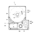
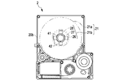
- Fig. 2 is a plan view of a tape cartridge according to a first embodiment when an upper case is partly omitted.
- Fig. 3A is a front-side perspective view of the tape cartridge.
- Fig. 3B is a back-side perspective view of the tape cartridge.
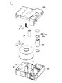
- Fig. 4 is an exploded perspective view of the tape cartridge.
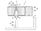
- Fig. 5A is a cross-sectional view of the tape cartridge taken along line V-V in Fig. 2.
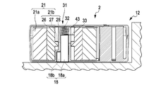
- Fig. 5B is a cross-sectional view of a cartridge mount.
- Fig. 6 is a plan view of a tape cartridge according to a second embodiment when an upper case is omitted.
- Fig. 7A is a plan view of a tape cartridge according to a third embodiment when an upper case is omitted.
- Fig. 7B is a plan view of a tape cartridge according to a modification of the third embodiment when an upper case
- a tape printer performs printing while a print tape and an ink ribbon are unwound from a mounted tape cartridge and simultaneously run with a tension applied to the print tape and the ink ribbon, and the tape printer cuts a printed portion of the print tape to create a label (tape piece).
- FIG. 1 is an external perspective view of the tape printer 1 when a lid is open.
- Fig. 2 is a plan view of a tape cartridge 2 with an upper case 25a partly omitted.
- the tape printer 1 includes a device body 10 that defines an outer shell; a cartridge mount 12 that is depressed at the inside of an open/close lid 11, the tape cartridge 2 that houses a print tape 21a etc. being removably mounted on the cartridge mount 12; a tape feeder 13 that feeds the print tape 21a by unwinding the print tape 21a from the tape cartridge 2; and a cutter 14 that cuts the print tape 21a after printing.
- a user operates a keyboard 15 that is arranged on an upper surface of the device body 10, and executes a print operation while the user checks a display 16 that displays the operation result etc.
- the tape cartridge 2 includes a tape unit 21 in which the print tape 21a is wound around a tape core 21b; a ribbon unit 22 in which an ink ribbon 22a is wound around a ribbon core 22b; a wind core 23 around which the used ink ribbon 22a is wound; and a platen roller 24 that unwinds and feeds the print tape 21a from the tape unit 21.
- the tape feeder 13 includes a plurality of driving shafts 17 that rotate the platen roller 24 and the wind core 23 to cause the print tape 21a and the ink ribbon 22a in the tape cartridge 2, which is mounted on the cartridge mount 12, to travel; a positioning protrusion 18 that engages with the tape core 21b and positions the tape core 21b; and a driving mechanism (not shown) that synchronously rotates the plurality of driving shafts 17.
- a thermal head 19 contacts the platen roller 24 with the print tape 21a and the ink ribbon 22a arranged therebetween, and the tape printer 1 is brought into a print standby state (see Fig. 2).
- the ink ribbon 22a and the print tape 21a run in a superposed manner at a portion of the platen roller 24.
- the print tape 21a after print processing by the thermal head 19 is sent to the outside of the tape cartridge 2 and the device body 10.
- the cutter 14 cuts the printed portion in a tape-width direction, and hence a tape piece (label) is created.
- the ink ribbon 22a is sent along a predetermined path in the tape cartridge 2, and is wound around the wind core 23.
- Figs. 3A and 3B are front-side and back-side perspective views of the tape cartridge 2.
- Fig. 4 is an exploded perspective view of the tape cartridge 2.
- Figs. 5A and 5B are a cross-sectional view of the tape cartridge 2 taken along line V-V in Fig. 2 and a cross-sectional view of the cartridge mount 12.
- An outer shell of the tape cartridge 2 is formed by a cartridge case 25 including an upper case 25a and a lower case 25b.
- the cartridge case 25 houses therein the above-described tape unit 21, ribbon unit 22, wind core 23, and platen roller 24.
- the upper case 25a and the lower case 25b are press-fitted and joined by a pin and a through hole formed in joint end surfaces (so as to be disassembled and reused).
- the tape core 21b of the tape unit 21 includes a core body 26 with a print tape 21a wound around an outer peripheral surface of the core body 26, a rib 27 that protrudes from a middle portion in an axial direction of an inner peripheral surface of the core body 26, and a shaft hole 28 that is formed at the axis center of the rib 27 (see Figs. 2, 5A, and 5B).
- the core body 26, the rib 27, and the shaft hole 28 are integrally formed.
- the core body 26 has a hollow cylindrical shape.
- the rib 27 has a hollow disk-like shape with the shaft hole 28 formed at the axis center thereof.
- a backstop mechanism 31 is arranged at an inner peripheral surface of the core body 26 (see Figs. 4, 5A, and 5B).
- the backstop mechanism 31 prevents an unwound end of the print tape 21a from being drawn into the cartridge case 25.
- the backstop mechanism 31 includes ratchet grooves (not shown) having sawtooth-like ratchet wheels that are formed at front and back surfaces of the rib 27 and allow only rotation in an unwinding direction of the print tape 21a, and a backstop spring 32 (i.e., coil spring) having both end portions that respectively contact the rib 27 and the upper case 25a and including a linear engagement portion 33 that linearly extends from a lower end portion of the backstop spring 32.
- the lower case 25b includes a shaft support 41 that is inserted into the shaft hole 28 and rotatably supports the tape core 21b, and a rotation guide 42 that is arranged with the shaft support 41 so as to slide on the inner peripheral surface of the core body 26.
- the shaft support 41 has a hollow cylindrical shape standing on the lower case 25b.
- a vertical groove 43 is formed from an upper end of the shaft support 41.
- the vertical groove 43 extends to a position lower than the position of the ratchet groove of the tape core 21b mounted at the shaft support 41 (see Fig. 5A).
- the backstop spring 32 when the backstop spring 32 is inserted into the inner periphery portion of the shaft support 41 while the linear engagement portion 33 is positioned with respect to the vertical groove 43, the linear engagement portion 33 is placed on the ratchet groove. Then, when the upper case 25a is mounted in this state, the backstop spring 32 is compressed, and the linear engagement portion 33 is pressed to the ratchet groove (see Fig. 5A). Hence, the tape core 21b is allowed to rotate in the unwinding direction of the print tape 21a (in a B direction in Fig. 2), and is inhibited from rotating in the reverse direction.
- the positioning protrusion 18 presses the backstop spring 32 from the lower side and disengages the linear engagement portion 33 from the ratchet groove (see Fig. 5B). That is, the linear engagement portion 33 is separated from the ratchet groove, and the tape core 21b becomes freely rotatable.
- the backstop spring 32 may have a structure that is mounted on an outer peripheral surface of the shaft support 41.
- the rotation guide 42 protrudes from the shaft support 41 at a proximal end portion of the shaft support 41.
- the rotation guide 42 is integrally molded with the lower case 25b and has a predetermined thickness.
- the rotation guide 42 is provided at a single position at the upper side in Fig. 2.
- the rotation guide 42 has a portion that slides on the inner peripheral surface of the core body 26 and that has a curvature radius substantially equivalent to the curvature radius of the inner peripheral surface. Hence, the rotation guide 42 does not disturb rotation of the tape core 21b.
- the tape core 21b when the tape core 21b is supported by the shaft hole 28 of the lower case 25b, the rib 27 of the core body 26 slides on the shaft support 41 and the rotation guide 42 slides on the inner peripheral surface of the core body 26.
- the tape core 21b is rotatably supported in the lower case 25b at two positions of the shaft support 41 and the rotation guide 42. Accordingly, the tape core 21b rotates without the "rattle" (without being inclined), and the phenomenon in which the print tape 21a wound around the tape core 21b is unwound while the print tape 21a is inclined can be prevented.
- a fit opening 44 is formed in a lower surface (back surface) of the lower case 25b (see Fig. 3B).
- the fit opening 44 includes a hollow portion 44a that serves as an inner peripheral surface of the shaft support 41, and a recess portion 44b defined by the rotation guide 42.
- the hollow portion 44a and the recess portion 44b are integrally formed.
- the positioning protrusion 18 that engages with the tape core 21b and positions the tape core 21b stands on the cartridge mount 12 (see Figs. 1, 5A, and 5B).
- the positioning protrusion 18 includes a fit shaft 18a and a fit protrusion 18b.
- the fit shaft 18a is fitted to the hollow portion 44a of the shaft support 41 and the fit protrusion 18b is fitted to the recess portion 44b by the rotation guide 42 when the tape cartridge 2 is mounted on the cartridge mount 12.
- the positioning protrusion 18 is fitted to the fit opening 44 at the lower surface of the lower case 25b, positions the tape cartridge 2 with respect to the cartridge mount 12, and fixes the tape cartridge 2 non-rotatably. Accordingly, the "rattle" of the tape cartridge 2 at the cartridge mount 12 can be eliminated, and the rotation of the tape core 21b provided in the tape cartridge 2 can be stabilized.
- the rib 27 and the rotation guide 42 can stabilize the rotation of the tape core 21b, and the print tape 21a wound around the tape core 21b can be properly unwound.
- the rotation guide 42 is arranged with the shaft support 41 and is integrally formed with the shaft support 41.
- the rotation guide 42 may be separately provided at a position apart from the shaft support 41.
- FIG. 6 is a plan view of the tape cartridge 2 according to the second embodiment when an upper case 25a is omitted.
- the tape cartridge 2 according to the second embodiment has a rotation guide 42 on a normal line at a position at which a print tape 21a is unwound. In this way, since the rotation guide 42 is provided at a portion on which a force that causes inclination acts the most (on which the largest force acts), the tape core 21b can be reliably prevented from being inclined, and rotation without the "rattle" can be assured.
- Fig. 7A is a plan view of a tape cartridge 2 according to a third embodiment. Description similar to that in the first embodiment will be omitted.
- the tape cartridge 2 includes a plurality of (in this embodiment, four) rotation guides 42 that are evenly arranged in a circumferential direction of a shaft support 41. In this case, the number and positions of the rotation guides 42 are desirably determined. With this configuration, the inclination of the tape core 21b in a plurality of directions can be prevented, and the "rattle" of the tape core 21b can be reliably prevented.
- Fig. 7B is a plan view of a tape cartridge 2 according to a modification of the third embodiment.
- the tape cartridge 2 includes a rotation guide 42 that extends over the entire circumference of a shaft support 41.
Landscapes
- Impression-Transfer Materials And Handling Thereof (AREA)
- Printers Characterized By Their Purpose (AREA)
- Handling Of Continuous Sheets Of Paper (AREA)
- Replacement Of Web Rolls (AREA)
- Basic Packing Technique (AREA)
Priority Applications (8)
| Application Number | Priority Date | Filing Date | Title |
|---|---|---|---|
| KR1020147018737A KR101664095B1 (ko) | 2010-06-25 | 2011-06-21 | 테이프 카트리지 |
| RU2013103369/12A RU2543424C2 (ru) | 2010-06-25 | 2011-06-21 | Ленточный картридж и ленточное печатающее устройство |
| KR1020137001932A KR101421118B1 (ko) | 2010-06-25 | 2011-06-21 | 테이프 카트리지 및 테이프 프린터 |
| US13/805,313 US8974131B2 (en) | 2010-06-25 | 2011-06-21 | Tape catridge and tape printer |
| EP11740732.0A EP2585306B1 (en) | 2010-06-25 | 2011-06-21 | Tape cartridge and tape printer |
| KR1020147003878A KR101473800B1 (ko) | 2010-06-25 | 2011-06-21 | 테이프 카트리지 및 테이프 인쇄 장치 |
| US14/593,378 US9327531B2 (en) | 2010-06-25 | 2015-01-09 | Tape cartridge with open area for preventing rotation in cartridge mount |
| US15/087,964 US10022990B2 (en) | 2010-06-25 | 2016-03-31 | Tape cartridge and tape printer |
Applications Claiming Priority (2)
| Application Number | Priority Date | Filing Date | Title |
|---|---|---|---|
| JP2010145005A JP5556435B2 (ja) | 2010-06-25 | 2010-06-25 | テープカートリッジ |
| JP2010-145005 | 2010-06-25 |
Related Child Applications (2)
| Application Number | Title | Priority Date | Filing Date |
|---|---|---|---|
| US13/805,313 A-371-Of-International US8974131B2 (en) | 2010-06-25 | 2011-06-21 | Tape catridge and tape printer |
| US14/593,378 Continuation US9327531B2 (en) | 2010-06-25 | 2015-01-09 | Tape cartridge with open area for preventing rotation in cartridge mount |
Publications (1)
| Publication Number | Publication Date |
|---|---|
| WO2011161955A1 true WO2011161955A1 (en) | 2011-12-29 |
Family
ID=44629622
Family Applications (1)
| Application Number | Title | Priority Date | Filing Date |
|---|---|---|---|
| PCT/JP2011/003541 WO2011161955A1 (en) | 2010-06-25 | 2011-06-21 | Tape cartridge and tape printer |
Country Status (8)
Cited By (1)
| Publication number | Priority date | Publication date | Assignee | Title |
|---|---|---|---|---|
| EP3181370A4 (en) * | 2014-09-30 | 2018-02-14 | Seiko Epson Corporation | Tape cartridge |
Families Citing this family (23)
| Publication number | Priority date | Publication date | Assignee | Title |
|---|---|---|---|---|
| JP5556435B2 (ja) | 2010-06-25 | 2014-07-23 | セイコーエプソン株式会社 | テープカートリッジ |
| JP6015266B2 (ja) * | 2012-09-13 | 2016-10-26 | コクヨ株式会社 | 転写具及び転写具のリフィル |
| WO2014148061A1 (ja) * | 2013-03-21 | 2014-09-25 | セイコーエプソン株式会社 | テープカートリッジおよびテープ印刷装置 |
| JP6172457B2 (ja) * | 2013-10-31 | 2017-08-02 | ブラザー工業株式会社 | テープカートリッジ |
| JP6346766B2 (ja) | 2014-03-24 | 2018-06-20 | セイコーエプソン株式会社 | テープカートリッジ |
| JP6113207B2 (ja) | 2014-03-24 | 2017-04-12 | セイコーエプソン株式会社 | テープカートリッジ |
| EP3124258B1 (en) * | 2014-03-24 | 2019-04-17 | Seiko Epson Corporation | Tape printing device and tape printing system |
| JP6381941B2 (ja) * | 2014-03-24 | 2018-08-29 | セイコーエプソン株式会社 | テープカートリッジ |
| JP6218657B2 (ja) * | 2014-03-24 | 2017-10-25 | セイコーエプソン株式会社 | テープカートリッジ |
| JP6144221B2 (ja) * | 2014-03-24 | 2017-06-07 | セイコーエプソン株式会社 | テープカートリッジ |
| JP5876125B2 (ja) * | 2014-09-19 | 2016-03-02 | セイコーエプソン株式会社 | テープカートリッジ |
| JP6508904B2 (ja) * | 2014-09-30 | 2019-05-08 | セイコーエプソン株式会社 | テープカートリッジ |
| JP6397719B2 (ja) * | 2014-10-16 | 2018-09-26 | セイコーエプソン株式会社 | テープカートリッジ |
| JP6561492B2 (ja) * | 2015-02-23 | 2019-08-21 | セイコーエプソン株式会社 | テープ印刷装置およびテープ印刷システム |
| JP6297514B2 (ja) * | 2015-03-19 | 2018-03-20 | セイコーエプソン株式会社 | テープカートリッジ |
| JP6509006B2 (ja) * | 2015-03-30 | 2019-05-08 | セイコーエプソン株式会社 | テープカートリッジ |
| JP6561750B2 (ja) | 2015-09-15 | 2019-08-21 | セイコーエプソン株式会社 | テープカートリッジ |
| FI4324655T3 (fi) * | 2018-03-29 | 2025-08-05 | Seiko Epson Corp | Nauhakasetti ja tulostuslaite |
| CN115447290B (zh) * | 2018-03-29 | 2023-11-03 | 精工爱普生株式会社 | 色带盒 |
| JP6535796B2 (ja) * | 2018-08-03 | 2019-06-26 | セイコーエプソン株式会社 | テープカートリッジ |
| CN111376620B (zh) * | 2018-12-26 | 2022-04-29 | 精工爱普生株式会社 | 装配于带印刷装置的盒 |
| JP7456204B2 (ja) * | 2020-03-11 | 2024-03-27 | セイコーエプソン株式会社 | カートリッジ |
| JP2024047408A (ja) * | 2022-09-26 | 2024-04-05 | セイコーエプソン株式会社 | テープカートリッジ、テープロールおよびテープカートリッジセット |
Citations (5)
| Publication number | Priority date | Publication date | Assignee | Title |
|---|---|---|---|---|
| EP0635375A2 (en) * | 1993-07-23 | 1995-01-25 | Brother Kogyo Kabushiki Kaisha | Tape unit and tape printer |
| JPH1071756A (ja) | 1997-08-21 | 1998-03-17 | Seiko Epson Corp | 印字テープカートリッジ |
| EP0958931A2 (en) * | 1992-10-13 | 1999-11-24 | Seiko Epson Corporation | Tape cartridge and printing device |
| JP2000103129A (ja) * | 1998-09-28 | 2000-04-11 | Brother Ind Ltd | テープカセット |
| EP1329327A1 (en) * | 2000-10-19 | 2003-07-23 | Brother Kogyo Kabushiki Kaisha | Tape cassette and tape unit |
Family Cites Families (20)
| Publication number | Priority date | Publication date | Assignee | Title |
|---|---|---|---|---|
| JP2985911B2 (ja) | 1992-01-08 | 1999-12-06 | ブラザー工業株式会社 | テープ印字装置におけるテープカセット装着構造 |
| JP2927146B2 (ja) | 1993-06-15 | 1999-07-28 | ブラザー工業株式会社 | テープカセット |
| JP3478598B2 (ja) * | 1994-05-25 | 2003-12-15 | ブラザー工業株式会社 | テープカセット |
| JP3031450B2 (ja) | 1994-07-21 | 2000-04-10 | ブラザー工業株式会社 | 印字用カセット |
| JP3968130B2 (ja) * | 1994-08-09 | 2007-08-29 | セイコーエプソン株式会社 | テープカートリッジ |
| JP3333324B2 (ja) * | 1994-08-23 | 2002-10-15 | セイコーエプソン株式会社 | テープカートリッジおよびテープ印字装置 |
| JP3113532B2 (ja) * | 1994-12-28 | 2000-12-04 | アルプス電気株式会社 | テープカセット |
| JPH0939346A (ja) * | 1995-08-02 | 1997-02-10 | Fujicopian Co Ltd | インクリボンカセット |
| US5685656A (en) * | 1995-10-19 | 1997-11-11 | Brother Kogyo Kabushiki Kaisha | Tape-shaped label printing device having color range setting means |
| JP3610158B2 (ja) * | 1996-04-05 | 2005-01-12 | セイコーエプソン株式会社 | テープリール装置およびこれを備えたテープカートリッジ |
| DE69727580T2 (de) * | 1997-11-27 | 2004-07-08 | Esselte N.V. | Nachfüllbare Farbbandkassette |
| JP3610782B2 (ja) | 1998-08-24 | 2005-01-19 | セイコーエプソン株式会社 | テープカートリッジおよびこれを備えたテープ印刷装置 |
| JP3815266B2 (ja) * | 2001-06-27 | 2006-08-30 | カシオ計算機株式会社 | 印字装置 |
| JP3753697B2 (ja) * | 2003-01-16 | 2006-03-08 | セイコーエプソン株式会社 | テープカートリッジ |
| JP2005329569A (ja) * | 2004-05-18 | 2005-12-02 | Seiko Epson Corp | カートリッジ |
| EP1799459B1 (en) * | 2004-07-30 | 2017-04-05 | Dymo | Cassette locking and ejecting arrangement |
| JP2006069789A (ja) * | 2004-09-06 | 2006-03-16 | Brother Ind Ltd | ロール状印刷媒体保持装置 |
| JP2006116823A (ja) * | 2004-10-21 | 2006-05-11 | Seiko Epson Corp | テープカートリッジおよびこれが着脱自在に装着されるテープ処理装置 |
| CN201483902U (zh) * | 2009-08-04 | 2010-05-26 | 广州广电运通金融电子股份有限公司 | 一种凭条打印装置 |
| JP5556435B2 (ja) | 2010-06-25 | 2014-07-23 | セイコーエプソン株式会社 | テープカートリッジ |
-
2010
- 2010-06-25 JP JP2010145005A patent/JP5556435B2/ja active Active
-
2011
- 2011-06-21 KR KR1020137001932A patent/KR101421118B1/ko not_active Expired - Fee Related
- 2011-06-21 WO PCT/JP2011/003541 patent/WO2011161955A1/en active Application Filing
- 2011-06-21 KR KR1020147018737A patent/KR101664095B1/ko active Active
- 2011-06-21 US US13/805,313 patent/US8974131B2/en active Active
- 2011-06-21 KR KR1020147003878A patent/KR101473800B1/ko active Active
- 2011-06-21 RU RU2013103369/12A patent/RU2543424C2/ru active
- 2011-06-21 EP EP11740732.0A patent/EP2585306B1/en active Active
- 2011-06-22 TW TW100121881A patent/TWI430894B/zh not_active IP Right Cessation
- 2011-06-22 TW TW103102569A patent/TWI556982B/zh active
- 2011-06-22 TW TW105130393A patent/TWI655101B/zh not_active IP Right Cessation
- 2011-06-22 CN CN201310727219.7A patent/CN103818128B/zh not_active Expired - Fee Related
- 2011-06-22 CN CN201110169424.7A patent/CN102295197B/zh active Active
-
2015
- 2015-01-09 US US14/593,378 patent/US9327531B2/en not_active Expired - Fee Related
-
2016
- 2016-03-31 US US15/087,964 patent/US10022990B2/en not_active Expired - Fee Related
Patent Citations (5)
| Publication number | Priority date | Publication date | Assignee | Title |
|---|---|---|---|---|
| EP0958931A2 (en) * | 1992-10-13 | 1999-11-24 | Seiko Epson Corporation | Tape cartridge and printing device |
| EP0635375A2 (en) * | 1993-07-23 | 1995-01-25 | Brother Kogyo Kabushiki Kaisha | Tape unit and tape printer |
| JPH1071756A (ja) | 1997-08-21 | 1998-03-17 | Seiko Epson Corp | 印字テープカートリッジ |
| JP2000103129A (ja) * | 1998-09-28 | 2000-04-11 | Brother Ind Ltd | テープカセット |
| EP1329327A1 (en) * | 2000-10-19 | 2003-07-23 | Brother Kogyo Kabushiki Kaisha | Tape cassette and tape unit |
Cited By (1)
| Publication number | Priority date | Publication date | Assignee | Title |
|---|---|---|---|---|
| EP3181370A4 (en) * | 2014-09-30 | 2018-02-14 | Seiko Epson Corporation | Tape cartridge |
Also Published As
| Publication number | Publication date |
|---|---|
| RU2013103369A (ru) | 2014-07-27 |
| US8974131B2 (en) | 2015-03-10 |
| US9327531B2 (en) | 2016-05-03 |
| KR20140102281A (ko) | 2014-08-21 |
| TWI655101B (zh) | 2019-04-01 |
| US20150124041A1 (en) | 2015-05-07 |
| TW201418045A (zh) | 2014-05-16 |
| TWI556982B (zh) | 2016-11-11 |
| TWI430894B (zh) | 2014-03-21 |
| TW201210850A (en) | 2012-03-16 |
| CN103818128A (zh) | 2014-05-28 |
| EP2585306A1 (en) | 2013-05-01 |
| JP5556435B2 (ja) | 2014-07-23 |
| US10022990B2 (en) | 2018-07-17 |
| EP2585306B1 (en) | 2019-09-18 |
| KR101421118B1 (ko) | 2014-07-18 |
| CN103818128B (zh) | 2017-04-12 |
| US20130089366A1 (en) | 2013-04-11 |
| KR101473800B1 (ko) | 2014-12-24 |
| RU2543424C2 (ru) | 2015-02-27 |
| US20160214416A1 (en) | 2016-07-28 |
| CN102295197A (zh) | 2011-12-28 |
| JP2012006295A (ja) | 2012-01-12 |
| KR20140038551A (ko) | 2014-03-28 |
| KR20130059388A (ko) | 2013-06-05 |
| KR101664095B1 (ko) | 2016-10-10 |
| CN102295197B (zh) | 2015-03-18 |
| TW201704043A (zh) | 2017-02-01 |
Similar Documents
| Publication | Publication Date | Title |
|---|---|---|
| US10022990B2 (en) | Tape cartridge and tape printer | |
| US9908347B2 (en) | Tape cartridge and tape printer | |
| JP5565639B2 (ja) | ロールテープ及び印字装置 | |
| EP1918117B1 (en) | Rolled sheet support mechanism and printer | |
| USRE40202E1 (en) | Ink ribbon cassette for thermal transfer printer | |
| US20170190195A1 (en) | Tape cartridge | |
| US20180079239A1 (en) | Tape cartridge | |
| WO2011030579A1 (ja) | テープカセット | |
| JP4373174B2 (ja) | リボンカセット | |
| JP5876125B2 (ja) | テープカートリッジ | |
| JP2012030433A (ja) | テープカセット | |
| JP2007118236A (ja) | テープリール装置およびこれを備えたテープカートリッジ | |
| JP2007118507A (ja) | テープカートリッジ |
Legal Events
| Date | Code | Title | Description |
|---|---|---|---|
| 121 | Ep: the epo has been informed by wipo that ep was designated in this application |
Ref document number: 11740732 Country of ref document: EP Kind code of ref document: A1 |
|
| WWE | Wipo information: entry into national phase |
Ref document number: 9851/DELNP/2012 Country of ref document: IN |
|
| WWE | Wipo information: entry into national phase |
Ref document number: 2011740732 Country of ref document: EP |
|
| WWE | Wipo information: entry into national phase |
Ref document number: 13805313 Country of ref document: US |
|
| NENP | Non-entry into the national phase |
Ref country code: DE |
|
| ENP | Entry into the national phase |
Ref document number: 20137001932 Country of ref document: KR Kind code of ref document: A |
|
| ENP | Entry into the national phase |
Ref document number: 2013103369 Country of ref document: RU Kind code of ref document: A |