WO2011158746A1 - ヒューズユニット、型構造及び型構造を用いた成形方法 - Google Patents
ヒューズユニット、型構造及び型構造を用いた成形方法 Download PDFInfo
- Publication number
- WO2011158746A1 WO2011158746A1 PCT/JP2011/063348 JP2011063348W WO2011158746A1 WO 2011158746 A1 WO2011158746 A1 WO 2011158746A1 JP 2011063348 W JP2011063348 W JP 2011063348W WO 2011158746 A1 WO2011158746 A1 WO 2011158746A1
- Authority
- WO
- WIPO (PCT)
- Prior art keywords
- mold
- terminal
- tuning fork
- bus bar
- terminal base
- Prior art date
- Legal status (The legal status is an assumption and is not a legal conclusion. Google has not performed a legal analysis and makes no representation as to the accuracy of the status listed.)
- Ceased
Links
Images





Classifications
-
- H—ELECTRICITY
- H01—ELECTRIC ELEMENTS
- H01R—ELECTRICALLY-CONDUCTIVE CONNECTIONS; STRUCTURAL ASSOCIATIONS OF A PLURALITY OF MUTUALLY-INSULATED ELECTRICAL CONNECTING ELEMENTS; COUPLING DEVICES; CURRENT COLLECTORS
- H01R43/00—Apparatus or processes specially adapted for manufacturing, assembling, maintaining, or repairing of line connectors or current collectors or for joining electric conductors
- H01R43/20—Apparatus or processes specially adapted for manufacturing, assembling, maintaining, or repairing of line connectors or current collectors or for joining electric conductors for assembling or disassembling contact members with insulating base, case or sleeve
- H01R43/24—Assembling by moulding on contact members
-
- H—ELECTRICITY
- H01—ELECTRIC ELEMENTS
- H01H—ELECTRIC SWITCHES; RELAYS; SELECTORS; EMERGENCY PROTECTIVE DEVICES
- H01H85/00—Protective devices in which the current flows through a part of fusible material and this current is interrupted by displacement of the fusible material when this current becomes excessive
- H01H85/02—Details
- H01H85/04—Fuses, i.e. expendable parts of the protective device, e.g. cartridges
- H01H85/041—Fuses, i.e. expendable parts of the protective device, e.g. cartridges characterised by the type
- H01H85/044—General constructions or structure of low voltage fuses, i.e. below 1000 V, or of fuses where the applicable voltage is not specified
- H01H85/045—General constructions or structure of low voltage fuses, i.e. below 1000 V, or of fuses where the applicable voltage is not specified cartridge type
-
- B—PERFORMING OPERATIONS; TRANSPORTING
- B29—WORKING OF PLASTICS; WORKING OF SUBSTANCES IN A PLASTIC STATE IN GENERAL
- B29C—SHAPING OR JOINING OF PLASTICS; SHAPING OF MATERIAL IN A PLASTIC STATE, NOT OTHERWISE PROVIDED FOR; AFTER-TREATMENT OF THE SHAPED PRODUCTS, e.g. REPAIRING
- B29C45/00—Injection moulding, i.e. forcing the required volume of moulding material through a nozzle into a closed mould; Apparatus therefor
- B29C45/03—Injection moulding apparatus
- B29C45/04—Injection moulding apparatus using movable moulds or mould halves
-
- B—PERFORMING OPERATIONS; TRANSPORTING
- B29—WORKING OF PLASTICS; WORKING OF SUBSTANCES IN A PLASTIC STATE IN GENERAL
- B29C—SHAPING OR JOINING OF PLASTICS; SHAPING OF MATERIAL IN A PLASTIC STATE, NOT OTHERWISE PROVIDED FOR; AFTER-TREATMENT OF THE SHAPED PRODUCTS, e.g. REPAIRING
- B29C45/00—Injection moulding, i.e. forcing the required volume of moulding material through a nozzle into a closed mould; Apparatus therefor
- B29C45/14—Injection moulding, i.e. forcing the required volume of moulding material through a nozzle into a closed mould; Apparatus therefor incorporating preformed parts or layers, e.g. injection moulding around inserts or for coating articles
- B29C45/14008—Inserting articles into the mould
-
- B—PERFORMING OPERATIONS; TRANSPORTING
- B29—WORKING OF PLASTICS; WORKING OF SUBSTANCES IN A PLASTIC STATE IN GENERAL
- B29C—SHAPING OR JOINING OF PLASTICS; SHAPING OF MATERIAL IN A PLASTIC STATE, NOT OTHERWISE PROVIDED FOR; AFTER-TREATMENT OF THE SHAPED PRODUCTS, e.g. REPAIRING
- B29C45/00—Injection moulding, i.e. forcing the required volume of moulding material through a nozzle into a closed mould; Apparatus therefor
- B29C45/14—Injection moulding, i.e. forcing the required volume of moulding material through a nozzle into a closed mould; Apparatus therefor incorporating preformed parts or layers, e.g. injection moulding around inserts or for coating articles
- B29C45/14065—Positioning or centering articles in the mould
-
- B—PERFORMING OPERATIONS; TRANSPORTING
- B29—WORKING OF PLASTICS; WORKING OF SUBSTANCES IN A PLASTIC STATE IN GENERAL
- B29C—SHAPING OR JOINING OF PLASTICS; SHAPING OF MATERIAL IN A PLASTIC STATE, NOT OTHERWISE PROVIDED FOR; AFTER-TREATMENT OF THE SHAPED PRODUCTS, e.g. REPAIRING
- B29C45/00—Injection moulding, i.e. forcing the required volume of moulding material through a nozzle into a closed mould; Apparatus therefor
- B29C45/14—Injection moulding, i.e. forcing the required volume of moulding material through a nozzle into a closed mould; Apparatus therefor incorporating preformed parts or layers, e.g. injection moulding around inserts or for coating articles
- B29C45/14467—Joining articles or parts of a single article
-
- H—ELECTRICITY
- H01—ELECTRIC ELEMENTS
- H01H—ELECTRIC SWITCHES; RELAYS; SELECTORS; EMERGENCY PROTECTIVE DEVICES
- H01H69/00—Apparatus or processes for the manufacture of emergency protective devices
- H01H69/02—Manufacture of fuses
-
- H—ELECTRICITY
- H01—ELECTRIC ELEMENTS
- H01H—ELECTRIC SWITCHES; RELAYS; SELECTORS; EMERGENCY PROTECTIVE DEVICES
- H01H85/00—Protective devices in which the current flows through a part of fusible material and this current is interrupted by displacement of the fusible material when this current becomes excessive
- H01H85/02—Details
- H01H85/04—Fuses, i.e. expendable parts of the protective device, e.g. cartridges
-
- H—ELECTRICITY
- H01—ELECTRIC ELEMENTS
- H01H—ELECTRIC SWITCHES; RELAYS; SELECTORS; EMERGENCY PROTECTIVE DEVICES
- H01H85/00—Protective devices in which the current flows through a part of fusible material and this current is interrupted by displacement of the fusible material when this current becomes excessive
- H01H85/02—Details
- H01H85/04—Fuses, i.e. expendable parts of the protective device, e.g. cartridges
- H01H85/041—Fuses, i.e. expendable parts of the protective device, e.g. cartridges characterised by the type
- H01H85/044—General constructions or structure of low voltage fuses, i.e. below 1000 V, or of fuses where the applicable voltage is not specified
- H01H85/045—General constructions or structure of low voltage fuses, i.e. below 1000 V, or of fuses where the applicable voltage is not specified cartridge type
- H01H85/0456—General constructions or structure of low voltage fuses, i.e. below 1000 V, or of fuses where the applicable voltage is not specified cartridge type with knife-blade end contacts
-
- H—ELECTRICITY
- H01—ELECTRIC ELEMENTS
- H01H—ELECTRIC SWITCHES; RELAYS; SELECTORS; EMERGENCY PROTECTIVE DEVICES
- H01H85/00—Protective devices in which the current flows through a part of fusible material and this current is interrupted by displacement of the fusible material when this current becomes excessive
- H01H85/02—Details
- H01H85/04—Fuses, i.e. expendable parts of the protective device, e.g. cartridges
- H01H85/05—Component parts thereof
- H01H85/055—Fusible members
- H01H85/08—Fusible members characterised by the shape or form of the fusible member
- H01H85/10—Fusible members characterised by the shape or form of the fusible member with constriction for localised fusing
-
- H—ELECTRICITY
- H01—ELECTRIC ELEMENTS
- H01H—ELECTRIC SWITCHES; RELAYS; SELECTORS; EMERGENCY PROTECTIVE DEVICES
- H01H85/00—Protective devices in which the current flows through a part of fusible material and this current is interrupted by displacement of the fusible material when this current becomes excessive
- H01H85/02—Details
- H01H85/04—Fuses, i.e. expendable parts of the protective device, e.g. cartridges
- H01H85/05—Component parts thereof
- H01H85/165—Casings
- H01H85/175—Casings characterised by the casing shape or form
-
- H—ELECTRICITY
- H01—ELECTRIC ELEMENTS
- H01R—ELECTRICALLY-CONDUCTIVE CONNECTIONS; STRUCTURAL ASSOCIATIONS OF A PLURALITY OF MUTUALLY-INSULATED ELECTRICAL CONNECTING ELEMENTS; COUPLING DEVICES; CURRENT COLLECTORS
- H01R13/00—Details of coupling devices of the kinds covered by groups H01R12/70 or H01R24/00 - H01R33/00
- H01R13/02—Contact members
- H01R13/10—Sockets for co-operation with pins or blades
- H01R13/11—Resilient sockets
- H01R13/112—Resilient sockets forked sockets having two legs
-
- H—ELECTRICITY
- H01—ELECTRIC ELEMENTS
- H01R—ELECTRICALLY-CONDUCTIVE CONNECTIONS; STRUCTURAL ASSOCIATIONS OF A PLURALITY OF MUTUALLY-INSULATED ELECTRICAL CONNECTING ELEMENTS; COUPLING DEVICES; CURRENT COLLECTORS
- H01R25/00—Coupling parts adapted for simultaneous co-operation with two or more identical counterparts, e.g. for distributing energy to two or more circuits
- H01R25/14—Rails or bus-bars constructed so that the counterparts can be connected thereto at any point along their length
-
- H—ELECTRICITY
- H01—ELECTRIC ELEMENTS
- H01R—ELECTRICALLY-CONDUCTIVE CONNECTIONS; STRUCTURAL ASSOCIATIONS OF A PLURALITY OF MUTUALLY-INSULATED ELECTRICAL CONNECTING ELEMENTS; COUPLING DEVICES; CURRENT COLLECTORS
- H01R43/00—Apparatus or processes specially adapted for manufacturing, assembling, maintaining, or repairing of line connectors or current collectors or for joining electric conductors
- H01R43/16—Apparatus or processes specially adapted for manufacturing, assembling, maintaining, or repairing of line connectors or current collectors or for joining electric conductors for manufacturing contact members, e.g. by punching and by bending
-
- B—PERFORMING OPERATIONS; TRANSPORTING
- B29—WORKING OF PLASTICS; WORKING OF SUBSTANCES IN A PLASTIC STATE IN GENERAL
- B29C—SHAPING OR JOINING OF PLASTICS; SHAPING OF MATERIAL IN A PLASTIC STATE, NOT OTHERWISE PROVIDED FOR; AFTER-TREATMENT OF THE SHAPED PRODUCTS, e.g. REPAIRING
- B29C45/00—Injection moulding, i.e. forcing the required volume of moulding material through a nozzle into a closed mould; Apparatus therefor
- B29C45/14—Injection moulding, i.e. forcing the required volume of moulding material through a nozzle into a closed mould; Apparatus therefor incorporating preformed parts or layers, e.g. injection moulding around inserts or for coating articles
- B29C2045/1486—Details, accessories and auxiliary operations
-
- B—PERFORMING OPERATIONS; TRANSPORTING
- B29—WORKING OF PLASTICS; WORKING OF SUBSTANCES IN A PLASTIC STATE IN GENERAL
- B29C—SHAPING OR JOINING OF PLASTICS; SHAPING OF MATERIAL IN A PLASTIC STATE, NOT OTHERWISE PROVIDED FOR; AFTER-TREATMENT OF THE SHAPED PRODUCTS, e.g. REPAIRING
- B29C45/00—Injection moulding, i.e. forcing the required volume of moulding material through a nozzle into a closed mould; Apparatus therefor
- B29C45/03—Injection moulding apparatus
- B29C45/04—Injection moulding apparatus using movable moulds or mould halves
- B29C45/0441—Injection moulding apparatus using movable moulds or mould halves involving a rotational movement
- B29C45/045—Injection moulding apparatus using movable moulds or mould halves involving a rotational movement mounted on the circumference of a rotating support having a rotating axis perpendicular to the mould opening, closing or clamping direction
-
- B—PERFORMING OPERATIONS; TRANSPORTING
- B29—WORKING OF PLASTICS; WORKING OF SUBSTANCES IN A PLASTIC STATE IN GENERAL
- B29C—SHAPING OR JOINING OF PLASTICS; SHAPING OF MATERIAL IN A PLASTIC STATE, NOT OTHERWISE PROVIDED FOR; AFTER-TREATMENT OF THE SHAPED PRODUCTS, e.g. REPAIRING
- B29C45/00—Injection moulding, i.e. forcing the required volume of moulding material through a nozzle into a closed mould; Apparatus therefor
- B29C45/14—Injection moulding, i.e. forcing the required volume of moulding material through a nozzle into a closed mould; Apparatus therefor incorporating preformed parts or layers, e.g. injection moulding around inserts or for coating articles
-
- B—PERFORMING OPERATIONS; TRANSPORTING
- B29—WORKING OF PLASTICS; WORKING OF SUBSTANCES IN A PLASTIC STATE IN GENERAL
- B29L—INDEXING SCHEME ASSOCIATED WITH SUBCLASS B29C, RELATING TO PARTICULAR ARTICLES
- B29L2031/00—Other particular articles
- B29L2031/34—Electrical apparatus, e.g. sparking plugs or parts thereof
- B29L2031/3493—Moulded interconnect devices, i.e. moulded articles provided with integrated circuit traces
-
- B—PERFORMING OPERATIONS; TRANSPORTING
- B29—WORKING OF PLASTICS; WORKING OF SUBSTANCES IN A PLASTIC STATE IN GENERAL
- B29L—INDEXING SCHEME ASSOCIATED WITH SUBCLASS B29C, RELATING TO PARTICULAR ARTICLES
- B29L2031/00—Other particular articles
- B29L2031/34—Electrical apparatus, e.g. sparking plugs or parts thereof
- B29L2031/36—Plugs, connectors, or parts thereof
-
- H—ELECTRICITY
- H01—ELECTRIC ELEMENTS
- H01H—ELECTRIC SWITCHES; RELAYS; SELECTORS; EMERGENCY PROTECTIVE DEVICES
- H01H85/00—Protective devices in which the current flows through a part of fusible material and this current is interrupted by displacement of the fusible material when this current becomes excessive
- H01H85/02—Details
- H01H85/0241—Structural association of a fuse and another component or apparatus
- H01H2085/025—Structural association with a binding post of a storage battery
Definitions
- the present invention relates to a mold structure used for manufacturing an electrical component such as a fusible link unit by insert molding a bus bar, a molding method using the mold structure, and a fuse unit.
- a fusible link unit connects an in-vehicle battery and an electric wire that supplies power to an in-vehicle load, and is mounted on a part that is affected by body vibration.
- the part affected by the vibration of the vehicle body is manufactured by injecting the resin in a state where the bus bar in which the main body circuit portion is formed is inserted into the mold in consideration of breakage of the unit main body and the bus bar due to resonance. Since the bus bar and the resin molded product are integrated by insert-molding the bus bar in this way, resonance due to vibration can be suppressed.
- a tuning fork terminal formed into a tuning fork shape may be provided on the bus bar.
- the tuning fork terminal acts to make an electrical connection with the external terminal by inserting an external terminal such as an external fuse in a contact state, and must be exposed to the outside of the resin molded product. It has become indispensable.
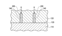
- reference numeral 110 is a fixed mold
- reference numeral 120 is a movable mold.
- the molds 110 and 120 are mold-matched (clamped) with the bus bar set between the molds 110 and 120. A cavity is formed, and resin is injected into the cavity.
- an accommodation space 140 for accommodating the tuning fork terminal 200 is formed on the mold mating surface (parting surface) 130 side of the movable mold 120. Then, the bus bar is set on the fixed mold 110 so that the tuning fork terminal 200 is located at a position corresponding to the accommodation space 140, and the mold matching is performed after this setting. Since the tuning fork terminal 200 is accommodated in the accommodating space 140 by mold matching, the tuning fork terminal 200 is independent from the cavity and is not buried by the resin injected into the cavity. Therefore, the tuning fork terminal 200 can be exposed from the resin molded product.
- the tuning fork terminal 200 may come into contact with the inner surface of the mold (movable mold 120) during mold matching. Further, a pressing force indicated by an arrow R in FIG. 2 may act on the tuning fork terminal 200 due to the type matching. As a result, the tuning fork terminal 200 may be deformed and cause defective products.
- An object of the present invention is to provide a mold structure in which a tuning fork terminal is not deformed when a bus bar is insert-molded, and a molding method using the mold structure.
- a bus bar attached to the battery terminal and formed by pressing, and a tuning fork terminal including a pair of opposing clamping pieces that are held between the fuses and electrically connected to the fuses.
- One of the pair of sandwiching pieces is electrically connected to the bus bar, the other of the pair of sandwiching pieces is electrically connected to the outside, and the bus bar and the tuning fork terminal are
- the gist of the present invention is that the fuse unit is integrally molded with the holding pieces exposed.
- molding can be performed without using a slide mold, and the fuse terminal is held by the tuning fork terminal, so that it is not necessary to separately provide a fuse holder for holding the fuse.
- the bus bar may include a fusible body attached to the battery terminal, and the fusible body may be molded integrally with the bus bar and the tuning fork terminal.
- a mold structure in which a bus bar provided with a tuning fork-shaped tuning fork terminal in a main circuit part is integrally embedded together with molding of a resin molded product by a fixed mold and a movable mold. Is a cavity in which the main body circuit portion is disposed and resin is injected, and the main body circuit portion is embedded in the resin to form a cavity in which a resin molded product is formed together with the movable mold.
- a second mold main body part that is combined with the mold main body part to form the cavity together with the fixed mold, a terminal base abutting part that clamps a terminal base part of the tuning fork terminal together with the terminal base receiving part, and a receiver for the fixed mold A contact step that contacts the contact step; and
- the fixed mold and the movable mold in a combined state, the terminal base between the terminal base receiving portion and the terminal base abutting portion in a state in which the tuning fork terminal protrudes to the outside of the cavity.
- the gist of the present invention is a mold structure that holds
- the tuning fork terminal when the fixed mold and the movable mold are matched, the fixed receiving contact step and the movable contact step are brought into contact with each other, and the terminal base formed in the fixed mold
- the terminal base of the tuning fork terminal is sandwiched between the receiving part and the terminal base contact part formed in a movable manner.
- the tuning fork terminal is positioned and fixed with respect to the fixed type and the movable type. In such a state where the tuning fork terminal is sandwiched, the tuning fork terminal protrudes from the cavity formed by combining the fixed and movable mold body portions. The terminal can be exposed from the resin molded product.
- the tuning fork terminal protrudes outside the cavity in the mold matching state, the tuning fork terminal is in a free state with respect to the fixed mold and the movable mold. Not only is there no contact, but the pressing force of the mold does not act. For this reason, the tuning fork terminal is not deformed, and it is possible to prevent the occurrence of defective products due to the deformation.
- the mold structure has a pair of holding pieces each having a bus bar end, an insertion opening of a mating terminal formed on each distal end side, and a slit formed continuously to the insertion opening, and is integrally formed from the bus bar end.
- the bus bar provided with the tuning fork terminal formed by the press-fitting contact portion extended to the embedment is embedded, and the fixed mold and the movable mold in the combined state include the pair of clamping pieces of the cavity. You may hold
- the clamping piece in the tuning fork terminal protrudes to the outside of the cavity, so that the entire tuning fork terminal is not exposed from the resin molded product, and part (the bus bar End) is embedded in the resin molded product. For this reason, the supporting force with respect to the tuning fork terminal of a resin molded product becomes large, and can give intensity
- a third aspect of the present invention is a molding method using a mold structure in which a bus bar having a tuning fork-shaped tuning fork terminal provided in a main body circuit portion is embedded together with molding of a resin molded product using a fixed mold and a movable mold. And the tuning fork terminal protrudes outside the cavity formed by combining the first mold body portion of the fixed mold and the second mold body portion of the movable mold.
- the receiving base is supported by the terminal base of the tuning fork terminal, the bus bar is set on the first mold body of the fixed mold, and the movable contact stage of the fixed mold
- the terminal base of the tuning fork terminal is sandwiched between the terminal base receiving part and the movable terminal base abutting part, the movable mold is matched with the fixed mold, and the clamped fork terminal is in the clamped state. It is a molding method that injects resin into the cavity. The gist of the door.
- the tuning fork terminal when the terminal base of the tuning fork terminal is supported by the fixed terminal base receiving part, the tuning fork terminal is outside the cavity formed by combining the fixed mold and the movable mold main body.
- the terminal base of the tuning fork terminal is clamped by the fixed terminal base receiving part and the movable terminal base abutting part during the subsequent mold matching.
- the tuning fork terminal is outside the cavity and is in a free state. For this reason, there is no contact with the mold, the pressing force of the mold does not act, the tuning fork terminal is not deformed, and insert molding can be performed while preventing the occurrence of defective products due to deformation. .
- FIG. 1 is a cross-sectional view from the side showing molding by a related mold structure.
- FIG. 2 is a cross-sectional view from the plane showing molding by the related mold structure.
- FIG. 3 is a perspective view of a bus bar applied to a mold structure according to an embodiment of the present invention. 4 shows the bus bar of FIG. 3, in which (a) is a plan view, (b) is a right side view, and (c) is a front view.
- FIG. 5 is a perspective view showing the main part of the mold structure according to one embodiment of the present invention.
- FIG. 6 is a cross-sectional view showing the main part of the mold structure.
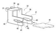
- FIG. 7 is a perspective view showing a tuning fork terminal of the bus bar.
- FIG. 8 is a perspective view showing a supported state of the tuning fork terminal during molding.
- FIG. 9 is a perspective view showing the support state of the tuning fork terminal during molding from the back side of FIG.
- FIG. 10 is a perspective view showing the molded electrical component.
- FIG. 11 shows a molded electrical component, where (a) is a plan view, (b) is a right side view, and (c) is a front view.
- FIG. 12 is a perspective view of a state where a fuse is attached to a molded electrical component.
- FIG. 13 is a perspective view of a state in which a lid is attached to a fuse portion of an electrical component.
- FIG. 3 to 13 show an embodiment of the present invention.
- 3 and 4 show a bus bar.
- 5 is a perspective view of the main part of the mold structure
- FIG. 6 is a cross-sectional view of the main part of the mold structure
- FIG. 7 is a perspective view of the bus bar
- FIGS. 8 and 9 are the tuning fork terminal support during molding.
- FIG. 10 and FIG. 11 show molded electrical components.
- 12 and 13 show perspective views of post-processing on the molded electrical component.
- the bus bar 3 applied to the mold structure 1 of this embodiment is formed by providing a tuning fork terminal 32 in the main body circuit portion 31.
- a power source side terminal plate 33 in which a power source side stud bolt hole 33 a is formed and a connection side terminal plate 34 in which a connection bolt hole 34 a is formed are connected by a fusible body portion 35.
- the fusible body portion 35 is melted when an excessive current flows from the power source side, and the melted portion 35 is designed to protect the load connected to the connection side terminal plate 34.
- the tuning fork terminal 32 is provided in a state of being connected to the power supply side terminal plate 33 side. As shown in FIGS. 4 and 7, the tuning fork terminal 32 includes a bus bar end 37 connected to the power supply side terminal plate 33 and a press-fit contact portion 38 extending from the bus bar end 37.
- the bus bar end 37 is formed by a horizontally long connecting portion 39 connected to the power supply side terminal plate 33 and a pair of left and right terminal base portions 40 bent integrally at right angles from both ends in the length direction of the connecting portion 39. ing.
- the press-fitting contact portion 38 includes a pair of sandwiching pieces 41 extending linearly from the respective terminal base portions 40.
- the pair of sandwiching pieces 41 extend so as to be parallel with each terminal base portion 40 in a state of facing each other.
- Each sandwiching piece 41 has a slit 42 extending in the length direction, and an extending end of the slit 42 is opened to form an insertion opening 43.
- a fuse 45 (see FIG. 12), which is a mating terminal, is inserted into the insertion opening 43, and the clamping piece 41 is pressed against the inserted fuse 45 from above and below, and the tuning fork terminal 32 (bus bar 3) and the fuse 45 are pressed by this pressure contact. And electrical connection is made.
- the mold structure 1 of this embodiment is to embed the above bus bar 3 integrally with the molding of the resin molded product by the fixed mold 4 (lower mold) and the movable mold 5 (upper mold).
- the fixed die 4 is formed with a die body (not shown) for setting the body circuit portion 31 of the bus bar 3.
- the movable mold 5 is formed with a mold main body (not shown) that faces the mold main body of the fixed mold 4 and forms a cavity for molding a resin molded product together with the mold main body of the fixed mold 4.
- the main body circuit portion 31 of the bus bar 3 is set in the die main body portions of these dies 4 and 5, the fixed die 4 and the movable die 5 are die-matched (clamping), and the resin is injected into the cavity to thereby inject the circuit main body portion. 31 is embedded in the resin integrally.
- a pair of bus bar set portions 11 for setting the terminal base portion 40 of the tuning fork terminal 32 is formed in the set portion of the tuning fork terminal 32 in the fixed mold 4.
- Each bus bar set part 11 has an open upper set groove 11 a into which the terminal base 40 is inserted.
- the tuning fork terminal 32 is attached to the fixed mold 4. It is designed to be positioned.
- the bus bar set part 11 is formed at a position close to the outer peripheral wall 12 (burr cutting part) of the fixed mold 4.
- the terminal base 40 is set on the bus bar set unit 11 as shown in FIGS. 5, 8, and 9.
- the pair of clamping pieces 41 of the tuning fork terminal 32 are attached to the fixed die 4 and the movable die 5. It is made to protrude in the direction.
- FIG. 5 the clamping piece 41 of the tuning fork terminal 32 is located on the movable mold 5 side, but FIG. 5 is shown to show the relationship between the terminal base contact portion 17 and the clamping piece 41 described later.
- the clamping piece 41 of the tuning fork terminal 32 is set on the bus bar set portion 11 of the fixed mold 4.
- the bus bar set 11 is formed upright in the fixed mold 4.
- the set groove 11a of the bus bar set portion 11 in the fixed mold 4 supports the terminal base portion 40 (the lower surface of the terminal base portion 40) when the terminal base portion 40 of the tuning fork terminal 32 comes into contact therewith.
- the movable die 5 has an outer peripheral surface 15 (burr cutting portion) that is flush with the outer peripheral wall 12 of the fixed die 4 by mold matching (see FIG. 8).
- a window portion 19 into which the outer peripheral wall 12 of the fixed mold 4 is fitted is formed in the movable mold 5 by mold matching.
- the window portion 19 is formed in a shape corresponding to the outer peripheral wall 12 of the fixed mold 4.
- a terminal base contact portion 17 corresponding to (facing) the terminal base receiving portion 13 of the fixed die 4 is formed on the outer peripheral wall 15 of the movable die 5.
- the terminal base abutment portion 17 abuts on the terminal base portion 40 (the upper surface of the terminal base portion 40) of the tuning fork terminal 32 supported by the terminal base portion receiving portion 13 (the set groove 11a of the bus bar set portion 11). By this contact, the terminal base 40 is sandwiched together with the set groove 11a.
- the receiving contact step 21 is formed on the fixed die 4, and the contact step 23 corresponding to the receiving contact step 21 is formed on the movable die 5.
- the receiving contact step portion 21 is formed by cutting out the vicinity of the bottom portion of the fixed mold 4 in a planar shape, and the formation site can be set at an appropriate position of the fixed mold 4.
- the contact step 23 is formed in the movable mold 5 so as to correspond to the receiving contact step 21.
- the contact step 23 of the movable mold 5 contacts the receiving contact step 21 of the fixed mold 4.
- a cavity is formed between the mold body portion of the movable mold 5 and the mold body portion of the fixed mold 4.
- the terminal base 40 of the tuning fork terminal 32 is held by the set groove 11a and the terminal base contact portion 17 described above.
- the main body circuit portion 31 of the bus bar 3 is set in the main body portion of the fixed die 4 in the mold open state.
- the terminal base portion 40 is inserted and set in the bus bar set portion 11 (set groove 11 a) of the fixed mold 4.
- the terminal base 40 of the tuning fork terminal 32 is supported by the terminal base receiving part 13 of the fixed mold 4 (the set groove 11a of the bus bar set part 11) by the setting to the bus bar set part 11.
- the pair of clamping pieces 41 of the tuning fork terminal 32 are arranged so as to protrude outward from the outer peripheral surface 12 of the fixed mold 4.
- the movable mold 5 is brought close to the fixed mold 4 to perform mold matching.
- the contact step 23 of the movable die 5 contacts the receiving contact step 21 of the fixed die 4 and the terminal base receiving portion 13 of the fixed die 4 (the set groove 11a of the bus bar set portion 11).
- the terminal base 40 of the tuning fork terminal 32 is sandwiched by the terminal base contact portion 17 of the movable mold 5.
- the clamping piece 41 of the tuning fork terminal 32 is held in a state of protruding outward from the mold body portions of the fixed mold 4 and the movable mold 5. That is, the clamping piece 41 of the tuning fork terminal 32 is in a free state outside the mold body portions of the fixed mold 4 and the movable mold 5.
- the molten resin is injected into the cavity formed by the mold body portions of the fixed mold 4 and the movable mold 5 while the terminal base 40 is held, and is cooled and cured. Accordingly, as shown in FIGS. 10 and 11, a fusible link unit or the like in which the main body circuit portion 31 of the bus bar 3 is embedded in the resin molded product 26 and the tuning fork terminal 32 is exposed to the outside from the resin molded product 26.
- the electrical component 25 is formed. 10 and 11, the stat bolt 47 protrudes upward from the resin molded product 26. However, the stat bolt 47 is attached to the bus bar 3 in advance so as to penetrate the connecting bolt hole 34a.
- FIG. 12 shows a state in which a fuse 45 as a counterpart terminal is attached to the electrical component 25.
- the fuse 45 is attached to the electrical component 25 in an electrically conductive state with the bus bar 3 by being inserted into the pair of clamping pieces 41 of the tuning fork terminal 32 exposed from the resin molded product 26.
- FIG. 13 shows a state in which the lid 45 is fixed to the mounting portion of the fuse 45 and the fuse 45 is protected.
- the tuning fork terminal 32 since the resin is injected with the pair of clamping pieces 41 of the tuning fork terminal 32 projecting outward from the mold body portions of the fixed mold 4 and the movable mold 5, the tuning fork terminal 32 is used.
- the clamping piece 41 is in a free state with respect to the fixed mold 4 and the movable mold 5. For this reason, not only the clamping piece 41 is not in contact with the fixed mold 4 and the movable mold 5, but also the pressing force of the mold does not act. Therefore, the tuning fork terminal 32 (clamping piece 41) is not deformed, and generation of defective products due to the deformation can be prevented.
- the tuning fork terminal 32 Since the tuning fork terminal 32 is positioned by setting the terminal base 40 of the tuning fork terminal 32 to the bus bar set unit 11, the tuning fork terminal 32 can be positioned with respect to the fixed mold 4 smoothly and accurately. In this case, the terminal base 40 is fixed to the fixed mold 4, and the clamping piece 41 on the distal end side of the terminal base 40 is in a free state. For this reason, the clamping piece 41 to which the fuse 45 is electrically connected does not deform.
- the resin molded product 26 Since the pinch piece 41 of the tuning fork terminal 32 protrudes outward from the mold main body portions of the fixed mold 4 and the movable mold 5, the resin molded product 26 is molded, and therefore the entire tuning fork terminal 32 may be exposed from the resin molded product 26. However, a part is embedded in the resin molded product 26. Thereby, the supporting force with respect to the tuning fork terminal 32 of the resin molded product 26 becomes large, and the strength can be imparted to the tuning fork terminal 32.
- the bus bar 3 having the power supply side terminal plate 33 and the connection type terminal plate 34 is used.
- the bus bar 3 may have another structure.
- the electrical component 25 is a fuse unit including a battery terminal or a bus bar having a fusible body attached to the battery terminal, and a pressure-contact type fuse terminal connected to the bus bar, and the bus bar in which the fusible body is formed is pressed.
- One set of tuning fork terminals to be molded and connected to the fuse is connected to the bus bar on one side, the other end has a terminal for external connection, and the pair of tuning fork terminals are arranged so as to sandwich the fuse terminal in the vertical direction
- this is an example of a fuse unit (fusible link unit; fuse block) that is integrally molded with the bus bar and the pair of tuning fork terminals and is attached to the battery terminal.
- this fuse unit molding can be performed without using a slide mold, and the fuse terminal is held by the tuning fork terminal, so that it is not necessary to separately provide a fuse holder for holding the fuse 45.
Landscapes
- Engineering & Computer Science (AREA)
- Manufacturing & Machinery (AREA)
- Mechanical Engineering (AREA)
- Moulds For Moulding Plastics Or The Like (AREA)
- Fuses (AREA)
- Connection Or Junction Boxes (AREA)
- Injection Moulding Of Plastics Or The Like (AREA)
Abstract
Description
Claims (5)
- バッテリー端子に取り付けられ、プレスにより成形されるバスバと、
ヒューズを挟んで保持して前記ヒューズと電気的に接続される対向する一対の挟持片を含む音叉端子と、を備え、
前記一対の挟持片の一方は、前記バスバに電気的に接続され、
前記一対の挟持片の他方は、外部に電気的に接続され、
前記バスバと前記音叉端子とは、前記一対の挟持片を露出した状態で一体的にモールドされている
ヒューズユニット。 - 前記バスバは、前記バッテリー端子に取り付けられる可溶体を含み、
前記可溶体は、前記バスバ及び前記音叉端子と一体的にモールドされている
請求項1記載のヒューズユニット - 本体回路部に音叉状の音叉端子が設けられたバスバを固定型と可動型とによる樹脂成形品の成形と共に一体に埋設する型構造であって、
前記固定型は、
内部に前記本体回路部が配置されて樹脂が射出されるキャビティであって、前記本体回路部が樹脂中に埋設されて樹脂成形品が成形されるキャビティを前記可動型と共に形成する第1の型本体部と、
前記音叉端子の端子基部を支持する端子基部受け部と、
前記可動型が当接する受け当接段部と、を有し、
前記可動型は、
前記固定型の第1の型本体部と合わさり、前記キャビティを前記固定型と共に形成する第2の型本体部と、
前記音叉端子の端子基部を前記端子基部受け部と共に挟持する端子基部当接部と、
前記固定型の受け当接段部と当接する当接段部と、を有し、
合わせ状態の前記固定型及び前記可動型は、前記音叉端子を前記キャビティの外部に突出させた状態で、前記端子基部受け部と前記端子基部当接部との間で前記端子基部を挟持する
型構造。 - 前記型構造は、バスバ端、それぞれの先端側に形成された相手端子の挿入開口と前記挿入開口に連続して形成されたスリットとを有する一対の挟持片を有するとともに前記バスバ端から一体に延設された圧入接触部、で形成された前記音叉端子が設けられた前記バスバを埋設するものであり、
合わせ状態の前記固定型及び前記可動型は、前記一対の挟持片を前記キャビティの外部に突出させた状態で保持する
請求項3記載の型構造。 - 本体回路部に音叉状の音叉端子が設けられたバスバを固定型と可動型とによる樹脂成形品の成形と共に一体に埋設する型構造を用いた成形方法であって、
前記固定型の第1の型本体部と前記可動型の第2の型本体部とが合わさって形成されるキャビティの外部に前記音叉端子を突出させた状態で、前記固定型の端子基部受け部に前記音叉端子の端子基部を支持させて、前記バスバを前記固定型の前記第1の型本体部にセットし、
前記固定型の受け当接段部に前記可動型の当接段部を当接させると共に、前記音叉端子の前記端子基部を前記端子基部受け部と前記可動型の端子基部当接部とによって挟持して、前記可動型を前記固定型に合わせ、
前記挟持状態で前記キャビティ内に樹脂を射出する
成形方法。
Priority Applications (7)
| Application Number | Priority Date | Filing Date | Title |
|---|---|---|---|
| KR1020127034107A KR101474313B1 (ko) | 2010-06-14 | 2011-06-10 | 퓨즈 유닛, 형 구조 및 형 구조를 사용한 성형 방법 |
| BR112012031712A BR112012031712A2 (pt) | 2010-06-14 | 2011-06-10 | unidade de fusível, estrutura matriz, e método de moldagem empregando a estrutura matriz |
| DE201111101992 DE112011101992T5 (de) | 2010-06-14 | 2011-06-10 | Sicherungseinheit, Formstruktur und Ausformungsverfahren unter Verwendung der Formstruktur |
| CN201180029344.XA CN102939637B (zh) | 2010-06-14 | 2011-06-10 | 熔断器单元、模具结构以及使用模具结构的模制方法 |
| US13/712,305 US9118129B2 (en) | 2010-06-14 | 2012-12-12 | Fuse unit, mold structure, and molding method using mold structure |
| US14/790,059 US9350132B2 (en) | 2010-06-14 | 2015-07-02 | Mold structure |
| US14/790,095 US10446999B2 (en) | 2010-06-14 | 2015-07-02 | Molding method using mold structure |
Applications Claiming Priority (2)
| Application Number | Priority Date | Filing Date | Title |
|---|---|---|---|
| JP2010135161A JP5583487B2 (ja) | 2010-06-14 | 2010-06-14 | ヒューズユニット、型構造及び型構造を用いた成形方法 |
| JP2010-135161 | 2010-06-14 |
Related Child Applications (1)
| Application Number | Title | Priority Date | Filing Date |
|---|---|---|---|
| US13/712,305 Continuation-In-Part US9118129B2 (en) | 2010-06-14 | 2012-12-12 | Fuse unit, mold structure, and molding method using mold structure |
Publications (1)
| Publication Number | Publication Date |
|---|---|
| WO2011158746A1 true WO2011158746A1 (ja) | 2011-12-22 |
Family
ID=45348146
Family Applications (1)
| Application Number | Title | Priority Date | Filing Date |
|---|---|---|---|
| PCT/JP2011/063348 Ceased WO2011158746A1 (ja) | 2010-06-14 | 2011-06-10 | ヒューズユニット、型構造及び型構造を用いた成形方法 |
Country Status (7)
| Country | Link |
|---|---|
| US (3) | US9118129B2 (ja) |
| JP (1) | JP5583487B2 (ja) |
| KR (1) | KR101474313B1 (ja) |
| CN (1) | CN102939637B (ja) |
| BR (1) | BR112012031712A2 (ja) |
| DE (1) | DE112011101992T5 (ja) |
| WO (1) | WO2011158746A1 (ja) |
Families Citing this family (15)
| Publication number | Priority date | Publication date | Assignee | Title |
|---|---|---|---|---|
| JP5505113B2 (ja) * | 2010-06-15 | 2014-05-28 | 住友電装株式会社 | バッテリー端子直付け用ヒューズユニット |
| JP5505112B2 (ja) * | 2010-06-15 | 2014-05-28 | 住友電装株式会社 | バッテリー端子直付け用ヒューズユニット |
| US8785781B2 (en) * | 2010-06-21 | 2014-07-22 | Samsung Sdi Co., Ltd. | Connecting tab of battery pack, coupling structure between the connecting tab and wire, and coupling method thereof |
| JP6063266B2 (ja) * | 2013-01-16 | 2017-01-18 | 矢崎総業株式会社 | ヒューズユニット |
| JP6051947B2 (ja) * | 2013-02-28 | 2016-12-27 | 株式会社デンソー | 電子部品及び電子制御装置 |
| JP5942898B2 (ja) * | 2013-02-28 | 2016-06-29 | 株式会社デンソー | 電子部品及び電子制御装置 |
| JP6210736B2 (ja) | 2013-05-29 | 2017-10-11 | 矢崎総業株式会社 | ヒューズユニット |
| US9653723B2 (en) * | 2014-09-26 | 2017-05-16 | Yazaki Corporation | Battery terminal, fuse unit, and method for manufacturing fuse unit |
| KR20160081066A (ko) | 2014-12-30 | 2016-07-08 | 한국단자공업 주식회사 | 포크터미널을 가진 버스바 |
| AU2020362049A1 (en) | 2019-10-11 | 2022-05-19 | Ariens Company | Power source and control system for a lawn mower |
| US11791597B2 (en) * | 2021-02-05 | 2023-10-17 | Aptiv Technologies (2) S.À R.L. | Flexible electrical bus bar and method of manufacturing the same |
| CN113246376B (zh) * | 2021-06-07 | 2025-07-18 | 东莞市元汇电器有限公司 | 一种汽车保险丝座用注塑模具 |
| CN115274376A (zh) * | 2022-08-12 | 2022-11-01 | 西安中熔电气股份有限公司 | 一种熔断器的熔体切断结构 |
| US12469622B2 (en) * | 2022-09-28 | 2025-11-11 | Rockwell Automation Technologies, Inc. | Insulating holder for multi-phase bus bar |
| CN120998741B (zh) * | 2025-10-23 | 2026-02-03 | 浙江中贝能源科技有限公司 | 基于二次成型的竖装熔断器制备方法及相关装置 |
Citations (6)
| Publication number | Priority date | Publication date | Assignee | Title |
|---|---|---|---|---|
| JPH11307218A (ja) * | 1998-04-22 | 1999-11-05 | Enomoto Co Ltd | コネクターの製造方法 |
| JP2002058137A (ja) * | 2000-08-04 | 2002-02-22 | Sumitomo Wiring Syst Ltd | ジャンクションボックスおよびジャンクションボックスの組立方法 |
| JP2003218554A (ja) * | 2001-11-14 | 2003-07-31 | Yazaki Corp | 電源分配箱及びパワーデバイスモジュール |
| JP2005185032A (ja) * | 2003-12-22 | 2005-07-07 | Yazaki Corp | 電気接続箱 |
| JP2007043827A (ja) * | 2005-08-03 | 2007-02-15 | Yazaki Corp | デバイス配置構造及びデバイス配置構造に用いられるヒューズ回路体 |
| JP2009110807A (ja) * | 2007-10-30 | 2009-05-21 | Yazaki Corp | ヒュージブルリンクユニット |
Family Cites Families (18)
| Publication number | Priority date | Publication date | Assignee | Title |
|---|---|---|---|---|
| US5182032A (en) * | 1990-07-09 | 1993-01-26 | Paige Manufacturing Company Incorporated | Apparatus for plastic injection overmolding |
| EP1018783B1 (en) * | 1999-01-04 | 2003-06-18 | Sumitomo Wiring Systems, Ltd. | Electrical junction box having a bus bar |
| JP3613445B2 (ja) * | 1999-05-18 | 2005-01-26 | 矢崎総業株式会社 | バッテリ接続プレート |
| JP3516259B2 (ja) | 1999-05-18 | 2004-04-05 | 矢崎総業株式会社 | 電源直付け用大電流ヒューズ |
| JP2001135659A (ja) * | 1999-11-09 | 2001-05-18 | Towa Corp | 電子部品の樹脂封止成形用金型 |
| JP3718394B2 (ja) * | 1999-12-09 | 2005-11-24 | 矢崎総業株式会社 | 被覆電線の端末接続部およびその防水処理方法と装置 |
| JP2002042633A (ja) | 2000-07-26 | 2002-02-08 | Koojin:Kk | 自動車用のヒューズ・リレー・ジャンクション・ブロック |
| US6558198B2 (en) * | 2000-11-30 | 2003-05-06 | Autonetworks Technologies, Ltd. | Fuse device and fuse device connecting structure |
| US6910923B2 (en) * | 2000-12-15 | 2005-06-28 | Autonetworks Technologies, Ltd. | Fuse module |
| JP4348059B2 (ja) * | 2002-08-30 | 2009-10-21 | 矢崎総業株式会社 | 布線シートおよび電気接続箱ならびに電線の切断方法 |
| DE10310899B3 (de) * | 2003-03-11 | 2004-05-19 | Lumberg Connect Gmbh & Co. Kg | Elektrische Kontaktiervorrichtung |
| JP4412147B2 (ja) * | 2004-10-21 | 2010-02-10 | アンデン株式会社 | 電気部品装置 |
| JP5580116B2 (ja) * | 2010-06-07 | 2014-08-27 | 矢崎総業株式会社 | 射出成形による樹脂成形品の製造方法 |
| JP5505113B2 (ja) * | 2010-06-15 | 2014-05-28 | 住友電装株式会社 | バッテリー端子直付け用ヒューズユニット |
| JP5625972B2 (ja) * | 2011-02-08 | 2014-11-19 | 住友電装株式会社 | 電気接続箱 |
| JP5875115B2 (ja) * | 2012-04-18 | 2016-03-02 | 矢崎総業株式会社 | 電気接続箱 |
| KR101397824B1 (ko) * | 2012-12-14 | 2014-05-20 | 삼성전기주식회사 | 안테나 패턴이 매립되는 방사체 프레임, 이를 포함하는 전자장치, 방사체 프레임의 제조금형 |
| US9269597B2 (en) * | 2013-01-23 | 2016-02-23 | Microchip Technology Incorporated | Open cavity plastic package |
-
2010
- 2010-06-14 JP JP2010135161A patent/JP5583487B2/ja active Active
-
2011
- 2011-06-10 KR KR1020127034107A patent/KR101474313B1/ko not_active Expired - Fee Related
- 2011-06-10 DE DE201111101992 patent/DE112011101992T5/de not_active Withdrawn
- 2011-06-10 CN CN201180029344.XA patent/CN102939637B/zh not_active Expired - Fee Related
- 2011-06-10 BR BR112012031712A patent/BR112012031712A2/pt not_active Application Discontinuation
- 2011-06-10 WO PCT/JP2011/063348 patent/WO2011158746A1/ja not_active Ceased
-
2012
- 2012-12-12 US US13/712,305 patent/US9118129B2/en not_active Expired - Fee Related
-
2015
- 2015-07-02 US US14/790,095 patent/US10446999B2/en not_active Expired - Fee Related
- 2015-07-02 US US14/790,059 patent/US9350132B2/en not_active Expired - Fee Related
Patent Citations (6)
| Publication number | Priority date | Publication date | Assignee | Title |
|---|---|---|---|---|
| JPH11307218A (ja) * | 1998-04-22 | 1999-11-05 | Enomoto Co Ltd | コネクターの製造方法 |
| JP2002058137A (ja) * | 2000-08-04 | 2002-02-22 | Sumitomo Wiring Syst Ltd | ジャンクションボックスおよびジャンクションボックスの組立方法 |
| JP2003218554A (ja) * | 2001-11-14 | 2003-07-31 | Yazaki Corp | 電源分配箱及びパワーデバイスモジュール |
| JP2005185032A (ja) * | 2003-12-22 | 2005-07-07 | Yazaki Corp | 電気接続箱 |
| JP2007043827A (ja) * | 2005-08-03 | 2007-02-15 | Yazaki Corp | デバイス配置構造及びデバイス配置構造に用いられるヒューズ回路体 |
| JP2009110807A (ja) * | 2007-10-30 | 2009-05-21 | Yazaki Corp | ヒュージブルリンクユニット |
Also Published As
| Publication number | Publication date |
|---|---|
| CN102939637B (zh) | 2016-04-27 |
| JP5583487B2 (ja) | 2014-09-03 |
| JP2012003860A (ja) | 2012-01-05 |
| DE112011101992T5 (de) | 2013-04-18 |
| KR20130047698A (ko) | 2013-05-08 |
| US20130102205A1 (en) | 2013-04-25 |
| US20150303637A1 (en) | 2015-10-22 |
| US9350132B2 (en) | 2016-05-24 |
| US20150372438A1 (en) | 2015-12-24 |
| BR112012031712A2 (pt) | 2016-11-08 |
| KR101474313B1 (ko) | 2014-12-18 |
| US10446999B2 (en) | 2019-10-15 |
| US9118129B2 (en) | 2015-08-25 |
| CN102939637A (zh) | 2013-02-20 |
Similar Documents
| Publication | Publication Date | Title |
|---|---|---|
| JP5583487B2 (ja) | ヒューズユニット、型構造及び型構造を用いた成形方法 | |
| JP5871044B1 (ja) | 端子モジュール | |
| JP6334456B2 (ja) | コネクタ及びその製造方法 | |
| JPH09286040A (ja) | インサート成形方法、及びコネクタの製造方法 | |
| CN104979221A (zh) | 半导体装置的制造方法及半导体装置 | |
| JP2014143902A (ja) | 電気分配センタ | |
| CN106099492A (zh) | 连接器及其制造方法 | |
| JP2000208232A (ja) | ハ―ネス製造方法及びその方法に使用する金型 | |
| JP6014084B2 (ja) | ヒューズユニットの製造方法、型構造を用いた成形方法およびヒューズユニット | |
| JP4848901B2 (ja) | インサート成形品の製造方法および成形型 | |
| US7744379B2 (en) | Electric connection box | |
| CN104509224B (zh) | 机动车部件支撑装置及其制造方法 | |
| CN106564156A (zh) | 电子组件和用于制造电子组件的方法 | |
| WO2011016156A1 (ja) | 温度センサ及びその製造方法 | |
| CN112964891A (zh) | 模块化速度传感器 | |
| JP2019102284A (ja) | 電子部品及び電子部品の製造方法 | |
| JPH0788882A (ja) | コネクタ差込部付きインシュレータの製造方法 | |
| JP2017010760A (ja) | ジョイントコネクタ及び金型 | |
| JP2004328841A (ja) | ブスバー間の位置決め構造及び電気接続箱 | |
| JP5274178B2 (ja) | コネクタの成形型、コネクタの製造方法及びコネクタ | |
| CN109891681B (zh) | 连接器 | |
| JP2011131477A (ja) | インサート成形方法、インサート部品及びインサート成形品 | |
| US20010031584A1 (en) | Hybrid plug housing and process for its production | |
| JP6373893B2 (ja) | ヒューズユニット、及びヒューズユニットの製造方法 | |
| JP2019102455A (ja) | 電子部品及び電子部品の製造方法 |
Legal Events
| Date | Code | Title | Description |
|---|---|---|---|
| WWE | Wipo information: entry into national phase |
Ref document number: 201180029344.X Country of ref document: CN |
|
| 121 | Ep: the epo has been informed by wipo that ep was designated in this application |
Ref document number: 11795653 Country of ref document: EP Kind code of ref document: A1 |
|
| WWE | Wipo information: entry into national phase |
Ref document number: 1120111019920 Country of ref document: DE Ref document number: 112011101992 Country of ref document: DE |
|
| ENP | Entry into the national phase |
Ref document number: 20127034107 Country of ref document: KR Kind code of ref document: A |
|
| 122 | Ep: pct application non-entry in european phase |
Ref document number: 11795653 Country of ref document: EP Kind code of ref document: A1 |
|
| REG | Reference to national code |
Ref country code: BR Ref legal event code: B01A Ref document number: 112012031712 Country of ref document: BR |
|
| ENP | Entry into the national phase |
Ref document number: 112012031712 Country of ref document: BR Kind code of ref document: A2 Effective date: 20121212 |