WO2011152232A1 - 移動補助装置 - Google Patents
移動補助装置 Download PDFInfo
- Publication number
- WO2011152232A1 WO2011152232A1 PCT/JP2011/061687 JP2011061687W WO2011152232A1 WO 2011152232 A1 WO2011152232 A1 WO 2011152232A1 JP 2011061687 W JP2011061687 W JP 2011061687W WO 2011152232 A1 WO2011152232 A1 WO 2011152232A1
- Authority
- WO
- WIPO (PCT)
- Prior art keywords
- latch
- case
- striker
- sliding door
- groove
- Prior art date
- Legal status (The legal status is an assumption and is not a legal conclusion. Google has not performed a legal analysis and makes no representation as to the accuracy of the status listed.)
- Ceased
Links
Images











Classifications
-
- E—FIXED CONSTRUCTIONS
- E05—LOCKS; KEYS; WINDOW OR DOOR FITTINGS; SAFES
- E05F—DEVICES FOR MOVING WINGS INTO OPEN OR CLOSED POSITION; CHECKS FOR WINGS; WING FITTINGS NOT OTHERWISE PROVIDED FOR, CONCERNED WITH THE FUNCTIONING OF THE WING
- E05F1/00—Closers or openers for wings, not otherwise provided for in this subclass
- E05F1/08—Closers or openers for wings, not otherwise provided for in this subclass spring-actuated, e.g. for horizontally sliding wings
- E05F1/16—Closers or openers for wings, not otherwise provided for in this subclass spring-actuated, e.g. for horizontally sliding wings for sliding wings
-
- A—HUMAN NECESSITIES
- A47—FURNITURE; DOMESTIC ARTICLES OR APPLIANCES; COFFEE MILLS; SPICE MILLS; SUCTION CLEANERS IN GENERAL
- A47B—TABLES; DESKS; OFFICE FURNITURE; CABINETS; DRAWERS; GENERAL DETAILS OF FURNITURE
- A47B88/00—Drawers for tables, cabinets or like furniture; Guides for drawers
- A47B88/40—Sliding drawers; Slides or guides therefor
- A47B88/453—Actuated drawers
- A47B88/46—Actuated drawers operated by mechanically-stored energy, e.g. by springs
- A47B88/467—Actuated drawers operated by mechanically-stored energy, e.g. by springs self-closing
-
- E—FIXED CONSTRUCTIONS
- E05—LOCKS; KEYS; WINDOW OR DOOR FITTINGS; SAFES
- E05F—DEVICES FOR MOVING WINGS INTO OPEN OR CLOSED POSITION; CHECKS FOR WINGS; WING FITTINGS NOT OTHERWISE PROVIDED FOR, CONCERNED WITH THE FUNCTIONING OF THE WING
- E05F5/00—Braking devices, e.g. checks; Stops; Buffers
- E05F5/003—Braking devices, e.g. checks; Stops; Buffers for sliding wings
-
- E—FIXED CONSTRUCTIONS
- E05—LOCKS; KEYS; WINDOW OR DOOR FITTINGS; SAFES
- E05Y—INDEXING SCHEME ASSOCIATED WITH SUBCLASSES E05D AND E05F, RELATING TO CONSTRUCTION ELEMENTS, ELECTRIC CONTROL, POWER SUPPLY, POWER SIGNAL OR TRANSMISSION, USER INTERFACES, MOUNTING OR COUPLING, DETAILS, ACCESSORIES, AUXILIARY OPERATIONS NOT OTHERWISE PROVIDED FOR, APPLICATION THEREOF
- E05Y2201/00—Constructional elements; Accessories therefor
- E05Y2201/10—Covers; Housings
-
- E—FIXED CONSTRUCTIONS
- E05—LOCKS; KEYS; WINDOW OR DOOR FITTINGS; SAFES
- E05Y—INDEXING SCHEME ASSOCIATED WITH SUBCLASSES E05D AND E05F, RELATING TO CONSTRUCTION ELEMENTS, ELECTRIC CONTROL, POWER SUPPLY, POWER SIGNAL OR TRANSMISSION, USER INTERFACES, MOUNTING OR COUPLING, DETAILS, ACCESSORIES, AUXILIARY OPERATIONS NOT OTHERWISE PROVIDED FOR, APPLICATION THEREOF
- E05Y2800/00—Details, accessories and auxiliary operations not otherwise provided for
- E05Y2800/20—Combinations of elements
- E05Y2800/23—Combinations of elements of elements of different categories
- E05Y2800/24—Combinations of elements of elements of different categories of springs and brakes
-
- E—FIXED CONSTRUCTIONS
- E05—LOCKS; KEYS; WINDOW OR DOOR FITTINGS; SAFES
- E05Y—INDEXING SCHEME ASSOCIATED WITH SUBCLASSES E05D AND E05F, RELATING TO CONSTRUCTION ELEMENTS, ELECTRIC CONTROL, POWER SUPPLY, POWER SIGNAL OR TRANSMISSION, USER INTERFACES, MOUNTING OR COUPLING, DETAILS, ACCESSORIES, AUXILIARY OPERATIONS NOT OTHERWISE PROVIDED FOR, APPLICATION THEREOF
- E05Y2900/00—Application of doors, windows, wings or fittings thereof
- E05Y2900/20—Application of doors, windows, wings or fittings thereof for furniture, e.g. cabinets
Definitions
- the present invention relates to a movement assist device that switches a moving body from the middle of operation to a closed position or an open position, or a storage position or a drawer position by an urging force.
- the target movement assisting device is also referred to as a sliding assist mechanism, a buffer closing device, or the like.
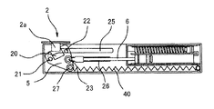
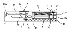
- FIG. 14 (a) to 14 (c) show a buffer closing device disclosed in Patent Document 1.
- FIG. Symbol F is a duck that constitutes a main body frame that is a fixed body.
- the Kamoi F has a lateral groove.
- the sliding door D which is a moving body, has a door neck D1 that fits in the lateral groove.
- the retractor (device main body) 1 is provided in the sliding door D, and the striker (engagement member) 2 is attached to the lateral groove of the Kamoi F.
- the striker 2 is attached in the lateral groove of the Kamoi F and protrudes the engaging protrusion 2a downward.
- the retractor 1 is slidable when the case 3 is placed in the case 3 and the standby posture (see FIG.
- a latch (engaging member) 5 that can be switched to a retracted posture (see FIG. 14C), and a coil spring 40 as the closing means B.
- Reference numeral 12 denotes a first cylinder which drives the first piston 11.
- Reference numeral 6 denotes a piston rod that pivotally supports the latch 5.
- the case 3 has a concave groove 3a whose upper side opens from one end to the middle, and a first guide groove 25 and a second guide groove 26 extending in the front-rear direction.
- the concave groove 3a allows the engaging protrusion 2a to enter and exit the case.
- the guide grooves 25 and 26 guide the sliding of the latch 5.
- the guide groove 25 has a bent portion 25a that is bent downward at one end side of the case and locks the latch 5 in a non-slidable manner.
- the case 3 forms a part of the nose which continues with the nose D1 in the attachment state which embed
- the latch 5 is slid by the urging force accumulated in the coil spring 40 and automatically switches the sliding door D to the closed position. Further, when the latch 5 is slid to the right side of the drawing by opening the sliding door D from the closed position, an urging force is accumulated accordingly, as shown in FIG. When the sliding door is further moved in the opening direction, it is switched to the standby posture again.
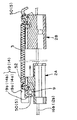
- FIG. 15 (a) and 15 (b) show a movement assist device (sliding assist mechanism) disclosed in Patent Document 2.
- the main body frame which is a fixed body displaces the sliding door which is a moving body, and the sliding door projects a striker (projection body) 9 on the upper end surface.
- the retracting tool (retracting unit) includes a case 1 attached to the main body frame, sliders 2A and 2B slidably disposed in the case 1, and a latch 5 pivotally supported via a shaft 8 with respect to each slider. It consists of biasing means 3.
- the sliders 2A and 2B have convex portions 22 on the upper and lower surfaces, and the respective convex portions 22 are fitted into guide grooves 12b and 16b provided on the upper and lower surfaces of the case 1, and are guided by the upper and lower guide means. It is slid while being done.
- Each latch 5 has projections 52 on the upper and lower surfaces, and each projection 52 is fitted in guide grooves 14 and 19 provided on the upper and lower surfaces of the case 1 and is slid while being guided by the upper and lower guide means.
- the guide grooves 14 and 19 include linear grooves 14a and 19a parallel to the guide grooves 12b and 16b, and substantially L-shaped locking grooves 14b and 19b provided on both sides of the linear grooves 14a and 19a.
- the latches 5 on both sides in FIG. 15A and the right latch 5 in FIG. 15B are in the standby posture.
- the upper and lower protrusions 52 are locked in the corresponding locking grooves 14b and 19b, and the position of the latch 5 is regulated while receiving the biasing force accumulated in the biasing means 3 together with the slider 2A.
- the striker 9 hits the inner surface of the corresponding hook portion 50 of the latch 5, and the latch 5 And is switched from the standby posture to the retracted posture as shown on the left side of FIG.
- the striker having a relatively simple structure is disposed in the lateral groove of the main body frame, which requires a more complicated structure and a larger installation space.
- the retractor which becomes is arrange
- a part of the nose protruding from the end face of the sliding door must be excised to form a concave part for installation after excision. was not easy.
- the retractable tool is restricted to a width of about 20 mm, a high positional accuracy is required for the latch that engages with and disengages from the striker, and a part of the upper surface of the case is opened. The problem was that dust or dust that could cause malfunctions was easily stored in the case.
- the buffer closing device disclosed in Patent Document 2 instead of the structure of FIG. 15 (a), it is configured by left and right one side, that is, a pair of latches and sliders and biasing means, or a single latch and slider and biasing force. Since it can be configured by means, it can also be applied to sliding doors that are opened and closed along the lateral grooves of the main body frame.
- the retractor is disposed on the main body frame, and the striker is disposed on the sliding door.
- a lateral groove-shaped opening for allowing the striker to enter and exit the case is formed on the lower surface of the case.
- the object of the present invention is to make it easier to relax or maintain the accuracy of the position of the latch and striker of the retractor as a movement assisting device for the moving body, thereby improving versatility and operating characteristics. It is to improve.
- the present invention provides a movement assisting device having any of the following features (1) to (3).
- a retracting tool having a case and a latch that is slidably locked in the case and a retractable posture that can be slid by releasing the locking, and a retracting tool that has a biasing means, and the latch in the standby posture
- a striker that switches from a retracted posture to a standby posture, and either the retractor or the striker is provided on a fixed body and a movable body that is movably disposed on the fixed body
- the movement assisting device in which the other of the retractor and the striker is provided on the other of the fixed body and the movable body, and the movable body is movable by a biasing force when the latch is switched from a standby posture to a retracted posture
- the case has an invitation portion for a striker that is cut out so as to be narrow from one end in the longitudinal direction to the middle of the other end, and Mobility aid
- the moving body includes sliding doors and drawers such as a shoji and a shoji.
- the fixed body is a rectangular main body frame that supports a movable body (such as a sliding door or a drawer) in a movable manner.
- a movable body such as a sliding door or a drawer
- the fixed body is composed of a horizontal bar or sill on the lower side of the sliding door, a horizontal bar or a duck on the upper side of the sliding door, and a vertical tree that supports the sill and the duck from both sides.
- An opening having a size corresponding to opening and closing is defined.
- the fixed body is a housing such as a cabinet that divides a storage space corresponding to the moving body.
- the configuration in which the movement assist device of the present invention is attached to the fixed rail the configuration in which the movement assist device of the present invention is attached to the fixed rail.
- middle rail of a drawer or a guide rail, or a movable rail can be considered.
- the striker switches the latch of the retracting tool between the retracted posture and the standby posture. In the standby posture, the latch is locked so as not to slide against the urging force accumulated in the urging means.
- the latch In the retracted position, for example, the latch is unlocked in a state in which the engagement protrusion is constrained, and the moving body is moved from the middle position to the closed position or from the middle position by the biasing force accumulated in the biasing means. Move to open position.
- the present invention having the above characteristics further preferably has one or both of the following (2) and (3). That is, in the movement assistance device of the present invention, (2)
- the case has an installation surface arranged at a corresponding attachment portion of the fixed body or the movable body, and the invitation portion is formed at a portion excluding the installation surface.
- the case further includes a guide portion that is narrowly provided at one end side and is inclined toward the invitation portion.
- the movement assisting device of the present invention has a guide portion that is notched in the width direction of the case so that the case of the retracting tool becomes narrow from one end in the longitudinal direction to the middle of the other end. Since the part of the latch is exposed to the outside from the inside of the case at the invitation part, and when the striker is moved along the invitation part of the case, the striker is engaged with and disengaged from the latch outside the case. Compared to the movement assist device in which the striker is engaged with and disengaged from the latch in the case, the relative accuracy between the striker and the case side latch is relaxed, and there is a risk of the striker buffering due to deformation of the moving body. It can be eliminated and the operating characteristics can be improved.
- the movement assistance apparatus does not have an opening on the upper end surface of the case, so that dust or dust is difficult to accumulate in the case.
- the movement assist device of the present invention does not require an opening or groove for entering and exiting the striker, so that even if the retractor is reduced in size and weight, The rigidity can be maintained.
- the movement assisting device of the present invention has the feature (2) above, so that the striker's invitation is provided at a portion excluding the installation surface where the case of the retracting device is disposed at the corresponding attachment portion of the fixed body or the moving body. Since the portion is formed, it can be carried out without impairing the stable attachment property of the retractor as inferred from each form.
- the movement assisting device of the present invention has the above feature (3), one end side of the case is narrowly provided and has a guide portion inclined toward the invitation portion. Can be satisfactorily transferred to the invitation portion by the guide action of the guide portion, and the operating characteristics can be further improved.
- (A) is a side view of the duck (yoko) of a main-body frame
- (B) is the bottom view which looked at the duck (yoko) from the lower side.
- (C) is an end view of Kamoi (Yokogi). It is a perspective view which shows the retractor which comprises the movement assistance apparatus which concerns on 1st Embodiment of this invention with a single item.
- FIG. 1 It is a figure which shows the relationship between the sliding door of 1st Embodiment, and a striker
- (A) is a top view of a sliding door
- (B) is a figure which shows the upper end part vicinity of the side surface of a sliding door
- (C) is an end elevation of a sliding door. It is.
- FIGS. 1 (a) to 9 (c) show a first embodiment of the present invention
- FIGS. 10 (a) to 13 (b) show a second embodiment of the present invention.
- the main part of the first embodiment, its retractor, sliding door and striker, receiving member, light shielding member, operation, changes in the second embodiment, and operation will be described in detail in this order.
- a part of the configuration is simplified or omitted due to restrictions on drawing.
- the movement assist device includes a retracting tool 5 and a striker 6, and a sliding door 50 that is an example of a moving body is positioned between an open position and a closed position of a main body frame 9 that is an example of a fixed body.
- the sliding door 50 with a nose that fits into the lateral groove 9a of the main body frame 9 is targeted.
- the moving body and the fixed body may be replaced by, for example, the drawer and the main body frame instead of the sliding door 50 and the main body frame 9 in this example, and in this case, the drawing position of the main body frame that is the fixed body may be used.
- the drawer may be movable between the storage position and the storage position. As shown in FIGS.
- the retractable tool 5 is attached to the main body frame 9 in a lateral groove 9 a provided in the Kamoi (Yokogi) 90.
- a frame member 92 having a U-shaped cross section is attached to the lateral groove 9a. Yes.
- the frame member 92 is not an essential component in the embodiment of the present invention, and can be omitted as necessary.
- FIGS. 1 (a) and 1 (b) a frame member 92 having a U-shaped cross section (that is, substantially equal to the shape with one side of the rectangle removed) is attached to the lateral groove 9a.
- the frame member 92 is not an essential component in the embodiment of the present invention, and can be omitted as necessary.
- the upper end surface 51 of the sliding door 50 is a substantially rectangular flat surface, and the striker 6, the light shielding member 7, and the receiving member 8 are arranged in parallel on a substantially straight line.
- the shape of the striker 6 and the receiving member 8 form a nose of a predetermined length.
- the door neck formed by the striker 6 and the receiving member 8 has a dimension that fits into the groove of the lateral groove 9a of the main body frame, and the groove width is normally set to about 15 to 20 mm.
- the main body frame 9 divides a rectangular opening that is opened or closed by the sliding door 50 by, for example, an upper duck 90 and a lower sill (crossbar) and vertical bars 91 on both sides.
- a pair of lateral grooves 9a corresponding to the door nose are formed in the Kamoi 90 in parallel.
- the sliding door 50 corresponds to the horizontal groove 9a of the head 90, and a predetermined length is provided by the standing walls 63 and 64 and the receiving member 8 that constitute the nose forming portion of the striker 6 on the upper end surface 51 of the sliding door 50. This is an example of forming a nose.
- the retracting tool 5 includes a case 1 disposed in the lateral groove 9a, a slider 2 slidably disposed in the case 1, and a pivotally supported by the slider 2 to be engaged with a corresponding portion of the case 1 (non-slidable).
- a latch 3 that can be switched to a standby posture that is unlocked and a retracted posture that is unlocked and slidable, an urging means S, and a braking means 4.
- the latch 3 when the latch 3 is switched from the standby position to the retracted position, the sliding door 9 is pulled from the open position to the closed position by the biasing force accumulated in the biasing means S, for example.
- the case 1 is an elongated resin injection-molded body having a width that can be attached to the lateral groove 9a. It has the invitation part 1a notched inside the width direction (direction orthogonal to a longitudinal direction) of case 1 so that it may become thin from one end to the middle of the other end, and also toward the invitation part 1a from one end side And has an inclined guide portion 1b. And the internal space of this case 1 is so that the lower surface 10 used as the installation surface with the horizontal groove 9a at the time of attaching the retractor 5 to the horizontal groove 9a of the Kamoi 90, the both side surfaces 12, and the opening of the upper side of the case 1 may be blocked. It is partitioned from the outside by a cover 15 attached to the case 1.
- an urging means arrangement portion 11a and a braking means arrangement portion 11b formed in two rows on both sides along the longitudinal direction, and mounting holes 13a and 13b formed through both ends in the longitudinal direction are formed.
- the control part 12d which is provided in the arrangement
- the guide portion 14 is located between the placement portion 11a and the placement portion 11b, and extends from a substantially intermediate position toward the front of the mounting hole 13a.
- the guide portion 14 is approximately L from the straight groove 14a toward the mounting hole 13a.
- the locking groove 14b is bent into a shape.
- the cover 15 has a biasing means placement portion and a braking means placement portion (not shown) corresponding to the case 1, and one side of the cover 15 is notched in the longitudinal direction so that the engagement protrusion 61 of the striker 6 is located in the center in the width direction of the cover 15
- a restriction portion (not shown) provided on the end portion opposite to the mounting portion 17 and pressing the end portion of the cylinder 50 as the braking means S from above, and a guide portion (not shown) corresponding to the guide portion 14 are provided. ing.
- the guide portion (not shown) has a linear groove corresponding to the linear groove 14a and a substantially L-shaped locking groove corresponding to the locking portion 14b.
- symbol 18 is a recessed part provided in order to form the said guide piece.
- a plurality of pairs of engaging portions 12 a and engaging portions 19 a that are engaged with each other when the cover 15 is overlapped with the case 1 are provided on both side surfaces 12 of the case 1 and both side surfaces 19 of the cover.
- the latch 3 is connected to the invitation portion 16 (retracted) of the cover 15. It arrange
- FIG. The case 1 and the cover 15 described above have the same height and width as the doors provided in the conventional sliding doors except for the portions where the invitation portions 16 are formed. It is designed as follows.
- the outer shape of the case 1 defines the door nose forming part that replaces the conventional door nose, on both side surfaces 12 and 19 excluding the invitation part 1a and the guide part 1b and the outer surface of the cover 15, and will be described later. This enables usage as in the second embodiment.
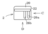
- the slider 2 is in the form of a small resin block disposed in the space between the case 1 and the cover 15, and includes upper and lower surfaces 20, The convex parts 23 and 24 and the through-holes 26a and 26b provided in 21, the insertion hole 25 provided in the back surface 22 and communicating with the through-holes 26a and 26b, and the connection for lowering from the upper surface 20 side And a shaft portion 27.
- the upper surface 20 is disposed on the cover 15 side and the convex portion 23 is fitted with the guide portion on the cover 15 side
- the lower surface 21 is disposed on the case 1 side and the convex portion 24 is disposed on the guide portion 14.
- a retaining ring 52 of FIG. 3 is disposed in the through hole 26b.
- Brake means 4 is a piston type damper.
- This piston-type damper may be any known one (for example, one disclosed in Japanese Patent Application Publication No. 2006-29564), and the cylinder 40 and the piston rod 41 that gently moves in and out of the cylinder 40 are provided.
- the piston rod 41 may be configured to be gently driven with respect to the fixed cylinder 40.
- the cylinder 40 has a neck-shaped locking groove 42 on the outer periphery of the rear end
- the piston rod 41 has a neck-shaped locking groove 43 on the outer periphery of the tip.
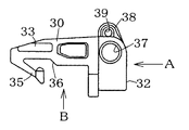
- the latch 3 is a resin molded body having a thickness substantially the same as that of the slider 2, and is provided with projections 33, provided on the upper and lower surfaces 30, 31. 34, a pivotal support hole 37 provided in the vicinity of the back surface 32 and penetrating in the vertical direction, a claw portion 35 provided on the opposite side of the back surface 32, that is, on the front side, and a restraining portion lacking the inside of the claw portion 35 36 and a spring locking portion 38 projecting from the back 32 side to one side.
- projections 33 provided on the upper and lower surfaces 30, 31. 34
- a pivotal support hole 37 provided in the vicinity of the back surface 32 and penetrating in the vertical direction
- a claw portion 35 provided on the opposite side of the back surface 32, that is, on the front side
- a restraining portion lacking the inside of the claw portion 35 36 and a spring locking portion 38 projecting from the back 32 side to one side.
- the upper surface 30 is disposed on the cover 15 side, and the convex portion 33 is fitted with the guide portion on the cover 15 side, and the lower surface 31 is disposed on the case 1 side, and the convex portion 34 is disposed on the guide portion 14. Mates with.
- the shaft portion 27 is fitted into the pivot hole 37.
- the locking portion 38 has a latching hole 39, and the other end S2 of the biasing means S is locked there.
- a coil spring is used in the present embodiment.
- the entire size of the coil spring is substantially equal to the length of the cylinder 40 in a state where the elastic force accumulated to the extent that the coil spring has no urging force is released.
- the urging force can be accumulated by being extended through the piston rod 41 for a long time.
- mounting locking portions S1 and S2 are provided.
- Each of the above members is, for example, together with the piston type damper that is the braking means 4 and the coil spring that is the biasing means S in a state where the slider 2 and the latch 3 are connected via the engagement of the shaft portion 27 and the pivotal support hole 37.
- the retraction tool 5 is completed by being incorporated in the case 1 and attaching the cover 15 to the case 1.
- the retaining ring 52 is engaged with the engaging groove 43 on the outer periphery of the rod end in the through hole 26b.
- the braking means 5, the slider 2 and the latch 3 are arranged along the arrangement portion 11 b of the case 1.
- the cylinder 40 is fixed to the case 1 by engaging the engaging groove 42 with the restricting portion 12d (and a cover-side restricting portion (not shown)).
- the lower convex portion 24 and the convex portion 34 are fitted to the guide portion 14 of the case 1 (and the upper convex portion 23 and the convex portion 33 are fitted to a cover side guide portion (not shown).
- the case 1 is slidably disposed.
- the coil spring which is the urging means S has a latching portion S1 on one end side latched on the latching portion 12c of the case 1 and a latching portion S2 on the other end side in the latching hole 39 of the latch side latching portion 38. Locked.
- the latch 3 is engaged so that the protrusions 33 and 34 slide along the linear groove 14a as the slider 2 slides, and the latch 3 enters the locking groove 14b from the linear groove 14a and cannot slide. It is switched to the standby posture to be stopped.
- the other end locking portion S2 of the coil spring which is the biasing means S is locked to the latch 3, but instead the other end locking portion S2 may be locked to the slider 2 side. .
- the above retractor 5 is arranged so that the lower surface 10 as the installation surface thereof is seated on the inner bottom surface of the horizontal groove 9 a of the Kamoi 90 with respect to the horizontal groove 9 a.
- the fixing operation is performed by the screw M inserted into the hole 17a and the mounting hole 13a and the screw M inserted into the mounting hole 13b.
- one side surface 19 on which the guiding portion 1a (16) of the both side surfaces 12 of the case 1 and the side surface 19 of the cover 15 is formed is pressed against one inner side surface of the lateral groove 9a without a gap.
- the other side surface 19 is set so as to maintain a slight gap between the other side surface 19 and the other inner side surface of the lateral groove 9a.
- This gap has a dimension that allows the standing wall 63 that constitutes the nose forming portion of the striker 6 to be described later to escape.
- the sliding door 50 is in a state without a nose, that is, in this example, the upper end surface 51 is formed as a flat surface.
- the end surface 51 On the end surface 51, a part of the striker 6 disposed between the left and right ends 50 a, 50 b of the sliding door 50 and the receiving member 8 form a nose and is disposed between the striker 6 and the receiving member 8.
- a light shielding member 7 is provided.
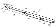
- the striker 6 is a resin injection-molded body, and as shown in FIG. 6, an elongated attachment portion 60, and an engagement protrusion 61 that is provided at one side edge at a substantially intermediate position of the attachment portion 60.
- a standing wall 63 erected in a substantially L shape along one side edge of the mounting portion 60, and a substantially L shape in the other side edge of the mounting portion 60 along the one end side with the engaging protrusion 61.
- the standing wall 64 and a substantially rectangular solid receiving portion 66 provided at one end are integrally formed.
- the mounting portion 60 has the same width as the door fitting fitted in the lateral groove 9a, and is provided at the end opposite to the elongated mounting hole 62a, the circular mounting hole 62b, and the receiving portion 66. And a mounting hole 62c. As shown in FIGS. 2A and 2B, a gap absorbing spacer 69 is attached to the mounting hole 62c as necessary.
- the engagement protrusion 61 is engaged with and disengaged from the latch 3 of the retractor 5.
- the standing walls 63 and 64 and the receiving portion 66 are set in the nose forming portion of the sliding door 50.
- the receiving portion 66 is partitioned by both side surfaces 66, upper and lower surfaces, and an end surface 67, and as shown in FIGS. 2 (a) and 2 (b), the light shielding member 7 is located above the receiving member 8. It takes charge of the means for attaching to the end surface 51 and the nose forming action of the sliding door 50.
- the receiving portion 66 is provided with a mounting hole 68 in the center portion and a substantially inverted T-shaped fitting groove 65 in the end surface 67.
- the fitting groove 65 includes a lower horizontal groove 65 a (not shown in the drawing) and a vertical groove 65 b, and has a groove shape capable of fitting the corresponding end portion 74 of the light shielding member 7. ing. That is, of the corresponding end portions 74 of the light shielding member 7, the end portion 70a of the horizontal portion 70 is fitted into the horizontal groove, and the end portion 71a of the light shielding portion 71 is fitted into the vertical groove 65b.
- the above striker 6 is attached to the upper end surface 51 of the sliding door 50 by the three screws M inserted through the attachment holes 62 a and 62 b and the attachment hole 68.
- the attachment holes 62a and 68 have a long hole shape, and are finely adjustable in the width direction when the striker 6 is attached straight to the upper end surface 51.
- the receiving member 8 includes means for attaching the light shielding member 7 to the upper end surface 51 of the sliding door 50, as shown in FIGS. 2 (a) and 2 (b) and FIGS. 7 (a) and 7 (b).
- the receiving portion 66 is the same as the receiving portion 66 in that it takes charge of the operation of forming the nose. That is, the receiving member 8 is made of a resin molded body roughly divided by both side surfaces 81, upper and lower surfaces 82 and 83, and front and rear end surfaces 84 and 88.
- the receiving member 8 has two mounting holes 80 penetrating the upper and lower surfaces 82, 83, a substantially inverted T-shaped fitting groove 85 carved in the front end surface 84, and a rear end surface 88 projecting from the rear end surface 88.
- a locking vertical wall 87 located on a seat 86 extending from the lower side of the end face 88 is provided.
- the rear wall 87 is a place used when the receiving member 8 is used for a sliding sliding door, and may be omitted in the case of a sliding door other than a drawing door.
- each mounting hole 80 formed in the receiving member 8 has a long hole shape that is long in the width direction.
- the fitting groove 85 includes a vertical groove 85b and a lower horizontal groove 85a, and has a groove shape in which a corresponding end of the light shielding member 7 can be fitted. That is, of the corresponding end portions of the light shielding member 7, the end portion 70a of the horizontal portion 70 is fitted into the horizontal groove 85a, and the end portion 71a of the light shielding portion 71 is fitted into the vertical groove 85b.
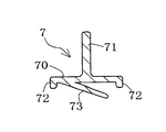
- the light shielding member 7 has a sliding door 50 without a nose, that is, in this example, the upper end surface 51 is formed as a flat surface, and the nose is formed by the striker 6 and the receiving member 8 there. It is a member that shields light so that it does not leak out from a place where there is no neck. That is, the light shielding member 7 is made of an elastic material such as resin or rubber, has a substantially inverted T-shaped longitudinal section, and projects a horizontal portion 70 and a light shielding portion that is perpendicular to the horizontal portion 70 (vertically upward).
- the light shielding member 7 is substantially the same in height as the receiving portion 66 and the receiving member 8 of the striker 6 and attached to the upper end surface 51 of the sliding door 50, and the width is larger than the width of the case 1. It is set small.
- the light shielding member 7 described above is attached to the upper end surface 51 of the sliding door 50 in a state where both sides are engaged with the receiving portion 66 and the receiving member 8 of the striker 6 fixed to the upper end surface 51.
- the light shielding member 7 has the elastic contact portion 73 in pressure contact with the upper end surface 51, and the light shielding portion 71 prevents light leakage through the lateral groove 9 a when the sliding door 50 is in use.
- the attachment method to the sliding door 50 of the light shielding member 7 may be bonded to the corresponding end surface of the sliding door 50 with an adhesive, a double-sided adhesive tape, or the like, instead of the method of engaging with the sliding door 50, You may press-fit in the attachment site
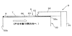
- FIGS. 8A to 8C show a process in which the sliding door 50 is moved from the open position to the close direction.
- the latch 3 constituting the retractor 5 is in the standby posture.
- the coil spring as the urging means S is extended to accumulate the urging force.
- the protrusions 33 and 34 are locked in the case side locking groove 14 b and the cover side locking groove, thereby restricting the position of the slider 2 against the biasing force of the biasing means S.
- the engaging protrusion 61 hits the corresponding portion of the latch 3 when the sliding door 50 is further moved in the closing direction.
- the latch 3 is rotated counterclockwise with the shaft portion 27 as a fulcrum due to the stress, and the protrusions 33 and 34 are unlocked from the locking groove 14b by the rotation, and are engaged with the linear groove 14a to the retracted posture. Can be switched.
- the engaging protrusion 61 is restrained by the inside of the latch side claw portion 35, that is, by the restraining portion 36.
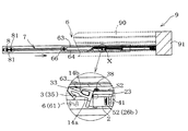
- FIGS. 9A to 9C show a state where the sliding door 50 is moved to the closed position by the urging force of the urging means S after the latch 3 is switched to the retracted position. That is, in this movement assisting device, as shown in the enlarged view of FIG. 9B, when the latch 3 is switched to the retracted posture, the engaging protrusion 61 is restrained by the latch side restraining portion 36. In this restrained state, the sliding door 50 is moved to the closed position in conjunction with the slider 2 being slid by the urging force of the urging means S together with the latch 3. In this case, in this embodiment, when the sliding door 50 is moved by the urging force of the urging means S, it is slid gently by being braked by the braking means 4 described above.
- the light shielding portion 71 of the light shielding member 7 can prevent indoor light from leaking from the upper end surface 51 of the sliding door 50 to the outside when the sliding door 50 is in the closed position.
- the latch 3 is moved together with the slider 2 to the left via the engaging protrusion 61 engaged with the restraining portion 36 in the retracted position. By this movement, the urging force is accumulated in the urging means S.
- the convex portions 33 and 34 reach the locking groove 14b from the linear groove 14a.
- the latch 3 rotates in the clockwise direction about the shaft portion 27 as a fulcrum by the reaction force when the engaging projection 61 pushes the claw portion 35 and comes out of the restricting portion 36, while the convex portions 33 and 34 enter the locking groove 14 b.
- the urging force stored in the urging means S is maintained as long as the latch 3 is in the standby posture.
- the movement assist device according to the present embodiment is manufactured in a state where the end surface 51 on the nose side is a flat surface as the sliding door 50, compared to a conventional sliding door with a nose, and the flat surface. Since the striker 6 and the receiving member 8 can be attached to the door to form the door nose, the man-hours required for the production of the sliding door 50 can be reduced, and the movement assist device can be easily adopted. Further, since the light shielding member 7 is disposed between the above-described door nose forming portions 63 and 64 and the receiving member 8, it is possible to prevent indoor light from leaking outside.
- or FIG.13 (b) has shown the sliding door auxiliary
- the same members as those in the first embodiment and the same functional parts are denoted by the same reference numerals, the description thereof is omitted as much as possible, and the changed configuration will be described. That is, the sliding door assisting device of the second embodiment is the same as the movement assisting device of the first embodiment in the configuration of the retracting tool 5, the shielding member 7, and the receiving member 8.
- the difference between the configuration of the striker 6A and the configuration of the striker 6A in the lateral groove 9a on the main body frame side is different.
- 10 (a) to 10 (c) are on the flat upper end surface 51 of the sliding door 50, and between the left and right ends 50a, 50b of the sliding door 50, the case 1 of the retractor 5 and the light shielding member.
- 7 shows an arrangement example in which the receiving members 8 are arranged on a substantially straight line.
- the retractor 5 is attached by two screws M inserted through the holes 17a and the attachment holes 13b, and the light shielding member 7 is fitted or received between the corresponding end side of the case 1 and the receiving member 8, respectively.
- Engagement structure that is, fitting or engagement between one end 74 of the light shielding member 7 and the fitting groove 13c of the case 1 (see the enlarged view on the right side of FIG. 13A), the other end 74 of the light shielding member 7. Are connected to each other through fitting or engagement with the fitting groove 85 of the receiving member 8.
- 2nd Embodiment is the sliding door 50 with a nose like said 1st Embodiment, according to the external shape of the case 1 which comprises the retracting tool 5, or outside of the case 1 Since the door neck is formed by the shape and the outer shape of the receiving member 8, the manufacturing cost of the sliding door 50 can be reduced, and the retracting tool 5 is incorporated into the sliding door 50 by special processing as in the cited reference 1.
- the light shielding member 7 can be connected and fixed between the case 1 and the single receiving member 8 without a gap.
- the striker 6 of the second embodiment is an injection molding in which an attachment portion 60 and an engagement protrusion 61 projecting from the attachment portion 60 are integrally formed. Is the body.
- the mounting portion 60 has a width dimension that fits in the lateral groove 9a, and includes a guide plate portion 63 that is bent at a right angle on one side, and two mounting holes 62a and 62b.
- the striker 6 described above is attached to the lateral groove 9a by two screws M inserted through the attachment holes 62a and 62b after the attachment portion 60 is positioned on the bottom surface in the groove.
- the mounting hole 62a is not circular but has a long hole shape in which the width direction is increased, so that the striker 6 can be finely adjusted in the width direction when the striker 6 is mounted straight to the lateral groove 9a.
- the engaging projection 61 protrudes into the lateral groove in the mounted state.
- the guide plate portion 63 is opposed to the engaging protrusion 61 with a predetermined interval (same or slightly larger than the width dimension of the portion of the retractor 1 where the invitation portion 1a is provided).
- FIG. 13A and FIG. 13B show the retracting operation of the sliding door assist device of the second embodiment, that is, the retracting tool 5 and the striker 6A.
- FIG. 13A assumes a process of moving the sliding door 50 in the direction indicated by the arrow in FIG.
- the standby posture of the latch 3 constituting the retractor 5 is shown together with the striker 6.
- the coil spring as the urging means S is stretched to accumulate the urging force.
- the convex portions 33 and 34 are locked in the case side locking groove 14b and a cover side locking groove (not shown), thereby restricting the position of the slider 2 against the biasing force of the biasing means S. Yes.
- the engaging protrusion 61 of the striker 6 whose position is fixed is located on one end side of the retracting tool 5.
- the guide part 1b provided is relatively moved along the invitation part 1a (16) and comes into contact with the corresponding part of the latch 3 exposed from the inside of the case 1 to the outside.
- the latch 3 is rotated counterclockwise with the shaft portion 27 as a fulcrum by the stress received from the engagement protrusion 61, and the protrusions 33 and 34 are unlocked from the corresponding locking grooves 14b by the rotation, thereby corresponding. It is switched to the retracted posture by fitting with the straight groove 14a.
- the engaging protrusion 61 is restrained by the inside of the latch side claw portion 35, that is, by the restraining portion 36.
- FIG. 13B shows a state where the sliding door 50 is moved by the biasing force of the biasing means S and switched to the closed position after the latch 3 is switched to the retracted posture. That is, in this sliding door assisting device, when the latch 3 is switched to the retracted position as shown in the figure, the slider 2 and the latch 3 are attached to the biasing means S in a state where the engaging protrusion 61 is restrained by the latch side restraining portion 36. The sliding door 50 is moved to the closed position as it is slid by the force. In this case, in this embodiment, when the sliding door 50 is moved by the urging force of the urging means S, the sliding door 50 is gently moved under the braking of the braking means 4 described above. In the closed position of the sliding door 50, since it has the light-shielding member 7 connected without gap between the drawing-in tool 5 and the receiving member 8A, it can prevent that indoor light leaks outside, for example.
- the latch 3 is rotated clockwise with the shaft portion 27 as a fulcrum by the reaction force when the engaging protrusion 61 pushes the claw portion 35 out of the restraining portion 36, and the convex portions 33, 34 correspond to the corresponding locking grooves. 14b is engaged and switched to the standby posture.
- the urging force stored in the urging means S is maintained as long as the latch 3 is in the standby posture.
- the sliding door 50 is produced in a state in which the end surface 51 on the side of the nose is flattened as compared with a conventional sliding door with a nose. Since the door 5 can be formed on the sliding door 50 by attaching the retracting tool 5 and the receiving member 8 to the surface, the man-hours necessary for manufacturing the sliding door 50 can be reduced. Furthermore, since the said movement assistance apparatus is provided with the light-shielding member 7 between the case 1 and the receiving member 8 of the drawing-in tool 5, it can prevent that indoor light leaks outside.
- latch 30 ... upper surface 31 ... lower surface 32 ... back surface 33, 34 ... convex part 35 ... claw part 36 ... restraint part 37 ... pivot hole 38 ... Locking part 39 ... Hooking hole 4 ... Braking means 40 ... Cylinder 41 ... Piston rod 42, 43 ... Neck-like locking groove 5 ... Retracting tool 50 ... Sliding door (corresponding to a moving body) 50a, 50b ... end face 51 ... upper end face 6, 6A ... striker 60 ... mounting portion 61 ... engaging projection 62a, 62b, 62c ... mounting hole 63, 64 ... standing wall 65 ... fitting groove 66 ... receiving portion 67 ... end surface 68 ... Mounting hole 69 ...
- Space absorbing spacer 7 Light shielding member 70 ... Horizontal part 71 ... Light shielding part 71a ... End part 72 ... Leg part 73 ... Elastic contact part 8 ... Receiving member 80 ... Mounting hole 81 ... Side surface 82 ... Upper surface 83 ... Bottom surface 84 ... Front end surface 85 ... Fitting groove 85a ... Horizontal groove 85b ... Vertical groove 86 ... Seat portion 87 ... Locking vertical wall 88 ... Rear end surface 9 ... Main body frame (corresponding to a fixed body) 9a ... Yokomizo 90 ... Kamoi (Yokogi) 91 ... Vertical tree 92 ... Frame member S ... Biasing means S1 ... Kamoi (Yokogi) S2 ... Locking parts on both sides)
Landscapes
- Engineering & Computer Science (AREA)
- Mechanical Engineering (AREA)
- Lock And Its Accessories (AREA)
- Power-Operated Mechanisms For Wings (AREA)
- Wing Frames And Configurations (AREA)
Abstract
Description
(1)
ケースと前記ケース内に摺動不能に係止した待機姿勢と前記係止を解除して摺動可能となる引込姿勢とに切り換えられるラッチ並びに付勢手段を有する引込具と、前記ラッチを待機姿勢から引込姿勢に切り換えたり引込姿勢から待機姿勢に切り換えるストライカーとを備え、前記引込具及び前記ストライカーのいずれか一方を、固定体及び前記固定体に移動可能に配置された移動体にそれぞれ設けるとともに、前記引込具及び前記ストライカーの他方を、前記固定体及び前記移動体の他方に設け、前記ラッチが待機姿勢から引込姿勢に切り換えられると前記移動体が付勢力により移動可能となる移動補助装置において、前記ケースは、長手方向の一端から他端の途中までを幅細となるよう切り欠かれたストライカー用の誘い部を有し、かつ、前記ラッチの一部をケース内から前記誘い部に露出配置していることを特徴とする移動補助装置。
(2)
前記ケースは、前記固定体又は前記移動体の対応取付部に配置される設置面を有し、前記誘い部が前記設置面を除いた部分に形成されている。
(3)
前記ケースは、一端側が幅細に設けられているとともに、前記誘い部に向けて傾斜した案内部をさらに有している。
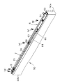
第1実施形態の移動補助装置は、引込具5及びストライカー6から構成され、移動体の一例である引戸50を、固定体の一例である本体枠9と、の開位置と閉位置との間で移動する構成のうち、特に本体枠9の横溝9aに嵌合する戸首付きの引戸50を対象としている。なお、移動体と固定体は、本例の引戸50と本体枠9に替えて、例えば引出を移動体とし、本体枠を固定体としてもよく、この場合、固定体である本体枠の引出位置と収納位置との間で引出を移動可能とする構成としてもよい。そして、本体枠9には、図1(a)及び図1(b)に示すように、鴨居(横木)90に設けられている横溝9a内に引込具5が取り付けられている。なお、横溝9aには図1(a)及び図1(b)に示すように、断面がコの字形の(すなわち、長方形の一辺が取り除かれた形状と略等しい)枠部材92が装着されている。この枠部材92は、後述の第2実施形態に示すように、本発明の実施形態において必須の構成ではなく、必要に応じて省略可能である。引戸50の上端面51は、図2(a)及び図2(b)に示すように、略矩形の平坦面であり、ストライカー6、遮光部材7、および受け部材8が略直線上に並設されており、ストライカー6の形状及び受け部材8によって所定長さの戸首を形成している。
引込具5は、上記横溝9aに配設されるケース1と、ケース1に摺動自在に配されたスライダー2と、スライダー2に枢支されてケース1における対応部に係止(摺動不能に係止)する待機姿勢と係止が解除されて摺動可能となる引込姿勢とに切り換えられるラッチ3と、付勢手段Sと、制動手段4とを有する。そして、本実施形態では、ラッチ3が待機姿勢から引込姿勢に切り換えられると、付勢手段Sに蓄積されている付勢力により引戸9が例えば開位置から閉位置へ引き込まれる。
第1実施形態では、図2(a)及び図2(b)に示すように、引戸50が戸首なしの状態、つまりこの例だと上端面51が平坦面に形成されており、その上端面51にあって、引戸50の左右端50a,50bの間に配置されたストライカー6の一部及び受け部材8により戸首を形成するとともに、ストライカー6と受け部材8との間に配置された遮光部材7を有している。
受け部材8は、図2(a)及び図2(b)並びに図7(a)及び図7(b)に示すように、遮光部材7を引戸50の上端面51に取り付けるための手段と、戸首形成作用とを受け持つ点で上記受け部66と同じである。すなわち、受け部材8は、両側面81及び上下面82,83並びに前後端面84,88で概略区画された樹脂成形体からなる。受け部材8には、上下面82,83を貫通している2つの取付孔80と、前端面84に刻設された略逆T形の嵌合溝85と、後端面88に突出されて後端面88の下側から延びた座部86上に位置している係止用縦壁87とが設けられている。なお、後壁87は、受け部材8が引分用引戸に用いられる際に使用される箇所であり、引分用以外の引戸の場合は省略してもよい。受け部材8に形成された各取付孔80は、図2(a)及び図2(b)に示すように、幅方向に長い長孔形状となっており、受け部材8をねじMを用いて引戸50の上端面51おけるストライカー6の延長線上に取り付けるときに、その取付位置を上端面51の幅方向において微調整することができる。嵌合溝85は、縦溝85b及び下側の水平溝85aからなり、遮光部材7の対応端部を嵌合可能な溝形状となっている。すなわち、遮光部材7の対応端部のうち、水平部70の端部70aは水平溝85aに嵌合され、遮光部71の端部71aは縦溝85bに嵌合される。
この遮光部材7は、引戸50が戸首なしの状態、つまりこの例だと上端面51が平坦面に形成され、そこにストライカー6及び受け部材8により戸首を形成したため、室内の光が戸首の無い箇所から外へ漏れないように遮光する部材である。すなわち、遮光部材7は、樹脂やラバーなどの弾性材質からなり、縦断面が略逆T形となっていて、水平部70と、水平部70に対して垂直(鉛直上方)に突出する遮光部71と、水平部70の両側から下向きに設けられた脚部72と、両脚部72の間の水平部70の下面から脚部72よりも下まで斜め下方に延びている弾性当接部73とを有し、これらが一体に形成されている。また、遮光部材7は、引戸50の上端面51に取り付けられた状態において、ストライカー6の受け部66及び受け部材8に比べ高さ寸法がほぼ同じであり、幅寸法がケース1の幅よりも小さく設定されている。
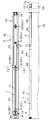
図8(a)乃至図8(c)及び図9(a)乃至図9(c)は、以上の移動補助装置つまり引込具5及びストライカー6の作動を示している。
(1)図8(a)乃至図8(c)は、引戸50が開位置から閉方向へ移動操作されている過程を示している。この過程では、図8(b)の拡大図に示すように、引込具5を構成しているラッチ3は待機姿勢となっている。このラッチ3の待機姿勢においては、付勢手段Sであるコイルバネは引き延ばされて付勢力を蓄積している。ラッチ3は、凸部33,34がケース側係止溝14b及びカバー側係止溝に係止され、それによりスライダー2を付勢手段Sの付勢力に抗して位置規制している。
図10(a)乃至図13(b)は第2実施形態の引戸補助装置を示している。この説明では、上記第1実施形態と同様の部材及び作用的に同じ部位については同じ符号を付してその説明を極力省略し、変更した構成について説明する。すなわち、第2実施形態の引戸補助装置は、第1実施形態の移動補助装置とは引込具5及び遮蔽部材7並びに受け部材8の構成自体は同じであるが、それらを引戸50の上端面51に配置した点と、ストライカー6Aの構成及びそれを本体枠側の横溝9aに配置した点とが異なっている。
図13(a)および図13(b)は、第2実施形態の引戸補助装置、つまり引込具5及びストライカー6Aの引込作動を示している。
(1)図13(a)は、引戸50を同図の矢印方向つまり開位置から閉じる方向へ移動操作している過程を想定している。ここでは、引込具5を構成しているラッチ3の待機姿勢をストライカー6と共に示している。ラッチ3の待機姿勢では、付勢手段Sであるコイルバネは引き延ばされて付勢力を蓄積している。ラッチ3は、凸部33,34がケース側係止溝14b及び不図示のカバー側係止溝に係止され、それによりスライダー2を付勢手段Sの付勢力に抗して位置規制している。
1a…誘い部
1b…案内部
10…上面
11a…付勢手段用配置部
11b…制動手段用配置部
12…側面
12a…係止部
12d…規制部
13a,13b…取付穴
14…ガイド部
14a…直線溝
14b…係止溝
15…カバー
16…誘い部
17…取付部
17a…穴
18…凹部
19…側面
19a…係合部
2…スライダー
20…上面
21…下面
22…背面
23,24…凸部
25…差込穴
26a,26b…貫通孔
27…軸部
3…ラッチ
30…上面
31…下面
32…背面
33,34…凸部
35…爪部
36…拘束部
37…枢支孔
38…係止部
39…掛止め孔
4…制動手段
40…シリンダー
41…ピストンロッド
42,43…首状係止溝
5…引込具
50…引戸(移動体に相当)
50a,50b…端面
51…上端面
6,6A…ストライカー
60…取付部
61…係合突起
62a,62b,62c…取付孔
63,64…立壁
65…嵌合溝
66…受け部
67…端面
68…取付孔
69…隙間吸収用スペーサ
7…遮光部材
70…水平部
71…遮光部
71a…端部
72…脚部
73…弾性当接部
8…受け部材
80…取付孔
81…側面
82…上面
83…下面
84…前端面
85…嵌合溝
85a…水平溝
85b…縦溝
86…座部
87…係止用縦壁
88…後端面
9…本体枠(固定体に相当)
9a…横溝
90…鴨居(横木)
91…縦木
92…枠部材
S…付勢手段
S1…鴨居(横木)
S2…両側の係止部)
Claims (3)
- ケースと前記ケース内に摺動不能に係止された待機姿勢と前記係止が解除されて摺動可能となる引込姿勢とに切り換えられるラッチ並びに付勢手段を有する引込具と、前記ラッチを待機姿勢から引込姿勢に切り換えたり引込姿勢から待機姿勢に切り換えるストライカーとを備え、前記引込具及び前記ストライカーのいずれか一方を、固定体及び前記固定体に移動可能に配置された移動体のいずれか一方に設けるとともに、前記引込具及び前記ストライカーの他方を、前記固定体及び前記移動体の他方に設け、前記ラッチが待機姿勢から引込姿勢に切り換えられると前記移動体が付勢力により移動可能となる移動補助装置において、
前記ケースは、長手方向の一端から他端の途中までを幅細となるよう切り欠かれたストライカー用の誘い部を有し、かつ、前記ラッチの一部をケース内から前記誘い部に露出配置していることを特徴とする移動補助装置。 - 前記ケースは、前記固定体又は前記移動体の対応取付部に配置される設置面を有し、前記誘い部が前記設置面を除いた部分に形成されていることを特徴とする請求項1に記載の移動補助装置。
- 前記ケースは、一端側が幅細に設けられているとともに、前記誘い部に向けて傾斜した案内部を有していることを特徴とする請求項1又は2に記載の移動補助装置。
Priority Applications (2)
| Application Number | Priority Date | Filing Date | Title |
|---|---|---|---|
| US13/701,292 US8931138B2 (en) | 2010-05-31 | 2011-05-20 | Movement assist device |
| CN201180027173.7A CN102918223B (zh) | 2010-05-31 | 2011-05-20 | 移动辅助装置 |
Applications Claiming Priority (2)
| Application Number | Priority Date | Filing Date | Title |
|---|---|---|---|
| JP2010-124143 | 2010-05-31 | ||
| JP2010124143A JP2011247053A (ja) | 2010-05-31 | 2010-05-31 | 移動補助装置 |
Publications (1)
| Publication Number | Publication Date |
|---|---|
| WO2011152232A1 true WO2011152232A1 (ja) | 2011-12-08 |
Family
ID=45066611
Family Applications (1)
| Application Number | Title | Priority Date | Filing Date |
|---|---|---|---|
| PCT/JP2011/061687 Ceased WO2011152232A1 (ja) | 2010-05-31 | 2011-05-20 | 移動補助装置 |
Country Status (4)
| Country | Link |
|---|---|
| US (1) | US8931138B2 (ja) |
| JP (1) | JP2011247053A (ja) |
| CN (1) | CN102918223B (ja) |
| WO (1) | WO2011152232A1 (ja) |
Families Citing this family (21)
| Publication number | Priority date | Publication date | Assignee | Title |
|---|---|---|---|---|
| KR101391247B1 (ko) * | 2012-07-12 | 2014-05-02 | 박윤식 | 자동 폐쇄 장치 |
| ITMI20121718A1 (it) * | 2012-10-12 | 2014-04-13 | Salice Arturo Spa | Mobile con almeno un cassetto o simile |
| WO2014169771A1 (zh) * | 2013-04-15 | 2014-10-23 | Xu Jiangde | 双管阻尼防跳上轮装置 |
| US8899703B2 (en) * | 2013-05-02 | 2014-12-02 | Nan Juen International Co., Ltd. | Pressing-type unlocking track |
| JP2015203211A (ja) * | 2014-04-14 | 2015-11-16 | 株式会社くろがね工作所 | 引戸装置 |
| TWM493587U (zh) * | 2014-08-05 | 2015-01-11 | Weider Metal Inc | 推拉門緩衝器裝置的閉合位置調整機構 |
| CA2921440A1 (en) * | 2015-07-29 | 2017-01-29 | Assa Abloy New Zealand Limited | A closure mechanism |
| US9863178B2 (en) * | 2015-08-21 | 2018-01-09 | Weider Metal Inc. | Two-way soft closing device for a sliding door and soft closing activation trigger assembly thereof |
| US10526829B2 (en) | 2015-12-03 | 2020-01-07 | Lawrence E Chaffin | Lift glide door lock assembly and lift glide window lock assembly |
| US11008775B2 (en) | 2015-12-03 | 2021-05-18 | Lawrence E Chaffin | Lift glide door lock assembly and lift glide window lock assembly and dual lift glide door lock assembly and dual lift glide window lock assembly |
| CN105507720B (zh) * | 2016-01-18 | 2018-04-06 | 王胜利 | 一种双向阻尼器及其应用的移动门 |
| WO2017157796A1 (de) * | 2016-03-16 | 2017-09-21 | Paul Hettich Gmbh & Co. Kg | Selbsteinzug und auszugsführung |
| ES2592525B1 (es) * | 2016-06-23 | 2017-09-06 | Oscar Torrabias Cantal | Pinza compacta para puertas correderas de cristal con amortiguador incorporado |
| DE102017107461A1 (de) * | 2017-04-06 | 2018-10-11 | Karl Simon Gmbh & Co. Kg | Bewegungsanordnung |
| US10292494B1 (en) * | 2017-07-03 | 2019-05-21 | Nan Jeun International Co., Ltd. | Slide rail self-return mechanism |
| DE102017123613A1 (de) * | 2017-10-11 | 2019-04-11 | Paul Hettich Gmbh & Co. Kg | Einzugsvorrichtung und Verfahren zum Öffnen und Schließen eines bewegbaren Möbelteils |
| CN107916864B (zh) * | 2017-12-22 | 2023-07-04 | 广东东泰五金精密制造有限公司 | 一种家具阻尼弹力的简易调节机构 |
| WO2019195150A1 (en) * | 2018-04-02 | 2019-10-10 | Safran Cabin Inc. | Soft self-close door damper |
| DE102019113071A1 (de) * | 2019-05-17 | 2020-11-19 | Paul Hettich Gmbh & Co. Kg | Führungsvorrichtung für ein bewegbares Möbelteil |
| CN113167092A (zh) * | 2021-03-12 | 2021-07-23 | 佛山市爱迪尔卫浴有限公司 | 用于淋浴门的双向阻尼器 |
| US11920401B2 (en) | 2021-05-03 | 2024-03-05 | Kohler Co. | Slow close mechanism for sliding applications |
Citations (3)
| Publication number | Priority date | Publication date | Assignee | Title |
|---|---|---|---|---|
| JP2004176262A (ja) * | 2002-11-22 | 2004-06-24 | Shimodaira:Kk | 引戸の戸締装置 |
| JP2009293323A (ja) * | 2008-06-06 | 2009-12-17 | Nifco Inc | 摺動補助機構 |
| JP2010090571A (ja) * | 2008-10-06 | 2010-04-22 | Kobayashi Seisakusho:Kk | 引戸のスライドアシスト装置 |
Family Cites Families (24)
| Publication number | Priority date | Publication date | Assignee | Title |
|---|---|---|---|---|
| US2744779A (en) * | 1953-08-17 | 1956-05-08 | Oscar C Rixson Co | Door holder |
| US3630560A (en) * | 1970-11-12 | 1971-12-28 | Glynn Johnson Corp | Surface-mounted nonhanded door holder |
| US4004372A (en) * | 1975-04-14 | 1977-01-25 | Doormaid, Inc. | Sliding door closer and method and apparatus for installing the same |
| US4506407A (en) * | 1983-07-18 | 1985-03-26 | Schlage Lock Company | Releasable hold-open device for a door closer |
| US5461754A (en) * | 1992-08-17 | 1995-10-31 | Dorma Gmbh + Co. Kg | Door closer with a detent for holding a door open and the detent therefor |
| US5450651A (en) * | 1993-10-15 | 1995-09-19 | Von Duprin, Inc. | End cap locking overhead mounted door holder assembly |
| US6691465B1 (en) * | 2002-03-25 | 2004-02-17 | Robert M. Stephan | Door closer assembly for sliding doors |
| JP2006063767A (ja) * | 2004-08-30 | 2006-03-09 | Shimodaira:Kk | 引戸の戸閉装置。 |
| US7430832B2 (en) * | 2004-09-22 | 2008-10-07 | Si Chien Hung | Sliding door having automatic closing structure |
| DE202005012954U1 (de) * | 2005-08-15 | 2006-07-20 | Cabinet Schranksysteme Ag | Schiebetür |
| JP5093881B2 (ja) | 2006-11-13 | 2012-12-12 | 株式会社ニフコ | 摺動補助機構及び引込ユニット |
| JP4970117B2 (ja) * | 2006-11-30 | 2012-07-04 | 株式会社ニフコ | 可動体の自走往動機構 |
| JP4980161B2 (ja) * | 2007-07-12 | 2012-07-18 | 株式会社ムラコシ精工 | 開閉体閉止装置 |
| JP5046837B2 (ja) * | 2007-10-02 | 2012-10-10 | 株式会社ニフコ | 可動体のアシスト装置 |
| JP5192831B2 (ja) * | 2008-01-17 | 2013-05-08 | 株式会社ニフコ | 引込機構 |
| WO2009091046A1 (ja) * | 2008-01-17 | 2009-07-23 | Nifco Inc. | 引込機構 |
| DE102008009046B4 (de) * | 2008-02-13 | 2014-10-02 | Günther Zimmer | Beschleunigungs- und Verzögerungsvorrichtung mit zwei Mitnahmeelementen |
| JP5428090B2 (ja) | 2008-04-18 | 2014-02-26 | スターテング工業株式会社 | 緩衝閉鎖装置 |
| US8060983B2 (en) * | 2008-09-25 | 2011-11-22 | Bortoluzzi Mobili S.R.L. | Device for cushioning an opening and closing movement of sliding shutters |
| TWI392465B (zh) * | 2008-11-20 | 2013-04-11 | King Slide Works Co Ltd | 用於滑軌組件之自動回歸裝置 |
| DE102009042486A1 (de) * | 2009-09-24 | 2011-03-31 | Dorma Gmbh + Co. Kg | Schiebetür |
| JP5588652B2 (ja) * | 2009-10-02 | 2014-09-10 | マツ六株式会社 | 引き戸クローザ |
| US8307497B2 (en) * | 2010-01-14 | 2012-11-13 | Door & Window Hardware Co. | Soft-closing device for a sliding door |
| JP2011196015A (ja) * | 2010-03-17 | 2011-10-06 | Nifco Inc | 摺動補助装置 |
-
2010
- 2010-05-31 JP JP2010124143A patent/JP2011247053A/ja active Pending
-
2011
- 2011-05-20 WO PCT/JP2011/061687 patent/WO2011152232A1/ja not_active Ceased
- 2011-05-20 CN CN201180027173.7A patent/CN102918223B/zh not_active Expired - Fee Related
- 2011-05-20 US US13/701,292 patent/US8931138B2/en not_active Expired - Fee Related
Patent Citations (3)
| Publication number | Priority date | Publication date | Assignee | Title |
|---|---|---|---|---|
| JP2004176262A (ja) * | 2002-11-22 | 2004-06-24 | Shimodaira:Kk | 引戸の戸締装置 |
| JP2009293323A (ja) * | 2008-06-06 | 2009-12-17 | Nifco Inc | 摺動補助機構 |
| JP2010090571A (ja) * | 2008-10-06 | 2010-04-22 | Kobayashi Seisakusho:Kk | 引戸のスライドアシスト装置 |
Also Published As
| Publication number | Publication date |
|---|---|
| CN102918223B (zh) | 2015-09-02 |
| CN102918223A (zh) | 2013-02-06 |
| US20130104339A1 (en) | 2013-05-02 |
| JP2011247053A (ja) | 2011-12-08 |
| US8931138B2 (en) | 2015-01-13 |
Similar Documents
| Publication | Publication Date | Title |
|---|---|---|
| WO2011152232A1 (ja) | 移動補助装置 | |
| JP5093881B2 (ja) | 摺動補助機構及び引込ユニット | |
| CN102822436B (zh) | 滑动辅助装置 | |
| CN102482904B (zh) | 滑动辅助机构及拉入单元 | |
| KR101453700B1 (ko) | 인입 장치 | |
| JP2011196015A (ja) | 摺動補助装置 | |
| JP2021536540A (ja) | スライド式パネルおよびドアのための衝撃吸収制動装置 | |
| JP5147587B2 (ja) | ロック装置 | |
| JP2006299578A (ja) | 引戸又は引出しの引込み装置 | |
| JP5926949B2 (ja) | 可動体のアシスト装置 | |
| JP5606798B2 (ja) | 引戸補助装置及び戸首付き引戸 | |
| CN204128268U (zh) | 门开关机构及移动冰箱 | |
| KR101505008B1 (ko) | 도어락 모티스의 에지볼트 조립체 | |
| JP5606799B2 (ja) | 摺動補助機構及び戸首付き引戸 | |
| JP5105629B2 (ja) | 摺動補助機構及び引込ユニット | |
| KR102354266B1 (ko) | 조립성이 개선된 슬라이더 완충장치 | |
| KR101763393B1 (ko) | 슬라이딩 도어 정위치장치 | |
| JP2003193711A (ja) | 引戸用取手 | |
| JP2001037564A (ja) | 抽斗の閉止装置 | |
| JP5976502B2 (ja) | 開閉装置 | |
| JP2015067976A (ja) | 引戸用ソフトクローズ装置 | |
| JP2013127190A (ja) | 折り畳み式扉の展開状態固定装置 | |
| JP2012062648A (ja) | 指詰め防止具 | |
| JPH0728363Y2 (ja) | 引出、扉等のラッチ装置 | |
| JP2000314266A (ja) | 引き戸用ストッパ装置 |
Legal Events
| Date | Code | Title | Description |
|---|---|---|---|
| WWE | Wipo information: entry into national phase |
Ref document number: 201180027173.7 Country of ref document: CN |
|
| 121 | Ep: the epo has been informed by wipo that ep was designated in this application |
Ref document number: 11789641 Country of ref document: EP Kind code of ref document: A1 |
|
| NENP | Non-entry into the national phase |
Ref country code: DE |
|
| WWE | Wipo information: entry into national phase |
Ref document number: 13701292 Country of ref document: US |
|
| 122 | Ep: pct application non-entry in european phase |
Ref document number: 11789641 Country of ref document: EP Kind code of ref document: A1 |