WO2011149038A1 - 立体画像印刷用印画紙、立体画像印刷物、立体画像印刷物の製造方法、及び立体画像の提供方法 - Google Patents
立体画像印刷用印画紙、立体画像印刷物、立体画像印刷物の製造方法、及び立体画像の提供方法 Download PDFInfo
- Publication number
- WO2011149038A1 WO2011149038A1 PCT/JP2011/062164 JP2011062164W WO2011149038A1 WO 2011149038 A1 WO2011149038 A1 WO 2011149038A1 JP 2011062164 W JP2011062164 W JP 2011062164W WO 2011149038 A1 WO2011149038 A1 WO 2011149038A1
- Authority
- WO
- WIPO (PCT)
- Prior art keywords
- group
- layer
- image
- carbon atoms
- substituent
- Prior art date
- Legal status (The legal status is an assumption and is not a legal conclusion. Google has not performed a legal analysis and makes no representation as to the accuracy of the status listed.)
- Ceased
Links
- 0 Cc1cc(C)c(**)cc1* Chemical compound Cc1cc(C)c(**)cc1* 0.000 description 7
- NMYVGOLIQMVNQS-RQZHXJHFSA-N CCC(CC1)CCC1OC(c1cc([s]c(/N=N\c(cc2)ccc2N(CC)CC)n2)c2[s]1)=O Chemical compound CCC(CC1)CCC1OC(c1cc([s]c(/N=N\c(cc2)ccc2N(CC)CC)n2)c2[s]1)=O NMYVGOLIQMVNQS-RQZHXJHFSA-N 0.000 description 1
- JYXRSLGWGJEJIJ-RWARQNBBSA-N CCCc(cc1)ccc1/N=C/c(cc1)ccc1/N=N/c(c(C)c1)ccc1/N=N\c(cc1)ccc1N(CC)CC Chemical compound CCCc(cc1)ccc1/N=C/c(cc1)ccc1/N=N/c(c(C)c1)ccc1/N=N\c(cc1)ccc1N(CC)CC JYXRSLGWGJEJIJ-RWARQNBBSA-N 0.000 description 1
- RXYGDPBCYCHPQW-JYZMYSRCSA-N CCN(CC)c(cc1)ccc1/N=N/c(cc1)cc(C)c1/N=N/c(cc1)ccc1/N=N/c1ccncc1 Chemical compound CCN(CC)c(cc1)ccc1/N=N/c(cc1)cc(C)c1/N=N/c(cc1)ccc1/N=N/c1ccncc1 RXYGDPBCYCHPQW-JYZMYSRCSA-N 0.000 description 1
- AIMGYPGMJAISJZ-UHFFFAOYSA-N CCN(CC)c1cc(O)c(C(C(C2c(c(O)c3)ccc3N(CC)CC)[O-])C2O)cc1 Chemical compound CCN(CC)c1cc(O)c(C(C(C2c(c(O)c3)ccc3N(CC)CC)[O-])C2O)cc1 AIMGYPGMJAISJZ-UHFFFAOYSA-N 0.000 description 1
Images








Classifications
-
- G—PHYSICS
- G03—PHOTOGRAPHY; CINEMATOGRAPHY; ANALOGOUS TECHNIQUES USING WAVES OTHER THAN OPTICAL WAVES; ELECTROGRAPHY; HOLOGRAPHY
- G03B—APPARATUS OR ARRANGEMENTS FOR TAKING PHOTOGRAPHS OR FOR PROJECTING OR VIEWING THEM; APPARATUS OR ARRANGEMENTS EMPLOYING ANALOGOUS TECHNIQUES USING WAVES OTHER THAN OPTICAL WAVES; ACCESSORIES THEREFOR
- G03B35/00—Stereoscopic photography
- G03B35/14—Printing apparatus specially adapted for conversion between different types of record
-
- B—PERFORMING OPERATIONS; TRANSPORTING
- B41—PRINTING; LINING MACHINES; TYPEWRITERS; STAMPS
- B41M—PRINTING, DUPLICATING, MARKING, OR COPYING PROCESSES; COLOUR PRINTING
- B41M3/00—Printing processes to produce particular kinds of printed work, e.g. patterns
- B41M3/06—Veined printings; Fluorescent printings; Stereoscopic images; Imitated patterns, e.g. tissues, textiles
-
- C—CHEMISTRY; METALLURGY
- C08—ORGANIC MACROMOLECULAR COMPOUNDS; THEIR PREPARATION OR CHEMICAL WORKING-UP; COMPOSITIONS BASED THEREON
- C08B—POLYSACCHARIDES; DERIVATIVES THEREOF
- C08B3/00—Preparation of cellulose esters of organic acids
- C08B3/06—Cellulose acetate, e.g. mono-acetate, di-acetate or tri-acetate
-
- C—CHEMISTRY; METALLURGY
- C08—ORGANIC MACROMOLECULAR COMPOUNDS; THEIR PREPARATION OR CHEMICAL WORKING-UP; COMPOSITIONS BASED THEREON
- C08L—COMPOSITIONS OF MACROMOLECULAR COMPOUNDS
- C08L1/00—Compositions of cellulose, modified cellulose or cellulose derivatives
- C08L1/08—Cellulose derivatives
- C08L1/10—Esters of organic acids, i.e. acylates
- C08L1/12—Cellulose acetate
-
- C—CHEMISTRY; METALLURGY
- C09—DYES; PAINTS; POLISHES; NATURAL RESINS; ADHESIVES; COMPOSITIONS NOT OTHERWISE PROVIDED FOR; APPLICATIONS OF MATERIALS NOT OTHERWISE PROVIDED FOR
- C09D—COATING COMPOSITIONS, e.g. PAINTS, VARNISHES OR LACQUERS; FILLING PASTES; CHEMICAL PAINT OR INK REMOVERS; INKS; CORRECTING FLUIDS; WOODSTAINS; PASTES OR SOLIDS FOR COLOURING OR PRINTING; USE OF MATERIALS THEREFOR
- C09D101/00—Coating compositions based on cellulose, modified cellulose, or cellulose derivatives
- C09D101/08—Cellulose derivatives
- C09D101/10—Esters of organic acids
- C09D101/12—Cellulose acetate
-
- C—CHEMISTRY; METALLURGY
- C09—DYES; PAINTS; POLISHES; NATURAL RESINS; ADHESIVES; COMPOSITIONS NOT OTHERWISE PROVIDED FOR; APPLICATIONS OF MATERIALS NOT OTHERWISE PROVIDED FOR
- C09K—MATERIALS FOR MISCELLANEOUS APPLICATIONS, NOT PROVIDED FOR ELSEWHERE
- C09K19/00—Liquid crystal materials
- C09K19/04—Liquid crystal materials characterised by the chemical structure of the liquid crystal components, e.g. by a specific unit
- C09K19/06—Non-steroidal liquid crystal compounds
- C09K19/08—Non-steroidal liquid crystal compounds containing at least two non-condensed rings
- C09K19/10—Non-steroidal liquid crystal compounds containing at least two non-condensed rings containing at least two benzene rings
- C09K19/24—Non-steroidal liquid crystal compounds containing at least two non-condensed rings containing at least two benzene rings linked by a chain containing nitrogen-to-nitrogen bonds
-
- C—CHEMISTRY; METALLURGY
- C09—DYES; PAINTS; POLISHES; NATURAL RESINS; ADHESIVES; COMPOSITIONS NOT OTHERWISE PROVIDED FOR; APPLICATIONS OF MATERIALS NOT OTHERWISE PROVIDED FOR
- C09K—MATERIALS FOR MISCELLANEOUS APPLICATIONS, NOT PROVIDED FOR ELSEWHERE
- C09K19/00—Liquid crystal materials
- C09K19/52—Liquid crystal materials characterised by components which are not liquid crystals, e.g. additives with special physical aspect: solvents, solid particles
- C09K19/60—Pleochroic dyes
- C09K19/601—Azoic
-
- G—PHYSICS
- G02—OPTICS
- G02B—OPTICAL ELEMENTS, SYSTEMS OR APPARATUS
- G02B30/00—Optical systems or apparatus for producing three-dimensional [3D] effects, e.g. stereoscopic images
- G02B30/20—Optical systems or apparatus for producing three-dimensional [3D] effects, e.g. stereoscopic images by providing first and second parallax images to an observer's left and right eyes
- G02B30/22—Optical systems or apparatus for producing three-dimensional [3D] effects, e.g. stereoscopic images by providing first and second parallax images to an observer's left and right eyes of the stereoscopic type
- G02B30/25—Optical systems or apparatus for producing three-dimensional [3D] effects, e.g. stereoscopic images by providing first and second parallax images to an observer's left and right eyes of the stereoscopic type using polarisation techniques
-
- G—PHYSICS
- G02—OPTICS
- G02B—OPTICAL ELEMENTS, SYSTEMS OR APPARATUS
- G02B30/00—Optical systems or apparatus for producing three-dimensional [3D] effects, e.g. stereoscopic images
- G02B30/20—Optical systems or apparatus for producing three-dimensional [3D] effects, e.g. stereoscopic images by providing first and second parallax images to an observer's left and right eyes
- G02B30/34—Stereoscopes providing a stereoscopic pair of separated images corresponding to parallactically displaced views of the same object, e.g. three-dimensional [3D] slide viewers
- G02B30/35—Stereoscopes providing a stereoscopic pair of separated images corresponding to parallactically displaced views of the same object, e.g. three-dimensional [3D] slide viewers using reflective optical elements in the optical path between the images and the observer
-
- G—PHYSICS
- G03—PHOTOGRAPHY; CINEMATOGRAPHY; ANALOGOUS TECHNIQUES USING WAVES OTHER THAN OPTICAL WAVES; ELECTROGRAPHY; HOLOGRAPHY
- G03B—APPARATUS OR ARRANGEMENTS FOR TAKING PHOTOGRAPHS OR FOR PROJECTING OR VIEWING THEM; APPARATUS OR ARRANGEMENTS EMPLOYING ANALOGOUS TECHNIQUES USING WAVES OTHER THAN OPTICAL WAVES; ACCESSORIES THEREFOR
- G03B35/00—Stereoscopic photography
- G03B35/18—Stereoscopic photography by simultaneous viewing
- G03B35/26—Stereoscopic photography by simultaneous viewing using polarised or coloured light separating different viewpoint images
-
- G—PHYSICS
- G03—PHOTOGRAPHY; CINEMATOGRAPHY; ANALOGOUS TECHNIQUES USING WAVES OTHER THAN OPTICAL WAVES; ELECTROGRAPHY; HOLOGRAPHY
- G03C—PHOTOSENSITIVE MATERIALS FOR PHOTOGRAPHIC PURPOSES; PHOTOGRAPHIC PROCESSES, e.g. CINE, X-RAY, COLOUR, STEREO-PHOTOGRAPHIC PROCESSES; AUXILIARY PROCESSES IN PHOTOGRAPHY
- G03C1/00—Photosensitive materials
- G03C1/76—Photosensitive materials characterised by the base or auxiliary layers
-
- C—CHEMISTRY; METALLURGY
- C09—DYES; PAINTS; POLISHES; NATURAL RESINS; ADHESIVES; COMPOSITIONS NOT OTHERWISE PROVIDED FOR; APPLICATIONS OF MATERIALS NOT OTHERWISE PROVIDED FOR
- C09K—MATERIALS FOR MISCELLANEOUS APPLICATIONS, NOT PROVIDED FOR ELSEWHERE
- C09K19/00—Liquid crystal materials
- C09K19/04—Liquid crystal materials characterised by the chemical structure of the liquid crystal components, e.g. by a specific unit
- C09K2019/0444—Liquid crystal materials characterised by the chemical structure of the liquid crystal components, e.g. by a specific unit characterized by a linking chain between rings or ring systems, a bridging chain between extensive mesogenic moieties or an end chain group
- C09K2019/0448—Liquid crystal materials characterised by the chemical structure of the liquid crystal components, e.g. by a specific unit characterized by a linking chain between rings or ring systems, a bridging chain between extensive mesogenic moieties or an end chain group the end chain group being a polymerizable end group, e.g. -Sp-P or acrylate
-
- C—CHEMISTRY; METALLURGY
- C09—DYES; PAINTS; POLISHES; NATURAL RESINS; ADHESIVES; COMPOSITIONS NOT OTHERWISE PROVIDED FOR; APPLICATIONS OF MATERIALS NOT OTHERWISE PROVIDED FOR
- C09K—MATERIALS FOR MISCELLANEOUS APPLICATIONS, NOT PROVIDED FOR ELSEWHERE
- C09K2219/00—Aspects relating to the form of the liquid crystal [LC] material, or by the technical area in which LC material are used
- C09K2219/03—Aspects relating to the form of the liquid crystal [LC] material, or by the technical area in which LC material are used in the form of films, e.g. films after polymerisation of LC precursor
-
- G—PHYSICS
- G02—OPTICS
- G02B—OPTICAL ELEMENTS, SYSTEMS OR APPARATUS
- G02B5/00—Optical elements other than lenses
- G02B5/30—Polarising elements
- G02B5/3083—Birefringent or phase retarding elements
-
- G—PHYSICS
- G03—PHOTOGRAPHY; CINEMATOGRAPHY; ANALOGOUS TECHNIQUES USING WAVES OTHER THAN OPTICAL WAVES; ELECTROGRAPHY; HOLOGRAPHY
- G03C—PHOTOSENSITIVE MATERIALS FOR PHOTOGRAPHIC PURPOSES; PHOTOGRAPHIC PROCESSES, e.g. CINE, X-RAY, COLOUR, STEREO-PHOTOGRAPHIC PROCESSES; AUXILIARY PROCESSES IN PHOTOGRAPHY
- G03C9/00—Stereo-photographic or similar processes
Definitions
- the present invention relates to a three-dimensional image printed matter that displays an image three-dimensionally, its photographic paper, its manufacturing method, and its method of providing to an observer.
- Patent Document 1 includes a configuration in which left-eye and right-eye pixels are mixed in a fixed arrangement, and a polarizing filter is provided on the upper surface of the left-eye and right-eye pixels.
- a quarter wave plate is laminated thereon, and the polarization axis of the polarizing film and the delay axis of the quarter wave plate are ⁇ 45 degrees for the left eye and for the right eye, respectively.
- a stereoscopic image printed material manufacturing method has been proposed.
- the present invention has been made in view of conventional problems, and an object thereof is to reduce crosstalk and ghost images in a three-dimensional image printed matter. More specifically, the present invention relates to a stereoscopic image printed matter with reduced crosstalk and ghost images, stereoscopic image printing paper capable of printing the stereoscopic image, a method for producing the stereoscopic image printed matter, and the stereoscopic image printed matter. It is an object of the present invention to provide a method for providing a message.
- a light-transmitting image receiving layer, a linearly polarizing layer, and a retardation layer are provided in this order, and the retardation layer fixes a composition containing a compound having refractive index anisotropy in an oriented state.
- Photographic paper [2] The photographic paper according to [1], wherein the retardation layer is formed by applying the composition by any one of a coating unit, a spraying unit, and a dropping unit. [3] The photographic paper according to [1] or [2], wherein the light-transmissive image-receiving layer is a layer formed by any one of a coating unit, a spraying unit, and a dropping unit.
- the light-transmitting image-receiving layer is an image-receiving layer capable of receiving an image by a silver salt photography method, a thermal transfer method, or an inkjet method.
- Photographic paper [5]
- the retardation layer is a 1 ⁇ 4 wavelength layer, and the in-plane slow axes of the first and second domains are each 90 °, and the in-plane slow axis of the first domain and the first
- the in-plane retardation of the first domain of the retardation layer is 0, the in-plane retardation of the second domain is 1 ⁇ 2 wavelength, the polarization axis of the linearly polarizing layer and the second axis
- the photographic paper according to any one of [1] to [4], wherein the in-plane slow axis of the domain forms an angle of 45 °.
- the linearly polarizing layer is a coating type linearly polarizing layer formed by applying a liquid crystalline composition containing a dichroic dye. Photographic paper.
- R 11 to R 14 each independently represents a hydrogen atom or a substituent;
- R 15 and R 16 each independently represents a hydrogen atom or an optionally substituted alkyl group;
- L 11 represents —N ⁇ N—, —CH ⁇ N—, —N ⁇ CH—, —C ( ⁇ O) O—, —OC ( ⁇ O) —, or —CH ⁇ CH—;
- a 11 represents Represents a phenyl group which may have a substituent, a naphthyl group which may have a substituent, or an aromatic heterocyclic group which may have a substituent;
- B 11 represents a substituent; Represents a divalent aromatic hydrocarbon group or divalent aromatic heterocyclic group which may be present;
- n represents an integer of 1 to 5, and when n is 2 or more, a plurality of B 11 are the same as each other But it may be different.
- R 21 and R 22 each represent a hydrogen atom, an alkyl group, an alkoxy group, or a substituent represented by —L 22 —Y, provided that at least one represents a group other than a hydrogen atom.
- L 22 is an alkylene group, each of two or more CH 2 groups that are not one CH 2 group or adjacent existing in the alkylene group -O -, - COO -, - OCO -, - OCOO—, —NRCOO—, —OCONR—, —CO—, —S—, —SO 2 —, —NR—, —NRSO 2 —, or —SO 2 NR— (R represents a hydrogen atom or a carbon number of 1 to 4)
- Y represents a hydrogen atom, a hydroxy group, an alkoxy group, a carboxyl group, a halogen atom, or a polymerizable group
- L 21 represents an azo group (—N ⁇ ), respectively.
- Dye represents an azo dye residue represented by the following general formula (IIa);
- * represents a bond to L 21 ;
- X 21 represents a hydroxy group, a substituted or unsubstituted alkyl group, a substituted or unsubstituted alkoxy group, an unsubstituted amino group, or a mono- or dialkylamino
- Ar 21 represents an aromatic hydrocarbon ring group or an aromatic heterocyclic group each optionally having a substituent; n represents an integer of 1 to 3, and when n is 2 or more, Two Ar 21 may be the same as or different from each other. )
- R 31 to R 35 each independently represents a hydrogen atom or a substituent
- R 36 and R 37 each independently represent a hydrogen atom or an alkyl group which may have a substituent
- Q 31 Represents an optionally substituted aromatic hydrocarbon group, aromatic heterocyclic group or cyclohexane ring group
- L 31 represents a divalent linking group
- a 31 represents an oxygen atom or a sulfur atom.
- R 41 and R 42 each represent a hydrogen atom or a substituent, and may be bonded to each other to form a ring;
- Ar 4 is an optionally substituted divalent aromatic hydrocarbon;
- R 43 and R 44 each represent a hydrogen atom or an optionally substituted alkyl group, and may be bonded to each other to form a heterocyclic ring.
- a 1 and A 2 each independently represents a substituted or unsubstituted hydrocarbon ring group or heterocyclic group.
- the method further comprises a protective layer for the linearly polarizing layer, wherein an in-plane retardation Re (550) at a wavelength of 550 nm is 0 to 10 nm between the linearly polarizing layer and the retardation layer. Printing paper of any one of [1] to [10].
- the light-transmitting image-receiving layer is an image-receiving layer capable of receiving an image by silver salt photography, and has a blue-sensitive emulsion layer, a green-sensitive emulsion layer, and a red-sensitive emulsion layer. Any one of [1] to [12].
- the light-transmitting image-receiving layer is an image-receiving layer capable of receiving an image by a thermal transfer method, and contains at least one dyeable receiving polymer.
- any photographic paper [15] Any one of [1] to [12], wherein the image receiving layer is an image receiving layer capable of receiving an image by an ink jet method, and comprises a composition containing at least a water-soluble polymer and inorganic fine particles.
- Photographic paper [16] The photographic paper according to any one of [1] to [15], wherein a distance d between the retardation layer and the image receiving layer is 500 ⁇ m or less.
- the ratio (d / p) between the distance d between the retardation layer and the image receiving layer and the distance p between the pattern boundary lines of the first and second domains is 3 or less. 1]-[16] photographic paper.
- a left-eye image and a right-eye image having parallax by a light jet method are applied to the light-transmissive image-receiving layer of the photographic paper according to any one of [1] to [13], and the retardation layer of the photographic paper.
- a method for producing a three-dimensional image printed matter comprising forming each at a position corresponding to the first domain and the second domain.
- a method for producing a three-dimensional image printed matter including: [22] The left-eye image and the right-eye image having parallax are applied to the light-transmissive image-receiving layer of the photographic paper according to any one of [1] to [12] and [15] by the inkjet method.
- a method for producing a three-dimensional image printed matter comprising: forming at respective positions corresponding to the first domain and the second domain of the retardation layer.
- a numerical range represented by using “to” means a range including numerical values described before and after “to” as a lower limit value and an upper limit value.
- Re ( ⁇ ) is the in-plane retardation value (unit: nm) at the wavelength ⁇ nm
- Rth ( ⁇ ) is the retardation value (unit: nm) in the film thickness direction at the wavelength ⁇ nm.
- the in-plane retardation (Re ( ⁇ )) is measured by making light having a wavelength of ⁇ nm incident in the normal direction of the film in KOBRA 21ADH or WR (manufactured by Oji Scientific Instruments).
- the thickness direction retardation (Rth ( ⁇ )) is a value calculated based on the value of Re ( ⁇ ) and a plurality of values measured by incidence from an oblique direction.
- visible light means 380 nm to 780 nm.
- a measurement wavelength is 550 nm.
- the angle for example, an angle such as “90 °”
- the relationship for example, “orthogonal”, “parallel”, “crossing at 45 °”, etc.
- the range of allowable error is included.
- the angle is within the range of strict angle ⁇ 10 °, and the error from the strict angle is preferably 5 ° or less, and more preferably 3 ° or less.
- patterning means that two or more regions having different optical axis directions (used to include a slow axis) are formed on a film-like (layered) object, or Means having two or more of the same region.
- crosstalk and “ghost image” are recognized as a double image and an image other than the target image when the separation of the left and right images is incomplete. That means.
- the present invention has a light-transmitting image receiving layer, a linearly polarizing layer, and a retardation layer in this order, and the retardation layer has an in-plane slow axis direction or in-plane letter.
- the present invention relates to a photographic paper for three-dimensional image printing, which is a patterning retardation layer patterned in first and second domains having different foundations. Since the photographic paper of the present invention includes a light-transmissive image receiving layer, a left-eye image and a right-eye image with a high color density and parallax can be formed. As a result, crosstalk and ghost images can be reduced as compared with the conventional example in which no image receiving layer is used.
- a dye image-receiving image-receiving layer formed by a coating means or the like it is possible to make a thin layer and to further reduce crosstalk and ghost images.
- an image receiving layer capable of receiving an image by a thermal transfer method, an inkjet method, or a silver salt photography method (particularly, a light jet method)
- a thermal head, an inkjet head, or a laser beam for image drawing is used.
- a left eye image and a right eye image having a parallax with a high color density at a desired position corresponding to the pattern of the retardation layer By controlling, it is possible to easily form a left eye image and a right eye image having a parallax with a high color density at a desired position corresponding to the pattern of the retardation layer.
- the retardation layer is a quarter wavelength layer, and the in-plane slow axes of the first and second domains are 90 ° to each other.
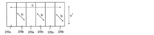
- the quarter-wave layer 16 is patterned into a first domain 16a and a second domain 16b whose respective slow axes form an angle of 90 °.
- the slow axis a of the first domain 16a is in the direction of ⁇ 45 °
- the slow axis b of the second domain 16 is in the direction of + 45 °, which are 90 ° to each other. It makes an angle.
- the slow axes a and b of the first and second domains 16a and 16b form an angle of ⁇ 45 ° with the polarization axis of the linearly polarizing layer 14, respectively.
- the polarization axis of the linearly polarizing layer 14 satisfies the above relationship regardless of the polarization axis c in the direction of 0 ° or the polarization axis c ′ in the direction of 90 °.
- FIG. 2 shows a mode in which the first and second domains 16a and 16b are sprite-shaped, but the present invention is not limited to this mode.
- An image is formed on the light transmissive image receiving layer 12 by various methods.
- the image at the position corresponding to the first domain 16a is determined by the slow axis a. Is incident on the observer's eye as a circularly polarized image in the orientation, and the image at the position corresponding to the second domain 16b is incident on the observer's eye as a circularly polarized image in the direction determined by the slow axis b.
- the slow axes a and b are orthogonal to each other, the first and second domains can be observed by an observer wearing circularly polarized glasses having polarized lenses that are aligned with each other as left and right lenses.
- the circularly polarized images from 16a and 16b can be incident only on either the left eye or the right eye. Therefore, by printing the pixels constituting the left-eye and right-eye images having parallax at the positions corresponding to the first and second domains 16a and 16b of the light-transmissive image receiving layer 12, respectively, If the image is displayed to an observer wearing circularly polarized glasses, it can be recognized as a stereoscopic image.
- the in-plane retardation of the first domain of the retardation layer is 0, and the in-plane retardation of the second domain is 1 ⁇ 2 wavelength.
- the polarization axis of the linear polarization layer and the in-plane slow axis of the second domain form an angle of 45 °.
- FIG. 3 shows a schematic cross-sectional view of an example of the printing paper of this aspect.
- the photographic paper 20A shown in FIG. 3 has a light-transmissive image receiving layer 22, a linearly polarizing layer 24, and a phase difference 26 in this order.
- the retardation layer 26 is patterned into a first domain 26a having Re of 0 nm and a second domain 26b having Re of 1 ⁇ 2 wavelength.
- the slow axis b of the second domain 26b is in the + 45 ° direction, and forms an angle of 45 ° with the polarization axis of the linearly polarizing layer 24.
- the polarization axis of the linearly polarizing layer 24 satisfies the above relationship regardless of whether it is the polarization axis c in the direction of 0 ° or the polarization axis c ′ in the direction of 90 °. .
- an image at a position corresponding to the first domain 26a has a polarization axis c of the linear polarizing layer 24.
- a linearly polarized image determined by the direction is incident on the observer's eye, and an image at a position corresponding to the second domain 26b is converted into the first domain 26a by the half-wave retardation of the second domain 26b.
- the polarized images from the first and second domains 26a and 26b are displayed on the left and right sides. It can be incident only on one of the eyes. Therefore, by printing the pixels constituting the left-eye image and the right-eye image having parallax at the positions corresponding to the first and second domains 26a, 26b of the light-transmissive image receiving layer 22, respectively, If the image is displayed to an observer wearing polarized glasses, it can be recognized as a stereoscopic image.
- the pattern shape of the left-eye and right-eye images formed on the image receiving layer is substantially the same as the shape of the first and second domains of the retardation layer. preferable. Further, it is preferable that the pattern of the left-eye image and the right-eye image formed on the photographic paper occupy the same area in the photographic paper surface. Further, it is preferable that the respective regions are evenly distributed over the whole without being biased to a part of the photographic paper surface. Since the sensitivity to the resolution of the human eye is low in the vertical direction and high in the horizontal direction, a pattern that increases the resolution in the horizontal direction is preferable.
- binocular parallax that causes depth perception corresponds to the horizontal displacement of the position of the observation target in the field of view of both the left and right eyes, so high horizontal resolution means smooth stereoscopic viewing of depth. It is also preferable from the point of giving.
- the pattern shape include horizontal stripes, diagonal stripes, vertical stripes, and checkers, preferably horizontal stripes, diagonal stripes, and checkers, and more preferably horizontal stripes and stripe inclinations with respect to the horizontal direction. 45 ° or less diagonal stripes and checkers, more preferably horizontal stripes, and stripes whose inclination is 30 ° or less with respect to the horizontal direction, more preferably horizontal stripes.
- the interval between the pattern boundary lines is preferably 10 ⁇ m or more and 5 mm or less, more preferably 30 ⁇ m or more and 2 mm or less, further preferably 50 ⁇ m or more and 1 mm or less, and still more preferably 100 ⁇ m or more and 500 ⁇ m or less.
- the pattern shape is easily visually recognized as a black pattern in the eye where the area between the boundary lines is recognized as black display, and the image quality is deteriorated.
- the distance is too small, a slight shift between the polarizer and the photographic paper pattern causes a large crosstalk, which is not preferable.
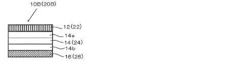
- the photographic paper 10B (or 20B) shown in FIG. 5 includes protective layers 14a and 14b that protect the linearly polarizing layer 14 (or 24).
- a polyvinyl alcohol (PVA) film or the like generally used as a linearly polarizing film is often used with its hygroscopic property and both surfaces protected by a polymer film in order to improve durability.
- PVA polyvinyl alcohol
- the linearly polarizing layer 14 (or 24) is protected by protective layers 14a and 14b made of a polymer film.
- the protective layer 14b disposed between the linearly polarizing layer 14 (or 24) and the quarter wavelength layer 16 (or the retardation layer 26) has a high retardation
- the first and second domains 16a 16b (or 26a, 26b) changes the circular polarization state of the circularly polarized image incident on the observer's eye, causing crosstalk and ghost images. Therefore, the protective layer 14b preferably has a low phase difference.
- the in-plane retardation Re (550) at a wavelength of 550 nm is preferably 0 to 10 nm, and more preferably 5 nm or less. .
- the absolute value of the sum of Rth of the quarter wavelength layer 16 and the protective layer 14b is It is preferably 20 nm or less, and more preferably 5 nm or less.
- FIG. 6 shows a schematic cross-sectional view of another example of the photographic paper according to the first and second aspects.
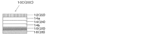
- the photographic paper 10C (or 20C) shown in FIG. 6 is an aspect in which the 1 ⁇ 4 wavelength layer 16 (or the retardation layer 26) is formed by curing a curable liquid crystalline composition, and more specifically, The quarter-wave layer 16 (or the retardation layer 26) formed by controlling the orientation of the curable liquid crystal composition and fixing the orientation by the orientation layer 15 (or 25) comprising the orientation film disposed below. It is the aspect which has.
- the alignment layer 15 exhibits an alignment regulating force due to light irradiation, and even if it is a photo-alignment film whose alignment axis is determined according to the light irradiation direction, the alignment regulating force is manifested by rubbing treatment.
- a rubbing alignment film in which the alignment axis is determined according to the rubbing treatment direction may be used.
- An example of a photo-alignment film used for the alignment layer 15 of the photographic paper 10C includes a first photo-alignment film domain and a second photo-alignment film domain having alignment axes that form an angle of 90 ° with each other by pattern exposure.
- An example of the rubbing alignment film used for the alignment layer 15 of the photographic paper 10C is a first rubbing alignment film domain and a second rubbing alignment film having an alignment axis that makes an angle of 90 ° with each other by mask rubbing treatment. This is a rubbing alignment film composed of domains.
- the rubbing alignment film 15 that is a rubbing alignment film that has been rubbed in one direction, and whose alignment regulating force changes due to a temperature change, is a first rubbing alignment film that has in-plane slow axes perpendicular to each other. Can be used to form the quarter wavelength layer 16 including the second domain and the second domain.
- the change in the alignment regulating force due to the temperature change can be achieved, for example, by changing the affinity between any two or more of the alignment film material, the liquid crystal, and the alignment control agent.
- An alignment state in which the axes are orthogonally aligned and an alignment state in which the slow axis of the liquid crystal is aligned in parallel with the rubbing direction can be realized.
- the orientation state is fixed in a predetermined pattern by ultraviolet irradiation under a photomask, and then non-irradiation at a temperature T 2 (where T 1 ⁇ T 2 ) ° C.
- T 1 ⁇ T 2 a temperature
- the first composition has an alignment control surface having different composition and different alignment control ability.
- a patterning alignment control layer including an alignment control region and a second alignment control region, wherein the respective alignment control surfaces are alternately arranged, and each of the first alignment control region and the second alignment control region
- the alignment control surface is a rubbing alignment film in which the alignment of the major axes of the liquid crystals can be controlled in a direction perpendicular to each other in a plane parallel to the alignment control surface. Details of this example will be described later.
- An example of the alignment layer 25 of the photographic paper 20C is a rubbing alignment film that has been rubbed in one direction, and an alignment film that loses the alignment regulating force when a temperature change is given.
- the alignment state is fixed in a predetermined pattern by ultraviolet irradiation under a photomask, and then at a temperature T 3 (where T 1 ⁇ T 3 ) ° C.
- T 3 where T 1 ⁇ T 3
- the non-irradiated region is brought into an isotropic phase state.
- FIG. 7 shows a schematic sectional view of another example of the photographic paper of the first and second modes.
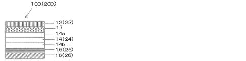
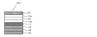
- the photographic paper 10D (or 20D) shown in FIG. 7 is aligned with the surface of the protective layer 14a of the linearly polarizing layer 14 (or 24) and the image receiving layer 12 (or 22), and then bonded with an adhesive.
- the pressure-sensitive adhesive layer 17 is provided between the protective layer 14a and the image receiving layer 12 (or 22).
- FIG. 8 shows a schematic cross-sectional view of another example of the photographic paper of the first and second modes.
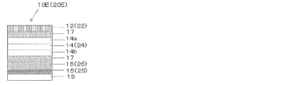
- the photographic paper 10E (or 20E) shown in FIG. 8 forms an alignment layer 15 (or 25) on the transparent support 18 and performs patterning using the alignment control ability of the alignment layer 15 (or 25).
- the four-wavelength layer 16 (or retardation layer 26) is formed to produce a laminate, and the surface of the patterned quarter-wave layer 16 (or retardation layer 26) of the laminate is applied to the linearly polarizing layer 14 (or 24).
- Protective layer 14b and an adhesive is provided.
- the pressure-sensitive adhesive layer 17 is provided between the protective layer 14b and the patterned quarter-wave layer 16 (or the retardation layer 26) and between the protective layer 14a and the image receiving layer 12 (or 22).
- the transparent support body 18 used for this aspect is the same as the member which can be utilized for the protective layers 14a and 14b of the linearly polarizing layer mentioned later, The preferable range is also the same.
- FIG. 9 shows a schematic sectional view of another example of the photographic paper of the first and second modes.
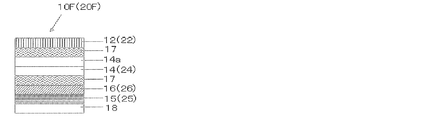
- the photographic paper 10F (or 20F) shown in FIG. 9 is formed by forming an alignment layer 15 (or 25) on the transparent support 18, and patterning using the alignment control ability of the alignment layer 15 (or 25).
- the four-wavelength layer 16 (or the retardation layer 26) is formed to produce a laminate, and the patterning of the laminate is directly applied to the surface of the quarter-wavelength layer 16 (or the retardation layer 26) of the linearly polarizing layer 14. This is an embodiment in which the surface is bonded with an adhesive.
- the pressure-sensitive adhesive layer 17 is provided between the linearly polarizing layer 14 (or 24) and the patterning quarter wavelength layer 16 (or the retardation layer 26). As will be described later, this aspect has an effect that crosstalk is further reduced because the lamination distance between the patterning quarter wavelength layer 16 (or the retardation layer 26) and the image receiving layer 12 is short.
- FIG. 10 shows a schematic cross-sectional view of another example of the photographic paper according to the first and second modes.
- the photographic paper 10G (or 20G) shown in FIG. 10 has no protective layer on any surface, and the surface of the linearly polarizing layer 14 (or 24) is bonded to the surface of the image receiving layer 12 with an adhesive. It is an aspect. In this aspect, the stacking distance between the patterned quarter-wave layer 16 (or the retardation layer 26) and the image receiving layer 12 is further reduced, so that crosstalk is further reduced.
- FIG. 11 shows a schematic cross-sectional view of another example of the photographic paper of the first and second modes.
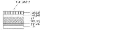
- the photographic paper 10H (or 20H) shown in FIG. 11 is an embodiment in which the image receiving layer 12 (or 22) is directly formed on the surface of the linearly polarizing layer 14 (or 24) by a coating means or the like.
- FIG. 12 shows a schematic cross-sectional view of another example of the photographic paper of the first and second modes.
- an alignment layer 15 ′ is formed on the surface of the patterning quarter wavelength layer 16 (or the retardation layer 26), and the dichroism is formed on the surface of the alignment layer 15 ′.
- a polarizing material such as a liquid crystal composition containing a dye is applied by coating or the like, and the coating type polarizing layer 14 ′ (or 24 ′) is formed by the alignment control ability of the alignment layer 15 ′.
- the alignment layer 15 ′ exhibits an alignment regulating force by light irradiation, and even if it is a photo-alignment film in which the alignment axis is determined according to the light irradiation direction, the alignment regulating force is manifested by rubbing treatment. May be a rubbing alignment film in which the alignment axis is determined according to the rubbing treatment direction.
- the photographic papers 10C to 10I or 20C to 20I shown in FIGS. 6 to 12 use the alignment regulating force of the alignment layer 15 to make the quarter wavelength layer 16 composed of the first domain 16a and the second domain 16b, Alternatively, an alignment film is used to form the retardation layer 26 composed of the first domain 26a and the second domain 26b.
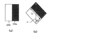
- An example of a method for producing the photo-alignment film 15 for forming the quarter wavelength layer 16 is as follows. First, the composition for photo-alignment films is applied to the surface of the linearly polarizing layer 14 to form a film. Next, linearly polarized light is irradiated using a wire grid. Specifically, first, as shown in FIG.
- a wire grid polarizer is set in a direction 1 that forms 45 degrees with the polarization axis c of the linearly polarizing layer 14, and a mask A (black portion in the figure) is set. Is a light shielding portion, and a white portion is a light transmitting portion (the same applies to the mask B).
- a wire grid polarizer is set in a direction 2 that forms 45 degrees with the polarization axis c of the linearly polarizing layer 14, and exposure is performed through a mask B.
- the first and second photo-alignment film domains can be formed in which the alignment axes are in the direction of ⁇ 45 ° and are orthogonal to each other.
- the liquid crystal on the first photo-alignment film domain is aligned according to the alignment axis
- the liquid crystal on the second photo-alignment film domain is Align according to the alignment axis.
- the slow axes a and b are 90 ° to each other as shown in FIG. 2, and ⁇ 45 ° to the polarization axis c of the linearly polarizing layer 14, respectively.
- the quarter wavelength layer 16 composed of the first and second domains 16a and 16b forming the following can be formed.
- the photographic paper of this embodiment in which a quarter wavelength layer is formed using a photo-alignment film has a slow axis of 90 ° with respect to the linearly polarizing layer by pattern exposure that is relatively easy to control such as alignment. Since it has a quarter wavelength layer that forms ⁇ 45 ° with respect to the polarization axis, the axis deviation (for example, the axis deviation between the slow axes of the quarter wavelength layer, and the slow axis and the polarization axis of the linear polarization layer).
- the three-dimensional image formed on the photographic paper of this aspect is further reduced in crosstalk and ghost images.
- the photographic paper of the present invention does not need to have all the layers fixed, and may be configured to be removable.
- the layers may be laminated in a predetermined order.
- Light transmissive image receiving layer The image receiving layer according to the present invention is light transmissive. Specifically, the light transmittance is preferably 70% or more, more preferably 80% or more, and particularly preferably 90% or more.
- a dye image-receiving image-receiving layer formed by any one of a coating unit, a spraying unit, and a dropping unit can form an image with a higher color density and further reduce the occurrence of crosstalk and ghosting. It is preferable because it is possible.
- the “image receiving layer” is an image receiving layer capable of receiving an image composed of a dye or the like, and accepts red, green, and blue photosensitive emulsions such as reversal, A layer that forms an image by a jet method or the like, or a layer that accepts a dye that is transferred as in thermal transfer, or a layer that forms an image by accepting a dye that has been ejected as in an ink jet method To do.
- the image receiving layer it is preferable to use an image receiving layer capable of receiving an image by a silver salt photographic method (particularly, a light jet method), a thermal transfer method, or an ink jet method.
- Image receiving layer capable of receiving images with silver halide photographs it is preferable to use an image receiving layer capable of receiving an image by silver salt photography. It is particularly preferable to use a reversal film capable of receiving an image by the light jet method. When using a reversal film, the laser beam etc. are controlled, and the left eye and right eye are positioned at the correct positions corresponding to the first and second domains of the retardation layer based on the digitized image data. Images can be formed with high image density, and crosstalk and ghost images can be reduced. Even if an image receiving layer capable of receiving an image by an inkjet method or a thermal transfer method described later is used, it contributes to the reduction of crosstalk and ghost images.
- the image receiving layer capable of receiving an image by a silver salt photograph that can be used in this embodiment is preferably a reversal film.
- Various reversal films can be selected. Among them, a reversal film capable of drawing based on digital data and capable of drawing a light jet is preferable.
- the reversal film used preferably has a high OD (optical density), specifically 3 or more.
- the OD of the photographic paper for ink jet and thermal transfer is about 1.2, and is preferably higher than those ODs.
- An example of an image-receiving layer capable of receiving an image by a silver salt photograph that can be used in this embodiment is a reversal film that can be drawn with a laser by a light jet method, and a blue-sensitive emulsion layer on a light-transmitting support.
- a silver halide color reversal film for full color having a green photosensitive emulsion layer and a red photosensitive emulsion layer. This example is described in detail in JP-A-10-232470 and JP-A-2002-40604, and can be used in the present invention.
- Fujichrome Velvia 50 Professional RVP50 Fujichrome T64 Professional
- Fujichrome PROVIA 100F Professional Fujichrome PROVIA 400X Professional
- Fujichrome ASTIA 100F Professional Fujichrome Sensia III 100
- Fujichrome Velvia 100 Professionals such as Fujichrome TREBI 100C can also be used.
- Thermal transfer image receiving layer There is no particular limitation on the image-receiving layer (heat-sensitive transfer image-receiving layer) that can receive an image by the thermal transfer method usable in the present invention.
- Various heat-sensitive transfer image-receiving layers can be used. It is preferable to contain as a main component a resin (a dye-receptive polymer) that is easy to be dyed in order to accept the dye transferred from the transfer ink sheet during thermal transfer and maintain the formed image.
- a resin a dye-receptive polymer
- the material of the heat-sensitive transfer image receiving layer include polyester resin, polycarbonate resin, vinyl chloride resin, cellulose resin and the like.
- a heat-sensitive transfer image-receiving layer containing a polymer having a repeating unit represented by the following general formula [1] is preferable because of excellent transfer sensitivity and image storage stability.
- the polymer may be contained as a latex.
- R 1 represents a hydrogen atom, a halogen atom or a methyl group
- L 1 represents a divalent linking group
- R 2 represents an alkylene group having 1 to 5 carbon atoms.
- n represents an integer of 1 to 40.
- Z 1 represents a hydrogen atom or a linear, branched or cyclic aliphatic hydrocarbon group having 1 to 30 carbon atoms.
- the alkylene group in R 2 and the aliphatic hydrocarbon group in Z 1 may have a substituent, and when n is 2 or more, the plurality of R 2 may be the same as or different from each other.
- R 1 represents a halogen atom, it is preferably a chlorine atom or a fluorine atom.
- An alkylene group, an arylene group, or a divalent linking group formed by combining two or more of these is preferable, and may have a group or a substituent represented by —C ( ⁇ O) —X—.
- X represents an oxygen atom, a sulfur atom or —N (R 0 ) —
- R 0 represents a hydrogen atom or a substituent (preferably the alkyl group, cycloalkyl group, aryl group or hetero group as the substituent).
- L 1 is most preferably —C ( ⁇ O) —O—.
- the alkylene group for R 2 may be chained or branched, but is preferably chained.
- the number of carbon atoms is preferably 2-4.
- n is preferably an integer of 1 to 30, more preferably an integer of 1 to 20, and most preferably an integer of 1 to 10.
- Examples of the aliphatic hydrocarbon group for Z 1 include an alkyl group, an alkenyl group, an alkynyl group, a cycloalkyl group, a cycloalkenyl group, and a cycloalkynyl group, and an alkyl group, an alkenyl group, a cycloalkyl group, and a cycloalkenyl group include Preferably, an alkyl group and a cycloalkyl group are more preferable, and an alkyl group is more preferable.
- the alkenyl group and alkynyl group have 2 to 30 carbon atoms (preferably 2 to 20 carbon atoms), the cycloalkyl group has 3 to 30 carbon atoms (preferably 5 to 20 carbon atoms), and the cycloalkynyl group has 6 to 30 carbon atoms (preferably 6 to 6 carbon atoms). 20) is preferred respectively.
- the alkyl group preferably has 1 to 20 carbon atoms.
- Z 1 is preferably a hydrogen atom or an aliphatic group in the above preferred range, more preferably a hydrogen atom or an alkyl group.
- the substituent or the substituent in “may have a substituent” used in each general formula including the general formula [1] will be described.
- any substituent may be used, but a substituent selected from the following substituent group is preferred.
- alkyl group preferably an alkyl group having 1 to 20 carbon atoms, more preferably 1 to 12 carbon atoms, particularly preferably 1 to 8 carbon atoms, such as a methyl group, an ethyl group, an isopropyl group, a tert-butyl group, n-octyl group, n-decyl group, n-hexadecyl group, cyclopropyl group, cyclopentyl group, cyclohexyl group and the like), alkenyl group (preferably having 2 to 20 carbon atoms, more preferably 2 to 12 carbon atoms, Particularly preferred are alkenyl groups having 2 to 8 carbon atoms, including, for example, vinyl group, aryl group, 2-butenyl group, 3-pentenyl group and the like, and alkynyl groups (preferably having 2 to 20 carbon atoms, more preferably Is an alkynyl group having 2 to 12 carbon
- An aryl group preferably an aryl group having 6 to 30 carbon atoms, more preferably 6 to 20 carbon atoms, particularly preferably 6 to 12 carbon atoms, such as a phenyl group, a p-methylphenyl group, and a naphthyl group.
- a substituted or unsubstituted amino group preferably an amino group having 0 to 20 carbon atoms, more preferably 0 to 10 carbon atoms, and particularly preferably 0 to 6 carbon atoms).
- An alkoxy group (preferably an alkoxy group having 1 to 20 carbon atoms, more preferably 1 to 16 carbon atoms, particularly preferably 1 to 10 carbon atoms, and examples thereof include a methoxy group, an ethoxy group, and a butoxy group).
- alkoxycarbonyl group preferably an alkoxycarbonyl group having 2 to 20 carbon atoms, more preferably 2 to 16 carbon atoms, particularly preferably 2 to 10 carbon atoms such as a methoxycarbonyl group and an ethoxycarbonyl group
- acyloxy A group preferably an acyloxy group having 2 to 20 carbon atoms, more preferably 2 to 16 carbon atoms, particularly preferably 2 to 10 carbon atoms such as an acetoxy group and a benzoyloxy group
- an acylamino group preferably Having 2 to 20 carbon atoms, more preferably 2 to 16 carbon atoms, particularly preferably 2 to 10 carbon atoms.
- a silamino group such as acetylamino group and benzoylamino group
- alkoxycarbonylamino group preferably having 2 to 20 carbon atoms, more preferably 2 to 16 carbon atoms, particularly preferably 2 to 12 carbon atoms.
- An alkoxycarbonylamino group such as a methoxycarbonylamino group
- an aryloxycarbonylamino group preferably having 7 to 20 carbon atoms, more preferably 7 to 16 carbon atoms, and particularly preferably 7 to 12 carbon atoms).
- Aryloxycarbonylamino group such as phenyloxycarbonylamino group), sulfonylamino group (preferably having 1 to 20 carbon atoms, more preferably 1 to 16 carbon atoms, particularly preferably 1 to carbon atoms). 12 sulfonylamino groups such as methanesulfonyl And a sulfamoyl group (preferably a sulfamoyl group having 0 to 20 carbon atoms, more preferably 0 to 16 carbon atoms, and particularly preferably 0 to 12 carbon atoms, such as sulfamoyl group).
- carbamoyl group preferably having 1 to 20 carbon atoms, more preferably 1 to 16 carbon atoms, and particularly preferably carbon number. 1 to 12 carbamoyl groups, for example, unsubstituted carbamoyl group, methylcarbamoyl group, diethylcarbamoyl group, phenylcarbamoyl group, etc.
- An alkylthio group preferably an alkylthio group having 1 to 20 carbon atoms, more preferably 1 to 16 carbon atoms, particularly preferably 1 to 12 carbon atoms, such as a methylthio group and an ethylthio group
- an arylthio group An arylthio group having 6 to 20 carbon atoms, more preferably 6 to 16 carbon atoms, and particularly preferably 6 to 12 carbon atoms, and a sulfonyl group (preferably having a carbon number of 1 to 12) are preferable.
- Zensulfinyl groups, etc. ureido groups (preferably ureido groups having 1 to 20 carbon atoms, more preferably 1 to 16 carbon atoms, particularly preferably 1 to 12 carbon atoms, such as unsubstituted ureido groups) A methylureido group, a phenylureido group, etc.), a phosphoric acid amide group (preferably a phosphoric acid amide group having 1 to 20 carbon atoms, more preferably 1 to 16 carbon atoms, particularly preferably 1 to 12 carbon atoms).
- diethyl phosphoric acid amide group, phenyl phosphoric acid amide group, etc. hydroxy group, mercapto group, halogen atom (for example, fluorine atom, chlorine atom, bromine atom, iodine atom), cyano group, sulfo group, Carboxyl group, nitro group, hydroxamic acid group, sulfino group, hydrazino group, imino group, heterocyclic group (preferably having 1 to 0, more preferably 1 to 12 heterocyclic group, for example, a heterocyclic group having a heteroatom such as nitrogen atom, oxygen atom, sulfur atom, etc., for example, imidazolyl group, pyridyl group, quinolyl group, furyl group , Piperidyl group, morpholino group, benzoxazolyl group, benzimidazolyl group, benzthiazolyl group, etc.), silyl group (preferably having 3 to 40 carbon
- the monomer represented by the general formula [1] is preferably a monomer represented by the following general formula [2].
- R 3 represents a hydrogen atom, a halogen atom or a methyl group
- X represents an oxygen atom, a sulfur atom or —N (Rc) —.
- Rc represents a hydrogen atom or an optionally substituted alkyl group or cycloalkyl group having 1 to 8 carbon atoms.
- R 4 represents an alkylene group having 1 to 5 carbon atoms.
- m represents an integer of 1 to 40.
- Z 2 represents a hydrogen atom or a linear, branched or cyclic aliphatic hydrocarbon group having 1 to 30 carbon atoms.
- the alkyl group in Rc, the cycloalkyl group, the alkylene group in R 4 , and the aliphatic hydrocarbon group in Z 2 may have a substituent, and when m is 2 or more, a plurality of R 4 may be the same May be different.
- R 3 , R 4 , m and Z 2 are the same as R 1 , R 2 , n and Z 1 in the corresponding general formula [1], respectively, and preferred ranges are also the same.
- X is preferably an oxygen atom.
- the alkyl group represented by Rc preferably has 3 to 8 carbon atoms, and the cycloalkyl group represented by Rc preferably has 3 to 8 carbon atoms.
- the monomer represented by the general formula [1] or [2] is more preferably a monomer represented by the following general formula [3].
- R 5 represents a hydrogen atom, a halogen atom or a methyl group
- R 6 represents an alkylene group having 2 to 4 carbon atoms.
- l represents an integer of 1 to 40.
- Z 3 represents a hydrogen atom or a linear, branched or cyclic aliphatic hydrocarbon group having 1 to 20 carbon atoms.
- the alkylene group in R 6 and the aliphatic hydrocarbon group in Z 3 may have a substituent, and when l is 2 or more, the plurality of R 4 may be the same as or different from each other.
- R 5 , R 6 and l have the same meanings as R 1 , R 2 and n in the corresponding general formula [1], and preferred ranges are also the same.
- Z 3 is the same as the preferable range in the range included in Z 1 in the general formula [1].
- Preferable examples of the monomers represented by the general formulas [1] to [3] include [0035] to [0037] in JP-A-2008-105397 and [0030] to [0030] in JP-A-2008-105398. [0033] The compounds described in [0033] are included. In addition, since the monomers represented by the above general formulas [1] to [3] are commercially available as Nippon Oil and Fat's Blemmer series and Toa Gosei's Aronix series, the commercially available products can also be used.
- the polymer having a repeating unit derived from the monomers represented by the general formulas [1] to [3] may be a copolymer with another monomer.
- examples of other monomers include those described in JP-A-2008-105397, [0039] to [0042], and preferred examples are also the same.
- Specific examples of the polymer include the polymers described in [0043] to [0047] of the same publication.
- the polymer may be contained in the heat-sensitive transfer image-receiving layer as a polymer latex, and the polymer latex may be a monomer represented by the general formulas [1] to [3], It is preferably a copolymer with other monomers.
- Examples of other monomers constituting the polymer latex include other monomers described in [0035] to [0048] of JP-A-2008-105398, and preferred examples are also the same.
- Preferred examples of the polymer latex include the copolymers described in [0053] to [0057] of the same publication, and details of the polymer latex are described in [0049] to [0051] of the same publication. This is the same as the embodiment.
- the image-receiving layer may contain at least one other polymer and / or other polymer latex together with the polymer and polymer latex containing the repeating unit of the monomer represented by the general formula [1].
- other polymers and / or other polymer latexes that can be used in combination include [0049] to [0074] of JP-A-2008-105397 and [0059] to [0075] of JP-A-2008-105398. Examples are included.
- the image receiving layer can be formed by applying a coating composition containing a main component polymer such as a polymer containing a repeating unit of the monomer represented by the general formula [1] on the surface and drying it.
- a coating composition containing a main component polymer such as a polymer containing a repeating unit of the monomer represented by the general formula [1]
- an organic solvent for example, methyl ethyl ketone and toluene
- a mixed solvent of water and an organic solvent may be used.
- 1 or more types of additives such as a ultraviolet absorber, a mold release agent, and antioxidant, may be contained with the said main component polymer.
- the ultraviolet absorber and the antioxidant are added for the purpose of improving the durability of the image receiving layer.
- the release agent is added for the purpose of preventing thermal fusion with the thermal transfer sheet laminated during image formation.
- the releasing agent include silicone oil and phosphoric ester plasticizer fluorine compound, and silicone oil is particularly preferably used.
- silicone oil modified silicone oils such as epoxy modification, alkyl modification, amino modification, carboxyl modification, alcohol modification, fluorine modification, alkylaralkyl polyether modification, epoxy / polyether modification, and polyether modification are preferably used.
- a reaction product of vinyl-modified silicone oil and hydrogen-modified silicone oil is preferable.
- the addition amount of the release agent is preferably 0.2 to 30 parts by mass with respect to the main component polymer.
- the image receiving layer can be formed by applying the coating composition to the surface of an arbitrary member and drying it.
- the coating can be performed by a known coating method such as an extrusion die coater, an air doctor coater, a bread coater, a rod coater, a knife coater, a squeeze coater, a reverse roll coater, or a bar coater.
- a known coating method such as an extrusion die coater, an air doctor coater, a bread coater, a rod coater, a knife coater, a squeeze coater, a reverse roll coater, or a bar coater.
- 0.5 to 10 g / m 2 (in terms of solid content) is preferable.
- the film thickness of the image transfer layer for thermal transfer is not limited. In general, the thickness is preferably 1 to 20 ⁇ m.
- the heat-sensitive transfer image receiving layer may be a laminate of two or more layers, for example, a laminate of an image receiving layer containing the polymer and an intermediate layer.
- the intermediate layer is preferably disposed between the linearly polarizing layer.
- the intermediate layer is intended to improve the adhesion for the purpose of adjusting the charge for the purpose of preventing deterioration of the linearly polarizing layer disposed under the image receiving layer due to heat from the thermal head during thermal transfer. Or for the purpose of improving print sensitivity.
- the intermediate layer is described in detail in [0085] to [0097] of JP-A-2008-105397, and can be referred to.
- Two or more intermediate layers may be formed according to the purpose. In the embodiment having an intermediate layer, it is preferable that the image receiving layer and at least one intermediate layer are simultaneously coated by a simultaneous multilayer coating method and dried.
- the image receiving layer (inkjet image receiving layer) capable of receiving an image by the inkjet method usable in the present invention.
- Various inkjet image receiving layers can be used.
- the ink-jet image receiving layer is preferably made of a material that is easy to be dyed in order to receive the dye in the ink landed by the ink-jet method and maintain the formed image.
- an image receiving layer made of a composition containing inorganic fine particles and a water-soluble resin is preferable.
- the image receiving layer containing inorganic fine particles and a water-soluble resin is coated on the surface of an arbitrary member with a solution containing at least inorganic fine particles and a water-soluble resin (hereinafter sometimes referred to as an “image receiving layer forming liquid”). Then, it can be formed by drying.
- the coating method of the image-receiving layer forming liquid can be carried out according to various methods similar to the coating method of the coating composition for forming the heat-sensitive transfer image-receiving layer.
- an extrusion die coater an air It can be performed by a known coating method such as a doctor coater, a bread coater, a rod coater, a knife coater, a squeeze coater, a reverse roll coater, or a bar coater.
- the coating layer is applied simultaneously with the application of the image-receiving layer-forming liquid or during the drying of the coating layer formed by applying the image-receiving layer-forming liquid and before the coating layer shows a reduction rate drying.
- a basic solution having a pH of 7.1 or higher it is preferable to apply a basic solution having a pH of 7.1 or higher. That is, the image-receiving layer is preferably produced by introducing a basic solution having a pH of 7.1 or higher after applying the image-receiving layer-forming solution while the coating layer exhibits constant rate drying.
- the basic solution having a pH of 7.1 or higher can contain a crosslinking agent or the like as necessary.
- the basic solution having a pH of 7.1 or higher can promote the hardening of the image receiving layer when used as an alkaline solution, preferably has a pH of 7.5 or higher, and particularly preferably has a pH of 7.9 or higher. If the pH is too close to the acidic side, the crosslinking reaction of the water-soluble resin by the crosslinking agent is not sufficiently performed, and bronzing may occur or defects such as cracks may occur in the image receiving layer.
- a basic solution having a pH of 7.1 or higher is obtained by, for example, adding ion-exchanged water, a metal compound (for example, 1 to 5%) and a basic compound (for example, 1 to 5%), and, if necessary, p-toluenesulfonic acid (for example, 0.5 to 3%) can be added and sufficiently stirred.
- all "%" of each composition means solid content mass%.
- “before the coating layer exhibits reduced-rate drying” usually refers to a process for several minutes immediately after coating of the coating solution. During this period, the solvent (dispersion medium) in the coated coating layer It shows the phenomenon of “constant rate drying” in which the content decreases in proportion to time. The time for indicating “constant rate drying” is described in, for example, the Chemical Engineering Handbook (pages 707 to 712, published by Maruzen Co., Ltd., 1980).
- the coating layer is dried until it shows reduced drying.
- This drying is generally performed at 40 to 180 ° C. for 0.5 to 10 minutes (preferably 0.5%). ⁇ 5 minutes).
- the drying time naturally varies depending on the coating amount, but usually the above range is appropriate.
- the layer thickness of the image receiving layer formed by drying the image receiving layer forming liquid needs to have an absorption capacity sufficient to absorb all ink droplets, and is determined in relation to the porosity in the layer. There is a need. For example, if the ink amount is 8 nL / mm 2 and the porosity is 60%, a film having a layer thickness of about 15 ⁇ m or more is required. Considering this point, the thickness of the image receiving layer is preferably 10 to 50 ⁇ m.
- the pore diameter of the image receiving layer is preferably 0.005 to 0.030 ⁇ m, more preferably 0.01 to 0.025 ⁇ m in terms of median diameter. The porosity and pore median diameter can be measured using a mercury porosimeter (Bore Sizer 9320-PC2 manufactured by Shimadzu Corporation).
- inorganic fine particles examples include silica fine particles, colloidal silica, titanium dioxide, barium sulfate, calcium silicate, zeolite, kaolinite, halloysite, mica, talc, calcium carbonate, magnesium carbonate, calcium sulfate, boehmite, pseudoboehmite and the like. be able to. Among these, silica fine particles are preferable.
- the silica fine particles have a particularly large specific surface area, the ink absorbency and retention efficiency are high, and the refractive index is low. Therefore, if the dispersion is performed to an appropriate fine particle diameter, transparency can be imparted to the image receiving layer. There is an advantage that high color density and good color developability can be obtained. Thus, the fact that the image receiving layer is transparent is important from the viewpoint of obtaining a high color density, good color developability and glossiness.
- the average primary particle size of the inorganic fine particles is preferably 20 nm or less, more preferably 15 nm or less, and particularly preferably 10 nm or less.
- the specific surface area by BET method of the inorganic fine particles 200 meters 2 / g or more is preferable, 250 meters 2 / g or more and more preferably, 380 m 2 / g or more is particularly preferable.
- the specific surface area of the inorganic fine particles is 200 or more m 2 / g, the transparency of the image receiving layer is high and the printing density can be kept high.
- the BET method referred to in the present invention is one of powder surface area measurement methods by vapor phase adsorption, and is a method for determining the total surface area of a 1 g sample, that is, the specific surface area from the adsorption isotherm.
- nitrogen gas is often used as the adsorbed gas, and the most frequently used method is to measure the amount of adsorption from the change in pressure or volume of the gas to be adsorbed.
- the most prominent expression for expressing the isotherm of multimolecular adsorption is the Brunauer, Emmett, and Teller equation, called the BET equation, which is widely used for determining the surface area.
- the adsorption amount is obtained based on the BET equation, and the surface area is obtained by multiplying the area occupied by one adsorbed molecule on the surface.
- the silica fine particle has a silanol group on the surface thereof, and the particles are likely to adhere to each other due to the hydrogen bond of the silanol group, and because of the adhesion effect between the particles via the silanol group and the water-soluble resin,
- the average primary particle size is 20 nm or less
- the void ratio of the image receiving layer is large, a highly transparent structure can be formed, and the ink absorption characteristics can be effectively improved.
- silica fine particles are generally roughly classified into wet method particles and dry method (gas phase method) particles according to the production method.
- a method is mainly used in which activated silica is produced by acid decomposition of a silicate, and this is appropriately polymerized and agglomerated and precipitated to obtain hydrous silica.
- the gas phase method is a method by high-temperature gas phase hydrolysis of silicon halide (flame hydrolysis method), a method in which silica sand and coke are heated and reduced by an arc in an electric furnace and oxidized with air.
- the method of obtaining anhydrous silica by the (arc method) is the mainstream, and “gas phase method silica” refers to anhydrous silica fine particles obtained by the gas phase method.
- Vapor phase method silica is different from the above hydrous silica in the density of silanol groups on the surface, the presence or absence of vacancies, etc., and shows different properties, but is suitable for forming a three-dimensional structure with high porosity.
- the reason for this is not clear, but in the case of hydrous silica, the density of silanol groups on the surface of the fine particles is as high as 5 to 8 / nm 2 and the silica fine particles tend to aggregate (aggregate) easily.
- the density of silanol groups on the surface of the fine particles is as small as 2 to 3 / nm 2 , so that it becomes sparse soft aggregation (flocculate), and as a result, it is estimated that the structure has a high porosity.
- vapor phase silica fine particles obtained by the dry method are preferred, and silica fine particles having a density of 2 to 3 silanol groups / nm 2 on the fine particle surface are more preferred.
- the inorganic fine particles most preferably used in the present invention are vapor phase silica having a specific surface area of 200 m 2 / g or more by the BET method.
- Water-soluble resin examples include polyvinyl alcohol resins that are resins having a hydroxy group as a hydrophilic group [polyvinyl alcohol (PVA), acetoacetyl-modified polyvinyl alcohol, cation-modified polyvinyl alcohol, anion-modified polyvinyl alcohol, silanol-modified polyvinyl.
- PVA polyvinyl alcohol
- acetoacetyl-modified polyvinyl alcohol acetoacetyl-modified polyvinyl alcohol
- cation-modified polyvinyl alcohol anion-modified polyvinyl alcohol
- silanol-modified polyvinyl silanol-modified polyvinyl.
- cellulose resins methyl cellulose (MC), ethyl cellulose (EC), hydroxyethyl cellulose (HEC), carboxymethyl cellulose (CMC), hydroxypropyl cellulose (HPC), hydroxyethyl methyl cellulose, hydroxypropyl methyl cellulose, etc.
- PAAM polyacrylamide
- PVP polyvinyl pyrrolidone
- polyacrylic acid hydrazide etc.
- polyvinyl alcohol resins are particularly preferable.
- examples of the polyvinyl alcohol resin include Japanese Patent Publication No. 4-52786, Japanese Patent Publication No. 5-67432, Japanese Patent Publication No. 7-29479, Japanese Patent No. 2537827, Japanese Patent Publication No. 7-57553, Japanese Patent No. 2502998, and Japanese Patent No. 3053231.
- the content of the water-soluble resin used in the present invention is preferably 9 to 40% by mass, more preferably 12 to 33% by mass, based on the total solid content of the image receiving layer.
- Each of the inorganic fine particles and the water-soluble resin mainly constituting the image receiving layer may be a single material, or a mixed system of a plurality of materials may be used. From the viewpoint of improving the printing density while maintaining transparency, the type of water-soluble resin combined with the inorganic fine particles is important.
- the water-soluble resin is preferably a polyvinyl alcohol resin, more preferably a polyvinyl alcohol resin having a saponification degree of 70 to 100%, and even more preferably a polyvinyl alcohol resin having a saponification degree of 80 to 99.5%.
- the polyvinyl alcohol resin may be used in combination with a water-soluble resin other than the polyvinyl alcohol resin.
- the content of the polyvinyl alcohol resin in the total water-soluble resin is preferably 50% by mass or more, and more preferably 70% by mass or more.
- the image receiving layer in the present invention prevents a decrease in film strength and cracks during drying caused by the PB ratio being too large, and the When the PB ratio is too small, the gap is likely to be blocked by the resin, and from the viewpoint of preventing the ink absorbency from being lowered due to the decrease in the void ratio, 1.5: 1 to 10: 1 is preferable. .
- the image receiving layer Since stress may be applied to the photographic paper when passing through the conveyance system of the image recording apparatus, the image receiving layer needs to have sufficient film strength. Further, when the photographic paper is cut into a sheet, the image receiving layer needs to have sufficient film strength in order to prevent the image receiving layer from being cracked or peeled off.
- the mass content ratio (x: y) is more preferably 5: 1 or less, while it is 2: 1 or more from the viewpoint of ensuring high-speed ink absorbability, for example, in an inkjet printer. It is more preferable.
- a solution in which gas phase method silica having an average primary particle size of 20 nm or less and a water-soluble resin are completely dispersed in an aqueous solution at a mass content ratio (x: y) of 2: 1 to 5: 1 is placed on a support.
- x: y mass content ratio
- a three-dimensional network structure in which the secondary particles of silica fine particles are network chains is formed, the average pore diameter is 30 nm or less, the porosity is 50 to 80%, the pore specific volume Can be easily formed with a translucent porous film having a specific surface area of 100 m 2 / g or more.
- the image-receiving layer forming liquid can be prepared as follows, for example.
- vapor phase silica and a dispersant are added to water (for example, 10 to 20% by mass of vapor phase silica in water), and a counter collision type high pressure homogenizer (for example, ( After being dispersed under a high pressure condition of, for example, 120 MPa (preferably 100 to 200 MPa) using a “Sumino Machine Co., Ltd.”), a boron compound and a PVA aqueous solution (for example, about 1/3 of the above-mentioned gas phase method silica)
- the PVA can be prepared by adding other ingredients and stirring.
- the obtained image-receiving layer-forming liquid is in a uniform sol state, and a porous image-receiving layer having a three-dimensional network structure can be formed by coating this on a support.
- Dispersers used for obtaining the aqueous dispersion include various types of conventionally known dispersion machines such as a high-speed rotating disperser, a medium stirring disperser (such as a ball mill and a sand mill), an ultrasonic disperser, a colloid mill disperser, and a high pressure disperser.
- a stirrer-type disperser, a colloid mill disperser or a high-pressure disperser is preferable from the viewpoint of efficiently dispersing the formed fine particles.
- an orifice passing type high-pressure disperser are preferred.
- water, an organic solvent, or a mixed solvent thereof can be used as the solvent in the above preparation.
- the organic solvent that can be used for this coating include alcohols such as methanol, ethanol, n-propanol, i-propanol, and methoxypropanol, ketones such as acetone and methyl ethyl ketone, tetrahydrofuran, acetonitrile, ethyl acetate, and toluene. It is done.
- a chaotic polymer can be used as the dispersant.
- the chaotic polymer include the aforementioned organic mordants, dyeing polymers, polyimines, and the like. It is also preferable to use a silane coupling agent as the dispersant.
- the amount of the dispersant added to the fine particles is preferably 0.1% by mass to 30% by mass, and more preferably 1% by mass to 10% by mass.
- the inkjet image-receiving layer in the present invention may be various known additives such as a crosslinking agent, an acid, an ultraviolet absorber, an antioxidant, a fluorescent whitening agent, a monomer, a polymerization initiator, a polymerization inhibitor, if necessary. It may contain a bleeding inhibitor, an antiseptic, a viscosity stabilizer, an antifoaming agent, a surfactant, an antistatic agent, a matting agent, an anti-curling agent, a water-proofing agent, and the like.
- a boron compound is preferable for crosslinking the water-soluble resin, particularly polyvinyl alcohol.
- the boron compound borax, boric acid, borates (eg, orthoborate, InBO 3, ScBO 3, YBO 3, LaBO 3, Mg 3 (BO 3) 2, Co 3 (BO 3) 2 , diborate (eg, Mg 2 B 2 O 5 , Co 2 B 2 O 5 ), metaborate (eg, LiBO 2 , Ca (BO 2 ) 2 , NaBO 2 , KBO 2 ), tetraboric acid salts (e.g., Na 2 B 4 O 7 ⁇ 10H 2 O), pentaborate (e.g., KB 5 O 8 ⁇ 4H 2 O, Ca 2 B 6 O 11 ⁇ 7H 2 O, CsB 5 O 5) , etc.
- borax, boric acid, and borate are preferable, and boric acid is particularly preferable in that a crosslinking reaction can be quickly caused
- aldehyde compounds such as formaldehyde, glyoxal and glutaraldehyde; ketone compounds such as diacetyl and cyclopentanedione; bis (2-chloroethylurea) -2-hydroxy-4,6-dichloro-1,3,5- Active halogen compounds such as triazine and 2,4-dichloro-6-S-triazine sodium salt; divinylsulfonic acid, 1,3-vinylsulfonyl-2-propanol, N, N′-ethylenebis (vinylsulfonylacetamide) ), Active vinyl compounds such as 1,3,5-triacryloyl-hexahydro-S-triazine; N-methylol compounds such as dimethylolurea and methyloldimethylhydantoin; melamine resins (eg,
- the amount of the crosslinking agent used is preferably 1 to 50% by mass, more preferably 5 to 40% by mass with respect to the water-soluble resin.
- the image receiving layer in the present invention may contain an acid.
- the surface pH of the image receiving layer is adjusted to 3 to 8, preferably 5 to 7.5. This is preferable because yellowing resistance of the white background portion is improved.
- the surface pH is measured by the A method (coating method) among the surface pH measurements determined by the Japan Paper Pulp Technology Association (J.TAPPI). For example, the measurement can be performed using a pH measurement set for paper “model MPC” manufactured by Kyoritsu Riken Co., Ltd. corresponding to the method A.
- acids include formic acid, acetic acid, glycolic acid, oxalic acid, propionic acid, malonic acid, succinic acid, adipic acid, maleic acid, malic acid, tartaric acid, citric acid, benzoic acid, phthalic acid, isophthalic acid , Glutaric acid, gluconic acid, lactic acid, aspartic acid, glutamic acid, salicylic acid, metal salts of salicylic acid (salts such as Zn, Al, Ca, Mg), methanesulfonic acid, itaconic acid, benzenesulfonic acid, toluenesulfonic acid, trifluoromethanesulfone Acid, styrenesulfonic acid, trifluoroacetic acid, barbituric acid, acrylic acid, methacrylic acid, cinnamic acid, 4-hydroxybenzoic acid, aminobenzoic acid, naphthalenedisulfonic acid, hydroxybenzenesulf
- the amount of these acids added may be determined so that the surface pH of the image receiving layer is 3 to 8.
- the above acids can be metal salts (eg sodium, potassium, calcium, cesium, zinc, copper, iron, aluminum, zirconium, lanthanum, yttrium, magnesium, strontium, cerium, etc.) or amine salts (eg ammonia, triethylamine, tri Butylamine, piperazine, 2-methylpiperazine, polyallylamine, etc.).
- the image-receiving layer in the present invention preferably contains a storage stability improving agent such as an ultraviolet absorber, an antioxidant, or a bleeding inhibitor.
- a storage stability improving agent such as an ultraviolet absorber, an antioxidant, or a bleeding inhibitor.
- ultraviolet absorbers, antioxidants and anti-bleeding agents include alkylated phenol compounds (including hindered phenol compounds), alkylthiomethylphenol compounds, hydroquinone compounds, alkylated hydroquinone compounds, tocopherol compounds, thiodiphenyl ether compounds, 2 Compounds having the above thioether bonds, bisphenol compounds, O-, N- and S-benzyl compounds, hydroxybenzyl compounds, triazine compounds, phosphonate compounds, acylaminophenol compounds, ester compounds, amide compounds, ascorbic acid, amine antioxidants Agent, 2- (2-hydroxyphenyl) benzotriazole compound, 2-hydroxybenzophenone compound, acrylate, water-soluble or hydrophobic metal salt, organometallic compound, metal
- alkylated phenol compounds compounds having two or more thioether bonds, bisphenol compounds, ascorbic acid, amine-based antioxidants, water-soluble or hydrophobic metal salts, organometallic compounds, metal complexes, hindered amine compounds, Hydroxyamine compounds, polyamine compounds, thiourea compounds, hydrazide compounds, hydroxybenzoic acid compounds, dihydroxybenzoic acid compounds, trihydroxybenzoic acid compounds and the like are preferable.
- the above-mentioned other components can be added to the image-receiving layer forming liquid and may be used alone or in combination of two or more. These other components may be used after being water-solubilized, dispersed, polymer-dispersed, emulsified, or oil-dropped, or may be encapsulated in microcapsules.
- the content of the other components is preferably 0.01 to 10 g / m 2 .
- the silica surface may be treated with a silane coupling agent for the purpose of improving the dispersibility of the vapor phase silica.
- a silane coupling agent include an organic functional group (for example, vinyl group, amino group (primary to tertiary amino group, quaternary ammonium base), epoxy group, mercapto, in addition to the coupling treatment site.
- a high boiling point organic solvent for preventing curling of the image receiving layer.
- the high-boiling organic solvent is an organic compound having a boiling point of 150 ° C. or higher at normal pressure, and is a water-soluble or hydrophobic compound. These may be liquid or solid at room temperature, and may be low molecules or polymers.
- aromatic carboxylic acid esters for example, dibutyl phthalate, diphenyl phthalate, phenyl benzoate, etc.
- aliphatic carboxylic acid esters for example, dioctyl adipate, dibutyl sebacate, methyl stearate, dibutyl maleate) , Dibutyl fumarate, triethyl acetyl citrate, etc.
- phosphate esters eg, trioctyl phosphate, tricresyl phosphate, etc.
- epoxies eg, epoxidized soybean oil, epoxidized fatty acid methyl, etc.
- alcohols eg, stearyl
- Alcohol ethylene glycol, propylene glycol, diethylene glycol, triethylene glycol, glycerin, diethylene glycol monobutyl ether, triethylene glycol monobutyl ether, glycerin monomethyl ether 1,2,3-butanet
- the image receiving layer in the present invention may contain a polymer fine particle dispersion.
- This polymer fine particle dispersion is used for the purpose of improving film properties such as dimensional stabilization, curling prevention, adhesion prevention, and film cracking prevention.
- the polymer fine particle dispersion is described in JP-A Nos. 62-245258, 62-1316648, and 62-110066.
- a polymer fine particle dispersion having a low glass transition temperature (40 ° C. or lower) is contained in the image receiving layer, cracking and curling of the layer can be prevented.
- the photographic paper of the present invention has a linearly polarizing layer.
- the linearly polarizing layer is not particularly limited as long as it is a layer that linearly polarizes light that vibrates in an arbitrary direction such as natural light, and may be appropriately selected depending on the purpose.
- the single layer transmittance of the polarizing layer is preferably 30% or more, more preferably 35% or more, and particularly preferably 40% or more. If the single-layer transmittance of the polarizing layer is less than 30%, the light utilization efficiency is significantly reduced.
- the order parameter of the polarizing layer is preferably 0.7 or more, more preferably 0.8 or more, and particularly preferably 0.9 or more.
- the optical density of the absorption axis of the polarizing layer is preferably 1 or more, more preferably 1.5 or more, and particularly preferably 2 or more. If the optical density of the absorption axis of the polarizing layer is less than 1, the degree of polarization is greatly reduced, and crosstalk and ghost images are visible.
- the wavelength band of the polarizing layer preferably covers 400 nm to 800 nm from the viewpoint of converting visible light into polarized light.
- the thickness of the polarizing layer is not particularly limited and may be appropriately selected depending on the intended purpose. Preferably, it is 0.05 to 2 ⁇ m.
- an iodine polarizing plate, a dye polarizing plate using a dichroic dye, a polyene polarizing plate, and the like are preferable.
- an iodine-type polarizing plate and a dye-type polarizing plate can be produced by generally stretching a polyvinyl alcohol-based film and adsorbing iodine or a dichroic dye thereto.
- the transmission axis of the polarizing layer is a direction perpendicular to the stretching direction of the film.
- linear polarizing films are also suitably used as the linear polarizing layer in the present invention from the viewpoint of a relatively high degree of polarization.
- a linear polarizing plate using a polymerizable cholesteric liquid crystal described in Japanese Patent Application Laid-Open No. 2000-352611, Japanese Patent Application Laid-Open No. 11-101964, Japanese Patent Application Laid-Open No. 2006-161051, Japanese Patent Application Laid-Open No. 2007-199237, and Special Table 2002. No. 527786, JP-T 2006-525382, JP-T 2007-536415, JP-T 2008-547062, and Japanese Patent No.
- a guest-host linear polarizing plate, a wire grid polarizing plate using a metal grid such as aluminum described in JP-A-55-95981, and carbon nanotubes described in JP-A-2002-365427 were dispersed and arranged.
- Polarizing plate made of polymer compound or liquid crystal compound, JP-A-2006-1846 A polarizing plate made of a polymer compound in which metal fine particles described in JP-A No. 4 are dispersed and arranged, JP-A No. 11-248937, JP-A No. 10-508123, JP-A No. 2005-522726, JP-A No. 2005 No.
- JP-A-2006-522365 polyvinylene-type linear polarizing plate
- JP-A-7-261024 JP-A-8-286029
- JP-A-2002-180052 JP-A-2002-90526 JP
- JP-A 2002-357720 JP-A 2005-154746
- JP-A 2006-47966 JP-A 2006-48078
- JP-A 2006-98927 JP-A 2006-193722.
- a polarizing plate comprising a lyotropic liquid crystalline dye represented by (chromogen) (SO 3 M) n and the like described in JP-A No. 2006-53636, JP-A No.
- a polarizing plate comprising a dichroic dye described in Japanese Patent No. 305036.
- Cholesteric liquid crystals usually have a circularly polarized light separation function, but can be made into a linearly polarizing plate in combination with a quarter wavelength layer.
- the quarter wavelength layer is preferably formed from a composition containing at least one liquid crystal compound, and the composition containing at least one liquid crystal compound having a polymerizable group is used as a liquid crystal phase. Then, a layer formed by curing by supplying heat and / or irradiating with ultraviolet rays is preferable.
- an iodine polarizing plate, a dye polarizing plate using a dichroic dye, a polarizing plate made of a lyotropic liquid crystalline dye, and a polarizing plate made of a dichroic dye are preferable.
- the linearly polarizing layer is preferably a coating type linearly polarizing layer formed by applying a liquid crystalline composition containing a dichroic dye, so that the thickness can be reduced.
- a linearly polarizing layer that achieves a high dichroic ratio with a thin film, a brighter stereoscopic image can be provided.
- the linearly polarizing layer formed from the liquid crystalline composition containing a dichroic dye will be described in detail.
- the “dichroic dye” used for forming one embodiment of the linearly polarizing layer means a dye having different absorbance depending on the direction.
- “dichroic” and “dichroic ratio” are ratios of the absorbance of polarized light in the absorption axis direction to the absorbance of polarized light in the direction of the polarization axis when the dichroic dye composition is a dichroic dye layer. Calculated by The dichroic dye used for forming the linearly polarizing layer is preferably liquid crystalline, and more preferably nematic liquid crystalline.
- the liquid crystalline composition containing a dichroic dye used for forming the linearly polarizing layer contains a liquid crystalline non-coloring low molecular weight compound.
- the ratio is 30% by mass or less, more preferably 20% by mass or less, still more preferably 10% by mass or less, and particularly preferably 5% by mass or less. That is, in the liquid crystalline composition used in the present invention, the dichroic dye molecules are aligned by their alignment ability or in combination with other dyes, and the state is fixed, whereby the dichroic dye is fixed. It preferably functions as a layer.
- the molecules of the dichroic dye are aligned along the alignment of the molecules of the liquid crystal compound.
- GH guest-host
- the above-described embodiment can achieve a higher dichroic ratio than the GH embodiment, which is preferable.
- the composition used in the present invention can obtain a high dye concentration when the proportion of the liquid crystalline non-coloring low molecular weight compound is low or not contained at all, and the linearly polarizing layer can be made thin.
- the linearly polarizing layer formed from the liquid crystalline composition exhibits a diffraction peak derived from a periodic structure in the direction perpendicular to the alignment axis in X-ray diffraction measurement, and the period represented by at least one of the diffraction peaks is 3.0 to 15. It is also a preferred embodiment that the diffraction peak intensity is 0% and that the intensity of the diffraction peak does not show a maximum value in the range of ⁇ 70 ° in the normal direction of the film in the plane perpendicular to the alignment axis.
- the orientation axis means a direction in which the linearly polarizing layer exhibits the greatest absorbance with respect to the linearly polarized light, and usually coincides with the direction in which the orientation treatment is performed.
- the alignment axis is an axis in the film plane, and the alignment process direction (when the rubbing alignment film is used in the present invention, the alignment direction is the same as the rubbing direction. If the photo-alignment film is used, it coincides with the direction having the highest birefringence expressed by light irradiation to the photo-alignment film).
- a transition moment that absorbs light Non-patent literature: Dichroic Dyes for Liquid Crystal Displays. Therefore, the average angle between the molecular long axis of the dichroic dye and the orientation axis is small, and the smaller the variation, the higher the dichroic dye layer has a higher dichroic ratio.
- the linearly polarizing layer preferably exhibits a diffraction peak derived from a period in the direction perpendicular to the alignment axis.
- the period corresponds to, for example, the intermolecular distance in the molecular minor axis direction of a dichroic dye aligned with the molecular major axis aligned with the alignment axis direction.
- the period is 3.0 to 15.0 mm. Is more preferably 3.0 to 10.0 mm, still more preferably 3.0 to 6.0 mm, and particularly preferably 3.3 to 5.5 mm.
- the linearly polarizing layer does not exhibit a maximum value when the intensity distribution is measured in the range of ⁇ 70 ° in the normal direction of the film perpendicular to the orientation axis with respect to the diffraction peak.
- the intensity of the diffraction peak shows a maximum value in the measurement, it indicates that there is anisotropy in the packing in the direction perpendicular to the orientation axis, that is, in the molecular minor axis direction.
- Specific examples of such an aggregate state include a crystal, a hexatic phase, a crystal phase, and the like (Non-Patent Document: Liquid Crystal Handbook).
- the packing has anisotropy, domains and grain boundaries are generated due to discontinuous packing, which may cause haze, disorder of orientation for each domain, and depolarization. Since the linearly polarizing layer has no anisotropy in the packing in the direction perpendicular to the alignment axis, it forms a uniform film without generating domains and grain boundaries. Specific examples of such an aggregate state include a nematic phase, a smectic A phase, a supercooled state of these phases, and the like, but are not limited thereto. Moreover, the aspect which shows the characteristic of the said diffraction peak as a whole may be sufficient as a plurality of aggregate states are mixed.
- the dichroic dye layer is generally used for light incident at an angle perpendicular to or nearly perpendicular to the film, and therefore preferably has a high dichroic ratio in the in-plane direction. Therefore, the dichroic dye layer preferably has a periodic structure in the in-plane direction and exhibits a diffraction peak derived from the periodic structure.
- the linearly polarizing layer preferably exhibits a diffraction peak derived from a period in the direction parallel to the alignment axis.
- molecules adjacent to the direction perpendicular to the alignment axis form a layer, and the layer is stacked in the direction parallel to the alignment axis.
- Such an aggregate state is similar to a highly ordered smectic phase than a nematic phase, and a high dichroic ratio can be obtained.
- the period includes, for example, a case corresponding to the molecular length or twice thereof, and the range thereof is 3.0 to 50.0 mm, preferably 10.0 to 45.0 mm, more preferably 15.0 to 40.0 mm, more preferably 25.0-35.0 mm.
- the diffraction peak exhibited by the linearly polarizing layer preferably has a half width of 1.0 mm or less.
- the half-width indicates the intensity of the peak apex with respect to the baseline in one diffraction peak of the X-ray diffraction measurement, and one half of the intensity at the left and right of the peak apex. It is a value obtained by taking two points and taking the difference between the values of the periods indicated by the two points.
- a dichroic dye layer showing a diffraction peak in X-ray diffraction measurement and having a half-value width of 1.0 mm or less is presumed to exhibit a high dichroic ratio for the following reason. If the variation in the angle between the molecular long axis and the orientation axis of the dichroic dye is large, the variation in the intermolecular distance also increases. Then, when there is a periodic structure, the value of the period also varies, and the diffraction peak obtained by X-ray diffraction measurement becomes broad and shows a large half-value width.
- the fact that the half-width of the diffraction peak is a sharp peak is less than a certain value means that the variation in intermolecular distance is small, and the angle formed between the molecular long axis of the dichroic dye and the orientation axis is small on average. That is, it is presumed to express a high dichroic ratio.
- the half width of the diffraction peak is 1.0 mm or less, preferably 0.90 mm or less, more preferably 0.70 mm or less, further preferably 0.50 mm or less, preferably 0.05 mm or more. It is.
- the full width at half maximum exceeds the upper limit, the variation in the intermolecular distance of the dye increases, which is not preferable because highly ordered orientation is inhibited.
- the value is below the lower limit, orientation distortion is likely to occur, domains and grain boundaries are generated, haze generation, orientation disorder for each domain, and depolarization may be caused.
- the period and half width of the diffraction peak of the dichroic dye layer are measured with an X-ray diffractometer for thin film evaluation (trade name: “ATX-G” in-plane optical system manufactured by Rigaku Corporation) or an equivalent device. Obtained from X-ray profiles
- the X-ray diffraction measurement of the linearly polarizing layer according to the present invention is performed, for example, by the following procedure.
- the orientation in the substrate plane where the peak intensity is large is determined by so-called ⁇ scan in which the sample is rotated and measured in a plane parallel to the substrate while the angle at which the peak is observed is fixed.
- ⁇ scan in which the sample is rotated and measured in a plane parallel to the substrate while the angle at which the peak is observed is fixed.
- the peak of the in-plane measurement in the obtained direction the period and the half width can be obtained.
- a dichroic dye composition containing at least one azo dichroic dye having nematic liquid crystallinity particularly preferably contains at least one azo dye represented by the following general formula (I), (II), (III), or (IV).
- the dichroic dyes represented by the following general formulas (I) to (IV) preferably have nematic liquid crystal properties.
- each of R 11 to R 14 independently represents a hydrogen atom or a substituent; each of R 15 and R 16 independently represents a hydrogen atom or an alkyl group which may have a substituent;
- a 11 is Represents a phenyl group which may have a substituent, a naphthyl group which may have a substituent, or an aromatic heterocyclic group which may have a substituent;
- B 11 has a substituent;
- n represents an integer of 1 to 5, and when n is 2 or more, a plurality of B 11 may be the same as each other May be different.
- examples of the substituents represented by R 11 to R 14 include the following groups.
- An alkyl group preferably an alkyl group having 1 to 20 carbon atoms, more preferably 1 to 12 carbon atoms, particularly preferably 1 to 8 carbon atoms, such as a methyl group, an ethyl group, an isopropyl group, a tert-butyl group, n-octyl group, n-decyl group, n-hexadecyl group, cyclopropyl group, cyclopentyl group, cyclohexyl group and the like), alkenyl group (preferably having 2 to 20 carbon atoms, more preferably 2 to 12 carbon atoms, Particularly preferred are alkenyl groups having 2 to 8 carbon atoms, including, for example, vinyl group, aryl group, 2-butenyl group, 3-pentenyl group and the like, and alkynyl groups (preferably having 2 to 20 carbon atoms,
- An aryl group (preferably an aryl group having 6 to 30 carbon atoms, more preferably 6 to 20 carbon atoms, particularly preferably 6 to 12 carbon atoms, such as a phenyl group, a 2,6-diethylphenyl group, 3,5-ditrifluoromethylphenyl group, naphthyl group, biphenyl group and the like), substituted or unsubstituted amino group (preferably having 0 to 20 carbon atoms, more preferably 0 to 10 carbon atoms, and particularly preferably carbon atoms).
- An amino group having a number of 0 to 6, and examples thereof include an unsubstituted amino group, a methylamino group, a dimethylamino group, a diethylamino group, and an anilino group),
- An alkoxy group (preferably having 1 to 20 carbon atoms, more preferably 1 to 10 carbon atoms, particularly preferably 1 to 6 carbon atoms, and examples thereof include a methoxy group, an ethoxy group, and a butoxy group), an oxycarbonyl group (Preferably having 2 to 20 carbon atoms, more preferably 2 to 15 carbon atoms, particularly preferably 2 to 10 carbon atoms such as methoxycarbonyl group, ethoxycarbonyl group, phenoxycarbonyl group, etc.), acyloxy group (preferably Has 2 to 20 carbon atoms, more preferably 2 to 10 carbon atoms, particularly preferably 2 to 6 carbon atoms such as an acetoxy group and a benzoyloxy group), an acylamino group (preferably having 2 to 20 carbon atoms, More preferably, it has 2 to 10 carbon atoms, particularly preferably 2 to 6 carbon atoms.
- alkoxycarbonylamino group preferably having 2 to 20 carbon atoms, more preferably 2 to 10 carbon atoms, particularly preferably 2 to 6 carbon atoms, such as a methoxycarbonylamino group.
- Aryloxycarbonylamino group preferably having 7 to 20 carbon atoms, more preferably having 7 to 16 carbon atoms, particularly preferably having 7 to 12 carbon atoms, and examples thereof include a phenyloxycarbonylamino group).
- a sulfonylamino group (preferably having 1 to 20 carbon atoms, more preferably 1 to 10 carbon atoms, particularly preferably 1 to 6 carbon atoms, such as a methanesulfonylamino group and a benzenesulfonylamino group), sulfamoyl Group (preferably having 0 to 20 carbon atoms, more preferably 0 to 10 carbon atoms, particularly preferably The number of carbon atoms is 0 to 6, for example, sulfamoyl group, methylsulfamoyl group, dimethylsulfamoyl group, phenylsulfamoyl group, etc.), carbamoyl group (preferably having 1 to 20 carbon atoms, more preferably Having 1 to 10 carbon atoms, particularly preferably 1 to 6 carbon atoms, and examples thereof include an unsubstituted carbamoyl group, a methylcarbamoyl group, a diethylcar
- An alkylthio group (preferably having 1 to 20 carbon atoms, more preferably 1 to 10 carbon atoms, particularly preferably 1 to 6 carbon atoms, such as a methylthio group and an ethylthio group), an arylthio group (preferably a carbon atom) 6 to 20, more preferably 6 to 16 carbon atoms, particularly preferably 6 to 12 carbon atoms, such as a phenylthio group, and a sulfonyl group (preferably 1 to 20 carbon atoms, more preferably carbon atoms).
- 1 to 10 particularly preferably 1 to 6 carbon atoms such as mesyl group and tosyl group
- sulfinyl group preferably 1 to 20 carbon atoms, more preferably 1 to 10 carbon atoms, especially Preferably, it has 1 to 6 carbon atoms, and examples thereof include methanesulfinyl group and benzenesulfinyl group, and ureido group (preferably carbon number).
- a phosphoric acid amide group preferably Has 1 to 20 carbon atoms, more preferably 1 to 10 carbon atoms, particularly preferably 1 to 6 carbon atoms, and examples thereof include a diethylphosphoric acid amide group and a phenylphosphoric acid amide group), a hydroxy group, a mercapto group Group, halogen atom (for example, fluorine atom, chlorine atom, bromine atom, iodine atom), cyano group, nitro group, hydroxamic acid group, sulfino group, hydrazino group, imino group (—CH ⁇ N— or —N ⁇ CH—) , An azo group, a heterocyclic group (preferably a heterocyclic group having
- the group represented by R 11 to R 14 is preferably a hydrogen atom, an alkyl group, an alkoxy group or a halogen atom, more preferably a hydrogen atom, an alkyl group or an alkoxy group, still more preferably a hydrogen atom or methyl. It is a group.
- the alkyl group which may have a substituent represented by R 15 and R 16 is preferably an alkyl having 1 to 20 carbon atoms, more preferably 1 to 12 carbon atoms, particularly preferably 1 to 8 carbon atoms. Groups such as a methyl group, an ethyl group, and an n-octyl group.
- the substituent of the alkyl group represented by R 15 and R 16 has the same meaning as the substituent represented by R 11 to R 14 .
- R 15 or R 16 represents an alkyl group, it may be linked to R 12 or R 14 to form a ring structure.
- R 15 and R 16 are preferably a hydrogen atom or an alkyl group, and more preferably a hydrogen atom, a methyl group, or an ethyl group.
- a 11 represents a phenyl group which may have a substituent, a naphthyl group which may have a substituent, or an aromatic heterocyclic group which may have a substituent.
- substituent that the phenyl group or the naphthyl group may have include a group that is introduced to improve the solubility and nematic liquid crystal properties of the azo compound, and an electron that is introduced to adjust the color tone as a dye.
- a group having a donating property or an electron-withdrawing property, or a group having a polymerizable group introduced to fix the orientation is preferable. Specifically, it has the same meaning as the substituent represented by R 11 to R 14. is there.
- an alkyl group which may have a substituent an alkenyl group which may have a substituent, an alkynyl group which may have a substituent, an aryl group which may have a substituent
- An aryl group which may have a substituent an alkoxy group which may have a substituent, an oxycarbonyl group which may have a substituent, an acyloxy group which may have a substituent, a nitro group, an imino group, An azo group.
- substituents those having a carbon atom have the same preferable range of the number of carbon atoms as the preferable range of the number of carbon atoms for the substituents represented by R 11 to R 14 .
- the phenyl group or the naphthyl group may have 1 to 5 of these substituents, and preferably 1 of them. More preferably, the phenyl group has one substituent at the para position with respect to L 1 .
- aromatic heterocyclic group a group derived from a monocyclic or bicyclic heterocyclic ring is preferable.
- atoms other than carbon constituting the aromatic heterocyclic group include a nitrogen atom, a sulfur atom, and an oxygen atom.
- the aromatic heterocyclic group has a plurality of atoms constituting a ring other than carbon, these may be the same or different.
- Specific examples of the aromatic heterocyclic group include pyridyl group, quinolyl group, thiophenyl group, thiazolyl group, benzothiazolyl group, thiadiazolyl group, quinolonyl group, naphthalimidoyl group, and thienothiazolyl group.
- the aromatic heterocyclic group is preferably a pyridyl group, a quinolyl group, a thiazolyl group, a benzothiazoly group, a thiadiazolyl group, or a thienothiazolyl group, more preferably a pyridyl group, a benzothiazolyl group, a thiadiazolyl group, or a thienothiazolyl group, and a pyridyl group, a benzothiazolyl group. Or a thienothiazolyl group is more preferable.
- a 11 is particularly preferably an optionally substituted phenyl group, pyridyl group, benzothiazolyl group, or thienothiazolyl group.
- B 11 represents a divalent aromatic hydrocarbon group or a divalent aromatic heterocyclic group which may have a substituent.
- n represents 1 to 4, and when n is 2 or more, the plurality of B 11 may be the same as or different from each other.
- the aromatic hydrocarbon group is preferably a phenyl group or a naphthyl group.
- substituents that the aromatic hydrocarbon group may have include an alkyl group that may have a substituent, an alkoxy group that may have a substituent, a hydroxy group, a nitro group, and a halogen atom.
- the substituent that the aromatic hydrocarbon group may have is preferably an alkyl group that may have a substituent, an alkoxy group that may have a substituent, a hydroxy group, or a halogen atom, An alkyl group which may have a substituent, an alkoxy group which may have a substituent, and a halogen atom are more preferable, and a methyl group or a halogen atom is more preferable.
- the aromatic heterocyclic group a group derived from a monocyclic or bicyclic heterocyclic ring is preferable.
- atoms other than carbon constituting the aromatic heterocyclic group include a nitrogen atom, a sulfur atom, and an oxygen atom.
- the aromatic heterocyclic group has a plurality of atoms constituting a ring other than carbon, these may be the same or different.
- Specific examples of the aromatic heterocyclic group include a pyridyl group, a quinolyl group, an isoquinolyl group, a benzothiadiazole group, a phthalimide group, and a thienothiazole group. Of these, a thienothiazole group is particularly preferable.
- Examples of the substituent that the aromatic heterocyclic group may have include an alkyl group such as a methyl group and an ethyl group; an alkoxy group such as a methoxy group and an ethoxy group; an amino group such as an unsubstituted or methylamino group; Examples thereof include an acetylamino group, an acylamino group, a nitro group, a hydroxy group, a cyano group, and a halogen atom.
- those having a carbon atom have the same preferable range of the number of carbon atoms as the preferable range of the number of carbon atoms for the substituents represented by R 11 to R 14 .
- Preferred examples of the azo dye represented by the general formula (I) include an azo dye represented by any one of the following general formulas (Ia) and (Ib).
- R 17a and R 18a each independently represents a hydrogen atom, a methyl group, or an ethyl group
- a 11a represents a group represented by the following general formula (Ia-I) or (Ia-III)
- B 11a and B 12a are each independently represented by the following formula (Ia- IV) represents a group represented by (Ia-V) or (Ia-VI);
- R 19a has an alkyl group which may have a substituent, an aryl group which may have a substituent, an alkoxy group which may have a substituent, and a substituent.
- m represents an integer of 0-2.
- R 17b and R 18b each independently represent a hydrogen atom, a methyl group, or an ethyl group
- L 11b represents —N ⁇ N— or — (C ⁇ O) O—
- L 12b represents —N ⁇ CH—, — (C ⁇ O) O—, or —O (C ⁇ O) —
- a 11b represents a group represented by the following formula (Ib-II) or (Ib-III) M represents an integer of 0 to 2;
- R 19b has an alkyl group which may have a substituent, an aryl group which may have a substituent, an alkoxy group which may have a substituent, and a substituent. Or an acyloxy group which may have a substituent.
- examples of the substituent that each group has are the same as the examples of the substituents represented by R 11 to R 14 in the general formula (I).
- groups having carbon atoms such as alkyl groups, the preferred range of the number of carbon atoms is the same as the preferred range of the number of carbon atoms for the substituents represented by R 11 to R 14 .
- the compounds represented by the general formulas (I), (Ia) and (Ib) may have a polymerizable group as a substituent. It is preferable to have a polymerizable group because the hardening property is improved.
- the polymerizable group include an unsaturated polymerizable group, an epoxy group, and an aziridinyl group, preferably an unsaturated polymerizable group, and particularly preferably an ethylenically unsaturated polymerizable group.
- the ethylenically unsaturated polymerizable group include acryloyl group and methacryloyl group.
- the polymerizable group is preferably located at the molecular end, that is, in the formula (I), preferably present as a substituent for R 15 and / or R 16 and as a substituent for Ar 11 .
- each of R 21 and R 22 represents a hydrogen atom, an alkyl group, an alkoxy group, or a substituent represented by —L 22 —Y, provided that at least one represents a group other than a hydrogen atom.
- L 22 is an alkylene group, each of two or more CH 2 groups that are not one CH 2 group or adjacent existing in the alkylene group -O -, - COO -, - OCO -, - OCOO —, —NRCOO—, —OCONR—, —CO—, —S—, —SO 2 —, —NR—, —NRSO 2 —, or —SO 2 NR— (where R is a hydrogen atom or having 1 to 4 carbon atoms) (Which represents an alkyl group) may be substituted.
- Y represents a hydrogen atom, a hydroxy group, an alkoxy group, a carboxyl group, a halogen atom, or a polymerizable group
- R 21 and R 22 are hydrogen atom or a short-chain substituent of about C 1 to C 4
- the other of R 21 and R 22 is a long-chain substituent of about C 5 to C 30. It is preferable because the solubility is further improved.
- the molecular shape and the anisotropy of polarizability greatly affect the expression of liquid crystallinity, and it is described in detail in Liquid Crystal Handbook (2000, Maruzen Co., Ltd.). ing.
- a typical skeleton of the rod-like liquid crystal molecule is composed of a rigid mesogen and a flexible end chain in the molecular long axis direction, and a lateral substitution in the molecular short axis direction corresponding to R 21 and R 22 in the formula (II).
- the group is typically a small substituent that does not inhibit the rotation of the molecule or is not substituted.
- As an example of imparting a characteristic to the lateral substituent there is known an example in which a smectic phase is stabilized by introducing a hydrophilic (for example, ionic) lateral substituent, but a stable nematic phase is known. Little is known about the expression of.
- examples of improving the solubility without reducing the degree of orientational order by introducing a long-chain substituent at a specific substitution position of a rod-like liquid crystal molecule that exhibits a nematic phase are completely known. Not.
- Examples of the alkyl group represented by R 21 and R 22 include C 1 to C 30 alkyl groups.
- Examples of the short chain alkyl group are preferably C 1 to C 9, and more preferably C 1 to C 4 .
- the long-chain alkyl group is preferably C 5 to C 30 , more preferably C 10 to C 30, and still more preferably C 10 to C 20 .
- Examples of the alkoxy group represented by R 21 and R 22 include C 1 to C 30 alkoxy groups.
- Examples of the short-chain alkoxy group are preferably C 1 to C 8 and more preferably C 1 to C 3 .
- the long-chain alkoxy group is preferably C 5 to C 30 , more preferably C 10 to C 30, and still more preferably C 10 to C 20 .
- the alkylene group represented by L 22 is preferably C 5 to C 30 , more preferably C 10 to C 30 , and C 10 to C 20 is more preferred.
- Each of the two or more CH 2 groups not one CH 2 group or adjacent existing in the alkylene group -O -, - COO -, - OCO -, - OCOO -, - NRCOO -, - OCONR- , —CO—, —S—, —SO 2 —, —NR—, —NRSO 2 —, and —SO 2 NR— (R represents a hydrogen atom or an alkyl group having 1 to 4 carbon atoms) It may be substituted by one or more selected from the group of valent groups.
- CH 2 which is the terminal of L 22 and is bonded to Y may be substituted with any of the above divalent groups.
- CH 2 which is the tip of L 22 and is bonded to the phenyl group may be substituted with any of the above divalent groups.
- L 22 is an alkylene group, or preferably contains at alkyleneoxy group
- L 22 is, - (OCH 2 CH 2) p - (where, p is 3 or more And is preferably 3 to 10 and more preferably 3 to 6), or more preferably a polyethyleneoxy group.
- Examples of -L 22- are shown below, but are not limited to the following examples.
- q is a number of 1 or more, preferably 1 to 10, and more preferably 2 to 6.
- R is 5 to 30, preferably 10 to 30, and more preferably 10 to 20.
- Y represents a hydrogen atom, a hydroxy group, or an alkoxy group (preferably C 1 -C 10 , more preferably C 1 -C 5). Represents a carboxyl group, a halogen atom, or a polymerizable group.
- the terminal of -L 22 -Y can be a substituent that enhances intermolecular interaction such as a carboxyl group, an amino group, and an ammonium group, and can also be a sulfonyloxy group, a halogen atom, etc. It can also be a leaving group.
- the terminal of -L 22 -Y may be a substituent that forms a covalent bond with another molecule, such as a crosslinkable group or a polymerizable group.
- a crosslinkable group such as a crosslinkable group or a polymerizable group.
- a polymerizable group such as —O—C ( ⁇ O) C (CH 3 ) ⁇ CH 2 .
- Y is preferably a polymerizable group (provided that the compound used in combination is polymerized even if the compound of formula (II) does not have a polymerizable group). If it is, the orientation of the compound of formula (II) can be fixed by advancing the polymerization reaction of the other compound).
- the polymerization reaction is preferably addition polymerization (including ring-opening polymerization) or condensation polymerization. That is, the polymerizable group is preferably a functional group capable of addition polymerization reaction or condensation polymerization reaction.
- the polymerizable group represented by the above formula include an acrylate group represented by the following formula (M-1) and a methacrylate group represented by the following formula (M-2).
- a ring-opening polymerizable group is preferable, for example, a cyclic ether group is preferable, an epoxy group or an oxetanyl group is more preferable, and an epoxy group is particularly preferable.
- L 21 represents an azo group (—N ⁇ N—), a carbonyloxy group (—C ( ⁇ O) O—), an oxycarbonyl group (—O—C ( ⁇ O) —, respectively. ), An imino group (—N ⁇ CH—), and a vinylene group (—C ⁇ C—). Among these, a vinylene group is preferable.
- Dye represents an azo dye residue represented by the following general formula (IIa).
- * represents a bond to L 21 ;
- X 21 represents a hydroxy group, a substituted or unsubstituted alkyl group, a substituted or unsubstituted alkoxy group, an unsubstituted amino group, or a mono- or dialkylamino
- Ar 21 represents an aromatic hydrocarbon ring or an aromatic heterocyclic ring each optionally having a substituent; n represents an integer of 1 to 3, and when n is 2 or more, a plurality of them are present. Ar 21 may be the same as or different from each other.
- the alkyl group represented by X 21 is preferably a C 1 to C 12 , more preferably a C 1 to C 6 alkyl group. Specifically, a methyl group, an ethyl group, a propyl group, a butyl group and the like are included.
- the alkyl group may have a substituent, and examples of the substituent include a hydroxy group, a carboxyl group, and a polymerizable group.
- Preferred examples of the polymerizable group are the same as the preferred examples of the polymerizable group represented by Y.
- the alkoxy represented by X 21 is preferably a C 1 -C 20 , more preferably C 1 -C 10 , still more preferably a C 1 -C 6 alkoxy group. Specific examples include a methoxy group, an ethoxy group, a propoxy group, a butoxy group, a pentaoxy group, a hexaoxy group, a heptaoxy group, and an octaoxy group.
- the alkoxy group may have a substituent, and examples of the substituent include a hydroxy group, a carboxyl group, and a polymerizable group. Preferred examples of the polymerizable group are the same as the preferred examples of the polymerizable group represented by Y.
- the substituted or unsubstituted amino group represented by X 21 is preferably a C 0 to C 20 , more preferably C 0 to 10 , and still more preferably a C 0 to C 6 amino group. Specific examples include an unsubstituted amino group, a methylamino group, a dimethylamino group, a diethylamino group, a methyl hexylamino group, and an anilino group.
- X 21 is preferably an alkoxy group.
- Ar 21 represents an aromatic hydrocarbon ring group or an aromatic heterocyclic group which may have a substituent.
- aromatic hydrocarbon ring groups and aromatic heterocyclic groups include 1,4-phenylene group, 1,4-naphthylene group, pyridine ring group, pyrimidine ring group, pyrazine ring group, quinoline ring group, thiophene ring group , Thiazole ring group, thiadiazole ring group, thienothiazole ring group and the like.
- a 1,4-phenylene group, a 1,4-naphthylene group, and a thienothiazole ring group are preferable, and a 1,4-phenylene group is most preferable.
- Ar 21 may have, an alkyl group having 1 to 10 carbon atoms, a hydroxy group, an alkoxy group having 1 to 10 carbon atoms, a cyano group, and the like are preferable, and an alkyl group having 1 to 2 carbon atoms, carbon An alkoxy group having 1 or 2 is more preferable.
- N is preferably 1 or 2, and more preferably 1.
- Examples of the compound represented by the general formula (II) include a compound represented by the following general formula (IIb).
- the meaning of each symbol in the formula is the same as that in formula (II), and the preferred range is also the same.
- X 21 is the same or different from each other and preferably represents a C 1-12 alkoxy group; R 21 and R 22 are preferably different from each other, and one of R 21 and R 22 is a hydrogen atom or C 1 -C 4 short-chain substituent (an alkyl group, an alkoxy group, or a substituent represented by -L 22 -Y), and the other of R 21 and R 22 is a C 5 -C 30 long group. It is preferably a chain substituent (an alkyl group, an alkoxy group, or a substituent represented by -L 22 -Y). Alternatively, R 21 and R 22 are each a substituent represented by -L 22 -Y, and it is also preferred that L 22 is an alkyleneoxy group or contains an alkyleneoxy group.
- R 31 to R 35 each independently represents a hydrogen atom or a substituent
- R 36 and R 37 each independently represent a hydrogen atom or an optionally substituted alkyl group
- Q 31 represents Represents an optionally substituted aromatic hydrocarbon group, aromatic heterocyclic group or cyclohexane ring group
- L 31 represents a divalent linking group
- a 31 represents an oxygen atom or a sulfur atom.
- Examples of the substituent represented by R 31 to R 35 are the same as the examples of the substituent represented by R 11 to R 14 in the formula (I).
- they are a hydrogen atom, an alkyl group, an alkoxy group, and a halogen atom, Especially preferably, they are a hydrogen atom, an alkyl group, and an alkoxy group, Most preferably, they are a hydrogen atom or a methyl group.
- the alkyl group which may have a substituent represented by R 36 and R 37 is preferably 1 to 20 carbon atoms, more preferably 1 to 12 carbon atoms, and particularly preferably Is an alkyl group having 1 to 8 carbon atoms, and examples thereof include a methyl group, an ethyl group, and an n-octyl group.
- the substituent of the alkyl group represented by R 36 and R 37 has the same meaning as the substituent represented by R 31 to R 35 .
- R 36 and R 37 represent an alkyl group, they may be linked to each other to form a ring structure.
- R 36 or R 37 represents an alkyl group, it may be linked to R 32 or R 34 to form a ring structure.
- the group represented by R 36 and R 37 is particularly preferably a hydrogen atom or an alkyl group, and more preferably a hydrogen atom, a methyl group or an ethyl group.
- Q 31 is an aromatic hydrocarbon group which may have a substituent (preferably having 1 to 20 carbon atoms, more preferably 1 to 10 carbon atoms, such as a phenyl group, Naphthyl group and the like), an aromatic heterocyclic group which may have a substituent, or a cyclohexane ring group which may have a substituent.
- substituents preferably having 1 to 20 carbon atoms, more preferably 1 to 10 carbon atoms, such as a phenyl group, Naphthyl group and the like
- an aromatic heterocyclic group which may have a substituent
- a cyclohexane ring group which may have a substituent.
- the substituent that the group represented by Q 31 may have include a group introduced to improve the solubility and nematic liquid crystal properties of the azo compound, and an electron introduced to adjust the color tone as a dye.
- a group having a donating property or an electron withdrawing property, or a group having a polymerizable group introduced to fix the orientation is preferable, and specifically, the same as the substituents represented by R 31 to R 35. is there.
- an alkyl group which may have a substituent an alkenyl group which may have a substituent, an alkynyl group which may have a substituent, an aryl group which may have a substituent
- An aryl group which may have a substituent an alkoxy group which may have a substituent, an oxycarbonyl group which may have a substituent, an acyloxy group which may have a substituent, a nitro group, an imino group, An azo group.
- substituents those having a carbon atom have the same preferable range of the number of carbon atoms as the preferable range of the number of carbon atoms for the substituents represented by R 31 to R 35 .
- the aromatic hydrocarbon group, the aromatic heterocyclic group, or the cyclohexane ring group may have 1 to 5 and preferably 1 of these substituents.
- Q 31 is a phenyl group, it preferably has one substituent at the para position with respect to L 31 , and when Q 31 is a cyclohexane ring group, the trans configuration is at the 4 position with respect to L 31 . It preferably has one substituent.
- atoms other than carbon constituting the aromatic heterocyclic group include a nitrogen atom, a sulfur atom, and an oxygen atom.
- the aromatic heterocyclic group has a plurality of atoms constituting a ring other than carbon, these may be the same or different.
- Specific examples of the aromatic heterocyclic group include pyridyl group, quinolyl group, thiophenyl group, thiazolyl group, benzothiazolyl group, thiadiazolyl group, quinolonyl group, naphthalimidoyl group, and thienothiazolyl group.
- a pyridyl group, a quinolyl group, a thiazolyl group, a benzothiazoly group, a thiadiazolyl group, or a thienotiazolyl group is preferable, and a pyridyl group, a benzothiazolyl group, a thiadiazolyl group, or a thienothiazolyl group is particularly preferable, and a pyridyl group, a benzothiazolyl group Or a thienothiazolyl group is most preferred.
- the linking group represented by L 31 is a single bond or an alkylene group (preferably having 1 to 20 carbon atoms, more preferably 1 to 10 carbon atoms, and particularly preferably 1 to 6 carbon atoms).
- an alkylene group preferably having 1 to 20 carbon atoms, more preferably 1 to 10 carbon atoms, and particularly preferably 1 to 6 carbon atoms.
- alkenylene group preferably having 2 to 20 carbon atoms, more preferably carbon number
- 2 to 6 carbon atoms particularly preferably 2 to 6 carbon atoms, including, for example, ethenylene group
- alkynylene groups preferably 2 to 20 carbon atoms, more preferably 2 to 10 carbon atoms, particularly preferably carbon numbers
- an alkyleneoxy group preferably having 1 to 20 carbon atoms, more preferably 1 to 10 carbon atoms, especially Preferably, it has 1 to 6 carbon atoms, and examples thereof include a
- the group represented by L 31 is particularly preferably a single bond, an amide group, an acyloxy group, an oxycarbonyl group, an imino group, an azo group or an azoxy group, and more preferably an azo group, an acyloxy group, or an oxycarbonyl group. Or an imino group.
- a 31 represents an oxygen atom or a sulfur atom, preferably a sulfur atom.
- the compound represented by the general formula (III) may have a polymerizable group as a substituent. It is preferable to have a polymerizable group because the hardening property is improved.
- the polymerizable group include an unsaturated polymerizable group, an epoxy group, and an aziridinyl group, preferably an unsaturated polymerizable group, and particularly preferably an ethylenically unsaturated polymerizable group.
- the ethylenically unsaturated polymerizable group include acryloyl group and methacryloyl group.
- the polymerizable group is preferably located at the molecular end, that is, in the formula (III), it is preferably present as a substituent of R 36 and / or R 37 and as a substituent of Q 1 .
- R 31 to R 35 have the same meanings as those in the formula (III), and preferred ranges thereof are also the same.
- B 31 represents a nitrogen atom or an optionally substituted carbon atom;
- L 32 represents an azo group, an acyloxy group (—C ( ⁇ O) O—), an oxycarbonyl group (—OC ( ⁇ O) — ) Or an imino group.
- R 35 preferably represents a hydrogen atom or a methyl group, more preferably a hydrogen atom.
- the substituent that B 31 may have when it is a carbon atom has the same meaning as the substituent that Q 31 may have in the general formula (III), which is preferable.
- the range is also the same.
- L 32 represents an azo group, an acyloxy group, an oxycarbonyl group, or an imino group, preferably an azo group, an acyloxy group, or an oxycarbonyl group, and more preferably an azo group.
- each of R 41 and R 42 represents a hydrogen atom or a substituent and may be bonded to each other to form a ring
- Ar 4 is an optionally substituted divalent aromatic hydrocarbon group Or an aromatic heterocyclic group
- R 43 and R 44 each represent a hydrogen atom or an optionally substituted alkyl group, and may be bonded to each other to form a heterocyclic ring.
- R 41 and R 42 are preferably a hydrogen atom, an alkyl group, an alkoxy group, a halogen atom, a cyano group, a nitro group, or a sulfo group, and more preferably a hydrogen atom, an alkyl group, a halogen atom, a cyano group, or a nitro group. And more preferably a hydrogen atom, an alkyl group or a cyano group, and still more preferably a hydrogen atom, a methyl group or a cyano group.
- R 41 and R 42 are preferably connected to each other to form a ring.
- the aromatic heterocyclic group a group derived from a monocyclic or bicyclic heterocyclic ring is preferable.
- Examples of atoms other than carbon constituting the aromatic heterocyclic group include a nitrogen atom, a sulfur atom, and an oxygen atom.
- the aromatic heterocyclic group has a plurality of atoms constituting a ring other than carbon, these may be the same or different.
- aromatic heterocyclic group examples include a pyridine ring, pyrazine ring, pyrimidine ring, pyridazine ring, quinoline ring, thiophene ring, thiazole ring, benzothiazole ring, thiadiazole ring, quinolone ring, naphthalimide ring, and thienothiazole ring. Is mentioned.
- the cyclic group formed by connecting R 41 and R 42 to each other is preferably a benzene ring, a naphthalene ring, a pyridine ring, a pyrazine ring, a pyrimidine ring, or a pyridazine ring, more preferably a benzene ring or a pyridine ring.
- a pyridine ring is preferred.
- the cyclic group formed by connecting R 41 and R 42 to each other may have a substituent, and the range thereof is the same as the groups represented by R 1 and R 2 , and the preferred range is also the same.
- Examples of the compound represented by the general formula (IV) include a compound represented by the following general formula (IV ′).
- a 42 represents N or CH
- R 47 and R 48 each represents a hydrogen atom or a substituent. Either one of R 47 and R 48 is preferably a substituent, and both are preferably substituents.
- Preferable examples of the substituent are the same as the examples of the substituent represented by R 41 and R 42 , that is, an alkyl group, an alkoxy group, a halogen atom, a cyano group, a nitro group, and a sulfo group are more preferable.
- a compound example in which one of R 47 and R 48 is an alkyl group having 1 to 4 carbon atoms and the other is a cyano group is also preferable.
- the aromatic heterocyclic group represented by Ar 4 is preferably a monocyclic or bicyclic heterocyclic ring-derived group.
- atoms other than carbon constituting the aromatic heterocyclic group include a nitrogen atom, a sulfur atom, and an oxygen atom.
- the aromatic heterocyclic group has a plurality of atoms constituting a ring other than carbon, these may be the same or different.
- aromatic heterocyclic group examples include a pyridine ring, pyrazine ring, pyrimidine ring, pyridazine ring, quinoline ring, thiophene ring, thiazole ring, benzothiazole ring, thiadiazole ring, quinolone ring, naphthalimide ring, and thienothiazole ring. Is mentioned.
- the group represented by Ar 4 is preferably a benzene ring, naphthalene ring, pyridine ring, pyrazine ring, pyrimidine ring, pyridazine ring, quinoline ring, thiophene ring, more preferably a benzene ring, naphthalene ring, pyridine ring, thiophene.
- Ar 4 may have a substituent, and the range thereof is the same as the groups represented by R 41 and R 42 .
- the substituent that Ar 4 may have is preferably an alkyl group, an alkoxy group, or a halogen atom, more preferably a hydrogen atom, an alkyl group, or an alkoxy group, and still more preferably a methyl group. .
- Ar 4 is preferably unsubstituted.
- the bond between Ar 4 and the amino group is parallel to the bond between Ar 4 and the azo group because the linearity of the molecule is improved and a larger molecular length and aspect ratio can be obtained.
- Ar 4 includes a 6-membered ring bonded to an azo group and an amino group
- the amino group is preferably bonded to the 4-position with respect to the azo group
- the 5-membered ring bonded to the azo group and the amino group is
- the amino group is preferably bonded to the 3-position or 4-position with respect to the azo group.
- the range of the alkyl group represented by R 43 and R 44 is the same as the alkyl group represented by R 41 and R 42 .
- the alkyl group may have a substituent, and examples of the substituent are the same as the examples of the substituent represented by R 41 and R 42 .
- R 43 and R 44 represent an optionally substituted alkyl group, they may be bonded to each other to form a heterocyclic ring. Further, if possible, it may be bonded to a substituent of Ar 4 to form a ring.
- R 43 and R 44 are preferably connected to each other to form a ring.
- it is a 6-membered ring or a 5-membered ring, More preferably, it is a 6-membered ring.
- the cyclic group may have atoms other than carbon as constituent atoms together with carbon. Examples of constituent atoms other than carbon include a nitrogen atom, a sulfur atom, and an oxygen atom. When the cyclic group has a plurality of atoms constituting a ring other than carbon, these may be the same or different.
- cyclic group consisting of R 43 and R 44 include a 3-pyrroline ring, a pyrrolidine ring, a 3-imidazoline ring, an imidazolidine ring, a 4-oxazoline ring, an oxazolidine ring, a 4-thiazoline ring, a thiazolidine ring, and a piperidine ring.
- the cyclic group consisting of R 43 and R 44 is preferably a pyrrolidine ring, piperidine ring, piperazine ring or morpholine ring, more preferably a piperidine ring or piperazine ring, and most preferably a piperazine ring.
- the cyclic group consisting of R 43 and R 44 may have a substituent, and the range thereof is the same as the groups represented by R 41 and R 42 .
- the cyclic group has one rigid linear substituent, and the bond between the cyclic group and the substituent is parallel to the bond between the cyclic group and Ar 4 . It is preferable because a larger molecular length and aspect ratio can be obtained.
- dichroic dyes represented by the general formula (IV) particularly preferable are dichroic dyes represented by the following general formula (IVa).
- each of R 41 and R 42 represents a hydrogen atom or a substituent and may be bonded to each other to form a ring;
- Ar 4 is an optionally substituted divalent aromatic hydrocarbon group
- a 41 represents a carbon atom or a nitrogen atom;
- L 41 , L 42 , R 45 , and R 46 represent a single bond or a divalent linking group; and
- Q 41 is substituted.
- Q 42 represents an optionally substituted divalent cyclic hydrocarbon group or a heterocyclic group; and
- n represents an integer of 0 to 3.
- N is 2 or more, the plurality of L 42 and Q 42 may be the same as or different from each other.
- R 41 and R 42 are the same as R 41 and R 42 in the general formula (IVa), and preferred ranges are also the same.
- the scope of the divalent aromatic hydrocarbon group or an aromatic heterocyclic group represented by Ar 4 is the same as Ar 4 in the general formula (IV), a preferred range is also the same .
- a 41 is preferably a nitrogen atom.
- the linking group represented by L 41 , L 42 , R 45 and R 46 is an alkylene group (preferably having 1 to 20 carbon atoms, more preferably 1 to 10 carbon atoms, particularly preferably Has 1 to 6 carbon atoms such as methylene group, ethylene group, propylene group, butylene group, pentylene group, cyclohexane-1,4-diyl group), alkenylene group (preferably having 2 to 20 carbon atoms). More preferably, it has 2 to 10 carbon atoms, particularly preferably 2 to 6 carbon atoms, and examples thereof include an ethenylene group, and an alkynylene group (preferably 2 to 20 carbon atoms, more preferably 2 to 10 carbon atoms).
- an alkyleneoxy group preferably having 1 to 20 carbon atoms, more preferably 1 to 10 carbon atoms, particularly preferably 1 to 6 carbon atoms, such as methyleneoxy group
- An NR-group wherein R represents a hydrogen atom, an alkyl group or an aryl group), an azo group, an azoxy group, or a divalent linking group having 0 to 60 carbon atoms constituted by combining two or more thereof; Can be mentioned.
- the linking group represented by L 41 is preferably a single bond, an alkylene group, an alkenylene group, an alkyleneoxy group, an oxycarbonyl group, an acyl group, or a carbamoyl group, more preferably a single bond or an alkylene group, A single bond and an ethylene group are preferred.
- the linking group represented by L 42 preferably a single bond, an alkylene group, an alkenylene group, an oxycarbonyl group, an acyl group, an acyloxy group, a carbamoyl group, an imino group, an azo group, azoxy group, more preferably a single A bond, an oxycarbonyl group, an acyloxy group, an imino group, an azo group, and an azoxy group, and more preferably a single bond, an oxycarbonyl group, and an acyloxy group.
- the linking group represented by R 45 and R 46 is preferably a single bond, an alkylene group, an alkenylene group, an alkyleneoxy group or an acyl group, more preferably a single bond or an alkylene group, and even more preferably a single bond.
- a methylene group In the general formula (IVa), nitrogen atom, a methylene group, R 45, R 46, constituting atoms of the ring formed by A 41 is determined by R 45 and R 46, for example, R 45 and R 46 are both Can also be a 4-membered ring; if either is a single bond and the other is a methylene group, it can be a 5-membered ring; and both R 45 and R 46 are methylene.
- the ring formed by a nitrogen atom, a methylene group, R 45 , R 46 , and A 41 is preferably a 6-membered ring or a 5-membered ring, and more preferably a 6-membered ring.
- the group represented by Q 41 is preferably an aromatic hydrocarbon group (preferably having 1 to 20 carbon atoms, more preferably 1 to 10 carbon atoms, such as a phenyl group or a naphthyl group).
- An aromatic heterocyclic group, and a cyclohexane ring group As the aromatic heterocyclic group represented by Q 41 , a group derived from a monocyclic or bicyclic heterocyclic ring is preferable. Examples of atoms other than carbon constituting the aromatic heterocyclic group include a nitrogen atom, a sulfur atom, and an oxygen atom. When the aromatic heterocyclic group has a plurality of atoms constituting a ring other than carbon, these may be the same or different.
- aromatic heterocyclic group examples include a pyridine ring, pyrazine ring, pyrimidine ring, pyridazine ring, quinoline ring, thiophene ring, thiazole ring, benzothiazole ring, thiadiazole ring, quinolone ring, naphthalimide ring, and thienothiazole ring. Is mentioned.
- the group represented by Q 41 may be preferably a benzene ring, a naphthalene ring, a pyridine ring, a pyrazine ring, a pyrimidine ring, a pyridazine ring, a thiazole ring, a benzothiazole ring, a thiadiazole ring, a quinoline ring, a thienothiazole ring, cyclohexane ring More preferred are a benzene ring, naphthalene ring, pyridine ring, thiazole ring, benzothiazole ring, thiadiazole ring, and cyclohexane ring, and most preferred are a benzene ring, a pyridine ring, and a cyclohexane ring.
- Q 41 may have a substituent, and the range thereof is the same as the groups represented by R 41 and R 42 .
- the substituent that Q 41 may have is preferably an alkyl group that may have a substituent, an alkenyl group that may have a substituent, or an alkynyl that may have a substituent.
- aryl group which may have a substituent, alkoxy group which may have a substituent, oxycarbonyl group which may have a substituent, acyloxy group which may have a substituent ,
- An acylamino group which may have a substituent, an amino group which may have a substituent, an alkoxycarbonylamino group which may have a substituent, a sulfonylamino which may have a substituent
- a sulfamoyl group which may have a substituent, a carbamoyl group which may have a substituent, an alkylthio group which may have a substituent, a sulfonyl group which may have a substituent,
- alkenyl group an aryl group which may have a substituent, an alkoxy group which may have a substituent, an oxycarbonyl group which may have a substituent, an acyloxy which may have a substituent Group, nitro group, imino group and azo group.
- substituents those having a carbon atom have the same preferable range of the number of carbon atoms as the preferable range of the number of carbon atoms for the groups represented by R 41 and R 42 .
- Q 41 has one substituent, and the bond between Q 41 and the substituent is parallel to the bond between Q 41 and L 41 or L 42 to increase the linearity of the molecule, It is preferable because an aspect ratio can be obtained.
- Q 41 preferably has a substituent at the above position.
- Q 42 may be substituted, represents a divalent cyclic hydrocarbon group or heterocyclic group.
- Divalent cyclic hydrocarbon group represented by Q 42 may be aromatic or may be non-aromatic.
- Preferable examples of the divalent cyclic hydrocarbon group include an aromatic hydrocarbon group (preferably having 1 to 20 carbon atoms, more preferably 1 to 10 carbon atoms, such as a phenyl group and a naphthyl group).
- Divalent cyclic heterocyclic group represented by Q 42 may also be a non-aromatic be aromatic.
- the heterocyclic group a group derived from a monocyclic or bicyclic heterocyclic ring is preferable.
- Examples of the atoms other than carbon constituting the heterocyclic group include a nitrogen atom, a sulfur atom, and an oxygen atom.
- the heterocyclic group has a plurality of atoms constituting a ring other than carbon, these may be the same or different.
- heterocyclic group examples include pyridine ring, pyrazine ring, pyrimidine ring, pyridazine ring, quinoline ring, thiophene ring, thiazole ring, benzothiazole ring, thiadiazole ring, quinolone ring, naphthalimide ring, thienothiazole ring, 3- Pyrroline ring, pyrrolidine ring, 3-imidazoline ring, imidazolidine ring, 4-oxazoline ring, oxazolidine ring, 4-thiazoline ring, thiazolidine ring, piperidine ring, piperazine ring, morpholine ring, thiomorpholine ring, azepane ring, azocan ring, etc.
- the group represented by Q 42 is preferably a benzene ring, a naphthalene ring, a pyridine ring, a pyrazine ring, a pyrimidine ring, a pyridazine ring, piperidine ring, piperazine ring, quinoline ring, thiophene ring, thiazole ring, benzothiazole ring, thiadiazole ring Quinolone ring, naphthalimide ring, thienothiazole ring, cyclohexane ring, more preferably benzene ring, naphthalene ring, pyridine ring, piperidine ring, piperazine ring, thiazole ring, thiadiazole ring, cyclohexane ring, and still more preferably , Benzene ring, cyclohexane ring, piperazine ring.
- Q 42 may have a substituent, and the range thereof is the same as the groups represented by R 41 and R 42 .
- the range of the substituent that Q 42 may have is the same as the substituent that Ar 4 may have, and the preferred range is also the same. It is preferable that the bond between Q 42 and L 41 and L 42 , or two L 42 is parallel, since the linearity of the molecule is improved and a larger molecular length and aspect ratio can be obtained.
- n represents an integer of 0 to 3, preferably 0 to 2, more preferably 0 or 1, and most preferably 1.
- dichroic dyes represented by the general formula (IVa) particularly preferred are dichroic dyes represented by the following general formula (IVb).
- R 41 and R 42 each represent a hydrogen atom or a substituent;
- a 41 represents a carbon atom or a nitrogen atom;
- L 41 and L 42 each represent a single bond or a divalent linking group;
- 41 represents an optionally substituted cyclic hydrocarbon group or heterocyclic group;
- Q 42 represents an optionally substituted divalent cyclic hydrocarbon group or heterocyclic group;
- n represents 0 to Represents an integer of 3, and when n is 2 or more, the plurality of L 42 and Q 42 may be the same or different from each other.
- R 41 , R 42 , L 41 , L 42 , Q 41 , Q 42 are R 41 , R 42 , L 41 , L 42 in the general formula (IV). , Q 41 and Q 42 , and the preferred range is also the same.
- a 41 is preferably a nitrogen atom.
- the compound represented by the general formula (I), (II), (III), or (IV) (azo dye) is “Dichroic Dyes for Liquid Crystal Display” (AV Ivashchenko, CRC, 1994), It can be synthesized with reference to the methods described in “Review Review Synthetic Dyes” (Horiguchi Hiroshi, Sankyo Publishing, 1968) and references cited therein.
- the azo dyes represented by the general formula (I), (II), (III), or (IV) in the present invention are described in Journal of Materials Chemistry (1999), 9 (11), 2755-2763, etc. It can be easily synthesized according to the method described.
- the azo dye represented by the general formula (I), (II), (III), or (IV) has a flat core shape, a linear shape, and a rigid core portion, as is apparent from its molecular structure. And has a flexible side chain moiety and a polar amino group at the end of the molecular long axis of the azo dye, so that it has the property of easily exhibiting liquid crystallinity, particularly nematic liquid crystallinity.
- the dichroic dye composition containing at least one dichroic dye represented by the above (I), (II), (III), or (IV) has a liquid crystalline property. It will have.
- the azo dyes represented by the general formula (I), (II), (III), or (IV) have a high molecular planarity, and thus a strong intermolecular interaction works, and the molecules are in an associated state. It also has the property of being easy to form.
- the dichroic dye composition containing the azo dye represented by the general formula (I), (II), (III), or (IV) is said to exhibit high absorbance in a wide wavelength range visible by association formation.
- the composition containing this pigment specifically has nematic liquid crystal properties, for example, by passing through a lamination process such as application to the surface of a rubbed polyvinyl alcohol alignment film, a higher-order molecule An alignment state can be realized. Therefore, the linearly polarizing layer formed from the dichroic dye composition containing the azo dye represented by the general formula (I), (II), (III), or (IV) has high polarization characteristics.
- the photographic paper having can provide a clear stereoscopic image free from crosstalk and ghost images.
- Preferred (D) of the dichroic dye composition is 18 or more.
- the nematic liquid crystal phase is preferably 10 to 300 ° C., more preferably 100 to 250 ° C. Show.
- the dichroic dye composition preferably contains one or more azo dyes represented by the general formula (I), (II), (III), or (IV).
- a black dichroic dye composition In order to obtain a linearly polarizing layer having a high dichroic ratio, it is preferably formed from a black dichroic dye composition.
- the azo dye represented by the general formula (Ia) is a magenta azo dye, and the azo dyes represented by the general formulas (Ib) and (II) are yellow or magenta azo dyes.
- the azo dyes represented by III) and (IV) are cyan azo dyes.
- a black composition may be prepared by mixing these.
- the dichroic dye may be a dye other than the azo dye represented by the general formula (I), (II), (III), or (IV).
- the dye other than the azo dye represented by the general formula (I), (II), (III), or (IV) is preferably selected from compounds exhibiting liquid crystallinity. Examples of such dyes include cyanine dyes, azo metal complexes, phthalocyanine dyes, pyrylium dyes, thiopyrylium dyes, azurenium dyes, squarylium dyes, quinone dyes, triphenylmethane dyes, and triallyl. Mention may be made of methane dyes. A squarylium dye is preferable. In particular, those described in “Dichroic Dyes for Liquid Crystal Display” (A. V. Ivashchenko, CRC, 1994) can also be used.
- the squarylium dye that can be used in the present invention is particularly preferably represented by the following general formula (VI).
- a 1 and A 2 each independently represent a substituted or unsubstituted hydrocarbon ring group or heterocyclic group.
- the hydrocarbon ring group is preferably a 5- to 20-membered monocyclic or condensed ring group.
- the hydrocarbon ring group may be an aromatic ring or a non-aromatic ring.
- the carbon atom constituting the hydrocarbon ring may be substituted with an atom other than a hydrogen atom.
- one or more carbon atoms constituting the hydrocarbon ring may be C ⁇ O, C ⁇ S, or C ⁇ NR (R is a hydrogen atom or a C 1-10 alkyl group).
- One or more carbon atoms constituting the hydrocarbon ring may have a substituent, and specific examples of the substituent can be selected from a substituent group G described later.
- Examples of the hydrocarbon ring group include the following groups, but are not limited thereto.
- R a to R g each represents a hydrogen atom or a substituent, and if possible, may be bonded to each other to form a ring structure.
- the substituent can be selected from the substituent group G described later. In particular, the following examples are preferable.
- R c is —N (R c1 ) (R c2 ), and R c1 and R c2 are each a hydrogen atom or a substituted or unsubstituted C 1-10 substituted or unsubstituted carbon atom.
- R b and R d are hydrogen atoms, that is, a group represented by the following formula A-1a.
- R e is a hydroxy group, that is, a group represented by the following formula A-2a.
- R e is a hydroxy group, and R c and R d are hydrogen atoms, that is, a group represented by the following formula A-3a.
- R g is a hydroxy group, and R a , R b , R e and R f are hydrogen atoms, that is, a group represented by the following formula A-4a.
- R g is a hydroxy group, that is, a group represented by Formula A-5a below.
- R c1 and R c2 each independently represents a hydrogen atom or a substituted or unsubstituted alkyl group having 1 to 10 carbon atoms; Are the same as in A-5.
- substituent of the alkyl group include the substituent group G described later, and the preferred range is also the same.
- R c1 and R c2 are substituted or unsubstituted alkyl groups, they may be linked to each other to form a nitrogen-containing heterocyclic group. Further, at least one of R c1 and R c2 may be bonded to the carbon atom of the benzene ring in formula A-1a to form a condensed ring.
- the following formulas A-1b and A-1c may be used.
- R h represents a hydrogen atom or a substituent.
- substituent include the substituent group G described later.
- R h is preferably a substituent containing one or more benzene rings.
- the heterocyclic group is preferably a 5- to 20-membered monocyclic or condensed ring group.
- the heterocyclic group has at least one of a nitrogen atom, a sulfur atom, and an oxygen atom as a ring constituent atom. Further, one or more carbon atoms may be contained as a ring-constituting atom, and the hetero atom or carbon atom constituting the heterocyclic ring may be substituted with an atom other than a hydrogen atom.
- the one or more sulfur atoms constituting the heterocyclic ring may be, for example, S ⁇ O or S (O) 2
- the one or more carbon atoms constituting the heterocyclic ring may be C ⁇ O, C ⁇ S, or C ⁇ NR (R is a hydrogen atom or a C 1-10 alkyl group) may be used.
- the heterocyclic group may be an aromatic ring or a non-aromatic ring.
- One or more heteroatoms and / or carbon atoms constituting the heterocyclic group may have a substituent, and specific examples of the substituent can be selected from the substituent group G described later.
- Examples of the heterocyclic group include the following groups, but are not limited thereto.
- R a to R f each represents a hydrogen atom or a substituent, and if possible, may be bonded to each other to form a ring structure.
- the substituent can be selected from the substituent group G described later.
- Rc is preferably a hydroxy group (OH) or a hydrothioxy group (SH).
- Preferred hydrocarbon ring groups are hydrocarbon ring groups represented by A-1, A-2, and A-4. More preferred are A-1a, A-2a, and A-4a. Particularly preferred are hydrocarbon ring groups represented by A-1 and A-2, and more preferred are A-1a and A-2a. More preferably, it is A-1a, and among them, R a and R e are hydrocarbon ring groups represented by A-1a representing a hydrogen atom or a hydroxyl group.
- Preferred heterocyclic groups are A-6, A-7, A-8, A-9, A-10, A-11, A-14, A-24, A-34, A-37 and A-39.
- Particularly preferred are heterocyclic rings represented by A-6, A-7, A-8, A-9, A-11, A-14, A-34 and A-39.
- Rc is more preferably a hydroxy group (OH) or a hydrothioxy group (SH).
- At least one of A 1 and A 2 is A-1 (more preferably A-1a).
- the hydrocarbon ring group and the heterocyclic group may have one or more substituents, and examples of the substituent include the following substituent group G.
- Substituent group G A substituted or unsubstituted linear, branched or cyclic alkyl group having 1 to 18 carbon atoms (preferably 1 to 8 carbon atoms) (eg, methyl, ethyl, propyl, isopropyl, n-butyl, isobutyl, sec -Butyl, t-butyl, cyclohexyl, methoxyethyl, ethoxycarbonylethyl, cyanoethyl, diethylaminoethyl, hydroxyethyl, chloroethyl, acetoxyethyl, trifluoromethyl, etc.); having 7 to 18 carbon atoms (preferably having 7 to 12 carbon atoms)
- a substituted or unsubstituted aralkyl group eg,
- a substituted or unsubstituted acyl group having 2 to 18 carbon atoms (preferably 2 to 8 carbon atoms) (eg, acetyl, propionyl, butanoyl, chloroacetyl, etc.); 1 to 18 carbon atoms (preferably 1 to 8 carbon atoms)
- Substituted or unsubstituted alkyl or arylsulfonyl groups eg, methanesulfonyl, p-toluenesulfonyl, etc.
- alkylsulfinyl groups having 1 to 18 carbon atoms (preferably 1 to 8 carbon atoms) eg, methanesulfinyl, ethanesulfinyl
- An alkoxycarbonyl group having 2 to 18 carbon atoms (preferably 2 to 8 carbon atoms) eg, methoxycarbonyl, ethoxycarbonyl, etc.
- 7 to 18 carbon atoms preferably having
- a substituted or unsubstituted acyloxy group having 2 to 18 carbon atoms (preferably 2 to 8 carbon atoms) eg, acetoxy, ethylcarbonyloxy, cyclohexylcarbonyloxy, benzoyloxy, chloroacetyloxy, etc.
- a substituted or unsubstituted sulfonyloxy group having 1 to 8 carbon atoms eg, methanesulfonyloxy
- a substituted or unsubstituted carbamoyloxy group having 2 to 18 carbon atoms (preferably 2 to 8 carbon atoms) Eg, methylcarbamoyloxy, diethylcarbamoyloxy, etc.
- unsubstituted amino group or substituted amino group having 1 to 18 carbon atoms preferably 1 to 8 carbon atoms
- unsubstituted amino group or substituted amino group having 1 to 18 carbon atoms eg, methylamino,
- a substituted or unsubstituted carbamoyl group having 1 to 18 carbon atoms (preferably 1 to 8 carbon atoms) (eg, unsubstituted carbamoyl, methylcarbamoyl, ethylcarbamoyl, n-butylcarbamoyl, t-butylcarbamoyl, dimethylcarbamoyl, morpholino) Carbamoyl, pyrrolidinocarbamoyl, etc.); unsubstituted sulfamoyl group, substituted sulfamoyl group having 1 to 18 carbon atoms (preferably 1 to 8 carbon atoms) (eg, methylsulfamoyl, phenylsulfamoyl etc.); halogen atom ( Eg, fluorine, chlorine, bromine, etc.); hydroxyl group; nitro group; cyano group; carboxyl group; heterocyclic group (eg
- dichroic squalium dye represented by the formula (VI) examples include the following exemplary compounds, but are not limited thereto.
- the dichroic squarylium dye represented by the general formula (VI) is a method described in JournalJof Chemical Society, Perkin Trans. 1 (2000), 599-603, Synthesis (2002), No.3, 413-417, etc. It can be easily synthesized according to
- the angle formed by the transition moment and the molecular long axis is preferably 0 ° or more and 20 ° or less, more preferably 0 ° or more and 15 ° or less, and further preferably 0 °. It is 10 degrees or less and particularly preferably 0 degrees or more and 5 degrees or less.
- the molecular long axis refers to an axis connecting two atoms having the maximum interatomic distance in the compound. The direction of the transition moment can be obtained by molecular orbital calculation, from which the angle with the molecular major axis can also be calculated.
- the dichroic dye used in the present invention preferably has a rigid linear structure.
- the molecular length is preferably 17 cm or more, more preferably 20 cm or more, and further preferably 25 cm or more.
- the aspect ratio is preferably 1.7 or more, more preferably 2 or more, and further preferably 2.5 or more.
- the molecular length is a value obtained by adding the van der Waals radii of two atoms at both ends to the maximum interatomic distance in the compound.
- the aspect ratio is the molecular length / molecular width.
- the molecular width is the maximum interatomic distance when each atom is projected onto a plane perpendicular to the molecular long axis plus the van der Waals radii of two atoms at both ends. Value.
- the dichroic dye composition contains one or more dyes represented by the general formula (I), (II), (III), (IV), or (VI) as a main component.
- the content of the dye represented by the general formula (I), (II), (III), (IV), or (VI) is based on the total content of all the contained dyes. It is preferably 80% by mass or more, particularly preferably 90% by mass or more. The upper limit is 100% by mass, that is, all the dyes contained may of course be dyes represented by the general formula (I), (II), (III), (IV) or (VI). Good.
- the total solid content excluding the solvent contained in the dichroic dye composition it is represented by one or more general formulas (I), (II), (III), (IV), or (VI).
- the content of the dichroic dye is preferably 20% by mass or more, and particularly preferably 30% by mass or more.
- the upper limit is not particularly limited, but in an embodiment containing other additives such as the following surfactants, in order to obtain those effects, all solids except for the solvent contained in the dichroic dye composition are included.
- the content of the dichroic dye represented by one or more general formulas (I), (II), (III), (IV), or (VI) in the minute is 95% by mass or less. Preferably, it is 90 mass% or less.
- the dichroic dye composition preferably has thermotropic liquid crystallinity, that is, exhibits liquid crystallinity by transitioning to a liquid crystal phase by heat.
- the nematic liquid crystal phase is preferably exhibited at 10 to 300 ° C., more preferably 100 to 250 ° C.
- the smectic A liquid crystal phase is preferably shown in a lower temperature region than the nematic liquid crystal phase, and the preferred temperature range is 10 to 200 ° C., more preferably 50 to 200 ° C.
- the dichroic dye When the coating liquid of the dichroic dye composition is applied onto the alignment film, the dichroic dye is aligned at the tilt angle of the alignment film at the interface with the alignment film and is aligned at the tilt angle of the air interface at the interface with air.
- Horizontal orientation can be realized by applying the dichroic dye composition coating liquid of the present invention to the surface of the alignment film and then orienting the dichroic dye uniformly (monodomain orientation).
- a dichroic dye layer formed by horizontally orienting a dichroic dye and fixing the dichroic dye in the oriented state can be used as a three-dimensional image print.
- the tilt angle refers to an angle formed between the major axis direction of the molecule of the dichroic dye and the interface (alignment film interface or air interface). It is preferable to reduce the tilt angle on the alignment film side to a certain extent and to perform horizontal alignment because a linear polarization layer having a high dichroic ratio is obtained.
- the tilt angle on the alignment film side is preferably 0 ° to 10 °, more preferably 0 ° to 5 °, particularly preferably 0 ° to 2 °, and most preferably 0 ° to 1 °.
- the tilt angle on the air interface side is preferably 0 ° to 10 °, more preferably 0 to 5 °, and particularly preferably 0 to 2 °.
- the tilt angle of the dichroic dye on the air interface side is determined by other compounds added as desired (for example, JP-A-2005-99248, JP-A-2005-134484, JP-A-2006-126768). And a horizontal alignment agent described in JP-A-2006-267183) can be selected, and a preferable horizontal alignment state can be realized.
- the tilt angle of the dichroic dye on the alignment film side can be controlled by an alignment film tilt angle control agent or the like.
- the dichroic dye composition may contain one or more additives in addition to the dichroic dye.
- the dichroic dye composition is a non-liquid crystalline polyfunctional monomer having a radical polymerizable group, a polymerization initiator, a wind unevenness inhibitor, a repellency inhibitor, a saccharide, an antifungal, an antibacterial, and a sterilizing function. It may contain a drug or the like having
- the linearly polarizing layer is formed from a liquid crystalline composition containing a dichroic dye
- an alignment film for the production of the linearly polarizing layer.
- the usable alignment film may be any layer as long as the dichroic dye molecules can be brought into a desired alignment state on the alignment film.
- Organic compound eg, ⁇ -tricosanoic acid
- LB film Langmuir-Blodgett method
- an alignment film in which an alignment function is generated by application of an electric field, application of a magnetic field, or light irradiation is also known.
- a rubbing alignment film formed by rubbing treatment is preferable from the viewpoint of easy control of the pretilt angle of the alignment film
- a photo alignment film formed by light irradiation is preferable from the viewpoint of uniformity of alignment.
- materials for the rubbing alignment film polyvinyl alcohol, polyimide, and the like are common.
- the photo-alignment film is the same as the example of the alignment film that can be used for forming the retardation layer described later.
- the linearly polarizing layer may have protective layers on both sides.
- a light transmissive polymer film can be used for the protective layer.
- the optical characteristics of the layer disposed between the retardation layer affects the polarization state of the circularly polarized image incident on the observer's eye, it is preferably a low retardation.
- the phase difference is 0 or a film substantially equal to 0.
- Re of the protective layer disposed between the retardation layer and the linearly polarizing layer is preferably 0 to 10 nm.
- the Rth of the protective layer disposed between the retardation layer and the linearly polarizing layer is preferably low.
- the total absolute value of Rth of the retardation layer is preferably 20 nm or less.
- the polymer film material used as the protective layer is not particularly limited. Polymers excellent in optical performance transparency, mechanical strength, thermal stability, moisture shielding properties, isotropic properties, etc. are preferable, and any material can be used as long as it can form a film that satisfies the above optical characteristics. . Examples include polycarbonate polymers, polyester polymers such as polyethylene terephthalate and polyethylene naphthalate, acrylic polymers such as polymethyl methacrylate, and styrene polymers such as polystyrene and acrylonitrile / styrene copolymer (AS resin).
- polycarbonate polymers polyester polymers such as polyethylene terephthalate and polyethylene naphthalate
- acrylic polymers such as polymethyl methacrylate
- styrene polymers such as polystyrene and acrylonitrile / styrene copolymer (AS resin).
- Polyolefins such as polyethylene and polypropylene, polyolefin polymers such as ethylene / propylene copolymers, vinyl chloride polymers, amide polymers such as nylon and aromatic polyamide, imide polymers, sulfone polymers, polyethersulfone polymers , Polyether ether ketone polymers, polyphenylene sulfide polymers, vinylidene chloride polymers, vinyl alcohol polymers, vinyl butyral polymers, arylate polymers, polyoxymethylene polymers, epoxy polymers, or polymers mixed with the above polymers Take an example.
- the polymer film of the present invention can also be formed as a cured layer of an ultraviolet-curable or thermosetting resin such as acrylic, urethane, acrylic urethane, epoxy, or silicone.
- thermoplastic norbornene resin can be preferably used as the material of the protective layer.
- thermoplastic norbornene-based resin examples include ZEONEX, ZEONOR manufactured by Nippon Zeon Co., Ltd., and ARTON manufactured by JSR Corporation.
- a cellulose polymer represented by triacetyl cellulose (hereinafter referred to as cellulose acylate), which has been conventionally used as a transparent protective film of a polarizing plate, is preferable.
- cellulose acylate a cellulose polymer represented by triacetyl cellulose
- the cellulose acylate film that can be used as the protective layer will be described in detail below, but the technical matters can be applied to other polymer films as well.
- Cellulose acylate raw material cellulose used for the production of the cellulose acylate film includes cotton linter and wood pulp (hardwood pulp, softwood pulp), and can be used in any cellulose acylate obtained from any raw material cellulose. You may mix and use depending on the case.
- Cellulose acylate is obtained by acylating a hydroxyl group of cellulose, and the substituent can be any acetyl group having 2 carbon atoms in the acyl group to those having 22 carbon atoms.
- the degree of substitution of the hydroxyl group of cellulose is not particularly limited, but the degree of binding of acetic acid and / or a fatty acid having 3 to 22 carbon atoms to substitute for the hydroxyl group of cellulose is measured and substituted by calculation. You can get a degree. As a measuring method, it can be carried out according to ASTM D-817-91.
- the degree of substitution of cellulose with a hydroxyl group is not particularly limited, but the degree of acyl substitution with a hydroxyl group of cellulose is preferably 2.50 to 3.00. Further, the degree of substitution is preferably 2.75 to 3.00, and more preferably 2.85 to 3.00.
- the acyl group having 2 to 22 carbon atoms may be an aliphatic group or an aromatic group, and is not particularly limited. It may be a mixture of more than one type. These are, for example, cellulose alkylcarbonyl esters, alkenylcarbonyl esters, aromatic carbonyl esters, aromatic alkylcarbonyl esters, and the like, each of which may further have a substituted group.
- acyl groups include acetyl, propionyl, butanoyl, heptanoyl, hexanoyl, octanoyl, decanoyl, dodecanoyl, tridecanoyl, tetradecanoyl, hexadecanoyl, octadecanoyl, iso-butanoyl, t-butanoyl, Examples include cyclohexanecarbonyl, oleoyl, benzoyl, naphthylcarbonyl, and cinnamoyl groups.
- acetyl, propionyl, butanoyl, dodecanoyl, octadecanoyl, t-butanoyl, oleoyl, benzoyl, naphthylcarbonyl, cinnamoyl and the like are preferable, and acetyl, propionyl and butanoyl are more preferable.
- the substitution degree is 2.50 to 3.00.
- the optical anisotropy of the cellulose acylate film can be reduced.
- a more preferable degree of acyl substitution is 2.60 to 3.00, and more preferably 2.65 to 3.00.
- the degree of substitution is preferably 2.80 to 2.99, more preferably 2.85 to 2.95.
- the degree of polymerization of the cellulose acylate is 180 to 700 in terms of viscosity average degree of polymerization. In the case of cellulose acetate, 180 to 550 is more preferable, 180 to 400 is still more preferable, and 180 to 350 is particularly preferable. If the degree of polymerization is too high, the viscosity of the cellulose acylate dope solution becomes high, and film production becomes difficult due to casting. If the degree of polymerization is too low, the strength of the produced film will decrease.
- the average degree of polymerization can be measured by the intrinsic viscosity method of Uda et al. (Kazuo Uda, Hideo Saito, Journal of Textile Science, Vol. 18, No. 1, pp. 105-120, 1962).
- the molecular weight distribution of the cellulose acylate is evaluated by gel permeation chromatography, and its polydispersity index Mw / Mn (Mw is the mass average molecular weight, Mn is the number average molecular weight) is small, and the molecular weight distribution is preferably narrow.
- Mw / Mn is preferably 1.0 to 3.0, more preferably 1.0 to 2.0, and more preferably 1.0 to 1.6. Further preferred.
- the average molecular weight (polymerization degree) increases, but the viscosity is lower than that of normal cellulose acylate, which is useful.
- Cellulose acylate having a small amount of low molecular components can be obtained by removing low molecular components from cellulose acylate synthesized by a usual method. The removal of the low molecular component can be carried out by washing the cellulose acylate with an appropriate organic solvent.
- the amount of sulfuric acid catalyst in the acetylation reaction is preferably adjusted to 0.5 to 25 parts by mass with respect to 100 parts by mass of cellulose.
- cellulose acylate that is preferable in terms of molecular weight distribution (uniform molecular weight distribution) can be synthesized.
- the water content is preferably 2% by mass or less, more preferably 1% by mass or less, and particularly 0.7% by mass or less.
- cellulose acylate contains water and is known to have a water content of 2.5 to 5% by mass.
- the method is not particularly limited as long as the desired moisture content is obtained. The methods for synthesizing these cellulose acylates are described in detail on pages 7 to 12 in the Journal of the Invention of the Invention (Publication No. 2001-1745, published on March 15, 2001, Invention Association).
- the cellulose acylate may be used in the form of a substituent, a substitution degree, a polymerization degree, a molecular weight distribution, or the like as described above, and a single or a mixture of two or more different cellulose acylates may be used.
- cellulose acylate For the cellulose acylate, various additives (for example, compounds that reduce optical anisotropy, wavelength dispersion adjusting agents, fine particles, plasticizers, UV inhibitors, deterioration inhibitors, release agents, optical property adjusting agents, etc.) ) Can be added.
- the additive may be added at any timing in the dope preparation step (cellulose acylate solution preparation step). .
- You may perform the process of adding and adding an additive at the end of the dope preparation process. By adjusting the addition amount of these additives, a cellulose acylate film satisfying 0 ⁇ Re (550) ⁇ 10 can be produced.
- the protective layer in order that the total of Rth of the protective layer and Rth of the retardation layer satisfies
- the cellulose acylate film used as the protective layer preferably contains at least one compound that reduces optical anisotropy, particularly retardation in the film thickness direction and Rth.
- the compound is a compound that suppresses the orientation of cellulose acylate in the film in the plane and in the film thickness direction.
- the optical anisotropy is sufficiently reduced, and Re and Rth A cellulose acylate film having a low viscosity can be obtained.
- the compound that reduces the optical anisotropy is sufficiently compatible with cellulose acylate, and the compound itself does not have a rod-like structure or a planar structure.
- a structure having these functional groups in a non-planar rather than the same plane is advantageous.
- the compound that lowers the optical anisotropy is preferably a compound having an octanol-water partition coefficient (log P value) of 0 to 7.
- a compound having a log P value of more than 7 is poor in compatibility with cellulose acylate, and tends to cause film turbidity or powder blowing.
- a more preferred range for the logP value is 1 to 6, and a particularly preferred range is 1.5 to 5.
- the octanol-water partition coefficient (log P value) can be measured by a flask immersion method described in JIS Japanese Industrial Standard Z7260-107 (2000).
- the octanol-water partition coefficient (log P value) can be estimated by a computational chemical method or an empirical method instead of the actual measurement.
- Crippen's fragmentation method J. Chem. Inf. Comput. Sci., 27, 21 (1987).
- Viswanadhan's fragmentation method J. Chem. Inf. Comput. Sci., 29, 163 (1989).
- Broto's fragmentation method Eur. J. Med. Chem.- Chim. Theor., 19, 71 (1984).
- Crippen's fragmentation method J. Chem. Inf. Comput. Sci., 27 , 21 (1987).
- the compound for reducing the optical anisotropy may or may not have an aromatic group.
- the compound that reduces the optical anisotropy preferably has a molecular weight of 150 or more and 3000 or less, more preferably 170 or more and 2000 or less, and particularly preferably 200 or more and 1000 or less.
- a specific monomer structure may be used as long as these molecular weights are within the range, and an oligomer structure or a polymer structure in which a plurality of the monomer units are bonded may be used.
- the compound that reduces the optical anisotropy is preferably a liquid at 25 ° C. or a solid having a melting point of 25 to 250 ° C., more preferably a liquid at 25 ° C.
- the compound which reduces optical anisotropy does not volatilize in the process of dope casting and drying of cellulose acylate film production.
- the addition amount of the compound that decreases the optical anisotropy is preferably 0.01 to 30% by mass, more preferably 1 to 25% by mass, and more preferably 5 to 20% by mass with respect to the cellulose acylate. It is particularly preferred.
- the compound that decreases the optical anisotropy may be used alone, or two or more compounds may be mixed and used in an arbitrary ratio.
- the compound that reduces the optical anisotropy is such that the average content of the compound in the portion from the surface on at least one side to 10% of the total film thickness is the average content of the compound in the center of the cellulose acylate film. It is preferably 80 to 99% of the rate.
- the abundance of the compound can be determined by measuring the amount of the compound at the surface and in the center by, for example, a method using an infrared absorption spectrum described in JP-A-8-57879.
- the compound that reduces optical anisotropy that can be added to the cellulose acylate film include the compounds described in JP-A-2006-199855, [0035] to [0058]. It is not limited to compounds.
- the film used as the protective layer disposed on the viewer side is more susceptible to the influence of external light, particularly ultraviolet rays. Therefore, it is desirable that the film used as the protective layer contains a UV absorber.
- the UV absorbers there is a compound that absorbs in the ultraviolet region of 200 to 400 nm and decreases both
- a high light transmittance is required for the film used for the protective layer.
- a cellulose acylate film is a compound having absorption in the ultraviolet region of 200 to 400 nm and reducing
- the UV absorber used for the cellulose acylate film used for the protective layer preferably has a spectral transmittance of 45% to 95% at a wavelength of 380 nm and a spectral transmittance of 10% or less at a wavelength of 350 nm. .
- the UV absorber preferably has a molecular weight of 250 to 1000 from the viewpoint of volatility. More preferably, it is 260 to 800, still more preferably 270 to 800, and particularly preferably 300 to 800. As long as these molecular weights are within the range, a specific monomer structure may be used, or an oligomer structure or a polymer structure in which a plurality of the monomer units are bonded. It is preferable that the UV absorber does not volatilize during the dope casting and drying process for producing the cellulose acylate film.
- UV absorbers that can be added to the cellulose acylate film include compounds described in JP-A-2006-199855, [0059] to [0135].
- Fine particles as a matting agent to the cellulose acylate film used as the protective layer.
- Fine particles that can be used include silicon dioxide, titanium dioxide, aluminum oxide, zirconium oxide, calcium carbonate, calcium carbonate, talc, clay, calcined kaolin, calcined calcium silicate, hydrated calcium silicate, aluminum silicate, magnesium silicate and Mention may be made of calcium phosphate.
- Fine particles containing silicon are preferable in terms of low turbidity, and silicon dioxide is particularly preferable.
- the silicon dioxide fine particles preferably have a primary average particle size of 20 nm or less and an apparent specific gravity of 70 g / liter or more.
- the apparent specific gravity is preferably 90 to 200 g / liter or more, and more preferably 100 to 200 g / liter or more. A larger apparent specific gravity is preferable because a high-concentration dispersion can be produced, and haze and aggregates are improved.
- These fine particles usually form secondary particles having an average particle diameter of 0.1 to 3.0 ⁇ m, and these fine particles are present in the film as aggregates of primary particles, and 0.1 to 3.0 ⁇ m on the film surface. An unevenness of 3.0 ⁇ m is formed.
- the secondary average particle size is preferably from 0.2 to 1.5 ⁇ m, more preferably from 0.4 to 1.2 ⁇ m, and most preferably from 0.6 to 1.1 ⁇ m.
- the primary and secondary particle sizes were determined by observing the particles in the film with a scanning electron microscope and determining the diameter of a circle circumscribing the particles as the particle size. Also, 200 particles were observed at different locations, and the average value was taken as the average particle size.
- silicon dioxide fine particles for example, commercially available products such as Aerosil R972, R972V, R974, R812, 200, 200V, 300, R202, OX50, TT600 (manufactured by Nippon Aerosil Co., Ltd.) can be used.
- Zirconium oxide fine particles are commercially available, for example, under the trade names Aerosil R976 and R811 (manufactured by Nippon Aerosil Co., Ltd.) and can be used.
- Aerosil 200V and Aerosil R972V are fine particles of silicon dioxide having a primary average particle diameter of 20 nm or less and an apparent specific gravity of 70 g / liter or more, and the coefficient of friction is maintained while keeping the turbidity of the optical film low. It is particularly preferable because it has a great effect of reducing the effect.
- a fine particle dispersion prepared by stirring and mixing a solvent and fine particles is prepared in advance, and this fine particle dispersion is added to a separately prepared small amount of cellulose acylate solution and dissolved by stirring. Further, a main cellulose acylate solution (dope solution) and There is a way to mix.
- This method is a preferred preparation method in that the dispersibility of the silicon dioxide fine particles is good and the silicon dioxide fine particles are more difficult to reaggregate.
- the concentration of silicon dioxide when the silicon dioxide fine particles are mixed and dispersed with a solvent or the like is preferably 5 to 30% by mass, more preferably 10 to 25% by mass, and 15 to 20%. Mass% is most preferred.
- a higher dispersion concentration is preferable because the liquid turbidity with respect to the added amount is lowered, and haze and aggregates are improved.
- the addition amount of the matting agent fine particles in the final cellulose acylate dope solution is preferably 0.01 to 1.0 g, more preferably 0.03 to 0.3 g, more preferably 0.08 to 0.16 g per 1 m 3. Is most preferred.
- the solvent used is preferably lower alcohols such as methyl alcohol, ethyl alcohol, propyl alcohol, isopropyl alcohol, butyl alcohol and the like. Although it does not specifically limit as solvents other than a lower alcohol, It is preferable to use the solvent used at the time of film forming of a cellulose ester.
- various additives for example, a plasticizer, an ultraviolet inhibitor, a deterioration inhibitor, Release agents, infrared absorbers, etc.
- a plasticizer for example, an ultraviolet inhibitor, a deterioration inhibitor, Release agents, infrared absorbers, etc.
- an ultraviolet absorbing material for example, 20 ° C. or lower and 20 ° C. or higher
- mixing of a plasticizer is described in, for example, JP-A-2001-151901.
- an infrared absorber it describes in Unexamined-Japanese-Patent No. 2001-194522, for example.
- the timing of addition may be any timing in the dope preparation step, and an additive may be added at the end of the dope preparation step.
- the amount of each additive added is not particularly limited as long as the function is exhibited.
- the type and amount of additive in each layer may be different. For example, a method described in JP 2001-151902 A can be used. Details are also described on pages 16 to 22 of the Japan Society for Invention and Innovation Technical Report (Public Technical Number 2001-1745, published on March 15, 2001, Japan Institute of Invention).
- the retardation layer is a quarter-wave layer as a retardation layer, and is patterned into first and second domains whose in-plane slow axes intersect each other at 90 ° Is used.
- the in-plane retardation Re (550) at a wavelength of 550 nm of the quarter-wave layer preferably satisfies 100 nm ⁇ Re (550) ⁇ 150 nm, more preferably satisfies 110 nm ⁇ Re (550) ⁇ 140 nm, and 120 nm ⁇ It is even more preferable that Re (550) ⁇ 140 nm is satisfied.
- a patterning phase difference layer patterned in the first domain where Re is 0 nm and the second domain where Re is 1 ⁇ 2 wavelength is used.
- the patterning quarter wave layer used in the first mode and the patterning retardation layer used in the second mode are obtained by fixing a composition containing a compound having refractive index anisotropy in an oriented state. It is a formed layer. It is preferable to apply the composition by any one of a coating means, a spraying means, and a dropping means because the composition can be thinned.
- a curable liquid crystalline composition containing a liquid crystal compound as a compound having refractive index anisotropy is applied to the surface of an arbitrary member to obtain a desired orientation state, and the state is fixed by advancing the curing reaction. Is preferably formed.
- the retardation layer can be formed from a curable composition containing a liquid crystal compound, particularly a liquid crystal compound having at least one reactive group.
- a curable composition containing a liquid crystal compound having at least one reactive group By forming the retardation layer from a curable composition containing a liquid crystal compound having at least one reactive group, the slow axis direction can be easily controlled by an alignment layer such as a photo-alignment layer described later. In addition, it becomes easy to control the slow axis direction by pattern exposure, which will be described later, and to express or disappear in-plane retardation.
- liquid crystal compounds can be classified into a rod type and a disk type from the shape. In addition, there are low and high molecular types, respectively.
- Polymer generally refers to polymers having a degree of polymerization of 100 or more (Polymer Physics / Phase Transition Dynamics, Masao Doi, 2 pages, Iwanami Shoten, 1992).
- any liquid crystal compound can be used, but a rod-like liquid crystal compound or a disk-like liquid crystal compound is preferably used. Two or more kinds of rod-like liquid crystal compounds, two or more kinds of disk-like liquid crystal compounds, or a mixture of a rod-like liquid crystal compound and a disk-like liquid crystal compound may be used.
- the liquid crystal compound may be a mixture of two or more types, and in that case, at least one preferably has two or more reactive groups.
- the liquid crystal compound has two or more reactive groups having different polymerization conditions.
- the polymerization conditions used may be the wavelength range of ionizing radiation used for polymerization immobilization, or the difference in polymerization mechanism used, but preferably a radical reaction group and a cationic reaction that can be controlled by the type of initiator used. A combination of groups is good.
- a combination in which the radical reactive group is an acrylic group and / or a methacryl group and the cationic group is a vinyl ether group, an oxetane group and / or an epoxy group is particularly preferable because the reactivity can be easily controlled.
- rod-like liquid crystal compound examples include azomethines, azoxys, cyanobiphenyls, cyanophenyl esters, benzoic acid esters, cyclohexanecarboxylic acid phenyl esters, cyanophenylcyclohexanes, cyano-substituted phenylpyrimidines, alkoxy-substituted phenylpyrimidines, Phenyldioxanes, tolanes and alkenylcyclohexylbenzonitriles are preferably used.
- high-molecular liquid crystal compounds can also be used.
- the polymer liquid crystal compound is a polymer compound obtained by polymerizing a rod-like liquid crystal compound having a low molecular reactive group.
- the rod-like liquid crystal compound having a low-molecular reactive group that is particularly preferably used is a rod-like liquid crystal compound represented by the following general formula (I).
- Q 1 and Q 2 are each independently a reactive group
- L 1 , L 2 , L 3 and L 4 each independently represent a single bond or a divalent linking group.
- a 1 and A 2 each independently represent a spacer group having 2 to 20 carbon atoms.
- M represents a mesogenic group.
- Examples of the compound represented by the general formula (I) are shown below, but the present invention is not limited to these.
- the compound represented by the general formula (I) can be synthesized by the method described in JP-T-11-513019 (WO97 / 00600).
- the retardation of the rod-like liquid crystal becomes smaller as the wavelength becomes longer. Therefore, when using the liquid crystal having a retardation of ⁇ / 4 of 137.5 nm at the wavelength G (550 nm), the wavelength R is more than that (600 nm). On the contrary, it is larger than the wavelength B (450 nm). In order to solve this problem, ⁇ nd (450 nm) ⁇ nd (550 nm) ⁇ nd (650 nm) is satisfied, that is, in the visible light region, the phase difference is inverse dispersion characteristic (wavelength is It is also preferable to use a rod-like liquid crystal having a property that the longer the phase is, the greater the retardation is, as each retardation layer used in the first and second embodiments. Examples of such rod-like liquid crystals include compounds of general formula (I) and general formula (II) described in JP-A-2007-279688.
- the retardation layer is preferably a layer of a low molecular weight liquid crystal discotic compound such as a monomer or a polymer layer obtained by polymerization (curing) of a polymerizable liquid crystal discotic compound.
- a low molecular weight liquid crystal discotic compound such as a monomer or a polymer layer obtained by polymerization (curing) of a polymerizable liquid crystal discotic compound.
- the discotic (discotic) compound include C.I. Destrade et al., Mol. Cryst. 71, 111 (1981), benzene derivatives described in C.I. Destrade et al., Mol. Cryst. 122, 141 (1985), Physicslett, A, 78, 82 (1990); Kohne et al., Angew. Chem.
- discotic (discotic) compounds generally have a discotic nucleus at the center of the molecule, and groups (L) such as linear alkyl groups, alkoxy groups, and substituted benzoyloxy groups are substituted in a radial pattern. In other words, it has liquid crystallinity and generally includes a so-called discotic liquid crystal.
- the low molecular discotic liquid crystal has a group that reacts with heat, light, or the like. As a result, it may be polymerized or cross-linked by reaction with heat, light or the like, resulting in high molecular weight and loss of liquid crystallinity.
- a discotic liquid crystalline compound represented by the following general formula (III).
- D is a discotic core
- L is a divalent linking group
- P is a polymerizable group
- n is an integer of 4 to 12.
- preferred specific examples of the discotic core (D), the divalent linking group (L) and the polymerizable group (P) are (D1) described in JP-A-2001-4837, respectively.
- divalent linking group (L) and polymerizable group are shown below.
- the discotic liquid crystal that can be used as the main material of the retardation layer is particularly preferably a discotic liquid crystal represented by the following general formula (II) or (III).
- L, H and Q have the same meanings as L, H and Q in the general formula (I), respectively, and preferred ranges thereof are also the same.
- Y 1 , Y 2 , and Y 3 are synonymous with Y 11 , Y 12 , and Y 13 in the general formula (IV) described later, and their preferred ranges are also the same.
- L 1 , L 2 , L 3 , H 1 , H 2 , H 3 , R 1 , R 2 , and R 3 are also L 1 , L 2 , L 3 , H 1 in the general formula (IV) described later.
- H 2 , H 3 , R 1 , R 2 , R 3 and their preferred ranges are also the same.
- a discotic liquid crystal having a plurality of aromatic rings in a molecule causes an intermolecular ⁇ - ⁇ interaction with an onium salt such as a pyridinium compound or an imidazolium compound used as an alignment control agent.
- an onium salt such as a pyridinium compound or an imidazolium compound used as an alignment control agent.
- Orientation can be realized.
- L is a divalent linking group containing at least one of * —CH ⁇ CH— or * —C ⁇ C—
- (III) when a plurality of aromatic rings and heterocycles are linked by a single bond, the free rotation of the bond is strongly constrained by the linking group, thereby maintaining the linearity of the molecule.
- stronger intermolecular ⁇ - ⁇ interactions occur and stable vertical alignment can be realized.
- Y ⁇ 11 >, Y ⁇ 12 > and Y ⁇ 13 > represent the methine or nitrogen atom which may be respectively substituted independently.
- the hydrogen atom of methine may be replaced with a substituent.
- substituent that methine may have include an alkyl group, an alkoxy group, an aryloxy group, an acyl group, an alkoxycarbonyl group, an acyloxy group, an acylamino group, an alkoxycarbonylamino group, an alkylthio group, an arylthio group, a halogen atom, and A cyano group can be mentioned as a preferred example.
- an alkyl group, an alkoxy group, an alkoxycarbonyl group, an acyloxy group, a halogen atom and a cyano group are more preferable, an alkyl group having 1 to 12 carbon atoms, an alkoxy group having 1 to 12 carbon atoms, and a carbon number A 2-12 alkoxycarbonyl group, an acyloxy group having 2-12 carbon atoms, a halogen atom and a cyano group are more preferred.
- Y 11 , Y 12 and Y 13 are all preferably methine in terms of the ease of synthesis of the compound and the cost, and more preferably methine is unsubstituted.
- L 1 , L 2 and L 3 each independently represents a single bond or a divalent linking group.
- L 1 , L 2 and L 3 are divalent linking groups, each independently represents —O—, —S—, —C ( ⁇ O) —, —NR 7 —, —CH ⁇ CH—, —C
- R 7 is an alkyl group having 1 to 7 carbon atoms or a hydrogen atom, preferably an alkyl group having 1 to 4 carbon atoms or a hydrogen atom, more preferably a methyl group, an ethyl group or a hydrogen atom.
- it is a hydrogen atom.
- the divalent cyclic group in L 1 , L 2 and L 3 is a divalent linking group having at least one cyclic structure (hereinafter sometimes referred to as a cyclic group).
- the cyclic group is preferably a 5-membered ring, a 6-membered ring, or a 7-membered ring, more preferably a 5-membered ring or a 6-membered ring, and most preferably a 6-membered ring.
- the ring contained in the cyclic group may be a condensed ring. However, it is more preferably a monocycle than a condensed ring.
- the ring contained in the cyclic group may be any of an aromatic ring, an aliphatic ring, and a heterocyclic ring.
- Preferred examples of the aromatic ring include a benzene ring and a naphthalene ring.
- a preferable example of the aliphatic ring is a cyclohexane ring.
- Preferred examples of the heterocyclic ring include a pyridine ring and a pyrimidine ring.
- the cyclic group is more preferably an aromatic ring or a heterocyclic ring.
- the divalent cyclic group in the present invention is more preferably a divalent linking group consisting of only a cyclic structure (including a substituent) (hereinafter the same).
- the cyclic group having a benzene ring is preferably a 1,4-phenylene group.
- a naphthalene ring a naphthalene-1,5-diyl group and a naphthalene-2,6-diyl group are preferable.
- the cyclic group having a cyclohexane ring is preferably a 1,4-cyclohexylene group.
- the cyclic group having a pyridine ring is preferably a pyridine-2,5-diyl group.
- the cyclic group having a pyrimidine ring is preferably a pyrimidine-2,5-diyl group.
- the divalent cyclic group represented by L 1 , L 2 and L 3 may have a substituent.
- substituents include a halogen atom (preferably a fluorine atom and a chlorine atom), a cyano group, a nitro group, an alkyl group having 1 to 16 carbon atoms, an alkenyl group having 2 to 16 carbon atoms, and 2 to 2 carbon atoms.
- alkynyl group halogen-substituted alkyl group having 1 to 16 carbon atoms, alkoxy group having 1 to 16 carbon atoms, acyl group having 2 to 16 carbon atoms, alkylthio group having 1 to 16 carbon atoms, 2 carbon atoms And an acyloxy group having 2 to 16 carbon atoms, an alkoxycarbonyl group having 2 to 16 carbon atoms, a carbamoyl group, a carbamoyl group substituted with an alkyl group having 2 to 16 carbon atoms, and an acylamino group having 2 to 16 carbon atoms.
- * represents a position bonded to the 6-membered ring side including Y 11 , Y 12 and Y 13 in the general formula (IV).
- H 1 , H 2 and H 3 each independently represent a group of general formula (IV-A) or (IV-B).
- YA 1 and YA 2 each independently represents a methine or a nitrogen atom;
- XA represents an oxygen atom, a sulfur atom, methylene or imino;
- * Represents a position bonded to the L 1 to L 3 side in the general formula (IV); ** represents a position bonded to the R 1 to R 3 side in the general formula (IV).
- YB 1 and YB 2 each independently represent a methine or a nitrogen atom;
- XB represents an oxygen atom, a sulfur atom, methylene or imino;
- * Represents a position bonded to the L 1 to L 3 side in the general formula (IV); ** represents a position bonded to the R 1 to R 3 side in the general formula (IV).
- R 1 , R 2 and R 3 each independently represent the following general formula (IV-R).
- L 21 represents a single bond or a divalent linking group.
- L 21 is a divalent linking group, the group consisting of —O—, —S—, —C ( ⁇ O) —, —NR 7 —, —CH ⁇ CH—, —C ⁇ C—, and combinations thereof It is preferably a divalent linking group selected more.
- R 7 is an alkyl group having 1 to 7 carbon atoms or a hydrogen atom, preferably an alkyl group having 1 to 4 carbon atoms or a hydrogen atom, more preferably a methyl group, an ethyl group or a hydrogen atom. Preferably, it is a hydrogen atom.
- Q 2 represents a divalent group (cyclic group) having at least one kind of cyclic structure.
- a cyclic group having a 5-membered ring, a 6-membered ring, or a 7-membered ring is preferable, a cyclic group having a 5-membered ring or a 6-membered ring is more preferable, and a cyclic group having a 6-membered ring is preferable.
- the cyclic structure contained in the cyclic group may be a condensed ring. However, it is more preferably a monocycle than a condensed ring.
- the ring contained in the cyclic group may be any of an aromatic ring, an aliphatic ring, and a heterocyclic ring.
- the aromatic ring include a benzene ring, a naphthalene ring, an anthracene ring, and a phenanthrene ring.
- a preferable example of the aliphatic ring is a cyclohexane ring.
- Preferred examples of the heterocyclic ring include a pyridine ring and a pyrimidine ring.
- the cyclic group having a benzene ring is preferably a 1,4-phenylene group.
- the cyclic group having a naphthalene ring include naphthalene-1,4-diyl group, naphthalene-1,5-diyl group, naphthalene-1,6-diyl group, naphthalene-2,5-diyl group, naphthalene-2,6.
- a diylnaphthalene-2,7-diyl group is preferred.
- the cyclic group having a cyclohexane ring is preferably a 1,4-cyclohexylene group.
- the cyclic group having a pyridine ring is preferably a pyridine-2,5-diyl group.
- the cyclic group having a pyrimidine ring is preferably a pyrimidine-2,5-diyl group.
- 1,4-phenylene group, naphthalene-2,6-diyl group and 1,4-cyclohexylene group are particularly preferable.
- Q 2 may have a substituent.
- substituents include a halogen atom (fluorine atom, chlorine atom, bromine atom, iodine atom), cyano group, nitro group, alkyl group having 1 to 16 carbon atoms, alkenyl group having 2 to 16 carbon atoms, carbon An alkynyl group having 2 to 16 atoms, an alkyl group substituted with a halogen having 1 to 16 carbon atoms, an alkoxy group having 1 to 16 carbon atoms, an acyl group having 2 to 16 carbon atoms, and 1 to 16 carbon atoms An alkylthio group having 2 to 16 carbon atoms, an alkoxycarbonyl group having 2 to 16 carbon atoms, a carbamoyl group, an alkyl-substituted carbamoyl group having 2 to 16 carbon atoms, and an acylamino group having 2 to 16 carbon atoms.
- halogen atom fluorine atom, chlorine
- a halogen atom, a cyano group, an alkyl group having 1 to 6 carbon atoms, and an alkyl group substituted with a halogen having 1 to 6 carbon atoms are preferable, and a halogen atom, an alkyl group having 1 to 4 carbon atoms, An alkyl group substituted with a halogen having 1 to 4 carbon atoms is more preferable, and a halogen atom, an alkyl group having 1 to 3 carbon atoms, and a trifluoromethyl group are more preferable.
- N1 represents an integer of 0-4.
- n1 is preferably an integer of 1 to 3, and more preferably 1 or 2.
- L 22 is **-O-, **-O-CO-, **-CO-O-, **-O-CO-O-, **-S-, **-NH-, ** —SO 2 —, ** — CH 2 —, ** — CH ⁇ CH— or ** — C ⁇ C— is represented, and ** represents a position bonded to the Q 2 side.
- L 22 is preferably ** — O—, ** — O—CO—, ** — CO—O—, ** — O—CO—O—, ** — CH 2 —, ** — CH. ⁇ CH—, ** — C ⁇ C—, more preferably ** — O—, ** — O—CO—, ** — O—CO—O—, ** — CH 2 —. .
- L 22 is a group containing a hydrogen atom
- the hydrogen atom may be substituted with a substituent.
- substituents include a halogen atom, a cyano group, a nitro group, an alkyl group having 1 to 6 carbon atoms, an alkyl group substituted with a halogen having 1 to 6 carbon atoms, and an alkoxy group having 1 to 6 carbon atoms.
- An acyl group having 2 to 6 carbon atoms, an alkylthio group having 1 to 6 carbon atoms, an acyloxy group having 2 to 6 carbon atoms, an alkoxycarbonyl group having 2 to 6 carbon atoms, a carbamoyl group, and 2 to Preferred examples include a carbamoyl group substituted with 6 alkyls and an acylamino group having 2 to 6 carbon atoms, and a halogen atom and an alkyl group having 1 to 6 carbon atoms are more preferred.
- L 23 represents —O—, —S—, —C ( ⁇ O) —, —SO 2 —, —NH—, —CH 2 —, —CH ⁇ CH— and —C ⁇ C— and combinations thereof.
- the hydrogen atom of —NH—, —CH 2 —, —CH ⁇ CH— may be substituted with a substituent.
- substituent include a halogen atom, a cyano group, a nitro group, an alkyl group having 1 to 6 carbon atoms, an alkyl group substituted with a halogen having 1 to 6 carbon atoms, and an alkoxy group having 1 to 6 carbon atoms.
- An acyl group having 2 to 6 carbon atoms, an alkylthio group having 1 to 6 carbon atoms, an acyloxy group having 2 to 6 carbon atoms, an alkoxycarbonyl group having 2 to 6 carbon atoms, a carbamoyl group, and 2 to Preferred examples include a carbamoyl group substituted with 6 alkyls and an acylamino group having 2 to 6 carbon atoms, and a halogen atom and an alkyl group having 1 to 6 carbon atoms are more preferred.
- L 23 is preferably selected from the group consisting of —O—, —C ( ⁇ O) —, —CH 2 —, —CH ⁇ CH—, —C ⁇ C—, and combinations thereof.
- L 23 preferably contains 1 to 20 carbon atoms, more preferably 2 to 14 carbon atoms.
- L 23 is, -CH 2 - preferably contains 1 to 16 pieces of, -CH 2 - is more preferable that 2 to be 12 contains.
- Q 1 represents a polymerizable group or a hydrogen atom.
- Q 1 is preferably a polymerizable group.
- the polymerization reaction is preferably addition polymerization (including ring-opening polymerization) or condensation polymerization. That is, the polymerizable group is preferably a functional group capable of addition polymerization reaction or condensation polymerization reaction. Examples of polymerizable groups are shown below.
- the polymerizable group is particularly preferably a functional group that can undergo an addition polymerization reaction.
- a polymerizable group is preferably a polymerizable ethylenically unsaturated group or a ring-opening polymerizable group.
- Examples of the polymerizable ethylenically unsaturated group include the following formulas (M-1) to (M-6).
- R represents a hydrogen atom or an alkyl group, preferably a hydrogen atom or a methyl group.
- (M-1) to (M-6) (M-1) or (M-2) is preferable, and (M-1) is more preferable.
- the ring-opening polymerizable group is preferably a cyclic ether group, more preferably an epoxy group or an oxetanyl group.
- Y 11 , Y 12 and Y 13 each independently represent methine or a nitrogen atom, methine is preferred, and methine is preferably unsubstituted.
- R 11 , R 12 and R 13 each independently represent the following general formula (IV′-A), the following general formula (IV′-B) or the following general formula (IV′-C).
- general formula (IV′-A) or general formula (IV′-C) is preferable, and general formula (IV′-A) is more preferable.
- a 11 , A 12 , A 13 , A 14 , A 15 and A 16 each independently represents a methine or nitrogen atom. At least one of A 11 and A 12 is preferably a nitrogen atom, and more preferably both are nitrogen atoms. Of A 13 , A 14 , A 15 and A 16 , at least three of them are preferably methine, and more preferably all methine. Furthermore, methine is preferably unsubstituted.
- Examples of the substituent when A 11 , A 12 , A 13 , A 14 , A 15 or A 16 is methine include a halogen atom (fluorine atom, chlorine atom, bromine atom, iodine atom), cyano group, nitro group
- a halogen atom fluorine atom, chlorine atom, bromine atom, iodine atom
- cyano group nitro group
- a halogen atom, a cyano group, an alkyl group having 1 to 6 carbon atoms, and an alkyl group substituted with a halogen having 1 to 6 carbon atoms are preferable, and a halogen atom, an alkyl group having 1 to 4 carbon atoms, An alkyl group substituted with a halogen having 1 to 4 carbon atoms is more preferable, and a halogen atom, an alkyl group having 1 to 3 carbon atoms, and a trifluoromethyl group are more preferable.
- X 1 represents an oxygen atom, a sulfur atom, methylene or imino, and preferably an oxygen atom.
- a 21 , A 22 , A 23 , A 24 , A 25 and A 26 each independently represents a methine or nitrogen atom. At least one of A 21 and A 22 is preferably a nitrogen atom, and more preferably both are nitrogen atoms. Of A 23 , A 24 , A 25 and A 26 , at least three of them are preferably methine, more preferably all methine.
- Examples of the substituent when A 21 , A 22 , A 23 , A 24 , A 25 or A 26 is methine include a halogen atom (fluorine atom, chlorine atom, bromine atom, iodine atom), cyano group, nitro group
- a halogen atom fluorine atom, chlorine atom, bromine atom, iodine atom
- cyano group nitro group
- a halogen atom, a cyano group, an alkyl group having 1 to 6 carbon atoms, and an alkyl group substituted with a halogen having 1 to 6 carbon atoms are preferable, and a halogen atom, an alkyl group having 1 to 4 carbon atoms, An alkyl group substituted with a halogen having 1 to 4 carbon atoms is more preferable, and a halogen atom, an alkyl group having 1 to 3 carbon atoms, and a trifluoromethyl group are more preferable.
- X 2 represents an oxygen atom, a sulfur atom, methylene or imino, preferably an oxygen atom.
- a 31 , A 32 , A 33 , A 34 , A 35 and A 36 each independently represents a methine or nitrogen atom. At least one of A 31 and A 32 is preferably a nitrogen atom, and more preferably both are nitrogen atoms. At least three of A 33 , A 34 , A 35 and A 36 are preferably methine, more preferably methine. When A 31 , A 32 , A 33 , A 34 , A 35 or A 36 is methine, the methine may have a substituent.
- substituents examples include a halogen atom (fluorine atom, chlorine atom, bromine atom, iodine atom), cyano group, nitro group, alkyl group having 1 to 16 carbon atoms, alkenyl group having 2 to 16 carbon atoms, carbon An alkynyl group having 2 to 16 atoms, an alkyl group substituted with a halogen having 1 to 16 carbon atoms, an alkoxy group having 1 to 16 carbon atoms, an acyl group having 2 to 16 carbon atoms, and 1 to 16 carbon atoms An alkylthio group having 2 to 16 carbon atoms, an alkoxycarbonyl group having 2 to 16 carbon atoms, a carbamoyl group, an alkyl-substituted carbamoyl group having 2 to 16 carbon atoms, and an acylamino group having 2 to 16 carbon atoms.
- halogen atom fluorine atom, chlorine atom, bromine atom, i
- a halogen atom, a cyano group, an alkyl group having 1 to 6 carbon atoms, and an alkyl group substituted with a halogen having 1 to 6 carbon atoms are preferable, and a halogen atom, an alkyl group having 1 to 4 carbon atoms, An alkyl group substituted with a halogen having 1 to 4 carbon atoms is more preferable, and a halogen atom, an alkyl group having 1 to 3 carbon atoms, and a trifluoromethyl group are more preferable.
- X 3 represents an oxygen atom, a sulfur atom, methylene or imino, preferably an oxygen atom.
- L 11 in the general formula (IV′-A), L 21 in the general formula (IV′-B), and L 31 in the general formula (IV′-C) are each independently —O—, —C ( ⁇ O) —, —O—CO—, —CO—O—, —O—CO—O—, —S—, —NH—, —SO 2 —, —CH 2 —, —CH ⁇ CH— or —C ⁇ C— is represented.
- L 11 in the general formula (DI-A) that can be expected to have small intrinsic birefringence wavelength dispersibility is particularly preferably —O—, —CO—O—, —C ⁇ C—, and among them, —CO— -O- is preferable because it can exhibit a discotic nematic phase at a higher temperature.
- the hydrogen atom may be replaced with a substituent.
- substituents include a halogen atom, a cyano group, a nitro group, an alkyl group having 1 to 6 carbon atoms, an alkyl group substituted with a halogen having 1 to 6 carbon atoms, and an alkoxy group having 1 to 6 carbon atoms.
- An acyl group having 2 to 6 carbon atoms, an alkylthio group having 1 to 6 carbon atoms, an acyloxy group having 2 to 6 carbon atoms, an alkoxycarbonyl group having 2 to 6 carbon atoms, a carbamoyl group, and 2 to Preferred examples include a carbamoyl group substituted with 6 alkyls and an acylamino group having 2 to 6 carbon atoms, and a halogen atom and an alkyl group having 1 to 6 carbon atoms are more preferred.
- L 12 in the general formula (IV′-A), L 22 in the general formula (IV′-B), and L 32 in the general formula (IV′-C) are each independently —O—, —S A divalent linking group selected from the group consisting of —, —C ( ⁇ O) —, —SO 2 —, —NH—, —CH 2 —, —CH ⁇ CH—, —C ⁇ C—, and combinations thereof.
- —S A divalent linking group selected from the group consisting of —, —C ( ⁇ O) —, —SO 2 —, —NH—, —CH 2 —, —CH ⁇ CH—, —C ⁇ C—, and combinations thereof.
- the hydrogen atom of —NH—, —CH 2 —, —CH ⁇ CH— may be substituted with a substituent.
- Examples of such a substituent include a halogen atom, a cyano group, a nitro group, a hydroxyl group, a carboxyl group, an alkyl group having 1 to 6 carbon atoms, an alkyl group substituted with a halogen having 1 to 6 carbon atoms, and 1 carbon atom.
- Preferred examples include a carbamoyl group substituted with an alkyl having 2 to 6 carbon atoms and an acylamino group having 2 to 6 carbon atoms, and a halogen atom, a hydroxyl group, and an alkyl group having 1 to 6 carbon atoms are more preferable, A halogen atom, a methyl group, and an ethyl group are preferable.
- L 12 , L 22 , and L 32 are each independently selected from the group consisting of —O—, —C ( ⁇ O) —, —CH 2 —, —CH ⁇ CH—, —C ⁇ C—, and combinations thereof. It is preferable to be selected.
- L 12 , L 22 , and L 32 each independently preferably have 1 to 20 carbon atoms, and more preferably 2 to 14 carbon atoms.
- the number of carbon atoms is preferably 2 to 14, more preferably 1 to 16 —CH 2 —, and still more preferably 2 to 12 —CH 2 —.
- the number of carbon atoms constituting L 12 , L 22 , and L 32 affects the phase transition temperature of the liquid crystal and the solubility of the compound in the solvent. In general, the higher the number of carbon atoms, the lower the transition temperature from the discotic nematic phase (ND phase) to the isotropic liquid. Further, the solubility in a solvent generally tends to improve as the number of carbon atoms increases.
- Q 11 in the general formula (IV′-A), Q 21 in the general formula (IV′-B), and Q 31 in the general formula (IV′-C) each independently represent a polymerizable group or a hydrogen atom.
- Q 11 , Q 21 and Q 31 are preferably polymerizable groups.
- the polymerization reaction is preferably addition polymerization (including ring-opening polymerization) or condensation polymerization. That is, the polymerizable group is preferably a functional group capable of addition polymerization reaction or condensation polymerization reaction.
- examples of the polymerizable group are the same as described above, and preferable examples are also the same as described above.
- Specific examples of the compound represented by the general formula (IV) include the exemplified compounds described in [Chemical Formula 13] to [Chemical Formula 43] of [0052] of JP-A-2006-76992, and JP-A-2007-2220.
- the exemplified compounds described in [Chemical Formula 13] of [Chemical Formula 13] to [0063] of [0040] are included. However, it is not limited to these compounds.
- the above compounds can be synthesized by various methods, for example, by the methods described in JP-A 2007-2220, [0064] to [0070].
- the discotic liquid crystal compound a liquid crystal phase, it is preferred to exhibit a columnar phase and a discotic nematic phase (N D phase), among these liquid crystal phases, a discotic nematic phase having a good monodomain property (N D phase) is preferred.
- the liquid crystal phase is expressed in the range of 20 ° C. to 300 ° C. More preferably, it is 40 ° C to 280 ° C, and further preferably 60 ° C to 250 ° C.
- the expression of the liquid crystal phase at 20 ° C. to 300 ° C. means that the liquid crystal temperature range extends over 20 ° C. (for example, 10 ° C. to 22 ° C.) or the case where it crosses 300 ° C. (for example, 298 ° C. to 310 ° C.) Including. The same applies to 40 ° C to 280 ° C and 60 ° C to 250 ° C.
- the retardation layer is formed by applying a composition containing a liquid crystal compound (for example, a coating solution) to the surface of a photo-alignment layer or a rubbing alignment layer described later to obtain an alignment state exhibiting a desired liquid crystal phase. It is preferable that it is a layer produced by fixing by heat or ionizing radiation irradiation.
- a solvent used for preparing the coating solution an organic solvent is preferably used.
- organic solvents examples include amides (eg N, N-dimethylformamide), sulfoxides (eg dimethyl sulfoxide), heterocyclic compounds (eg pyridine), hydrocarbons (eg benzene, hexane), alkyl halides (eg , Chloroform, dichloromethane), esters (eg, methyl acetate, butyl acetate), ketones (eg, acetone, methyl ethyl ketone), ethers (eg, tetrahydrofuran, 1,2-dimethoxyethane). Alkyl halides and ketones are preferred. Two or more organic solvents may be used in combination.
- amides eg N, N-dimethylformamide
- sulfoxides eg dimethyl sulfoxide
- heterocyclic compounds eg pyridine
- hydrocarbons eg benzene, hexane
- alkyl halides eg ,
- horizontal alignment means that the child major axis of the rod-like liquid crystal is parallel to the layer surface. It is not required to be strictly parallel, and in this specification, it means an orientation with an inclination angle of less than 10 degrees with the horizontal plane.
- the inclination angle is preferably 0 to 5 degrees, more preferably 0 to 3 degrees, further preferably 0 to 2 degrees, and most preferably 0 to 1 degree.
- An additive for promoting horizontal alignment of liquid crystals may be added to the composition. Examples of the additive are described in JP-A-2009-222001 [0055] to [0063]. These compounds are included.
- the discotic liquid crystal represented by the general formula (IV) has a plurality of aromatic rings in the molecule, a strong intermolecular ⁇ - ⁇ interaction occurs between the pyridinium compound or the imidazolium compound. The tilt angle in the vicinity of the alignment film interface of the discotic liquid crystal is increased.
- the discotic liquid crystal represented by the general formula (IV ′) has a highly linear molecular structure in which the rotational degrees of freedom of the molecules are constrained because a plurality of aromatic rings are connected by a single bond. Therefore, a stronger intermolecular ⁇ - ⁇ interaction occurs between the pyridinium compound or the imidazolium compound, and the tilt angle near the alignment film interface of the discotic liquid crystal can be increased to realize a vertical alignment state.
- the aligned liquid crystal compound is preferably fixed while maintaining the alignment state.
- the immobilization is preferably performed by a polymerization reaction of a reactive group introduced into the liquid crystal compound.
- the polymerization reaction includes a thermal polymerization reaction using a thermal polymerization initiator and a photopolymerization reaction using a photopolymerization initiator, and a photopolymerization reaction is more preferable.
- the photopolymerization reaction may be either radical polymerization or cationic polymerization. Examples of radical photopolymerization initiators include ⁇ -carbonyl compounds (described in US Pat. Nos. 2,367,661 and 2,367,670), acyloin ether (described in US Pat. No.
- Examples of the cationic photopolymerization initiator include organic sulfonium salt systems, iodonium salt systems, phosphonium salt systems, and the like.
- Organic sulfonium salt systems are preferable, and triphenylsulfonium salts are particularly preferable.
- As counter ions of these compounds hexafluoroantimonate, hexafluorophosphate, and the like are preferably used.
- the amount of the photopolymerization initiator used is preferably 0.01 to 20% by mass, more preferably 0.5 to 5% by mass, based on the solid content of the coating solution.
- Light irradiation for the polymerization of the liquid crystal compound is preferably performed using ultraviolet rays.
- the irradiation energy is preferably 10 mJ / cm 2 to 10 J / cm 2 , and more preferably 25 to 800 mJ / cm 2 .
- the illuminance is preferably 10 ⁇ 1000mW / cm 2, more preferably 20 ⁇ 500mW / cm 2, further preferably 40 ⁇ 350mW / cm 2.
- the irradiation wavelength preferably has a peak at 250 to 450 nm, and more preferably has a peak at 300 to 410 nm.
- light irradiation may be performed under an inert gas atmosphere such as nitrogen or under heating conditions.
- the retardation layer may be a layer in which in-plane retardation is manifested or increased by photo-alignment by polarized light irradiation.
- This polarized irradiation may also serve as a photopolymerization process in the above-described orientation fixation, or may be further fixed by non-polarized irradiation after performing polarized irradiation first, or may be fixed first by non-polarized irradiation.
- the photo-alignment may be performed by irradiation with polarized light, but it is desirable to perform only the irradiation with polarized light or to further fix by non-polarized light irradiation after the irradiation with polarized light first.
- polarized light irradiation When polarized light irradiation also serves as a photopolymerization process in the above-described orientation fixation and a radical polymerization initiator is used as a polymerization initiator, polarized light irradiation should be performed in an inert gas atmosphere with an oxygen concentration of 0.5% or less. preferable.
- the irradiation energy is preferably 20 mJ / cm 2 to 10 J / cm 2 , and more preferably 100 to 800 mJ / cm 2 .
- the illuminance is preferably 20 ⁇ 1000mW / cm 2, more preferably more preferably from 50 ⁇ 500mW / cm 2, a 100 ⁇ 350mW / cm 2.
- the liquid crystalline compound which has an ethylenically unsaturated group as a reactive group is preferable.
- the irradiation wavelength preferably has a peak at 300 to 450 nm, and more preferably has a peak at 350 to 400 nm.
- the retardation layer may be further irradiated with polarized or non-polarized ultraviolet rays after the first irradiation with polarized light (irradiation for photo-alignment).
- polarized or non-polarized ultraviolet rays after the first irradiation with polarized light, the reaction rate of the reactive group is increased (post-curing), the adhesion and the like are improved, and production can be performed at a high transport speed.
- Post-curing may be polarized or non-polarized, but is preferably polarized.
- Irradiation with ultraviolet rays may or may not be replaced with an inert gas.
- a radical polymerization initiator is used as the polymerization initiator, it is preferably performed in an inert gas atmosphere having an oxygen concentration of 0.5% or less.
- the irradiation energy is preferably 20 mJ / cm 2 to 10 J / cm 2 , and more preferably 100 to 800 mJ / cm 2 .
- the illuminance is preferably 20 ⁇ 1000mW / cm 2, more preferably more preferably from 50 ⁇ 500mW / cm 2, a 100 ⁇ 350mW / cm 2.
- the irradiation wavelength preferably has a peak at 300 to 450 nm, more preferably 350 to 400 nm.
- it preferably has a peak at 200 to 450 nm, and more preferably has a peak at 250 to 400 nm.
- the liquid crystalline compound has two or more reactive groups having different polymerization conditions.
- Polymerization particularly suitable when a liquid crystalline compound having a radical reactive group and a cationic reactive group is used as such a liquid crystalline compound.
- the immobilization conditions will be described below.
- the polymerization initiator it is preferable to use only a photopolymerization initiator that acts on a reactive group intended to be polymerized. That is, it is preferable to use only a radical photopolymerization initiator when selectively polymerizing radical reactive groups and only a cationic photopolymerization initiator when selectively polymerizing cationic reactive groups.
- the use amount of the photopolymerization initiator is preferably 0.01 to 20% by mass, more preferably 0.1 to 8% by mass, and more preferably 0.5 to 4% by mass of the solid content of the coating solution. It is particularly preferred.
- the irradiation energy is preferably 5 mJ / cm 2 to 500 mJ / cm 2 , more preferably 10 to 400 mJ / cm 2 , and particularly preferably 20 mJ / cm 2 to 200 mJ / cm 2 .
- the illuminance is preferably 5 ⁇ 500mW / cm 2, more preferably 10 ⁇ 300mW / cm 2, particularly preferably 20 ⁇ 100mW / cm 2.
- the irradiation wavelength preferably has a peak at 250 to 450 nm, and more preferably has a peak at 300 to 410 nm.
- the photo-alignment layer has the property that the alignment control ability is expressed by light irradiation, and the alignment axis is determined according to the light irradiation direction.
- the quarter-wave layer used in the first aspect can be formed by using a rubbing alignment film that has been subjected to a mask rubbing process, similarly to the photo-alignment film subjected to mask exposure.
- a horizontal alignment film an alignment film that regulates the alignment of the major axis of liquid crystal molecules in the direction of alignment treatment (for example, rubbing treatment)) and a liquid crystal molecule in a direction orthogonal to the orthogonal alignment film (for the alignment processing (for example, rubbing treatment))
- the alignment film and the alignment control agent and the liquid crystal compound in the curable liquid crystalline composition there are cases in which switching between the horizontal alignment state and the orthogonal alignment state is possible by changing the temperature.
- the photo-alignment film formed from the above material is irradiated with linearly polarized light or non-polarized light to produce a photo-alignment film.
- linearly polarized light irradiation is an operation for causing a photoreaction in the photo-alignment material.
- the wavelength of light used varies depending on the photo-alignment material used, and is not particularly limited as long as it is a wavelength necessary for the photoreaction.
- the peak wavelength of light used for light irradiation is 200 nm to 700 nm, and more preferably ultraviolet light having a peak wavelength of light of 400 nm or less.
- the light source used for light irradiation is a commonly used light source such as a tungsten lamp, a halogen lamp, a xenon lamp, a xenon flash lamp, a mercury lamp, a mercury xenon lamp, a carbon arc lamp, or various lasers (eg, semiconductor laser, helium). Neon laser, argon ion laser, helium cadmium laser, YAG laser), light emitting diode, cathode ray tube, and the like.
- a method using a polarizing plate eg, iodine polarizing plate, dichroic dye polarizing plate, wire grid polarizing plate
- reflection using a prism-based element eg, Glan-Thompson prism
- a prism-based element eg, Glan-Thompson prism
- Brewster angle A method using a type polarizer or a method using light emitted from a laser light source having polarization can be employed.
- the irradiation time is preferably 1 minute to 60 minutes, more preferably 1 minute to 10 minutes.
- a film made of a photo-alignment material is subjected to pattern exposure.
- pattern exposure it is preferable to use an exposure mask having a light shielding portion and a light transmitting portion.
- exposure can be performed using exposure masks A and B as shown in FIG.
- direct drawing may be performed by focusing on a predetermined position without using a mask using a laser or an electron beam.
- FIG. 14 schematically shows a flow of an example of a method for forming a patterned retardation layer that can be used in the second embodiment.
- a support 18 ′ such as a polyimide film is prepared (FIG. 14A).
- the support 18 ′ may be peeled off if possible, and in that case, it does not need to be light transmissive.
- An alignment film material is applied thereon to form an alignment film 25 (FIG. 14B).
- the alignment film 25 may be a rubbing alignment film or a photo-alignment film.
- a release layer may be formed between the support 18 ′ and the alignment film 25 in order to improve the peelability.
- the alignment film 25 is subjected to a treatment for expressing the alignment regulating force (for example, rubbing treatment or linearly polarized light irradiation), and then two different reactive groups (for example, an oxetanyl group and a polymerizable ethylenically unsaturated group) are added.
- a coating liquid of a curable liquid crystalline composition containing the liquid crystal compound is applied to form a coating film 26 '(FIG. 14 (c)).
- a composition containing a polymerization initiator capable of initiating polymerization of the other reactive group is applied to the surface of the pre-retardation layer 26 ′′ to form a polymerization initiator supply layer 30 (FIG. 14).
- the polymerization initiator in the polymerization initiator supply layer 30 is configured to be movable to the pre-retardation layer 26 ′′ disposed thereunder.
- the reaction of the other reactive group of the liquid crystal compound in the exposed portion proceeds, and the alignment state of the light transmitting portion is firmly fixed. It becomes.
- the exposed portion becomes the second domain 16b in which the liquid crystal compound is fixed in a predetermined alignment state and the in-plane retardation is 1 ⁇ 2 wavelength.
- the reaction of one reactive group proceeds by the first exposure, but the other reactive group remains unreacted.
- the light-shielding portion is fixed in the isotropic phase state, that is, the first in-plane retardation is 0 nm. A domain is formed. In this way, a patterned retardation layer 26 is formed (FIG. 14F).
- the transparent support 27a is prepared.
- An alignment film material is applied thereon to form an alignment film 25a.
- the alignment film 25a may be a rubbing alignment film or a photo-alignment film.
- a coating liquid of a curable liquid crystalline composition containing a discotic liquid crystal compound adjusted to be vertically aligned is applied to form a coating film 26a ′.
- the curing reaction is allowed to proceed only by irradiating ultraviolet rays through an exposure mask to fix the state, and the pre-retardation layer 26a is fixed. ”.
- the liquid crystal compound in the light-shielding part that has not been exposed remains uncured. Therefore, when heated to exceed the isotropic phase temperature and irradiated with ultraviolet rays in that state, the isotropic phase state is fixed, that is, a domain having an in-plane retardation of 0 nm is formed. In this way, a patterned retardation layer 26a is formed.
- a solvent that can dissolve the liquid crystal compound either an organic solvent or an aqueous solution. Alkali or acidic aqueous solution may be used. In this case, a domain having an in-plane retardation of 0 nm is formed. In this way, the patterned retardation layer 26 can also be formed.
- FIG. 16 shows a schematic cross-sectional view of an example of the photographic paper of the present invention having the patterned retardation layer 26 formed in this way.
- the photographic paper 20J shown in FIG. 16 has a surface of the protective layer 14b on the surface of the polymerization initiator supply layer 30 of the laminate including the retardation layer 26 produced by the method shown in FIG. Is a photographic paper produced by removing the support 18 ′.
- the polarization axis c of the linear polarization layer 24 and the slow axis c of the second domain 26b of the retardation layer 26 are bonded at 45 ° as shown in FIG.
- the photographic paper of the present invention may have other arbitrary layers.
- the distance between the image receiving layer and the retardation layer affects the generation of crosstalk and ghost images, when any other layer is disposed between the image receiving layer and the retardation layer. Is preferably thinner.
- the retardation layer Crosstalk occurs when the image is tilted and observed in a direction that is not parallel to the boundary line of the pattern.
- the crosstalk observed from the oblique direction can be reduced by sufficiently reducing the distance d between the retardation layer and the image receiving layer in the ratio of the distance p between the pattern boundary lines, and d / p is preferably 3 or less, more preferably 2 or less, still more preferably 1 or less, and still more preferably 0.8 or less. Since the image quality deteriorates if the interval p between the pattern boundary lines is too large, the distance d between the retardation layer and the image receiving layer is preferably 2 mm or less in order to reduce d / p while keeping p small to some extent.
- the occurrence of crosstalk can be greatly reduced even when observed from an oblique direction.
- a mode in which the patterned quarter-wave layer and the patterned half-wave layer are stacked so that the phase difference exhibits reverse dispersion characteristics with respect to the wavelength is also preferable.
- the slow axis of the patterned quarter-wave layer forms an angle of ⁇ 15 ° with respect to the transmission axis of the polarizing layer
- the slow axis of the patterned half-wave layer forms an angle of ⁇ 75 °.
- a mode in which a 1 ⁇ 2 wavelength layer is laminated on a patterned 1 ⁇ 4 wavelength layer is also preferable.
- the slow axis of the 1 ⁇ 4 wavelength layer forms an angle of ⁇ 22.5 ° with respect to the transmission axis of the polarizing plate, and the slow axis of the 1 ⁇ 2 wavelength layer forms an angle of 90 °.
- Wavelength characteristics can be further improved by increasing the number of 1 ⁇ 2 wavelength layers to be laminated and laminating each layer at an appropriate angle, but the number of materials and processes required for manufacturing increases, the cost increases, and the photographic paper is thicker. Therefore, a mode in which only the (patterning) 1 ⁇ 2 wavelength layer is stacked is preferable.
- an aspect in which a quarter wavelength layer is laminated on a patterning half wavelength layer is also preferable in order to substantially function as a patterning quarter wavelength layer.
- the light transmitted through the photographic paper becomes circularly polarized light. Even when an observer wearing glasses tilts his / her face to the left or right, a stereoscopic image can be recognized without causing crosstalk.
- the slow axis of the half-wave layer makes an angle of 15 ° with respect to the slow axis of the half-wave layer so that the slow axis of the quarter wavelength layer makes an angle of 75 °.
- Wavelength characteristics can be further improved by increasing the number of 1 ⁇ 2 wavelength layers to be laminated and laminating each layer at an appropriate angle, but the number of materials and processes required for manufacturing increases, the cost increases, and the photographic paper is thicker. Therefore, a mode in which only the 1 ⁇ 4 wavelength layer or a 1 ⁇ 2 wavelength layer and a 1 ⁇ 4 wavelength layer are laminated is preferable.
- An example of the method for producing the photographic paper of the present invention is as follows. First, a liquid crystalline composition containing a dichroic dye is applied to the surface of a polymer film and fixed in a desired orientation state to form a coating type linearly polarizing film. If necessary, an alignment film is formed on the surface of the polymer film, and a linearly polarizing layer is formed thereon. A polymer film serving as a protective layer may be laminated on the surface of the linear polarizing layer. Next, a photo-alignment material is applied to the back surface (the surface opposite to the side on which the linearly polarizing film is formed) of the polymer film to form a film, and then the alignment axes form 90 ° with each other by pattern exposure.
- a photo-alignment film composed of the first and second photo-alignment film domains is formed.
- a curable liquid crystal composition containing a rod-like liquid crystal is applied to the surface of the photo-alignment film, the rod-like liquid crystal is horizontally aligned according to the alignment axes of the first and second photo-alignment film domains, and the slow axes are mutually different.
- a quarter-wave layer composed of first and second domains forming 90 ° is formed.
- a light-transmitting image receiving layer is disposed on the surface of the linearly polarizing layer (if desired, the surface of the polymer film in the case where a polymer film serving as a protective layer is laminated).
- Another example of the method for producing photographic paper of the present invention is as follows. First, a laminate including a retardation layer patterned by the method shown in FIG. 14 is manufactured. Separately, a liquid crystalline composition containing a dichroic dye is applied to the surface of the polymer film and fixed in a desired orientation state to form a coating type linearly polarizing film. If necessary, an alignment film is formed on the surface of the polymer film, and a linearly polarizing layer is formed thereon. A polymer film serving as a protective layer may be laminated on the surface of the linear polarizing layer.
- the outer surface of the laminate including the patterned retardation layer (the retardation layer and the polymerization initiator supply layer).
- the surface is bonded through an adhesive layer.
- a light-transmitting image receiving layer is disposed on the surface of the linearly polarizing layer (if desired, the surface of the polymer film in the case where a polymer film serving as a protective layer is laminated).
- the thickness of the photographic paper of the present invention is not particularly limited, and is preferably 10 to 1000 ⁇ m, more preferably 20 to 200 ⁇ m, as in general photographic paper.
- the photographic paper of the present invention is preferably light transmissive as a whole. That is, the light transmittance of the entire photographic paper is preferably 70% or more, more preferably 80% or more, and particularly preferably 90% or more.
- the photographic paper of the present invention may have, in addition to the above layers, other functional layers as desired, for example, an oxygen blocking layer that prevents oxygen from entering, a hard coat layer, an antireflection layer, and the like.
- a transparent resin cured layer formed by hardening a transparent resin composition as a protective layer.
- these layers can be disposed between the retardation layer as a protective layer of a linearly polarizing layer (particularly, a linearly polarizing layer formed from a liquid crystal composition containing a dichroic dye).
- the present invention also relates to a three-dimensional image printed matter using the photographic paper of the present invention and a method for producing the same.
- the manufacturing method of the stereo image printed matter of this invention is demonstrated.
- the second aspect of the method for producing a stereoscopic image printed matter of the present invention is: Superimposing a heat-sensitive transfer sheet containing a dye on the light-transmissive image-receiving layer of the photographic paper of the present invention; The thermal transfer sheet is heated by a thermal head whose heat generation is controlled by an electrical signal, and a left-eye image and a right-eye image having parallax are obtained as a first domain and a second layer of the retardation layer of the photographic paper. Each formed by transferring a dye to a position corresponding to the domain; Is a manufacturing method of a three-dimensional image printed matter.
- thermal transfer sheet used in the second embodiment.
- a pigment layer containing a diffusion transfer dye is provided on a support, and any ink sheet can be used.
- any conventionally known means for applying can be used.
- recording is performed by a recording device such as a thermal printer (trade name, video printer VY-100, manufactured by Hitachi, Ltd.).
- a thermal printer trade name, video printer VY-100, manufactured by Hitachi, Ltd.
- the intended purpose can be sufficiently achieved by applying thermal energy of about 5 to 100 mJ / mm 2 .
- the third aspect of the method for producing a stereoscopic image printed matter of the present invention is The left-eye image and the right-eye image having parallax are applied to the light-transmitting image-receiving layer of the photographic paper of the present invention by an inkjet method, and the first domain and the second domain of the retardation layer of the photographic paper.
- the ink jet recording apparatus used in the third aspect is not particularly limited, and any recording apparatus provided with an ink jet head can be used.
- the image data is digitized by the image data processing apparatus as left-eye image data and right-eye image data having parallax.
- Examples of digitized image data include data of an image taken with a digital camera, more specifically, digital data such as an image taken with a digital camera having two left and right imaging lenses.
- the image data processing apparatus is connected to a light jet recording apparatus in the first aspect, a thermal printer in the first aspect, and an ink jet recording apparatus in the second aspect, and is transmitted from the image data processing apparatus. In accordance with the digital signal, the drawing with the laser beam, the operation of the thermal head, and the operation of the inkjet head are controlled.
- the parallax image for the left eye and The image for the right eye can be formed at a position corresponding to the first domain and the second domain of the retardation layer of the photographic paper.
- an image at a position corresponding to the first domain 16a (or 26a) is observed from the retardation layer 16 (or 26).
- An image at a position corresponding to the second domain 16b (or 26b) is incident on the observer's eye as a circularly polarized image (or linearly polarized image) in a direction determined by the slow axis a.
- the circularly polarized image (or linearly polarized image) in the determined direction is incident on the observer's eye.
- FIG. 17 shows schematic cross-sectional views of some examples of the stereoscopic image printed matter of the present invention produced by the above method.
- symbol is respectively attached
- the stereo image printed matter shown in FIG. 17 is applied to the image receiving layer 12 (or 22) of the photographic paper 10B (or 20B) shown in FIG. 5 according to the method of the first, second, or third aspect.
- This is a three-dimensional image printed matter in which an image for a left eye and a right eye are formed, and then a non-depolarizing reflective layer 19 is laminated on the image receiving layer 12 (or 22).
- the stereoscopic image printed matter shown in FIG. 17 is an aspect in which a stereoscopic image can be observed by reflected light of external light.
- the stereoscopic image printed material of the present invention preferably has an aspect in which the reflection layer 19 is not laminated and observation is performed using transmitted light.
- the aspect of the three-dimensional image printed matter of the present invention should not be limited to the aspect shown above, and can be appropriately changed without departing from the gist of the present invention.
- the image receiving layer 12 or 22 is less depolarized by scattering or the like, It can be in any position.
- the depolarization of the image receiving layer 12 or 22 is large, the image receiving layer 12 or 22 should not be closer to the viewer than the linearly polarizing layer 14 or 14 '.
- Non-depolarizing reflective layer As the non-depolarizing reflective layer that can be used in this embodiment, for example, a paper coated with a metal thin film, a metal thin film mirror, a metal foil, or a metal flake suspended in plastic is preferable.
- the present invention also relates to a method of displaying the stereoscopic image printed matter of the present invention to an observer.
- the method of the present invention comprises: The stereoscopic image printed matter of the present invention is prepared, and the stereoscopic image printed matter is a circularly polarized lens in which lenses for the left eye and the right eye are opposite to each other, or a linearly polarized lens in which the polarization axes are orthogonal to each other. Display to an observer wearing polarized glasses, Is a method for providing a stereoscopic image.
- the method of the present invention may be used, for example, for advertising of products outdoors and indoors.
- the stereoscopic image printed matter may be irradiated with light or the like from the observer side or the back side.
- Example 1-1 [Production of photographic paper for stereoscopic images] (Preparation of protective layer) The following composition was put into a mixing tank and stirred while heating to dissolve each component to prepare a cellulose acylate solution A.
- ⁇ Composition of cellulose acylate solution A> Cellulose acetate having a substitution degree of 2.86 100 parts by weight Triphenyl phosphate (plasticizer) 7.8 parts by weight Biphenyl diphenyl phosphate (plasticizer) 3.9 parts by weight Methylene chloride (first solvent) 300 parts by weight Methanol (second solvent) 54 parts by weight 1-butanol 11 parts by weight
- additive solution B composition The following composition was charged into another mixing tank, stirred while heating to dissolve each component, and an additive solution B was prepared.
- additive solution B composition The following compound B1 (Re reducing agent) 40 parts by mass
- a dope was prepared by adding 40 parts by mass of the additive solution B to 477 parts by mass of the cellulose acylate solution A and stirring sufficiently.
- the dope was cast from a casting port onto a drum cooled to 0 ° C.
- the film was peeled off at a solvent content of 70% by mass, and both ends in the width direction of the film were fixed with a pin tenter (a pin tenter described in FIG. 3 of JP-A-4-1009), and the solvent content was 3 to 5% by mass.
- the film was dried while maintaining an interval at which the stretching ratio in the transverse direction (direction perpendicular to the machine direction) was 3%. Then, it dried further by conveying between the rolls of a heat processing apparatus, and produced the 60-micrometer-thick cellulose acetate protective film.
- the front Re of the protective film was 2.0 nm.
- the cellulose acetate protective film was immersed in an aqueous 1.5 N sodium hydroxide solution at 55 ° C. for 2 minutes. It wash
- a wire grid polarizer is set in direction 2, and exposure is further performed through a mask B.
- the distance between the exposure mask surface and the photo-alignment film is set to 200 ⁇ m.
- the illuminance of ultraviolet rays used at this time is 100 mW / cm 2 in the UV-A region (integration of wavelengths 380 nm to 320 nm), and the irradiation amount is 1000 mJ / cm 2 in the UV-A region.
- ⁇ 1/4 wavelength layer composition Bar-shaped liquid crystal I-27 100 parts by mass Horizontal alignment agent A 0.3 parts by mass Photopolymerization initiator 3.3 parts by mass (Irgacure 907, manufactured by Ciba Specialty Chemicals) Sensitizer (Kayacure-DETX, manufactured by Nippon Kayaku Co., Ltd.) 1.1 parts by weight Methyl ethyl ketone 300 parts by weight
- Polyester resin (Byron 200, trade name, manufactured by Toyobo Co., Ltd.) 10 parts by weight
- Optical brightener 1 part by weight (Uvitex OB, trade name, manufactured by Ciba Specialty Chemicals Co., Ltd.) Titanium oxide 30 parts by mass Methyl ethyl ketone / toluene (mass ratio 1/1) 90 parts by mass
- the configuration is the same as that shown in FIG. 6 (however, the image receiving layer 12 is a laminate of the intermediate layer A and the receiving layer A, and the intermediate layer A is a laminate in which the protective layer 14a is disposed).
- a photographic paper for stereoscopic images having a configuration of (A) was manufactured.
- Cellulose acetate protective films (14a, 14b) are respectively laminated on the front and back surfaces of the linear polarizing layer 14, and on the viewer's viewing side, the photo-alignment film 15 and the patterned 1/4 wavelength layer 16 are provided. Is produced, and on the opposite side, a three-dimensional photographic paper was produced in which an image receiving layer 12 that is a laminate of the intermediate layer A and the receiving layer A is disposed.
- a polyester film having a thickness of 6.0 ⁇ m (Lumirror, trade name, manufactured by Toray Industries, Inc.) was used as a base film.
- a heat-resistant slip layer (thickness 1 ⁇ m) was formed on the back side of the film, and yellow, magenta and cyan compositions having the following compositions were applied to the surface side in a single color (coating amount 1 g / m 2 during dry film formation).
- the polarizing glasses are composed of a circular polarizing filter for the left eye and a circular polarizing filter for the right eye, and each circular polarizing filter includes a linear polarizing filter and a 1 / 4 ⁇ phase difference film, and its polarization axis and slow phase.
- the layers are stacked so that the axes form an angle of 45 °, and for the left eye and the right eye, the polarization axes of the linear polarizing filters are orthogonal.
- Example 1-2 [Production of photographic paper for stereoscopic images] (Preparation of image receiving layer) It was subjected to corona discharge treatment on the surface of the protective layer of linear polarization layer prepared in Example 1-1, the following image-receiving layer forming liquid and the following PAC solution, respectively 183g / m 2, 11.4g / m 2 After in-line blending so as to achieve a coating amount of 1, an application was performed with an extrusion die coater. Then, after 5 minutes treatment at 5 ° C and relative humidity 30% (wind speed 3-8 m / sec) in a cold air dryer, further dry for 20 minutes with 25% relative humidity 25% (wind speed 3-8 m / sec) dry air I let you. As a result, an image receiving layer having a dry film thickness of 30 ⁇ m was formed on the protective layer.
- silica fine particles are mixed in a solution obtained by mixing dimethyldiallylammonium chloride polymer (Charol DC902P) in ion-exchanged water, and a slurry in which zircosol ZA-30 is further added is )
- a silica dispersion having a median diameter (average particle diameter) of 120 nm was prepared by dispersing at 170 MPa with an optimizer manufactured by Sugino Machine.
- ⁇ Silica dispersion> Gas phase method silica fine particles 15.0 parts by mass (Aerosil 300SF75 manufactured by Nippon Aerosil Co., Ltd.) (2) 82.9 parts by mass of ion-exchanged water (3) Charol DC-902P (51.5% solution) 1.31 parts by mass (Dispersant manufactured by Daiichi Kogyo Seiyaku Co., Ltd.) (4) 0.81 parts by mass of zirconyl acetate (Zircozol ZA-30 (50% solution) manufactured by Daiichi Elemental Chemical Co., Ltd.)
- ⁇ Image receiving layer forming solution> Silica dispersion 59.5 parts by mass (2) Ion-exchanged water 7.8 parts by mass (3) 7.5% boric acid solution (crosslinking agent) 4.4 parts by mass (4) Dimethylamine / epichlorohydrin / poly Alkylene polyamine polycondensate (50% solution) (SC-505 manufactured by Hymo Co., Ltd.) 0.1 part by mass (5) 26.0 parts by mass of the following polyvinyl alcohol solution (6) 2.2 parts by mass of cation-modified polyurethane ( Daiichi Kogyo Seiyaku Co., Ltd. Superflex 650-5 (25% solution))
- Polyvinyl alcohol solution > (1) 6.96 parts by mass of polyvinyl alcohol (manufactured by Nippon Vinegar Poval Co., Ltd. JM-33, saponification degree 94.3 mol%, Degree of polymerization 3300) (2) 0.23 parts by mass of polyoxyethylene lauryl ether (surfactant Emulgen 109P manufactured by Kao Corporation) (3) 2.12 parts by mass of diethylene glycol monobutyl ether (Buchisenol 20P manufactured by Kyowa Hakko Co., Ltd.) (4) Ion exchange water 90.69 parts by mass
- ⁇ PAC solution> Polyaluminum chloride aqueous solution having a basicity of 83% 20 parts by mass (Alfine 83, manufactured by Daimei Chemical Industry Co., Ltd.) (2) Ion exchange water 80 parts by mass
- a three-dimensional photographic paper having the same configuration as that shown in FIG. 6 was produced.
- Cellulose acetate protective films (14a, 14b) are respectively laminated on the front and back surfaces of the linear polarizing layer 14, and on the viewer's viewing side, the photo-alignment film 15 and the patterned 1/4 wavelength layer 16 are provided.
- a three-dimensional photographic paper was manufactured, in which an image receiving layer 12 made of a composition containing inorganic fine particles and a water-soluble polymer was disposed on the opposite side.
- the ink for ink jet is used above by using a piezo ink jet head. Drops were deposited on the image receiving layer of the obtained stereoscopic image printing paper to produce a right eye pixel and a left eye pixel. The right eye pixel was positioned in the right eye portion of the quarter wavelength layer and an image was output, and the left eye pixel was positioned in the left eye portion of the quarter wavelength layer and the image was output.
- Example 1-3 [Production of photographic paper for stereoscopic images] (Production of linear polarizing layer) A 4% aqueous solution of Kuraray's polyvinyl alcohol “PVA103” was applied to the surface of the protective layer prepared in Example 1-1 with a No. 12 bar and dried at 80 ° C. for 5 minutes. Thereafter, three reciprocating rubbing treatments were performed at 400 rpm to prepare a protective layer with a rubbing alignment film.
- Yellow azo dye A2-3 (compound of general formula (II)) having the following structure in 99 parts by mass of chloroform: 0.24 parts by mass
- magenta azo dye A-46 (compound of general formula (I)) having the following structure: 0.33 mass Part, 0.37 parts by mass of cyanazo dye A3-1 having the following structure (compound of general formula (III)) and 0.06 parts by mass of squarylium dye VI-5 having the following structure
- stirring and dissolving followed by filtration and linear A polarizing layer coating solution was obtained.
- the coating solution was applied onto the rubbing alignment film, and naturally dried at room temperature to produce a linearly polarizing layer.
- the obtained linearly polarizing layer had a thickness of 0.4 ⁇ m and a dichroic ratio of 42.
- the composition for linearly polarized light had thermotropic liquid crystallinity, and the isotropic phase transition temperature was 240 degreeC.
- the oxygen blocking layer coating solution was applied to the upper layer of the linearly polarizing layer described above, and dried at 100 ° C. for 2 minutes to prepare an oxygen blocking layer.
- the thickness of the oxygen blocking layer was 1 ⁇ m, and the front Re was 0 nm.
- the coating solution for transparent resin cured layer was applied on the upper layer of the oxygen barrier layer and dried at 100 ° C. for 2 minutes. After that, it is polymerized by irradiating with ultraviolet rays of 5 J in a nitrogen atmosphere (oxygen concentration of 100 ppm or less), and a 1 ⁇ m thick oxygen blocking layer and a 2 ⁇ m thick transparent resin cured on the surface of the linearly polarizing layer (layer thickness 0.4 ⁇ m). A laminate in which layers were sequentially laminated was produced. The front Re of the transparent resin cured layer was 0 nm.
- a photographic paper for stereoscopic images having a configuration of (A) was manufactured.
- a cellulose acetate protective film with an alignment film (14a) is disposed on one surface of the coating-type linearly polarizing layer 12, and a laminate (14b) of an oxygen blocking layer and a transparent cured resin layer is disposed on the other surface.
- a photo-alignment film 15 and a patterned quarter-wave layer 16 are laminated, and on the opposite side, an image receiving image composed of a composition containing inorganic fine particles and a water-soluble polymer.
- a three-dimensional photographic paper with the layer 12 disposed thereon was produced.
- a right-eye pixel and a left-eye pixel were produced in the same manner as in Example 1-2. After the image was formed, an aluminum reflective layer was laminated on the upper layer of the image receiving layer to produce a stereoscopic image print similar to that shown in FIG.
- Example 1-4 Production of printed matter for stereoscopic images
- a three-dimensional printed material was prepared in the same manner as in Example 1-1, except that additive B1 (Re reducing agent) and additive B2 (wavelength dispersion controlling agent) were removed from additive solution B during the preparation of the protective layer.
- the thickness of the protective layer (cellulose acetate protective film) at this time was 200 ⁇ m
- the Re value at 550 nm was 15 nm
- Rth was 85 nm.
- Example 1-5 [Production of printed matter for stereoscopic images] A three-dimensional printed material was produced in the same manner as in Example 1-3 except that the aluminum reflective layer was not laminated. [Observation of stereoscopic images] When an observer observed the three-dimensional image printed matter through circularly polarized glasses, a clear three-dimensional image without crosstalk or a ghost image could be observed. Further, when an observer observes the stereoscopic image printed material through circularly polarized glasses with an inclination of 30 degrees in the direction of 0 ° of the quarter wavelength layer (direction of the polarization axis c shown in FIG. 2), a slight crosstalk is observed. Was recognized, but a three-dimensional image could be observed.
- the coating-type polarizing film is a thin film and can exhibit a polarizing function
- the three-dimensional image print has a short distance of about 60 ⁇ m between the quarter-wave layer and the image receiving layer, whereas the three-dimensional image of Example 1-1.
- the polarizing film is a stretchable iodine polarizing film
- the image print is thicker than the coating type polarizing film. Therefore, the quarter wavelength layer and the image receiving layer are separated by about 140 ⁇ m, and a larger parallax is generated when tilted. Therefore, it is considered that large crosstalk has occurred.
- Example 1-6 Production of printed matter for stereoscopic images
- a stereoscopic image printed material was produced in the same manner as in Example 1-3, except that the composition for the linearly polarizing layer at the time of producing the linearly polarizing layer was changed to the following composition. At this time, the thickness of the linearly polarizing layer was 0.4 ⁇ m, and the dichroic ratio was 37.
- Example 1-7 [Production of 3D image prints] A stereoscopic image printed material was produced in the same manner as in Example 1-3, except that the composition for the linearly polarizing layer at the time of producing the linearly polarizing layer was changed to the following composition. At this time, the thickness of the linearly polarizing layer was 0.8 ⁇ m, and the dichroic ratio was 71.
- Example 1-8 A photo-alignment film and a quarter-wave layer were sequentially formed on the surface of the protective layer produced in Example 1-1 by the same operation as in Example 1-1.
- the slow axes of the obtained quarter-wave layers are orthogonal, the tilt angle is approximately 1 °, the Re at the measurement wavelength of 550 nm is 138 nm, and the total Rth with the protective layer is 13 nm. there were.
- the film thickness of the quarter wavelength layer was 1.3 ⁇ m.
- the linearly polarizing layer coating solution prepared in Example 1-3 was applied onto the rubbing alignment film and naturally dried at room temperature to produce a linearly polarizing layer.
- the obtained linearly polarizing layer had a thickness of 0.4 ⁇ m and a dichroic ratio of 42. Further, the slow axis of the quarter wavelength layer was patterned to ⁇ 45 ° with respect to the polarization axis of the linearly polarizing layer.
- an oxygen blocking layer and a transparent resin cured layer were sequentially laminated in the same procedure as in Example 1-3.
- the layer thicknesses of the oxygen blocking layer and the transparent resin cured layer were 1 ⁇ m and 2 ⁇ m, respectively. Further, the front Re of each layer was 0 nm.
- An image receiving layer was formed on the surface of the transparent resin cured layer in the same manner as in Example 1-3, and then a three-dimensional printed material was produced in the same manner as in Example 1-3.
- the aluminum reflective layer was not laminated.
- the talk was not recognized, and a clear stereoscopic image could be observed.
- the three-dimensional image printed matter can exhibit a polarizing function even when the coating type polarizing film is a thin film, and the distance between the patterned retardation layer and the image receiving layer is as short as 5 ⁇ m or less, so that no crosstalk occurs. it is conceivable that.
- Example 1-9 [Production of image receiving film for stereoscopic images] (Preparation of image receiving layer) (1) Precipitated silica fine particles, (2) ion-exchanged water, (3) “Charol DC-902P” and (4) “ZA-30” in the following composition are mixed together, and an ultrasonic disperser [Co., Ltd.] Then, the resulting dispersion was heated to 45 ° C. and held for 20 hours. Thereafter, (5) boric acid, (6) polyvinyl alcohol solution, (7) Superflex 650, and (8) ethanol were added thereto at 30 ° C. to prepare an image-receiving layer coating solution A.
- ⁇ Composition of coating liquid A for image receiving layer> Precipitated silica fine particles (inorganic fine particles) 10.0 parts (P-78A (particle diameter 7.7 ⁇ m) and P-604 (particle diameter 0.64 ⁇ m) mixed at 75:25 [mass ratio]); (All are made by Mizusawa Chemical Co., Ltd .; hereinafter referred to as silica fine particles.) (2) Ion-exchanged water 62.8 parts (3) Charol DC-902P (51.5% aqueous solution) 0.87 parts (dispersing agent, manufactured by Daiichi Kogyo Seiyaku Co., Ltd.) (4) ZA-30 (Zirconyl acetate) 0.54 parts (Daiichi Rare Element Chemical Co., Ltd.) (5) Boric acid (crosslinking agent) 0.44 parts (6) Polyvinyl alcohol (water-soluble resin) solution 34.9 parts -Composition- ⁇ 2.43 parts of PVA-235 (saponification degree 88%, polymerization degree
- the image-receiving layer coating solution A obtained above was applied so that the coating amount was 204 ml / m 2 .
- an 8% by mass polyaluminum chloride aqueous solution (Alphain 83; manufactured by Daimei Chemical Industry Co., Ltd.) was applied to the image receiving layer coating solution A in advance so that the coating amount was 12.0 ml / m 2. Had been mixed.
- the coating film was dried at 80 ° C. (wind speed 3 to 8 m / sec) with a hot air drier until the solid content concentration of the coating film reached 20%. During this time, the coated film showed constant rate drying. Then, this coating film was immersed in a basic solution C having the following composition for 3 seconds before showing reduced-rate drying, and 13 g / m 2 was adhered onto the coating film, and further dried at 80 ° C. for 10 minutes. . As described above, an image receiving film for stereoscopic images having a dry layer thickness of 33 ⁇ m was produced.
- the composition for 1/4 wavelength layers of the following composition After preparing the composition for 1/4 wavelength layers of the following composition, it filters with the filter made from a polypropylene with the hole diameter of 0.2 micrometer, and uses it as a coating liquid for 1/4 wavelength layers.
- the coating solution was applied and dried at a film surface temperature of 80 ° C. for 1 minute to obtain a liquid crystal phase and uniformly aligned, and then cooled to room temperature.
- a mask having a horizontal stripe width of 254 ⁇ m is placed on the substrate coated with the 1/4 wavelength layer coating solution, and an air-cooled metal halide lamp (produced by Eye Graphics Co., Ltd.) of 20 mW / cm 2 is used under air.
- the first retardation region was formed by irradiating ultraviolet rays for 5 seconds to fix the alignment state.
- the film surface temperature was raised to 140 ° C., and after making it isotropic phase, the temperature was lowered to 100 ° C. and heated at that temperature for 1 minute for uniform orientation. After cooling to room temperature, the entire surface was irradiated at 20 mW / cm 2 for 20 seconds to fix the orientation state, thereby forming a second retardation region. In this way, a patterning quarter wavelength layer having a slow axis orthogonal to each other was produced.
- the film thickness is 0.8 ⁇ m
- the tilt angle is approximately 90 °
- the Re at the measurement wavelength of 550 nm is 138 nm
- the total Rth with the protective layer is ⁇ 36 nm.
- Discotic liquid crystal E-1 100 parts by weight alignment film interface aligner (II-1) 1.0 part by weight air interface aligner (P-1) 0.4 part by weight photopolymerization initiator 3.0 parts by weight (Irgacure 907 , Manufactured by Ciba Specialty Chemicals Co., Ltd.) Sensitizer (Kayacure-DETX, manufactured by Nippon Kayaku Co., Ltd.) 1.0 part by weight Methyl ethyl ketone 300 parts by weight
- Example 1-1 ⁇ Lamination of patterning 1/4 wavelength layer and linearly polarizing layer>
- the cellulose acetate protective film prepared in Example 1-1 was attached to the other side of the polarizing layer with an adhesive so that the polarizing layer was on the 1/4 wavelength layer side of the patterning 1/4 wavelength layer.
- a pressure-sensitive adhesive was applied and then bonded, and a patterning quarter wavelength layer and a polarizing layer were laminated.
- the linear polarizing layer was laminated so that the polarization axis of the linearly polarizing layer was ⁇ 45 ° with the slow axis of the patterning quarter wavelength layer, and the thickness of the pressure-sensitive adhesive layer was 16 ⁇ m.
- the pattern width p is 254 ⁇ m, and d / p is 0.48, it is considered that no crosstalk occurs. .
- Example 1-10 [Production of image receiving film for stereoscopic images] In the same manner as in Example 1-9, a three-dimensional image receiving film was prepared and then printed in the same manner.
- a flexiproof 100 (RK Print Coat Instruments Ltd. UK) was used.
- anilox roller 13 a cell of 400 lines / cm (volume: 3 cm 3 / m 2 ) was used.
- the flexographic plate was attached to a pressure drum of the flexoproof 100 with a pressure sensitive tape. After the parallel alignment film was affixed to the printing roller, the patterning orthogonal alignment film coating solution was put into a doctor blade, and the orthogonal alignment film was pattern-printed on the parallel alignment film at a printing speed of 30 m / min.
- Example 1-9 a 1/4 wavelength layer coating solution was prepared, and the coating solution was applied, dried at a film surface temperature of 110 ° C. for 1 minute to obtain a liquid crystal phase, and then cooled to 80 ° C. Then, using a 160 W / cm air-cooled metal halide lamp (made by Eye Graphics Co., Ltd.) under air, the alignment state is fixed and a slow axis with a thickness of 0.8 ⁇ m is obtained.
- An orthogonal patterning quarter wavelength layer was prepared. Each tilt angle is approximately 90 °, Re at a measurement wavelength of 550 nm is 138 nm, and the total Rth with the protective layer is ⁇ 36 nm.
- the patterning 1 ⁇ 4 wavelength layer and the polarizing layer were laminated with an adhesive so that the polarizing layer was on the 1 ⁇ 4 wavelength layer side of the patterning 1 ⁇ 4 wavelength layer.
- the linear polarizing layer was laminated so that the polarization axis of the linearly polarizing layer was ⁇ 45 ° with the slow axis of the patterning quarter wavelength layer, and the thickness of the pressure-sensitive adhesive layer was 16 ⁇ m.
- the pattern width p is 254 ⁇ m, and d / p is 0.24, it is considered that no crosstalk occurs. .
- Example 1-11 [Production of image receiving film for stereoscopic images] In the same manner as in Example 1-9, a three-dimensional image receiving film was prepared and then printed in the same manner.
- the linearly polarizing layer coating solution prepared in Example 1-2 was applied onto the patterned quarter-wave layer with the rubbing alignment layer, and dried naturally at room temperature to laminate the linearly polarizing layer.
- the obtained linearly polarizing layer had a thickness of 0.4 ⁇ m and a dichroic ratio of 42. Further, the polarization axis of the linearly polarizing layer was ⁇ 45 ° with respect to the slow axis of the patterning quarter wavelength layer.
- Example 1-1 A laminate having the same configuration as that of Example 1-2 was manufactured except that the image receiving layer 12 was not formed.
- the image receiving layer 12 was not formed on the surface of the cellulose acetate protective film laminated on the side opposite to the quarter wavelength layer of the linearly polarizing layer.
- an image is obtained by the thermal transfer method as in Example 1-1 and by the ink jet method as in Example 1-2.
- the formed image density was low, and the dye moved on the cellulose acetate film, so that a desired image could not be formed.
- it could not be recognized as a stereoscopic image.
- Example 2-1 [Production of photographic paper for stereoscopic images] (Preparation of protective layer) The following composition was put into a mixing tank and stirred while heating to dissolve each component to prepare a cellulose acylate solution A.
- ⁇ Composition of cellulose acylate solution A> Cellulose acetate having a substitution degree of 2.86 100 parts by weight Triphenyl phosphate (plasticizer) 7.8 parts by weight Biphenyl diphenyl phosphate (plasticizer) 3.9 parts by weight Methylene chloride (first solvent) 300 parts by weight Methanol (second solvent) 54 parts by weight 1-butanol 11 parts by weight
- additive solution B composition The following composition was charged into another mixing tank, stirred while heating to dissolve each component, and an additive solution B was prepared.
- additive solution B composition The following compound B1 (Re reducing agent) 40 parts by mass
- a dope was prepared by adding 40 parts by mass of the additive solution B to 477 parts by mass of the cellulose acylate solution A and stirring sufficiently.
- the dope was cast from a casting port onto a drum cooled to 0 ° C.
- the film is peeled off at a solvent content of 70% by mass, and both ends in the width direction of the film are fixed with a pin tenter (a pin tenter described in FIG. 3 of JP-A-4-1009), and the solvent content is 3 to 5% by mass.
- a pin tenter a pin tenter described in FIG. 3 of JP-A-4-1009
- the solvent content is 3 to 5% by mass.
- it was dried while maintaining an interval at which the stretching ratio in the transverse direction (direction perpendicular to the machine direction) was 3%.
- it dried further by conveying between the rolls of a heat processing apparatus, and produced the 60-micrometer-thick cellulose acetate protective film.
- the front Re of the protective film was 2.0 nm.
- the cellulose acetate protective film was immersed in an aqueous 1.5 N sodium hydroxide solution at 55 ° C. for 2 minutes. It wash
- B-1 is a copolymer of methyl methacrylate, 2-ethylhexyl acrylate, benzyl methacrylate and methacrylic acid.
- Coating composition for mechanical property control layer (%) ⁇ Binder (B-1) 5.89 Binder (B-2) 13.74 BPE-500 (manufactured by Shin-Nakamura Chemical Co., Ltd.) 9.20 Megafuck F-780-F (Dainippon Ink Chemical Co., Ltd.) 0.55 Methanol 11.22 Propylene glycol monomethyl ether acetate 6.43 Methyl ethyl ketone 52.97 ⁇
- ⁇ Preparation of coating liquid AL-1 for alignment layer> The following composition was prepared, filtered through a polypropylene filter having a pore size of 30 ⁇ m, and used as the alignment layer coating liquid AL-1.
- Coating liquid composition for alignment layer (%) Polyvinyl alcohol (PVA205, manufactured by Kuraray Co., Ltd.) 3.21 Polyvinylpyrrolidone (Luvitec K30, manufactured by BASF) 1.48 Distilled water 52.10 Methanol 43.21 ⁇
- I-22 is a liquid crystal compound having two reactive groups, one of the two reactive groups is an acrylic group which is a radical reactive group, and the other is an oxetanyl group which is a cationic reactive group.
- coating liquid AD-1 for radical polymerization initiator supply layer After the following composition was prepared, it was filtered through a polypropylene filter having a pore size of 0.2 ⁇ m, and used as a radical polymerization initiator supply layer coating solution AD-1.
- RPI-1 2-trichloromethyl-5- (p-styrylstyryl) 1,3,4-oxadiazole was used.
- the release layer coating solution CU-1 and the alignment layer coating solution AL-1 were applied in this order using a wire bar and dried.
- the dry film thicknesses were 14.6 ⁇ m and 1.6 ⁇ m, respectively.
- the retardation layer coating liquid LC-1 was applied using a wire bar, dried at a film surface temperature of 90 ° C. for 2 minutes to obtain a liquid crystal phase, and then an air-cooled metal halide lamp (eye A phase difference layer having a thickness of 3.2 ⁇ m was formed by fixing the alignment state by irradiating with ultraviolet rays using Graphics Co., Ltd.
- the illuminance of the ultraviolet rays used at this time was 100 mW / cm 2 in the UV-A region (integrated from wavelengths of 320 nm to 400 nm), and the irradiation amount was 80 mJ / cm 2 in the UV-A region.
- a coating liquid AD-1 for radical polymerization initiator supply layer is applied on the retardation layer and dried to form a 1.2 ⁇ m radical polymerization initiator supply layer. Pattern exposure was performed using the mask I at an exposure amount of 50 mJ / cm 2 . Thereafter, the unexposed portion was thermally fixed in an isotropic phase by baking in a clean oven at 230 ° C. for 1 hour, and a patterned 1 ⁇ 2 wavelength layer was produced. In the patterned half-wave layer, the in-plane retardation of the exposed portion at a measurement wavelength of 550 nm was 275 nm (1/2 wavelength), and the in-plane retardation of the unexposed portion was 0 nm.
- ⁇ Preparation of image receiving layer> The surface of the cellulose acetate protective film positioned opposite to the retardation layer of the linear polarizing layer was subjected to corona discharge treatment, and then a gelatin subbing layer containing sodium dodecylbenzenesulfonate was provided. Further, an intermediate layer A having the following composition was applied by a bar coater and dried, and subsequently, a receiving layer A having the following composition was applied by a bar coater and dried. Bar coater coating was performed at 40 ° C., and drying was performed at 50 ° C. for 16 hours for each layer. Coating was performed such that the coating amount at the time of drying was intermediate layer A: 1.0 g / m 2 and receiving layer A 1: 3.0 g / m 2 .
- Polyester resin (Byron 200, trade name, manufactured by Toyobo Co., Ltd.) 10 parts by weight
- Optical brightener 1 part by weight (Uvitex OB, trade name, manufactured by Ciba Specialty Chemicals Co., Ltd.) Titanium oxide 30 parts by mass Methyl ethyl ketone / toluene (mass ratio 1/1) 90 parts by mass
- the image receiving layer 22 is a laminate of the intermediate layer A and the receiving layer A, and the intermediate layer A is a laminate in which the protective layer 14a is disposed).
- 3D photographic paper that is, the cellulose acetate protective films (14a, 14b) are laminated on the front and back surfaces of the linear polarizing layer 24, respectively, and the adhesive layer 17, the initiator layer 30, and the pattern are formed on the viewer's viewing side.
- a polyester film having a thickness of 6.0 ⁇ m (Lumirror, trade name, manufactured by Toray Industries, Inc.) was used as a base film.
- a heat-resistant slip layer (thickness 1 ⁇ m) was formed on the back side of the film, and yellow, magenta and cyan compositions having the following compositions were applied to the surface side in a single color (coating amount 1 g / m 2 during dry film formation).
- the polarizing glasses are composed of a linear polarizing filter for the left eye and a linear polarizing filter for the right eye, and each linear polarizing filter has a polarizing axis orthogonal thereto.
- Example 2-2 [Production of photographic paper for stereoscopic images] (Preparation of image receiving layer) It was subjected to corona discharge treatment on the surface of the protective layer of linear polarization layer prepared in Example 2-1, the following image-receiving layer forming liquid and the following PAC solution, respectively 183g / m 2, 11.4g / m 2 After in-line blending so as to achieve a coating amount of 1, an application was performed with an extrusion die coater. Then, after 5 minutes treatment at 5 ° C and relative humidity 30% (wind speed 3-8 m / sec) in a cold air dryer, further dry for 20 minutes with 25% relative humidity 25% (wind speed 3-8 m / sec) dry air I let you. As a result, an image receiving layer having a dry film thickness of 30 ⁇ m was formed on the protective layer.
- silica fine particles are mixed in a solution obtained by mixing dimethyldiallylammonium chloride polymer (Charol DC902P) in ion-exchanged water, and a slurry in which zircosol ZA-30 is further added is )
- a silica dispersion having a median diameter (average particle diameter) of 120 nm was prepared by dispersing at 170 MPa with an optimizer manufactured by Sugino Machine.
- ⁇ Silica dispersion> Gas phase method silica fine particles 15.0 parts by mass (Aerosil 300SF75 manufactured by Nippon Aerosil Co., Ltd.) (2) 82.9 parts by mass of ion-exchanged water (3) Charol DC-902P (51.5% solution) 1.31 parts by mass (Dispersant manufactured by Daiichi Kogyo Seiyaku Co., Ltd.) (4) 0.81 parts by mass of zirconyl acetate (Zircozol ZA-30 (50% solution) manufactured by Daiichi Elemental Chemical Co., Ltd.)
- ⁇ Image receiving layer forming solution> Silica dispersion 59.5 parts by mass (2) Ion-exchanged water 7.8 parts by mass (3) 7.5% boric acid solution (crosslinking agent) 4.4 parts by mass (4) Dimethylamine / epichlorohydrin / poly Alkylene polyamine polycondensate (50% solution) (SC-505 manufactured by Hymo Co., Ltd.) 0.1 part by mass (5) 26.0 parts by mass of the following polyvinyl alcohol solution (6) 2.2 parts by mass of cation-modified polyurethane ( Daiichi Kogyo Seiyaku Co., Ltd. Superflex 650-5 (25% solution))
- Polyvinyl alcohol solution > (1) 6.96 parts by mass of polyvinyl alcohol (manufactured by Nippon Vinegar Poval Co., Ltd. JM-33, saponification degree 94.3 mol%, Degree of polymerization 3300) (2) 0.23 parts by mass of polyoxyethylene lauryl ether (surfactant Emulgen 109P manufactured by Kao Corporation) (3) 2.12 parts by mass of diethylene glycol monobutyl ether (Buchisenol 20P manufactured by Kyowa Hakko Co., Ltd.) (4) Ion exchange water 90.69 parts by mass
- ⁇ PAC solution> Polyaluminum chloride aqueous solution having a basicity of 83% 20 parts by mass (Alfine 83, manufactured by Daimei Chemical Industry Co., Ltd.) (2) Ion exchange water 80 parts by mass
- stereoscopic image printing paper having the same configuration as that shown in FIG. 16 was produced.
- Cellulose acetate protective films (14a, 14b) are respectively laminated on the front and back surfaces of the linear polarizing layer 24, and further, a photo-alignment film 25 and a patterned retardation layer 26 are laminated on the viewer's viewing side.
- a three-dimensional photographic paper was manufactured in which an image receiving layer 22 made of a composition containing inorganic fine particles and a water-soluble polymer was disposed.
- Example 2-3 [Production of photographic paper for stereoscopic images] (Production of linear polarizing layer) A 4% aqueous solution of polyvinyl alcohol “PVA103” manufactured by Kuraray Co., Ltd. was applied to the surface of the protective layer prepared in Example 2-1 with a No. 12 bar and dried at 80 ° C. for 5 minutes. Thereafter, three reciprocating rubbing treatments were performed at 400 rpm to prepare a protective layer with a rubbing alignment film.
- PVA103 polyvinyl alcohol
- Yellow azo dye A2-3 (compound of general formula (II)) having the following structure in 99 parts by mass of chloroform: 0.24 parts by mass
- magenta azo dye A-46 (compound of general formula (I)) having the following structure: 0.33 mass
- 0.37 parts by mass of cyanazo dye A3-1 having the following structure (compound of general formula (III))
- 0.06 parts by mass of squarylium dye VI-5 having the following structure are added, dissolved by stirring, filtered and linearly added.
- a polarizing layer coating solution was obtained. Next, the coating solution was applied onto the rubbing alignment film, and naturally dried at room temperature to produce a linearly polarizing layer.
- the obtained linearly polarizing layer had a thickness of 0.4 ⁇ m and a dichroic ratio of 42.
- the composition for linearly polarized light had thermotropic liquid crystallinity, and the isotropic phase transition temperature was 240 degreeC.
- the oxygen blocking layer coating solution was applied to the upper layer of the linearly polarizing layer described above, and dried at 100 ° C. for 2 minutes to prepare an oxygen blocking layer.
- the thickness of the oxygen blocking layer was 1 ⁇ m, and the front Re was 0 nm.
- the coating solution for transparent resin cured layer was applied on the upper layer of the oxygen barrier layer and dried at 100 ° C. for 2 minutes. After that, it is polymerized by irradiating with ultraviolet rays of 5 J in a nitrogen atmosphere (oxygen concentration of 100 ppm or less), and a 1 ⁇ m thick oxygen blocking layer and a 2 ⁇ m thick transparent resin cured on the surface of the linearly polarizing layer (layer thickness 0.4 ⁇ m). A laminate in which layers were sequentially laminated was produced. The front Re of the transparent resin cured layer was 0 nm.
- FIG. 16 shows that an alignment film is disposed between the protective layer 14a and the linearly polarizing layer, and the protective layer 14b is a laminate of an oxygen blocking layer and a transparent resin cured layer.
- a photographic paper for stereoscopic images having a configuration of (A) was manufactured.
- a cellulose acetate protective film with an alignment film (14a) is disposed on one surface of the coating-type linearly polarizing layer 24, and a laminate (14b) of an oxygen blocking layer and a transparent cured resin layer is disposed on the other surface.
- a right eye pixel and a left eye pixel were produced in the same manner as in Example 2-2. After the image was formed, an aluminum reflective layer was laminated on the upper layer of the image receiving layer to produce a stereoscopic image print similar to that shown in FIG.
- Example 2-4 [Production of 3D image prints] A three-dimensional printed material was prepared in the same manner as in Example 2-1, except that additive B1 (Re reducing agent) and additive B2 (wavelength dispersion control agent) were removed from additive solution B when the protective layer was prepared. .
- the thickness of the protective layer (cellulose acetate protective film) at this time was 200 ⁇ m, the Re value at 550 nm was 15 nm, and Rth was 85 nm.
- Example 2-5 [Production of 3D image prints] A stereoscopic image printed matter was produced in the same manner as in Example 2-3 except that the aluminum reflective layer was not laminated. [Observation of stereoscopic images] When the observer observed the three-dimensional image printed matter through the linearly polarized glasses, a clear three-dimensional image without crosstalk or a ghost image could be observed. Further, when an observer observes the three-dimensional image printed product through the linearly polarized glasses with an inclination of 30 degrees in the direction of 0 ° of the patterned retardation layer (direction of the polarization axis c shown in FIG. 4), a slight cross Although the talk was recognized, a stereoscopic image could be observed.
- Example 2-1 when the stereoscopic image printed matter of Example 2-1 was observed in the same manner, a large crosstalk was generated and could not be recognized as a stereoscopic image. Since the three-dimensional image printed matter can exhibit a polarizing function even if the coating type polarizing film is a thin film, the distance between the patterned retardation layer and the image receiving layer is as short as about 60 ⁇ m. Since the polarizing film is a stretched iodine polarizing film, the -1 stereoscopic image printed material is thicker than the coating type polarizing film, and therefore, the space between the patterned retardation layer and the image receiving layer is about 140 ⁇ m. They are far apart and produce more parallax when tilted. Therefore, it is considered that large crosstalk has occurred.
- Example 2-6 [Production of 3D image prints] A three-dimensional printed material was prepared in the same manner as in Example 2-3, except that the composition for the linearly polarizing layer at the time of preparing the linearly polarizing layer was changed to the following composition. At this time, the thickness of the linearly polarizing layer was 0.4 ⁇ m, and the dichroic ratio was 37.
- Example 2-7 [Production of 3D image prints] A three-dimensional printed material was prepared in the same manner as in Example 2-3, except that the composition for the linearly polarizing layer at the time of preparing the linearly polarizing layer was changed to the following composition. At this time, the thickness of the linearly polarizing layer was 0.4 ⁇ m, and the dichroic ratio was 30.
- Example 2-8 [Production of 3D image prints] A three-dimensional printed material was prepared in the same manner as in Example 2-3, except that the composition for the linearly polarizing layer at the time of preparing the linearly polarizing layer was changed to the following composition. At this time, the thickness of the linearly polarizing layer was 0.8 ⁇ m, and the dichroic ratio was 71.
- Example 2-9 A 4% aqueous solution of polyvinyl alcohol “PVA103” manufactured by Kuraray Co., Ltd. was applied to the surface of the patterned retardation layer produced in Example 2-1 with a No. 12 bar and dried at 80 ° C. for 5 minutes. Thereafter, three reciprocating rubbing treatments were performed at 400 rpm so as to form an angle of 45 ° with the slow axis b of the second domain of the retardation layer, thereby producing a patterned retardation layer with a rubbing alignment film.
- PVA103 polyvinyl alcohol
- the linearly polarizing layer coating solution prepared in Example 2-3 was applied onto the rubbing alignment film and naturally dried at room temperature to produce a linearly polarizing layer.
- the obtained linearly polarizing layer had a thickness of 0.4 ⁇ m and a dichroic ratio of 42.
- the slow axis b of the second domain of the retardation layer forms an angle of 45 ° with the polarization axis c of the linearly polarizing layer.
- an oxygen blocking layer and a transparent resin cured layer were sequentially laminated in the same procedure as in Example 2-3.
- the layer thicknesses of the oxygen blocking layer and the transparent resin cured layer were 1 ⁇ m and 2 ⁇ m, respectively. Further, the front Re of each layer was 0 nm.
- Example 2-3 After forming an image receiving layer on the surface of the transparent resin cured layer in the same manner as in Example 2-3, a three-dimensional image print was produced in the same manner as in Example 2-3.
- the aluminum reflective layer was not laminated.
- the three-dimensional image print is considered to be free from crosstalk because the coating type polarizing film is a thin film and can exhibit a polarizing function, and the distance between the patterned retardation layer and the image receiving layer is as short as 5 ⁇ m or less. .
- Example 2-10 [Production of image receiving film for stereoscopic images] (Preparation of image receiving layer) (1) Precipitated silica fine particles, (2) ion-exchanged water, (3) “Charol DC-902P” and (4) “ZA-30” in the following composition are mixed together, and an ultrasonic disperser [Co., Ltd.] Then, the resulting dispersion was heated to 45 ° C. and held for 20 hours. Thereafter, (5) boric acid, (6) polyvinyl alcohol solution, (7) Superflex 650, and (8) ethanol were added thereto at 30 ° C. to prepare an image-receiving layer coating solution A.
- ⁇ Composition of coating liquid A for image receiving layer> Precipitated silica fine particles (inorganic fine particles) 10.0 parts (P-78A (particle diameter 7.7 ⁇ m) and P-604 (particle diameter 0.64 ⁇ m) mixed at 75:25 [mass ratio]); (All are made by Mizusawa Chemical Co., Ltd .; hereinafter referred to as silica fine particles.) (2) Ion-exchanged water 62.8 parts (3) Charol DC-902P (51.5% aqueous solution) 0.87 parts (dispersing agent, manufactured by Daiichi Kogyo Seiyaku Co., Ltd.) (4) ZA-30 (Zirconyl acetate) 0.54 parts (Daiichi Rare Element Chemical Co., Ltd.) (5) Boric acid (crosslinking agent) 0.44 parts (6) Polyvinyl alcohol (water-soluble resin) solution 34.9 parts -Composition- ⁇ 2.43 parts of PVA-235 (saponification degree 88%, polymerization degree
- the image-receiving layer coating solution A obtained above was applied so that the coating amount was 204 ml / m 2 .
- an 8% by mass polyaluminum chloride aqueous solution (Alphain 83; manufactured by Daimei Chemical Industry Co., Ltd.) was applied to the image receiving layer coating solution A in advance so that the coating amount was 12.0 ml / m 2. Had been mixed.
- the coating film was dried at 80 ° C. (wind speed 3 to 8 m / sec) with a hot air drier until the solid content concentration of the coating film reached 20%. During this time, the coated film showed constant rate drying. Then, this coating film was immersed in a basic solution C having the following composition for 3 seconds before showing reduced-rate drying, and 13 g / m 2 was adhered onto the coating film, and further dried at 80 ° C. for 10 minutes. . As described above, an image receiving film for stereoscopic images having a dry layer thickness of 33 ⁇ m was produced.
- the composition for forming a retardation layer having the following composition After preparing the composition for forming a retardation layer having the following composition, it is filtered through a polypropylene filter having a pore size of 0.2 ⁇ m and used as a coating solution for 1 ⁇ 2 wavelength.
- the coating solution was applied and dried at a film surface temperature of 80 ° C. for 1 minute to obtain a liquid crystal phase and uniformly aligned, and then cooled to room temperature.
- a mask having a horizontal stripe width of 254 ⁇ m is placed on the substrate coated with the coating solution for 1 ⁇ 2 wavelength layer, and an air-cooled metal halide lamp (manufactured by Eye Graphics Co., Ltd.) of 20 mW / cm 2 is used under air.
- the first retardation region was formed by irradiating ultraviolet rays for 5 seconds to fix the alignment state. Subsequently, the film surface temperature was raised to 140 ° C., and after making the isotropic phase once, the entire surface was irradiated at 20 mW / cm 2 for 20 seconds to fix the orientation state, thereby forming the second retardation region. . In this manner, a patterned half-wave layer was produced.
- the film thickness is 1.6 ⁇ m, the tilt angle is approximately 90 °, the Re of the first retardation region at the measurement wavelength of 550 nm is 275 nm, the total Rth with the protective layer is ⁇ 80 nm, Re in the two phase difference region was 0 nm, and Rth was 0 nm.
- Discotic liquid crystal E-1 100 parts by weight alignment film interface aligner (II-1) 1.0 part by weight air interface aligner (P-1) 0.4 part by weight photopolymerization initiator 3.0 parts by weight (Irgacure 907 , Manufactured by Ciba Specialty Chemicals Co., Ltd.) Sensitizer (Kayacure-DETX, manufactured by Nippon Kayaku Co., Ltd.) 1.0 part by weight Methyl ethyl ketone 300 parts by weight
- Example 2-1 ⁇ Lamination of patterning 1/2 wavelength layer and linearly polarizing layer>
- the cellulose acetate protective film prepared in Example 2-1 was attached to the other side of the polarizing layer with an adhesive so that the polarizing layer was on the 1/2 wavelength layer side of the patterning 1/2 wavelength layer.
- an adhesive was applied and then bonded, and a patterning half-wave layer and a polarizing layer were laminated.
- the linear polarizing layer was laminated so that the polarization axis of the linearly polarizing layer was 45 ° with the slow axis of the patterned 1 ⁇ 2 wavelength layer, and the thickness of the pressure-sensitive adhesive layer was 16 ⁇ m.
- the pattern width p is 254 ⁇ m, and d / p is 0.48, it is considered that no crosstalk occurs. .
- Example 2-11 [Production of photographic paper for stereoscopic images] In the same manner as in Example 2-10, a three-dimensional image receiving film was prepared, and then printed in the same manner.
- a non-irradiated pattern was removed by washing with an ethanol solution to prepare a patterning half-wave layer.
- the film thickness is 1.6 ⁇ m
- the tilt angle is approximately 90 °
- the Re of the first retardation region at the measurement wavelength of 550 nm is 275 nm
- the total Rth with the protective layer is ⁇ 80 nm.
- Re of the region (second retardation region) was 0 nm
- Rth was 0 nm.
- ⁇ Lamination of patterning 1/2 wavelength layer and linearly polarizing layer> The patterning 1/2 wavelength layer and the polarizing layer were laminated by sticking with a pressure-sensitive adhesive so that the polarizing layer was on the 1/2 wavelength layer side of the patterning 1/2 wavelength layer.
- the linear polarizing layer was laminated so that the polarization axis of the linearly polarizing layer was 45 ° with the slow axis of the patterned 1 ⁇ 2 wavelength layer, and the thickness of the pressure-sensitive adhesive layer was 16 ⁇ m.
- the pattern width p is 254 ⁇ m, and d / p is 0.24, it is considered that no crosstalk occurs. .
- Comparative Example 2-1 A laminate having the same configuration as that of Example 2-2 was manufactured except that the image receiving layer 22 was not formed. On the surface of the cellulose acetate protective film laminated on the side opposite to the patterned retardation layer of the linearly polarizing layer, the thermal transfer method is used in the same manner as in Example 2-1, and the inkjet method is used in the same manner as in Example 2-2. Although an image was formed, the formed image density was low, and the dye moved on the cellulose acetate film, so that a desired image could not be formed. As a result, it was not possible to recognize the image as a stereoscopic image even when the linear polarized glasses were worn and observed.
- Example 3-1 Preparation of reversal film for stereoscopic images> A reversal film (Fujichrome Velvia 50 manufactured by Fuji Film Co., Ltd.) was prepared. An image for the right eye and an image for the left eye were created using a digital camera (FinePix Real 3D W1 manufactured by FUJIFILM Corporation) equipped with two left and right photographing lenses. Next, an image in which the right-eye image and the left-eye image were alternately replaced every 200 ⁇ m using 3D image creation software (striper) was created.
- a digital camera FeinePix Real 3D W1 manufactured by FUJIFILM Corporation
- the image data was output to the commercial reversal film prepared above by a light jet 2080 (resolution: 1016 dpi, reversal (RDPIII)) to obtain a transparent image for three-dimensional stereoscopic photography (effective screen size 178 mm ⁇ 232 mm).
- Preparation of patterning retardation layer After preparing a composition for forming a retardation layer having the following composition, it was filtered through a polypropylene filter having a pore size of 0.2 ⁇ m and used as a coating liquid for an optically anisotropic layer. The coating solution was applied, dried at a film surface temperature of 80 ° C. for 1 minute to obtain a liquid crystal phase and uniform alignment, and then cooled to room temperature. Next, a stripe mask with a pitch of 200 ⁇ m is placed on the substrate coated with the coating liquid for the optically anisotropic layer, and an air-cooled metal halide lamp (manufactured by Eye Graphics Co., Ltd.) of 20 mW / cm 2 is used under air.
- an air-cooled metal halide lamp manufactured by Eye Graphics Co., Ltd.
- the first retardation region was formed by irradiating ultraviolet rays for 5 seconds to fix the alignment state. Subsequently, the film surface temperature was raised to 140 ° C., and after making it isotropic phase, the temperature was lowered to 100 ° C. and heated at that temperature for 1 minute for uniform orientation. After cooling to room temperature, the entire surface was irradiated at 20 mW / cm 2 for 20 seconds to fix the orientation state, thereby forming a second retardation region. In this way, the patterning retardation plate 1 was produced. The film thickness was 0.8 ⁇ m.
- Discotic liquid crystal E-1 100 parts by weight alignment film interface aligner (II-1) 1.0 part by weight air interface aligner (P-1) 0.4 part by weight photopolymerization initiator 3.0 parts by weight (Irgacure 907 , Manufactured by Ciba Specialty Chemicals Co., Ltd.) Sensitizer (Kayacure-DETX, manufactured by Nippon Kayaku Co., Ltd.) 1.0 part by weight Methyl ethyl ketone 300 parts by weight
- the slow axis of either the first retardation region or the second retardation region is parallel to the polarization axis of one of the two polarizing plates combined in the orthogonal position.
- a sensitive color plate having a retardation of 530 nm was placed on the retardation layer so that the slow axis thereof was at an angle of 45 ° with the polarizing axis of the polarizing plate.
- the state where the retardation layer was rotated by + 45 ° and the state where the retardation layer was rotated by ⁇ 45 ° were observed with a polarizing microscope (ECLIP E600W POL manufactured by NIKON).
- the patterning retardation plate 1 contains a discotic liquid crystal fixed in a vertically aligned state, and has a first retardation region and a second retardation region in which in-plane slow axes are orthogonal to each other. It can be understood that the retardation plate functions as a quarter-wave plate.
- a roll-shaped polyvinyl alcohol film having a thickness of 80 ⁇ m was continuously stretched 5 times in an aqueous iodine solution and dried to obtain a polarizing film having a thickness of 30 ⁇ m.
- the patterning phase difference plate 1 produced as described above was bonded to a polarizing plate at 45 ° using an adhesive. Furthermore, at the time of bonding, the patterning phase difference plate 1, the linearly polarizing layer, and the reversal image were bonded using a pressure-sensitive adhesive while illuminating the backlight while wearing circularly polarized glasses.
- the thickness of each pressure-sensitive adhesive layer was 16 ⁇ m. In this manner, a three-dimensional image printed matter having the configuration shown in FIG. 19 was obtained.
- the pattern width p is 200 ⁇ m, and d / p is 0.31, it is considered that no crosstalk occurs. .
- Example 3-2 Example using 1/4 phase difference using photo-alignment film [Preparation of stereoscopic image printing paper] ⁇ Preparation of reversal film for stereoscopic images> A reversal film (Fujichrome Velvia 50 manufactured by FUJIFILM Corporation) was prepared, and a 3D image was formed in the same manner as in Example 3-1.
- a wire grid polarizer (Moxtek, ProFlux PPL02) is set in direction 1, and further exposed through a mask A (a quartz exposure mask having an image pattern). Do. Thereafter, as shown in FIG. 13B, a wire grid polarizer is set in direction 2, and exposure is further performed through a mask B.
- the distance between the exposure mask surface and the photo-alignment film is set to 200 ⁇ m.
- the illuminance of ultraviolet rays used at this time is 100 mW / cm 2 in the UV-A region (integration of wavelengths 380 nm to 320 nm), and the irradiation amount is 1000 mJ / cm 2 in the UV-A region.
- ⁇ 1/4 wavelength layer composition Bar-shaped liquid crystal I-27 100 parts by mass Horizontal alignment agent A 0.3 parts by mass Photopolymerization initiator 3.3 parts by mass (Irgacure 907, manufactured by Ciba Specialty Chemicals) Sensitizer (Kayacure-DETX, manufactured by Nippon Kayaku Co., Ltd.) 1.1 parts by weight Methyl ethyl ketone 300 parts by weight
- the laminated body of the produced polarizing plate and the patterning 1/4 wavelength layer, and the produced reversal image were bonded, and the structure shown in FIG. 19 (however, the patterning 1/4 wavelength layer and the polarizing layer In the meantime, there was no adhesive layer, and a three-dimensional image printed matter having a photo-alignment film disposed) was obtained.
- the circular polarizing glasses are composed of a left-eye circular polarizing filter and a right-eye circular polarizing filter.
- Each circular polarizing filter includes a linear polarizing filter and a quarter-wave retardation film, and a polarizing axis and a retardation film.
- the phase axes are stacked so as to form an angle of 45 °, and the left and right eyes are used so that the polarization axes of the linear polarizing filters are orthogonal to each other.
- the observed stereoscopic image was a clear stereoscopic image without crosstalk or ghost images, and was particularly excellent in depth.
- Example 3-3 [Production of photographic paper for stereoscopic images] ⁇ Preparation of reversal film for stereoscopic images> A reversal film (Fujichrome Velvia 50 manufactured by FUJIFILM Corporation) was prepared, and a 3D image was formed in the same manner as in Example 3-1.
- composition of cellulose acylate solution A Cellulose acetate having a substitution degree of 2.86 100 parts by weight Triphenyl phosphate (plasticizer) 7.8 parts by weight Biphenyl diphenyl phosphate (plasticizer) 3.9 parts by weight Methylene chloride (first solvent) 300 parts by weight Methanol (second solvent) 54 parts by weight 1-butanol 11 parts by weight
- additive solution B composition The following composition was charged into another mixing tank, stirred while heating to dissolve each component, and an additive solution B was prepared.
- additive solution B composition The following compound B1 (Re reducing agent) 40 parts by mass
- a dope was prepared by adding 40 parts by mass of the additive solution B to 477 parts by mass of the cellulose acylate solution A and stirring sufficiently.
- the dope was cast from a casting port onto a drum cooled to 0 ° C.
- the film is peeled off at a solvent content of 70% by mass, and both ends in the width direction of the film are fixed with a pin tenter (a pin tenter described in FIG. 3 of JP-A-4-1009), and the solvent content is 3 to 5% by mass.
- a pin tenter a pin tenter described in FIG. 3 of JP-A-4-1009
- the solvent content is 3 to 5% by mass.
- it was dried while maintaining an interval at which the stretching ratio in the transverse direction (direction perpendicular to the machine direction) was 3%.
- it dried further by conveying between the rolls of a heat processing apparatus, and produced the 60-micrometer-thick cellulose acetate protective film.
- the front Re of the protective film was 2.0 nm.
- the cellulose acetate protective film was immersed in an aqueous 1.5 N sodium hydroxide solution at 55 ° C. for 2 minutes. It wash
- B-1 is a copolymer of methyl methacrylate, 2-ethylhexyl acrylate, benzyl methacrylate and methacrylic acid.
- Coating composition for mechanical property control layer (%) ⁇ Binder (B-1) 5.89 Binder (B-2) 3.74 BPE-500 (manufactured by Shin-Nakamura Chemical Co., Ltd.) 9.20 MegaFuck F-780-F (Dainippon Ink Chemical Co., Ltd.) 0.55 Methanol 11.22 Propylene glycol monomethyl ether acetate 6.43 Methyl ethyl ketone 52.97 ⁇
- ⁇ Preparation of coating liquid AL-1 for alignment layer> The following composition was prepared, filtered through a polypropylene filter having a pore size of 30 ⁇ m, and used as the alignment layer coating liquid AL-1.
- Coating liquid composition for alignment layer (%) Polyvinyl alcohol (PVA205, manufactured by Kuraray Co., Ltd.) 3.21 Polyvinylpyrrolidone (Luvitec K30, manufactured by BASF) 1.48 Distilled water 52.10 Methanol 43.21 ⁇
- I-22 is a liquid crystal compound having two reactive groups, one of the two reactive groups is an acrylic group which is a radical reactive group, and the other is an oxetanyl group which is a cationic reactive group.
- coating liquid AD-1 for radical polymerization initiator supply layer After the following composition was prepared, it was filtered through a polypropylene filter having a pore size of 0.2 ⁇ m, and used as a radical polymerization initiator supply layer coating solution AD-1.
- RPI-1 2-trichloromethyl-5- (p-styrylstyryl) 1,3,4-oxadiazole was used.
- the release layer coating solution CU-1 and the alignment layer coating solution AL-1 were applied in this order using a wire bar and dried.
- the dry film thicknesses were 14.6 ⁇ m and 1.6 ⁇ m, respectively.
- the coating liquid LC-1 for the retardation layer was applied using a wire bar, dried at a film surface temperature of 90 ° C. for 2 minutes to obtain a liquid crystal phase, and then an air-cooled metal halide lamp (160 W / cm 2 in air)
- a phase difference layer having a thickness of 3.2 ⁇ m was formed by fixing the alignment state by irradiating ultraviolet rays using an iGraphics Co., Ltd.
- the illuminance of the ultraviolet rays used at this time was 100 mW / cm 2 in the UV-A region (integrated from wavelengths of 320 nm to 400 nm), and the irradiation amount was 80 mJ / cm 2 in the UV-A region.
- a coating liquid AD-1 for radical polymerization initiator supply layer is applied on the retardation layer and dried to form a 1.2 ⁇ m radical polymerization initiator supply layer. Pattern exposure was performed using the mask I at an exposure amount of 50 mJ / cm 2 . Then, the unexposed portion was heat-fixed in an isotropic phase by baking for 1 hour in a clean oven at a temperature of 230 ° C., and a patterned 1 ⁇ 2 wavelength layer was produced.
- the in-plane retardation of the exposed portion at a measurement wavelength of 550 nm was 275 nm (1/2 wavelength), and the in-plane retardation of the unexposed portion was 0 nm.
- the laminated body of a linearly-polarizing plate and a patterning 1/2 wavelength layer was produced.
- the absorption axis of the linear polarizing plate and the in-plane slow axis of the 1 ⁇ 2 wavelength domain were crossed at 45 ° and laminated.
- Example 3-4 [Production of 3D image prints] A three-dimensional printed material was prepared in the same manner as in Example 3-3, except that additive B1 (Re reducing agent) and additive B2 (wavelength dispersion control agent) were removed from additive solution B when the protective layer was prepared. .
- the thickness of the protective layer (cellulose acetate protective film) at this time was 200 ⁇ m, the Re value at 550 nm was 15 nm, and Rth was 85 nm.
- Example 3-5 (Production of linear polarizing layer) Polyvinyl alcohol manufactured by Kuraray Co., Ltd. on the back surface (the surface on which the patterning quarter wavelength layer is not formed) of the TAC film (thickness 80 ⁇ m), which is the support of the patterning retardation plate 1 prepared in Example 3-1.
- a 4% aqueous solution of “PVA103” was applied with a No. 12 bar and dried at 80 ° C. for 5 minutes. Thereafter, three reciprocating rubbing treatments were performed at 400 rpm to prepare a protective layer with a rubbing alignment film. The thickness of the alignment film was 0.5 ⁇ m.
- Yellow azo dye A2-3 (compound of general formula (II)) having the following structure in 99 parts by mass of chloroform: 0.24 parts by mass
- magenta azo dye A-46 (compound of general formula (I)) having the following structure: 0.33 mass Part, 0.37 parts by mass of cyanazo dye A3-1 having the following structure (compound of general formula (III)) and 0.06 parts by mass of squarylium dye VI-5 having the following structure
- stirring and dissolving followed by filtration and linear A polarizing layer coating solution was obtained.
- the coating solution was applied onto the rubbing alignment film and naturally dried at room temperature to produce a linearly polarizing layer.
- the obtained linearly polarizing layer had a thickness of 0.4 ⁇ m and a dichroic ratio of 42.
- the composition for linearly polarized light had thermotropic liquid crystallinity, and the isotropic phase transition temperature was 240 degreeC.
- the oxygen blocking layer coating solution was applied to the upper layer of the linearly polarizing layer described above, and dried at 100 ° C. for 2 minutes to prepare an oxygen blocking layer.
- the thickness of the oxygen blocking layer was 1 ⁇ m, and the in-plane retardation Re was 0 nm.
- the coating solution for transparent resin cured layer was applied on the upper layer of the oxygen barrier layer and dried at 100 ° C. for 2 minutes. After that, it is polymerized by irradiating with ultraviolet rays of 5 J in a nitrogen atmosphere (oxygen concentration of 100 ppm or less), and a 1 ⁇ m thick oxygen blocking layer and a 2 ⁇ m thick transparent resin cured on the surface of the linearly polarizing layer (layer thickness 0.4 ⁇ m). A laminate in which layers were sequentially laminated was produced. The in-plane retardation Re of the transparent resin cured layer was 0 nm.
- the laminated body of the linearly polarizing layer and the phase difference plate 1 which is a patterning 1/4 wavelength layer was produced. Except for using this laminate, the laminate and the reversal image (produced in the same manner as in Example 3-1) were bonded in the same manner as in Example 3-1, and a stereoscopic image printed matter was produced. did.
- the observed three-dimensional image print through circularly polarized glasses the observed three-dimensional image is a clear three-dimensional image having no crosstalk or ghost image as in Example 3-1, and in particular the depth. The feeling was excellent.
- the linearly polarizing film achieved a high dichroic ratio with a thin layer, so that it was recognized as a brighter three-dimensional image.
- Example 3-6 A stereoscopic image printed material was produced in the same manner as in Example 3-5, except that the composition for the linearly polarizing layer at the time of producing the linearly polarizing layer was changed to the following composition. At this time, the thickness of the linearly polarizing layer was 0.4 ⁇ m, and the dichroic ratio was 37.
- Example 3-7 [Production of 3D image prints] A stereoscopic image printed material was produced in the same manner as in Example 3-5, except that the composition for the linearly polarizing layer at the time of producing the linearly polarizing layer was changed to the following composition. At this time, the thickness of the linearly polarizing layer was 0.8 ⁇ m, and the dichroic ratio was 71.
- the distance d between the patterning quarter wavelength layer and the image receiving layer is 146 ⁇ m
- the pattern width p is 200 ⁇ m
- d / p is 0.73
- the pattern width p is 200 ⁇ m, and d / p is 3.23, it is considered that a large crosstalk was observed. It is done.
- Comparative Example 3-1 Instead of the reversal film, a laminate having the same configuration as that of Example 3-1 was produced except that the emulsion layer was removed from the reversal film and only the support film was disposed. A stereoscopic image was observed in the same manner as in Example 3-1, but even when observed with circularly polarized glasses, it could not be recognized as a stereoscopic image.
Landscapes
- Chemical & Material Sciences (AREA)
- Physics & Mathematics (AREA)
- Engineering & Computer Science (AREA)
- Materials Engineering (AREA)
- Organic Chemistry (AREA)
- General Physics & Mathematics (AREA)
- Health & Medical Sciences (AREA)
- Polymers & Plastics (AREA)
- Medicinal Chemistry (AREA)
- Crystallography & Structural Chemistry (AREA)
- Life Sciences & Earth Sciences (AREA)
- Chemical Kinetics & Catalysis (AREA)
- Optics & Photonics (AREA)
- Biochemistry (AREA)
- Wood Science & Technology (AREA)
- General Health & Medical Sciences (AREA)
- Textile Engineering (AREA)
- Vascular Medicine (AREA)
- Polarising Elements (AREA)
- Ink Jet Recording Methods And Recording Media Thereof (AREA)
- Stereoscopic And Panoramic Photography (AREA)
Abstract
クロストーク及びゴースト像が軽減された立体画像の提供。 光透過性画像受像層(12)、直線偏光層(14)、及び位相差層(16)をこの順で有し、前記位相差層が、屈折率異方性を有する化合物を含む組成物を、配向状態に固定して形成された層であり、且つ面内遅相軸が互いに異なる方向にある、又は面内レターデーションが互いに異なる第1及び第2のドメインにパターニングされていることを特徴とする立体画像印刷用印画紙である。
Description
本発明は、画像を立体的に表示する立体画像印刷物、その印画紙、その製造方法、及びその観察者への提供方法に関する。
従来、立体画像印刷物の製造方法として、種々の方法が提案されている。例えば、特許文献1には、左眼用および右眼用画素を一定の配列で混合して構成するとともに、前記左眼用および右眼用画素の上面に偏光フィルタを設け、さらに前記偏光フィルムの上に、1/4波長板を積層し、前記偏光フィルムの偏光軸と前記1/4波長板の遅れ軸とを左眼用と右眼用とで互いにそれぞれ±45度をなすことを特徴とする立体画像印刷物製造方法が提案されている。
上記従来の方法によれば、円偏光メガネを装着した観察者が観察すると、奥行きのある立体画像として認識できる。しかし、クロストークやゴースト像が観察される場合があり、改善が求められている。
本発明は、従来の問題点に鑑みなされたものであって、立体画像印刷物のクロストーク及びゴースト像を軽減することを課題とする。より具体的には、本発明は、クロストークやゴースト像が低減された立体画像印刷物、及び該立体画像を印刷可能な立体画像用印画紙、該立体画像印刷物の製造方法、並びに該立体画像印刷物を提供する方法を提供することを課題とする。
本発明は、従来の問題点に鑑みなされたものであって、立体画像印刷物のクロストーク及びゴースト像を軽減することを課題とする。より具体的には、本発明は、クロストークやゴースト像が低減された立体画像印刷物、及び該立体画像を印刷可能な立体画像用印画紙、該立体画像印刷物の製造方法、並びに該立体画像印刷物を提供する方法を提供することを課題とする。
本発明者が種々検討した結果、上記従来例では、平面シート上に右眼用及び左眼用画素を描画しているが、平面シートの性質によっては、所望の右眼用及び左眼用画素を形成することができず、そのことが、クロストーク及びゴースト像の原因となっていることがわかった。この知見に基づき、さらに検討を重ねて、本発明を完成するに至った。
即ち、前記課題を解決するための手段は、以下の通りである。
[1] 光透過性画像受像層、直線偏光層、及び位相差層をこの順で有し、前記位相差層が、屈折率異方性を有する化合物を含む組成物を、配向状態に固定して形成された層であり、且つ面内遅相軸が互いに異なる方向にある、又は面内レターデーションが互いに異なる第1及び第2のドメインにパターニングされていることを特徴とする立体画像印刷用印画紙。
[2] 前記位相差層が、前記組成物を、塗布手段、吹き付け手段及び滴下手段のいずれかの手段により、適用してなることを特徴とする[1]の印画紙。
[3] 前記光透過性画像受像層が、塗布手段、吹き付け手段及び滴下手段のいずれかの手段により形成された層であることを特徴とする[1]又は[2]の印画紙。
[4] 前記光透過性画像受像層が、銀塩写真法、感熱転写法、又はインクジェット法により画像受像可能な画像受像層であることを特徴とする[1]~[3]のいずれかの印画紙。
[5] 前記位相差層が、1/4波長層であって、第1及び第2のドメインの面内遅相軸が互いに90°をなし、第1のドメインの面内遅相軸及び第2のドメインの面内遅相軸のそれぞれが、前記直線偏光層の偏光軸と±45°の角度をなしていることを特徴とする[1]~[4]のいずれかの印画紙。
[6] 前記位相差層の第1のドメインの面内レターデーションが0であり、第2のドメインの面内レターデーションが1/2波長であり、前記直線偏光層の偏光軸と第2のドメインの面内遅相軸とが45°の角度をなしていることを特徴とする[1]~[4]のいずれかの印画紙。
[7] 前記直線偏光層が、二色性色素を含む液晶性組成物を塗布することにより形成された塗布型の直線偏光層であることを特徴とする[1]~[6]のいずれかの印画紙。
即ち、前記課題を解決するための手段は、以下の通りである。
[1] 光透過性画像受像層、直線偏光層、及び位相差層をこの順で有し、前記位相差層が、屈折率異方性を有する化合物を含む組成物を、配向状態に固定して形成された層であり、且つ面内遅相軸が互いに異なる方向にある、又は面内レターデーションが互いに異なる第1及び第2のドメインにパターニングされていることを特徴とする立体画像印刷用印画紙。
[2] 前記位相差層が、前記組成物を、塗布手段、吹き付け手段及び滴下手段のいずれかの手段により、適用してなることを特徴とする[1]の印画紙。
[3] 前記光透過性画像受像層が、塗布手段、吹き付け手段及び滴下手段のいずれかの手段により形成された層であることを特徴とする[1]又は[2]の印画紙。
[4] 前記光透過性画像受像層が、銀塩写真法、感熱転写法、又はインクジェット法により画像受像可能な画像受像層であることを特徴とする[1]~[3]のいずれかの印画紙。
[5] 前記位相差層が、1/4波長層であって、第1及び第2のドメインの面内遅相軸が互いに90°をなし、第1のドメインの面内遅相軸及び第2のドメインの面内遅相軸のそれぞれが、前記直線偏光層の偏光軸と±45°の角度をなしていることを特徴とする[1]~[4]のいずれかの印画紙。
[6] 前記位相差層の第1のドメインの面内レターデーションが0であり、第2のドメインの面内レターデーションが1/2波長であり、前記直線偏光層の偏光軸と第2のドメインの面内遅相軸とが45°の角度をなしていることを特徴とする[1]~[4]のいずれかの印画紙。
[7] 前記直線偏光層が、二色性色素を含む液晶性組成物を塗布することにより形成された塗布型の直線偏光層であることを特徴とする[1]~[6]のいずれかの印画紙。
[8] 前記直線偏光層が、下記一般式(I)、下記一般式(II)、下記一般式(III)、下記一般式(IV)、又は下記一般式(VI)で表わされる二色性色素の少なくとも一種を含有する液晶性組成物からなることを特徴とする[1]~[7]のいずれかの印画紙。

(式中、R11~R14はそれぞれ独立に、水素原子又は置換基を表し;R15及びR16はそれぞれ独立に、水素原子又は置換基を有していてもよいアルキル基を表し;L11は、-N=N-、-CH=N-、-N=CH-、-C(=O)O-、-OC(=O)-、又は-CH=CH-を表し;A11は、置換基を有していてもよいフェニル基、置換基を有していてもよいナフチル基、又は置換基を有していてもよい芳香族複素環基を表し;B11は、置換基を有していてもよい、2価の芳香族炭化水素基又は2価の芳香族複素環基を表し;nは1~5の整数を表し、nが2以上のとき複数のB11は互いに同一でも異なっていてもよい。)



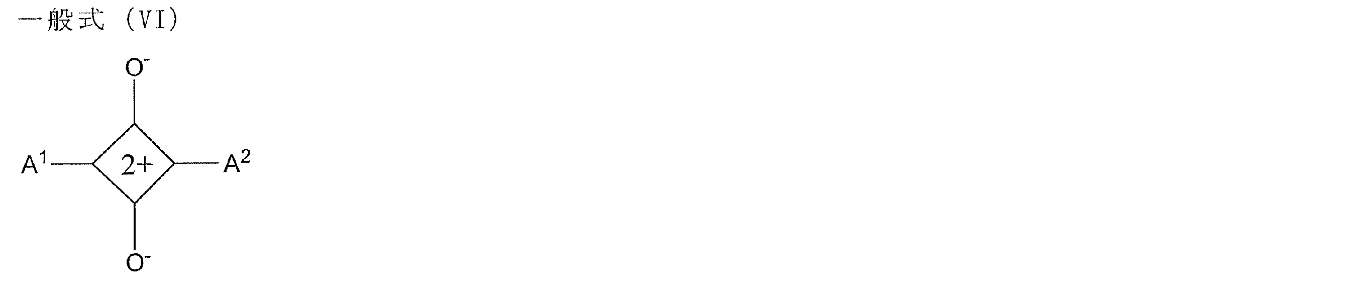
[9] 前記位相差層が、硬化性液晶性組成物を硬化してなることを特徴とする[1]~[8]のいずれかの印画紙。
[10] 前記位相差層が、パターン露光された光配向膜によって配向制御された硬化性液晶性組成物を硬化してなることを特徴とする[12]の印画紙。
[11] 前記直線偏光層と前記位相差層との間に、波長550nmにおける面内レターデーションRe(550)が、0~10nmである、前記直線偏光層の保護層をさらに有することを特徴とする[1]~[10]のいずれかの印画紙。
[12] 前記保護層及び前記位相差層の、波長550nmにおける厚み方向レターデーションRth(550)の合計の絶対値が、20nm以下であることを特徴とする[11]の印画紙。
[13] 前記光透過性画像受像層が、銀塩写真法により画像受像可能な画像受像層であり、青感光性乳剤層、緑感光性乳剤層、及び赤感光性乳剤層を有することを特徴とする[1]~[12]のいずれかの印画紙。
[14] 前記光透過性画像受像層が、感熱転写法により画像受像可能な画像受像層であり、染色性受容ポリマーの少なくとも1種を含有することを特徴とする[1]~[12]のいずれかの印画紙。
[15] 前記画像受像層が、インクジェット法により画像受像可能な画像受像層であり、水溶性高分子及び無機微粒子を少なくとも含む組成物からなることを特徴とする[1]~[12]のいずれかの印画紙。
[16] 前記位相差層と前記画像受像層との間の距離dが、500μm以下である[1]~[15]のいずれかの印画紙。
[17] 前記位相差層と前記画像受像層との間の距離dと、前記第1及び第2のドメインのパターン境界線の間隔pとの比(d/p)が、3以下である[1]~[16]のいずれかの印画紙。
[10] 前記位相差層が、パターン露光された光配向膜によって配向制御された硬化性液晶性組成物を硬化してなることを特徴とする[12]の印画紙。
[11] 前記直線偏光層と前記位相差層との間に、波長550nmにおける面内レターデーションRe(550)が、0~10nmである、前記直線偏光層の保護層をさらに有することを特徴とする[1]~[10]のいずれかの印画紙。
[12] 前記保護層及び前記位相差層の、波長550nmにおける厚み方向レターデーションRth(550)の合計の絶対値が、20nm以下であることを特徴とする[11]の印画紙。
[13] 前記光透過性画像受像層が、銀塩写真法により画像受像可能な画像受像層であり、青感光性乳剤層、緑感光性乳剤層、及び赤感光性乳剤層を有することを特徴とする[1]~[12]のいずれかの印画紙。
[14] 前記光透過性画像受像層が、感熱転写法により画像受像可能な画像受像層であり、染色性受容ポリマーの少なくとも1種を含有することを特徴とする[1]~[12]のいずれかの印画紙。
[15] 前記画像受像層が、インクジェット法により画像受像可能な画像受像層であり、水溶性高分子及び無機微粒子を少なくとも含む組成物からなることを特徴とする[1]~[12]のいずれかの印画紙。
[16] 前記位相差層と前記画像受像層との間の距離dが、500μm以下である[1]~[15]のいずれかの印画紙。
[17] 前記位相差層と前記画像受像層との間の距離dと、前記第1及び第2のドメインのパターン境界線の間隔pとの比(d/p)が、3以下である[1]~[16]のいずれかの印画紙。
[18] [1]~[17]のいずれかの印画紙と、該印画紙の光透過性画像受像層に形成された視差のある左眼用画像及び右眼用画像とを有する立体画像印刷物であって、該左眼用画像及び右眼用画像のそれぞれを構成する画素が、前記印画紙の位相差層の第1のドメイン及び第2のドメインに対応する位置に形成されていることを特徴とする立体画像印刷物。
[19] 観察者の視認側と反対の面に、非偏光解消性の反射層をさらに有することを特徴とする[18]の立体画像印刷物。
[20] [1]~[13]のいずれかの印画紙の光透過性画像受像層に、ライトジェット法により視差のある左眼用画像及び右眼用画像を、前記印画紙の位相差層の第1のドメイン及び第2のドメインに対応する位置にそれぞれ形成することを含む立体画像印刷物の製造方法。
[21] [1]~[12]及び[14]のいずれかの印画紙の光透過性画像受像層に、色素を含有する感熱転写シートを重ね合わせること、
電気信号によって発熱が制御されるサーマルヘッドによって該感熱転写シートを加熱して、視差のある左眼用画像及び右眼用画像を、前記印画紙の位相差層の第1のドメイン及び第2のドメインに対応する位置にそれぞれ、色素を転写することで形成すること;
を含む立体画像印刷物の製造方法。
[22] [1]~[12]及び[15]のいずれかの印画紙の光透過性画像受像層に、インクジェット法により、視差のある左眼用画像及び右眼用画像を、前記印画紙の位相差層の第1のドメイン及び第2のドメインに対応する位置にそれぞれ形成することを含む立体画像印刷物の製造方法。
[23] [18]又は[19]の立体画像印刷物を準備すること、
該立体画像印刷物を、左眼用及び右眼用のレンズが、互いに逆向きの円偏光レンズ、又は偏光軸が互いに直交した直線偏光レンズである、偏光メガネを着用した観察者に対して表示すること、
を含む立体画像の提供方法。
[19] 観察者の視認側と反対の面に、非偏光解消性の反射層をさらに有することを特徴とする[18]の立体画像印刷物。
[20] [1]~[13]のいずれかの印画紙の光透過性画像受像層に、ライトジェット法により視差のある左眼用画像及び右眼用画像を、前記印画紙の位相差層の第1のドメイン及び第2のドメインに対応する位置にそれぞれ形成することを含む立体画像印刷物の製造方法。
[21] [1]~[12]及び[14]のいずれかの印画紙の光透過性画像受像層に、色素を含有する感熱転写シートを重ね合わせること、
電気信号によって発熱が制御されるサーマルヘッドによって該感熱転写シートを加熱して、視差のある左眼用画像及び右眼用画像を、前記印画紙の位相差層の第1のドメイン及び第2のドメインに対応する位置にそれぞれ、色素を転写することで形成すること;
を含む立体画像印刷物の製造方法。
[22] [1]~[12]及び[15]のいずれかの印画紙の光透過性画像受像層に、インクジェット法により、視差のある左眼用画像及び右眼用画像を、前記印画紙の位相差層の第1のドメイン及び第2のドメインに対応する位置にそれぞれ形成することを含む立体画像印刷物の製造方法。
[23] [18]又は[19]の立体画像印刷物を準備すること、
該立体画像印刷物を、左眼用及び右眼用のレンズが、互いに逆向きの円偏光レンズ、又は偏光軸が互いに直交した直線偏光レンズである、偏光メガネを着用した観察者に対して表示すること、
を含む立体画像の提供方法。
本発明によれば、クロストークやゴースト像が低減された、立体画像印刷物を提供することができる。
以下、本発明について詳細に説明する。なお、本明細書において「~」を用いて表される数値範囲は、「~」の前後に記載される数値を下限値および上限値として含む範囲を意味する。
なお、本明細書では、Re(λ)は波長λnmにおける面内レターデーション値(単位:nm)、及びRth(λ)は波長λnmにおける膜厚方向のレターデーション値(単位:nm)である。また、波長が省略されている場合は、波長550nmの値をいうものとする。また、面内レターデーション(Re(λ))はKOBRA 21ADHまたはWR(王子計測機器(株)製)において波長λnmの光をフィルム法線方向に入射させて測定される。厚み方向レターデーション(Rth(λ))は、Re(λ)の値、及び斜め方向から入射して測定される複数の値に基づいて算出される値である。
また、本明細書では、「可視光」とは、380nm~780nmのことをいう。また、本明細書では、測定波長について特に付記がない場合は、測定波長は550nmである。
また、本明細書において、角度(例えば「90°」等の角度)、及びその関係(例えば「直交」、「平行」、及び「45°で交差」等)については、本発明が属する技術分野において許容される誤差の範囲を含むものとする。例えば、厳密な角度±10°未満の範囲内であることなどを意味し、厳密な角度との誤差は、5°以下であることが好ましく、3°以下であることがより好ましい。
なお、本明細書では、Re(λ)は波長λnmにおける面内レターデーション値(単位:nm)、及びRth(λ)は波長λnmにおける膜厚方向のレターデーション値(単位:nm)である。また、波長が省略されている場合は、波長550nmの値をいうものとする。また、面内レターデーション(Re(λ))はKOBRA 21ADHまたはWR(王子計測機器(株)製)において波長λnmの光をフィルム法線方向に入射させて測定される。厚み方向レターデーション(Rth(λ))は、Re(λ)の値、及び斜め方向から入射して測定される複数の値に基づいて算出される値である。
また、本明細書では、「可視光」とは、380nm~780nmのことをいう。また、本明細書では、測定波長について特に付記がない場合は、測定波長は550nmである。
また、本明細書において、角度(例えば「90°」等の角度)、及びその関係(例えば「直交」、「平行」、及び「45°で交差」等)については、本発明が属する技術分野において許容される誤差の範囲を含むものとする。例えば、厳密な角度±10°未満の範囲内であることなどを意味し、厳密な角度との誤差は、5°以下であることが好ましく、3°以下であることがより好ましい。
また、本明細書において、「パターニング」とは、フィルム状(層状)の対象物に、光軸(遅相軸を含む意味で用いる)の方向が互いに異なる領域を2つ以上作製すること、または、同領域を2つ以上有することを意味する。
また、本明細書では、「クロストーク」及び「ゴースト像」とは、左右画像の分離が不完全である場合に、二重像として認識されること、及び目的画像以外の像として認識されることをいう。
また、本明細書では、「クロストーク」及び「ゴースト像」とは、左右画像の分離が不完全である場合に、二重像として認識されること、及び目的画像以外の像として認識されることをいう。
1.立体画像印刷用印画紙
本発明は、光透過性画像受像層、直線偏光層、及び位相差層をこの順で有し、且つ前記位相差層が、面内遅相軸の方向又は面内レターデーションが互いに異なる第1及び第2のドメインにパターニングされたパターニング位相差層であることを特徴とする立体画像印刷用印画紙に関する。
本発明の印画紙は、光透過性画像受像層を備えているので、色濃度の高い視差のある左眼画像及び右眼画像を形成することができる。その結果、画像受像層を利用していない従来例と比較して、クロストーク及びゴースト像を軽減することができる。さらに、塗布手段等により形成された色素受像性の画像受像層を有する態様では、薄層化が可能であり、クロストーク及びゴースト像をより軽減することができる。さらに、感熱転写法、インクジェット法、又は銀塩写真法(特にライトジェット法)により画像受像可能な画像受像層を備えた態様では、サーマルヘッド、インクジェットヘッド、又は画像描き込みのためのレーザー光を制御することで、位相差層のパターンに対応した所望の位置に、色濃度の高い視差のある左眼画像及び右眼画像を容易に形成することができる。
本発明は、光透過性画像受像層、直線偏光層、及び位相差層をこの順で有し、且つ前記位相差層が、面内遅相軸の方向又は面内レターデーションが互いに異なる第1及び第2のドメインにパターニングされたパターニング位相差層であることを特徴とする立体画像印刷用印画紙に関する。
本発明の印画紙は、光透過性画像受像層を備えているので、色濃度の高い視差のある左眼画像及び右眼画像を形成することができる。その結果、画像受像層を利用していない従来例と比較して、クロストーク及びゴースト像を軽減することができる。さらに、塗布手段等により形成された色素受像性の画像受像層を有する態様では、薄層化が可能であり、クロストーク及びゴースト像をより軽減することができる。さらに、感熱転写法、インクジェット法、又は銀塩写真法(特にライトジェット法)により画像受像可能な画像受像層を備えた態様では、サーマルヘッド、インクジェットヘッド、又は画像描き込みのためのレーザー光を制御することで、位相差層のパターンに対応した所望の位置に、色濃度の高い視差のある左眼画像及び右眼画像を容易に形成することができる。
本発明の立体画像印刷用印画紙の第1の態様は、前記位相差層が、1/4波長層であって、第1及び第2のドメインの面内遅相軸が互いに90°をなすパターニング位相差層であって、第1のドメインの面内遅相軸及び第2のドメインの面内遅相軸のそれぞれが、前記直線偏光層の偏光軸と±45°の角度をなしている態様である。図1に本態様の立体画像印刷用印画紙の一例の断面模式図を示す。図1に示す印画紙10Aは、光透過性画像受像層12、直線偏光層14、及び1/4波長層16をこの順で有する。1/4波長層16は、それぞれの遅相軸が90°の角度をなす第1のドメイン16a及び第2のドメイン16bにパターニングされている。例えば、図2に示す通り、第1のドメイン16aの遅相軸aは-45°の方向、及び第2のドメイン16の遅相軸bは+45°の方向になっていて、互いに90°の角度をなしている。さらに、第1及び第2のドメイン16a、16bの遅相軸a及びbはそれぞれ、直線偏光層14の偏光軸と±45°の角度をなしている。例えば、図2に破線で示す通り、直線偏光層14の偏光軸は、0°の方向の偏光軸cであっても、90°の方向の偏光軸c’であっても上記関係を満足する。
なお、図2には、第1及び第2のドメイン16a及び16bがスプライト形状である態様を示したが、この態様に限定されるものではない。
なお、図2には、第1及び第2のドメイン16a及び16bがスプライト形状である態様を示したが、この態様に限定されるものではない。
光透過性画像受像層12に、種々の方法で画像が形成され、当該画像を1/4波長層16から観察すると、第1のドメイン16aに対応する位置の画像は、遅相軸aによって決定される向きの円偏光画像として観察者の眼に入射し、第2のドメイン16bに対応する位置の画像は、遅相軸bによって決定される向きの円偏光画像として観察者の眼に入射する。遅相軸a及びbが直交しているので、それぞれと対応して軸合わせされた偏光レンズを左右のレンズとして有する円偏光メガネを装着した観察者が観察すれば、第1及び第2のドメイン16a及び16bからの円偏光画像を、左眼及び右眼のいずれかにのみ入射させることができる。よって、光透過性画像受像層12の第1及び第2のドメイン16a、16bに対応する位置に、それぞれ視差のある左眼用及び右眼用の画像を構成する画素を印字することにより、当該画像を円偏光メガネを装着した観察者に表示すれば、立体画像として認識することができる。
本発明の立体画像印刷用印画紙の第2の態様は、前記位相差層の第1のドメインの面内レターデーションが0であり、第2のドメインの面内レターデーションが1/2波長であるパターニング位相差層であって、前記直線偏光層の偏光軸と第2のドメインの面内遅相軸とが45°の角度をなしている態様である。本態様の印画紙の一例の断面模式図を図3に示す。図3に示す印画紙20Aは、光透過性画像受像層22、直線偏光層24、及び位相差26をこの順で有する。位相差層26は、Reが0nmである第1のドメイン26a、及びReが1/2波長である第2のドメイン26bにパターニングされている。また、第2のドメイン26bの遅相軸bは、+45°の方向になっていて、直線偏光層24の偏光軸と45°の角度をなしている。例えば、図4に破線で示す通り、直線偏光層24の偏光軸は、0°の方向の偏光軸cであっても、90°の方向の偏光軸c’であっても上記関係を満足する。
光透過性画像受像層22に種々の方法で画像が形成され、当該画像を位相差層26から観察すると、第1のドメイン26aに対応する位置の画像は、直線偏光層24の偏光軸cの方向によって決定される直線偏光画像として観察者の眼に入射し、第2のドメイン26bに対応する位置の画像は、第2のドメイン26bの1/2波長のレターデーションによって、第1のドメイン26aに対応する位置の画像と偏光軸が直交する直線偏光画像として観察者の眼に入射する。それぞれと対応して軸合わせされた直線偏光レンズを左右のレンズとして有する偏光メガネを装着した観察者が観察すれば、第1及び第2のドメイン26a及び26bからの偏光画像を、左眼及び右眼のいずれかにのみ入射させることができる。よって、光透過性画像受像層22の第1及び第2のドメイン26a、26bに対応する位置に、それぞれ視差のある左眼用及び右眼用の画像を構成する画素を印字することにより、当該画像を偏光メガネを装着した観察者に表示すれば、立体画像として認識することができる。
本発明の立体画像用印画紙では、画像受像層に形成される左眼用及び右眼用の画像のパターン形状は位相差層の第1及び第2のドメインの形状とほぼ同一であることが好ましい。また、印画紙に形成される左眼用及び右眼用画像のパターンは、印画紙面内において同程度の面積を占めることが好ましい。また、それぞれの領域が印画紙面内の一部に偏ることなく、全体にわたって均等に分布していることが好ましい。人間の眼の解像度に対する感度は垂直方向に低く水平方向に高いため、水平方向の解像度が高くなるようなパターンが好ましい。また、奥行き知覚をもたらす両眼視差は、左右両眼のそれぞれの視野内における観察対象の位置の水平方向のずれに相当するため、水平方向の解像度が高いことは、奥行きのなめらかな立体視を与える点からも好ましい。
図1及び図3に示す態様では、スプライト形状である態様を示したが、この態様に限定されるものではない。パターン形状として具体的には、横ストライプ、斜めストライプ、縦ストライプ、チェッカーが挙げられ、好ましくは横ストライプ、斜めストライプ、チェッカーであり、よりこのましくは横ストライプ、ストライプの傾きが水平方向に対して45°以下の斜めストライプ、チェッカーであり、さらに好ましくは横ストライプ、ストライプの傾きが水平方向に対して30°以下の斜めストライプであり、よりさらに好ましくは横ストライプである。パターン境界線の間隔は、好ましくは10μm以上5mm以下であり、より好ましくは30μm以上2mm以下であり、さらに好ましくは50μm以上1mm以下であり、よりさらに好ましくは100μm以上500μm以下である。間隔が大き過ぎると、境界線間の領域が黒表示として認識される側の眼において、パターン形状が黒い模様として容易に視認されるようになり、画質を悪化させるため好ましくない。逆に間隔が小さ過ぎると、偏光子と印画紙のパターンのわずかなずれが大きなクロストークを発生させるため好ましくない。
図5~図12に、第1及び/又は第2の態様の印画紙の他の例の断面模式図を示す。なお、図1及び図3中と同一の部材については、同一の番号を付し、詳細な説明は省略する。
図5に示す印画紙10B(又は20B)は、直線偏光層14(又は24)を保護する保護層14a、14bを有する。直線偏光膜として一般的なポリビニルアルコール(PVA)フィルム等は、吸湿性が高く耐久性改善のために、高分子フィルムによってその両面を保護して用いられることが多い。図5に示す例では、直線偏光層14(又は24)は、高分子フィルムからなる保護層14a及び14bによって保護されている。但し、直線偏光層14(又は24)と1/4波長層16(又は位相差層26)との間に配置される保護層14bが、高位相差であると、第1及び第2のドメイン16a、16b(又は26a、26b)から観察者の眼に入射する円偏光画像の円偏光状態を変化させ、クロストーク及びゴースト像の原因になる。よって、保護層14bは、低位相差であるのが好ましく、具体的には、波長550nmにおける面内レターデーションRe(550)が、0~10nmであるのが好ましく、5nm以下であるのがより好ましい。
図5に示す印画紙10B(又は20B)は、直線偏光層14(又は24)を保護する保護層14a、14bを有する。直線偏光膜として一般的なポリビニルアルコール(PVA)フィルム等は、吸湿性が高く耐久性改善のために、高分子フィルムによってその両面を保護して用いられることが多い。図5に示す例では、直線偏光層14(又は24)は、高分子フィルムからなる保護層14a及び14bによって保護されている。但し、直線偏光層14(又は24)と1/4波長層16(又は位相差層26)との間に配置される保護層14bが、高位相差であると、第1及び第2のドメイン16a、16b(又は26a、26b)から観察者の眼に入射する円偏光画像の円偏光状態を変化させ、クロストーク及びゴースト像の原因になる。よって、保護層14bは、低位相差であるのが好ましく、具体的には、波長550nmにおける面内レターデーションRe(550)が、0~10nmであるのが好ましく、5nm以下であるのがより好ましい。
また、保護層14bのRthも円偏光画像の円偏光状態に影響を与え、クロストーク及びゴースト像の原因になるので、1/4波長層16と保護層14bのRthの合計の絶対値は、20nm以下であるのが好ましく、5nm以下であるのがより好ましい。
図6に、第1及び第2の態様の印画紙の他の例の断面模式図を示す。
図6に示す印画紙10C(又は20C)は、1/4波長層16(又は位相差層26)を硬化性液晶性組成物を硬化して形成した態様であり、より具体的には、その下に配置した配向膜からなる配向層15(又は25)によって、硬化性液晶性組成物の配向を制御し、該配向を固定して形成した1/4波長層16(又は位相差層26)を有する態様である。配向層15は、光照射によって配向規制力が発現し、光照射方向に応じて、配向軸が決定される光配向膜であっても、ラビング処理によって配向規制力が発現し、一般的には、ラビング処理方向に応じて、配向軸が決定されるラビング配向膜であってもよい。
図6に示す印画紙10C(又は20C)は、1/4波長層16(又は位相差層26)を硬化性液晶性組成物を硬化して形成した態様であり、より具体的には、その下に配置した配向膜からなる配向層15(又は25)によって、硬化性液晶性組成物の配向を制御し、該配向を固定して形成した1/4波長層16(又は位相差層26)を有する態様である。配向層15は、光照射によって配向規制力が発現し、光照射方向に応じて、配向軸が決定される光配向膜であっても、ラビング処理によって配向規制力が発現し、一般的には、ラビング処理方向に応じて、配向軸が決定されるラビング配向膜であってもよい。
印画紙10Cの配向層15に利用される光配向膜の一例は、パターン露光により、互いに90°の角度をなす配向軸を有する第1の光配向膜ドメイン及び第2の光配向膜ドメインからなる。
また、印画紙10Cの配向層15に利用されるラビング配向膜の一例は、マスクラビング処理により、互いに90°の角度をなす配向軸を有する第1のラビング配向膜ドメイン及び第2のラビング配向膜ドメインからなるラビング配向膜である。
また、印画紙10Cの配向層15に利用されるラビング配向膜の一例は、マスクラビング処理により、互いに90°の角度をなす配向軸を有する第1のラビング配向膜ドメイン及び第2のラビング配向膜ドメインからなるラビング配向膜である。
また、ラビング配向膜の中には、温度変化を与えると、配向規制力が変化又は消失するものもある。かかるラビング配向膜を配向層15(又は25)として利用しても勿論よい。具体的には、一方向にラビング処理されたラビング配向膜からなる配向層15であって、温度変化により配向規制力が変化するラビング配向膜を、互いに直交する面内遅相軸を有する第1のドメイン及び第2のドメインを含む1/4波長層16の形成に利用することができる。温度変化による配向規制力の変化は、例えば、配向膜材料、液晶、及び配向制御剤のいずれか2以上の材料間の親和性を変化させることにより達成でき、ラビング方向に対して液晶の遅相軸が直交配向した配向状態、及びラビング方向に対して液晶の遅相軸が平行配向した配向状態を、それぞれ実現することができる。温度T1℃で、直交配向状態とした後に、フォトマスク下の紫外線照射により、当該配向状態を所定のパターンで固定した後、温度T2(但し、T1<T2)℃で、非照射領域を平行配向状態とする。さらに紫外線照射によりその状態を固定することで、面内遅相軸が互いに直交する第1及び第2のドメインを有するパターニング1/4波長層を形成することができる。この例の詳細は後述する。
印画紙10Cの配向層15に利用可能な一方向にラビング処理されたラビング配向膜の他の例としては、組成が互いに異なり、且つ互いに異なる配向制御能を示す配向制御表面を有する、第一の配向制御領域及び第二の配向制御領域を含んでおり、それぞれの配向制御表面が交互に配置されたパターニング配向制御層であり、前記第一の配向制御領域及び前記第二の配向制御領域のそれぞれの配向制御面が、該配向制御面に平行な面内において液晶の長軸を互いに直交する方向に配向制御可能であるラビング配向膜である。この例についても詳細は後述する。
印画紙20Cの配向層25の例としては、一方向にラビング処理されたラビング配向膜であって、温度変化を与えることにより配向規制力を消失する配向膜が挙げられる。温度T1℃で、直交又は水平配向状態とした後に、フォトマスク下の紫外線照射により、当該配向状態を所定のパターンで固定した後、温度T3(但し、T1<T3)℃で、非照射領域を等方性相状態にする。さらに紫外線照射によりその状態を固定することで、Reが1/2波長である第2のドメイン26bにパターニングされている位相差層を形成することができる。
図7に第1及び第2の態様の印画紙の他の例の断面模式図を示す。図7に示す印画紙10D(又は20D)は、直線偏光層14(又は24)の保護層14aの表面と、画像受像層12(又は22)とを位置合わせした後、粘着剤で貼り合せた態様であり、保護層14aと画像受像層12(又は22)との間に粘着剤層17を有する態様である。
図8に第1及び第2の態様の印画紙の他の例の断面模式図を示す。図8に示す印画紙10E(又は20E)は、透明支持体18上に、配向層15(又は25)を形成し、当該配向層15(又は25)の配向制御能を利用してパターニング1/4波長層16(又は位相差層26)を形成し、積層体を作製し、該積層体のパターニング1/4波長層16(又は位相差層26)の表面を、直線偏光層14(又は24)の保護層14bと粘着剤で貼り合せた態様である。保護層14bとパターニング1/4波長層16(又は位相差層26)との間、及び保護層14aと画像受像層12(又は22)との間に粘着剤層17を有する態様である。
なお、本態様に用いる透明支持体18は、後述する直線偏光層の保護層14a、14bに利用可能な部材と同様であり、その好ましい範囲も同一である。
なお、本態様に用いる透明支持体18は、後述する直線偏光層の保護層14a、14bに利用可能な部材と同様であり、その好ましい範囲も同一である。
図9に第1及び第2の態様の印画紙の他の例の断面模式図を示す。図9に示す印画紙10F(又は20F)は、透明支持体18上に、配向層15(又は25)を形成し、当該配向層15(又は25)の配向制御能を利用してパターニング1/4波長層16(又は位相差層26)を形成し、積層体を作製し、該積層体のパターニング1/4波長層16(又は位相差層26)の表面を、直接、直線偏光層14の表面と粘着剤で貼り合せた態様である。直線偏光層14(又は24)とパターニング1/4波長層16(又は位相差層26)との間に粘着剤層17を有する。本態様は、後述するように、パターニング1/4波長層16(又は位相差層26)と、画像受像層12の積層距離が短いので、クロストークがより軽減されるという効果がある。
図10に第1及び第2の態様の印画紙の他の例の断面模式図を示す。図10に示す印画紙10G(又は20G)は、いずれの表面にも保護層を有さず、直線偏光層14(又は24)の表面を、画像受像層12の表面と粘着剤で貼り合せた態様である。本態様では、さらにパターニング1/4波長層16(又は位相差層26)と画像受像層12の積層距離が短くなるため、クロストークがより軽減される。
図11に第1及び第2の態様の印画紙の他の例の断面模式図を示す。図11に示す印画紙10H(又は20H)は、直線偏光層14(又は24)の表面に、塗布手段等により、画像受像層12(又は22)を直接形成した態様である。
図12に第1及び第2の態様の印画紙の他の例の断面模式図を示す。図12に示す印画紙10I(又は20I)は、パターニング1/4波長層16(又は位相差層26)の表面に、配向層15’を形成し、配向層15’の表面に、二色性色素を含有する液晶組成物等の偏光材料を塗布等により適用し、配向層15’の配向制御能により形成された塗布型の偏光層14’(又は24’)を有する態様である。配向層15’は、光照射によって配向規制力が発現し、光照射方向に応じて、配向軸が決定される光配向膜であっても、ラビング処理によって配向規制力が発現し、一般的には、ラビング処理方向に応じて、配向軸が決定されるラビング配向膜であってもよい。
図6~図12に示す印画紙10C~10I又は20C~20Iは、配向層15の配向規制力を利用して、第1のドメイン16a及び第2のドメイン16bからなる1/4波長層16、又は第1のドメイン26a及び第2のドメイン26bからなる位相差層26をそれぞれ形成するため、配向膜を利用している。1/4波長層16を形成するための光配向膜15の作製方法の一例は、以下の通りである。
まず、光配向膜用組成物を、直線偏光層14の表面に塗布して、膜を形成する。次に、ワイヤーグリッドを利用して直線偏光を照射する。具体的には、まず、図13(a)に示す様に、直線偏光層14の偏光軸cと45度をなす方向1に、ワイヤーグリッド偏光子をセットし、マスクA(図中、黒色部が遮光部で、且つ白色部が光透過部である。マスクBについても同様である)を介して露光する。その後、図13(b)に示す様に、直線偏光層14の偏光軸cと45度をなす方向2に、ワイヤーグリッド偏光子をセットし、マスクBを介して露光する。これにより、配向軸がそれぞれ±45°の方向にあり、互いに直交する、第1及び第2の光配向膜ドメインを形成することができる。さらに、この光配向膜上で硬化性液晶性組成物を配向させると、第1の光配向膜ドメイン上の液晶はその配向軸に従って配向し、及び第2の光配向膜ドメイン上の液晶はその配向軸に従って配向する。硬化反応を進行させて、それぞれの状態を固定すると、図2に示すような、遅相軸a及びbが互いに90°の方向をなし、且つ直線偏光層14の偏光軸cとそれぞれ±45°をなす第1及び第2のドメイン16a及び16bからなる1/4波長層16を形成することができる。
まず、光配向膜用組成物を、直線偏光層14の表面に塗布して、膜を形成する。次に、ワイヤーグリッドを利用して直線偏光を照射する。具体的には、まず、図13(a)に示す様に、直線偏光層14の偏光軸cと45度をなす方向1に、ワイヤーグリッド偏光子をセットし、マスクA(図中、黒色部が遮光部で、且つ白色部が光透過部である。マスクBについても同様である)を介して露光する。その後、図13(b)に示す様に、直線偏光層14の偏光軸cと45度をなす方向2に、ワイヤーグリッド偏光子をセットし、マスクBを介して露光する。これにより、配向軸がそれぞれ±45°の方向にあり、互いに直交する、第1及び第2の光配向膜ドメインを形成することができる。さらに、この光配向膜上で硬化性液晶性組成物を配向させると、第1の光配向膜ドメイン上の液晶はその配向軸に従って配向し、及び第2の光配向膜ドメイン上の液晶はその配向軸に従って配向する。硬化反応を進行させて、それぞれの状態を固定すると、図2に示すような、遅相軸a及びbが互いに90°の方向をなし、且つ直線偏光層14の偏光軸cとそれぞれ±45°をなす第1及び第2のドメイン16a及び16bからなる1/4波長層16を形成することができる。
光配向膜を利用して1/4波長層を形成した本態様の印画紙は、位置合わせ等の制御が比較的容易なパターン露光により、互いの遅相軸が90°をなし直線偏光層の偏光軸とそれぞれ±45°をなす1/4波長層を有するので、軸ズレ(例えば、1/4波長層の遅相軸間の軸ズレ、及び該遅相軸と直線偏光層の偏光軸との軸ズレ)が軽減されていて、本態様の印画紙上に形成された立体画像は、クロストーク及びゴースト像がより軽減されている。
なお、本発明の印画紙は、全ての層が固定されている必要はなく、取り外し可能に構成されていてもよい。例えば、光透過性画像受像層又はそれを含む積層体を、印画紙の他の構成部材から一旦取り外して、ライトジェット法等による画像形成、及び現像により立体画像を形成した後に、再び、他の部材と組み合わせて、所定の積層順に積層してもよい。
以下、本発明の印画紙を構成する各部材について、それぞれ詳細に説明する。
光透過性画像受像層:
本発明に係る画像受像層は、光透過性である。具体的には、光透過率が70%以上であるのが好ましく、80%以上であるのがより好ましく、90%以上であるのが特に好ましい。本発明では、塗布手段、吹き付け手段及び滴下手段のいずれかにより形成された色素受像性の画像受像層であるのが、より高い色濃度の画像を形成でき、クロストーク及びゴーストの発生をより軽減できるので好ましい。なお、本明細書において、「画像受像層」とは色素等からなる画像を受像可能な画像受像性の層であって、リバーサルのように、赤、緑、青の感光乳剤を受容し、ライトジェット法等により画像を形成する層、又は、感熱転写のように転写する色素を受容する層やインクジェット法のように打滴された色素を受容することにより画像を形成する層を意味するものとする。本発明では、画像受像層として、銀塩写真法(特にライトジェット法)、感熱転写法、又はインクジェット法により画像受像可能な画像受像層を利用するのが好ましい。それぞれ、画像描き込みのためのレーザー光、サーマルヘッド、又はインクジェットヘッドを制御することで、位相差層のパターンに対応した所望の位置に、色濃度の高い視差のある左眼画像及び右眼画像を容易に形成することができる。
光透過性画像受像層:
本発明に係る画像受像層は、光透過性である。具体的には、光透過率が70%以上であるのが好ましく、80%以上であるのがより好ましく、90%以上であるのが特に好ましい。本発明では、塗布手段、吹き付け手段及び滴下手段のいずれかにより形成された色素受像性の画像受像層であるのが、より高い色濃度の画像を形成でき、クロストーク及びゴーストの発生をより軽減できるので好ましい。なお、本明細書において、「画像受像層」とは色素等からなる画像を受像可能な画像受像性の層であって、リバーサルのように、赤、緑、青の感光乳剤を受容し、ライトジェット法等により画像を形成する層、又は、感熱転写のように転写する色素を受容する層やインクジェット法のように打滴された色素を受容することにより画像を形成する層を意味するものとする。本発明では、画像受像層として、銀塩写真法(特にライトジェット法)、感熱転写法、又はインクジェット法により画像受像可能な画像受像層を利用するのが好ましい。それぞれ、画像描き込みのためのレーザー光、サーマルヘッド、又はインクジェットヘッドを制御することで、位相差層のパターンに対応した所望の位置に、色濃度の高い視差のある左眼画像及び右眼画像を容易に形成することができる。
[銀塩写真により画像受像可能な画像受像層]
本発明では、銀塩写真法により画像受像可能な画像受像層を利用するのが好ましい。特に好ましくはライトジェット法により画像受像可能なリバーサルフィルムを利用するのが好ましい。リバーサルフィルムを用いると、レーザー光等を制御して、デジタル化された画像データに基づいて、位相差層の第1及び第2のドメインに相当する正確な位置に、左眼用及び右眼用画像をそれぞれ高い画像濃度で形成することができ、クロストーク及びゴースト像を軽減できる。後述するインクジェット法又は感熱転写法により画像受像可能な画像受像層を利用しても、クロストーク及びゴースト像の軽減に寄与するが、リバーサルフィルムを用いると、クロストーク及びゴースト像の軽減効果に加えて、予期せぬことに、立体画像の奥行き感をさらに改善できることがわかった。これは人間の目は水平方向の解像度に敏感に反応するためであると考えられる。銀塩写真により画像受像可能な画像受像層上にライトジェット法等でレーザー光により描き込みし、現像した画像は、インクジェット方式及び感熱転写方式で書き込まれた画像と比較して、網点階調に関して、粒状感のない連続階調が得られる。立体画像は横方向(水平方向)の解像度が高ければ高いほど、滑らかな奥行き感のある高階調な画像となるので、銀塩写真により画像受像可能な画像受像層を利用している本態様では、より奥行き感のある立体画像が得られたものと考えられる。
本発明では、銀塩写真法により画像受像可能な画像受像層を利用するのが好ましい。特に好ましくはライトジェット法により画像受像可能なリバーサルフィルムを利用するのが好ましい。リバーサルフィルムを用いると、レーザー光等を制御して、デジタル化された画像データに基づいて、位相差層の第1及び第2のドメインに相当する正確な位置に、左眼用及び右眼用画像をそれぞれ高い画像濃度で形成することができ、クロストーク及びゴースト像を軽減できる。後述するインクジェット法又は感熱転写法により画像受像可能な画像受像層を利用しても、クロストーク及びゴースト像の軽減に寄与するが、リバーサルフィルムを用いると、クロストーク及びゴースト像の軽減効果に加えて、予期せぬことに、立体画像の奥行き感をさらに改善できることがわかった。これは人間の目は水平方向の解像度に敏感に反応するためであると考えられる。銀塩写真により画像受像可能な画像受像層上にライトジェット法等でレーザー光により描き込みし、現像した画像は、インクジェット方式及び感熱転写方式で書き込まれた画像と比較して、網点階調に関して、粒状感のない連続階調が得られる。立体画像は横方向(水平方向)の解像度が高ければ高いほど、滑らかな奥行き感のある高階調な画像となるので、銀塩写真により画像受像可能な画像受像層を利用している本態様では、より奥行き感のある立体画像が得られたものと考えられる。
本態様において利用可能な銀塩写真により画像受像可能な画像受像層は、リバーサルフィルムであることが好ましい。種々のリバーサルフィルムから選択することができる。中でも、デジタルデータに基づく描画が可能な、ライトジェット描き込み可能なリバーサルフィルムが好ましい。使用するリバーサルフィルムは、OD(光学濃度)が高いものが好ましく、具体的には3以上が好ましい。インクジェット用及び感熱転写用の印画紙のODは、1.2程度であり、それらのODより高いほうが好ましい。
本態様に利用可能な銀塩写真により画像受像可能な画像受像層の一例は、ライトジェット法によるレーザー描き込みが可能なリバーサルフィルムであって、光透過性支持体上に、青感光性乳剤層、緑感光性乳剤層、及び赤感光性乳剤層を有するフルカラー用ハロゲン化銀カラーリバーサルフィルムである。この例については、特開平10-232470号公報及び特開2002-40604号公報等に詳細な記載があり、本発明に利用することができる。また、市販品を利用してもよく、例えば、フジクローム Velvia 50 プロフェッショナルRVP50、フジクローム T64 プロフェッショナル、フジクロームPROVIA 100F プロフェッショナル、フジクロームPROVIA 400X プロフェッショナル、フジクロームASTIA 100F プロフェッショナル、フジクロームSensiaIII 100、フジクローム Velvia 100F プロフェッショナル、フジクローム Velvia 100 プロフェッショナル、フジクローム TREBI 100C等を用いることもできる。
[感熱転写画像受像層]
本発明に利用可能な熱転写法により画像受像可能な画像受像層(感熱転写画像受像層)については特に制限はない。種々の感熱転写画像受像層を種々利用することができる。感熱転写時に、転写インクシートから移行してくる色素を受容し、形成された画像を維持するために染着しやすい樹脂(染着性受容ポリマー)を主成分として含有しているのが好ましい。感熱転写画像受像層の材料の例には、ポリエステル樹脂、ポリカーボネート樹脂、塩化ビニル樹脂、セルロース樹脂等が含まれる。また、以下の一般式[1]で表される繰り返し単位を有するポリマーを含有する感熱転写画像受像層は、転写感度及び画像保存性に優れているので好ましい。該ポリマーは、ラテックスとして含有されていてもよい。
本発明に利用可能な熱転写法により画像受像可能な画像受像層(感熱転写画像受像層)については特に制限はない。種々の感熱転写画像受像層を種々利用することができる。感熱転写時に、転写インクシートから移行してくる色素を受容し、形成された画像を維持するために染着しやすい樹脂(染着性受容ポリマー)を主成分として含有しているのが好ましい。感熱転写画像受像層の材料の例には、ポリエステル樹脂、ポリカーボネート樹脂、塩化ビニル樹脂、セルロース樹脂等が含まれる。また、以下の一般式[1]で表される繰り返し単位を有するポリマーを含有する感熱転写画像受像層は、転写感度及び画像保存性に優れているので好ましい。該ポリマーは、ラテックスとして含有されていてもよい。

一般式[1]において、R1は水素原子、ハロゲン原子またはメチル基を表し、L1は2価の連結基を表し、R2は炭素数1~5のアルキレン基を表す。nは1~40の整数を表す。Z1は水素原子、または炭素数1~30の直鎖、分岐もしくは環状の脂肪族炭化水素基を表す。ここで、R2におけるアルキレン基、Z1における脂肪族炭化水素基は置換基を有してもよく、nが2以上のとき、複数のR2は互いに同じでも異なってもよい。
R1がハロゲン原子を表す場合、好ましくは塩素原子又はフッ素原子である。
L1における2価の連結基は、どのような連結基でも構わないが、好ましくは、単結合、-O-、-C(=O)-、-NR11-〔ここで、R11は水素原子、アルキル基、シクロアルキル基、アリール基、またはアラルキル基を表す。〕、-S-、-SO2-、-P(=O)(OR12)-〔ここで、R12はアルキル基、シクロアルキル基、アリール基、またはアラルキル基を表す。〕、アルキレン基、アリーレン基、またはこれらの2つ以上を組み合わせて形成される2価の連結基が好ましく、-C(=O)-X-で表される基または置換基を有してもよいフェニレン基がより好ましく、-C(=O)-X-で表される基がさらに好ましい。ここで、Xは酸素原子、イオウ原子または-N(R0)-を表し、R0は、水素原子または置換基(該置換基として好ましくは、アルキル基、シクロアルキル基、アリール基、又はヘテロ環基であり、さらに好ましくは後述するRcである)を表す。L1は、-C(=O)-O-が最も好ましい。
R2のアルキレン基は鎖状でも分岐でもよいが、好ましくは鎖状である。また、炭素数は2~4が好ましい。
nは1~30の整数が好ましく、1~20の整数がより好ましく、1~10の整数が最も好ましい。
nは1~30の整数が好ましく、1~20の整数がより好ましく、1~10の整数が最も好ましい。
Z1における脂肪族炭化水素基としては、アルキル基、アルケニル基、アルキニル基、シクロアルキル基、シクロアルケニル基およびシクロアルキニル基が挙げられるが、アルキル基、アルケニル基、シクロアルキル基およびシクロアルケニル基が好ましく、アルキル基、シクロアルキル基がより好ましく、アルキル基がさらに好ましい。
アルケニル基およびアルキニル基は炭素数2~30(好ましくは2~20)、シクロアルキル基は炭素数3~30(好ましくは5~20)、シクロアルキニル基は炭素数6~30(好ましくは6~20)がそれぞれ好ましい。一方、アルキル基は炭素数1~20がより好ましい。
Z1は水素原子または上記の好ましい範囲の脂肪族基が好ましく、水素原子およびアルキル基がより好ましい。
アルケニル基およびアルキニル基は炭素数2~30(好ましくは2~20)、シクロアルキル基は炭素数3~30(好ましくは5~20)、シクロアルキニル基は炭素数6~30(好ましくは6~20)がそれぞれ好ましい。一方、アルキル基は炭素数1~20がより好ましい。
Z1は水素原子または上記の好ましい範囲の脂肪族基が好ましく、水素原子およびアルキル基がより好ましい。
ここで、本発明において、上記一般式[1]をも含め、各一般式で使用する、置換基もしくは「置換基を有していてもよい」における置換基に関して説明する。
本発明において、置換基とはどのようなものでも構わないが、下記の置換基群から選ばれる置換基が好ましい。
(置換基群)
アルキル基(好ましくは炭素数1~20、より好ましくは炭素数1~12、特に好ましくは炭素数1~8のアルキル基であり、例えば、メチル基、エチル基、イソプロピル基、tert-ブチル基、n-オクチル基、n-デシル基、n-ヘキサデシル基、シクロプロピル基、シクロペンチル基、シクロヘキシル基などが挙げられる)、アルケニル基(好ましくは炭素数2~20、より好ましくは炭素数2~12、特に好ましくは炭素数2~8のアルケニル基であり、例えば、ビニル基、アリール基、2-ブテニル基、3-ペンテニル基などが挙げられる)、アルキニル基(好ましくは炭素数2~20、より好ましくは炭素数2~12、特に好ましくは炭素数2~8のアルキニル基であり、例えば、プロパルギル基、3-ペンチニル基などが挙げられる)、アリール基(好ましくは炭素数6~30、より好ましくは炭素数6~20、特に好ましくは炭素数6~12のアリール基であり、例えば、フェニル基、p-メチルフェニル基、ナフチル基などが挙げられる)、置換もしくは無置換のアミノ基(好ましくは炭素数0~20、より好ましくは炭素数0~10、特に好ましくは炭素数0~6のアミノ基であり、例えば、無置換アミノ基、メチルアミノ基、ジメチルアミノ基、ジエチルアミノ基、アニリノ基などが挙げられる)、
本発明において、置換基とはどのようなものでも構わないが、下記の置換基群から選ばれる置換基が好ましい。
(置換基群)
アルキル基(好ましくは炭素数1~20、より好ましくは炭素数1~12、特に好ましくは炭素数1~8のアルキル基であり、例えば、メチル基、エチル基、イソプロピル基、tert-ブチル基、n-オクチル基、n-デシル基、n-ヘキサデシル基、シクロプロピル基、シクロペンチル基、シクロヘキシル基などが挙げられる)、アルケニル基(好ましくは炭素数2~20、より好ましくは炭素数2~12、特に好ましくは炭素数2~8のアルケニル基であり、例えば、ビニル基、アリール基、2-ブテニル基、3-ペンテニル基などが挙げられる)、アルキニル基(好ましくは炭素数2~20、より好ましくは炭素数2~12、特に好ましくは炭素数2~8のアルキニル基であり、例えば、プロパルギル基、3-ペンチニル基などが挙げられる)、アリール基(好ましくは炭素数6~30、より好ましくは炭素数6~20、特に好ましくは炭素数6~12のアリール基であり、例えば、フェニル基、p-メチルフェニル基、ナフチル基などが挙げられる)、置換もしくは無置換のアミノ基(好ましくは炭素数0~20、より好ましくは炭素数0~10、特に好ましくは炭素数0~6のアミノ基であり、例えば、無置換アミノ基、メチルアミノ基、ジメチルアミノ基、ジエチルアミノ基、アニリノ基などが挙げられる)、
アルコキシ基(好ましくは炭素数1~20、より好ましくは炭素数1~16、特に好ましくは炭素数1~10のアルコキシ基であり、例えば、メトキシ基、エトキシ基、ブトキシ基などが挙げられる)、アルコキシカルボニル基(好ましくは炭素数2~20、より好ましくは炭素数2~16、特に好ましくは2~10のアルコキシカルボニル基であり、例えば、メトキシカルボニル基、エトキシカルボニル基などが挙げられる)、アシルオキシ基(好ましくは炭素数2~20、より好ましくは炭素数2~16、特に好ましくは2~10のアシルオキシ基であり、例えば、アセトキシ基、ベンゾイルオキシ基などが挙げられる)、アシルアミノ基(好ましくは炭素数2~20、より好ましくは炭素数2~16、特に好ましくは炭素数2~10のアシルアミノ基であり、例えばアセチルアミノ基、ベンゾイルアミノ基などが挙げられる)、アルコキシカルボニルアミノ基(好ましくは炭素数2~20、より好ましくは炭素数2~16、特に好ましくは炭素数2~12のアルコキシカルボニルアミノ基であり、例えば、メトキシカルボニルアミノ基などが挙げられる)、アリールオキシカルボニルアミノ基(好ましくは炭素数7~20、より好ましくは炭素数7~16、特に好ましくは炭素数7~12のアリールオキシカルボニルアミノ基であり、例えば、フェニルオキシカルボニルアミノ基などが挙げられる)、スルホニルアミノ基(好ましくは炭素数1~20、より好ましくは炭素数1~16、特に好ましくは炭素数1~12のスルホニルアミノ基であり、例えば、メタンスルホニルアミノ基、ベンゼンスルホニルアミノ基などが挙げられる)、スルファモイル基(好ましくは炭素数0~20、より好ましくは炭素数0~16、特に好ましくは炭素数0~12のスルファモイル基であり、例えば、スルファモイル基、メチルスルファモイル基、ジメチルスルファモイル基、フェニルスルファモイル基などが挙げられる)、カルバモイル基(好ましくは炭素数1~20、より好ましくは炭素数1~16、特に好ましくは炭素数1~12のカルバモイル基であり、例えば、無置換のカルバモイル基、メチルカルバモイル基、ジエチルカルバモイル基、フェニルカルバモイル基などが挙げられる)、
アルキルチオ基(好ましくは炭素数1~20、より好ましくは炭素数1~16、特に好ましくは炭素数1~12のアルキルチオ基であり、例えば、メチルチオ基、エチルチオ基などが挙げられる)、アリールチオ基(好ましくは炭素数6~20、より好ましくは炭素数6~16、特に好ましくは炭素数6~12のアリールチオ基であり、例えば、フェニルチオ基などが挙げられる)、スルホニル基(好ましくは炭素数1~20、より好ましくは炭素数1~16、特に好ましくは炭素数1~12のスルホニル基であり、例えば、メシル基、トシル基などが挙げられる)、スルフィニル基(好ましくは炭素数1~20、より好ましくは炭素数1~16、特に好ましくは炭素数1~12のスルフィニル基であり、例えば、メタンスルフィニル基、ベンゼンスルフィニル基などが挙げられる)、ウレイド基(好ましくは炭素数1~20、より好ましくは炭素数1~16、特に好ましくは炭素数1~12のウレイド基であり、例えば、無置換のウレイド基、メチルウレイド基、フェニルウレイド基などが挙げられる)、リン酸アミド基(好ましくは炭素数1~20、より好ましくは炭素数1~16、特に好ましくは炭素数1~12のリン酸アミド基であり、例えば、ジエチルリン酸アミド基、フェニルリン酸アミド基などが挙げられる)、ヒドロキシ基、メルカプト基、ハロゲン原子(例えばフッ素原子、塩素原子、臭素原子、ヨウ素原子)、シアノ基、スルホ基、カルボキシル基、ニトロ基、ヒドロキサム酸基、スルフィノ基、ヒドラジノ基、イミノ基、ヘテロ環基(好ましくは炭素数1~30、より好ましくは1~12のヘテロ環基であり、例えば、窒素原子、酸素原子、硫黄原子等のヘテロ原子を有するヘテロ環基であり、例えば、イミダゾリル基、ピリジル基、キノリル基、フリル基、ピペリジル基、モルホリノ基、ベンゾオキサゾリル基、ベンズイミダゾリル基、ベンズチアゾリル基などが挙げられる)、シリル基(好ましくは、炭素数3~40、より好ましくは炭素数3~30、特に好ましくは、炭素数3~24のシリル基であり、例えば、トリメチルシリル基、トリフェニルシリル基などが挙げられる)が含まれる。
これらの置換基はさらにこれらの置換基によって置換されていてもよい。また、置換基を二つ以上有する場合は、同じでも異なってもよい。また、可能な場合には互いに結合して環を形成していてもよい。
これらの置換基はさらにこれらの置換基によって置換されていてもよい。また、置換基を二つ以上有する場合は、同じでも異なってもよい。また、可能な場合には互いに結合して環を形成していてもよい。
前記一般式[1]で表されるモノマーは、下記一般式[2]で表されるモノマーであることが好ましい。

一般式[2]において、R3は水素原子、ハロゲン原子またはメチル基を表し、Xは酸素原子、イオウ原子または-N(Rc)-を表す。ここで、Rcは水素原子、または置換基を有していてもよい炭素数1~8のアルキル基もしくはシクロアルキル基を表す。R4は炭素数1~5のアルキレン基を表す。mは1~40の整数を表す。Z2は水素原子、または炭素数1~30の直鎖、分岐もしくは環状の脂肪族炭化水素基を表す。ここで、Rcにおけるアルキル基、シクロアルキル基、R4におけるアルキレン基、Z2における脂肪族炭化水素基は置換基を有してもよく、mが2以上のとき、複数のR4は互いに同じでも異なってもよい。
R3、R4、mおよびZ2は、それぞれ対応する一般式[1]のR1、R2、nおよびZ1と同義であり、好ましい範囲も同じである。
R3、R4、mおよびZ2は、それぞれ対応する一般式[1]のR1、R2、nおよびZ1と同義であり、好ましい範囲も同じである。
Xは、酸素原子が好ましい。Rcで表されるアルキル基は炭素数3~8が好ましく、Rcで表されるシクロアルキル基は炭素数3~8が好ましい。
前記一般式[1]又は[2]で表されるモノマーは、下記一般式[3]で表されるモノマーであることがより好ましい。

一般式[3]において、R5は水素原子、ハロゲン原子またはメチル基を表し、R6は炭素数2~4のアルキレン基を表す。lは1~40の整数を表す。Z3は水素原子、または炭素数1~20の直鎖、分岐もしくは環状の脂肪族炭化水素基を表す。ここで、R6におけるアルキレン基、Z3における脂肪族炭化水素基は置換基を有してもよく、lが2以上のとき、複数のR4は互いに同じでも異なってもよい。
R5、R6およびlは、それぞれ対応する一般式[1]のR1、R2およびnと同義であり、好ましい範囲も同じである。Z3は一般式[1]におけるZ1における包含される範囲において、好ましい範囲と同じである。
R5、R6およびlは、それぞれ対応する一般式[1]のR1、R2およびnと同義であり、好ましい範囲も同じである。Z3は一般式[1]におけるZ1における包含される範囲において、好ましい範囲と同じである。
前記一般式[1]~[3]で表されるモノマーの好ましい例には、特開2008-105397号公報の[0035]~[0037]、及び特開2008-105398号公報の[0030]~[0033]に記載の化合物が含まれる。
また、前記一般式[1]~[3]で表されるモノマーは、日本油脂製ブレンマーシリーズ、及び東亜合成製アロニックスシリーズとして市販されているので、当該市販品を用いることもできる。
また、前記一般式[1]~[3]で表されるモノマーは、日本油脂製ブレンマーシリーズ、及び東亜合成製アロニックスシリーズとして市販されているので、当該市販品を用いることもできる。
前記一般式[1]~[3]で表されるモノマーから誘導される繰り返し単位を有するポリマーは、他のモノマーとの共重合体であってもよい。他のモノマーの例には、特開2008-105397号公報の[0039]~[0042]に記載のモノマーの例が含まれ、好ましい例も同様である。また前記ポリマーの具体例には、同公報の[0043]~[0047]に記載のポリマーが含まれる。また、上記した通り、前記ポリマーは、ポリマーラテックスとして前記感熱転写画像受像層中に含有されていてもよく、該ポリマーラテックスも、前記一般式[1]~[3]で表されるモノマーと、他のモノマーとの共重合体であるのが好ましい。前記ポリマーラテックスを構成する他のモノマーの例には、特開2008-105398号公報の[0035]~[0048]に記載の他のモノマーが含まれ、好ましい例も同様である。また、前記ポリマーラテックスの好ましい例には、同公報の[0053]~[0057]に記載の共重合体が含まれ、ポリマーラテックスの詳細については、同公報の[0049]~[0051]に記載の態様と同様である。
前記画像受像層は、前記一般式[1]で表されるモノマーの繰り返し単位を含むポリマー及びポリマーラテックスとともに、他のポリマー及び/又は他のポリマーラテックスの少なくとも1種を含有していてもよい。併用可能な他のポリマー及び/又は他のポリマーラテックスの例には、特開2008-105397号公報の[0049]~[0074]、並びに特開2008-105398号公報の[0059]~[0075]に記載の例が含まれる。
前記画像受像層は、前記一般式[1]で表されるモノマーの繰り返し単位を含むポリマー等の主成分ポリマーを含む塗布組成物を、表面に塗布し、乾燥することで形成することができる。前記塗布組成物の調製には有機溶媒(例えば、メチルエチルケトン及びトルエン)を用いることができ、また可能であれば水及び有機溶媒の混合溶媒を用いてもよい。前記塗布組成物中には、前記主成分ポリマーとともに、紫外線吸収剤、離型剤、酸化防止剤等の1種以上の添加剤を含有していてもよい。紫外線吸収剤及び酸化防止剤は、画像受像層の耐久性を改善する目的で添加される。また離型剤は、画像形成時に積層される熱転写シートとの熱融着の防止を目的として添加される。離型剤の例には、シリコーンオイル、リン酸エステル系可塑剤フッ素系化合物が含まれ、特にシリコーンオイルが好ましく用いられる。シリコーンオイルとしては、エポキシ変性、アルキル変性、アミノ変性、カルボキシル変性、アルコール変性、フッ素変性、アルキルアラルキルポリエーテル変性、エポキシ・ポリエーテル変性、ポリエーテル変性等の変性シリコーンオイルが好ましく用いられるが、中でもビニル変性シリコーンオイルとハイドロジェン変性シリコーンオイルとの反応物が良い。離型剤の添加量は、主成分ポリマーに対して0.2~30質量部が好ましい。
前記画像受像層は、前記塗布組成物を、任意の部材の表面に塗布し、乾燥させることで形成することができる。塗布は、例えば、エクストルージョンダイコーター、エアードクターコーター、ブレッドコーター、ロッドコーター、ナイフコーター、スクイズコーター、リバースロールコーター、バーコーター等の公知の塗布方法によって行うことができる。塗布量については特に制限はない。一般的には、0.5~10g/m2(固形分換算)が好ましい。また、感熱転写用画像受像層の膜厚についても制限はない。一般的には、1~20μmであることが好ましい。
前記感熱転写画像受像層は、2層以上の積層体であってもよく、例えば、上記ポリマーを含有する画像受像層と中間層との積層体であってもよい。この態様では、中間層を直線偏光層との間に配置するのが好ましい。該中間層は、熱転写時のサーマルヘッドからの熱によって、画像受像層の下に配置されている、直線偏光層等を劣化させないことを目的として、帯電調節を目的として、接着性の改善を目的として、又は印字感度の改善性を目的として、形成されるであろう。中間層については、特開2008-105397号公報の[0085]~[0097]に詳細な記載があり、参照することができる。
中間層は目的に応じて2層以上形成してもよい。また、中間層を有する態様は、画像受像層と少なくとも一層の中間層とを、同時重層塗布法により同時に塗布し、乾燥して形成するのが好ましい。
中間層は目的に応じて2層以上形成してもよい。また、中間層を有する態様は、画像受像層と少なくとも一層の中間層とを、同時重層塗布法により同時に塗布し、乾燥して形成するのが好ましい。
[インクジェット画像受像層]
本発明に利用可能なインクジェット法により画像受像可能な画像受像層(インクジェット画像受像層)については特に制限はない。種々のインクジェット画像受像層を種々利用することができる。上記インクジェット画像受像層は、インクジェット法によって着弾したインク中の色素を受容し、形成された画像を維持するために染着しやすい材料からなるのが好ましい。中でも、無機微粒子及び水溶性樹脂を含有する組成物からなる画像受像層が好ましい。以下、この態様について、詳細に説明する。
本発明に利用可能なインクジェット法により画像受像可能な画像受像層(インクジェット画像受像層)については特に制限はない。種々のインクジェット画像受像層を種々利用することができる。上記インクジェット画像受像層は、インクジェット法によって着弾したインク中の色素を受容し、形成された画像を維持するために染着しやすい材料からなるのが好ましい。中でも、無機微粒子及び水溶性樹脂を含有する組成物からなる画像受像層が好ましい。以下、この態様について、詳細に説明する。
無機微粒子と水溶性樹脂とを含む画像受像層は、無機微粒子と水溶性樹脂とを少なくとも含む溶液(以下、「画像受像層形成液」ということがある。)を、任意の部材の表面に塗布し、乾燥させることで形成することができる。前記画像受像層形成液の塗布法については、上記感熱転写画像受像層を形成するための塗布組成物の塗布法と同様、種々の方法に従って実施することができ、例えば、エクストルージョンダイコーター、エアードクターコーター、ブレッドコーター、ロッドコーター、ナイフコーター、スクイズコーター、リバースロールコーター、バーコーター等の公知の塗布方法によって行うことができる。
その際、画像受像層形成液の塗布と同時、又は、画像受像層形成液を塗布して形成された塗布層の乾燥途中であって該塗布層が減率乾燥を示す前に、該塗布層にpHが7.1以上の塩基性溶液が付与されることが好ましい。すなわち、画像受像層は、画像受像層形成液の塗布後、この塗布層が恒率乾燥を示す間にpHが7.1以上の塩基性溶液を導入することで、好適に製造される。
その際、画像受像層形成液の塗布と同時、又は、画像受像層形成液を塗布して形成された塗布層の乾燥途中であって該塗布層が減率乾燥を示す前に、該塗布層にpHが7.1以上の塩基性溶液が付与されることが好ましい。すなわち、画像受像層は、画像受像層形成液の塗布後、この塗布層が恒率乾燥を示す間にpHが7.1以上の塩基性溶液を導入することで、好適に製造される。
pHが7.1以上の塩基性溶液は、必要に応じて架橋剤等を含有することができる。pHが7.1以上の塩基性溶液は、アルカリ溶液として用いることで画像受像層の硬膜化を促進でき、好ましくはpH7.5以上であり、特に好ましくはpH7.9以上である。前記pHが酸性側に近すぎると、架橋剤による水溶性樹脂の架橋反応が十分に行なわれず、ブロンジングの発生や、画像受像層にひび割れ等の欠陥を来すことがある。
pHが7.1以上の塩基性溶液は、例えば、イオン交換水に、金属化合物(例えば1~5%)及び塩基性化合物(例えば1~5%)と、必要に応じてパラトルエンスルホン酸(例えば0.5~3%)とを添加し、十分に攪拌することで調製することができる。なお、各組成物の「%」はいずれも固形分質量%を意味する。
ここで、前記「塗布層が減率乾燥を示す前」とは、通常、塗布液の塗布直後から数分間の過程を指し、この間においては、塗布された塗布層中の溶剤(分散媒体)の含有量が時間に比例して減少する「恒率乾燥」の現象を示す。この「恒率乾燥」を示す時間については、例えば、化学工学便覧(頁707~712、丸善(株)発行、昭和55年)に記載されている。
前記の通り、画像受像層形成液の塗布後、該塗布層は減率乾燥を示すまで乾燥されるが、この乾燥は一般に40~180℃で0.5~10分間(好ましくは、0.5~5分間)行われる。この乾燥時間としては、当然塗布量により異なるが、通常は前記範囲が適当である。
上記画像受像層形成液を乾燥してなる画像受像層の層厚としては、インクの液滴を全て吸収するだけの吸収容量をもつ必要があるため、層中の空隙率との関連で決定する必要がある。例えば、インク量が8nL/mm2で、空隙率が60%の場合であれば、層厚が約15μm以上の膜が必要となる。この点を考慮すると、画像受像層の層厚としては、10~50μmが好ましい。
また、画像受像層の細孔径は、メジアン径で0.005~0.030μmが好ましく、0.01~0.025μmがより好ましい。
上記空隙率及び細孔メジアン径は、水銀ポロシメーター((株)島津製作所製 ボアサイザー9320-PC2)を用いて測定することができる。
また、画像受像層の細孔径は、メジアン径で0.005~0.030μmが好ましく、0.01~0.025μmがより好ましい。
上記空隙率及び細孔メジアン径は、水銀ポロシメーター((株)島津製作所製 ボアサイザー9320-PC2)を用いて測定することができる。
(無機微粒子)
前記無機微粒子としては、例えば、シリカ微粒子、コロイダルシリカ、二酸化チタン、硫酸バリウム、珪酸カルシウム、ゼオライト、カオリナイト、ハロイサイト、雲母、タルク、炭酸カルシウム、炭酸マグネシウム、硫酸カルシウム、ベーマイト、擬ベーマイト等を挙げることができる。中でも、シリカ微粒子が好ましい。
前記無機微粒子としては、例えば、シリカ微粒子、コロイダルシリカ、二酸化チタン、硫酸バリウム、珪酸カルシウム、ゼオライト、カオリナイト、ハロイサイト、雲母、タルク、炭酸カルシウム、炭酸マグネシウム、硫酸カルシウム、ベーマイト、擬ベーマイト等を挙げることができる。中でも、シリカ微粒子が好ましい。
上記シリカ微粒子は、比表面積が特に大きいので、インクの吸収性及び保持の効率が高く、また屈折率が低いので、適切な微小粒子径まで分散を行なえば画像受像層に透明性を付与でき、高い色濃度と良好な発色性が得られるという利点がある。この様に画像受像層が透明であるということは、高い色濃度と良好な発色性及び光沢度を得る観点から重要である。
無機微粒子の平均一次粒子径としては、20nm以下が好ましく、15nm以下がより好ましく、特に10nm以下が好ましい。該平均一次粒子径が20nm以下であると、インク吸収特性を効果的に向上させることができ、また同時に画像受像層表面の光沢性をも高めることができる。
また、無機微粒子のBET法による比表面積は200m2/g以上が好ましく、250m2/g以上がさらに好ましく、380m2/g以上が特に好ましい。無機微粒子の比表面積が200以上m2/gであると、画像受像層の透明性が高く、印画濃度を高く保つことが可能である。
また、無機微粒子のBET法による比表面積は200m2/g以上が好ましく、250m2/g以上がさらに好ましく、380m2/g以上が特に好ましい。無機微粒子の比表面積が200以上m2/gであると、画像受像層の透明性が高く、印画濃度を高く保つことが可能である。
本発明で云うBET法とは、気相吸着法による粉体の表面積測定法の一つであり、吸着等温線から1gの試料の持つ総表面積、すなわち比表面積を求める方法である。通常吸着気体としては、窒素ガスが多く用いられ、吸着量を被吸着気体の圧、又は容積の変化から測定する方法が最も多く用いられている。多分子吸着の等温線を表すのに最も著名なものは、Brunauer、Emmett、Tellerの式であってBET式と呼ばれ表面積決定に広く用いられている。BET式に基づいて吸着量を求め、吸着分子1個が表面で占める面積を掛けて、表面積が得られる。
特にシリカ微粒子は、その表面にシラノール基を有し、該シラノール基の水素結合により粒子同士が付着し易いため、また該シラノール基と水溶性樹脂を介した粒子同士の付着効果のため、上記のように平均一次粒子径が20nm以下の場合には画像受像層の空隙率が大きく、透明性の高い構造を形成することができ、インク吸収特性を効果的に向上させることができる。
一般にシリカ微粒子は、通常その製造法により湿式法粒子と乾式法(気相法)粒子とに大別される。上記湿式法では、ケイ酸塩の酸分解により活性シリカを生成し、これを適度に重合させ凝集沈降させて含水シリカを得る方法が主流である。一方、気相法は、ハロゲン化珪素の高温気相加水分解による方法(火炎加水分解法)、ケイ砂とコークスとを電気炉中でアークによって加熱還元気化し、これを空気で酸化する方法(アーク法)によって無水シリカを得る方法が主流であり、「気相法シリカ」とは、当該気相法によって得られた無水シリカ微粒子を指す。
気相法シリカは、上記含水シリカと表面のシラノール基の密度、空孔の有無等に相違があり、異なった性質を示すが、空隙率が高い三次元構造を形成するのに適している。この理由は明らかではないが、含水シリカの場合には、微粒子表面におけるシラノール基の密度が5~8個/nm2と多く、シリカ微粒子が密に凝集(アグリゲート)し易く、一方、気相法シリカの場合には、微粒子表面におけるシラノール基の密度が2~3個/nm2と少ないことから疎な軟凝集(フロキュレート)となり、その結果、空隙率が高い構造になるものと推定される。
本発明においては、上記乾式法で得られる気相法シリカ微粒子(無水シリカ)が好ましく、更に微粒子表面におけるシラノール基の密度が2~3個/nm2であるシリカ微粒子が好ましい。本発明に最も好ましく用いられる無機微粒子は、BET法による比表面積が200m2/g以上の気相法シリカである。
(水溶性樹脂)
前記水溶性樹脂としては、例えば、親水性基としてヒドロキシ基を有する樹脂であるポリビニルアルコール系樹脂〔ポリビニルアルコール(PVA)、アセトアセチル変性ポリビニルアルコール、カチオン変性ポリビニルアルコール、アニオン変性ポリビニルアルコール、シラノール変性ポリビニルアルコール、ポリビニルアセタール等〕、セルロース系樹脂〔メチルセルロース(MC)、エチルセルロース(EC)、ヒドロキシエチルセルロース(HEC)、カルボキシメチルセルロース(CMC)、ヒドロキシプロピルセルロース(HPC)、ヒドロキシエチルメチルセルロース、ヒドロキシプロピルメチルセルロース等〕、キチン類、キトサン類、デンプン、エーテル結合を有する樹脂〔ポリエチレンオキサイド(PEO)、ポリプロピレンオキサイド(PPO)、ポリビニルエーテル(PVE)等〕、カルバモイル基を有する樹脂〔ポリアクリルアミド(PAAM)、ポリビニルピロリドン(PVP)、ポリアクリル酸ヒドラジド等〕等が挙げられる。
また、解離性基としてカルボキシル基及び/又はその塩を有するポリアクリル酸、マレイン酸樹脂、アルギン酸、ゼラチン類等も挙げることができる。
前記水溶性樹脂としては、例えば、親水性基としてヒドロキシ基を有する樹脂であるポリビニルアルコール系樹脂〔ポリビニルアルコール(PVA)、アセトアセチル変性ポリビニルアルコール、カチオン変性ポリビニルアルコール、アニオン変性ポリビニルアルコール、シラノール変性ポリビニルアルコール、ポリビニルアセタール等〕、セルロース系樹脂〔メチルセルロース(MC)、エチルセルロース(EC)、ヒドロキシエチルセルロース(HEC)、カルボキシメチルセルロース(CMC)、ヒドロキシプロピルセルロース(HPC)、ヒドロキシエチルメチルセルロース、ヒドロキシプロピルメチルセルロース等〕、キチン類、キトサン類、デンプン、エーテル結合を有する樹脂〔ポリエチレンオキサイド(PEO)、ポリプロピレンオキサイド(PPO)、ポリビニルエーテル(PVE)等〕、カルバモイル基を有する樹脂〔ポリアクリルアミド(PAAM)、ポリビニルピロリドン(PVP)、ポリアクリル酸ヒドラジド等〕等が挙げられる。
また、解離性基としてカルボキシル基及び/又はその塩を有するポリアクリル酸、マレイン酸樹脂、アルギン酸、ゼラチン類等も挙げることができる。
中でも、特にポリビニルアルコール系樹脂が好ましい。ポリビニルアルコール系樹脂の例としては、特公平4-52786号、特公平5-67432号、特公平7-29479号、特許第2537827号、特公平7-57553号、特許第2502998号、特許第3053231号、特開昭63-176173号、特許第2604367号、特開平7-276787号、特開平9-207425号、特開平11-58941号、特開2000-135858号、特開2001-205924号、特開2001-287444号、特開昭62-278080号、特開平9-39373号、特許第2750433号、特開2000-158801号、特開2001-213045号、特開2001-328345号、特開平8-324105号、特開平11-348417号等の各公報に記載されたものなどが挙げられる。
また、ポリビニルアルコール系樹脂以外の水溶性樹脂の例としては、特開平11-165461号公報の段落「0011」~「0014」に記載の化合物なども挙げられる。
これら水溶性樹脂はそれぞれ単独で用いてもよく、2種以上を併用して用いてもよい。
また、ポリビニルアルコール系樹脂以外の水溶性樹脂の例としては、特開平11-165461号公報の段落「0011」~「0014」に記載の化合物なども挙げられる。
これら水溶性樹脂はそれぞれ単独で用いてもよく、2種以上を併用して用いてもよい。
本発明に用いられる水溶性樹脂の含有量としては、画像受像層の全固形分質量に対して、9~40質量%が好ましく、12~33質量%がより好ましい。
画像受像層を主として構成する無機微粒子と水溶性樹脂とは、それぞれ単一素材であってもよいし、複数の素材の混合系を使用してもよい。
尚、透明性を保持して印画濃度を向上させる観点からは、無機微粒子に組み合わせる水溶性樹脂の種類が重要となる。該水溶性樹脂としては、ポリビニルアルコール系樹脂が好ましく、その中でも、鹸化度70~100%のポリビニルアルコール系樹脂がより好ましく、鹸化度80~99.5%のポリビニルアルコール系樹脂が更に好ましい。
尚、透明性を保持して印画濃度を向上させる観点からは、無機微粒子に組み合わせる水溶性樹脂の種類が重要となる。該水溶性樹脂としては、ポリビニルアルコール系樹脂が好ましく、その中でも、鹸化度70~100%のポリビニルアルコール系樹脂がより好ましく、鹸化度80~99.5%のポリビニルアルコール系樹脂が更に好ましい。
また、ポリビニルアルコール系樹脂は、前記ポリビニルアルコール系樹脂以外の水溶性樹脂と併用してもよい。併用する場合、全水溶性樹脂中、ポリビニルアルコール系樹脂の含有量は、50質量%以上が好ましく、70質量%以上が更に好ましい。
無機微粒子(x)と水溶性樹脂(y)との質量含有比〔PB比(x:y)〕は、画像受像層の膜構造及び膜強度にも大きな影響を与える。即ち、質量含有比〔PB比〕が大きくなると、空隙率、細孔容積、表面積(単位質量当り)が大きくなるが、密度や強度は低下する傾向にある。
本発明における画像受像層は、上記質量含有比〔PB比(x:y)〕としては、該PB比が大き過ぎることに起因する、膜強度の低下や乾燥時のひび割れを防止し、且つ該PB比が小さ過ぎることによって、該空隙が樹脂によって塞がれやすくなり、空隙率が減少することでインク吸収性が低下するのを防止する観点から、1.5:1~10:1が好ましい。
本発明における画像受像層は、上記質量含有比〔PB比(x:y)〕としては、該PB比が大き過ぎることに起因する、膜強度の低下や乾燥時のひび割れを防止し、且つ該PB比が小さ過ぎることによって、該空隙が樹脂によって塞がれやすくなり、空隙率が減少することでインク吸収性が低下するのを防止する観点から、1.5:1~10:1が好ましい。
画像記録機器の搬送系を通過する場合、印画紙に応力が加わることがあるので、画像受像層は十分な膜強度を有していることが必要である。また、印画紙をシート状に裁断加工する場合、画像受像層の割れや剥がれ等を防止する上でも、画像受像層は十分な膜強度を有していることが必要である。これらの場合を考慮すると、前記質量含有比(x:y)としては5:1以下がより好ましく、一方、例えばインクジェットプリンターで、高速インク吸収性を確保する観点からは、2:1以上であることがより好ましい。
例えば、平均一次粒子径が20nm以下の気相法シリカと水溶性樹脂とを、質量含有比(x:y)2:1~5:1で水溶液中に完全に分散した溶液を支持体上に塗布し、該塗布層を乾燥した場合、シリカ微粒子の二次粒子を網目鎖とする三次元網目構造が形成され、その平均細孔径が30nm以下、空隙率が50~80%、細孔比容積が0.5ml/g以上、比表面積が100m2/g以上の、透光性の多孔質膜を容易に形成することができる。
例えば、平均一次粒子径が20nm以下の気相法シリカと水溶性樹脂とを、質量含有比(x:y)2:1~5:1で水溶液中に完全に分散した溶液を支持体上に塗布し、該塗布層を乾燥した場合、シリカ微粒子の二次粒子を網目鎖とする三次元網目構造が形成され、その平均細孔径が30nm以下、空隙率が50~80%、細孔比容積が0.5ml/g以上、比表面積が100m2/g以上の、透光性の多孔質膜を容易に形成することができる。
前記画像受像層形成液は、例えば、以下のようにして調製することができる。
無機微粒子として気相法シリカを用いる場合、気相法シリカと分散剤を水中に添加して(例えば、水中の気相法シリカは10~20質量%)、対向衝突型高圧ホモジナイザー(例えば、(株)スギノマシン製「アルティマイザー」)を用いて、例えば120MPa(好ましくは100~200MPa)の高圧条件で分散させた後、ホウ素化合物、PVA水溶液(例えば、上記気相法シリカの1/3程度の質量のPVAとなるように)、その他の成分を加え撹拌することにより調製することができる。得られた画像受像層形成液は均一なゾル状態であり、これを支持体上に塗布することにより、三次元網目構造を有する多孔質性の画像受像層を形成することができる。
無機微粒子として気相法シリカを用いる場合、気相法シリカと分散剤を水中に添加して(例えば、水中の気相法シリカは10~20質量%)、対向衝突型高圧ホモジナイザー(例えば、(株)スギノマシン製「アルティマイザー」)を用いて、例えば120MPa(好ましくは100~200MPa)の高圧条件で分散させた後、ホウ素化合物、PVA水溶液(例えば、上記気相法シリカの1/3程度の質量のPVAとなるように)、その他の成分を加え撹拌することにより調製することができる。得られた画像受像層形成液は均一なゾル状態であり、これを支持体上に塗布することにより、三次元網目構造を有する多孔質性の画像受像層を形成することができる。
上記の気相法シリカと分散剤とを混合した後、該混合液を分散機を用いて細粒化することで、平均粒子径50~300nmの水分散液を得ることができる。該水分散液を得るために用いる分散機としては、高速回転分散機、媒体撹拌型分散機(ボールミル、サンドミルなど)、超音波分散機、コロイドミル分散機、高圧分散機等、従来公知の各種の分散機を使用することができるが、形成されるダマ状微粒子の分散を効率的に行なうという点から、撹拌型分散機、コロイドミル分散機又は高圧分散機が好ましく、特に対向衝突型高圧分散機、オリフィス通過型高圧分散機が好ましい。
また、上記の調製における溶媒として水、有機溶媒、又はこれらの混合溶媒を用いることができる。この塗布に用いることができる有機溶媒としては、メタノール、エタノール、n-プロパノール、i-プロパノール、メトキシプロパノール等のアルコール類、アセトン、メチルエチルケトン等のケトン類、テトラヒドロフラン、アセトニトリル、酢酸エチル、トルエン等が挙げられる。
また、上記分散剤としてはカオチン性のポリマーを用いることができる。カオチン性のポリマーとしては、前述の有機媒染剤、染色用ポリマー、ポリイミン等の例などが挙げられる。また、分散剤としてシランカップリング剤を用いることも好ましい。
上記分散剤の微粒子に対する添加量は、0.1質量%~30質量%が好ましく、1質量%~10質量%が更に好ましい。
上記分散剤の微粒子に対する添加量は、0.1質量%~30質量%が好ましく、1質量%~10質量%が更に好ましい。
本発明における前記インクジェット画像受像層は、必要に応じて各種の公知の添加剤、例えば架橋剤、酸、紫外線吸収剤、酸化防止剤、蛍光増白剤、モノマー、重合開始剤、重合禁止剤、滲み防止剤、防腐剤、粘度安定剤、消泡剤、界面活性剤、帯電防止剤、マット剤、カール防止剤、耐水化剤等を含有していてもよい。
架橋剤としては、前記水溶性樹脂、特にポリビニルアルコールの架橋には、ホウ素化合物が好ましい。該ホウ素化合物としては、例えば、ホウ砂、ホウ酸、ホウ酸塩(例えば、オルトホウ酸塩、InBO3、ScBO3、YBO3、LaBO3、Mg3(BO3)2、Co3(BO3)2、二ホウ酸塩(例えば、Mg2B2O5、Co2B2O5)、メタホウ酸塩(例えば、LiBO2、Ca(BO2)2、NaBO2、KBO2)、四ホウ酸塩(例えば、Na2B4O7・10H2O)、五ホウ酸塩(例えば、KB5O8・4H2O、Ca2B6O11・7H2O、CsB5O5)等を挙げることができる。中でも、速やかに架橋反応を起こすことができる点で、ホウ砂、ホウ酸、ホウ酸塩が好ましく、特にホウ酸が好ましい。
上記水溶性樹脂の架橋剤として、ホウ素化合物以外の下記化合物を使用することもできる。例えば、ホルムアルデヒド、グリオキザール、グルタールアルデヒド等のアルデヒド系化合物;ジアセチル、シクロペンタンジオン等のケトン系化合物;ビス(2-クロロエチル尿素)-2-ヒドロキシ-4,6-ジクロロ-1,3,5-トリアジン、2,4-ジクロロ-6-S-トリアジン・ナトリウム塩等の活性ハロゲン化合物;ジビニルスルホン酸、1,3-ビニルスルホニル-2-プロパノール、N,N'-エチレンビス(ビニルスルホニルアセタミド)、1,3,5-トリアクリロイル-ヘキサヒドロ-S-トリアジン等の活性ビニル化合物;ジメチロ-ル尿素、メチロールジメチルヒダントイン等のN-メチロール化合物;メラミン樹脂(例えば、メチロールメラミン、アルキル化メチロールメラミン);エポキシ樹脂;1,6-ヘキサメチレンジイソシアネート等のイソシアネート系化合物;米国特許明細書第3017280号、同第2983611号に記載のアジリジン系化合物;米国特許明細書第3100704号に記載のカルボキシイミド系化合物;グリセロールトリグリシジルエーテル等のエポキシ系化合物;1,6-ヘキサメチレン-N,N'-ビスエチレン尿素等のエチレンイミノ系化合物;ムコクロル酸、ムコフェノキシクロル酸等のハロゲン化カルボキシアルデヒド系化合物;2,3-ジヒドロキシジオキサン等のジオキサン系化合物;乳酸チタン、硫酸アルミ、クロム明ばん、カリ明ばん、酢酸ジルコニル、酢酸クロム等の金属含有化合物、テトラエチレンペンタミン等のポリアミン化合物、アジピン酸ジヒドラジド等のヒドラジド化合物、オキサゾリン基を2個以上含有する低分子又はポリマー等である。
上記の架橋剤は、一種単独でも、2種以上を組み合わせて用いてもよい。
上記の架橋剤は、一種単独でも、2種以上を組み合わせて用いてもよい。
架橋剤の使用量は、水溶性樹脂に対して、1~50質量%が好ましく、5~40質量%がより好ましい。
本発明における画像受像層は酸を含有していてもよい。酸を添加することで、画像受像層の表面pHを3~8、好ましくは5~7.5に調整する。これにより白地部の耐黄変性が向上するので好ましい。表面pHの測定は、日本紙パルプ技術協会(J.TAPPI)の定めた表面pHの測定のうちA法(塗布法)により測定を行う。例えば、前記A法に相当する(株)共立理化学研究所製の紙面用pH測定セット「形式MPC」を使用して該測定を行うことができる。
具体的な酸の例としては、ギ酸、酢酸、グリコール酸、シュウ酸、プロピオン酸、マロン酸、コハク酸、アジピン酸、マレイン酸、リンゴ酸、酒石酸、クエン酸、安息香酸、フタル酸、イソフタル酸、グルタル酸、グルコン酸、乳酸、アスパラギン酸、グルタミン酸、サリチル酸、サリチル酸金属塩(Zn、Al、Ca、Mg等の塩)、メタンスルホン酸、イタコン酸、ベンゼンスルホン酸、トルエンスルホン酸、トリフルオロメタンスルホン酸、スチレンスルホン酸、トリフルオロ酢酸、バルビツール酸、アクリル酸、メタクリル酸、桂皮酸、4-ヒドロキシ安息香酸、アミノ安息香酸、ナフタレンジスルホン酸、ヒドロキシベンゼンスルホン酸、トルエンスルフィン酸、ベンゼンスルフィン酸、スルファニル酸、スルファミン酸、α-レゾルシン酸、β-レゾルシン酸、γ-レゾルシン酸、没食子酸、フロログリシン、スルホサリチル酸、アスコルビン酸、エリソルビン酸、ビスフェノール酸、塩酸、硝酸、硫酸、リン酸、ポリリン酸、ほう酸、ボロン酸等が挙げられる。これらの酸の添加量は、画像受像層の表面pHが3~8になるように決めればよい。
上記の酸は金属塩(例えばナトリウム、カリウム、カルシウム、セシウム、亜鉛、銅、鉄、アルミニウム、ジルコニウム、ランタン、イットリウム、マグネシウム、ストロンチウム、セリウムなどの塩)、又はアミン塩(例えばアンモニア、トリエチルアミン、トリブチルアミン、ピペラジン、2-メチルピペラジン、ポリアリルアミンなど)の形態で使用してもよい。
上記の酸は金属塩(例えばナトリウム、カリウム、カルシウム、セシウム、亜鉛、銅、鉄、アルミニウム、ジルコニウム、ランタン、イットリウム、マグネシウム、ストロンチウム、セリウムなどの塩)、又はアミン塩(例えばアンモニア、トリエチルアミン、トリブチルアミン、ピペラジン、2-メチルピペラジン、ポリアリルアミンなど)の形態で使用してもよい。
本発明における画像受像層は、紫外線吸剤、酸化防止剤、滲み防止剤などの保存性向上剤を含有することが好ましい。
これら紫外線吸剤、酸化防止剤、滲み防止剤としては、アルキル化フェノール化合物(ヒンダードフェノール化合物を含む)、アルキルチオメチルフェノール化合物、ヒドロキノン化合物、アルキル化ヒドロキノン化合物、トコフェロール化合物、チオジフェニルエーテル化合物、2個以上のチオエーテル結合を有する化合物、ビスフェノール化合物、O-,N-及びS-ベンジル化合物、ヒドロキシベンジル化合物、トリアジン化合物、ホスホネート化合物、アシルアミノフェノール化合物、エステル化合物、アミド化合物、アスコルビン酸、アミン系抗酸化剤、2-(2-ヒドロキシフェニル)ベンゾトリアゾール化合物、2-ヒドロキシベンゾフェノン化合物、アクリレート、水溶性又は疎水性の金属塩、有機金属化合物、金属錯体、ヒンダードアミン化合物(TEMPO化合物を含む)、2-(2-ヒドロキシフェニル)1,3,5,-トリアジン化合物、金属不活性化剤、ホスフィット化合物、ホスホナイト化合物、ヒドロキシアミン化合物、ニトロン化合物、過酸化物スカベンジャー、ポリアミド安定剤、ポリエーテル化合物、塩基性補助安定剤、核剤、ベンゾフラノン化合物、インドリノン化合物、ホスフィン化合物、ポリアミン化合物、チオ尿素化合物、尿素化合物、ヒドラジト化合物、アミジン化合物、糖化合物、ヒドロキシ安息香酸化合物、ジヒドロキシ安息香酸化合物、トリヒドロキシ安息香酸化合物等が挙げられる。
これら紫外線吸剤、酸化防止剤、滲み防止剤としては、アルキル化フェノール化合物(ヒンダードフェノール化合物を含む)、アルキルチオメチルフェノール化合物、ヒドロキノン化合物、アルキル化ヒドロキノン化合物、トコフェロール化合物、チオジフェニルエーテル化合物、2個以上のチオエーテル結合を有する化合物、ビスフェノール化合物、O-,N-及びS-ベンジル化合物、ヒドロキシベンジル化合物、トリアジン化合物、ホスホネート化合物、アシルアミノフェノール化合物、エステル化合物、アミド化合物、アスコルビン酸、アミン系抗酸化剤、2-(2-ヒドロキシフェニル)ベンゾトリアゾール化合物、2-ヒドロキシベンゾフェノン化合物、アクリレート、水溶性又は疎水性の金属塩、有機金属化合物、金属錯体、ヒンダードアミン化合物(TEMPO化合物を含む)、2-(2-ヒドロキシフェニル)1,3,5,-トリアジン化合物、金属不活性化剤、ホスフィット化合物、ホスホナイト化合物、ヒドロキシアミン化合物、ニトロン化合物、過酸化物スカベンジャー、ポリアミド安定剤、ポリエーテル化合物、塩基性補助安定剤、核剤、ベンゾフラノン化合物、インドリノン化合物、ホスフィン化合物、ポリアミン化合物、チオ尿素化合物、尿素化合物、ヒドラジト化合物、アミジン化合物、糖化合物、ヒドロキシ安息香酸化合物、ジヒドロキシ安息香酸化合物、トリヒドロキシ安息香酸化合物等が挙げられる。
これらの中でも、アルキル化フェノール化合物、2個以上のチオエーテル結合を有する化合物、ビスフェノール化合物、アスコルビン酸、アミン系抗酸化剤、水溶性又は疎水性の金属塩、有機金属化合物、金属錯体、ヒンダードアミン化合物、ヒドロキシアミン化合物、ポリアミン化合物、チオ尿素化合物、ヒドラジド化合物、ヒドロキシ安息香酸化合物、ジヒドロキシ安息香酸化合物、トリヒドロキシ安息香酸化合物等が好ましい。
上記その他の成分は、前記画像受像層形成液に添加することができ、1種単独でも2種以上を併用してもよい。このその他の成分は、水溶性化、分散化、ポリマー分散、エマルション化、油滴化して用いてもよく、マイクロカプセル中に内包することもできる。本発明における画像受像層では、上記その他の成分の含有量は0.01~10g/m2が好ましい。
また、無機微粒子として気相法シリカを用いる場合、気相法シリカの分散性を改善する目的で、シリカ表面をシランカップリング剤で処理してもよい。該シランカップリング剤としては、カップリング処理をする部位のほかに、有機官能性基(例えば、ビニル基、アミノ基(1級~3級アミノ基、第4級アンモニウム塩基)、エポキシ基、メルカプト基、クロロ基、アルキル基、フェニル基、エステル基等)を有するものが好ましい。
本発明において、画像受像層のカール防止用に、高沸点有機溶剤を含有するのが好ましい。上記高沸点有機溶剤は常圧で沸点が150℃以上の有機化合物で、水溶性又は疎水性の化合物である。これらは、室温で液体でも固体でもよく、低分子でも高分子でもよい。
具体的には、芳香族カルボン酸エステル類(例えばフタル酸ジブチル、フタル酸ジフェニル、安息香酸フェニルなど)、脂肪族カルボン酸エステル類(例えばアジピン酸ジオクチル、セバシン酸ジブチル、ステアリン酸メチル、マレイン酸ジブチル、フマル酸ジブチル、アセチルクエン酸トリエチルなど)、リン酸エステル類(例えばリン酸トリオクチル、リン酸トリクレジルなど)、エポキシ類(例えばエポキシ化大豆油、エポキシ化脂肪酸メチルなど)、アルコール類(例えば、ステアリルアルコール、エチレングリコール、プロピレングリコール、ジエチレングリコール、トリエチレングリコール、グリセリン、ジエチレングリコールモノブチルエーテル、トリエチレングリコールモノブチルエーテル、グリセリンモノメチルエーテル、1,2,3-ブタントリオール、1,2,4-ブタントリオール、1,2,4-ペンタントリオール、1,2,6-ヘキサントリオール、1,2-ヘキサンジオール、チオジグリコール、トリエタノールアミン、ポリエチレングリコールなど)、植物油(例えば大豆油、ヒマワリ油など)高級脂肪族カルボン酸(例えばリノール酸、オレイン酸など)等が挙げられる。
中でも、インク吸収速度の向上や印画濃度低下防止の観点からは、ジエチレングリコールモノブチルエーテル、トリエチレングリコールモノブチルエーテル、1,2-ヘキサンジオールが特に好ましい。
具体的には、芳香族カルボン酸エステル類(例えばフタル酸ジブチル、フタル酸ジフェニル、安息香酸フェニルなど)、脂肪族カルボン酸エステル類(例えばアジピン酸ジオクチル、セバシン酸ジブチル、ステアリン酸メチル、マレイン酸ジブチル、フマル酸ジブチル、アセチルクエン酸トリエチルなど)、リン酸エステル類(例えばリン酸トリオクチル、リン酸トリクレジルなど)、エポキシ類(例えばエポキシ化大豆油、エポキシ化脂肪酸メチルなど)、アルコール類(例えば、ステアリルアルコール、エチレングリコール、プロピレングリコール、ジエチレングリコール、トリエチレングリコール、グリセリン、ジエチレングリコールモノブチルエーテル、トリエチレングリコールモノブチルエーテル、グリセリンモノメチルエーテル、1,2,3-ブタントリオール、1,2,4-ブタントリオール、1,2,4-ペンタントリオール、1,2,6-ヘキサントリオール、1,2-ヘキサンジオール、チオジグリコール、トリエタノールアミン、ポリエチレングリコールなど)、植物油(例えば大豆油、ヒマワリ油など)高級脂肪族カルボン酸(例えばリノール酸、オレイン酸など)等が挙げられる。
中でも、インク吸収速度の向上や印画濃度低下防止の観点からは、ジエチレングリコールモノブチルエーテル、トリエチレングリコールモノブチルエーテル、1,2-ヘキサンジオールが特に好ましい。
本発明における画像受像層はポリマー微粒子分散物を含有してもよい。このポリマー微粒子分散物は、寸度安定化、カール防止、接着防止、膜のひび割れ防止等のような膜物性改良の目的で使用される。ポリマー微粒子分散物については、特開昭62-245258号、同62-1316648号、同62-110066号の各公報に記載がある。なお、ガラス転移温度が低い(40℃以下の)ポリマー微粒子分散物を画像受像層に含有させると、層のひび割れやカールを防止することができる。
直線偏光層:
本発明の印画紙は、直線偏光層を有する。直線偏光層としては、自然光などの任意の方向に振動する光を直線偏光とする層であれば、特に制限はなく、目的に応じて適宜選択すればよい。偏光層の単層透過率は、30%以上が好ましく、35%以上がより好ましく、40%以上が特に好ましい。偏光層の単層透過率が、30%未満であると、光の利用効率が大幅に低下してしまう。また、偏光層のオーダーパラメーターは、0.7以上が好ましく、0.8以上がより好ましく、0.9以上が特に好ましい。偏光層のオーダーパラメーターが、0.7未満であると、光の利用効率が大幅に低下してしまう。偏光層の吸収軸の光学濃度は、1以上が好ましく、1.5以上がより好ましく、2以上が特に好ましい。偏光層の吸収軸の光学濃度は、1未満であると、偏光度が大幅に低下し、クロストークやゴースト像が見えてしまう。偏光層の波長帯域は、可視光を偏光変換するという観点で、400nmから800nmをカバーすることが好ましい。偏光層の厚みとしては、特に制限はなく、目的に応じて適宜選択すればよいが、光学特性を発揮する点、視差を発生させない点、製造の容易さの点で、0.01~2μmであることが好ましく、0.05~2μmであることがさらに好ましい。
本発明の印画紙は、直線偏光層を有する。直線偏光層としては、自然光などの任意の方向に振動する光を直線偏光とする層であれば、特に制限はなく、目的に応じて適宜選択すればよい。偏光層の単層透過率は、30%以上が好ましく、35%以上がより好ましく、40%以上が特に好ましい。偏光層の単層透過率が、30%未満であると、光の利用効率が大幅に低下してしまう。また、偏光層のオーダーパラメーターは、0.7以上が好ましく、0.8以上がより好ましく、0.9以上が特に好ましい。偏光層のオーダーパラメーターが、0.7未満であると、光の利用効率が大幅に低下してしまう。偏光層の吸収軸の光学濃度は、1以上が好ましく、1.5以上がより好ましく、2以上が特に好ましい。偏光層の吸収軸の光学濃度は、1未満であると、偏光度が大幅に低下し、クロストークやゴースト像が見えてしまう。偏光層の波長帯域は、可視光を偏光変換するという観点で、400nmから800nmをカバーすることが好ましい。偏光層の厚みとしては、特に制限はなく、目的に応じて適宜選択すればよいが、光学特性を発揮する点、視差を発生させない点、製造の容易さの点で、0.01~2μmであることが好ましく、0.05~2μmであることがさらに好ましい。
前記直線偏光層については、その材料及びその作製方法については、なんら制限はない。例えば、ヨウ素系偏光板、二色性染料を用いる染料系偏光板、ポリエン系偏光板などが好適に挙げられる。これらのうち、ヨウ素系偏光板及び染料系偏光板は、一般にポリビニルアルコール系フィルムを延伸し、これにヨウ素又は二色性染料を吸着することによって製造できる。この場合、偏光層の透過軸は、フィルムの延伸方向に垂直な方向となる。
これら延伸タイプの偏光板以外にも、偏光度が比較的高い観点から、以下の直線偏光膜も、本発明において直線偏光層として、好適に用いられる。例えば、特開2000-352611号公報に記載の重合性コレステリック液晶を用いた直線偏光板、特開平11-101964号公報、特開2006-161051号公報、特開2007-199237号公報、特表2002-527786号公報、特表2006-525382号公報、特表2007-536415号公報、特表2008-547062号公報、特許第3335173号に記載の二色性色素を含有し一軸配向した液晶を用いたゲスト-ホスト型直線偏光板、特開昭55-95981号公報に記載のアルミニウムなどの金属グリッドを用いたワイヤグリッド偏光板、特開2002-365427号公報に記載のカーボンナノチューブを分散・配列させた高分子化合物又は液晶化合物からなる偏光板、特開2006-184624号公報に記載の金属微粒子を分散・配列させた高分子化合物からなる偏光板、特開平11-248937号公報、特表平10-508123号公報、特表2005-522726号公報、特表2005-522727号公報、特表2006-522365号公報に記載のポリビニレン型直線偏光板、特開平7-261024号公報、特開平8-286029号公報、特開2002-180052号公報、特開2002-90526号公報、特開2002-357720号公報、特開2005-154746号公報、特開2006-47966号公報、特開2006-48078号公報、特開2006-98927号公報、特開2006-193722号公報、特開2006-206878号公報、特開2006-215396号公報、特開2006-225671号公報、特開2006-328157号公報、特開2007-126628号公報、特開2007-133184号公報、特開2007-145995号公報、特開2007-186428号公報、特開2007-199333号公報、特開2007-291246号公報、特開2007-302807号公報、特開2008-9417号公報、特表2002-515075号公報、特表2006-518871号公報、特表2006-508034号公報、特表2006-531636号公報、特表2006-526013号公報、特表2007-512236号公報に記載の(クロモゲン)(SO3M)n等で表されるリオトロピック液晶性色素からなる偏光板、特開平8-278409号公報、特開平11-305036号公報に記載の二色性色素からなる偏光板が好ましい例として挙げられる。コレステリック液晶は通常円偏光分離機能があるが、1/4波長層との組み合わせによって直線偏光板にすることができる。この場合の1/4波長層は、少なくとも一種の液晶化合物を含有する組成物から形成されていることが好ましく、また、重合性基を有する少なくとも一種の液晶化合物を含有する組成物を、液晶相とした後、熱を供給及び/又は紫外線を照射することで硬化させて形成された層であることが好ましい。偏光度の観点から、ヨウ素系偏光板、二色性染料を用いる染料系偏光板、リオトロピック液晶性色素からなる偏光板、二色性色素からなる偏光板が好ましい。
これら延伸タイプの偏光板以外にも、偏光度が比較的高い観点から、以下の直線偏光膜も、本発明において直線偏光層として、好適に用いられる。例えば、特開2000-352611号公報に記載の重合性コレステリック液晶を用いた直線偏光板、特開平11-101964号公報、特開2006-161051号公報、特開2007-199237号公報、特表2002-527786号公報、特表2006-525382号公報、特表2007-536415号公報、特表2008-547062号公報、特許第3335173号に記載の二色性色素を含有し一軸配向した液晶を用いたゲスト-ホスト型直線偏光板、特開昭55-95981号公報に記載のアルミニウムなどの金属グリッドを用いたワイヤグリッド偏光板、特開2002-365427号公報に記載のカーボンナノチューブを分散・配列させた高分子化合物又は液晶化合物からなる偏光板、特開2006-184624号公報に記載の金属微粒子を分散・配列させた高分子化合物からなる偏光板、特開平11-248937号公報、特表平10-508123号公報、特表2005-522726号公報、特表2005-522727号公報、特表2006-522365号公報に記載のポリビニレン型直線偏光板、特開平7-261024号公報、特開平8-286029号公報、特開2002-180052号公報、特開2002-90526号公報、特開2002-357720号公報、特開2005-154746号公報、特開2006-47966号公報、特開2006-48078号公報、特開2006-98927号公報、特開2006-193722号公報、特開2006-206878号公報、特開2006-215396号公報、特開2006-225671号公報、特開2006-328157号公報、特開2007-126628号公報、特開2007-133184号公報、特開2007-145995号公報、特開2007-186428号公報、特開2007-199333号公報、特開2007-291246号公報、特開2007-302807号公報、特開2008-9417号公報、特表2002-515075号公報、特表2006-518871号公報、特表2006-508034号公報、特表2006-531636号公報、特表2006-526013号公報、特表2007-512236号公報に記載の(クロモゲン)(SO3M)n等で表されるリオトロピック液晶性色素からなる偏光板、特開平8-278409号公報、特開平11-305036号公報に記載の二色性色素からなる偏光板が好ましい例として挙げられる。コレステリック液晶は通常円偏光分離機能があるが、1/4波長層との組み合わせによって直線偏光板にすることができる。この場合の1/4波長層は、少なくとも一種の液晶化合物を含有する組成物から形成されていることが好ましく、また、重合性基を有する少なくとも一種の液晶化合物を含有する組成物を、液晶相とした後、熱を供給及び/又は紫外線を照射することで硬化させて形成された層であることが好ましい。偏光度の観点から、ヨウ素系偏光板、二色性染料を用いる染料系偏光板、リオトロピック液晶性色素からなる偏光板、二色性色素からなる偏光板が好ましい。
中でも、本発明において、前記直線偏光層としては、二色性色素を含む液晶性組成物を塗布することにより形成された塗布型の直線偏光層が、薄膜化できる点で好ましい。薄膜で高い二色比を達成する直線偏光層を利用することで、より明るい立体画像を提供できる。以下、二色性色素を含む液晶性組成物から形成される直線偏光層について、詳細に説明する。
[二色性色素]
前記直線偏光層の一態様の形成に用いられる「二色性色素」とは、方向によって吸光度が異なる色素を意味する。また、「二色性」及び「二色比」は、二色性色素組成物を二色性色素層としたときの、偏光軸方向の偏光の吸光度に対する、吸収軸方向の偏光の吸光度の比で計算される。前記直線偏光層の形成に用いられる二色性色素は、液晶性であるのが好ましく、ネマチック液晶性であるのがより好ましい。前記直線偏光層の形成に用いられる二色性色素を含有する液晶性組成物(以下、「二色性色素組成物」という場合もある)は、液晶性の非着色性低分子化合物を含んでいてもよいが、その占める割合が30質量%以下であるのが好ましく、より好ましくは20質量%以下であり、さらに好ましくは10質量%以下であり、特に好ましくは5質量%以下である。即ち、本発明で使用する液晶性組成物では、二色性色素分子は自らの配向能によって、又は他の色素と併用することで配向し、その状態が固定されることで、二色性色素層として機能するのが好ましい。例えば、二色性色素とともに、主成分として非着色性の液晶化合物を含有する組成物を利用して、液晶化合物の分子の配向に沿って、二色性色素の分子を配向させ、所定の二色比を達成している、いわゆるゲストホスト(GH)タイプの組成物として調製することもできるが、GHの態様よりも、前記態様のほうが高い二色比を達成可能であり、好ましい。本発明において使用する組成物は、液晶性の非着色性低分子化合物の占める割合が低いかあるいは全く含まないことで高い色素濃度を得ることができ、直線偏光層を薄膜化することができる。
前記直線偏光層の一態様の形成に用いられる「二色性色素」とは、方向によって吸光度が異なる色素を意味する。また、「二色性」及び「二色比」は、二色性色素組成物を二色性色素層としたときの、偏光軸方向の偏光の吸光度に対する、吸収軸方向の偏光の吸光度の比で計算される。前記直線偏光層の形成に用いられる二色性色素は、液晶性であるのが好ましく、ネマチック液晶性であるのがより好ましい。前記直線偏光層の形成に用いられる二色性色素を含有する液晶性組成物(以下、「二色性色素組成物」という場合もある)は、液晶性の非着色性低分子化合物を含んでいてもよいが、その占める割合が30質量%以下であるのが好ましく、より好ましくは20質量%以下であり、さらに好ましくは10質量%以下であり、特に好ましくは5質量%以下である。即ち、本発明で使用する液晶性組成物では、二色性色素分子は自らの配向能によって、又は他の色素と併用することで配向し、その状態が固定されることで、二色性色素層として機能するのが好ましい。例えば、二色性色素とともに、主成分として非着色性の液晶化合物を含有する組成物を利用して、液晶化合物の分子の配向に沿って、二色性色素の分子を配向させ、所定の二色比を達成している、いわゆるゲストホスト(GH)タイプの組成物として調製することもできるが、GHの態様よりも、前記態様のほうが高い二色比を達成可能であり、好ましい。本発明において使用する組成物は、液晶性の非着色性低分子化合物の占める割合が低いかあるいは全く含まないことで高い色素濃度を得ることができ、直線偏光層を薄膜化することができる。
液晶性組成物から形成される直線偏光層は、X線回折測定において、配向軸垂直方向の周期構造に由来する回折ピークを示し、該回折ピークの少なくとも一つが表す周期が3.0~15.0Åであり、且つ、該回折ピークの強度が、配向軸に垂直な面内の膜法線方向±70°の範囲で極大値を示さないことも好ましい態様である。
ここで配向軸とは、直線偏光層が直線偏光に対してもっとも大きな吸光度を示す方向を意味し、通常、配向処理を行なった方向と一致する。例えば、二色性色素組成物の水平配向を固定した膜では、配向軸は、膜面内の軸であって、配向処理方向(本発明でラビング配向膜を利用した場合、そのラビング方向と一致し、光配向膜を利用した場合、光配向膜への光照射により発現する複屈折率の最も大きい方向と一致する)と一致する。
一般に、二色性色素層を形成するアゾ系二色性色素はアスペクト比(=分子長軸長/分子短軸長)の大きな棒状分子であり、分子長軸方向とほぼ一致する方向に、可視光を吸収する遷移モーメントが存在する(非特許文献 Dichroic Dyes for Liquid Crystal Displays)。そのため、二色性色素の分子長軸と配向軸のなす角度が平均して小さく、ばらつきが小さいほど、二色性色素層は高い二色比を示す。
前記直線偏光層は、配向軸垂直方向の周期に由来する回折ピークを示すことが好ましい。該周期は、例えば、分子長軸を配向軸方向にそろえて配向した二色性色素の、分子短軸方向の分子間距離に対応し、本発明では、その範囲は3.0~15.0Åが好ましく、より好ましくは3.0~10.0Åであり、さらに好ましくは3.0~6.0Åであり、特に好ましくは3.3~5.5Åである。
前記直線偏光層は、上記回折ピークについて、配向軸に垂直な面内の膜法線方向±70°の範囲で強度分布を測定したとき、極大値を示さないことも好ましい。該測定において回折ピークの強度が極大値を示した場合、それは配向軸垂直方向すなわち分子短軸方向のパッキングに異方性があることを示している。このような集合状態として具体的には、結晶、ヘキサチック相、クリスタル相などが挙げられる(非特許文献 液晶便覧)。パッキングに異方性があると、不連続なパッキングによってドメインと粒界を生じ、ヘイズの発生やドメインごとの配向乱れ、偏光解消を招く恐れがあり好ましくない。前記直線偏光層は配向軸垂直方向のパッキングに異方性がないため、ドメインと粒界を生じることなく、均一な膜を形成する。このような集合状態として具体的には、ネマチック相、スメクチックA相、これらの相の過冷却状態などが挙げられるが、これらに限定されるものではない。また、複数の集合状態が混在して、全体として、上記回折ピークの特徴を示す態様であってもよい。
二色性色素層は、一般に膜に垂直又は垂直に近い角度で入射する光に対して用いられるため、面内方向に高い二色比を有することが好ましい。そのため、二色性色素層は面内方向に周期構造を有し、該周期構造に由来する回折ピークを示すことが好ましい。
前記直線偏光層は、配向軸平行方向の周期に由来する回折ピークを示すことが好ましい。特に、配向軸垂直方向に隣接した分子が層を形成し、該層が配向軸平行方向に積層していることが好ましい。このような集合状態は、ネマチック相より高秩序なスメクチック相に類似のものであり、高い二色比が得られる。該周期は例えば、分子長又はその2倍に対応する場合を含み、その範囲は3.0~50.0Åであり、好ましくは10.0~45.0Åであり、より好ましくは15.0~40.0Åであり、さらに好ましくは25.0~35.0Åである。
前記直線偏光層が示す回折ピークは、半値幅が1.0Å以下であることが好ましい。
ここで半値幅とは、X線回折測定の一つの回折ピーク内において、ベースラインを基準としたピーク頂点の強度を求め、ピーク頂点の左右に一つずつある、該強度の半分の強度を示す2点をとり、2点のそれぞれが示す周期の値の差をとった値のことである。
ここで半値幅とは、X線回折測定の一つの回折ピーク内において、ベースラインを基準としたピーク頂点の強度を求め、ピーク頂点の左右に一つずつある、該強度の半分の強度を示す2点をとり、2点のそれぞれが示す周期の値の差をとった値のことである。
X線回折測定において回折ピークを示し、その半値幅が1.0Å以下である二色性色素層は、以下の理由により高い二色比を示すと推測される。
二色性色素の分子長軸と配向軸のなす角度のばらつきが大きいと、分子間距離のばらつきも大きくなる。すると、周期構造がある場合、その周期の値もばらつき、X線回折測定で得られる回折ピークはブロードになって大きな半値幅を示すことになる。
これに対し、回折ピークの半値幅が一定値以下であるシャープなピークであるということは分子間距離のばらつきが小さく、二色性色素の分子長軸と配向軸のなす角度が平均して小さいこと、すなわち高秩序に配向していることを意味し、高い二色比を発現すると推測される。
二色性色素の分子長軸と配向軸のなす角度のばらつきが大きいと、分子間距離のばらつきも大きくなる。すると、周期構造がある場合、その周期の値もばらつき、X線回折測定で得られる回折ピークはブロードになって大きな半値幅を示すことになる。
これに対し、回折ピークの半値幅が一定値以下であるシャープなピークであるということは分子間距離のばらつきが小さく、二色性色素の分子長軸と配向軸のなす角度が平均して小さいこと、すなわち高秩序に配向していることを意味し、高い二色比を発現すると推測される。
本発明では、前記回折ピークの半値幅は、1.0Å以下であり、好ましくは0.90Å以下、より好ましくは0.70Å以下、さらに好ましくは0.50Å以下であり、好ましくは0.05Å以上である。半値幅が上限を上回ると、色素の分子間距離のばらつきが大きくなり、高秩序な配向が阻害され好ましくない。またこれが下限を下回ると、配向ひずみを生じやすくなってドメインと粒界を生じ、ヘイズの発生やドメインごとの配向乱れ、偏光解消を招く恐れがあり好ましくない。
二色性色素層の回折ピークの周期及び半値幅は、薄膜評価用X線回折装置(リガク社製、商品名:「ATX-G」インプレーン光学系)、又はこれと同等の装置で測定されるX線プロファイルから得られる
本発明に係る直線偏光層のX線回折測定は、例えば次の手順により行われる。
まず、直線偏光層について、15°刻みで全方向のインプレーン測定を実施する。ピークが観測された角度を固定したまま、サンプルを基板に平行な面内で回転して測定する所謂φスキャンにより、ピーク強度が大きい基板平面内における向きを決定する。得られた向きにおけるインプレーン測定のピークを用いて、周期、半値幅を求めることができる。
まず、直線偏光層について、15°刻みで全方向のインプレーン測定を実施する。ピークが観測された角度を固定したまま、サンプルを基板に平行な面内で回転して測定する所謂φスキャンにより、ピーク強度が大きい基板平面内における向きを決定する。得られた向きにおけるインプレーン測定のピークを用いて、周期、半値幅を求めることができる。
前記直線偏光層の形成には、ネマチック液晶性を有するアゾ系二色性色素の少なくとも一種を含む二色性色素組成物を用いることが好ましい。
本発明における二色性色素組成物は、下記一般式(I)、(II)、(III)、又は(IV)で表されるアゾ色素の少なくとも一種を含有することが特に好ましい。下記一般式(I)~(IV)で表される二色性色素は、ネマチック液晶性を有するのが好ましい。
本発明における二色性色素組成物は、下記一般式(I)、(II)、(III)、又は(IV)で表されるアゾ色素の少なくとも一種を含有することが特に好ましい。下記一般式(I)~(IV)で表される二色性色素は、ネマチック液晶性を有するのが好ましい。

式中、R11~R14はそれぞれ独立に、水素原子又は置換基を表し;R15及びR16はそれぞれ独立に、水素原子又は置換基を有していてもよいアルキル基を表し;L11は、-N=N-、-CH=N-、-N=CH-、-C(=O)O-、-OC(=O)-、又は-CH=CH-を表し;A11は、置換基を有していてもよいフェニル基、置換基を有していてもよいナフチル基、又は置換基を有していてもよい芳香族複素環基を表し;B11は、置換基を有していてもよい、2価の芳香族炭化水素基又は2価の芳香族複素環基を表し;nは1~5の整数を表し、nが2以上のとき複数のB11は互いに同一でも異なっていてもよい。
上記一般式(I)において、R11~R14で表される置換基としては以下の基を挙げることができる。
アルキル基(好ましくは炭素数1~20、より好ましくは炭素数1~12、特に好ましくは炭素数1~8のアルキル基であり、例えば、メチル基、エチル基、イソプロピル基、tert-ブチル基、n-オクチル基、n-デシル基、n-ヘキサデシル基、シクロプロピル基、シクロペンチル基、シクロヘキシル基などが挙げられる)、アルケニル基(好ましくは炭素数2~20、より好ましくは炭素数2~12、特に好ましくは炭素数2~8のアルケニル基であり、例えば、ビニル基、アリール基、2-ブテニル基、3-ペンテニル基などが挙げられる)、アルキニル基(好ましくは炭素数2~20、より好ましくは炭素数2~12、特に好ましくは炭素数2~8のアルキニル基であり、例えば、プロパルギル基、3-ペンチニル基などが挙げられる)、アリール基(好ましくは炭素数6~30、より好ましくは炭素数6~20、特に好ましくは炭素数6~12のアリール基であり、例えば、フェニル基、2,6-ジエチルフェニル基、3,5-ジトリフルオロメチルフェニル基、ナフチル基、ビフェニル基などが挙げられる)、置換もしくは無置換のアミノ基(好ましくは炭素数0~20、より好ましくは炭素数0~10、特に好ましくは炭素数0~6のアミノ基であり、例えば、無置換アミノ基、メチルアミノ基、ジメチルアミノ基、ジエチルアミノ基、アニリノ基などが挙げられる)、
アルキル基(好ましくは炭素数1~20、より好ましくは炭素数1~12、特に好ましくは炭素数1~8のアルキル基であり、例えば、メチル基、エチル基、イソプロピル基、tert-ブチル基、n-オクチル基、n-デシル基、n-ヘキサデシル基、シクロプロピル基、シクロペンチル基、シクロヘキシル基などが挙げられる)、アルケニル基(好ましくは炭素数2~20、より好ましくは炭素数2~12、特に好ましくは炭素数2~8のアルケニル基であり、例えば、ビニル基、アリール基、2-ブテニル基、3-ペンテニル基などが挙げられる)、アルキニル基(好ましくは炭素数2~20、より好ましくは炭素数2~12、特に好ましくは炭素数2~8のアルキニル基であり、例えば、プロパルギル基、3-ペンチニル基などが挙げられる)、アリール基(好ましくは炭素数6~30、より好ましくは炭素数6~20、特に好ましくは炭素数6~12のアリール基であり、例えば、フェニル基、2,6-ジエチルフェニル基、3,5-ジトリフルオロメチルフェニル基、ナフチル基、ビフェニル基などが挙げられる)、置換もしくは無置換のアミノ基(好ましくは炭素数0~20、より好ましくは炭素数0~10、特に好ましくは炭素数0~6のアミノ基であり、例えば、無置換アミノ基、メチルアミノ基、ジメチルアミノ基、ジエチルアミノ基、アニリノ基などが挙げられる)、
アルコキシ基(好ましくは炭素数1~20、より好ましくは炭素数1~10、特に好ましくは炭素数1~6であり、例えば、メトキシ基、エトキシ基、ブトキシ基などが挙げられる)、オキシカルボニル基(好ましくは炭素数2~20、より好ましくは炭素数2~15、特に好ましくは2~10であり、例えば、メトキシカルボニル基、エトキシカルボニル基、フェノキシカルボニル基などが挙げられる)、アシルオキシ基(好ましくは炭素数2~20、より好ましくは炭素数2~10、特に好ましくは2~6であり、例えば、アセトキシ基、ベンゾイルオキシ基などが挙げられる)、アシルアミノ基(好ましくは炭素数2~20、より好ましくは炭素数2~10、特に好ましくは炭素数2~6であり、例えばアセチルアミノ基、ベンゾイルアミノ基などが挙げられる)、アルコキシカルボニルアミノ基(好ましくは炭素数2~20、より好ましくは炭素数2~10、特に好ましくは炭素数2~6であり、例えば、メトキシカルボニルアミノ基などが挙げられる)、アリールオキシカルボニルアミノ基(好ましくは炭素数7~20、より好ましくは炭素数7~16、特に好ましくは炭素数7~12であり、例えば、フェニルオキシカルボニルアミノ基などが挙げられる)、スルホニルアミノ基(好ましくは炭素数1~20、より好ましくは炭素数1~10、特に好ましくは炭素数1~6であり、例えば、メタンスルホニルアミノ基、ベンゼンスルホニルアミノ基などが挙げられる)、スルファモイル基(好ましくは炭素数0~20、より好ましくは炭素数0~10、特に好ましくは炭素数0~6であり、例えば、スルファモイル基、メチルスルファモイル基、ジメチルスルファモイル基、フェニルスルファモイル基などが挙げられる)、カルバモイル基(好ましくは炭素数1~20、より好ましくは炭素数1~10、特に好ましくは炭素数1~6であり、例えば、無置換のカルバモイル基、メチルカルバモイル基、ジエチルカルバモイル基、フェニルカルバモイル基などが挙げられる)、
アルキルチオ基(好ましくは炭素数1~20、より好ましくは炭素数1~10、特に好ましくは炭素数1~6であり、例えば、メチルチオ基、エチルチオ基などが挙げられる)、アリールチオ基(好ましくは炭素数6~20、より好ましくは炭素数6~16、特に好ましくは炭素数6~12であり、例えば、フェニルチオ基などが挙げられる)、スルホニル基(好ましくは炭素数1~20、より好ましくは炭素数1~10、特に好ましくは炭素数1~6であり、例えば、メシル基、トシル基などが挙げられる)、スルフィニル基(好ましくは炭素数1~20、より好ましくは炭素数1~10、特に好ましくは炭素数1~6であり、例えば、メタンスルフィニル基、ベンゼンスルフィニル基などが挙げられる)、ウレイド基(好ましくは炭素数1~20、より好ましくは炭素数1~10、特に好ましくは炭素数1~6であり、例えば、無置換のウレイド基、メチルウレイド基、フェニルウレイド基などが挙げられる)、リン酸アミド基(好ましくは炭素数1~20、より好ましくは炭素数1~10、特に好ましくは炭素数1~6であり、例えば、ジエチルリン酸アミド基、フェニルリン酸アミド基などが挙げられる)、ヒドロキシ基、メルカプト基、ハロゲン原子(例えばフッ素原子、塩素原子、臭素原子、ヨウ素原子)、シアノ基、ニトロ基、ヒドロキサム酸基、スルフィノ基、ヒドラジノ基、イミノ基(-CH=N-もしくは-N=CH-)、アゾ基、ヘテロ環基(好ましくは炭素数1~30、より好ましくは1~12のヘテロ環基であり、例えば、窒素原子、酸素原子、硫黄原子等のヘテロ原子を有するヘテロ環基であり、例えば、イミダゾリル基、ピリジル基、キノリル基、フリル基、ピペリジル基、モルホリノ基、ベンゾオキサゾリル基、ベンズイミダゾリル基、ベンズチアゾリル基などが挙げられる)、シリル基(好ましくは、炭素数3~40、より好ましくは炭素数3~30、特に好ましくは、炭素数3~24のシリル基であり、例えば、トリメチルシリル基、トリフェニルシリル基などが挙げられる)が含まれる。
これらの置換基はさらにこれらの置換基によって置換されていてもよい。また、置換基が二つ以上有する場合は、同じでも異なってもよい。また、可能な場合には互いに結合して環を形成していてもよい。
これらの置換基はさらにこれらの置換基によって置換されていてもよい。また、置換基が二つ以上有する場合は、同じでも異なってもよい。また、可能な場合には互いに結合して環を形成していてもよい。
R11~R14で表される基としては、好ましくは水素原子、アルキル基、アルコキシ基、ハロゲン原子であり、より好ましくは水素原子、アルキル基、アルコキシ基であり、さらに好ましくは水素原子又はメチル基である。
R15及びR16で表される置換基を有していてもよいアルキル基としては、好ましくは炭素数1~20、より好ましくは炭素数1~12、特に好ましくは炭素数1~8のアルキル基であり、例えば、メチル基、エチル基、n-オクチル基などが挙げられる。R15及びR16で表されるアルキル基の置換基としては、前記R11~R14で表される置換基と同義である。R15又はR16がアルキル基を表す場合、R12又はR14と連結して環構造を形成してもよい。R15及びR16は、好ましくは水素原子、アルキル基であり、より好ましくは、水素原子、メチル基、又はエチル基である。
A11は、置換基を有していてもよいフェニル基、置換基を有していてもよいナフチル基、又は置換基を有していてもよい芳香族複素環基を表す。
該フェニル基又は該ナフチル基が有していてもよい置換基としては、アゾ化合物の溶解性やネマチック液晶性を高めるために導入される基、色素としての色調を調節するために導入される電子供与性や電子吸引性を有する基、又は配向を固定化するために導入される重合性基を有する基が好ましく、具体的には、前記R11~R14で表される置換基と同義である。好ましくは、置換基を有していてもよいアルキル基、置換基を有していてもよいアルケニル基、置換基を有していてもよいアルキニル基、置換基を有していてもよいアリール基、置換基を有していてもよいアルコキシ基、置換基を有していてもよいオキシカルボニル基、置換基を有していてもよいアシルオキシ基、置換基を有していてもよいアシルアミノ基、置換基を有していてもよいアミノ基、置換基を有していてもよいアルコキシカルボニルアミノ基、置換基を有していてもよいスルホニルアミノ基、置換基を有していてもよいスルファモイル基、置換基を有していてもよいカルバモイル基、置換基を有していてもよいアルキルチオ基、置換基を有していてもよいスルホニル基、置換基を有していてもよいウレイド基、ニトロ基、ヒドロキシ基、シアノ基、イミノ基、アゾ基、ハロゲン原子であり、特に好ましくは、置換基を有していてもよいアルキル基、置換基を有していてもよいアルケニル基、置換基を有していてもよいアリール基、置換基を有していてもよいアルコキシ基、置換基を有していてもよいオキシカルボニル基、置換基を有していてもよいアシルオキシ基、ニトロ基、イミノ基、アゾ基である。これらの置換基のうち、炭素原子を有するものについては、炭素原子数の好ましい範囲は、R11~R14で表される置換基についての炭素原子数の好ましい範囲と同様である。
該フェニル基又は該ナフチル基が有していてもよい置換基としては、アゾ化合物の溶解性やネマチック液晶性を高めるために導入される基、色素としての色調を調節するために導入される電子供与性や電子吸引性を有する基、又は配向を固定化するために導入される重合性基を有する基が好ましく、具体的には、前記R11~R14で表される置換基と同義である。好ましくは、置換基を有していてもよいアルキル基、置換基を有していてもよいアルケニル基、置換基を有していてもよいアルキニル基、置換基を有していてもよいアリール基、置換基を有していてもよいアルコキシ基、置換基を有していてもよいオキシカルボニル基、置換基を有していてもよいアシルオキシ基、置換基を有していてもよいアシルアミノ基、置換基を有していてもよいアミノ基、置換基を有していてもよいアルコキシカルボニルアミノ基、置換基を有していてもよいスルホニルアミノ基、置換基を有していてもよいスルファモイル基、置換基を有していてもよいカルバモイル基、置換基を有していてもよいアルキルチオ基、置換基を有していてもよいスルホニル基、置換基を有していてもよいウレイド基、ニトロ基、ヒドロキシ基、シアノ基、イミノ基、アゾ基、ハロゲン原子であり、特に好ましくは、置換基を有していてもよいアルキル基、置換基を有していてもよいアルケニル基、置換基を有していてもよいアリール基、置換基を有していてもよいアルコキシ基、置換基を有していてもよいオキシカルボニル基、置換基を有していてもよいアシルオキシ基、ニトロ基、イミノ基、アゾ基である。これらの置換基のうち、炭素原子を有するものについては、炭素原子数の好ましい範囲は、R11~R14で表される置換基についての炭素原子数の好ましい範囲と同様である。
該フェニル基又は該ナフチル基は、これら置換基を1~5個有していてもよく、好ましくは1個有していることである。フェニル基についてより好ましくは、L1に対してパラ位に1個置換基を有していることである。
芳香族複素環基としては、単環又は二環性の複素環由来の基が好ましい。芳香族複素環基を構成する炭素以外の原子としては、窒素原子、硫黄原子及び酸素原子が挙げられる。芳香族複素環基が炭素以外の環を構成する原子を複数有する場合、これらは同一であっても異なっていてもよい。芳香族複素環基として具体的には、ピリジル基、キノリル基、チオフェニル基、チアゾリル基、ベンゾチアゾリル基、チアジアゾリル基、キノロニル基、ナフタルイミドイル基、チエノチアゾリル基などが挙げられる。
芳香族複素環基としては、ピリジル基、キノリル基、チアゾリル基、ベンゾチアゾリ基、チアジアゾリル基、又はチエノチアゾリル基が好ましく、ピリジル基、ベンゾチアゾリル基、チアジアゾリル基、又はチエノチアゾリル基がより好ましく、ピリジル基、ベンゾチアゾリル基、又はチエノチアゾリル基がさらに好ましい。
A11は、特に好ましくは、置換基を有していてもよいフェニル基、ピリジル基、ベンゾチアゾリル基、又はチエノチアゾリル基である。
B11は、置換基を有していてもよい2価の芳香族炭化水素基、又は2価の芳香族複素環基を表す。nは1~4を表し、nが2以上のとき、複数のB11は互いに同一でも異なっていてもよい。
該芳香族炭化水素基としては、フェニル基、ナフチル基が好ましい。該芳香族炭化水素基が有していてもよい置換基としては、置換基を有していてもよいアルキル基、置換基を有していてもよいアルコキシ基、ヒドロキシ基、ニトロ基、ハロゲン原子、置換基を有していてもよいアミノ基、置換基を有していてもよいアシルアミノ基、及びシアノ基が挙げられる。該芳香族炭化水素基が有していてもよい置換基としては、置換基を有していてもよいアルキル基、置換基を有していてもよいアルコキシ基、ヒドロキシ基、ハロゲン原子が好ましく、置換基を有していてもよいアルキル基、置換基を有していてもよいアルコキシ基、ハロゲン原子がより好ましく、メチル基、又はハロゲン原子がさらに好ましい。
該芳香族複素環基としては、単環又は二環性の複素環由来の基が好ましい。芳香族複素環基を構成する炭素以外の原子としては、窒素原子、硫黄原子及び酸素原子が挙げられる。芳香族複素環基が炭素以外の環を構成する原子を複数有する場合、これらは同一であっても異なっていてもよい。芳香族複素環基として具体的には、ピリジル基、キノリル基、イソキノリル基、ベンゾチアジアゾール基、フタルイミド基、チエノチアゾール基等が挙げられる。中でも、チエノチアゾール基が特に好ましい。
該芳香族複素環基が有していてもよい置換基としては、メチル基、及びエチル基等のアルキル基;メトキシ基、エトキシ基等のアルコキシ基;無置換あるいはメチルアミノ基等のアミノ基;アセチルアミノ基、アシルアミノ基、ニトロ基、ヒドロキシ基、シアノ基、ハロゲン原子等が挙げられる。これらの置換基のうち、炭素原子を有するものについては、炭素原子数の好ましい範囲は、R11~R14で表される置換基についての炭素原子数の好ましい範囲と同様である。
該芳香族複素環基が有していてもよい置換基としては、メチル基、及びエチル基等のアルキル基;メトキシ基、エトキシ基等のアルコキシ基;無置換あるいはメチルアミノ基等のアミノ基;アセチルアミノ基、アシルアミノ基、ニトロ基、ヒドロキシ基、シアノ基、ハロゲン原子等が挙げられる。これらの置換基のうち、炭素原子を有するものについては、炭素原子数の好ましい範囲は、R11~R14で表される置換基についての炭素原子数の好ましい範囲と同様である。
前記一般式(I)で表されるアゾ色素の好ましい例には、下記一般式(Ia)及び(Ib)のいずれかで表されるアゾ色素が含まれる。

式中、R17a及びR18aはそれぞれ独立に、水素原子、メチル基、又はエチル基を表し;L11aは、-N=N-、-N=CH-、-O(C=O)-、又は-CH=CH-を表し;A11aは、下記一般式(Ia-I)又は(Ia-III)で表される基を表し;B11a及びB12aはそれぞれ独立に、下記式(Ia-IV)、(Ia-V)、又は(Ia-VI)で表される基を表す;

式中、R19aは、置換基を有していてもよいアルキル基、置換基を有していてもよいアリール基、置換基を有していてもよいアルコキシ基、置換基を有していてもよいオキシカルボニル基、又は置換基を有していてもよいアシルオキシ基を表す。

式中、mは0~2の整数を表す。

式中、R17b及びR18bはそれぞれ独立に、水素原子、メチル基、又はエチル基を表し;L11bは、-N=N-又は-(C=O)O-を表し;L12bは、-N=CH-、-(C=O)O-、又は-O(C=O)-を表し;A11bは、下記式(Ib-II)又は(Ib-III)で表される基を表し;mは0~2の整数を表す;
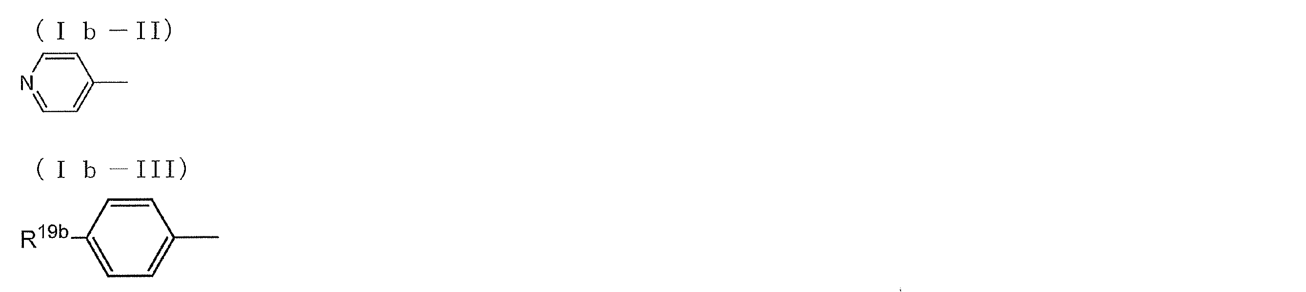
式中、R19bは、置換基を有していてもよいアルキル基、置換基を有していてもよいアリール基、置換基を有していてもよいアルコキシ基、置換基を有していてもよいオキシカルボニル基、置換基を有していてもよいアシルオキシ基を表す。
前記一般式(Ia)及び(Ib)中、各基が有する置換基の例には、一般式(I)中のR11~R14で表される置換基の例と同様である。また、アルキル基等の炭素原子を有する基については、炭素原子数の好ましい範囲は、R11~R14で表される置換基についての炭素原子数の好ましい範囲と同様である。
なお、上記一般式(I)、(Ia)及び(Ib)で表される化合物は置換基として、重合性基を有していてもよい。重合性基を有していると、硬膜性が良化されるので好ましい。重合性基の例には、不飽和重合性基、エポキシ基、及びアジリジニル基が含まれ、不飽和重合性基が好ましく、エチレン性不飽和重合性基が特に好ましい。エチレン性不飽和重合性基の例には、アクリロイル基、及びメタクリロイル基が含まれる。
重合性基は分子末端に位置するのが好ましく、即ち、式(I)中では、R15及び/又はR16の置換基として、並びにAr11の置換基として、存在するのが好ましい。
重合性基は分子末端に位置するのが好ましく、即ち、式(I)中では、R15及び/又はR16の置換基として、並びにAr11の置換基として、存在するのが好ましい。
以下に、式(I)で表されるアゾ色素の具体例を示すが、以下の具体例に限定されるものではない。
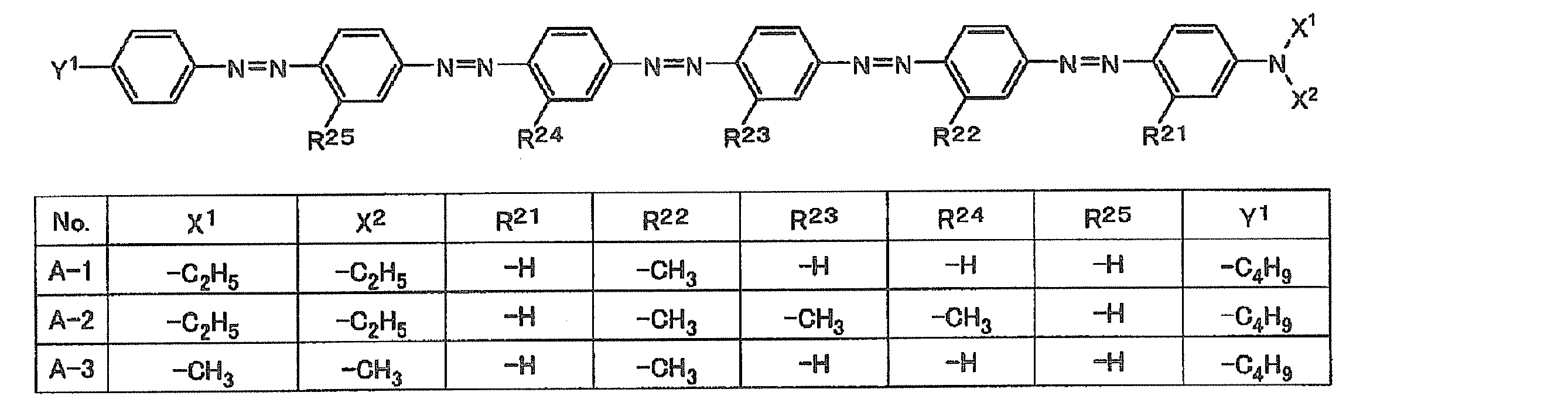




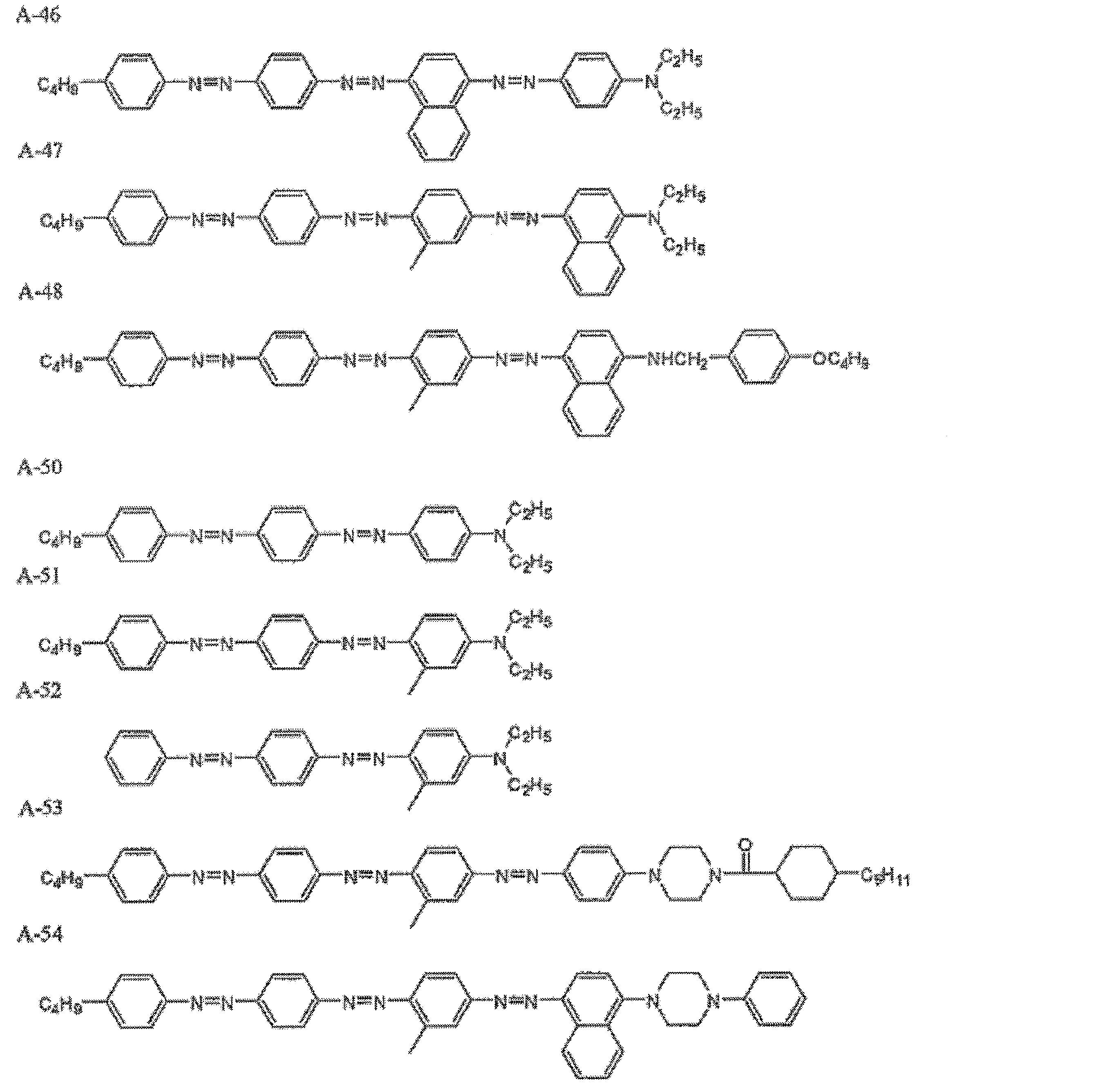
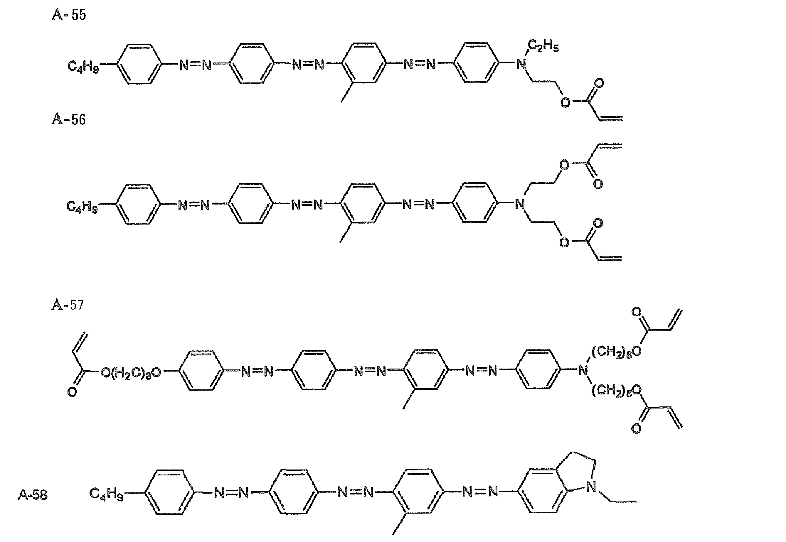
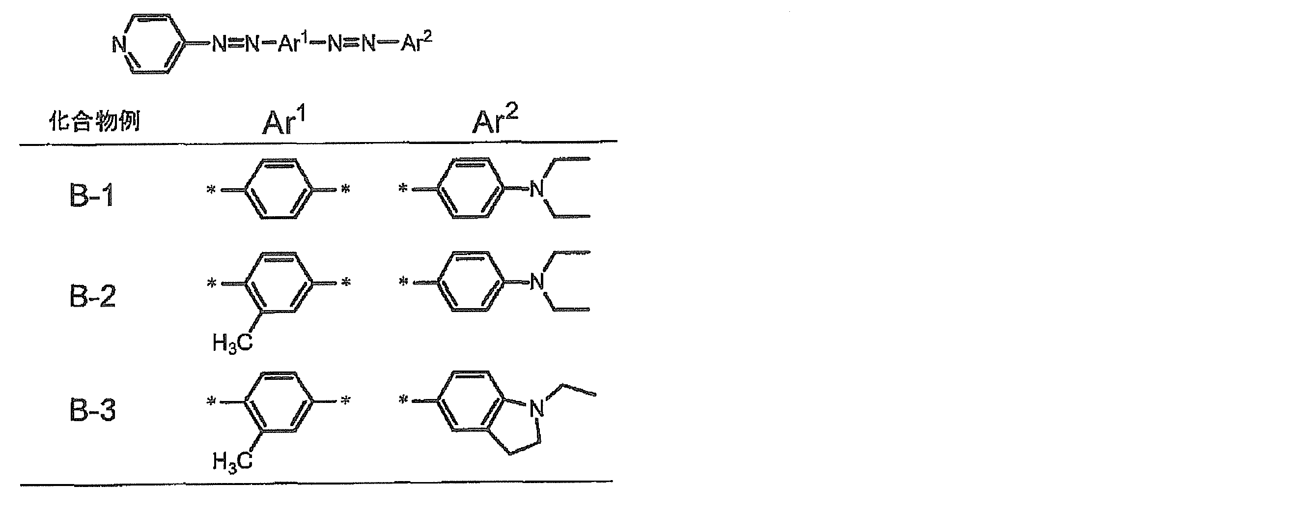
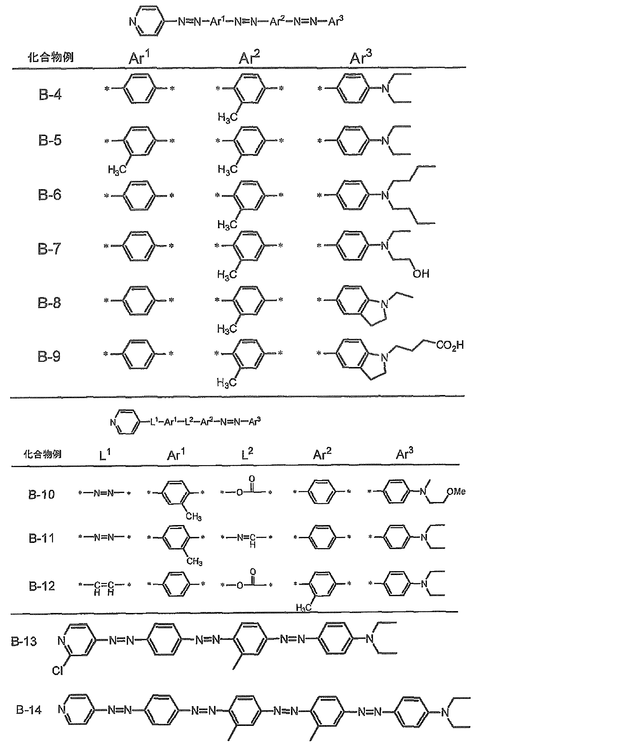
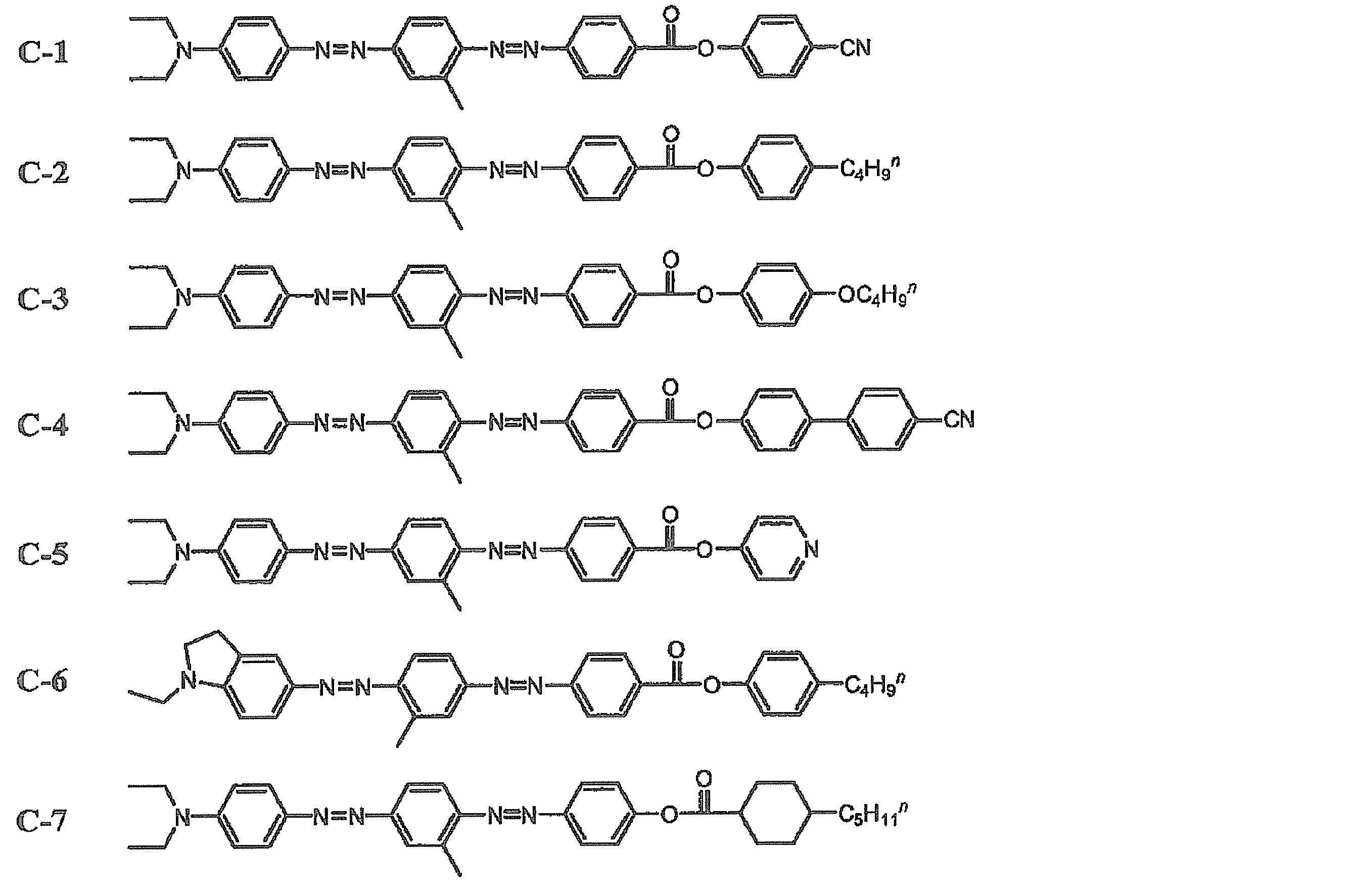
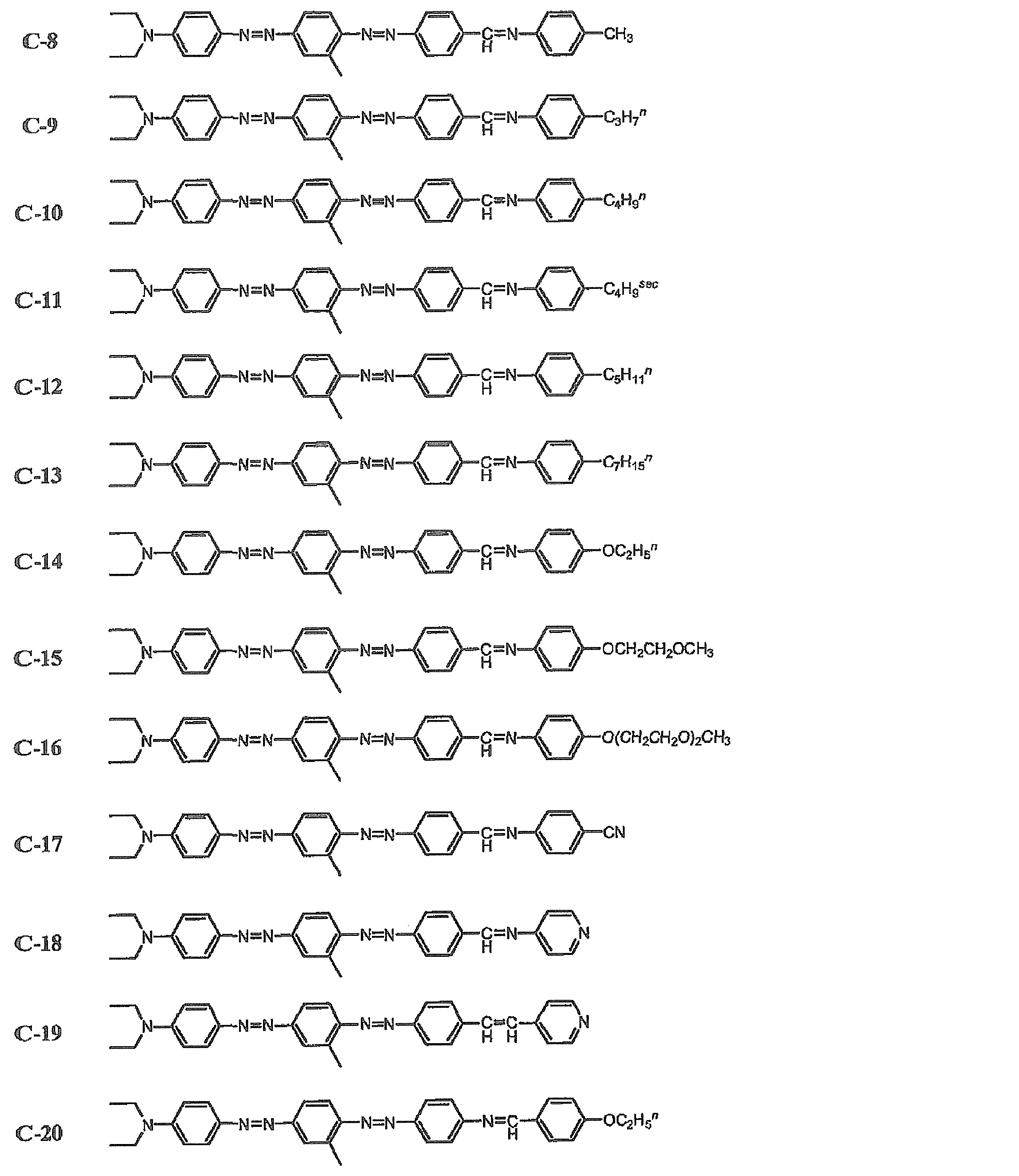
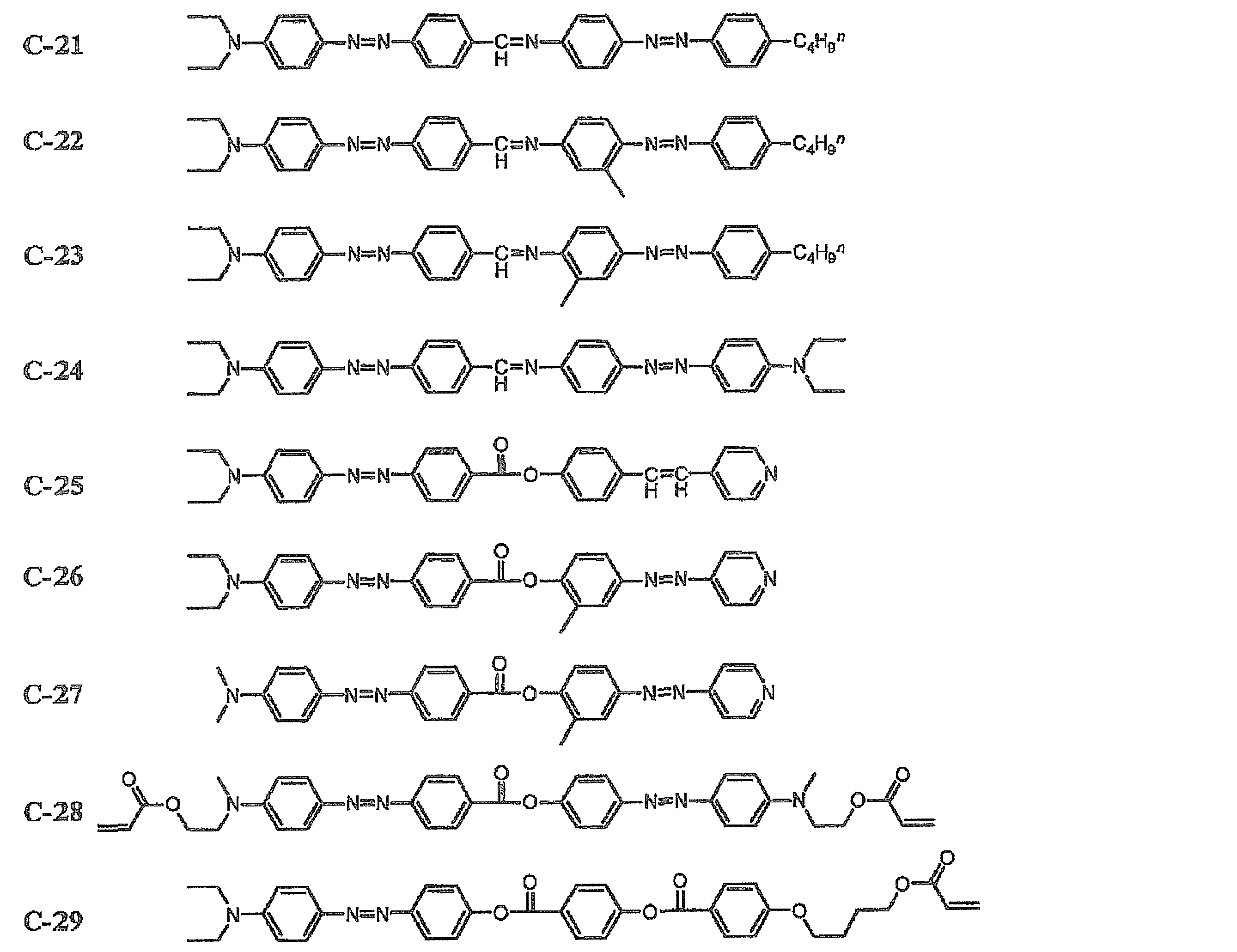

式中、R21及びR22はそれぞれ、水素原子、アルキル基、アルコキシ基、又は-L22-Yで表される置換基を表すが、但し、少なくとも一方は、水素原子以外の基を表す。L22は、アルキレン基を表すが、アルキレン基中に存在する1個のCH2基又は隣接していない2個以上のCH2基はそれぞれ-O-、-COO-、-OCO-、-OCOO-、-NRCOO-、-OCONR-、-CO-、-S-、-SO2-、-NR-、-NRSO2-、又は-SO2NR-(Rは水素原子又は炭素数1~4のアルキル基を表す)に置換されていてもよい。Yは、水素原子、ヒドロキシ基、アルコキシ基、カルボキシル基、ハロゲン原子、又は重合性基を表す。
中でも、R21及びR22の一方が、水素原子又はC1~C4程度の短鎖の置換基であり、R21及びR22の他方が、C5~C30程度の長鎖の置換基であると、溶解性がより改善されるので好ましい。一般的に、液晶性の発現に関しては、その分子形状及び分極率の異方性等が大きく影響することがよく知られており、液晶便覧(2000年、丸善(株))等に詳しく記載されている。棒状液晶分子の代表的な骨格は、剛直なメソゲンと分子長軸方向の柔軟な末端鎖から成っており、式(II)中のR21及びR22に相当する分子短軸方向の側方置換基は、分子の回転を阻害しない小さな置換基とするか、又は置換していないのが一般的である。側方置換基に特徴を持たせた例としては、親水性(例えばイオン性)の側方置換基を導入することで、スメクチック相の安定化した例が知られているが、安定なネマチック相を発現する例はほとんど知られていない。特に、ネマチック相を発現する棒状液晶性分子の特定の置換位置に、長鎖の置換基を導入することで、配向秩序度を低下させることなく、溶解性を向上させた例は、全く知られていない。
R21及びR22がそれぞれ表すアルキル基としては、C1~C30のアルキル基が挙げられる。上記短鎖のアルキル基の例としては、C1~C9が好ましく、C1~C4がより好ましい。一方、上記長鎖のアルキル基としては、C5~C30が好ましく、C10~C30がより好ましく、C10~C20がさらに好ましい。
R21及びR22がそれぞれ表すアルコキシ基としては、C1~C30のアルコキシ基が挙げられる。上記短鎖のアルコキシ基の例としては、C1~C8が好ましく、C1~C3がより好ましい。一方、上記長鎖のアルコキシ基としては、C5~C30が好ましく、C10~C30がより好ましく、C10~C20がさらに好ましい。
R21及びR22がそれぞれ表す-L22-Yで表される置換基のうち、L22が表すアルキレン基は、C5~C30が好ましく、C10~C30がより好ましく、C10~C20がさらに好ましい。前記アルキレン基中に存在する1個のCH2基又は隣接していない2個以上のCH2基はそれぞれ-O-、-COO-、-OCO-、-OCOO-、-NRCOO-、-OCONR-、-CO-、-S-、-SO2-、-NR-、-NRSO2-、及び-SO2NR-(Rは水素原子、又は炭素数1~4のアルキル基を表す)からなる2価基の群から選択された1以上によって置換されていてもよい。勿論、前記2価基の群から選択される2以上の基によって置換されていてもよい。また、L22の末端であって、Yと結合するCH2が、上記2価の基のいずれかで置換されていてもよい。また、L22の先端であって、フェニル基と結合するCH2が、上記2価の基のいずれかで置換されていてもよい。
特に、溶解性向上の観点では、L22がアルキレンオキシ基である、又はアルキレンオキシ基を含んでいるのが好ましく、L22が、-(OCH2CH2)p-(但し、pは3以上の数を表し、3~10であるのが好ましく、3~6であるのがより好ましい)で表されるポリエチレンオキシ基であるか、又はポリエチレンオキシ基を含んでいるのがさらに好ましい。
以下に、-L22-の例を示すが、以下の例に限定されるものではない。下記式中、qは1以上の数であり、1~10であるのが好ましく、2~6であるのがより好ましい。また、rは5~30であり、好ましくは10~30であり、より好ましくは10~20である。
-(OCH2CH2)p-
-(OCH2CH2)p-O-(CH2)q-
-(OCH2CH2)p-OC(=O)-(CH2)q-
-(OCH2CH2)p-OC(=O)NH-(CH2)q-
-O(CH2)r-
-(CH2)r-
以下に、-L22-の例を示すが、以下の例に限定されるものではない。下記式中、qは1以上の数であり、1~10であるのが好ましく、2~6であるのがより好ましい。また、rは5~30であり、好ましくは10~30であり、より好ましくは10~20である。
-(OCH2CH2)p-
-(OCH2CH2)p-O-(CH2)q-
-(OCH2CH2)p-OC(=O)-(CH2)q-
-(OCH2CH2)p-OC(=O)NH-(CH2)q-
-O(CH2)r-
-(CH2)r-
R21及びR22がそれぞれ表す-L22-Yで表される置換基のうち、Yは、水素原子、ヒドロキシ基、アルコキシ基(好ましくはC1~C10、より好ましくはC1~C5のアルコキシ基である)、カルボキシル基、ハロゲン原子、又は重合性基を表す。
L22とYとの組合せにより、-L22-Yの末端は、例えばカルボキシル基やアミノ基、アンモニウム基などの分子間相互作用を強める置換基となり得るし、またスルホニルオキシ基、ハロゲン原子等の脱離基にもなり得る。
また、-L22-Yの末端は、架橋性基、重合性基など、他分子と共有結合を形成する置換基であってもよく、例えば、-O-C(=O)CH=CH2、及び-O-C(=O)C(CH3)=CH2等の重合性基であってもよい。
L22とYとの組合せにより、-L22-Yの末端は、例えばカルボキシル基やアミノ基、アンモニウム基などの分子間相互作用を強める置換基となり得るし、またスルホニルオキシ基、ハロゲン原子等の脱離基にもなり得る。
また、-L22-Yの末端は、架橋性基、重合性基など、他分子と共有結合を形成する置換基であってもよく、例えば、-O-C(=O)CH=CH2、及び-O-C(=O)C(CH3)=CH2等の重合性基であってもよい。
硬化膜用の材料として利用する場合は、Yは、重合性基であることが好ましい(但し、前記式(II)の化合物が重合性基を有していなくても、併用される化合物が重合性であれば、当該他の化合物の重合反応を進行させることで、式(II)の化合物の配向を固定することができる)。重合反応は、付加重合(開環重合を含む)又は縮合重合であることが好ましい。すなわち、重合性基は、付加重合反応又は縮合重合反応が可能な官能基であることが好ましい。前記式で表される重合性基の例には、下記式(M-1)で表されるアクリレート基、及び下記式(M-2)で表されるメタクリレート基が含まれる。

また、開環重合性基も好ましく、例えば、環状エーテル基が好ましく、エポキシ基又はオキセタニル基がより好ましく、エポキシ基が特に好ましい。
前記一般式(II)中、L21はそれぞれ、アゾ基(-N=N-)、カルボニルオキシ基(-C(=O)O-)、オキシカルボニル基(-O-C(=O)-)、イミノ基(-N=CH-)、及びビニレン基(-C=C-)からなる群から選ばれる連結基を表す。中でも、ビニレン基が好ましい。
前記前記一般式(II)中、Dyeはそれぞれ、下記一般式(IIa)で表されるアゾ色素残基を表す。

式(IIa)中、*はL21との結合部を表し;X21は、ヒドロキシ基、置換もしくは無置換のアルキル基、置換もしくは無置換のアルコキシ基、無置換アミノ基、又はモノもしくはジアルキルアミノ基を表し;Ar21は、それぞれ置換基を有していてもよい芳香族炭化水素環又は芳香族複素環を表し;nは1~3の整数を表し、nが2以上の時、複数あるAr21は互いに同一でも異なっていてもよい。
X21で表されるアルキル基は、好ましくはC1~C12、より好ましくは、C1~C6のアルキル基である。具体的には、メチル基、エチル基、プロピル基、ブチル基等が含まれる。アルキル基は置換基を有していてもよく、該置換基の例には、ヒドロキシ基、カルボキシル基、及び重合性基が含まれる。重合性基の好ましい例は、上記Yが表す重合性基の好ましい例と同様である。
X21で表されるアルコキシは、好ましくはC1~C20、より好ましくはC1~C10、さらに好ましくはC1~C6のアルコキシ基である。具体的には、メトキシ基、エトキシ基、プロピオキシ基、ブトキシ基、ペンタオキシ基、ヘキサオキシ基、ヘプタオキシ基、オクタオキシ基などが挙げられる。アルコキシ基は置換基を有していてもよく、該置換基の例には、ヒドロキシ基、カルボキシル基、及び重合性基が含まれる。重合性基の好ましい例は、上記Yが表す重合性基の好ましい例と同様である。
X21で表される置換もしくは無置換のアミノ基は、好ましくはC0~C20、より好ましくはC0~10、さらに好ましくはC0~C6のアミノ基である。具体的には、無置換アミノ基、メチルアミノ基、ジメチルアミノ基、ジエチルアミノ基、メチル・ヘキシルアミノ基、アニリノ基などが挙げられる。
中でも、X21はアルコキシ基であるのが好ましい。
前記一般式(II)中、Ar21は、置換基を有していてもよい芳香族炭化水素環基又は芳香族複素環基を表す。芳香族炭化水素環基及び芳香族複素環基の例には、1,4-フェニレン基、1,4-ナフチレン基、ピリジン環基、ピリミジン環基、ピラジン環基、キノリン環基、チオフェン環基、チアゾール環基、チアジアゾール環基、チエノチアゾール環基などが含まれる。中でも、1,4-フェニレン基、1,4-ナフチレン基、チエノチアゾール環基が好ましく、1,4-フェニレン基が最も好ましい。
Ar21が有してもよい置換基としては、炭素数1~10のアルキル基、ヒドロキシ基、炭素数1~10のアルコキシ基、シアノ基などが好ましく、炭素数1~2のアルキル基、炭素数1~2のアルコキシ基がより好ましい。
nは、1又は2であるのが好ましく、1がより好ましい。
前記一般式(II)で表される化合物の例には、以下の一般式(IIb)で表される化合物が含まれる。式中の各記号の意義は、式(II)中のそれぞれと同義であり、好ましい範囲も同様である。

式中、X21は互いに同一又は異なり、C1-12のアルコキシ基を表すのが好ましく;R21及びR22は互いに異なっているのが好ましく、R21及びR22の一方が、水素原子又はC1~C4の短鎖の置換基(アルキル基、アルコキシ基、又は-L22-Yで表される置換基)であり、R21及びR22の他方が、C5~C30の長鎖の置換基(アルキル基、アルコキシ基、又は-L22-Yで表される置換基)であるのが好ましい。あるいは、R21及びR22はそれぞれ、-L22-Yで表される置換基であり、L22がアルキレンオキシ基である、又はアルキレンオキシ基を含んでいるのも好ましい。
以下に、前記一般式(II)で表される化合物の具体例を示すが、以下の化合物例に限定されるものではない。
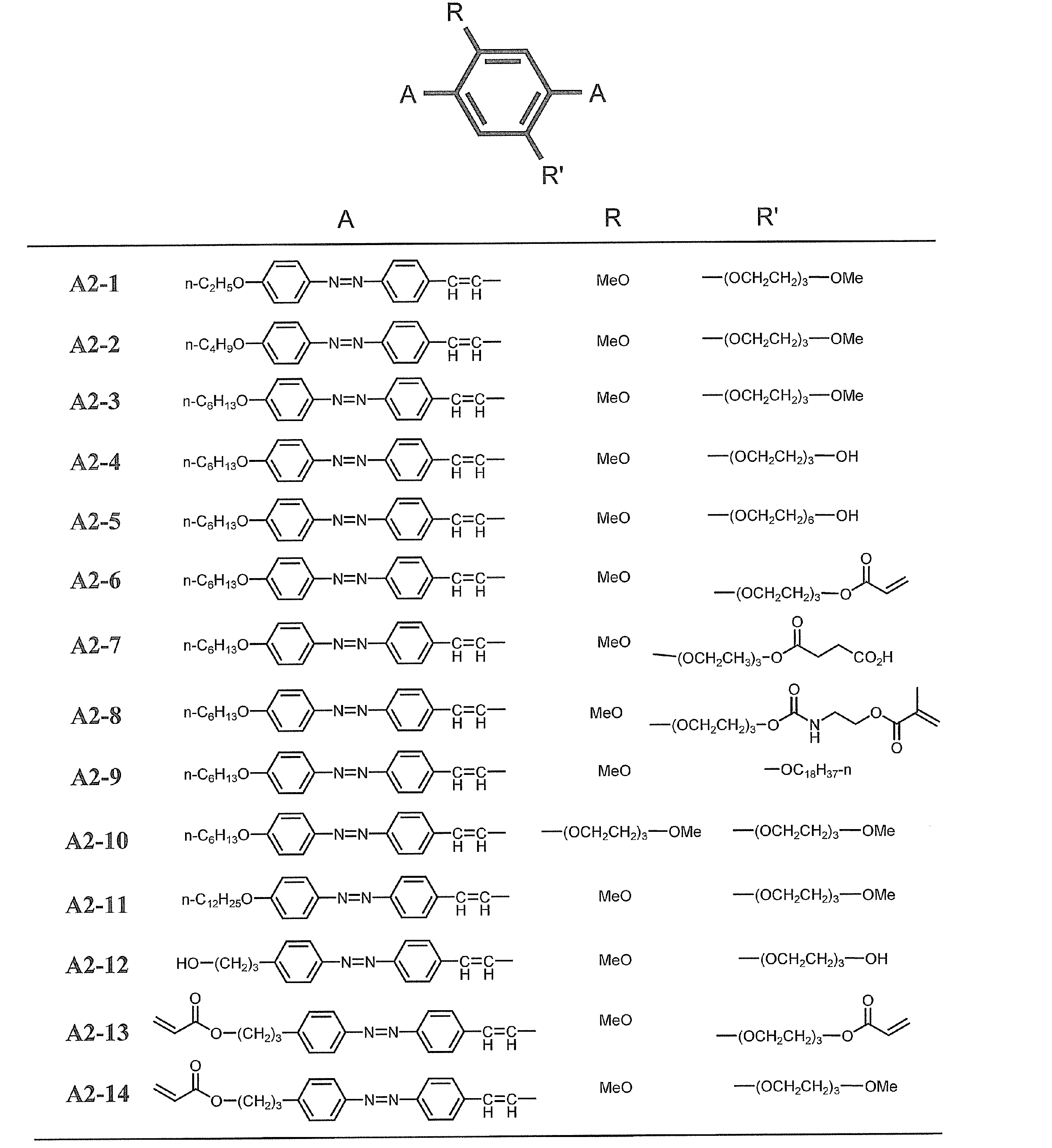

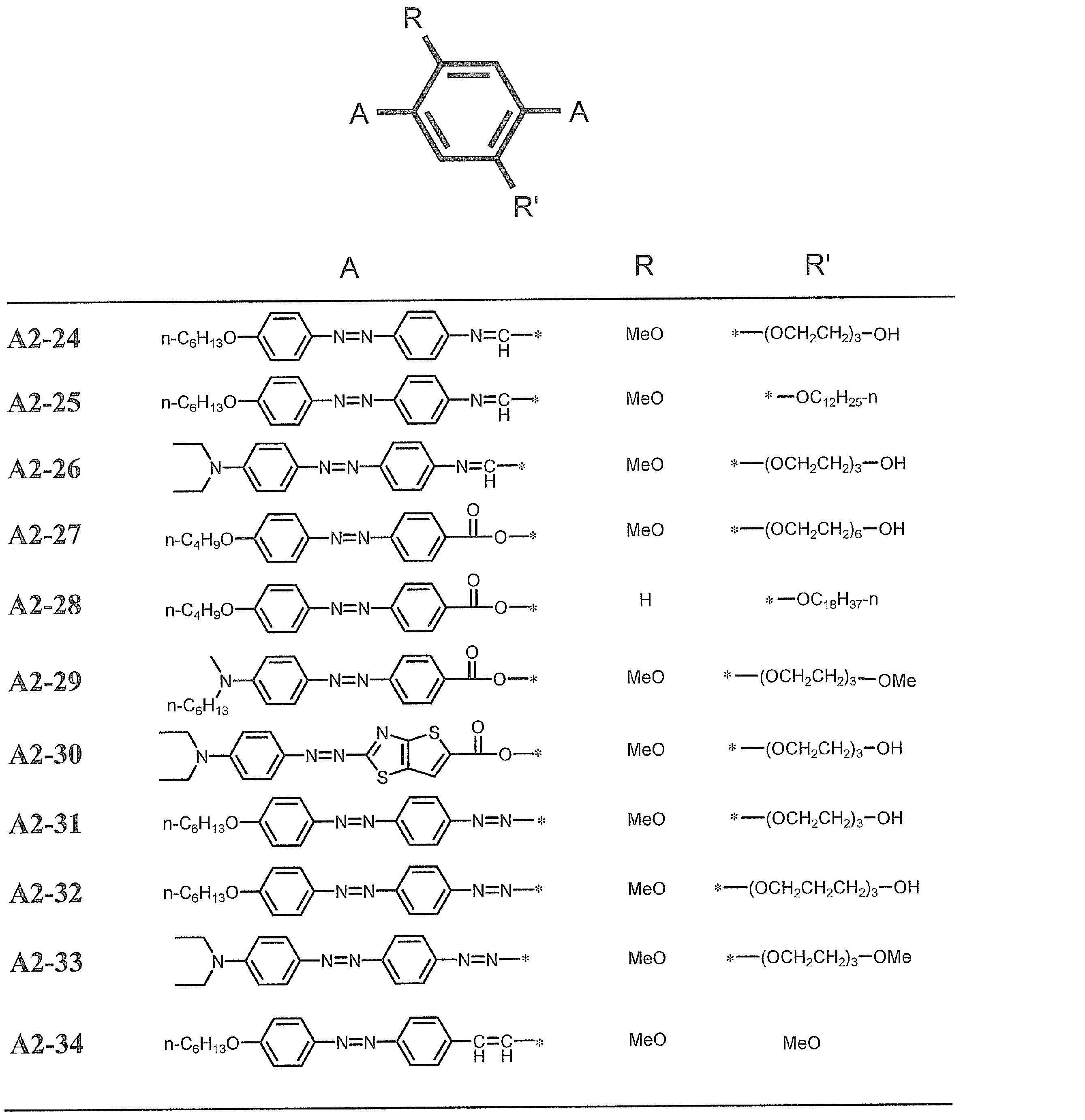

式中、R31~R35はそれぞれ独立に、水素原子又は置換基を表し;R36及びR37はそれぞれ独立に水素原子又は置換基を有していてもよいアルキル基を表し;Q31は置換基を有していてもよい芳香族炭化水素基、芳香族複素環基又はシクロヘキサン環基を表し;L31は2価の連結基を表し;A31は酸素原子又は硫黄原子を表す。
R31~R35で表される置換基の例としては、前記式(I)中のR11~R14がそれぞれ表す置換基の例と同様である。好ましくは水素原子、アルキル基、アルコキシ基、ハロゲン原子であり、特に好ましくは水素原子、アルキル基、アルコキシ基であり、最も好ましくは水素原子又はメチル基である。
前記一般式(III)において、R36及びR37で表される置換基を有していてもよいアルキル基としては、好ましくは炭素数1~20、より好ましくは炭素数1~12、特に好ましくは炭素数1~8のアルキル基であり、例えば、メチル基、エチル基、n-オクチル基などが挙げられる。R36及びR37で表されるアルキル基の置換基としては、前記R31~R35で表される置換基と同義である。R36及びR37がアルキル基を表す場合、互いに連結して環構造を形成してもよい。R36又はR37がアルキル基を表す場合、それぞれR32又はR34と連結して環構造を形成してもよい。
R36及びR37で表される基としては、特に好ましくは水素原子又はアルキル基であり、さらに好ましくは水素原子、メチル基又はエチル基である。
R36及びR37で表される基としては、特に好ましくは水素原子又はアルキル基であり、さらに好ましくは水素原子、メチル基又はエチル基である。
前記一般式(III)において、Q31は置換基を有していてもよい芳香族炭化水素基(好ましくは炭素数1~20、より好ましくは炭素数1~10であり、例えば、フェニル基、ナフチル基などが挙げられる)、置換基を有していてもよい芳香族複素環基又は置換基を有していてもよいシクロヘキサン環基を表す。
Q31で表される基が有していてもよい置換基としては、アゾ化合物の溶解性やネマチック液晶性を高めるために導入される基、色素としての色調を調節するために導入される電子供与性や電子吸引性を有する基、又は配向を固定化するために導入される重合性基を有する基が好ましく、具体的には、前記R31~R35で表される置換基と同義である。好ましくは、置換基を有していてもよいアルキル基、置換基を有していてもよいアルケニル基、置換基を有していてもよいアルキニル基、置換基を有していてもよいアリール基、置換基を有していてもよいアルコキシ基、置換基を有していてもよいオキシカルボニル基、置換基を有していてもよいアシルオキシ基、置換基を有していてもよいアシルアミノ基、置換基を有していてもよいアミノ基、置換基を有していてもよいアルコキシカルボニルアミノ基、置換基を有していてもよいスルホニルアミノ基、置換基を有していてもよいスルファモイル基、置換基を有していてもよいカルバモイル基、置換基を有していてもよいアルキルチオ基、置換基を有していてもよいスルホニル基、置換基を有していてもよいウレイド基、ニトロ基、ヒドロキシ基、シアノ基、イミノ基、アゾ基、ハロゲン原子であり、特に好ましくは、置換基を有していてもよいアルキル基、置換基を有していてもよいアルケニル基、置換基を有していてもよいアリール基、置換基を有していてもよいアルコキシ基、置換基を有していてもよいオキシカルボニル基、置換基を有していてもよいアシルオキシ基、ニトロ基、イミノ基、アゾ基である。これらの置換基のうち、炭素原子を有するものについては、炭素原子数の好ましい範囲は、R31~R35で表される置換基についての炭素原子数の好ましい範囲と同様である。
Q31で表される基が有していてもよい置換基としては、アゾ化合物の溶解性やネマチック液晶性を高めるために導入される基、色素としての色調を調節するために導入される電子供与性や電子吸引性を有する基、又は配向を固定化するために導入される重合性基を有する基が好ましく、具体的には、前記R31~R35で表される置換基と同義である。好ましくは、置換基を有していてもよいアルキル基、置換基を有していてもよいアルケニル基、置換基を有していてもよいアルキニル基、置換基を有していてもよいアリール基、置換基を有していてもよいアルコキシ基、置換基を有していてもよいオキシカルボニル基、置換基を有していてもよいアシルオキシ基、置換基を有していてもよいアシルアミノ基、置換基を有していてもよいアミノ基、置換基を有していてもよいアルコキシカルボニルアミノ基、置換基を有していてもよいスルホニルアミノ基、置換基を有していてもよいスルファモイル基、置換基を有していてもよいカルバモイル基、置換基を有していてもよいアルキルチオ基、置換基を有していてもよいスルホニル基、置換基を有していてもよいウレイド基、ニトロ基、ヒドロキシ基、シアノ基、イミノ基、アゾ基、ハロゲン原子であり、特に好ましくは、置換基を有していてもよいアルキル基、置換基を有していてもよいアルケニル基、置換基を有していてもよいアリール基、置換基を有していてもよいアルコキシ基、置換基を有していてもよいオキシカルボニル基、置換基を有していてもよいアシルオキシ基、ニトロ基、イミノ基、アゾ基である。これらの置換基のうち、炭素原子を有するものについては、炭素原子数の好ましい範囲は、R31~R35で表される置換基についての炭素原子数の好ましい範囲と同様である。
該芳香族炭化水素基、該芳香族複素環基又は該シクロヘキサン環基は、これら置換基を1~5個有していてもよく、好ましくは1個有していることである。Q31がフェニル基である場合は、L31に対してパラ位に1個置換基を有しているのが好ましく、シクロヘキサン環基である場合は、L31に対して4位にトランス配置となるように1個置換基を有しているのが好ましい。
Q31で表される芳香族複素環基としては、単環又は二環性の複素環由来の基が好ましい。芳香族複素環基を構成する炭素以外の原子としては、窒素原子、硫黄原子及び酸素原子が挙げられる。芳香族複素環基が炭素以外の環を構成する原子を複数有する場合、これらは同一であっても異なっていてもよい。芳香族複素環基として具体的には、ピリジル基、キノリル基、チオフェニル基、チアゾリル基、ベンゾチアゾリル基、チアジアゾリル基、キノロニル基、ナフタルイミドイル基、チエノチアゾリル基などが挙げられる。
芳香族複素環基としては、ピリジル基、キノリル基、チアゾリル基、ベンゾチアゾリ基、チアジアゾリル基、又はチエノチアゾリル基が好ましく、ピリジル基、ベンゾチアゾリル基、チアジアゾリル基、又はチエノチアゾリル基が特に好ましく、ピリジル基、ベンゾチアゾリル基、又はチエノチアゾリル基が最も好ましい。
芳香族複素環基としては、ピリジル基、キノリル基、チアゾリル基、ベンゾチアゾリ基、チアジアゾリル基、又はチエノチアゾリル基が好ましく、ピリジル基、ベンゾチアゾリル基、チアジアゾリル基、又はチエノチアゾリル基が特に好ましく、ピリジル基、ベンゾチアゾリル基、又はチエノチアゾリル基が最も好ましい。
Q31で表される基としては、特に好ましくは置換基を有していてもよいフェニル基、ナフチル基、ピリジル基、ベンゾチアゾリル基、チエノチアゾリル基又はシクロヘキサン環基であり、より好ましくは、フェニル基、ピリジル基、ベンゾチアゾリル基又はシクロヘキサン環基である。
前記一般式(III)において、L31で表される連結基としては、単結合、アルキレン基(好ましくは炭素数1~20、より好ましくは炭素数1~10、特に好ましくは炭素数1~6であり、例えば、メチレン基、エチレン基、プロピレン基、ブチレン基、ペンチレン基、シクロヘキサン-1,4-ジイル基などが挙げられる)、アルケニレン基(好ましくは炭素数2~20、より好ましくは炭素数2~10、特に好ましくは炭素数2~6であり、例えば、エテニレン基などが挙げられる)、アルキニレン基(好ましくは炭素数2~20、より好ましくは炭素数2~10、特に好ましくは炭素数2~6であり、例えば、エチニレン基などが挙げられる)、アルキレンオキシ基(好ましくは炭素数1~20、より好ましくは炭素数1~10、特に好ましくは炭素数1~6であり、例えば、メチレンオキシ基などが挙げられる)、アミド基、エーテル基、アシルオキシ基(-C(=O)O-)、オキシカルボニル基(-OC(=O)-)、イミノ基(-CH=N-もしくは-N=CH-)、スルホアミド基、スルホン酸エステル基、ウレイド基、スルホニル基、スルフィニル基、チオエーテル基、カルボニル基、-NR-基(ここで、Rは水素原子、アルキル基又はアリール基を表す)、アゾ基、アゾキシ基、又はこれらを2つ以上組合せて構成される炭素数0~60の2価の連結基が挙げられる。
L31で表される基としては、特に好ましくは単結合、アミド基、アシルオキシ基、オキシカルボニル基、イミノ基、アゾ基又はアゾキシ基であり、よりさらに好ましくはアゾ基、アシルオキシ基、オキシカルボニル基、又はイミノ基である。
前記一般式(III)において、A31は酸素原子又は硫黄原子を表し、好ましくは硫黄原子である。
前記一般式(III)で表される化合物は、置換基として、重合性基を有していてもよい。重合性基を有していると、硬膜性が良化されるので好ましい。重合性基の例には、不飽和重合性基、エポキシ基、及びアジリジニル基が含まれ、不飽和重合性基が好ましく、エチレン性不飽和重合性基が特に好ましい。エチレン性不飽和重合性基の例には、アクリロイル基、及びメタクリロイル基が含まれる。
重合性基は分子末端に位置するのが好ましく、即ち、式(III)中では、R36及び/又はR37の置換基として、並びにQ1の置換基として、存在するのが好ましい。
重合性基は分子末端に位置するのが好ましく、即ち、式(III)中では、R36及び/又はR37の置換基として、並びにQ1の置換基として、存在するのが好ましい。
前記一般式(III)で表される化合物のうち、特に好ましいものは、下記一般式(IIIa)で表される化合物である。

式中、R31~R35については、上記式(III)中のそれぞれと同義であり、好ましい範囲も同様である。B31は窒素原子又は置換基を有していてもよい炭素原子を表し;L32はアゾ基、アシルオキシ基(-C(=O)O-)、オキシカルボニル基(-OC(=O)-)、又はイミノ基を表す。
前記一般式(IIIa)において、R35は水素原子又はメチル基を表すのが好ましく、より好ましくは水素原子である。
前記一般式(IIIa)において、B31が炭素原子の場合に有していてもよい置換基は、前記一般式(III)においてQ31が有していてもよい置換基と同義であり、好ましい範囲も同一である。
前記一般式(IIIa)において、L32はアゾ基、アシルオキシ基、オキシカルボニル基、又はイミノ基を表し、好ましくはアゾ基又はアシルオキシ基、オキシカルボニル基であり、より好ましくはアゾ基である。
前記一般式(IIIa)において、L32はアゾ基、アシルオキシ基、オキシカルボニル基、又はイミノ基を表し、好ましくはアゾ基又はアシルオキシ基、オキシカルボニル基であり、より好ましくはアゾ基である。
以下に、式(III)で表される化合物の具体例を示すが、以下の具体例に限定されるものではない。
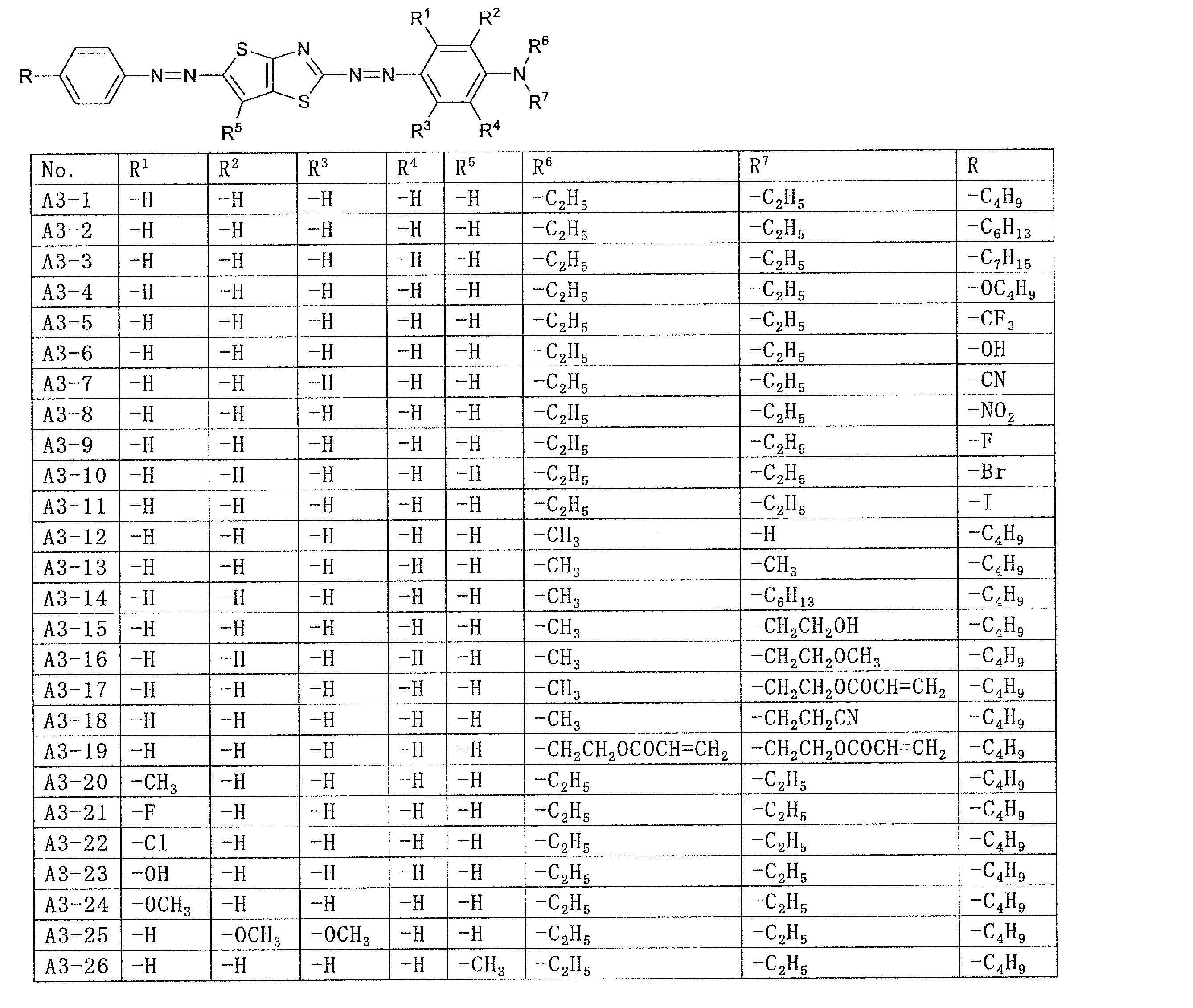
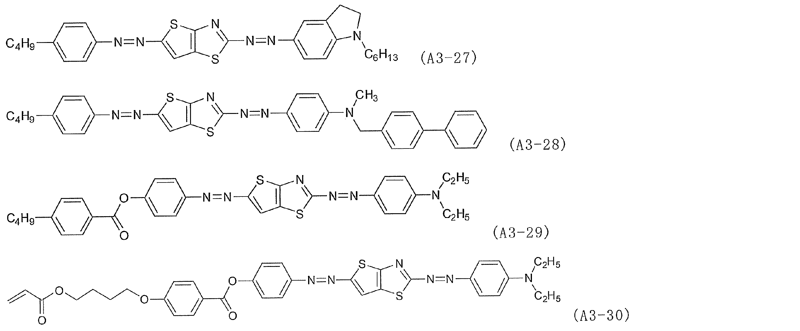

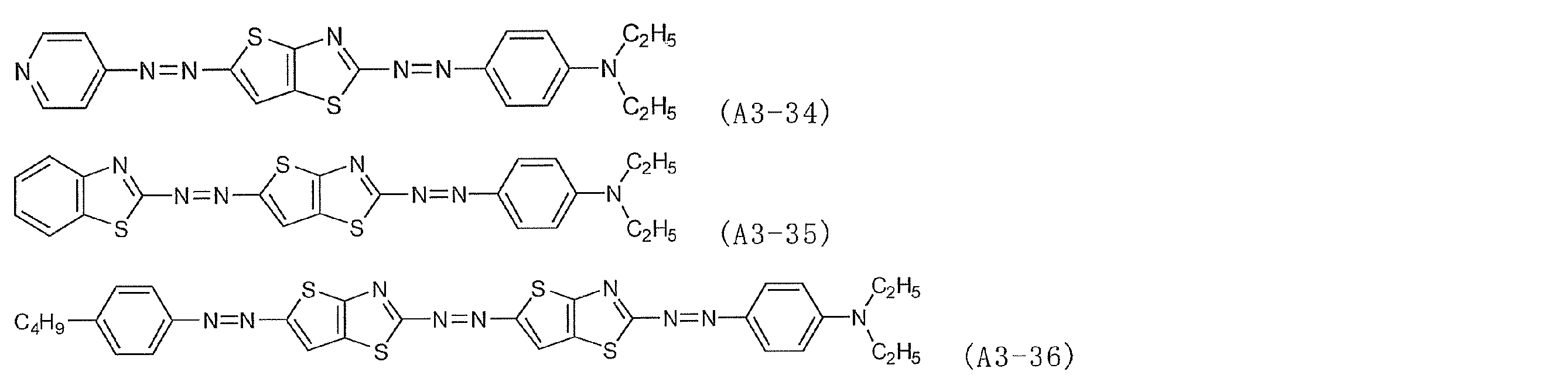


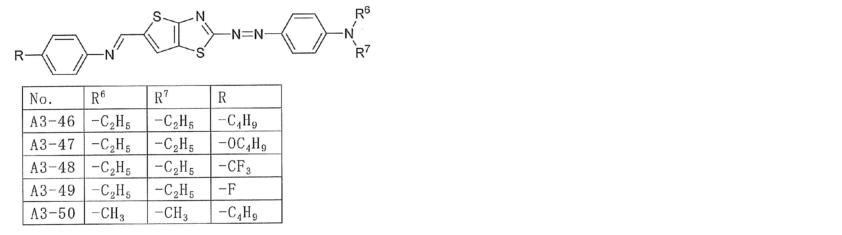
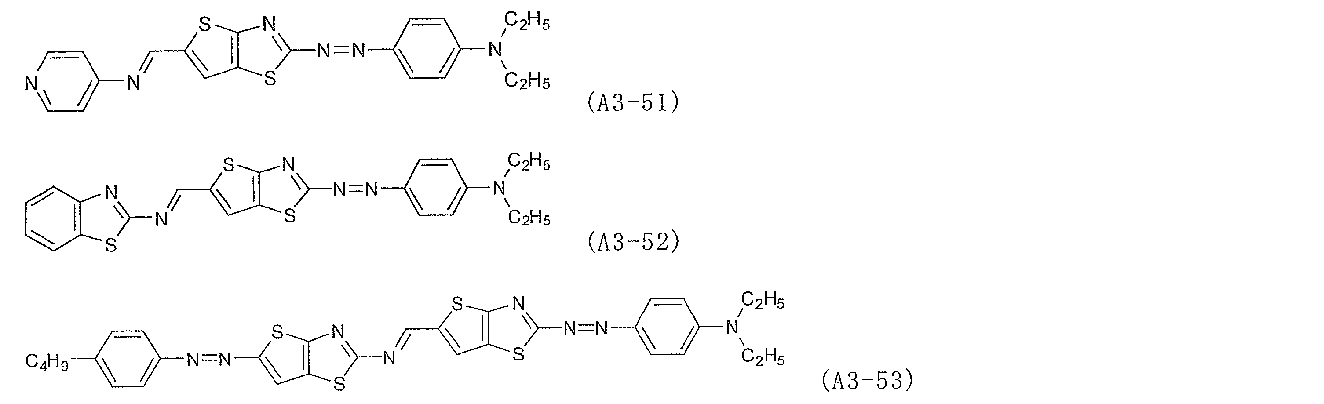

式中、R41及びR42はそれぞれ、水素原子又は置換基を表し、互いに結合して環を形成していてもよく;Ar4は、置換されていてもよい2価の芳香族炭化水素基又は芳香族複素環基を表し;R43及びR44はそれぞれ、水素原子、又は置換されていてもよいアルキル基を表し、互いに結合して複素環を形成していてもよい。
一般式(IV)において、R41及びR42がそれぞれ表す置換基の例としては、前記一般式(I)中のR11~R14がそれぞれ表す置換基の例と同様である。R41及びR42としては、好ましくは水素原子、アルキル基、アルコキシ基、ハロゲン原子、シアノ基、ニトロ基、スルホ基であり、より好ましくは水素原子、アルキル基、ハロゲン原子、シアノ基、ニトロ基であり、さらに好ましくは水素原子、アルキル基、シアノ基であり、よりさらに好ましくは水素原子、メチル基、シアノ基である。
R41とR42は互いに連結して環を形成することも好ましい。特に芳香族炭化水素基又は芳香族複素環基を形成することが好ましい。芳香族複素環基としては、単環又は二環性の複素環由来の基が好ましい。芳香族複素環基を構成する炭素以外の原子としては、窒素原子、硫黄原子及び酸素原子が挙げられる。芳香族複素環基が炭素以外の環を構成する原子を複数有する場合、これらは同一であっても異なっていてもよい。芳香族複素環基として具体的には、ピリジン環、ピラジン環、ピリミジン環、ピリダジン環、キノリン環、チオフェン環、チアゾール環、ベンゾチアゾール環、チアジアゾール環、キノロン環、ナフタルイミド環、チエノチアゾール環などが挙げられる。
R41とR42が互いに連結して形成する環状基は、好ましくはベンゼン環、ナフタレン環、ピリジン環、ピラジン環、ピリミジン環、ピリダジン環であり、より好ましくはベンゼン環又はピリジン環であり、もっとも好ましくはピリジン環である。
R41とR42は互いに連結して形成する環状基は置換基を有していてもよく、その範囲はR1、R2で表される基と同様であり、好ましい範囲も同様である。
R41とR42が互いに連結して形成する環状基は、好ましくはベンゼン環、ナフタレン環、ピリジン環、ピラジン環、ピリミジン環、ピリダジン環であり、より好ましくはベンゼン環又はピリジン環であり、もっとも好ましくはピリジン環である。
R41とR42は互いに連結して形成する環状基は置換基を有していてもよく、その範囲はR1、R2で表される基と同様であり、好ましい範囲も同様である。
前記一般式(IV)で表される化合物の例には、以下の一般式(IV’)で表される化合物が含まれる。

式中、式(IV)中と同一の符号は、それぞれ同義であり、好ましい範囲も同様である。A42は、N又はCHを表し、R47及びR48はそれぞれ、水素原子又は置換基を表す。R47及びR48のいずれか一方は置換基であるのが好ましく、双方が置換基であるのも好ましい。置換基の好ましい例は、R41及びR42が表す置換基の例と同様であり、即ち、アルキル基、アルコキシ基、ハロゲン原子、シアノ基、ニトロ基、スルホ基であるのが好ましく、より好ましくは、アルキル基、ハロゲン原子、シアノ基、ニトロ基であり、さらに好ましくはアルキル基、シアノ基であり、最も好ましくはメチル基、シアノ基である。例えば、R47及びR48のいずれか一方が炭素原子数1~4のアルキル基であり、他方がシアノ基である化合物例も好ましい。
一般式(IV’)において、Ar4で表される芳香族複素環基としては、単環又は二環性の複素環由来の基が好ましい。芳香族複素環基を構成する炭素以外の原子としては、窒素原子、硫黄原子及び酸素原子が挙げられる。芳香族複素環基が炭素以外の環を構成する原子を複数有する場合、これらは同一であっても異なっていてもよい。芳香族複素環基として具体的には、ピリジン環、ピラジン環、ピリミジン環、ピリダジン環、キノリン環、チオフェン環、チアゾール環、ベンゾチアゾール環、チアジアゾール環、キノロン環、ナフタルイミド環、チエノチアゾール環などが挙げられる。
Ar4で表される基は、好ましくはベンゼン環、ナフタレン環、ピリジン環、ピラジン環、ピリミジン環、ピリダジン環、キノリン環、チオフェン環であり、より好ましくはベンゼン環、ナフタレン環、ピリジン環、チオフェン環であり、もっとも好ましくはベンゼン環である。
Ar4は置換基を有していてもよく、その範囲は前記R41、R42で表される基と同様である。
Ar4が有していてもよい置換基は、好ましくは、アルキル基、アルコキシ基、ハロゲン原子であり、より好ましくは水素原子、アルキル基、アルコキシ基であり、よりさらに好ましくは、メチル基である。Ar4は無置換であるのも好ましい。
Ar4で表される基は、好ましくはベンゼン環、ナフタレン環、ピリジン環、ピラジン環、ピリミジン環、ピリダジン環、キノリン環、チオフェン環であり、より好ましくはベンゼン環、ナフタレン環、ピリジン環、チオフェン環であり、もっとも好ましくはベンゼン環である。
Ar4は置換基を有していてもよく、その範囲は前記R41、R42で表される基と同様である。
Ar4が有していてもよい置換基は、好ましくは、アルキル基、アルコキシ基、ハロゲン原子であり、より好ましくは水素原子、アルキル基、アルコキシ基であり、よりさらに好ましくは、メチル基である。Ar4は無置換であるのも好ましい。
Ar4とアミノ基の結合は、Ar4とアゾ基の結合と平行であることが、分子の直線性を高め、より大きな分子長及びアスペクト比を得られるため好ましい。例えばAr4がアゾ基及びアミノ基と結合した6員環を含む場合、アミノ基はアゾ基に対して4位に結合していることが好ましく、アゾ基及びアミノ基と結合した5員環を含む場合、アミノ基はアゾ基に対して3位又は4位に結合していることが好ましい。
一般式(IV’)において、R43及びR44で表されるアルキル基の範囲は前記R41、R42で表されるアルキル基と同様である。該アルキル基は置換基を有していてもよく、当該置換基の例は、R41、R42で表される置換基の例と同様である。R43及びR44が置換されていてもよいアルキル基を表す場合、互いに結合して複素環を形成していてもよい。また、可能な場合にはAr4が有する置換基と結合して環を形成していてもよい。
R43とR44は互いに連結して環を形成することが好ましい。好ましくは6員環又は5員環であり、より好ましくは6員環である。該環状基は、炭素とともに、炭素以外の原子を構成原子として有していてもよい。炭素以外の構成原子としては、窒素原子、硫黄原子及び酸素原子が挙げられる。該環状基が炭素以外の環を構成する原子を複数有する場合、これらは同一であっても異なっていてもよい。
R43とR44からなる環状基として具体的には、3-ピロリン環、ピロリジン環、3-イミダゾリン環、イミダゾリジン環、4-オキサゾリン環、オキサゾリジン環、4-チアゾリン環、チアゾリジン環、ピペリジン環、ピペラジン環、モルホリン環、チオモルホリン環、アゼパン環、アゾカン環などが挙げられる。
R43とR44からなる環状基は、好ましくはピロリジン環、ピペリジン環、ピペラジン環、モルホリン環であり、より好ましくはピペリジン環、ピペラジン環であり、もっとも好ましくはピペラジン環である。
R43とR44からなる環状基として具体的には、3-ピロリン環、ピロリジン環、3-イミダゾリン環、イミダゾリジン環、4-オキサゾリン環、オキサゾリジン環、4-チアゾリン環、チアゾリジン環、ピペリジン環、ピペラジン環、モルホリン環、チオモルホリン環、アゼパン環、アゾカン環などが挙げられる。
R43とR44からなる環状基は、好ましくはピロリジン環、ピペリジン環、ピペラジン環、モルホリン環であり、より好ましくはピペリジン環、ピペラジン環であり、もっとも好ましくはピペラジン環である。
R43とR44からなる環状基は置換基を有していてもよく、その範囲はR41及びR42で表される基と同様である。該環状基は剛直な直線状の置換基を一つ有し、該環状基と該置換基の結合は、該環状基とAr4の結合と平行であることが、分子の直線性を高め、より大きな分子長及びアスペクト比を得られるため好ましい。
一般式(IV)で表される二色性色素のうち、特に好ましいものは、下記一般式(IVa)で表される二色性色素である。

式中、R41及びR42はそれぞれ、水素原子又は置換基を表し、互いに結合して環を形成していてもよく;Ar4は、置換されていてもよい2価の芳香族炭化水素基又は芳香族複素環基を表し;A41は炭素原子又は窒素原子を表し;L41、L42、R45、及びR46は単結合又は2価の連結基を表し;Q41は、置換されていてもよい、環状炭化水素基又は複素環基を表し;Q42は、置換されていてもよい、2価の環状炭化水素基又は複素環基を表し;nは0~3の整数を表し、nが2以上の時、複数あるL42及びQ42は互いに同一でも異なっていてもよい。
一般式(IVa)において、R41及びR42で表される基の範囲は、一般式(IVa)におけるR41及びR42と同様であり、好ましい範囲も同様である。
一般式(IVa)において、Ar4で表される2価の芳香族炭化水素基又は芳香族複素環基の範囲は、一般式(IV)におけるAr4と同様であり、好ましい範囲も同様である。
一般式(IVa)において、A41は好ましくは窒素原子である。
一般式(IVa)において、Ar4で表される2価の芳香族炭化水素基又は芳香族複素環基の範囲は、一般式(IV)におけるAr4と同様であり、好ましい範囲も同様である。
一般式(IVa)において、A41は好ましくは窒素原子である。
一般式(IVa)において、L41、L42、R45、及びR46で表される連結基としては、アルキレン基(好ましくは炭素数1~20、より好ましくは炭素数1~10、特に好ましくは炭素数1~6であり、例えば、メチレン基、エチレン基、プロピレン基、ブチレン基、ペンチレン基、シクロヘキサン-1,4-ジイル基などが挙げられる)、アルケニレン基(好ましくは炭素数2~20、より好ましくは炭素数2~10、特に好ましくは炭素数2~6であり、例えば、エテニレン基などが挙げられる)、アルキニレン基(好ましくは炭素数2~20、より好ましくは炭素数2~10、特に好ましくは炭素数2~6であり、例えば、エチニレン基などが挙げられる)、アルキレンオキシ基(好ましくは炭素数1~20、より好ましくは炭素数1~10、特に好ましくは炭素数1~6であり、例えば、メチレンオキシ基などが挙げられる)、アミド基、エーテル基、アシルオキシ基(-C(=O)O-)、オキシカルボニル基(-OC(=O)-)、イミノ基(-CH=N-もしくは-N=CH-)、スルホアミド基、スルホン酸エステル基、ウレイド基、スルホニル基、スルフィニル基、チオエーテル基、カルボニル基、-NR-基(ここで、Rは水素原子、アルキル基又はアリール基を表す)、アゾ基、アゾキシ基、又はこれらを2つ以上組合せて構成される炭素数0~60の2価の連結基が挙げられる。
L41で表される連結基としては、好ましくは単結合、アルキレン基、アルケニレン基、アルキレンオキシ基、オキシカルボニル基、アシル基、カルバモイル基であり、より好ましくは単結合、アルキレン基であり、さらに好ましくは単結合、エチレン基である。
L42で表される連結基としては、好ましくは単結合、アルキレン基、アルケニレン基、オキシカルボニル基、アシル基、アシルオキシ基、カルバモイル基、イミノ基、アゾ基、アゾキシ基であり、より好ましくは単結合、オキシカルボニル基、アシルオキシ基、イミノ基、アゾ基、アゾキシ基であり、さらに好ましくは単結合、オキシカルボニル基、アシルオキシ基である。
L42で表される連結基としては、好ましくは単結合、アルキレン基、アルケニレン基、オキシカルボニル基、アシル基、アシルオキシ基、カルバモイル基、イミノ基、アゾ基、アゾキシ基であり、より好ましくは単結合、オキシカルボニル基、アシルオキシ基、イミノ基、アゾ基、アゾキシ基であり、さらに好ましくは単結合、オキシカルボニル基、アシルオキシ基である。
R45、R46で表される連結基としては、好ましくは単結合、アルキレン基、アルケニレン基、アルキレンオキシ基、アシル基であり、より好ましくは単結合、アルキレン基であり、さらに好ましくは単結合、メチレン基である。
一般式(IVa)中、窒素原子、メチレン基、R45、R46、A41で形成される環の構成原子数は、R45及びR46によって決定し、例えば、R45及びR46がいずれも単結合である場合は、4員環になり得;いずれか一方が単結合であり、他方がメチレン基である場合は、5員環になり得;さらに、R45及びR46いずれもメチレン基である場合は、6員環になり得る。
一般式(IVa)中、窒素原子、メチレン基、R45、R46、A41で形成される環は、好ましくは6員環又は5員環であり、より好ましくは6員環である。
一般式(IVa)中、窒素原子、メチレン基、R45、R46、A41で形成される環の構成原子数は、R45及びR46によって決定し、例えば、R45及びR46がいずれも単結合である場合は、4員環になり得;いずれか一方が単結合であり、他方がメチレン基である場合は、5員環になり得;さらに、R45及びR46いずれもメチレン基である場合は、6員環になり得る。
一般式(IVa)中、窒素原子、メチレン基、R45、R46、A41で形成される環は、好ましくは6員環又は5員環であり、より好ましくは6員環である。
一般式(IVa)において、Q41で表される基は、好ましくは芳香族炭化水素基(好ましくは炭素数1~20、より好ましくは炭素数1~10であり、例えば、フェニル基、ナフチル基などが挙げられる)、芳香族複素環基、シクロヘキサン環基である。
Q41で表される芳香族複素環基としては、単環又は二環性の複素環由来の基が好ましい。芳香族複素環基を構成する炭素以外の原子としては、窒素原子、硫黄原子及び酸素原子が挙げられる。芳香族複素環基が炭素以外の環を構成する原子を複数有する場合、これらは同一であっても異なっていてもよい。芳香族複素環基として具体的には、ピリジン環、ピラジン環、ピリミジン環、ピリダジン環、キノリン環、チオフェン環、チアゾール環、ベンゾチアゾール環、チアジアゾール環、キノロン環、ナフタルイミド環、チエノチアゾール環などが挙げられる。
Q41で表される基は、好ましくはベンゼン環、ナフタレン環、ピリジン環、ピラジン環、ピリミジン環、ピリダジン環、チアゾール環、ベンゾチアゾール環、チアジアゾール環、キノリン環、チエノチアゾール環、シクロヘキサン環であり、より好ましくはベンゼン環、ナフタレン環、ピリジン環、チアゾール環、ベンゾチアゾール環、チアジアゾール環、シクロヘキサン環であり、もっとも好ましくはベンゼン環、ピリジン環、シクロヘキサン環である。
Q41で表される芳香族複素環基としては、単環又は二環性の複素環由来の基が好ましい。芳香族複素環基を構成する炭素以外の原子としては、窒素原子、硫黄原子及び酸素原子が挙げられる。芳香族複素環基が炭素以外の環を構成する原子を複数有する場合、これらは同一であっても異なっていてもよい。芳香族複素環基として具体的には、ピリジン環、ピラジン環、ピリミジン環、ピリダジン環、キノリン環、チオフェン環、チアゾール環、ベンゾチアゾール環、チアジアゾール環、キノロン環、ナフタルイミド環、チエノチアゾール環などが挙げられる。
Q41で表される基は、好ましくはベンゼン環、ナフタレン環、ピリジン環、ピラジン環、ピリミジン環、ピリダジン環、チアゾール環、ベンゾチアゾール環、チアジアゾール環、キノリン環、チエノチアゾール環、シクロヘキサン環であり、より好ましくはベンゼン環、ナフタレン環、ピリジン環、チアゾール環、ベンゾチアゾール環、チアジアゾール環、シクロヘキサン環であり、もっとも好ましくはベンゼン環、ピリジン環、シクロヘキサン環である。
Q41は置換基を有していてもよく、その範囲は前記R41、R42で表される基と同様である。
Q41が有していてもよい置換基は、好ましくは、置換基を有していてもよいアルキル基、置換基を有していてもよいアルケニル基、置換基を有していてもよいアルキニル基、置換基を有していてもよいアリール基、置換基を有していてもよいアルコキシ基、置換基を有していてもよいオキシカルボニル基、置換基を有していてもよいアシルオキシ基、置換基を有していてもよいアシルアミノ基、置換基を有していてもよいアミノ基、置換基を有していてもよいアルコキシカルボニルアミノ基、置換基を有していてもよいスルホニルアミノ基、置換基を有していてもよいスルファモイル基、置換基を有していてもよいカルバモイル基、置換基を有していてもよいアルキルチオ基、置換基を有していてもよいスルホニル基、置換基を有していてもよいウレイド基、ニトロ基、ヒドロキシ基、シアノ基、イミノ基、アゾ基、ハロゲン原子であり、より好ましくは、置換基を有していてもよいアルキル基、置換基を有していてもよいアルケニル基、置換基を有していてもよいアリール基、置換基を有していてもよいアルコキシ基、置換基を有していてもよいオキシカルボニル基、置換基を有していてもよいアシルオキシ基、ニトロ基、イミノ基、アゾ基である。これらの置換基のうち、炭素原子を有するものについては、炭素原子数の好ましい範囲は、前記R41、R42で表される基についての炭素原子数の好ましい範囲と同様である。
Q41が有していてもよい置換基は、好ましくは、置換基を有していてもよいアルキル基、置換基を有していてもよいアルケニル基、置換基を有していてもよいアルキニル基、置換基を有していてもよいアリール基、置換基を有していてもよいアルコキシ基、置換基を有していてもよいオキシカルボニル基、置換基を有していてもよいアシルオキシ基、置換基を有していてもよいアシルアミノ基、置換基を有していてもよいアミノ基、置換基を有していてもよいアルコキシカルボニルアミノ基、置換基を有していてもよいスルホニルアミノ基、置換基を有していてもよいスルファモイル基、置換基を有していてもよいカルバモイル基、置換基を有していてもよいアルキルチオ基、置換基を有していてもよいスルホニル基、置換基を有していてもよいウレイド基、ニトロ基、ヒドロキシ基、シアノ基、イミノ基、アゾ基、ハロゲン原子であり、より好ましくは、置換基を有していてもよいアルキル基、置換基を有していてもよいアルケニル基、置換基を有していてもよいアリール基、置換基を有していてもよいアルコキシ基、置換基を有していてもよいオキシカルボニル基、置換基を有していてもよいアシルオキシ基、ニトロ基、イミノ基、アゾ基である。これらの置換基のうち、炭素原子を有するものについては、炭素原子数の好ましい範囲は、前記R41、R42で表される基についての炭素原子数の好ましい範囲と同様である。
Q41は置換基を一つ有し、Q41と該置換基の結合は、Q41とL41又はL42の結合と平行であることが、分子の直線性を高め、より大きな分子長及びアスペクト比を得られるため好ましい。特にn=0の場合は、Q41が前記位置に置換基を有するのが好ましい。
一般式(IVa)において、Q42は、置換されていてもよい、2価の環状炭化水素基又は複素環基を表す。
Q42で表される2価の環状炭化水素基は、芳香族性であっても、非芳香族性であってもよい。2価の環状炭化水素基の好ましい例には、芳香族炭化水素基(好ましくは炭素数1~20、より好ましくは炭素数1~10であり、例えば、フェニル基、ナフチル基などが挙げられる)、及びシクロヘキサン環基が含まれる。
Q42で表される2価の環状複素環基も、芳香族性であっても非芳香族性であってもよい。複素環基としては、単環又は二環性の複素環由来の基が好ましい。複素環基を構成する炭素以外の原子としては、窒素原子、硫黄原子及び酸素原子が挙げられる。複素環基が炭素以外の環を構成する原子を複数有する場合、これらは同一であっても異なっていてもよい。複素環基として具体的には、ピリジン環、ピラジン環、ピリミジン環、ピリダジン環、キノリン環、チオフェン環、チアゾール環、ベンゾチアゾール環、チアジアゾール環、キノロン環、ナフタルイミド環、チエノチアゾール環、3-ピロリン環、ピロリジン環、3-イミダゾリン環、イミダゾリジン環、4-オキサゾリン環、オキサゾリジン環、4-チアゾリン環、チアゾリジン環、ピペリジン環、ピペラジン環、モルホリン環、チオモルホリン環、アゼパン環、アゾカン環などが挙げられる。
Q42で表される基は、好ましくはベンゼン環、ナフタレン環、ピリジン環、ピラジン環、ピリミジン環、ピリダジン環、ピペリジン環、ピペラジン環、キノリン環、チオフェン環、チアゾール環、ベンゾチアゾール環、チアジアゾール環、キノロン環、ナフタルイミド環、チエノチアゾール環、シクロヘキサン環であり、より好ましくはベンゼン環、ナフタレン環、ピリジン環、ピペリジン環、ピペラジン環、チアゾール環、チアジアゾール環、シクロヘキサン環であり、よりさらに好ましくは、ベンゼン環、シクロヘキサン環、ピペラジン環である。
Q42で表される2価の環状炭化水素基は、芳香族性であっても、非芳香族性であってもよい。2価の環状炭化水素基の好ましい例には、芳香族炭化水素基(好ましくは炭素数1~20、より好ましくは炭素数1~10であり、例えば、フェニル基、ナフチル基などが挙げられる)、及びシクロヘキサン環基が含まれる。
Q42で表される2価の環状複素環基も、芳香族性であっても非芳香族性であってもよい。複素環基としては、単環又は二環性の複素環由来の基が好ましい。複素環基を構成する炭素以外の原子としては、窒素原子、硫黄原子及び酸素原子が挙げられる。複素環基が炭素以外の環を構成する原子を複数有する場合、これらは同一であっても異なっていてもよい。複素環基として具体的には、ピリジン環、ピラジン環、ピリミジン環、ピリダジン環、キノリン環、チオフェン環、チアゾール環、ベンゾチアゾール環、チアジアゾール環、キノロン環、ナフタルイミド環、チエノチアゾール環、3-ピロリン環、ピロリジン環、3-イミダゾリン環、イミダゾリジン環、4-オキサゾリン環、オキサゾリジン環、4-チアゾリン環、チアゾリジン環、ピペリジン環、ピペラジン環、モルホリン環、チオモルホリン環、アゼパン環、アゾカン環などが挙げられる。
Q42で表される基は、好ましくはベンゼン環、ナフタレン環、ピリジン環、ピラジン環、ピリミジン環、ピリダジン環、ピペリジン環、ピペラジン環、キノリン環、チオフェン環、チアゾール環、ベンゾチアゾール環、チアジアゾール環、キノロン環、ナフタルイミド環、チエノチアゾール環、シクロヘキサン環であり、より好ましくはベンゼン環、ナフタレン環、ピリジン環、ピペリジン環、ピペラジン環、チアゾール環、チアジアゾール環、シクロヘキサン環であり、よりさらに好ましくは、ベンゼン環、シクロヘキサン環、ピペラジン環である。
Q42は置換基を有していてもよく、その範囲は前記R41、R42で表される基と同様である。
Q42が有していてもよい置換基の範囲は、前記Ar4が有していてもよい置換基と同様であり、好ましい範囲も同様である。
Q42とL41及びL42、又は二つのL42との結合は、平行であることが、分子の直線性を高め、より大きな分子長及びアスペクト比を得られるため好ましい。
Q42が有していてもよい置換基の範囲は、前記Ar4が有していてもよい置換基と同様であり、好ましい範囲も同様である。
Q42とL41及びL42、又は二つのL42との結合は、平行であることが、分子の直線性を高め、より大きな分子長及びアスペクト比を得られるため好ましい。
一般式(IVa)中、nは0~3の整数を表し、好ましくは0~2であり、より好ましくは0又は1であり、最も好ましくは1である。
一般式(IVa)で表される二色性色素のうち、特に好ましいものは、下記一般式(IVb)で表される二色性色素である。

式中、R41及びR42はそれぞれ、水素原子又は置換基を表し;A41は炭素原子又は窒素原子を表し;L41及びL42はそれぞれ、単結合又は2価の連結基を表し;Q41は、置換されていてもよい、環状炭化水素基又は複素環基を表し;Q42は、置換されていてもよい、2価の環状炭化水素基又は複素環基を表し;nは0~3の整数を表し、nが2以上の時、複数あるL42及びQ42は互いに同一でも異なっていてもよい。
一般式(IVb)において、R41、R42、L41、L42、Q41、Q42で表される基の範囲は、一般式(IV)におけるR41、R42、L41、L42、Q41、Q42と同様であり、好ましい範囲も同様である。
一般式(IVb)において、A41は好ましくは窒素原子である。
一般式(IVb)において、A41は好ましくは窒素原子である。
以下に、式(IV)で表される化合物の具体例を示すが、以下の具体例に限定されるものではない。

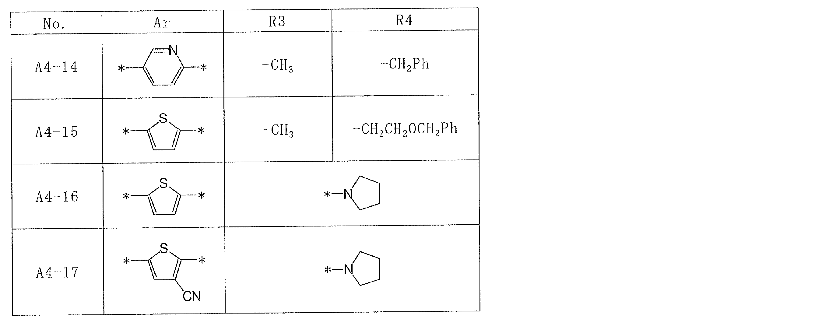
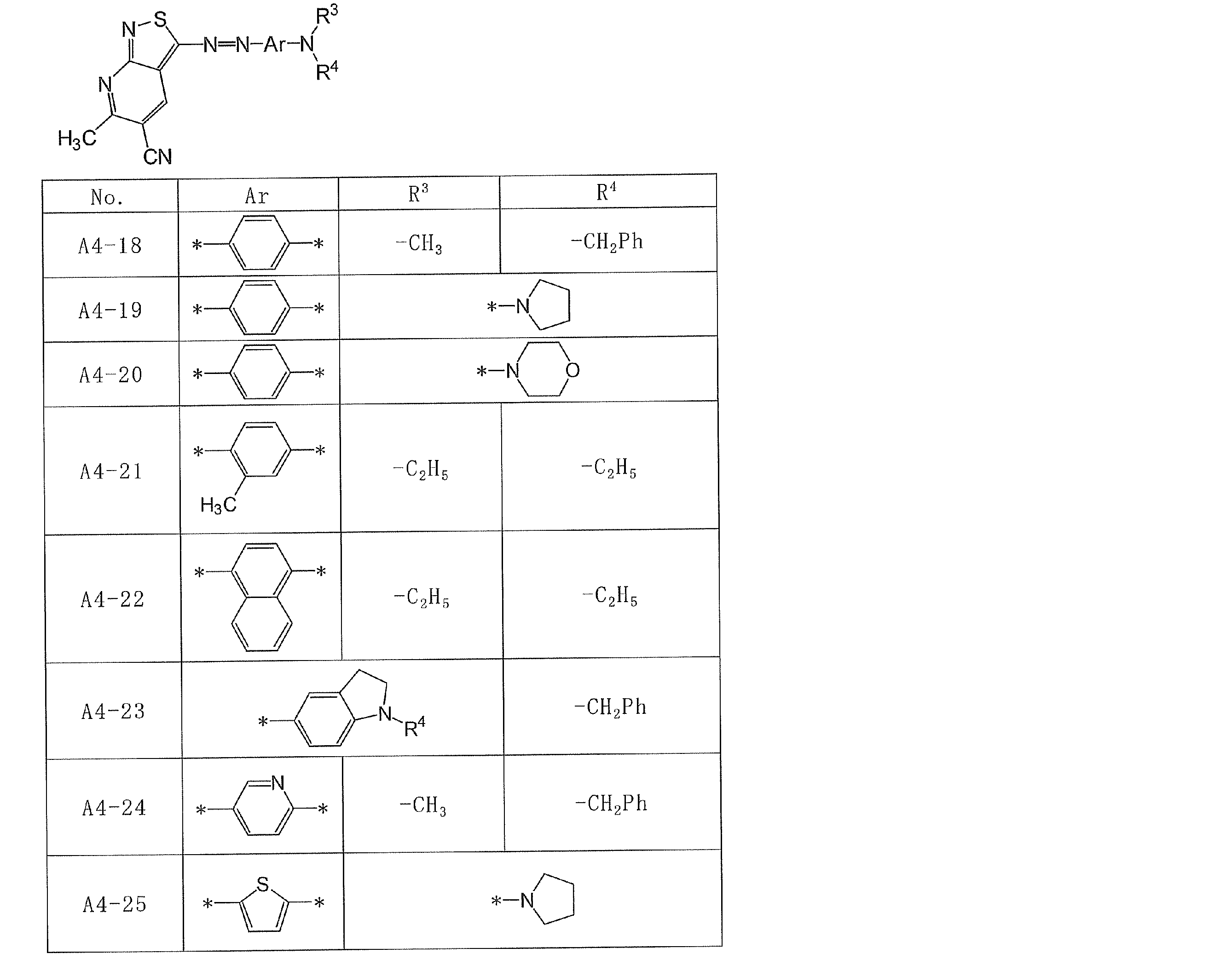

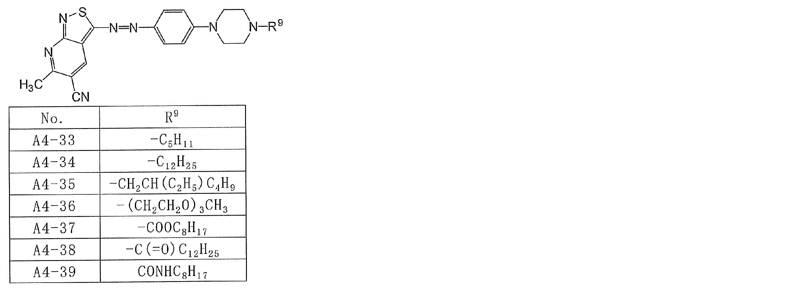


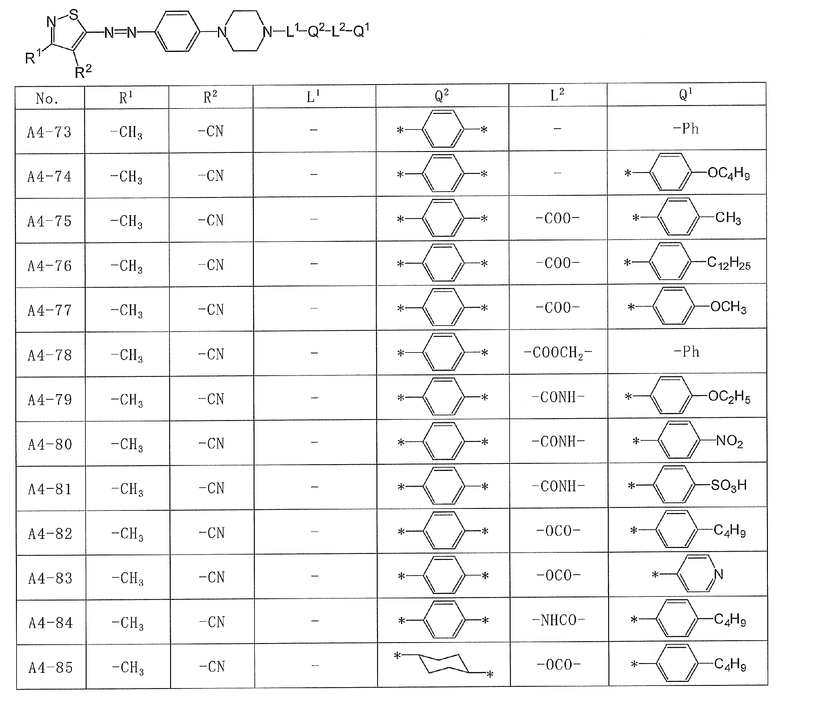

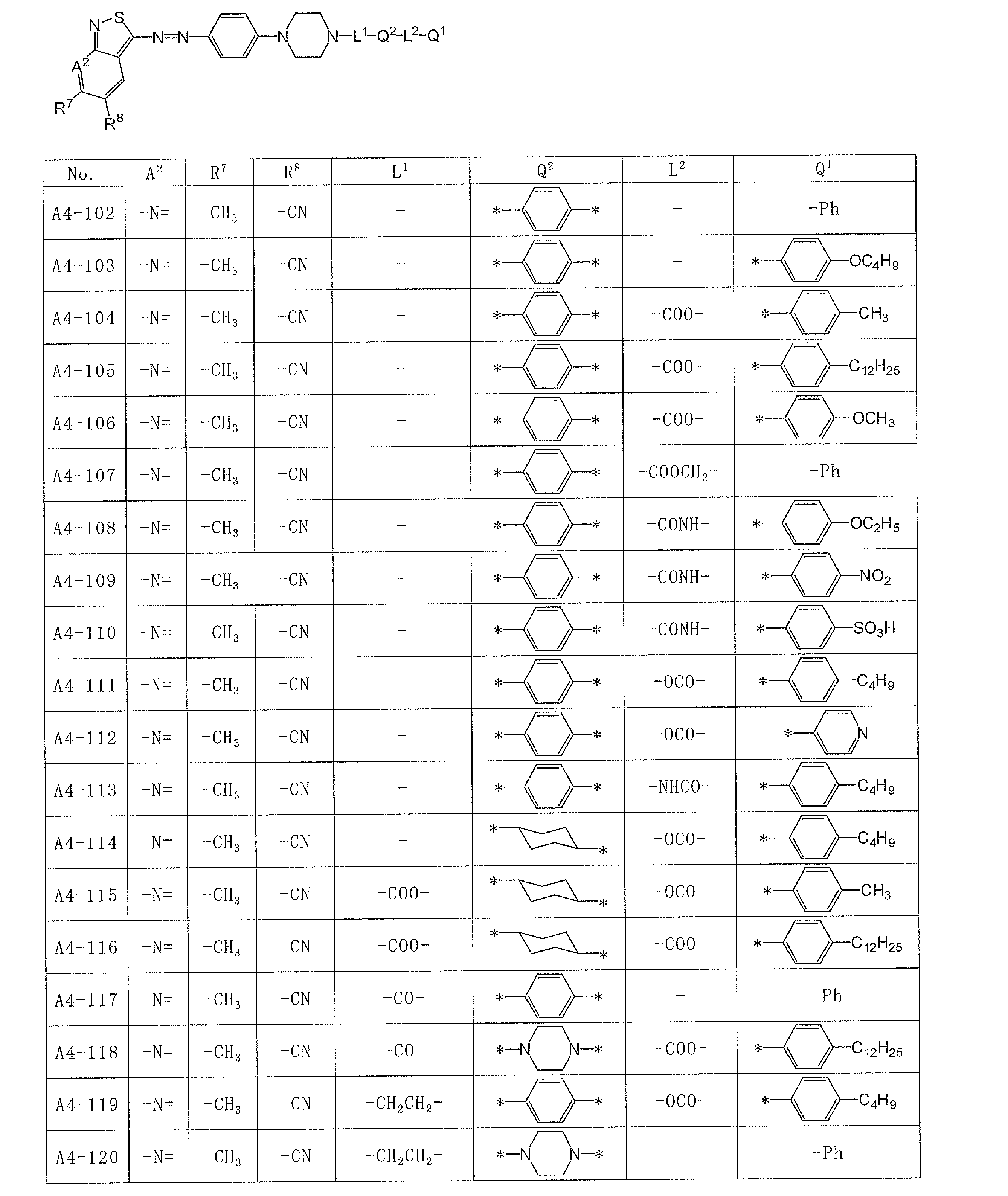

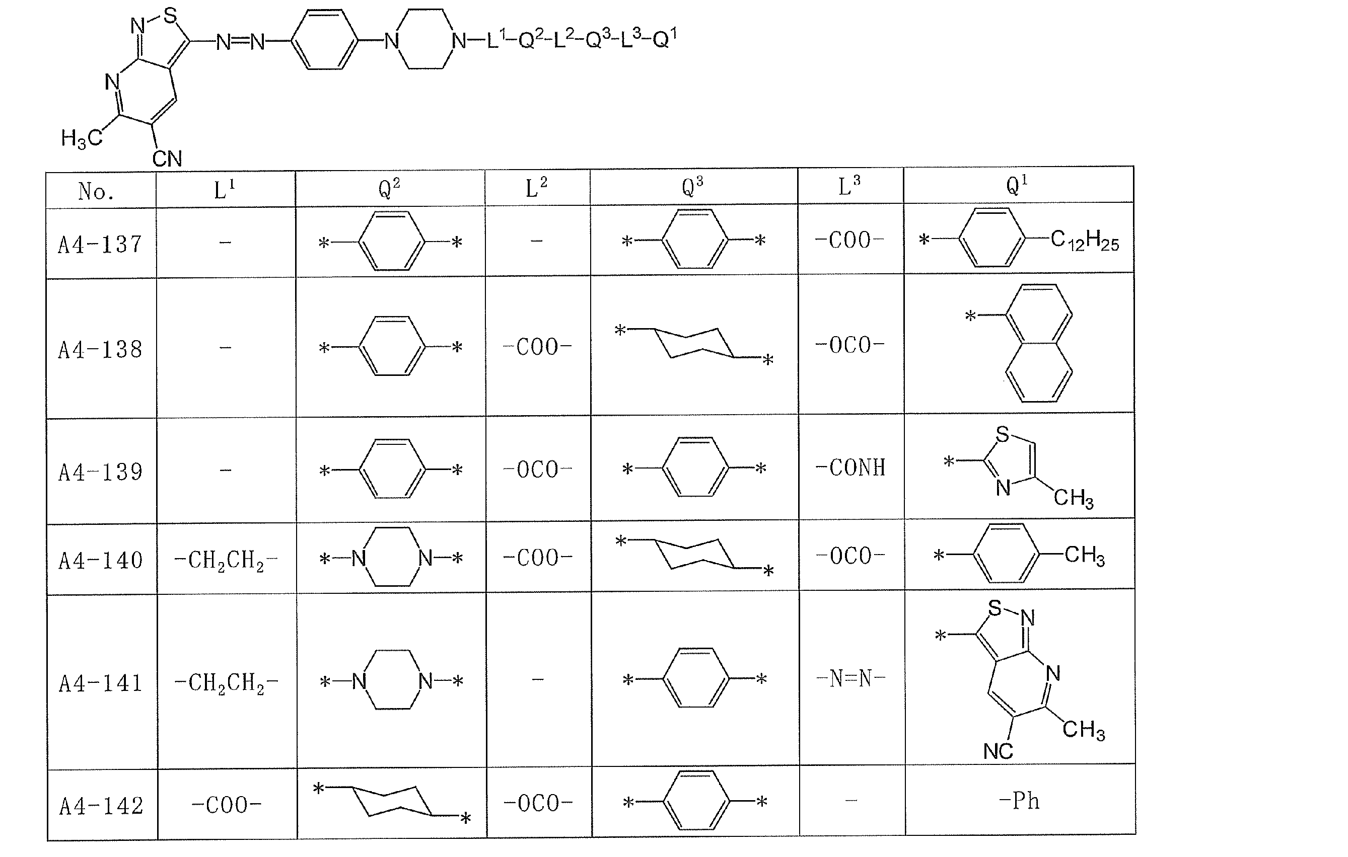
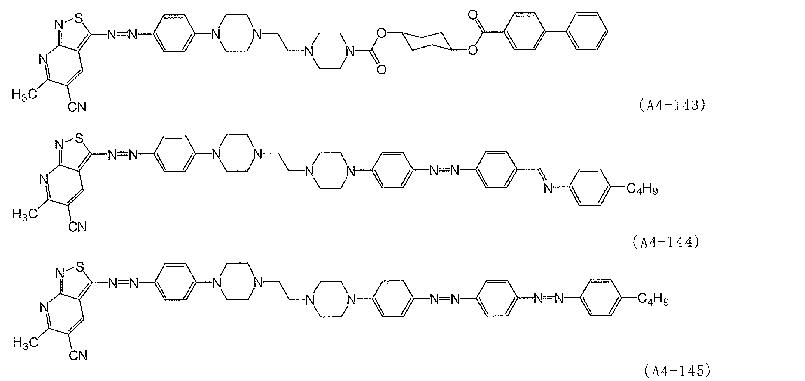
前記一般式(I)、(II)、(III)、又は(IV)で表される化合物(アゾ色素)は、「Dichroic Dyes for Liquid Crystal Display」(A. V. Ivashchenko著、CRC社、1994年)、「総説合成染料」(堀口博著、三共出版、1968年)及びこれらに引用されている文献に記載の方法を参考にして合成することができる。
また、本発明における前記一般式(I)、(II)、(III)、又は(IV)で表されるアゾ色素は、Journal of Materials Chemistry (1999), 9(11), 2755-2763等に記載の方法に準じて容易に合成することができる。
また、本発明における前記一般式(I)、(II)、(III)、又は(IV)で表されるアゾ色素は、Journal of Materials Chemistry (1999), 9(11), 2755-2763等に記載の方法に準じて容易に合成することができる。
前記一般式(I)、(II)、(III)、又は(IV)で表されるアゾ色素は、その分子構造から明らかなように、分子形状が平板で直線性がよく、剛直なコア部分と柔軟な側鎖部分を有しており、且つアゾ色素の分子長軸末端に極性なアミノ基を有するため、それ自身液晶性、特にネマチック液晶性を発現しやすい性質を有しているという特徴を有する。
このようにして、本発明において、上記(I)、(II)、(III)、又は(IV)で表される二色性色素の少なくとも一種を含有する二色性色素組成物は、液晶性を有するものとなる。
さらに、前記一般式(I)、(II)、(III)、又は(IV)で表されるアゾ色素は、分子の平面性が高いため強い分子間相互作用が働き、分子同士が会合状態を形成しやすい性質も有している。
このようにして、本発明において、上記(I)、(II)、(III)、又は(IV)で表される二色性色素の少なくとも一種を含有する二色性色素組成物は、液晶性を有するものとなる。
さらに、前記一般式(I)、(II)、(III)、又は(IV)で表されるアゾ色素は、分子の平面性が高いため強い分子間相互作用が働き、分子同士が会合状態を形成しやすい性質も有している。
前記一般式(I)、(II)、(III)、又は(IV)で表されるアゾ色素を含有する二色性色素組成物は、会合形成により可視の広い波長領域において高い吸光度を表すということだけでなく、この色素を含有した組成物が、具体的にはネマチック液晶性を有するため、例えば、ラビングしたポリビニルアルコール配向膜表面への塗布などの積層プロセスを経ることによって、高次の分子配向状態を実現できる。したがって、前記一般式(I)、(II)、(III)、又は(IV)で表されるアゾ色素を含有する二色性色素組成物から形成された直線偏光層は偏光特性が高く、それを有する印画紙は、クロストークやゴースト像のない鮮明な立体画像を提供することができる。
前記二色性色素組成物の好ましい(D)は18以上である。
前記二色性色素組成物の好ましい(D)は18以上である。
前記一般式(I)、(II)、(III)、又は(IV)で表されるアゾ色素の液晶性については、好ましくは10~300℃、より好ましくは100~250℃でネマチック液晶相を示す。
前記二色性色素組成物は一般式(I)、(II)、(III)、又は(IV)で表されるアゾ色素を1種以上含有することが好ましい。高い二色比の直線偏光層とするためには、黒色の二色性色素組成物から形成することが好ましい。なお、前記一般式(Ia)で表わされるアゾ色素は、マゼンタのアゾ色素であり、一般式(Ib)及び(II)で表わされるアゾ色素は、イエロー又はマゼンタのアゾ色素であり、一般式(III)及び(IV)で表わされるアゾ色素は、シアンのアゾ色素である。これらを混合することで黒色の組成物を調製してもよい。
なお、前記二色性色素は、一般式(I)、(II)、(III)、又は(IV)で表されるアゾ色素以外の色素であってもよい。一般式(I)、(II)、(III)、又は(IV)で表されるアゾ色素以外の色素も、液晶性を示す化合物から選択されるのが好ましい。このような色素としては、例えば、シアニン系色素、アゾ金属錯体、フタロシアニン系色素、ピリリウム系色素、チオピリリウム系色素、アズレニウム系色素、スクアリリウム系色素、キノン系色素、トリフェニルメタン系色素、及びトリアリルメタン系色素等を挙げることができる。好ましくは、スクアリリウム系色素である。特に、「Dichroic Dyes for Liquid Crystal Display」(A. V. Ivashchenko著、CRC社、1994年)に記載のものも用いることができる。
本発明に使用可能なスクアリリウム系色素は、下記一般式(VI)で表されることが特に好ましい。

式中、A1及びA2はそれぞれ独立に、置換もしくは無置換の、炭化水素環基又は複素環基を表わす。
炭化水素環基は、5~20員の単環又は縮合環の基であるのが好ましい。炭化水素環基は、芳香族環であっても、非芳香族環であってもよい。炭化水素環を構成している炭素原子は、水素原子以外の原子で置換されていてもよい。例えば、炭化水素環を構成している1以上の炭素原子は、C=O、C=S又はC=NR(Rは水素原子又はC1-10のアルキル基)であってもよい。また、炭化水素環を構成している1以上の炭素原子は、置換基を有していてもよく、置換基の具体例については、後述する置換基群Gから選択することができる。前記炭化水素環基の例には、以下の基が含まれるが、これらに限定されるものではない。
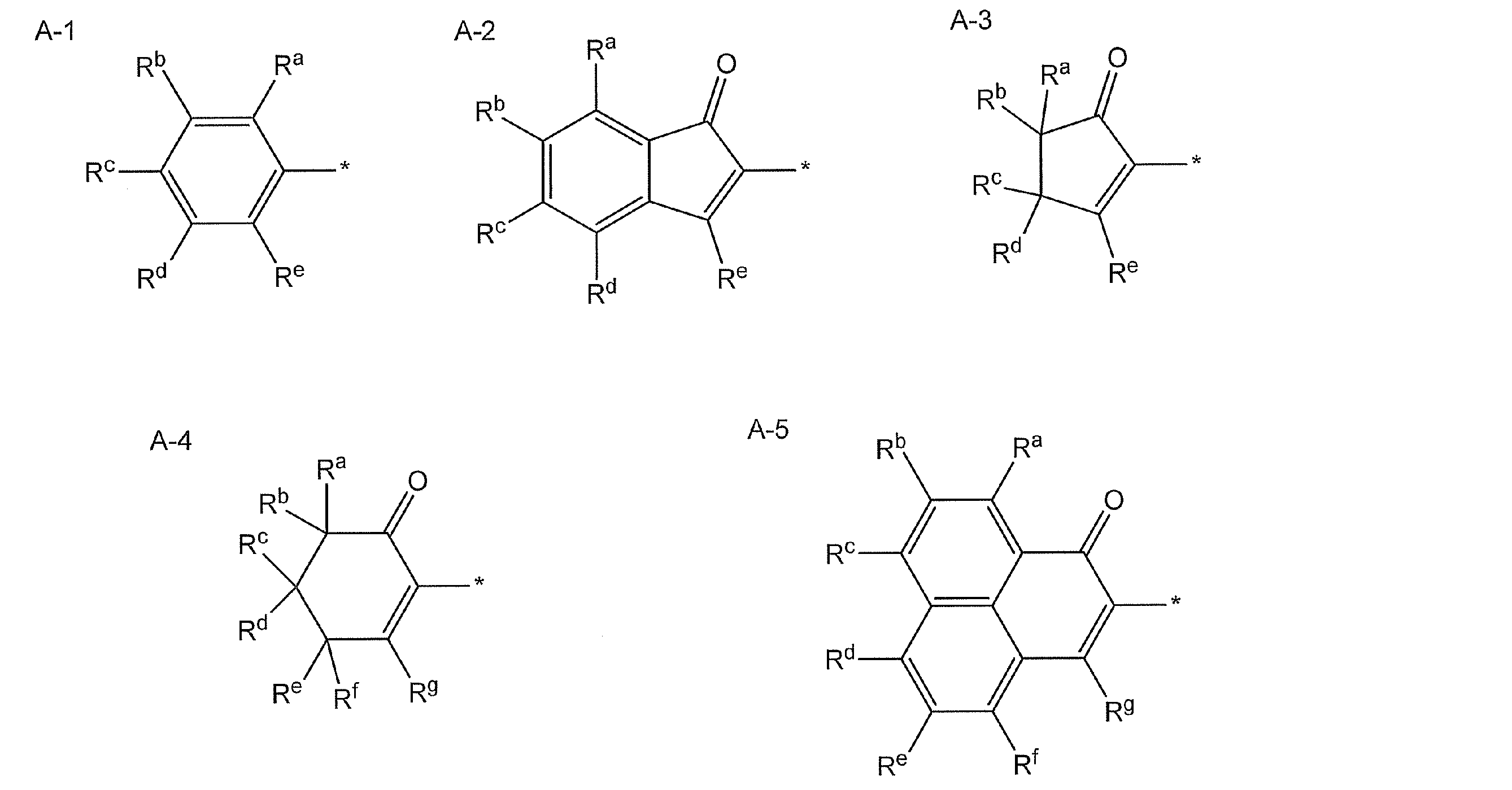
上記式中、*は、スクアリウム骨格に結合する部位を示し、Ra~Rgはそれぞれ水素原子又は置換基を表し、可能であれば互いに結合して環構造を形成していてもよい。該置換基は、後述する置換基群Gから選択することができる。
特に、以下の例が好ましい。
式A-1中、Rcは-N(Rc1)(Rc2)であり、Rc1及びRc2はそれぞれ、水素原子、又は置換もしくは無置換の炭素数1~10の置換もしくは無置換のアルキル基を表わし、Rb及びRdが水素原子であり、即ち、下記式A-1aで表される基である。
式A-2中、Reがヒドロキシ基であり、即ち、下記式A-2aで表される基である。
式A-3中、Reがヒドロキシ基であり、Rc及びRdが水素原子であり、即ち、下記式A-3aで表される基である。
式A-4中、Rgがヒドロキシ基であり、Ra、Rb、Re及びRfが水素原子であり、即ち、下記式A-4aで表される基である。
式A-5中、Rgがヒドロキシ基であり、即ち、下記式A-5aで表される基である。
特に、以下の例が好ましい。
式A-1中、Rcは-N(Rc1)(Rc2)であり、Rc1及びRc2はそれぞれ、水素原子、又は置換もしくは無置換の炭素数1~10の置換もしくは無置換のアルキル基を表わし、Rb及びRdが水素原子であり、即ち、下記式A-1aで表される基である。
式A-2中、Reがヒドロキシ基であり、即ち、下記式A-2aで表される基である。
式A-3中、Reがヒドロキシ基であり、Rc及びRdが水素原子であり、即ち、下記式A-3aで表される基である。
式A-4中、Rgがヒドロキシ基であり、Ra、Rb、Re及びRfが水素原子であり、即ち、下記式A-4aで表される基である。
式A-5中、Rgがヒドロキシ基であり、即ち、下記式A-5aで表される基である。

上記式A-1a中、Rc1及びRc2は各々独立に、水素原子又は炭素数1~10の置換もしくは無置換のアルキル基を表わし;上記式中のその他の記号は、上記式A-1~A-5中のそれぞれと同義である。アルキル基の置換基の例としては、後述の置換基群Gが挙げられ、好ましい範囲も同様である。Rc1及びRc2が、置換もしくは無置換のアルキル基である場合、互いに連結して、含窒素複素環基を形成してもよい。また、Rc1及びRc2の少なくとも一方が、式A-1a中のベンゼン環の炭素原子と結合して、縮合環を形成していてもよい。例えば、以下の式A-1b及びA-1cであってもよい。

式中、*は、スクアリウム骨格に結合する部位を示し、Rhは、水素原子又は置換基を表す。該置換基の例には、後述の置換基群Gが含まれる。Rhは、ベンゼン環を1以上含む置換基であるのが好ましい。
複素環基は、5~20員の単環又は縮合環の基であるのが好ましい。複素環基は、窒素原子、硫黄原子、及び酸素原子の少なくとも1つを環構成原子として有する。また、環構成原子として1以上の炭素原子を含んでいてもよく、複素環を構成している、ヘテロ原子又は炭素原子は、水素原子以外の原子で置換されていてもよい。例えば、複素環を構成している1以上の硫黄原子は、例えば、S=O又はS(O)2であってもよく、また複素環を構成している1以上の炭素原子は、C=O、C=S又はC=NR(Rは水素原子又はC1-10のアルキル基)であってもよい。また、複素環基は、芳香族環であっても、非芳香族環であってもよい。複素環基を構成している1以上のヘテロ原子及び/又は炭素原子は、置換基を有していてもよく、置換基の具体例については、後述する置換基群Gから選択することができる。前記複素環基の例には、以下の基が含まれるが、これらに限定されるものではない。

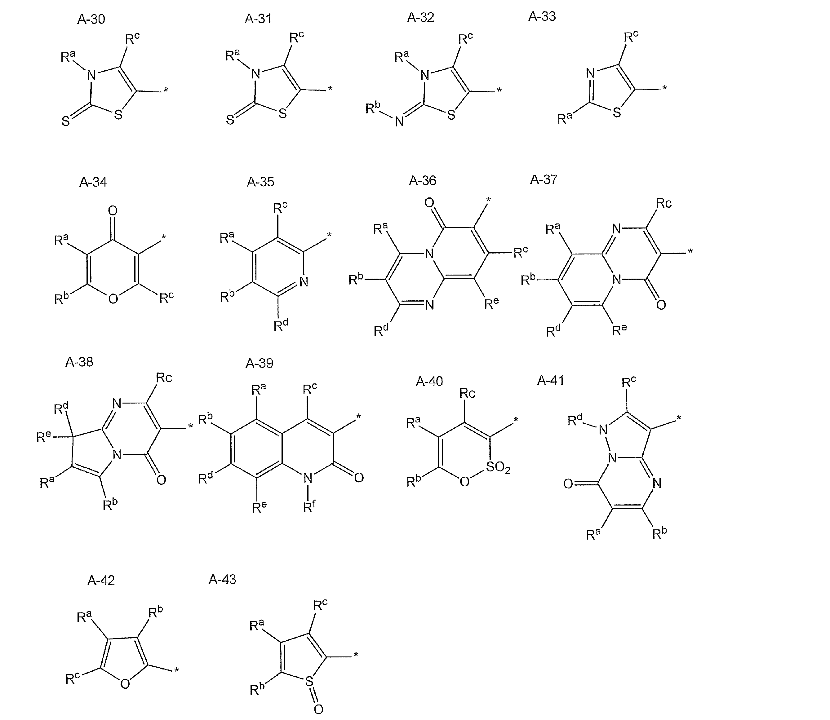
上記式中、*は、スクアリウム骨格に結合する部位を示し、Ra~Rfはそれぞれ水素原子又は置換基を表し、可能であれば互いに結合して環構造を形成していてもよい。該置換基は、後述する置換基群Gから選択することができる。
A-6~A-43中、Rcはヒドロキシ基(OH)又はヒドロチオキシ基(SH)であるのが好ましい。
A-6~A-43中、Rcはヒドロキシ基(OH)又はヒドロチオキシ基(SH)であるのが好ましい。
好ましい炭化水素環基は、A-1、A-2、及びA-4で表される炭化水素環基である。より好ましくは、A-1a、A-2a及びA-4aである。特に好ましくは、A-1及びA-2で表される炭化水素環基であり、より好ましくはA-1a及びA-2aである。さらに好ましくは、A-1aであり、中でも、Ra及びReが水素原子又は水酸基を表わすA-1aで表される炭化水素環基である。
好ましい複素環基は、A-6、A-7、A-8、A-9、A-10、A-11、A-14、A-24、A-34、A-37及びA-39で示される複素環である。特に好ましくは、A-6、A-7、A-8、A-9、A-11、A-14、A-34及びA-39で示される複素環である。これらの式中、Rcはヒドロキシ基(OH)又はヒドロチオキシ基(SH)であるのがより好ましい。
前記式(VI)中、A1及びA2の少なくとも一方が、A-1(より好ましくはA-1a)であることが特に好ましい。
前記炭化水素環基及び複素環基は1以上の置換基を有していてもよく、該置換基の例としては、下記の置換基群Gが含まれる。
置換基群G:
炭素数1~18(好ましくは炭素数1~8)の置換もしくは無置換の直鎖状、分岐鎖状又は環状のアルキル基(例、メチル、エチル、プロピル、イソプロピル、n-ブチル、イソブチル、sec-ブチル、t-ブチル、シクロヘキシル、メトキシエチル、エトキシカルボニルエチル、シアノエチル、ジエチルアミノエチル、ヒドロキシエチル、クロロエチル、アセトキシエチル、トリフルオロメチル等);炭素数7~18(好ましくは炭素数7~12)の置換もしくは無置換のアラルキル基(例、ベンジル、カルボキシベンジル等);炭素数2~18(好ましくは炭素数2~8)の置換もしくは無置換のアルケニル基(例、ビニル等);炭素数2~18(好ましくは炭素数2~8)の置換もしくは無置換のアルキニル基(例、エチニル等);炭素数6~18(好ましくは炭素数6~10)の置換もしくは無置換のアリール基(例、フェニル、4-メチルフェニル、4-メトキシフェニル、4-カルボキシフェニル、3、5-ジカルボキシフェニル等);
置換基群G:
炭素数1~18(好ましくは炭素数1~8)の置換もしくは無置換の直鎖状、分岐鎖状又は環状のアルキル基(例、メチル、エチル、プロピル、イソプロピル、n-ブチル、イソブチル、sec-ブチル、t-ブチル、シクロヘキシル、メトキシエチル、エトキシカルボニルエチル、シアノエチル、ジエチルアミノエチル、ヒドロキシエチル、クロロエチル、アセトキシエチル、トリフルオロメチル等);炭素数7~18(好ましくは炭素数7~12)の置換もしくは無置換のアラルキル基(例、ベンジル、カルボキシベンジル等);炭素数2~18(好ましくは炭素数2~8)の置換もしくは無置換のアルケニル基(例、ビニル等);炭素数2~18(好ましくは炭素数2~8)の置換もしくは無置換のアルキニル基(例、エチニル等);炭素数6~18(好ましくは炭素数6~10)の置換もしくは無置換のアリール基(例、フェニル、4-メチルフェニル、4-メトキシフェニル、4-カルボキシフェニル、3、5-ジカルボキシフェニル等);
炭素数2~18(好ましくは炭素数2~8)の置換もしくは無置換のアシル基(例、アセチル、プロピオニル、ブタノイル、クロロアセチル等);炭素数1~18(好ましくは炭素数1~8)の置換もしくは無置換のアルキル又はアリールスルホニル基(例、メタンスルホニル、p-トルエンスルホニル等);炭素数1~18(好ましくは炭素数1~8)のアルキルスルフィニル基(例、メタンスルフィニル、エタンスルフィニル、オクタンスルフィニル等);炭素数2~18(好ましくは炭素数2~8)のアルコキシカルボニル基(例、メトキシカルボニル、エトキシカルボニル等);炭素数7~18(好ましくは炭素数7~12)のアリールオキシカルボニル基(例、フェノキシカルボニル、4-メチルフェノキシカルボニル、4-メトキシフェニルカルボニル等);炭素数1~18(好ましくは炭素数1~8)の置換もしくは無置換のアルコキシ基(例えば、メトキシ、エトキシ、n-ブトキシ、メトキシエトキシ等);炭素数6~18(好ましくは炭素数6~10)の置換もしくは無置換のアリールオキシ基(例、フェノキシ、4-メトキシフェノキシ等);炭素数1~18(好ましくは炭素数1~8)のアルキルチオ基(例、メチルチオ、エチルチオ等);炭素数6~10のアリールチオ基(例、フェニルチオ等);
炭素数2~18(好ましくは炭素数2~8)の置換もしくは無置換のアシルオキシ基(例、アセトキシ、エチルカルボニルオキシ、シクロヘキシルカルボニルキシ、ベンゾイルオキシ、クロロアセチルオキシ等);炭素数1~18(好ましくは炭素数1~8)の置換もしくは無置換のスルホニルオキシ基(例、メタンスルホニルオキシ等);炭素数2~18(好ましくは炭素数2~8)の置換もしくは無置換のカルバモイルオキシ基(例、メチルカルバモイルオキシ、ジエチルカルバモイルオキシ等);無置換のアミノ基又は炭素数1~18(好ましくは炭素数1~8)の置換アミノ基(例、メチルアミノ、ジメチルアミノ、ジエチルアミノ、アニリノ、メトキシフェニルアミノ、クロロフェニルアミノ、モルホリノ、ピペリジノ、ピロリジノ、ピリジルアミノ、メトキシカルボニルアミノ、n-ブトキシカルボニルアミノ、フェノキシカルボニルアミノ、メチルカルバモイルアミノ、フェニルカルバモイルアミノ、エチルチオカルバモイルアミノ、メチルスルファモイルアミノ、フェニルスルファモイルアミノ、アセチルアミノ、エチルカルボニルアミノ、エチルチオカルボニルアミノ、シクロヘキシルカルボニルアミノ、ベンゾイルアミノ、クロロアセチルアミノ、メタンスルホニルアミノ、ベンゼンスルホニルアミノ等);
炭素数1~18(好ましくは炭素数1~8)の置換もしくは無置換のカルバモイル基(例、無置換のカルバモイル、メチルカルバモイル、エチルカルバモイル、n-ブチルカルバモイル、t-ブチルカルバモイル、ジメチルカルバモイル、モルホリノカルバモイル、ピロリジノカルバモイル等);無置換のスルファモイル基、炭素数1~18(好ましくは炭素数1~8)の置換スルファモイル基(例、メチルスルファモイル、フェニルスルファモイル等);ハロゲン原子(例、フッ素、塩素、臭素等);水酸基;ニトロ基;シアノ基;カルボキシル基;ヘテロ環基(例、オキサゾール、ベンゾオキサゾール、チアゾール、ベンゾチアゾール、イミダゾール、ベンゾイミダゾール、インドレニン、ピリジン、スルホラン、フラン、チオフェン、ピラゾール、ピロール、クロマン、クマリンなど)。
式(VI)で表される二色性スクアリウム色素の例には、以下の例示化合物が含まれるが、これらに限定されるものではない。


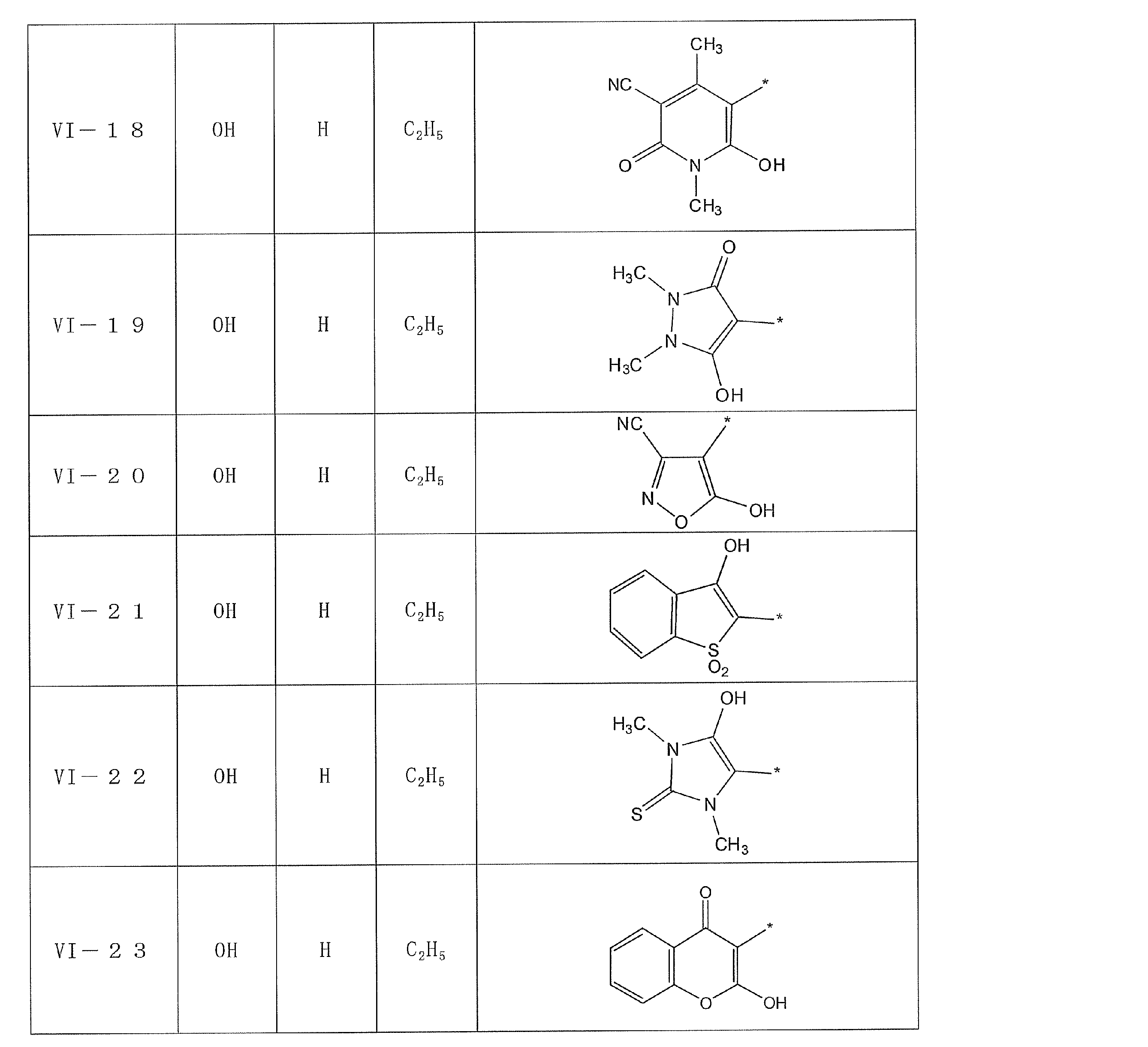
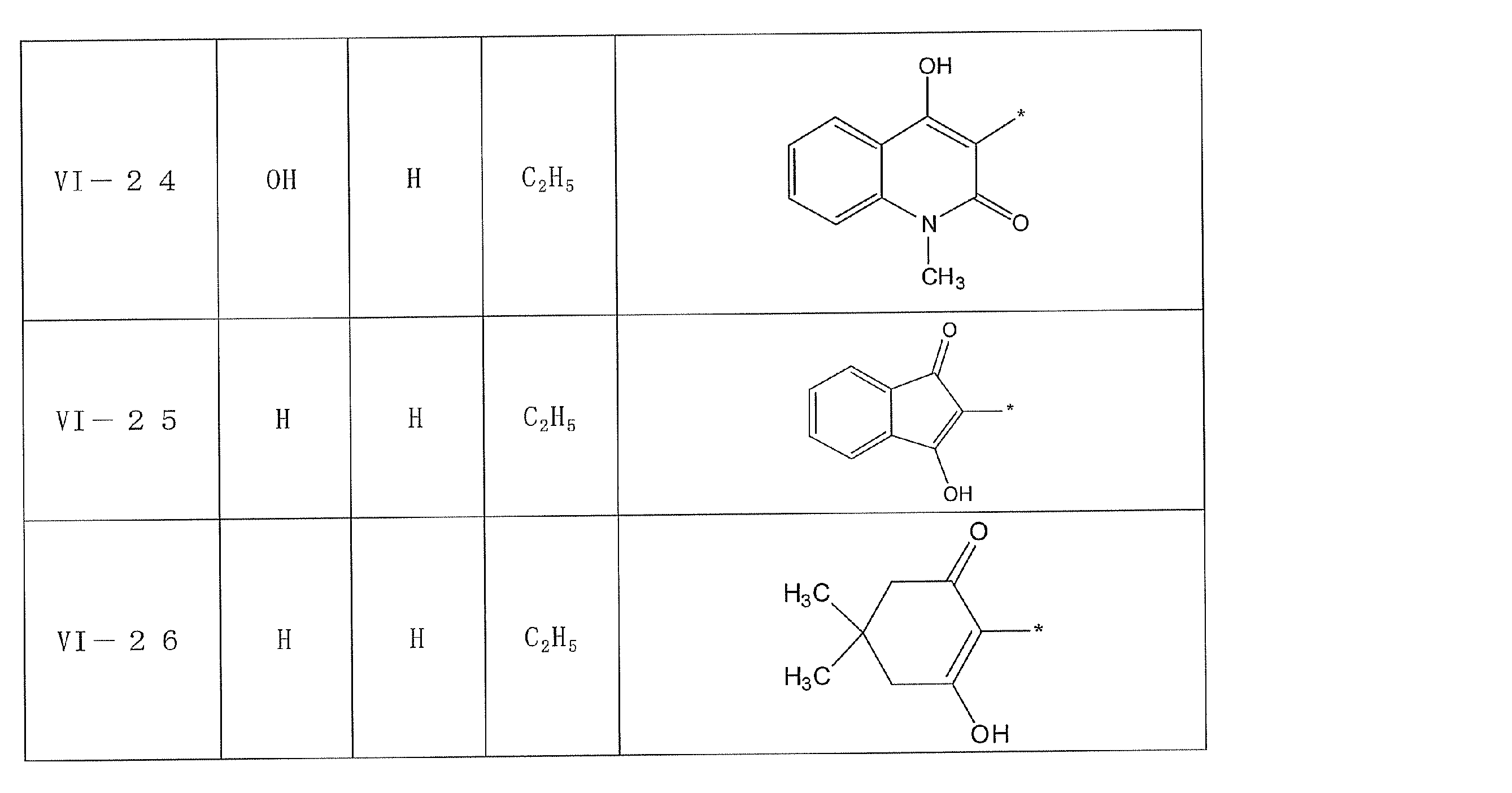
前記一般式(VI)で表され二色性スクアリリウム色素は、Journal of Chemical Society, Perkin Trans. 1 (2000), 599-603、 Synthesis (2002), No.3, 413-417等に記載の方法に準じて容易に合成することができる。
本発明に使用する二色性色素は、遷移モーメントと分子長軸のなす角度が0度以上20度以下であることが好ましく、より好ましくは0度以上15度以下であり、さらに好ましくは0度以上10度以下であり、特に好ましくは0度以上5度以下である。ここで分子長軸とは、化合物中で原子間距離が最大となる2つの原子を結ぶ軸を言う。遷移モーメントの方向は分子軌道計算により求めることができ、そこから分子長軸となす角度も計算することができる。
本発明に使用する二色性色素は、剛直な直線状の構造であることが好ましい。具体的には、分子長は好ましくは17Å以上であり、より好ましくは20Å以上であり、さらに好ましくは25Å以上である。また、アスペクト比は好ましくは1.7以上であり、より好ましくは2以上であり、さらに好ましくは2.5以上である。これによって良好な一軸配向が達成され、偏光性能の高い二色性色素層及び立体画像印刷物を得ることができる。
ここで分子長とは、化合物中で最大の原子間距離に両端の2原子のファンデルワールス半径を加えた値である。アスペクト比とは分子長/分子幅であり、分子幅とは、分子長軸に垂直な面に各原子を投影したときの最大の原子間距離に両端の2原子のファンデルワールス半径を加えた値である。
ここで分子長とは、化合物中で最大の原子間距離に両端の2原子のファンデルワールス半径を加えた値である。アスペクト比とは分子長/分子幅であり、分子幅とは、分子長軸に垂直な面に各原子を投影したときの最大の原子間距離に両端の2原子のファンデルワールス半径を加えた値である。
前記二色性色素組成物は、1種以上の前記一般式(I)、(II)、(III)、(IV)、又は(VI)で表される色素を主成分として含有する。具体的には、前記一般式(I)、(II)、(III)、(IV)、又は(VI)で表される色素の含有量は、含有される全色素の合計の含有量に対して、80質量%以上であることが好ましく、90質量%以上であることが特に好ましい。上限値は100質量%であり、即ち、含有される色素が全て、一般式(I)、(II)、(III)、(IV)、又は(VI)で表される色素であっても勿論よい。
また、前記二色性色素組成物に含まれる、溶剤を除く全固形分において、1種以上の一般式(I)、(II)、(III)、(IV)、又は(VI)で表される二色性色素の含有量は、20質量%以上であることが好ましく、30質量%以上であることが特に好ましい。上限値は特に制限されないが、下記の界面活性剤等、他の添加剤を含有する態様では、それらの効果を得るためには、前記二色性色素組成物に含まれる、溶剤を除く全固形分における、1種以上の一般式(I)、(II)、(III)、(IV)、又は(VI)で表される二色性色素の含有量は、95質量%以下であるのが好ましく、90質量%以下であるのがより好ましい。
前記二色性色素組成物は、サーモトロピック液晶性、即ち、熱によって液晶相に転移して、液晶性を示すのが好ましい。好ましくは10~300℃、より好ましくは100~250℃でネマチック液晶相を示す。特に、ネマチック液晶相より低温領域にスメクチックA液晶相を示すことが好ましく、その好ましい温度範囲は、10~200℃、より好ましくは50~200℃である。
前記二色性色素組成物の塗布液を配向膜上に適用すると、二色性色素は配向膜との界面では配向膜のチルト角で配向し、空気との界面では空気界面のチルト角で配向する。本発明の二色性色素組成物塗布液を配向膜の表面に塗布後、二色性色素を均一配向(モノドメイン配向)させることで、水平配向を実現することができる。
二色性色素を水平配向させ、且つその配向状態に固定することによって形成された二色性色素層は、立体画像印刷物として利用することができる。
二色性色素を水平配向させ、且つその配向状態に固定することによって形成された二色性色素層は、立体画像印刷物として利用することができる。
本発明において、チルト角とは、二色性色素の分子の長軸方向と界面(配向膜界面あるいは空気界面)のなす角度を指す。配向膜側のチルト角を有る程度小さくし水平配向させることが高い二色比の直線偏光層となるので好ましい。好ましい配向膜側のチルト角は0°~10°、さらに好ましくは0°~5°、特に好ましいのは0°~2°、最も好ましくは0°~1°である。また、好ましい空気界面側のチルト角は0°~10°、さらに好ましくは0~5°、特に好ましいのは0~2°である。
一般的に、空気界面側の二色性色素のチルト角は、所望により添加される他の化合物(例えば、特開2005-99248号公報、特開2005-134884号公報、特開2006-126768号公報、特開2006-267183号公報記載の水平配向化剤など)を選択することにより調整することができ、好ましい水平配向状態を実現することができる。
また、配向膜側の二色性色素のチルト角は、配向膜チルト角制御剤等により制御することができる。
また、配向膜側の二色性色素のチルト角は、配向膜チルト角制御剤等により制御することができる。
前記二色性色素組成物は、上記二色性色素以外に、1種以上の添加剤を含有していてもよい。前記二色性色素組成物は、ラジカル重合性基を有する非液晶性の多官能モノマー、重合開始剤、風ムラ防止剤、ハジキ防止剤、糖類、防黴、抗菌及び殺菌の少なくともいずれかの機能を有する薬剤等を含有していてもよい。
[配向膜]
前記直線偏光層を、二色性色素を含有する液晶性組成物から形成する態様では、該直線偏光層の製造には、配向膜を利用するのが好ましい。利用可能な配向膜は、当該配向膜上で、二色性色素の分子を所望の配向状態とすることができるのであれば、どのような層でもよい。有機化合物(好ましくはポリマー)の膜表面へのラビング処理、無機化合物の斜方蒸着、マイクログルーブを有する層の形成、あるいはラングミュア・ブロジェット法(LB膜)による有機化合物(例、ω-トリコサン酸、ジオクタデシルメチルアンモニウムクロライド、ステアリル酸メチル)の累積のような手段で、設けることができる。さらに、電場の付与、磁場の付与あるいは光照射により、配向機能が生じる配向膜も知られている。中でも、本発明では、配向膜のプレチルト角の制御し易さの点からはラビング処理により形成するラビング配向膜が好ましく、配向の均一性の点からは光照射により形成する光配向膜が好ましい。ラビング配向膜の材料として、ポリビニルアルコール及びポリイミドなどが一般的である。また、光配向膜については、後述する位相差層の形成に利用可能な配向膜の例と同様である。
前記直線偏光層を、二色性色素を含有する液晶性組成物から形成する態様では、該直線偏光層の製造には、配向膜を利用するのが好ましい。利用可能な配向膜は、当該配向膜上で、二色性色素の分子を所望の配向状態とすることができるのであれば、どのような層でもよい。有機化合物(好ましくはポリマー)の膜表面へのラビング処理、無機化合物の斜方蒸着、マイクログルーブを有する層の形成、あるいはラングミュア・ブロジェット法(LB膜)による有機化合物(例、ω-トリコサン酸、ジオクタデシルメチルアンモニウムクロライド、ステアリル酸メチル)の累積のような手段で、設けることができる。さらに、電場の付与、磁場の付与あるいは光照射により、配向機能が生じる配向膜も知られている。中でも、本発明では、配向膜のプレチルト角の制御し易さの点からはラビング処理により形成するラビング配向膜が好ましく、配向の均一性の点からは光照射により形成する光配向膜が好ましい。ラビング配向膜の材料として、ポリビニルアルコール及びポリイミドなどが一般的である。また、光配向膜については、後述する位相差層の形成に利用可能な配向膜の例と同様である。
直線偏光層の保護層:
前記直線偏光層は、その両面に、保護層を有していてもよい。保護層には、光透過性の高分子フィルムを用いることができる。但し、上記した通り、位相差層との間に配置される層の光学特性は、観察者の眼に入射する円偏光画像の偏光状態に影響を与えるので、低位相差であることが好ましく、位相差は0か実質的に0に等しいフィルムであるのが好ましい。具体的には、位相差層と直線偏光層との間に配置される保護層のReは、0~10nmであるのが好ましい。また、厚み方向のレターデーションRthも、円偏光画像の偏光状態に影響を与えるので、位相差層と直線偏光層との間に配置される保護層のRthも低いのが好ましく、該保護層及び前記位相差層の、Rthの合計の絶対値が、20nm以下であることが好ましい。
前記直線偏光層は、その両面に、保護層を有していてもよい。保護層には、光透過性の高分子フィルムを用いることができる。但し、上記した通り、位相差層との間に配置される層の光学特性は、観察者の眼に入射する円偏光画像の偏光状態に影響を与えるので、低位相差であることが好ましく、位相差は0か実質的に0に等しいフィルムであるのが好ましい。具体的には、位相差層と直線偏光層との間に配置される保護層のReは、0~10nmであるのが好ましい。また、厚み方向のレターデーションRthも、円偏光画像の偏光状態に影響を与えるので、位相差層と直線偏光層との間に配置される保護層のRthも低いのが好ましく、該保護層及び前記位相差層の、Rthの合計の絶対値が、20nm以下であることが好ましい。
前記保護層として用いる高分子フィルムの材料については、特に制限はない。光学性能透明性、機械的強度、熱安定性、水分遮蔽性、等方性などに優れるポリマーが好ましく、上述の光学特性を満足するフィルムを形成可能な材料であれば、いずれも用いることができる。例えば、ポリカーボネート系ポリマー、ポリエチレンテレフタレートやポリエチレンナフタレート等のポリエステル系ポリマー、ポリメチルメタクリレート等のアクリル系ポリマー、ポリスチレンやアクリロニトリル・スチレン共重合体(AS樹脂)等のスチレン系ポリマーなどがあげられる。また、ポリエチレン、ポリプロピレン等のポリオレフィン、エチレン・プロピレン共重合体の如きポリオレフィン系ポリマー、塩化ビニル系ポリマー、ナイロンや芳香族ポリアミド等のアミド系ポリマー、イミド系ポリマー、スルホン系ポリマー、ポリエーテルスルホン系ポリマー、ポリエーテルエーテルケトン系ポリマー、ポリフェニレンスルフィド系ポリマー、塩化ビニリデン系ポリマー、ビニルアルコール系ポリマー、ビニルブチラール系ポリマー、アリレート系ポリマー、ポリオキシメチレン系ポリマー、エポキシ系ポリマー、又は前記ポリマーを混合したポリマーも例としてあげられる。また本発明の高分子フィルムは、アクリル系、ウレタン系、アクリルウレタン系、エポキシ系、シリコーン系等の紫外線硬化型、熱硬化型の樹脂の硬化層として形成することもできる。
また、前記保護層の材料としては、熱可塑性ノルボルネン系樹脂を好ましく用いることが出来る。熱可塑性ノルボルネン系樹脂としては、日本ゼオン(株)製のゼオネックス、ゼオノア、JSR(株)製のアートン等があげられる。
また、前記保護層として用いられるフィルムを形成する材料としては、従来偏光板の透明保護フィルムとして用いられてきた、トリアセチルセルロースに代表される、セルロース系ポリマー(以下、セルロースアシレートという)を好ましく用いることができる。以下に、前記保護層として使用可能なセルロースアシレート系フィルムについて詳細に説明するが、その技術的事項は、他の高分子フィルムについても同様に適用できる。
前記セルロースアシレート系フィルムの作製に用いられるセルロースアシレート原料のセルロースとしては、綿花リンタや木材パルプ(広葉樹パルプ,針葉樹パルプ)などがあり、何れの原料セルロースから得られるセルロースアシレートでも使用でき、場合により混合して使用してもよい。これらの原料セルロースについての詳細は、例えばプラスチック材料講座(17)繊維素系樹脂(丸澤、宇田著、日刊工業新聞社、1970年発行)や発明協会公開技報2001-1745(7頁~8頁)に記載されているが、本発明は、該記載に制限されるものではない。
前記セルロースアシレート系フィルムの作製に用いられるセルロースアシレート原料のセルロースとしては、綿花リンタや木材パルプ(広葉樹パルプ,針葉樹パルプ)などがあり、何れの原料セルロースから得られるセルロースアシレートでも使用でき、場合により混合して使用してもよい。これらの原料セルロースについての詳細は、例えばプラスチック材料講座(17)繊維素系樹脂(丸澤、宇田著、日刊工業新聞社、1970年発行)や発明協会公開技報2001-1745(7頁~8頁)に記載されているが、本発明は、該記載に制限されるものではない。
セルロースアシレートはセルロースの水酸基がアシル化されたもので、その置換基はアシル基の炭素原子数が2のアセチル基から炭素原子数が22のものまでいずれも用いることができる。本発明のセルロースアシレートにおいて、セルロースの水酸基への置換度については特に限定されないが、セルロースの水酸基に置換する酢酸及び/又は炭素原子数3~22の脂肪酸の結合度を測定し、計算によって置換度を得ることができる。測定方法としては、ASTMのD-817-91に準じて実施することができる。
セルロースの水酸基への置換度については特に限定されないが、セルロースの水酸基へのアシル置換度が2.50~3.00であることがのぞましい。更には置換度が2.75~3.00であることがのぞましく、2.85~3.00であることがよりのぞましい。
セルロースの水酸基への置換度については特に限定されないが、セルロースの水酸基へのアシル置換度が2.50~3.00であることがのぞましい。更には置換度が2.75~3.00であることがのぞましく、2.85~3.00であることがよりのぞましい。
セルロースの水酸基に置換する酢酸及び/又は炭素原子数3~22の脂肪酸のうち、炭素数2~22のアシル基としては、脂肪族基でも芳香族基でもよく特に限定されず、単一でも2種類以上の混合物でもよい。それらは、例えばセルロースのアルキルカルボニルエステル、アルケニルカルボニルエステルあるいは芳香族カルボニルエステル、芳香族アルキルカルボニルエステルなどであり、それぞれ更に置換された基を有していてもよい。これらの好ましいアシル基としては、アセチル、プロピオニル、ブタノイル、へプタノイル、ヘキサノイル、オクタノイル、デカノイル、ドデカノイル、トリデカノイル、テトラデカノイル、ヘキサデカノイル、オクタデカノイル、iso-ブタノイル、t-ブタノイル、
シクロヘキサンカルボニル、オレオイル、ベンゾイル、ナフチルカルボニル、シンナモイル基などを挙げることが出来る。これらの中でも、アセチル、プロピオニル、ブタノイル、ドデカノイル、オクタデカノイル、t-ブタノイル、オレオイル、ベンゾイル、ナフチルカルボニル、シンナモイルなどが好ましく、アセチル、プロピオニル、ブタノイルがより好ましい。
シクロヘキサンカルボニル、オレオイル、ベンゾイル、ナフチルカルボニル、シンナモイル基などを挙げることが出来る。これらの中でも、アセチル、プロピオニル、ブタノイル、ドデカノイル、オクタデカノイル、t-ブタノイル、オレオイル、ベンゾイル、ナフチルカルボニル、シンナモイルなどが好ましく、アセチル、プロピオニル、ブタノイルがより好ましい。
上述のセルロースの水酸基に置換するアシル置換基のうちで、実質的にアセチル基/プロピオニル基/ブタノイル基の少なくとも2種類からなる場合においては、その置換度が2.50~3.00の場合にセルロースアシレートフィルムの光学異方性を低下させることができる。より好ましいアシル置換度は2.60~3.00であり、更にのぞましくは2.65~3.00である。また、セルロースの水酸基に置換するアシル置換基がアセチル基のみからなる場合には、フィルムの光学異方性を低下させることができることに加え、更に添加剤との相溶性、使用する有機溶剤への溶解性の観点で置換度が2.80~2.99であることが好ましく、2.85~2.95であることがより好ましい。
前記セルロースアシレートの重合度は、粘度平均重合度で180~700であり、セルロースアセテートにおいては、180~550がより好ましく、180~400が更に好ましく、180~350が特に好ましい。重合度が高すぎるとセルロースアシレートのドープ溶液の粘度が高くなり、流延によりフィルム作製が困難になる。重合度が低すぎると作製したフィルムの強度が低下してしまう。平均重合度は、宇田らの極限粘度法(宇田和夫、斉藤秀夫、繊維学会誌、第18巻第1号、105~120頁、1962年)により測定できる。特開平9-95538号公報に詳細に記載されている。
また、前記セルロースアシレートの分子量分布はゲルパーミエーションクロマトグラフィーによって評価され、その多分散性指数Mw/Mn(Mwは質量平均分子量、Mnは数平均分子量)が小さく、分子量分布が狭いことが好ましい。具体的なMw/Mnの値としては、1.0~3.0であることが好ましく、1.0~2.0であることが更に好ましく、1.0~1.6であることがより更に好ましい。
また、前記セルロースアシレートの分子量分布はゲルパーミエーションクロマトグラフィーによって評価され、その多分散性指数Mw/Mn(Mwは質量平均分子量、Mnは数平均分子量)が小さく、分子量分布が狭いことが好ましい。具体的なMw/Mnの値としては、1.0~3.0であることが好ましく、1.0~2.0であることが更に好ましく、1.0~1.6であることがより更に好ましい。
低分子成分が除去されると、平均分子量(重合度)が高くなるが、粘度は通常のセルロースアシレートよりも低くなるため有用である。低分子成分の少ないセルロースアシレートは、通常の方法で合成したセルロースアシレートから低分子成分を除去することにより得ることができる。低分子成分の除去は、セルロースアシレートを適当な有機溶媒で洗浄することにより実施できる。なお、低分子成分の少ないセルロースアシレートを製造する場合、酢化反応における硫酸触媒量を、セルロース100質量部に対して0.5~25質量部に調整することが好ましい。硫酸触媒の量を上記範囲にすると、分子量部分布の点でも好ましい(分子量分布の均一な)セルロースアシレートを合成することができる。本発明のセルロースアシレートの製造時に使用される際には、その含水率は2質量%以下であることが好ましく、更に好ましくは1質量%以下であり、特には0.7質量%以下である。一般に、セルロースアシレートは、水を含有しており2.5~5質量%の含水率が知られている。本発明でこのセルロースアシレートの含水率にするためには、乾燥することが必要であり、その方法は目的とする含水率になれば特に限定されない。これらのセルロースアシレートの合成方法は発明協会公開技報(公技番号2001-1745、2001年3月15日発行、発明協会)にて7頁~12頁に詳細に記載されている。
前記セルロースアシレートは置換基、置換度、重合度、分子量分布など前述した範囲であれば、単一あるいは異なる2種類以上のセルロースアシレートを混合して用いることができる。
前記セルロースアシレートには、種々の添加剤(例えば、光学的異方性を低下する化合物、波長分散調整剤、微粒子、可塑剤、紫外線防止剤、劣化防止剤、剥離剤、光学特性調整剤など)を加えることができる。前記セルロース系アシレートフィルムを溶液製膜法(ソルベントキャスト法)により製造する態様では、添加剤の添加時期はドープ調製工程(セルロースアシレート溶液の調製工程)における、いずれのタイミングであってもよい。ドープ調製工程の最後に添加剤を添加し、調製する工程を行ってもよい。
これらの添加剤の添加量を調整することにより、0≦Re(550)≦10 を満足するセルロースアシレート系フィルムを製造することができる。
これらの添加剤の添加量を調整することにより、0≦Re(550)≦10 を満足するセルロースアシレート系フィルムを製造することができる。
また、保護層のRth及び位相差層のRthの合計が|Rth|≦20nmを満たすために、保護層は、-150nm≦Rth(630)≦50nmを満たすことが好ましい。
前記保護層として用いるセルロースアシレート系フィルムは、光学的異方性、特にフィルム膜厚方向のレターデーション、Rthを低下させる化合物を、少なくとも一種含有することが好ましい。該化合物は、フィルム中のセルロースアシレートが面内及び膜厚方向に配向するのを抑制する化合物であり、当該化合物を添加することで、光学的異方性を十分に低下させ、Re及びRthの低い、セルロースアシレート系フィルムを得ることができる。この目的を達成するためには、光学的異方性を低下させる化合物は、セルロースアシレートに十分に相溶し、化合物自身が棒状の構造や平面性の構造を持たないことが有利である。例えば、芳香族基のような平面性の官能基を複数持っている化合物では、それらの官能基を同一平面ではなく、非平面に持つような構造が有利である。
前記光学的異方性を低下させる化合物は、オクタノール-水分配係数(logP値)が0~7の化合物が好ましい。logP値が7を超える化合物は、セルロースアシレートとの相溶性に乏しく、フィルムの白濁や粉吹きを生じやすい。また、logP値が0よりも小さな化合物は親水性が高いために、セルロースアセテートフィルムの耐水性を悪化させる場合がある。logP値として更に好ましい範囲は1~6であり、特に好ましい範囲は1.5~5である。
オクタノール-水分配係数(logP値)の測定は、JIS日本工業規格Z7260-107(2000)に記載のフラスコ浸とう法により実施することができる。また、オクタノール-水分配係数(logP値)は実測に代わって、計算化学的手法あるいは経験的方法により見積もることも可能である。計算方法としては、Crippen's fragmentation法(J.Chem.Inf.Comput.Sci.,27,21(1987).)、Viswanadhan's fragmentation法(J.Chem.Inf.Comput.Sci.,29,163(1989).)、Broto's fragmentation法(Eur.J.Med.Chem.- Chim.Theor.,19,71(1984).)などが好ましく用いられるが、Crippen's fragmentation法(J.Chem.Inf.Comput.Sci.,27,21(1987).)がより好ましい。ある化合物のlogPの値が測定方法あるいは計算方法により異なる場合に、該化合物が本発明の範囲内であるかどうかは、Crippen's fragmentation法により判断することが好ましい。なお本明細書に記載のlogPの値は、Crippen's fragmentation法(J.Chem.Inf.Comput.Sci.,27,21(1987).)により求めたものである。
オクタノール-水分配係数(logP値)の測定は、JIS日本工業規格Z7260-107(2000)に記載のフラスコ浸とう法により実施することができる。また、オクタノール-水分配係数(logP値)は実測に代わって、計算化学的手法あるいは経験的方法により見積もることも可能である。計算方法としては、Crippen's fragmentation法(J.Chem.Inf.Comput.Sci.,27,21(1987).)、Viswanadhan's fragmentation法(J.Chem.Inf.Comput.Sci.,29,163(1989).)、Broto's fragmentation法(Eur.J.Med.Chem.- Chim.Theor.,19,71(1984).)などが好ましく用いられるが、Crippen's fragmentation法(J.Chem.Inf.Comput.Sci.,27,21(1987).)がより好ましい。ある化合物のlogPの値が測定方法あるいは計算方法により異なる場合に、該化合物が本発明の範囲内であるかどうかは、Crippen's fragmentation法により判断することが好ましい。なお本明細書に記載のlogPの値は、Crippen's fragmentation法(J.Chem.Inf.Comput.Sci.,27,21(1987).)により求めたものである。
前記光学的異方性を低下させる化合物は、芳香族基を有していてもよいし、有していなくてもよい。また光学的異方性を低下させる化合物は、分子量が150以上3000以下であることが好ましく、170以上2000以下であることが好ましく、200以上1000以下であることが特に好ましい。これらの分子量の範囲であれば、特定のモノマー構造であっても良いし、そのモノマーユニットが複数結合したオリゴマー構造、ポリマー構造でも良い。
光学的異方性を低下させる化合物は、好ましくは、25℃で液体であるか、融点が25~250℃の固体であり、更に好ましくは、25℃で液体であるか、融点が25~200℃の固体である。また光学的異方性を低下させる化合物は、セルロースアシレートフィルム作製のドープ流延、乾燥の過程で揮散しないことが好ましい。
光学的異方性を低下させる化合物の添加量は、セルロースアシレートに対し0.01ないし30質量%であることが好ましく、1ないし25質量%であることがより好ましく、5ないし20質量%であることが特に好ましい。
光学的異方性を低下させる化合物は、単独で用いても、2種以上化合物を任意の比で混合して用いてもよい。
光学的異方性を低下させる化合物は、好ましくは、25℃で液体であるか、融点が25~250℃の固体であり、更に好ましくは、25℃で液体であるか、融点が25~200℃の固体である。また光学的異方性を低下させる化合物は、セルロースアシレートフィルム作製のドープ流延、乾燥の過程で揮散しないことが好ましい。
光学的異方性を低下させる化合物の添加量は、セルロースアシレートに対し0.01ないし30質量%であることが好ましく、1ないし25質量%であることがより好ましく、5ないし20質量%であることが特に好ましい。
光学的異方性を低下させる化合物は、単独で用いても、2種以上化合物を任意の比で混合して用いてもよい。
光学的異方性を低下させる化合物は、少なくとも一方の側の表面から全膜厚の10%までの部分における該化合物の平均含有率が、該セルロースアシレートフィルムの中央部における該化合物の平均含有率の80~99%であるのが好ましい。当該化合物の存在量は、例えば、特開平8-57879号公報に記載の赤外吸収スペクトルを用いる方法などにより表面及び中心部の化合物量を測定して求めることができる。
前記セルロースアシレート系フィルムに添加可能な光学的異方性を低下させる化合物の具体例には、特開2006-199855号公報の[0035]~[0058]に記載の化合物が含まれるが、これら化合物に限定されるものではない。
より視認側に配置される前記保護層として用いられるフィルムは、外光の影響、特に紫外線の影響を受けやすい。よって、当該保護層として用いられるフィルムは、UV吸収剤を含有することが望ましい。UV吸収剤は、中でも、200~400nmの紫外領域に吸収を持ち、フィルムの|Re(400)-Re(700)|及び|Rth(400)-Rth(700)|の双方を低下させる化合物が好ましく、セルロースアシレート固形分に対して0.01~30質量%使用するのがよい。
また、保護層に用いられるフィルムには高い光透過率が要求される。その点においては、200~400nmの紫外領域に吸収を持ち、フィルムの|Re(400)-Re(700)|及び|Rth(400)-Rth(700)|を低下させる化合物をセルロースアシレートフィルムに添加する場合、分光透過率が優れていることが要求される。保護層に用いられるセルロースアシレート系フィルムに用いられるUV吸収剤は、波長380nmにおける分光透過率が45%以上95%以下であり、且つ波長350nmにおける分光透過率が10%以下であることがのぞましい。
また、UV吸収剤は揮散性の観点から分子量が250~1000であることが好ましい。より好ましくは260~800であり、更に好ましくは270~800であり、特に好ましくは300~800である。これらの分子量の範囲であれば、特定のモノマー構造であってもよいし、そのモノマーユニットが複数結合したオリゴマー構造、ポリマー構造でもとい。
UV吸収剤は、セルロースアシレートフィルム作製のドープ流延、乾燥の過程で揮散しないことが好ましい。
UV吸収剤は、セルロースアシレートフィルム作製のドープ流延、乾燥の過程で揮散しないことが好ましい。
前記セルロースアシレート系フィルムに添加可能なUV吸収剤の具体例には、特開2006-199855号公報の[0059]~[0135]に記載の化合物が含まれる。
前記保護層として用いられるセルロースアシレート系フィルムには、マット剤として微粒子を添加することが好ましい。使用可能な微粒子としては、二酸化珪素、二酸化チタン、酸化アルミニウム、酸化ジルコニウム、炭酸カルシウム、炭酸カルシウム、タルク、クレイ、焼成カオリン、焼成珪酸カルシウム、水和ケイ酸カルシウム、ケイ酸アルミニウム、ケイ酸マグネシウム及びリン酸カルシウムを挙げることができる。微粒子はケイ素を含むものが濁度が低くなる点で好ましく、特に二酸化珪素が好ましい。二酸化珪素の微粒子は、1次平均粒子径が20nm以下であり、かつ見かけ比重が70g/リットル以上であるものが好ましい。1次粒子の平均径が5~16nmと小さいものがフィルムのヘイズを下げることができより好ましい。見かけ比重は90~200g/リットル以上が好ましく、100~200g/リットル以上が更に好ましい。見かけ比重が大きい程、高濃度の分散液を作ることが可能になり、ヘイズ、凝集物が良化するため好ましい。
これらの微粒子は、通常平均粒子径が0.1~3.0μmの2次粒子を形成し、これらの微粒子はフィルム中では、1次粒子の凝集体として存在し、フィルム表面に0.1~3.0μmの凹凸を形成させる。2次平均粒子径は0.2μm以上1.5μm以下が好ましく、0.4μm以上1.2μm以下が更に好ましく、0.6μm以上1.1μm以下が最も好ましい。1次、2次粒子径はフィルム中の粒子を走査型電子顕微鏡で観察し、粒子に外接する円の直径をもって粒径とした。また、場所を変えて粒子200個を観察し、その平均値をもって平均粒子径とした。
二酸化珪素の微粒子は、例えば、アエロジルR972、R972V、R974、R812、200、200V、300、R202、OX50、TT600(以上日本アエロジル(株)製)などの市販品を使用することができる。酸化ジルコニウムの微粒子は、例えば、アエロジルR976及びR811(以上日本アエロジル(株)製)の商品名で市販されており、使用することができる。
これらの中でアエロジル200V、アエロジルR972Vが1次平均粒子径が20nm以下であり、かつ見かけ比重が70g/リットル以上である二酸化珪素の微粒子であり、光学フィルムの濁度を低く保ちながら、摩擦係数をさげる効果が大きいため特に好ましい。
本発明において2次平均粒子径の小さな粒子を有するセルロースアシレートフィルムを得るために、微粒子の分散液を調製する際にいくつかの手法が考えられる。例えば、溶剤と微粒子を撹拌混合した微粒子分散液をあらかじめ作成し、この微粒子分散液を別途用意した少量のセルロースアシレート溶液に加えて撹拌溶解し、更にメインのセルロースアシレート溶液(ドープ液)と混合する方法がある。この方法は二酸化珪素微粒子の分散性がよく、二酸化珪素微粒子が更に再凝集しにくい点で好ましい調製方法である。ほかにも、溶剤に少量のセルロースエステルを加え、撹拌溶解した後、これに微粒子を加えて分散機で分散を行いこれを微粒子添加液とし、この微粒子添加液をインラインミキサーでドープ液と十分混合する方法もある。本発明はこれらの方法に限定されないが、二酸化珪素微粒子を溶剤などと混合して分散するときの二酸化珪素の濃度は5~30質量%が好ましく、10~25質量%が更に好ましく、15~20質量%が最も好ましい。分散濃度が高い方が添加量に対する液濁度は低くなり、ヘイズ、凝集物が良化するため好ましい。最終的なセルロースアシレートのドープ溶液中でのマット剤微粒子の添加量は1m3あたり0.01~1.0gが好ましく、0.03~0.3gが更に好ましく、0.08~0.16gが最も好ましい。
使用される溶剤は低級アルコール類としては、好ましくはメチルアルコール、エチルアルコール、プロピルアルコール、イソプロピルアルコール、ブチルアルコール等が挙げられる。低級アルコール以外の溶媒としては特に限定されないが、セルロースエステルの製膜時に用いられる溶剤を用いることが好ましい。
前記保護層として用いられるセルロースアシレート系フィルムには、光学的に異方性を低下する化合物、UV吸収剤の他に、種々の添加剤(例えば、可塑剤、紫外線防止剤、劣化防止剤、剥離剤、赤外吸収剤、など)を添加することができ、それらは固体でもよく油状物でもよい。すなわち、その融点や沸点において特に限定されるものではない。例えば20℃以下と20℃以上の紫外線吸収材料の混合や、同様に可塑剤の混合などであり、例えば特開2001-151901号公報などに記載されている。更にまた、赤外吸収剤としては、例えば、特開2001-194522号公報に記載されている。またその添加する時期はドープ調製工程においていずれのタイミングでもよく、またドープ調製工程の最後に添加剤を添加してもよい。更にまた、各添加剤の添加量は機能が発現する限りにおいて特に限定されない。また、セルロースアシレート系フィルムが多層から形成される場合、各層の添加物の種類や添加量が異なってもよい。例えば特開2001-151902号公報などに記載されている方法を利用することができる。詳細は、発明協会公開技報(公技番号2001-1745、2001年3月15日発行、発明協会)の16頁~22頁にも記載があり、参照することができる。
位相差層:
本発明の前記第1の態様では、位相差層として1/4波長層であって、面内遅相軸が互いに90°で交差する第1及び第2のドメインにパターニングされたパターニング位相差層を利用する。1/4波長層の波長550nmにおける面内レターデーションRe(550)は、100nm≦Re(550)≦150nmを満たすことが好ましく、110nm≦Re(550)≦140nmを満たすことがさらに好ましく、120nm≦Re(550)≦140nmを満たすことがよりさらに好ましい。
本発明の前記第1の態様では、位相差層として1/4波長層であって、面内遅相軸が互いに90°で交差する第1及び第2のドメインにパターニングされたパターニング位相差層を利用する。1/4波長層の波長550nmにおける面内レターデーションRe(550)は、100nm≦Re(550)≦150nmを満たすことが好ましく、110nm≦Re(550)≦140nmを満たすことがさらに好ましく、120nm≦Re(550)≦140nmを満たすことがよりさらに好ましい。
また、本発明の第2の態様では、Reが0nmである第1のドメイン、及びReが1/2波長である第2のドメインにパターニングされたパターニング位相差層を利用する。
第1の態様に利用されるパターニング1/4波長層、及び第2の態様に利用されるパターニング位相差層は、屈折率異方性を有する化合物を含む組成物を、配向状態に固定して形成された層である。前記組成物を、塗布手段、吹き付け手段及び滴下手段のいずれかの手段により、適用して形成すると、薄層化できるので好ましい。特に、屈折率異方性を有する化合物として液晶化合物を含有する硬化性液晶性組成物を、任意の部材の表面に塗布等し、所望の配向状態とし、硬化反応を進行させてその状態を固定して形成するのが好ましい。
前記位相差層は、液晶化合物、特に少なくとも1つの反応性基を有する液晶化合物を含む硬化性組成物から形成することができる。少なくとも1つの反応性基を有する液晶化合物を含む硬化性組成物から前記位相差層を形成することによって、後述の光配向層等の配向層による遅相軸方向の制御が容易になる。また、後述のパターン露光による遅相軸方向の制御、及び面内レターデーションの発現または消失が容易になる。
一般的に、液晶化合物はその形状から、棒状タイプと円盤状タイプに分類できる。さらにそれぞれ低分子と高分子タイプがある。高分子とは一般に重合度が100以上のものを指す(高分子物理・相転移ダイナミクス,土井 正男 著,2頁,岩波書店,1992)。本発明では、いずれの液晶化合物を用いることもできるが、棒状液晶化合物または円盤状液晶化合物を用いるのが好ましい。2種以上の棒状液晶化合物、2種以上の円盤状液晶化合物、又は棒状液晶化合物と円盤状液晶化合物との混合物を用いてもよい。温度変化や湿度変化を小さくできることから、反応性基を有する棒状液晶化合物または円盤状液晶化合物を用いて形成することがより好ましく、少なくとも1つは1液晶分子中の反応性基が2以上あることがさらに好ましい。液晶化合物は二種類以上の混合物でもよく、その場合少なくとも1つが2以上の反応性基を有していることが好ましい。
液晶化合物が重合条件の異なる2種類以上の反応性基を有することもまた好ましい。この場合、条件を選択して複数種類の反応性基の一部種類のみを重合させることにより、未反応の反応性基を有する高分子を含む位相差層を作製することが可能となる。用いる重合条件としては重合固定化に用いる電離放射線の波長域でもよいし、用いる重合機構の違いでもよいが、好ましくは用いる開始剤の種類によって制御可能な、ラジカル性の反応基とカチオン性の反応基の組み合わせがよい。前記ラジカル性の反応性基がアクリル基および/またはメタクリル基であり、かつ前記カチオン性基がビニルエーテル基、オキセタン基および/またはエポキシ基である組み合わせが反応性を制御しやすく特に好ましい。
棒状液晶化合物としては、アゾメチン類、アゾキシ類、シアノビフェニル類、シアノフェニルエステル類、安息香酸エステル類、シクロヘキサンカルボン酸フェニルエステル類、シアノフェニルシクロヘキサン類、シアノ置換フェニルピリミジン類、アルコキシ置換フェニルピリミジン類、フェニルジオキサン類、トラン類およびアルケニルシクロヘキシルベンゾニトリル類が好ましく用いられる。以上のような低分子液晶化合物だけではなく、高分子液晶化合物も用いることができる。上記高分子液晶化合物は、低分子の反応性基を有する棒状液晶化合物が重合した高分子化合物である。特に好ましく用いられる上記低分子の反応性基を有する棒状液晶化合物としては、下記一般式(I)で表される棒状液晶化合物である。
一般式(I):Q1-L1-A1-L3-M-L4-A2-L2-Q2
式中、Q1およびQ2はそれぞれ独立に、反応性基であり、L1、L2、L3およびL4はそれぞれ独立に、単結合または二価の連結基を表す。A1およびA2はそれぞれ独立に、炭素原子数2~20のスペーサ基を表す。Mはメソゲン基を表す。
一般式(I):Q1-L1-A1-L3-M-L4-A2-L2-Q2
式中、Q1およびQ2はそれぞれ独立に、反応性基であり、L1、L2、L3およびL4はそれぞれ独立に、単結合または二価の連結基を表す。A1およびA2はそれぞれ独立に、炭素原子数2~20のスペーサ基を表す。Mはメソゲン基を表す。
以下に、前記一般式(I)で表される化合物の例を示すが、本発明はこれらに限定されるものではない。なお、一般式(I)で表される化合物は、特表平11-513019号公報(WO97/00600)に記載の方法で合成することができる。


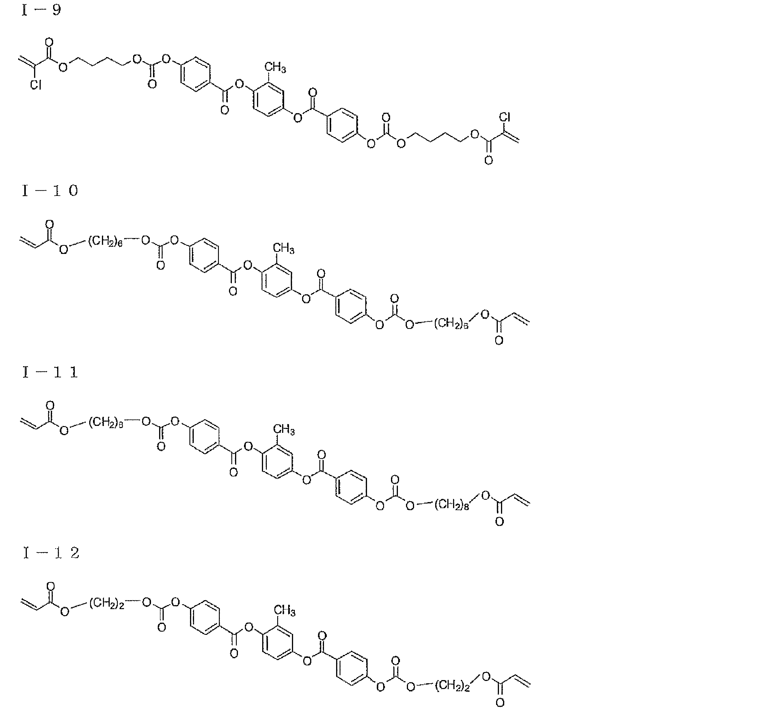
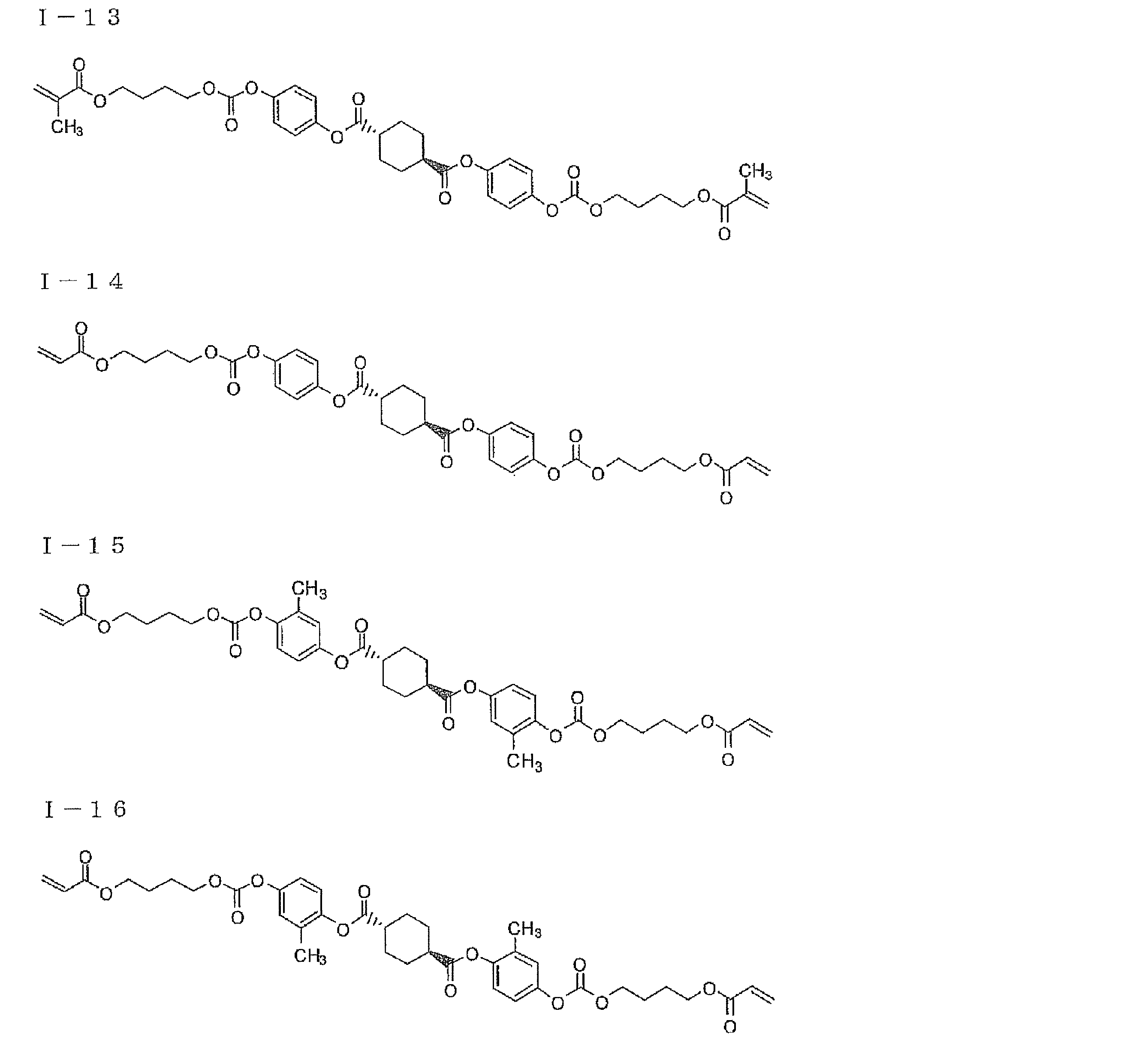

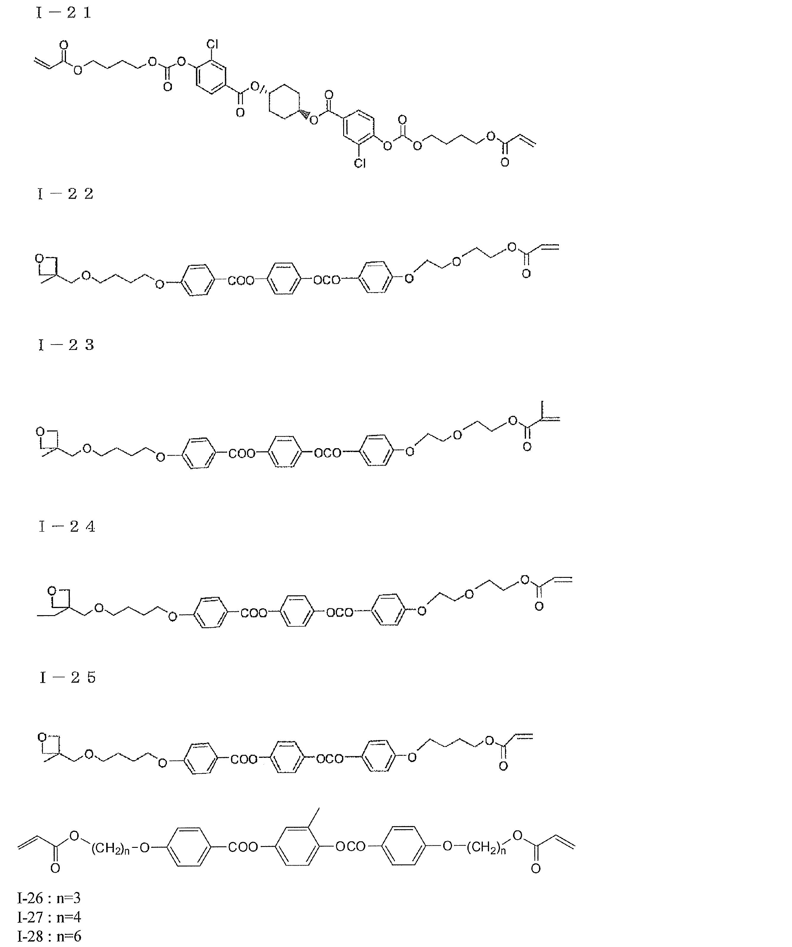
通常、棒状液晶は波長が長くなるほどレターデーションが小さくなるので、波長G(550nm)におけるレターデーションがλ/4の137.5nmのものを使用する場合、波長R(600nm)に対してはそれより小さく、逆に波長B(450nm)に対してはそれよりも大きくなってしまう。この問題を解決するためには、△nd(450nm)<△nd(550nm)<△nd(650nm)を満足する、即ち、可視光域において、位相差が波長に対して逆分散特性(波長が長いほど位相差が大きくなる性質)の棒状液晶を、第1の態様及び第2の態様に利用するそれぞれの位相差層として用いることも好ましい。このような棒状液晶の例には、特開2007-279688号公報記載の一般式(I)、一般式(II)の化合物が含まれる。
本発明の他の態様として、前記位相差層にディスコティック液晶を使用した態様がある。前記位相差層は、モノマー等の低分子量の液晶性ディスコティック化合物の層または重合性の液晶性ディスコティック化合物の重合(硬化)により得られるポリマーの層であるのが好ましい。前記ディスコティック(円盤状)化合物の例としては、C.Destradeらの研究報告、Mol.Cryst.71巻、111頁(1981年)に記載されているベンゼン誘導体、C.Destradeらの研究報告、Mol.Cryst.122巻、141頁(1985年)、Physicslett,A,78巻、82頁(1990)に記載されているトルキセン誘導体、B.Kohneらの研究報告、Angew.Chem.96巻、70頁(1984年)に記載されたシクロヘキサン誘導体およびJ.M.Lehnらの研究報告、J.Chem.Commun.,1794頁(1985年)、J.Zhangらの研究報告、J.Am.Chem.Soc.116巻、2655頁(1994年)に記載されているアザクラウン系やフェニルアセチレン系マクロサイクルなどを挙げることができる。上記ディスコティック(円盤状)化合物は、一般的にこれらを分子中心の円盤状の母核とし、直鎖のアルキル基やアルコキシ基、置換ベンゾイルオキシ基等の基(L)が放射線状に置換された構造であり、液晶性を示し、一般的にディスコティック液晶とよばれるものが含まれる。ただし、このような分子の集合体が一様に配向した場合は負の一軸性を示すが、この記載に限定されるものではない。また、本発明において、円盤状化合物から形成したとは、最終的にできた物が前記化合物である必要はなく、例えば、前記低分子ディスコティック液晶が熱、光等で反応する基を有しており、結果的に熱、光等で反応により重合または架橋し、高分子量化し液晶性を失ったものも含まれる。
本発明では、下記一般式(III)で表わされるディスコティック液晶性化合物を用いるのが好ましい。
一般式(III): D(-L-P)n
式中、Dは円盤状コアであり、Lは二価の連結基であり、Pは重合性基であり、nは4~12の整数である。
前記式(III)中、円盤状コア(D)、二価の連結基(L)および重合性基(P)の好ましい具体例は、それぞれ、特開2001-4837号公報に記載の(D1)~(D15)、(L1)~(L25)、(P1)~(P18)が挙げられ、同公報に記載される円盤状コア(D)、二価の連結基(L)および重合性基(P)に関する内容をここに好ましく適用することができる。
上記ディスコティック化合物の好ましい例を下記に示す。
一般式(III): D(-L-P)n
式中、Dは円盤状コアであり、Lは二価の連結基であり、Pは重合性基であり、nは4~12の整数である。
前記式(III)中、円盤状コア(D)、二価の連結基(L)および重合性基(P)の好ましい具体例は、それぞれ、特開2001-4837号公報に記載の(D1)~(D15)、(L1)~(L25)、(P1)~(P18)が挙げられ、同公報に記載される円盤状コア(D)、二価の連結基(L)および重合性基(P)に関する内容をここに好ましく適用することができる。
上記ディスコティック化合物の好ましい例を下記に示す。
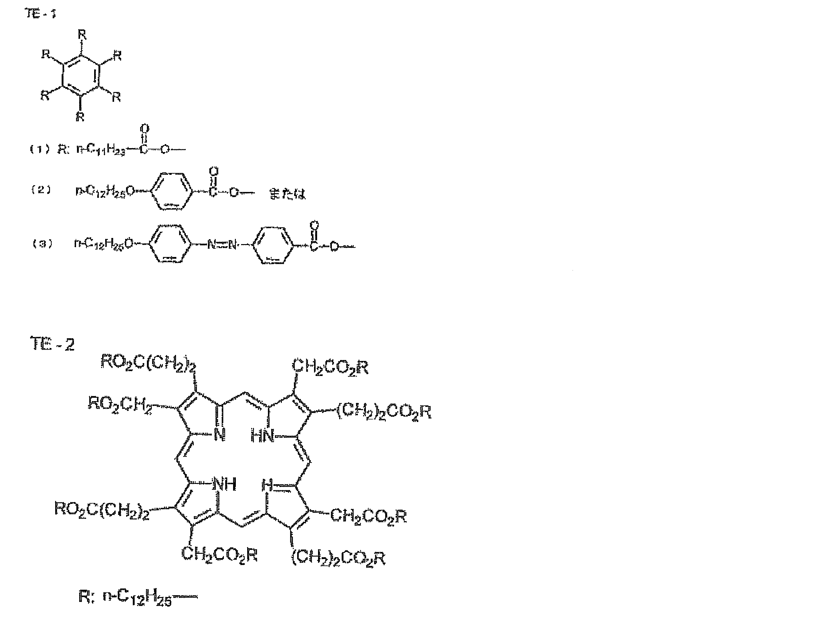

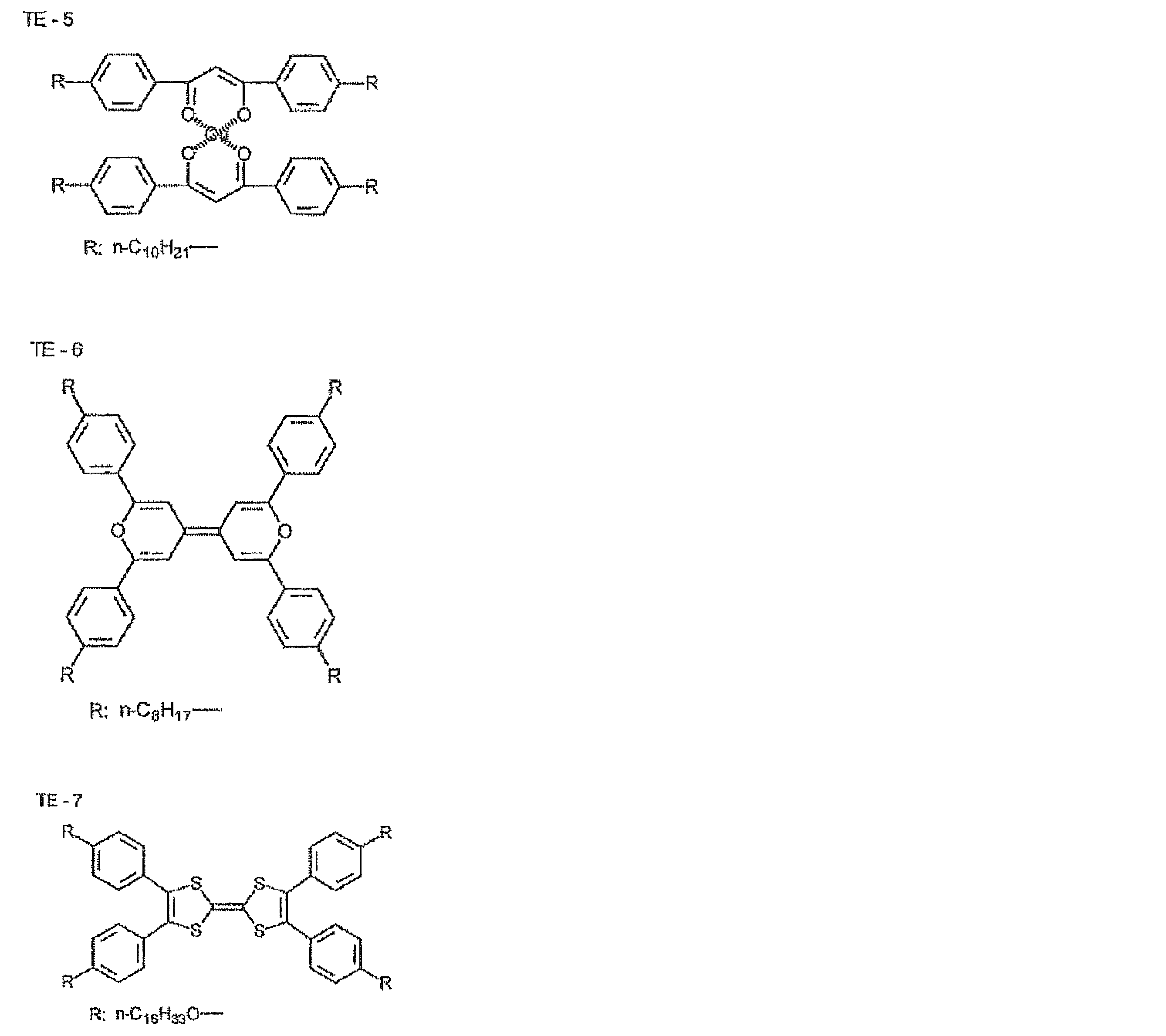
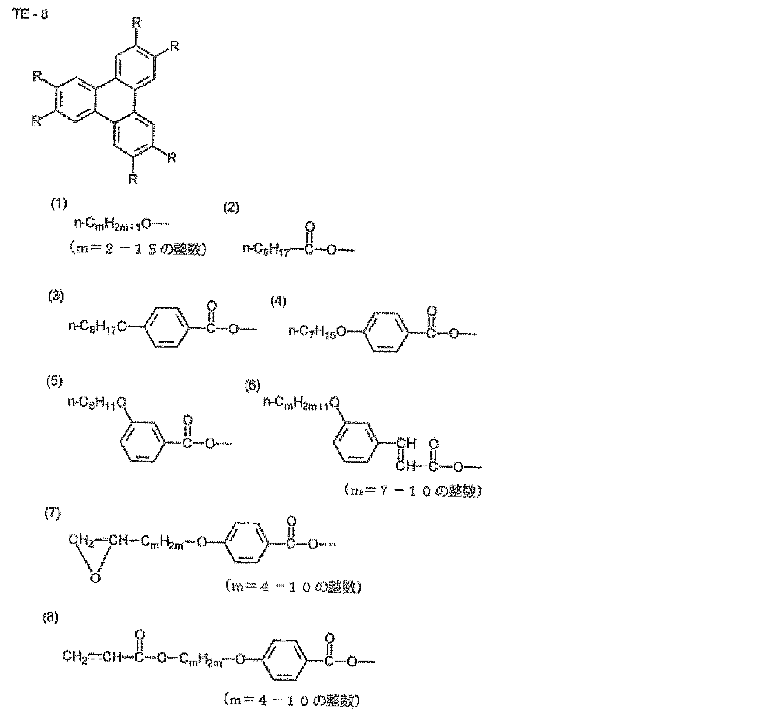

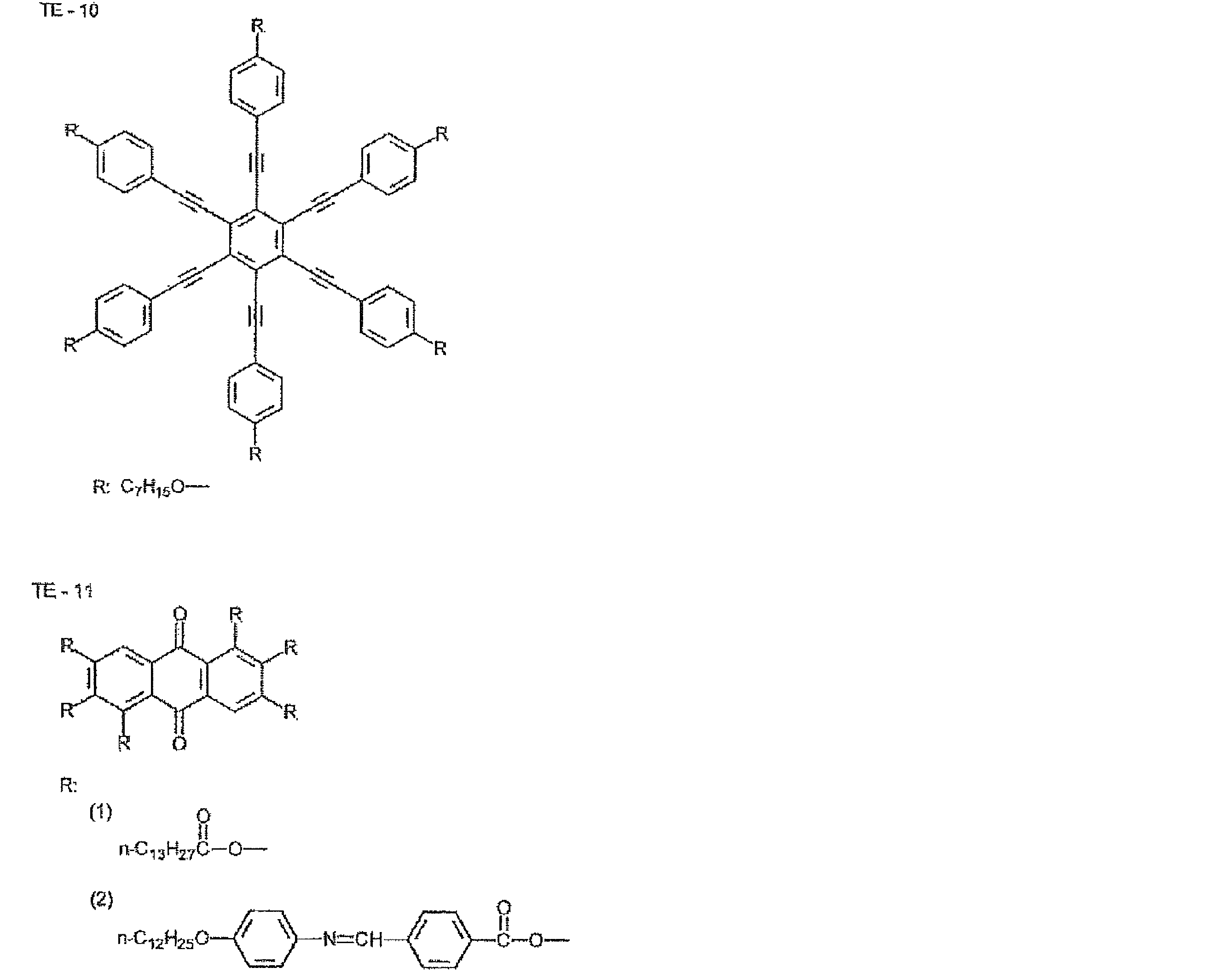
前記位相差層の主原料として使用可能なディスコティック液晶としては、下記一般式(II)又は(III)で表されるディスコティック液晶であることが特に好ましい。

式中、L、H、Qは、前記一般式(I)におけるL、H、Qとそれぞれ同義であり、好ましい範囲も同様である。

式中、Y1、Y2、及びY3は、後述する一般式(IV)におけるY11、Y12、及びY13と同義であり、その好ましい範囲も同一である。また、L1、L2、L3、H1、H2、H3、R1、R2、及びR3も、後述する一般式(IV)におけるL1、L2、L3、H1、H2、H3、R1、R2、R3と同義であり、その好ましい範囲も同一である。
分子内に複数個の芳香環を有しているディスコティック液晶は、配向制御剤として用いられるピリジニウム化合物又はイミダゾリウム化合物等のオニウム塩との間に分子間π-π相互作用が起こるため、垂直配向を実現できる。特に、例えば、一般式(II)において、Lが、*-CH=CH-又は*-C≡C-のいずれか一方を少なくとも一つ以上含む二価の連結基である場合、及び、一般式(III)において、複数個の芳香環及び複素環が単結合で連結される場合は、該連結基により結合の自由回転が強く束縛されることにより分子の直線性が保持されるため、液晶性が向上すると共に、より強い分子間π-π相互作用が起こり安定な垂直配向が実現できる。
前記ディスコティック液晶としては、下記一般式(IV)で表される化合物が好ましい。
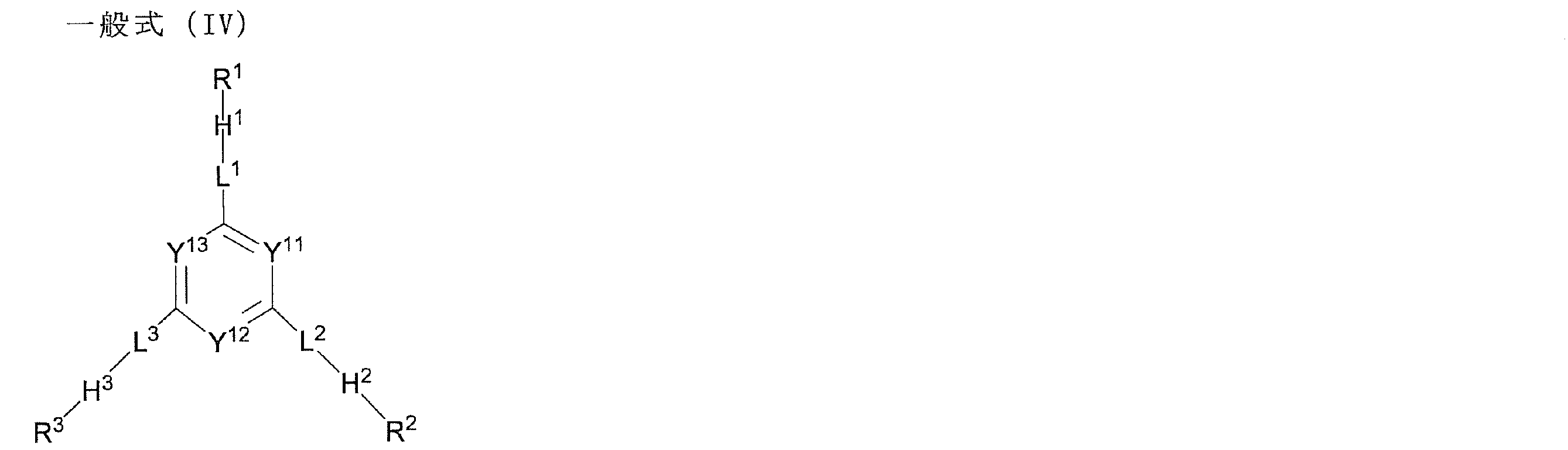
式中、Y11、Y12及びY13は、それぞれ独立に置換されていてもよいメチン又は窒素原子を表す。
Y11、Y12およびY13がメチンの場合、メチンの水素原子は置換基で置き換わってもよい。メチンが有していてもよい置換基としては、アルキル基、アルコキシ基、アリールオキシ基、アシル基、アルコキシカルボニル基、アシルオキシ基、アシルアミノ基、アルコキシカルボニルアミノ基、アルキルチオ基、アリールチオ基、ハロゲン原子およびシアノ基を好ましい例として挙げることができる。これらの置換基の中では、アルキル基、アルコキシ基、アルコキシカルボニル基、アシルオキシ基、ハロゲン原子およびシアノ基がさらに好ましく、炭素数1~12のアルキル基、炭素数1~12のアルコキシ基、炭素数2~12アルコキシカルボニル基、炭素数2~12アシルオキシ基、ハロゲン原子およびシアノ基がより好ましい。
Y11、Y12およびY13は、化合物の合成の容易さおよびコストの点において、いずれもメチンであることがより好ましく、メチンは無置換であることがさらに好ましい。
Y11、Y12およびY13は、化合物の合成の容易さおよびコストの点において、いずれもメチンであることがより好ましく、メチンは無置換であることがさらに好ましい。
L1、L2及びL3は、それぞれ独立に単結合又は二価の連結基を表す。
L1、L2およびL3が二価の連結基の場合、それぞれ独立に、-O-,-S-、-C(=O)-、-NR7-、-CH=CH-、-C≡C-、二価の環状基およびこれらの組み合わせからなる群より選ばれる二価の連結基であることが好ましい。上記R7は炭素原子数1~7のアルキル基または水素原子であり、炭素原子数1~4のアルキル基または水素原子であることが好ましく、メチル基、エチル基または水素原子であることがさらに好ましく、水素原子であることが最も好ましい。
L1、L2およびL3が二価の連結基の場合、それぞれ独立に、-O-,-S-、-C(=O)-、-NR7-、-CH=CH-、-C≡C-、二価の環状基およびこれらの組み合わせからなる群より選ばれる二価の連結基であることが好ましい。上記R7は炭素原子数1~7のアルキル基または水素原子であり、炭素原子数1~4のアルキル基または水素原子であることが好ましく、メチル基、エチル基または水素原子であることがさらに好ましく、水素原子であることが最も好ましい。
L1、L2およびL3における二価の環状基とは、少なくとも1種類の環状構造を有する二価の連結基(以下、環状基と呼ぶことがある)である。環状基は5員環、6員環、または7員環であることが好ましく、5員環または6員環であることがさらに好ましく、6員環であることが最も好ましい。環状基に含まれる環は、縮合環であってもよい。ただし、縮合環よりも単環であることがより好ましい。また、環状基に含まれる環は、芳香族環、脂肪族環、および複素環のいずれでもよい。芳香族環としては、ベンゼン環およびナフタレン環が好ましい例として挙げられる。脂肪族環としては、シクロヘキサン環が好ましい例として挙げられる。複素環としては、ピリジン環およびピリミジン環が好ましい例として挙げられる。環状基は、芳香族環および複素環がより好ましい。なお、本発明における2価の環状基は、環状構造のみ(但し、置換基を含む)からなる2価の連結基であることがより好ましい(以下、同じ)。
L1、L2およびL3で表される二価の環状基のうち、ベンゼン環を有する環状基としては、1,4-フェニレン基が好ましい。ナフタレン環を有する環状基としては、ナフタレン-1,5-ジイル基およびナフタレン-2,6-ジイル基が好ましい。シクロヘキサン環を有する環状基としては1,4-シクロへキシレン基であることが好ましい。ピリジン環を有する環状基としてはピリジン-2,5-ジイル基が好ましい。ピリミジン環を有する環状基としては、ピリミジン-2,5-ジイル基が好ましい。
L1、L2およびL3で表される二価の環状基は、置換基を有していてもよい。置換基としては、ハロゲン原子(好ましくは、フッ素原子、塩素原子)、シアノ基、ニトロ基、炭素原子数1~16のアルキル基、炭素原子数2~16のアルケニル基、炭素原子数が2~16アルキニル基、炭素原子数1~16のハロゲン置換アルキル基、炭素原子数1~16のアルコキシ基、炭素原子数2~16のアシル基、炭素原子数1~16のアルキルチオ基、炭素原子数2~16のアシルオキシ基、炭素原子数2~16のアルコキシカルボニル基、カルバモイル基、炭素原子数2~16のアルキル基で置換されたカルバモイル基および炭素原子数2~16のアシルアミノ基が含まれる。
L1、L2およびL3としては、単結合、*-O-CO-、*-CO-O-、*-CH=CH-、*-C≡C-、*-二価の環状基-、*-O-CO-二価の環状基-、*-CO-O-二価の環状基-、*-CH=CH-二価の環状基-、*-C≡C-二価の環状基-、*-二価の環状基-O-CO-、*-二価の環状基-CO-O-、*-二価の環状基-CH=CH-および*-二価の環状基-C≡C-が好ましい。特に、単結合、*-CH=CH-、*-C≡C-、*-CH=CH-二価の環状基-および*-C≡C-二価の環状基-が好ましく、単結合が最も好ましい。ここで、*は一般式(IV)中のY11、Y12およびY13を含む6員環側に結合する位置を表す。
一般式(I)中、H1、H2及びH3は、それぞれ独立に一般式(IV-A)又は(IV-B)の基を表す。

XAは、酸素原子、硫黄原子、メチレン又はイミノを表し;
*は上記一般式(IV)におけるL1~L3側と結合する位置を表し;
**は上記一般式(IV)におけるR1~R3側と結合する位置を表す。

XBは、酸素原子、硫黄原子、メチレン又はイミノを表し;
*は上記一般式(IV)におけるL1~L3側と結合する位置を表し;
**は上記一般式(IV)におけるR1~R3側と結合する位置を表す。
一般式(IV)中、R1、R2及びR3は、それぞれ独立に下記一般式(IV-R)を表す。
一般式(IV-R)
*-(-L21-Q2)n1-L22-L23-Q1
一般式(IV-R)中、*は、一般式(IV)におけるH1~H3側と結合する位置を表す。
L21は単結合又は二価の連結基を表す。L21が二価の連結基の場合、-O-、-S-、-C(=O)-、-NR7-、-CH=CH-および-C≡C-ならびにこれらの組み合わせからなる群より選ばれる二価の連結基であることが好ましい。上記R7は炭素原子数1~7のアルキル基または水素原子であり、炭素原子数1~4のアルキル基または水素原子であることが好ましく、メチル基、エチル基または水素原子であることがさらに好ましく、水素原子であることが最も好ましい。
*-(-L21-Q2)n1-L22-L23-Q1
一般式(IV-R)中、*は、一般式(IV)におけるH1~H3側と結合する位置を表す。
L21は単結合又は二価の連結基を表す。L21が二価の連結基の場合、-O-、-S-、-C(=O)-、-NR7-、-CH=CH-および-C≡C-ならびにこれらの組み合わせからなる群より選ばれる二価の連結基であることが好ましい。上記R7は炭素原子数1~7のアルキル基または水素原子であり、炭素原子数1~4のアルキル基または水素原子であることが好ましく、メチル基、エチル基または水素原子であることがさらに好ましく、水素原子であることが最も好ましい。
L21は単結合、***-O-CO-、***-CO-O-、***-CH=CH-および***-C≡C-(ここで、***は一般式(DI-R)中の*側を表す)のいずれかが好ましく、単結合がより好ましい。
Q2は少なくとも1種類の環状構造を有する二価の基(環状基)を表す。このような環状基としては、5員環、6員環、または7員環を有する環状基が好ましく、5員環または6員環を有する環状基がより好ましく、6員環を有する環状基がさらに好ましい。上記環状基に含まれる環状構造は、縮合環であっても良い。ただし、縮合環よりも単環であることがより好ましい。また、環状基に含まれる環は、芳香族環、脂肪族環、および複素環のいずれでもよい。芳香族環としては、ベンゼン環、ナフタレン環、アントラセン環、フェナントレン環が好ましい例として挙げられる。脂肪族環としては、シクロヘキサン環が好ましい例として挙げられる。複素環としては、ピリジン環およびピリミジン環が好ましい例として挙げられる。
上記Q2のうち、ベンゼン環を有する環状基としては、1,4-フェニレン基が好ましい。ナフタレン環を有する環状基としては、ナフタレン-1,4-ジイル基、ナフタレン-1,5-ジイル基、ナフタレン-1,6-ジイル基、ナフタレン-2,5-ジイル基、ナフタレン-2,6-ジイルナフタレン-2,7-ジイル基が好ましい。シクロヘキサン環を有する環状基としては1,4-シクロへキシレン基であることが好ましい。ピリジン環を有する環状基としてはピリジン-2,5-ジイル基が好ましい。ピリミジン環を有する環状基としては、ピリミジン-2,5-ジイル基が好ましい。これらの中でも、特に、1,4-フェニレン基、ナフタレン-2,6-ジイル基および1,4-シクロへキシレン基が好ましい。
Q2は、置換基を有していてもよい。置換基の例には、ハロゲン原子(フッ素原子、塩素原子、臭素原子、ヨウ素原子)、シアノ基、ニトロ基、炭素原子数1~16のアルキル基、炭素原子数2~16のアルケニル基、炭素原子数2~16のアルキニル基、炭素原子数1~16のハロゲンで置換されたアルキル基、炭素原子数1~16のアルコキシ基、炭素原子数2~16のアシル基、炭素原子数1~16のアルキルチオ基、炭素原子数2~16のアシルオキシ基、炭素原子数2~16のアルコキシカルボニル基、カルバモイル基、炭素原子数2~16のアルキル置換カルバモイル基および炭素原子数2~16のアシルアミノ基が含まれる。これらの中でも、ハロゲン原子、シアノ基、炭素原子数1~6のアルキル基、炭素原子数1~6のハロゲンで置換されたアルキル基が好ましく、ハロゲン原子、炭素原子数1~4のアルキル基、炭素原子数1~4のハロゲンで置換されたアルキル基がより好ましく、ハロゲン原子、炭素原子数が1~3のアルキル基、トリフルオロメチル基がさらに好ましい。
n1は、0~4の整数を表す。n1としては、1~3の整数が好ましく、1もしくは2がさらに好ましい。
L22は、**-O-、**-O-CO-、**-CO-O-、**-O-CO-O-、**-S-、**-NH-、**-SO2-、**-CH2-、**-CH=CH-または**-C≡C-を表し、**はQ2側と結合する位置を表す。
L22は、好ましくは、**-O-、**-O-CO-、**-CO-O-、**-O-CO-O-、**-CH2-、**-CH=CH-、**-C≡C-であり、より好ましくは、**-O-、**-O-CO-、**-O-CO-O-、**-CH2-である。L22が水素原子を含む基であるときは、該水素原子は置換基で置換されていてもよい。このような置換基として、ハロゲン原子、シアノ基、ニトロ基、炭素原子数1~6のアルキル基、炭素原子数1~6のハロゲンで置換されたアルキル基、炭素原子数1~6のアルコキシ基、炭素原子数2~6のアシル基、炭素原子数1~6のアルキルチオ基、炭素原子数2~6のアシルオキシ基、炭素原子数2~6のアルコキシカルボニル基、カルバモイル基、炭素原子数2~6のアルキルで置換されたカルバモイル基および炭素原子数2~6のアシルアミノ基が好ましい例として挙げられ、ハロゲン原子、炭素原子数1~6のアルキル基がより好ましい。
L22は、好ましくは、**-O-、**-O-CO-、**-CO-O-、**-O-CO-O-、**-CH2-、**-CH=CH-、**-C≡C-であり、より好ましくは、**-O-、**-O-CO-、**-O-CO-O-、**-CH2-である。L22が水素原子を含む基であるときは、該水素原子は置換基で置換されていてもよい。このような置換基として、ハロゲン原子、シアノ基、ニトロ基、炭素原子数1~6のアルキル基、炭素原子数1~6のハロゲンで置換されたアルキル基、炭素原子数1~6のアルコキシ基、炭素原子数2~6のアシル基、炭素原子数1~6のアルキルチオ基、炭素原子数2~6のアシルオキシ基、炭素原子数2~6のアルコキシカルボニル基、カルバモイル基、炭素原子数2~6のアルキルで置換されたカルバモイル基および炭素原子数2~6のアシルアミノ基が好ましい例として挙げられ、ハロゲン原子、炭素原子数1~6のアルキル基がより好ましい。
L23は、-O-、-S-、-C(=O)-、-SO2-、-NH-、-CH2-、-CH=CH-および-C≡C-ならびにこれらの組み合わせからなる群より選ばれる二価の連結基を表す。ここで、-NH-、-CH2-、-CH=CH-の水素原子は、置換基で置換されていてもよい。このような置換基として、ハロゲン原子、シアノ基、ニトロ基、炭素原子数1~6のアルキル基、炭素原子数1~6のハロゲンで置換されたアルキル基、炭素原子数1~6のアルコキシ基、炭素原子数2~6のアシル基、炭素原子数1~6のアルキルチオ基、炭素原子数2~6のアシルオキシ基、炭素原子数2~6のアルコキシカルボニル基、カルバモイル基、炭素原子数2~6のアルキルで置換されたカルバモイル基および炭素原子数2~6のアシルアミノ基が好ましい例として挙げられ、ハロゲン原子、炭素原子数1~6のアルキル基がより好ましい。これらの置換基に置換されることにより、本発明の液晶性化合物から液晶性組成物を調製する際に、使用する溶媒に対する溶解性を向上させることができる。
L23は、-O-、-C(=O)-、-CH2-、-CH=CH-および-C≡C-ならびにこれらの組み合わせからなる群より選ばれることが好ましい。L23は、炭素原子を1~20個含有することが好ましく、炭素原子を2~14個を含有することがより好ましい。さらに、L23は、-CH2-を1~16個含有することが好ましく、-CH2-を2~12個含有することがさらに好ましい。
Q1は重合性基または水素原子を表す。本発明の液晶性化合物を光学補償フィルムのような位相差の大きさが熱により変化しないものが好ましい光学フィルム等に用いる場合には、Q1は重合性基であることが好ましい。重合反応は、付加重合(開環重合を含む)または縮合重合であることが好ましい。すなわち、重合性基は、付加重合反応または縮合重合反応が可能な官能基であることが好ましい。以下に重合性基の例を示す。
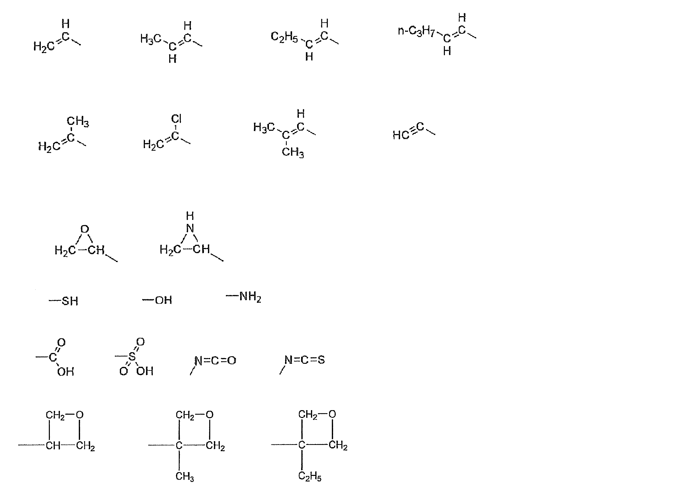
さらに、重合性基は付加重合反応が可能な官能基であることが特に好ましい。そのような重合性基としては、重合性エチレン性不飽和基または開環重合性基が好ましい。
重合性エチレン性不飽和基の例としては、下記の式(M-1)~(M-6)が挙げられる。
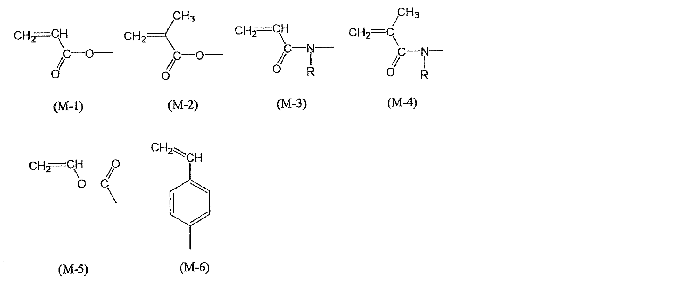
式(M-3)、(M-4)中、Rは水素原子またはアルキル基を表し、水素原子またはメチル基が好ましい。
上記式(M-1)~(M-6)の中、(M-1)または(M-2)が好ましく、(M-1)がより好ましい。
上記式(M-1)~(M-6)の中、(M-1)または(M-2)が好ましく、(M-1)がより好ましい。
開環重合性基は、環状エーテル基が好ましく、エポキシ基またはオキセタニル基がより好ましい。
前記式(IV)の化合物の中でも、下記一般式(IV’)で表される化合物がより好ましい。

一般式(DIV)中、Y11、Y12およびY13は、それぞれ独立にメチンまたは窒素原子を表し、メチンが好ましく、メチンは無置換であるのが好ましい。
R11、R12およびR13は、それぞれ独立に下記一般式(IV’-A)、下記一般式(IV’-B)または下記一般式(IV’-C)を表す。固有複屈折の波長分散性を小さくしようとする場合、一般式(IV’-A)または一般式(IV’-C)が好ましく、一般式(IV’-A)がより好ましい。R11、R12およびR13は、R11=R12=R13であることが好ましい。

一般式(IV’-A)中、A11、A12、A13、A14、A15およびA16は、それぞれ独立にメチンまたは窒素原子を表す。
A11およびA12は、少なくとも一方が窒素原子であることが好ましく、両方が窒素原子であることがより好ましい。
A13、A14、A15およびA16は、それらのうち、少なくとも3つがメチンであることが好ましく、すべてメチンであることがより好ましい。さらに、メチンは無置換であることが好ましい。
A11、A12、A13、A14、A15またはA16がメチンの場合の置換基の例には、ハロゲン原子(フッ素原子、塩素原子、臭素原子、ヨウ素原子)、シアノ基、ニトロ基、炭素原子数1~16のアルキル基、炭素原子数2~16のアルケニル基、炭素原子数2~16のアルキニル基、炭素原子数1~16のハロゲンで置換されたアルキル基、炭素原子数1~16のアルコキシ基、炭素原子数2~16のアシル基、炭素原子数1~16のアルキルチオ基、炭素原子数2~16のアシルオキシ基、炭素原子数2~16のアルコキシカルボニル基、カルバモイル基、炭素原子数2~16のアルキル置換カルバモイル基および炭素原子数2~16のアシルアミノ基が含まれる。これらの中でも、ハロゲン原子、シアノ基、炭素原子数1~6のアルキル基、炭素原子数1~6のハロゲンで置換されたアルキル基が好ましく、ハロゲン原子、炭素原子数1~4のアルキル基、炭素原子数1~4のハロゲンで置換されたアルキル基がより好ましく、ハロゲン原子、炭素原子数が1~3のアルキル基、トリフルオロメチル基がさらに好ましい。
X1は、酸素原子、硫黄原子、メチレンまたはイミノを表し、酸素原子が好ましい。
A11およびA12は、少なくとも一方が窒素原子であることが好ましく、両方が窒素原子であることがより好ましい。
A13、A14、A15およびA16は、それらのうち、少なくとも3つがメチンであることが好ましく、すべてメチンであることがより好ましい。さらに、メチンは無置換であることが好ましい。
A11、A12、A13、A14、A15またはA16がメチンの場合の置換基の例には、ハロゲン原子(フッ素原子、塩素原子、臭素原子、ヨウ素原子)、シアノ基、ニトロ基、炭素原子数1~16のアルキル基、炭素原子数2~16のアルケニル基、炭素原子数2~16のアルキニル基、炭素原子数1~16のハロゲンで置換されたアルキル基、炭素原子数1~16のアルコキシ基、炭素原子数2~16のアシル基、炭素原子数1~16のアルキルチオ基、炭素原子数2~16のアシルオキシ基、炭素原子数2~16のアルコキシカルボニル基、カルバモイル基、炭素原子数2~16のアルキル置換カルバモイル基および炭素原子数2~16のアシルアミノ基が含まれる。これらの中でも、ハロゲン原子、シアノ基、炭素原子数1~6のアルキル基、炭素原子数1~6のハロゲンで置換されたアルキル基が好ましく、ハロゲン原子、炭素原子数1~4のアルキル基、炭素原子数1~4のハロゲンで置換されたアルキル基がより好ましく、ハロゲン原子、炭素原子数が1~3のアルキル基、トリフルオロメチル基がさらに好ましい。
X1は、酸素原子、硫黄原子、メチレンまたはイミノを表し、酸素原子が好ましい。

一般式(IV’-B)中、A21、A22、A23、A24、A25およびA26は、それぞれ独立にメチンまたは窒素原子を表す。
A21およびA22は、少なくとも一方が窒素原子であることが好ましく、両方が窒素原子であることがより好ましい。
A23、A24、A25およびA26は、それらのうち、少なくとも3つがメチンであることが好ましく、すべてメチンであることがより好ましい。
A21、A22、A23、A24、A25またはA26がメチンの場合の置換基の例には、ハロゲン原子(フッ素原子、塩素原子、臭素原子、ヨウ素原子)、シアノ基、ニトロ基、炭素原子数1~16のアルキル基、炭素原子数2~16のアルケニル基、炭素原子数2~16のアルキニル基、炭素原子数1~16のハロゲンで置換されたアルキル基、炭素原子数1~16のアルコキシ基、炭素原子数2~16のアシル基、炭素原子数1~16のアルキルチオ基、炭素原子数2~16のアシルオキシ基、炭素原子数2~16のアルコキシカルボニル基、カルバモイル基、炭素原子数2~16のアルキル置換カルバモイル基および炭素原子数2~16のアシルアミノ基が含まれる。これらの中でも、ハロゲン原子、シアノ基、炭素原子数1~6のアルキル基、炭素原子数1~6のハロゲンで置換されたアルキル基が好ましく、ハロゲン原子、炭素原子数1~4のアルキル基、炭素原子数1~4のハロゲンで置換されたアルキル基がより好ましく、ハロゲン原子、炭素原子数が1~3のアルキル基、トリフルオロメチル基がさらに好ましい。
X2は、酸素原子、硫黄原子、メチレンまたはイミノを表し、酸素原子が好ましい。
A21およびA22は、少なくとも一方が窒素原子であることが好ましく、両方が窒素原子であることがより好ましい。
A23、A24、A25およびA26は、それらのうち、少なくとも3つがメチンであることが好ましく、すべてメチンであることがより好ましい。
A21、A22、A23、A24、A25またはA26がメチンの場合の置換基の例には、ハロゲン原子(フッ素原子、塩素原子、臭素原子、ヨウ素原子)、シアノ基、ニトロ基、炭素原子数1~16のアルキル基、炭素原子数2~16のアルケニル基、炭素原子数2~16のアルキニル基、炭素原子数1~16のハロゲンで置換されたアルキル基、炭素原子数1~16のアルコキシ基、炭素原子数2~16のアシル基、炭素原子数1~16のアルキルチオ基、炭素原子数2~16のアシルオキシ基、炭素原子数2~16のアルコキシカルボニル基、カルバモイル基、炭素原子数2~16のアルキル置換カルバモイル基および炭素原子数2~16のアシルアミノ基が含まれる。これらの中でも、ハロゲン原子、シアノ基、炭素原子数1~6のアルキル基、炭素原子数1~6のハロゲンで置換されたアルキル基が好ましく、ハロゲン原子、炭素原子数1~4のアルキル基、炭素原子数1~4のハロゲンで置換されたアルキル基がより好ましく、ハロゲン原子、炭素原子数が1~3のアルキル基、トリフルオロメチル基がさらに好ましい。
X2は、酸素原子、硫黄原子、メチレンまたはイミノを表し、酸素原子が好ましい。
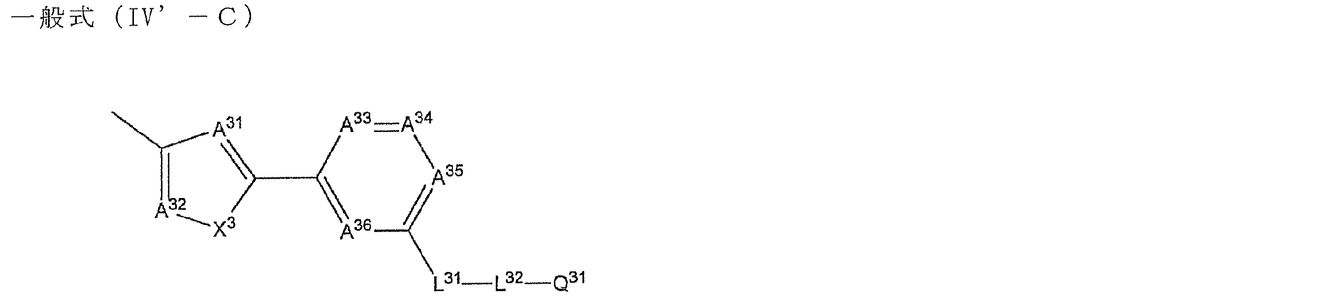
一般式(IV’-C)中、A31、A32、A33、A34、A35およびA36は、それぞれ独立にメチンまたは窒素原子を表す。
A31およびA32は、少なくとも一方が窒素原子であることが好ましく、両方が窒素原子であることがより好ましい。
A33、A34、A35およびA36は、少なくとも3つがメチンであることが好ましく、すべてメチンであることがより好ましい。
A31、A32、A33、A34、A35またはA36がメチンの場合、メチンは置換基を有していてもよい。置換基の例には、ハロゲン原子(フッ素原子、塩素原子、臭素原子、ヨウ素原子)、シアノ基、ニトロ基、炭素原子数1~16のアルキル基、炭素原子数2~16のアルケニル基、炭素原子数2~16のアルキニル基、炭素原子数1~16のハロゲンで置換されたアルキル基、炭素原子数1~16のアルコキシ基、炭素原子数2~16のアシル基、炭素原子数1~16のアルキルチオ基、炭素原子数2~16のアシルオキシ基、炭素原子数2~16のアルコキシカルボニル基、カルバモイル基、炭素原子数2~16のアルキル置換カルバモイル基および炭素原子数2~16のアシルアミノ基が含まれる。これらの中でも、ハロゲン原子、シアノ基、炭素原子数1~6のアルキル基、炭素原子数1~6のハロゲンで置換されたアルキル基が好ましく、ハロゲン原子、炭素原子数1~4のアルキル基、炭素原子数1~4のハロゲンで置換されたアルキル基がより好ましく、ハロゲン原子、炭素原子数が1~3のアルキル基、トリフルオロメチル基がさらに好ましい。
X3は、酸素原子、硫黄原子、メチレンまたはイミノを表し、酸素原子が好ましい。
A31およびA32は、少なくとも一方が窒素原子であることが好ましく、両方が窒素原子であることがより好ましい。
A33、A34、A35およびA36は、少なくとも3つがメチンであることが好ましく、すべてメチンであることがより好ましい。
A31、A32、A33、A34、A35またはA36がメチンの場合、メチンは置換基を有していてもよい。置換基の例には、ハロゲン原子(フッ素原子、塩素原子、臭素原子、ヨウ素原子)、シアノ基、ニトロ基、炭素原子数1~16のアルキル基、炭素原子数2~16のアルケニル基、炭素原子数2~16のアルキニル基、炭素原子数1~16のハロゲンで置換されたアルキル基、炭素原子数1~16のアルコキシ基、炭素原子数2~16のアシル基、炭素原子数1~16のアルキルチオ基、炭素原子数2~16のアシルオキシ基、炭素原子数2~16のアルコキシカルボニル基、カルバモイル基、炭素原子数2~16のアルキル置換カルバモイル基および炭素原子数2~16のアシルアミノ基が含まれる。これらの中でも、ハロゲン原子、シアノ基、炭素原子数1~6のアルキル基、炭素原子数1~6のハロゲンで置換されたアルキル基が好ましく、ハロゲン原子、炭素原子数1~4のアルキル基、炭素原子数1~4のハロゲンで置換されたアルキル基がより好ましく、ハロゲン原子、炭素原子数が1~3のアルキル基、トリフルオロメチル基がさらに好ましい。
X3は、酸素原子、硫黄原子、メチレンまたはイミノを表し、酸素原子が好ましい。
一般式(IV’-A)中のL11、一般式(IV’-B)中のL21、一般式(IV’-C)中のL31はそれぞれ独立して、-O-、-C(=O)-、-O-CO-、-CO-O-、-O-CO-O-、-S-、-NH-、-SO2-、-CH2-、-CH=CH-または-C≡C-を表す。好ましくは、-O-、-C(=O)-、-O-CO-、-CO-O-、-O-CO-O-、-CH2-、-CH=CH-、-C≡C-であり、より好ましくは、-O-、-O-CO-、-CO-O-、-O-CO-O-、-C≡C-である。特に、小さい固有複屈折の波長分散性が期待できる、一般式(DI-A)中のL11は、-O-、-CO-O-、-C≡C-が特に好ましく、この中でも-CO-O-が、より高温でディスコティックネマチック相を発現できるため、好ましい。上述の基が水素原子を含む基であるときは、該水素原子は置換基で置き換わってもよい。このような置換基として、ハロゲン原子、シアノ基、ニトロ基、炭素原子数1~6のアルキル基、炭素原子数1~6のハロゲンで置換されたアルキル基、炭素原子数1~6のアルコキシ基、炭素原子数2~6のアシル基、炭素原子数1~6のアルキルチオ基、炭素原子数2~6のアシルオキシ基、炭素原子数2~6のアルコキシカルボニル基、カルバモイル基、炭素原子数2~6のアルキルで置換されたカルバモイル基および炭素原子数2~6のアシルアミノ基が好ましい例として挙げられ、ハロゲン原子、炭素原子数1~6のアルキル基がより好ましい。
一般式(IV’-A)中のL12、一般式(IV’-B)中のL22、一般式(IV’-C)中のL32はそれぞれ独立して、-O-、-S-、-C(=O)-、-SO2-、-NH-、-CH2-、-CH=CH-および-C≡C-ならびにこれらの組み合わせからなる群より選ばれる二価の連結基を表す。ここで、-NH-、-CH2-、-CH=CH-の水素原子は、置換基で置換されていてもよい。このような置換基として、ハロゲン原子、シアノ基、ニトロ基、水酸基、カルボキシル基、炭素原子数1~6のアルキル基、炭素原子数1~6のハロゲンで置換されたアルキル基、炭素原子数1~6のアルコキシ基、炭素原子数2~6のアシル基、炭素原子数1~6のアルキルチオ基、炭素原子数2~6のアシルオキシ基、炭素原子数2~6のアルコキシカルボニル基、カルバモイル基、炭素原子数2~6のアルキルで置換されたカルバモイル基および炭素原子数2~6のアシルアミノ基が好ましい例として挙げられ、ハロゲン原子、水酸基、炭素原子数1~6のアルキル基がより好ましく、特にハロゲン原子、メチル基、エチル基が好ましい。
L12、L22、L32はそれぞれ独立して、-O-、-C(=O)-、-CH2-、-CH=CH-および-C≡C-ならびにこれらの組み合わせからなる群より選ばれることが好ましい。
L12、L22、L32はそれぞれ独立して、炭素数1~20であることが好ましく、炭素数2~14であることがより好ましい。炭素数2~14が好ましく、-CH2-を1~16個有することがより好ましく、-CH2-を2~12個有することがさらに好ましい。
L12、L22、L32を構成する炭素数は、液晶の相転移温度と化合物の溶媒への溶解性に影響を及ぼす。一般的に炭素数は多くなるほど、ディスコティックネマチック相(ND相)から等方性液体への転移温度が低下する傾向にある。また、溶媒への溶解性は、一般的に炭素数は多くなるほど向上する傾向にある。
一般式(IV’-A)中のQ11、一般式(IV’-B)中のQ21、一般式(IV’-C)中のQ31はそれぞれ独立して重合性基または水素原子を表す。また、Q11、Q21、Q31は重合性基であることが好ましい。重合反応は、付加重合(開環重合を含む)または縮合重合であることが好ましい。すなわち、重合性基は、付加重合反応または縮合重合反応が可能な官能基であることが好ましい。以下に重合性基の例については、上記と同様であり、好ましい例も上記と同様である。
前記一般式(IV)で表される化合物の具体例には、特開2006-76992号公報の[0052]の[化13]~[化43]に記載の例示化合物、並びに特開2007-2220号公報の[0040]の[化13]~[0063]の[化36]に記載の例示化合物が含まれる。但し、これらの化合物に限定されるものではない。
上記化合物は、種々の方法により合成することができ、例えば、特開2007-2220号公報の[0064]~[0070]に記載の方法により合成することができる。
前記ディスコティック液晶化合物は、液晶相として、カラムナー相およびディスコティックネマチック相(ND相)を示すことが好ましく、これらの液晶相の中では、良好なモノドメイン性を示すディスコティックネマチック相(ND相)が好ましい。
前記ディスコティック液晶化合物の中でも、液晶相を20℃~300℃の範囲で発現させるものが好ましい。より好ましくは40℃~280℃であり、さらに好ましくは60℃~250℃である。ここで20℃~300℃で液晶相を発現するとは、液晶温度範囲が20℃をまたぐ場合(例えば、10℃~22℃)や、300℃をまたぐ場合(例えば、298℃~310℃)も含む。40℃~280℃と60℃~250℃に関しても同様である。
前記位相差層は、液晶化合物を含有する組成物(例えば塗布液)を、後述する光配向層やラビング配向層の表面に塗布し、所望の液晶相を示す配向状態とした後、該配向状態を熱又は電離放射線の照射により固定することで作製された層であることが好ましい。塗布液の調製に使用する溶媒としては、有機溶媒が好ましく用いられる。有機溶媒の例には、アミド(例、N,N-ジメチルホルムアミド)、スルホキシド(例、ジメチルスルホキシド)、ヘテロ環化合物(例、ピリジン)、炭化水素(例、ベンゼン、ヘキサン)、アルキルハライド(例、クロロホルム、ジクロロメタン)、エステル(例、酢酸メチル、酢酸ブチル)、ケトン(例、アセトン、メチルエチルケトン)、エーテル(例、テトラヒドロフラン、1,2-ジメトキシエタン)が含まれる。アルキルハライドおよびケトンが好ましい。二種類以上の有機溶媒を併用してもよい。
棒状液晶化合物を利用する場合は、棒状液晶を水平配向させるのが好ましい。尚、本明細書において「水平配向」とは、棒状液晶の子長軸と層面が平行であることをいう。厳密に平行であることを要求するものではなく、本明細書では、水平面とのなす傾斜角が10度未満の配向を意味するものとする。傾斜角は0~5度が好ましく、0~3度がより好ましく、0~2度がさらに好ましく、0~1度が最も好ましい。
なお、前記組成物中には、液晶の水平配向を促進する添加剤を添加してもよく、該添加剤の例には、特開2009-223001号公報の[0055]~[0063]に記載の化合物が含まれる。
なお、前記組成物中には、液晶の水平配向を促進する添加剤を添加してもよく、該添加剤の例には、特開2009-223001号公報の[0055]~[0063]に記載の化合物が含まれる。
一方、円盤状液晶化合物を利用する場合は、分子の円盤面を層面に対して垂直にして配向させるのが好ましい。前記一般式(IV)で表されるディスコティック液晶は、分子内に複数個の芳香環を有しているため、ピリジニウム化合物又はイミダゾリウム化合物との間に強い分子間π-π相互作用が起こり、ディスコティック液晶の配向膜界面近傍におけるチルト角を増加させる。特に、一般式(IV’)で表されるディスコティック液晶は、複数個の芳香環が単結合で連結されているため、分子の回転自由度が束縛された直線性の高い分子構造を有しているため、ピリジニウム化合物又はイミダゾリウム化合物との間により強い分子間π-π相互作用が起こり、ディスコティック液晶の配向膜界面近傍におけるチルト角を増加させ垂直配向状態が実現できる。
次に、配向させた液晶化合物は、配向状態を維持して固定することが好ましい。固定化は、液晶化合物に導入した反応性基の重合反応により実施することが好ましい。重合反応には、熱重合開始剤を用いる熱重合反応と光重合開始剤を用いる光重合反応とが含まれるが、光重合反応がより好ましい。光重合反応としては、ラジカル重合、カチオン重合のいずれでも構わない。ラジカル光重合開始剤の例には、α-カルボニル化合物(米国特許2367661号、同2367670号の各明細書記載)、アシロインエーテル(米国特許2448828号明細書記載)、α-炭化水素置換芳香族アシロイン化合物(米国特許2722512号明細書記載)、多核キノン化合物(米国特許3046127号、同2951758号の各明細書記載)、トリアリールイミダゾールダイマーとp-アミノフェニルケトンとの組み合わせ(米国特許3549367号明細書記載)、アクリジンおよびフェナジン化合物(特開昭60-105667号公報、米国特許4239850号明細書記載)およびオキサジアゾール化合物(米国特許4212970号明細書記載)が含まれる。カチオン光重合開始剤の例には、有機スルフォニウム塩系、ヨードニウム塩系、フォスフォニウム塩系等を例示する事ができ、有機スルフォニウム塩系、が好ましく、トリフェニルスルフォニウム塩が特に好ましい。これら化合物の対イオンとしては、ヘキサフルオロアンチモネート、ヘキサフルオロフォスフェートなどが好ましく用いられる。
光重合開始剤の使用量は、塗布液の固形分の0.01~20質量%であることが好ましく、0.5~5質量%であることがさらに好ましい。
光重合開始剤の使用量は、塗布液の固形分の0.01~20質量%であることが好ましく、0.5~5質量%であることがさらに好ましい。
液晶化合物の重合のための光照射は、紫外線を用いることが好ましい。照射エネルギーは、10mJ/cm2~10J/cm2であることが好ましく、25~800mJ/cm2であることがさらに好ましい。照度は10~1000mW/cm2であることが好ましく、20~500mW/cm2であることがより好ましく、40~350mW/cm2であることがさらに好ましい。照射波長としては250~450nmにピークを有することが好ましく、300~410nmにピークを有することがさらに好ましい。光重合反応を促進するため、窒素などの不活性ガス雰囲気下あるいは加熱条件下で光照射を実施してもよい。
前記位相差層は、偏光照射による光配向で面内のレターデーションが発現あるいは増加した層であってもよい。この偏光照射は上記配向固定化における光重合プロセスを兼ねてもよいし、先に偏光照射を行ってから非偏光照射でさらに固定化を行ってもよいし、非偏光照射で先に固定化してから偏光照射によって光配向を行ってもよいが、偏光照射のみを行うか先に偏光照射を行ってから非偏光照射でさらに固定化を行うことが望ましい。偏光照射が上記配向固定化における光重合プロセスを兼ねる場合であってかつ重合開始剤としてラジカル重合開始剤を用いる場合、偏光照射は酸素濃度0.5%以下の不活性ガス雰囲気下で行うことが好ましい。照射エネルギーは、20mJ/cm2~10J/cm2であることが好ましく、100~800mJ/cm2であることがさらに好ましい。照度は20~1000mW/cm2であることが好ましく、50~500mW/cm2であることがより好ましく、100~350mW/cm2であることがさらに好ましい。偏光照射によって硬化する液晶性化合物の種類については特に制限はないが、反応性基としてエチレン不飽和基を有する液晶性化合物が好ましい。照射波長としては300~450nmにピークを有することが好ましく、350~400nmにピークを有することがさらに好ましい。
前記位相差層は、最初の偏光照射(光配向のための照射)の後に、偏光もしくは非偏光紫外線をさらに照射してもよい。最初の偏光照射の後に偏光もしくは非偏光紫外線をさらに照射することで反応性基の反応率を高め(後硬化)、密着性等を改良し、大きな搬送速度で生産できるようになる。後硬化は偏光でも非偏光でも構わないが、偏光であることが好ましい。また、2回以上の後硬化をすることが好ましく、偏光のみでも、非偏光のみでも、偏光と非偏光を組み合わせてもよいが、組み合わせる場合は非偏光より先に偏光を照射することが好ましい。紫外線照射は不活性ガス置換してもしなくてもよいが、特に重合開始剤としてラジカル重合開始剤を用いる場合は酸素濃度0.5%以下の不活性ガス雰囲気下で行うのが好ましい。照射エネルギーは、20mJ/cm2~10J/cm2であることが好ましく、100~800mJ/cm2であることがさらに好ましい。照度は20~1000mW/cm2であることが好ましく、50~500mW/cm2であることがより好ましく、100~350mW/cm2であることがさらに好ましい。照射波長としては偏光照射の場合は300~450nmにピークを有することが好ましく、350~400nmにピークを有することがさらに好ましい。非偏光照射の場合は200~450nmにピークを有することが好ましく、250~400nmにピークを有することがさらに好ましい。
液晶性化合物が重合条件の異なる2種類以上の反応性基を有することもまた好ましい。この場合、条件を選択して複数種類の反応性基の一部種類のみを重合させることにより、未反応の反応性基を有する高分子を含む位相差層を作製することが可能である。このような液晶性化合物として、ラジカル性の反応基とカチオン性の反応基を有する液晶性化合物(具体例としては例えば、前述のI-22~I-25)を用いた場合に特に適した重合固定化の条件について以下に説明する。
まず、重合開始剤としては重合させようと意図する反応性基に対して作用する光重合開始剤のみを用いることが好ましい。すなわち、ラジカル性の反応基を選択的に重合させる場合にはラジカル光重合開始剤のみを、カチオン性の反応基を選択的に重合させる場合にはカチオン光重合開始剤のみを用いることが好ましい。光重合開始剤の使用量は、塗布液の固形分の0.01~20質量%であることが好ましく、0.1~8質量%であることがより好ましく、0.5~4質量%であることが特に好ましい。
次に、重合のための光照射は紫外線を用いることが好ましい。この際、照射エネルギーおよび/または照度が強すぎるとラジカル性反応性基とカチオン性反応性基の両方が非選択的に反応してしまう恐れがある。したがって、照射エネルギーは、5mJ/cm2~500mJ/cm2であることが好ましく、10~400mJ/cm2であることがより好ましく、20mJ/cm2~200mJ/cm2であることが特に好ましい。また照度は5~500mW/cm2であることが好ましく、10~300mW/cm2であることがより好ましく、20~100mW/cm2であることが特に好ましい。照射波長としては250~450nmにピークを有することが好ましく、300~410nmにピークを有することがさらに好ましい。
また光重合反応のうち、ラジカル光重合開始剤を用いた反応は酸素によって阻害され、カチオン光重合開始剤を用いた反応は酸素によって阻害されない。従って、液晶性化合物としてラジカル性の反応基とカチオン性の反応基を有する液晶化合物を用いてその反応性基の片方種類を選択的に重合させる場合、ラジカル性の反応基を選択的に重合させる場合には窒素などの不活性ガス雰囲気下で光照射を行うことが好ましく、カチオン性の反応基を選択的に重合させる場合には敢えて酸素を有する雰囲気下(例えば大気下)で光照射を行うことが好ましい。
第1の態様に利用される前記1/4波長層の形成には、光配向層を利用するのが好ましい。光配向層は、光照射によって配向制御能を発現し、光照射方向に従って、配向軸が決定する性質を有する。よって、パターニング露光により、配向軸が互いに直交するドメインを形成することができ、その上で、棒状液晶を水平配向させることで、遅相軸が互いに直交するドメインからなる1/4波長層を形成することができる。マスク露光された光配向膜と同様、マスクラビング処理されたラビング配向膜を利用することによっても、第1の態様に利用される前記1/4波長層を形成することができる。
また、さらに、水平配向膜(配向処理(例えばラビング処理)方向に液晶分子の長軸を配向規制する配向膜)と、直交配向膜(配向処理(例えばラビング処理)方向と直交する方向に液晶分子の長軸を配向規制する配向膜)とを、パターン形成し、その上で、硬化性液晶組成物を配向させることによって、第1の態様に利用される前記1/4波長層を形成することができる。
また、配向膜、並びに硬化性液晶性組成物中の配向制御剤及び液晶性化合物の組み合わせによっては、温度変化を与えることによって、水平配向状態及び直交配向状態の切り替えが可能な場合もある。さらに、液晶性化合物の種類によっては、所定の配向制御剤の存在下であるか、非存在下であるかによって、水平配向状態及び直交配向状態の切り替えが可能な場合もある。これらの現象を利用することによっても、面内遅相軸が互いに直交した第1及び第2のドメインからなる位相差層を形成することができる。これらの現象は、ディスコティック液晶が、その円盤面を層面に対して垂直に配向させて配向した状態で生じる場合が多く、また配向膜の主成分としては変性又は未成分のポリにビルアルコールを、及び配向制御剤としては、ある程度の長さの脂肪族炭化水素基を有する、好ましくは液晶性の、オニウム塩(好ましくはピリジニウム塩又はイミダゾリウム塩)を利用する場合に、生じる。
また、配向膜、並びに硬化性液晶性組成物中の配向制御剤及び液晶性化合物の組み合わせによっては、温度変化を与えることによって、水平配向状態及び直交配向状態の切り替えが可能な場合もある。さらに、液晶性化合物の種類によっては、所定の配向制御剤の存在下であるか、非存在下であるかによって、水平配向状態及び直交配向状態の切り替えが可能な場合もある。これらの現象を利用することによっても、面内遅相軸が互いに直交した第1及び第2のドメインからなる位相差層を形成することができる。これらの現象は、ディスコティック液晶が、その円盤面を層面に対して垂直に配向させて配向した状態で生じる場合が多く、また配向膜の主成分としては変性又は未成分のポリにビルアルコールを、及び配向制御剤としては、ある程度の長さの脂肪族炭化水素基を有する、好ましくは液晶性の、オニウム塩(好ましくはピリジニウム塩又はイミダゾリウム塩)を利用する場合に、生じる。
光照射により形成される光配向膜に用いられる光配向材料としては、多数の文献等に記載がある。本発明の配向膜では、例えば、特開2006-285197号公報、特開2007-76839号公報、特開2007-138138号公報、特開2007-94071号公報、特開2007-121721号公報、特開2007-140465号公報、特開2007-156439号公報、特開2007-133184号公報、特開2009-109831号公報、特許第3883848号、特許第4151746号に記載のアゾ化合物、特開2002-229039号公報に記載の芳香族エステル化合物、特開2002-265541号公報、特開2002-317013号公報に記載の光配向性単位を有するマレイミド及び/又はアルケニル置換ナジイミド化合物、特許第4205195号、特許第4205198号に記載の光架橋性シラン誘導体、特表2003-520878号公報、特表2004-529220号公報、特許第4162850号に記載の光架橋性ポリイミド、ポリアミド、又はエステルが好ましい例として挙げられる。特に好ましくは、アゾ化合物、光架橋性ポリイミド、ポリアミド、又はエステルである。
上記材料から形成した光配向膜に、直線偏光又は非偏光照射を施し、光配向膜を製造する。
本明細書において、「直線偏光照射」とは、前記光配向材料に光反応を生じせしめるための操作である。用いる光の波長は、用いる光配向材料により異なり、その光反応に必要な波長であれば特に限定されるものではない。好ましくは、光照射に用いる光のピーク波長が200nm~700nmであり、より好ましくは光のピーク波長が400nm以下の紫外光である。
本明細書において、「直線偏光照射」とは、前記光配向材料に光反応を生じせしめるための操作である。用いる光の波長は、用いる光配向材料により異なり、その光反応に必要な波長であれば特に限定されるものではない。好ましくは、光照射に用いる光のピーク波長が200nm~700nmであり、より好ましくは光のピーク波長が400nm以下の紫外光である。
光照射に用いる光源は、通常使われる光源、例えばタングステンランプ、ハロゲンランプ、キセノンランプ、キセノンフラッシュランプ、水銀ランプ、水銀キセノンランプ、カーボンアークランプ等のランプ、各種のレーザー(例、半導体レーザー、ヘリウムネオンレーザー、アルゴンイオンレーザー、ヘリウムカドミウムレーザー、YAGレーザー)、発光ダイオード、陰極線管などを挙げることができる。
直線偏光を得る手段としては、偏光板(例、ヨウ素偏光板、二色色素偏光板、ワイヤーグリッド偏光板)を用いる方法、プリズム系素子(例、グラントムソンプリズム)やブリュースター角を利用した反射型偏光子を用いる方法、又は偏光を有するレーザー光源から出射される光を用いる方法が採用できる。また、フィルタや波長変換素子等を用いて必要とする波長の光のみを選択的に照射してもよい。
照射時間は好ましくは1分~60分、さらに好ましくは1分~10分である。
パターニングされた光配向層を得るために、光配向材料からなる膜をパターン露光する。パターン露光には、遮光部と光透過部とを有する露光マスクを用いるのが好ましい。例えば、図13に示す通りの露光マスクA及びBを用いて露光を行うことができる。また、レーザーや電子線などを用いてマスクなしに決められた位置にフォーカスして直接描画してもよい。
第2の態様に利用可能なパターニングされた位相差層の形成方法の一例の流れを、図14に模式的に示す。
まず、ポリイミドフィルム等の支持体18’を準備する(図14(a))。なお、支持体18’は、可能であれば剥離してもよく、その場合は、光透過性である必要はない。その上に、配向膜用材料を塗布して、配向膜25を形成する(図14(b))。配向膜25はラビング配向膜であっても、光配向膜であってもよい。また、剥離性を高めるために、支持体18’と配向膜25との間に、剥離層を形成してもよい。配向膜25に、所望により配向規制力の発現の処理(例えば、ラビング処理又は直線偏光照射)を施した後、2つの異なる反応性基(例えば、オキセタニル基及び重合性エチレン性不飽和基)を有する液晶化合物を含有する硬化性液晶性組成物の塗布液を塗布して、塗膜26’を形成する(図14(c))。塗膜26’から溶媒を除去し、所定の配向状態になった後に、紫外線を照射して一方の反応性基の反応のみを進行させて、その状態を固定化してプレ位相差層26”を形成する(図14(d))。
まず、ポリイミドフィルム等の支持体18’を準備する(図14(a))。なお、支持体18’は、可能であれば剥離してもよく、その場合は、光透過性である必要はない。その上に、配向膜用材料を塗布して、配向膜25を形成する(図14(b))。配向膜25はラビング配向膜であっても、光配向膜であってもよい。また、剥離性を高めるために、支持体18’と配向膜25との間に、剥離層を形成してもよい。配向膜25に、所望により配向規制力の発現の処理(例えば、ラビング処理又は直線偏光照射)を施した後、2つの異なる反応性基(例えば、オキセタニル基及び重合性エチレン性不飽和基)を有する液晶化合物を含有する硬化性液晶性組成物の塗布液を塗布して、塗膜26’を形成する(図14(c))。塗膜26’から溶媒を除去し、所定の配向状態になった後に、紫外線を照射して一方の反応性基の反応のみを進行させて、その状態を固定化してプレ位相差層26”を形成する(図14(d))。
次に、他方の反応性基の重合を開始させることが可能な重合開始剤を含有する組成物をプレ位相差層26”の表面に塗布し、重合開始剤供給層30を形成する(図14(e))。重合開始剤供給層30中の重合開始剤は、その下に配置されているプレ位相差層26”に移動可能なように構成されている。次に、例えば、図15(a)に示す通りの第1のドメイン26aに相当する部分が遮光部、及び第2のドメインに相当する部分が光透過部となっている露光マスクを介して、紫外線を照射すると、光透過部のみが露光される。重合開始剤層30から浸透した重合開始剤の存在下で、露光されることにより、露光部中の液晶化合物の他方の反応性基の反応が進行し、光透過部の配向状態が強固に固定化される。当該露光部は、液晶化合物が所定の配向状態に固定され、面内レターデーションが1/2波長である第2のドメイン16bとなる。一方、露光されていない遮光部の液晶化合物は、最初の露光により一方の反応性基の反応が進行しているものの、他方の反応性基は未反応のままとなっている。よって、等方相温度を超え、他方の反応性基の反応が進行可能な温度まで加熱すると、当該遮光部は、等方相状態に固定され、即ち、面内レターデーションが0nmの第1のドメインが形成される。この様にして、パターニングされた位相差層26が形成される(図14(f))。
本発明の第2の態様に利用可能なパターニングされた位相差層の形成方法の他の例の流れを説明する。
まず、透明支持体27aを準備する。その上に、配向膜用材料を塗布して、配向膜25aを形成する。配向膜25aはラビング配向膜であっても、光配向膜であってもよい。配向膜25aに、所望により配向規制力の発現の処理(例えば、ラビング処理又は直線偏光照射)を施した後、水平配向するように調整された棒状液晶化合物を含有する硬化性液晶性組成物又は垂直配向するように調整された円盤状液晶化合物を含有する硬化性液晶性組成物の塗布液を塗布して、塗膜26a’を形成する。塗膜26a’から溶媒を除去し、所定の配向状態になった後に、露光マスクを介して紫外線を照射して照射部分のみ硬化反応を進行させて、その状態を固定化してプレ位相差層26a”を形成する。
まず、透明支持体27aを準備する。その上に、配向膜用材料を塗布して、配向膜25aを形成する。配向膜25aはラビング配向膜であっても、光配向膜であってもよい。配向膜25aに、所望により配向規制力の発現の処理(例えば、ラビング処理又は直線偏光照射)を施した後、水平配向するように調整された棒状液晶化合物を含有する硬化性液晶性組成物又は垂直配向するように調整された円盤状液晶化合物を含有する硬化性液晶性組成物の塗布液を塗布して、塗膜26a’を形成する。塗膜26a’から溶媒を除去し、所定の配向状態になった後に、露光マスクを介して紫外線を照射して照射部分のみ硬化反応を進行させて、その状態を固定化してプレ位相差層26a”を形成する。
露光されていない遮光部の液晶化合物は、未硬化のままとなっている。よって、等方相温度を超えるまで加熱し、その状態で紫外線照射すると等方相状態に固定され、即ち、面内レターデーションが0nmのドメインが形成される。この様にして、パターニングされた位相差層26aが形成される。
または、露光されていない遮光部の液晶化合物は、未硬化のままとなっているため、この液晶化合物を溶解可能な溶剤(有機溶剤であっても水溶液であってもよい。アルカリや酸性の水溶液も好ましい。)で洗浄除去することにより面内レターデーションが0nmのドメインが形成される。この様にして、パターニングされた位相差層26を形成することもできる。
または、露光されていない遮光部の液晶化合物は、未硬化のままとなっているため、この液晶化合物を溶解可能な溶剤(有機溶剤であっても水溶液であってもよい。アルカリや酸性の水溶液も好ましい。)で洗浄除去することにより面内レターデーションが0nmのドメインが形成される。この様にして、パターニングされた位相差層26を形成することもできる。
この様にして形成されたパターニングされた位相差層26を有する、本発明の印画紙の一例の断面模式図を、図16に示す。なお、図16中、図3及び図14中の同一の部材については、同一の符号を付し、詳細な説明は省略する。
図16に示す印画紙20Jは、図14に示す方法で作製された位相差層26を含む積層体の重合開始剤供給層30の表面を、粘着剤層17を介して、保護層14bの表面に貼合し、支持体18’を除去して作製された印画紙である。直線偏光層24の偏光軸cと、位相差層26の第2のドメイン26bの遅相軸cは、図15(b)に示す様に、45°をなして貼合する。
図16に示す印画紙20Jは、図14に示す方法で作製された位相差層26を含む積層体の重合開始剤供給層30の表面を、粘着剤層17を介して、保護層14bの表面に貼合し、支持体18’を除去して作製された印画紙である。直線偏光層24の偏光軸cと、位相差層26の第2のドメイン26bの遅相軸cは、図15(b)に示す様に、45°をなして貼合する。
他の任意の層:
本発明の印画紙は、他の任意の層を有していてもよい。例えば、直線偏光層を保護するための保護層、及び貼合のための粘着剤層等を有していてもよい。但し、画像受像層と位相差層との間の距離は、クロストークやゴースト像の発生に影響するので、他の任意の層が、画像受像層と位相差層との間に配置される場合は、その厚みが薄いほうが好ましい。例えば、位相差層と画像受像層との間に、直線偏光層の他に粘着層や保護層が配置されており、位相差層と画像受像層との間に距離がある場合、位相差層のパターンの境界線と平行でない方向に画像を傾けて観察した際にクロストークを発生する。この斜めから観察した際のクロストークは、位相差層と画像受像層の距離dをパターン境界線の間隔pとの比において十分に小さくすることで軽減することができ、d/pは好ましくは3以下であり、より好ましくは2以下であり、さらに好ましくは1以下であり、よりさらに好ましくは0.8以下である。パターン境界線の間隔pが大き過ぎると画質を悪化させるので、pをある程度小さく保ったままd/pを小さくするために、位相差層と画像受像層の距離dは好ましくは2mm以下であり、より好ましくは1mm以下であり、さらに好ましくは500μm以下であり、よりさらに好ましくは200μm以下であり、特に好ましくは100μm以下である。特に、20μm以下であると、斜め方向から観察した際にもクロストークの発生を大幅に軽減することができる。
本発明の印画紙は、他の任意の層を有していてもよい。例えば、直線偏光層を保護するための保護層、及び貼合のための粘着剤層等を有していてもよい。但し、画像受像層と位相差層との間の距離は、クロストークやゴースト像の発生に影響するので、他の任意の層が、画像受像層と位相差層との間に配置される場合は、その厚みが薄いほうが好ましい。例えば、位相差層と画像受像層との間に、直線偏光層の他に粘着層や保護層が配置されており、位相差層と画像受像層との間に距離がある場合、位相差層のパターンの境界線と平行でない方向に画像を傾けて観察した際にクロストークを発生する。この斜めから観察した際のクロストークは、位相差層と画像受像層の距離dをパターン境界線の間隔pとの比において十分に小さくすることで軽減することができ、d/pは好ましくは3以下であり、より好ましくは2以下であり、さらに好ましくは1以下であり、よりさらに好ましくは0.8以下である。パターン境界線の間隔pが大き過ぎると画質を悪化させるので、pをある程度小さく保ったままd/pを小さくするために、位相差層と画像受像層の距離dは好ましくは2mm以下であり、より好ましくは1mm以下であり、さらに好ましくは500μm以下であり、よりさらに好ましくは200μm以下であり、特に好ましくは100μm以下である。特に、20μm以下であると、斜め方向から観察した際にもクロストークの発生を大幅に軽減することができる。
また、第1の態様では、前述の通り、位相差が波長に対して逆分散特性を示すように、パターニング1/4波長層とパターニング1/2波長層を積層する態様も好ましい。偏光層の透過軸に対して、パターニング1/4波長層の遅相軸が±15°の角度をなすように、パターニング1/2波長層の遅相軸が±75°の角度をなすように積層することで、特開平10-68816号公報に記載の原理により、広い波長領域でより完全な円偏光が得られるようになり、波長分散による色調の変化を抑えることができる。
また、パターニング1/4波長層に1/2波長層を積層する様態も好ましい。偏光板の透過軸に対して、パターニング1/4波長層の遅相軸が±22.5°の角度をなすように、1/2波長層の遅相軸が90°の角度をなすように積層することで、広い波長領域でより完全な円偏光が得られるようになり、波長分散による色調の変化を抑えることができる。上記の構成に比べて波長特性は劣るが、1/2波長層をパターニングしないため製造工程が簡便になる。
積層する1/2波長層を増やし、各層を適切な角度で積層することで、さらに波長特性を改善することもできるが、製造に要する材料・工程が増え、コストが増大し、印画紙が厚くなるため、上記の(パターニング)1/2波長層のみを積層する様態が好ましい。
また、パターニング1/4波長層に1/2波長層を積層する様態も好ましい。偏光板の透過軸に対して、パターニング1/4波長層の遅相軸が±22.5°の角度をなすように、1/2波長層の遅相軸が90°の角度をなすように積層することで、広い波長領域でより完全な円偏光が得られるようになり、波長分散による色調の変化を抑えることができる。上記の構成に比べて波長特性は劣るが、1/2波長層をパターニングしないため製造工程が簡便になる。
積層する1/2波長層を増やし、各層を適切な角度で積層することで、さらに波長特性を改善することもできるが、製造に要する材料・工程が増え、コストが増大し、印画紙が厚くなるため、上記の(パターニング)1/2波長層のみを積層する様態が好ましい。
また、第2の態様では、実質的にパターニング1/4波長層として機能させるために、パターニング1/2波長層に1/4波長層を積層する態様も好ましい。パターニング1/2波長層の遅相軸に対して、1/4波長層の遅相軸が45°の角度をなすように積層することで、印画紙を透過した光は円偏光となり、円偏光メガネをかけた観察者が顔を左右に傾けた際にも、クロストークを生じることなく立体画像を認識することができる。
パターニング1/2波長層を透過した直線偏光に対し、広い波長領域で1/4波長の位相差を与えるように1/2波長層と1/4波長層を積層する様態も好ましい。パターニング1/2波長層の遅相軸に対して、1/2波長層の遅相軸が15°の角度をなすように、1/4波長層の遅相軸が75°の角度をなすように積層することで、特開平10-68816号公報に記載の原理により、上記の構成よりも広い波長領域でより完全な円偏光が得られるようになり、波長分散による色調の変化を抑えることができる。
積層する1/2波長層を増やし、各層を適切な角度で積層することで、さらに波長特性を改善することもできるが、製造に要する材料・工程が増え、コストが増大し、印画紙が厚くなるため、上記の1/4波長層のみ、または1/2波長層と1/4波長層を積層する様態が好ましい。
パターニング1/2波長層を透過した直線偏光に対し、広い波長領域で1/4波長の位相差を与えるように1/2波長層と1/4波長層を積層する様態も好ましい。パターニング1/2波長層の遅相軸に対して、1/2波長層の遅相軸が15°の角度をなすように、1/4波長層の遅相軸が75°の角度をなすように積層することで、特開平10-68816号公報に記載の原理により、上記の構成よりも広い波長領域でより完全な円偏光が得られるようになり、波長分散による色調の変化を抑えることができる。
積層する1/2波長層を増やし、各層を適切な角度で積層することで、さらに波長特性を改善することもできるが、製造に要する材料・工程が増え、コストが増大し、印画紙が厚くなるため、上記の1/4波長層のみ、または1/2波長層と1/4波長層を積層する様態が好ましい。
印画紙の製造方法:
本発明の印画紙の製造方法の一例は、以下の通りである。
まず、高分子フィルムの表面に二色性色素を含有する液晶性組成物を塗布し、所望の配向状態に固定して、塗布型の直線偏光膜を形成する。必要であれば、高分子フィルムの表面に配向膜を形成し、その上に、直線偏光層を形成する。直線偏光層の表面に、保護層となる高分子フィルムを積層してもよい。
次に、該高分子フィルムの裏面(直線偏光膜を形成した側と反対側の表面)に、光配向材料を塗布し、膜を形成した後、パターン露光により、互いに配向軸が90°をなす、第1及び第2の光配向膜ドメインからなる光配向膜を形成する。
前記光配向膜の表面に、棒状液晶を含有する硬化性液晶組成物を塗布し、第1及び第2の光配向膜ドメインそれぞれの配向軸に従って、棒状液晶を水平配向させ、遅相軸が互いに90°をなす第1及び第2のドメインからなる1/4波長層を形成する。
次に、前記直線偏光層の表面(所望により、保護層となる高分子フィルムが積層されている態様では、高分子フィルムの表面)に、光透過性画像受像層を配置する。
本発明の印画紙の製造方法の一例は、以下の通りである。
まず、高分子フィルムの表面に二色性色素を含有する液晶性組成物を塗布し、所望の配向状態に固定して、塗布型の直線偏光膜を形成する。必要であれば、高分子フィルムの表面に配向膜を形成し、その上に、直線偏光層を形成する。直線偏光層の表面に、保護層となる高分子フィルムを積層してもよい。
次に、該高分子フィルムの裏面(直線偏光膜を形成した側と反対側の表面)に、光配向材料を塗布し、膜を形成した後、パターン露光により、互いに配向軸が90°をなす、第1及び第2の光配向膜ドメインからなる光配向膜を形成する。
前記光配向膜の表面に、棒状液晶を含有する硬化性液晶組成物を塗布し、第1及び第2の光配向膜ドメインそれぞれの配向軸に従って、棒状液晶を水平配向させ、遅相軸が互いに90°をなす第1及び第2のドメインからなる1/4波長層を形成する。
次に、前記直線偏光層の表面(所望により、保護層となる高分子フィルムが積層されている態様では、高分子フィルムの表面)に、光透過性画像受像層を配置する。
本発明の印画紙の製造方法の他の例は、以下の通りである。
まず、図14に示す方法によりパターニングされた位相差層を含む積層体を作製する。
別途、高分子フィルムの表面に二色性色素を含有する液晶性組成物を塗布し、所望の配向状態に固定して、塗布型の直線偏光膜を形成する。必要であれば、高分子フィルムの表面に配向膜を形成し、その上に、直線偏光層を形成する。直線偏光層の表面に、保護層となる高分子フィルムを積層してもよい。
次に、該高分子フィルムの裏面(直線偏光膜を形成した側と反対側の表面)に、上記パターニングされた位相差層を含む積層体の外側表面(位相差層や重合開始剤供給層の表面)を、接着剤層を介して、貼合する。
次に、前記直線偏光層の表面(所望により、保護層となる高分子フィルムが積層されている態様では、高分子フィルムの表面)に、光透過性画像受像層を配置する。
まず、図14に示す方法によりパターニングされた位相差層を含む積層体を作製する。
別途、高分子フィルムの表面に二色性色素を含有する液晶性組成物を塗布し、所望の配向状態に固定して、塗布型の直線偏光膜を形成する。必要であれば、高分子フィルムの表面に配向膜を形成し、その上に、直線偏光層を形成する。直線偏光層の表面に、保護層となる高分子フィルムを積層してもよい。
次に、該高分子フィルムの裏面(直線偏光膜を形成した側と反対側の表面)に、上記パターニングされた位相差層を含む積層体の外側表面(位相差層や重合開始剤供給層の表面)を、接着剤層を介して、貼合する。
次に、前記直線偏光層の表面(所望により、保護層となる高分子フィルムが積層されている態様では、高分子フィルムの表面)に、光透過性画像受像層を配置する。
本発明の印画紙の厚みについては特に制限はなく、一般的な印画紙と同様、10~1000μmであるのが好ましく、20~200μmであるのがより好ましい。
また、本発明の印画紙は、全体として光透過性であることが好ましい。即ち、印画紙全体として、光透過率が70%以上であるのが好ましく、80%以上であるのがより好ましく、90%以上であるのが特に好ましい。
また、本発明の印画紙は、全体として光透過性であることが好ましい。即ち、印画紙全体として、光透過率が70%以上であるのが好ましく、80%以上であるのがより好ましく、90%以上であるのが特に好ましい。
本発明の印画紙は、上記層以外に、所望により、その他の機能層、例えば、酸素が侵入するのを防止する酸素遮断層、ハードコート層、反射防止層等を有していてもよい。また、保護層として、透明樹脂組成物を硬化させてなる透明樹脂硬化層を有していてもよい。これらの層は、例えば、直線偏光層(特に二色性色素を含有する液晶組成物から形成された直線偏光層)の保護層として、位相差層との間に配置することができる。
2.立体画像印刷物及びその製造方法
本発明は、本発明の印画紙を利用した、立体画像印刷物及びその製造方法にも関する。まず、本発明の立体画像印刷物の製造方法について説明する。
銀塩写真により画像受像可能な画像受像層を有する印画紙を利用した態様であって、ライトジェット法により、視差のある左眼用画像及び右眼用画像を、前記印画紙の位相差層の第1のドメイン及び第2のドメインに対応する位置にそれぞれ形成することを含む立体画像印刷物の製造方法である。
本発明は、本発明の印画紙を利用した、立体画像印刷物及びその製造方法にも関する。まず、本発明の立体画像印刷物の製造方法について説明する。
銀塩写真により画像受像可能な画像受像層を有する印画紙を利用した態様であって、ライトジェット法により、視差のある左眼用画像及び右眼用画像を、前記印画紙の位相差層の第1のドメイン及び第2のドメインに対応する位置にそれぞれ形成することを含む立体画像印刷物の製造方法である。
本態様に利用可能なライトジェット記録装置については、特に制限はない。デジタルデータに基づいて、レーザー光により記録するライトジェット記録装置を種々利用することができる。
本発明の立体画像印刷物の製造方法の第2の態様は、
本発明の印画紙の光透過性の画像受像層に、色素を含有する感熱転写シートを重ね合わせること;
電気信号によって発熱が制御されるサーマルヘッドによって該感熱転写シートを加熱して、視差のある左眼用画像及び右眼用画像を、前記印画紙の位相差層の第1のドメイン及び第2のドメインに対応する位置に色素を転写することでそれぞれ形成すること;
を含む立体画像印刷物の製造方法である。
本発明の印画紙の光透過性の画像受像層に、色素を含有する感熱転写シートを重ね合わせること;
電気信号によって発熱が制御されるサーマルヘッドによって該感熱転写シートを加熱して、視差のある左眼用画像及び右眼用画像を、前記印画紙の位相差層の第1のドメイン及び第2のドメインに対応する位置に色素を転写することでそれぞれ形成すること;
を含む立体画像印刷物の製造方法である。
第2の態様に利用される感熱転写シート(インクシート)については、特に制限はない。一般的には、支持体上に拡散転写染料を含む色素層を設けたものであり、任意のインクシートを使用することができる。熱転写時の熱エネルギーの付与手段は、従来公知の付与手段のいずれも使用することができ、例えば、サーマルプリンタ(例えば、日立製作所製、商品名、ビデオプリンターVY-100)等の記録装置によって記録時間をコントロールすることにより、5~100mJ/mm2程度の熱エネルギーを付与することによって所期の目的を十分に達成することができる。
また、本発明の立体画像印刷物の製造方法の第3の態様は、
本発明の印画紙の光透過性の画像受像層に、インクジェット法により、視差のある左眼用画像及び右眼用画像を、前記印画紙の位相差層の第1のドメイン及び第2のドメインに対応する位置にそれぞれ形成することを含む立体画像印刷物の製造方法である。
本発明の印画紙の光透過性の画像受像層に、インクジェット法により、視差のある左眼用画像及び右眼用画像を、前記印画紙の位相差層の第1のドメイン及び第2のドメインに対応する位置にそれぞれ形成することを含む立体画像印刷物の製造方法である。
第3の態様に利用されるインクジェット記録装置についても特に制限はなく、インクジェットヘッドを備えた記録装置であれば、いずれも使用することができる。
上記態様の方法の一例では、画像データ処理装置によって、画像データが、視差のある左眼用画像データ及び右眼用画像データとしてデジタル化される。デジタル化された画像データの例には、デジタルカメラで撮影された画像のデータ、より具体的には、左右二系統の撮影レンズを備えたデジタルカメラで撮影した画像等のデジタルデータが含まれる。この画像データ処理装置に、第1の態様ではライトジェット記録装置が、第1の態様ではサーマルプリンタが、第2の態様ではインクジェット記録装置がそれぞれ接続されていて、画像データ処理装置から送信されるデジタル信号に応じて、それぞれ、レーザー光による描き込み、サーマルヘッドの作動、及びインクジェットヘッドの作動が、制御されている。
上記態様では、ライトジェット法、感熱転写法又はインクジェット法によって、画像受像層に、高い画像濃度で、デジタルデータに応じて正確に画像を形成することができるので、視差のある左眼用画像及び右眼用画像を、前記印画紙の位相差層の第1のドメイン及び第2のドメインに対応する位置に、それぞれ形成することができる。その結果、クロストーク及びゴースト像の軽減された立体画像印刷物を製造することができる。
る。
る。
上記第1及び第2の態様のそれぞれの方法に従って製造された立体画像印刷物を、位相差層16(又は26)から観察すると、第1のドメイン16a(又は26a)に対応する位置の画像は、遅相軸aによって決定される向きの円偏光画像(又は直線偏光画像)として観察者の眼に入射し、第2のドメイン16b(又は26b)に対応する位置の画像は、遅相軸bによって決定される向きの円偏光画像(又は直線偏光画像)として観察者の眼に入射する。遅相軸a及びbが直交しているので、それぞれと対応して軸合わせされた偏光レンズを左右のレンズとして有する円偏光メガネ(又は直線偏光メガネ)を装着した観察者が観察すれば、第1及び第2のドメイン16a及び16b(又は26a及び26b)からの円偏光画像(又は直線偏光画像)を、左眼及び右眼のいずれかにのみ入射させることができ、観察者は、立体画像として認識する。
上記方法により製造される、本発明の立体画像印刷物のいくつかの例の断面模式図を、図17に示す。なお、図5中に示す部材と同一の部材については、それぞれ同一の符号を付し、詳細な説明は省略する。
図17に示す立体画像印刷物は、図5に示す態様の印画紙10B(又は20B)の画像受像層12(又は22)に、上記第1、第2又は第3の態様の方法に従って、視差のある左眼用及び右眼用画像を形成し、その後、画像受像層12(又は22)上に、非偏光解消性の反射層19を積層した立体画像印刷物である。図17に示す立体画像印刷物は、外光の反射光により立体像を観察可能な態様である。本発明の立体画像印刷物は、反射層19を積層せず、透過光を利用して観察する態様も好ましい。
図17に示す立体画像印刷物は、図5に示す態様の印画紙10B(又は20B)の画像受像層12(又は22)に、上記第1、第2又は第3の態様の方法に従って、視差のある左眼用及び右眼用画像を形成し、その後、画像受像層12(又は22)上に、非偏光解消性の反射層19を積層した立体画像印刷物である。図17に示す立体画像印刷物は、外光の反射光により立体像を観察可能な態様である。本発明の立体画像印刷物は、反射層19を積層せず、透過光を利用して観察する態様も好ましい。
なお、本発明の立体画像印刷物の態様は上記に示す態様に限定されるべきものではなく、本発明の趣旨を逸脱しない限り適宜変更することができる。例えば、直線偏光層14、14’に対し、1/4波長層16又は位相層26が観察者側に位置している限りにおいて、画像受像層12又は22は散乱等による偏光解消が小さければ、どの位置にあっても構わない。一方、画像受像層12又は22の偏光解消が大きい場合、画像受像層12又は22は、直線偏光層14もしくは14’より観察者側にあってはならない。
反射層:
本態様に利用可能な非偏光解消性の反射層としては、例えば金属薄膜が被覆された紙、金属薄膜製鏡、金属箔、又はプラスチックに浮遊させた金属薄片が好ましい。
本態様に利用可能な非偏光解消性の反射層としては、例えば金属薄膜が被覆された紙、金属薄膜製鏡、金属箔、又はプラスチックに浮遊させた金属薄片が好ましい。
3.立体画像印刷物の表示方法
本発明はまた、本発明の立体画像印刷物を、観察者に表示する方法にも関する。本発明の前記方法は、
本発明の立体画像印刷物を準備すること、及び
該立体画像印刷物を、左眼用及び右眼用のレンズが、互いに逆向きの円偏光レンズ、又は偏光軸が互いに直交している直線偏光レンズである、偏光メガネを着用した観察者に対して表示すること、
を含む立体画像の提供方法である。
本発明の方法は、例えば、屋外及び屋内における商品の宣伝広告などに利用可能であろう。
また、高い明度の立体画像印刷物を観察者に表示するため、観察者側から又は背面側から立体画像印刷物をライト等により光照射してもよい。
本発明はまた、本発明の立体画像印刷物を、観察者に表示する方法にも関する。本発明の前記方法は、
本発明の立体画像印刷物を準備すること、及び
該立体画像印刷物を、左眼用及び右眼用のレンズが、互いに逆向きの円偏光レンズ、又は偏光軸が互いに直交している直線偏光レンズである、偏光メガネを着用した観察者に対して表示すること、
を含む立体画像の提供方法である。
本発明の方法は、例えば、屋外及び屋内における商品の宣伝広告などに利用可能であろう。
また、高い明度の立体画像印刷物を観察者に表示するため、観察者側から又は背面側から立体画像印刷物をライト等により光照射してもよい。
以下に実施例に基づいて本発明をさらに詳細に説明する。以下の実施例に示す材料、使用量、割合、処理内容、処理手順等は、本発明の趣旨を逸脱しない限り適宜変更することができる。したがって、本発明の範囲は以下に示す実施例により限定的に解釈されるべきものではない。
1.実施例1-1
[立体画像用印画紙の作製]
(保護層の作製)
下記の組成物をミキシングタンクに投入し、加熱しながら攪拌して、各成分を溶解し、セルロースアシレート溶液Aを調製した。
<セルロースアシレート溶液A組成>
置換度2.86のセルロースアセテート 100質量部
トリフェニルホスフェート(可塑剤) 7.8質量部
ビフェニルジフェニルホスフェート(可塑剤) 3.9質量部
メチレンクロライド(第1溶媒) 300質量部
メタノール(第2溶媒) 54質量部
1-ブタノール 11質量部
1.実施例1-1
[立体画像用印画紙の作製]
(保護層の作製)
下記の組成物をミキシングタンクに投入し、加熱しながら攪拌して、各成分を溶解し、セルロースアシレート溶液Aを調製した。
<セルロースアシレート溶液A組成>
置換度2.86のセルロースアセテート 100質量部
トリフェニルホスフェート(可塑剤) 7.8質量部
ビフェニルジフェニルホスフェート(可塑剤) 3.9質量部
メチレンクロライド(第1溶媒) 300質量部
メタノール(第2溶媒) 54質量部
1-ブタノール 11質量部
別のミキシングタンクに、下記の組成物を投入し、加熱しながら攪拌して、各成分を溶解し、添加剤溶液Bを調製した。
<添加剤溶液B組成>
下記化合物B1(Re低下剤) 40質量部
下記化合物B2(波長分散制御剤) 4質量部
メチレンクロライド(第1溶媒) 80質量部
メタノール(第2溶媒) 20質量部
<添加剤溶液B組成>
下記化合物B1(Re低下剤) 40質量部
下記化合物B2(波長分散制御剤) 4質量部
メチレンクロライド(第1溶媒) 80質量部
メタノール(第2溶媒) 20質量部
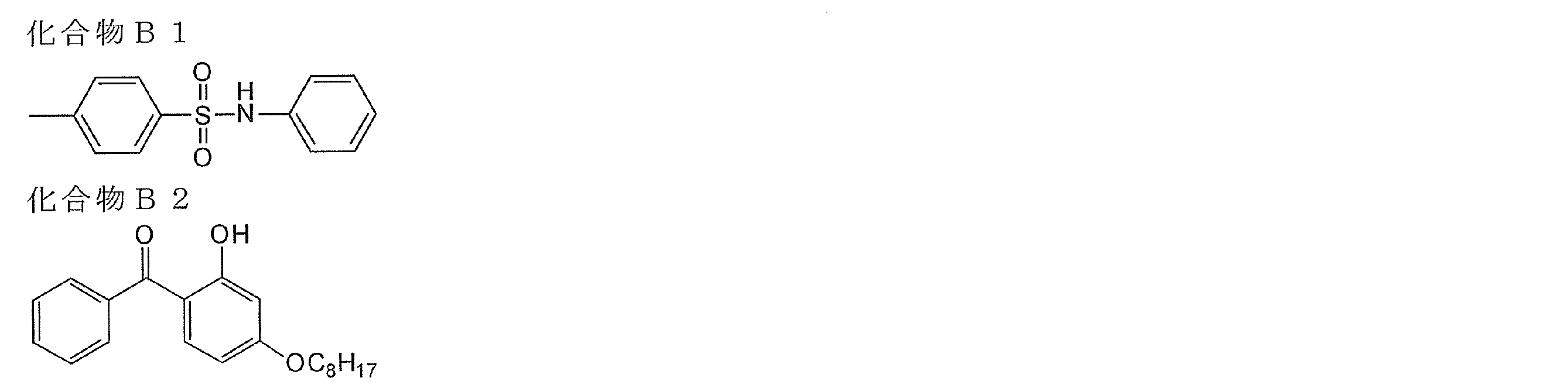
<セルロースアセテート保護フィルムの作製>
セルロースアシレート溶液Aを477質量部に、添加剤溶液Bの40質量部を添加し、充分に攪拌して、ドープを調製した。ドープを流延口から0℃に冷却したドラム上に流延した。溶媒含有率70質量%の場外で剥ぎ取り、フィルムの巾方向の両端をピンテンター(特開平4-1009号公報の図3に記載のピンテンター)で固定し、溶媒含有率が3乃至5質量%の状態で、横方向(機械方向に垂直な方向)の延伸率が3%となる間隔を保ちつつ乾燥した。その後、熱処理装置のロール間を搬送することにより、さらに乾燥し、厚み60μmのセルロースアセテート保護フィルムを作製した。保護フィルムの正面Reは2.0nmであった。
セルロースアシレート溶液Aを477質量部に、添加剤溶液Bの40質量部を添加し、充分に攪拌して、ドープを調製した。ドープを流延口から0℃に冷却したドラム上に流延した。溶媒含有率70質量%の場外で剥ぎ取り、フィルムの巾方向の両端をピンテンター(特開平4-1009号公報の図3に記載のピンテンター)で固定し、溶媒含有率が3乃至5質量%の状態で、横方向(機械方向に垂直な方向)の延伸率が3%となる間隔を保ちつつ乾燥した。その後、熱処理装置のロール間を搬送することにより、さらに乾燥し、厚み60μmのセルロースアセテート保護フィルムを作製した。保護フィルムの正面Reは2.0nmであった。
(直線偏光層の作製)
セルロースアセテート保護フィルムを、1.5規定の水酸化ナトリウム水溶液に、55℃で2分間浸漬した。室温の水洗浴槽中で洗浄し、30℃で0.1規定の硫酸を用いて中和した。再度、室温の水洗浴槽中で洗浄し、さらに100℃の温風で乾燥した。このようにして、セルロースアシレート保護フィルムの表面をケン化した。
続いて、厚さ80μmのロール状ポリビニルアルコールフィルムをヨウ素水溶液中で連続して5倍に延伸し、乾燥して直線偏光膜を得た。ポリビニルアルコール(クラレ製PVA-117H)3%水溶液を接着剤として、アルカリけん化処理したセルロースアシレート保護フィルムを2枚用意して直線偏光膜を間にして貼り合わせ、両面がセルロースアシレート保護フィルムによって保護された直線偏光層を得た。この際両側のセルロースアシレートフィルム保護フィルムの遅相軸が直線偏光膜の透過軸と平行になるように貼り付けた。
セルロースアセテート保護フィルムを、1.5規定の水酸化ナトリウム水溶液に、55℃で2分間浸漬した。室温の水洗浴槽中で洗浄し、30℃で0.1規定の硫酸を用いて中和した。再度、室温の水洗浴槽中で洗浄し、さらに100℃の温風で乾燥した。このようにして、セルロースアシレート保護フィルムの表面をケン化した。
続いて、厚さ80μmのロール状ポリビニルアルコールフィルムをヨウ素水溶液中で連続して5倍に延伸し、乾燥して直線偏光膜を得た。ポリビニルアルコール(クラレ製PVA-117H)3%水溶液を接着剤として、アルカリけん化処理したセルロースアシレート保護フィルムを2枚用意して直線偏光膜を間にして貼り合わせ、両面がセルロースアシレート保護フィルムによって保護された直線偏光層を得た。この際両側のセルロースアシレートフィルム保護フィルムの遅相軸が直線偏光膜の透過軸と平行になるように貼り付けた。
(1/4波長層の作製)
<光配向膜の作製>
前記直線偏光層の保護フィルムの表面に、下記構造の光配向材料E-1 1%水溶液をスピンコート塗布し、100℃で1分間乾燥した。得られた塗布膜に、空気下にて160W/cmの空冷メタルハライドランプ(アイグラフィックス(株)製)を用いて紫外線を照射する。このとき、ワイヤーグリッド偏光子(Moxtek社製, ProFlux PPL02)を図13(a)に示すように、方向1にセットして、さらにマスクA(画像パターンを有す石英露光マスク)を通して、露光を行う。その後、図13(b)に示すように、ワイヤーグリッド偏光子を方向2にセットして、さらにマスクBを通して、露光を行う。露光マスク面と光配向膜の間の距離を200μmに設定する。この際用いる紫外線の照度はUV-A領域(波長380nm~320nmの積算)において100mW/cm2、照射量はUV-A領域において1000mJ/cm2とする。
<光配向膜の作製>
前記直線偏光層の保護フィルムの表面に、下記構造の光配向材料E-1 1%水溶液をスピンコート塗布し、100℃で1分間乾燥した。得られた塗布膜に、空気下にて160W/cmの空冷メタルハライドランプ(アイグラフィックス(株)製)を用いて紫外線を照射する。このとき、ワイヤーグリッド偏光子(Moxtek社製, ProFlux PPL02)を図13(a)に示すように、方向1にセットして、さらにマスクA(画像パターンを有す石英露光マスク)を通して、露光を行う。その後、図13(b)に示すように、ワイヤーグリッド偏光子を方向2にセットして、さらにマスクBを通して、露光を行う。露光マスク面と光配向膜の間の距離を200μmに設定する。この際用いる紫外線の照度はUV-A領域(波長380nm~320nmの積算)において100mW/cm2、照射量はUV-A領域において1000mJ/cm2とする。

<1/4波長層の作製>
下記の1/4波長層用組成物を調製後、孔径0.2μmのポリプロピレン製フィルタでろ過して、1/4波長層用塗布液として用いる。該塗布液を塗布、膜面温度105℃で2分間乾燥して液晶相状態とした後、75℃まで冷却して、空気下にて160W/cmの空冷メタルハライドランプ(アイグラフィックス(株)製)を用いて紫外線を照射して、その配向状態を固定化して、厚さ1.3μmの、直線偏光層の偏光軸に対して、遅相軸が、各々、±45°にパターニングされた1/4波長層を作製する。得られた試料のチルト角は、ほぼ1°であり、測定波長550nmにおけるReは138nmであり、保護層とのRthの合計は13nmである。
下記の1/4波長層用組成物を調製後、孔径0.2μmのポリプロピレン製フィルタでろ過して、1/4波長層用塗布液として用いる。該塗布液を塗布、膜面温度105℃で2分間乾燥して液晶相状態とした後、75℃まで冷却して、空気下にて160W/cmの空冷メタルハライドランプ(アイグラフィックス(株)製)を用いて紫外線を照射して、その配向状態を固定化して、厚さ1.3μmの、直線偏光層の偏光軸に対して、遅相軸が、各々、±45°にパターニングされた1/4波長層を作製する。得られた試料のチルト角は、ほぼ1°であり、測定波長550nmにおけるReは138nmであり、保護層とのRthの合計は13nmである。
<1/4波長層用組成>
棒状液晶I-27 100質量部
水平配向剤A 0.3質量部
光重合開始剤 3.3質量部
(イルガキュア907、チバ・スペシャルティ・ケミカルズ(株)製)
増感剤(カヤキュア-DETX、日本化薬(株)製) 1.1質量部
メチルエチルケトン 300質量部
棒状液晶I-27 100質量部
水平配向剤A 0.3質量部
光重合開始剤 3.3質量部
(イルガキュア907、チバ・スペシャルティ・ケミカルズ(株)製)
増感剤(カヤキュア-DETX、日本化薬(株)製) 1.1質量部
メチルエチルケトン 300質量部
(立体画像用印画紙の作製)
<画像受像層の作製>
前記直線偏光層の1/4波長層の反対に位置するセルロースアセテート保護フィルム表面に、コロナ放電処理を施した後、ドデシルベンゼンスルホン酸ナトリウムを含むゼラチン下塗層を設けた。さらに下記組成の中間層Aをバーコーターにより塗布し乾燥した後、引き続いて下記組成の受容層Aをバーコーターにより塗布し乾燥させた。バーコーター塗布は40℃で行い、乾燥は各層50℃で16時間行った。それぞれの乾燥時の塗布量が中間層A:1.0g/m2、受容層A1:3.0g/m2となるように塗布を行った。
<画像受像層の作製>
前記直線偏光層の1/4波長層の反対に位置するセルロースアセテート保護フィルム表面に、コロナ放電処理を施した後、ドデシルベンゼンスルホン酸ナトリウムを含むゼラチン下塗層を設けた。さらに下記組成の中間層Aをバーコーターにより塗布し乾燥した後、引き続いて下記組成の受容層Aをバーコーターにより塗布し乾燥させた。バーコーター塗布は40℃で行い、乾燥は各層50℃で16時間行った。それぞれの乾燥時の塗布量が中間層A:1.0g/m2、受容層A1:3.0g/m2となるように塗布を行った。
<中間層A>
ポリエステル樹脂(バイロン200、商品名、東洋紡(株)製)10質量部
蛍光増白剤 1質量部
(Uvitex OB、商品名、チバ・スペシャルティ・ケミカルズ(株)製)
酸化チタン 30質量部
メチルエチルケトン/トルエン(質量比1/1) 90質量部
ポリエステル樹脂(バイロン200、商品名、東洋紡(株)製)10質量部
蛍光増白剤 1質量部
(Uvitex OB、商品名、チバ・スペシャルティ・ケミカルズ(株)製)
酸化チタン 30質量部
メチルエチルケトン/トルエン(質量比1/1) 90質量部
<受容層A>
ポリエステル樹脂 100質量部
(特開平2-265789号公報の実施例1-1に記載の樹脂)
アミノ変性シリコーン 5質量部
(信越化学工業(株)社製、商品名、X-22-3050C)
エポキシ変性シリコーン 5質量部
(信越化学工業(株)社製、商品名、X-22-300E)
メチルエチルケトン/トルエン(質量比1/1) 400質量部
ポリエステル樹脂 100質量部
(特開平2-265789号公報の実施例1-1に記載の樹脂)
アミノ変性シリコーン 5質量部
(信越化学工業(株)社製、商品名、X-22-3050C)
エポキシ変性シリコーン 5質量部
(信越化学工業(株)社製、商品名、X-22-300E)
メチルエチルケトン/トルエン(質量比1/1) 400質量部
(立体画像用印画紙)
この様にして、図6に示す構成と同様(但し、画像受像層12が、中間層Aと受容層Aとの積層体であり、中間層Aが保護層14a側に配置された積層体である)の構成の立体画像用印画紙を製造した。直線偏光層14の表面裏面に、各々、セルロースアセテート保護フィルム(14a、14b)が積層されており、さらに、観察者の視認側には、光配向膜15及びパターニングされた1/4波長層16が積層されており、且つ反対側には、中間層A及び受容層Aとの積層体である画像受像層12が配置されている、立体画像用印画紙を製造した。
この様にして、図6に示す構成と同様(但し、画像受像層12が、中間層Aと受容層Aとの積層体であり、中間層Aが保護層14a側に配置された積層体である)の構成の立体画像用印画紙を製造した。直線偏光層14の表面裏面に、各々、セルロースアセテート保護フィルム(14a、14b)が積層されており、さらに、観察者の視認側には、光配向膜15及びパターニングされた1/4波長層16が積層されており、且つ反対側には、中間層A及び受容層Aとの積層体である画像受像層12が配置されている、立体画像用印画紙を製造した。
(立体画像用インクシートの作製)
厚さ6.0μmのポリエステルフィルム(ルミラー、商品名、(株)東レ製)を基材フィルムとして用いた。そのフィルム背面側に耐熱スリップ層(厚み1μm)を形成し、かつ表面側に下記組成のイエロー、マゼンタ、シアン組成物を、それぞれ単色に塗布(乾膜時の塗布量1g/m2)した。
イエロー組成物
染料(マクロレックスイエロー6G、商品名、バイエル社製)5.5質量部
ポリビニルブチラール樹脂 4.5質量部
(エスレックBX-1、商品名、積水化学工業(株)製)
メチルエチルケトン/トルエン(質量比1/1) 90質量部
マゼンタ組成物
マゼンタ染料(ディスパーズレッド60) 5.5質量部
ポリビニルブチラール樹脂 4.5質量部
(エスレックBX-1、商品名、積水化学工業(株)製)
メチルエチルケトン/トルエン(質量比1/1) 90質量部
シアン組成物
シアン染料(ソルベントブルー63) 5.5質量部
ポリビニルブチラール樹脂 4.5質量部
(エスレックBX-1、商品名、積水化学工業(株)製)
メチルエチルケトン/トルエン(質量比1/1) 90質量部
厚さ6.0μmのポリエステルフィルム(ルミラー、商品名、(株)東レ製)を基材フィルムとして用いた。そのフィルム背面側に耐熱スリップ層(厚み1μm)を形成し、かつ表面側に下記組成のイエロー、マゼンタ、シアン組成物を、それぞれ単色に塗布(乾膜時の塗布量1g/m2)した。
イエロー組成物
染料(マクロレックスイエロー6G、商品名、バイエル社製)5.5質量部
ポリビニルブチラール樹脂 4.5質量部
(エスレックBX-1、商品名、積水化学工業(株)製)
メチルエチルケトン/トルエン(質量比1/1) 90質量部
マゼンタ組成物
マゼンタ染料(ディスパーズレッド60) 5.5質量部
ポリビニルブチラール樹脂 4.5質量部
(エスレックBX-1、商品名、積水化学工業(株)製)
メチルエチルケトン/トルエン(質量比1/1) 90質量部
シアン組成物
シアン染料(ソルベントブルー63) 5.5質量部
ポリビニルブチラール樹脂 4.5質量部
(エスレックBX-1、商品名、積水化学工業(株)製)
メチルエチルケトン/トルエン(質量比1/1) 90質量部
[立体画像印刷物の作製]
(右眼用及び左眼用画像形成)
前記インクシート及び前記印画紙を、日本電産コパル社製昇華型プリンターDPB1500(商品名)に装填可能なように加工し、高速プリントモードで右眼用画素は1/4波長層の右眼用部分に位置決めして画像を出力し、左眼用画素は1/4波長層の左眼用部分に位置決めして画像を出力し、立体画像印刷物を作製した。
(右眼用及び左眼用画像形成)
前記インクシート及び前記印画紙を、日本電産コパル社製昇華型プリンターDPB1500(商品名)に装填可能なように加工し、高速プリントモードで右眼用画素は1/4波長層の右眼用部分に位置決めして画像を出力し、左眼用画素は1/4波長層の左眼用部分に位置決めして画像を出力し、立体画像印刷物を作製した。
[立体画像の観察]
観察者が円偏光メガネを介して前記立体画像印刷物を観察したところ、クロストークやゴースト像のない鮮明な立体画像を観察することができた。なお、偏光メガネは、左眼用円偏光フィルタ及び右眼用円偏光フィルタから構成されており、各々の円偏光フィルタは、直線偏光フィルタと1/4λ位相差フィルムが、その偏光軸と遅相軸が45°の角度をなすように積層されており、且つ、左眼用と右眼用で、直線偏光フィルタの偏光軸が直交しているものを使用した。
観察者が円偏光メガネを介して前記立体画像印刷物を観察したところ、クロストークやゴースト像のない鮮明な立体画像を観察することができた。なお、偏光メガネは、左眼用円偏光フィルタ及び右眼用円偏光フィルタから構成されており、各々の円偏光フィルタは、直線偏光フィルタと1/4λ位相差フィルムが、その偏光軸と遅相軸が45°の角度をなすように積層されており、且つ、左眼用と右眼用で、直線偏光フィルタの偏光軸が直交しているものを使用した。
2.実施例1-2
[立体画像用印画紙の作製]
(画像受像層の作製)
実施例1-1で作製した直線偏光層の保護層の表面にコロナ放電処理を行なった後、下記画像受像層形成液と下記PAC液とを、それぞれ183g/m2、11.4g/m2の塗布量となるようにインラインブレンド後、エクストルージョンダイコーターで塗布を行った。その後、冷風乾燥機にて5℃、相対湿度30%(風速3~8m/sec)で5分処理後、更に25℃相対湿度25%(風速3~8m/sec)の乾燥風で20分間乾燥させた。これにより、保護層上に乾燥膜厚30μmの画像受像層を形成した。
[立体画像用印画紙の作製]
(画像受像層の作製)
実施例1-1で作製した直線偏光層の保護層の表面にコロナ放電処理を行なった後、下記画像受像層形成液と下記PAC液とを、それぞれ183g/m2、11.4g/m2の塗布量となるようにインラインブレンド後、エクストルージョンダイコーターで塗布を行った。その後、冷風乾燥機にて5℃、相対湿度30%(風速3~8m/sec)で5分処理後、更に25℃相対湿度25%(風速3~8m/sec)の乾燥風で20分間乾燥させた。これにより、保護層上に乾燥膜厚30μmの画像受像層を形成した。
<画像受像層形成液>
下記の「シリカ分散液」の組成に従って、イオン交換水にジメチルジアリルアンモニウムクロライド重合体(シャロールDC902P)を混合した液にシリカ微粒子を混合し、更に、ジルコゾールZA-30を添加したスラリーを、(株)スギノマシン社製、アルティマイザーで、170MPaで分散し、メジアン径(平均粒子径)120nmのシリカ分散液を調製した。
上記のシリカ分散液に下記「画像受像層形成液」の組成に従いイオン交換水、7.5%ホウ酸液、SC-505、ポリビニルアルコール溶解液、スーパーフレックス650-5を順次添加混合し、画像受像層形成液を調製した。
下記の「シリカ分散液」の組成に従って、イオン交換水にジメチルジアリルアンモニウムクロライド重合体(シャロールDC902P)を混合した液にシリカ微粒子を混合し、更に、ジルコゾールZA-30を添加したスラリーを、(株)スギノマシン社製、アルティマイザーで、170MPaで分散し、メジアン径(平均粒子径)120nmのシリカ分散液を調製した。
上記のシリカ分散液に下記「画像受像層形成液」の組成に従いイオン交換水、7.5%ホウ酸液、SC-505、ポリビニルアルコール溶解液、スーパーフレックス650-5を順次添加混合し、画像受像層形成液を調製した。
<シリカ分散液>
(1)気相法シリカ微粒子 15.0質量部
(日本アエロジル(株)製 AEROSIL300SF75)
(2)イオン交換水 82.9質量部
(3)シャロールDC-902P(51.5%溶液) 1.31質量部
(第一工業製薬(株)製 分散剤)
(4)酢酸ジルコニル 0.81質量部
(第一稀元素化学工業(株)製 ジルコゾールZA-30(50%溶液))
(1)気相法シリカ微粒子 15.0質量部
(日本アエロジル(株)製 AEROSIL300SF75)
(2)イオン交換水 82.9質量部
(3)シャロールDC-902P(51.5%溶液) 1.31質量部
(第一工業製薬(株)製 分散剤)
(4)酢酸ジルコニル 0.81質量部
(第一稀元素化学工業(株)製 ジルコゾールZA-30(50%溶液))
<画像受像層形成液>
(1)シリカ分散液 59.5質量部
(2)イオン交換水 7.8質量部
(3)7.5%ホウ酸液(架橋剤) 4.4質量部
(4)ジメチルアミン・エピクロルヒドリン・ポリアルキレンポリアミン重縮合物
(50%溶液)(ハイモ(株)製 SC-505) 0.1質量部
(5)下記ポリビニルアルコール溶解液 26.0質量部
(6)カチオン変性ポリウレタン 2.2質量部
(第一工業製薬(株)製 スーパーフレックス650-5(25%液))
(1)シリカ分散液 59.5質量部
(2)イオン交換水 7.8質量部
(3)7.5%ホウ酸液(架橋剤) 4.4質量部
(4)ジメチルアミン・エピクロルヒドリン・ポリアルキレンポリアミン重縮合物
(50%溶液)(ハイモ(株)製 SC-505) 0.1質量部
(5)下記ポリビニルアルコール溶解液 26.0質量部
(6)カチオン変性ポリウレタン 2.2質量部
(第一工業製薬(株)製 スーパーフレックス650-5(25%液))
<ポリビニルアルコール溶解液>
(1)ポリビニルアルコール 6.96質量部
(日本酢ビ・ポバール(株)製 JM-33、鹸化度94.3mol%、
重合度3300)
(2)ポリオキシエチレンラウリルエーテル 0.23質量部
(花王(株)製 界面活性剤 エマルゲン109P)
(3)ジエチレングリコールモノブチルエーテル 2.12質量部
(協和発酵(株)製 ブチセノール20P)
(4)イオン交換水 90.69質量部
(1)ポリビニルアルコール 6.96質量部
(日本酢ビ・ポバール(株)製 JM-33、鹸化度94.3mol%、
重合度3300)
(2)ポリオキシエチレンラウリルエーテル 0.23質量部
(花王(株)製 界面活性剤 エマルゲン109P)
(3)ジエチレングリコールモノブチルエーテル 2.12質量部
(協和発酵(株)製 ブチセノール20P)
(4)イオン交換水 90.69質量部
<PAC液>
(1)塩基度83%のポリ塩化アルミニウム水溶液 20質量部
(大明化学工業(株)製 アルファイン83)
(2)イオン交換水 80質量部
(1)塩基度83%のポリ塩化アルミニウム水溶液 20質量部
(大明化学工業(株)製 アルファイン83)
(2)イオン交換水 80質量部
この様にして、図6に示す構成と同様の構成の立体画像用印画紙を製造した。直線偏光層14の表面裏面に、各々、セルロースアセテート保護フィルム(14a、14b)が積層されており、さらに、観察者の視認側には、光配向膜15及びパターニングされた1/4波長層16が積層されており、且つ、反対側には、無機微粒子と水溶性高分子を含有する組成物からなる画像受像層12が配置されている、立体画像用印画紙を製造した。
[立体画像印刷物の作製]
左右二系統の撮影レンズを備えたデジタルカメラで撮影した、右眼用データ及び左眼用データを、各々、デジタルデータに変換したのち、インクジェット用インクをピエゾ方式のインクジェットヘッドを用いて、上記で得られた立体画像用印画紙の画像受像層に打滴し、右眼用画素及び左眼用画素を作製した。右眼用画素は1/4波長層の右眼用部分に位置決めして画像を出力し、左眼用画素は1/4波長層の左眼用部分に位置決めして画像を出力した。
左右二系統の撮影レンズを備えたデジタルカメラで撮影した、右眼用データ及び左眼用データを、各々、デジタルデータに変換したのち、インクジェット用インクをピエゾ方式のインクジェットヘッドを用いて、上記で得られた立体画像用印画紙の画像受像層に打滴し、右眼用画素及び左眼用画素を作製した。右眼用画素は1/4波長層の右眼用部分に位置決めして画像を出力し、左眼用画素は1/4波長層の左眼用部分に位置決めして画像を出力した。
[立体画像の観察]
観察者が円偏光メガネを介して前記立体画像印刷物を観察したところ、クロストークやゴースト像のない鮮明な立体画像を観察することができた。
観察者が円偏光メガネを介して前記立体画像印刷物を観察したところ、クロストークやゴースト像のない鮮明な立体画像を観察することができた。
3.実施例1-3
[立体画像用印画紙の作製]
(直線偏光層の作製)
実施例1-1で作製した保護層の表面に、クラレ社製ポリビニルアルコール「PVA103」の4%水溶液を、12番バーで塗布を行い、80℃で5分間乾燥させた。その後に、400rpmで3往復ラビング処理を行い、ラビング配向膜付保護層を作製した。
[立体画像用印画紙の作製]
(直線偏光層の作製)
実施例1-1で作製した保護層の表面に、クラレ社製ポリビニルアルコール「PVA103」の4%水溶液を、12番バーで塗布を行い、80℃で5分間乾燥させた。その後に、400rpmで3往復ラビング処理を行い、ラビング配向膜付保護層を作製した。
クロロホルム99質量部に下記構造のイエローアゾ色素A2-3(一般式(II)の化合物) 0.24質量部、下記構造のマゼンタアゾ色素A-46(一般式(I)の化合物) 0.33質量部、下記構造のシアンアゾ色素A3-1(一般式(III)の化合物) 0.37質量部、及び下記構造のスクアリリウム色素VI-5 0.06質量部を加え、撹拌溶解後、濾過して直線偏光層用塗布液を得た。次に、前記ラビング配向膜上に、該塗布液を塗布し、室温で自然乾燥して直線偏光層を作製した。得られた直線偏光層の厚さは0.4μmであり、二色比は42であった。また、直線偏光用組成物は、サーモトロピック液晶性を有しており、そのアイソトロピック相転移温度は240℃であった。




(酸素遮断層用塗布液の調製)
下記組成物をミキシングタンクに投入し、攪拌して酸素遮断層用塗布液とした。
ポリビニルアルコール(PVA205(商品名、クラレ(株)製)3.2質量部、ポリビニルピロリドン(PVP K-30(商品名、日本触媒(株)製)1.5質量部、メタノール44質量部、水56質量部を添加して攪拌した。孔径0.4μmのポリプロピレン製フィルタで濾過して酸素遮断層用塗布液を調製した。
下記組成物をミキシングタンクに投入し、攪拌して酸素遮断層用塗布液とした。
ポリビニルアルコール(PVA205(商品名、クラレ(株)製)3.2質量部、ポリビニルピロリドン(PVP K-30(商品名、日本触媒(株)製)1.5質量部、メタノール44質量部、水56質量部を添加して攪拌した。孔径0.4μmのポリプロピレン製フィルタで濾過して酸素遮断層用塗布液を調製した。
(酸素遮断層の作製)
前記記載の、直線偏光層の上層に、前記酸素遮断層用塗布液を塗布し、100℃で2分間乾燥し酸素遮断層を作製した。酸素遮断層の厚さは1μmであり、正面Reは0nmであった。
前記記載の、直線偏光層の上層に、前記酸素遮断層用塗布液を塗布し、100℃で2分間乾燥し酸素遮断層を作製した。酸素遮断層の厚さは1μmであり、正面Reは0nmであった。
(透明樹脂硬化層用塗布液の調製)
下記組成物をミキシングタンクに投入し、攪拌して透明樹脂硬化層塗布液とした。
トリメチロールプロパントリアクリレート(ビスコート#295(商品名、大阪有機化学(株)製)7.5質量部に、質量平均分子量15000のポリ(グリシジルメタクリレート)2.7質量部、メチルエチルケトン7.3質量部、シクロヘキサノン5.0質量部及び光重合開始剤(イルガキュア184(商品名)、チバ・スペシャルティ・ケミカルズ(株)製)0.5質量部を添加して攪拌した。孔径0.4μmのポリプロピレン製フィルタで濾過して透明樹脂硬化層用の塗布液を調製した。
下記組成物をミキシングタンクに投入し、攪拌して透明樹脂硬化層塗布液とした。
トリメチロールプロパントリアクリレート(ビスコート#295(商品名、大阪有機化学(株)製)7.5質量部に、質量平均分子量15000のポリ(グリシジルメタクリレート)2.7質量部、メチルエチルケトン7.3質量部、シクロヘキサノン5.0質量部及び光重合開始剤(イルガキュア184(商品名)、チバ・スペシャルティ・ケミカルズ(株)製)0.5質量部を添加して攪拌した。孔径0.4μmのポリプロピレン製フィルタで濾過して透明樹脂硬化層用の塗布液を調製した。
(透明樹脂硬化層用塗布液の作製)
前記酸素遮断層の上層に、該透明樹脂硬化層用塗布液を塗布し、100℃で2分間乾燥した。その後、窒素雰囲気下(酸素濃度100ppm以下)5Jの紫外線を照射して重合し、直線偏光層(層厚0.4μm)の表面に、層厚1μmの酸素遮断層、層厚2μmの透明樹脂硬化層が順次積層された積層体を作製した。透明樹脂硬化層の正面Reは0nmであった。
前記酸素遮断層の上層に、該透明樹脂硬化層用塗布液を塗布し、100℃で2分間乾燥した。その後、窒素雰囲気下(酸素濃度100ppm以下)5Jの紫外線を照射して重合し、直線偏光層(層厚0.4μm)の表面に、層厚1μmの酸素遮断層、層厚2μmの透明樹脂硬化層が順次積層された積層体を作製した。透明樹脂硬化層の正面Reは0nmであった。
(1/4波長層の作製)
前記透明樹脂硬化層の上層に、実施例1-1と同様の方法で1/4波長層を形成した。
前記透明樹脂硬化層の上層に、実施例1-1と同様の方法で1/4波長層を形成した。
(画像受像層の作製)
直線偏光層と反対側の保護層の表面に、実施例1-2と同様の方法で画像受像層を形成した。
直線偏光層と反対側の保護層の表面に、実施例1-2と同様の方法で画像受像層を形成した。
(立体画像用印画紙の作製)
この様にして、図6に示す構成と同様(但し、保護層14aと直線偏光層との間に配向膜が配置され、また保護層14bが、酸素遮断層及び透明樹脂硬化層の積層体である)の構成の立体画像用印画紙を製造した。塗布型直線偏光層12の一方の表面に、配向膜付きセルロースアセテート保護フィルム(14a)、及び他方の表面に酸素遮断層と透明硬化樹脂層の積層体(14b)が配置されており、さらに、観察者の視認側には、光配向膜15及びパターニングされた1/4波長層16が積層されており、且つ反対側には、無機微粒子と水溶性高分子を含有する組成物からなる画像受像層12が配置されている、立体画像用印画紙を製造した。
この様にして、図6に示す構成と同様(但し、保護層14aと直線偏光層との間に配向膜が配置され、また保護層14bが、酸素遮断層及び透明樹脂硬化層の積層体である)の構成の立体画像用印画紙を製造した。塗布型直線偏光層12の一方の表面に、配向膜付きセルロースアセテート保護フィルム(14a)、及び他方の表面に酸素遮断層と透明硬化樹脂層の積層体(14b)が配置されており、さらに、観察者の視認側には、光配向膜15及びパターニングされた1/4波長層16が積層されており、且つ反対側には、無機微粒子と水溶性高分子を含有する組成物からなる画像受像層12が配置されている、立体画像用印画紙を製造した。
[立体画像印刷物の作製]
実施例1-2と同様の方法で右眼用画素及び左眼用画素を作製した。
画像を形成した後、画像受像層の上層に、アルミ反射層を積層し、図17に示すのと同様の立体画像印刷物を製造した。
実施例1-2と同様の方法で右眼用画素及び左眼用画素を作製した。
画像を形成した後、画像受像層の上層に、アルミ反射層を積層し、図17に示すのと同様の立体画像印刷物を製造した。
[立体画像の観察]
観察者が円偏光メガネを介して前記立体画像印刷物を観察したところ、クロストークやゴースト像のない鮮明な立体画像を観察することができた。
観察者が円偏光メガネを介して前記立体画像印刷物を観察したところ、クロストークやゴースト像のない鮮明な立体画像を観察することができた。
4.実施例1-4
[立体画像用印刷物の作製]
保護層作製時の添加剤溶液Bから添加剤B1(Re低下剤)、及び添加剤B2(波長分散制御剤)を除いた以外は、実施例1-1と同様に立体画像用印刷物を作製した。このときの保護層(セルロースアセテート保護フィルム)の厚みは200μmであり、550nmにおけるRe値は15nm、Rthは85nmであった。
[立体画像の観察]
観察者が偏光メガネを介して前記立体画像印刷物を観察したところ立体画像は観察可能であったが、該保護層の高いReにより、若干のゴースト像が認識されてしまった。
[立体画像用印刷物の作製]
保護層作製時の添加剤溶液Bから添加剤B1(Re低下剤)、及び添加剤B2(波長分散制御剤)を除いた以外は、実施例1-1と同様に立体画像用印刷物を作製した。このときの保護層(セルロースアセテート保護フィルム)の厚みは200μmであり、550nmにおけるRe値は15nm、Rthは85nmであった。
[立体画像の観察]
観察者が偏光メガネを介して前記立体画像印刷物を観察したところ立体画像は観察可能であったが、該保護層の高いReにより、若干のゴースト像が認識されてしまった。
5.実施例1-5
[立体画像用印刷物の作製]
アルミ反射層を積層しない以外は、実施例1-3と同様に立体画像用印刷物を作製した。
[立体画像の観察]
観察者が円偏光メガネを介して前記立体画像印刷物を観察したところ、クロストークやゴースト像のない鮮明な立体画像を観察することができた。
また、観察者が円偏光メガネを介して前記立体画像印刷物を1/4波長層の0°の方向(図2に示す偏光軸cの方向)に30度傾けて観察したところ、若干のクロストークが認識されるものの、立体画像を観察することができた。
一方、実施例1-1の立体画像印刷物を同様に傾けて観察したところ、大きなクロストークを生じ、立体画像として認識することはできなかった。
塗布型偏光膜は、薄膜で偏光機能を発現できるため、前記立体画像印刷物は1/4波長層と画像受像層の間が約60μmと短くなっているのに対し、実施例1-1の立体画像印刷物は、偏光膜が延伸型のヨウ素偏光膜であるため、塗布型偏光膜に比べて厚膜である。そのため、1/4波長層と画像受像層の間が約140μm離れており、傾けた際により大きな視差を生じる。そのため、大きなクロストークが発生したと考えられる。
[立体画像用印刷物の作製]
アルミ反射層を積層しない以外は、実施例1-3と同様に立体画像用印刷物を作製した。
[立体画像の観察]
観察者が円偏光メガネを介して前記立体画像印刷物を観察したところ、クロストークやゴースト像のない鮮明な立体画像を観察することができた。
また、観察者が円偏光メガネを介して前記立体画像印刷物を1/4波長層の0°の方向(図2に示す偏光軸cの方向)に30度傾けて観察したところ、若干のクロストークが認識されるものの、立体画像を観察することができた。
一方、実施例1-1の立体画像印刷物を同様に傾けて観察したところ、大きなクロストークを生じ、立体画像として認識することはできなかった。
塗布型偏光膜は、薄膜で偏光機能を発現できるため、前記立体画像印刷物は1/4波長層と画像受像層の間が約60μmと短くなっているのに対し、実施例1-1の立体画像印刷物は、偏光膜が延伸型のヨウ素偏光膜であるため、塗布型偏光膜に比べて厚膜である。そのため、1/4波長層と画像受像層の間が約140μm離れており、傾けた際により大きな視差を生じる。そのため、大きなクロストークが発生したと考えられる。
6.実施例1-6
[立体画像用印刷物の作製]
直線偏光層作製時の直線偏光層用組成物を、下記組成に変更した以外は、実施例1-3と同様に立体画像用印刷物を作製した。このときの直線偏光層の厚みは0.4μmであり、二色比は37であった。
[立体画像用印刷物の作製]
直線偏光層作製時の直線偏光層用組成物を、下記組成に変更した以外は、実施例1-3と同様に立体画像用印刷物を作製した。このときの直線偏光層の厚みは0.4μmであり、二色比は37であった。
<直線偏光層用組成物>
(1)イエローアゾ色素A2-3 0.2質量部
(2)マゼンタアゾ色素C-9 0.4質量部
(3)シアンアゾ色素A3-1 0.4質量部
(4)クロロホルム 99質量部
(1)イエローアゾ色素A2-3 0.2質量部
(2)マゼンタアゾ色素C-9 0.4質量部
(3)シアンアゾ色素A3-1 0.4質量部
(4)クロロホルム 99質量部

[立体画像の観察]
観察者が円偏光メガネを介して前記立体画像印刷物を観察したところ、クロストークやゴースト像のない鮮明な立体画像を観察することができた。
観察者が円偏光メガネを介して前記立体画像印刷物を観察したところ、クロストークやゴースト像のない鮮明な立体画像を観察することができた。
7.実施例1-7
[立体画像用印画物の作製]
直線偏光層作製時の直線偏光層用組成物を、下記組成に変更した以外は、実施例1-3と同様に立体画像用印刷物を作製した。このときの直線偏光層の厚みは0.8μmであり、二色比は71であった。
[立体画像用印画物の作製]
直線偏光層作製時の直線偏光層用組成物を、下記組成に変更した以外は、実施例1-3と同様に立体画像用印刷物を作製した。このときの直線偏光層の厚みは0.8μmであり、二色比は71であった。
<直線偏光層用組成物>
(1)マゼンタアゾ色素A-16 1.2質量部
(2)マゼンタアゾ色素B-4 0.8質量部
(3)クロロホルム 98質量部
(1)マゼンタアゾ色素A-16 1.2質量部
(2)マゼンタアゾ色素B-4 0.8質量部
(3)クロロホルム 98質量部


観察者が円偏光メガネを介して前記立体画像印刷物を観察したところ、クロストークやゴースト像のない鮮明な立体画像を観察することができた。
8.実施例1-8
実施例1-1で作製した保護層の表面に、実施例1-1と同様の操作にて光配向膜及び1/4波長層を順次形成した。得られた1/4波長層の各々の遅相軸は直交しており、チルト角は、ほぼ1°であり、測定波長550nmにおけるReは138nmであり、保護層とのRthの合計は13nmであった。また、1/4波長層の膜厚は1.3μmであった。
実施例1-1で作製した保護層の表面に、実施例1-1と同様の操作にて光配向膜及び1/4波長層を順次形成した。得られた1/4波長層の各々の遅相軸は直交しており、チルト角は、ほぼ1°であり、測定波長550nmにおけるReは138nmであり、保護層とのRthの合計は13nmであった。また、1/4波長層の膜厚は1.3μmであった。
次に、1/4波長層の表面に、クラレ社製ポリビニルアルコール「PVA103」の4%水溶液を、12番バーで塗布を行い、80℃で5分間乾燥させた。その後に、1/4波長層の遅相軸と±45°の角度をなすように400rpmで3往復ラビング処理を行い、ラビング配向膜付1/4波長層を作製した。
次に、実施例1-3で調製した直線偏光層用塗布液を前記ラビング配向膜上に塗布し、室温で自然乾燥して直線偏光層を作製した。得られた直線偏光層の厚さは0.4μmであり、二色比は42であった。また、該直線偏光層の偏光軸に対して、1/4波長層の遅相軸は、各々、±45°にパターニングされていた。
次に、実施例1-3と同様の手順にて、酸素遮断層及び透明樹脂硬化層を順次積層した。酸素遮断層及び透明樹脂硬化層の層厚は、それぞれ、1μm及び2μmであった。また、各々の層の正面Reは、いずれも0nmであった。
前記透明樹脂硬化層の表面に、実施例1-3と同様の方法で画像受像層を形成した後、実施例1-3と同様の方法で立体画像印刷物を作製した。なお、アルミ反射層は積層しなかった。
[立体画像の観察]
観察者が円偏光メガネを介して前記立体画像印刷物を観察したところ、クロストークやゴースト像のない鮮明な立体画像を観察することができた。
また、観察者が円偏光メガネを介して前記立体画像印刷物をパターニングされた位相差層の0°の方向(図2に示す偏光軸cの方向)に30度傾けて観察しても、ほとんどクロストークが認識されず、鮮明な立体画像を観察することができた。
前記立体画像印刷物は、塗布型偏光膜が薄膜であっても偏光機能を発現でき、パターニングされた位相差層と画像受像層の間が5μm以下と極めて短くなっているため、クロストークが発生しないと考えられる。
[立体画像の観察]
観察者が円偏光メガネを介して前記立体画像印刷物を観察したところ、クロストークやゴースト像のない鮮明な立体画像を観察することができた。
また、観察者が円偏光メガネを介して前記立体画像印刷物をパターニングされた位相差層の0°の方向(図2に示す偏光軸cの方向)に30度傾けて観察しても、ほとんどクロストークが認識されず、鮮明な立体画像を観察することができた。
前記立体画像印刷物は、塗布型偏光膜が薄膜であっても偏光機能を発現でき、パターニングされた位相差層と画像受像層の間が5μm以下と極めて短くなっているため、クロストークが発生しないと考えられる。
9.実施例1-9
[立体画像用画像受像フィルムの作製]
(画像受像層の作製)
下記組成中の(1)沈降法シリカ微粒子と(2)イオン交換水と(3)「シャロールDC-902P」と(4)「ZA-30」とを混合し、超音波分散機〔(株)エスエムテー製〕を用いて分散させた後、得られた分散液を45℃に加熱して20時間保持した。その後これに、(5)ホウ酸と(6)ポリビニルアルコール溶解液と(7)スーパーフレックス650と(8)エタノールとを30℃下で加え、画像受像層用塗布液Aを調製した。
[立体画像用画像受像フィルムの作製]
(画像受像層の作製)
下記組成中の(1)沈降法シリカ微粒子と(2)イオン交換水と(3)「シャロールDC-902P」と(4)「ZA-30」とを混合し、超音波分散機〔(株)エスエムテー製〕を用いて分散させた後、得られた分散液を45℃に加熱して20時間保持した。その後これに、(5)ホウ酸と(6)ポリビニルアルコール溶解液と(7)スーパーフレックス650と(8)エタノールとを30℃下で加え、画像受像層用塗布液Aを調製した。
<画像受像層用塗布液Aの組成>
(1)沈降法シリカ微粒子(無機微粒子) 10.0部
(P-78A(粒径7.7μm)とP-604(粒径0.64μm)とを75:25[質量比]にて混合;いずれも水澤化学工業(株)製;以下、シリカ微粒子という。)
(2)イオン交換水 62.8部
(3)シャロールDC-902P(51.5%水溶液) 0.87部
(分散剤、第一工業製薬(株)製)
(4)ZA-30(酢酸ジルコニル) 0.54部
(第一稀元素化学工業(株)製)
(5)ホウ酸(架橋剤) 0.44部
(6)ポリビニルアルコール(水溶性樹脂)溶解液 34.9部
-組成-
・PVA-235 2.43部
(鹸化度88%、重合度3500(株)クラレ製)
・ポリオキシエチレンラウリルエーテル 0.08部
(エマルゲン109P(10%水溶液)、HLB値13.6、花王(株)製;界面活性剤)
・ジエチレングリコールモノブチルエーテル 0.74部
(ブチセノール20P、協和発酵(株)製)
・イオン交換水 31.0部
(7)スーパーフレックス650(25%水分散液) 2.47部
(第一工業製薬(株)製)
(8)エタノール 1.3部
(1)沈降法シリカ微粒子(無機微粒子) 10.0部
(P-78A(粒径7.7μm)とP-604(粒径0.64μm)とを75:25[質量比]にて混合;いずれも水澤化学工業(株)製;以下、シリカ微粒子という。)
(2)イオン交換水 62.8部
(3)シャロールDC-902P(51.5%水溶液) 0.87部
(分散剤、第一工業製薬(株)製)
(4)ZA-30(酢酸ジルコニル) 0.54部
(第一稀元素化学工業(株)製)
(5)ホウ酸(架橋剤) 0.44部
(6)ポリビニルアルコール(水溶性樹脂)溶解液 34.9部
-組成-
・PVA-235 2.43部
(鹸化度88%、重合度3500(株)クラレ製)
・ポリオキシエチレンラウリルエーテル 0.08部
(エマルゲン109P(10%水溶液)、HLB値13.6、花王(株)製;界面活性剤)
・ジエチレングリコールモノブチルエーテル 0.74部
(ブチセノール20P、協和発酵(株)製)
・イオン交換水 31.0部
(7)スーパーフレックス650(25%水分散液) 2.47部
(第一工業製薬(株)製)
(8)エタノール 1.3部
表面がゼラチンで下塗りされた、厚み175μmの二軸延伸ポリエチレンテレフタレートフィルムの下塗り面に、上記より得た画像受像層用塗布液Aを塗布量が204ml/m2となるように塗布した。このとき、8質量%のポリ塩化アルミ水溶液(アルファイン83;大明化学工業(株)製)を画像受像層用塗布液Aに予め、塗布量が12.0ml/m2となるように塗布直前に混合しておいた。
塗布後、熱風乾燥機にて80℃(風速3~8m/秒)にて塗布膜の固形分濃度が20%になるまで乾燥させた。この間、塗布膜は恒率乾燥を示した。そして、この塗布膜を、減率乾燥を示す前に下記組成の塩基性溶液Cに3秒浸漬し、塗布膜上にその13g/m2を付着させ、更に80℃下で10分間乾燥させた。以上のようにして、乾燥層厚33μmの立体画像用画像受像フィルムを作製した。
<塩基性溶液Cの組成>
(1)ホウ酸 0.65部
(2)炭酸ジルコニルアンモニウム 2.5部
(ジルコゾールAC-7(28%水溶液)、第一稀元素化学工業(株)製)
(3)炭酸アンモニウム(一級;関東化学(株)製) 3.5部
(4)イオン交換水 63.3部
(5)ポリオキシエチレンラウリルエーテル(界面活性剤) 30.0部
(花王(株)製、エマルゲン109P(2%水溶液)、HLB値13.6)
<塩基性溶液Cの組成>
(1)ホウ酸 0.65部
(2)炭酸ジルコニルアンモニウム 2.5部
(ジルコゾールAC-7(28%水溶液)、第一稀元素化学工業(株)製)
(3)炭酸アンモニウム(一級;関東化学(株)製) 3.5部
(4)イオン交換水 63.3部
(5)ポリオキシエチレンラウリルエーテル(界面活性剤) 30.0部
(花王(株)製、エマルゲン109P(2%水溶液)、HLB値13.6)
[立体画像用画像受像フィルムへの印字]
左右二系統の撮影レンズを備えたデジタルカメラで撮影した、右眼用データ及び左眼用データを、各々、デジタルデータに変換したのち、インクジェット用インクをピエゾ方式のインクジェットヘッドを用いて、上記立体画像用印画紙の画像受像層に打滴し、右眼用画素及び左眼用画素を作製した。右眼用画素及び左眼用画素は、254μmごとに交互に入れ替えた横ストライプ形状として画像を出力した。
左右二系統の撮影レンズを備えたデジタルカメラで撮影した、右眼用データ及び左眼用データを、各々、デジタルデータに変換したのち、インクジェット用インクをピエゾ方式のインクジェットヘッドを用いて、上記立体画像用印画紙の画像受像層に打滴し、右眼用画素及び左眼用画素を作製した。右眼用画素及び左眼用画素は、254μmごとに交互に入れ替えた横ストライプ形状として画像を出力した。
[立体画像用印刷物の作製]
<1/4波長層の作製>
実施例1-1で作製したセルロースアセテート保護フィルム表面に、クラレ社製ポリビニルアルコール「PVA103」の4%水溶液を、12番バーで塗布を行い、80℃で5分間乾燥させた。その後に、400rpmで一方向に1往復、ラビング処理を行い、ラビング配向膜付透明支持体を作製した。
<1/4波長層の作製>
実施例1-1で作製したセルロースアセテート保護フィルム表面に、クラレ社製ポリビニルアルコール「PVA103」の4%水溶液を、12番バーで塗布を行い、80℃で5分間乾燥させた。その後に、400rpmで一方向に1往復、ラビング処理を行い、ラビング配向膜付透明支持体を作製した。
下記組成の1/4波長層用組成物を調製後、孔径0.2μmのポリプロピレン製フィルタでろ過して、1/4波長層用塗布液として用いる。該塗布液を塗布、膜面温度80℃で1分間乾燥して液晶相状態とし均一配向させた後、室温まで冷却した。次に、横ストライプ幅254μmのマスクを1/4波長層用塗布液を塗布した基板上に配置し、空気下にて20mW/cm2の空冷メタルハライドランプ(アイグラフィックス(株)製)を用いて紫外線を5秒間照射して、その配向状態を固定化することにより第1位相差領域を形成した。続いて、膜面温度140℃まで昇温し、一旦等方相にした後、100℃まで降温し、その温度で1分間加熱して均一配向させた。室温まで冷却した後、20mW/cm2で20秒間全面照射して、その配向状態を固定化することにより第2位相差領域を形成した。この様にして遅相軸が直交したパターニング1/4波長層を作製した。膜厚は、0.8μmであり、チルト角は、ほぼ90°であり、測定波長550nmにおけるReは138nmであり、保護層とのRthの合計は-36nmである。
<1/4波長層用組成物の組成>
ディスコティック液晶E-1 100質量部
配向膜界面配向剤(II-1) 1.0質量部
空気界面配向剤(P-1) 0.4質量部
光重合開始剤 3.0質量部
(イルガキュア907、チバ・スペシャルティ・ケミカルズ(株)製)
増感剤(カヤキュア-DETX、日本化薬(株)製) 1.0質量部
メチルエチルケトン 300質量部
ディスコティック液晶E-1 100質量部
配向膜界面配向剤(II-1) 1.0質量部
空気界面配向剤(P-1) 0.4質量部
光重合開始剤 3.0質量部
(イルガキュア907、チバ・スペシャルティ・ケミカルズ(株)製)
増感剤(カヤキュア-DETX、日本化薬(株)製) 1.0質量部
メチルエチルケトン 300質量部
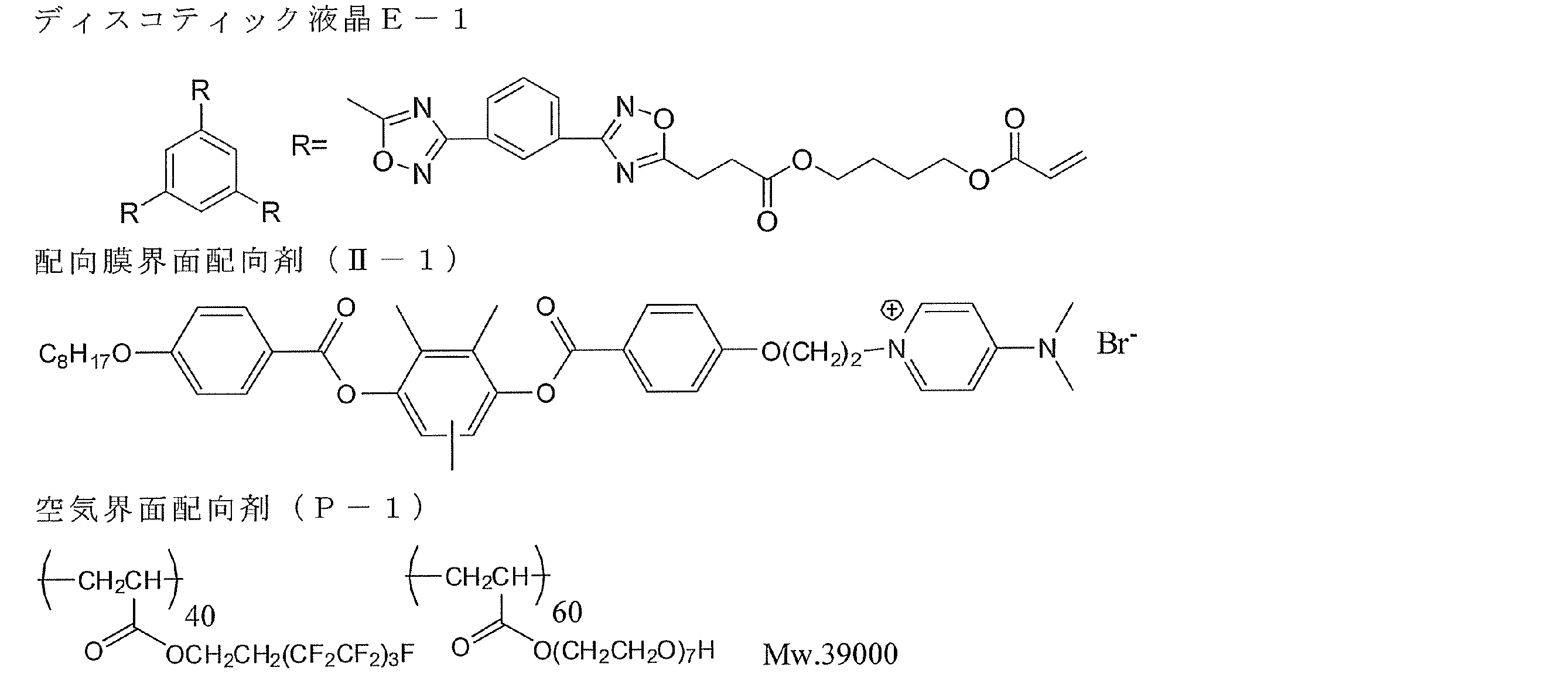
<直線偏光層の作製>
厚さ80μmのポリビニルアルコールフィルムをヨウ素水溶液中で5倍に延伸し、乾燥して厚さ30μmの直線偏光層を得た。
厚さ80μmのポリビニルアルコールフィルムをヨウ素水溶液中で5倍に延伸し、乾燥して厚さ30μmの直線偏光層を得た。
<パターニング1/4波長層と直線偏光層の積層>
上記パターニング1/4波長層の1/4波長層側に偏光層がくるように粘着剤で貼り付け、更に偏光層のもう一方の側に実施例1-1で作製したセルロースアセテート保護フィルムをアルカリケン化処理を行った後、粘着剤剤を塗設してから貼り合わせ、パターニング1/4波長層と偏光層を積層した。なお、直線偏光層の偏光軸が、パターニング1/4波長層の遅相軸と、各々、±45°となるように貼合せを行い、粘着剤層の厚みは16μmであった。
上記パターニング1/4波長層の1/4波長層側に偏光層がくるように粘着剤で貼り付け、更に偏光層のもう一方の側に実施例1-1で作製したセルロースアセテート保護フィルムをアルカリケン化処理を行った後、粘着剤剤を塗設してから貼り合わせ、パターニング1/4波長層と偏光層を積層した。なお、直線偏光層の偏光軸が、パターニング1/4波長層の遅相軸と、各々、±45°となるように貼合せを行い、粘着剤層の厚みは16μmであった。
<直線偏光層と立体画像用画像受像フィルムとの積層>
上記で作製したパターニング1/4波長層付直線偏光層を粘着剤を用いて立体画像用画像受像フィルムと貼り合わせた。なお貼合は、パターニング1/4波長層のストライプと立体画像用画像受像フィルムに印字したストライプとが一致するように貼合せを行い、粘着剤層の厚みは16μmであった。
この様にして、図8に示す構成と同様の立体画像印刷物を得た。
上記で作製したパターニング1/4波長層付直線偏光層を粘着剤を用いて立体画像用画像受像フィルムと貼り合わせた。なお貼合は、パターニング1/4波長層のストライプと立体画像用画像受像フィルムに印字したストライプとが一致するように貼合せを行い、粘着剤層の厚みは16μmであった。
この様にして、図8に示す構成と同様の立体画像印刷物を得た。
[立体画像の観察]
観察者が円偏光メガネを介して前記立体画像印刷物を観察したところ、クロストークやゴースト像のない鮮明な立体画像を観察することができた。
また、観察者が円偏光メガネを介して前記立体画像印刷物をパターニングされた位相差層の0°の方向(図2に示す偏光軸cの方向)に30度傾けて観察しても、ほとんどクロストークが認識されず、鮮明な立体画像を観察することができた。
前記立体画像印刷物は、パターニング1/4波長層と画像受像層の距離dは122μmであり、パターン幅pは254μmであり、d/pは0.48であるためクロストークが発生しないと考えられる。
観察者が円偏光メガネを介して前記立体画像印刷物を観察したところ、クロストークやゴースト像のない鮮明な立体画像を観察することができた。
また、観察者が円偏光メガネを介して前記立体画像印刷物をパターニングされた位相差層の0°の方向(図2に示す偏光軸cの方向)に30度傾けて観察しても、ほとんどクロストークが認識されず、鮮明な立体画像を観察することができた。
前記立体画像印刷物は、パターニング1/4波長層と画像受像層の距離dは122μmであり、パターン幅pは254μmであり、d/pは0.48であるためクロストークが発生しないと考えられる。
10.実施例1-10
[立体画像用画像受像フィルムの作製]
実施例1-9と同様の方法にて、立体画像用画像受像フィルムを作製した後、同様に印字を行った。
[立体画像用画像受像フィルムの作製]
実施例1-9と同様の方法にて、立体画像用画像受像フィルムを作製した後、同様に印字を行った。
[立体画像用印刷物の作製]
<1/4波長層の作製>
(1)平行配向膜(第一の配向膜)の作製
実施例1-1で作製したセルロースアセテート保護フィルムの表面に、クラレ社製ポリビニルアルコール「PVA103」の4%水/メタノール溶液(PVA-103(4.0g)を水72g及びメタノール24gに溶解させた、粘度4.35cp、表面張力44.8dyne)を、12番バーで塗布を行い、80℃で5分間乾燥させた。
<1/4波長層の作製>
(1)平行配向膜(第一の配向膜)の作製
実施例1-1で作製したセルロースアセテート保護フィルムの表面に、クラレ社製ポリビニルアルコール「PVA103」の4%水/メタノール溶液(PVA-103(4.0g)を水72g及びメタノール24gに溶解させた、粘度4.35cp、表面張力44.8dyne)を、12番バーで塗布を行い、80℃で5分間乾燥させた。
(2)パターニング直交配向膜(第二の配向膜)の作製
和光純薬製ポリアクリル酸(Mw25000)2.0gをトリエチルアミン2.52g/水1.12g/プロパノール5.09g/3-メトキシ-1-ブタノール5.09gに溶解させ、塗布液を調製した。
和光純薬製ポリアクリル酸(Mw25000)2.0gをトリエチルアミン2.52g/水1.12g/プロパノール5.09g/3-メトキシ-1-ブタノール5.09gに溶解させ、塗布液を調製した。
次に、フレキソ版として、図18に示す形状の凹凸を有する合成ゴム状フレキソ版を作製した。
図18に記載のフレキソ印刷装置として、フレキシプルーフ100(RK Print Coat Instruments Ltd. UK)を使用した。アニロックスローラ13はセル400線/cm(容積3cm3/m2)を使用した。上記フレキソ版をフレキシプルーフ100の圧胴に感圧テープをつけて貼り合わせた。印圧ローラに前記平行配向膜を貼り付けた後、前記パターニング直交配向膜用塗布液をドクターブレードに入れ、印刷速度30m/minで直交配向膜を平行配向膜の上にパターン印刷した。
(3)ラビング配向層の作製
80℃で5分間乾燥させた後に、1000rpmで一方向に1往復、ラビング処理を行い、ラビング配向層を作製した。
80℃で5分間乾燥させた後に、1000rpmで一方向に1往復、ラビング処理を行い、ラビング配向層を作製した。
実施例1-9と同様にして、1/4波長層用塗布液を調製し、該塗布液を塗布、膜面温度110℃で1分間乾燥して液晶相状態とした後、80℃まで冷却して、空気下にて160W/cmの空冷メタルハライドランプ(アイグラフィックス(株)製)を用いて紫外線を照射して、その配向状態を固定化して、厚さ0.8μmの遅相軸が直交したパターニング1/4波長層を作製した。各々のチルト角は、ほぼ90°であり、測定波長550nmにおけるReは138nmであり、保護層とのRthの合計は-36nmである。
<直線偏光層の作製>
厚さ80μmのポリビニルアルコールフィルムをヨウ素水溶液中で5倍に延伸し、乾燥して厚さ30μmの直線偏光層を得た。
厚さ80μmのポリビニルアルコールフィルムをヨウ素水溶液中で5倍に延伸し、乾燥して厚さ30μmの直線偏光層を得た。
<パターニング1/4波長層と直線偏光層の積層>
上記のパターニング1/4波長層の1/4波長層側に偏光層がくるように粘着剤で貼り付けパターニング1/4波長層と偏光層を積層した。なお、直線偏光層の偏光軸が、パターニング1/4波長層の遅相軸と、各々、±45°となるように貼合せを行い、粘着剤層の厚みは16μmであった。
上記のパターニング1/4波長層の1/4波長層側に偏光層がくるように粘着剤で貼り付けパターニング1/4波長層と偏光層を積層した。なお、直線偏光層の偏光軸が、パターニング1/4波長層の遅相軸と、各々、±45°となるように貼合せを行い、粘着剤層の厚みは16μmであった。
<直線偏光層と立体画像用画像受像フィルムとの積層>
上記で作製したパターニング1/4波長層付直線偏光層を粘着剤を用いて、立体画像用画像受像フィルムと貼り合わせた。なお貼合は、パターニング1/4波長層のストライプと立体画像用画像受像フィルムに印字したストライプが一致するように貼合せを行い、粘着剤層の厚みは16μmであった。
この様にして、図9に示す構成と同様の立体画像印刷物を得た。
上記で作製したパターニング1/4波長層付直線偏光層を粘着剤を用いて、立体画像用画像受像フィルムと貼り合わせた。なお貼合は、パターニング1/4波長層のストライプと立体画像用画像受像フィルムに印字したストライプが一致するように貼合せを行い、粘着剤層の厚みは16μmであった。
この様にして、図9に示す構成と同様の立体画像印刷物を得た。
[立体画像の観察]
観察者が円偏光メガネを介して前記立体画像印刷物を観察したところ、クロストークやゴースト像のない鮮明な立体画像を観察することができた。
また、観察者が円偏光メガネを介して前記立体画像印刷物をパターニングされた1/4波長層の0°の方向(図2に示す偏光軸cの方向)に30度傾けて観察しても、ほとんどクロストークが認識されず、鮮明な立体画像を観察することができた。
前記立体画像印刷物は、パターニング1/4波長層と画像受像層の距離dは62μmであり、パターン幅pは254μmであり、d/pは0.24であるためクロストークが発生しないと考えられる。
観察者が円偏光メガネを介して前記立体画像印刷物を観察したところ、クロストークやゴースト像のない鮮明な立体画像を観察することができた。
また、観察者が円偏光メガネを介して前記立体画像印刷物をパターニングされた1/4波長層の0°の方向(図2に示す偏光軸cの方向)に30度傾けて観察しても、ほとんどクロストークが認識されず、鮮明な立体画像を観察することができた。
前記立体画像印刷物は、パターニング1/4波長層と画像受像層の距離dは62μmであり、パターン幅pは254μmであり、d/pは0.24であるためクロストークが発生しないと考えられる。
11.実施例1-11
[立体画像用画像受像フィルムの作製]
実施例1-9と同様の方法にて、立体画像用画像受像フィルムを作製した後、同様に印字を行った。
[立体画像用画像受像フィルムの作製]
実施例1-9と同様の方法にて、立体画像用画像受像フィルムを作製した後、同様に印字を行った。
[立体画像用印刷物の作製]
<直線偏光層の作製>
実施例1-10で作製したパターニング1/4波長層の上層に、クラレ社製ポリビニルアルコール「PVA103」の4%水/メタノール溶液(PVA-103(4.0g)を水72g及びメタノール24gに溶解させた、粘度4.35cp、表面張力44.8dyne)を、12番バーで塗布を行い、80℃で5分間乾燥させた後、400rpmで1方向に3往復、ラビング処理を行い、ラビング配向層付パターニング1/4波長層を作製した。配向層の厚みは0.9μmであり、ラビング方向は、パターニング1/4波長層の遅相軸と、各々、±45°となる方向に実施した。
<直線偏光層の作製>
実施例1-10で作製したパターニング1/4波長層の上層に、クラレ社製ポリビニルアルコール「PVA103」の4%水/メタノール溶液(PVA-103(4.0g)を水72g及びメタノール24gに溶解させた、粘度4.35cp、表面張力44.8dyne)を、12番バーで塗布を行い、80℃で5分間乾燥させた後、400rpmで1方向に3往復、ラビング処理を行い、ラビング配向層付パターニング1/4波長層を作製した。配向層の厚みは0.9μmであり、ラビング方向は、パターニング1/4波長層の遅相軸と、各々、±45°となる方向に実施した。
実施例1-2で調製した直線偏光層用塗布液を、前記ラビング配向層付パターニング1/4波長層上に塗布し、室温で自然乾燥して直線偏光層を積層した。得られた直線偏光層の厚さは0.4μmであり、二色比は42であった。また、直線偏光層の偏光軸は、パターニング1/4波長層の遅相軸と、各々、±45°であった。
<直線偏光層と立体画像用画像受像フィルとの積層>
上記で作製したパターニング1/4波長層付直線偏光層を粘着剤を用いて、立体画像用画像受像フィルムと貼り合わせた。なお貼合は、パターニング1/4波長層のストライプと立体画像用画像受像フィルムに印字したストライプが一致するように貼合せを行い、粘着剤層の厚みは16μmであった。
この様にして、図11に示す構成と同様の立体画像印刷物を得た。
上記で作製したパターニング1/4波長層付直線偏光層を粘着剤を用いて、立体画像用画像受像フィルムと貼り合わせた。なお貼合は、パターニング1/4波長層のストライプと立体画像用画像受像フィルムに印字したストライプが一致するように貼合せを行い、粘着剤層の厚みは16μmであった。
この様にして、図11に示す構成と同様の立体画像印刷物を得た。
[立体画像の観察]
観察者が円偏光メガネを介して前記立体画像印刷物を観察したところ、クロストークやゴースト像のない鮮明な立体画像を観察することができた。
また、観察者が円偏光メガネを介して前記立体画像印刷物をパターニングされた1/4波長層の0°の方向(図2に示す偏光軸cの方向)に30度傾けて観察しても、ほとんどクロストークが認識されず、鮮明な立体画像を観察することができた。
前記立体画像印刷物は、パターニング1/4波長層と画像受像層の距離dは17.7μmであり、パターン幅pは254μmであり、d/pは0.07であるためクロストークが発生しないと考えられる。
観察者が円偏光メガネを介して前記立体画像印刷物を観察したところ、クロストークやゴースト像のない鮮明な立体画像を観察することができた。
また、観察者が円偏光メガネを介して前記立体画像印刷物をパターニングされた1/4波長層の0°の方向(図2に示す偏光軸cの方向)に30度傾けて観察しても、ほとんどクロストークが認識されず、鮮明な立体画像を観察することができた。
前記立体画像印刷物は、パターニング1/4波長層と画像受像層の距離dは17.7μmであり、パターン幅pは254μmであり、d/pは0.07であるためクロストークが発生しないと考えられる。
12.比較例1-1
画像受像層12を形成しなかった以外は、実施例1-2で作製したのと同様の構成の積層体を作製した。
直線偏光層の1/4波長層と反対側に積層されたセルロースアセテート保護フィルムの表面に、実施例1-1と同様に感熱転写法で、及び実施例1-2と同様にインクジェット法で画像を形成したが、形成された画像濃度は低く、またセルロースアセテートフィルム上で色素が移動してしまい、所望の画像を形成できなかった。その結果、円偏光メガネで観察しても、立体画像として認識することはできなかった。
画像受像層12を形成しなかった以外は、実施例1-2で作製したのと同様の構成の積層体を作製した。
直線偏光層の1/4波長層と反対側に積層されたセルロースアセテート保護フィルムの表面に、実施例1-1と同様に感熱転写法で、及び実施例1-2と同様にインクジェット法で画像を形成したが、形成された画像濃度は低く、またセルロースアセテートフィルム上で色素が移動してしまい、所望の画像を形成できなかった。その結果、円偏光メガネで観察しても、立体画像として認識することはできなかった。
13.実施例2-1
[立体画像用印画紙の作製]
(保護層の作製)
下記の組成物をミキシングタンクに投入し、加熱しながら攪拌して、各成分を溶解し、セルロースアシレート溶液Aを調製した。
<セルロースアシレート溶液A組成>
置換度2.86のセルロースアセテート 100質量部
トリフェニルホスフェート(可塑剤) 7.8質量部
ビフェニルジフェニルホスフェート(可塑剤) 3.9質量部
メチレンクロライド(第1溶媒) 300質量部
メタノール(第2溶媒) 54質量部
1-ブタノール 11質量部
[立体画像用印画紙の作製]
(保護層の作製)
下記の組成物をミキシングタンクに投入し、加熱しながら攪拌して、各成分を溶解し、セルロースアシレート溶液Aを調製した。
<セルロースアシレート溶液A組成>
置換度2.86のセルロースアセテート 100質量部
トリフェニルホスフェート(可塑剤) 7.8質量部
ビフェニルジフェニルホスフェート(可塑剤) 3.9質量部
メチレンクロライド(第1溶媒) 300質量部
メタノール(第2溶媒) 54質量部
1-ブタノール 11質量部
別のミキシングタンクに、下記の組成物を投入し、加熱しながら攪拌して、各成分を溶解し、添加剤溶液Bを調製した。
<添加剤溶液B組成>
下記化合物B1(Re低下剤) 40質量部
下記化合物B2(波長分散制御剤) 4質量部
メチレンクロライド(第1溶媒) 80質量部
メタノール(第2溶媒) 20質量部
<添加剤溶液B組成>
下記化合物B1(Re低下剤) 40質量部
下記化合物B2(波長分散制御剤) 4質量部
メチレンクロライド(第1溶媒) 80質量部
メタノール(第2溶媒) 20質量部

<セルロースアセテート保護フィルムの作製>
セルロースアシレート溶液Aを477質量部に、添加剤溶液Bの40質量部を添加し、充分に攪拌して、ドープを調製した。ドープを流延口から0℃に冷却したドラム上に流延した。溶媒含有率70質量%の場外で剥ぎ取り、フィルムの巾方向の両端をピンテンター(特開平4-1009号の図3に記載のピンテンター)で固定し、溶媒含有率が3乃至5質量%の状態で、横方向(機械方向に垂直な方向)の延伸率が3%となる間隔を保ちつつ乾燥した。その後、熱処理装置のロール間を搬送することにより、さらに乾燥し、厚み60μmのセルロースアセテート保護フィルムを作製した。保護フィルムの正面Reは2.0nmであった。
セルロースアシレート溶液Aを477質量部に、添加剤溶液Bの40質量部を添加し、充分に攪拌して、ドープを調製した。ドープを流延口から0℃に冷却したドラム上に流延した。溶媒含有率70質量%の場外で剥ぎ取り、フィルムの巾方向の両端をピンテンター(特開平4-1009号の図3に記載のピンテンター)で固定し、溶媒含有率が3乃至5質量%の状態で、横方向(機械方向に垂直な方向)の延伸率が3%となる間隔を保ちつつ乾燥した。その後、熱処理装置のロール間を搬送することにより、さらに乾燥し、厚み60μmのセルロースアセテート保護フィルムを作製した。保護フィルムの正面Reは2.0nmであった。
(直線偏光層の作製)
セルロースアセテート保護フィルムを、1.5規定の水酸化ナトリウム水溶液に、55℃で2分間浸漬した。室温の水洗浴槽中で洗浄し、30℃で0.1規定の硫酸を用いて中和した。再度、室温の水洗浴槽中で洗浄し、さらに100℃の温風で乾燥した。このようにして、セルロースアシレート保護フィルムの表面をケン化した。
続いて、厚さ80μmのロール状ポリビニルアルコールフィルムをヨウ素水溶液中で連続して5倍に延伸し、乾燥して直線偏光膜を得た。ポリビニルアルコール(クラレ製PVA-117H)3%水溶液を接着剤として、アルカリけん化処理したセルロースアシレート保護フィルムを2枚用意して直線偏光膜を間にして貼り合わせ、両面がセルロースアシレート保護フィルムによって保護された直線偏光層を得た。この際両側のセルロースアシレートフィルム保護フィルムの遅相軸が直線偏光膜の透過軸と平行になるように貼り付けた。
セルロースアセテート保護フィルムを、1.5規定の水酸化ナトリウム水溶液に、55℃で2分間浸漬した。室温の水洗浴槽中で洗浄し、30℃で0.1規定の硫酸を用いて中和した。再度、室温の水洗浴槽中で洗浄し、さらに100℃の温風で乾燥した。このようにして、セルロースアシレート保護フィルムの表面をケン化した。
続いて、厚さ80μmのロール状ポリビニルアルコールフィルムをヨウ素水溶液中で連続して5倍に延伸し、乾燥して直線偏光膜を得た。ポリビニルアルコール(クラレ製PVA-117H)3%水溶液を接着剤として、アルカリけん化処理したセルロースアシレート保護フィルムを2枚用意して直線偏光膜を間にして貼り合わせ、両面がセルロースアシレート保護フィルムによって保護された直線偏光層を得た。この際両側のセルロースアシレートフィルム保護フィルムの遅相軸が直線偏光膜の透過軸と平行になるように貼り付けた。
(パターニングされた位相差層の作製)
<剥離層用塗布液CU-1の調製>
下記の組成物を調製し、孔径30μmのポリプロピレン製フィルタでろ過して、剥離層用塗布液CU-1として用いた。
B-1はメチルメタクリレート、2-エチルヘキシルアクリレート、ベンジルメタクリレート及びメタクリル酸の共重合体で共重合組成比(モル比)=55/30/10/5、重量平均分子量=10万、Tg≒70℃である。
B-2はスチレンとアクリル酸の共重合体で共重合組成比(モル比)=65/35、重量平均分子量=1万、Tg≒100℃である。
──────────────────────────────────
力学特性制御層用塗布液組成(%)
──────────────────────────────────
バインダー(B-1) 5.89
バインダー(B-2) 13.74
BPE-500(新中村化学(株)製) 9.20
メガファックF-780-F(大日本インキ化学工業(株)製) 0.55
メタノール 11.22
プロピレングリコールモノメチルエーテルアセテート 6.43
メチルエチルケトン 52.97
──────────────────────────────────
<剥離層用塗布液CU-1の調製>
下記の組成物を調製し、孔径30μmのポリプロピレン製フィルタでろ過して、剥離層用塗布液CU-1として用いた。
B-1はメチルメタクリレート、2-エチルヘキシルアクリレート、ベンジルメタクリレート及びメタクリル酸の共重合体で共重合組成比(モル比)=55/30/10/5、重量平均分子量=10万、Tg≒70℃である。
B-2はスチレンとアクリル酸の共重合体で共重合組成比(モル比)=65/35、重量平均分子量=1万、Tg≒100℃である。
──────────────────────────────────
力学特性制御層用塗布液組成(%)
──────────────────────────────────
バインダー(B-1) 5.89
バインダー(B-2) 13.74
BPE-500(新中村化学(株)製) 9.20
メガファックF-780-F(大日本インキ化学工業(株)製) 0.55
メタノール 11.22
プロピレングリコールモノメチルエーテルアセテート 6.43
メチルエチルケトン 52.97
──────────────────────────────────
<配向層用塗布液AL-1の調製>
下記の組成物を調製し、孔径30μmのポリプロピレン製フィルタでろ過して、配向層用塗布液AL-1として用いた。
──────────────────────────────────
配向層用塗布液組成(%)
──────────────────────────────────
ポリビニルアルコール(PVA205、クラレ(株)製) 3.21
ポリビニルピロリドン(Luvitec K30、BASF社製)1.48
蒸留水 52.10
メタノール 43.21
──────────────────────────────────
下記の組成物を調製し、孔径30μmのポリプロピレン製フィルタでろ過して、配向層用塗布液AL-1として用いた。
──────────────────────────────────
配向層用塗布液組成(%)
──────────────────────────────────
ポリビニルアルコール(PVA205、クラレ(株)製) 3.21
ポリビニルピロリドン(Luvitec K30、BASF社製)1.48
蒸留水 52.10
メタノール 43.21
──────────────────────────────────
<位相差層用塗布液LC-1の調製>
下記の組成物を調製後、孔径0.2μmのポリプロピレン製フィルタでろ過して、位相差層用塗布液LC-1として用いた。
I-22は2つの反応性基を有する液晶化合物であり、2つの反応性基の片方はラジカル性の反応性基であるアクリル基、他方はカチオン性の反応性基であるオキセタニル基である。
──────────────────────────────────
位相差層用塗布液組成(%)
──────────────────────────────────
棒状液晶(I-22) 32.59
水平配向剤(LC-1-2) 0.02
カチオン系光重合開始剤(CPI100-P、サンアプロ株式会社製)0.66
重合制御剤(IRGANOX1076、
チバ・スペシャルティ・ケミカルズ(株)製) 0.07
メチルエチルケトン 66.66
──────────────────────────────────
下記の組成物を調製後、孔径0.2μmのポリプロピレン製フィルタでろ過して、位相差層用塗布液LC-1として用いた。
I-22は2つの反応性基を有する液晶化合物であり、2つの反応性基の片方はラジカル性の反応性基であるアクリル基、他方はカチオン性の反応性基であるオキセタニル基である。
──────────────────────────────────
位相差層用塗布液組成(%)
──────────────────────────────────
棒状液晶(I-22) 32.59
水平配向剤(LC-1-2) 0.02
カチオン系光重合開始剤(CPI100-P、サンアプロ株式会社製)0.66
重合制御剤(IRGANOX1076、
チバ・スペシャルティ・ケミカルズ(株)製) 0.07
メチルエチルケトン 66.66
──────────────────────────────────


(ラジカル重合開始剤供給層用塗布液AD-1の調製)
下記の組成物を調製後、孔径0.2μmのポリプロピレン製フィルタでろ過して、ラジカル重合開始剤供給層用塗布液AD-1として用いた。
B-3はベンジルメタクリレート、メタクリル酸及びメタクリル酸メチルの共重合体で共重合組成比(モル比)=35.9/22.4/41.7、重量平均分子量=3.8万である。
RPI-1としては2-トリクロロメチル-5-(p-スチリルスチリル)1,3,4-オキサジアゾールを用いた。
下記の組成物を調製後、孔径0.2μmのポリプロピレン製フィルタでろ過して、ラジカル重合開始剤供給層用塗布液AD-1として用いた。
B-3はベンジルメタクリレート、メタクリル酸及びメタクリル酸メチルの共重合体で共重合組成比(モル比)=35.9/22.4/41.7、重量平均分子量=3.8万である。
RPI-1としては2-トリクロロメチル-5-(p-スチリルスチリル)1,3,4-オキサジアゾールを用いた。
──────────────────────────────────
ラジカル重合開始剤供給層用塗布液組成(質量%)
──────────────────────────────────
バインダー(B-3) 8.05
KAYARAD DPHA(日本化薬(株)製) 4.83
ラジカル光重合開始剤(RPI-1) 0.12
ハイドロキノンモノメチルエーテル 0.002
メガファックF-176PF(大日本インキ化学工業(株)製) 0.05
プロピレングリコールモノメチルエーテルアセテート 34.80
メチルエチルケトン 50.538
メタノール 1.61
──────────────────────────────────
ラジカル重合開始剤供給層用塗布液組成(質量%)
──────────────────────────────────
バインダー(B-3) 8.05
KAYARAD DPHA(日本化薬(株)製) 4.83
ラジカル光重合開始剤(RPI-1) 0.12
ハイドロキノンモノメチルエーテル 0.002
メガファックF-176PF(大日本インキ化学工業(株)製) 0.05
プロピレングリコールモノメチルエーテルアセテート 34.80
メチルエチルケトン 50.538
メタノール 1.61
──────────────────────────────────
<パターニングされた位相差層の作製>
厚さ75μmのポリイミドフィルム仮支持体の上に、ワイヤーバーを用いて順に、剥離層用塗布液CU-1、配向層用塗布液AL-1を塗布、乾燥した。乾燥膜厚はそれぞれ14.6μm、1.6μmであった。次いで、ワイヤーバーを用いて位相差層用塗布液LC-1を塗布、膜面温度90℃で2分間乾燥して液晶相状態とした後、空気下にて160W/cmの空冷メタルハライドランプ(アイグラフィックス(株)製)を用いて紫外線を照射してその配向状態を固定化して厚さ3.2μmの位相差層を形成した。この際用いた紫外線の照度はUV-A領域(波長320nm~400nmの積算)において100mW/cm2、照射量はUV-A領域において80mJ/cm2であった。さらに、位相差層上にラジカル重合開始剤供給層用塗布液AD-1を塗布、乾燥して1.2μmのラジカル重合開始剤供給層を形成した後、ミカサ社製M-3L露光装置とフォトマスクIを用いて露光量50mJ/cm2でパターン露光を行った。その後230℃のクリーンオーブンで1時間のベークを行うことにより未露光部分を等方相で熱固定化し、パターニングされた1/2波長層を作製した。該パターニングされた1/2波長層の、測定波長550nmにおける露光部の面内レターデーションは275nm(1/2波長)であり、未露光部の面内レターデーションは0nmであった。
厚さ75μmのポリイミドフィルム仮支持体の上に、ワイヤーバーを用いて順に、剥離層用塗布液CU-1、配向層用塗布液AL-1を塗布、乾燥した。乾燥膜厚はそれぞれ14.6μm、1.6μmであった。次いで、ワイヤーバーを用いて位相差層用塗布液LC-1を塗布、膜面温度90℃で2分間乾燥して液晶相状態とした後、空気下にて160W/cmの空冷メタルハライドランプ(アイグラフィックス(株)製)を用いて紫外線を照射してその配向状態を固定化して厚さ3.2μmの位相差層を形成した。この際用いた紫外線の照度はUV-A領域(波長320nm~400nmの積算)において100mW/cm2、照射量はUV-A領域において80mJ/cm2であった。さらに、位相差層上にラジカル重合開始剤供給層用塗布液AD-1を塗布、乾燥して1.2μmのラジカル重合開始剤供給層を形成した後、ミカサ社製M-3L露光装置とフォトマスクIを用いて露光量50mJ/cm2でパターン露光を行った。その後230℃のクリーンオーブンで1時間のベークを行うことにより未露光部分を等方相で熱固定化し、パターニングされた1/2波長層を作製した。該パターニングされた1/2波長層の、測定波長550nmにおける露光部の面内レターデーションは275nm(1/2波長)であり、未露光部の面内レターデーションは0nmであった。
(立体画像用印画紙の作製)
<パターニングされた位相差層と直線偏光層の積層>
前記パターニングされた位相差層の表面(即ち重合開始剤供給層の表面)に粘着シートをつけ、前記直線偏光層に貼り合せた後、ポリイミドフィルム仮支持体及び剥離層を剥離した。この際、図15(b)に示すように、位相差層の第2のドメインの遅相軸bが直線偏光層の偏光軸cと45°の角度をなすように貼り付けた。
<パターニングされた位相差層と直線偏光層の積層>
前記パターニングされた位相差層の表面(即ち重合開始剤供給層の表面)に粘着シートをつけ、前記直線偏光層に貼り合せた後、ポリイミドフィルム仮支持体及び剥離層を剥離した。この際、図15(b)に示すように、位相差層の第2のドメインの遅相軸bが直線偏光層の偏光軸cと45°の角度をなすように貼り付けた。
<画像受像層の作製>
前記直線偏光層の位相差層の反対に位置するセルロースアセテート保護フィルム表面に、コロナ放電処理を施した後、ドデシルベンゼンスルホン酸ナトリウムを含むゼラチン下塗層を設けた。さらに下記組成の中間層Aをバーコーターにより塗布し乾燥した後、引き続いて下記組成の受容層Aをバーコーターにより塗布し乾燥させた。バーコーター塗布は40℃で行い、乾燥は各層50℃で16時間行った。それぞれの乾燥時の塗布量が中間層A:1.0g/m2、受容層A1:3.0g/m2となるように塗布を行った。
前記直線偏光層の位相差層の反対に位置するセルロースアセテート保護フィルム表面に、コロナ放電処理を施した後、ドデシルベンゼンスルホン酸ナトリウムを含むゼラチン下塗層を設けた。さらに下記組成の中間層Aをバーコーターにより塗布し乾燥した後、引き続いて下記組成の受容層Aをバーコーターにより塗布し乾燥させた。バーコーター塗布は40℃で行い、乾燥は各層50℃で16時間行った。それぞれの乾燥時の塗布量が中間層A:1.0g/m2、受容層A1:3.0g/m2となるように塗布を行った。
<中間層A>
ポリエステル樹脂(バイロン200、商品名、東洋紡(株)製)10質量部
蛍光増白剤 1質量部
(Uvitex OB、商品名、チバ・スペシャルティ・ケミカルズ(株)製)
酸化チタン 30質量部
メチルエチルケトン/トルエン(質量比1/1) 90質量部
ポリエステル樹脂(バイロン200、商品名、東洋紡(株)製)10質量部
蛍光増白剤 1質量部
(Uvitex OB、商品名、チバ・スペシャルティ・ケミカルズ(株)製)
酸化チタン 30質量部
メチルエチルケトン/トルエン(質量比1/1) 90質量部
<受容層A>
ポリエステル樹脂 100質量部
(特開平2-265789号公報の実施例2-1に記載の樹脂)
アミノ変性シリコーン 5質量部
(信越化学工業(株)社製、商品名、X-22-3050C)
エポキシ変性シリコーン 5質量部
(信越化学工業(株)社製、商品名、X-22-300E)
メチルエチルケトン/トルエン(質量比1/1) 400質量部
ポリエステル樹脂 100質量部
(特開平2-265789号公報の実施例2-1に記載の樹脂)
アミノ変性シリコーン 5質量部
(信越化学工業(株)社製、商品名、X-22-3050C)
エポキシ変性シリコーン 5質量部
(信越化学工業(株)社製、商品名、X-22-300E)
メチルエチルケトン/トルエン(質量比1/1) 400質量部
<立体画像用印画紙>
上記通りにして、図16と同様の構成(但し、画像受像層22が、中間層Aと受容層Aとの積層体であり、中間層Aが保護層14a側に配置された積層体である)の立体画像用印画紙を作製した。即ち、直線偏光層24の表面裏面に、各々、セルロースアセテート保護フィルム(14a、14b)が積層されており、さらに、観察者の視認側には、粘着層17、開始剤層30、パターニングされた位相差層26、及び配向層25が積層されており、且つ反対側には、中間層A及び受容層Aとの積層体である画像受像層22が配置されている、立体画像用印画紙を製造した。
上記通りにして、図16と同様の構成(但し、画像受像層22が、中間層Aと受容層Aとの積層体であり、中間層Aが保護層14a側に配置された積層体である)の立体画像用印画紙を作製した。即ち、直線偏光層24の表面裏面に、各々、セルロースアセテート保護フィルム(14a、14b)が積層されており、さらに、観察者の視認側には、粘着層17、開始剤層30、パターニングされた位相差層26、及び配向層25が積層されており、且つ反対側には、中間層A及び受容層Aとの積層体である画像受像層22が配置されている、立体画像用印画紙を製造した。
(立体画像用インクシートの作製)
厚さ6.0μmのポリエステルフィルム(ルミラー、商品名、(株)東レ製)を基材フィルムとして用いた。そのフィルム背面側に耐熱スリップ層(厚み1μm)を形成し、かつ表面側に下記組成のイエロー、マゼンタ、シアン組成物を、それぞれ単色に塗布(乾膜時の塗布量1g/m2)した。
イエロー組成物
染料(マクロレックスイエロー6G、商品名、バイエル社製)5.5質量部
ポリビニルブチラール樹脂 4.5質量部
(エスレックBX-1、商品名、積水化学工業(株)製)
メチルエチルケトン/トルエン(質量比1/1) 90質量部
マゼンタ組成物
マゼンタ染料(ディスパーズレッド60) 5.5質量部
ポリビニルブチラール樹脂 4.5質量部
(エスレックBX-1、商品名、積水化学工業(株)製)
メチルエチルケトン/トルエン(質量比1/1) 90質量部
シアン組成物
シアン染料(ソルベントブルー63) 5.5質量部
ポリビニルブチラール樹脂 4.5質量部
(エスレックBX-1、商品名、積水化学工業(株)製)
メチルエチルケトン/トルエン(質量比1/1) 90質量部
厚さ6.0μmのポリエステルフィルム(ルミラー、商品名、(株)東レ製)を基材フィルムとして用いた。そのフィルム背面側に耐熱スリップ層(厚み1μm)を形成し、かつ表面側に下記組成のイエロー、マゼンタ、シアン組成物を、それぞれ単色に塗布(乾膜時の塗布量1g/m2)した。
イエロー組成物
染料(マクロレックスイエロー6G、商品名、バイエル社製)5.5質量部
ポリビニルブチラール樹脂 4.5質量部
(エスレックBX-1、商品名、積水化学工業(株)製)
メチルエチルケトン/トルエン(質量比1/1) 90質量部
マゼンタ組成物
マゼンタ染料(ディスパーズレッド60) 5.5質量部
ポリビニルブチラール樹脂 4.5質量部
(エスレックBX-1、商品名、積水化学工業(株)製)
メチルエチルケトン/トルエン(質量比1/1) 90質量部
シアン組成物
シアン染料(ソルベントブルー63) 5.5質量部
ポリビニルブチラール樹脂 4.5質量部
(エスレックBX-1、商品名、積水化学工業(株)製)
メチルエチルケトン/トルエン(質量比1/1) 90質量部
[立体画像印刷物の作製]
(右眼用及び左眼用画像形成)
前記インクシート及び前記印画紙を、日本電産コパル社製昇華型プリンターDPB1500(商品名)に装填可能なように加工し、高速プリントモードで右眼用画素はパターニングされた1/2波長層の右眼用部分に位置決めして画像を出力し、左眼用画素はパターニングされた位相差層の左眼用部分に位置決めして画像を出力し、立体画像印刷物を作製した。この際、右眼用画素がReが1/2波長の第2のドメインに相当する部分に形成されている場合、左眼用画素はReが0nmの第1のドメインに相当する部分に形成れて、一方、右眼用画素がReが0nmの第1のドメインに相当する部分に形成されている場合、左眼用画素はReが1/2波長である第2のドメインに相当する部分に形成した。
(右眼用及び左眼用画像形成)
前記インクシート及び前記印画紙を、日本電産コパル社製昇華型プリンターDPB1500(商品名)に装填可能なように加工し、高速プリントモードで右眼用画素はパターニングされた1/2波長層の右眼用部分に位置決めして画像を出力し、左眼用画素はパターニングされた位相差層の左眼用部分に位置決めして画像を出力し、立体画像印刷物を作製した。この際、右眼用画素がReが1/2波長の第2のドメインに相当する部分に形成されている場合、左眼用画素はReが0nmの第1のドメインに相当する部分に形成れて、一方、右眼用画素がReが0nmの第1のドメインに相当する部分に形成されている場合、左眼用画素はReが1/2波長である第2のドメインに相当する部分に形成した。
[立体画像の観察]
観察者が直線偏光メガネを介して前記立体画像印刷物を観察したところ、クロストークやゴースト像のない鮮明な立体画像を観察することができた。なお、偏光メガネは、左眼用直線偏光フィルタ及び右眼用直線偏光フィルタから構成されており、各々の直線偏光フィルタは、その偏光軸が直交しているものを使用した。
観察者が直線偏光メガネを介して前記立体画像印刷物を観察したところ、クロストークやゴースト像のない鮮明な立体画像を観察することができた。なお、偏光メガネは、左眼用直線偏光フィルタ及び右眼用直線偏光フィルタから構成されており、各々の直線偏光フィルタは、その偏光軸が直交しているものを使用した。
14.実施例2-2
[立体画像用印画紙の作製]
(画像受像層の作製)
実施例2-1で作製した直線偏光層の保護層の表面にコロナ放電処理を行なった後、下記画像受像層形成液と下記PAC液とを、それぞれ183g/m2、11.4g/m2の塗布量となるようにインラインブレンド後、エクストルージョンダイコーターで塗布を行った。その後、冷風乾燥機にて5℃、相対湿度30%(風速3~8m/sec)で5分処理後、更に25℃相対湿度25%(風速3~8m/sec)の乾燥風で20分間乾燥させた。これにより、保護層上に乾燥膜厚30μmの画像受像層を形成した。
[立体画像用印画紙の作製]
(画像受像層の作製)
実施例2-1で作製した直線偏光層の保護層の表面にコロナ放電処理を行なった後、下記画像受像層形成液と下記PAC液とを、それぞれ183g/m2、11.4g/m2の塗布量となるようにインラインブレンド後、エクストルージョンダイコーターで塗布を行った。その後、冷風乾燥機にて5℃、相対湿度30%(風速3~8m/sec)で5分処理後、更に25℃相対湿度25%(風速3~8m/sec)の乾燥風で20分間乾燥させた。これにより、保護層上に乾燥膜厚30μmの画像受像層を形成した。
<画像受像層形成液>
下記の「シリカ分散液」の組成に従って、イオン交換水にジメチルジアリルアンモニウムクロライド重合体(シャロールDC902P)を混合した液にシリカ微粒子を混合し、更に、ジルコゾールZA-30を添加したスラリーを、(株)スギノマシン社製、アルティマイザーで、170MPaで分散し、メジアン径(平均粒子径)120nmのシリカ分散液を調製した。
上記のシリカ分散液に下記「画像受像層形成液」の組成に従いイオン交換水、7.5%ホウ酸液、SC-505、ポリビニルアルコール溶解液、スーパーフレックス650-5を順次添加混合し、画像受像層形成液を調製した。
下記の「シリカ分散液」の組成に従って、イオン交換水にジメチルジアリルアンモニウムクロライド重合体(シャロールDC902P)を混合した液にシリカ微粒子を混合し、更に、ジルコゾールZA-30を添加したスラリーを、(株)スギノマシン社製、アルティマイザーで、170MPaで分散し、メジアン径(平均粒子径)120nmのシリカ分散液を調製した。
上記のシリカ分散液に下記「画像受像層形成液」の組成に従いイオン交換水、7.5%ホウ酸液、SC-505、ポリビニルアルコール溶解液、スーパーフレックス650-5を順次添加混合し、画像受像層形成液を調製した。
<シリカ分散液>
(1)気相法シリカ微粒子 15.0質量部
(日本アエロジル(株)製 AEROSIL300SF75)
(2)イオン交換水 82.9質量部
(3)シャロールDC-902P(51.5%溶液) 1.31質量部
(第一工業製薬(株)製 分散剤)
(4)酢酸ジルコニル 0.81質量部
(第一稀元素化学工業(株)製 ジルコゾールZA-30(50%溶液))
(1)気相法シリカ微粒子 15.0質量部
(日本アエロジル(株)製 AEROSIL300SF75)
(2)イオン交換水 82.9質量部
(3)シャロールDC-902P(51.5%溶液) 1.31質量部
(第一工業製薬(株)製 分散剤)
(4)酢酸ジルコニル 0.81質量部
(第一稀元素化学工業(株)製 ジルコゾールZA-30(50%溶液))
<画像受像層形成液>
(1)シリカ分散液 59.5質量部
(2)イオン交換水 7.8質量部
(3)7.5%ホウ酸液(架橋剤) 4.4質量部
(4)ジメチルアミン・エピクロルヒドリン・ポリアルキレンポリアミン重縮合物
(50%溶液)(ハイモ(株)製 SC-505) 0.1質量部
(5)下記ポリビニルアルコール溶解液 26.0質量部
(6)カチオン変性ポリウレタン 2.2質量部
(第一工業製薬(株)製 スーパーフレックス650-5(25%液))
(1)シリカ分散液 59.5質量部
(2)イオン交換水 7.8質量部
(3)7.5%ホウ酸液(架橋剤) 4.4質量部
(4)ジメチルアミン・エピクロルヒドリン・ポリアルキレンポリアミン重縮合物
(50%溶液)(ハイモ(株)製 SC-505) 0.1質量部
(5)下記ポリビニルアルコール溶解液 26.0質量部
(6)カチオン変性ポリウレタン 2.2質量部
(第一工業製薬(株)製 スーパーフレックス650-5(25%液))
<ポリビニルアルコール溶解液>
(1)ポリビニルアルコール 6.96質量部
(日本酢ビ・ポバール(株)製 JM-33、鹸化度94.3mol%、
重合度3300)
(2)ポリオキシエチレンラウリルエーテル 0.23質量部
(花王(株)製 界面活性剤 エマルゲン109P)
(3)ジエチレングリコールモノブチルエーテル 2.12質量部
(協和発酵(株)製 ブチセノール20P)
(4)イオン交換水 90.69質量部
(1)ポリビニルアルコール 6.96質量部
(日本酢ビ・ポバール(株)製 JM-33、鹸化度94.3mol%、
重合度3300)
(2)ポリオキシエチレンラウリルエーテル 0.23質量部
(花王(株)製 界面活性剤 エマルゲン109P)
(3)ジエチレングリコールモノブチルエーテル 2.12質量部
(協和発酵(株)製 ブチセノール20P)
(4)イオン交換水 90.69質量部
<PAC液>
(1)塩基度83%のポリ塩化アルミニウム水溶液 20質量部
(大明化学工業(株)製 アルファイン83)
(2)イオン交換水 80質量部
(1)塩基度83%のポリ塩化アルミニウム水溶液 20質量部
(大明化学工業(株)製 アルファイン83)
(2)イオン交換水 80質量部
(立体画像用印画紙)
この様にして、図16に示す構成と同様の構成の立体画像用印画紙を製造した。直線偏光層24の表面裏面に、各々、セルロースアセテート保護フィルム(14a、14b)が積層されており、さらに、観察者の視認側には、光配向膜25及びパターニングされた位相差層26が積層されており、且つ反対側には、無機微粒子と水溶性高分子を含有する組成物からなる画像受像層22が配置されている、立体画像用印画紙を製造した。
この様にして、図16に示す構成と同様の構成の立体画像用印画紙を製造した。直線偏光層24の表面裏面に、各々、セルロースアセテート保護フィルム(14a、14b)が積層されており、さらに、観察者の視認側には、光配向膜25及びパターニングされた位相差層26が積層されており、且つ反対側には、無機微粒子と水溶性高分子を含有する組成物からなる画像受像層22が配置されている、立体画像用印画紙を製造した。
[立体画像印刷物の作製]
左右二系統の撮影レンズを備えたデジタルカメラで撮影した、右眼用データ及び左眼用データを、各々、デジタルデータに変換したのち、インクジェット用インクをピエゾ方式のインクジェットヘッドを用いて、実施例2-2で得られた立体画像用印画紙の画像受像層に打滴し、右眼用画素及び左眼用画素を作製した。右眼用画素はパターニングされた位相差層の右眼用部分に位置決めして画像を出力し、左眼用画素はパターニングされた位相差層の左眼用部分に位置決めして画像を出力した。
左右二系統の撮影レンズを備えたデジタルカメラで撮影した、右眼用データ及び左眼用データを、各々、デジタルデータに変換したのち、インクジェット用インクをピエゾ方式のインクジェットヘッドを用いて、実施例2-2で得られた立体画像用印画紙の画像受像層に打滴し、右眼用画素及び左眼用画素を作製した。右眼用画素はパターニングされた位相差層の右眼用部分に位置決めして画像を出力し、左眼用画素はパターニングされた位相差層の左眼用部分に位置決めして画像を出力した。
[立体画像の観察]
観察者が直線偏光メガネを介して前記立体画像印刷物を観察したところ、クロストークやゴースト像のない鮮明な立体画像を観察することができた。
観察者が直線偏光メガネを介して前記立体画像印刷物を観察したところ、クロストークやゴースト像のない鮮明な立体画像を観察することができた。
15.実施例2-3
[立体画像用印画紙の作製]
(直線偏光層の作製)
実施例2-1で作製した保護層の表面に、クラレ社製ポリビニルアルコール「PVA103」の4%水溶液を、12番バーで塗布を行い、80℃で5分間乾燥させた。その後に、400rpmで3往復ラビング処理を行い、ラビング配向膜付保護層を作製した。
[立体画像用印画紙の作製]
(直線偏光層の作製)
実施例2-1で作製した保護層の表面に、クラレ社製ポリビニルアルコール「PVA103」の4%水溶液を、12番バーで塗布を行い、80℃で5分間乾燥させた。その後に、400rpmで3往復ラビング処理を行い、ラビング配向膜付保護層を作製した。
クロロホルム99質量部に下記構造のイエローアゾ色素A2-3(一般式(II)の化合物) 0.24質量部、下記構造のマゼンタアゾ色素A-46(一般式(I)の化合物) 0.33質量部、下記構造のシアンアゾ色素A3-1(一般式(III)の化合物) 0.37質量部、及び下記構造のスクアリリウム色素VI-5 0.06質量部を加え、撹拌溶解後、濾過して直線偏光層用塗布液を得た。次に、前記ラビング配向膜上に、該塗布液を塗布し、室温で自然乾燥して直線偏光層を作製した。得られた直線偏光層の厚さは0.4μmであり、二色比は42であった。また、直線偏光用組成物は、サーモトロピック液晶性を有しており、そのアイソトロピック相転移温度は240℃であった。
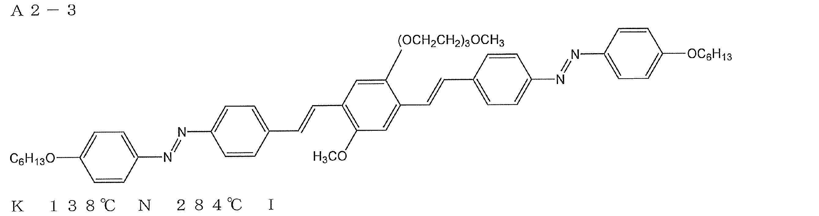


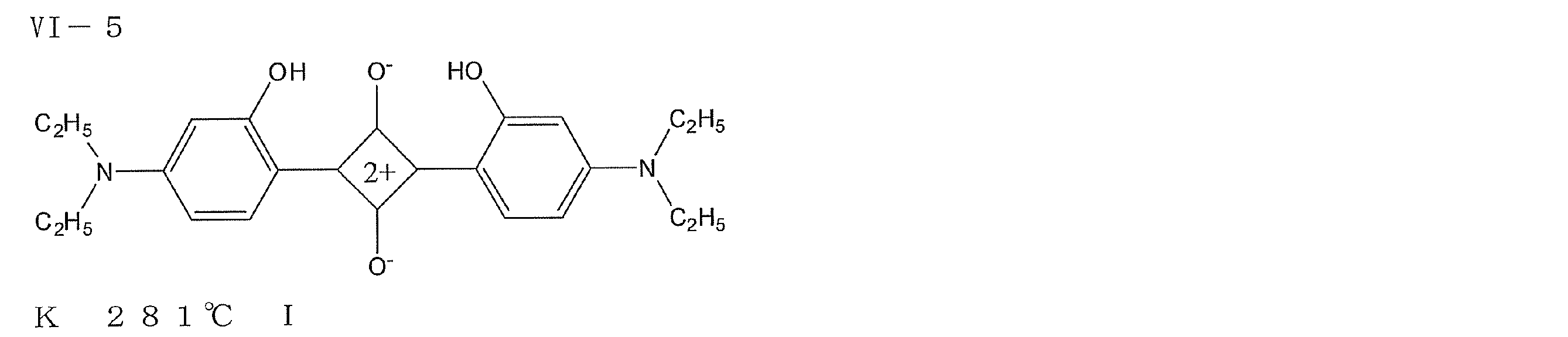
(酸素遮断層用塗布液の調製)
下記組成物をミキシングタンクに投入し、攪拌して酸素遮断層用塗布液とした。
ポリビニルアルコール(PVA205(商品名、クラレ(株)製)3.2質量部、ポリビニルピロリドン(PVP K-30(商品名、日本触媒(株)製)1.5質量部、メタノール44質量部、水56質量部を添加して攪拌した。孔径0.4μmのポリプロピレン製フィルタで濾過して酸素遮断層用塗布液を調製した。
下記組成物をミキシングタンクに投入し、攪拌して酸素遮断層用塗布液とした。
ポリビニルアルコール(PVA205(商品名、クラレ(株)製)3.2質量部、ポリビニルピロリドン(PVP K-30(商品名、日本触媒(株)製)1.5質量部、メタノール44質量部、水56質量部を添加して攪拌した。孔径0.4μmのポリプロピレン製フィルタで濾過して酸素遮断層用塗布液を調製した。
(酸素遮断層の作製)
前記記載の、直線偏光層の上層に、前記酸素遮断層用塗布液を塗布し、100℃で2分間乾燥し酸素遮断層を作製した。酸素遮断層の厚さは1μmであり、正面Reは0nmであった。
前記記載の、直線偏光層の上層に、前記酸素遮断層用塗布液を塗布し、100℃で2分間乾燥し酸素遮断層を作製した。酸素遮断層の厚さは1μmであり、正面Reは0nmであった。
(透明樹脂硬化層用塗布液の調製)
下記組成物をミキシングタンクに投入し、攪拌して透明樹脂硬化層塗布液とした。
トリメチロールプロパントリアクリレート(ビスコート#295(商品名、大阪有機化学(株)製)7.5質量部に、質量平均分子量15000のポリ(グリシジルメタクリレート)2.7質量部、メチルエチルケトン7.3質量部、シクロヘキサノン5.0質量部及び光重合開始剤(イルガキュア184(商品名)、チバ・スペシャルティ・ケミカルズ(株)製)0.5質量部を添加して攪拌した。孔径0.4μmのポリプロピレン製フィルタで濾過して透明樹脂硬化層用の塗布液を調製した。
下記組成物をミキシングタンクに投入し、攪拌して透明樹脂硬化層塗布液とした。
トリメチロールプロパントリアクリレート(ビスコート#295(商品名、大阪有機化学(株)製)7.5質量部に、質量平均分子量15000のポリ(グリシジルメタクリレート)2.7質量部、メチルエチルケトン7.3質量部、シクロヘキサノン5.0質量部及び光重合開始剤(イルガキュア184(商品名)、チバ・スペシャルティ・ケミカルズ(株)製)0.5質量部を添加して攪拌した。孔径0.4μmのポリプロピレン製フィルタで濾過して透明樹脂硬化層用の塗布液を調製した。
(透明樹脂硬化層用塗布液の作製)
前記酸素遮断層の上層に、該透明樹脂硬化層用塗布液を塗布し、100℃で2分間乾燥した。その後、窒素雰囲気下(酸素濃度100ppm以下)5Jの紫外線を照射して重合し、直線偏光層(層厚0.4μm)の表面に、層厚1μmの酸素遮断層、層厚2μmの透明樹脂硬化層が順次積層された積層体を作製した。透明樹脂硬化層の正面Reは0nmであった。
前記酸素遮断層の上層に、該透明樹脂硬化層用塗布液を塗布し、100℃で2分間乾燥した。その後、窒素雰囲気下(酸素濃度100ppm以下)5Jの紫外線を照射して重合し、直線偏光層(層厚0.4μm)の表面に、層厚1μmの酸素遮断層、層厚2μmの透明樹脂硬化層が順次積層された積層体を作製した。透明樹脂硬化層の正面Reは0nmであった。
(パターニングされた位相差層の作製)
前記透明樹脂硬化層の上層に、実施例2-1と同様の方法でパターニングされた位相差層を含む積層体を積層した。
前記透明樹脂硬化層の上層に、実施例2-1と同様の方法でパターニングされた位相差層を含む積層体を積層した。
(画像受像層の作製)
直線偏光層と反対側の保護層の表面に、実施例2-2と同様の方法で画像受像層を形成した
直線偏光層と反対側の保護層の表面に、実施例2-2と同様の方法で画像受像層を形成した
(立体画像用印画紙の作製)
この様にして、図16に示す構成と同様(但し、保護層14aと直線偏光層との間に配向膜が配置され、また保護層14bが、酸素遮断層及び透明樹脂硬化層の積層体である)の構成の立体画像用印画紙を製造した。塗布型直線偏光層24の一方の表面に、配向膜付きセルロースアセテート保護フィルム(14a)、及び他方の表面に酸素遮断層と透明硬化樹脂層の積層体(14b)が配置されており、さらに、観察者の視認側には、パターニング位相差層26及びその形成に利用された配向層25及び開始剤層30を有し、且つ反対側には、無機微粒子と水溶性高分子を含有する組成物からなる画像受像層22が配置されている、立体画像用印画紙を製造した。
この様にして、図16に示す構成と同様(但し、保護層14aと直線偏光層との間に配向膜が配置され、また保護層14bが、酸素遮断層及び透明樹脂硬化層の積層体である)の構成の立体画像用印画紙を製造した。塗布型直線偏光層24の一方の表面に、配向膜付きセルロースアセテート保護フィルム(14a)、及び他方の表面に酸素遮断層と透明硬化樹脂層の積層体(14b)が配置されており、さらに、観察者の視認側には、パターニング位相差層26及びその形成に利用された配向層25及び開始剤層30を有し、且つ反対側には、無機微粒子と水溶性高分子を含有する組成物からなる画像受像層22が配置されている、立体画像用印画紙を製造した。
[立体画像印刷物の作製]
実施例2-2と同様の方法で右眼用画素及び左眼用画素を作製した。
画像を形成した後、画像受像層の上層に、アルミ反射層を積層し、図17に示すのと同様の立体画像印刷物を製造した。
実施例2-2と同様の方法で右眼用画素及び左眼用画素を作製した。
画像を形成した後、画像受像層の上層に、アルミ反射層を積層し、図17に示すのと同様の立体画像印刷物を製造した。
[立体画像の観察]
観察者が直線偏光メガネを介して前記立体画像印刷物を観察したところ、クロストークやゴースト像のない鮮明な立体画像を観察することができた。
観察者が直線偏光メガネを介して前記立体画像印刷物を観察したところ、クロストークやゴースト像のない鮮明な立体画像を観察することができた。
16.実施例2-4
[立体画像用印画物の作製]
保護層作製時の添加剤溶液Bから添加剤B1(Re低下剤)、及び添加剤B2(波長分散制御剤)を除いた以外は、実施例2-1と同様に立体画像用印刷物を作製した。このときの保護層(セルロースアセテート保護フィルム)の厚みは200μmであり、550nmにおけるRe値は15nm、Rthは85nmであった。
[立体画像の観察]
観察者が偏光メガネを介して前記立体画像印刷物を観察したところ立体画像は観察可能であったが、該保護層の高いReにより、若干のゴースト像が認識されてしまった。
[立体画像用印画物の作製]
保護層作製時の添加剤溶液Bから添加剤B1(Re低下剤)、及び添加剤B2(波長分散制御剤)を除いた以外は、実施例2-1と同様に立体画像用印刷物を作製した。このときの保護層(セルロースアセテート保護フィルム)の厚みは200μmであり、550nmにおけるRe値は15nm、Rthは85nmであった。
[立体画像の観察]
観察者が偏光メガネを介して前記立体画像印刷物を観察したところ立体画像は観察可能であったが、該保護層の高いReにより、若干のゴースト像が認識されてしまった。
17.実施例2-5
[立体画像用印画物の作製]
アルミ反射層を積層しない以外は、実施例2-3と同様に立体画像用印刷物を作製した。
[立体画像の観察]
観察者が直線偏光メガネを介して前記立体画像印刷物を観察したところ、クロストークやゴースト像のない鮮明な立体画像を観察することができた。
また、観察者が直線偏光メガネを介して前記立体画像印刷物をパターニングされた位相差層の0°の方向(図4に示す偏光軸cの方向)に30度傾けて観察したところ、若干のクロストークが認識されるものの、立体画像を観察することができた。
一方、実施例2-1の立体画像印刷物を同様に傾けて観察したところ、大きなクロストークを生じ、立体画像として認識することはできなかった。
前記立体画像印刷物は、塗布型偏光膜が薄膜であっても偏光機能を発現できるため、パターニングされた位相差層と画像受像層の間が約60μmと短くなっているのに対し、実施例2-1の立体画像印刷物は、偏光膜が延伸型のヨウ素偏光膜であるため、塗布型偏光膜に比べて厚膜であり、そのため、パターニングされた位相差層と画像受像層の間が約140μm離れており、傾けた際により大きな視差を生じる。そのため、大きなクロストークが発生したと考えられる。
[立体画像用印画物の作製]
アルミ反射層を積層しない以外は、実施例2-3と同様に立体画像用印刷物を作製した。
[立体画像の観察]
観察者が直線偏光メガネを介して前記立体画像印刷物を観察したところ、クロストークやゴースト像のない鮮明な立体画像を観察することができた。
また、観察者が直線偏光メガネを介して前記立体画像印刷物をパターニングされた位相差層の0°の方向(図4に示す偏光軸cの方向)に30度傾けて観察したところ、若干のクロストークが認識されるものの、立体画像を観察することができた。
一方、実施例2-1の立体画像印刷物を同様に傾けて観察したところ、大きなクロストークを生じ、立体画像として認識することはできなかった。
前記立体画像印刷物は、塗布型偏光膜が薄膜であっても偏光機能を発現できるため、パターニングされた位相差層と画像受像層の間が約60μmと短くなっているのに対し、実施例2-1の立体画像印刷物は、偏光膜が延伸型のヨウ素偏光膜であるため、塗布型偏光膜に比べて厚膜であり、そのため、パターニングされた位相差層と画像受像層の間が約140μm離れており、傾けた際により大きな視差を生じる。そのため、大きなクロストークが発生したと考えられる。
18.実施例2-6
[立体画像用印画物の作製]
直線偏光層作製時の直線偏光層用組成物を、下記組成に変更した以外は、実施例2-3と同様に立体画像用印刷物を作製した。このときの直線偏光層の厚みは0.4μmであり、二色比は37であった。
[立体画像用印画物の作製]
直線偏光層作製時の直線偏光層用組成物を、下記組成に変更した以外は、実施例2-3と同様に立体画像用印刷物を作製した。このときの直線偏光層の厚みは0.4μmであり、二色比は37であった。
<直線偏光層用組成物>
(1)イエローアゾ色素A2-3 0.2質量部
(2)マゼンタアゾ色素C-9 0.4質量部
(3)シアンアゾ色素A3-1 0.4質量部
(4)クロロホルム 99質量部
(1)イエローアゾ色素A2-3 0.2質量部
(2)マゼンタアゾ色素C-9 0.4質量部
(3)シアンアゾ色素A3-1 0.4質量部
(4)クロロホルム 99質量部

[立体画像の観察]
観察者が直線偏光メガネを介して前記立体画像印刷物を観察したところ、クロストークやゴースト像のない鮮明な立体画像を観察することができた。
観察者が直線偏光メガネを介して前記立体画像印刷物を観察したところ、クロストークやゴースト像のない鮮明な立体画像を観察することができた。
19.実施例2-7
[立体画像用印画物の作製]
直線偏光層作製時の直線偏光層用組成物を、下記組成に変更した以外は、実施例2-3と同様に立体画像用印刷物を作製した。このときの直線偏光層の厚みは0.4μmであり、二色比は30であった。
[立体画像用印画物の作製]
直線偏光層作製時の直線偏光層用組成物を、下記組成に変更した以外は、実施例2-3と同様に立体画像用印刷物を作製した。このときの直線偏光層の厚みは0.4μmであり、二色比は30であった。
<直線偏光層用組成物>
(1)イエローアゾ色素A2-3 0.15質量部
(2)マゼンタアゾ色素C-9 0.30質量部
(3)シアンアゾ色素A3-1 0.15質量部
(4)シアンアゾ色素A4-120 0.40質量部
(4)クロロホルム 99質量部
(1)イエローアゾ色素A2-3 0.15質量部
(2)マゼンタアゾ色素C-9 0.30質量部
(3)シアンアゾ色素A3-1 0.15質量部
(4)シアンアゾ色素A4-120 0.40質量部
(4)クロロホルム 99質量部
[立体画像の観察]
観察者が直線偏光メガネを介して前記立体画像印刷物を観察したところ、クロストークやゴースト像のない鮮明な立体画像を観察することができた。
観察者が直線偏光メガネを介して前記立体画像印刷物を観察したところ、クロストークやゴースト像のない鮮明な立体画像を観察することができた。
20.実施例2-8
[立体画像用印画物の作製]
直線偏光層作製時の直線偏光層用組成物を、下記組成に変更した以外は、実施例2-3と同様に立体画像用印刷物を作製した。このときの直線偏光層の厚みは0.8μmであり、二色比は71であった。
[立体画像用印画物の作製]
直線偏光層作製時の直線偏光層用組成物を、下記組成に変更した以外は、実施例2-3と同様に立体画像用印刷物を作製した。このときの直線偏光層の厚みは0.8μmであり、二色比は71であった。
<直線偏光層用組成物>
(1)マゼンタアゾ色素A-16 1.2質量部
(2)マゼンタアゾ色素B-4 0.8質量部
(3)クロロホルム 98質量部
(1)マゼンタアゾ色素A-16 1.2質量部
(2)マゼンタアゾ色素B-4 0.8質量部
(3)クロロホルム 98質量部


[立体画像の観察]
観察者が直線偏光メガネを介して前記立体画像印刷物を観察したところ、クロストークやゴースト像のない鮮明な立体画像を観察することができた。
観察者が直線偏光メガネを介して前記立体画像印刷物を観察したところ、クロストークやゴースト像のない鮮明な立体画像を観察することができた。
21.実施例2-9
実施例2-1で作製したパターニングされた位相差層の表面に、クラレ社製ポリビニルアルコール「PVA103」の4%水溶液を、12番バーで塗布を行い、80℃で5分間乾燥させた。その後に、位相差層の第2のドメインの遅相軸bと45°の角度をなすように400rpmで3往復ラビング処理を行い、ラビング配向膜付パターニングされた位相差層を作製した。
実施例2-1で作製したパターニングされた位相差層の表面に、クラレ社製ポリビニルアルコール「PVA103」の4%水溶液を、12番バーで塗布を行い、80℃で5分間乾燥させた。その後に、位相差層の第2のドメインの遅相軸bと45°の角度をなすように400rpmで3往復ラビング処理を行い、ラビング配向膜付パターニングされた位相差層を作製した。
次に、実施例2-3で調製した直線偏光層用塗布液を前記ラビング配向膜上に塗布し、室温で自然乾燥して直線偏光層を作製した。得られた直線偏光層の厚さは0.4μmであり、二色比は42であった。また、位相差層の第2のドメインの遅相軸bは、直線偏光層の偏光軸cと45°の角度をなしていた。
次に、実施例2-3と同様の手順にて、酸素遮断層及び透明樹脂硬化層を順次積層した。酸素遮断層及び透明樹脂硬化層の層厚は、それぞれ、1μm及び2μmであった。また、各々の層の正面Reは、いずれも0nmであった。
前記透明樹脂硬化層の表面に、実施例2-3と同様の方法で画像受像層を形成した後、実施例2-3と同様の方法で立体画像印刷物を作製した。なお、アルミ反射層は積層しなかった。
[立体画像の観察]
観察者が直線偏光メガネを介して前記立体画像印刷物を観察したところ、クロストークやゴースト像のない鮮明な立体画像を観察することができた。
また、観察者が直線偏光メガネを介して前記立体画像印刷物をパターニングされた位相差層の0°の方向(図4に示す偏光軸cの方向)に30度傾けて観察しても、ほとんどクロストークが認識されず、鮮明な立体画像を観察することができた。
前記立体画像印刷物は、塗布型偏光膜が薄膜で偏光機能を発現でき、パターニングされた位相差層と画像受像層の間が5μm以下と極めて短くなっているため、クロストークが発生しないと考えられる。
観察者が直線偏光メガネを介して前記立体画像印刷物を観察したところ、クロストークやゴースト像のない鮮明な立体画像を観察することができた。
また、観察者が直線偏光メガネを介して前記立体画像印刷物をパターニングされた位相差層の0°の方向(図4に示す偏光軸cの方向)に30度傾けて観察しても、ほとんどクロストークが認識されず、鮮明な立体画像を観察することができた。
前記立体画像印刷物は、塗布型偏光膜が薄膜で偏光機能を発現でき、パターニングされた位相差層と画像受像層の間が5μm以下と極めて短くなっているため、クロストークが発生しないと考えられる。
22.実施例2-10
[立体画像用画像受像フィルムの作製]
(画像受像層の作製)
下記組成中の(1)沈降法シリカ微粒子と(2)イオン交換水と(3)「シャロールDC-902P」と(4)「ZA-30」とを混合し、超音波分散機〔(株)エスエムテー製〕を用いて分散させた後、得られた分散液を45℃に加熱して20時間保持した。その後これに、(5)ホウ酸と(6)ポリビニルアルコール溶解液と(7)スーパーフレックス650と(8)エタノールとを30℃下で加え、画像受像層用塗布液Aを調製した。
[立体画像用画像受像フィルムの作製]
(画像受像層の作製)
下記組成中の(1)沈降法シリカ微粒子と(2)イオン交換水と(3)「シャロールDC-902P」と(4)「ZA-30」とを混合し、超音波分散機〔(株)エスエムテー製〕を用いて分散させた後、得られた分散液を45℃に加熱して20時間保持した。その後これに、(5)ホウ酸と(6)ポリビニルアルコール溶解液と(7)スーパーフレックス650と(8)エタノールとを30℃下で加え、画像受像層用塗布液Aを調製した。
<画像受像層用塗布液Aの組成>
(1)沈降法シリカ微粒子(無機微粒子) 10.0部
(P-78A(粒径7.7μm)とP-604(粒径0.64μm)とを75:25[質量比]にて混合;いずれも水澤化学工業(株)製;以下、シリカ微粒子という。)
(2)イオン交換水 62.8部
(3)シャロールDC-902P(51.5%水溶液) 0.87部
(分散剤、第一工業製薬(株)製)
(4)ZA-30(酢酸ジルコニル) 0.54部
(第一稀元素化学工業(株)製)
(5)ホウ酸(架橋剤) 0.44部
(6)ポリビニルアルコール(水溶性樹脂)溶解液 34.9部
-組成-
・PVA-235 2.43部
(鹸化度88%、重合度3500(株)クラレ製)
・ポリオキシエチレンラウリルエーテル 0.08部
(エマルゲン109P(10%水溶液)、HLB値13.6、花王(株)製;界面活性剤)
・ジエチレングリコールモノブチルエーテル 0.74部
(ブチセノール20P、協和発酵(株)製)
・イオン交換水 31.0部
(7)スーパーフレックス650(25%水分散液) 2.47部
(第一工業製薬(株)製)
(8)エタノール 1.3部
(1)沈降法シリカ微粒子(無機微粒子) 10.0部
(P-78A(粒径7.7μm)とP-604(粒径0.64μm)とを75:25[質量比]にて混合;いずれも水澤化学工業(株)製;以下、シリカ微粒子という。)
(2)イオン交換水 62.8部
(3)シャロールDC-902P(51.5%水溶液) 0.87部
(分散剤、第一工業製薬(株)製)
(4)ZA-30(酢酸ジルコニル) 0.54部
(第一稀元素化学工業(株)製)
(5)ホウ酸(架橋剤) 0.44部
(6)ポリビニルアルコール(水溶性樹脂)溶解液 34.9部
-組成-
・PVA-235 2.43部
(鹸化度88%、重合度3500(株)クラレ製)
・ポリオキシエチレンラウリルエーテル 0.08部
(エマルゲン109P(10%水溶液)、HLB値13.6、花王(株)製;界面活性剤)
・ジエチレングリコールモノブチルエーテル 0.74部
(ブチセノール20P、協和発酵(株)製)
・イオン交換水 31.0部
(7)スーパーフレックス650(25%水分散液) 2.47部
(第一工業製薬(株)製)
(8)エタノール 1.3部
表面がゼラチンで下塗りされた、厚み175μmの二軸延伸ポリエチレンテレフタレートフィルムの下塗り面に、上記より得た画像受像層用塗布液Aを塗布量が204ml/m2となるように塗布した。このとき、8質量%のポリ塩化アルミ水溶液(アルファイン83;大明化学工業(株)製)を画像受像層用塗布液Aに予め、塗布量が12.0ml/m2となるように塗布直前に混合しておいた。
塗布後、熱風乾燥機にて80℃(風速3~8m/秒)にて塗布膜の固形分濃度が20%になるまで乾燥させた。この間、塗布膜は恒率乾燥を示した。そして、この塗布膜を、減率乾燥を示す前に下記組成の塩基性溶液Cに3秒浸漬し、塗布膜上にその13g/m2を付着させ、更に80℃下で10分間乾燥させた。
以上のようにして、乾燥層厚33μmの立体画像用画像受像フィルムを作製した。
<塩基性溶液Cの組成>
(1)ホウ酸 0.65部
(2)炭酸ジルコニルアンモニウム 2.5部
(ジルコゾールAC-7(28%水溶液)、第一稀元素化学工業(株)製)
(3)炭酸アンモニウム(一級;関東化学(株)製) 3.5部
(4)イオン交換水 63.3部
(5)ポリオキシエチレンラウリルエーテル(界面活性剤) 30.0部
(花王(株)製、エマルゲン109P(2%水溶液)、HLB値13.6)
以上のようにして、乾燥層厚33μmの立体画像用画像受像フィルムを作製した。
<塩基性溶液Cの組成>
(1)ホウ酸 0.65部
(2)炭酸ジルコニルアンモニウム 2.5部
(ジルコゾールAC-7(28%水溶液)、第一稀元素化学工業(株)製)
(3)炭酸アンモニウム(一級;関東化学(株)製) 3.5部
(4)イオン交換水 63.3部
(5)ポリオキシエチレンラウリルエーテル(界面活性剤) 30.0部
(花王(株)製、エマルゲン109P(2%水溶液)、HLB値13.6)
[立体画像用画像受像フィルムへの印字]
左右二系統の撮影レンズを備えたデジタルカメラで撮影した、右眼用データ及び左眼用データを、各々、デジタルデータに変換したのち、インクジェット用インクをピエゾ方式のインクジェットヘッドを用いて、上記立体画像用画像受像フィルムの画像受像層に打滴し、右眼用画素及び左眼用画素を作製した。右眼用画素及び左眼用画素は、254μmごとに交互に入れ替えた横ストライプ形状として画像を出力した。
左右二系統の撮影レンズを備えたデジタルカメラで撮影した、右眼用データ及び左眼用データを、各々、デジタルデータに変換したのち、インクジェット用インクをピエゾ方式のインクジェットヘッドを用いて、上記立体画像用画像受像フィルムの画像受像層に打滴し、右眼用画素及び左眼用画素を作製した。右眼用画素及び左眼用画素は、254μmごとに交互に入れ替えた横ストライプ形状として画像を出力した。
[立体画像用印刷物の作製]
<1/2波長層の作製>
実施例2-1で作製したセルロースアセテート保護フィルム表面に、クラレ社製ポリビニルアルコール「PVA103」の4%水溶液を、12番バーで塗布を行い、80℃で5分間乾燥させた。その後に、400rpmで一方向に1往復、ラビング処理を行い、ラビング配向層付透明支持体を作製した。なお、配向層の厚みは0.9μmであった。
<1/2波長層の作製>
実施例2-1で作製したセルロースアセテート保護フィルム表面に、クラレ社製ポリビニルアルコール「PVA103」の4%水溶液を、12番バーで塗布を行い、80℃で5分間乾燥させた。その後に、400rpmで一方向に1往復、ラビング処理を行い、ラビング配向層付透明支持体を作製した。なお、配向層の厚みは0.9μmであった。
下記組成の位相差層形成用組成物を調製後、孔径0.2μmのポリプロピレン製フィルタでろ過して、1/2波長用塗布液として用いる。該塗布液を塗布、膜面温度80℃で1分間乾燥して液晶相状態とし均一配向させた後、室温まで冷却した。次に、横ストライプ幅254μmのマスクを1/2波長層用塗布液を塗布した基板上に配置し、空気下にて20mW/cm2の空冷メタルハライドランプ(アイグラフィックス(株)製)を用いて紫外線を5秒間照射して、その配向状態を固定化することにより第1位相差領域を形成した。続いて、膜面温度140℃まで昇温し、一旦等方相にした後、20mW/cm2で20秒間全面照射して、その配向状態を固定化することにより第2位相差領域を形成した。この様にしてパターニング1/2波長層を作製した。膜厚は、1.6μmであり、チルト角は、ほぼ90°であり、測定波長550nmにおける第1位相差領域のReは275nmであり、保護層とのRthの合計は-80nmであり、第2位相差領域のReは0nmであり、Rthは0nmであった。
<位相差層形成用組成物>
ディスコティック液晶E-1 100質量部
配向膜界面配向剤(II-1) 1.0質量部
空気界面配向剤(P-1) 0.4質量部
光重合開始剤 3.0質量部
(イルガキュア907、チバ・スペシャルティ・ケミカルズ(株)製)
増感剤(カヤキュア-DETX、日本化薬(株)製) 1.0質量部
メチルエチルケトン 300質量部
ディスコティック液晶E-1 100質量部
配向膜界面配向剤(II-1) 1.0質量部
空気界面配向剤(P-1) 0.4質量部
光重合開始剤 3.0質量部
(イルガキュア907、チバ・スペシャルティ・ケミカルズ(株)製)
増感剤(カヤキュア-DETX、日本化薬(株)製) 1.0質量部
メチルエチルケトン 300質量部
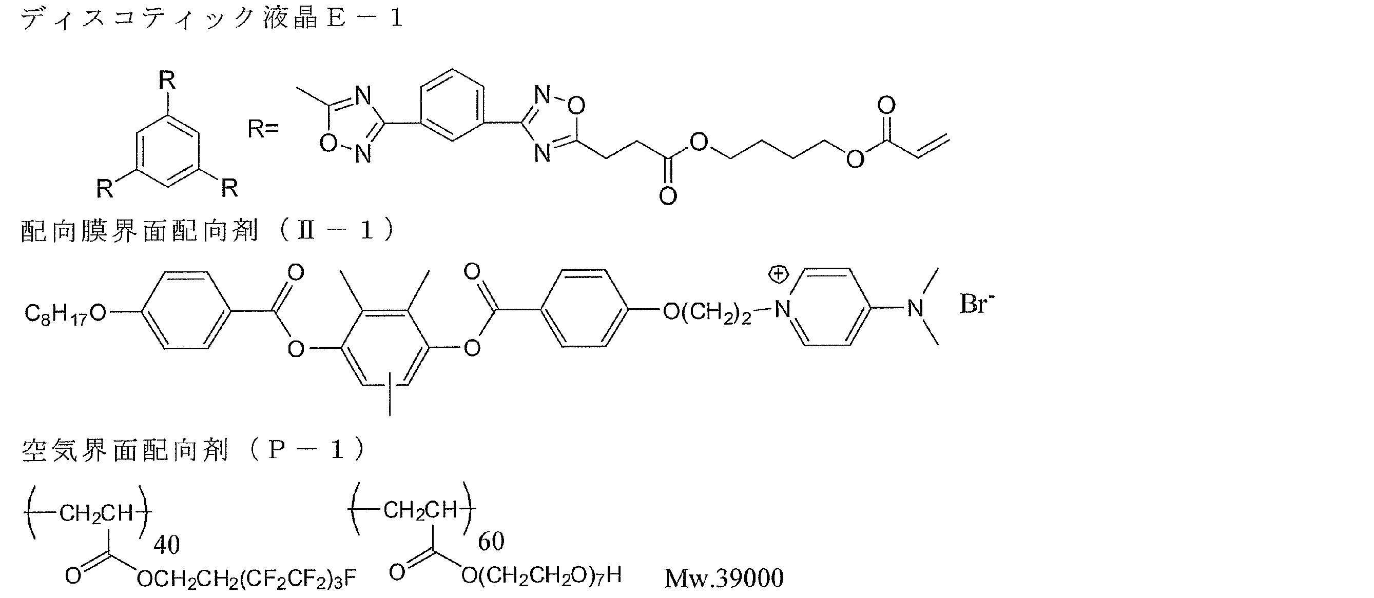
<直線偏光層の作製>
厚さ80μmのポリビニルアルコールフィルムをヨウ素水溶液中で5倍に延伸し、乾燥して厚さ30μmの直線偏光層を得た。
厚さ80μmのポリビニルアルコールフィルムをヨウ素水溶液中で5倍に延伸し、乾燥して厚さ30μmの直線偏光層を得た。
<パターニング1/2波長層と直線偏光層との積層>
上記のパターニング1/2波長層の1/2波長層側に偏光層がくるように粘着剤で貼り付け、更に偏光層のもう一方の側に実施例2-1で作製したセルロースアセテート保護フィルムをアルカリケン化処理を行った後、粘着剤を塗設してから貼り合わせ、パターニング1/2波長層と偏光層を積層した。なお、直線偏光層の偏光軸が、パターニング1/2波長層の遅相軸と、45°となるように貼合せを行い、粘着剤層の厚みは16μmであった。
上記のパターニング1/2波長層の1/2波長層側に偏光層がくるように粘着剤で貼り付け、更に偏光層のもう一方の側に実施例2-1で作製したセルロースアセテート保護フィルムをアルカリケン化処理を行った後、粘着剤を塗設してから貼り合わせ、パターニング1/2波長層と偏光層を積層した。なお、直線偏光層の偏光軸が、パターニング1/2波長層の遅相軸と、45°となるように貼合せを行い、粘着剤層の厚みは16μmであった。
<直線偏光層と立体画像用画像受像フィルムとの積層>
上記で作製したパターニング1/2波長層付直線偏光層を、粘着剤を用いて立体画像用画像受像フィルムと貼り合わせた。なお貼合は、パターニング1/2波長層のストライプと立体画像用画像受像フィルムに印字したストライプが一致するように貼合せを行い、粘着剤層の厚みは16μmであった。
この様にして、図8に示す構成と同様の立体画像印刷物を得た。
上記で作製したパターニング1/2波長層付直線偏光層を、粘着剤を用いて立体画像用画像受像フィルムと貼り合わせた。なお貼合は、パターニング1/2波長層のストライプと立体画像用画像受像フィルムに印字したストライプが一致するように貼合せを行い、粘着剤層の厚みは16μmであった。
この様にして、図8に示す構成と同様の立体画像印刷物を得た。
[立体画像の観察]
観察者が円偏光メガネを介して前記立体画像印刷物を観察したところ、クロストークやゴースト像のない鮮明な立体画像を観察することができた。
また、観察者が円偏光メガネを介して前記立体画像印刷物をパターニングされた位相差層の0°の方向(図4に示す偏光軸cの方向)に30度傾けて観察しても、ほとんどクロストークが認識されず、鮮明な立体画像を観察することができた。
前記立体画像印刷物は、パターニング1/2波長層と画像受像層の距離dは122μmであり、パターン幅pは254μmであり、d/pは0.48であるためクロストークが発生しないと考えられる。
観察者が円偏光メガネを介して前記立体画像印刷物を観察したところ、クロストークやゴースト像のない鮮明な立体画像を観察することができた。
また、観察者が円偏光メガネを介して前記立体画像印刷物をパターニングされた位相差層の0°の方向(図4に示す偏光軸cの方向)に30度傾けて観察しても、ほとんどクロストークが認識されず、鮮明な立体画像を観察することができた。
前記立体画像印刷物は、パターニング1/2波長層と画像受像層の距離dは122μmであり、パターン幅pは254μmであり、d/pは0.48であるためクロストークが発生しないと考えられる。
23.実施例2-11
[立体画像用印画紙の作製]
実施例2-10と同様の方法にて、立体画像用画像受像フィルムを作製した後、同様に印字を行った。
[立体画像用印画紙の作製]
実施例2-10と同様の方法にて、立体画像用画像受像フィルムを作製した後、同様に印字を行った。
[立体画像用印刷物の作製]
<1/2波長層の作製>
実施例2-10で作製したラビング配向層付透明支持体に、実施例2-10で作製した1/2波長用塗布液を塗布、膜面温度80℃で1分間乾燥して液晶相状態とし均一配向させた後、室温まで冷却した。次に、横ストライプ幅254μmのマスクを1/2波長層用塗布液を塗布した基板上に配置し、空気下にて20mW/cm2の空冷メタルハライドランプ(アイグラフィックス(株)製)を用いて紫外線を5秒間照射して、その配向状態を固定化することにより第1位相差領域を形成した。続いて、エタノール溶液で未照射を洗浄除去することによりパターニング1/2波長層を作製した。膜厚は、1.6μmであり、チルト角は、ほぼ90°であり、測定波長550nmにおける第1位相差領域のReは275nmであり、保護層とのRthの合計は-80nmであり、洗浄領域(第2位相差領域)のReは0nmであり、Rthは0nmであった。
<1/2波長層の作製>
実施例2-10で作製したラビング配向層付透明支持体に、実施例2-10で作製した1/2波長用塗布液を塗布、膜面温度80℃で1分間乾燥して液晶相状態とし均一配向させた後、室温まで冷却した。次に、横ストライプ幅254μmのマスクを1/2波長層用塗布液を塗布した基板上に配置し、空気下にて20mW/cm2の空冷メタルハライドランプ(アイグラフィックス(株)製)を用いて紫外線を5秒間照射して、その配向状態を固定化することにより第1位相差領域を形成した。続いて、エタノール溶液で未照射を洗浄除去することによりパターニング1/2波長層を作製した。膜厚は、1.6μmであり、チルト角は、ほぼ90°であり、測定波長550nmにおける第1位相差領域のReは275nmであり、保護層とのRthの合計は-80nmであり、洗浄領域(第2位相差領域)のReは0nmであり、Rthは0nmであった。
<直線偏光層の作製>
厚さ80μmのポリビニルアルコールフィルムをヨウ素水溶液中で5倍に延伸し、乾燥して厚さ30μmの直線偏光層を得た。
厚さ80μmのポリビニルアルコールフィルムをヨウ素水溶液中で5倍に延伸し、乾燥して厚さ30μmの直線偏光層を得た。
<パターニング1/2波長層と直線偏光層との積層>
上記のパターニング1/2波長層の1/2波長層側に偏光層がくるように粘着剤で貼り付けパターニング1/2波長層と偏光層を積層した。なお、直線偏光層の偏光軸が、パターニング1/2波長層の遅相軸と45°となるように貼合せを行い、粘着剤層の厚みは16μmであった。
上記のパターニング1/2波長層の1/2波長層側に偏光層がくるように粘着剤で貼り付けパターニング1/2波長層と偏光層を積層した。なお、直線偏光層の偏光軸が、パターニング1/2波長層の遅相軸と45°となるように貼合せを行い、粘着剤層の厚みは16μmであった。
<直線偏光層と立体画像用画像受像フィルムとの積層>
上記で作製したパターニング1/2波長層付直線偏光層を、粘着剤を用いて立体画像用画像受像フィルムと貼り合わせた。なお貼合は、パターニング1/2波長層のストライプと立体画像用画像受像フィルムに印字したストライプが一致するように貼合せを行い、粘着剤層の厚みは16μmであった。
この様にして、図9に示す構成と同様の立体画像印刷物を得た。
上記で作製したパターニング1/2波長層付直線偏光層を、粘着剤を用いて立体画像用画像受像フィルムと貼り合わせた。なお貼合は、パターニング1/2波長層のストライプと立体画像用画像受像フィルムに印字したストライプが一致するように貼合せを行い、粘着剤層の厚みは16μmであった。
この様にして、図9に示す構成と同様の立体画像印刷物を得た。
[立体画像の観察]
観察者が円偏光メガネを介して前記立体画像印刷物を観察したところ、クロストークやゴースト像のない鮮明な立体画像を観察することができた。
また、観察者が円偏光メガネを介して前記立体画像印刷物をパターニングされた1/2波長層の0°の方向(図4に示す偏光軸cの方向)に30度傾けて観察しても、ほとんどクロストークが認識されず、鮮明な立体画像を観察することができた。
前記立体画像印刷物は、パターニング1/2波長層と画像受像層の距離dは62μmであり、パターン幅pは254μmであり、d/pは0.24であるためクロストークが発生しないと考えられる。
観察者が円偏光メガネを介して前記立体画像印刷物を観察したところ、クロストークやゴースト像のない鮮明な立体画像を観察することができた。
また、観察者が円偏光メガネを介して前記立体画像印刷物をパターニングされた1/2波長層の0°の方向(図4に示す偏光軸cの方向)に30度傾けて観察しても、ほとんどクロストークが認識されず、鮮明な立体画像を観察することができた。
前記立体画像印刷物は、パターニング1/2波長層と画像受像層の距離dは62μmであり、パターン幅pは254μmであり、d/pは0.24であるためクロストークが発生しないと考えられる。
24.比較例2-1
画像受像層22を形成しなかった以外は、実施例2-2で作製したのと同様の構成の積層体を作製した。
直線偏光層のパターニングされた位相差層と反対側に積層されたセルロースアセテート保護フィルムの表面に、実施例2-1と同様に感熱転写法で、及び実施例2-2と同様にインクジェット法で画像を形成したが、形成された画像濃度は低く、またセルロースアセテートフィルム上で色素が移動してしまい、所望の画像を形成できなかった。その結果、直線偏光メガネを装着して観察しても、立体画像として認識することはできなかった。
画像受像層22を形成しなかった以外は、実施例2-2で作製したのと同様の構成の積層体を作製した。
直線偏光層のパターニングされた位相差層と反対側に積層されたセルロースアセテート保護フィルムの表面に、実施例2-1と同様に感熱転写法で、及び実施例2-2と同様にインクジェット法で画像を形成したが、形成された画像濃度は低く、またセルロースアセテートフィルム上で色素が移動してしまい、所望の画像を形成できなかった。その結果、直線偏光メガネを装着して観察しても、立体画像として認識することはできなかった。
25.実施例3-1
<立体画像用リバーサルフィルムの準備>
リバーサルフィルム(富士フイルム社製フジクローム ベルビア50)を準備した。
左右二系統の撮影レンズを備えたデジタルカメラ(富士フイルム社製FinePix Real 3D W1)を用いて、右眼用画像及び左眼用画像を作成した。次に、3D画像作成用ソフト(ストライパー)を用いて右眼用画像及び左眼用画像を200μmごとに交互に入れ替えた画像を作成した。最後に、上記準備した市販のリバーサルフィルムに、該画像データをライトジェット2080(解像度:1016dpi,リバーサル(RDPIII))により出力し、3次元立体写真用透明画像(有効画面サイズ 178mmx232mm)を得た。
<立体画像用リバーサルフィルムの準備>
リバーサルフィルム(富士フイルム社製フジクローム ベルビア50)を準備した。
左右二系統の撮影レンズを備えたデジタルカメラ(富士フイルム社製FinePix Real 3D W1)を用いて、右眼用画像及び左眼用画像を作成した。次に、3D画像作成用ソフト(ストライパー)を用いて右眼用画像及び左眼用画像を200μmごとに交互に入れ替えた画像を作成した。最後に、上記準備した市販のリバーサルフィルムに、該画像データをライトジェット2080(解像度:1016dpi,リバーサル(RDPIII))により出力し、3次元立体写真用透明画像(有効画面サイズ 178mmx232mm)を得た。
<1/4波長層の作製>
[ラビング配向膜付透明支持体の作製]
市販のセルロールアセテートフィルム(フジタックTD80UF、富士フイルム(株)製、Re(550)は3nm、|Rth(630)|は50nm)の表面に、クラレ社製ポリビニルアルコール「PVA103」の4%水溶液を、12番バーで塗布を行い、80℃で5分間乾燥させた。その後に、400rpmで一方向に3往復、ラビング処理を行い、ラビング配向膜付支持体を作製した。なお、配向膜の膜厚は、0.9μmであった。
[ラビング配向膜付透明支持体の作製]
市販のセルロールアセテートフィルム(フジタックTD80UF、富士フイルム(株)製、Re(550)は3nm、|Rth(630)|は50nm)の表面に、クラレ社製ポリビニルアルコール「PVA103」の4%水溶液を、12番バーで塗布を行い、80℃で5分間乾燥させた。その後に、400rpmで一方向に3往復、ラビング処理を行い、ラビング配向膜付支持体を作製した。なお、配向膜の膜厚は、0.9μmであった。
[パターニング位相差層の作製]
下記組成の位相差層形成用組成物を調製後、孔径0.2μmのポリプロピレン製フィルタでろ過して、光学異方性層用塗布液として用いた。該塗布液を塗布し、膜面温度80℃で1分間乾燥して液晶相状態とし均一配向させた後、室温まで冷却した。次に、200μmピッチのストライプマスクを光学異方性層用塗布液を塗布した基板上に配置し、空気下にて20mW/cm2の空冷メタルハライドランプ(アイグラフィックス(株)製)を用いて紫外線を5秒間照射して、その配向状態を固定化することにより第1位相差領域を形成した。続いて、膜面温度140℃まで昇温し、一旦等方相にした後、100℃まで降温し、その温度で1分間加熱して均一配向させた。室温まで冷却した後、20mW/cm2で20秒間全面照射して、その配向状態を固定化することにより第2位相差領域を形成した。この様にしてパターニング位相差板1を作製した。膜厚は、0.8μmであった。
下記組成の位相差層形成用組成物を調製後、孔径0.2μmのポリプロピレン製フィルタでろ過して、光学異方性層用塗布液として用いた。該塗布液を塗布し、膜面温度80℃で1分間乾燥して液晶相状態とし均一配向させた後、室温まで冷却した。次に、200μmピッチのストライプマスクを光学異方性層用塗布液を塗布した基板上に配置し、空気下にて20mW/cm2の空冷メタルハライドランプ(アイグラフィックス(株)製)を用いて紫外線を5秒間照射して、その配向状態を固定化することにより第1位相差領域を形成した。続いて、膜面温度140℃まで昇温し、一旦等方相にした後、100℃まで降温し、その温度で1分間加熱して均一配向させた。室温まで冷却した後、20mW/cm2で20秒間全面照射して、その配向状態を固定化することにより第2位相差領域を形成した。この様にしてパターニング位相差板1を作製した。膜厚は、0.8μmであった。
<位相差層形成用組成物>
ディスコティック液晶E-1 100質量部
配向膜界面配向剤(II-1) 1.0質量部
空気界面配向剤(P-1) 0.4質量部
光重合開始剤 3.0質量部
(イルガキュア907、チバ・スペシャルティ・ケミカルズ(株)製)
増感剤(カヤキュア-DETX、日本化薬(株)製) 1.0質量部
メチルエチルケトン 300質量部
ディスコティック液晶E-1 100質量部
配向膜界面配向剤(II-1) 1.0質量部
空気界面配向剤(P-1) 0.4質量部
光重合開始剤 3.0質量部
(イルガキュア907、チバ・スペシャルティ・ケミカルズ(株)製)
増感剤(カヤキュア-DETX、日本化薬(株)製) 1.0質量部
メチルエチルケトン 300質量部

パターニング位相差層を、第1位相差領域又は第2位相差領域のいずれか一方の遅相軸が、直交位に組合された2枚の偏光板のいずれか一方の偏光軸と平行になるように、偏光板の間に入れ、さらに、位相差530nmの鋭敏色板を、その遅相軸が偏光板の偏光軸と45°の角度をなすように、位相差層の上においた。次に、位相差層を+45°回転させた状態、及び-45°回転させた状態を偏光顕微鏡(NIKON製 ECLIPE E600W POL)で観察した。+45°回転させた場合は、第1位相差領域の遅相軸と鋭敏色板の遅相軸が平行になっているため、位相差は530nmよりも大きくなり、その色は青色に変化した。一方、第2位相差領域の遅相軸は鋭敏色板の遅相軸と直交しているため、位相差は530nmよりも小さくなり、その色は黄色に変化した。-45°回転させた場合、逆の現象となった。これらの観察結果から、第1位相差領域及び第2位相差領域の面内遅相軸が直交していることを確認した。
[位相差板の評価]
作製したパターニング位相差板1について、KOBRA-21ADH(王子計測器(株)製)を用いて前記方法に従って、配向膜界面のディスコティック液晶のチルト角(分子の円盤面の層面に対する角度)、空気界面のディスコティック液晶のチルト角、及びRe、Rthをそれぞれ測定した。結果を表1に示す。下記表中、垂直とは、チルト角70°~90°を表す。また、パターニング位相差板1について、KOBRA-21ADH(王子計測器(株)製)を用いて、前記方法に従って、第1及び第2位相差領域の面内遅相軸の方向を決定した。表1に、第1及び第2位相差領域の面内遅相軸の方向と配向膜のラビング方向の方向との関係を示す。

作製したパターニング位相差板1について、KOBRA-21ADH(王子計測器(株)製)を用いて前記方法に従って、配向膜界面のディスコティック液晶のチルト角(分子の円盤面の層面に対する角度)、空気界面のディスコティック液晶のチルト角、及びRe、Rthをそれぞれ測定した。結果を表1に示す。下記表中、垂直とは、チルト角70°~90°を表す。また、パターニング位相差板1について、KOBRA-21ADH(王子計測器(株)製)を用いて、前記方法に従って、第1及び第2位相差領域の面内遅相軸の方向を決定した。表1に、第1及び第2位相差領域の面内遅相軸の方向と配向膜のラビング方向の方向との関係を示す。
表1に示す結果から、パターニング位相差板1は、垂直配向状態に固定されたディスコティック液晶を含有し、面内遅相軸が直交した第1位相差領域と第2位相差領域を有する、1/4波長板として機能する位相差板であることが理解できる。
[偏光板の作製]
厚さ80μmのロール状ポリビニルアルコールフィルムをヨウ素水溶液中で連続して5倍に延伸し、乾燥して厚さ30μmの偏光膜を得た。
上記で作製したパターニング位相差板1を粘着剤を用いて45°で偏光板と貼り合わせた。さらに貼合時は、粘着剤を用いて、円偏光メガネをかけながらバックライトに照らして、パターニング位相差板1、直線偏光層及びリバーサル画像を貼合した。粘着剤層の厚さは各々16μmであった。
この様にして、図19に示す構成の立体画像印刷物を得た。
厚さ80μmのロール状ポリビニルアルコールフィルムをヨウ素水溶液中で連続して5倍に延伸し、乾燥して厚さ30μmの偏光膜を得た。
上記で作製したパターニング位相差板1を粘着剤を用いて45°で偏光板と貼り合わせた。さらに貼合時は、粘着剤を用いて、円偏光メガネをかけながらバックライトに照らして、パターニング位相差板1、直線偏光層及びリバーサル画像を貼合した。粘着剤層の厚さは各々16μmであった。
この様にして、図19に示す構成の立体画像印刷物を得た。
(実装評価)
作製した立体画像印刷物を、図19に示す通り、バックライトに照らして、右眼用/左眼用の円偏光メガネを通して観察したところ、クロストークのない鮮明な立体画像を観察することができた。また、特に、奥行き感にも優れていた。
さらに、観察者が円偏光メガネを介して前記立体画像印刷物をパターニングされた1/4波長層の0°の方向(図2に示す偏光軸cの方向)に30度傾けて観察しても、ほとんどクロストークが認識されず、鮮明な立体画像を観察することができた。
前記立体画像印刷物は、パターニング1/4波長層と画像受像層の距離dは62μmであり、パターン幅pは200μmであり、d/pは0.31であるためクロストークが発生しないと考えられる。
作製した立体画像印刷物を、図19に示す通り、バックライトに照らして、右眼用/左眼用の円偏光メガネを通して観察したところ、クロストークのない鮮明な立体画像を観察することができた。また、特に、奥行き感にも優れていた。
さらに、観察者が円偏光メガネを介して前記立体画像印刷物をパターニングされた1/4波長層の0°の方向(図2に示す偏光軸cの方向)に30度傾けて観察しても、ほとんどクロストークが認識されず、鮮明な立体画像を観察することができた。
前記立体画像印刷物は、パターニング1/4波長層と画像受像層の距離dは62μmであり、パターン幅pは200μmであり、d/pは0.31であるためクロストークが発生しないと考えられる。
26.実施例3-2:光配向膜を利用した1/4位相差を利用した実施例
[立体画像用印画紙の作製]
<立体画像用リバーサルフィルムの準備>
リバーサルフィルム(富士フイルム社製フジクローム ベルビア50)を準備し、実施例3-1と同様にして、3D画像を形成した。
[立体画像用印画紙の作製]
<立体画像用リバーサルフィルムの準備>
リバーサルフィルム(富士フイルム社製フジクローム ベルビア50)を準備し、実施例3-1と同様にして、3D画像を形成した。
(1/4波長層の作製)
<光配向膜の作製>
直線偏光層の保護フィルム(厚さ40μm、正面Re=1nm)の表面に、下記構造の光配向材料E-1 1%水溶液をスピンコート塗布し、100℃で1分間乾燥した。得られた塗布膜に、空気下にて160W/cm2の空冷メタルハライドランプ(アイグラフィックス(株)製)を用いて紫外線を照射する。このとき、ワイヤーグリッド偏光子(Moxtek社製, ProFlux PPL02)を図13(a)に示すように、方向1にセットして、さらにマスクA(画像パターンを有す石英露光マスク)を通して、露光を行う。その後、図13(b)に示すように、ワイヤーグリッド偏光子を方向2にセットして、さらにマスクBを通して、露光を行う。露光マスク面と光配向膜の間の距離を200μmに設定する。この際用いる紫外線の照度はUV-A領域(波長380nm~320nmの積算)において100mW/cm2、照射量はUV-A領域において1000mJ/cm2とする。
<光配向膜の作製>
直線偏光層の保護フィルム(厚さ40μm、正面Re=1nm)の表面に、下記構造の光配向材料E-1 1%水溶液をスピンコート塗布し、100℃で1分間乾燥した。得られた塗布膜に、空気下にて160W/cm2の空冷メタルハライドランプ(アイグラフィックス(株)製)を用いて紫外線を照射する。このとき、ワイヤーグリッド偏光子(Moxtek社製, ProFlux PPL02)を図13(a)に示すように、方向1にセットして、さらにマスクA(画像パターンを有す石英露光マスク)を通して、露光を行う。その後、図13(b)に示すように、ワイヤーグリッド偏光子を方向2にセットして、さらにマスクBを通して、露光を行う。露光マスク面と光配向膜の間の距離を200μmに設定する。この際用いる紫外線の照度はUV-A領域(波長380nm~320nmの積算)において100mW/cm2、照射量はUV-A領域において1000mJ/cm2とする。

<1/4波長層の作製>
下記の1/4波長層用組成物を調製後、孔径0.2μmのポリプロピレン製フィルタでろ過して、1/4波長層用塗布液として用いる。該塗布液を塗布、膜面温度105℃で2分間乾燥して液晶相状態とした後、75℃まで冷却して、空気下にて160W/cm2の空冷メタルハライドランプ(アイグラフィックス(株)製)を用いて紫外線を照射して、その配向状態を固定化して、厚さ1.3μmの、直線偏光層の偏光軸に対して、遅相軸が、各々、±45°にパターニングされた1/4波長層を作製する。得られた試料のチルト角は、ほぼ1°であり、測定波長550nmにおけるReは138nmであり、保護層とのRthの合計は13nmである。
下記の1/4波長層用組成物を調製後、孔径0.2μmのポリプロピレン製フィルタでろ過して、1/4波長層用塗布液として用いる。該塗布液を塗布、膜面温度105℃で2分間乾燥して液晶相状態とした後、75℃まで冷却して、空気下にて160W/cm2の空冷メタルハライドランプ(アイグラフィックス(株)製)を用いて紫外線を照射して、その配向状態を固定化して、厚さ1.3μmの、直線偏光層の偏光軸に対して、遅相軸が、各々、±45°にパターニングされた1/4波長層を作製する。得られた試料のチルト角は、ほぼ1°であり、測定波長550nmにおけるReは138nmであり、保護層とのRthの合計は13nmである。
<1/4波長層用組成>
棒状液晶I-27 100質量部
水平配向剤A 0.3質量部
光重合開始剤 3.3質量部
(イルガキュア907、チバ・スペシャルティ・ケミカルズ(株)製)
増感剤(カヤキュア-DETX、日本化薬(株)製) 1.1質量部
メチルエチルケトン 300質量部
棒状液晶I-27 100質量部
水平配向剤A 0.3質量部
光重合開始剤 3.3質量部
(イルガキュア907、チバ・スペシャルティ・ケミカルズ(株)製)
増感剤(カヤキュア-DETX、日本化薬(株)製) 1.1質量部
メチルエチルケトン 300質量部

この様にして、作製した偏光板及びパターニング1/4波長層の積層体と、作製したリバーサル画像とを貼合し、図19に示す構成(但し、パターニング1/4波長層と偏光層との間には、粘着剤層は存在せず、光配向膜が配置されている構成)の立体画像印刷物を得た。
この立体画像印刷物を、観察者が円偏光メガネを介して観察した。この円偏光メガネは、左眼用円偏光フィルタ及び右眼用円偏光フィルタから構成されており、各々の円偏光フィルタは、直線偏光フィルタと1/4波長位相差フィルムが、その偏光軸と遅相軸が45°の角度をなすように積層されており、且つ、左眼用と右眼用で、直線偏光フィルタの偏光軸が直交しているものを使用した。
観察された立体画像は、クロストークやゴースト像のない鮮明な立体画像であり、特に奥行き感に優れていた。
さらに、観察者が円偏光メガネを介して前記立体画像印刷物をパターニングされた1/4波長層の0°の方向(図2に示す偏光軸cの方向)に30度傾けて観察しても、ほとんどクロストークが認識されず、鮮明な立体画像を観察することができた。
前記立体画像印刷物は、パターニング1/4波長層と画像受像層の距離dは86μmであり、パターン幅pは200μmであり、d/pは0.43であるためクロストークが発生しないと考えられる。
観察された立体画像は、クロストークやゴースト像のない鮮明な立体画像であり、特に奥行き感に優れていた。
さらに、観察者が円偏光メガネを介して前記立体画像印刷物をパターニングされた1/4波長層の0°の方向(図2に示す偏光軸cの方向)に30度傾けて観察しても、ほとんどクロストークが認識されず、鮮明な立体画像を観察することができた。
前記立体画像印刷物は、パターニング1/4波長層と画像受像層の距離dは86μmであり、パターン幅pは200μmであり、d/pは0.43であるためクロストークが発生しないと考えられる。
27.実施例3-3
[立体画像用印画紙の作製]
<立体画像用リバーサルフィルムの準備>
リバーサルフィルム(富士フイルム社製フジクローム ベルビア50)を準備し、実施例3-1と同様にして、3D画像を形成した。
[立体画像用印画紙の作製]
<立体画像用リバーサルフィルムの準備>
リバーサルフィルム(富士フイルム社製フジクローム ベルビア50)を準備し、実施例3-1と同様にして、3D画像を形成した。
(保護層の作製)
下記の組成物をミキシングタンクに投入し、加熱しながら攪拌して、各成分を溶解し、セルロースアシレート溶液Aを調製した。
<セルロースアシレート溶液A組成>
置換度2.86のセルロースアセテート 100質量部
トリフェニルホスフェート(可塑剤) 7.8質量部
ビフェニルジフェニルホスフェート(可塑剤) 3.9質量部
メチレンクロライド(第1溶媒) 300質量部
メタノール(第2溶媒) 54質量部
1-ブタノール 11質量部
下記の組成物をミキシングタンクに投入し、加熱しながら攪拌して、各成分を溶解し、セルロースアシレート溶液Aを調製した。
<セルロースアシレート溶液A組成>
置換度2.86のセルロースアセテート 100質量部
トリフェニルホスフェート(可塑剤) 7.8質量部
ビフェニルジフェニルホスフェート(可塑剤) 3.9質量部
メチレンクロライド(第1溶媒) 300質量部
メタノール(第2溶媒) 54質量部
1-ブタノール 11質量部
別のミキシングタンクに、下記の組成物を投入し、加熱しながら攪拌して、各成分を溶解し、添加剤溶液Bを調製した。
<添加剤溶液B組成>
下記化合物B1(Re低下剤) 40質量部
下記化合物B2(波長分散制御剤) 4質量部
メチレンクロライド(第1溶媒) 80質量部
メタノール(第2溶媒) 20質量部
<添加剤溶液B組成>
下記化合物B1(Re低下剤) 40質量部
下記化合物B2(波長分散制御剤) 4質量部
メチレンクロライド(第1溶媒) 80質量部
メタノール(第2溶媒) 20質量部
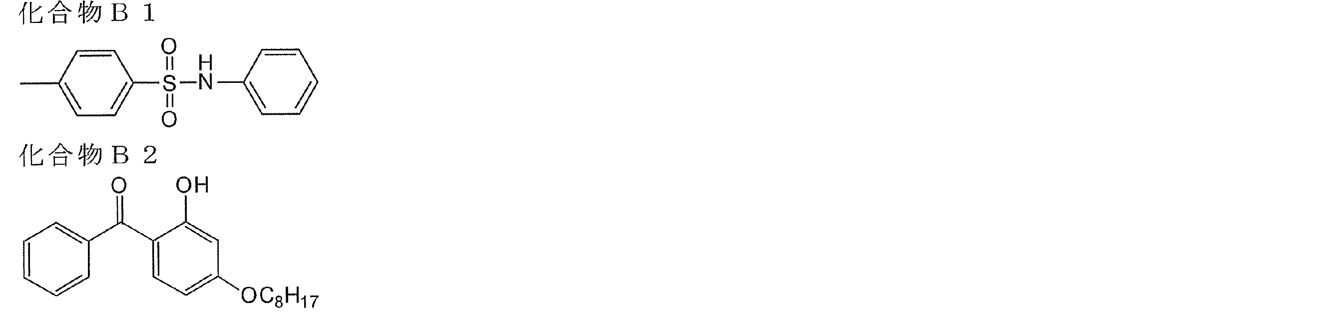
<セルロースアセテート保護フィルムの作製>
セルロースアシレート溶液Aを477質量部に、添加剤溶液Bの40質量部を添加し、充分に攪拌して、ドープを調製した。ドープを流延口から0℃に冷却したドラム上に流延した。溶媒含有率70質量%の場外で剥ぎ取り、フィルムの巾方向の両端をピンテンター(特開平4-1009号の図3に記載のピンテンター)で固定し、溶媒含有率が3~5質量%の状態で、横方向(機械方向に垂直な方向)の延伸率が3%となる間隔を保ちつつ乾燥した。その後、熱処理装置のロール間を搬送することにより、さらに乾燥し、厚み60μmのセルロースアセテート保護フィルムを作製した。保護フィルムの正面Reは2.0nmであった。
セルロースアシレート溶液Aを477質量部に、添加剤溶液Bの40質量部を添加し、充分に攪拌して、ドープを調製した。ドープを流延口から0℃に冷却したドラム上に流延した。溶媒含有率70質量%の場外で剥ぎ取り、フィルムの巾方向の両端をピンテンター(特開平4-1009号の図3に記載のピンテンター)で固定し、溶媒含有率が3~5質量%の状態で、横方向(機械方向に垂直な方向)の延伸率が3%となる間隔を保ちつつ乾燥した。その後、熱処理装置のロール間を搬送することにより、さらに乾燥し、厚み60μmのセルロースアセテート保護フィルムを作製した。保護フィルムの正面Reは2.0nmであった。
(直線偏光層の作製)
セルロースアセテート保護フィルムを、1.5規定の水酸化ナトリウム水溶液に、55℃で2分間浸漬した。室温の水洗浴槽中で洗浄し、30℃で0.1規定の硫酸を用いて中和した。再度、室温の水洗浴槽中で洗浄し、さらに100℃の温風で乾燥した。このようにして、セルロースアシレート保護フィルムの表面をケン化した。
続いて、厚さ80μmのロール状ポリビニルアルコールフィルムをヨウ素水溶液中で連続して5倍に延伸し、乾燥して直線偏光膜を得た。ポリビニルアルコール(クラレ製PVA-117H)3%水溶液を接着剤として、アルカリけん化処理したセルロースアシレート保護フィルムを2枚用意して直線偏光膜を間にして貼り合わせ、両面がセルロースアシレート保護フィルムによって保護された直線偏光層を得た。この際、両側のセルロースアシレートフィルム保護フィルムの遅相軸が直線偏光膜の透過軸と平行になるように貼り付けた。
セルロースアセテート保護フィルムを、1.5規定の水酸化ナトリウム水溶液に、55℃で2分間浸漬した。室温の水洗浴槽中で洗浄し、30℃で0.1規定の硫酸を用いて中和した。再度、室温の水洗浴槽中で洗浄し、さらに100℃の温風で乾燥した。このようにして、セルロースアシレート保護フィルムの表面をケン化した。
続いて、厚さ80μmのロール状ポリビニルアルコールフィルムをヨウ素水溶液中で連続して5倍に延伸し、乾燥して直線偏光膜を得た。ポリビニルアルコール(クラレ製PVA-117H)3%水溶液を接着剤として、アルカリけん化処理したセルロースアシレート保護フィルムを2枚用意して直線偏光膜を間にして貼り合わせ、両面がセルロースアシレート保護フィルムによって保護された直線偏光層を得た。この際、両側のセルロースアシレートフィルム保護フィルムの遅相軸が直線偏光膜の透過軸と平行になるように貼り付けた。
(パターニングされた位相差層の作製)
<剥離層用塗布液CU-1の調製>
下記の組成物を調製し、孔径30μmのポリプロピレン製フィルタでろ過して、剥離層用塗布液CU-1として用いた。
B-1はメチルメタクリレート、2-エチルヘキシルアクリレート、ベンジルメタクリレート及びメタクリル酸の共重合体で共重合組成比(モル比)=55/30/10/5、重量平均分子量=10万、Tg≒70℃である。
B-2はスチレンとアクリル酸の共重合体で共重合組成比(モル比)=65/35、重量平均分子量=1万、Tg≒100℃である。
──────────────────────────────────
力学特性制御層用塗布液組成(%)
──────────────────────────────────
バインダー(B-1) 5.89
バインダー(B-2) 3.74
BPE-500(新中村化学(株)製) 9.20
メガファックF-780-F(大日本インキ化学工業(株)製) 0.55
メタノール 11.22
プロピレングリコールモノメチルエーテルアセテート 6.43
メチルエチルケトン 52.97
──────────────────────────────────
<剥離層用塗布液CU-1の調製>
下記の組成物を調製し、孔径30μmのポリプロピレン製フィルタでろ過して、剥離層用塗布液CU-1として用いた。
B-1はメチルメタクリレート、2-エチルヘキシルアクリレート、ベンジルメタクリレート及びメタクリル酸の共重合体で共重合組成比(モル比)=55/30/10/5、重量平均分子量=10万、Tg≒70℃である。
B-2はスチレンとアクリル酸の共重合体で共重合組成比(モル比)=65/35、重量平均分子量=1万、Tg≒100℃である。
──────────────────────────────────
力学特性制御層用塗布液組成(%)
──────────────────────────────────
バインダー(B-1) 5.89
バインダー(B-2) 3.74
BPE-500(新中村化学(株)製) 9.20
メガファックF-780-F(大日本インキ化学工業(株)製) 0.55
メタノール 11.22
プロピレングリコールモノメチルエーテルアセテート 6.43
メチルエチルケトン 52.97
──────────────────────────────────
<配向層用塗布液AL-1の調製>
下記の組成物を調製し、孔径30μmのポリプロピレン製フィルタでろ過して、配向層用塗布液AL-1として用いた。
──────────────────────────────────
配向層用塗布液組成(%)
──────────────────────────────────
ポリビニルアルコール(PVA205、クラレ(株)製) 3.21
ポリビニルピロリドン(Luvitec K30、BASF社製)1.48
蒸留水 52.10
メタノール 43.21
──────────────────────────────────
下記の組成物を調製し、孔径30μmのポリプロピレン製フィルタでろ過して、配向層用塗布液AL-1として用いた。
──────────────────────────────────
配向層用塗布液組成(%)
──────────────────────────────────
ポリビニルアルコール(PVA205、クラレ(株)製) 3.21
ポリビニルピロリドン(Luvitec K30、BASF社製)1.48
蒸留水 52.10
メタノール 43.21
──────────────────────────────────
<位相差層用塗布液LC-1の調製>
下記の組成物を調製後、孔径0.2μmのポリプロピレン製フィルタでろ過して、位相差層用塗布液LC-1として用いた。
I-22は2つの反応性基を有する液晶化合物であり、2つの反応性基の片方はラジカル性の反応性基であるアクリル基、他方はカチオン性の反応性基であるオキセタニル基である。
──────────────────────────────────
位相差層用塗布液組成(%)
──────────────────────────────────
棒状液晶(I-22) 32.59
水平配向剤(LC-1-2) 0.02
カチオン系光重合開始剤(CPI100-P、サンアプロ株式会社製)0.66
重合制御剤(IRGANOX1076、
チバ・スペシャルティ・ケミカルズ(株)製) 0.07
メチルエチルケトン 66.66
──────────────────────────────────
下記の組成物を調製後、孔径0.2μmのポリプロピレン製フィルタでろ過して、位相差層用塗布液LC-1として用いた。
I-22は2つの反応性基を有する液晶化合物であり、2つの反応性基の片方はラジカル性の反応性基であるアクリル基、他方はカチオン性の反応性基であるオキセタニル基である。
──────────────────────────────────
位相差層用塗布液組成(%)
──────────────────────────────────
棒状液晶(I-22) 32.59
水平配向剤(LC-1-2) 0.02
カチオン系光重合開始剤(CPI100-P、サンアプロ株式会社製)0.66
重合制御剤(IRGANOX1076、
チバ・スペシャルティ・ケミカルズ(株)製) 0.07
メチルエチルケトン 66.66
──────────────────────────────────


(ラジカル重合開始剤供給層用塗布液AD-1の調製)
下記の組成物を調製後、孔径0.2μmのポリプロピレン製フィルタでろ過して、ラジカル重合開始剤供給層用塗布液AD-1として用いた。
B-3はベンジルメタクリレート、メタクリル酸及びメタクリル酸メチルの共重合体で共重合組成比(モル比)=35.9/22.4/41.7、重量平均分子量=3.8万である。
RPI-1としては2-トリクロロメチル-5-(p-スチリルスチリル)1,3,4-オキサジアゾールを用いた。
下記の組成物を調製後、孔径0.2μmのポリプロピレン製フィルタでろ過して、ラジカル重合開始剤供給層用塗布液AD-1として用いた。
B-3はベンジルメタクリレート、メタクリル酸及びメタクリル酸メチルの共重合体で共重合組成比(モル比)=35.9/22.4/41.7、重量平均分子量=3.8万である。
RPI-1としては2-トリクロロメチル-5-(p-スチリルスチリル)1,3,4-オキサジアゾールを用いた。
──────────────────────────────────
ラジカル重合開始剤供給層用塗布液組成(質量%)
──────────────────────────────────
バインダー(B-3) 8.05
KAYARAD DPHA(日本化薬(株)製) 4.83
ラジカル光重合開始剤(RPI-1) 0.12
ハイドロキノンモノメチルエーテル 0.002
メガファックF-176PF(大日本インキ化学工業(株)製) 0.05
プロピレングリコールモノメチルエーテルアセテート 34.80
メチルエチルケトン 50.538
メタノール 1.61
──────────────────────────────────
ラジカル重合開始剤供給層用塗布液組成(質量%)
──────────────────────────────────
バインダー(B-3) 8.05
KAYARAD DPHA(日本化薬(株)製) 4.83
ラジカル光重合開始剤(RPI-1) 0.12
ハイドロキノンモノメチルエーテル 0.002
メガファックF-176PF(大日本インキ化学工業(株)製) 0.05
プロピレングリコールモノメチルエーテルアセテート 34.80
メチルエチルケトン 50.538
メタノール 1.61
──────────────────────────────────
<パターニングされた位相差層の作製>
厚さ75μmのポリイミドフィルム仮支持体の上に、ワイヤーバーを用いて順に、剥離層用塗布液CU-1、配向層用塗布液AL-1を塗布、乾燥した。乾燥膜厚はそれぞれ14.6μm、1.6μmであった。次いで、ワイヤーバーを用いて位相差層用塗布液LC-1を塗布、膜面温度90℃で2分間乾燥して液晶相状態とした後、空気下にて160W/cm2の空冷メタルハライドランプ(アイグラフィックス(株)製)を用いて紫外線を照射してその配向状態を固定化して厚さ3.2μmの位相差層を形成した。この際用いた紫外線の照度はUV-A領域(波長320nm~400nmの積算)において100mW/cm2、照射量はUV-A領域において80mJ/cm2であった。さらに、位相差層上にラジカル重合開始剤供給層用塗布液AD-1を塗布、乾燥して1.2μmのラジカル重合開始剤供給層を形成した後、ミカサ社製M-3L露光装置とフォトマスクIを用いて露光量50mJ/cm2でパターン露光を行った。その後、温度230℃のクリーンオーブンで、1時間のベークを行うことにより未露光部分を等方相で熱固定化し、パターニングされた1/2波長層を作製した。該パターニングされた1/2波長層の、測定波長550nmにおける露光部の面内レターデーションは275nm(1/2波長)であり、未露光部の面内レターデーションは0nmであった。
この様にして、直線偏光板とパターニング1/2波長層との積層体を作製した。直線偏光板の吸収軸と、1/2波長のドメインの面内遅相軸とを45°で交差させて積層した。
厚さ75μmのポリイミドフィルム仮支持体の上に、ワイヤーバーを用いて順に、剥離層用塗布液CU-1、配向層用塗布液AL-1を塗布、乾燥した。乾燥膜厚はそれぞれ14.6μm、1.6μmであった。次いで、ワイヤーバーを用いて位相差層用塗布液LC-1を塗布、膜面温度90℃で2分間乾燥して液晶相状態とした後、空気下にて160W/cm2の空冷メタルハライドランプ(アイグラフィックス(株)製)を用いて紫外線を照射してその配向状態を固定化して厚さ3.2μmの位相差層を形成した。この際用いた紫外線の照度はUV-A領域(波長320nm~400nmの積算)において100mW/cm2、照射量はUV-A領域において80mJ/cm2であった。さらに、位相差層上にラジカル重合開始剤供給層用塗布液AD-1を塗布、乾燥して1.2μmのラジカル重合開始剤供給層を形成した後、ミカサ社製M-3L露光装置とフォトマスクIを用いて露光量50mJ/cm2でパターン露光を行った。その後、温度230℃のクリーンオーブンで、1時間のベークを行うことにより未露光部分を等方相で熱固定化し、パターニングされた1/2波長層を作製した。該パターニングされた1/2波長層の、測定波長550nmにおける露光部の面内レターデーションは275nm(1/2波長)であり、未露光部の面内レターデーションは0nmであった。
この様にして、直線偏光板とパターニング1/2波長層との積層体を作製した。直線偏光板の吸収軸と、1/2波長のドメインの面内遅相軸とを45°で交差させて積層した。
[立体画像印刷物の作製]
作製した直線偏光板及びパターニング1/2波長層の積層体と、作製したリバーサル画像とを貼合した。右眼用画素がReが1/2波長の第2のドメインに相当する部分に形成されている場合、左眼用画素はReが0nmの第1のドメインに相当する部分に形成されて、一方、右眼用画素がReが0nmの第1のドメインに相当する部分に形成されている場合、左眼用画素はReが1/2波長である第2のドメインに相当する部分に形成した。
この立体画像印刷物を、観察者が直線偏光メガネを介して観察した。観察された立体画像は、クロストークやゴースト像のない鮮明な立体画像であり、特に奥行き感に優れていた。
作製した直線偏光板及びパターニング1/2波長層の積層体と、作製したリバーサル画像とを貼合した。右眼用画素がReが1/2波長の第2のドメインに相当する部分に形成されている場合、左眼用画素はReが0nmの第1のドメインに相当する部分に形成されて、一方、右眼用画素がReが0nmの第1のドメインに相当する部分に形成されている場合、左眼用画素はReが1/2波長である第2のドメインに相当する部分に形成した。
この立体画像印刷物を、観察者が直線偏光メガネを介して観察した。観察された立体画像は、クロストークやゴースト像のない鮮明な立体画像であり、特に奥行き感に優れていた。
28.実施例3-4
[立体画像用印画物の作製]
保護層作製時の添加剤溶液Bから添加剤B1(Re低下剤)、及び添加剤B2(波長分散制御剤)を除いた以外は、実施例3-3と同様に立体画像用印刷物を作製した。このときの保護層(セルロースアセテート保護フィルム)の厚みは200μmであり、550nmにおけるRe値は15nm、Rthは85nmであった。
[立体画像用印画物の作製]
保護層作製時の添加剤溶液Bから添加剤B1(Re低下剤)、及び添加剤B2(波長分散制御剤)を除いた以外は、実施例3-3と同様に立体画像用印刷物を作製した。このときの保護層(セルロースアセテート保護フィルム)の厚みは200μmであり、550nmにおけるRe値は15nm、Rthは85nmであった。
立体画像の観察
観察者が偏光メガネを介して前記立体画像印刷物を観察したところ立体画像は観察可能であったが、該保護層の高いReにより、若干のゴースト像が認識されてしまった。
観察者が偏光メガネを介して前記立体画像印刷物を観察したところ立体画像は観察可能であったが、該保護層の高いReにより、若干のゴースト像が認識されてしまった。
29.実施例3-5
(直線偏光層の作製)
実施例3-1で作製したパターニング位相差板1の支持体であるTACフィルム(厚さ80μm)の裏面(パターニング1/4波長層が形成されていない側の面)に、クラレ社製ポリビニルアルコール「PVA103」の4%水溶液を、12番バーで塗布を行い、80℃で5分間乾燥させた。その後に、400rpmで3往復ラビング処理を行い、ラビング配向膜付保護層を作製した。配向膜の厚さは0.5μmであった。
(直線偏光層の作製)
実施例3-1で作製したパターニング位相差板1の支持体であるTACフィルム(厚さ80μm)の裏面(パターニング1/4波長層が形成されていない側の面)に、クラレ社製ポリビニルアルコール「PVA103」の4%水溶液を、12番バーで塗布を行い、80℃で5分間乾燥させた。その後に、400rpmで3往復ラビング処理を行い、ラビング配向膜付保護層を作製した。配向膜の厚さは0.5μmであった。
クロロホルム99質量部に下記構造のイエローアゾ色素A2-3(一般式(II)の化合物) 0.24質量部、下記構造のマゼンタアゾ色素A-46(一般式(I)の化合物) 0.33質量部、下記構造のシアンアゾ色素A3-1(一般式(III)の化合物) 0.37質量部、及び下記構造のスクアリリウム色素VI-5 0.06質量部を加え、撹拌溶解後、濾過して直線偏光層用塗布液を得た。次に、前記ラビング配向膜上に、該塗布液を塗布し、室温で自然乾燥して直線偏光層を作製した。得られた直線偏光層の厚さは0.4μmであり、二色比は42であった。また、直線偏光用組成物は、サーモトロピック液晶性を有しており、そのアイソトロピック相転移温度は240℃であった。
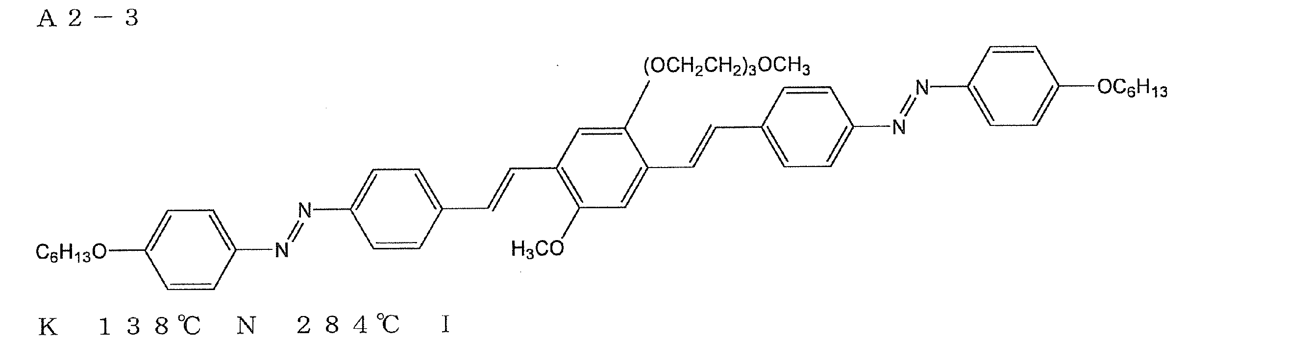


(酸素遮断層用塗布液の調製)
下記組成物をミキシングタンクに投入し、攪拌して酸素遮断層用塗布液とした。
ポリビニルアルコール(PVA205(商品名、クラレ(株)製)3.2質量部、ポリビニルピロリドン(PVP K-30(商品名、日本触媒(株)製)1.5質量部、メタノール44質量部、水56質量部を添加して攪拌した。孔径0.4μmのポリプロピレン製フィルタで濾過して酸素遮断層用塗布液を調製した。
下記組成物をミキシングタンクに投入し、攪拌して酸素遮断層用塗布液とした。
ポリビニルアルコール(PVA205(商品名、クラレ(株)製)3.2質量部、ポリビニルピロリドン(PVP K-30(商品名、日本触媒(株)製)1.5質量部、メタノール44質量部、水56質量部を添加して攪拌した。孔径0.4μmのポリプロピレン製フィルタで濾過して酸素遮断層用塗布液を調製した。
(酸素遮断層の作製)
前記記載の、直線偏光層の上層に、前記酸素遮断層用塗布液を塗布し、100℃で2分間乾燥し酸素遮断層を作製した。酸素遮断層の厚さは1μmであり、面内レターデーションReは0nmであった。
前記記載の、直線偏光層の上層に、前記酸素遮断層用塗布液を塗布し、100℃で2分間乾燥し酸素遮断層を作製した。酸素遮断層の厚さは1μmであり、面内レターデーションReは0nmであった。
(透明樹脂硬化層用塗布液の調製)
下記組成物をミキシングタンクに投入し、攪拌して透明樹脂硬化層塗布液とした。
トリメチロールプロパントリアクリレート(ビスコート#295(商品名、大阪有機化学(株)製)7.5質量部に、質量平均分子量15000のポリ(グリシジルメタクリレート)2.7質量部、メチルエチルケトン7.3質量部、シクロヘキサノン5.0質量部及び光重合開始剤(イルガキュア184(商品名)、チバ・スペシャルティ・ケミカルズ(株)製)0.5質量部を添加して攪拌した。孔径0.4μmのポリプロピレン製フィルタで濾過して透明樹脂硬化層用の塗布液を調製した。
下記組成物をミキシングタンクに投入し、攪拌して透明樹脂硬化層塗布液とした。
トリメチロールプロパントリアクリレート(ビスコート#295(商品名、大阪有機化学(株)製)7.5質量部に、質量平均分子量15000のポリ(グリシジルメタクリレート)2.7質量部、メチルエチルケトン7.3質量部、シクロヘキサノン5.0質量部及び光重合開始剤(イルガキュア184(商品名)、チバ・スペシャルティ・ケミカルズ(株)製)0.5質量部を添加して攪拌した。孔径0.4μmのポリプロピレン製フィルタで濾過して透明樹脂硬化層用の塗布液を調製した。
(透明樹脂硬化層用塗布液の作製)
前記酸素遮断層の上層に、該透明樹脂硬化層用塗布液を塗布し、100℃で2分間乾燥した。その後、窒素雰囲気下(酸素濃度100ppm以下)5Jの紫外線を照射して重合し、直線偏光層(層厚0.4μm)の表面に、層厚1μmの酸素遮断層、層厚2μmの透明樹脂硬化層が順次積層された積層体を作製した。透明樹脂硬化層の面内レターデーションReは0nmであった。
前記酸素遮断層の上層に、該透明樹脂硬化層用塗布液を塗布し、100℃で2分間乾燥した。その後、窒素雰囲気下(酸素濃度100ppm以下)5Jの紫外線を照射して重合し、直線偏光層(層厚0.4μm)の表面に、層厚1μmの酸素遮断層、層厚2μmの透明樹脂硬化層が順次積層された積層体を作製した。透明樹脂硬化層の面内レターデーションReは0nmであった。
この様にして、直線偏光層と、パターニング1/4波長層である位相差板1との積層体を作製した。
この積層体を用いた以外は、実施例3-1と同様にして、この積層体と、リバーサル画像(実施例3-1と同様の方法で作製)とを貼合し、立体画像印刷物を作製した。
この立体画像印刷物を、観察者が円偏光メガネを介して観察したところ、観察された立体画像は、実施例3-1と同様、クロストークやゴースト像のない鮮明な立体画像であり、特に奥行き感に優れていた。
また、観察者が円偏光メガネを介して前記立体画像印刷物をパターニングされた1/4波長層の0°の方向(図2に示す偏光軸cの方向)に30度傾けて観察しても、ほとんどクロストークが認識されず、鮮明な立体画像を観察することができた。
前記立体画像印刷物は、パターニング1/4波長層と画像受像層の距離dは100.8μmであり、パターン幅pは200μmであり、d/pは0.50であるためクロストークが発生しないと考えられる。
さらに、実施例3-1の立体画像印刷物と比較して、直線偏光膜が薄層で高い二色比を達成しているので、より明るい立体画像として認識された。
この積層体を用いた以外は、実施例3-1と同様にして、この積層体と、リバーサル画像(実施例3-1と同様の方法で作製)とを貼合し、立体画像印刷物を作製した。
この立体画像印刷物を、観察者が円偏光メガネを介して観察したところ、観察された立体画像は、実施例3-1と同様、クロストークやゴースト像のない鮮明な立体画像であり、特に奥行き感に優れていた。
また、観察者が円偏光メガネを介して前記立体画像印刷物をパターニングされた1/4波長層の0°の方向(図2に示す偏光軸cの方向)に30度傾けて観察しても、ほとんどクロストークが認識されず、鮮明な立体画像を観察することができた。
前記立体画像印刷物は、パターニング1/4波長層と画像受像層の距離dは100.8μmであり、パターン幅pは200μmであり、d/pは0.50であるためクロストークが発生しないと考えられる。
さらに、実施例3-1の立体画像印刷物と比較して、直線偏光膜が薄層で高い二色比を達成しているので、より明るい立体画像として認識された。
30.実施例3-6
直線偏光層作製時の直線偏光層用組成物を、下記組成に変更した以外は、実施例3-5と同様に立体画像用印刷物を作製した。このときの直線偏光層の厚みは0.4μmであり、二色比は37であった。
直線偏光層作製時の直線偏光層用組成物を、下記組成に変更した以外は、実施例3-5と同様に立体画像用印刷物を作製した。このときの直線偏光層の厚みは0.4μmであり、二色比は37であった。
<直線偏光層用組成物>
(1)イエローアゾ色素A2-3 0.2質量部
(2)マゼンタアゾ色素C-9 0.4質量部
(3)シアンアゾ色素A3-1 0.4質量部
(4)クロロホルム 99質量部
(1)イエローアゾ色素A2-3 0.2質量部
(2)マゼンタアゾ色素C-9 0.4質量部
(3)シアンアゾ色素A3-1 0.4質量部
(4)クロロホルム 99質量部

[立体画像の観察]
観察者が円偏光メガネを介して前記立体画像印刷物を観察したところ、実施例3-5と同様、明るい、クロストークやゴースト像のない鮮明な立体画像を観察することができた。
さらに、観察者が円偏光メガネを介して前記立体画像印刷物をパターニングされた1/4波長層の0°の方向(図2に示す偏光軸cの方向)に30度傾けて観察しても、ほとんどクロストークが認識されず、鮮明な立体画像を観察することができた。
前記立体画像印刷物は、パターニング1/4波長層と画像受像層の距離dは100.8μmであり、パターン幅pは200μmであり、d/pは0.50であるためクロストークが発生しないと考えられる。
観察者が円偏光メガネを介して前記立体画像印刷物を観察したところ、実施例3-5と同様、明るい、クロストークやゴースト像のない鮮明な立体画像を観察することができた。
さらに、観察者が円偏光メガネを介して前記立体画像印刷物をパターニングされた1/4波長層の0°の方向(図2に示す偏光軸cの方向)に30度傾けて観察しても、ほとんどクロストークが認識されず、鮮明な立体画像を観察することができた。
前記立体画像印刷物は、パターニング1/4波長層と画像受像層の距離dは100.8μmであり、パターン幅pは200μmであり、d/pは0.50であるためクロストークが発生しないと考えられる。
31.実施例3-7
[立体画像用印画物の作製]
直線偏光層作製時の直線偏光層用組成物を、下記組成に変更した以外は、実施例3-5と同様に立体画像用印刷物を作製した。このときの直線偏光層の厚みは0.8μmであり、二色比は71であった。
[立体画像用印画物の作製]
直線偏光層作製時の直線偏光層用組成物を、下記組成に変更した以外は、実施例3-5と同様に立体画像用印刷物を作製した。このときの直線偏光層の厚みは0.8μmであり、二色比は71であった。
<直線偏光層用組成物>
(1)マゼンタアゾ色素A-16 1.2質量部
(2)マゼンタアゾ色素B-4 0.8質量部
(3)クロロホルム 98質量部
(1)マゼンタアゾ色素A-16 1.2質量部
(2)マゼンタアゾ色素B-4 0.8質量部
(3)クロロホルム 98質量部


[立体画像の観察]
観察者が円偏光メガネを介して前記立体画像印刷物を観察したところ、実施例3-5と同様、明るい、クロストークやゴースト像のない鮮明な立体画像を観察することができた。
また、観察者が円偏光メガネを介して前記立体画像印刷物をパターニングされた1/4波長層の0°の方向(図2に示す偏光軸cの方向)に30度傾けて観察しても、ほとんどクロストークが認識されず、鮮明な立体画像を観察することができた。
前記立体画像印刷物は、パターニング1/4波長層と画像受像層の距離dは101.2μmであり、パターン幅pは200μmであり、d/pは0.50であるためクロストークが発生しないと考えられる。
観察者が円偏光メガネを介して前記立体画像印刷物を観察したところ、実施例3-5と同様、明るい、クロストークやゴースト像のない鮮明な立体画像を観察することができた。
また、観察者が円偏光メガネを介して前記立体画像印刷物をパターニングされた1/4波長層の0°の方向(図2に示す偏光軸cの方向)に30度傾けて観察しても、ほとんどクロストークが認識されず、鮮明な立体画像を観察することができた。
前記立体画像印刷物は、パターニング1/4波長層と画像受像層の距離dは101.2μmであり、パターン幅pは200μmであり、d/pは0.50であるためクロストークが発生しないと考えられる。
32.実施例3-8
[立体画像用印画物の作製]
厚さ100μm、正面Re=1nmの保護フィルムに変更した以外は、実施例3-2と同様に立体画像用印刷物を作製した。
[立体画像用印画物の作製]
厚さ100μm、正面Re=1nmの保護フィルムに変更した以外は、実施例3-2と同様に立体画像用印刷物を作製した。
[立体画像の観察]
観察者が円偏光メガネを介して前記立体画像印刷物を観察したところ、実施例3-2と同様、明るい、クロストークやゴースト像のない鮮明な立体画像を観察することができた。
しかしながら、観察者が円偏光メガネを介して前記立体画像印刷物をパターニングされた1/4波長層の0°の方向(図2に示す偏光軸cの方向)に30度傾けて観察したところ、立体画像として認識できるものの、クロストークも観察された。
前記立体画像印刷物は、パターニング1/4波長層と画像受像層の距離dは146μmであり、パターン幅pは200μmであり、d/pは0.73であるためクロストークが観察されたと考えられる。
観察者が円偏光メガネを介して前記立体画像印刷物を観察したところ、実施例3-2と同様、明るい、クロストークやゴースト像のない鮮明な立体画像を観察することができた。
しかしながら、観察者が円偏光メガネを介して前記立体画像印刷物をパターニングされた1/4波長層の0°の方向(図2に示す偏光軸cの方向)に30度傾けて観察したところ、立体画像として認識できるものの、クロストークも観察された。
前記立体画像印刷物は、パターニング1/4波長層と画像受像層の距離dは146μmであり、パターン幅pは200μmであり、d/pは0.73であるためクロストークが観察されたと考えられる。
33.実施例3-9
[立体画像用印画物の作製]
厚さ600μm、正面Re=1nmの保護フィルムに変更した以外は、実施例3-2と同様に立体画像用印刷物を作製した。
[立体画像用印画物の作製]
厚さ600μm、正面Re=1nmの保護フィルムに変更した以外は、実施例3-2と同様に立体画像用印刷物を作製した。
[立体画像の観察]
観察者が円偏光メガネを介して前記立体画像印刷物を観察したところ、実施例3-2と同様、明るい、クロストークやゴースト像のない鮮明な立体画像を観察することができた。
しかしながら、観察者が円偏光メガネを介して前記立体画像印刷物をパターニングされた1/4波長層の0°の方向(図2に示す偏光軸cの方向)に30度傾けて観察したところ、立体画像として認識できるものの、クロストークが大きく観察された。
前記立体画像印刷物は、パターニング1/4波長層と画像受像層の距離dは646μmであり、パターン幅pは200μmであり、d/pは3.23であるためクロストークが大きく観察されたと考えられる。
観察者が円偏光メガネを介して前記立体画像印刷物を観察したところ、実施例3-2と同様、明るい、クロストークやゴースト像のない鮮明な立体画像を観察することができた。
しかしながら、観察者が円偏光メガネを介して前記立体画像印刷物をパターニングされた1/4波長層の0°の方向(図2に示す偏光軸cの方向)に30度傾けて観察したところ、立体画像として認識できるものの、クロストークが大きく観察された。
前記立体画像印刷物は、パターニング1/4波長層と画像受像層の距離dは646μmであり、パターン幅pは200μmであり、d/pは3.23であるためクロストークが大きく観察されたと考えられる。
34.比較例3-1
リバーサルフィルムの代わりに、リバーサルフィルムから乳剤層を取り去り、支持体フィルムのみを配置した以外は、実施例3-1で作製したのと同様の構成の積層体を作製した。
実施例3-1と同様にして立体画像を観察したが、円偏光メガネで観察しても、立体画像として認識することはできなかった。
リバーサルフィルムの代わりに、リバーサルフィルムから乳剤層を取り去り、支持体フィルムのみを配置した以外は、実施例3-1で作製したのと同様の構成の積層体を作製した。
実施例3-1と同様にして立体画像を観察したが、円偏光メガネで観察しても、立体画像として認識することはできなかった。
10A~10I、20A~20J 立体画像用印画紙
12、22 光透過性画像受像層
14、24 直線偏光層
14a、14b 直線偏光層の保護層
15、25 配向層
16 1/4波長層
17 粘着剤層
26 パターニング位相差層
18 光透過性支持体
18’ 支持体
19 反射層
30 重合開始剤供給層
12、22 光透過性画像受像層
14、24 直線偏光層
14a、14b 直線偏光層の保護層
15、25 配向層
16 1/4波長層
17 粘着剤層
26 パターニング位相差層
18 光透過性支持体
18’ 支持体
19 反射層
30 重合開始剤供給層
Claims (23)
- 光透過性画像受像層、直線偏光層、及び位相差層をこの順で有し、前記位相差層が、屈折率異方性を有する化合物を含む組成物を、配向状態に固定して形成された層であり、且つ面内遅相軸が互いに異なる方向にある、又は面内レターデーションが互いに異なる第1及び第2のドメインにパターニングされていることを特徴とする立体画像印刷用印画紙。
- 前記位相差層が、前記組成物を、塗布手段、吹き付け手段及び滴下手段のいずれかの手段により、適用してなることを特徴とする請求項1に記載の印画紙。
- 前記光透過性画像受像層が、塗布手段、吹き付け手段及び滴下手段のいずれかの手段により形成された層であることを特徴とする請求項1又は2に記載の印画紙。
- 前記光透過性画像受像層が、銀塩写真法、感熱転写法、又はインクジェット法により画像受像可能な画像受像層であることを特徴とする請求項1~3のいずれか1項に記載の印画紙。
- 前記位相差層が、1/4波長層であって、第1及び第2のドメインの面内遅相軸が互いに90°をなし、第1のドメインの面内遅相軸及び第2のドメインの面内遅相軸のそれぞれが、前記直線偏光層の偏光軸と±45°の角度をなしていることを特徴とする請求項1~4のいずれか1項に記載の印画紙。
- 前記位相差層の第1のドメインの面内レターデーションが0であり、第2のドメインの面内レターデーションが1/2波長であり、前記直線偏光層の偏光軸と第2のドメインの面内遅相軸とが45°の角度をなしていることを特徴とする請求項1~4のいずれか1項に記載の印画紙。
- 前記直線偏光層が、二色性色素を含む液晶性組成物を塗布することにより形成された塗布型の直線偏光層であることを特徴とする請求項1~6のいずれか1項に記載の印画紙。
- 前記位相差層が、硬化性液晶性組成物を硬化してなることを特徴とする請求項1~7のいずれか1項に記載の印画紙。
- 前記位相差層が、パターン露光された光配向膜によって配向制御された硬化性液晶性組成物を硬化してなることを特徴とする請求項8に記載の印画紙。
- 前記直線偏光層と前記位相差層との間に、波長550nmにおける面内レターデーションRe(550)が、0~10nmである、前記直線偏光層の保護層をさらに有することを特徴とする請求項1~9のいずれか1項に記載の印画紙。
- 前記保護層及び前記位相差層の、波長550nmにおける厚み方向レターデーションRth(550)の合計の絶対値が、20nm以下であることを特徴とする請求項10に記載の印画紙。
- 前記光透過性画像受像層が、銀塩写真法により画像受像可能な画像受像層であり、青感光性乳剤層、緑感光性乳剤層、及び赤感光性乳剤層を有することを特徴とする請求項1~11のいずれか1項に記載の印画紙。
- 前記光透過性画像受像層が、感熱転写法により画像受像可能な画像受像層であり、染色性受容ポリマーの少なくとも1種を含有することを特徴とする請求項1~11のいずれか1項に記載の印画紙。
- 前記画像受像層が、インクジェット法により画像受像可能な画像受像層であり、水溶性高分子及び無機微粒子を少なくとも含む組成物からなることを特徴とする請求項1~11のいずれか1項に記載の印画紙。
- 前記直線偏光層が、下記一般式(I)、下記一般式(II)、下記一般式(III)、下記一般式(IV)、又は下記一般式(VI)で表わされる二色性色素の少なくとも一種を含有する液晶性組成物からなることを特徴とする請求項1~14のいずれか1項に記載の印画紙。





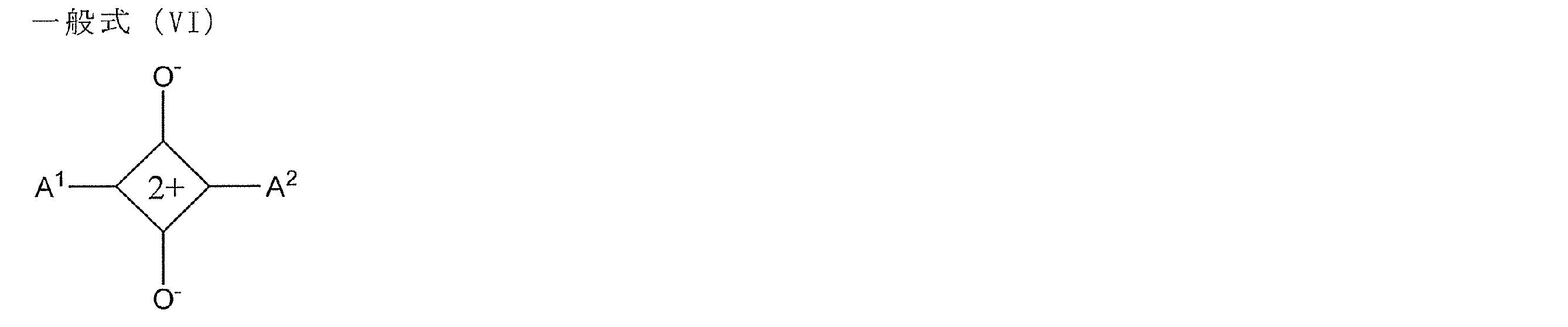
- 前記位相差層と前記画像受像層との間の距離dが、500μm以下である請求項1~15のいずれか1項に記載の印画紙。
- 前記位相差層と前記画像受像層との間の距離dと、前記第1及び第2のドメインのパターン境界線の間隔pとの比(d/p)が、3以下である請求項1~16のいずれか1項に記載の印画紙。
- 請求項1~17のいずれか1項に記載の印画紙と、該印画紙の光透過性画像受像層に形成された視差のある左眼用画像及び右眼用画像とを有する立体画像印刷物であって、該左眼用画像及び右眼用画像のそれぞれを構成する画素が、前記印画紙の位相差層の第1のドメイン及び第2のドメインに対応する位置に形成されていることを特徴とする立体画像印刷物。
- 観察者の視認側と反対の面に、非偏光解消性の反射層をさらに有することを特徴とする請求項18に記載の立体画像印刷物。
- 請求項1~13のいずれか1項に記載の印画紙の光透過性画像受像層に、ライトジェット法により視差のある左眼用画像及び右眼用画像を、前記印画紙の位相差層の第1のドメイン及び第2のドメインに対応する位置にそれぞれ形成することを含む立体画像印刷物の製造方法。
- 請求項1~12及び14のいずれか1項に記載の印画紙の光透過性画像受像層に、色素を含有する感熱転写シートを重ね合わせること、
電気信号によって発熱が制御されるサーマルヘッドによって該感熱転写シートを加熱して、視差のある左眼用画像及び右眼用画像を、前記印画紙の位相差層の第1のドメイン及び第2のドメインに対応する位置にそれぞれ、色素を転写することで形成すること;
を含む立体画像印刷物の製造方法。 - 請求項1~12及び15のいずれか1項に記載の印画紙の光透過性画像受像層に、インクジェット法により、視差のある左眼用画像及び右眼用画像を、前記印画紙の位相差層の第1のドメイン及び第2のドメインに対応する位置にそれぞれ形成することを含む立体画像印刷物の製造方法。
- 請求項18又は19に記載の立体画像印刷物を準備すること、
該立体画像印刷物を、左眼用及び右眼用のレンズが、互いに逆向きの円偏光レンズ、又は偏光軸が互いに直交した直線偏光レンズである、偏光メガネを着用した観察者に対して表示すること、
を含む立体画像の提供方法。
Priority Applications (2)
| Application Number | Priority Date | Filing Date | Title |
|---|---|---|---|
| CN201180026290.1A CN102906606B (zh) | 2010-05-28 | 2011-05-27 | 用于印刷立体图像的印刷纸、立体图像印刷物、制备立体图像印刷物的方法及提供立体图像的方法 |
| US13/685,065 US20130083276A1 (en) | 2010-05-28 | 2012-11-26 | Printing sheet for printing stereo picture, stereo picture print, method of manufacturing stereo picture print, and method of providing stereo picture |
Applications Claiming Priority (8)
| Application Number | Priority Date | Filing Date | Title |
|---|---|---|---|
| JP2010122728 | 2010-05-28 | ||
| JP2010-122729 | 2010-05-28 | ||
| JP2010-122728 | 2010-05-28 | ||
| JP2010122729 | 2010-05-28 | ||
| JP2010-170602 | 2010-07-29 | ||
| JP2010170602 | 2010-07-29 | ||
| JP2010-242855 | 2010-10-28 | ||
| JP2010242855 | 2010-10-28 |
Related Child Applications (1)
| Application Number | Title | Priority Date | Filing Date |
|---|---|---|---|
| US13/685,065 Continuation US20130083276A1 (en) | 2010-05-28 | 2012-11-26 | Printing sheet for printing stereo picture, stereo picture print, method of manufacturing stereo picture print, and method of providing stereo picture |
Publications (1)
| Publication Number | Publication Date |
|---|---|
| WO2011149038A1 true WO2011149038A1 (ja) | 2011-12-01 |
Family
ID=45004021
Family Applications (1)
| Application Number | Title | Priority Date | Filing Date |
|---|---|---|---|
| PCT/JP2011/062164 Ceased WO2011149038A1 (ja) | 2010-05-28 | 2011-05-27 | 立体画像印刷用印画紙、立体画像印刷物、立体画像印刷物の製造方法、及び立体画像の提供方法 |
Country Status (4)
| Country | Link |
|---|---|
| US (1) | US20130083276A1 (ja) |
| JP (1) | JP5749568B2 (ja) |
| CN (1) | CN102906606B (ja) |
| WO (1) | WO2011149038A1 (ja) |
Cited By (5)
| Publication number | Priority date | Publication date | Assignee | Title |
|---|---|---|---|---|
| CN102717617A (zh) * | 2012-07-06 | 2012-10-10 | 武汉大学 | 一种立体打印相纸的制备方法 |
| JP2013134394A (ja) * | 2011-12-27 | 2013-07-08 | Fujifilm Corp | パターン位相差フィルム、その製造方法、光学積層体の製造方法、3d画像表示装置、及びマスク |
| WO2013154073A1 (ja) * | 2012-04-10 | 2013-10-17 | 富士フイルム株式会社 | 光学異方性を有する積層体 |
| WO2018096879A1 (ja) * | 2016-11-25 | 2018-05-31 | 富士フイルム株式会社 | 光学物品の製造方法、及び光学物品 |
| CN118087309A (zh) * | 2024-03-30 | 2024-05-28 | 湖南科技大学 | 一种可循环使用的可见光打印纸制备方法及应用 |
Families Citing this family (40)
| Publication number | Priority date | Publication date | Assignee | Title |
|---|---|---|---|---|
| JP5566160B2 (ja) * | 2010-03-31 | 2014-08-06 | 富士フイルム株式会社 | 液晶性化合物、液晶性組成物、光吸収異方性膜、及び液晶表示装置 |
| JP2012123040A (ja) * | 2010-12-06 | 2012-06-28 | Nitto Denko Corp | 位相差層付偏光板 |
| JP6029246B2 (ja) * | 2011-11-17 | 2016-11-24 | エルジー・ケム・リミテッド | 光学素子およびこれを含む立体映像表示装置 |
| TWI588540B (zh) * | 2012-05-09 | 2017-06-21 | 半導體能源研究所股份有限公司 | 顯示裝置和電子裝置 |
| JP6123563B2 (ja) * | 2012-08-31 | 2017-05-10 | 住友化学株式会社 | 円偏光板および表示装置 |
| KR101565321B1 (ko) | 2012-12-13 | 2015-11-03 | 동우 화인켐 주식회사 | 편광판 및 이를 포함하는 화상 표시 장치 |
| JP6021851B2 (ja) * | 2013-05-10 | 2016-11-09 | 富士フイルム株式会社 | 吸湿材料及びその製造方法並びに包装材料 |
| JP6132678B2 (ja) * | 2013-06-21 | 2017-05-24 | 富士フイルム株式会社 | 偏光フィルターおよびその応用 |
| JP6153895B2 (ja) * | 2013-07-22 | 2017-06-28 | 富士フイルム株式会社 | 液晶表示装置 |
| KR102174761B1 (ko) * | 2013-08-14 | 2020-11-06 | 삼성디스플레이 주식회사 | 플렉서블 표시장치 및 그 제조방법 |
| CN103605176A (zh) * | 2013-09-17 | 2014-02-26 | 京东方科技集团股份有限公司 | 相位差膜及其制造方法和显示设备 |
| KR102131117B1 (ko) * | 2014-02-07 | 2020-07-08 | 삼성디스플레이 주식회사 | 편광자, 편광자를 갖는 표시 장치, 및 편광자 제조 방법 |
| US9869809B2 (en) * | 2014-03-12 | 2018-01-16 | Dai Nippon Printing Co., Ltd. | Backlight unit, liquid-crystal display apparatus, and stacked structure |
| KR102426386B1 (ko) * | 2014-04-18 | 2022-07-27 | 스미또모 가가꾸 가부시키가이샤 | 패턴 편광 필름 및 그의 제조 방법 |
| JP6667983B2 (ja) * | 2014-05-30 | 2020-03-18 | 富士フイルム株式会社 | 積層体およびその製造方法、偏光板、液晶表示装置、有機el表示装置 |
| WO2016072966A1 (en) | 2014-11-03 | 2016-05-12 | Hewlett-Packard Development Company, L.P. | Thermally decomposing material for three-dimensional printing |
| CN107111225B (zh) | 2014-12-23 | 2021-07-27 | 普利司通美国轮胎运营有限责任公司 | 聚合物产品的增材制造方法 |
| CN104597711B (zh) * | 2015-02-13 | 2021-05-28 | 厦门天马微电子有限公司 | 一种光罩、其制作方法及基板图案的制作方法 |
| JP6810060B2 (ja) | 2015-06-09 | 2021-01-06 | ダウ グローバル テクノロジーズ エルエルシー | 3d印刷用支持材料 |
| TWI717401B (zh) * | 2015-10-20 | 2021-02-01 | 南韓商東友精細化工有限公司 | 整合有偏光板之窗口基板、及製備該窗口基板之方法 |
| JP7338945B2 (ja) * | 2015-10-30 | 2023-09-05 | 住友化学株式会社 | 偏光板 |
| US11097531B2 (en) | 2015-12-17 | 2021-08-24 | Bridgestone Americas Tire Operations, Llc | Additive manufacturing cartridges and processes for producing cured polymeric products by additive manufacturing |
| KR102027567B1 (ko) * | 2016-02-19 | 2019-10-01 | 삼성에스디아이 주식회사 | 기능성 광학필름 및 이를 포함하는 투명 디스플레이 장치 |
| JP6821492B2 (ja) * | 2016-04-08 | 2021-01-27 | 日本化薬株式会社 | 光反射フィルム、ならびにこれを用いた光学フィルム、機能性ガラスおよびヘッドアップディスプレイ |
| JP2018036586A (ja) | 2016-09-02 | 2018-03-08 | 日東電工株式会社 | 光学部材 |
| JP2018036585A (ja) * | 2016-09-02 | 2018-03-08 | 日東電工株式会社 | 光学部材 |
| WO2018079130A1 (ja) * | 2016-10-25 | 2018-05-03 | 富士フイルム株式会社 | 透過加飾フィルム |
| US11453161B2 (en) | 2016-10-27 | 2022-09-27 | Bridgestone Americas Tire Operations, Llc | Processes for producing cured polymeric products by additive manufacturing |
| WO2019130582A1 (ja) * | 2017-12-28 | 2019-07-04 | 日立化成株式会社 | 積層体、波長変換部材、バックライトユニット、及び画像表示装置 |
| WO2020072060A1 (en) * | 2018-10-03 | 2020-04-09 | Moxtek, Inc. | Durable, high performance wire grid polarizer |
| EP3850407A4 (en) * | 2018-10-12 | 2022-10-05 | Gary Sharp Innovations, Inc. | POLARIZATION BASED FILTERS WITH ANGLE SENSITIVE TRANSMISSION |
| KR102774293B1 (ko) * | 2018-11-20 | 2025-02-26 | 엘지디스플레이 주식회사 | 유기 발광 소자 |
| KR102246299B1 (ko) * | 2019-03-12 | 2021-04-29 | 주식회사 온빛 | 고굴절 편광렌즈의 제조방법 |
| CN110264916B (zh) * | 2019-06-21 | 2022-05-10 | 京东方科技集团股份有限公司 | 一种投影装置及空中成像设备 |
| US11339250B2 (en) * | 2019-06-26 | 2022-05-24 | Skc Co., Ltd. | Polyamide-imide film and process for preparing the same |
| JP7324851B2 (ja) * | 2019-08-23 | 2023-08-10 | 富士フイルム株式会社 | 光学積層体、パターン光学異方性層の製造方法、3d画像表示装置および3d画像表示システム |
| EP3865302B1 (en) * | 2020-02-14 | 2024-08-14 | iSQUARED AG | Copolymer for use in a digital manufacturing process |
| US11656394B2 (en) * | 2021-03-04 | 2023-05-23 | Liqxtal Technology Inc. | Sensing device |
| WO2025142815A1 (ja) * | 2023-12-27 | 2025-07-03 | 富士フイルム株式会社 | 積層体、複合レンズ、表示装置、仮想現実表示装置 |
| CN119360751B (zh) * | 2024-12-26 | 2026-01-16 | 浙江怡钛积科技有限公司 | 带fpr液晶相位差补偿层的oled显示面板及其制备方法、光学应用装置 |
Citations (4)
| Publication number | Priority date | Publication date | Assignee | Title |
|---|---|---|---|---|
| JPH05210182A (ja) * | 1991-06-13 | 1993-08-20 | Shinko Electric Co Ltd | 立体画像印刷物製造方法 |
| JPH0895176A (ja) * | 1994-07-27 | 1996-04-12 | Tomohiko Hattori | 光学システムに使用される偏光フイルムおよびこの偏光フイルムを用いた立体画像表示装置 |
| JP2001059949A (ja) * | 1999-06-15 | 2001-03-06 | Arisawa Mfg Co Ltd | 3d映像表示体の製造方法及び3d映像表示体形成用のフィルム |
| JP2008257207A (ja) * | 2007-03-30 | 2008-10-23 | Arisawa Mfg Co Ltd | 立体画像表示装置の製造方法、位相差板の製造方法および位相差板 |
Family Cites Families (17)
| Publication number | Priority date | Publication date | Assignee | Title |
|---|---|---|---|---|
| ATE173978T1 (de) * | 1995-01-31 | 1998-12-15 | Rowland Inst For Science | Beschichtungsverfahren und zusammensetzungen zur herstellung von stereoskopischen, polarisierenden, digitalisierten bildern |
| US6013123A (en) * | 1995-01-31 | 2000-01-11 | The Rowland Institute For Science | Inking methods and compositions for production of digitized stereoscopic polarizing images |
| JP3360787B2 (ja) * | 1996-12-02 | 2002-12-24 | シャープ株式会社 | 立体表示装置 |
| JP2002040604A (ja) * | 2000-07-21 | 2002-02-06 | Fuji Photo Film Co Ltd | ハロゲン化銀カラー写真感光材料 |
| JP2005141086A (ja) * | 2003-11-07 | 2005-06-02 | Sony Corp | 液晶表示装置およびその製造方法 |
| EP1624337A3 (en) * | 2004-08-02 | 2006-04-19 | Fuji Photo Film Co., Ltd. | Silver halide holographic sensitive material and system for taking holographic images by using the same |
| JP2006126700A (ja) * | 2004-11-01 | 2006-05-18 | Konica Minolta Photo Imaging Inc | 立体画像形成方法 |
| GB2428344A (en) * | 2005-07-08 | 2007-01-24 | Sharp Kk | Multiple view directional display |
| JP4587945B2 (ja) * | 2005-11-30 | 2010-11-24 | 富士フイルム株式会社 | 感熱転写受像シートおよびその製造方法 |
| JP2007185874A (ja) * | 2006-01-13 | 2007-07-26 | Fujifilm Corp | インクジェット記録媒体 |
| JP5131510B2 (ja) * | 2006-07-18 | 2013-01-30 | Nltテクノロジー株式会社 | 液晶表示装置、及び端末装置 |
| JP2009041007A (ja) * | 2007-07-18 | 2009-02-26 | Toray Ind Inc | 光学等方性アクリル樹脂フィルムの製造方法およびその製造方法 |
| US20090274853A1 (en) * | 2008-03-31 | 2009-11-05 | Fujifilm Corporation | Dichroic dye composition |
| JP5112147B2 (ja) * | 2008-03-31 | 2013-01-09 | 富士フイルム株式会社 | 偏光素子、および偏光素子の製造方法 |
| JP2009251288A (ja) * | 2008-04-07 | 2009-10-29 | Nitto Denko Corp | 楕円偏光板並びにその製造方法 |
| JP4547641B2 (ja) * | 2008-09-22 | 2010-09-22 | ソニー株式会社 | 位相差板の製造方法 |
| US20100245998A1 (en) * | 2009-03-27 | 2010-09-30 | Microcontinuum, Inc. | Stereoscopic Image Formation Techniques |
-
2011
- 2011-05-24 JP JP2011115600A patent/JP5749568B2/ja not_active Expired - Fee Related
- 2011-05-27 WO PCT/JP2011/062164 patent/WO2011149038A1/ja not_active Ceased
- 2011-05-27 CN CN201180026290.1A patent/CN102906606B/zh active Active
-
2012
- 2012-11-26 US US13/685,065 patent/US20130083276A1/en not_active Abandoned
Patent Citations (4)
| Publication number | Priority date | Publication date | Assignee | Title |
|---|---|---|---|---|
| JPH05210182A (ja) * | 1991-06-13 | 1993-08-20 | Shinko Electric Co Ltd | 立体画像印刷物製造方法 |
| JPH0895176A (ja) * | 1994-07-27 | 1996-04-12 | Tomohiko Hattori | 光学システムに使用される偏光フイルムおよびこの偏光フイルムを用いた立体画像表示装置 |
| JP2001059949A (ja) * | 1999-06-15 | 2001-03-06 | Arisawa Mfg Co Ltd | 3d映像表示体の製造方法及び3d映像表示体形成用のフィルム |
| JP2008257207A (ja) * | 2007-03-30 | 2008-10-23 | Arisawa Mfg Co Ltd | 立体画像表示装置の製造方法、位相差板の製造方法および位相差板 |
Cited By (8)
| Publication number | Priority date | Publication date | Assignee | Title |
|---|---|---|---|---|
| JP2013134394A (ja) * | 2011-12-27 | 2013-07-08 | Fujifilm Corp | パターン位相差フィルム、その製造方法、光学積層体の製造方法、3d画像表示装置、及びマスク |
| WO2013154073A1 (ja) * | 2012-04-10 | 2013-10-17 | 富士フイルム株式会社 | 光学異方性を有する積層体 |
| CN104204877A (zh) * | 2012-04-10 | 2014-12-10 | 富士胶片株式会社 | 具有光学各向异性的层积体 |
| CN102717617A (zh) * | 2012-07-06 | 2012-10-10 | 武汉大学 | 一种立体打印相纸的制备方法 |
| WO2018096879A1 (ja) * | 2016-11-25 | 2018-05-31 | 富士フイルム株式会社 | 光学物品の製造方法、及び光学物品 |
| CN109891279A (zh) * | 2016-11-25 | 2019-06-14 | 富士胶片株式会社 | 光学物品的制造方法及光学物品 |
| CN118087309A (zh) * | 2024-03-30 | 2024-05-28 | 湖南科技大学 | 一种可循环使用的可见光打印纸制备方法及应用 |
| CN118087309B (zh) * | 2024-03-30 | 2025-12-05 | 湖南科技大学 | 一种可循环使用的可见光打印纸制备方法及应用 |
Also Published As
| Publication number | Publication date |
|---|---|
| JP5749568B2 (ja) | 2015-07-15 |
| JP2012108465A (ja) | 2012-06-07 |
| CN102906606A (zh) | 2013-01-30 |
| US20130083276A1 (en) | 2013-04-04 |
| CN102906606B (zh) | 2014-12-10 |
Similar Documents
| Publication | Publication Date | Title |
|---|---|---|
| JP5749568B2 (ja) | 立体画像印刷用印画紙、立体画像印刷物、立体画像印刷物の製造方法、及び立体画像の提供方法 | |
| JP5244889B2 (ja) | 立体画像印刷用印画紙、立体画像印刷物、及び立体画像の提供方法 | |
| JP2012000907A (ja) | 立体画像印刷物、及びその製造方法 | |
| WO2011158937A1 (ja) | 立体画像印刷物、及びその製造方法 | |
| JP6001874B2 (ja) | 光学積層体及び光学積層体の製造方法 | |
| JP5481306B2 (ja) | 積層体、光学フィルムおよびそれらの製造方法、偏光板、画像晶表示装置、立体画像表示システム | |
| JP6309026B2 (ja) | 光学シート部材及び表示装置 | |
| JP5695532B2 (ja) | 光学フィルム、その製造方法、並びにそれを用いた偏光板、画像表示装置及び立体画像表示システム | |
| JP5427449B2 (ja) | 二色性色素組成物を用いた光吸収異方性膜、偏光素子、該偏光子の製造方法および液晶表示装置 | |
| JP5827906B2 (ja) | 積層体、及びその用途 | |
| US10642145B2 (en) | Transparent screen and image display system | |
| JP2013092707A (ja) | 調光用偏光板、及びシャッター用偏光板 | |
| JP2013047789A (ja) | 光学フィルム、セキュリティ製品、および真贋判定方法 | |
| CN107850721A (zh) | 层叠体及窗 | |
| JP7428785B2 (ja) | 液晶表示装置 | |
| WO2004015464A1 (en) | Retarder and circular polarizer | |
| KR101729819B1 (ko) | 편광 소자 | |
| JP2013061372A (ja) | フィルム・パターンド・リターダーの製造方法、並びにフィルム・パターンド・リターダー、及びそれを有する偏光板及び画像表示装置 | |
| JP2013029552A (ja) | 光学フィルムおよび立体画像表示装置 | |
| JP2012032507A (ja) | 偏光眼鏡 | |
| JP2010230924A (ja) | 光吸収異方性膜の製造方法及び光吸収異方性膜 | |
| JP2011248201A (ja) | 立体画像印刷用印画紙、立体画像印刷物、立体画像印刷方法、及び立体画像の提供方法 | |
| JP6487777B2 (ja) | 積層体、窓および積層体の製造方法 | |
| KR20180023655A (ko) | 편광 소자 및 이의 용도 | |
| JP2007212492A (ja) | 光学補償フィルム、偏光板、及び液晶表示装置 |
Legal Events
| Date | Code | Title | Description |
|---|---|---|---|
| WWE | Wipo information: entry into national phase |
Ref document number: 201180026290.1 Country of ref document: CN |
|
| 121 | Ep: the epo has been informed by wipo that ep was designated in this application |
Ref document number: 11786735 Country of ref document: EP Kind code of ref document: A1 |
|
| NENP | Non-entry into the national phase |
Ref country code: DE |
|
| 122 | Ep: pct application non-entry in european phase |
Ref document number: 11786735 Country of ref document: EP Kind code of ref document: A1 |