WO2011148753A1 - Dispositif de régulation de la force d'appui sur la pédale d'accélérateur d'un véhicule hybride - Google Patents
Dispositif de régulation de la force d'appui sur la pédale d'accélérateur d'un véhicule hybride Download PDFInfo
- Publication number
- WO2011148753A1 WO2011148753A1 PCT/JP2011/060305 JP2011060305W WO2011148753A1 WO 2011148753 A1 WO2011148753 A1 WO 2011148753A1 JP 2011060305 W JP2011060305 W JP 2011060305W WO 2011148753 A1 WO2011148753 A1 WO 2011148753A1
- Authority
- WO
- WIPO (PCT)
- Prior art keywords
- accelerator opening
- opening degree
- accelerator
- accelerator pedal
- depression force
- Prior art date
Links
- 230000000881 depressing effect Effects 0.000 title abstract 3
- 230000007423 decrease Effects 0.000 claims description 15
- 238000002485 combustion reaction Methods 0.000 claims description 7
- 230000001133 acceleration Effects 0.000 abstract description 6
- 230000001105 regulatory effect Effects 0.000 abstract 1
- 230000005540 biological transmission Effects 0.000 description 19
- 230000008859 change Effects 0.000 description 6
- 230000007246 mechanism Effects 0.000 description 6
- 238000000034 method Methods 0.000 description 5
- 230000008569 process Effects 0.000 description 5
- 238000001514 detection method Methods 0.000 description 4
- 238000006243 chemical reaction Methods 0.000 description 3
- 239000000446 fuel Substances 0.000 description 3
- 230000008878 coupling Effects 0.000 description 2
- 238000010168 coupling process Methods 0.000 description 2
- 238000005859 coupling reaction Methods 0.000 description 2
- 230000000994 depressogenic effect Effects 0.000 description 2
- 230000006866 deterioration Effects 0.000 description 2
- 238000010586 diagram Methods 0.000 description 2
- 238000004891 communication Methods 0.000 description 1
- 230000003247 decreasing effect Effects 0.000 description 1
- 238000005516 engineering process Methods 0.000 description 1
- 238000004880 explosion Methods 0.000 description 1
- 239000012530 fluid Substances 0.000 description 1
- 238000002347 injection Methods 0.000 description 1
- 239000007924 injection Substances 0.000 description 1
- 238000007562 laser obscuration time method Methods 0.000 description 1
- 238000010248 power generation Methods 0.000 description 1
- 230000001172 regenerating effect Effects 0.000 description 1
- 230000007704 transition Effects 0.000 description 1
Images


Classifications
-
- B—PERFORMING OPERATIONS; TRANSPORTING
- B60—VEHICLES IN GENERAL
- B60W—CONJOINT CONTROL OF VEHICLE SUB-UNITS OF DIFFERENT TYPE OR DIFFERENT FUNCTION; CONTROL SYSTEMS SPECIALLY ADAPTED FOR HYBRID VEHICLES; ROAD VEHICLE DRIVE CONTROL SYSTEMS FOR PURPOSES NOT RELATED TO THE CONTROL OF A PARTICULAR SUB-UNIT
- B60W20/00—Control systems specially adapted for hybrid vehicles
- B60W20/10—Controlling the power contribution of each of the prime movers to meet required power demand
- B60W20/15—Control strategies specially adapted for achieving a particular effect
-
- B—PERFORMING OPERATIONS; TRANSPORTING
- B60—VEHICLES IN GENERAL
- B60K—ARRANGEMENT OR MOUNTING OF PROPULSION UNITS OR OF TRANSMISSIONS IN VEHICLES; ARRANGEMENT OR MOUNTING OF PLURAL DIVERSE PRIME-MOVERS IN VEHICLES; AUXILIARY DRIVES FOR VEHICLES; INSTRUMENTATION OR DASHBOARDS FOR VEHICLES; ARRANGEMENTS IN CONNECTION WITH COOLING, AIR INTAKE, GAS EXHAUST OR FUEL SUPPLY OF PROPULSION UNITS IN VEHICLES
- B60K6/00—Arrangement or mounting of plural diverse prime-movers for mutual or common propulsion, e.g. hybrid propulsion systems comprising electric motors and internal combustion engines ; Control systems therefor, i.e. systems controlling two or more prime movers, or controlling one of these prime movers and any of the transmission, drive or drive units Informative references: mechanical gearings with secondary electric drive F16H3/72; arrangements for handling mechanical energy structurally associated with the dynamo-electric machine H02K7/00; machines comprising structurally interrelated motor and generator parts H02K51/00; dynamo-electric machines not otherwise provided for in H02K see H02K99/00
- B60K6/20—Arrangement or mounting of plural diverse prime-movers for mutual or common propulsion, e.g. hybrid propulsion systems comprising electric motors and internal combustion engines ; Control systems therefor, i.e. systems controlling two or more prime movers, or controlling one of these prime movers and any of the transmission, drive or drive units Informative references: mechanical gearings with secondary electric drive F16H3/72; arrangements for handling mechanical energy structurally associated with the dynamo-electric machine H02K7/00; machines comprising structurally interrelated motor and generator parts H02K51/00; dynamo-electric machines not otherwise provided for in H02K see H02K99/00 the prime-movers consisting of electric motors and internal combustion engines, e.g. HEVs
- B60K6/42—Arrangement or mounting of plural diverse prime-movers for mutual or common propulsion, e.g. hybrid propulsion systems comprising electric motors and internal combustion engines ; Control systems therefor, i.e. systems controlling two or more prime movers, or controlling one of these prime movers and any of the transmission, drive or drive units Informative references: mechanical gearings with secondary electric drive F16H3/72; arrangements for handling mechanical energy structurally associated with the dynamo-electric machine H02K7/00; machines comprising structurally interrelated motor and generator parts H02K51/00; dynamo-electric machines not otherwise provided for in H02K see H02K99/00 the prime-movers consisting of electric motors and internal combustion engines, e.g. HEVs characterised by the architecture of the hybrid electric vehicle
- B60K6/48—Parallel type
-
- B—PERFORMING OPERATIONS; TRANSPORTING
- B60—VEHICLES IN GENERAL
- B60K—ARRANGEMENT OR MOUNTING OF PROPULSION UNITS OR OF TRANSMISSIONS IN VEHICLES; ARRANGEMENT OR MOUNTING OF PLURAL DIVERSE PRIME-MOVERS IN VEHICLES; AUXILIARY DRIVES FOR VEHICLES; INSTRUMENTATION OR DASHBOARDS FOR VEHICLES; ARRANGEMENTS IN CONNECTION WITH COOLING, AIR INTAKE, GAS EXHAUST OR FUEL SUPPLY OF PROPULSION UNITS IN VEHICLES
- B60K26/00—Arrangements or mounting of propulsion unit control devices in vehicles
- B60K26/02—Arrangements or mounting of propulsion unit control devices in vehicles of initiating means or elements
- B60K26/021—Arrangements or mounting of propulsion unit control devices in vehicles of initiating means or elements with means for providing feel, e.g. by changing pedal force characteristics
-
- B—PERFORMING OPERATIONS; TRANSPORTING
- B60—VEHICLES IN GENERAL
- B60K—ARRANGEMENT OR MOUNTING OF PROPULSION UNITS OR OF TRANSMISSIONS IN VEHICLES; ARRANGEMENT OR MOUNTING OF PLURAL DIVERSE PRIME-MOVERS IN VEHICLES; AUXILIARY DRIVES FOR VEHICLES; INSTRUMENTATION OR DASHBOARDS FOR VEHICLES; ARRANGEMENTS IN CONNECTION WITH COOLING, AIR INTAKE, GAS EXHAUST OR FUEL SUPPLY OF PROPULSION UNITS IN VEHICLES
- B60K26/00—Arrangements or mounting of propulsion unit control devices in vehicles
- B60K26/04—Arrangements or mounting of propulsion unit control devices in vehicles of means connecting initiating means or elements to propulsion unit
-
- B—PERFORMING OPERATIONS; TRANSPORTING
- B60—VEHICLES IN GENERAL
- B60L—PROPULSION OF ELECTRICALLY-PROPELLED VEHICLES; SUPPLYING ELECTRIC POWER FOR AUXILIARY EQUIPMENT OF ELECTRICALLY-PROPELLED VEHICLES; ELECTRODYNAMIC BRAKE SYSTEMS FOR VEHICLES IN GENERAL; MAGNETIC SUSPENSION OR LEVITATION FOR VEHICLES; MONITORING OPERATING VARIABLES OF ELECTRICALLY-PROPELLED VEHICLES; ELECTRIC SAFETY DEVICES FOR ELECTRICALLY-PROPELLED VEHICLES
- B60L50/00—Electric propulsion with power supplied within the vehicle
- B60L50/10—Electric propulsion with power supplied within the vehicle using propulsion power supplied by engine-driven generators, e.g. generators driven by combustion engines
- B60L50/16—Electric propulsion with power supplied within the vehicle using propulsion power supplied by engine-driven generators, e.g. generators driven by combustion engines with provision for separate direct mechanical propulsion
-
- B—PERFORMING OPERATIONS; TRANSPORTING
- B60—VEHICLES IN GENERAL
- B60W—CONJOINT CONTROL OF VEHICLE SUB-UNITS OF DIFFERENT TYPE OR DIFFERENT FUNCTION; CONTROL SYSTEMS SPECIALLY ADAPTED FOR HYBRID VEHICLES; ROAD VEHICLE DRIVE CONTROL SYSTEMS FOR PURPOSES NOT RELATED TO THE CONTROL OF A PARTICULAR SUB-UNIT
- B60W10/00—Conjoint control of vehicle sub-units of different type or different function
- B60W10/04—Conjoint control of vehicle sub-units of different type or different function including control of propulsion units
- B60W10/06—Conjoint control of vehicle sub-units of different type or different function including control of propulsion units including control of combustion engines
-
- B—PERFORMING OPERATIONS; TRANSPORTING
- B60—VEHICLES IN GENERAL
- B60W—CONJOINT CONTROL OF VEHICLE SUB-UNITS OF DIFFERENT TYPE OR DIFFERENT FUNCTION; CONTROL SYSTEMS SPECIALLY ADAPTED FOR HYBRID VEHICLES; ROAD VEHICLE DRIVE CONTROL SYSTEMS FOR PURPOSES NOT RELATED TO THE CONTROL OF A PARTICULAR SUB-UNIT
- B60W10/00—Conjoint control of vehicle sub-units of different type or different function
- B60W10/04—Conjoint control of vehicle sub-units of different type or different function including control of propulsion units
- B60W10/08—Conjoint control of vehicle sub-units of different type or different function including control of propulsion units including control of electric propulsion units, e.g. motors or generators
-
- B—PERFORMING OPERATIONS; TRANSPORTING
- B60—VEHICLES IN GENERAL
- B60W—CONJOINT CONTROL OF VEHICLE SUB-UNITS OF DIFFERENT TYPE OR DIFFERENT FUNCTION; CONTROL SYSTEMS SPECIALLY ADAPTED FOR HYBRID VEHICLES; ROAD VEHICLE DRIVE CONTROL SYSTEMS FOR PURPOSES NOT RELATED TO THE CONTROL OF A PARTICULAR SUB-UNIT
- B60W20/00—Control systems specially adapted for hybrid vehicles
-
- B—PERFORMING OPERATIONS; TRANSPORTING
- B60—VEHICLES IN GENERAL
- B60W—CONJOINT CONTROL OF VEHICLE SUB-UNITS OF DIFFERENT TYPE OR DIFFERENT FUNCTION; CONTROL SYSTEMS SPECIALLY ADAPTED FOR HYBRID VEHICLES; ROAD VEHICLE DRIVE CONTROL SYSTEMS FOR PURPOSES NOT RELATED TO THE CONTROL OF A PARTICULAR SUB-UNIT
- B60W30/00—Purposes of road vehicle drive control systems not related to the control of a particular sub-unit, e.g. of systems using conjoint control of vehicle sub-units, or advanced driver assistance systems for ensuring comfort, stability and safety or drive control systems for propelling or retarding the vehicle
-
- B—PERFORMING OPERATIONS; TRANSPORTING
- B60—VEHICLES IN GENERAL
- B60W—CONJOINT CONTROL OF VEHICLE SUB-UNITS OF DIFFERENT TYPE OR DIFFERENT FUNCTION; CONTROL SYSTEMS SPECIALLY ADAPTED FOR HYBRID VEHICLES; ROAD VEHICLE DRIVE CONTROL SYSTEMS FOR PURPOSES NOT RELATED TO THE CONTROL OF A PARTICULAR SUB-UNIT
- B60W2510/00—Input parameters relating to a particular sub-units
- B60W2510/24—Energy storage means
- B60W2510/242—Energy storage means for electrical energy
- B60W2510/244—Charge state
-
- B—PERFORMING OPERATIONS; TRANSPORTING
- B60—VEHICLES IN GENERAL
- B60W—CONJOINT CONTROL OF VEHICLE SUB-UNITS OF DIFFERENT TYPE OR DIFFERENT FUNCTION; CONTROL SYSTEMS SPECIALLY ADAPTED FOR HYBRID VEHICLES; ROAD VEHICLE DRIVE CONTROL SYSTEMS FOR PURPOSES NOT RELATED TO THE CONTROL OF A PARTICULAR SUB-UNIT
- B60W2540/00—Input parameters relating to occupants
- B60W2540/10—Accelerator pedal position
- B60W2540/103—Accelerator thresholds, e.g. kickdown
-
- Y—GENERAL TAGGING OF NEW TECHNOLOGICAL DEVELOPMENTS; GENERAL TAGGING OF CROSS-SECTIONAL TECHNOLOGIES SPANNING OVER SEVERAL SECTIONS OF THE IPC; TECHNICAL SUBJECTS COVERED BY FORMER USPC CROSS-REFERENCE ART COLLECTIONS [XRACs] AND DIGESTS
- Y02—TECHNOLOGIES OR APPLICATIONS FOR MITIGATION OR ADAPTATION AGAINST CLIMATE CHANGE
- Y02T—CLIMATE CHANGE MITIGATION TECHNOLOGIES RELATED TO TRANSPORTATION
- Y02T10/00—Road transport of goods or passengers
- Y02T10/60—Other road transportation technologies with climate change mitigation effect
- Y02T10/62—Hybrid vehicles
-
- Y—GENERAL TAGGING OF NEW TECHNOLOGICAL DEVELOPMENTS; GENERAL TAGGING OF CROSS-SECTIONAL TECHNOLOGIES SPANNING OVER SEVERAL SECTIONS OF THE IPC; TECHNICAL SUBJECTS COVERED BY FORMER USPC CROSS-REFERENCE ART COLLECTIONS [XRACs] AND DIGESTS
- Y02—TECHNOLOGIES OR APPLICATIONS FOR MITIGATION OR ADAPTATION AGAINST CLIMATE CHANGE
- Y02T—CLIMATE CHANGE MITIGATION TECHNOLOGIES RELATED TO TRANSPORTATION
- Y02T10/00—Road transport of goods or passengers
- Y02T10/60—Other road transportation technologies with climate change mitigation effect
- Y02T10/70—Energy storage systems for electromobility, e.g. batteries
-
- Y—GENERAL TAGGING OF NEW TECHNOLOGICAL DEVELOPMENTS; GENERAL TAGGING OF CROSS-SECTIONAL TECHNOLOGIES SPANNING OVER SEVERAL SECTIONS OF THE IPC; TECHNICAL SUBJECTS COVERED BY FORMER USPC CROSS-REFERENCE ART COLLECTIONS [XRACs] AND DIGESTS
- Y02—TECHNOLOGIES OR APPLICATIONS FOR MITIGATION OR ADAPTATION AGAINST CLIMATE CHANGE
- Y02T—CLIMATE CHANGE MITIGATION TECHNOLOGIES RELATED TO TRANSPORTATION
- Y02T10/00—Road transport of goods or passengers
- Y02T10/60—Other road transportation technologies with climate change mitigation effect
- Y02T10/7072—Electromobility specific charging systems or methods for batteries, ultracapacitors, supercapacitors or double-layer capacitors
Definitions
- the present invention relates to an accelerator pedal depression force control device for a hybrid vehicle.
- Patent Document 1 in a hybrid vehicle including a motor and an internal combustion engine as a drive source of the vehicle, the vehicle is caused to travel by a combination of the motor and the internal combustion engine from a first traveling mode in which the motor travels solely by the motor.
- the drive mode is shifted against the driver's intention and the internal combustion engine is started and fuel consumption Technology has been disclosed that does not cause deterioration.
- the accelerator opening degree which increases the resistance to depression of the accelerator pedal can be variably set, when the accelerator opening degree which increases the resistance to depression of the accelerator pedal becomes smaller, the accelerator pedal There is a problem that it becomes difficult to step in and it becomes difficult to accelerate the vehicle.
- the predetermined accelerator opening degree threshold Is a first accelerator opening set on the basis of a mode switching accelerator opening that switches from a first traveling mode in which only the electric motor is driven to travel the vehicle to a second traveling mode in which the internal combustion engine is driven A predetermined lower limit value is set to the first accelerator opening degree.
- the present invention by setting the lower limit value for the first accelerator opening, it is possible to depress the accelerator pedal more than a fixed amount, and the acceleration of the vehicle can be secured.
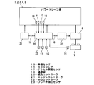
- FIG. 1 is a system configuration diagram of a hybrid vehicle to which the present invention is applied.
- Explanatory drawing which shows the example of a characteristic of an engine start / stop line map.
- Explanatory drawing which showed typically the system configuration of the accelerator pedal depression force control apparatus which concerns on this invention with the outline of a depression force change mechanism.
- Explanatory drawing which shows typically one Example of the treading force change mechanism in this invention.
- the characteristic view which shows the characteristic of the accelerator pedal depression force in the present invention.
- FIG. 1 is an explanatory view schematically showing a schematic configuration of a power train system of a hybrid vehicle to which the present invention is applied.
- An output shaft of an engine 1 which is an internal combustion engine and an input shaft of a motor generator 2 (MG) as a motor which also functions as a generator are connected via a first clutch 4 (CL1) of variable torque capacity.
- the output shaft of the motor generator 2 is connected to the input shaft of the automatic transmission 3 (AT), and the output shaft of the automatic transmission 3 is connected to the tire 7 via the differential gear 6.
- the automatic transmission 3 automatically switches (performs shift control), for example, a stepped gear ratio such as 5 forward speeds and 1 reverse speed or 6 forward speed and 1 reverse speed according to the vehicle speed and the accelerator opening degree. is there.
- the second clutch 5 is a plurality of friction coupling elements provided as the transmission elements of the automatic transmission 3 and uses the friction coupling elements present in the power transmission path of each shift stage. , Substantially inside the automatic transmission 3.
- the automatic transmission 3 combines the motive power of the engine 1 input through the first clutch 4 and the motive power input from the motor generator 2 and outputs the resultant to the tire 7.
- a wet multi-plate clutch capable of continuously controlling the flow rate and hydraulic pressure of hydraulic fluid with a proportional solenoid is used.
- the power train system has two operation modes according to the connection state of the first clutch 4. That is, when the first clutch 4 is disconnected, the EV mode travels with only the power of the motor generator 2, and when the first clutch 4 is connected, the HEV mode travels with the power of the engine 1 and the motor generator 2. It becomes.
- reference numeral 10 denotes an engine rotation sensor for detecting the rotation speed of the engine 1
- 11 denotes an MG rotation sensor for detecting the rotation speed of the motor generator 2
- 12 denotes an AT for detecting the input shaft rotation speed of the automatic transmission 3.
- An input rotation sensor 13 is an AT output rotation sensor that detects the output shaft rotation speed of the automatic transmission 2, and detection signals of these sensors are input to an integrated controller 20 described later.
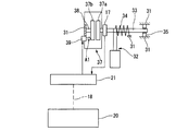
- FIG. 2 shows a system configuration diagram of a hybrid vehicle to which the present invention is applied.
- the hybrid vehicle includes an integrated controller 20 that integrally controls the vehicle, an engine controller 21 that controls the engine 1, and an MG controller 22 that controls the motor generator 2.
- the integrated controller 20 is connected to the engine controller 21 and the MG controller 22 via communication lines 18 capable of exchanging information with each other.
- the integrated controller 20 also includes a vehicle speed sensor 15 for detecting the vehicle speed. From the SOC sensor 16, which detects the state of charge (SOC) of the battery 9 that supplies power, the accelerator opening sensor 17, which detects the accelerator opening (APO), and the brake oil pressure sensor 23, which detects the brake oil pressure. A detection signal is input.
- the integrated controller 20 selects an operation mode capable of realizing the driving force desired by the driver according to the accelerator opening degree and the SOC of the battery 9 and the vehicle speed, and transmits the target MG torque or target MG rotation speed to the MG controller 22. It commands the engine controller 21 to command the target engine torque. The engagement and release of the first clutch 4 and the second clutch 5 are controlled based on a command from the integrated controller 20.
- the integrated controller 20 calculates the operation mode of the engine 1 using the vehicle speed and the accelerator opening. That is, using the engine start / stop line map as shown in FIG. 3, it is determined whether the engine is in an operation state to start or in an engine stop state.
- the engine start line and the engine stop line change in the direction in which the accelerator opening decreases (downward in FIG. 3) as the SOC of the battery 9 decreases. Further, if the SOC of the battery 9 is in the same state, the engine stop line is set to a direction in which the accelerator opening degree becomes smaller than that of the engine start line.
- the accelerator opening degree for stopping the engine 1 (accelerator opening on the engine stop line) is greater than the accelerator opening degree for starting the engine 1 (accelerator opening degree on the engine start line).
- Degree is set to be small.
- the torque capacity of the second clutch 5 is set so that the second clutch 5 slips to a half clutch state when the accelerator opening degree exceeds the engine start line shown in FIG.
- engagement of the first clutch 4 is started to increase the engine speed.
- the engine 1 is operated to completely engage the first clutch 4 when the MG speed and the engine speed become close, and then the second clutch 5 is locked. Up and transition to HEV mode.
- the engine controller 21 controls the engine 1 in accordance with a command from the integrated controller 20.
- the MG controller 22 controls an inverter 8 that drives the motor generator 2 in accordance with a command from the integrated controller 20.
- the motor generator 2 is controlled by the MG controller 22 in a power running operation to which the power supplied from the battery 9 is applied, a regenerative operation functioning as a generator to charge the battery 9, and switching between start and stop. There is.
- the output (current value) of the motor generator 2 is monitored by the MG controller 22.
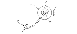
- FIG. 4 is an explanatory view schematically showing the system configuration of the accelerator pedal depression force control device together with the outline of the depression force change mechanism
- FIG. 5 is an explanatory view schematically showing one embodiment of the depression force change mechanism.
- the accelerator pedal depression force control device variably controls the depression force (operation reaction force) of an accelerator pedal 32 provided on a vehicle body 31 of a vehicle (not shown). In the region where the value of d is larger than the predetermined accelerator opening threshold, the depression force of the accelerator pedal 32 is increased more than the base depression force.
- the accelerator pedal 32 as shown in FIGS. 4 and 5, is provided on the rotary shaft 33 and configured to swing around the rotary shaft 33, and one end is fixed to the vehicle body 31 and the other end is Reaction forces in the accelerator closing direction are provided by return springs 34 of various forms fixed to the rotation shaft 33. Further, while one end of the rotation shaft 33 is rotatably supported by the vehicle body 31 via the bearing 35, the above-mentioned accelerator opening sensor 17 is provided near the other end of the rotation shaft 33 as an accelerator opening detection means. ing.
- the depression amount of the accelerator pedal 32 (accelerator opening degree) and the opening degree of the throttle valve (not shown) of the engine 1 interlock with each other, and the engine 1 is controlled according to the depression amount of the accelerator pedal 32.
- Throttle valve opening increases. That is, the fuel injection amount (and hence the fuel consumption amount) increases according to the accelerator opening degree.
- the treading force changing mechanism is composed of a variable friction plate 37 having a pair of friction members 37a and 37b facing each other for applying friction to the rotation of the rotation shaft 33.
- One friction member 7a is an end of the rotation shaft 3
- the other friction member 7b is axially movably and non-rotatably supported by the fixed shaft 38 via splines or the like.
- the fixed shaft 38 is fixed to and supported by the vehicle body 31.
- an actuator (for example, an electromagnetic solenoid) 39 that biases the friction member 37 b toward the friction member 37 a is fixed to the vehicle body 31.
- variable friction plate 37 moves the friction member 37b in the axial direction (direction of arrow A1 in FIG. 4) by the operation of the actuator 39, thereby variably controlling the friction force between the friction member 37a and the friction member 37b.
- the operation of the actuator 39 is controlled by the engine controller 21 based on a command from the integrated controller 20. Therefore, by controlling the operation of the actuator 39 by the engine controller 21, it is possible to change the frictional force applied to the rotary shaft 33 and hence the pedaling force when the accelerator pedal 32 is depressed.
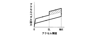
- FIG. 6 schematically shows the characteristics of the accelerator pedal depression force in the above embodiment, and the basic pedal depression force, that is, the base pedal depression force, has appropriate hysteresis in the opening degree increasing direction and the opening degree decreasing direction. It increases almost proportionally to the opening degree. Then, when the accelerator opening degree becomes larger than a predetermined accelerator opening degree threshold (symbol SL in FIG. 6) at the time of operation in the opening degree increasing direction, that is, when stepping on, the accelerator pedal depression force increases stepwise than the base depression force. As the accelerator pedal effort increases stepwise in this manner, further depression of the accelerator pedal 32 by the driver is naturally suppressed.
- a predetermined accelerator opening degree threshold symbol SL in FIG. 6
- the increase in the depression force of the accelerator pedal 32 in the direction of increasing the accelerator opening is canceled when the accelerator opening decreases below the predetermined opening, but the operation of the accelerator pedal 32 is When the direction reverses in the accelerator opening decrease direction, it may be released immediately.
- a second accelerator opening based on the accelerator opening which is a constant speed equal opening on a flat road in other words, a so-called R / L line (road road line necessary to drive the vehicle without acceleration or deceleration on a flat road surface ) Is set by the second accelerator opening degree set based on the upper accelerator opening degree.
- FIG. 7 is an explanatory view showing an example of the characteristic of the accelerator opening threshold, and FIG. 7 (a) shows an example of the characteristic when the battery SOC is high, and FIG. 7 (b) is a characteristic when the battery SOC is low An example is shown.
- the first accelerator opening degree (dotted line in FIG. 7) is an accelerator opening degree on the engine start line (solid line in FIG. 7), which is a threshold value for switching from EV travel to HEV travel, It is an opening degree.
- the accelerator opening amount ⁇ is set in consideration of the opening degree which is depressed before the accelerator pedal 32 is stopped by feeling the pedal reaction force.
- the second accelerator opening degree (two-dot chain line in FIG. 7) is constant at an accelerator opening degree at constant speed on a flat road at each vehicle speed (accelerator opening degree on R / L line, one-dot chain line in FIG. 7)
- the accelerator opening degree is obtained by adding an accelerator opening degree ⁇ capable of securing an accelerating driving force.
- the engine start line changes in the direction (lower in FIG. 7) in which the accelerator opening decreases when the SOC of the battery 9 decreases. It decreases when it decreases.
- the accelerator opening threshold is set only with the first accelerator opening, the accelerator opening threshold relatively decreases as the SOC of the battery 9 decreases. Therefore, the accelerator pedal 32 is used when the driver wants to depress the accelerator pedal 32. It may be difficult to step into.
- the accelerator opening threshold is switched to the second accelerator opening. That is, in the present embodiment, the accelerator opening threshold (thick solid line in FIG. 7) is set as a larger value of the first accelerator opening and the second accelerator opening at each vehicle speed.
- the accelerator opening threshold is basically set as the first accelerator opening, but the lower limit defined by the second accelerator opening is set as the first accelerator opening.
- the first accelerator opening degree is set based on the engine start line, and the lower limit value defined by the second accelerator opening degree is further set with respect to the thus set first accelerator opening degree.
- the second accelerator opening which is the lower limit value of the first accelerator opening, is an accelerator opening amount ⁇ capable of securing a driving force capable of constantly accelerating to a flat road constant speed equilibrium opening capable of traveling at a constant speed at each vehicle speed. Since the accelerator opening degree is added, the driving force necessary for acceleration can be reliably secured for each vehicle speed.
- the accelerator opening which becomes flat road fixed speed balance opening degree becomes so large that a vehicle speed increases
- a 2nd accelerator opening degree also becomes so large that a vehicle speed increases.
- the transmission gear ratio decreases and the vehicle driving force decreases, and acceleration more than necessary is not easily generated.
- the second accelerator opening degree which becomes the lower limit value of the first accelerator opening degree increases the vehicle speed. As a result, the acceleration of the vehicle can be secured even when the vehicle speed is high.
- the first accelerator opening degree is variable according to the SOC of the battery 9, the first accelerator opening degree is selected as the accelerator opening degree threshold, and the second accelerator opening degree is not selected.
- the driver Before switching to the HEV mode, it is possible to notify the driver that the pedal effort of the accelerator pedal 32 increases more than the base pedal effort and switches from the EV mode to the HEV mode.
- the first accelerator opening is selected as the accelerator opening threshold, It is possible to notify the driver that the depression force of the accelerator pedal 32 increases more than the base depression force before switching from the EV mode to the HEV mode, and switches from the EV mode to the HEV mode.
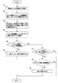
- FIG. 8 is a flow chart showing a flow of control when the depression force of the accelerator pedal 32 is increased more than the base depression force.
- an engine start line is calculated from the SOC of the battery 9 and the vehicle speed, and a first accelerator opening degree is calculated from the engine start line.
- the second accelerator opening degree is calculated from the accelerator opening degree capable of traveling on a flat road at constant speed for each vehicle speed calculated in advance.
- the larger one of the first accelerator opening and the second accelerator opening is used as the accelerator opening threshold.
- step S6 the depression force of the accelerator pedal 32 is increased more than the base depression force.
- the first accelerator opening degree is a value obtained by subtracting a predetermined accelerator opening degree ⁇ from the accelerator opening degree on the engine starting line, but the accelerator opening degree on the engine starting line is the same It is also possible to set the first accelerator opening degree. That is, it is also possible to set the engine start line to the first accelerator opening degree.
- the hybrid vehicle of the embodiment described above is configured to transmit the driving force of both the engine 1 and the motor generator 2 to the wheels, but the present invention is not only applied to such hybrid vehicles, for example, The present invention is applicable to various hybrid vehicles such as a hybrid vehicle configured to use an engine only for power generation, and a hybrid vehicle configured to distribute power from the engine to a generator and a motor by a power split mechanism.
- the automatic transmission 3 is used as the transmission, but it is also possible to use a continuously variable transmission in which the gear ratio changes continuously, instead of the automatic transmission 3.
- a continuously variable transmission it is possible to obtain a transmission ratio as a ratio of rotational speeds on the input shaft side and the output shaft side.
- the engine start line and the engine stop line are changed according to the SOC of the battery 9, but the temperature of the battery 9, the deterioration state of the battery 9, or an operation mode such as a sport running mode It may be changed accordingly.
Abstract
Priority Applications (7)
| Application Number | Priority Date | Filing Date | Title |
|---|---|---|---|
| CN201180025688.3A CN102905927B (zh) | 2010-05-25 | 2011-04-27 | 混合动力车辆的加速器踏板踏力控制装置 |
| MX2012013367A MX2012013367A (es) | 2010-05-25 | 2011-04-27 | Dispositivo de control de accionamiento del pedal del acelerador en vehiculos hibridos. |
| KR1020127030745A KR101420959B1 (ko) | 2010-05-25 | 2011-04-27 | 하이브리드 차량의 액셀러레이터 페달 답력 제어 장치 |
| BR112012030026A BR112012030026A2 (pt) | 2010-05-25 | 2011-04-27 | dispositivo de controle de pressão no pedal do acelerador de véiculo híbrido |
| RU2012156160/11A RU2527652C2 (ru) | 2010-05-25 | 2011-04-27 | Устройство управления силой нажатия педали акселератора для гибридного транспортного средства |
| EP11786453.8A EP2578432B1 (fr) | 2010-05-25 | 2011-04-27 | Dispositif de régulation de la force d'appui sur la pédale d'accélérateur d'un véhicule hybride |
| US13/699,174 US8620566B2 (en) | 2010-05-25 | 2011-04-27 | Hybrid vehicle accelerator pedal depressing force control device |
Applications Claiming Priority (2)
| Application Number | Priority Date | Filing Date | Title |
|---|---|---|---|
| JP2010-118920 | 2010-05-25 | ||
| JP2010118920A JP5471829B2 (ja) | 2010-05-25 | 2010-05-25 | ハイブリッド車両のアクセルペダル踏力制御装置 |
Publications (1)
| Publication Number | Publication Date |
|---|---|
| WO2011148753A1 true WO2011148753A1 (fr) | 2011-12-01 |
Family
ID=45003745
Family Applications (1)
| Application Number | Title | Priority Date | Filing Date |
|---|---|---|---|
| PCT/JP2011/060305 WO2011148753A1 (fr) | 2010-05-25 | 2011-04-27 | Dispositif de régulation de la force d'appui sur la pédale d'accélérateur d'un véhicule hybride |
Country Status (9)
| Country | Link |
|---|---|
| US (1) | US8620566B2 (fr) |
| EP (1) | EP2578432B1 (fr) |
| JP (1) | JP5471829B2 (fr) |
| KR (1) | KR101420959B1 (fr) |
| CN (1) | CN102905927B (fr) |
| BR (1) | BR112012030026A2 (fr) |
| MX (1) | MX2012013367A (fr) |
| RU (1) | RU2527652C2 (fr) |
| WO (1) | WO2011148753A1 (fr) |
Cited By (2)
| Publication number | Priority date | Publication date | Assignee | Title |
|---|---|---|---|---|
| WO2014080468A1 (fr) * | 2012-11-21 | 2014-05-30 | 本田技研工業株式会社 | Dispositif de commande de force antagoniste de pédale d'accélérateur et véhicule |
| US20160221437A1 (en) * | 2014-08-29 | 2016-08-04 | Mazda Motor Corporation | Vehicle accelerator pedal reaction force control device |
Families Citing this family (13)
| Publication number | Priority date | Publication date | Assignee | Title |
|---|---|---|---|---|
| JP5381321B2 (ja) * | 2008-07-31 | 2014-01-08 | 日産自動車株式会社 | アクセルペダル踏力制御装置 |
| US20120047087A1 (en) * | 2009-03-25 | 2012-02-23 | Waldeck Technology Llc | Smart encounters |
| KR101406533B1 (ko) * | 2013-04-16 | 2014-06-12 | 기아자동차주식회사 | 가속페달 장치의 답력 능동 조절방법 |
| KR101406654B1 (ko) * | 2013-04-23 | 2014-06-11 | 기아자동차주식회사 | 가속페달 장치의 답력 능동 조절방법 |
| JP2015048052A (ja) * | 2013-09-04 | 2015-03-16 | トヨタ自動車株式会社 | ペダル装置の取付構造 |
| US9162674B2 (en) | 2013-10-24 | 2015-10-20 | Ford Global Technologies, Llc | Dynamic mapping of pedal position to wheel output demand in a hybrid vehicle |
| WO2015063894A1 (fr) | 2013-10-30 | 2015-05-07 | 本田技研工業株式会社 | Dispositif de commande de force de réaction de pédale |
| GB2523589B (en) * | 2014-02-28 | 2020-04-22 | Bentley Motors Ltd | Hybrid drive system |
| US9189009B2 (en) | 2014-04-01 | 2015-11-17 | Atieva, Inc. | Accelerator pedal feedback system |
| FR3070945B1 (fr) * | 2017-09-08 | 2019-09-13 | Psa Automobiles Sa | Controle de fourniture d’un couple complementaire par une machine motrice non-thermique d’un vehicule hybride en fonction du potentiel d’acceleration |
| JP6521491B1 (ja) * | 2017-12-01 | 2019-05-29 | マツダ株式会社 | 車両の制御装置 |
| RU2681805C1 (ru) * | 2018-04-10 | 2019-03-12 | Сергей Николаевич Низов | Узел акселератора для двигателя внутреннего сгорания с турбонаддувом |
| JP7447720B2 (ja) | 2020-07-20 | 2024-03-12 | 日産自動車株式会社 | エンジン制御方法、及びエンジン制御装置 |
Citations (4)
| Publication number | Priority date | Publication date | Assignee | Title |
|---|---|---|---|---|
| JP2005132225A (ja) * | 2003-10-30 | 2005-05-26 | Nissan Motor Co Ltd | アクセルペダル踏力制御装置 |
| JP2006180626A (ja) | 2004-12-22 | 2006-07-06 | Toyota Motor Corp | ハイブリッド車両の制御装置 |
| JP2007182196A (ja) * | 2006-01-10 | 2007-07-19 | Toyota Motor Corp | 車両用運転補助装置 |
| JP2007261399A (ja) * | 2006-03-28 | 2007-10-11 | Toyota Motor Corp | ハイブリッド車およびその制御方法 |
Family Cites Families (8)
| Publication number | Priority date | Publication date | Assignee | Title |
|---|---|---|---|---|
| SU142540A1 (ru) * | 1958-08-12 | 1960-11-30 | В.К. Зорин | Устройство, облегчающее управление автомобилем |
| SU1244653A1 (ru) * | 1983-06-06 | 1986-07-15 | Опытно-Механический Завод Главленстройматериалов | Устройство управлени исполнительным органом |
| US7490685B2 (en) * | 2002-09-13 | 2009-02-17 | Honda Giken Kogyo Kabushiki Kaisha | Hybrid vehicle |
| US7053566B2 (en) * | 2003-10-15 | 2006-05-30 | Nissan Motor Co., Ltd. | Drive train for hybrid electric vehicle |
| JP4135107B2 (ja) * | 2004-11-04 | 2008-08-20 | アイシン・エィ・ダブリュ株式会社 | ハイブリッド車用駆動装置及びその制御方法 |
| DE102008000577A1 (de) * | 2008-03-10 | 2009-09-17 | Robert Bosch Gmbh | Verfahren und Vorrichtung zum Betreiben eines Fahrzeuges mit Hybridantrieb |
| JP5381321B2 (ja) * | 2008-07-31 | 2014-01-08 | 日産自動車株式会社 | アクセルペダル踏力制御装置 |
| JP4553057B2 (ja) * | 2008-07-31 | 2010-09-29 | 日産自動車株式会社 | アクセルペダル踏力制御装置および方法 |
-
2010
- 2010-05-25 JP JP2010118920A patent/JP5471829B2/ja active Active
-
2011
- 2011-04-27 MX MX2012013367A patent/MX2012013367A/es active IP Right Grant
- 2011-04-27 WO PCT/JP2011/060305 patent/WO2011148753A1/fr active Application Filing
- 2011-04-27 CN CN201180025688.3A patent/CN102905927B/zh active Active
- 2011-04-27 BR BR112012030026A patent/BR112012030026A2/pt not_active IP Right Cessation
- 2011-04-27 US US13/699,174 patent/US8620566B2/en active Active
- 2011-04-27 RU RU2012156160/11A patent/RU2527652C2/ru not_active IP Right Cessation
- 2011-04-27 KR KR1020127030745A patent/KR101420959B1/ko not_active IP Right Cessation
- 2011-04-27 EP EP11786453.8A patent/EP2578432B1/fr active Active
Patent Citations (4)
| Publication number | Priority date | Publication date | Assignee | Title |
|---|---|---|---|---|
| JP2005132225A (ja) * | 2003-10-30 | 2005-05-26 | Nissan Motor Co Ltd | アクセルペダル踏力制御装置 |
| JP2006180626A (ja) | 2004-12-22 | 2006-07-06 | Toyota Motor Corp | ハイブリッド車両の制御装置 |
| JP2007182196A (ja) * | 2006-01-10 | 2007-07-19 | Toyota Motor Corp | 車両用運転補助装置 |
| JP2007261399A (ja) * | 2006-03-28 | 2007-10-11 | Toyota Motor Corp | ハイブリッド車およびその制御方法 |
Cited By (6)
| Publication number | Priority date | Publication date | Assignee | Title |
|---|---|---|---|---|
| WO2014080468A1 (fr) * | 2012-11-21 | 2014-05-30 | 本田技研工業株式会社 | Dispositif de commande de force antagoniste de pédale d'accélérateur et véhicule |
| JP5843412B2 (ja) * | 2012-11-21 | 2016-01-13 | 本田技研工業株式会社 | アクセルペダル反力制御装置及び車両 |
| US9365112B2 (en) | 2012-11-21 | 2016-06-14 | Honda Motor Co., Ltd. | Accelerator-pedal-counterforce control device and vehicle |
| DE112012007156B4 (de) | 2012-11-21 | 2022-02-10 | Honda Motor Co., Ltd. | Gaspedalgegenkraft-Steuerungsvorrichtung und Fahrzeug |
| US20160221437A1 (en) * | 2014-08-29 | 2016-08-04 | Mazda Motor Corporation | Vehicle accelerator pedal reaction force control device |
| US9908409B2 (en) * | 2014-08-29 | 2018-03-06 | Mazda Motor Corporation | Vehicle accelerator pedal reaction force control device |
Also Published As
| Publication number | Publication date |
|---|---|
| MX2012013367A (es) | 2013-01-24 |
| JP5471829B2 (ja) | 2014-04-16 |
| EP2578432B1 (fr) | 2019-06-12 |
| CN102905927B (zh) | 2015-09-30 |
| US20130066508A1 (en) | 2013-03-14 |
| EP2578432A1 (fr) | 2013-04-10 |
| EP2578432A4 (fr) | 2018-03-21 |
| US8620566B2 (en) | 2013-12-31 |
| KR101420959B1 (ko) | 2014-07-17 |
| RU2527652C2 (ru) | 2014-09-10 |
| RU2012156160A (ru) | 2014-06-27 |
| CN102905927A (zh) | 2013-01-30 |
| BR112012030026A2 (pt) | 2016-08-02 |
| KR20130004521A (ko) | 2013-01-10 |
| JP2011245919A (ja) | 2011-12-08 |
Similar Documents
| Publication | Publication Date | Title |
|---|---|---|
| WO2011148753A1 (fr) | Dispositif de régulation de la force d'appui sur la pédale d'accélérateur d'un véhicule hybride | |
| US7498757B2 (en) | Control device for a hybrid electric vehicle | |
| JP5045431B2 (ja) | ハイブリッド車両のエンジン始動制御装置 | |
| JP5832736B2 (ja) | ハイブリッド車両のエンジン始動制御装置 | |
| US9540004B2 (en) | Vehicle control system | |
| US9440653B2 (en) | Drive control device for vehicle | |
| US20140136039A1 (en) | Control device for hybrid vehicle | |
| WO2012056855A1 (fr) | Dispositif de commande pour véhicule hybride | |
| JP5251495B2 (ja) | ハイブリッド車両の駆動制御装置および駆動制御方法 | |
| JP2008195143A (ja) | ハイブリッド車両の協調回生制動制御装置 | |
| JP5462057B2 (ja) | 車両の動力伝達制御装置 | |
| JP2006137332A (ja) | ハイブリッド車用駆動装置及びその制御方法 | |
| JP3702897B2 (ja) | ハイブリッド車両の制御装置 | |
| JP5715848B2 (ja) | 車両の動力伝達制御装置 | |
| JP2004251452A (ja) | ハイブリッド車両の制御装置 | |
| JP5803626B2 (ja) | 車両の制御装置 | |
| KR101063218B1 (ko) | 하이브리드 차량용 오일펌프 및 클러치간의 유압 제어 장치및 방법 | |
| JP2012091620A (ja) | ハイブリッド車両のエンジン始動制御装置 | |
| JP5223903B2 (ja) | ハイブリッド車両のアイドル制御装置 | |
| JP2012086710A (ja) | ハイブリッド車両のアイドル制御装置 | |
| JP2013067265A (ja) | 車両の制御装置 | |
| JP2023169919A (ja) | 車両の制御装置 | |
| JP2022155289A (ja) | 車両用駆動装置 | |
| WO2015019804A1 (fr) | Système de régénération de volant d'inertie, et son procédé de commande | |
| JP2007261494A (ja) | 車両用制御装置 |
Legal Events
| Date | Code | Title | Description |
|---|---|---|---|
| WWE | Wipo information: entry into national phase |
Ref document number: 201180025688.3 Country of ref document: CN |
|
| 121 | Ep: the epo has been informed by wipo that ep was designated in this application |
Ref document number: 11786453 Country of ref document: EP Kind code of ref document: A1 |
|
| WWE | Wipo information: entry into national phase |
Ref document number: MX/A/2012/013367 Country of ref document: MX |
|
| WWE | Wipo information: entry into national phase |
Ref document number: 13699174 Country of ref document: US |
|
| ENP | Entry into the national phase |
Ref document number: 20127030745 Country of ref document: KR Kind code of ref document: A |
|
| NENP | Non-entry into the national phase |
Ref country code: DE |
|
| WWE | Wipo information: entry into national phase |
Ref document number: 4040/KOLNP/2012 Country of ref document: IN |
|
| ENP | Entry into the national phase |
Ref document number: 2012156160 Country of ref document: RU Kind code of ref document: A |
|
| WWE | Wipo information: entry into national phase |
Ref document number: 2011786453 Country of ref document: EP |
|
| REG | Reference to national code |
Ref country code: BR Ref legal event code: B01A Ref document number: 112012030026 Country of ref document: BR |
|
| ENP | Entry into the national phase |
Ref document number: 112012030026 Country of ref document: BR Kind code of ref document: A2 Effective date: 20121126 |