WO2011135889A1 - 半導体発光素子、半導体発光素子の保護膜及びその作製方法 - Google Patents
半導体発光素子、半導体発光素子の保護膜及びその作製方法 Download PDFInfo
- Publication number
- WO2011135889A1 WO2011135889A1 PCT/JP2011/052814 JP2011052814W WO2011135889A1 WO 2011135889 A1 WO2011135889 A1 WO 2011135889A1 JP 2011052814 W JP2011052814 W JP 2011052814W WO 2011135889 A1 WO2011135889 A1 WO 2011135889A1
- Authority
- WO
- WIPO (PCT)
- Prior art keywords
- film
- protective film
- semiconductor light
- sin
- emitting element
- Prior art date
- Legal status (The legal status is an assumption and is not a legal conclusion. Google has not performed a legal analysis and makes no representation as to the accuracy of the status listed.)
- Ceased
Links
Images

Classifications
-
- H—ELECTRICITY
- H10—SEMICONDUCTOR DEVICES; ELECTRIC SOLID-STATE DEVICES NOT OTHERWISE PROVIDED FOR
- H10H—INORGANIC LIGHT-EMITTING SEMICONDUCTOR DEVICES HAVING POTENTIAL BARRIERS
- H10H20/00—Individual inorganic light-emitting semiconductor devices having potential barriers, e.g. light-emitting diodes [LED]
- H10H20/80—Constructional details
- H10H20/84—Coatings, e.g. passivation layers or antireflective coatings
-
- H—ELECTRICITY
- H01—ELECTRIC ELEMENTS
- H01L—SEMICONDUCTOR DEVICES NOT COVERED BY CLASS H10
- H01L2224/00—Indexing scheme for arrangements for connecting or disconnecting semiconductor or solid-state bodies and methods related thereto as covered by H01L24/00
- H01L2224/01—Means for bonding being attached to, or being formed on, the surface to be connected, e.g. chip-to-package, die-attach, "first-level" interconnects; Manufacturing methods related thereto
- H01L2224/02—Bonding areas; Manufacturing methods related thereto
- H01L2224/0212—Auxiliary members for bonding areas, e.g. spacers
- H01L2224/02122—Auxiliary members for bonding areas, e.g. spacers being formed on the semiconductor or solid-state body
- H01L2224/02163—Auxiliary members for bonding areas, e.g. spacers being formed on the semiconductor or solid-state body on the bonding area
- H01L2224/02165—Reinforcing structures
- H01L2224/02166—Collar structures
-
- H—ELECTRICITY
- H01—ELECTRIC ELEMENTS
- H01L—SEMICONDUCTOR DEVICES NOT COVERED BY CLASS H10
- H01L2224/00—Indexing scheme for arrangements for connecting or disconnecting semiconductor or solid-state bodies and methods related thereto as covered by H01L24/00
- H01L2224/01—Means for bonding being attached to, or being formed on, the surface to be connected, e.g. chip-to-package, die-attach, "first-level" interconnects; Manufacturing methods related thereto
- H01L2224/42—Wire connectors; Manufacturing methods related thereto
- H01L2224/47—Structure, shape, material or disposition of the wire connectors after the connecting process
- H01L2224/48—Structure, shape, material or disposition of the wire connectors after the connecting process of an individual wire connector
- H01L2224/484—Connecting portions
- H01L2224/48463—Connecting portions the connecting portion on the bonding area of the semiconductor or solid-state body being a ball bond
-
- H—ELECTRICITY
- H01—ELECTRIC ELEMENTS
- H01L—SEMICONDUCTOR DEVICES NOT COVERED BY CLASS H10
- H01L2224/00—Indexing scheme for arrangements for connecting or disconnecting semiconductor or solid-state bodies and methods related thereto as covered by H01L24/00
- H01L2224/01—Means for bonding being attached to, or being formed on, the surface to be connected, e.g. chip-to-package, die-attach, "first-level" interconnects; Manufacturing methods related thereto
- H01L2224/42—Wire connectors; Manufacturing methods related thereto
- H01L2224/47—Structure, shape, material or disposition of the wire connectors after the connecting process
- H01L2224/49—Structure, shape, material or disposition of the wire connectors after the connecting process of a plurality of wire connectors
- H01L2224/491—Disposition
- H01L2224/49105—Connecting at different heights
- H01L2224/49107—Connecting at different heights on the semiconductor or solid-state body
-
- H—ELECTRICITY
- H10—SEMICONDUCTOR DEVICES; ELECTRIC SOLID-STATE DEVICES NOT OTHERWISE PROVIDED FOR
- H10H—INORGANIC LIGHT-EMITTING SEMICONDUCTOR DEVICES HAVING POTENTIAL BARRIERS
- H10H20/00—Individual inorganic light-emitting semiconductor devices having potential barriers, e.g. light-emitting diodes [LED]
- H10H20/01—Manufacture or treatment
- H10H20/034—Manufacture or treatment of coatings
Definitions
- the present invention relates to a semiconductor light emitting device, a protective film for the semiconductor light emitting device, and a method for manufacturing the same.
- a white LED Light Emitting Diode
- the protective film Since migration accelerates when Ag reacts with moisture, migration can be suppressed by using a protective film that protects Ag from moisture in the LED element, which is effective in improving the reliability of high-power elements.
- the protective film is required to have high light transmittance so that light generated in the element can be efficiently extracted outside the element.
- FIG. 8 the LED element structure of Patent Document 1 is shown in FIG.
- reference numeral 61 is a substrate
- 62 is an n-type semiconductor layer
- 63 is an active layer
- 64 is a p-type semiconductor layer
- 65 is a p-electrode
- 66 is a p-pad
- 67 is an n-electrode
- 68 is an n-pad
- 71 is a SiN film
- 72 is a SiO film.
- the p electrode 65 has a multilayer structure made of Ag / Ni / Pt.
- the arrow in a figure has shown the mode of the transmitted light.
- a highly waterproof SiN film 71 is used only on the periphery of the p-electrode 65 as a protective film, and then an SiO film 72 is formed on the entire surface.
- the SiN film 71 is formed only at the periphery of the p-electrode 65, a process of removing a part of the SiN 71 film on the whole is required before the SiO film 72 is formed, and the film formation cost is reduced. Get higher.
- Ag in the p-electrode 65 diffuses to the side surface of the semiconductor, migration is likely to proceed because the SiO film 72 is not waterproof.
- the light transmittance of the SiN film 71 is lower than that of the SiO film 72. Therefore, the transmittance is reduced around the p-electrode 65, and the light extraction efficiency to the outside is reduced.
- a highly waterproof SiN film 81 is used for the entire element as a protective film.
- the SiN film 81 having a low transmittance since the entire element is covered with the SiN film 81 having a low transmittance, the light extraction efficiency from the element to the outside is lowered. Further, since the SiN film 81 generally has a lower withstand voltage than the SiO film, it is necessary to increase the film thickness in order to ensure insulation, and it takes time to form the film and the film formation cost increases.
- the present invention has been made in view of the above problems, and an object thereof is to provide a semiconductor light emitting device that satisfies all of high migration prevention, high transmittance, and low film formation cost, a protective film for the semiconductor light emitting device, and a method for manufacturing the same. To do.
- the protective film of the semiconductor light emitting device according to the first invention for solving the above-described problems is, In a semiconductor light emitting device having a plurality of semiconductor layers formed on a substrate and a plurality of electrode portions to be electrodes of the plurality of semiconductor layers, a protective film for protecting the semiconductor light emitting device, As the protective film, a first protective film that covers the periphery of the plurality of semiconductor layers and the plurality of electrode portions is provided, The first protective film is silicon nitride having a Si—H bond content of less than 1.0 ⁇ 10 21 [pieces / cm 3 ] in the film.
- the protective film of the semiconductor light emitting element according to the second invention for solving the above-described problems is In the protective film of the semiconductor light emitting element according to the first invention, Furthermore, while providing a second protective film covering the periphery of the first protective film, The first protective film has a thickness of 10 nm or more, The second protective film is made of silicon oxide.
- a protective film of a semiconductor light emitting element according to a third invention for solving the above-described problems is In the protective film of the semiconductor light emitting element according to the second invention, Furthermore, while providing a third protective film covering the periphery of the second protective film, Similar to the first protective film, the third protective film is silicon nitride having a Si—H bond content of less than 1.0 ⁇ 10 21 [pieces / cm 3 ] in the film, and the film thickness is It is characterized by being 10 nm or more.
- a protective film of a semiconductor light emitting element according to a fourth invention for solving the above-described problems is
- the second protective film is made of silicon oxide having a Si—OH bond amount of 1.3 ⁇ 10 21 [pieces / cm 3 ] or less in the film, and the film thickness of the first protective film in this case is It is characterized by being 5 nm or more.
- a protective film of a semiconductor light emitting element according to a fifth invention for solving the above-mentioned problems is as follows.
- At least one of the plurality of electrode portions is made of a metal containing silver.
- a semiconductor light emitting device for solving the above-described problems is as follows.
- a protective film for a semiconductor light emitting device according to any one of the first to fifth inventions is used.
- a manufacturing method of a protective film of a semiconductor light emitting element according to a seventh invention for solving the above-described problem is as follows.
- a method for producing a protective film for protecting the semiconductor light emitting device As the protective film, a first protective film covering the periphery of the plurality of semiconductor layers and the plurality of electrode portions is provided, and the amount of Si—H bonds in the film is 1.0 ⁇ 10 21 [pieces / cm 3 ]. It is characterized by being formed from less than silicon nitride.
- a manufacturing method of a protective film of a semiconductor light emitting element according to an eighth invention for solving the above-described problems is as follows.
- the first protective film has a thickness of 10 nm or more, Further, a second protective film covering the periphery of the first protective film is provided, and is formed from silicon oxide.
- a manufacturing method of a protective film of a semiconductor light emitting element according to a ninth invention for solving the above-described problems is as follows.
- a third protective film is provided to cover the periphery of the second protective film, and the Si—H bond amount in the film is 1.0 ⁇ 10 21 [pieces / cm 3 , as in the first protective film. ], And the film thickness is 10 nm or more.
- the second protective film is formed of silicon oxide having a Si—OH bond amount of 1.3 ⁇ 10 21 [pieces / cm 3 ] or less in the film, and the film thickness of the first protective film in this case Is 5 nm or more.
- a manufacturing method of a protective film of a semiconductor light emitting element according to an eleventh invention for solving the above-described problem is In the method for manufacturing a semiconductor light emitting element according to any one of the seventh to tenth inventions, At least one of the plurality of electrode portions is made of a metal containing silver.
- a semiconductor light emitting device can satisfy all of high migration prevention, high transmittance, and low film formation cost, and a high luminance structure is realized.
- FIG. 2 It is sectional drawing which shows the element structure as an example (Example 1) of the embodiment of the semiconductor light-emitting device which concerns on this invention. It is a block diagram of the plasma processing apparatus which forms the SiN film
- membrane of the semiconductor light-emitting device shown in FIG. 2 is a graph showing the relationship between the transmittance of the SiN film of the semiconductor light emitting device shown in FIG. 1 and the amount of hydrogen in the film. It is sectional drawing which shows the element structure as an example (Example 2) of the embodiment of the semiconductor light-emitting device which concerns on this invention. 5 is a graph showing the relationship between waterproofness and film thickness in the SiN film of the semiconductor light emitting device shown in FIG. 4 and a conventional SiN film.
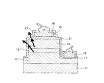
- substrate 12 n-type semiconductor layer 13 active layer 14 p-type semiconductor layer 15 p-electrode (electrode part) 16 p pad (electrode part) 17 n electrode (electrode part) 18 n pad (electrode part) 21, 31, 41, 51 SiN film (first protective film) 32, 42, 52 SiO film (second protective film) 43, 53 SiN film (third protective film)
- FIG. 1 is a cross-sectional view showing the element structure of the LED of this example. Moreover, the arrow in a figure has shown the mode of the transmitted light.
- the LED of this embodiment includes an n-type semiconductor layer 12 made of n-type GaN, an active layer 13 made of a multiple quantum well structure in which GaN and InGaN are alternately stacked, and a p-type made of p-type GaN on a substrate 11 made of sapphire.
- This is an element structure of a semiconductor layer in which type semiconductor layers 14 are sequentially stacked.
- the n-type semiconductor layer 12 and the p-type semiconductor layer 14 have a structure including an n-type contact layer and a p-type contact layer, respectively.
- a part of the stacked p-type semiconductor layer 14, active layer 13, and n-type semiconductor layer 12 is removed by etching to expose the n-type contact layer of the n-type semiconductor layer 12, and the exposed portion.
- W / Pt is sequentially stacked from the semiconductor layer side to form the n-electrode 17.
- a p-electrode 15 is formed by sequentially stacking Ag / Ni / Pt from the semiconductor layer side.
- a p-pad 16 made of Au is formed on the p-electrode 15, and an n-pad 18 made of Au is formed on the n-electrode 17.
- the p electrode 15 and the p pad 16, and the n electrode 17 and the n pad 18 are used as electrode portions for the stacked semiconductor layers, respectively.
- the semiconductor layer n-type semiconductor layer 12, active layer 13 and p-type semiconductor layer 14
- electrode portion p-electrode 15 and p-type semiconductor layer 14, except for the openings for bumps in the p-pad 16 and n-pad 18.
- a SiN film 21 (first protective film) is laminated so as to cover the periphery of the p pad 16, the n electrode 17 and the n pad 18).
- the SiN film 21 is made of SiN having insulating properties and high transmittance, and a protective film is formed by this one layer. As described above, the SiN film 21 protects not only the p electrode 15 containing Ag but also the entire element.
- a protective film made of SiN usually has a high waterproof property, but has a problem of low transmittance and poor dielectric strength.
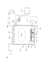
- the SiN film 21 is formed by the plasma CVD apparatus using the high-density plasma shown in FIG. 2, and thereby, the high transmittance equivalent to that of the SiO film while being the SiN film.
- the film quality can be
- the plasma CVD apparatus 100 includes a vacuum vessel 101 that maintains a high degree of vacuum.
- the vacuum vessel 101 includes a cylindrical vessel 102 and a ceiling plate 103, and a ceiling plate 103 is attached to the upper portion of the cylindrical vessel 102 to form a space sealed from the outside air.
- the vacuum vessel 104 is provided with a vacuum device 104 that evacuates the inside of the vacuum vessel 101.
- An RF antenna 105 that generates plasma is installed on the top of the ceiling plate 103.
- An RF power source 107 that is a high frequency power source is connected to the RF antenna 105 via a matching unit 106. That is, the RF power supplied from the RF power source 107 is supplied to the plasma by the RF antenna 105.
- a gas supply pipe 108 for supplying a raw material gas or an inert gas, which is a raw material for a film to be formed, into the vacuum container 101 is installed on the upper side wall of the cylindrical container 102.
- the gas supply pipe 108 is provided with a gas supply amount controller for controlling the supply amount of the source gas and the inert gas.
- SiH 4 , N 2 or the like is supplied as a source gas
- Ar or the like is supplied as an inert gas.
- plasma such as SiH 4 , N 2, and Ar is generated above the inside of the vacuum vessel 101.
- a substrate support 110 for holding a substrate 109 that is a film formation target is installed below the cylindrical container 102.
- the substrate support 110 includes a substrate holding part 111 that holds the substrate 109 and a support shaft 112 that supports the substrate holding part 111.
- a heater 113 for heating is installed inside the substrate holder 111, and the temperature of the heater 113 is adjusted by a heater control device 114. Thereby, the temperature of the substrate 109 during the plasma processing can be controlled to 300 ° C., for example.
- the RF power from the RF power source 107, the pressure from the vacuum device 104, the substrate temperature from the heater control device 114, the gas supply amount from the gas supply amount controller, and the vertical drive mechanism are used.
- a main control device 119 capable of controlling the substrate position is installed. 2 represents a signal line for transmitting a control signal from the main controller 119 to the RF power source 107, the vacuum device 104, the heater controller 114, and the gas supply amount controller.
- the main controller 119 controls the RF power, pressure, film formation temperature, gas supply amount, and substrate position, so that the SiN film can be formed in this embodiment.
- the substrate 109 is disposed at a position away from the plasma center, the film quality having the same high transmittance as that of the SiO film can be obtained although it is a SiN film.
- the SiN film 21 in this embodiment is a SiN film, but has a high transmittance equivalent to that of the SiO film.
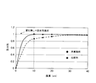
- SiN formed by a general plasma CVD apparatus is shown as a comparative example.
- the film thickness was set to 400 nm having the minimum strength as a protective film, and evaluation was performed at a wavelength of 350 nm.
- the amount of hydrogen in the SiN film is confirmed by IR analysis (infrared analysis, for example, FTIR), as shown in FIG. 3, the amount of Si—H bonds (of Si—H bonds generated near 2140 cm ⁇ 1 )
- IR analysis infrared analysis, for example, FTIR
- the amount of Si—H bonds is decreased, a film having a high transmittance is obtained.
- the Si—H bond amount is 2.0 ⁇ 10 22 [pieces / cm 3 ] or more even under the best process conditions.
- the transmittance remains at about 88%.
- the Si—H bond amount can be made smaller than 2.0 ⁇ 10 22 [pieces / cm 3 ], and the transmittance can be increased.
- the Si—H bond amount is less than 1.0 ⁇ 10 21 [pieces / cm 3 ]
- the transmittance is also achieved to be 98% or more.
- the extinction coefficient k of the film itself is 0.005 or less. As a result, it is considered that a high transmittance is obtained.
- the film thickness of the SiN film 21 is a film thickness that can physically protect the element, that is, a film thickness that does not damage the semiconductor layer of the element. Specifically, it is used in general LEDs. 400 to 1000 nm. In such a range of film thickness, the SiN film 21 has a sufficient waterproof property as shown in FIG. 5 to be described later, and also has the characteristics that the withstand voltage is high and the transmittance is also high as described above. Have.
- the entire element is covered with the SiN film 21 except for a very small part (pad opening), the penetration of moisture into the inside of the element side wall is prevented, and the p electrode 15 The migration of Ag therein can be suppressed, and high migration prevention can be obtained. Further, since the dielectric strength of the film itself is high, it is not necessary to increase the film thickness of the SiN film 21 as in the prior art, and the etching is unnecessary, so that the film formation cost can be suppressed.
- Example 2 Compared with the above-described Conventional Example 1 and Conventional Example 2 in terms of migration prevention, transmittance, film formation cost, and high brightness structure, the results are shown in Table 1. In Table 1, Example 2, Example 3, and Example 4 described later are also shown.
- the migration prevention property in this example is higher than that of Conventional Example 1 and equivalent to that of Conventional Example 2 because the entire element is covered with SiN film 21, and the reliability of the element is improved. .
- the transmittance in the present example is 99.6% when compared with the thickness of 500 nm and the light wavelength of 350 nm when compared with each other. This is higher than Conventional Example 2 and is substantially equivalent to Conventional Example 1 (when the transmittance near the p electrode is also taken into consideration), and the light extraction efficiency is improved.
- the film formation cost in this example is higher than the normal SiN film, and the thickness of the entire protective film can be reduced. Therefore, the conventional example 1 that requires an etching process and the conventional example 2 that increases the film thickness, It is low.
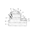
- FIG. 4 is a cross-sectional view showing the element structure of the LED of this example.
- the same reference numerals are given to the same components as those shown in the first embodiment (see FIG. 1), and duplicate descriptions are omitted.
- the arrow in a figure has shown the mode of the transmitted light.
- the element structure of the semiconductor layer has the same configuration as the LED shown in Example 1 (see FIG. 1). Further, as in the first embodiment, a protective film is formed so as to cover the periphery of the semiconductor layer and the electrode portion except for the openings for the bumps in the p pad 16 and the n pad 18. The structure of the film is different from that of Example 1.
- an SiN film 31 (first protective film) made of SiN having insulating properties and high transmittance
- an SiO film 32 (second protective film) made of SiO having insulating properties. )
- a protective film having a two-layer structure in which the first layer is the SiN film 31 and the second layer is the SiO film 32 is formed.
- SiN film 31 is formed by the plasma CVD apparatus shown in FIG.
- the SiO film 32 may be the plasma CVD apparatus shown in FIG. 2, but may be a normal plasma CVD method (apparatus), and particularly, a plasma CVD method (apparatus) using high-density plasma is suitable. If a similar SiO film can be formed, other methods such as a sputtering method (apparatus) and a vacuum deposition method (apparatus) can be used.
- a protective film made of SiN usually has a high waterproof property, but has a problem of low transmittance and poor dielectric strength.
- the SiN film 31 has a thickness that can increase the transmittance and maintain the waterproof property as described with reference to FIG. Further, a SiO film 32 having a high transmittance and a high withstand voltage is laminated on the outside of the SiN film 31 although the waterproof property is inferior.
- the relationship between the waterproof property and the film thickness in the SiN film 31 will be described with reference to the graph of FIG.
- FIG. 5 as a comparative example, a graph of waterproofness and film thickness in SiN formed by a general plasma CVD apparatus is shown with dotted lines.
- the waterproof property in FIG. 5 means that as a sample, a SiN film to be evaluated and a SiO film with a large amount of moisture in the film are sequentially formed on a cobalt-iron film. By measuring the degradation, the waterproof property of the SiN film to be evaluated is evaluated.
- the waterproofness decreases as the film thickness decreases, but the film thickness of the SiN film is 35 nm or more. In this case, it can be seen that the waterproof property is good.
- the waterproof property decreases as the film thickness decreases.
- the film thickness of the SiN film is 10 nm or more, the waterproof property is reduced. It turns out that it is favorable.
- good waterproofness could not be obtained unless the thickness was 35 nm or more, but in this example, good waterproofness is obtained by setting the thickness of the SiN film 31 to 10 nm or more. be able to. That is, in the SiN film 31, a thickness of 10 nm or more is a film thickness that can maintain waterproofness.
- the total film thickness of the SiO film 32 and the SiN film 31 is set to a film thickness that can physically protect the element, that is, a film thickness that does not damage the semiconductor layer of the element. Specifically, the total film thickness is set to 400 to 1000 nm used in general LEDs.
- the SiN film 31 since the entire element is covered with the SiN film 31 except for a very small part (pad opening), moisture can be prevented from entering the inside of the p-side electrode 15 on the side wall of the element. Ag migration can be suppressed, and high migration prevention can be obtained. Further, since it is not necessary to increase the thickness of the SiN film 31 and the etching is not necessary, the film forming cost can be suppressed.
- the migration preventing property in this example is higher than that of the conventional example 1 because the entire device is covered with the SiN film 31, and the reliability of the device is improved.
- the transmittance in the present example is compared under the conditions of a film thickness of 500 nm and a light wavelength of 350 nm (the film thickness of the SiN film 31 of the present example is 35 nm, the transmittance is 99.9%), and the protective film The overall transmittance is 99.9%.
- This is higher than Conventional Example 2 and substantially the same as Conventional Example 1 (when the transmittance near the p-electrode is also taken into consideration), and is higher than Example 1 and improves the light extraction efficiency.
- the film formation cost in this embodiment is that the dielectric breakdown voltage is high and the entire thickness of the protective film can be reduced by the lamination of the SiO film 32, so that the conventional example 1 in which the etching process is required and the conventional example 2 in which the film thickness is increased. It is lower and is equivalent to the first embodiment.
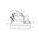
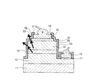
- FIG. 6 is a cross-sectional view showing the element structure of the LED of this example.
- the same components as those shown in the first embodiment (see FIG. 1) are denoted by the same reference numerals, and redundant description is omitted.
- the arrow in a figure has shown the mode of the transmitted light.
- the element structure of the semiconductor layer has the same configuration as the LED shown in Example 1 (see FIG. 1). Further, as in the first embodiment, a protective film is formed so as to cover the periphery of the semiconductor layer and the electrode portion except for the openings for the bumps in the p pad 16 and the n pad 18. The structure of the film is different from that of the first and second embodiments.
- an SiN film 41 (first protective film) made of SiN having insulating properties and high transmittance, and an SiO film 42 (second protective film) made of SiO having insulating properties.
- an SiN film 43 (third protective film) made of SiN having insulating properties and high transmittance are sequentially stacked. That is, a protective film having a three-layer structure in which the SiN film 41 is the first layer, the SiO film 42 is the second layer, and the SiN film 43 is the third layer is formed. In this way, not only the periphery of the p electrode 15 containing Ag but also the periphery of the entire device is protected by the three-layer structure of the SiN film 41, the SiO film 42, and the SiN film 43.
- SiN films 41 and 43 are formed by the plasma CVD apparatus shown in FIG.
- the SiO film 42 may be the plasma CVD apparatus shown in FIG. 2, but may be a normal plasma CVD method (apparatus), and particularly, a plasma CVD method (apparatus) using high-density plasma is suitable. If a similar SiO film can be formed, other methods such as a sputtering method (apparatus) and a vacuum deposition method (apparatus) can be used.
- a protective film made of SiN usually has a high waterproof property, but has a problem of low transmittance and poor dielectric strength.
- the protective film made of SiO is easy to pass water and is easy to hold, so if the film once contains a lot of moisture, it becomes a moisture supply source, and a protective film made of SiN is formed inside it.
- the film thickness is small, there is a problem that water penetrates into the element side through the protective film although it is slight.
- the SiN film 41 is made to have a thickness of 10 nm or more so as to increase the transmittance as described with reference to FIG. 3 and to maintain waterproofness as described with reference to FIG. Further, a SiO film 42 having a high transmittance and a high withstand voltage is laminated on the outside of the SiN film 41, but the transmittance is high and the waterproof property can be maintained outside the SiO film 42.
- a SiN film 43 having a thickness of 10 nm or more is stacked.
- the total film thickness of the SiO film 42 and the SiN film 41 and the SiN film 43 is set to a film thickness that can physically protect the element, that is, a film thickness that does not damage the semiconductor layer of the element. Specifically, the total film thickness is set to 400 to 1000 nm used in general LEDs.
- the SiN film 41 since the entire element is covered with the SiN film 41 except for a very small part (pad opening), moisture can be prevented from entering the inside of the p-side electrode 15 on the side wall of the element. Ag migration can be suppressed, and high migration prevention can be obtained. Further, in this embodiment, since the SiN film 43 is further provided outside the SiO film 42, moisture entering the protective film, in particular, the inside of the SiO film 42 can be reduced. It is possible to reduce the moisture that enters the water. As a result, compared with Example 1 and Example 2, migration prevention property was able to be improved further. Further, it is not necessary to increase the film thickness of the SiN films 41 and 43 as in the prior art, and the etching is unnecessary, so that the film formation cost can be suppressed.
- the migration preventing property in this example is higher than that in the conventional example 1 and higher than that in the example 2, and the reliability of the device is further improved.
- the transmittance in the present example is compared under the conditions of a film thickness of 500 nm and a light wavelength of 350 nm (the film thickness of the SiN films 41 and 43 in this example is 35 nm, and the transmittance is 99.9%).
- the transmittance of the entire membrane is 99.9%.
- This transmittance is higher than that of Conventional Example 2 and is substantially the same as that of Conventional Example 1 (when the transmittance in the vicinity of the p-electrode is also taken into consideration), and is higher than that of Example 1 and equivalent to that of Example 2. Efficiency is improved.
- the thickness of the SiN films 41 and 43 with low transmittance is smaller than the thickness of the entire protective film, and the thickness of the SiO film 42 with high transmittance is thick. This is because a high transmittance can be obtained.
- the film forming cost in this embodiment is slightly higher than that of the second embodiment.
- the protective film as a whole has a high withstand voltage due to the lamination of the SiO film 42, and the protective film. Since the entire thickness can be reduced, it is lower than Conventional Example 1 that requires an etching process and Conventional Example 2 that increases the film thickness.
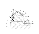
- FIG. 7 is a cross-sectional view showing the element structure of the LED of this example.
- the same components as those shown in the first embodiment (see FIG. 1) are denoted by the same reference numerals, and redundant description is omitted.
- the arrow in a figure has shown the mode of the transmitted light.
- the element structure of the semiconductor layer has the same configuration as the LED shown in Example 1 (see FIG. 1). Further, as in the first embodiment, a protective film is formed so as to cover the periphery of the semiconductor layer and the electrode portion except for the openings for the bumps in the p pad 16 and the n pad 18. The structure of the film is different from that of the first and second embodiments. Furthermore, the film quality of the SiO film is different from that of Example 3.
- an insulating SiN film 51 (first protective film) made of SiN having high transmittance, and an insulating SiO film made of SiO with a small amount of moisture in the film.
- a film 52 (second protective film) and an SiN film 53 (third protective film) made of SiN having insulating properties and high transmittance are sequentially stacked. That is, a protective film having a three-layer structure in which the first layer is a SiN film 51, the second layer is a SiO film 52, and the third layer is a SiN film 53 is formed.
- the periphery of the p electrode 15 containing Ag but also the periphery of the entire element is protected by the three-layer structure of the SiN film 51, the SiO film 52, and the SiN film 53.
- SiN films 51 and 53 are formed by the plasma CVD apparatus shown in FIG.
- the SiO film 52 is formed by a normal plasma CVD method (apparatus), and in particular, a plasma CVD method (apparatus) using high-density plasma, for example, a plasma CVD apparatus as shown in FIG. It is. If a similar SiO film can be formed, other methods such as a sputtering method (apparatus) and a vacuum deposition method (apparatus) can be used.
- a protective film made of SiN usually has a high waterproof property, but has a problem of low transmittance and poor dielectric strength.
- the protective film made of SiO is easy to pass water and is easy to hold, so if the film once contains a lot of moisture, it becomes a moisture supply source, and a protective film made of SiN is formed inside it.
- the film thickness is small, there is a problem that water penetrates into the semiconductor layer side through the protective film although it is slight.
- an SiO film with a small amount of moisture in the film is used as the SiO film 52. That is, as the SiO film, the Si—OH bond amount (obtained from the peak area of the Si—OH bond generated in the vicinity of 3738 cm ⁇ 1 ) is 1.3 ⁇ 10 21 [pieces / cm 3 ] as measured by IR analysis. If the film quality is as follows, the moisture content in the film is sufficiently low even in thermal desorption spectroscopy (TDS) measurement. Table 2 below shows a comparison between the normal SiO film used in Examples 2 and 3 and the low moisture content SiO film used in this example.
- TDS thermal desorption spectroscopy
- the amount of Si—OH bonds and the amount of water in a normal SiO film are 2.6 ⁇ 10 21 [pieces / cm 3 ], whereas in the low-moisture SiO film of this example, both of them are 1 ⁇ 2 It has become the amount.
- the SiN film 43 since the SiN film 43 is provided in the third layer, almost no water enters the SiO film 42 from the outside. However, since the SiO film 42 originally contains a lot of water, The thickness of the first layer SiN film 41 that prevents moisture diffusion to the element side could not be reduced.
- the moisture content in the film of the SiO film in this example is 1 ⁇ 2 that of a normal SiO film, and therefore, the SiN film 51 that prevents moisture diffusion to the element side. 2
- the minimum film thickness of 10 nm that can maintain waterproofness described in FIG. 2 can be reduced to 5 nm, which is a half of the minimum film thickness, thereby obtaining a higher transmittance than in Example 3. be able to.
- a three-layer structure in which a SiO film 52 having a high transmittance and a high withstand voltage is laminated outside the SiN film 51, and a SiN film 53 is laminated outside the SiO film 52.
- the SiN film 51 has a thickness of 5 nm or more as described above because the transmittance is increased and the moisture content in the SiO film 52 is small as described with reference to FIG.
- a SiN film 53 having a thickness of 10 nm or more that has high transmittance and can maintain waterproofness is laminated on the outside of the SiO film 52.
- the total film thickness of the SiN film 51, the SiO film 52, and the SiN film 53 is a film thickness that can physically protect the element, that is, a film thickness that does not damage the semiconductor layer of the element.
- the total film thickness is set to 400 to 1000 nm used in general LEDs.
- the SiN film 51 since the entire element is covered with the SiN film 51 except for a very small part (pad opening), moisture can be prevented from entering the inside of the p-side electrode 15 at the side wall of the element. Ag migration can be suppressed, and high migration prevention can be obtained.
- the thickness of the SiN 51 is thinner than that of the SiN film 41 of the third embodiment.
- the moisture in the SiO film 52 itself is small, sufficiently high migration prevention can be obtained.
- the amount of moisture in the SiO film 52 itself is low, and the SiN film 53 is further provided on the outside thereof, so that moisture entering the protective film, particularly, the inside of the SiO film 52 is reduced. Therefore, moisture entering the element side can be reduced.
- Example 2 it was possible to further improve the migration prevention property as compared with Example 2. Further, it is not necessary to increase the thickness of the SiN films 51 and 53 as in the prior art, and the etching is not required, so that the film formation cost can be suppressed.
- the migration preventing property in this example is higher than that in the conventional example 1 and higher than that in the example 2, and the reliability of the device is further improved.
- the transmittance in the present example is compared under the conditions of a film thickness of 500 nm and a light wavelength of 350 nm (the film thickness of the SiN films 51 and 53 of the present example is 35 nm, and the transmittance is 99.9%), protection.
- the transmittance of the entire membrane is 99.9%.
- This transmittance is higher than Conventional Example 2 and is substantially equivalent to Conventional Example 1 (when the transmittance in the vicinity of the p-electrode is also taken into consideration). Also, it is higher than Example 1 and equivalent to Examples 2 and 3. The light extraction efficiency is improved.
- the SiN films 51 and 53 having low transmittance are thinner than the entire protective film, and the SiO film 52 having high transmittance is thick. This is because a high transmittance can be obtained over the entire protective film.
- the deposition cost in this example is slightly higher than that of Example 2 because the SiN film 53 is further laminated, but is slightly lower than that of Example 3 because the thickness of the SiN film 51 is thin. Since the protective film as a whole has a high withstand voltage and the thickness of the entire protective film can be reduced by the lamination of the SiO film 52, it is lower than Conventional Example 1 that requires an etching process and Conventional Example 2 that increases the film thickness. Yes.
- each semiconductor layer may be a nitride semiconductor composed of group III atoms such as In, Al, and Ga and group V atoms N.
- the active layer 13 is not limited to a multiple quantum well structure, and may be a single quantum well structure or a strained quantum well structure.
- the substrate 11 is not limited to a sapphire substrate, but may be a GaN substrate.
- each semiconductor layer is manufactured by a known manufacturing method such as metal organic chemical vapor deposition (MOVPE: Metal-Organic-Vapor-Phase Epitaxy) or metal-organic chemical vapor deposition (MOCVD: Metal-Organic Chemical-Vapor-Deposition). Can be used.
- MOVPE Metal-Organic-Vapor-Phase Epitaxy
- MOCVD Metal-organic chemical vapor deposition
- the p electrode 15 has a multilayer structure, but may include a metal other than Ni and Pt as long as it contains a metal such as Ag or Cu that may migrate.
- the manufacturing method can use a well-known manufacturing method, for example, sputtering method, a vacuum evaporation method, etc., It forms in a desired pattern by the lift-off method after lamination
- a multilayer structure in which upper and lower layers such as an Ag layer are composed of other metals has been used. Since the entire element is covered, migration of Ag or the like can be sufficiently suppressed without necessarily adopting such a sand structure.
- the p pad 16, the n electrode 17, and the n pad 18 have a single layer structure or a multilayer structure, and the manufacturing method is the same as the p electrode 15, for example, a known manufacturing method such as sputtering or vacuum deposition. For example, a desired pattern is formed by a lift-off method after stacking.
- silicon nitride is typically Si 3 N 4 , and may be expressed as Si x N y depending on the composition ratio, but here, for simplicity of description, it is described as SiN. did.
- a representative example of silicon oxide is SiO 2 , which may be expressed as Si x O y depending on the composition ratio. .
- the present invention is applied to a semiconductor light emitting device, and is particularly suitable for a white LED.
Landscapes
- Led Devices (AREA)
- Formation Of Insulating Films (AREA)
Priority Applications (3)
| Application Number | Priority Date | Filing Date | Title |
|---|---|---|---|
| US13/582,192 US20130037850A1 (en) | 2010-04-28 | 2011-02-10 | Semiconductor light-emitting element, protective film of semiconductor light-emitting element, and method for fabricating same |
| EP11774674.3A EP2565946A4 (en) | 2010-04-28 | 2011-02-10 | LIGHT-EMITTING SEMICONDUCTOR COMPONENT, PROTECTIVE FILM FOR THE LIGHT-EMITTING SEMICONDUCTOR COMPONENT AND METHOD OF MANUFACTURING THEREOF |
| KR1020127022725A KR20120125326A (ko) | 2010-04-28 | 2011-02-10 | 반도체 발광 소자, 반도체 발광 소자의 보호막 및 그 제작 방법 |
Applications Claiming Priority (2)
| Application Number | Priority Date | Filing Date | Title |
|---|---|---|---|
| JP2010-104443 | 2010-04-28 | ||
| JP2010104443A JP2011233784A (ja) | 2010-04-28 | 2010-04-28 | 半導体発光素子、半導体発光素子の保護膜及びその作製方法 |
Publications (1)
| Publication Number | Publication Date |
|---|---|
| WO2011135889A1 true WO2011135889A1 (ja) | 2011-11-03 |
Family
ID=44861210
Family Applications (1)
| Application Number | Title | Priority Date | Filing Date |
|---|---|---|---|
| PCT/JP2011/052814 Ceased WO2011135889A1 (ja) | 2010-04-28 | 2011-02-10 | 半導体発光素子、半導体発光素子の保護膜及びその作製方法 |
Country Status (6)
| Country | Link |
|---|---|
| US (1) | US20130037850A1 (enExample) |
| EP (1) | EP2565946A4 (enExample) |
| JP (1) | JP2011233784A (enExample) |
| KR (1) | KR20120125326A (enExample) |
| TW (1) | TW201203613A (enExample) |
| WO (1) | WO2011135889A1 (enExample) |
Cited By (1)
| Publication number | Priority date | Publication date | Assignee | Title |
|---|---|---|---|---|
| TWI508328B (zh) * | 2012-06-01 | 2015-11-11 | Mitsubishi Heavy Ind Ltd | A method and a device for manufacturing a protective film of a light emitting element |
Families Citing this family (2)
| Publication number | Priority date | Publication date | Assignee | Title |
|---|---|---|---|---|
| JP2011233783A (ja) * | 2010-04-28 | 2011-11-17 | Mitsubishi Heavy Ind Ltd | 半導体発光素子、半導体発光素子の保護膜及びその作製方法 |
| JP6476854B2 (ja) * | 2014-12-26 | 2019-03-06 | 日亜化学工業株式会社 | 発光素子の製造方法 |
Citations (6)
| Publication number | Priority date | Publication date | Assignee | Title |
|---|---|---|---|---|
| JPH07240535A (ja) * | 1994-02-28 | 1995-09-12 | Kyocera Corp | 薄膜パターンの形成方法 |
| JPH0856056A (ja) * | 1994-04-06 | 1996-02-27 | At & T Corp | SiO▲x▼層を含む製品及びその製品の作製法 |
| JP2003332616A (ja) * | 2002-05-14 | 2003-11-21 | Sharp Corp | 化合物半導体素子およびその製造方法 |
| JP2005310937A (ja) * | 2004-04-20 | 2005-11-04 | Hitachi Cable Ltd | 発光ダイオードアレイ |
| JP2006041403A (ja) | 2004-07-29 | 2006-02-09 | Nichia Chem Ind Ltd | 半導体発光素子 |
| JP2007189097A (ja) | 2006-01-13 | 2007-07-26 | Nichia Chem Ind Ltd | 半導体発光素子 |
Family Cites Families (4)
| Publication number | Priority date | Publication date | Assignee | Title |
|---|---|---|---|---|
| JP3723434B2 (ja) * | 1999-09-24 | 2005-12-07 | 三洋電機株式会社 | 半導体発光素子 |
| JP2005286135A (ja) * | 2004-03-30 | 2005-10-13 | Eudyna Devices Inc | 半導体装置および半導体装置の製造方法 |
| JP2009135466A (ja) * | 2007-10-29 | 2009-06-18 | Mitsubishi Chemicals Corp | 半導体発光素子およびその製造方法 |
| US8031754B2 (en) * | 2008-04-24 | 2011-10-04 | The Furukawa Electric Co., Ltd. | Surface emitting laser element, surface emitting laser element array, method of fabricating a surface emitting laser element |
-
2010
- 2010-04-28 JP JP2010104443A patent/JP2011233784A/ja active Pending
-
2011
- 2011-02-10 KR KR1020127022725A patent/KR20120125326A/ko not_active Ceased
- 2011-02-10 US US13/582,192 patent/US20130037850A1/en not_active Abandoned
- 2011-02-10 WO PCT/JP2011/052814 patent/WO2011135889A1/ja not_active Ceased
- 2011-02-10 EP EP11774674.3A patent/EP2565946A4/en not_active Withdrawn
- 2011-02-23 TW TW100105984A patent/TW201203613A/zh unknown
Patent Citations (6)
| Publication number | Priority date | Publication date | Assignee | Title |
|---|---|---|---|---|
| JPH07240535A (ja) * | 1994-02-28 | 1995-09-12 | Kyocera Corp | 薄膜パターンの形成方法 |
| JPH0856056A (ja) * | 1994-04-06 | 1996-02-27 | At & T Corp | SiO▲x▼層を含む製品及びその製品の作製法 |
| JP2003332616A (ja) * | 2002-05-14 | 2003-11-21 | Sharp Corp | 化合物半導体素子およびその製造方法 |
| JP2005310937A (ja) * | 2004-04-20 | 2005-11-04 | Hitachi Cable Ltd | 発光ダイオードアレイ |
| JP2006041403A (ja) | 2004-07-29 | 2006-02-09 | Nichia Chem Ind Ltd | 半導体発光素子 |
| JP2007189097A (ja) | 2006-01-13 | 2007-07-26 | Nichia Chem Ind Ltd | 半導体発光素子 |
Non-Patent Citations (1)
| Title |
|---|
| See also references of EP2565946A4 |
Cited By (1)
| Publication number | Priority date | Publication date | Assignee | Title |
|---|---|---|---|---|
| TWI508328B (zh) * | 2012-06-01 | 2015-11-11 | Mitsubishi Heavy Ind Ltd | A method and a device for manufacturing a protective film of a light emitting element |
Also Published As
| Publication number | Publication date |
|---|---|
| US20130037850A1 (en) | 2013-02-14 |
| TW201203613A (en) | 2012-01-16 |
| KR20120125326A (ko) | 2012-11-14 |
| JP2011233784A (ja) | 2011-11-17 |
| EP2565946A1 (en) | 2013-03-06 |
| EP2565946A4 (en) | 2014-09-10 |
Similar Documents
| Publication | Publication Date | Title |
|---|---|---|
| WO2011135888A1 (ja) | 半導体発光素子、半導体発光素子の保護膜及びその作製方法 | |
| CN101904018B (zh) | 发光装置及其制造方法 | |
| US8502193B2 (en) | Light-emitting device and fabricating method thereof | |
| US8373152B2 (en) | Light-emitting element and a production method therefor | |
| JP5397369B2 (ja) | 半導体発光素子、該半導体発光素子の製造方法および該半導体発光素子を用いたランプ | |
| WO2007055202A1 (ja) | 窒化物半導体発光素子及び窒化物半導体発光素子製造方法 | |
| TW200807756A (en) | Process for producing semiconductor light emitting element, semiconductor light emitting element, and lamp equipped with the same | |
| JP2013171982A (ja) | 半導体発光素子及びその製造方法 | |
| US20130203194A1 (en) | Method for producing group iii nitride semiconductor light-emitting device | |
| JP2006041403A (ja) | 半導体発光素子 | |
| KR101234376B1 (ko) | 반도체 발광 소자, 반도체 발광 소자의 보호막 및 그 제작 방법 | |
| WO2014045883A1 (ja) | Led素子及びその製造方法 | |
| CN110491980B (zh) | 一种紫外led芯片及其制备方法 | |
| US20120244653A1 (en) | Method for producing group iii nitride semiconductor light emitting element | |
| TW201205860A (en) | Method of manufacturing a semiconductor light emitting device, semiconductor light emitting device, electronic equipment and machinery | |
| WO2011135889A1 (ja) | 半導体発光素子、半導体発光素子の保護膜及びその作製方法 | |
| JP6125176B2 (ja) | 高透過率保護膜作製方法および半導体発光素子の製造方法 | |
| US20080283850A1 (en) | Reflective Positive Electrode and Gallium Nitride-Based Compound Semiconductor Light-Emitting Device Using the Same | |
| JP6361722B2 (ja) | 発光装置の製造方法 | |
| CN103840073A (zh) | 倒装发光二极管器件及其制造方法 | |
| JP2010147097A (ja) | 半導体素子および半導体素子の製造方法 | |
| US20120181570A1 (en) | Semiconductor light emitting device and fabrication method thereof | |
| KR20150117816A (ko) | 굴절률이 연속적으로 변하는 광추출층을 구비하는 발광소자 및 이의 제조방법 |
Legal Events
| Date | Code | Title | Description |
|---|---|---|---|
| 121 | Ep: the epo has been informed by wipo that ep was designated in this application |
Ref document number: 11774674 Country of ref document: EP Kind code of ref document: A1 |
|
| ENP | Entry into the national phase |
Ref document number: 20127022725 Country of ref document: KR Kind code of ref document: A |
|
| WWE | Wipo information: entry into national phase |
Ref document number: 2011774674 Country of ref document: EP |
|
| WWE | Wipo information: entry into national phase |
Ref document number: 13582192 Country of ref document: US |
|
| NENP | Non-entry into the national phase |
Ref country code: DE |