WO2011128976A1 - 固体電解質材料、リチウム電池および固体電解質材料の製造方法 - Google Patents
固体電解質材料、リチウム電池および固体電解質材料の製造方法 Download PDFInfo
- Publication number
- WO2011128976A1 WO2011128976A1 PCT/JP2010/056604 JP2010056604W WO2011128976A1 WO 2011128976 A1 WO2011128976 A1 WO 2011128976A1 JP 2010056604 W JP2010056604 W JP 2010056604W WO 2011128976 A1 WO2011128976 A1 WO 2011128976A1
- Authority
- WO
- WIPO (PCT)
- Prior art keywords
- solid electrolyte
- electrolyte material
- electrode active
- active material
- satisfies
- Prior art date
- Legal status (The legal status is an assumption and is not a legal conclusion. Google has not performed a legal analysis and makes no representation as to the accuracy of the status listed.)
- Ceased
Links
Images


Classifications
-
- H—ELECTRICITY
- H01—ELECTRIC ELEMENTS
- H01M—PROCESSES OR MEANS, e.g. BATTERIES, FOR THE DIRECT CONVERSION OF CHEMICAL ENERGY INTO ELECTRICAL ENERGY
- H01M10/00—Secondary cells; Manufacture thereof
- H01M10/05—Accumulators with non-aqueous electrolyte
- H01M10/052—Li-accumulators
-
- H—ELECTRICITY
- H01—ELECTRIC ELEMENTS
- H01B—CABLES; CONDUCTORS; INSULATORS; SELECTION OF MATERIALS FOR THEIR CONDUCTIVE, INSULATING OR DIELECTRIC PROPERTIES
- H01B1/00—Conductors or conductive bodies characterised by the conductive materials; Selection of materials as conductors
- H01B1/06—Conductors or conductive bodies characterised by the conductive materials; Selection of materials as conductors mainly consisting of other non-metallic substances
- H01B1/12—Conductors or conductive bodies characterised by the conductive materials; Selection of materials as conductors mainly consisting of other non-metallic substances organic substances
- H01B1/122—Ionic conductors
-
- H—ELECTRICITY
- H01—ELECTRIC ELEMENTS
- H01M—PROCESSES OR MEANS, e.g. BATTERIES, FOR THE DIRECT CONVERSION OF CHEMICAL ENERGY INTO ELECTRICAL ENERGY
- H01M10/00—Secondary cells; Manufacture thereof
- H01M10/05—Accumulators with non-aqueous electrolyte
- H01M10/056—Accumulators with non-aqueous electrolyte characterised by the materials used as electrolytes, e.g. mixed inorganic/organic electrolytes
- H01M10/0561—Accumulators with non-aqueous electrolyte characterised by the materials used as electrolytes, e.g. mixed inorganic/organic electrolytes the electrolyte being constituted of inorganic materials only
- H01M10/0562—Solid materials
-
- H—ELECTRICITY
- H01—ELECTRIC ELEMENTS
- H01M—PROCESSES OR MEANS, e.g. BATTERIES, FOR THE DIRECT CONVERSION OF CHEMICAL ENERGY INTO ELECTRICAL ENERGY
- H01M4/00—Electrodes
- H01M4/02—Electrodes composed of, or comprising, active material
- H01M4/36—Selection of substances as active materials, active masses, active liquids
- H01M4/48—Selection of substances as active materials, active masses, active liquids of inorganic oxides or hydroxides
- H01M4/485—Selection of substances as active materials, active masses, active liquids of inorganic oxides or hydroxides of mixed oxides or hydroxides for inserting or intercalating light metals, e.g. LiTi2O4 or LiTi2OxFy
-
- H—ELECTRICITY
- H01—ELECTRIC ELEMENTS
- H01M—PROCESSES OR MEANS, e.g. BATTERIES, FOR THE DIRECT CONVERSION OF CHEMICAL ENERGY INTO ELECTRICAL ENERGY
- H01M4/00—Electrodes
- H01M4/02—Electrodes composed of, or comprising, active material
- H01M4/36—Selection of substances as active materials, active masses, active liquids
- H01M4/48—Selection of substances as active materials, active masses, active liquids of inorganic oxides or hydroxides
- H01M4/50—Selection of substances as active materials, active masses, active liquids of inorganic oxides or hydroxides of manganese
- H01M4/505—Selection of substances as active materials, active masses, active liquids of inorganic oxides or hydroxides of manganese of mixed oxides or hydroxides containing manganese for inserting or intercalating light metals, e.g. LiMn2O4 or LiMn2OxFy
-
- H—ELECTRICITY
- H01—ELECTRIC ELEMENTS
- H01M—PROCESSES OR MEANS, e.g. BATTERIES, FOR THE DIRECT CONVERSION OF CHEMICAL ENERGY INTO ELECTRICAL ENERGY
- H01M4/00—Electrodes
- H01M4/02—Electrodes composed of, or comprising, active material
- H01M4/36—Selection of substances as active materials, active masses, active liquids
- H01M4/48—Selection of substances as active materials, active masses, active liquids of inorganic oxides or hydroxides
- H01M4/52—Selection of substances as active materials, active masses, active liquids of inorganic oxides or hydroxides of nickel, cobalt or iron
- H01M4/525—Selection of substances as active materials, active masses, active liquids of inorganic oxides or hydroxides of nickel, cobalt or iron of mixed oxides or hydroxides containing iron, cobalt or nickel for inserting or intercalating light metals, e.g. LiNiO2, LiCoO2 or LiCoOxFy
-
- H—ELECTRICITY
- H01—ELECTRIC ELEMENTS
- H01M—PROCESSES OR MEANS, e.g. BATTERIES, FOR THE DIRECT CONVERSION OF CHEMICAL ENERGY INTO ELECTRICAL ENERGY
- H01M2300/00—Electrolytes
- H01M2300/0017—Non-aqueous electrolytes
- H01M2300/0065—Solid electrolytes
- H01M2300/0068—Solid electrolytes inorganic
-
- H—ELECTRICITY
- H01—ELECTRIC ELEMENTS
- H01M—PROCESSES OR MEANS, e.g. BATTERIES, FOR THE DIRECT CONVERSION OF CHEMICAL ENERGY INTO ELECTRICAL ENERGY
- H01M2300/00—Electrolytes
- H01M2300/0017—Non-aqueous electrolytes
- H01M2300/0065—Solid electrolytes
- H01M2300/0068—Solid electrolytes inorganic
- H01M2300/0071—Oxides
-
- Y—GENERAL TAGGING OF NEW TECHNOLOGICAL DEVELOPMENTS; GENERAL TAGGING OF CROSS-SECTIONAL TECHNOLOGIES SPANNING OVER SEVERAL SECTIONS OF THE IPC; TECHNICAL SUBJECTS COVERED BY FORMER USPC CROSS-REFERENCE ART COLLECTIONS [XRACs] AND DIGESTS
- Y02—TECHNOLOGIES OR APPLICATIONS FOR MITIGATION OR ADAPTATION AGAINST CLIMATE CHANGE
- Y02E—REDUCTION OF GREENHOUSE GAS [GHG] EMISSIONS, RELATED TO ENERGY GENERATION, TRANSMISSION OR DISTRIBUTION
- Y02E60/00—Enabling technologies; Technologies with a potential or indirect contribution to GHG emissions mitigation
- Y02E60/10—Energy storage using batteries
-
- Y—GENERAL TAGGING OF NEW TECHNOLOGICAL DEVELOPMENTS; GENERAL TAGGING OF CROSS-SECTIONAL TECHNOLOGIES SPANNING OVER SEVERAL SECTIONS OF THE IPC; TECHNICAL SUBJECTS COVERED BY FORMER USPC CROSS-REFERENCE ART COLLECTIONS [XRACs] AND DIGESTS
- Y02—TECHNOLOGIES OR APPLICATIONS FOR MITIGATION OR ADAPTATION AGAINST CLIMATE CHANGE
- Y02P—CLIMATE CHANGE MITIGATION TECHNOLOGIES IN THE PRODUCTION OR PROCESSING OF GOODS
- Y02P70/00—Climate change mitigation technologies in the production process for final industrial or consumer products
- Y02P70/50—Manufacturing or production processes characterised by the final manufactured product
-
- Y—GENERAL TAGGING OF NEW TECHNOLOGICAL DEVELOPMENTS; GENERAL TAGGING OF CROSS-SECTIONAL TECHNOLOGIES SPANNING OVER SEVERAL SECTIONS OF THE IPC; TECHNICAL SUBJECTS COVERED BY FORMER USPC CROSS-REFERENCE ART COLLECTIONS [XRACs] AND DIGESTS
- Y02—TECHNOLOGIES OR APPLICATIONS FOR MITIGATION OR ADAPTATION AGAINST CLIMATE CHANGE
- Y02T—CLIMATE CHANGE MITIGATION TECHNOLOGIES RELATED TO TRANSPORTATION
- Y02T10/00—Road transport of goods or passengers
- Y02T10/60—Other road transportation technologies with climate change mitigation effect
- Y02T10/70—Energy storage systems for electromobility, e.g. batteries
Definitions
- the present invention relates to a Li—La—Ti—O based solid electrolyte material having high Li ion conductivity at a grain boundary.
- lithium batteries currently on the market use an electrolyte containing a flammable organic solvent, it is possible to install safety devices that suppress the temperature rise during short circuits and to improve the structure and materials to prevent short circuits. Necessary.
- a lithium battery in which the electrolyte is changed to a solid electrolyte layer to make the battery completely solid does not use a flammable organic solvent in the battery, so the safety device can be simplified, and manufacturing costs and productivity can be reduced. It is considered excellent.
- Patent Document 1 a solid electrolyte film having lithium ion conductivity, La X Li Y Ti Z O 3 (0.4 ⁇ X ⁇ 0.6,0.4 ⁇ Y ⁇ 0.6, A solid electrolyte membrane having a composition of 0.8 ⁇ Z ⁇ 1.2 and Y ⁇ X) and having an amorphous structure is disclosed. This composition range is completely different from the composition range of Li 3x La 2 / 3-x TiO 3 .
- patent document 2 it is a solid electrolyte layer comprised by the solid electrolyte which consists of complex oxide containing Li, La, and Ti, Comprising: It has an amorphous layer, a crystalline layer, and a lattice defect layer A solid electrolyte layer is disclosed. Further, Patent Document 2 describes that the composition of the solid electrolyte material is preferably La 2 / 3-x Li 3x TiO 3 (0.03 ⁇ x ⁇ 0.167). The solid electrolyte material corresponds to a so-called bulk body synthesized by performing a planetary ball mill and firing, and is not a thin film.
- a solid electrolyte material having high Li ion conductivity is required.
- Li ion conductivity tends to be low at the crystal grain boundary, it is necessary to improve Li ion conductivity at the crystal grain boundary.
- the present invention has been made in view of the above circumstances, and a main object of the present invention is to provide a Li—La—Ti—O based solid electrolyte material having high Li ion conductivity at a crystal grain boundary.
- the general formula Li 3x (La (2 / 3-x) -a M1 a ) (Ti 1-b M2 b ) O 3 is used, and x is 0 ⁇ x ⁇ 0.17, a satisfies 0 ⁇ a ⁇ 0.5, b satisfies 0 ⁇ b ⁇ 0.5, and M1 includes Sr, Na, Nd, Pr, Sm, Gd, It is at least one selected from the group consisting of Dy, Y, Eu, Tb, Ba, and M2 is Mg, W, Mn, Al, Ge, Ru, Nb, Ta, Co, Zr, Hf, Fe, Cr And a solid electrolyte material characterized by being at least one selected from the group consisting of Ga, crystalline, thin film, and having a thickness in the range of 250 nm to 850 nm.
- Li—La—Ti having the above general formula, being crystalline, thin film, and having a specific thickness and thus high Li ion conductivity at the grain boundary. It can be a -O-based solid electrolyte material.
- the solid electrolyte material of the present invention can satisfactorily join crystal grains by setting the thickness within a specific range, and can increase Li ion conductivity at the crystal grain boundary.
- x satisfies 0.06 ⁇ x ⁇ 0.08. This is because a solid electrolyte material having high Li ion conductivity at the crystal grain boundary can be obtained as described in Examples described later.
- a positive electrode active material layer containing a positive electrode active material, a negative electrode active material layer containing a negative electrode active material, and a solid electrolyte formed between the positive electrode active material layer and the negative electrode active material layer A lithium battery containing a layer, wherein the solid electrolyte layer contains the solid electrolyte material described above.
- a high-power lithium battery can be obtained by using the solid electrolyte material described above.
- Li, La, Ti, M1 (M1 is at least one selected from the group consisting of Sr, Na, Nd, Pr, Sm, Gd, Dy, Y, Eu, Tb, and Ba. ),
- M2 (M2 is at least one selected from the group consisting of Mg, W, Mn, Al, Ge, Ru, Nb, Ta, Co, Zr, Hf, Fe, Cr, and Ga).
- a manufacturing method is provided.
- a dense LiLaTiO thin film can be formed by using a reactive vapor deposition method, and a solid electrolyte material with high crystallinity can be formed by performing a heat treatment. Furthermore, by making the thickness of the solid electrolyte material within a specific range, the crystal grains can be satisfactorily bonded to each other, and the Li-La-Ti-O-based solid electrolyte having high Li ion conductivity at the crystal grain boundary. Material can be obtained.
- x satisfies 0.06 ⁇ x ⁇ 0.08. This is because a solid electrolyte material having high Li ion conductivity at the crystal grain boundary can be obtained as described in Examples described later.
- the LiLaTiO thin film by a reactive vapor deposition method using oxygen plasma in the thin film forming step.
- the substrate is preferably a member having a positive electrode active material layer or a negative electrode active material layer. This is because it is useful in the production of lithium batteries.
- the solid electrolyte material of the present invention is represented by the general formula Li 3x (La (2 / 3-x) -a M1 a ) (Ti 1-b M2 b ) O 3, where x is 0 ⁇ x ⁇ 0.17.
- a satisfies 0 ⁇ a ⁇ 0.5
- b satisfies 0 ⁇ b ⁇ 0.5
- M1 satisfies Sr, Na, Nd, Pr, Sm, Gd, Dy, Y, Eu.
- Tb, Ba, and M2 is a group consisting of Mg, W, Mn, Al, Ge, Ru, Nb, Ta, Co, Zr, Hf, Fe, Cr, and Ga. At least one selected from the group consisting of crystalline, thin-film, and having a thickness in the range of 250 nm to 850 nm.
- Li—La—Ti having the above general formula, being crystalline, thin film, and having a specific thickness and thus high Li ion conductivity at the grain boundary. It can be a -O-based solid electrolyte material.
- the solid electrolyte material of the present invention can satisfactorily join crystal grains by setting the thickness within a specific range, and can increase Li ion conductivity at the crystal grain boundary.
- FIG. 1 is a schematic cross-sectional view illustrating Li ion conduction in a solid electrolyte material.
- ⁇ g Li ion conductivity
- ⁇ gb Li ion conductivity
- the solid electrolyte material of this invention can join crystal grains favorably by making thickness into a specific range. As a result, Li ions are less likely to stay at the crystal grain boundaries, and Li ions can move smoothly, so that a high-power lithium battery can be obtained.
- Patent Document 1 and Non-Patent Document 1 described above disclose amorphous solid electrolyte materials.
- amorphous solid electrolyte material As an advantage of making the solid electrolyte material amorphous, it is possible to prevent an increase in resistance due to crystal grain boundaries.
- this invention even if it was a crystalline solid electrolyte material, it has confirmed that it could suppress that Li ion stagnates in a crystal grain boundary.
- the solid electrolyte material of this invention is crystalline by X-ray diffraction (XRD).
- Patent Document 2 described above discloses a solid electrolyte material as a so-called bulk body.
- a solid electrolyte material that is a bulk body a space is easily generated between crystal grains, and it is difficult to bond crystal grains well.
- this invention it can be set as a thin-film dense solid electrolyte material by using the reactive vapor deposition method etc. which are mentioned later. Therefore, it is considered that the crystal grains can be bonded well and the Li ion conductivity at the crystal grain boundary can be increased.
- the thickness of the solid electrolyte material of the present invention is usually 250 nm or more.
- the thickness of the solid electrolyte material is smaller than 250 nm, the crystal grains obtained are too small in size, and the crystal grains are not sufficiently joined. As a result, Li ions are likely to stay at the crystal grain boundary, and the Li ion conductivity at the crystal grain boundary is considered to be low.
- the thickness of the solid electrolyte material is 250 nm or more, the Li ion conductivity at the crystal grain boundary is remarkably increased.
- the thickness of a solid electrolyte material is 300 nm or more, and it is more preferable that it is 350 nm or more. This is because the Li ion conductivity at the crystal grain boundary is further increased.
- the thickness of the solid electrolyte material is usually 850 nm or less.
- the thickness of the solid electrolyte material is larger than 850 nm, the crystal grains obtained have an excessively large grain size, resulting in insufficient bonding between the crystal grains. As a result, Li ions are likely to stay at the crystal grain boundary, and the Li ion conductivity at the crystal grain boundary is considered to be low.
- the thickness of the solid electrolyte material is preferably 800 nm or less, more preferably 750 nm or less, and further preferably 650 nm or less. This is because the Li ion conductivity at the crystal grain boundary is further increased.
- the average grain size of the crystal grains contained in the solid electrolyte material is not particularly limited, but is preferably in the range of 10 nm to 100 nm, for example, and more preferably in the range of 20 nm to 80 nm. .
- the average grain size of the crystal grains can be calculated by observing with a scanning electron microscope (SEM), for example.
- the solid electrolyte material of the present invention is represented by Li 3x (La (2 / 3-x) -a M1 a ) (Ti 1-b M2 b ) O 3 .
- x satisfies 0 ⁇ x ⁇ 0.17.
- x preferably satisfies 0.05 ⁇ x, and more preferably satisfies 0.06 ⁇ x. This is because a solid electrolyte material having high Li ion conductivity at the crystal grain boundary can be obtained as described in Examples described later.
- x is usually smaller than 0.17.
- x preferably satisfies x ⁇ 0.16, more preferably satisfies x ⁇ 0.10, and further preferably satisfies x ⁇ 0.08.
- a satisfies 0 ⁇ a ⁇ 0.5.
- the reason why the upper limit of a is defined as 0.5 is that when a is larger than 0.5, the ratio of La becomes relatively small, and a stable perovskite structure may not be formed.
- b satisfies 0 ⁇ b ⁇ 0.5.
- the reason for defining the upper limit of b as 0.5 is the same as in a.
- a or b may be 0, and a and b may be 0.
- M1 is a metal that can be located at the same site as La in the crystal structure.
- M2 is a metal that can be located at the same site as Ti in the crystal structure. Specifically, Mg, W, Mn, Al, Ge, Ru, Nb, Ta, Co, Zr, Hf , Fe, Cr, Ga. At least one selected from the group consisting of:
- the solid electrolyte material of the present invention is usually crystalline.
- the solid electrolyte material of the present invention preferably has a perovskite structure. It is because it can be set as a solid electrolyte material with high Li ion conductivity.
- the solid electrolyte material of the present invention is preferably a single-phase compound having a perovskite structure. It is because Li ion conductivity can be made higher.
- the ratio ( ⁇ gb / ⁇ g ) between the Li ion conductivity ( ⁇ g ) in the crystal grains and the Li ion conductivity ( ⁇ gb ) at the crystal grain boundaries is preferably higher.
- ⁇ gb / ⁇ g is preferably 0.09 or more, more preferably 0.20 or more, further preferably 0.80 or more, and 1.0 or more. It is particularly preferred.
- the solid electrolyte material of the present invention can be used for any application that requires Li ion conductivity. Applications of the solid electrolyte material include batteries such as lithium batteries, sensors such as gas sensors, and the like.
- the manufacturing method of the solid electrolyte material of the present invention will be described in detail in “C. Manufacturing method of solid electrolyte material” described later.
- the lithium battery of the present invention includes a positive electrode active material layer containing a positive electrode active material, a negative electrode active material layer containing a negative electrode active material, and a solid electrolyte formed between the positive electrode active material layer and the negative electrode active material layer A lithium battery containing a layer, wherein the solid electrolyte layer contains the solid electrolyte material described above.
- a high-power lithium battery can be obtained by using the solid electrolyte material described above.
- FIG. 2 is a schematic cross-sectional view showing an example of the lithium battery of the present invention.
- a lithium battery 10 in FIG. 2 is formed between a positive electrode active material layer 1 containing a positive electrode active material, a negative electrode active material layer 2 containing a negative electrode active material, and a positive electrode active material layer 1 and a negative electrode active material layer 2.
- the present invention is characterized in that the solid electrolyte layer 3 contains the solid electrolyte material described in the above “A. Solid electrolyte material”.
- the lithium battery of the present invention will be described for each configuration.
- the solid electrolyte layer in the present invention contains the above-described solid electrolyte material.
- the thickness range of the solid electrolyte layer is preferably the same as the thickness range of the solid electrolyte material described above.
- the positive electrode active material layer in the present invention is a layer containing at least a positive electrode active material, and may contain at least one of a conductive material, a solid electrolyte material, and a binder as necessary.
- the positive electrode active material include LiCoO 2 , LiMnO 2 , Li 2 NiMn 3 O 8 , LiVO 2 , LiCrO 2 , LiFePO 4 , LiCoPO 4 , LiNiO 2 , LiNi 1/3 Co 1/3 Mn 1/3 O 2, and the like. Can be mentioned.
- the positive electrode active material layer in the present invention may further contain a conductive material.
- a conductive material By adding a conductive material, the conductivity of the positive electrode active material layer can be improved.
- the conductive material include acetylene black, ketjen black, and carbon fiber.
- the positive electrode active material layer may further contain a solid electrolyte material. By adding the solid electrolyte material, the Li ion conductivity of the positive electrode active material layer can be improved.
- the solid electrolyte material include an oxide solid electrolyte material and a sulfide solid electrolyte material.
- the positive electrode active material layer may further contain a binder. Examples of the binder include fluorine-containing binders such as polytetrafluoroethylene (PTFE).
- the thickness of the positive electrode active material layer is preferably in the range of 0.1 ⁇ m to 1000 ⁇ m, for example.
- the negative electrode active material layer in the present invention is a layer containing at least a negative electrode active material, and may contain at least one of a conductive material, a solid electrolyte material, and a binder as necessary.
- the negative electrode active material include a metal active material and a carbon active material.
- the metal active material include In, Al, Si, and Sn.
- examples of the carbon active material include mesocarbon microbeads (MCMB), highly oriented graphite (HOPG), hard carbon, and soft carbon.
- the conductive material, the solid electrolyte material, and the binder used for the negative electrode active material layer are the same as those in the positive electrode active material layer described above.
- the thickness of the negative electrode active material layer is preferably in the range of 0.1 ⁇ m to 1000 ⁇ m, for example.
- the lithium battery of the present invention has at least the solid electrolyte layer, the positive electrode active material layer, and the negative electrode active material layer described above. Furthermore, it usually has a positive electrode current collector for collecting current of the positive electrode active material layer and a negative electrode current collector for collecting current of the negative electrode active material layer.
- the material for the positive electrode current collector include SUS, aluminum, nickel, iron, titanium, and carbon. Among them, SUS is preferable.
- examples of the material for the negative electrode current collector include SUS, copper, nickel, and carbon. Of these, SUS is preferable.
- the thickness and shape of the positive electrode current collector and the negative electrode current collector are preferably appropriately selected according to the use of the lithium battery.
- the battery case of a general lithium battery can be used for the battery case used for this invention. Examples of the battery case include a SUS battery case.
- the lithium battery of the present invention may be a primary battery or a secondary battery, but among them, a secondary battery is preferable. This is because it can be repeatedly charged and discharged and is useful, for example, as an in-vehicle battery.
- Examples of the shape of the lithium battery of the present invention include a coin type, a laminate type, a cylindrical type, and a square type.
- the manufacturing method of the lithium battery of this invention will not be specifically limited if it is a method which can obtain the lithium battery mentioned above, The method similar to the manufacturing method of a general lithium battery can be used. .
- a power generation element is manufactured by sequentially pressing a material constituting the positive electrode active material layer, a material constituting the solid electrolyte layer, and a material constituting the negative electrode active material layer, and this power generation element is placed inside the battery case.
- Examples of the method include housing and caulking the battery case.
- the method for producing a solid electrolyte material of the present invention is selected from the group consisting of Li, La, Ti, M1 (M1 is Sr, Na, Nd, Pr, Sm, Gd, Dy, Y, Eu, Tb, Ba). And M2 (M2 is at least one selected from the group consisting of Mg, W, Mn, Al, Ge, Ru, Nb, Ta, Co, Zr, Hf, Fe, Cr, and Ga).
- Li 3x (La (2 / 3-x) -a M1 a ) (Ti 1-b M2 b ) O 3 where x satisfies 0 ⁇ x ⁇ 0.17, and a Satisfies 0 ⁇ a ⁇ 0.5
- b is a heating step for forming a solid electrolyte material that satisfies 0 ⁇ b ⁇ 0.5, is crystalline, is thin, and has a thickness in the range of 250 nm to 850 nm. It is what.
- a dense LiLaTiO thin film can be formed by using a reactive vapor deposition method, and a solid electrolyte material with high crystallinity can be formed by performing a heat treatment. Furthermore, by making the thickness of the solid electrolyte material within a specific range, the crystal grains can be satisfactorily bonded to each other, and the Li-La-Ti-O-based solid electrolyte having high Li ion conductivity at the crystal grain boundary. Material can be obtained.
- FIG. 3 is a schematic cross-sectional view showing an example of a method for producing a solid electrolyte material of the present invention.
- a crucible 12 containing Li metal, La metal and Ti metal and a substrate 13 are placed in a chamber 11.
- the pressure in the chamber 11 is lowered to form a vacuum state.
- O 2 plasma is generated, and at the same time, Li metal, La metal, and Ti metal are volatilized by a resistance heating method or an electron beam method.
- the LiLaTiO thin film 14 is vapor-deposited on the substrate 13.
- the substrate 13 on which the LiLaTiO thin film 14 is vapor-deposited is heated in the air to form a crystalline and thin-film solid electrolyte material from the LiLaTiO thin film 14.
- the manufacturing method of the solid electrolyte material of this invention is demonstrated for every process.
- the raw material preparation step in the present invention is at least one selected from the group consisting of Li, La, Ti, M1 (M1 is Sr, Na, Nd, Pr, Sm, Gd, Dy, Y, Eu, Tb, Ba). And M2 (M2 is at least one selected from the group consisting of Mg, W, Mn, Al, Ge, Ru, Nb, Ta, Co, Zr, Hf, Fe, Cr, and Ga). It is a step of preparing a constituent material.
- simple metals such as Li, La, Ti, M1 and M2 are usually prepared. These simple metals preferably have high purity. This is because a solid electrolyte material with few impurities can be obtained. Usually, when obtaining a solid electrolyte material in which a in the general formula is 0, M1 is not used, and in obtaining a solid electrolyte material in which b in the general formula is 0, M2 is not used.
- the thin film forming step in the present invention is a step of forming a LiLaTiO thin film on a substrate by the reactive vapor deposition method using oxygen using the above raw materials.
- a LiLaTiO thin film is formed by reactive vapor deposition.
- the LiLaTiO thin film is formed by volatilizing the raw material and reacting the volatilized raw material with oxygen.
- the method for volatilizing the raw material include a resistance heating method and an electron beam method.
- the method of reacting the volatilized raw material with oxygen include a method using oxygen plasma and a method using oxygen gas.
- reactive vapor deposition is preferably performed in a vacuum, and specifically, it is preferably performed in a vacuum of 1 ⁇ 10 ⁇ 10 mBar or less. This is because a dense thin film can be formed.
- the thickness of the LiLaTiO thin film can be controlled by the deposition time.
- a LiLaTiO thin film is formed on the substrate.
- substrate in this invention is not specifically limited, It is preferable to select suitably according to the use of solid electrolyte material.
- a solid electrolyte material is used as a solid electrolyte layer of a lithium battery, a member having a positive electrode active material layer or a negative electrode active material layer is preferably used as a substrate.
- the heating step in the present invention is expressed by the general formula Li 3x (La (2 / 3-x) -a M1 a ) (Ti 1-b M2 b ) O 3 by heating the LiLaTiO thin film. Satisfies 0 ⁇ x ⁇ 0.17, the above a satisfies 0 ⁇ a ⁇ 0.5, the above b satisfies 0 ⁇ b ⁇ 0.5, is crystalline, is thin, and has a thickness of This is a step of forming a solid electrolyte material in the range of 250 nm to 850 nm.
- a solid electrolyte material having a crystal phase represented by the above general formula can be obtained by heating a LiLaTiO thin film.
- the heating temperature is preferably a temperature equal to or higher than the crystallization temperature of the crystal phase represented by the above general formula, for example, preferably in the range of 600 ° C to 900 ° C.
- the heating time is preferably in the range of 0.5 to 6 hours, for example.
- the atmosphere for heating the LiLaTiO thin film may be an air atmosphere or an inert gas atmosphere.
- the heating process may be performed after the thin film forming process, or the heating process may be performed simultaneously with the thin film forming process. In the latter case, it is preferable to heat the substrate to a desired temperature during thin film formation.
- the present invention is not limited to the above embodiment.
- the above-described embodiment is an exemplification, and the present invention has the same configuration as the technical idea described in the claims of the present invention. It is included in the technical scope of the invention.
- lithium metal ribbon, purity 99.9%, manufactured by Sigma Aldrich
- lanthanum metal purity 99.9%, manufactured by Sigma Aldrich
- titanium metal slug, purity 99.98%, Alfa Aesar
- lithium metal was placed in a 40 cm 3 pyrolytic boron nitride (PBN) crucible and placed in the chamber.
- PBN pyrolytic boron nitride
- each of lanthanum metal and titanium metal was put into a 40 cm 3 pyrolytic graphite crucible and similarly placed in the chamber.
- a Si / SiO 2 / Ti / Pt laminate manufactured by Nova Electronic Materials
- the deposition area was 0.785 cm 2 (equivalent to ⁇ 10 mm)
- the distance from the raw material to the substrate was 500 mm.
- a high vacuum of 1 ⁇ 10 ⁇ 10 mBar or less was set in the chamber.
- the LiLaTiO thin film deposited on the substrate was heated in the atmosphere at 750 ° C. for 3 hours to obtain a thin-film solid electrolyte material (thickness 250 nm).
- XRD measurement CuK (alpha) use
- ICP analysis was performed for the obtained solid electrolyte material (inductively coupled plasma analysis)
- Example 1-2 to 1-4 A thin-film solid electrolyte material was obtained in the same manner as in Example 1-1 except that the deposition time was appropriately changed.
- the thicknesses of the solid electrolyte materials obtained in Examples 1-2 to 1-4 were 450 nm, 650 nm, and 850 nm, respectively.
- Comparative Examples 1-1, 1-2 A thin-film solid electrolyte material was obtained in the same manner as in Example 1-1 except that the deposition time was appropriately changed.
- the thicknesses of the solid electrolyte materials obtained in Comparative Examples 1-1 and 1-2 were 50 nm and 1050 nm, respectively.
- Example 2-1 A thin-film solid electrolyte material was obtained in the same manner as in Example 1-1 except that the amount of metal volatilized from the crucible was appropriately adjusted with a shutter.
- Example 2-2 to 2-4 A thin-film solid electrolyte material was obtained in the same manner as in Example 2-1, except that the deposition time was appropriately changed.
- the thicknesses of the solid electrolyte materials obtained in Examples 2-2 to 2-4 were 450 nm, 650 nm, and 850 nm, respectively.
- Comparative Examples 2-1 and 2-2 A thin-film solid electrolyte material was obtained in the same manner as in Example 2-1, except that the deposition time was appropriately changed.
- the thicknesses of the solid electrolyte materials obtained in Comparative Examples 2-1 and 2-2 were 50 nm and 1050 nm, respectively.
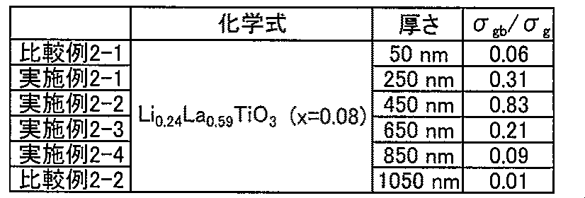
- ⁇ gb / ⁇ g increases when the thickness is in the range of 250 nm to 850 nm.
- ⁇ gb / ⁇ g was remarkably increased when the thickness was in the range of 250 nm to 600 nm, and further in the range of 300 nm to 550 nm.
- Comparative Example 3-1 A thin-film solid electrolyte material was obtained in the same manner as in Example 1-1 except that the amount of metal volatilized from the crucible was appropriately adjusted with a shutter.
- Comparative Examples 3-2 to 3-6 A thin-film solid electrolyte material was obtained in the same manner as in Comparative Example 3-1, except that the deposition time was appropriately changed.
- the thicknesses of the solid electrolyte materials obtained in Comparative Examples 3-2 to 3-6 were 250 nm, 450 nm, 650 nm, 850 nm, and 1050 nm, respectively.
- a bulk solid electrolyte material was synthesized in the same manner as in Patent Document 2. First, Li 2 CO 3 , La 2 O 3 and TiO 2 were mixed at a molar ratio of 1: 1: 4, mixed for 2 hours in a planetary ball mill using an acetone solvent, and then dried. Next, it heated at 800 degreeC for 4 hours, and then heated at 1150 degreeC for 12 hours. Next, the obtained sample was pulverized, molded at a pressure of 1 MPa, and then heated at 1350 ° C. for 6 hours. Thus, a solid electrolyte material that was a sintered bulk body was obtained. An SEM photograph of the surface of the obtained solid electrolyte material is shown in FIG.
- FIG. 7 a SEM photograph of the surface of the solid electrolyte material obtained in Example 1-1 is shown in FIG.
- the solid electrolyte material that is a sintered bulk body has insufficient bonding between crystal grains, and the crystal grain boundary becomes a bottleneck.
- Li ions are likely to stay at the grain boundaries, and Li ions cannot move smoothly.
- the solid electrolyte material of the present invention has good bonding between crystal grains. As a result, it is considered that Li ions can move smoothly without stagnation at crystal grain boundaries.
- the solid electrolyte material of the present invention has good bonding between crystal grains, it is considered that Li ion conductivity at the crystal grain boundary is increased.
Landscapes
- Chemical & Material Sciences (AREA)
- General Chemical & Material Sciences (AREA)
- Electrochemistry (AREA)
- Chemical Kinetics & Catalysis (AREA)
- Inorganic Chemistry (AREA)
- Engineering & Computer Science (AREA)
- Physics & Mathematics (AREA)
- Manufacturing & Machinery (AREA)
- Spectroscopy & Molecular Physics (AREA)
- General Physics & Mathematics (AREA)
- Condensed Matter Physics & Semiconductors (AREA)
- Conductive Materials (AREA)
- Secondary Cells (AREA)
Abstract
Description
まず、本発明の固体電解質材料について説明する。本発明の固体電解質材料は、一般式Li3x(La(2/3-x)-aM1a)(Ti1-bM2b)O3で表され、上記xは0<x<0.17を満たし、上記aは0≦a≦0.5を満たし、上記bは0≦b≦0.5を満たし、上記M1は、Sr、Na、Nd、Pr、Sm、Gd、Dy、Y、Eu、Tb、Baからなる群から選択される少なくとも一種であり、上記M2は、Mg、W、Mn、Al、Ge、Ru、Nb、Ta、Co、Zr、Hf、Fe、Cr、Gaからなる群から選択される少なくとも一種であり、結晶質であり、薄膜状であり、厚さが250nm~850nmの範囲内であることを特徴とするものである。
次に、本発明のリチウム電池について説明する。本発明のリチウム電池は、正極活物質を含有する正極活物質層と、負極活物質を含有する負極活物質層と、上記正極活物質層および上記負極活物質層の間に形成された固体電解質層とを含有するリチウム電池であって、上記固体電解質層が、上述した固体電解質材料を含有することを特徴とするものである。
以下、本発明のリチウム電池について、構成ごとに説明する。
まず、本発明における固体電解質層について説明する。本発明における固体電解質層は、上述した固体電解質材料を含有するものである。固体電解質層の厚さの範囲は、上述した固体電解質材料の厚さの範囲と同様であることが好ましい。
次に、本発明における正極活物質層について説明する。本発明における正極活物質層は、少なくとも正極活物質を含有する層であり、必要に応じて、導電化材、固体電解質材料および結着材の少なくとも一つを含有していても良い。正極活物質としては、例えばLiCoO2、LiMnO2、Li2NiMn3O8、LiVO2、LiCrO2、LiFePO4、LiCoPO4、LiNiO2、LiNi1/3Co1/3Mn1/3O2等を挙げることができる。
次に、本発明における負極活物質層について説明する。本発明における負極活物質層は、少なくとも負極活物質を含有する層であり、必要に応じて、導電化材、固体電解質材料および結着材の少なくとも一つを含有していても良い。負極活物質としては、例えば金属活物質およびカーボン活物質を挙げることができる。金属活物質としては、例えばIn、Al、SiおよびSn等を挙げることができる。一方、カーボン活物質としては、例えばメソカーボンマイクロビーズ(MCMB)、高配向性グラファイト(HOPG)、ハードカーボン、ソフトカーボン等を挙げることができる。
本発明のリチウム電池は、上述した固体電解質層、正極活物質層および負極活物質層を少なくとも有するものである。さらに通常は、正極活物質層の集電を行う正極集電体、および負極活物質層の集電を行う負極集電体を有する。正極集電体の材料としては、例えばSUS、アルミニウム、ニッケル、鉄、チタンおよびカーボン等を挙げることができ、中でもSUSが好ましい。一方、負極集電体の材料としては、例えばSUS、銅、ニッケルおよびカーボン等を挙げることができ、中でもSUSが好ましい。また、正極集電体および負極集電体の厚さや形状等については、リチウム電池の用途等に応じて適宜選択することが好ましい。また、本発明に用いられる電池ケースには、一般的なリチウム電池の電池ケースを用いることができる。電池ケースとしては、例えばSUS製電池ケース等を挙げることができる。
本発明のリチウム電池は、一次電池であっても良く、二次電池であっても良いが、中でも二次電池であることが好ましい。繰り返し充放電でき、例えば車載用電池として有用だからである。本発明のリチウム電池の形状としては、例えば、コイン型、ラミネート型、円筒型および角型等を挙げることができる。また、本発明のリチウム電池の製造方法は、上述したリチウム電池を得ることができる方法であれば特に限定されるものではなく、一般的なリチウム電池の製造方法と同様の方法を用いることができる。例えば、正極活物質層を構成する材料、固体電解質層を構成する材料、および負極活物質層を構成する材料を順次プレスすることにより、発電要素を作製し、この発電要素を電池ケースの内部に収納し、電池ケースをかしめる方法等を挙げることができる。
次に、本発明の固体電解質材料の製造方法について説明する。本発明の固体電解質材料の製造方法は、Li、La、Ti、M1(M1は、Sr、Na、Nd、Pr、Sm、Gd、Dy、Y、Eu、Tb、Baからなる群から選択される少なくとも一種である)、および、M2(M2は、Mg、W、Mn、Al、Ge、Ru、Nb、Ta、Co、Zr、Hf、Fe、Cr、Gaからなる群から選択される少なくとも一種である)から構成される原料を準備する原料準備工程と、上記原料を用いて、酸素を用いた反応性蒸着法により、基板上にLiLaTiO薄膜を形成する薄膜形成工程と、上記LiLaTiO薄膜を加熱することにより、一般式Li3x(La(2/3-x)-aM1a)(Ti1-bM2b)O3で表され、上記xは0<x<0.17を満たし、上記aは0≦a≦0.5を満たし、上記bは0≦b≦0.5を満たし、結晶質であり、薄膜状であり、厚さが250nm~850nmの範囲内である固体電解質材料を形成する加熱工程と、を有することを特徴とするものである。
以下、本発明の固体電解質材料の製造方法について、工程ごとに説明する。
まず、本発明における原料準備工程について説明する。本発明における原料準備工程は、Li、La、Ti、M1(M1は、Sr、Na、Nd、Pr、Sm、Gd、Dy、Y、Eu、Tb、Baからなる群から選択される少なくとも一種である)、および、M2(M2は、Mg、W、Mn、Al、Ge、Ru、Nb、Ta、Co、Zr、Hf、Fe、Cr、Gaからなる群から選択される少なくとも一種である)から構成される原料を準備する工程である。
次に、本発明における薄膜形成工程について説明する。本発明における薄膜形成工程は、上記原料を用いて、酸素を用いた反応性蒸着法により、基板上にLiLaTiO薄膜を形成する工程である。
次に、本発明における加熱工程について説明する。本発明における加熱工程は、上記LiLaTiO薄膜を加熱することにより、一般式Li3x(La(2/3-x)-aM1a)(Ti1-bM2b)O3で表され、上記xは0<x<0.17を満たし、上記aは0≦a≦0.5を満たし、上記bは0≦b≦0.5を満たし、結晶質であり、薄膜状であり、厚さが250nm~850nmの範囲内である固体電解質材料を形成する工程である。
本発明により得られる固体電解質材料については、上記「A.固体電解質材料」に記載した内容と同様であるので、ここでの記載は省略する。また、本発明においては、上述した固体電解質材料の製造方法により得られたことを特徴とする固体電解質材料を提供することができる。
まず、原料として、リチウム金属(ribbon、純度99.9%、Sigma Aldrich社製)、ランタン金属(純度99.9%、Sigma Aldrich社製)およびチタン金属(slug、純度99.98%、Alfa Aesar社製)を用意した。次に、リチウム金属を40cm3のpyrolytic boron nitride(PBN)製ルツボに入れ、チャンバー内に設置した。次に、ランタン金属およびチタン金属をそれぞれ40cm3のpyrolytic graphite製ルツボに入れ、同様にチャンバー内に設置した。また、基板として、Si/SiO2/Ti/Pt積層体(Nova Electronic Materials社製)を用い、蒸着面積を0.785cm2(φ10mm相当)とし、原料から基板までの距離を500mmとした。次に、チャンバー内を1×10⁻¹⁰mBar以下の高真空とした。
蒸着時間を適宜変更したこと以外は、実施例1-1と同様に薄膜状の固体電解質材料を得た。実施例1-2~1-4で得られた固体電解質材料の厚さは、それぞれ、450nm、650nm、850nmであった。
蒸着時間を適宜変更したこと以外は、実施例1-1と同様に薄膜状の固体電解質材料を得た。比較例1-1、1-2で得られた固体電解質材料の厚さは、それぞれ、50nm、1050nmであった。
実施例1~1~1-4、比較例1-1、1-2で得られた固体電解質材料のLiイオン伝導性を評価した。まず、基板上に形成された固体電解質材料の表面上に白金を蒸着させ、Pt/固体電解質材料/Ptの対称セルを作製した。次に、交流インピーダンス法により、結晶粒内でのLiイオン伝導率(σg)と、結晶粒界でのLiイオン伝導率(σgb)とを求め、σgb/σgを算出した。その結果を表1および図4に示す。

ルツボから揮発する金属の量をシャッターで適宜調整したこと以外は、実施例1-1と同様に薄膜状の固体電解質材料を得た。実施例2-1で得られた固体電解質材料の組成は、Li0.24La0.59TiO3(x=0.08)であり、厚さは250nmであった。
蒸着時間を適宜変更したこと以外は、実施例2-1と同様に薄膜状の固体電解質材料を得た。実施例2-2~2-4で得られた固体電解質材料の厚さは、それぞれ、450nm、650nm、850nmであった。
蒸着時間を適宜変更したこと以外は、実施例2-1と同様に薄膜状の固体電解質材料を得た。比較例2-1、2-2で得られた固体電解質材料の厚さは、それぞれ、50nm、1050nmであった。
実施例2~1~2-4、比較例2-1、2-2で得られた固体電解質材料のσgb/σgを算出した。測定方法は、上記の評価1と同様である。その結果を表2および図5に示す。
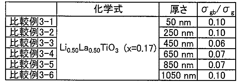
ルツボから揮発する金属の量をシャッターで適宜調整したこと以外は、実施例1-1と同様に薄膜状の固体電解質材料を得た。比較例3-1で得られた固体電解質材料の組成は、Li0.50La0.50TiO3(x=0.17)であり、厚さは50nmであった。
蒸着時間を適宜変更したこと以外は、比較例3-1と同様に薄膜状の固体電解質材料を得た。比較例3-2~3-6で得られた固体電解質材料の厚さは、それぞれ、250nm、450nm、650nm、850nm、1050nmであった。
比較例3~1~3-6で得られた固体電解質材料のσgb/σgを算出した。測定方法は、上記の評価1と同様である。その結果を表3および図6に示す。
特許文献2と同様の方法でバルク体の固体電解質材料を合成した。まず、Li2CO3、La2O3およびTiO2をモル比1:1:4で混合し、アセトン溶媒を用いて遊星型ボールミルで2時間混合した後、乾燥させた。次に、800℃で4時間加熱し、次に、1150℃で12時間加熱した。次に、得られた試料を粉砕し、1MPaの圧力で成型し、その後、1350℃で6時間加熱した。これにより、焼結したバルク体である固体電解質材料を得た。得られた固体電解質材料の表面のSEM写真を図7に示す。一方、実施例1-1で得られた固体電解質材料の表面のSEM写真を図8に示す。図7に示すように、焼結したバルク体である固体電解質材料は、結晶粒同士の接合が不十分であり、結晶粒界がボトルネックになる。その結果、Liイオンが結晶粒界で滞留しやすく、Liイオンがスムーズに動くことができなくなると考えられる。これに対して、図8に示すように、本発明の固体電解質材料は、結晶粒同士の接合が良好である。その結果、Liイオンが結晶粒界で滞留せずに、Liイオンがスムーズに動くことができると考えられる。このように、本発明の固体電解質材料は、結晶粒同士の接合が良好であるため、結晶粒界でのLiイオン伝導性が高くなると考えられる。
2 … 負極活物質層
3 … 固体電解質層
4 … 正極集電体
5 … 負極集電体
6 … 電池ケース
10 … リチウム電池
11 … チャンバー
12 … ルツボ
13 … 基板
14 … LiLaTiO薄膜
Claims (8)
- 一般式Li3x(La(2/3-x)-aM1a)(Ti1-bM2b)O3で表され、
前記xは0<x<0.17を満たし、前記aは0≦a≦0.5を満たし、前記bは0≦b≦0.5を満たし、
前記M1は、Sr、Na、Nd、Pr、Sm、Gd、Dy、Y、Eu、Tb、Baからなる群から選択される少なくとも一種であり、
前記M2は、Mg、W、Mn、Al、Ge、Ru、Nb、Ta、Co、Zr、Hf、Fe、Cr、Gaからなる群から選択される少なくとも一種であり、
結晶質であり、薄膜状であり、厚さが250nm~850nmの範囲内であることを特徴とする固体電解質材料。 - 前記xが、0.06≦x≦0.08を満たすことを特徴とする請求の範囲第1項に記載の固体電解質材料。
- 前記aおよび前記bが0であることを特徴とする請求の範囲第1項または第2項に記載の固体電解質材料。
- 正極活物質を含有する正極活物質層と、負極活物質を含有する負極活物質層と、前記正極活物質層および前記負極活物質層の間に形成された固体電解質層とを含有するリチウム電池であって、
前記固体電解質層が、請求の範囲第1項から第3項までのいずれかに記載の固体電解質材料を含有することを特徴とするリチウム電池。 - Li、La、Ti、M1(M1は、Sr、Na、Nd、Pr、Sm、Gd、Dy、Y、Eu、Tb、Baからなる群から選択される少なくとも一種である)、および、M2(M2は、Mg、W、Mn、Al、Ge、Ru、Nb、Ta、Co、Zr、Hf、Fe、Cr、Gaからなる群から選択される少なくとも一種である)から構成される原料を準備する原料準備工程と、
前記原料を用いて、酸素を用いた反応性蒸着法により、基板上にLiLaTiO薄膜を形成する薄膜形成工程と、
前記LiLaTiO薄膜を加熱することにより、一般式Li3x(La(2/3-x)-aM1a)(Ti1-bM2b)O3で表され、前記xは0<x<0.17を満たし、前記aは0≦a≦0.5を満たし、前記bは0≦b≦0.5を満たし、結晶質であり、薄膜状であり、厚さが250nm~850nmの範囲内である固体電解質材料を形成する加熱工程と、
を有することを特徴とする固体電解質材料の製造方法。 - 前記xが、0.06≦x≦0.08を満たすことを特徴とする請求の範囲第5項に記載の固体電解質材料の製造方法。
- 前記薄膜形成工程において、酸素プラズマを用いた反応性蒸着法により、前記LiLaTiO薄膜を形成することを特徴とする請求の範囲第5項または第6項に記載の固体電解質材料の製造方法。
- 前記基板が、正極活物質層または負極活物質層を有する部材であることを特徴とする請求の範囲第5項から第7項までのいずれかに記載の固体電解質材料の製造方法。
Priority Applications (4)
| Application Number | Priority Date | Filing Date | Title |
|---|---|---|---|
| US13/512,649 US9300008B2 (en) | 2010-04-13 | 2010-04-13 | Solid electrolyte material, lithium battery, and method of producing solid electrolyte material |
| PCT/JP2010/056604 WO2011128976A1 (ja) | 2010-04-13 | 2010-04-13 | 固体電解質材料、リチウム電池および固体電解質材料の製造方法 |
| CN201080066154.0A CN102859779B (zh) | 2010-04-13 | 2010-04-13 | 固体电解质材料、锂电池以及固体电解质材料的制造方法 |
| JP2012510494A JP5360296B2 (ja) | 2010-04-13 | 2010-04-13 | 固体電解質材料、リチウム電池および固体電解質材料の製造方法 |
Applications Claiming Priority (1)
| Application Number | Priority Date | Filing Date | Title |
|---|---|---|---|
| PCT/JP2010/056604 WO2011128976A1 (ja) | 2010-04-13 | 2010-04-13 | 固体電解質材料、リチウム電池および固体電解質材料の製造方法 |
Publications (1)
| Publication Number | Publication Date |
|---|---|
| WO2011128976A1 true WO2011128976A1 (ja) | 2011-10-20 |
Family
ID=44798369
Family Applications (1)
| Application Number | Title | Priority Date | Filing Date |
|---|---|---|---|
| PCT/JP2010/056604 Ceased WO2011128976A1 (ja) | 2010-04-13 | 2010-04-13 | 固体電解質材料、リチウム電池および固体電解質材料の製造方法 |
Country Status (4)
| Country | Link |
|---|---|
| US (1) | US9300008B2 (ja) |
| JP (1) | JP5360296B2 (ja) |
| CN (1) | CN102859779B (ja) |
| WO (1) | WO2011128976A1 (ja) |
Cited By (15)
| Publication number | Priority date | Publication date | Assignee | Title |
|---|---|---|---|---|
| JP2013073907A (ja) * | 2011-09-29 | 2013-04-22 | Toyota Motor Corp | 電極合材の製造方法 |
| JP2013151721A (ja) * | 2012-01-25 | 2013-08-08 | Toyota Motor Corp | 固体電解質膜の製造方法 |
| US8795902B2 (en) | 2010-04-13 | 2014-08-05 | Toyota Jidosha Kabushiki Kaisha | Solid electrolyte material, lithium battery, and method of producing solid electrolyte material |
| JP2014534591A (ja) * | 2011-11-02 | 2014-12-18 | アイ テン | 薄膜リチウムイオンマイクロ電池の製造方法及びその方法により得られたマイクロ電池 |
| JP2014534592A (ja) * | 2011-11-02 | 2014-12-18 | アイ テン | 全固体薄膜電池の製造方法 |
| JP2014535141A (ja) * | 2011-11-02 | 2014-12-25 | アイ テン | リチウムイオン電池用の固体電解質薄膜の製造方法 |
| US8945779B2 (en) | 2010-04-13 | 2015-02-03 | Toyota Jidosha Kabushiki Kaisha | Solid electrolyte material, lithium battery, and method of producing solid electrolyte material |
| WO2015046538A1 (ja) * | 2013-09-30 | 2015-04-02 | 京セラ株式会社 | 全固体型キャパシタ |
| US9196924B2 (en) | 2010-04-13 | 2015-11-24 | Toyota Jidosha Kabushiki Kaisha | Solid electrolyte material, lithium battery, and method of producing solid electrolyte material |
| JP2016509331A (ja) * | 2013-10-24 | 2016-03-24 | エルジー・ケム・リミテッド | 固体電解質粒子、この製造方法及びこれを含むリチウム二次電池 |
| CN106684440A (zh) * | 2016-07-28 | 2017-05-17 | 上海应用技术学院 | 一种LiBaLaZrWREAlO固体电解质的制备方法 |
| US9780407B2 (en) | 2013-08-29 | 2017-10-03 | Panasonic Intellectual Property Management Co., Ltd. | All-solid lithium secondary battery |
| JP2021136223A (ja) * | 2020-02-28 | 2021-09-13 | 三井金属鉱業株式会社 | リチウムイオン伝導体並びにそれを含む電極合剤及び電池 |
| US11959166B2 (en) | 2018-08-14 | 2024-04-16 | Massachusetts Institute Of Technology | Methods of fabricating thin films comprising lithium-containing materials |
| US11967694B2 (en) | 2018-05-07 | 2024-04-23 | I-Ten | Porous electrodes for electrochemical devices |
Families Citing this family (22)
| Publication number | Priority date | Publication date | Assignee | Title |
|---|---|---|---|---|
| US10411288B2 (en) * | 2011-11-29 | 2019-09-10 | Corning Incorporated | Reactive sintering of ceramic lithium-ion solid electrolytes |
| CN103187568A (zh) * | 2013-03-31 | 2013-07-03 | 复旦大学 | 一种锂离子电池正极材料及其合成方法 |
| WO2015029290A1 (ja) * | 2013-08-29 | 2015-03-05 | パナソニックIpマネジメント株式会社 | 全固体リチウム二次電池 |
| GB201400274D0 (en) | 2014-01-08 | 2014-02-26 | Ilika Technologies Ltd | Vapour deposition method for preparing amorphous lithium-containing compounds |
| GB201400277D0 (en) * | 2014-01-08 | 2014-02-26 | Ilika Technologies Ltd | Vapour deposition method for preparing crystalline lithium-containing compounds |
| GB201400276D0 (en) | 2014-01-08 | 2014-02-26 | Ilika Technologies Ltd | Vapour deposition method for fabricating lithium-containing thin film layered structures |
| CN105047989B (zh) * | 2015-07-09 | 2017-07-11 | 山东玉皇新能源科技有限公司 | 一种钙钛矿型固体电解质锂镧钛氧化合物的电化学制备方法 |
| JPWO2017154922A1 (ja) * | 2016-03-08 | 2018-11-22 | 株式会社村田製作所 | 固体電解質、全固体電池、固体電解質の製造方法及び全固体電池の製造方法 |
| KR102435872B1 (ko) | 2016-06-15 | 2022-08-23 | 이리카 테크놀로지스 리미티드 | 전해질 및 전극 보호층으로서의 리튬 보로실리케이트 유리 |
| JP6669268B2 (ja) * | 2016-09-21 | 2020-03-18 | 株式会社村田製作所 | 固体電解質及び全固体電池 |
| JP6796784B2 (ja) * | 2016-10-12 | 2020-12-09 | パナソニックIpマネジメント株式会社 | 固体電解質およびそれを用いた二次電池 |
| CN106518063A (zh) * | 2016-11-18 | 2017-03-22 | 郑州丽福爱生物技术有限公司 | 一种添加氧化锶的高介微波介质材料及其制备方法及应用 |
| WO2019017994A1 (en) * | 2017-07-21 | 2019-01-24 | Quantumscape Corporation | ACTIVE AND PASSIVE BATTERY PRESSURE MANAGEMENT |
| CN107732296B (zh) * | 2017-10-09 | 2020-02-04 | 中国科学院深圳先进技术研究院 | 一种全固态锂离子电池固态电解质的制备方法 |
| GB201814039D0 (en) | 2018-08-29 | 2018-10-10 | Ilika Tech Ltd | Method |
| CN109301138B (zh) * | 2018-09-28 | 2020-07-10 | 东北大学 | 一种以锂离子固体电解质片为隔膜钮扣锂电池及制备方法 |
| CN109285983B (zh) * | 2018-09-28 | 2020-07-14 | 东北大学 | 以锂离子固体电解质片为隔膜的钮扣锂电池及其制备方法 |
| JP7220370B2 (ja) * | 2018-11-28 | 2023-02-10 | パナソニックIpマネジメント株式会社 | 固体電解質およびそれを備えた蓄電デバイス |
| JP7329776B2 (ja) * | 2018-12-28 | 2023-08-21 | パナソニックIpマネジメント株式会社 | 固体電解質材料、およびこれを用いた電池 |
| US20220263092A1 (en) * | 2021-02-08 | 2022-08-18 | Nissan North America, Inc. | Composite Cathode Material for Lithium Batteries |
| CN113363563A (zh) * | 2021-05-21 | 2021-09-07 | 万向一二三股份公司 | 一种复合固态电解质及其制备方法、应用 |
| CN115504770B (zh) * | 2022-09-13 | 2023-07-21 | 景德镇陶瓷大学 | 一种过渡金属离子与Nd3+共掺杂型固体电解质陶瓷材料及其制备方法 |
Citations (3)
| Publication number | Priority date | Publication date | Assignee | Title |
|---|---|---|---|---|
| JP2007101536A (ja) * | 2005-09-06 | 2007-04-19 | Sumitomo Electric Ind Ltd | ガスセンサ及びその製造方法 |
| JP2008059843A (ja) * | 2006-08-30 | 2008-03-13 | Kyoto Univ | 固体電解質層及びその製造方法 |
| JP2009215130A (ja) * | 2008-03-12 | 2009-09-24 | Sumitomo Electric Ind Ltd | 電解質粒子 |
Family Cites Families (8)
| Publication number | Priority date | Publication date | Assignee | Title |
|---|---|---|---|---|
| EP1359636A1 (en) * | 2001-09-03 | 2003-11-05 | Matsushita Electric Industrial Co., Ltd. | Method for manufacturing electrochemical device |
| US6835493B2 (en) * | 2002-07-26 | 2004-12-28 | Excellatron Solid State, Llc | Thin film battery |
| KR20080074157A (ko) | 2005-12-02 | 2008-08-12 | 마쯔시다덴기산교 가부시키가이샤 | 음극 활물질, 이것을 이용한 음극 및 리튬이온 이차전지 |
| CN100422381C (zh) * | 2005-12-29 | 2008-10-01 | 复旦大学 | 电子束热蒸发制备锂镧钛氧薄膜的方法 |
| EP1895295A3 (en) | 2006-09-01 | 2010-01-20 | Sumitomo Electric Industries, Ltd. | Gas sensor and method of manufacturing the same |
| US9093707B2 (en) * | 2007-06-11 | 2015-07-28 | Alliance For Sustainable Energy, Llc | MultiLayer solid electrolyte for lithium thin film batteries |
| JP5217562B2 (ja) | 2008-03-28 | 2013-06-19 | 住友電気工業株式会社 | 固体電解質膜およびリチウム電池 |
| CN101325094B (zh) * | 2008-07-25 | 2013-04-03 | 清华大学 | 一种锂镧钛氧llto复合固态电解质材料及其合成方法 |
-
2010
- 2010-04-13 JP JP2012510494A patent/JP5360296B2/ja not_active Expired - Fee Related
- 2010-04-13 WO PCT/JP2010/056604 patent/WO2011128976A1/ja not_active Ceased
- 2010-04-13 US US13/512,649 patent/US9300008B2/en not_active Expired - Fee Related
- 2010-04-13 CN CN201080066154.0A patent/CN102859779B/zh not_active Expired - Fee Related
Patent Citations (3)
| Publication number | Priority date | Publication date | Assignee | Title |
|---|---|---|---|---|
| JP2007101536A (ja) * | 2005-09-06 | 2007-04-19 | Sumitomo Electric Ind Ltd | ガスセンサ及びその製造方法 |
| JP2008059843A (ja) * | 2006-08-30 | 2008-03-13 | Kyoto Univ | 固体電解質層及びその製造方法 |
| JP2009215130A (ja) * | 2008-03-12 | 2009-09-24 | Sumitomo Electric Ind Ltd | 電解質粒子 |
Cited By (20)
| Publication number | Priority date | Publication date | Assignee | Title |
|---|---|---|---|---|
| US8945779B2 (en) | 2010-04-13 | 2015-02-03 | Toyota Jidosha Kabushiki Kaisha | Solid electrolyte material, lithium battery, and method of producing solid electrolyte material |
| US8795902B2 (en) | 2010-04-13 | 2014-08-05 | Toyota Jidosha Kabushiki Kaisha | Solid electrolyte material, lithium battery, and method of producing solid electrolyte material |
| US9196924B2 (en) | 2010-04-13 | 2015-11-24 | Toyota Jidosha Kabushiki Kaisha | Solid electrolyte material, lithium battery, and method of producing solid electrolyte material |
| JP2013073907A (ja) * | 2011-09-29 | 2013-04-22 | Toyota Motor Corp | 電極合材の製造方法 |
| JP2018186099A (ja) * | 2011-11-02 | 2018-11-22 | アイ テン | 薄膜リチウムイオンマイクロ電池の製造方法及びその方法により得られたマイクロ電池 |
| JP2014534592A (ja) * | 2011-11-02 | 2014-12-18 | アイ テン | 全固体薄膜電池の製造方法 |
| JP2014534591A (ja) * | 2011-11-02 | 2014-12-18 | アイ テン | 薄膜リチウムイオンマイクロ電池の製造方法及びその方法により得られたマイクロ電池 |
| JP2014535141A (ja) * | 2011-11-02 | 2014-12-25 | アイ テン | リチウムイオン電池用の固体電解質薄膜の製造方法 |
| JP2013151721A (ja) * | 2012-01-25 | 2013-08-08 | Toyota Motor Corp | 固体電解質膜の製造方法 |
| US9780407B2 (en) | 2013-08-29 | 2017-10-03 | Panasonic Intellectual Property Management Co., Ltd. | All-solid lithium secondary battery |
| US10115534B2 (en) | 2013-09-30 | 2018-10-30 | Kyocera Corporation | All-solid-state capacitor with solid electrolyte having a polycrystalline structure |
| WO2015046538A1 (ja) * | 2013-09-30 | 2015-04-02 | 京セラ株式会社 | 全固体型キャパシタ |
| JPWO2015046538A1 (ja) * | 2013-09-30 | 2017-03-09 | 京セラ株式会社 | 全固体型キャパシタ |
| US10128531B2 (en) | 2013-10-24 | 2018-11-13 | Lg Chem, Ltd. | Solid electrolyte particles, preparation method thereof, and lithium secondary battery comprising the same |
| JP2016509331A (ja) * | 2013-10-24 | 2016-03-24 | エルジー・ケム・リミテッド | 固体電解質粒子、この製造方法及びこれを含むリチウム二次電池 |
| CN106684440A (zh) * | 2016-07-28 | 2017-05-17 | 上海应用技术学院 | 一种LiBaLaZrWREAlO固体电解质的制备方法 |
| US11967694B2 (en) | 2018-05-07 | 2024-04-23 | I-Ten | Porous electrodes for electrochemical devices |
| US11959166B2 (en) | 2018-08-14 | 2024-04-16 | Massachusetts Institute Of Technology | Methods of fabricating thin films comprising lithium-containing materials |
| JP2021136223A (ja) * | 2020-02-28 | 2021-09-13 | 三井金属鉱業株式会社 | リチウムイオン伝導体並びにそれを含む電極合剤及び電池 |
| JP7349935B2 (ja) | 2020-02-28 | 2023-09-25 | 三井金属鉱業株式会社 | リチウムイオン伝導体並びにそれを含む電極合剤及び電池 |
Also Published As
| Publication number | Publication date |
|---|---|
| US9300008B2 (en) | 2016-03-29 |
| US20120237835A1 (en) | 2012-09-20 |
| CN102859779B (zh) | 2016-10-19 |
| CN102859779A (zh) | 2013-01-02 |
| JPWO2011128976A1 (ja) | 2013-07-11 |
| JP5360296B2 (ja) | 2013-12-04 |
Similar Documents
| Publication | Publication Date | Title |
|---|---|---|
| JP5360296B2 (ja) | 固体電解質材料、リチウム電池および固体電解質材料の製造方法 | |
| JP5692221B2 (ja) | 固体電解質材料、リチウム電池および固体電解質材料の製造方法 | |
| JP5267678B2 (ja) | 固体電解質材料、リチウム電池および固体電解質材料の製造方法 | |
| JP2011222415A (ja) | 固体電解質材料、リチウム電池および固体電解質材料の製造方法 | |
| JP5358522B2 (ja) | 固体電解質材料およびリチウム電池 | |
| JP5392402B2 (ja) | 固体電解質材料、リチウム電池および固体電解質材料の製造方法 | |
| Wang et al. | Facile synthesis and electrochemical properties of CoMn 2 O 4 anodes for high capacity lithium-ion batteries | |
| JP5841014B2 (ja) | 固体電解質薄膜の製造方法、固体電解質薄膜、および固体電池 | |
| JP6662802B2 (ja) | 酸化物全固体電池 | |
| JP5678928B2 (ja) | 全固体電池およびその製造方法 | |
| JP7107272B2 (ja) | 硫化物固体電解質、硫化物固体電解質の製造方法、電極体および全固体電池 | |
| JP2023001199A (ja) | 電気化学素子用電極活物質およびその製造方法、電気化学素子用電極材料、電気化学素子用電極、電気化学素子、並びに移動体 | |
| WO2022190933A1 (ja) | 電気化学素子用電極活物質、電気化学素子用電極材料、電気化学素子用電極、電気化学素子および移動体 | |
| JP5531347B2 (ja) | 自己支持形金属硫化物系2次元ナノ構造体の負極活物質及びその製造方法 | |
| WO2022259797A1 (ja) | 被覆正極活物質、正極材料、および電池 | |
| EP4350831A1 (en) | Oxide-based film sheet, oxide-based solid electrolyte sheet, and all-solid lithium secondry battery | |
| CN111052489A (zh) | 锂离子二次电池的制造方法、锂离子二次电池 | |
| WO2024144720A1 (en) | Method to produce cathode material for energy storage devices | |
| JP2013161525A (ja) | 負極活物質、リチウム電池および負極活物質の製造方法 |
Legal Events
| Date | Code | Title | Description |
|---|---|---|---|
| WWE | Wipo information: entry into national phase |
Ref document number: 201080066154.0 Country of ref document: CN |
|
| 121 | Ep: the epo has been informed by wipo that ep was designated in this application |
Ref document number: 10849814 Country of ref document: EP Kind code of ref document: A1 |
|
| WWE | Wipo information: entry into national phase |
Ref document number: 2012510494 Country of ref document: JP |
|
| WWE | Wipo information: entry into national phase |
Ref document number: 13512649 Country of ref document: US |
|
| NENP | Non-entry into the national phase |
Ref country code: DE |
|
| 122 | Ep: pct application non-entry in european phase |
Ref document number: 10849814 Country of ref document: EP Kind code of ref document: A1 |