WO2011125824A1 - 電子写真用ブレード - Google Patents
電子写真用ブレード Download PDFInfo
- Publication number
- WO2011125824A1 WO2011125824A1 PCT/JP2011/058184 JP2011058184W WO2011125824A1 WO 2011125824 A1 WO2011125824 A1 WO 2011125824A1 JP 2011058184 W JP2011058184 W JP 2011058184W WO 2011125824 A1 WO2011125824 A1 WO 2011125824A1
- Authority
- WO
- WIPO (PCT)
- Prior art keywords
- polyurethane
- blade
- hardness
- backup
- edge portion
- Prior art date
- Legal status (The legal status is an assumption and is not a legal conclusion. Google has not performed a legal analysis and makes no representation as to the accuracy of the status listed.)
- Ceased
Links
Images





Classifications
-
- G—PHYSICS
- G03—PHOTOGRAPHY; CINEMATOGRAPHY; ANALOGOUS TECHNIQUES USING WAVES OTHER THAN OPTICAL WAVES; ELECTROGRAPHY; HOLOGRAPHY
- G03G—ELECTROGRAPHY; ELECTROPHOTOGRAPHY; MAGNETOGRAPHY
- G03G21/00—Arrangements not provided for by groups G03G13/00 - G03G19/00, e.g. cleaning, elimination of residual charge
- G03G21/0005—Arrangements not provided for by groups G03G13/00 - G03G19/00, e.g. cleaning, elimination of residual charge for removing solid developer or debris from the electrographic recording medium
- G03G21/0011—Arrangements not provided for by groups G03G13/00 - G03G19/00, e.g. cleaning, elimination of residual charge for removing solid developer or debris from the electrographic recording medium using a blade; Details of cleaning blades, e.g. blade shape, layer forming
- G03G21/0023—Arrangements not provided for by groups G03G13/00 - G03G19/00, e.g. cleaning, elimination of residual charge for removing solid developer or debris from the electrographic recording medium using a blade; Details of cleaning blades, e.g. blade shape, layer forming with electric bias
-
- G—PHYSICS
- G03—PHOTOGRAPHY; CINEMATOGRAPHY; ANALOGOUS TECHNIQUES USING WAVES OTHER THAN OPTICAL WAVES; ELECTROGRAPHY; HOLOGRAPHY
- G03G—ELECTROGRAPHY; ELECTROPHOTOGRAPHY; MAGNETOGRAPHY
- G03G21/00—Arrangements not provided for by groups G03G13/00 - G03G19/00, e.g. cleaning, elimination of residual charge
- G03G21/0005—Arrangements not provided for by groups G03G13/00 - G03G19/00, e.g. cleaning, elimination of residual charge for removing solid developer or debris from the electrographic recording medium
- G03G21/0011—Arrangements not provided for by groups G03G13/00 - G03G19/00, e.g. cleaning, elimination of residual charge for removing solid developer or debris from the electrographic recording medium using a blade; Details of cleaning blades, e.g. blade shape, layer forming
- G03G21/0017—Details relating to the internal structure or chemical composition of the blades
Definitions
- the present invention relates to a cleaning blade for removing toner remaining on an image carrier such as a photosensitive drum, a transfer belt, and an intermediate transfer member used in an electrophotographic apparatus.
- the present invention also relates to a developing blade used in the developing process. Further, the present invention relates to a charging blade for applying an electric charge to the image carrier.
- the blades used are single-layer blades (single seed materials).
- a multilayer blade laminate of flat sheet of multilayer material
- blade stick slip becomes large at high temperatures and high humidity.
- the service life cannot be satisfied, and therefore, measures have been taken to compensate for the problem by machine control or the like.
- the tan ⁇ peak temperature is ⁇ 3 to 11 ° C.
- the tan ⁇ peak value is ⁇ 3 when the cleaning performance under low temperature and low humidity is emphasized. It is so favorable that it is ° C (low temperature). On the other hand, the durability under high temperature and high humidity is better as the tan ⁇ peak value is 11 ° C. (high temperature). Therefore, in the case of a single-layer blade, it was a blade that considered the balance between low-temperature cleaning performance and durability (depending on handling in individual machines). In the two-layer blade, for example, a rubber having excellent high temperature characteristics is used for the edge layer and a rubber having excellent low temperature characteristics is used for the backup layer.
- Patent Document 1 Japanese Patent Application Laid-Open No. 2007-30385
- Patent Document 2 Japanese Patent Laid-Open No.
- 2007-163676 is a technique using a casting method, in which a liquid synthetic resin forming a partial layer is cast in a bead shape on one mold of a split mold. Later, a method of manufacturing a blade was proposed in which a mold was assembled, a liquid synthetic resin for forming a base layer was cast, and then heat cured to form a blade material.
- Patent Document 3 Japanese Patent Laid-Open No. 2009-300551
- a cleaning blade capable of preventing toner from slipping even under low temperature conditions a polyurethane for an electrophotographic apparatus provided with an edge portion and a backup layer made of different materials is used.
- a cleaning blade with a thickness ⁇ width of the edge portion of 0.03 to 0.4 ⁇ 0.03 to 4 mm was proposed.
- a blade that satisfies low temperature (10 ° C.) cleaning performance and does not cause blade reversal or blade squealing even when the hardness of the film of the image bearing member is increased or the printing speed is increased.
- ether polyurethane as the edge and nip.
- the blade of the present invention is provided with high-hardness polyurethane only on the edge portion that contacts the image carrier and the like, and the backup portion is made of polyurethane with conventional hardness, so that the friction at the contact portion can be lowered and elastic.
- the behavior is shared by the backup part.
- blade which can be provided for practical use is provided by using the polyurethane from which the specific material described in the claim differs. 1.
- the polyurethane forming the edge part is harder than the polyurethane forming the backup part, and the JIS-A hardness of the polyurethane forming the backup part 65 to 80, and the polyurethane forming the edge portion has (1) JIS-A hardness of 75 to 100 and tan ⁇ peak temperature of ⁇ 20 to ⁇ 1 ° C. or (2) JIS-A hardness of 85 A blade characterized by ⁇ 100 and a tan ⁇ peak temperature of ⁇ 20 to 60 ° C. 2.
- the polyurethane forming the edge portion is made of an ester polyurethane, and the polyurethane forming the backup portion is an ether polyurethane or an ester polyurethane.
- the polyurethane that forms the edge portion is made of an ether-based polyurethane, and the polyurethane that forms the backup portion is an ether-based polyurethane,
- the JIS-A hardness of the polyurethane forming the backup part is 65-80
- the polyurethane forming the edge portion is characterized in that (1) JIS-A hardness is 75 to 100 and tan ⁇ peak temperature is ⁇ 20 to 60 ° C.
- the ether-based polyurethane that forms the edge portion uses polytetraethylene glycol as the polyether polyol, the saturated fatty acid alkali metal salt and the organotin compound as the curing agent, and the polyurethane that forms the backup portion serves as the ether-based polyurethane.
- Torque is 0.8 kgf / cm or less under the following measurement conditions. ⁇ 4.
- the blade according to any one of the above. Measurement conditions The blade is tangentially penetrated into the OPC drum, and the OPC drum is rotated in a direction opposite to the penetration direction so that the linear velocity is 200 mm / s.
- a polyurethane having an edge hardness of 80 degrees or more uses a saturated fatty acid alkali metal salt as a curing catalyst. ⁇ 5.
- the edge portion has a color different from that of the backup layer.
- 1. Thickness ⁇ width of edge portion is 0.03 to 0.4 ⁇ 0.03 to 4.0 mm ⁇ 7.
- the blade is a cleaning blade, a developing blade or a charging blade. ⁇ 8.
- the polyurethane forming the edge part is harder than the polyurethane forming the backup part, and the JIS-A hardness of the polyurethane forming the backup part 65 to 80, and the polyurethane forming the edge portion has (1) JIS-A hardness of 75 to 100 and tan ⁇ peak temperature of ⁇ 20 to ⁇ 1 ° C.
- a method of manufacturing the blade used is the method in which the polyurethane raw material for forming the edge portion is first poured into a cylindrical mold, cured while rotating the mold, semi-cured, and then the polyurethane raw material for forming the backup portion is prepared.
- a method for manufacturing a blade comprising: taking out a belt-shaped blade material by curing while pouring and rotating, cutting the length to a fixed size, and then cutting and molding an edge including an edge portion.
- the polyurethane forming the edge portion is made of an ester-based polyurethane
- the polyurethane forming the backup portion is an ether-based polyurethane or an ester-based polyurethane.
- the polyurethane that forms the edge part is made of ether-based polyurethane
- the polyurethane that forms the backup part is ether-based polyurethane
- the polyurethane that forms the backup part has a JIS-A hardness of 65 to 80, and forms the edge part.
- the polyurethane has a JIS-A hardness of 75 to 100 and a tan ⁇ peak temperature of ⁇ 20 to 60 ° C.
- the polyurethane forming the edge portion is made of an ester-based polyurethane
- the polyurethane forming the backup portion is an ether-based polyurethane or an ester-based polyurethane
- the polyurethane that forms the backup part has a JIS-A hardness of 65 to 80
- the polyurethane that forms the edge part has (1) a JIS-A hardness of 75 to 100 and a tan ⁇ peak temperature of ⁇ 20 to ⁇ 1 ° C.
- a method of manufacturing a blade having a JIS-A hardness of 85 to 100 and a tan ⁇ peak temperature of ⁇ 20 to 60 ° C. comprising a forming groove on the outer periphery and a heating device inside. And a synthetic resin supply hand in the molding groove along the outer periphery of the molding drum.
- the endless belt that rotates in synchronization with the rotation of the molding drum while sequentially covering the molding grooves of the molding drum is sequentially arranged, and the synthetic resin material supplied to the molding grooves is formed by the molding space formed by the endless belt and the molding grooves.
- a method for manufacturing a blade comprising cutting and molding an edge including the blade.
- the polyurethane forming the edge portion is made of an ester-based polyurethane
- the polyurethane forming the backup portion is an ether-based polyurethane or an ester-based polyurethane
- the polyurethane that forms the backup portion has a JIS-A hardness of 65 to 80
- the polyurethane that forms the edge portion is (1) a JIS-A hardness of 75 to 100 and a tan ⁇ peak temperature of ⁇ 20 to ⁇ 1 ° C., or (2)
- the split mold method is used, in which the raw material is cast, and the mold is cured after polymerization and curing.
- a blade manufacturing method comprising: injecting, curing and removing a mold to obtain a blade material, and cutting an edge of the blade material to mold an edge portion.
- the polyurethane forming the edge portion is made of an ester-based polyurethane
- the polyurethane forming the backup portion is an ether-based polyurethane or an ester-based polyurethane
- the polyurethane that forms the backup portion has a JIS-A hardness of 65 to 80
- the polyurethane that forms the edge portion is (1) a JIS-A hardness of 75 to 100 and a tan ⁇ peak temperature of ⁇ 20 to ⁇ 1 ° C.
- a method of manufacturing a blade having a JIS-A hardness of 85 to 100 and a tan ⁇ peak temperature of ⁇ 20 to 60 ° C., which is liquid in a cavity formed by assembling mold members A split mold method in which polyurethane raw material is casted and then demolded after polymerization and curing.
- a molding die having a bottom side as a side on which a tip of the blade including the edge portion is formed, the liquid forming the edge portion in a state where the molding die is inclined from the vertical direction.
- a method of manufacturing a blade comprising casting a polyurethane raw material, then injecting a polyurethane raw material that forms a backup layer in a state in which the polyurethane raw material is returned to a vertical state, curing, and then demolding.
- the polyurethane raw material forming the edge portion is an ester polyurethane raw material
- the polyurethane raw material forming the backup layer is an ether polyurethane raw material.
- the blade manufacturing method according to any one of the above. 17 9.
- a polyurethane colored in a color different from that of the polyurethane forming the backup layer is used as the polyurethane forming the edge portion.
- the blade is a cleaning blade, a developing blade or a charging blade. ⁇ 17.
- the blade of the present invention is provided with high-hardness polyurethane only on the edge portion that contacts the image carrier and the like, and the backup portion is made of polyurethane with conventional hardness, so that the friction at the contact portion can be lowered and elastic.
- the behavior is shared by the backup part.
- the blade which can be used for practical use is provided by using the polyurethane from which the specific material described in the claim differs.
- the present invention can provide a blade capable of realizing low friction even when contacting at a higher pressure than before.
- the blade realized by the present invention has a low ⁇ , and as a result, can contribute to the reduction of the power consumption of the apparatus, can extend the life of the image carrier, and can extend the life of the apparatus. .
- the film hardness of the image carrier is improved, and even when the printing speed is increased, blade reversal and blade squeal do not occur. Further, the cleaning performance of an alternative that is a substitute for an image carrier and has a low surface roughness at a low cost can be satisfied.
- the reduction in friction can reduce the load applied to the image carrier during driving, leading to a reduction in power consumption and a longer life of the machine.
- a saturated fatty acid alkali metal salt as a curing catalyst
- a high-hardness polyurethane suitable for the edge portion could be realized.
- a polyurethane having a JIS-A hardness of 80 degrees or more, particularly 100 degrees can be realized.
- the location of the edge portion can be easily detected, and inspection and assembly work can be improved.
- the range of the preferable edge portion is 0.03 to 0.4 ⁇ 0.03 to 4 mm in thickness ⁇ width, and if both are transparent, it is difficult to distinguish, but if they are differently colored, blade manufacture Not only the process but also the assembly to the electrophotographic apparatus and subsequent confirmation are easy, and the occurrence of mistakes can be suppressed.
- a thermosetting polyurethane is suitable, an ester polyurethane as an edge polyurethane, and an ester polyurethane and an ether polyurethane as a polyurethane forming a backup layer.
- Especially ether type is suitable.
- a continuous molding method using a molding drum and an individual molding method using a casting mold are provided.
- a casting mold by injecting the liquid urethane for forming the edge portion in an inclined state, an edge portion having a triangular cross section can be formed, and after being semi-cured, the edge portion is returned to an upright state and backed up.
- the polyurethane raw material forming the portion it is possible to provide a molding method using a casting mold that can efficiently form the edge portion.
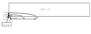
- the figure which shows the cross section of a cleaning blade typically.
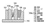
- Sectional drawing which shows the outline of a split mold structure.
- the blade of the present invention is provided with high-hardness polyurethane only on the edge portion that contacts the image carrier and the like, and the backup portion is made of polyurethane with conventional hardness, so that the friction at the contact portion can be lowered and elastic.
- the behavior is shared by the backup part.
- blade which can be used practically is provided by using the polyurethane from which a specific material differs.
- ⁇ Blade shape and configuration> In the case of a conventional blade, for example, a single layer blade, when the hardness is increased, the elasticity is lost.
- a method for increasing the hardness of the edge layer by using a two-layer structure as proposed as a multi-layer blade, but the elasticity of the rubber cannot be sufficiently maintained, and the edge tip necessary as a blade material is required.
- the part does not have enough stick slip and does not function as a cleaning blade.
- the present invention when only the edge portion is made extremely hard, it is governed by the rubber physical properties of most of the backup portions and can sufficiently maintain the elasticity of the rubber. That is, an appropriate stick slip can be performed and a sufficient function as a blade can be exhibited.
- the edge part high in hardness (85 degrees or more in JIS-A)
- the ⁇ can be reduced by 20% or more by the conventional conventional blade.
- the value of the tan ⁇ peak temperature is , Not a constraint.
- another means for lowering ⁇ is effective to increase the elastic modulus of rubber.
- the tan ⁇ peak temperature is in the range of ⁇ 15 to ⁇ 3 ° C.
- the JIS-A hardness is 75. If it is held more than once, the effect can be obtained.
- a fast-curing catalyst Na acetate
- a fast-curing catalyst Na acetate
- ether-based polyurethane has been considered to have low wear resistance and is not suitable for the edge portion, but provided a blade capable of exhibiting excellent printing performance by selecting a curing agent different from the backup portion.
- the polyurethane that forms the edge portion is an ether-based polyurethane, the polytetramethylene glycol (PTMG) as the polyether polyol, the saturated fatty acid alkali metal salt and the organotin compound as part of the curing agent, and the polyurethane that forms the backup portion.
- PTMG polytetramethylene glycol
- amine compound as a part of the curing agent.
- the permanent distortion is cut in such a manner that the rubber part is 10 mm after the blade is manufactured to obtain a sample piece.
- a sample piece is joined to a sheet metal like a blade, this sample piece is set on a dedicated jig for pressure welding storage, and the tip is brought into contact with the jig to obtain an initial value (reference).
- a 1.4 mm blade is pushed in, the rubber is deformed and left in a storage environment for 3 days. After completion of the storage period, the deformation was released, and after standing at 23 ° C. for 4 hours, data was collected after 1 minute and 4 hours.
- this permanent distortion can be suppressed to within 0.1 mm.
- an ether-based polyurethane having a JIS-A hardness of 77 to 78 degrees at the edge portion achieved this permanent distortion within 0.1 mm.
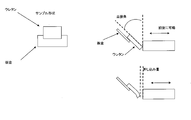
- the outline of the permanent strain test method is shown in FIG.
- the blade of the present invention is joined to a metal support member and used as a cleaning blade or the like.
- a cross-sectional view of the blade of the present invention is shown in FIG.
- the edge portion and the backup portion serving as the base are formed of different polyurethanes around the edge that is brought into pressure contact with the surface of the image carrier or the like.
- the polyurethane forming the edge portion is harder than the polyurethane forming the backup portion.
- the polyurethane that forms the backup portion has a JIS-A hardness of 65 to 80, and the polyurethane that forms the edge portion is (1) a JIS-A hardness of 75 to 100 and a tan ⁇ peak temperature of ⁇ 20 to ⁇ 1 ° C.
- the edge part is an ester-based polyurethane that forms the edge part.
- (1) JIS-A hardness is 75 to 100 and tan ⁇ peak temperature is ⁇ 20 to ⁇ 3 ° C. or (2) JIS-A
- the hardness is 85 to 100 and the tan ⁇ peak temperature is ⁇ 3 to 60 ° C.
- the size of the edge portion is preferably 0.03 to 0.4 ⁇ 0.03 to 4 mm in thickness ⁇ width.
- a saturated fatty acid alkali metal salt is effective as a curing catalyst for the formation of high-hardness polyurethane having a JIS-A hardness of 80 degrees or more for the edge portion.
- saturated fatty acid alkali metal salts Na acetate
- Other catalysts organotin compounds, tertiary amine compounds
- the ether-based polyurethane that forms the edge portion is polytetramethylene glycol (PTMG) as a polyether polyol, and a saturated fatty acid alkali metal as a part of the curing agent. It is suitable to use a salt and an organic tin compound as the polyurethane that forms the backup portion as an ether polyurethane, polytetramethylene glycol (PTMG) as the polyether polyol, and an amine compound as part of the curing agent.
- PTMG polytetramethylene glycol
- the backup portion (base portion) is an ether-based polyurethane or an ester-based polyurethane, and the polyurethane has a JIS-A hardness of preferably 65 to 80 regardless of whether the surface is measured from the front or back.
- the catalyst type is not limited regardless of the edge portion or backup portion.
- the blade of the present invention can be attached to a support member and used as a cleaning blade, a developing blade, or a charging blade.
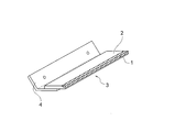
- a polyurethane blade 3 comprising a partial layer 1 at the edge portion and a base layer 2 as a backup layer shown in FIG.
- ester polyurethane for the edge portion
- ether polyurethane for the base portion.
- a special combination of ether-based polyurethanes can be used.
- the blade used in the present invention is suitably made of a thermosetting polyurethane resin.
- a polyurethane composition containing a polyisocyanate and a polyol is used.
- a layer including an edge portion or a nip portion uses an ester-based polyurethane
- a base portion other than the layer including an edge portion or a nip portion uses a combination of an ether-based polyurethane.
- ether polyurethane can be selectively used for the edge portion or the nip portion and the base portion.
- the polyurethane raw material used in the present invention is preferably non-solvent type thermosetting.
- an ester polyurethane or an ether polyurethane disclosed in Japanese Patent Application No. 2007-18162 filed earlier by the present applicant can be used. If a colorant is added to the edge portion polyurethane resin to give a color different from that of the backup layer, the size of the edge portion can be clearly identified. It becomes easy to trim and form the edge size after the polyurethane is cured.
- the polyurethane forming the edge portion and the backup portion is an ether-based polyurethane
- the polyurethane forming the edge portion is an ether-based polyurethane, polytetramethylene glycol (PTMG) as the polyether polyol, and saturated fatty acid alkali as the curing agent.
- PTMG polytetramethylene glycol
- a metal salt and an organic tin compound as the polyurethane that forms the backup portion as an ether polyurethane, polytetramethylene glycol (PTMG) as the polyether polyol, and an amine compound as part of the curing agent.
- PTMG polytetramethylene glycol
- Ester polyol An ester polyurethane is suitable for the edge layer.
- Polyester polyols such as polyester diol and polyester triol are suitable.
- ester polyurethane can be used as a backup layer, it has a lower hardness than the edge layer.
- the polyester polyol is produced from a polybasic organic acid and a polyol.
- Polycaprolactone polyols such as polycaprolactone diol obtained from ring-opening polymerization of ⁇ -caprolactam can also be used.
- a saturated fatty acid alkali metal salt Na acetate
- other catalysts organotin compounds, tertiary amine compounds
- Polybasic organic acid is not particularly limited, saturated fatty acids such as oxalic acid, succinic acid, glutaric acid, adipic acid, pimelic acid, suberic acid, azelaic acid, sebacic acid, isosebacic acid, maleic acid, Examples thereof include unsaturated fatty acids such as fumaric acid, and dicarboxylic acids such as aromatic acids such as phthalic acid, isophthalic acid and terephthalic acid. In addition, acid anhydrides such as maleic anhydride and phthalic anhydride, and dialkyl esters such as dimethyl terephthalate can also be used. Furthermore, dimer acid obtained by dimerization of unsaturated fatty acid can also be used. These may be used alone or in combination of two or more.
- saturated fatty acids such as oxalic acid, succinic acid, glutaric acid, adipic acid, pimelic acid, suberic acid, azelaic acid, sebacic acid, isose
- the polyol is not particularly limited, and diols such as ethylene glycol, diethylene glycol, triethylene glycol, propylene glycol, dipropylene glycol, butylene glycol, neopentyl glycol, 1,6-hexylene glycol, trimethylolethane, Examples include triols such as trimethylolpropane, hexanetriol, glycerin, hexaols such as sorbitol, polybutylene adipate (PBA), polyethylene adipate, and the like. These may be used alone or in combination of two or more.
- diols such as ethylene glycol, diethylene glycol, triethylene glycol, propylene glycol, dipropylene glycol, butylene glycol, neopentyl glycol, 1,6-hexylene glycol, trimethylolethane
- triols such as trimethylolpropane, hexanetriol, glycerin, he
- the ether-based polyurethane that forms the edge portion is polytetramethylene glycol (PTMG), one of the curing agents. It is suitable to use saturated fatty acid alkali metal salt and organotin compound as part, ether-based polyurethane forming back-up part, polytetramethylene glycol (PTMG) as polyether polyol, and amine compound as part of curing agent ing.
- PTMG polytetramethylene glycol
- ether-based urethane used as a backup layer.
- Polyether polyols such as polyoxytetramethylene glycol, polytetramethylene glycol (PTMG), and polypropylene glycol.
- examples of the polyether polyol include cyclic ethers such as ethylene oxide, propylene oxide, trimethylene oxide, butylene oxide, ⁇ -methyltrimethylene oxide, 3,3′-dimethyltrimethylene oxide, tetrahydrofuran, dioxane, and dioxamine.
- polyisocyanate is not particularly limited, and examples thereof include 4,4′-diphenylmethane diisocyanate (MDI), 2,4-tolylene diisocyanate (2,4-TDI), and 2,6-tolylene diisocyanate (2,2).
- MDI 4,4′-diphenylmethane diisocyanate
- 2,4-tolylene diisocyanate (2,4-TDI) 2,6-tolylene diisocyanate (2,2).
- 6-TDI 3,3′-vitrylene-4,4′-diisocyanate, 3,3′-dimethyldiphenylmethane-4,4′-diisocyanate, 2,4-tolylene diisocyanate uretidinedione (2,4-TDI) 1,5-naphthylene diisocyanate, metaphenylene diisocyanate, hexamethylene diisocyanate, isophorone diisocyanate, 4,4'-dicyclohexylmethane diisocyanate (hydrogenated MDI), carbodiimide-modified MDI, orthotoluidine diisocyanate, xylene diisocyanate Isocyanate, p-phenylene diisocyanate, lysine diisocyanate diisocyanates such as methyl ester, triphenylmethane-4,4 ', 4''- triisocyanate triisocyanates such as polymeric MDI and the like.
- chain extenders In addition to the above polyisocyanates and polyols, chain extenders, surfactants, flame retardants, colorants, fillers, plasticizers, stabilizers, catalysts, etc. are usually used in polyurethane compositions. An agent can be blended.
- the chain extender is not particularly limited as long as it is a conventionally known one.
- 1,4-butanediol (1,4-BD)
- ethylene glycol diethylene glycol, propylene glycol, dipropylene glycol
- Hexanediol 1,4-cyclohexanediol
- 1,4-cyclohexanedimethanol xylene glycol
- triethylene glycol trimethylolpropane (TMP), glycerin, pentaerythritol, sorbitol, 1,2,6-hexanetriol, etc.
- TMP trimethylolpropane
- glycerin pentaerythritol
- sorbitol 1,2,6-hexanetriol
- examples include polyols having a molecular weight of 300 or less. These may be used alone or in combination of two or more.
- the catalyst examples include amine compounds such as tertiary amines and organometallic compounds such as organotin compounds.
- amine compounds such as tertiary amines
- organometallic compounds such as organotin compounds.
- a saturated fatty acid alkali metal salt Na acetate is used as a curing catalyst.
- tertiary amine examples include trialkylamines such as triethylamine, tetraalkyldiamines such as N, N, N ′, N′-tetramethyl-1,3-butanediamine, aminoalcohols such as dimethylethanolamine, Ethoxylated amines, ethoxylated diamines, ester amines such as bis (diethylethanolamine) adipate, triethylenediamine, cyclohexylamine derivatives such as N, N-dimethylcyclohexylamine, N-methylmorpholine, N- (2 Morpholine derivatives such as -hydroxypropyl) -dimethylmorpholine and piperazine derivatives such as N, N'-diethyl-2-methylpiperazine and N, N'-bis- (2-hydroxypropyl) -2-methylpiperazine It is done.
- trialkylamines such as triethylamine, tetraalkyldiamines such
- organic tin compound examples include dialkyltin compounds such as dibutyltin dilaurate and dibutyltin di (2-ethylhexoate). Examples thereof also include stannous 2-ethylcaproate and stannous oleate.
- dialkyltin compounds such as dibutyltin dilaurate and dibutyltin di (2-ethylhexoate). Examples thereof also include stannous 2-ethylcaproate and stannous oleate.
- acetic acid Na saturated fatty acid alkali metal salt
- the synthetic resin used in the present invention is mainly a thermosetting polyurethane resin.
- a non-solvent two-component thermosetting polyurethane is suitable.
- the time from casting to taking out is within one rotation of the forming drum, and it is necessary to be solidified so that it can be taken out in about 30 to 60 seconds.
- secondary crosslinking and aging steps can be performed. Even when the split mold is used, it is desirable to shorten the initial curing time of the ester polyurethane used as the edge portion or the nip portion.
- the additive component examples include a lubricant, a conductivity imparting agent, and abrasive particles.
- the lubricant include silicon compounds such as polytetrafluoroethylene, boron nitride, graphite, molybdenum disulfide, and polydimethylsiloxane.
- the conductivity imparting substance is not particularly limited, but carbon black such as ketjen black, acetylene black, furnace black, etc., electron conductive substances such as graphite, metal filler, metal oxide whisker, metal soap,
- An ion conductive substance such as perchlorate can be used alone or in combination of two or more kinds, and is applied to a developing blade or a charging blade.
- the abrasive particles are applied to a blade used for the purpose of refreshing the surface of a mating material that comes into contact with the photosensitive member or the like.
- polyurethane resin previously proposed in Japanese Patent No. 3004586, Japanese Patent No. 2942183, Japanese Patent No. 2645980, Japanese Patent Application Laid-Open No. 2002-214989, Japanese Patent Application Laid-Open No. 2002-214990 and the like is exemplified. be able to.
- a polyurethane liquid (uncured polyurethane composition) is prepared by mixing at 40 to 70 ° C. with a crosslinking agent in an amount such that the equivalent ratio of groups is 0.30 to 1.07.
- the metering pump preferably uses a triple or more plunger type, but a gear pump type can also be used.
- a reaction accelerator in order to obtain a predetermined hardness at the time of demolding, so that a rapid mixing prescription is used.
- a small-capacity type that prevents stagnation in the mixing chamber and suppresses heat generation due to reaction heat is preferable.
- the blade resin that can be used in the present invention is preferably a two-component thermosetting polyurethane resin, but is not limited thereto. Either a thermoplastic resin or a thermosetting resin can be used. Since a heated rotating molding drum is used, the non-solvent type containing no solvent is preferable because the thermosetting reaction is started immediately after casting.
- synthetic resin components are blended to create and use a resin composition to be a partial layer and a resin composition to be a base layer.
- a synthetic resin serving as a partial layer used for the edge portion is designed to have a high hardness
- a resin used for the base layer is designed to have a lower hardness than the edge layer.
- the method of forming the polyurethane layer of the edge part and the polyurethane layer of the base part layer is as follows: (a) a continuous molding method using a rotary molding drum having grooves formed on the outer periphery; A molding method can be used.
- the edge part forming polyurethane raw material is applied in a bead shape to one mold before assembling the mold, and the mold is assembled and inclined after the mold is assembled to the edge forming corner.
- This molding means can use the means disclosed in Japanese Patent Application Laid-Open No. 2007-30385 previously proposed by the present applicant. .
- a technique for joining a side edge of a metal support and finishing it to a developing blade, a cleaning blade or the like is a basic manufacturing method.
- the basic manufacturing means used in this manufacturing method is to continuously cast a liquid material of polyurethane from the apex to the forming groove while rotating a forming drum having a forming groove on the outer periphery around the horizontal axis.
- a polyurethane continuous molded product that has been polymerized during the rotation operation and formed into a tape-like shape at a position before the casting site is peeled off, taken out from the molding groove, and supplied to the subsequent process. Since tape-shaped moldings are continuously produced, a series of operations such as cutting to a single standard, cutting with an edge, joining with a metal support, etc. can be performed continuously in the subsequent process, which is wasteful in operation.
- Productivity is high.
- This continuous molding method includes a plurality of casting machines. Synthetic resin blade material with a polyurethane layer that forms an edge part and a polyurethane layer that forms a backup part is manufactured by continuously supplying synthetic resin with different compositions from each casting machine to the molding groove of the molding drum. It is a method to do. Polyurethane that forms a back-up portion cast later on polyurethane that forms the edge portion cast earlier when the casting ports are arranged in front and rear with respect to the molding groove of the continuously rotating molding drum. Is cured to form a layer.
- the position, width, and thickness of the polyurethane can be controlled by the position and supply amount of the polyurethane to be cast first, the composition and type of the polyurethane, the rotational speed of the molding drum, and the like.
- the polyurethane to be cast later will supply an amount necessary for filling the whole, and forms a base layer as a backup portion.
- a blade material in which a different material is provided at the edge portion can be manufactured.
- a different material can be provided in the middle of the blade material. For example, as shown in FIG. 6, when a blade material having a double width is continuously formed and an edge portion is formed in the center portion, by dividing at the center, two sheets are formed simultaneously with the formation of the edge portion. A blade can be obtained.
- the blade material manufacturing apparatus which is an elastic rubber member, includes a molding drum 13 having molding grooves formed on the outer periphery, a first casting machine mixing head 11 that supplies a resin, and a second injection head. It comprises a casting machine mixing head 12, an endless belt 14 having a steel mirror surface, a cooling conveyor 20, a cutting device 24, a carry-out conveyor 25, and the like.
- a blade material provided with a different material layer at the edge portion is suitable for a cleaning blade that abuts the edge portion.
- the physical property value of the elastic rubber can be controlled, so that it is possible to improve the temperature change suitability such as the high temperature range and the low temperature range, or wear resistance.
- the continuous molding method of the synthetic resin sheet made of polyurethane using this molding drum can use each of the manufacturing methods and components already proposed by the present applicant.
- Synthetic resin (polyurethane) cast in the molding groove is removed from the molding drum in a region covered with a rotating metal endless belt provided in a state where the molding groove is covered on a part of the outer periphery of the molding drum.
- a rotating metal endless belt provided in a state where the molding groove is covered on a part of the outer periphery of the molding drum.
- the endless belt is separated from the forming drum, it is formed in a sheet shape having a cross-sectional shape of the groove. It is the same as the conventional proposal that a continuous synthetic resin sheet is obtained by pulling out this sheet from the molding groove.
- the resin is removed from the molding groove within several tens of seconds (for example, about 30 to 60 seconds) after resin casting, is not pressurized for molding, and polymerization curing is performed in the lower half of the rotating molding drum.
- the release agent may have an adverse effect. In one embodiment of the present invention, such a problem does not occur when the release agent is not used.
- other surface treatment agents can be allowed to act, and it is also possible to positively utilize the surface treatment agent.
- an external heating means for heating toward the groove of the molding drum between the synthetic resin supply position and the endless belt can be provided.
- cooling means for blowing cold air or the like from the outside can be provided in order to facilitate peeling.
- the size of the resin sheet obtained in the present invention both the width and the thickness can sufficiently satisfy the range of the developing blade and the cleaning blade that are conventionally used. For example, a thickness of about 0.40 to 3.00 mm can be sufficiently manufactured.
- FIG. A schematic diagram of the molding process is shown in FIG. A molding process from point A of the first casting shown in FIG. 3 to point F covered by the endless belt 14 will be schematically described.
- the partial layer 1 is formed in a streak shape in the middle of the surface of the elastic rubber member.
- the cured state of the cast liquid polyurethane resin is indicated by oblique lines, and the uncured portion is marked in white.
- this progress of curing is an image, and curing progresses from the bottom of the heated molding groove and the part in contact with the wall surface, and the endless belt is also heated. It is an image that is promoted.
- a polyurethane resin liquid corresponding to the partial layer 1 is cast from the first casting port 11a into the molding groove.
- a certain amount that is streaked is continuously supplied.
- the resin in contact with the bottom surface of the molding groove heated to a temperature suitable for the polymerization shows that the polymerization has started and is semi-cured at point B.
- the resin for forming the base layer 2 is continuously supplied from the second casting port 12a in an amount for filling the remaining molding groove section.
- the curing progresses from the bottom part of the forming groove or the part in contact with the high temperature part of the wall surface.
- the surface side of the molding groove opening part remains in a fluid state and flows into the downstream side, which indicates a slightly raised state.
- the point F it comes into contact with the mirror surface of the endless belt, and comes into contact with the belt heated to high temperature by preheating.
- the diagonal line has entered in the whole in F point, it does not mean that the polymerization hardening was complete
- Polymerization further proceeds from the point F to the take-out position (point G shown in FIG. 3), and the sheet can be drawn out.
- an external heating device is arranged near the point B or the point D, the polymerization on the surface side can be promoted.
- a cooling device such as a cold air blower
- the peelability from the forming groove can be improved.
- a mold release agent, a surface treating agent, etc. continuously it can arrange
- the continuous polyurethane elastic rubber member thus obtained is cut into a fixed length, and further cut and molded to a predetermined width so that the partial layer 1 becomes an edge, thereby providing a desired edge size. Blades can be manufactured. If the edge portion and the base portion are colored in different colors, the cutting position can be easily determined.
- FIG 5 shows a state in which a blade is joined to the support member 4, and the partial layer 1 is formed in an arc shape in cross section, and therefore shows an image for determining the cutting position in consideration of the size of the edge.
- the illustration shows that cutting is performed with a width of half of the partial layer.
- the position of the first inlet shown in FIG. 4 is the central portion of the forming groove. It shows that two blades can be obtained by dividing the obtained polyurethane belt from the center in the width direction by setting the groove width to be twice or more the blade width.
- the base layer 2 formed by filling the forming groove formed in the circumferential direction of the forming drum 13 and the partial layer (edge part) 1 disposed at the center of the forming groove are covered with the endless belt 14. It is molded by curing polymerization in the state.
- the blade material manufactured in the form of a continuous sheet is divided into two from the center, and two blades 3A and 3B are manufactured.
- split mold molding method combines two mold members that mold a cavity corresponding to the size of a single polyurethane elastic blade, casts a liquid polyurethane material into the cavity, and after polymerization and curing. It is manufactured by demolding. Before forming the mold, apply a liquid ester-based polyurethane raw material that forms a streak-like edge to the wall surface of one of the split molds, and after semi-curing, mold the mold to form an ether-based polyurethane raw material that forms the base It is injected, cured, and demolded to obtain a blade material in which two partial layers are formed.
- 2007-163676 filed by the present applicant can be used for the method of forming the partial two layers by the split mold. That is, it is as follows. After casting so that the thermosetting resin is applied in a bead shape by moving the head that discharges the liquid polyurethane resin that is the thermosetting resin to the position corresponding to the partial layer, or by moving the mold Then, a split mold is assembled, a thermosetting resin as a base is cast, and is integrally formed in a heating furnace. The integrally formed blade material is disassembled and taken out from the split mold, cut into a predetermined size, and used as a blade. When a mold is assembled, a part of the support is set inside the cavity, and the base-forming resin is cast to integrally bond the support and the blade rubber body.
- FIG. 7 shows a schematic sectional view of the split mold structure.
- the mold 110 includes left and right divided molds 110a and 110b. In the middle of the divided molds 110a and 110b, a projecting member is formed for sandwiching the core metal AA serving as a support member.
- the split molds 110a and 110b are disposed between a base plate 113, a side wall 114 standing on the left and right of the base plate 113, and an inclined side wall 115, and a mold clamping member 116 is pushed in a wedge shape toward the inclined side wall 115. Thus, the mold is clamped and assembled.
- a blade is molded by casting a synthetic resin serving as a base into a space formed between the two split molds 110a and 110b.
- the example shown in FIG. 7 shows an example in which the core metal AA is arranged and the resin heat molding and the core metal are joined at the same time. It is also possible to manufacture a blade by molding a blade material obtained by curing the resin without arranging the core metal AA, and then joining the support member.
- FIG. 8 shows a state in which the resin forming the divided layer is discharged from one of the divided molds (110a or 110b) from the discharge head 108 in a longitudinal direction and a bead shape.
- the partial layer casting means for example, a method of moving the ejection head and two methods of moving the split mold can be adopted.
- FIG. 9 shows another method of forming an edge portion using a mold. After tilting the cavity bottom surface of the mold 210 and injecting the liquid polyurethane resin 201 for forming the edge part to be semi-cured, the bottom surface is returned to the horizontal, and the liquid polyurethane 202 for forming the backup part is injected, It is a method of forming a blade by curing and removing the mold. If the support member 204 is set before casting the liquid polyurethane for forming the backup portion, a blade integrated with the support member can be molded. In the example shown in the figure, the backup part is cast in an upright state. However, when casting in a state where the mold is sealed, the posture to cast after the formation of the edge part is limited to this. is not.
- the manufacturing means used was a method of continuous molding using a rotary molding drum having grooves formed on the outer periphery.
- Table 1 shows the blending of ester urethane and ether urethane used for the edge layer or base layer.
- Table 3 shows urethane combinations and evaluations.
- Blade squeal can be evaluated by a stress index applied to the blade.
- the stress index is measured by measuring the torque generated on the roller shaft.
- the blade is mounted on a jig that can change the amount of penetration, and the mating material is a commercially available OPC drum.
- An outline of the evaluation tester is shown in FIG. Using a blade having the shape shown in FIG. 10 (a), measurement was performed using a testing machine shown in FIG. 10 (b).
- the blade is mounted on a jig that can change the amount of penetration, and is inserted into a commercially available OPC drum (using the Ricoh CX9800 drum) in the tangential direction so that the OPC drum has a linear velocity of 200 mm / s in the direction opposite to the penetration direction. And the torque generated on the shaft of the OPC drum is measured.
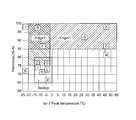
- FIG. 11 shows a matrix display of the results shown in Table 3 as tan ⁇ peak temperature (x axis) and hardness (y axis) for the edge portion.
- the hardness of the polyurethane constituting the backup portion is 71. However, it is preferable to select a polyurethane having a lower hardness than the polyurethane hardness of the edge portion. Therefore, the polyurethane hardness of the backup portion is appropriately 65 to 80. In Examples 8 to 11 where ether-based polyurethane was used for the edge portion, good printing could be performed up to 100,000 sheets. Even in the case of ether-based polyurethane, it is suitable that the edge portion is a polyurethane having a hardness higher than that of the backup portion. (2) Even if the edge hardness is 85 or less, Examples 3, 4, and 8 with a hardness of 76 show good results.
- the edge polyurethane has a hardness of 75 or more and a tan ⁇ peak temperature of ⁇ 20 ° C. to ⁇ 1 ° C.
- the polyurethane of the backup portion (base portion) preferably has a hardness of 75 or more. Therefore, considering the whole, the polyurethane forming the edge portion has (1) JIS-A hardness of 75 to 100 and tan ⁇ peak temperature of ⁇ 20 to ⁇ 1 ° C.
- the polyurethane forming the backup portion (base portion) has a JIS-A hardness of 65 to 80, with a peak temperature of -100 and a tan ⁇ peak temperature of ⁇ 20 to 60 ° C.
Landscapes
- Physics & Mathematics (AREA)
- General Physics & Mathematics (AREA)
- Cleaning In Electrography (AREA)
- Dry Development In Electrophotography (AREA)
- Electrophotography Configuration And Component (AREA)
- Electrostatic Charge, Transfer And Separation In Electrography (AREA)
- Casting Or Compression Moulding Of Plastics Or The Like (AREA)
- Polyurethanes Or Polyureas (AREA)
Abstract
Description
これらのブレードは、低温下、高速印字、球形トナー等、クリーニングが困難な環境下においては、クリーニング不良の問題を抱え、高温・高湿下ではブレードのスティックスリップが大きくなり、ブレード鳴き・カケ等の問題を生じ寿命を満足できないため、マシン制御等で問題を補う処置がとられていた。
従来、ブレードに好んで使用される一般的なポリウレタンゴムの物性のうち、tanδピーク温度は、-3~11℃であり、低温・低湿下でのクリーニング性能を重視すると、tanδピーク値は-3℃(低温)であるほど良好である。一方、高温・高湿下での耐久性は、tanδピーク値は、11℃(高温)であるほど、良好である。
そのため、単層ブレードの場合は、(個々のマシンでの取り扱いによるが、)低温クリーニング性能と耐久性のバランスを考えたブレードとなっていた。また、2層構造のブレードにおいては、例えばエッジ層に高温特性に優れるゴムを用い、バックアップ層に低温特性に優れるゴムを用いる設計がなされている。しかし、2層構造の設計では、期待するほどの機能分離ができず、単層ブレードと同様にマシン側での制御等で問題を補う処置がとられていた。
つまりは、低温、高速、球形トナーでクリーニングでき、かつ耐久性を兼ね備えたブレードは存在しなかった。
近年、OPC(有機光導電体)皮膜は、耐久性向上を狙いとして、その皮膜硬度が高硬度化する傾向にある。また、転写ベルト等においては、コストダウンを目的として、代替物の検討もなされ、その結果その表面が粗くなってしまうこともある。また、高速印刷を目的とし、OPCドラム等の像担持体の駆動速度も上昇傾向にある。これらは、全てブレードに対して高負荷をかけることになり、従来の仕様のブレード(例 JIS‐A硬度85度未満)では、ブレード反転等の問題を生じていた。これをブレードで解決するためには、ブレードそのものが持つ抵抗を下げること(低μ)が有効であり、望まれている。
特許文献1(特開2007-30385号公報)では、連続成型法を用いた手法であって、外周に成形溝及び内部に加熱装置を備えた成形ドラムを用いて、合成樹脂を成形用原料とするブレードの素材を連続成形する方法において、2種以上の異なる液状合成樹脂原料を別々に注型することにより、異種材料を組み合わせたブレード素材を製造する方法を提案した。
特許文献2(特開2007-163676号公報)では、注型法を用いた手法であって、割り金型の一方の金型に、部分層を形成する液状合成樹脂をビード状に注型した後、金型を組み、ベース層を形成する液状合成樹脂を注型して、加熱硬化してブレード素材を形成するブレードの製造方法を提案した。
特許文献3(特開2009-300551号公報)では、低温条件においても、トナーのすり抜けを防止することができるクリーニングブレードとして、材質が異なるエッジ部分とバックアップ層を備えた電子写真装置用のポリウレタン製のクリーニングブレードであって、エッジ部分の厚み×幅が0.03~0.4×0.03~4mmであるクリーニングブレードを提案した。
さらに、エッジ部やニップ部としてエーテル系ポリウレタンを使用したブレードの開発を研究した。
1.エッジ部分とバックアップ部分とが異なる組成から形成されるポリウレタン製ブレードにおいて、エッジ部分を形成するポリウレタンがバックアップ部分を形成するポリウレタンよりも高硬度であって、バックアップ部を形成するポリウレタンのJIS‐A硬度が65~80であり、エッジ部を形成するポリウレタンが、(1)JIS‐A硬度が、75~100かつtanδピーク温度が-20~-1℃、又は、(2)JIS‐A硬度が85~100かつtanδピーク温度が-20~60℃であることを、特徴とするブレード。
2.エッジ部分を形成するポリウレタンがエステル系のポリウレタンからなり、バックアップ部分を形成するポリウレタンがエーテル系ポリウレタンもしくはエステル系ポリウレタンであることを、特徴とする1.記載のブレード。
3.エッジ部分を形成するポリウレタンがエーテル系のポリウレタンからなり、バックアップ部分を形成するポリウレタンがエーテル系ポリウレタンであって、
バックアップ部を形成するポリウレタンのJIS‐A硬度が65~80であり、
エッジ部を形成するポリウレタンが、(1)JIS‐A硬度が、75~100かつtanδピーク温度が-20~60℃であることを、特徴とする1.記載のブレード。
4.エッジ部分を形成するエーテル系のポリウレタンが、ポリエーテルポリオールとしてポリテトラエチレングリコール、硬化剤として飽和脂肪酸アルカリ金属塩及び有機スズ化合物を用い、バックアップ部分を形成するポリウレタンがエーテル系ポリウレタンとして、ポリエーテルポリオールとしてポリテトラエチレングリコール、硬化剤の一部としてアミン系化合物を用いたことを特徴とする3.記載のブレード。
5.次の測定条件にて、トルクが0.8kgf/cm以下であることを特徴とする1.~4.のいずれかに記載のブレード。
測定条件
ブレードをOPCドラムに接線方向に侵入させ、侵入方向に対向する
方向にOPCドラムを線速200mm/sになるように回転させ、侵
入量が1.2mmのときOPCドラムの回転軸の負荷トルクとして計
測される値
6.エッジ部硬度が80度以上のポリウレタンには、硬化触媒に飽和脂肪酸アルカリ金属塩が使用されていることを特徴とする1.~5.のいずれかに記載のブレード。
7.エッジ部分がバックアップ層とは異なる色であることを特徴とする1.~6.のいずれかに記載のブレード。
8.エッジ部分の厚み×幅が0.03~0.4×0.03~4.0mmであることを特徴とする1.~7.のいずれかに記載のブレード。
9.ブレードが、クリーニングブレード、現像ブレード又は帯電ブレードであることを特徴とする1.~8.のいずれかに記載のブレード。
10.エッジ部分とバックアップ部分とが異なる組成から形成されるポリウレタン製ブレードにおいて、エッジ部分を形成するポリウレタンがバックアップ部分を形成するポリウレタンよりも高硬度であって、バックアップ部を形成するポリウレタンのJIS‐A硬度が65~80であり、エッジ部を形成するポリウレタンが、(1)JIS‐A硬度が、75~100かつtanδピーク温度が-20~-1℃、又は、(2)JIS‐A硬度が85~100かつtanδピーク温度が-20~60℃であるブレードを製造する方法であって、成形溝を外周に備え、内部に加熱装置を備えた成形ドラムであって、該成形ドラムの外周に沿って、成形溝に合成樹脂供給手段、成形ドラムの成形溝を覆いながら成形ドラムの回転に同期して回走するエンドレスベルトを順次配置し、成形溝に供給した合成樹脂原料をエンドレスベルトと成形溝から形成される成形空間によって、所定の幅と厚さを有する帯状のブレード素材を成形ドラムの回転に従い製造する方法を用いたブレードの製法であって、前記エッジ部を形成するポリウレタン原料を先に円筒状の金型に流し込み金型を回転しながら硬化させて、半硬化した後、バックアップ部を形成するポリウレタン原料を流しこみ回転させながら硬化させて帯状のブレード素材を取り出し、長さを定寸にカットした後に、エッジ部を含む端縁をカットして成型することを特徴とするブレードの製造方法。
11.エッジ部分を形成するポリウレタンがエステル系のポリウレタンからなり、バックアップ部分を形成するポリウレタンがエーテル系ポリウレタンもしくはエステル系ポリウレタンであることを特徴とする請求項10記載のブレードの製造方法。
12.エッジ部分を形成するポリウレタンがエーテル系のポリウレタンからなり、バックアップ部分を形成するポリウレタンがエーテル系ポリウレタンであって、バックアップ部を形成するポリウレタンのJIS‐A硬度が65~80であり、エッジ部を形成するポリウレタンが、(1)JIS‐A硬度が、75~100かつtanδピーク温度が-20~60℃であることを、特徴とする10.記載のブレードの製造方法。
13.エッジ部分とバックアップ部分とが異なる組成から形成されるポリウレタン製ブレードにおいて、エッジ部分を形成するポリウレタンがエステル系のポリウレタンからなり、バックアップ部分を形成するポリウレタンがエーテル系ポリウレタンもしくはエステル系ポリウレタンであって、バックアップ部を形成するポリウレタンのJIS‐A硬度が、65~80であり、エッジ部を形成するポリウレタンが、(1)JIS‐A硬度が75~100かつtanδピーク温度が-20~-1℃、又は、(2)JIS‐A硬度が85~100かつtanδピーク温度が-20~60℃であるブレードを製造する方法であって、成形溝を外周に備え、内部に加熱装置を備えた成形ドラムであって、該成形ドラムの外周に沿って、成形溝に合成樹脂供給手段、成形ドラムの成形溝を覆いながら成形ドラムの回転に同期して回走するエンドレスベルトを順次配置し、成形溝に供給した合成樹脂原料をエンドレスベルトと成形溝から形成される成形空間によって、所定の幅と厚さを有する帯状のブレード素材を成形ドラムの回転に従い製造する方法を用いたブレードの製法であって、前記エッジ部を形成するポリウレタン原料を先に円筒状の金型に流し込み金型を回転しながら硬化させて、半硬化した後、バックアップ部を形成するポリウレタン原料を流しこみ回転させながら硬化させて帯状のブレード素材を取り出し、長さを定寸にカットした後に、エッジ部を含む端縁をカットして成型することを特徴とするブレードの製造方法。
14.エッジ部分とバックアップ部分とが異なる組成から形成されるポリウレタン製ブレードにおいて、エッジ部分を形成するポリウレタンがエステル系のポリウレタンからなり、バックアップ部分を形成するポリウレタンがエーテル系ポリウレタンもしくはエステル系ポリウレタンであって、バックアップ部を形成するポリウレタンのJIS‐A硬度が65~80であり、エッジ部を形成するポリウレタンが、(1)JIS‐A硬度が75~100かつtanδピーク温度が-20~-1℃、又は、(2)JIS‐A硬度が85~100かつtanδピーク温度が-20~60℃であるブレードを製造する方法であって、型部材を型組して形成されるキャビティー内へ液状のポリウレタン原料を注型し、重合硬化後脱型して製造する割型成型法を用いたブレードの製造方法において、型組みする前に一方の割型の壁面に筋状にエッジ部形成する液状のポリウレタン原料を塗布し、半硬化させた後に型組みし、バックアップ層を形成するポリウレタン原料を注入し、硬化させて脱型してブレード素材を得、該ブレード素材の端縁をカットしてエッジ部を成型することを特徴とするブレードの製造方法。
15.エッジ部分とバックアップ部分とが異なる組成から形成されるポリウレタン製ブレードにおいて、エッジ部分を形成するポリウレタンがエステル系のポリウレタンからなり、バックアップ部分を形成するポリウレタンがエーテル系ポリウレタンもしくはエステル系ポリウレタンであって、バックアップ部を形成するポリウレタンのJIS‐A硬度が65~80であり、エッジ部を形成するポリウレタンが、(1)JIS‐A硬度が、75~100かつtanδピーク温度が-20~-1℃、又は、(2)JIS‐A硬度が85~100かつtanδピーク温度が-20~60℃であるブレードを製造する方法であって、型部材を型組して形成されるキャビティー内へ液状のポリウレタン原料を注型し、重合硬化後脱型して製造する割型成型法を用いたブレードの製造方法において、前記エッジ部を含むブレードの先端を形成する側を底部側とする成型型であって、該成型型を鉛直方向から傾斜させた状態で、エッジ部形成する液状のポリウレタン原料を注型し、その後、鉛直に戻した状態でバックアップ層を形成するポリウレタン原料を注入して、硬化させた後脱型することを特徴とするブレードの製造方法。
16.エッジ部分を形成するポリウレタン原料をエステル系ポリウレタン原料、バックアップ層を形成するポリウレタン原料をエーテル系ポリウレタン原料とすることを特徴とする10.~15.のいずれかに記載のブレードの製造方法。
17.エッジ部分を形成するポリウレタンとして、バックアップ層を形成するポリウレタンとは異なる色に着色したポリウレタンを用いることを特徴とする10.~16.のいずれかに記載のブレードの製造方法。
18.ブレードが、クリーニングブレード、現像ブレード又は帯電ブレードであることを特徴とする10.~17.のいずれかに記載のブレードの製造方法。
本発明は、従来よりも高圧で接した場合でも、低摩擦を実現できるブレードを提供できた。本発明が実現したブレードは低いμを保有し、その結果、装置の消費電力の低減に寄与することができ、像担持体の寿命を延ばすことができ、装置の超寿命化を図ることができる。
本発明のブレードを用いることにより、像担持体の皮膜硬度を向上、また、印刷速度をアップした場合でも、ブレード反転やブレード鳴きが生ずることがない。また、像担持体の代用品である低コストで表面の粗さが低下した代替品のクリーニング性能も満足できる。低摩擦化は、駆動時の像担持体にかかる負荷を低減することができ、消費電力の低減につながり、マシンの超寿命化につながる。
特に、硬化触媒として飽和脂肪酸アルカリ金属塩を用いることにより、エッジ部に適した高硬度ポリウレタンを実現することができた。この触媒を用いることにより、JIS‐A硬度80度以上、特に、100度のポリウレタンを実現することができる。
バックアップ部と異なる着色をしたエッジ部を形成することにより、エッジ部の場所が検知しやすくなり、検査や組み付け作業を向上させることができる。好ましいエッジ部の範囲は厚み×幅が0.03~0.4×0.03~4mmであり、両者とも透明とすると、見分けることが困難であるが、異なる着色がされていると、ブレード製造工程のみならず電子写真装置への組み付け及びその後の確認も容易であり、ミスの発生を抑制することができる。ポリウレタンとして、熱硬化性ポリウレタンが適しており、エッジ部分のポリウレタンとしてエステル系ポリウレタン、バックアップ層を形成するポリウレタンとしてエステル系ポリウレタンとエーテル系ポリウレタンが適している。特にエーテル系が適している。本発明の、ブレードの製造方法として、成形ドラムを用いた連続成形方法、注型型を用いた個別成形方法を提供する。また、注型型を用いる場合、傾斜させた状態でエッジ部形成用の液状ウレタンを注入することにより、断面三角形状のエッジ部を形成することができ、半硬化後直立状態に戻して、バックアップ部分を形成するポリウレタン原料を注型することにより、効率よくエッジ部を形成できる注型型による成形方法を提供することができる。
さらに、エッジ部あるいはニップ部にもエーテル系ポリウレタンを使用したブレードを提供できた。特に、成形ドラムを用いた連続成形方法を用いることにより、エーテル系ポリウレタンをエッジ部あるいはニップ部に用いたブレードを開発することができた。外周に成形用溝を備えた成形ドラムを用いて、エッジ部をJIS‐A硬度77~78度のエーテル系ポリウレタンにおいて、この永久歪み0.1mm以内を達成した。
2 ベース層
3 ブレード
4 支持部材
5 ブレード断面
10 外部加熱装置
11 第一注型機ミキシングベルト
12 第二注型機ミキシングベルト
13 成形ドラム
14 エンドレスベルト
15 回転軸
16 予熱ロール
17 ガイドロール
18 テンションロール
19 冷却ロール
20 冷却コンベヤ
21 冷却装置
22 弛み検知器
23 送りロール
24 裁断装置
25 コンベア
26 上側センサー
27 下側センサー
101 帯状ブレード素材
103 定尺寸法ブレード部材
108 吐出ヘッド
110 金型
110a、110b 分割金型
111 分割金型に注型する装置
112 スライド板
113 ベース板
114 側壁
115 傾斜側壁
116 型締め部材
210 金型
201 液状ポリウレタン樹脂
202 液状ポリウレタン
204 支持部材
従来のブレード、例えば単層ブレードの場合、硬度を上げると、その弾性を失ってしまう。あるいは、複層ブレードとして、提案されるように2層構造にして、エッジ層の硬度を上げる方法も存在するが、十分にゴムの弾性を保持することができず、ブレード材として必要なエッジ先端部の、スティックスリップが充分ではなく、クリーニングブレードとして機能しない。
しかし、本発明は、エッジ部のみを極端に高硬度にした場合、大部分のバックアップ部のゴム物性に支配され、十分にゴムの弾性を保持することができるようになる。つまり、適度なステッィクスリップを行うことができ、ブレードとしての十分な機能を発揮することができる。
さらに、エッジ部を高硬度(JIS‐Aで85度以上)にすることにより、そのμは、従来一般的なブレードが保有するμを20%以上低減でき、この場合、tanδピーク温度の値は、制約にならない。一方で、μを低下させるもう一つの手段は、ゴムが持つその弾性率をアップさせることが有効であり、tanδピーク温度が、-15~-3℃の範囲においては、JIS‐A硬度が75度以上保有すれば、その効果を得ることができる。
そして、このように高硬度を容易に製作するには、速硬化性の触媒(酢酸Na)が有用である。酢酸Naを適量使用することで、製作されるウレタン部にヌレート結合を多数生じ、これにより、高硬度が発現することができる。
エッジ部分を形成するポリウレタンがエーテル系のポリウレタンが、ポリエーテルポリオールとしてポリテトラメチレングリコール(PTMG)、硬化剤の一部として飽和脂肪酸アルカリ金属塩及び有機スズ化合物を用い、バックアップ部分を形成するポリウレタンがエーテル系ポリウレタンとして、ポリエーテルポリオールとしてポリテトラメチレングリコール(PTMG)、硬化剤の一部としてアミン系化合物を用いることが好ましい。
本発明では、この永久歪みを、0.1mm以内に抑えることができた。特に、外周に成形用溝を備えた成形ドラムを用いて、エッジ部をJIS‐A硬度77~78度のエーテル系ポリウレタンにおいて、この永久歪み0.1mm以内を達成した。
永久歪み試験方法については、概略を図13に示す。
本願発明のブレードの断面図を図1に示す。トナーを掻き取るために像担持体等の表面に圧着当接するエッジを中心に、エッジ部分とベースとなるバックアップ部分が異なるポリウレタンで形成されている。
エッジ部分を形成するポリウレタンがバックアップ部分を形成するポリウレタンよりも高硬度である。バックアップ部を形成するポリウレタンのJIS‐A硬度が65~80であり、エッジ部を形成するポリウレタンが、(1)JIS‐A硬度が、75~100かつtanδピーク温度が-20~-1℃、又は、(2)JIS‐A硬度が85~100かつtanδピーク温度が-20~60℃であるブレードである。
エッジ部分は、エッジ部分を形成するポリウレタンがエステル系のポリウレタンであり、(1)JIS‐A硬度が、75~100かつtanδピーク温度が-20~-3℃、又は、(2)JIS‐A硬度が85~100かつtanδピーク温度が-3~60℃である。エッジ部分の大きさは、厚み×幅が0.03~0.4×0.03~4mmが好ましい。さらには、厚み方向において、少なくとも30μm以上であって、0.4mm以内、望ましくは0.2mm以内、さらに望ましくは0.1mm以内であること、幅方向において、少なくとも30μm以上であって、4mm以内、望ましくは2mm以内、さらに望ましくは0.5mm以内とするものである。エッジ部分は、バックアップ部分と異なる色に着色すると識別ができ、トリミングや検査や組み付け作業が容易となる。エッジ部用のJIS‐A硬度80度以上の高硬度ポリウレタンの形成には、飽和脂肪酸アルカリ金属塩が硬化触媒として有効である。特に、飽和脂肪酸アルカリ金属塩(酢酸Na)が適している。他の触媒(有機スズ化合物、3級アミン化合物)の併用も可能である。
本発明のブレードは、支持部材に取り付けて、クリーニングブレード、現像ブレード又は帯電ブレードとして利用することができる。電子写真装置に使用される感光ドラム、転写ベルト、中間転写体等の像担持体に残留するトナーを除去するためのクリーニングブレード、現像プロセスに用いられる現像ブレード、さらに、像担持体に電荷を与える帯電ブレードである。
例えば、図2に示すエッジ部分の部分層1とバックアップ層となるベース層2からなるポリウレタン製ブレード3を支持部材4に接着して構成される。本発明では、基本的にエッジ部にエステル系ポリウレタンを用い、ベース部にはエーテル系ポリウレタンを用いることが好ましい。あるいは、特殊が組み合わせのエーテル系ポリウレタンを用いることができる。
JIS‐A硬度65~100は、IRHD硬度と次の相関関係(図12参照)にある。
JIS‐A硬度= 0.9052 ×(IRHD硬度)+ 6.5661
本発明に用いられるブレードは、熱硬化性ポリウレタン樹脂製が適している。
ウレタンの形成材料としては、ポリイソシアネート及びポリオールを含有するポリウレタン組成物が用いられる。
ポリオール成分として、エッジ部あるいはニップ部を含む層はエステル系ポリウレタンを用い、エッジ部やニップ部を含む層以外のベース部はエーテル系ポリウレタンの組み合わせを用いる。あるいは、エッジ部あるいはニップ部及びベース部には、エーテル系ポリウレタンを選択的に用いることができる。
本発明に用いられるポリウレタン原料は、非溶剤型の熱硬化性が望ましい。例えば、本出願人が、先に出願した特願2007-18162号に開示した、エステル系ポリウレタン、エーテル系ポリウレタンを用いることができる。エッジ部分用ポリウレタン樹脂に着色剤を添加してバックアップ層とは異なる色とすると、エッジ部分の大きさが明瞭に識別できる。ポリウレタンを硬化させた後にエッジの大きさをトリミングして形成するのが容易になる。
あるいは、エッジ部分及びバックアップ部を形成するポリウレタンがエーテル系ポリウレタンの場合は、エッジ部分を形成するポリウレタンがエーテル系のポリウレタンが、ポリエーテルポリオールとしてポリテトラメチレングリコール(PTMG)、硬化剤として飽和脂肪酸アルカリ金属塩及び有機スズ化合物を用い、バックアップ部分を形成するポリウレタンがエーテル系ポリウレタンとして、ポリエーテルポリオールとしてポリテトラメチレングリコール(PTMG)、硬化剤の一部としてアミン系化合物を用いることが適している。
エッジ層にはエステル系ポリウレタンが適している。ポリエステルジオール、ポリエステルトリオール等のポリエステルポリオールが適している。(a)JIS‐A硬度が、75~100かつtanδピーク温度が-20~-3℃、又は、(b)JIS‐A硬度が85~100かつtanδピーク温度が-3~60℃である。エステル系ポリウレタンをバックアップ層として用いることもできるが、エッジ層よりも低硬度とする。
ポリエステルポリオールとしては、多塩基性有機酸とポリオールとから製造される。ε-カプロラクタムの開環重合から得られるポリカプロラクトンジオール等のポリカプロラクトンポリオールも使用できる。
エッジ部硬度が80度以上のポリウレタンについては、硬化触媒に飽和脂肪酸アルカリ金属塩(酢酸Na)を使用する。また、他の触媒(有機スズ化合物、3級アミン化合物)の併用も可能である。
多塩基性有機酸としては、特に限定するものではなく、シュウ酸、コハク酸、グルタル酸、アジピン酸、ピメリン酸、スベリン酸、アゼライン酸、セバシン酸、イソセバシン酸等の飽和脂肪酸や、マレイン酸、フマル酸等の不飽和脂肪酸や、フタル酸、イソフタル酸、テレフタル酸等の芳香族酸等のジカルボン酸があげられる。また、無水マレイン酸、無水フタル酸等の酸無水物や、テレフタル酸ジメチル等のジアルキルエステル等を用いることもできる。さらに、不飽和脂肪酸の二量化によって得られる、ダイマー酸を用いることもできる。これらは単独でもしくは2種以上併せて用いられる。
エッジ部分及びバックアップ部を形成するポリウレタンがエーテル系ポリウレタンの場合は、エッジ部分を形成するエーテル系のポリウレタンが、ポリエーテルポリオールとしてポリテトラメチレングリコール(PTMG)、硬化剤の一部として飽和脂肪酸アルカリ金属塩及び有機スズ化合物を用い、バックアップ部分を形成するエーテル系ポリウレタンとして、ポリエーテルポリオールとしてポリテトラメチレングリコール(PTMG)、硬化剤の一部としてアミン系化合物を用いることが適している。
ポリイソシアネートとしては、特に限定するものではなく、例えば、4,4’-ジフェニルメタンジイソシアネート(MDI)、2,4-トリレンジイソシアネート(2,4-TDI)、2,6-トリレンジイソシアネート(2,6-TDI)、3,3′-ビトリレン-4,4’-ジイソシアネート、3,3’-ジメチルジフェニルメタン-4,4’-ジイソシアネート、2,4-トリレンジイソシアネートウレチジンジオン(2,4-TDIの二量体)、1,5-ナフチレンジイソシアネート、メタフェニレンジイソシアネート、ヘキサメチレンジイソシアネート、イソホロンジイソシアネート、4,4’-ジシクロヘキシルメタンジイソシアネート(水添MDI)、カルボジイミド変性MDI、オルトトルイジンジイソシアネート、キシレンジイソシアネート、パラフェニレンジイソシアネート、リジンジイソシアネートメチルエステル等のジイソシアネート、トリフェニルメタン-4,4’,4’’-トリイソシアネート等のトリイソシアネート、ポリメリックMDI等があげられる。これらは単独でもしくは2種以上併せて用いられる。なかでも、耐摩耗性の観点から、MDIが好ましい。
ポリウレタン組成物には、上記ポリイソシアネート及びポリオール以外に、鎖延長剤、界面活性剤、難燃剤、着色剤、充填剤、可塑剤、安定剤、触媒等通常用いられている剤を配合することができる。
エッジ部硬度が80度以上のポリウレタンについては、硬化触媒に飽和脂肪酸アルカリ金属塩(酢酸Na)を使用する。
上記三級アミンとしては、トリエチルアミン等のトリアルキルアミンや、N,N,N’,N’-テトラメチル-1,3-ブタンジアミン等のテトラアルキルジアミンや、ジメチルエタノールアミン等のアミノアルコールや、エトキシル化アミンや、エトキシル化ジアミンや、ビス(ジエチルエタノールアミン)アジペート等のエステルアミンや、トリエチレンジアミンや、N,N-ジメチルシクロヘキシルアミン等のシクロヘキシルアミン誘導体や、N-メチルモルホリン、N-(2-ヒドロキシプロピル)-ジメチルモルホリン等のモルホリン誘導体や、N,N’-ジエチル-2-メチルピペラジン、N,N’-ビス-(2-ヒドロキシプロピル)-2-メチルピペラジン等のピペラジン誘導体等があげられる。
上記有機錫化合物としては、ジブチル錫ジラウレート、ジブチル錫ジ(2-エチルヘキソエート)等のジアルキル錫化合物があげられる。また、2-エチルカプロン酸第1錫、オレイン酸第1錫等があげられる。
エッジ部又はニップ部用のポリウレタンについては、硬化触媒に飽和脂肪酸アルカリ金属塩(酢酸Na)と有機錫化合物を組み合わせて使用することが好ましい。
本発明で用いられる合成樹脂は、主に熱硬化性のポリウレタン樹脂である。特に、非溶剤型の2液性の熱硬化性ポリウレタンが適している。外周成型溝回転ドラムによる連続成型法は、注型から取り出しまでの時間が成形ドラムの一回転以内であり、30~60秒程度で取り出し可能な程度に重合固化している必要がある。このような条件を満たすイソシアネートとポリオール、架橋剤、触媒を選定し設計する。取り出した後の工程において、2次架橋、熟成工程を施すことができる。割型を用いる場合も、エッジ部やニップ部となるエステル系ポリウレタンの初期硬化時間を短くすることが望ましい。
潤滑剤の例としては、ポリ四フッ化エチレン、窒化ホウ素、グラファイト、二硫化モリブデン、ポリジメチルシロキサン等のシリコン化合物がある。
導電性付与物質としては、特に限定されるものではないが、ケッチェンブラック、アセチレンブラック、ファーネスブラック等のカーボンブラックや、グラファイト、金属フィラー、金属酸化物ウィスカー等の電子伝導性物質、金属石鹸、過塩素酸塩等のイオン伝導性物質等を単独で、もしくは2種以上の物質を組合わせて使用することができ、現像ブレードや帯電ブレードに適用される。
研磨粒子は、感光体等、当接する相手材の表面をリフレッシュする目的で使用されるブレードに適用される。
ウレタンプレポリマーの液状物及び架橋剤との液状物のうち少なくとも一方に混合される高分子量ポリオールの成分が数平均分子量1000~3000の2官能ポリオールと、数平均分子量92~980の3官能ポリオールとを平均官能基数が2.02~2.20となるポリオールにイソシアネート基の含量が5~20%となる量のジイソシアネート化合物を混合してプレポリマーを調製し、そのプレポリマーに、OH基/NCO基の当量比が0.30~1.07となる量の架橋剤とを40~70℃において混合してポリウレタン液状物(未硬化ポリウレタン組成物)を調製する。
エッジ部のポリウレタン層とベース部層のポリウレタン層の2層に形成する方法は、(a)外周に溝を形成した回転成型ドラムを利用して連続成型する方法、(b)割型による個別に成形する方法を利用することができる。割型を使用する成形方法では、型を組む前に一方の型にエッジ部分形成用ポリウレタン原料をビード状に塗布した後に型組みする方法と型組した後に傾斜させてエッジ形成用のコーナー部にエッジ用ポリウレタン原料を注入する方法がある。
この成型手段は、本出願人が先に提案した特開2007-30385号公報に開示した手段を利用することができる。ブレードに使用されている合成樹脂製の弾性ゴムからなるテープの幅と同一かそれよりやや大きい幅を有する合成樹脂製のテープを連続して製造し、その長尺テープを定寸にカットし、金属製の支持体の一側縁に接合して現像ブレード、クリーニングブレード等に仕上げる技術を基本製法とする。あるいは、特開2009-51037号公報図5に本出願人が開示したような幅広のブレード素材を2分割する手段を利用することができる。
この製法に用いる基本的な製造手段は、外周に成形溝を設けた成形ドラムを、水平軸を中心に回転させつつ、ポリウレタンの液状原料を頂点付近から成形溝に連続注型し、成形ドラムの回転動作中に重合させて、注型箇所より前の位置でテープ状となったポリウレタン製の連続成型物を剥離して、成形溝から取り出し、後工程に供給するものを用いるものである。テープ状の成型物が連続して産出されるので、後工程では、一本の定尺にカット、エッジ形成カット、金属支持体との接合と一連の作業を連続して実施でき、稼働に無駄がなく生産性が高い。
先行するポリウレタンを成形溝のコーナー部に注型した場合は、エッジ部に異種材料を設けたブレード素材を製造することができる。
中間部に注型した場合は、ブレード素材の中間に異種材料を設けることができる。例えば、図6に示すように、2倍の幅のブレード素材を連続成形して、中央部にエッジ部を形成した場合には、中央で分割することにより、エッジ部の形成と同時に2枚のブレードを得ることができる。
図3に示すように、弾性ゴム部材であるブレード素材の製造装置は、外周に成型用溝が形成された成形ドラム13、樹脂を供給する供給口する第1注型機ミキシングヘッド11、第2注型機ミキシングヘッド12、スチール製の鏡面を備えたエンドレスベルト14、冷却用コンベア20、裁断装置24、搬出用のコンベア25等から構成される。
エッジ部に異種材料層を設けたブレード素材は、エッジ部を当接するクリーニングブレード等に適している。また、異種材料を組み合わせることにより、弾性ゴムの物性値をコントロールすることができるので、高温域や低温域等の温度変化適性、あるいは、摩耗耐性等を向上させることができる。また、この成形ドラムを用いたポリウレタン製合成樹脂シートの連続成形法は、本出願人が既に提案した各製法、構成要素を使用できるものである。
この手法においては、樹脂注型後数十秒以内(例えば、30~60秒程度)に成形溝から取り出されること、成形のために加圧されないこと、重合硬化は回転する成型ドラムの下半部が中心であること、成形溝からの引き剥がし角度を小さくすることができる等の成形条件であるので、成形溝底面からの剥離が比較的容易であり、必ずしも離型剤を使用する必要がない。トナーが微細化やカラー化することによって、離型剤が悪影響となることがあり、本発明の一形態として、離型剤を使用しない場合は、このような不都合も生じない。また、離型剤を用いる必要がないことは、他の表面処理剤を作用させることもでき、積極的に表面改質に利用することも可能である。
図3に示される第1注型のA点からエンドレスベルト14が被覆するF点までの成形過程を模式的に説明する。この図示の例では、弾性ゴム部材の面の中間部に筋状に部分層1を形成する例を示している。また、注型された液状ポリウレタン樹脂の硬化状態を斜線で示し、未硬化の部分は白抜きに標記している。ただし、この硬化進行状況はイメージ的表示であって、加熱されている成型溝の底面や壁面に接した部分から硬化が進行し、エンドレスベルトも加熱されているので、接触によって溝部開放側も硬化が促進されるというイメージである。
まず、A点では、成形溝内に第1注型口11aから部分層1に相当するポリウレタ樹脂液を注型する。この例では、筋状になるような一定量を連続して供給する。重合に適した温度に加温された成形溝底面に接した樹脂は重合が始まり、B点では半硬化している状態を示している。C点においてベース層2を形成する樹脂を第2注型口12aから残りの成形溝断面を充填する量を連続して供給する。D点では成形溝底面や壁面の高温部に接触した部分から硬化が進行している状態を現している。エンドレスベルトが接触する直前のE点では、成形溝開放部表面側が流動状態を残し、下流側への流れ込みが生ずるため、やや盛り上がった状態を示している。F点では、エンドレスベルトの鏡面と接触し、予熱で高温とされたベルトと接触して、表面側も硬化が進行することとなる。なお、F点では全体に斜線が入っているが、重合硬化が完全に終了したことを意味するものではない。
このF点から取り出し位置(図3に示されるG点)までの間にさらに重合が進行し、シート状に引出可能とされる。
なお、B点付近やD点付近に外部加熱装置を配置すると、表面側の重合を促進することができる。また、G点の直前に冷風送風装置等の冷却装置を配置すると、成形溝からの剥離性を向上させることができる。また、離型剤や表面処理剤等を連続して供給する場合は、G点とA点の間に配置することができる。
このようにして得られた連続したポリウレタン弾性ゴム部材を定寸長にカットし、さらに、部分層1がエッジになるように所定の幅に切断成形することにより、所望のエッジの大きさを備えたブレードを製造することができる。エッジ部とベース部が異なる色に着色されていると切断位置の決定が容易である。
図5は、支持部材4にブレードを接合した状態を示しており、部分層1は断面弧状に形成されるので、エッジの大きさを考慮して、切断位置を決定するイメージを示している。図示は、部分層の1/2の幅でカットすることを表している。
割型成型法は、1枚のポリウレタン製の弾性ブレードの大きさに相当するキャビティーを成型する2枚の型部材をあわせて、キャビティー内へ液状のポリウレタン原料を注型し、重合硬化後脱型して製造するものである。型組みする前に一方の割型の壁面に筋状にエッジ部を形成する液状のエステル系ポリウレタン原料を塗布し、半硬化させた後に型組みして、ベース部を形成するエーテル系ポリウレタン原料を注入して、硬化させて脱型して部分2層を形成したブレード素材を得る。
この割型による部分2層の成型方法は、本出願人が出願した特開2007-163676号公報に開示した手段を用いることができる。
即ち、次のとおりである。
部分層に相当する位置に熱硬化性樹脂である液状のポリウレタン樹脂を吐出するヘッドを移動させるか、あるいは金型を移動させることにより熱硬化性樹脂をビード状に塗布するように注型した後、割り金型を組み、ベースとなる熱硬化性樹脂を注型して加熱炉で一体成形する。一体成形されたブレード素材は、割り金型を解体して取り出して所定のサイズに裁断されてブレードとして用いられる。金型を組むときに支持体の一部をキャビティー内部にセットして、ベース形成用樹脂を注型すると支持体とブレードゴム体を一体的に接合できる。
図7に割金型構造の概略を断面図として示す。
金型110は、左右の分割金型110a,110bから構成される。分割金型110a,110bの中間には支持部材となる芯金AAを挟持する突出部材が形成されている。この分割型110a,110bは、ベース板113と該ベース板113の左右に立設された側壁114と傾斜側壁115の間に配置し、該傾斜側壁115側に楔状に型締め部材116を押し込むことにより、締め付けられて型組されるものである。両分割金型110a,110bの間に形成された空間にベースとなる合成樹脂を注型して、ブレードが成型される。
図7に示したものは、芯金AAを配置して、樹脂の加熱成型と芯金との接合を同時に行う例を示している。芯金AAを配置せずに樹脂を硬化したブレード素材を成型し、その後支持部材を接合して、ブレードを製造することもできる。
図8に分割金型の一方(110a又は110b)に分割層を形成する樹脂を吐出ヘッド108から長手方向、ビード状に吐出する状態を示す。部分層の注型手段は、例えば、吐出ヘッドを移動させる方法と分割金型を移動させる2つの方法を採用することができる。
図9に金型を用いたエッジ部形成法の別法を示す。
金型210のキャビティー底面を傾けて、エッジ部分形成用の液状ポリウレタン樹脂201を注入して半硬化させた後、底面を水平に戻して、バックアップ部分形成用の液状ポリウレタン202を注入して、硬化させて、脱型してブレードを成形する方法である。
バックアップ部分形成用の液状ポリウレタンを注型する前に、支持部材204をセットすると、支持部材と一体化したブレードを成形することができる。
図示の例では、直立した状態でバックアップ部を注型する例を示しているが、金型を密閉した状態で注型する場合は、エッジ部の形成後に注型する姿勢はこれの限られるものではない。
ポリウレタン製弾性ゴム部材:厚さ2.0mm、幅12.3mm、長さ3
26mm
エッジ部の大きさ:表2に示す大きさとした
金属製支持体:厚さ1.2mmの鋼板
接着処理:ダイマー酸ベースのホットメルト接着剤使用
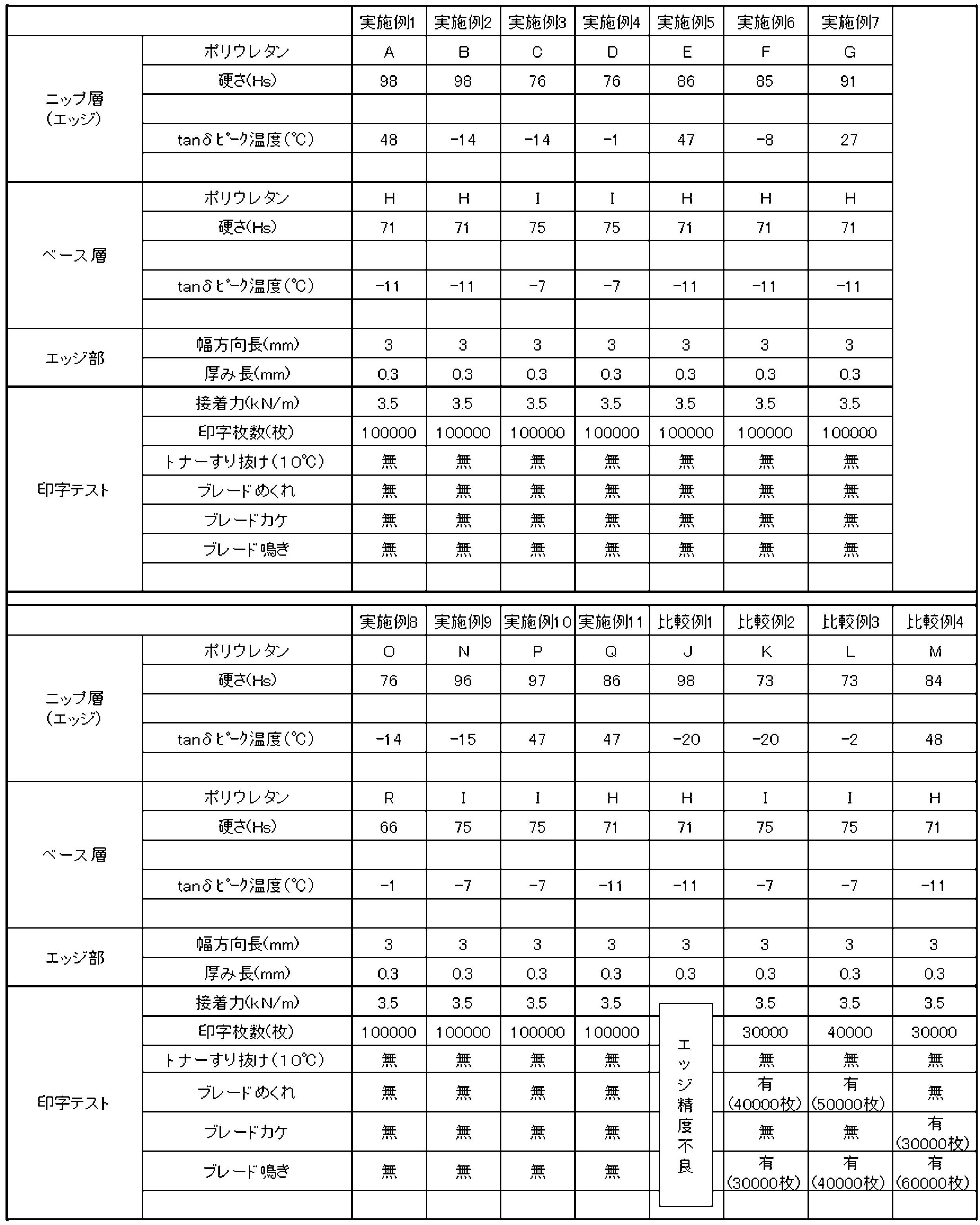
エッジ層あるいはベース層に用いたエステル系ウレタン、エーテル系ウレタンの配合は、表1に示したとおりである。表3にウレタンの組み合わせ及び評価を示す。

評価機:市販のプリンターを使用
(株)リコー CX9800
評価パターン
・ 耐久評価(23℃×53%)で通紙10万枚
画像パターンは、エリアカバー5%プリントで実施
トナーすり抜けによるクリーニング不良の発生有無、トナー融着有無
、ブレード磨耗深さの測定で実施
・ クリーニング性能評価(10℃×15%)で実施
画像パターンは、15mm幅×250mm(×3箇所)の黒帯画像を
50枚出力後、感光体上のすり抜けたトナーをメンディングテープで
採取し、すり抜けている幅を測定(すり抜け幅の少ないものが性能が
よい)
ブレードの鳴きは、ブレードにかかるストレス指数で評価することが可能である。下記の評価では、そのストレス指数をローラー軸上に生じるトルクを計測し評価する。
ブレードを侵入量の変量できる治具上に取り付け、相手材は、市販のOPCドラムとする。
評価試験機の概要を図10に示す。
図10(a)に示す形状のブレードを用いて、図10(b)に示す試験機を用いて計測した。
ブレードを侵入量の変量できる治具上に取り付け、市販のOPCドラム(リコーCX9800のドラムを使用)に接線方向に侵入させ、侵入方向に対向する方向にOPCドラムを線速200mm/sになるように回転させてOPCドラムの軸上で生じたトルクを計測する。
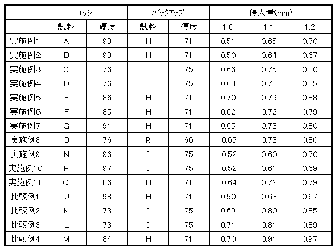
クリーニングブレードの通常の使用では、侵入量を1.0mmとし、そのマージンとして、+0.1mmまでは鳴きを生じないことが必要となる。すなわち、侵入量が1.1mmでも鳴きを生じないことが必要であり、侵入量のマージンが増える程、その性能はよいと、判断できる。
この試験結果から、エッジ部が高硬度になると低トルクとを実現できることが分かる。エッジ硬度を85以上に設計すると侵入量が1.2mm以上でもトルクを0.8kgf/cm以下を実現できることを知見できた。
事前に行った予備試験において、単層シートでの走行試験では、高硬度単層(85度以上)は、金具とゴムの接着部でゴムが大きく変形してしまう。そのため、経時のプリント中に印字不良を生じる。(トナーすり抜け)これを抑制するために、バックアップに永久変形しにくい低硬度(エッジ部と比較して)のものを採用することとする。
トルク計測試験の結果から、概ねエッジ硬度が高くなるとμが低下する傾向があることが分かる。トルク値0.8kgf/cm以上において、ブレードに鳴きが生ずることが知見され、侵入量1.0mmでは、全試料とも0.8以下であるが、標準侵入量1.1mmでは、エッジ部の硬度76以上において、0.8以下であり、安全をみた1.2mm侵入量では実施例5のデータを除き、エッジ部の硬度85以上において0.8kgf/cm以下のトルク値を実現できることがわかった。
特に、エッジ部にエーテル系ポリウレタンを使用した実施例8~11においても、トルク値0.8kgf/cm以上において、ブレードに鳴きが生ずることが知見され、侵入量1.0mmでは、全試料とも0.8以下であるが、安全をみた標準侵入量1.2mm侵入量でも0.8kgf/cm以下のトルク値を実現できた。
(1)硬度に着目すると、実施例5、6に示されるエッジ硬度85、86以上及び実施例1、2に示されるエッジ硬度98において良好な結果を示している。エッジ硬度が84である比較例4では、印字試験中にブレードの欠け及び鳴きが発生し、印字テスト30000枚で不良となっている。硬度85以上で良好な印字試験結果を示した、実施例1、2、5、6、7に関するtanδピーク温度は、-14~48℃である。比較例1ではエッジ成形の精度が不良であることを参照すると、tanδピーク温度は、-20℃以上で有効と想定され、上限値は60℃程度まで有効であると想定される。バックアップ部を構成するポリウレタンの硬度は、71を採用したが、エッジ部のポリウレタン硬度よりも低いポリウレタンを選択することが好ましいので、バックアップ部のポリウレタン硬度は65~80が適切である。
エッジ部にエーテル系ポリウレタンを使用した実施例8~11では、10万枚まで良好な印字を行うことができた。エーテル系ポリウレタンにおいても、エッジ部がバックアップ部よりも高硬度のポリウレタンとすることが適している。
(2)また、エッジ硬度85以下であっても、硬度76の実施例3、4、8では良好な結果を示し、硬度73の比較例2、3ではブレードのめくれや鳴きが発生し、不良となっている、これらの境界については、エッジポリウレタンCDKLは、境界であり微妙な差となるが、85度よりかなり低硬度であるために、当接力を確保するために、他の試験例(硬度71)よりもバックアップ層に若干硬いポリウレタンI(硬度75)を採用している。この中で、エッジポリウレタンとして75度以上の硬度を保有すれば、tanδピーク温度が低い為、μの上昇を抑制して、低摩擦を実現できると考えられる。一方で、75度未満であれば、tanδピーク温度を低くしても低μを実現することができず、μが高くなりブレード鳴き・めくれを生じると考えられる。この結果、エッジポリウレタンは硬度75以上、tanδピーク温度-20℃~-1℃であって、バックアップ部(ベース部)のポリウレタンは硬度75以上が好ましい。
従って、全体を考察すると、エッジ部を形成するポリウレタンが、(1)JIS‐A硬度が、75~100かつtanδピーク温度が-20~-1℃、又は、(2)JIS‐A硬度が85~100かつtanδピーク温度が-20~60℃であって、(3)バックアップ部(ベース部)を形成するポリウレタンが、JIS‐A硬度65~80であることが適切である。
Claims (18)
- エッジ部分とバックアップ部分とが異なる組成から形成されるポリウレタン製ブレードにおいて、
エッジ部分を形成するポリウレタンがバックアップ部分を形成するポリウレタンよりも高硬度であって、
バックアップ部を形成するポリウレタンのJIS‐A硬度が65~80であり、
エッジ部を形成するポリウレタンが、(1)JIA‐A硬度が、75~100かつtanδピーク温度が-20~-1℃、又は、(2)JIS‐A硬度が85~100かつtanδピーク温度が-20~60℃であることを、特徴とするブレード。 - エッジ部分を形成するポリウレタンがエステル系のポリウレタンからなり、バックアップ部分を形成するポリウレタンがエーテル系ポリウレタンもしくはエステル系ポリウレタンであることを、特徴とする請求項1記載のブレード。
- エッジ部分を形成するポリウレタンがエーテル系のポリウレタンからなり、バックアップ部分を形成するポリウレタンがエーテル系ポリウレタンであって、
バックアップ部を形成するポリウレタンのJIS‐A硬度が65~80であり、
エッジ部を形成するポリウレタンが、(1)JIS‐A硬度が、75~100かつtanδピーク温度が-20~60℃であることを、特徴とする請求項1記載のブレード。 - エッジ部分を形成するエーテル系のポリウレタンが、ポリエーテルポリオールとしてポリテトラエチレングリコール、硬化剤として飽和脂肪酸アルカリ金属塩及び有機スズ化合物を用い、
バックアップ部分を形成するポリウレタンがエーテル系ポリウレタンとして、ポリエーテルポリオールとしてポリテトラエチレングリコール、硬化剤の一部としてアミン系化合物を用いたことを特徴とする請求項3記載のブレード。 - 次の測定条件にて、トルクが0.8kgf/cm以下であることを特徴とする請求項1~4のいずれかに記載のブレード。
測定条件
ブレードをOPCドラムに接線方向に侵入させ、侵入方向に対
向する方向にOPCドラムを線速200mm/sになるように
回転させ、侵入量が1.2mmのときOPCドラムの回転軸の
負荷トルクとして計測される値 - エッジ部硬度が80度以上のポリウレタンには、硬化触媒に飽和脂肪酸アルカリ金属塩が使用されていることを特徴とする請求項1~5のいずれかに記載のブレード。
- エッジ部分がバックアップ層とは異なる色であることを特徴とする請求項1~6のいずれかに記載のブレード。
- エッジ部分の厚み×幅が0.03~0.4×0.03~4.0mmであることを特徴とする請求項1~7のいずれかに記載のブレード。
- ブレードが、クリーニングブレード、現像ブレード又は帯電ブレードであることを特徴とする請求項1~8のいずれかに記載のブレード。
- エッジ部分とバックアップ部分とが異なる組成から形成されるポリウレタン製ブレードにおいて、
エッジ部分を形成するポリウレタンがバックアップ部分を形成するポリウレタンよりも高硬度であって、
バックアップ部を形成するポリウレタンのJIS‐A硬度が65~80であり、
エッジ部を形成するポリウレタンが、(1)JIS‐A硬度が、75~100かつtanδピーク温度が-20~-1℃、又は、(2)JIS‐A硬度が85~100かつtanδピーク温度が-20~60℃であるブレードを製造する方法であって、
成形溝を外周に備え、内部に加熱装置を備えた成形ドラムであって、該成形ドラムの外周に沿って、成形溝に合成樹脂供給手段、成形ドラムの成形溝を覆いながら成形ドラムの回転に同期して回走するエンドレスベルトを順次配置し、成形溝に供給した合成樹脂原料をエンドレスベルトと成形溝から形成される成形空間によって、所定の幅と厚さを有する帯状のブレード素材を成形ドラムの回転に従い製造する方法を用いたブレードの製法であって、
前記エッジ部を形成するポリウレタン原料を先に円筒状の金型に流し込み金型を回転しながら硬化させて、半硬化した後、バックアップ部を形成するポリウレタン原料を流しこみ回転させながら硬化させて帯状のブレード素材を取り出し、長さを定寸にカットした後に、エッジ部を含む端縁をカットして成型することを
特徴とするブレードの製造方法。 - エッジ部分を形成するポリウレタンがエステル系のポリウレタンからなり、バックアップ部分を形成するポリウレタンがエーテル系ポリウレタンもしくはエステル系ポリウレタンであることを特徴とする請求項10記載のブレードの製造方法。
- エッジ部分を形成するポリウレタンがエーテル系のポリウレタンからなり、バックアップ部分を形成するポリウレタンがエーテル系ポリウレタンであって、
バックアップ部を形成するポリウレタンのJIS‐A硬度が65~80であり、
エッジ部を形成するポリウレタンが、(1)JIS‐A硬度が、75~100かつtanδピーク温度が-20~60℃であることを、特徴とする請求項10記載のブレードの製造方法。 - エッジ部分とバックアップ部分とが異なる組成から形成されるポリウレタン製ブレードにおいて、エッジ部分を形成するポリウレタンがエステル系のポリウレタンからなり、バックアップ部分を形成するポリウレタンがエーテル系ポリウレタンもしくはエステル系ポリウレタンであって、バックアップ部を形成するポリウレタンのJIS‐A硬度が、65~80であり、エッジ部を形成するポリウレタンが、(1)JIS‐A硬度が、75~100かつtanδピーク温度が-20~-1℃、又は、(2)JIS-A硬度が85~100かつtanδピーク温度が-20~60℃であるブレードを製造する方法であって、
成形溝を外周に備え、内部に加熱装置を備えた成形ドラムであって、該成形ドラムの外周に沿って、成形溝に合成樹脂供給手段、成形ドラムの成形溝を覆いながら成形ドラムの回転に同期して回走するエンドレスベルトを順次配置し、成形溝に供給した合成樹脂原料をエンドレスベルトと成形溝から形成される成形空間によって、所定の幅と厚さを有する帯状のブレード素材を成形ドラムの回転に従い製造する方法を用いたブレードの製法であって、
前記エッジ部を形成するポリウレタン原料を先に円筒状の金型に流し込み金型を回転しながら硬化させて、半硬化した後、バックアップ部を形成するポリウレタン原料を流しこみ回転させながら硬化させて帯状のブレード素材を取り出し、長さを定寸にカットした後に、エッジ部を含む端縁をカットして成型することを
特徴とするブレードの製造方法。 - エッジ部分とバックアップ部分とが異なる組成から形成されるポリウレタン製ブレードにおいて、エッジ部分を形成するポリウレタンがエステル系のポリウレタンからなり、バックアップ部分を形成するポリウレタンがエーテル系ポリウレタンもしくはエステル系ポリウレタンであって、バックアップ部を形成するポリウレタンのJIS‐A硬度が65~80であり、エッジ部を形成するポリウレタンが、(1)JIS-A硬度が、75~100かつtanδピーク温度が-20~-1℃、又は、(2)JIS‐A硬度が85~100かつtanδピーク温度が-20~60℃であるブレードを製造する方法であって、
型部材を型組して形成されるキャビティー内へ液状のポリウレタン原料を注型し、重合硬化後脱型して製造する割型成型法を用いたブレードの製造方法において、
型組みする前に一方の割型の壁面に筋状にエッジ部形成する液状のポリウレタン原料を塗布し、
半硬化させた後に型組みし、
バックアップ層を形成するポリウレタン原料を注入し、
硬化させて脱型してブレード素材を得、
該ブレード素材の端縁をカットしてエッジ部を成型することを
特徴とするブレードの製造方法。 - エッジ部分とバックアップ部分とが異なる組成から形成されるポリウレタン製ブレードにおいて、エッジ部分を形成するポリウレタンがエステル系のポリウレタンからなり、バックアップ部分を形成するポリウレタンがエーテル系ポリウレタンもしくはエステル系ポリウレタンであって、バックアップ部を形成するポリウレタンのJIS‐A硬度が65~80であり、エッジ部を形成するポリウレタンが、(1)JIS-A硬度が、75~100かつtanδピーク温度が-20~-1℃、又は、(2)JIS‐A硬度が85~100かつtanδピーク温度が-20~60℃であるブレードを製造する方法であって、
型部材を型組して形成されるキャビティー内へ液状のポリウレタン原料を注型し、重合硬化後脱型して製造する割型成型法を用いたブレードの製造方法において、
前記エッジ部を含むブレードの先端を形成する側を底部側とする成型型であって、該成型型を鉛直方向から傾斜させた状態で、エッジ部形成する液状のポリウレタン原料を注型し、その後、鉛直に戻した状態でバックアップ層を形成するポリウレタン原料を注入して、硬化させた後脱型することを
特徴とするブレードの製造方法。 - エッジ部分を形成するポリウレタン原料をエステル系ポリウレタン原料、バックアップ層を形成するポリウレタン原料をエーテル系ポリウレタン原料とすることを特徴とする請求項10~15のいずれかに記載のブレードの製造方法。
- エッジ部分を形成するポリウレタンとして、バックアップ層を形成するポリウレタンとは異なる色に着色したポリウレタンを用いることを特徴とする請求項10~16のいずれかに記載のブレードの製造方法。
- ブレードが、クリーニングブレード、現像ブレード又は帯電ブレードであることを特徴とする請求項10~17のいずれかに記載のブレードの製造方法。
Priority Applications (2)
| Application Number | Priority Date | Filing Date | Title |
|---|---|---|---|
| JP2012509564A JP5860393B2 (ja) | 2010-03-31 | 2011-03-31 | 電子写真用ブレード |
| CN2011800168967A CN102934035A (zh) | 2010-03-31 | 2011-03-31 | 电子照相用刮板 |
Applications Claiming Priority (2)
| Application Number | Priority Date | Filing Date | Title |
|---|---|---|---|
| JP2010-082397 | 2010-03-31 | ||
| JP2010082397 | 2010-03-31 |
Publications (1)
| Publication Number | Publication Date |
|---|---|
| WO2011125824A1 true WO2011125824A1 (ja) | 2011-10-13 |
Family
ID=44762762
Family Applications (1)
| Application Number | Title | Priority Date | Filing Date |
|---|---|---|---|
| PCT/JP2011/058184 Ceased WO2011125824A1 (ja) | 2010-03-31 | 2011-03-31 | 電子写真用ブレード |
Country Status (3)
| Country | Link |
|---|---|
| JP (1) | JP5860393B2 (ja) |
| CN (1) | CN102934035A (ja) |
| WO (1) | WO2011125824A1 (ja) |
Cited By (8)
| Publication number | Priority date | Publication date | Assignee | Title |
|---|---|---|---|---|
| JP2011227444A (ja) * | 2010-03-30 | 2011-11-10 | Canon Chemicals Inc | 電子写真装置用ブレード及びその製造方法 |
| KR20140130043A (ko) * | 2013-04-30 | 2014-11-07 | 캐논 가부시끼가이샤 | 클리닝 블레이드, 클리닝 블레이드의 제조 방법, 프로세스 카트리지, 및 전자 사진 장치 |
| US9026027B2 (en) | 2013-04-30 | 2015-05-05 | Canon Kabushiki Kaisha | Cleaning blade, process cartridge, electrophotographic apparatus, and polyester urethane rubber |
| US9037069B2 (en) | 2013-04-30 | 2015-05-19 | Canon Kabushiki Kaisha | Method for producing cleaning blade |
| JP2017016125A (ja) * | 2015-07-02 | 2017-01-19 | キヤノン株式会社 | クリーニングブレード、プロセスカートリッジ及び電子写真画像形成装置 |
| WO2017199874A1 (ja) * | 2016-05-16 | 2017-11-23 | バンドー化学株式会社 | 弾性体、及びその製造方法 |
| JP2017215427A (ja) * | 2016-05-31 | 2017-12-07 | 株式会社沖データ | ドラム装置、現像装置および画像形成装置 |
| JP2020016766A (ja) * | 2018-07-26 | 2020-01-30 | 株式会社リコー | クリーニングブレード、クリーニング装置、画像形成装置及びプロセスカートリッジ |
Families Citing this family (8)
| Publication number | Priority date | Publication date | Assignee | Title |
|---|---|---|---|---|
| JP6056261B2 (ja) * | 2012-08-22 | 2017-01-11 | 富士ゼロックス株式会社 | 帯電装置、着脱体、画像形成装置 |
| JP6387701B2 (ja) * | 2013-09-12 | 2018-09-12 | 株式会社リコー | 画像形成装置及びプロセスカートリッジ |
| JP6307967B2 (ja) * | 2014-03-25 | 2018-04-11 | 富士ゼロックス株式会社 | 清掃部材、現像装置および画像形成装置 |
| JP6418900B2 (ja) * | 2014-10-30 | 2018-11-07 | キヤノン株式会社 | クリーニングブレード及びクリーニング装置 |
| JP2016099452A (ja) * | 2014-11-20 | 2016-05-30 | 富士ゼロックス株式会社 | 清掃部材、および画像形成装置 |
| CN107757070A (zh) * | 2017-10-13 | 2018-03-06 | 乾乐欣展新材料技术(上海)有限公司 | 一种铝基板用导热绝缘胶自动定量补胶系统 |
| CN117460584A (zh) * | 2021-06-04 | 2024-01-26 | 佳能株式会社 | 清扫构件和弹性构件 |
| CN121511428A (zh) | 2023-07-24 | 2026-02-10 | 株式会社理光 | 电子照相用刮板和成像设备 |
Citations (7)
| Publication number | Priority date | Publication date | Assignee | Title |
|---|---|---|---|---|
| JPH02203373A (ja) * | 1989-01-31 | 1990-08-13 | Tokai Rubber Ind Ltd | クリーニングブレード |
| JPH10312109A (ja) * | 1997-05-13 | 1998-11-24 | Minolta Co Ltd | 画像形成装置 |
| JP2005156696A (ja) * | 2003-11-21 | 2005-06-16 | Canon Inc | クリーニングブレード、クリーニングブレードの製造方法、及び電子写真装置 |
| JP2007193306A (ja) * | 2005-12-19 | 2007-08-02 | Synztec Co Ltd | クリーニングブレード部材 |
| JP2008008957A (ja) * | 2006-06-27 | 2008-01-17 | Bando Chem Ind Ltd | 電子写真装置用弾性部材及びその製造方法 |
| JP2009300551A (ja) * | 2008-06-11 | 2009-12-24 | Bando Chem Ind Ltd | クリーニングブレード及びその製造方法 |
| JP2010066333A (ja) * | 2008-09-09 | 2010-03-25 | Bando Chem Ind Ltd | クリーニングブレード又は現像ブレード及びその製造方法 |
Family Cites Families (2)
| Publication number | Priority date | Publication date | Assignee | Title |
|---|---|---|---|---|
| JP2007079008A (ja) * | 2005-09-13 | 2007-03-29 | Canon Inc | 電子写真感光体、プロセスカートリッジおよび電子写真装置 |
| JP2008070634A (ja) * | 2006-09-14 | 2008-03-27 | Bando Chem Ind Ltd | 電子写真装置用クリーニングブレード及びその製造方法 |
-
2011
- 2011-03-31 JP JP2012509564A patent/JP5860393B2/ja active Active
- 2011-03-31 CN CN2011800168967A patent/CN102934035A/zh active Pending
- 2011-03-31 WO PCT/JP2011/058184 patent/WO2011125824A1/ja not_active Ceased
Patent Citations (7)
| Publication number | Priority date | Publication date | Assignee | Title |
|---|---|---|---|---|
| JPH02203373A (ja) * | 1989-01-31 | 1990-08-13 | Tokai Rubber Ind Ltd | クリーニングブレード |
| JPH10312109A (ja) * | 1997-05-13 | 1998-11-24 | Minolta Co Ltd | 画像形成装置 |
| JP2005156696A (ja) * | 2003-11-21 | 2005-06-16 | Canon Inc | クリーニングブレード、クリーニングブレードの製造方法、及び電子写真装置 |
| JP2007193306A (ja) * | 2005-12-19 | 2007-08-02 | Synztec Co Ltd | クリーニングブレード部材 |
| JP2008008957A (ja) * | 2006-06-27 | 2008-01-17 | Bando Chem Ind Ltd | 電子写真装置用弾性部材及びその製造方法 |
| JP2009300551A (ja) * | 2008-06-11 | 2009-12-24 | Bando Chem Ind Ltd | クリーニングブレード及びその製造方法 |
| JP2010066333A (ja) * | 2008-09-09 | 2010-03-25 | Bando Chem Ind Ltd | クリーニングブレード又は現像ブレード及びその製造方法 |
Cited By (14)
| Publication number | Priority date | Publication date | Assignee | Title |
|---|---|---|---|---|
| JP2011227444A (ja) * | 2010-03-30 | 2011-11-10 | Canon Chemicals Inc | 電子写真装置用ブレード及びその製造方法 |
| JP2015206990A (ja) * | 2013-04-30 | 2015-11-19 | キヤノン株式会社 | クリーニングブレードおよびクリーニングブレードの製造方法、ならびに、プロセスカートリッジおよび電子写真装置 |
| EP2799935A3 (en) * | 2013-04-30 | 2015-02-25 | Canon Kabushiki Kaisha | Cleaning blade, method for manufacturing cleaning blade, process cartridge, and electrophotographic apparatus |
| US9026027B2 (en) | 2013-04-30 | 2015-05-05 | Canon Kabushiki Kaisha | Cleaning blade, process cartridge, electrophotographic apparatus, and polyester urethane rubber |
| US9037069B2 (en) | 2013-04-30 | 2015-05-19 | Canon Kabushiki Kaisha | Method for producing cleaning blade |
| US9170556B2 (en) | 2013-04-30 | 2015-10-27 | Canon Kabushiki Kaisha | Cleaning blade, method for manufacturing cleaning blade, process cartridge, and electrophotographic apparatus |
| KR20140130043A (ko) * | 2013-04-30 | 2014-11-07 | 캐논 가부시끼가이샤 | 클리닝 블레이드, 클리닝 블레이드의 제조 방법, 프로세스 카트리지, 및 전자 사진 장치 |
| KR101682754B1 (ko) | 2013-04-30 | 2016-12-05 | 캐논 가부시끼가이샤 | 클리닝 블레이드, 클리닝 블레이드의 제조 방법, 프로세스 카트리지, 및 전자 사진 장치 |
| JP2017016125A (ja) * | 2015-07-02 | 2017-01-19 | キヤノン株式会社 | クリーニングブレード、プロセスカートリッジ及び電子写真画像形成装置 |
| WO2017199874A1 (ja) * | 2016-05-16 | 2017-11-23 | バンドー化学株式会社 | 弾性体、及びその製造方法 |
| JPWO2017199874A1 (ja) * | 2016-05-16 | 2018-06-07 | バンドー化学株式会社 | 弾性体、及びその製造方法 |
| JP2017215427A (ja) * | 2016-05-31 | 2017-12-07 | 株式会社沖データ | ドラム装置、現像装置および画像形成装置 |
| JP2020016766A (ja) * | 2018-07-26 | 2020-01-30 | 株式会社リコー | クリーニングブレード、クリーニング装置、画像形成装置及びプロセスカートリッジ |
| JP7133141B2 (ja) | 2018-07-26 | 2022-09-08 | 株式会社リコー | ブレード部材の選定方法 |
Also Published As
| Publication number | Publication date |
|---|---|
| JPWO2011125824A1 (ja) | 2013-07-11 |
| JP5860393B2 (ja) | 2016-02-16 |
| CN102934035A (zh) | 2013-02-13 |
Similar Documents
| Publication | Publication Date | Title |
|---|---|---|
| JP5860393B2 (ja) | 電子写真用ブレード | |
| JP4818945B2 (ja) | 電子写真装置用ブレード及びその製造方法 | |
| JP5319170B2 (ja) | クリーニングブレード及びその製造方法 | |
| JP5436846B2 (ja) | 電子写真用クリーニングブレード用のポリウレタン製弾性ゴム部材及びクリーニングブレード | |
| US9017588B2 (en) | Method and apparatus for producing an electrophotographic blade member | |
| JP4974490B2 (ja) | ブレード素材とその製造方法および製造装置 | |
| JP4585360B2 (ja) | 電子写真装置用ブレード | |
| JP5209418B2 (ja) | クリーニングブレード又は現像ブレード及びその製造方法 | |
| JP2942183B2 (ja) | 電子写真装置用ブレードの製造方法および製造装置 | |
| JP2018036363A (ja) | 電子写真機器用クリーニングブレード | |
| JP5308142B2 (ja) | 電子写真用のポリウレタン製弾性ゴム部材及びその製造方法 | |
| CN106502073A (zh) | 清洁刮板、处理盒和图像形成设备 | |
| JP6284296B2 (ja) | 電子写真装置用クリーニングブレード | |
| JP4012159B2 (ja) | 電子写真装置用ブレード用接着剤及び電子写真装置用ブレード | |
| JP2010066332A (ja) | クリーニングブレード、現像ブレード及びその製造方法 | |
| JP6359604B2 (ja) | 電子写真装置用クリーニングブレード | |
| JP2005219455A (ja) | 電子写真装置用ブレードの製造方法及びブレード | |
| JP4974491B2 (ja) | 粗面を有するブレード素材とその製造方法および製造装置 | |
| JP4594909B2 (ja) | 粗面を有するブレード及びその製造方法、製造装置 | |
| JP5492761B2 (ja) | 電子写真装置用ブレード部材の製造方法及び装置 | |
| JPH11344858A (ja) | トナー薄層形成用ブレード、その製造方法及び現像装置 | |
| JP2009204792A (ja) | 電子写真機器用クリーニングブレード及びその製造方法 | |
| JP2016142854A (ja) | クリーニングブレード、クリーニングブレードの製造方法、クリーニング装置、プロセスカートリッジ、及び画像形成装置 | |
| JPH11311930A (ja) | 電子写真装置用ブレ―ド |
Legal Events
| Date | Code | Title | Description |
|---|---|---|---|
| WWE | Wipo information: entry into national phase |
Ref document number: 201180016896.7 Country of ref document: CN |
|
| 121 | Ep: the epo has been informed by wipo that ep was designated in this application |
Ref document number: 11765724 Country of ref document: EP Kind code of ref document: A1 |
|
| WWE | Wipo information: entry into national phase |
Ref document number: 2012509564 Country of ref document: JP |
|
| NENP | Non-entry into the national phase |
Ref country code: DE |
|
| 122 | Ep: pct application non-entry in european phase |
Ref document number: 11765724 Country of ref document: EP Kind code of ref document: A1 |