WO2011125757A1 - 車両用ブレーキ装置 - Google Patents
車両用ブレーキ装置 Download PDFInfo
- Publication number
- WO2011125757A1 WO2011125757A1 PCT/JP2011/058060 JP2011058060W WO2011125757A1 WO 2011125757 A1 WO2011125757 A1 WO 2011125757A1 JP 2011058060 W JP2011058060 W JP 2011058060W WO 2011125757 A1 WO2011125757 A1 WO 2011125757A1
- Authority
- WO
- WIPO (PCT)
- Prior art keywords
- brake
- brake pedal
- piston
- vehicle
- braking force
- Prior art date
- Legal status (The legal status is an assumption and is not a legal conclusion. Google has not performed a legal analysis and makes no representation as to the accuracy of the status listed.)
- Ceased
Links
Images





Classifications
-
- B—PERFORMING OPERATIONS; TRANSPORTING
- B60—VEHICLES IN GENERAL
- B60T—VEHICLE BRAKE CONTROL SYSTEMS OR PARTS THEREOF; BRAKE CONTROL SYSTEMS OR PARTS THEREOF, IN GENERAL; ARRANGEMENT OF BRAKING ELEMENTS ON VEHICLES IN GENERAL; PORTABLE DEVICES FOR PREVENTING UNWANTED MOVEMENT OF VEHICLES; VEHICLE MODIFICATIONS TO FACILITATE COOLING OF BRAKES
- B60T13/00—Transmitting braking action from initiating means to ultimate brake actuator with power assistance or drive; Brake systems incorporating such transmitting means, e.g. air-pressure brake systems
- B60T13/10—Transmitting braking action from initiating means to ultimate brake actuator with power assistance or drive; Brake systems incorporating such transmitting means, e.g. air-pressure brake systems with fluid assistance, drive, or release
- B60T13/58—Combined or convertible systems
-
- B—PERFORMING OPERATIONS; TRANSPORTING
- B60—VEHICLES IN GENERAL
- B60K—ARRANGEMENT OR MOUNTING OF PROPULSION UNITS OR OF TRANSMISSIONS IN VEHICLES; ARRANGEMENT OR MOUNTING OF PLURAL DIVERSE PRIME-MOVERS IN VEHICLES; AUXILIARY DRIVES FOR VEHICLES; INSTRUMENTATION OR DASHBOARDS FOR VEHICLES; ARRANGEMENTS IN CONNECTION WITH COOLING, AIR INTAKE, GAS EXHAUST OR FUEL SUPPLY OF PROPULSION UNITS IN VEHICLES
- B60K6/00—Arrangement or mounting of plural diverse prime-movers for mutual or common propulsion, e.g. hybrid propulsion systems comprising electric motors and internal combustion engines
- B60K6/20—Arrangement or mounting of plural diverse prime-movers for mutual or common propulsion, e.g. hybrid propulsion systems comprising electric motors and internal combustion engines the prime-movers consisting of electric motors and internal combustion engines, e.g. HEVs
- B60K6/42—Arrangement or mounting of plural diverse prime-movers for mutual or common propulsion, e.g. hybrid propulsion systems comprising electric motors and internal combustion engines the prime-movers consisting of electric motors and internal combustion engines, e.g. HEVs characterised by the architecture of the hybrid electric vehicle
- B60K6/44—Series-parallel type
- B60K6/445—Differential gearing distribution type
-
- B—PERFORMING OPERATIONS; TRANSPORTING
- B60—VEHICLES IN GENERAL
- B60T—VEHICLE BRAKE CONTROL SYSTEMS OR PARTS THEREOF; BRAKE CONTROL SYSTEMS OR PARTS THEREOF, IN GENERAL; ARRANGEMENT OF BRAKING ELEMENTS ON VEHICLES IN GENERAL; PORTABLE DEVICES FOR PREVENTING UNWANTED MOVEMENT OF VEHICLES; VEHICLE MODIFICATIONS TO FACILITATE COOLING OF BRAKES
- B60T1/00—Arrangements of braking elements, i.e. of those parts where braking effect occurs specially for vehicles
- B60T1/02—Arrangements of braking elements, i.e. of those parts where braking effect occurs specially for vehicles acting by retarding wheels
- B60T1/10—Arrangements of braking elements, i.e. of those parts where braking effect occurs specially for vehicles acting by retarding wheels by utilising wheel movement for accumulating energy, e.g. driving air compressors
-
- B—PERFORMING OPERATIONS; TRANSPORTING
- B60—VEHICLES IN GENERAL
- B60T—VEHICLE BRAKE CONTROL SYSTEMS OR PARTS THEREOF; BRAKE CONTROL SYSTEMS OR PARTS THEREOF, IN GENERAL; ARRANGEMENT OF BRAKING ELEMENTS ON VEHICLES IN GENERAL; PORTABLE DEVICES FOR PREVENTING UNWANTED MOVEMENT OF VEHICLES; VEHICLE MODIFICATIONS TO FACILITATE COOLING OF BRAKES
- B60T13/00—Transmitting braking action from initiating means to ultimate brake actuator with power assistance or drive; Brake systems incorporating such transmitting means, e.g. air-pressure brake systems
- B60T13/10—Transmitting braking action from initiating means to ultimate brake actuator with power assistance or drive; Brake systems incorporating such transmitting means, e.g. air-pressure brake systems with fluid assistance, drive, or release
- B60T13/66—Electrical control in fluid-pressure brake systems
- B60T13/68—Electrical control in fluid-pressure brake systems by electrically-controlled valves
- B60T13/686—Electrical control in fluid-pressure brake systems by electrically-controlled valves in hydraulic systems or parts thereof
-
- B—PERFORMING OPERATIONS; TRANSPORTING
- B60—VEHICLES IN GENERAL
- B60T—VEHICLE BRAKE CONTROL SYSTEMS OR PARTS THEREOF; BRAKE CONTROL SYSTEMS OR PARTS THEREOF, IN GENERAL; ARRANGEMENT OF BRAKING ELEMENTS ON VEHICLES IN GENERAL; PORTABLE DEVICES FOR PREVENTING UNWANTED MOVEMENT OF VEHICLES; VEHICLE MODIFICATIONS TO FACILITATE COOLING OF BRAKES
- B60T7/00—Brake-action initiating means
- B60T7/02—Brake-action initiating means for personal initiation
- B60T7/04—Brake-action initiating means for personal initiation foot actuated
- B60T7/042—Brake-action initiating means for personal initiation foot actuated by electrical means, e.g. using travel or force sensors
-
- B—PERFORMING OPERATIONS; TRANSPORTING
- B60—VEHICLES IN GENERAL
- B60T—VEHICLE BRAKE CONTROL SYSTEMS OR PARTS THEREOF; BRAKE CONTROL SYSTEMS OR PARTS THEREOF, IN GENERAL; ARRANGEMENT OF BRAKING ELEMENTS ON VEHICLES IN GENERAL; PORTABLE DEVICES FOR PREVENTING UNWANTED MOVEMENT OF VEHICLES; VEHICLE MODIFICATIONS TO FACILITATE COOLING OF BRAKES
- B60T7/00—Brake-action initiating means
- B60T7/02—Brake-action initiating means for personal initiation
- B60T7/04—Brake-action initiating means for personal initiation foot actuated
- B60T7/06—Disposition of pedal
-
- B—PERFORMING OPERATIONS; TRANSPORTING
- B60—VEHICLES IN GENERAL
- B60T—VEHICLE BRAKE CONTROL SYSTEMS OR PARTS THEREOF; BRAKE CONTROL SYSTEMS OR PARTS THEREOF, IN GENERAL; ARRANGEMENT OF BRAKING ELEMENTS ON VEHICLES IN GENERAL; PORTABLE DEVICES FOR PREVENTING UNWANTED MOVEMENT OF VEHICLES; VEHICLE MODIFICATIONS TO FACILITATE COOLING OF BRAKES
- B60T8/00—Arrangements for adjusting wheel-braking force to meet varying vehicular or ground-surface conditions, e.g. limiting or varying distribution of braking force
- B60T8/32—Arrangements for adjusting wheel-braking force to meet varying vehicular or ground-surface conditions, e.g. limiting or varying distribution of braking force responsive to a speed condition, e.g. acceleration or deceleration
- B60T8/321—Arrangements for adjusting wheel-braking force to meet varying vehicular or ground-surface conditions, e.g. limiting or varying distribution of braking force responsive to a speed condition, e.g. acceleration or deceleration deceleration
- B60T8/3255—Systems in which the braking action is dependent on brake pedal data
- B60T8/3275—Systems with a braking assistant function, i.e. automatic full braking initiation in dependence of brake pedal velocity
-
- B—PERFORMING OPERATIONS; TRANSPORTING
- B60—VEHICLES IN GENERAL
- B60T—VEHICLE BRAKE CONTROL SYSTEMS OR PARTS THEREOF; BRAKE CONTROL SYSTEMS OR PARTS THEREOF, IN GENERAL; ARRANGEMENT OF BRAKING ELEMENTS ON VEHICLES IN GENERAL; PORTABLE DEVICES FOR PREVENTING UNWANTED MOVEMENT OF VEHICLES; VEHICLE MODIFICATIONS TO FACILITATE COOLING OF BRAKES
- B60T8/00—Arrangements for adjusting wheel-braking force to meet varying vehicular or ground-surface conditions, e.g. limiting or varying distribution of braking force
- B60T8/32—Arrangements for adjusting wheel-braking force to meet varying vehicular or ground-surface conditions, e.g. limiting or varying distribution of braking force responsive to a speed condition, e.g. acceleration or deceleration
- B60T8/34—Arrangements for adjusting wheel-braking force to meet varying vehicular or ground-surface conditions, e.g. limiting or varying distribution of braking force responsive to a speed condition, e.g. acceleration or deceleration having a fluid pressure regulator responsive to a speed condition
- B60T8/38—Arrangements for adjusting wheel-braking force to meet varying vehicular or ground-surface conditions, e.g. limiting or varying distribution of braking force responsive to a speed condition, e.g. acceleration or deceleration having a fluid pressure regulator responsive to a speed condition including valve means of the relay or driver controlled type
-
- B—PERFORMING OPERATIONS; TRANSPORTING
- B60—VEHICLES IN GENERAL
- B60T—VEHICLE BRAKE CONTROL SYSTEMS OR PARTS THEREOF; BRAKE CONTROL SYSTEMS OR PARTS THEREOF, IN GENERAL; ARRANGEMENT OF BRAKING ELEMENTS ON VEHICLES IN GENERAL; PORTABLE DEVICES FOR PREVENTING UNWANTED MOVEMENT OF VEHICLES; VEHICLE MODIFICATIONS TO FACILITATE COOLING OF BRAKES
- B60T8/00—Arrangements for adjusting wheel-braking force to meet varying vehicular or ground-surface conditions, e.g. limiting or varying distribution of braking force
- B60T8/32—Arrangements for adjusting wheel-braking force to meet varying vehicular or ground-surface conditions, e.g. limiting or varying distribution of braking force responsive to a speed condition, e.g. acceleration or deceleration
- B60T8/34—Arrangements for adjusting wheel-braking force to meet varying vehicular or ground-surface conditions, e.g. limiting or varying distribution of braking force responsive to a speed condition, e.g. acceleration or deceleration having a fluid pressure regulator responsive to a speed condition
- B60T8/40—Arrangements for adjusting wheel-braking force to meet varying vehicular or ground-surface conditions, e.g. limiting or varying distribution of braking force responsive to a speed condition, e.g. acceleration or deceleration having a fluid pressure regulator responsive to a speed condition comprising an additional fluid circuit including fluid pressurising means for modifying the pressure of the braking fluid, e.g. including wheel driven pumps for detecting a speed condition, or pumps which are controlled by means independent of the braking system
- B60T8/4072—Systems in which a driver input signal is used as a control signal for the additional fluid circuit which is normally used for braking
- B60T8/4081—Systems with stroke simulating devices for driver input
- B60T8/4086—Systems with stroke simulating devices for driver input the stroke simulating device being connected to, or integrated in the driver input device
-
- B—PERFORMING OPERATIONS; TRANSPORTING
- B60—VEHICLES IN GENERAL
- B60T—VEHICLE BRAKE CONTROL SYSTEMS OR PARTS THEREOF; BRAKE CONTROL SYSTEMS OR PARTS THEREOF, IN GENERAL; ARRANGEMENT OF BRAKING ELEMENTS ON VEHICLES IN GENERAL; PORTABLE DEVICES FOR PREVENTING UNWANTED MOVEMENT OF VEHICLES; VEHICLE MODIFICATIONS TO FACILITATE COOLING OF BRAKES
- B60T8/00—Arrangements for adjusting wheel-braking force to meet varying vehicular or ground-surface conditions, e.g. limiting or varying distribution of braking force
- B60T8/32—Arrangements for adjusting wheel-braking force to meet varying vehicular or ground-surface conditions, e.g. limiting or varying distribution of braking force responsive to a speed condition, e.g. acceleration or deceleration
- B60T8/34—Arrangements for adjusting wheel-braking force to meet varying vehicular or ground-surface conditions, e.g. limiting or varying distribution of braking force responsive to a speed condition, e.g. acceleration or deceleration having a fluid pressure regulator responsive to a speed condition
- B60T8/48—Arrangements for adjusting wheel-braking force to meet varying vehicular or ground-surface conditions, e.g. limiting or varying distribution of braking force responsive to a speed condition, e.g. acceleration or deceleration having a fluid pressure regulator responsive to a speed condition connecting the brake actuator to an alternative or additional source of fluid pressure, e.g. traction control systems
- B60T8/4809—Traction control, stability control, using both the wheel brakes and other automatic braking systems
- B60T8/4827—Traction control, stability control, using both the wheel brakes and other automatic braking systems in hydraulic brake systems
- B60T8/4863—Traction control, stability control, using both the wheel brakes and other automatic braking systems in hydraulic brake systems closed systems
- B60T8/4872—Traction control, stability control, using both the wheel brakes and other automatic braking systems in hydraulic brake systems closed systems pump-back systems
-
- B—PERFORMING OPERATIONS; TRANSPORTING
- B60—VEHICLES IN GENERAL
- B60W—CONJOINT CONTROL OF VEHICLE SUB-UNITS OF DIFFERENT TYPE OR DIFFERENT FUNCTION; CONTROL SYSTEMS SPECIALLY ADAPTED FOR HYBRID VEHICLES; ROAD VEHICLE DRIVE CONTROL SYSTEMS FOR PURPOSES NOT RELATED TO THE CONTROL OF A PARTICULAR SUB-UNIT
- B60W10/00—Conjoint control of vehicle sub-units of different type or different function
- B60W10/04—Conjoint control of vehicle sub-units of different type or different function including control of propulsion units
- B60W10/08—Conjoint control of vehicle sub-units of different type or different function including control of propulsion units including control of electric propulsion units, e.g. motors or generators
-
- B—PERFORMING OPERATIONS; TRANSPORTING
- B60—VEHICLES IN GENERAL
- B60W—CONJOINT CONTROL OF VEHICLE SUB-UNITS OF DIFFERENT TYPE OR DIFFERENT FUNCTION; CONTROL SYSTEMS SPECIALLY ADAPTED FOR HYBRID VEHICLES; ROAD VEHICLE DRIVE CONTROL SYSTEMS FOR PURPOSES NOT RELATED TO THE CONTROL OF A PARTICULAR SUB-UNIT
- B60W10/00—Conjoint control of vehicle sub-units of different type or different function
- B60W10/18—Conjoint control of vehicle sub-units of different type or different function including control of braking systems
- B60W10/184—Conjoint control of vehicle sub-units of different type or different function including control of braking systems with wheel brakes
- B60W10/188—Conjoint control of vehicle sub-units of different type or different function including control of braking systems with wheel brakes hydraulic brakes
-
- B—PERFORMING OPERATIONS; TRANSPORTING
- B60—VEHICLES IN GENERAL
- B60W—CONJOINT CONTROL OF VEHICLE SUB-UNITS OF DIFFERENT TYPE OR DIFFERENT FUNCTION; CONTROL SYSTEMS SPECIALLY ADAPTED FOR HYBRID VEHICLES; ROAD VEHICLE DRIVE CONTROL SYSTEMS FOR PURPOSES NOT RELATED TO THE CONTROL OF A PARTICULAR SUB-UNIT
- B60W30/00—Purposes of road vehicle drive control systems not related to the control of a particular sub-unit, e.g. of systems using conjoint control of vehicle sub-units
- B60W30/18—Propelling the vehicle
- B60W30/18009—Propelling the vehicle related to particular drive situations
- B60W30/18109—Braking
- B60W30/18127—Regenerative braking
-
- B—PERFORMING OPERATIONS; TRANSPORTING
- B60—VEHICLES IN GENERAL
- B60T—VEHICLE BRAKE CONTROL SYSTEMS OR PARTS THEREOF; BRAKE CONTROL SYSTEMS OR PARTS THEREOF, IN GENERAL; ARRANGEMENT OF BRAKING ELEMENTS ON VEHICLES IN GENERAL; PORTABLE DEVICES FOR PREVENTING UNWANTED MOVEMENT OF VEHICLES; VEHICLE MODIFICATIONS TO FACILITATE COOLING OF BRAKES
- B60T2201/00—Particular use of vehicle brake systems; Special systems using also the brakes; Special software modules within the brake system controller
- B60T2201/03—Brake assistants
-
- B—PERFORMING OPERATIONS; TRANSPORTING
- B60—VEHICLES IN GENERAL
- B60T—VEHICLE BRAKE CONTROL SYSTEMS OR PARTS THEREOF; BRAKE CONTROL SYSTEMS OR PARTS THEREOF, IN GENERAL; ARRANGEMENT OF BRAKING ELEMENTS ON VEHICLES IN GENERAL; PORTABLE DEVICES FOR PREVENTING UNWANTED MOVEMENT OF VEHICLES; VEHICLE MODIFICATIONS TO FACILITATE COOLING OF BRAKES
- B60T2270/00—Further aspects of brake control systems not otherwise provided for
- B60T2270/60—Regenerative braking
- B60T2270/604—Merging friction therewith; Adjusting their repartition
-
- B—PERFORMING OPERATIONS; TRANSPORTING
- B60—VEHICLES IN GENERAL
- B60W—CONJOINT CONTROL OF VEHICLE SUB-UNITS OF DIFFERENT TYPE OR DIFFERENT FUNCTION; CONTROL SYSTEMS SPECIALLY ADAPTED FOR HYBRID VEHICLES; ROAD VEHICLE DRIVE CONTROL SYSTEMS FOR PURPOSES NOT RELATED TO THE CONTROL OF A PARTICULAR SUB-UNIT
- B60W20/00—Control systems specially adapted for hybrid vehicles
-
- Y—GENERAL TAGGING OF NEW TECHNOLOGICAL DEVELOPMENTS; GENERAL TAGGING OF CROSS-SECTIONAL TECHNOLOGIES SPANNING OVER SEVERAL SECTIONS OF THE IPC; TECHNICAL SUBJECTS COVERED BY FORMER USPC CROSS-REFERENCE ART COLLECTIONS [XRACs] AND DIGESTS
- Y02—TECHNOLOGIES OR APPLICATIONS FOR MITIGATION OR ADAPTATION AGAINST CLIMATE CHANGE
- Y02T—CLIMATE CHANGE MITIGATION TECHNOLOGIES RELATED TO TRANSPORTATION
- Y02T10/00—Road transport of goods or passengers
- Y02T10/60—Other road transportation technologies with climate change mitigation effect
- Y02T10/62—Hybrid vehicles
Definitions
- the present invention relates to a vehicle brake device which achieves a target braking force to be applied to a vehicle according to a brake operation state by a fluid pressure braking force by a fluid pressure brake device and a regenerative braking force by a regenerative brake device.
- a base hydraulic pressure is generated in a master cylinder according to depression of a brake pedal, and the generated base hydraulic pressure is connected by an oil path that intervenes the master cylinder and a hydraulic control valve.
- a hydraulic brake device for generating a basic hydraulic braking force corresponding to the basic hydraulic pressure to each wheel by applying directly to the wheel cylinder of each of the wheels, and a regeneration for generating regenerative braking force to any of the wheels A brake device is provided, and the hydraulic brake device and the regenerative brake device are operated in coordination to apply a vehicle braking force corresponding to the operation state of the brake pedal to the vehicle based on the basic hydraulic pressure braking force and the regenerative braking force.
- Vehicle braking devices are known.
- a port provided in the fluid pressure chamber of the master cylinder and in communication with the reservoir tank is positioned in the stepping start state where the closed end of the piston closing the port is the brake pedal starting state. It is provided at the second position separated from the 1st position by a predetermined distance in the pressure buildup direction of the piston, and when the brake pedal is depressed, generation of the base hydraulic pressure braking force from the first position to the second position And a base hydraulic braking force generation limiting means for releasing the restriction of the generation of the base hydraulic braking force when the closed end of the piston exceeds the second position.
- the second position is provided based on the maximum regenerative braking force that can be generated by the regenerative brake device, and when the closed end of the piston is located between the first position and the second position, If the vehicle braking force corresponding to the operating state of the brake pedal is applied to the vehicle only by the regenerative braking force generated by the regenerative braking device, and the closed end of the piston is at the second position, the regenerative braking device can be generated The vehicle braking force corresponding to the operating state of the brake pedal is applied to the vehicle by the maximum regenerative braking force, and when the closed end of the piston is positioned beyond the second position, the base hydraulic pressure control generated by the hydraulic brake device The vehicle braking force corresponding to the operation state of the brake pedal is applied to the vehicle by the power and the regenerative braking force generated by the regenerative braking device.
- the present invention has been made to solve the above-mentioned problems, and in a vehicle brake device, positively utilizing regenerative braking force in a low pedaling force region from the start of depression of the brake pedal to a predetermined state.
- the structural feature of the invention according to claim 1 is that the basic hydraulic pressure is generated in the master cylinder according to the depression of the brake pedal, and the generated basic hydraulic pressure is generated with the master cylinder
- a regenerative brake device for generating power on any of the wheels and the hydraulic brake device and the regenerative brake device are operated in coordination to operate the brake pedal based on the base hydraulic pressure braking force and the regenerative braking force.
- a vehicle brake device for applying a corresponding vehicle braking force to a vehicle, wherein a port provided in a fluid pressure chamber of a master cylinder and communicating with a reservoir tank is closed at the same port.
- the closed end of the piston is provided at a second position separated by a predetermined distance in the pressure increase direction of the piston from the first position located in the depression start state where the brake pedal is depressed and the occlusion of the piston occurs when the brake pedal is depressed.
- the hydraulic pressure chamber of the master cylinder is in communication with the reservoir tank through the port, and when the closed end of the piston exceeds the second position, the master cylinder
- the flow of brake fluid from the master cylinder to the reservoir tank is restricted when the brake pedal is suddenly depressed, while the flow is not
- the port is provided with an orifice configured to be unrestricted.
- the basic hydraulic pressure is generated in the master cylinder in response to the depression of the brake pedal, and the generated basic hydraulic pressure is oil in which the master cylinder and the hydraulic pressure control valve are interposed.
- a hydraulic brake device for generating a base hydraulic pressure braking force corresponding to the base hydraulic pressure to each wheel by directly applying to a wheel cylinder of each wheel connected by a route, and any of the wheels The hydraulic brake device and the regenerative brake device are coordinated to operate the vehicle braking force corresponding to the operating state of the brake pedal based on the base hydraulic pressure braking force and the regenerative braking force.
- a brake device for a vehicle to be applied to a vehicle wherein a master cylinder side port communicating with a reservoir tank is provided in a hydraulic pressure chamber of a master cylinder, and the hydraulic pressure chamber is slid
- the piston is provided with a first piston side port facing the master cylinder side port, and a second piston side port facing the master cylinder side port at a predetermined distance away from the first piston side port in the pressure increasing direction of the piston.
- the hydraulic pressure chamber Before the depression of the brake pedal, the hydraulic pressure chamber communicates with the reservoir tank via the first piston side port and the second piston side port, and along with the start of depression of the brake pedal, the second piston side port of the hydraulic pressure chamber Maintain communication with the reservoir tank via the first piston port of the fluid pressure chamber from the start of depression of the brake pedal to movement by a predetermined distance in the pressure increasing direction. Or, when the piston exceeds a predetermined distance, a reservoir tank via the first piston side port and the second piston side port of the hydraulic pressure chamber In the vehicle brake system for blocking the communication of the vehicle, the flow of brake fluid from the master cylinder to the reservoir tank is restricted when the brake pedal is suddenly depressed, while the flow is not restricted when the emergency pedal is not depressed.
- the provided orifice is provided in the first piston side port.
- the configurational feature of the invention according to claim 3 is that the basic hydraulic pressure is generated in the master cylinder in response to the depression of the brake pedal, and the generated basic hydraulic pressure is the oil in which the master cylinder and the hydraulic pressure control valve are interposed.
- a hydraulic brake device that generates a basic hydraulic pressure braking force corresponding to the basic hydraulic pressure to each wheel and a regenerative braking force are generated on any of the wheels
- the vehicle has a braking force corresponding to the operating state of the brake pedal on the basis of the base fluid pressure braking force and the regenerative braking force by cooperatively operating the hydraulic brake device and the regenerative braking device.
- a brake device for a vehicle comprising: a piston provided in a fluid pressure chamber of a master cylinder and facing a first port communicating with a reservoir tank and sliding in the fluid pressure chamber
- the second port is in the first position where the piston is in the stepping start state, which is the stepping start state of the brake pedal, the second port is separated from the closed end of the first port by a predetermined distance in the pressure reducing direction of the piston.
- the fluid pressure chamber of the master cylinder takes the first and second ports until the piston reaches a second position spaced a predetermined distance from the first position in the pressure buildup direction of the piston.
- the master cylinder In the vehicle brake device communicated with the reservoir tank via the reservoir tank and the fluid pressure chamber of the master cylinder is closed with respect to the reservoir tank when the piston exceeds the second position, the master cylinder when the brake pedal is suddenly depressed To limit the flow of brake fluid from the reservoir to the reservoir tank, while the flow is not restricted when not stepping on.
- the office is that provided on the second port.
- the vehicle brake device includes a brake assist device, and the brake assist device is configured such that the closed end of the piston starts from the first position when the brake pedal is suddenly depressed.
- the brake assist is configured to be started when the vehicle is positioned between the second position and the second position.
- the vehicle brake device includes a brake assist device, and the brake assist device is configured to increase the pressure from the start of depression of the brake pedal when the brake pedal is suddenly depressed.
- the brake assist is started before the vehicle moves by a predetermined distance.
- the vehicle brake device includes a brake assist device, and the brake assist device is configured such that the piston is moved from the first position to the second position when the brake pedal is suddenly depressed.
- the brake assist is configured to be started when the vehicle is positioned between
- the structural feature of the invention according to claim 7 is that, in claim 1 or claim 4, the brake pedal is a pedal reaction force of the brake pedal until the closed end of the piston becomes from the first position to the second position.
- a reaction force spring to be formed is provided, and the reaction force spring has one end connected to a bracket fixed to the vehicle body of the vehicle, and the depression release direction opposite to the depression direction of the brake pedal It is supposed to be biased towards
- the structural feature of the invention according to claim 8 is characterized in that, in claim 2 or claim 5, the brake pedal is moved from the start of depression of the brake pedal to movement by a predetermined distance in the pressure increasing direction.
- the reaction force spring is provided with a reaction force spring that forms a reaction force, and one end of the reaction force spring is connected to a bracket fixed to the vehicle body of the vehicle and is in the opposite direction to the depression direction of the brake pedal. It is to be biased in the stepping release direction.
- the structural feature of the invention according to claim 9 is that, in claim 3 or claim 6, the brake pedal forms a pedal reaction force of the brake pedal from the first position to the second position.
- a force spring is provided, and one end of the reaction force spring is connected to a bracket fixed to the vehicle body of the vehicle, and the brake pedal is biased in the depression release direction opposite to the depression direction. It is to be done.
- the configurational feature of the invention according to claim 10 is that in any one of claims 7 to 9, in the characteristics of the load with respect to the deflection of the reaction force spring, the master cylinder and the reservoir tank are connected via the port. It is non-linear in the connected state.
- the structural feature of the invention according to claim 11 is that, in claim 10, the characteristic of the load with respect to the deflection of the reaction force spring is linear in a state where the master cylinder and the reservoir tank are not in communication.
- the increase in load relative to the increase in deflection is less than or equal to the increase in load relative to the increase in deflection in the non-linear characteristic.
- the flow of the brake fluid from the master cylinder to the reservoir tank is not restricted by the orifice provided in the port when the brake pedal is not depressed suddenly.
- the generation of the base fluid pressure braking force is limited until the closed end of the piston becomes from the first position to the second position.
- the base fluid pressure braking force is forcibly limited to a predetermined value or less when the closed end of the piston is positioned between the first position and the second position.
- the regenerative braking device compensates the shortage of the basic fluid pressure braking force with respect to the vehicle braking force by the regenerative braking force by cooperative operation with the hydraulic pressure braking device for achieving the vehicle braking force corresponding to the brake operation state.
- high regeneration efficiency that is, high fuel efficiency can be achieved.
- the closed end of the piston is the first position.
- the vehicle braking force corresponding to the operating state of the brake pedal is applied to the vehicle only by the regenerative braking force generated by the regenerative braking device, and the closed end of the piston is in the second position
- the vehicle braking force corresponding to the operating state of the brake pedal is applied to the vehicle by the maximum regenerative braking force that can be generated by the regenerative braking device, and the closed end of the piston is positioned beyond the second position.
- the vehicle braking force corresponding to the operation state of the brake pedal is generated by the vehicle based on the fluid pressure braking force generated by the fluid pressure brake device and the regenerative braking force generated by the regenerative brake device. It is considered to be granted.
- the base fluid pressure braking force can be generated until the time
- the driver depresses the brake pedal when the closed end of the piston is positioned between the first position and the second position, it is possible to actively generate the base hydraulic pressure braking force, and the closed end of the piston
- the low pedaling force region from the first position to the second position it is possible to achieve early application of the base hydraulic pressure braking force in preference to high regeneration efficiency and high fuel consumption.
- high regenerative efficiency is achieved by actively utilizing regenerative braking force during non-hurt depression in the low pedaling force region from the start of depression of the brake pedal to a predetermined state.
- the flow of the brake fluid from the master cylinder to the reservoir tank is not restricted by the orifice provided in the first piston side port when the brake pedal is not depressed suddenly. Therefore, the generation of the base fluid pressure braking force is restricted from the start of depression of the brake pedal to the movement by a predetermined distance in the pressure increasing direction. Therefore, as in the invention according to claim 1, during this period, the regenerative braking force is positively utilized, and high regeneration efficiency, that is, high fuel efficiency can be achieved.
- the flow of the brake fluid from the master cylinder to the reservoir tank is not restricted by the orifice provided in the second port when the brake pedal is not depressed suddenly.
- the generation of the base fluid pressure braking force is limited until the piston moves from the first position to the second position.
- the second position is provided based on the maximum regenerative braking force that can be generated by the regenerative braking device, the regeneration generated by the regenerative braking device when the piston is positioned between the first position and the second position.
- the operating state of the brake pedal is generated by the maximum regenerative braking force that can be generated by the regenerative braking device.
- the brake pedal is generated by the base fluid pressure braking force generated by the fluid pressure brake device and the regenerative braking force generated by the regenerative braking device.
- the vehicle braking force corresponding to the operation state of is applied to the vehicle. Therefore, as in the invention according to claim 1, in the low pedaling force region where the piston is from the first position to the second position, the regenerative braking force is positively utilized, and a high regenerative efficiency, that is, high fuel efficiency is achieved. Can be achieved.
- high regenerative efficiency is achieved by actively utilizing regenerative braking force during non-hurt depression in the low pedaling force region from the start of depression of the brake pedal to a predetermined state.
- the vehicle brake device includes the brake assist device, and the brake assist device is configured such that the closed end of the piston is the first when the brake pedal is suddenly depressed.
- the brake assist is configured to be started when located between the position and the second position.
- the vehicle brake device includes the brake assist device, and the brake assist device increases from the start of depression of the brake pedal when the brake pedal is suddenly depressed.
- the brake assist is configured to be started while moving in the pressure direction by a predetermined distance.
- the vehicle brake device includes the brake assist device, and the brake assist device is configured such that the piston is moved from the first position when the brake pedal is suddenly depressed.
- the brake assist is configured to be started when it is positioned between two positions.
- the brake pedal is a pedal reverse of the brake pedal from the first position to the second position from the first position to the second position.
- the reaction force spring is provided with a reaction force spring that forms a force, and one end of the reaction force spring is connected to a bracket fixed to the vehicle body of the vehicle, and is depressed in a direction opposite to the depression direction of the brake pedal. It is biased in the release direction.
- the brake pedal is moved from the start of depression of the brake pedal to a predetermined distance in the pressure increasing direction by the brake pedal.
- the reaction force spring forms a pedal reaction force, one end of which is connected to a bracket fixed to the vehicle body of the vehicle, and the reverse direction of the brake pedal with respect to the depression direction It is designed to be biased in the stepping release direction.
- the brake pedal forms a pedal reaction force of the brake pedal from the first position to the second position.
- the reaction force spring has one end connected to a bracket fixed to the vehicle body of the vehicle, and the brake pedal is released in the depression release direction opposite to the depression direction. It is supposed to be energized. As a result, while the brake pedal is depressed and the piston moves from the first position to the second position, the driver can be given a good pedal feeling by the biasing force of the reaction force spring.
- the brake pedal reaction force due to the master cylinder pressure can not be obtained.
- the characteristic (F-S characteristic) of the depression force with respect to the depression amount of the brake pedal (pedal stroke) is non-linear.
- the characteristics of the load with respect to the deflection of the reaction force spring are the master cylinder and the reservoir tank. It is nonlinear in the state of being communicated via the port. As a result, while the brake pedal is depressed and the piston moves from the first position to the second position, a better pedal feeling can be given to the driver.
- the depression force is the sum of the reaction force by the master cylinder pressure and the biasing force by the reaction force spring.
- the characteristic of the load with respect to the deflection of the reaction force spring is made non-linear in a state where the master cylinder and the reservoir tank are in communication.
- the increase in load with respect to the increase in deflection in the linear characteristic is less than or equal to the increase in load with respect to the increase in deflection in the nonlinear characteristic.
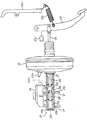
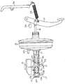
- FIG. 1 is a schematic view showing a first embodiment to which a vehicle brake device according to the present invention is applied. It is a figure which shows the state before stepping on a brake of the base hydraulic pressure braking force generator shown in FIG. It is a figure which shows the state in process of brake depression of the base hydraulic pressure braking force generator shown in FIG.
- FIG. 3 is a partial enlarged cross-sectional view of a first port shown in FIG. 2; It is a schematic diagram which shows the outline
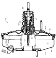
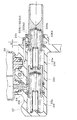
- FIG. It is a flowchart of a control program executed by the brake ECU shown in FIG. It is sectional drawing which shows the negative pressure type booster in 2nd Embodiment which applied the brake device for vehicles by this invention. It is a partial expanded sectional view of the negative pressure type booster shown in FIG. It is a correlation diagram of brake operation power and braking power by a 2nd embodiment to which a brake device for vehicles by the present invention is applied. It is sectional drawing of the master cylinder in 3rd Embodiment which applied the brake device for vehicles by this invention.
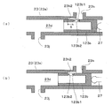
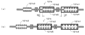
- FIG. 1 It is a partial expanded sectional view of a master cylinder in a 4th embodiment which applied a brake device for vehicles by the present invention, and (a) shows a state (the 1st position) before a brake depression of a foundation fluid pressure braking force generating device. It is a figure and (b) is a figure showing the state (especially 2nd position) in process of brake depression. It is a figure which shows an example of the spring for reaction force in 5th Embodiment which applied the brake device for vehicles by this invention, (a) shows the state of natural length, The figure which shows the state which (b) extended. It is.
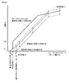
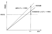
- FIG. 16 is a view showing a pedal effort-deceleration characteristic showing an action of a reaction force spring in a sixth embodiment to which a vehicle brake system according to the present invention is applied.
- FIG. 1 is a schematic view showing the configuration of the hybrid vehicle
- FIG. 2 is a schematic view showing the configuration of a basic hydraulic braking force generator of the vehicle brake system.
- a hybrid vehicle is a vehicle in which drive wheels such as left and right front wheels FL and FR are driven by a hybrid system, as shown in FIG.
- the hybrid system is a powertrain that uses two types of power sources of the engine 11 and the motor 12 in combination.
- it is a parallel hybrid system in which the wheels are directly driven by both the engine 11 and the motor 12.
- serial hybrid system other than this, in which the wheels are driven by the motor 12 and the engine 11 acts as a power supply source to the motor 12.
- a hybrid vehicle equipped with this parallel hybrid system includes an engine 11 and a motor 12.
- the driving force of the engine 11 is transmitted to the driving wheels (the left and right front wheels FL and FR in the first embodiment) via the power split mechanism 13 and the power transmission mechanism 14, and the driving force of the motor 12 Is transmitted to the drive wheels via the power transmission mechanism 14.
- the power split mechanism 13 appropriately splits the drive power of the engine 11 into a vehicle drive power and a generator drive power.
- the power transmission mechanism 14 appropriately integrates the driving forces of the engine 11 and the motor 12 according to the traveling conditions, and transmits the driving forces to the drive wheels.
- the power transmission mechanism 14 adjusts the transmitted driving power ratio of the engine 11 and the motor 12 between 0: 100 and 100: 0.
- the power transmission mechanism 14 has a speed change function.
- the motor 12 assists the output of the engine 11 to enhance the driving force, and generates electric power when the vehicle is braked to charge the battery 17.
- the generator 15 generates electric power by the output of the engine 11, and has a function of a starter at the time of engine start.
- the motor 12 and the generator 15 are electrically connected to the inverter 16 respectively.
- the inverter 16 is electrically connected to the battery 17 as a DC power supply, converts the AC voltage input from the motor 12 and the generator 15 into a DC voltage and supplies it to the battery 17, or conversely, from the battery 17 It converts DC voltage into AC voltage and outputs it to the motor 12 and the generator 15.
- the motor 12, the inverter 16, and the battery 17 constitute a regenerative braking device A.
- the regenerative braking device A is detected by a pedal stroke sensor 21a (or pressure sensor P).
- the regenerative braking force based on the brake operation state (described later) is selected from any of the wheels FL, FR, RL, RR (in the first embodiment, the left and right front wheels FL, FR driven by the motor 12 as the drive source) It is caused to
- the engine 11 is controlled by an engine ECU (electronic control unit) 18, and the engine ECU 18 outputs an opening degree command to the electronically controlled throttle in accordance with an engine output request value from a hybrid ECU (electronic control unit) 19 described later. Adjust the rotation speed of.
- the hybrid ECU 19 is connected such that the inverters 16 can communicate with each other.
- the hybrid ECU 19 derives the necessary engine output, electric motor torque and generator torque from the accelerator opening and the shift position (calculated from the shift position signal inputted from the shift position sensor not shown), and the derived engine output request value Are transmitted to the engine ECU 18 to control the driving force of the engine 11, and also control the motor 12 and the generator 15 through the inverter 16 in accordance with the derived electric motor torque request value and generator torque request value.
- the hybrid ECU 19 is connected to the battery 17 and monitors the charge state of the battery 17, charge current, and the like. Further, the hybrid ECU 19 is connected to an accelerator opening sensor (not shown) which is assembled to an accelerator pedal (not shown) and detects an accelerator opening of the vehicle, and receives an accelerator opening signal from the accelerator opening sensor. ing.
- the hybrid vehicle also includes a hydraulic brake device B that applies a hydraulic braking force directly to the wheels FL, FR, RL, RR to brake the vehicle.
- the hydraulic brake device B generates a base hydraulic pressure corresponding to a brake operation state by depression of the brake pedal 21 in the master cylinder 23, and generates the generated base hydraulic pressure with the master cylinder 23.
- the respective wheels FL , FR, RL, RR By directly applying the fluid pressure control valves 31, 41 to the wheel cylinders WC1, WC2, WC3, WC4 of the wheels FL, FR, RL, RR connected by the oil paths Lf, Lr, respectively, the respective wheels FL , FR, RL, RR generate a base fluid pressure braking force corresponding to the base fluid pressure, and drive and control the pumps 37, 47 independently of the base fluid pressure generated corresponding to the brake operation state
- the control hydraulic pressure formed by the control of the valves 31, 41 is applied to the wheel cylinders WC1, WC2, WC3, WC4 of the respective wheels FL, FR, RL, RR.
- the hydraulic brake device B is a negative pressure booster 22 which is a booster that boosts the suction operation force of the engine 11 by acting an intake negative pressure of the engine 11 on the diaphragm to assist the brake operation force generated by the stepping operation of the brake pedal 21.
- the brake fluid (oil) of the fluid pressure (hydraulic pressure) which is the basic fluid pressure corresponding to the brake operating force (that is, the operating state of the brake pedal 21) boosted by the negative pressure type booster 22
- a master cylinder 23 that supplies WC4, a reservoir tank 24 that stores brake fluid and supplies the master cylinder 23 with the brake fluid, and is provided between the master cylinder 23 and wheel cylinders WC1 to WC4 to control hydraulic pressure
- a brake actuator (control fluid pressure braking force generator) 25 to be formed is provided.
- the brake pedal 21, the negative pressure booster 22, the master cylinder 23, and the reservoir tank 24 constitute a basic hydraulic pressure braking force generator.
- the brake pedal 21 is connected to the negative pressure booster 22 via the operating rod 26, and the negative pressure booster 22 is connected to the master cylinder 23 via the push rod 27.
- the brake operating force applied to the motor 21 is input to the negative pressure booster 22 via the operating rod 26, boosted, and input to the master cylinder 23 via the push rod 27.
- the brake pedal 21 is provided with a pedal stroke sensor 21 a which detects a brake pedal stroke which is a brake operation state by depression of the brake pedal 21.
- the pedal stroke sensor 21 a is connected to the brake ECU 60, and a detection signal is transmitted to the brake ECU 60.
- the brake pedal 21 is provided with a reaction force spring 21b which is a pedal reaction force forming means for forming a pedal reaction force of the brake pedal 21 until the brake operation state becomes a predetermined state (described later).
- the reaction force spring 21b is connected at one end to the bracket 10a fixed to the vehicle body of the vehicle, and the brake release direction (the brake pedal 21 is not depressed before the brake pedal 21 is depressed). In the direction of returning to the original position).
- the biasing force of the reaction force spring 21b is desirably set in consideration of the inner diameter of the housing 23a of the master cylinder 23, the boosting ratio, and the like.
- the negative pressure booster 22 is generally well known, and the negative pressure inlet 22a is in communication with the intake manifold of the engine 11, and the negative pressure of the intake manifold is used as a boosting source.
- master cylinder 23 is a tandem-type master cylinder, and is housed with housing 23 a formed in a bottomed cylindrical shape and the inside of housing 23 a in a liquid-tight and slidable manner.
- First and second pistons 23b and 23c, a first spring 23e disposed in a first fluid pressure chamber 23d formed between the first piston 23b and the second piston 23c, and a second piston 23c It comprises: a second spring 23g disposed in a second hydraulic pressure chamber 23f formed between the housing 23a and the closed end of the housing 23a.
- the second piston 23c is urged toward the opening end (the first piston 23b side) by the second spring 23g, and the first piston 23b is urged toward the opening end by the first spring 23e.
- One end (open end side end) of 23 b is pressed to abut on the tip of the push rod 27.
- the housing 23a of the master cylinder 23 has a first port 23h for communicating the first fluid pressure chamber 23d with the reservoir tank 24, and a second port 23i for communicating the second fluid pressure chamber 23f with the reservoir tank 24. And are provided.
- the first port 23 h is a first piston 23 b in a first position (return position: the state shown in FIG. 2) in which the driver's foot is away from the brake pedal 21, that is, the brake pedal 21 is not depressed.
- the second port 23i has an open end that closes the second port 23i of the second piston 23c at the first position (return position: the state shown in FIG. 2). (Ie, the position immediately before the closed end of the second piston 23c starts closing the opening of the second port 23i).
- the predetermined state is a brake operation state in which the generation restriction of the base hydraulic pressure braking force is released and the base hydraulic pressure braking force starts to increase the pressure corresponding to the brake operation state. Further, it is desirable that the predetermined distance S be set so that the regenerative braking device A generates the maximum regenerative braking force when the brake operation state is the predetermined state. Thus, when the brake operation state becomes the predetermined state, the master cylinder 23 releases the restriction on the generation of the base hydraulic pressure braking force and the regenerative brake device A generates the maximum regenerative braking force.
- an orifice 23 h 1 is provided in the first port 23 h.
- the orifice 23h1 is configured to restrict the flow of brake fluid from the master cylinder 23 to the reservoir tank 24 when the brake pedal 21 is suddenly depressed, and not to restrict the flow of brake fluid when the brake pedal 21 is not depressed.
- the inner diameter of the orifice 23h1 is set smaller than the inner diameter of the third port 23j (the flow passage cross-sectional area is set small).
- the housing 23a of the master cylinder 23 constitutes a third port 23j for communicating the first hydraulic pressure chamber 23d with the oil passage Lr constituting the rear wheel system, and the second hydraulic pressure chamber 23f and the front wheel system.
- a fourth port 23k for communicating with the oil path Lf is provided.
- the oil passage Lr communicates the first fluid pressure chamber 23d with the wheel cylinders WC3 and WC4 of the left and right rear wheels RL and RR
- the oil passage Lf is a second fluid pressure chamber.
- 23f is communicated with the wheel cylinders WC1 and WC2 of the left and right front wheels FL and FR, respectively.
- the respective braking means BK1, BK2, BK3, BK4 provided corresponding to WC4 are operated to apply a hydraulic braking force (base hydraulic braking force, braking hydraulic braking force) to each wheel FL, FR, RL, RR .
- the brake means BK1, BK2, BK3, BK4 include disc brakes, drum brakes and the like, and friction members such as brake pads and brake shoes regulate the rotation of the disc rotor and brake drums integrated with the wheels. ing.
- the brake fluid in the first fluid pressure chamber 23d flows out to the reservoir tank 24 through the first port 23h without the back pressure (the brake fluid pressure in the first port 23h) rising. Therefore, no base fluid pressure is generated in the first fluid pressure chamber 23d.
- the first spring 23e is pushed and compressed by the movement of the first piston 23b, since the base hydraulic pressure is not generated in the first hydraulic pressure chamber 23d, the second piston 23c is directed in the left direction in FIG. Direction) and the second port 23i does not start closing by the closed end of the second piston 23c, so that the base hydraulic pressure does not occur in the second hydraulic pressure chamber 23f.
- the first piston 23b moves by a value obtained by adding the diameter of the first port 23h to the predetermined distance S in the left direction in the drawing, the first port 23h is closed by the closed end of the first piston 23b, and the inside of the first hydraulic pressure chamber 23d Since the brake fluid can not flow out to the reservoir tank 24 through the first port 23h and the first fluid pressure chamber 23d is sealed, formation of a base fluid pressure is started in the first fluid pressure chamber 23d.
- the second piston 23c is pushed in the left direction in the drawing by the base hydraulic pressure generated in the first hydraulic pressure chamber 23d and instantaneously closes the second port 23i by the closed end.
- the brake fluid can not flow out to the reservoir tank 24 through the second port 23i and the inside of the second fluid pressure chamber 23f is sealed, so the formation of the base fluid pressure is also started in the second fluid pressure chamber 23f. .
- the brake pedal 21 when the brake pedal 21 is further stepped on from the state where formation of the base fluid pressure is started in the first and second fluid pressure chambers 23d and 23f and the foot pedal is in the state shown in FIG. From the start to the depression state shown in FIG. 3 (after the base fluid pressure formation start state), the base fluid pressure corresponding to the brake operation state is generated in the first and second fluid pressure chambers 23d and 23f. ing.
- the base fluid pressures generated in the first and second fluid pressure chambers 23d and 23f are the same.
- the biasing forces of the first and second springs 23e and 23g and the oil paths Lr and Lf of the first and second pistons 23b and 23c respectively.
- the pressure is set to return to the original position (first position).
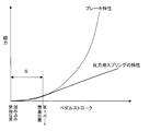
- the base hydraulic pressure braking force by the base hydraulic pressure formed by the above-described master cylinder 23 is as shown by a broken line in FIG. That is, when the brake pedal stroke is positioned between the depression start position and the position closing the first port 23h, the base hydraulic pressure generated in the first and second hydraulic chambers 23d and 23f of the master cylinder 23 is 0. Therefore, the generation of the base fluid pressure braking force is also limited to zero.
- the brake pedal stroke is located at a position beyond the position closing the first port 23h, the above-described base hydraulic pressure generation restriction is released and occurs in the first and second hydraulic pressure chambers 23d and 23f. Since the base fluid pressure corresponds to the brake pedal stroke, the base fluid pressure braking force also corresponds to the brake pedal stroke.
- the state where the brake pedal stroke is positioned at the position closing the first port 23h is a predetermined state, and the basic hydraulic pressure braking force is a brake operation state where pressure boosting corresponding to the brake pedal stroke is started. Therefore, as shown by the broken line in FIG. 6, by applying the base hydraulic pressure directly to the wheel cylinders WC1, WC2, WC3, WC4, the foundation corresponding to the basic hydraulic pressure to the respective wheels FR, FL, RR, RL A hydraulic braking force can be generated.
- the second piston 23c is pushed in the left direction in the drawing by the base hydraulic pressure generated in the first hydraulic pressure chamber 23d and instantaneously closes the second port 23i by the closed end.
- the brake fluid can not flow out to the reservoir tank 24 through the second port 23i and the inside of the second fluid pressure chamber 23f is sealed, so the formation of the base fluid pressure is also started in the second fluid pressure chamber 23f.
- the basic hydraulic pressure braking force can be positively generated when the brake pedal stroke is positioned between the depression start position and the position closing the first port 23h. it can.
- the regenerative brake device A uses the regenerative braking force to compensate for the insufficient amount of the basic hydraulic braking force to the vehicle braking force by cooperative operation with the hydraulic brake device B for achieving the vehicle braking force corresponding to the brake operation state. compensate. Therefore, in the low pedaling force area from the depression start position to the position where the first port 23h is closed, when the brake pedal 21 is suddenly depressed, the basic hydraulic pressure braking force is given priority over high regeneration efficiency and high fuel efficiency. It can be granted.
- the first piston 23b moves leftward in the drawing by a value obtained by adding the diameter of the first port 23h to the predetermined distance S by the predetermined distance S, the first port 23h is closed by the closed end of the first piston 23b, and the first hydraulic pressure chamber 23d Since the brake fluid in the inside can not completely flow out to the reservoir tank 24 through the first port 23h and the inside of the first fluid pressure chamber 23d is sealed, an increase in the base fluid pressure generated in the first fluid pressure chamber 23d The mass will be larger.
- the base hydraulic pressure braking force by the base hydraulic pressure formed by the above-described master cylinder 23 is as shown by a solid line in FIG. That is, when the brake pedal stroke is positioned between the depression start position and the position closing the first port 23h, the generation of the base fluid pressure generated in the first and second fluid pressure chambers 23d and 23f is not restricted. , Occurs according to the pedal stroke. Accordingly, the base fluid pressure braking force also corresponds to the brake pedal stroke. When the brake pedal stroke is positioned beyond the position closing the first port 23h, the base hydraulic pressure corresponds to the brake pedal stroke, so the base hydraulic pressure braking force also corresponds to the brake pedal stroke. It becomes.
- the inclination of the base hydraulic pressure braking force at the time of rapid depression and the inclination of the basic hydraulic pressure braking force at the time of non-urgent depression are determined by the characteristics of the master cylinder 23 and the negative pressure booster 22 and have the same characteristics.
- the rise time of the basic fluid pressure braking force at the time of rapid depression is earlier than at the time of non-rapid depression.
- the brake actuator 25 is generally well known, and includes fluid pressure control valves 31, 41, pressure increase control valves 32, 33, 42, 43 constituting an ABS control valve, and pressure decrease control valves 35, 36. , 45, 46, pressure control reservoirs 34, 44, pumps 37, 47, motor M, etc. are packaged in one case.
- the oil path Lf is provided with a hydraulic pressure control valve 31 configured of a differential pressure control valve.
- the fluid pressure control valve 31 is controlled by the brake ECU 60 to switch between the communication state and the differential pressure state.
- the fluid pressure control valve 31 is normally in communication, but the pressure in the oil passage Lf2 on the wheel cylinder WC1 and WC2 side is higher by a predetermined differential pressure than the oil passage Lf1 on the master cylinder 23 side by differential pressure. Can be held in The differential pressure is adjusted by the brake ECU 60 according to the control current.
- the oil path Lf2 is branched into two, one of which is provided with a pressure increase control valve 32 for controlling the pressure increase of the brake fluid pressure to the wheel cylinder WC1 in the pressure increase mode of the ABS control, and the other has an ABS
- a pressure increase control valve 33 is provided to control the pressure increase of the brake fluid pressure to the wheel cylinder WC2 in the pressure increase mode of control.
- the pressure increase control valves 32 and 33 are configured as two-position valves that can control the communication / disconnection state by the brake ECU 60.
- the pressure increase control valves 32, 33 are controlled to be in a continuous communication state. Further, safety valves 32a and 33a are provided in parallel to pressure increase control valves 32 and 33, respectively, and when the brake pedal 21 is released at the time of ABS control, the brake fluid from the wheel cylinders WC1 and WC2 side is accompanied accordingly. Is returned to the reservoir tank 24.
- the oil passage Lf2 between the pressure increase control valves 32, 33 and the wheel cylinders WC1, WC2 is in communication with the pressure control reservoir 34 via the oil passage Lf3.
- pressure reduction control valves 35, 36 capable of controlling the communication / disconnection state by the brake ECU 60 are respectively disposed. These pressure reduction control valves 35 and 36 are always in the shutoff state in the normal braking state (at the time of ABS non-operation), and appropriately release the brake fluid to the pressure control reservoir 34 through the oil passage Lf3 as the communication state, , WC2 to control the brake fluid pressure to prevent the wheels from becoming locked.
- a pump 37 is disposed together with a safety valve 37a in an oil path Lf4 connecting the oil path Lf2 and the pressure control reservoir 34 between the fluid pressure control valve 31 and the pressure increase control valves 32,33.
- An oil passage Lf5 is provided to connect the pressure control reservoir 34 to the master cylinder 23 via the oil passage Lf1.
- the pump 37 is driven by the motor M according to a command from the brake ECU 60.
- the pump 37 sucks in the brake fluid in the wheel cylinders WC1 and WC2 or the brake fluid stored in the pressure regulation reservoir 34 in the pressure reduction mode of the ABS control and is in communication with the master via the fluid pressure control valve 31 in communication state. It is returned to the cylinder 23.
- the pump 37 is switched to the hydraulic pressure control valve 31 switched to the differential pressure state.
- the brake fluid in the master cylinder 23 is sucked through the oil paths Lf1 and Lf5 and the pressure control reservoir 34, and the oil paths Lf4 and Lf2 and the pressure increase control valves 32 and 33 in communication.
- the control hydraulic pressure is applied by discharging the wheel cylinders WC1 and WC2.
- An accumulator 38 is disposed on the upstream side of the pump 37 of the oil path Lf4 in order to reduce the pulsation of the brake fluid discharged by the pump 37.
- a pressure sensor P for detecting a master cylinder pressure which is a brake hydraulic pressure in the master cylinder 23 is provided in the oil path Lf1, and this detection signal is transmitted to the brake ECU 60.
- the pressure sensor P may be provided on the oil path Lr1.
- the rear wheel system of the brake actuator 25 has a configuration similar to that of the front wheel system described above, and the oil passage Lr constituting the rear wheel system is comprised of oil passages Lr1 to Lr5, as with the oil passage Lf.
- the oil path Lr is provided with a fluid pressure control valve 41 similar to the fluid pressure control valve 31 and a pressure control reservoir 44 similar to the pressure control reservoir 34.
- the branched oil paths Lr2 and Lr2 communicated with the wheel cylinders WC3 and WC4 are provided with pressure increase control valves 42 and 43 similar to the pressure increase control valves 32 and 33, and the oil path Lr3 is provided with pressure reduction control valves 35 and 36 Similar pressure reduction control valves 45, 46 are provided.
- the oil path Lr4 is provided with a pump 37, a pump 47 similar to the safety valve 37a and the accumulator 38, a safety valve 47a and an accumulator 48.
- the pressure increase control valves 42 and 43 are provided in parallel with safety valves 42 a and 43 a similar to the safety valves 32 a and 33 a, respectively.
- control hydraulic pressure formed by driving the pumps 37 and 47 and controlling the hydraulic control valves 31 and 41 is applied to the wheel cylinders WC1, WC2, WC3 and WC4 of the respective wheels FL, FR, RL and RR.
- the control fluid pressure braking force can be generated on each of the wheels FL, FR, RL, RR.
- the vehicle brake system mainly includes wheel speed sensors Sfl, Sfr, Srl, Srr, and pressure which detect the wheel speeds of the pedal stroke sensor 21a and the wheels FL, FR, RL, RR, respectively.
- a sensor P, control valves 31, 32, 33, 33, 35, 36, 41, 42, 43, 45, and 46, and a brake ECU (electronic control unit) 60 connected to a motor M are provided.
- the brake ECU 60 switches and controls the states of the control valves 31, 32, 33, 35, 36, 41, 42, 43, 45, and 46 of the hydraulic brake device B based on the detection by these sensors and the state of the shift switch.
- the control hydraulic pressure applied to the wheel cylinders WC1 to WC4 that is, the control hydraulic pressure braking force applied to the wheels FL, FR, RL, and RR is controlled.
- the brake ECU 60 is communicably connected to each other to the hybrid ECU 19 and performs coordinated control of the regenerative brake and the hydraulic brake performed by the motor 12 so that the total braking force of the vehicle becomes equivalent to that of the hydraulic brake only vehicle. .
- the brake ECU 60 in response to a driver's braking request, ie, a braking operation state, the brake ECU 60 sends a regeneration request value, which is a share of the regenerative braking device among the total braking force, to the hybrid ECU 19 as a target value of the regenerative braking device, ie, target regeneration. Output as a braking force.
- the hybrid ECU 19 derives an actual regeneration execution value to be actually acted as a regeneration brake in consideration of the vehicle speed, the battery charge state, etc. based on the input regeneration request value (target regenerative braking force), and regeneration corresponding to the actual regeneration execution value.
- the motor 12 is controlled via the inverter 16 to generate a braking force, and the derived actual regeneration execution value is output to the brake ECU 60.
- the brake ECU 60 applies the basic hydraulic pressure braking force applied to the wheels FL, FR, RL, RR by the brake means BK1, BK2, BK3, BK4.
- the brake ECU 60 maps the target regenerative braking force to be applied to the wheels FL, FR, RL, RR according to the brake operation state which is the stroke of the brake pedal (or the master cylinder pressure), maps it into a table or arithmetic expression and stores it. It is stored in advance.
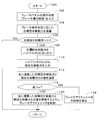
- the brake ECU 60 stores a coordinated control program (a vehicle brake control program) shown in FIG.
- the brake ECU 60 executes a program corresponding to the above-described flowchart at predetermined short intervals.
- the brake ECU 60 inputs a pedal stroke which is the operating state of the brake pedal 21 from the pedal stroke sensor 21a (step 102), and calculates a target regenerative braking force according to the input pedal stroke (step 104).
- the brake ECU 60 uses a map, a table or an arithmetic expression indicating the relationship between the pedal stroke stored in advance, that is, the brake operation state and the target regenerative braking force to be applied to the wheels FL, FR, RL, RR.
- the target regenerative braking force calculated in step 104 is output to the hybrid ECU 19 and control is not performed on the brake actuator 25 (steps 106 and 108). Therefore, when the brake pedal 21 is depressed, the hydraulic brake device B applies only the basic hydraulic braking force (static pressure brake) to the wheels FL, FR, RL, RR as in the case described above.
- the hybrid ECU 19 inputs a regeneration request value indicating the target regenerative braking force, and based on the value, the motor 12 is transmitted via the inverter 16 so as to generate the regenerative braking force in consideration of the vehicle speed and the battery charge state. While performing control, the actual regeneration execution value is output to the brake ECU 60.
- FIG. 6 shows the correlation between the brake operating force at the time of regenerative coordinated control and the braking force indicating the sum of the base fluid pressure braking force and the regenerative braking force.
- the master cylinder 23 when the brake pedal 21 is not depressed suddenly, the base fluid is changed from the depression start state which is the state at the depression start time to the predetermined state.
- the generation is limited so that the pressure braking force becomes equal to or less than a predetermined value.
- the basic hydraulic pressure braking force is forcibly limited to a predetermined value or less between the depression start state and the predetermined state. Only the regenerative braking force is applied according to the brake operation state.
- the brake operation state when the brake operation state is in the predetermined state, the restriction on the generation of the base hydraulic pressure braking force is released, and the regenerative braking device A generates the maximum regenerative braking force, so only the maximum regenerative braking force is applied. Ru. Furthermore, when the brake operation state is depressed from the predetermined state, the release of the restriction on the generation of the base hydraulic pressure braking force is maintained, and the hydraulic brake device B and the regenerative brake device A operate in coordination with each other. A vehicle braking force corresponding to the brake operation state is applied based on the hydraulic pressure braking force and the regenerative braking force (basically, the maximum regenerative braking force).
- the brake ECU 60 detects the fluctuation of the regenerative braking force actually generated by the regenerative brake device A (steps 110 to 114). Specifically, the brake ECU 60 performs actual regeneration execution indicating the actual regenerative braking force actually applied to the wheels FL, FR, RL, and RR by the regenerative braking device A with respect to the target regenerative braking force calculated in step 104. A value is input (step 110), and the difference between the target regenerative braking force calculated in step 104 and the actual regenerative braking force input in step 110 is calculated (step 112), and the calculated difference is a predetermined value. If it is larger than a, it is detected that the regenerative braking force has fluctuated (step 114).
- the brake ECU 60 When the brake ECU 60 detects a change in regenerative braking force, it determines YES in step 114 and drives the pumps 37, 47 of the hydraulic brake device B and controls the hydraulic control valves 31, 41. By forming a control hydraulic pressure and applying a control hydraulic braking force based on the control hydraulic pressure to the wheels FL, FR, RL, RR, the shortage of the braking force due to the fluctuation of the regenerative braking force detected as described above is compensated. (Step 116). Specifically, the brake ECU 60 determines the difference between the target power calculated at step 104 and the actual regenerative braking force input at step 110, that is, the hydraulic pressure corresponding to the difference calculated at step 112.
- Control hydraulic pressure to be The brake ECU 60 starts the motor M to drive the pumps 37 and 47 so that the hydraulic pressure of the brake fluid supplied from the pumps 37 and 47 to the wheel cylinders WC1, WC2, WC3 and WC4 becomes the control hydraulic pressure.
- a current is applied to the linear solenoids of the pressure control valves 31 and 41.
- the linear solenoid 33 be feedback-controlled so that the fluid pressure of the wheel cylinders WC1, WC2, WC3 and WC4 detected by the fluid pressure sensor 40 becomes the control fluid pressure.
- the brake ECU 60 does not detect the fluctuation of the regenerative braking force, it is determined as NO in step 114, and the control of the brake actuator 25 is stopped (step 118).
- the flow of brake fluid from the master cylinder 23 to the reservoir tank 24 is the first port 23 h (port). It is not limited by the orifice 23h1 provided in. Therefore, the generation of the base fluid pressure braking force is limited until the closed end of the first piston 23b becomes from the first position to the second position. Thereby, when the driver depresses the brake pedal 21, when the closed end of the first piston 23b is located between the first position and the second position, the base hydraulic pressure braking force is forcibly limited to a predetermined value or less. Ru.
- the regenerative brake device A performs regenerative braking force on the insufficient portion of the basic fluid pressure braking force with respect to the vehicle braking force by cooperative operation with the hydraulic brake device B for achieving the vehicle braking force corresponding to the brake operation state. Make up for.
- the closed end of the first piston 23b is located between the first position and the second position.
- the vehicle braking force corresponding to the operation state of the brake pedal 21 is applied to the vehicle only by the regenerative braking force generated by the regenerative braking device A, and the closed end of the first piston 23b is positioned at the second position.
- the vehicle braking force corresponding to the operation state of the brake pedal 21 is applied to the vehicle by the maximum regenerative braking force that can be generated by the regenerative braking device A, and the closed end of the first piston 23b is positioned beyond the second position
- the closed end of the first piston 23b actively utilizes the regenerative braking force, and achieves high regenerative efficiency, that is, high fuel efficiency. it can.
- the base hydraulic pressure is formed in the first hydraulic pressure chamber 23 d (hydraulic pressure chamber) of the master cylinder 23, so that the first piston 23 d is not closed by the first port 23 h.
- the base fluid pressure braking force can be generated during the period from when the closed end of the first piston 23d becomes from the first position to the second position.
- the regenerative brake device A performs regenerative braking force on the insufficient portion of the basic fluid pressure braking force with respect to the vehicle braking force by cooperative operation with the hydraulic brake device B for achieving the vehicle braking force corresponding to the brake operation state. Make up for. Therefore, when the closed end of the first piston 23d is in the low depression force area from the first position to the second position, when the brake pedal 21 is suddenly depressed, the basic hydraulic pressure braking force is applied earlier than high regenerative efficiency and high fuel efficiency. Can be
- high regenerative efficiency is achieved by actively utilizing regenerative braking force when not stepping in the low pedaling force region from the start of depression of the brake pedal 21 to the predetermined state.
- the brake pedal 21 includes a reaction force spring 21b that forms a pedal reaction force of the brake pedal 21 from the first position to the second position when the closed end of the first piston 23b becomes the second position, and the reaction force spring 21b is connected to a bracket 10a fixed at one end to the vehicle body of the vehicle, and biases the brake pedal 21 in a depression release direction opposite to the depression direction.
- the biasing force of the reaction force spring 21b gives the driver a good pedal feeling. It can be granted.
- the brake operation state may be detected by the master cylinder stroke sensor 23z that detects the stroke of the master cylinder 23. Further, an orifice similar to the orifice 23h may be provided in the second port 23i.
- the negative pressure type booster 22 of the hydraulic pressure brake device B described above was not equipped with the brake assist device
- the negative pressure type booster 122 of the hydraulic pressure brake device B according to the second embodiment is a brake assist device Is equipped.
- the brake assist device is a device that assists a small stepping force to form and apply a large braking force.
- a negative pressure type booster 122 includes a front shell 81a, a rear shell 81b, and a movable wall 82, and includes a housing 81 whose inside is divided by a movable wall 82 into a constant pressure chamber R1 and a variable pressure chamber R2.
- the movable wall 82 in the housing 81 is made of a metal plate 82a and a rubber diaphragm 82b, and is disposed movably in the front-rear direction with respect to the housing 81.
- the constant pressure chamber R1 is in communication with an engine intake manifold (not shown) which is a negative pressure source, and is always kept at negative pressure during engine operation.
- the variable pressure chamber R2 communicates with and shut off from the constant pressure chamber R1 through the passage 83 and the valve mechanism 84, and also communicates and shuts off from the atmosphere through the valve mechanism 84.
- the plunger As shown in FIG. 9, in the negative pressure type booster 122, when the relative movement amount between the operating rod 26 and the power piston 85 becomes larger than the predetermined value A at the time of rapid depression when the driver suddenly depresses the brake pedal 21, the plunger The sloped surface portion 86 b of 86 abuts on the tapered portion 87 a of the holding member 87 and radially expands the diameter of the holding member 87 urged in the direction of diameter reduction by the ring-shaped elastic body 88.
- valve seat member 89 moves rearward, the second negative pressure valve seat 92 of the valve seat member 89 abuts on the valve 93a that constitutes the movable portion 93 of the valve mechanism 84, and communication between the constant pressure chamber R1 and the variable pressure chamber R2 is achieved. Cut off.
- the plunger 86 is moving forward integrally with the operating rod 26, and the valve seat member 89 pushes back the movable portion 93 of the valve mechanism 84, so the atmosphere valve seat 86a of the plunger 86 and the valve
- the valve 93 b constituting the movable portion 93 of the mechanism 84 is quickly separated from the pressure chamber R 2 to communicate with the atmosphere.
- the communication shut-off between the constant pressure chamber R1 and the variable pressure chamber R2 and the communication between the variable pressure chamber R2 and the atmosphere are performed more rapidly.
- the distance between the contact surface 85d and the first negative pressure valve seat 95 and the distance between the contact surface 85d of the power piston 85 against the reaction force member 94 and the atmospheric valve seat 86a are enlarged, and the output in the jumping state Can be made larger than in the normal state.
- the emergency braking characteristic of the negative pressure type booster of this embodiment is achieved by changing the jumping characteristic and applying a propulsive force to the output member greater than that during normal braking.
- the gap B between the contact member 96 and the reaction member 94 may be increased in FIG.
- the gap B is enlarged by the distance between the contact surface 85d of the power piston 85 to the reaction member 94 and the first negative pressure valve seat 95, and the contact surface 85d of the power piston 85 to the reaction member 94 and the atmosphere valve seat It is the same as enlarging the distance to 86a.
- the gap B is enlarged by moving the negative pressure valve seat 38 and the atmosphere valve seat 86 a backward, the output until the contact member 96 receives the reaction force from the reaction force member 94 is increased, and the output for the input
- the output in the so-called jumping state where the ratio of becomes infinite is larger than that in the normal state.
- the normal brake characteristic and the emergency brake characteristic are shown in FIG. In FIG. 10, the jumping in the normal brake can only obtain an output of the magnitude of F1, but the jumping in the emergency braking increases to F2, and a small pedal effort produces a sufficiently large brake fluid pressure. It can be done.
- the brake assist is started between the depression start position of the first operating rod 26a and the contact position.
- the brake assist device is configured such that the brake assist is started between the start of depression of the brake pedal and movement by a predetermined distance in the pressure increasing direction when the brake pedal is suddenly depressed. It is done.
- the flow of brake fluid from the master cylinder 23 to the reservoir tank 24 is the first port 23 h (port). It is not limited by the orifice 23h1 provided in. Therefore, the same operation and effect as the first embodiment described above can be obtained.
- the base fluid pressure braking force by the base fluid pressure formed by the fluid pressure brake device B is as shown by a thick solid line in FIG. That is, when the brake pedal stroke is positioned between the depression start position and the brake assist start position (hereinafter referred to as the BA start position) at which the brake assist is started, the basics at the time of rapid depression according to the first embodiment As with the hydraulic braking force, the generation of the base hydraulic pressure is not limited and occurs in response to the pedal stroke. Furthermore, when the brake pedal stroke is located at a position beyond the BA start position, the base hydraulic pressure braking force by the brake assist device is applied corresponding to the brake pedal stroke.
- high regenerative efficiency is achieved by actively utilizing regenerative braking force when not stepping in the low pedaling force region from the start of depression of the brake pedal 21 to the predetermined state.
- the brake assist device is configured by so-called mechanical brake assist, but an atmospheric pressure valve configured by a solenoid valve may be separately provided to control the opening and closing of this valve.
- it may be configured by a brake actuator 15 capable of generating a control hydraulic pressure.
- the brake fluid pressure device B preferably includes an accumulator capable of accumulating high pressure brake fluid.
- a first piston side port 223b1 and a second piston side port 223b2 are formed in the first piston 223b.
- the first piston 223 b is formed in a bottomed cylindrical shape (cup shape).
- the first piston 223 b is such that the opening side is open to the first fluid pressure chamber 23 d (opens toward the second piston 23 c), and the outer wall surface of the bottom is in contact with the push rod 27.
- the first piston side port 223b1 and the second piston side port 223b2 are arranged such that the first port 23h (master cylinder side port) formed in the master cylinder 23 is faced before the brake pedal 21 starts to be depressed (see FIG. 11). It is set up.
- the reservoir tank 24 is in communication with the first fluid pressure chamber 23 d through the first port 23 h and the first piston side port 223 b 1 and the second piston side port 223 b 2.
- the brake pedal 21 is in the depression start state, and the first piston 223 b is in the first position in the depression start state.
- the first piston port 223b1 When the first piston 223b is in the first position, the first piston port 223b1 is separated from the closed end 23h2 of the first port 23h by a predetermined distance S in the pressure reducing direction of the first piston 223b (rightward in FIG. 11). It is located in the
- an orifice 223b3 is provided in the first piston side port 223b1.
- the orifice 223b3 is set to restrict the flow of brake fluid from the master cylinder 23 to the reservoir tank 24 when the brake pedal 21 is suddenly depressed, and not to restrict the flow of brake fluid when the brake pedal 21 is not depressed. ing.
- the inner diameter of the orifice 223b3 is set smaller than the inner diameter of the third port.
- a port (not shown) communicating with a hydraulic pressure path constituting a rear wheel system similar to the third port 23j is formed, and in the second fluid pressure chamber 23f, a fourth port 23k and A port (not shown) in communication with a hydraulic pressure path constituting a similar front wheel system is formed.
- the second piston side port 223b2 is provided apart from the first piston side port 223b1 by a predetermined distance S in the pressure increasing direction (left direction in FIG. 11) of the first piston 223b. Further, when the first piston 223b is in the first position, the second piston side port 223b2 coincides with the closed end 23h2 of the first port 23h, and is in a state just before closing. Further, the inner diameter of the second piston side port 223b2 is set larger than the inner diameter of the first piston side port 223b1, and even when the brake pedal 21 is suddenly depressed, the back pressure hardly increases.
- the flow of the brake fluid from the master cylinder 23 to the reservoir tank 24 is not restricted by the orifice 223 b 3 of the first piston side port 223 b 1. Therefore, the brake fluid in the first fluid pressure chamber 23 d flows out to the reservoir tank 24 through the first piston side port 223 b 1, the second piston side port 223 b 2 and the first port 23 h without the back pressure rising.
- the base fluid pressure is not generated in the first fluid pressure chamber 23d.
- a position away from the first position by a predetermined distance S in the pressure increasing direction is a second position.
- the first piston 223b moves leftward in the drawing by a value obtained by adding the inner diameter of the first piston side port 223b1 to a predetermined distance S, ie, when the first piston 223b exceeds the predetermined distance S, the first piston side port 223b1 Is completely blocked by the closed end 23h2 of the first port 23h, and the brake fluid in the first fluid pressure chamber 23d can not flow out to the reservoir tank 24 through the first piston side port 223b1 and the first port 23h. Since the inside of the pressure chamber 23d is sealed, formation of a base hydraulic pressure is started in the first liquid pressure chamber 23d.
- the basic hydraulic pressure braking force by the basic hydraulic pressure formed by the master cylinder 23 according to the present embodiment is as shown by the broken line in FIG. 6 as in the first embodiment described above. That is, when the brake pedal stroke is positioned between the depression start position and the position closing the first piston side port 223b1, the basic hydraulic pressure generated in the first and second hydraulic pressure chambers 23d and 23f of the master cylinder 23 Is limited to zero, the generation of the base hydraulic braking force is also limited to zero. Then, when the brake pedal stroke is located at a position beyond the position where the first piston side port 223b1 is closed, the generation restriction of the base hydraulic pressure described above is released, and the first and second hydraulic pressure chambers 23d and 23f are opened.
- the base fluid pressure braking force also corresponds to the brake pedal stroke.
- the state where the brake pedal stroke is located at the position where the first piston side port 223b1 is closed is the predetermined state, and the basic hydraulic pressure braking force is the brake operation state where pressure boosting corresponding to the brake pedal stroke is started. Therefore, as shown by the broken line in FIG. 6, by applying the base hydraulic pressure directly to the wheel cylinders WC1, WC2, WC3, WC4, the foundation corresponding to the basic hydraulic pressure to the respective wheels FR, FL, RR, RL A hydraulic braking force can be generated.
- the regenerative braking force is applied in the same manner as the first embodiment described above.
- the second position (predetermined distance S) is set based on the maximum regenerative braking force that can be generated by the regenerative braking device A.
- the vehicle braking force corresponding to the operation state of the brake pedal is applied to the vehicle only by the regenerative braking force generated by the regenerative braking device A.
- the vehicle braking force corresponding to the operation state of the brake pedal 21 is applied to the vehicle by the maximum regenerative braking force that can be generated by the regenerative braking device A.
- the back pressure is increased, so that the brake fluid in the first hydraulic pressure chamber 23d is suppressed from flowing out to the reservoir tank 24 through the first piston side port 223b1 and the first port 23h. Therefore, a base fluid pressure is generated in the first fluid pressure chamber 23d.
- the basic hydraulic pressure braking force is positively generated when the brake pedal stroke is positioned between the depression start position and the position closing the first piston side port 223b1. be able to.
- the regenerative brake device A uses the regenerative braking force to compensate for the insufficient amount of the basic hydraulic braking force to the vehicle braking force by cooperative operation with the hydraulic brake device B for achieving the vehicle braking force corresponding to the brake operation state. compensate. Therefore, in the low pedaling force region from the depression start position of the brake pedal stroke to the position where the first piston side port 223b1 is closed, basic hydraulic braking force is prioritized over high regeneration efficiency and high fuel efficiency when the brake pedal 21 is suddenly depressed.
- the first piston side port 223b1 is closed by the closed end 23h2 of the first port 23h.
- the base hydraulic pressure braking force by the base hydraulic pressure formed by the master cylinder 23 according to the present embodiment is as shown by the solid line in FIG. 6 as in the first embodiment described above. That is, when the brake pedal stroke is positioned between the depression start position and the position closing the first piston side port 223b1, generation of the base hydraulic pressure generated in the first and second hydraulic pressure chambers 23d and 23f is limited. It does not occur (the occurrence restriction is released) and occurs according to the pedal stroke. Accordingly, the base fluid pressure braking force also corresponds to the brake pedal stroke. When the brake pedal stroke is positioned beyond the position where the first piston side port 223b1 is closed, the base hydraulic pressure corresponds to the brake pedal stroke, so the base hydraulic pressure braking force also corresponds to the brake pedal stroke. It will be done.
- the flow of the brake fluid from the master cylinder 23 to the reservoir tank 24 is not restricted by the orifice 223b3 provided in the first piston side port 223b1. Therefore, the generation of the basic fluid pressure braking force is restricted during the period from the first position to the second position (from the start of depression of the brake pedal 21 to the movement by the predetermined distance S in the pressure increasing direction) Be done. Therefore, as in the first embodiment described above, regenerative braking force is positively utilized in the low pedaling force region from the first position to the second position of the first piston 223b, and high regenerative efficiency, That is, high fuel consumption can be achieved.
- high regenerative efficiency is achieved by actively utilizing regenerative braking force when not stepping in the low pedaling force region from the start of depression of the brake pedal 21 to the predetermined state.
- the brake pedal 21 includes a reaction force spring 21b that forms a pedal reaction force of the brake pedal 21 from the start of depression of the brake pedal 21 to movement by a predetermined distance S in the pressure increasing direction, and the reaction force
- the spring 21b is connected at one end to a bracket 10a fixed to the vehicle body of the vehicle, and is adapted to bias the brake pedal 21 in a depression release direction opposite to the depression direction. .
- the second piston of the second hydraulic pressure chamber 23f is configured in the same manner as the first piston 223b, and the second piston has the same first and second piston sides as the first and second piston side ports 223b1 and 223b2.
- a port may be formed, and the first piston side port may be provided with an orifice similar to the orifice 223b3.
- a piston side port 123b1 (second port) is formed in the first piston 123b.
- the first piston 123 b is formed in a bottomed cylindrical shape (cup shape).
- the first piston 123 b is such that the opening side opens to the first fluid pressure chamber 23 d (opens toward the second piston 23 c), and the outer wall surface of the bottom abuts on the push rod 27.
- the piston side port 123b1 is disposed such that the brake pedal 21 faces the first port 23h formed in the master cylinder 23 in the depression start state (see FIG. 12A).
- the reservoir tank 24 is in communication with the first fluid pressure chamber 23 d via the first port 23 h and the piston side port 123 b 1.
- the brake pedal 21 is in the depression start state
- the first piston 123b is in the first position in the depression start state.
- the piston side port 123b1 is a position separated from the closed end 23h2 of the first port 23h by a predetermined distance S in the pressure reducing direction of the first piston 123b (rightward in FIG. 12).
- an orifice 123b2 is provided in the piston side port 123b1.
- the orifice 123b2 is configured to restrict the flow of brake fluid from the master cylinder 23 to the reservoir tank 24 when the brake pedal 21 is suddenly depressed, and not to restrict the flow of brake fluid when the brake pedal 21 is not depressed.
- the inner diameter of the orifice 123b2 is set smaller than the inner diameter of the third port 23j. Further, in FIG. 12, the first spring 23e and the second piston 23c are omitted.
- the operation and effect of the fourth embodiment will be described.
- the brake pedal 21 in a non-depressed state is depressed by the driver, the operating rod 26 and the push rod 27 are pushed, thereby pushing the first piston 123b.
- the first piston 123b at the first position is pushed by the push rod 27 and a predetermined distance S in the left direction (pressure increasing direction) in the drawing (the same as the predetermined distance S in the first embodiment described above).
- the piston side port 123b1 is not started to be closed by the closed end 23h2 of the first port 23h until it moves above.
- the flow of the brake fluid from the master cylinder 23 to the reservoir tank 24 is not restricted by the orifice 123 b 2 of the piston side port 123 b 1.
- a position away from the first position by a predetermined distance S in the pressure increasing direction is a second position (see FIG. 12B).
- the piston side port 123b1 When the first piston 123b moves by a value obtained by adding the diameter of the piston side port 123b1 to the predetermined distance S in the left direction in the drawing, the piston side port 123b1 is completely closed by the closed end 23h2 of the first port 23h, and the first hydraulic pressure chamber Since the brake fluid in 23d can not flow out to the reservoir tank 24 through the piston side port 123b1 and the first port 23h and the inside of the first fluid pressure chamber 23d is sealed, the base fluid in the first fluid pressure chamber 23d Pressure formation begins.
- the basic hydraulic pressure braking force by the basic hydraulic pressure formed by the master cylinder 23 according to the present embodiment is as shown by the broken line in FIG. 6 as in the first embodiment described above. That is, when the brake pedal stroke is positioned between the depression start position and the position closing the piston side port 123b1, the base hydraulic pressure generated in the first and second hydraulic pressure chambers 23d and 23f of the master cylinder 23 is 0 Therefore, the generation of the base fluid pressure braking force is also limited to zero. Then, when the brake pedal stroke is located at a position beyond the position where the piston side port 123b1 is closed, the generation restriction of the base hydraulic pressure described above is released and occurs in the first and second hydraulic pressure chambers 23d and 23f.
- the base fluid pressure braking force also corresponds to the brake pedal stroke.
- the state where the brake pedal stroke is located at the position closing the piston side port 123b1 is the predetermined state, and the basic hydraulic pressure braking force is the brake operation state where pressure boosting corresponding to the brake pedal stroke is started. Therefore, as shown by the broken line in FIG. 6, by applying the base hydraulic pressure directly to the wheel cylinders WC1, WC2, WC3, WC4, the foundation corresponding to the basic hydraulic pressure to the respective wheels FR, FL, RR, RL A hydraulic braking force can be generated.
- the regenerative braking force is applied in the same manner as the first embodiment described above.
- the second position (predetermined distance S) is set based on the maximum regenerative braking force that can be generated by the regenerative braking device A.
- the vehicle braking force corresponding to the operation state of the brake pedal is applied to the vehicle only by the regenerative braking force generated by the regenerative braking device A.
- the vehicle braking force corresponding to the operation state of the brake pedal 21 is applied to the vehicle by the maximum regenerative braking force that can be generated by the regenerative braking device A.
- the back pressure is increased, so that the brake fluid in the first fluid pressure chamber 23d is prevented from flowing out to the reservoir tank 24 through the piston side port 123b1 and the first port 23h. Therefore, a base fluid pressure is generated in the first fluid pressure chamber 23d.
- the basic hydraulic pressure braking force can be positively generated when the brake pedal stroke is positioned between the depression start position and the position where the piston side port 123b1 is closed. it can.
- the regenerative brake device A uses the regenerative braking force to compensate for the insufficient amount of the basic hydraulic braking force to the vehicle braking force by cooperative operation with the hydraulic brake device B for achieving the vehicle braking force corresponding to the brake operation state. compensate. Therefore, in the low depression force area from the depression start position of the brake pedal stroke to the position where the piston side port 123b1 is closed, when the brake pedal 21 is suddenly depressed, priority is given to basic hydraulic braking force prior to high regeneration efficiency and high fuel consumption. It can be granted.
- the piston side port 123b1 is closed by the closed end 23h2 of the first port 23h, and the first hydraulic pressure chamber Since the brake fluid in 23d can not completely flow out to the reservoir tank 24 through the first port 23h and the inside of the first fluid pressure chamber 23d is in a closed state, the basic fluid pressure generated in the first fluid pressure chamber 23d The amount of increase is greater.
- the base hydraulic pressure braking force by the base hydraulic pressure formed by the master cylinder 23 according to the present embodiment is as shown by the solid line in FIG. 6 as in the first embodiment described above. That is, when the brake pedal stroke is positioned between the depression start position and the position closing the piston side port 123b1, the generation of the base fluid pressure generated in the first and second fluid pressure chambers 23d and 23f is not restricted. (The occurrence restriction is released) It occurs according to the pedal stroke. Accordingly, the base fluid pressure braking force also corresponds to the brake pedal stroke. When the brake pedal stroke is positioned beyond the position where the piston side port 123b1 is closed, the base hydraulic pressure corresponds to the brake pedal stroke, so the base hydraulic pressure braking force also corresponds to the brake pedal stroke. It becomes.
- the flow of the brake fluid from the master cylinder 23 to the reservoir tank 24 is not restricted by the orifice 123 b 2 provided in the piston side port 123 b 1 (second port).
- the generation of the base fluid pressure braking force is limited until the first piston 123b changes from the first position to the second position.
- the regeneration is performed when the first piston 123b is positioned between the first position and the second position.
- the vehicle braking force corresponding to the operating state of the brake pedal 21 is applied to the vehicle only by the regenerative braking force generated by the braking device A, and the regenerative braking device A can be generated when the first piston 123b is positioned at the second position.
- the vehicle braking force corresponding to the operating state of the brake pedal 21 is applied to the vehicle by the maximum regenerative braking force, and the foundation generated by the hydraulic brake device B when the first piston 123b is positioned beyond the second position
- the vehicle braking force corresponding to the operation state of the brake pedal 21 is applied to the vehicle by the hydraulic pressure braking force and the regenerative braking force generated by the regenerative braking device A.
- the regenerative braking force is positively utilized in the low pedaling force region from the first position to the second position of the first piston 123b, and a high regenerative efficiency, That is, high fuel consumption can be achieved.
- high regenerative efficiency is achieved by actively utilizing regenerative braking force when not stepping in the low pedaling force region from the start of depression of the brake pedal 21 to the predetermined state.
- the brake pedal 21 includes a reaction force spring 21b that forms a pedal reaction force of the brake pedal 21 from the first position to the second position, and the reaction force spring 21b is One end of the brake pedal 21 is connected to a bracket 10a fixed to the vehicle body of the vehicle, and the brake pedal 21 is biased in a depression release direction opposite to the depression direction.
- the second piston of the second hydraulic pressure chamber 23f is configured in the same manner as the first piston 123b, a piston side port similar to the piston side port 123b1 is formed in the second piston, and an orifice 123b2 and the piston side port Similar orifices may be provided.
- the reaction force spring 21b is formed of a linear spring, but in the fifth embodiment, the reaction force spring 121b has non-linear characteristics.
- the reaction force spring 121b is configured by combining a plurality of linear springs.
- the reaction force spring 121b includes a plurality of (three in the present embodiment) linear springs having different spring constants. That is, the reaction force spring 121b is configured by connecting the first spring 121b1, the second spring 121b2, and the third spring 121b3 in series.
- the spring constant increases in the order of the first spring 121 b 1, the second spring 121 b 2, and the third spring 121 b 3.
- the first spring 121b1 is accommodated in the first case 121b4 with an extension allowance of a predetermined distance S1. When the first spring 121b1 extends by a predetermined distance S1, the further extension is restricted by the first case 121b4.
- the second spring 121b2 is also accommodated in the second case 121b5 with an expansion margin of a predetermined distance S1.
- S1 a predetermined distance
- FIG. 13A shows a state in which the first spring 121 b 1, the second spring 121 b 2, and the third spring 121 b 3 have natural lengths.
- the first spring 121b1 having a small spring constant starts to sequentially extend.
- the extension of the first spring 121b1 is restricted by the first case 121b4, and then the extension of the second spring 121b2 is restricted by the second case 121b5.
- the master cylinder 23 and the reservoir tank 24 are ports (in the first embodiment, the first port 23h, and in the third embodiment, the first port 23h and the first piston side port 223b1 and In the state where communication is performed via the second piston port 223 b 2), the brake pedal reaction force due to the master cylinder pressure can not be obtained.
- the characteristic (F-S characteristic) of the depression force with respect to the depression amount of the brake pedal (pedal stroke) is non-linear.
- the master cylinder 23 and the reservoir tank 24 are connected to the first port 23h (or piston port 123b1).
- the first port 23h that is, between the pedaling start position and the position where the first port 23h is closed
- the characteristic of the load against the deflection of the reaction force spring 121b is nonlinear.
- the characteristic (F-S characteristic) of the depression force with respect to the depression amount (pedal stroke) of a general brake pedal is shown by a thin solid line. As shown in FIG. 15, the brake characteristic (F-S characteristic) is non-linear.
- the characteristic of the reaction force spring according to this embodiment is the same as a normal brake characteristic from the depression start position to the closing position, and is linear after the closing position. Thereby, the brake pedal 21 is depressed until the first piston 23b (or the first piston 123b) becomes from the first position to the second position (a predetermined distance S in the pressure increasing direction from the start of depression of the brake pedal 21). While moving, the driver can be provided with a better pedal feeder.
- the reaction force spring 221b may be configured by combining a linear spring and a non-linear spring, as shown in FIG.
- the reaction force spring 221b is configured by connecting in series a first spring 221b1 which is a non-linear spring and a second spring 221b2 which is a linear spring.
- the spring constant increases in the order of the first spring 221 b 1 and the second spring 221 b 2.
- the first spring 221b1 is accommodated in the first case 221b3 with an extension allowance of a predetermined distance S1. When the first spring 221b1 extends by a predetermined distance S1, the further extension is restricted by the first case 221b3.
- FIG. 14A shows a state in which the first spring 221 b 1 and the second spring 221 b 2 have natural lengths.
- a force in the extending direction acts on the reaction force spring 221b, it starts to sequentially extend from the first spring 221b1 having a small spring constant.
- the extension of the first spring 221b1 is restricted by the first case 221b3.
- the characteristic of the load with respect to the deflection of the reaction force spring 21b is linear in a state where the master cylinder 23 and the reservoir tank 24 do not communicate with each other, and The increase is less than or equal to the increase in load for an increase in deflection in the non-linear characteristic.
- the depression force is the sum of the reaction force by the master cylinder pressure and the biasing force by the reaction force spring.
- the characteristics of the load with respect to the deflection of the reaction force spring are made non-linear in a state where the master cylinder 23 and the reservoir tank 24 are in communication with each other.
- the load increase with respect to the increase of the deflection in the linear characteristic (normal brake characteristic (pedal force-deceleration characteristic) shown by thin solid line in FIG. 16)
- the increase in the load with respect to the increase in the deflection (the brake characteristic (pedal force-deceleration characteristic) according to the present embodiment shown by the thick solid line in FIG. 16) or less.
- brake piping system is comprised by the front-and-rear split system, you may make it be comprised by X piping system.
- the larger one of the pedal stroke and the master cylinder pressure may be selected as the brake operation state and used for control.
- a negative pressure type booster is used as the booster, the hydraulic pressure generated by the pump is accumulated in the accumulator, and the hydraulic pressure is applied to the piston to operate the pedal depression force acting on the brake pedal 21. You may boost it.
- the present invention is applicable not only to hybrid vehicles, but also to vehicles equipped with only a motor as a drive source and a vehicle brake device having a master cylinder with a negative pressure type booster. In this case, a negative pressure source is required.
- high regenerative efficiency and high fuel efficiency are achieved by actively utilizing the regenerative braking force in the low pedaling force region from the start of depression of the brake pedal to the predetermined state. It is suitable to apply the base hydraulic braking force as early as possible when the brake pedal is suddenly depressed.
- brake actuator 26 operating rod 26a: first operating rod (first rod) 26b: second operating rod (second rod) 27: push rod 31, 41: hydraulic control valve 32, 33, 42, 43 ... pressure increase control valve, 35, 36, 45, 46 ... pressure reduction control valve, 34, 44 ... pressure regulation reservoir, 37, 47 ... pump, 60 ... brake ECU, A ... regenerative brake device, B: Hydraulic brake device, BK1, BK2, BK3, BK4: Brake means, FL, FR, RL, RR: Wheel, Lf, Lr: Oil path, M: Motor, P: Pressure sensor, Sfl, Sfr, Srl, Srr ... wheel speed sensor, WC1, WC2, WC3, WC4 ... wheel cylinder.
Landscapes
- Engineering & Computer Science (AREA)
- Transportation (AREA)
- Mechanical Engineering (AREA)
- Chemical & Material Sciences (AREA)
- Combustion & Propulsion (AREA)
- Physics & Mathematics (AREA)
- Fluid Mechanics (AREA)
- Automation & Control Theory (AREA)
- Regulating Braking Force (AREA)
- Braking Elements And Transmission Devices (AREA)
- Transmission Of Braking Force In Braking Systems (AREA)
Abstract
Description
以下、本発明に係る車両用ブレーキ装置をハイブリッド車に適用した第1の実施形態を図面を参照して説明する。図1はそのハイブリッド車の構成を示す概要図であり、図2は車両用ブレーキ装置の基礎液圧制動力発生装置の構成を示す概要図である。ハイブリッド車は、図1に示すように、ハイブリッドシステムによって駆動輪例えば左右前輪FL,FRを駆動させる車両である。ハイブリッドシステムは、エンジン11およびモータ12の2種類の動力源を組み合わせて使用するパワートレーンである。本第1の実施形態の場合、エンジン11およびモータ12の双方で車輪を直接駆動する方式であるパラレルハイブリッドシステムである。なお、これ以外にシリアルハイブリッドシステムがあるが、これはモータ12によって車輪が駆動され、エンジン11はモータ12への電力供給源として作用する。
また、オリフィス23hと同様のオリフィスを第2ポート23iに設けるようにしてもよい。
次に、本発明に係る車両用ブレーキ装置をハイブリッド車に適用した第2の実施形態を図面を参照して説明する。上述した液圧ブレーキ装置Bの負圧式ブースタ22には、ブレーキアシスト装置は備えられていなかったが、本第2の実施形態に係る液圧ブレーキ装置Bの負圧式ブースタ122には、ブレーキアシスト装置が備えられている。ブレーキアシスト装置は、小さい踏力を補助して大きな制動力を形成して付与する装置である。
次に、本発明に係る車両用ブレーキ装置をハイブリッド車に適用した第3の実施形態を図11を参照して説明する。上述した第1および第2の実施形態においては、オリフィス23h1をマスタシリンダ23側に設けるようにしたが、本第3の実施形態では、オリフィスをピストン側に設けるようにした。なお、第1の実施形態に係るマスタシリンダ23と同様な構成部品については、同一符合を付してその説明を省略する。
また、第2液圧室23fの第2ピストンを、第1ピストン223bと同様に構成し、その第2ピストンに第1および第2ピストン側ポート223b1,223b2と同様な第1および第2ピストン側ポートを形成し、第1ピストン側ポートにオリフィス223b3と同様なオリフィスを設けるようにしてもよい。
次に、本発明に係る車両用ブレーキ装置をハイブリッド車に適用した第4の実施形態を図12を参照して説明する。上述した第1および第2の実施形態においては、オリフィス23h1をマスタシリンダ23側に設けるようにしたが、本第4の実施形態では、オリフィスをピストン側に設けるようにした。
また、第2液圧室23fの第2ピストンを、第1ピストン123bと同様に構成し、その第2ピストンにピストン側ポート123b1と同様なピストン側ポートを形成し、ピストン側ポートにオリフィス123b2と同様なオリフィスを設けるようにしてもよい。
次に、本発明に係る車両用ブレーキ装置をハイブリッド車に適用した第5の実施形態を図13を参照して説明する。上述した第1の実施形態では反力用スプリング21bは線形ばねで構成されていたが、本第5の実施形態では反力用スプリング121bは非線形特性を有している。
さらに、本発明に係る車両用ブレーキ装置をハイブリッド車に適用した第6の実施形態を図16を参照して説明する。本第6の実施形態では、反力用スプリング21bの撓みに対する荷重の特性は、マスタシリンダ23とリザーバタンク24とが連通していない状態において線形であり、その線形特性における撓みの増大に対する荷重の増加は、非線形特性における撓みの増大に対する荷重の増加以下である。
Claims (11)
- ブレーキペダル(21)の踏み込みに応じて基礎液圧をマスタシリンダ(23)にて発生し、同発生した基礎液圧を当該マスタシリンダと液圧制御弁(31,41)を介在した油経路によって連結された各車輪のホイールシリンダ(WC1,WC2,WC3,WC4)に直接付与することにより、同各車輪に前記基礎液圧に対応した基礎液圧制動力を発生させる液圧ブレーキ装置(B)と、
回生制動力を前記車輪の何れかに発生させる回生ブレーキ装置(A)と、を備えており、
前記液圧ブレーキ装置と前記回生ブレーキ装置とを協調動作させて前記基礎液圧制動力と前記回生制動力に基づいて前記ブレーキペダルの操作状態に対応した車両制動力を車両に付与する車両用ブレーキ装置であって、
前記マスタシリンダの液圧室(23d)に設けられてリザーバタンク(24)と連通するポート(23h)を、同ポートを閉塞するピストン(23b)の閉塞端が前記ブレーキペダルの踏み込み開始状態である踏み込み開始状態に位置する第1位置から前記ピストンの増圧方向に所定距離だけ離れた第2位置に設け、前記ブレーキペダルの踏み込み時に、前記ピストンの閉塞端が前記第1位置から前記第2位置となるまでの間は、前記マスタシリンダの液圧室が前記ポートを介して前記リザーバタンクに連通され、前記ピストンの閉塞端が前記第2位置を越えた場合に、前記マスタシリンダの液圧室が前記リザーバタンクに対し閉塞される車両用ブレーキ装置において、
前記ブレーキペダルの急踏み時においては、前記マスタシリンダから前記リザーバタンクへのブレーキ液の流れを制限し、一方非急踏み時においては、前記流れが制限されないように構成されたオリフィス(23h1)を、前記ポートに設けたことを特徴とする車両用ブレーキ装置。 - ブレーキペダル(21)の踏み込みに応じて基礎液圧をマスタシリンダ(23)にて発生し、同発生した基礎液圧を当該マスタシリンダと液圧制御弁(31,41)を介在した油経路によって連結された各車輪のホイールシリンダ(WC1,WC2,WC3,WC4)に直接付与することにより、同各車輪に前記基礎液圧に対応した基礎液圧制動力を発生させる液圧ブレーキ装置(B)と、
回生制動力を前記車輪の何れかに発生させる回生ブレーキ装置(A)と、を備えており、
前記液圧ブレーキ装置と前記回生ブレーキ装置とを協調動作させて前記基礎液圧制動力と前記回生制動力に基づいて前記ブレーキペダルの操作状態に対応した車両制動力を車両に付与する車両用ブレーキ装置であって、
前記マスタシリンダの液圧室に、リザーバタンク(24)と連通するマスタシリンダ側ポート(23h)が設けられ、
前記液圧室を摺動するピストン(223b)に、前記マスタシリンダ側ポートに臨む第1ピストン側ポート(223b1)と、前記第1ピストン側ポートよりも前記ピストンの増圧方向に所定距離だけ離れて前記マスタシリンダ側ポートに臨む第2ピストン側ポート(223b2)とが設けられ、
前記ブレーキペダルの踏み込み前には、前記液圧室が前記第1ピストン側ポートおよび前記第2ピストン側ポートを介して前記リザーバタンクと連通し、
前記ブレーキペダルの踏み込み開始に伴って、前記液圧室の前記第2ピストン側ポートを介する前記リザーバタンクとの連通を遮断し、
前記ブレーキペダルの踏み込み開始から増圧方向に前記所定距離だけ移動するまでの間は、前記液圧室の前記第1ピストン側ポートを介する前記リザーバタンクとの連通を維持し、
前記ピストンが前記所定距離を越えた場合、前記液圧室の前記第1ピストン側ポートおよび前記第2ピストン側ポートを介する前記リザーバタンクとの連通を遮断する車両用ブレーキ装置において、
前記ブレーキペダルの急踏み時においては、前記マスタシリンダから前記リザーバタンクへのブレーキ液の流れを制限し、一方非急踏み時においては、前記流れが制限されないように構成されたオリフィス(223b3)を、前記第1ピストン側ポートに設けたことを特徴とする車両用ブレーキ装置。 - ブレーキペダル(21)の踏み込みに応じて基礎液圧をマスタシリンダ(23)にて発生し、同発生した基礎液圧を当該マスタシリンダと液圧制御弁(31,41)を介在した油経路によって連結された各車輪のホイールシリンダ(WC1,WC2,WC3,WC4)に直接付与することにより、同各車輪に前記基礎液圧に対応した基礎液圧制動力を発生させる液圧ブレーキ装置(B)と、
回生制動力を前記車輪の何れかに発生させる回生ブレーキ装置(A)と、を備えており、
前記液圧ブレーキ装置と前記回生ブレーキ装置とを協調動作させて前記基礎液圧制動力と前記回生制動力に基づいて前記ブレーキペダルの操作状態に対応した車両制動力を車両に付与する車両用ブレーキ装置であって、
前記マスタシリンダの液圧室(23d)に設けられてリザーバタンク(24)と連通する第1ポート(23h)に臨みかつ前記液圧室内を摺動するピストン(123b)に設けられた第2ポート(123b1)を、前記ピストンが前記ブレーキペダルの踏み込み開始状態である踏み込み開始状態に位置する第1位置にあるとき、前記第1ポートの閉塞端(23h2)から前記ピストンの減圧方向に所定距離だけ離れた位置に設け、前記ブレーキペダルの踏み込み時に、前記ピストンが前記第1位置から前記ピストンの増圧方向に前記所定距離だけ離れた第2位置となるまでの間は、前記マスタシリンダの液圧室が前記第1ポートおよび第2ポートを介して前記リザーバタンクに連通され、前記ピストンが前記第2位置を越えた場合に、前記マスタシリンダの液圧室が前記リザーバタンクに対し閉塞される車両用ブレーキ装置において、
前記ブレーキペダルの急踏み時においては、前記マスタシリンダから前記リザーバタンクへのブレーキ液の流れを制限し、一方非急踏み時においては、前記流れが制限されないように構成されたオリフィス(123b2)を、前記第2ポートに設けたことを特徴とする車両用ブレーキ装置。 - 請求項1において、
前記車両用ブレーキ装置(図9)はブレーキアシスト装置を備え、前記ブレーキアシスト装置は、前記ブレーキペダルの急踏み時に、前記ピストンの閉塞端が前記第1位置から前記第2位置までの間に位置する場合にブレーキアシストが開始されるように構成されていることを特徴とする車両用ブレーキ装置。 - 請求項2において、
前記車両用ブレーキ装置(図9)はブレーキアシスト装置を備え、前記ブレーキアシスト装置は、前記ブレーキペダルの急踏み時に、前記ブレーキペダルの踏み込み開始から増圧方向に前記所定距離だけ移動するまでの間にブレーキアシストが開始されるように構成されていることを特徴とする車両用ブレーキ装置。 - 請求項3において、
前記車両用ブレーキ装置(図9)はブレーキアシスト装置を備え、前記ブレーキアシスト装置は、前記ブレーキペダルの急踏み時に、前記ピストンが前記第1位置から前記第2位置までの間に位置する場合にブレーキアシストが開始されるように構成されていることを特徴とする車両用ブレーキ装置。 - 請求項1または請求項4において、前記ブレーキペダルは、前記ピストンの閉塞端が前記第1位置から前記第2位置となるまでの当該ブレーキペダルのペダル反力を形成する反力用スプリング(21b)を備え、当該反力用スプリングは、一端が車両の車体に固定されたブラケットに接続されたものであり、当該ブレーキペダルを踏み込み方向に対して逆方向である踏み込み解除方向に付勢するようになっていることを特徴とする車両用ブレーキ装置。
- 請求項2または請求項5において、前記ブレーキペダルは、前記ブレーキペダルの踏み込み開始から増圧方向に前記所定距離だけ移動するまでの間において当該ブレーキペダルのペダル反力を形成する反力用スプリング(21b)を備え、当該反力用スプリングは、一端が車両の車体に固定されたブラケットに接続されたものであり、当該ブレーキペダルを踏み込み方向に対して逆方向である踏み込み解除方向に付勢するようになっていることを特徴とする車両用ブレーキ装置。
- 請求項3または請求項6において、前記ブレーキペダルは、前記ピストンが前記第1位置から前記第2位置となるまでの当該ブレーキペダルのペダル反力を形成する反力用スプリング(21b)を備え、当該反力用スプリングは、一端が車両の車体に固定されたブラケットに接続されたものであり、当該ブレーキペダルを踏み込み方向に対して逆方向である踏み込み解除方向に付勢するようになっていることを特徴とする車両用ブレーキ装置。
- 請求項7乃至請求項9の何れか一項において、前記反力用スプリングの撓みに対する荷重の特性は、前記マスタシリンダと前記リザーバタンクとが前記ポートを介して連通している状態において非線形であることを特徴とする車両用ブレーキ装置。
- 請求項10において、前記反力用スプリングの撓みに対する荷重の特性は、前記マスタシリンダと前記リザーバタンクとが連通していない状態において線形であり、前記線形特性における撓みの増大に対する荷重の増加は、前記非線形特性における撓みの増大に対する荷重の増加以下であることを特徴とする車両用ブレーキ装置。
Priority Applications (3)
| Application Number | Priority Date | Filing Date | Title |
|---|---|---|---|
| CN201180015921.XA CN102892650B (zh) | 2010-03-31 | 2011-03-30 | 车辆用制动装置 |
| DE112011101168T DE112011101168T5 (de) | 2010-03-31 | 2011-03-30 | Fahrzeugbremsgerät |
| US13/638,404 US9016808B2 (en) | 2010-03-31 | 2011-03-30 | Vehicle brake device |
Applications Claiming Priority (2)
| Application Number | Priority Date | Filing Date | Title |
|---|---|---|---|
| JP2010083245A JP5560851B2 (ja) | 2010-03-31 | 2010-03-31 | 車両用ブレーキ装置 |
| JP2010-083245 | 2010-03-31 |
Publications (1)
| Publication Number | Publication Date |
|---|---|
| WO2011125757A1 true WO2011125757A1 (ja) | 2011-10-13 |
Family
ID=44762698
Family Applications (1)
| Application Number | Title | Priority Date | Filing Date |
|---|---|---|---|
| PCT/JP2011/058060 Ceased WO2011125757A1 (ja) | 2010-03-31 | 2011-03-30 | 車両用ブレーキ装置 |
Country Status (5)
| Country | Link |
|---|---|
| US (1) | US9016808B2 (ja) |
| JP (1) | JP5560851B2 (ja) |
| CN (1) | CN102892650B (ja) |
| DE (1) | DE112011101168T5 (ja) |
| WO (1) | WO2011125757A1 (ja) |
Cited By (3)
| Publication number | Priority date | Publication date | Assignee | Title |
|---|---|---|---|---|
| WO2013175279A1 (en) * | 2012-05-22 | 2013-11-28 | Toyota Jidosha Kabushiki Kaisha | Cylinder device |
| US9837745B2 (en) | 2016-04-21 | 2017-12-05 | Japan Aviation Electronics Industry, Limited | Connector terminal with one or more top side contact portions and three linear bottom side contact portions |
| CN112918440A (zh) * | 2021-03-19 | 2021-06-08 | 江苏理工学院 | 一种电动汽车制动感觉阻尼调节式智能踏板机构 |
Families Citing this family (13)
| Publication number | Priority date | Publication date | Assignee | Title |
|---|---|---|---|---|
| JP5471726B2 (ja) | 2010-03-31 | 2014-04-16 | 株式会社アドヴィックス | 車両用ブレーキ装置 |
| JP5924935B2 (ja) * | 2011-12-28 | 2016-05-25 | ダイハツ工業株式会社 | 回生協調ブレーキシステム |
| US9302674B2 (en) * | 2013-09-05 | 2016-04-05 | GM Global Technology Operations LLC | Method to maximize available regeneration while maintaining linear vehicle deceleration rate |
| JP5856133B2 (ja) * | 2013-12-11 | 2016-02-09 | 本田技研工業株式会社 | 車両用制動システム |
| EP3259950B1 (en) * | 2015-02-20 | 2019-09-18 | Telefonaktiebolaget LM Ericsson (publ) | Lbt patterns for wireless communication |
| DE102015204866A1 (de) * | 2015-03-18 | 2016-09-22 | Robert Bosch Gmbh | Verfahren zum Betreiben eines rekuperativen Bremssystems eines Fahrzeugs und Steuervorrichtung für ein rekuperatives Bremssystem eines Fahrzeugs |
| CN105035054B (zh) * | 2015-06-25 | 2018-08-14 | 奇瑞汽车股份有限公司 | 用于汽车的电液制动系统及使用其的方法 |
| JP6512148B2 (ja) * | 2016-03-25 | 2019-05-15 | 株式会社アドヴィックス | 車両用制動装置 |
| JP6736399B2 (ja) | 2016-07-20 | 2020-08-05 | Ntn株式会社 | 電動ブレーキ装置および電動ブレーキシステム |
| GB2557333B (en) * | 2016-12-07 | 2022-04-13 | Bentley Motors Ltd | Braking system |
| JP7484154B2 (ja) * | 2019-12-13 | 2024-05-16 | 株式会社デンソー | 車両用ブレーキシステム |
| FR3126953B1 (fr) * | 2021-07-13 | 2024-10-04 | Valeo Embrayages | Système de freinage régénératif optimisé pour véhicule automobile |
| DE102021214646A1 (de) * | 2021-12-17 | 2023-06-22 | Volkswagen Aktiengesellschaft | Bremsverfahren mit verkürztem Pedalweg, Bremssystem und Kraftfahrzeug |
Citations (4)
| Publication number | Priority date | Publication date | Assignee | Title |
|---|---|---|---|---|
| JPS6394862U (ja) * | 1986-12-10 | 1988-06-18 | ||
| JP2005231547A (ja) * | 2004-02-20 | 2005-09-02 | Honda Motor Co Ltd | 自動車の操作ペダル装置 |
| JP2008222031A (ja) * | 2007-03-13 | 2008-09-25 | Honda Motor Co Ltd | ブレーキ装置 |
| JP2009286170A (ja) * | 2008-05-27 | 2009-12-10 | Advics Co Ltd | 車両用ブレーキ制御装置 |
Family Cites Families (14)
| Publication number | Priority date | Publication date | Assignee | Title |
|---|---|---|---|---|
| JP3582155B2 (ja) * | 1995-07-13 | 2004-10-27 | アイシン精機株式会社 | 車両用ブレーキ制御装置 |
| JP4482981B2 (ja) * | 1999-10-04 | 2010-06-16 | トヨタ自動車株式会社 | ブレーキ液圧制御装置 |
| US20020014379A1 (en) * | 2000-04-21 | 2002-02-07 | Bosch Braking Systems Co., Ltd & Denso Corporation | Brake apparatus |
| JP2004182035A (ja) * | 2002-12-02 | 2004-07-02 | Advics:Kk | 車両用ブレーキ装置 |
| US20050231028A1 (en) * | 2004-04-15 | 2005-10-20 | Kaoru Tsubouchi | Master cylinder |
| US20050236892A1 (en) * | 2004-04-27 | 2005-10-27 | Akihito Kusano | Hydraulic braking pressure generating apparatus for vehicles |
| JP4415379B2 (ja) * | 2004-09-30 | 2010-02-17 | 株式会社アドヴィックス | 車両用ブレーキ装置 |
| US20050269875A1 (en) | 2004-06-08 | 2005-12-08 | Kazuya Maki | Vehicle brake device |
| JP4654722B2 (ja) * | 2005-03-22 | 2011-03-23 | 株式会社アドヴィックス | 車両用ブレーキ装置 |
| JP4830588B2 (ja) * | 2006-04-03 | 2011-12-07 | 株式会社アドヴィックス | 車両用制動装置 |
| JP5012542B2 (ja) | 2007-03-27 | 2012-08-29 | 株式会社アドヴィックス | 車両用ブレーキ装置 |
| JP5471726B2 (ja) | 2010-03-31 | 2014-04-16 | 株式会社アドヴィックス | 車両用ブレーキ装置 |
| JP5698242B2 (ja) * | 2010-08-06 | 2015-04-08 | 本田技研工業株式会社 | 車両用ブレーキ装置 |
| CN103328286B (zh) * | 2011-01-31 | 2016-01-20 | 本田技研工业株式会社 | 车辆用制动装置 |
-
2010
- 2010-03-31 JP JP2010083245A patent/JP5560851B2/ja active Active
-
2011
- 2011-03-30 DE DE112011101168T patent/DE112011101168T5/de not_active Withdrawn
- 2011-03-30 US US13/638,404 patent/US9016808B2/en active Active
- 2011-03-30 WO PCT/JP2011/058060 patent/WO2011125757A1/ja not_active Ceased
- 2011-03-30 CN CN201180015921.XA patent/CN102892650B/zh active Active
Patent Citations (4)
| Publication number | Priority date | Publication date | Assignee | Title |
|---|---|---|---|---|
| JPS6394862U (ja) * | 1986-12-10 | 1988-06-18 | ||
| JP2005231547A (ja) * | 2004-02-20 | 2005-09-02 | Honda Motor Co Ltd | 自動車の操作ペダル装置 |
| JP2008222031A (ja) * | 2007-03-13 | 2008-09-25 | Honda Motor Co Ltd | ブレーキ装置 |
| JP2009286170A (ja) * | 2008-05-27 | 2009-12-10 | Advics Co Ltd | 車両用ブレーキ制御装置 |
Cited By (6)
| Publication number | Priority date | Publication date | Assignee | Title |
|---|---|---|---|---|
| WO2013175279A1 (en) * | 2012-05-22 | 2013-11-28 | Toyota Jidosha Kabushiki Kaisha | Cylinder device |
| KR20150002873A (ko) * | 2012-05-22 | 2015-01-07 | 도요타지도샤가부시키가이샤 | 실린더 장치 |
| KR101593867B1 (ko) | 2012-05-22 | 2016-02-12 | 도요타지도샤가부시키가이샤 | 실린더 장치 |
| US10029661B2 (en) | 2012-05-22 | 2018-07-24 | Toyota Jidosha Kabushiki Kaisha | Cylinder device |
| US9837745B2 (en) | 2016-04-21 | 2017-12-05 | Japan Aviation Electronics Industry, Limited | Connector terminal with one or more top side contact portions and three linear bottom side contact portions |
| CN112918440A (zh) * | 2021-03-19 | 2021-06-08 | 江苏理工学院 | 一种电动汽车制动感觉阻尼调节式智能踏板机构 |
Also Published As
| Publication number | Publication date |
|---|---|
| DE112011101168T5 (de) | 2013-03-21 |
| US9016808B2 (en) | 2015-04-28 |
| CN102892650B (zh) | 2015-01-14 |
| US20130020858A1 (en) | 2013-01-24 |
| JP2011213242A (ja) | 2011-10-27 |
| CN102892650A (zh) | 2013-01-23 |
| JP5560851B2 (ja) | 2014-07-30 |
Similar Documents
| Publication | Publication Date | Title |
|---|---|---|
| JP5560851B2 (ja) | 車両用ブレーキ装置 | |
| JP5471726B2 (ja) | 車両用ブレーキ装置 | |
| JP4415379B2 (ja) | 車両用ブレーキ装置 | |
| JP4333000B2 (ja) | 車両用ブレーキシステム | |
| JP5240237B2 (ja) | ブレーキ装置 | |
| US20050269875A1 (en) | Vehicle brake device | |
| US9428168B2 (en) | Brake device | |
| JP5278552B2 (ja) | 車両制御装置 | |
| US20170327097A1 (en) | Brake Apparatus and Brake System | |
| JP2007276534A (ja) | 車両用制動装置 | |
| JP2013006529A (ja) | 車両用ブレーキ装置 | |
| JP4830600B2 (ja) | 車両用制動装置 | |
| JP2018024326A (ja) | 車両用制動装置 | |
| JP2012071681A (ja) | 車両用制動装置 | |
| JP5625530B2 (ja) | 車両用ブレーキ装置 | |
| JP5716331B2 (ja) | 車両用制動装置 | |
| JP6512148B2 (ja) | 車両用制動装置 | |
| JP4962589B2 (ja) | 車両用ブレーキ装置 | |
| JP3705268B2 (ja) | 車両 | |
| JP4962526B2 (ja) | 車両用ブレーキ装置 | |
| JP2009101940A (ja) | ブレーキ制御装置 | |
| JP2011245927A (ja) | 液圧発生装置 | |
| JP2007283836A (ja) | 車両用制動装置 | |
| JP2019043480A (ja) | 車両用制動装置 | |
| JP5521937B2 (ja) | 車両用制動装置 |
Legal Events
| Date | Code | Title | Description |
|---|---|---|---|
| WWE | Wipo information: entry into national phase |
Ref document number: 201180015921.X Country of ref document: CN |
|
| 121 | Ep: the epo has been informed by wipo that ep was designated in this application |
Ref document number: 11765657 Country of ref document: EP Kind code of ref document: A1 |
|
| WWE | Wipo information: entry into national phase |
Ref document number: 13638404 Country of ref document: US |
|
| WWE | Wipo information: entry into national phase |
Ref document number: 1120111011687 Country of ref document: DE Ref document number: 112011101168 Country of ref document: DE |
|
| 122 | Ep: pct application non-entry in european phase |
Ref document number: 11765657 Country of ref document: EP Kind code of ref document: A1 |