WO2011125436A1 - 電解質組成物及び色素増感型太陽電池 - Google Patents
電解質組成物及び色素増感型太陽電池 Download PDFInfo
- Publication number
- WO2011125436A1 WO2011125436A1 PCT/JP2011/056172 JP2011056172W WO2011125436A1 WO 2011125436 A1 WO2011125436 A1 WO 2011125436A1 JP 2011056172 W JP2011056172 W JP 2011056172W WO 2011125436 A1 WO2011125436 A1 WO 2011125436A1
- Authority
- WO
- WIPO (PCT)
- Prior art keywords
- electrolyte
- dye
- electrolyte composition
- solar cell
- group
- Prior art date
Links
- 239000003792 electrolyte Substances 0.000 title claims abstract description 75
- 239000000203 mixture Substances 0.000 title claims abstract description 54
- 229920000642 polymer Polymers 0.000 claims abstract description 74
- -1 bromine compound Chemical class 0.000 claims abstract description 21
- 229910052794 bromium Inorganic materials 0.000 claims abstract description 14
- GDTBXPJZTBHREO-UHFFFAOYSA-N bromine Substances BrBr GDTBXPJZTBHREO-UHFFFAOYSA-N 0.000 claims abstract description 13
- 125000004435 hydrogen atom Chemical group [H]* 0.000 claims abstract description 12
- 229910052740 iodine Inorganic materials 0.000 claims abstract description 10
- ZCYVEMRRCGMTRW-UHFFFAOYSA-N 7553-56-2 Chemical compound [I] ZCYVEMRRCGMTRW-UHFFFAOYSA-N 0.000 claims abstract description 9
- 239000011630 iodine Substances 0.000 claims abstract description 9
- WKBOTKDWSSQWDR-UHFFFAOYSA-N Bromine atom Chemical compound [Br] WKBOTKDWSSQWDR-UHFFFAOYSA-N 0.000 claims abstract description 7
- 239000003960 organic solvent Substances 0.000 claims abstract description 7
- 229910052717 sulfur Inorganic materials 0.000 claims abstract description 7
- 150000002497 iodine compounds Chemical class 0.000 claims abstract description 6
- 125000004430 oxygen atom Chemical group O* 0.000 claims abstract description 6
- 125000004434 sulfur atom Chemical group 0.000 claims abstract description 6
- 125000005647 linker group Chemical group 0.000 claims abstract description 5
- 125000002496 methyl group Chemical group [H]C([H])([H])* 0.000 claims abstract description 5
- 150000001875 compounds Chemical class 0.000 claims description 54
- 239000004065 semiconductor Substances 0.000 claims description 49
- 239000000758 substrate Substances 0.000 claims description 45
- 125000004432 carbon atom Chemical group C* 0.000 claims description 16
- 125000000217 alkyl group Chemical group 0.000 claims description 14
- 239000005518 polymer electrolyte Substances 0.000 claims description 9
- 239000011245 gel electrolyte Substances 0.000 claims description 8
- 238000010438 heat treatment Methods 0.000 claims description 6
- 239000011148 porous material Substances 0.000 claims description 4
- 238000006243 chemical reaction Methods 0.000 abstract description 26
- 230000006866 deterioration Effects 0.000 abstract description 4
- 125000004178 (C1-C4) alkyl group Chemical group 0.000 abstract 1
- 239000000975 dye Substances 0.000 description 53
- 239000010408 film Substances 0.000 description 40
- 238000000034 method Methods 0.000 description 18
- 239000000243 solution Substances 0.000 description 18
- LYCAIKOWRPUZTN-UHFFFAOYSA-N Ethylene glycol Chemical compound OCCO LYCAIKOWRPUZTN-UHFFFAOYSA-N 0.000 description 14
- RTZKZFJDLAIYFH-UHFFFAOYSA-N Diethyl ether Chemical compound CCOCC RTZKZFJDLAIYFH-UHFFFAOYSA-N 0.000 description 13
- GWEVSGVZZGPLCZ-UHFFFAOYSA-N Titan oxide Chemical compound O=[Ti]=O GWEVSGVZZGPLCZ-UHFFFAOYSA-N 0.000 description 13
- OGIDPMRJRNCKJF-UHFFFAOYSA-N titanium oxide Inorganic materials [Ti]=O OGIDPMRJRNCKJF-UHFFFAOYSA-N 0.000 description 13
- 239000000178 monomer Substances 0.000 description 12
- 239000007787 solid Substances 0.000 description 12
- 125000003118 aryl group Chemical group 0.000 description 11
- 239000002904 solvent Substances 0.000 description 11
- WEVYAHXRMPXWCK-UHFFFAOYSA-N Acetonitrile Chemical compound CC#N WEVYAHXRMPXWCK-UHFFFAOYSA-N 0.000 description 9
- KFZMGEQAYNKOFK-UHFFFAOYSA-N Isopropanol Chemical compound CC(C)O KFZMGEQAYNKOFK-UHFFFAOYSA-N 0.000 description 9
- 230000000052 comparative effect Effects 0.000 description 9
- OZAIFHULBGXAKX-UHFFFAOYSA-N 2-(2-cyanopropan-2-yldiazenyl)-2-methylpropanenitrile Chemical compound N#CC(C)(C)N=NC(C)(C)C#N OZAIFHULBGXAKX-UHFFFAOYSA-N 0.000 description 8
- LFQSCWFLJHTTHZ-UHFFFAOYSA-N Ethanol Chemical compound CCO LFQSCWFLJHTTHZ-UHFFFAOYSA-N 0.000 description 8
- 239000003054 catalyst Substances 0.000 description 8
- HSZCZNFXUDYRKD-UHFFFAOYSA-M lithium iodide Inorganic materials [Li+].[I-] HSZCZNFXUDYRKD-UHFFFAOYSA-M 0.000 description 8
- YEJRWHAVMIAJKC-UHFFFAOYSA-N 4-Butyrolactone Chemical compound O=C1CCCO1 YEJRWHAVMIAJKC-UHFFFAOYSA-N 0.000 description 7
- DNIAPMSPPWPWGF-UHFFFAOYSA-N monopropylene glycol Natural products CC(O)CO DNIAPMSPPWPWGF-UHFFFAOYSA-N 0.000 description 7
- 239000002245 particle Substances 0.000 description 7
- UHOVQNZJYSORNB-UHFFFAOYSA-N Benzene Chemical compound C1=CC=CC=C1 UHOVQNZJYSORNB-UHFFFAOYSA-N 0.000 description 6
- XEKOWRVHYACXOJ-UHFFFAOYSA-N Ethyl acetate Chemical compound CCOC(C)=O XEKOWRVHYACXOJ-UHFFFAOYSA-N 0.000 description 6
- OKKJLVBELUTLKV-UHFFFAOYSA-N Methanol Chemical compound OC OKKJLVBELUTLKV-UHFFFAOYSA-N 0.000 description 6
- YXFVVABEGXRONW-UHFFFAOYSA-N Toluene Chemical compound CC1=CC=CC=C1 YXFVVABEGXRONW-UHFFFAOYSA-N 0.000 description 6
- MCMNRKCIXSYSNV-UHFFFAOYSA-N Zirconium dioxide Chemical compound O=[Zr]=O MCMNRKCIXSYSNV-UHFFFAOYSA-N 0.000 description 6
- 238000004132 cross linking Methods 0.000 description 6
- 239000008151 electrolyte solution Substances 0.000 description 6
- 150000002430 hydrocarbons Chemical group 0.000 description 6
- CSCPPACGZOOCGX-UHFFFAOYSA-N Acetone Chemical compound CC(C)=O CSCPPACGZOOCGX-UHFFFAOYSA-N 0.000 description 5
- 125000003710 aryl alkyl group Chemical group 0.000 description 5
- IQPQWNKOIGAROB-UHFFFAOYSA-N isocyanate group Chemical group [N-]=C=O IQPQWNKOIGAROB-UHFFFAOYSA-N 0.000 description 5
- SOQBVABWOPYFQZ-UHFFFAOYSA-N oxygen(2-);titanium(4+) Chemical class [O-2].[O-2].[Ti+4] SOQBVABWOPYFQZ-UHFFFAOYSA-N 0.000 description 5
- 238000006116 polymerization reaction Methods 0.000 description 5
- 125000001424 substituent group Chemical group 0.000 description 5
- XLYOFNOQVPJJNP-UHFFFAOYSA-N water Substances O XLYOFNOQVPJJNP-UHFFFAOYSA-N 0.000 description 5
- OZJPLYNZGCXSJM-UHFFFAOYSA-N 5-valerolactone Chemical compound O=C1CCCCO1 OZJPLYNZGCXSJM-UHFFFAOYSA-N 0.000 description 4
- HEDRZPFGACZZDS-UHFFFAOYSA-N Chloroform Chemical compound ClC(Cl)Cl HEDRZPFGACZZDS-UHFFFAOYSA-N 0.000 description 4
- YMWUJEATGCHHMB-UHFFFAOYSA-N Dichloromethane Chemical compound ClCCl YMWUJEATGCHHMB-UHFFFAOYSA-N 0.000 description 4
- WYURNTSHIVDZCO-UHFFFAOYSA-N Tetrahydrofuran Chemical compound C1CCOC1 WYURNTSHIVDZCO-UHFFFAOYSA-N 0.000 description 4
- XLOMVQKBTHCTTD-UHFFFAOYSA-N Zinc monoxide Chemical compound [Zn]=O XLOMVQKBTHCTTD-UHFFFAOYSA-N 0.000 description 4
- 150000001298 alcohols Chemical class 0.000 description 4
- 150000002148 esters Chemical class 0.000 description 4
- JBFHTYHTHYHCDJ-UHFFFAOYSA-N gamma-caprolactone Chemical compound CCC1CCC(=O)O1 JBFHTYHTHYHCDJ-UHFFFAOYSA-N 0.000 description 4
- 125000000623 heterocyclic group Chemical group 0.000 description 4
- 239000011244 liquid electrolyte Substances 0.000 description 4
- AMXOYNBUYSYVKV-UHFFFAOYSA-M lithium bromide Chemical compound [Li+].[Br-] AMXOYNBUYSYVKV-UHFFFAOYSA-M 0.000 description 4
- 238000004519 manufacturing process Methods 0.000 description 4
- 239000000463 material Substances 0.000 description 4
- 239000003921 oil Substances 0.000 description 4
- JHJLBTNAGRQEKS-UHFFFAOYSA-M sodium bromide Chemical compound [Na+].[Br-] JHJLBTNAGRQEKS-UHFFFAOYSA-M 0.000 description 4
- ZWEHNKRNPOVVGH-UHFFFAOYSA-N 2-Butanone Chemical compound CCC(C)=O ZWEHNKRNPOVVGH-UHFFFAOYSA-N 0.000 description 3
- XTHFKEDIFFGKHM-UHFFFAOYSA-N Dimethoxyethane Chemical compound COCCOC XTHFKEDIFFGKHM-UHFFFAOYSA-N 0.000 description 3
- ZMXDDKWLCZADIW-UHFFFAOYSA-N N,N-Dimethylformamide Chemical compound CN(C)C=O ZMXDDKWLCZADIW-UHFFFAOYSA-N 0.000 description 3
- SJRJJKPEHAURKC-UHFFFAOYSA-N N-Methylmorpholine Chemical compound CN1CCOCC1 SJRJJKPEHAURKC-UHFFFAOYSA-N 0.000 description 3
- 239000002202 Polyethylene glycol Substances 0.000 description 3
- ZMANZCXQSJIPKH-UHFFFAOYSA-N Triethylamine Chemical compound CCN(CC)CC ZMANZCXQSJIPKH-UHFFFAOYSA-N 0.000 description 3
- 239000012298 atmosphere Substances 0.000 description 3
- 230000015572 biosynthetic process Effects 0.000 description 3
- 125000003178 carboxy group Chemical group [H]OC(*)=O 0.000 description 3
- 125000004122 cyclic group Chemical group 0.000 description 3
- 150000002170 ethers Chemical class 0.000 description 3
- 238000001879 gelation Methods 0.000 description 3
- XMBWDFGMSWQBCA-UHFFFAOYSA-N hydrogen iodide Chemical compound I XMBWDFGMSWQBCA-UHFFFAOYSA-N 0.000 description 3
- 125000002887 hydroxy group Chemical group [H]O* 0.000 description 3
- 150000002500 ions Chemical class 0.000 description 3
- 239000007788 liquid Substances 0.000 description 3
- 239000002184 metal Chemical class 0.000 description 3
- 229910052751 metal Inorganic materials 0.000 description 3
- 229910001511 metal iodide Inorganic materials 0.000 description 3
- 125000002950 monocyclic group Chemical group 0.000 description 3
- VLKZOEOYAKHREP-UHFFFAOYSA-N n-Hexane Chemical compound CCCCCC VLKZOEOYAKHREP-UHFFFAOYSA-N 0.000 description 3
- 239000000049 pigment Substances 0.000 description 3
- BASFCYQUMIYNBI-UHFFFAOYSA-N platinum Chemical compound [Pt] BASFCYQUMIYNBI-UHFFFAOYSA-N 0.000 description 3
- 125000003367 polycyclic group Chemical group 0.000 description 3
- 229920001223 polyethylene glycol Polymers 0.000 description 3
- 239000003505 polymerization initiator Substances 0.000 description 3
- 229920001451 polypropylene glycol Polymers 0.000 description 3
- 239000007784 solid electrolyte Substances 0.000 description 3
- HXJUTPCZVOIRIF-UHFFFAOYSA-N sulfolane Chemical compound O=S1(=O)CCCC1 HXJUTPCZVOIRIF-UHFFFAOYSA-N 0.000 description 3
- 238000003786 synthesis reaction Methods 0.000 description 3
- QPFMBZIOSGYJDE-UHFFFAOYSA-N 1,1,2,2-tetrachloroethane Chemical compound ClC(Cl)C(Cl)Cl QPFMBZIOSGYJDE-UHFFFAOYSA-N 0.000 description 2
- VAYTZRYEBVHVLE-UHFFFAOYSA-N 1,3-dioxol-2-one Chemical compound O=C1OC=CO1 VAYTZRYEBVHVLE-UHFFFAOYSA-N 0.000 description 2
- RYHBNJHYFVUHQT-UHFFFAOYSA-N 1,4-Dioxane Chemical compound C1COCCO1 RYHBNJHYFVUHQT-UHFFFAOYSA-N 0.000 description 2
- AZQWKYJCGOJGHM-UHFFFAOYSA-N 1,4-benzoquinone Chemical compound O=C1C=CC(=O)C=C1 AZQWKYJCGOJGHM-UHFFFAOYSA-N 0.000 description 2
- MEKOFIRRDATTAG-UHFFFAOYSA-N 2,2,5,8-tetramethyl-3,4-dihydrochromen-6-ol Chemical compound C1CC(C)(C)OC2=C1C(C)=C(O)C=C2C MEKOFIRRDATTAG-UHFFFAOYSA-N 0.000 description 2
- OXMIDRBAFOEOQT-UHFFFAOYSA-N 2,5-dimethyloxolane Chemical compound CC1CCC(C)O1 OXMIDRBAFOEOQT-UHFFFAOYSA-N 0.000 description 2
- NIXOWILDQLNWCW-UHFFFAOYSA-M Acrylate Chemical compound [O-]C(=O)C=C NIXOWILDQLNWCW-UHFFFAOYSA-M 0.000 description 2
- IJGRMHOSHXDMSA-UHFFFAOYSA-N Atomic nitrogen Chemical compound N#N IJGRMHOSHXDMSA-UHFFFAOYSA-N 0.000 description 2
- CPELXLSAUQHCOX-UHFFFAOYSA-M Bromide Chemical compound [Br-] CPELXLSAUQHCOX-UHFFFAOYSA-M 0.000 description 2
- IAZDPXIOMUYVGZ-UHFFFAOYSA-N Dimethylsulphoxide Chemical compound CS(C)=O IAZDPXIOMUYVGZ-UHFFFAOYSA-N 0.000 description 2
- KMTRUDSVKNLOMY-UHFFFAOYSA-N Ethylene carbonate Chemical compound O=C1OCCO1 KMTRUDSVKNLOMY-UHFFFAOYSA-N 0.000 description 2
- PEDCQBHIVMGVHV-UHFFFAOYSA-N Glycerine Chemical compound OCC(O)CO PEDCQBHIVMGVHV-UHFFFAOYSA-N 0.000 description 2
- LRHPLDYGYMQRHN-UHFFFAOYSA-N N-Butanol Chemical compound CCCCO LRHPLDYGYMQRHN-UHFFFAOYSA-N 0.000 description 2
- XBDQKXXYIPTUBI-UHFFFAOYSA-M Propionate Chemical compound CCC([O-])=O XBDQKXXYIPTUBI-UHFFFAOYSA-M 0.000 description 2
- JUJWROOIHBZHMG-UHFFFAOYSA-N Pyridine Chemical compound C1=CC=NC=C1 JUJWROOIHBZHMG-UHFFFAOYSA-N 0.000 description 2
- KJTLSVCANCCWHF-UHFFFAOYSA-N Ruthenium Chemical compound [Ru] KJTLSVCANCCWHF-UHFFFAOYSA-N 0.000 description 2
- 239000012327 Ruthenium complex Substances 0.000 description 2
- DKGAVHZHDRPRBM-UHFFFAOYSA-N Tert-Butanol Chemical compound CC(C)(C)O DKGAVHZHDRPRBM-UHFFFAOYSA-N 0.000 description 2
- DHXVGJBLRPWPCS-UHFFFAOYSA-N Tetrahydropyran Chemical compound C1CCOCC1 DHXVGJBLRPWPCS-UHFFFAOYSA-N 0.000 description 2
- UKLDJPRMSDWDSL-UHFFFAOYSA-L [dibutyl(dodecanoyloxy)stannyl] dodecanoate Chemical compound CCCCCCCCCCCC(=O)O[Sn](CCCC)(CCCC)OC(=O)CCCCCCCCCCC UKLDJPRMSDWDSL-UHFFFAOYSA-L 0.000 description 2
- YRKCREAYFQTBPV-UHFFFAOYSA-N acetylacetone Chemical compound CC(=O)CC(C)=O YRKCREAYFQTBPV-UHFFFAOYSA-N 0.000 description 2
- 150000001338 aliphatic hydrocarbons Chemical class 0.000 description 2
- 125000003342 alkenyl group Chemical group 0.000 description 2
- 150000001346 alkyl aryl ethers Chemical class 0.000 description 2
- 125000002947 alkylene group Chemical group 0.000 description 2
- 150000001412 amines Chemical class 0.000 description 2
- 239000011324 bead Substances 0.000 description 2
- LYQFWZFBNBDLEO-UHFFFAOYSA-M caesium bromide Chemical compound [Br-].[Cs+] LYQFWZFBNBDLEO-UHFFFAOYSA-M 0.000 description 2
- JHIVVAPYMSGYDF-UHFFFAOYSA-N cyclohexanone Chemical compound O=C1CCCCC1 JHIVVAPYMSGYDF-UHFFFAOYSA-N 0.000 description 2
- 150000001983 dialkylethers Chemical class 0.000 description 2
- 239000012975 dibutyltin dilaurate Substances 0.000 description 2
- 238000001035 drying Methods 0.000 description 2
- 230000000694 effects Effects 0.000 description 2
- 239000011521 glass Substances 0.000 description 2
- WGCNASOHLSPBMP-UHFFFAOYSA-N hydroxyacetaldehyde Natural products OCC=O WGCNASOHLSPBMP-UHFFFAOYSA-N 0.000 description 2
- 238000007654 immersion Methods 0.000 description 2
- 238000002347 injection Methods 0.000 description 2
- 239000007924 injection Substances 0.000 description 2
- 150000002576 ketones Chemical class 0.000 description 2
- 229910001509 metal bromide Inorganic materials 0.000 description 2
- 239000000434 metal complex dye Substances 0.000 description 2
- 125000001434 methanylylidene group Chemical group [H]C#[*] 0.000 description 2
- TZIHFWKZFHZASV-UHFFFAOYSA-N methyl formate Chemical compound COC=O TZIHFWKZFHZASV-UHFFFAOYSA-N 0.000 description 2
- LQNUZADURLCDLV-UHFFFAOYSA-N nitrobenzene Chemical compound [O-][N+](=O)C1=CC=CC=C1 LQNUZADURLCDLV-UHFFFAOYSA-N 0.000 description 2
- 125000002524 organometallic group Chemical group 0.000 description 2
- 229910052760 oxygen Inorganic materials 0.000 description 2
- IWDCLRJOBJJRNH-UHFFFAOYSA-N p-cresol Chemical compound CC1=CC=C(O)C=C1 IWDCLRJOBJJRNH-UHFFFAOYSA-N 0.000 description 2
- 239000003504 photosensitizing agent Substances 0.000 description 2
- IOLCXVTUBQKXJR-UHFFFAOYSA-M potassium bromide Chemical compound [K+].[Br-] IOLCXVTUBQKXJR-UHFFFAOYSA-M 0.000 description 2
- FVSKHRXBFJPNKK-UHFFFAOYSA-N propionitrile Chemical compound CCC#N FVSKHRXBFJPNKK-UHFFFAOYSA-N 0.000 description 2
- RUOJZAUFBMNUDX-UHFFFAOYSA-N propylene carbonate Chemical compound CC1COC(=O)O1 RUOJZAUFBMNUDX-UHFFFAOYSA-N 0.000 description 2
- 239000002994 raw material Substances 0.000 description 2
- 229910052707 ruthenium Inorganic materials 0.000 description 2
- 238000001179 sorption measurement Methods 0.000 description 2
- 239000000126 substance Substances 0.000 description 2
- YLQBMQCUIZJEEH-UHFFFAOYSA-N tetrahydrofuran Natural products C=1C=COC=1 YLQBMQCUIZJEEH-UHFFFAOYSA-N 0.000 description 2
- FYSNRJHAOHDILO-UHFFFAOYSA-N thionyl chloride Chemical compound ClS(Cl)=O FYSNRJHAOHDILO-UHFFFAOYSA-N 0.000 description 2
- XOLBLPGZBRYERU-UHFFFAOYSA-N tin dioxide Chemical compound O=[Sn]=O XOLBLPGZBRYERU-UHFFFAOYSA-N 0.000 description 2
- 229910001887 tin oxide Inorganic materials 0.000 description 2
- IMNIMPAHZVJRPE-UHFFFAOYSA-N triethylenediamine Chemical compound C1CN2CCN1CC2 IMNIMPAHZVJRPE-UHFFFAOYSA-N 0.000 description 2
- 238000001771 vacuum deposition Methods 0.000 description 2
- 239000011787 zinc oxide Substances 0.000 description 2
- WRXCBRHBHGNNQA-UHFFFAOYSA-N (2,4-dichlorobenzoyl) 2,4-dichlorobenzenecarboperoxoate Chemical compound ClC1=CC(Cl)=CC=C1C(=O)OOC(=O)C1=CC=C(Cl)C=C1Cl WRXCBRHBHGNNQA-UHFFFAOYSA-N 0.000 description 1
- UCWHARBCMODQPN-UHFFFAOYSA-N (2-oxo-1,3-dioxolan-4-yl)methyl acetate Chemical compound CC(=O)OCC1COC(=O)O1 UCWHARBCMODQPN-UHFFFAOYSA-N 0.000 description 1
- QGKMIGUHVLGJBR-UHFFFAOYSA-M (4z)-1-(3-methylbutyl)-4-[[1-(3-methylbutyl)quinolin-1-ium-4-yl]methylidene]quinoline;iodide Chemical compound [I-].C12=CC=CC=C2N(CCC(C)C)C=CC1=CC1=CC=[N+](CCC(C)C)C2=CC=CC=C12 QGKMIGUHVLGJBR-UHFFFAOYSA-M 0.000 description 1
- VDFVNEFVBPFDSB-UHFFFAOYSA-N 1,3-dioxane Chemical compound C1COCOC1 VDFVNEFVBPFDSB-UHFFFAOYSA-N 0.000 description 1
- WNXJIVFYUVYPPR-UHFFFAOYSA-N 1,3-dioxolane Chemical compound C1COCO1 WNXJIVFYUVYPPR-UHFFFAOYSA-N 0.000 description 1
- NVJUHMXYKCUMQA-UHFFFAOYSA-N 1-ethoxypropane Chemical compound CCCOCC NVJUHMXYKCUMQA-UHFFFAOYSA-N 0.000 description 1
- VNGLSHRKASEXOM-UHFFFAOYSA-N 2,4-dioxabicyclo[3.2.2]nona-1(7),5,8-trien-3-one Chemical compound O1C(=O)OC2=CC=C1C=C2 VNGLSHRKASEXOM-UHFFFAOYSA-N 0.000 description 1
- XNWFRZJHXBZDAG-UHFFFAOYSA-N 2-METHOXYETHANOL Chemical compound COCCO XNWFRZJHXBZDAG-UHFFFAOYSA-N 0.000 description 1
- WFUGQJXVXHBTEM-UHFFFAOYSA-N 2-hydroperoxy-2-(2-hydroperoxybutan-2-ylperoxy)butane Chemical compound CCC(C)(OO)OOC(C)(CC)OO WFUGQJXVXHBTEM-UHFFFAOYSA-N 0.000 description 1
- QKPVEISEHYYHRH-UHFFFAOYSA-N 2-methoxyacetonitrile Chemical compound COCC#N QKPVEISEHYYHRH-UHFFFAOYSA-N 0.000 description 1
- HTWIZMNMTWYQRN-UHFFFAOYSA-N 2-methyl-1,3-dioxolane Chemical compound CC1OCCO1 HTWIZMNMTWYQRN-UHFFFAOYSA-N 0.000 description 1
- IRTCJFCIQKNFPP-UHFFFAOYSA-N 2-methyl-1,4-dioxane Chemical compound CC1COCCO1 IRTCJFCIQKNFPP-UHFFFAOYSA-N 0.000 description 1
- MSXVEPNJUHWQHW-UHFFFAOYSA-N 2-methylbutan-2-ol Chemical compound CCC(C)(C)O MSXVEPNJUHWQHW-UHFFFAOYSA-N 0.000 description 1
- JWUJQDFVADABEY-UHFFFAOYSA-N 2-methyltetrahydrofuran Chemical compound CC1CCCO1 JWUJQDFVADABEY-UHFFFAOYSA-N 0.000 description 1
- FRIBMENBGGCKPD-UHFFFAOYSA-N 3-(2,3-dimethoxyphenyl)prop-2-enal Chemical compound COC1=CC=CC(C=CC=O)=C1OC FRIBMENBGGCKPD-UHFFFAOYSA-N 0.000 description 1
- WUPHOULIZUERAE-UHFFFAOYSA-N 3-(oxolan-2-yl)propanoic acid Chemical compound OC(=O)CCC1CCCO1 WUPHOULIZUERAE-UHFFFAOYSA-N 0.000 description 1
- VWIIJDNADIEEDB-UHFFFAOYSA-N 3-methyl-1,3-oxazolidin-2-one Chemical compound CN1CCOC1=O VWIIJDNADIEEDB-UHFFFAOYSA-N 0.000 description 1
- UJQZTMFRMLEYQN-UHFFFAOYSA-N 3-methyloxane Chemical compound CC1CCCOC1 UJQZTMFRMLEYQN-UHFFFAOYSA-N 0.000 description 1
- LJPCNSSTRWGCMZ-UHFFFAOYSA-N 3-methyloxolane Chemical compound CC1CCOC1 LJPCNSSTRWGCMZ-UHFFFAOYSA-N 0.000 description 1
- VTGNJNVVVLCURW-UHFFFAOYSA-N 4,5-bis(methoxymethyl)-1,3-dioxolan-2-one Chemical compound COCC1OC(=O)OC1COC VTGNJNVVVLCURW-UHFFFAOYSA-N 0.000 description 1
- LWLOKSXSAUHTJO-UHFFFAOYSA-N 4,5-dimethyl-1,3-dioxolan-2-one Chemical compound CC1OC(=O)OC1C LWLOKSXSAUHTJO-UHFFFAOYSA-N 0.000 description 1
- QVXPEKVLTJBHMB-UHFFFAOYSA-N 4-(2-methoxyethyl)-1,3-dioxolan-2-one Chemical compound C1(OCC(CCOC)O1)=O QVXPEKVLTJBHMB-UHFFFAOYSA-N 0.000 description 1
- VIISQQLGDWHGOM-UHFFFAOYSA-N 4-(ethoxymethyl)-1,3-dioxolan-2-one Chemical compound CCOCC1COC(=O)O1 VIISQQLGDWHGOM-UHFFFAOYSA-N 0.000 description 1
- JFMGYULNQJPJCY-UHFFFAOYSA-N 4-(hydroxymethyl)-1,3-dioxolan-2-one Chemical compound OCC1COC(=O)O1 JFMGYULNQJPJCY-UHFFFAOYSA-N 0.000 description 1
- DNSGQMOSYDHNHO-UHFFFAOYSA-N 4-(methoxymethyl)-1,3-dioxolan-2-one Chemical compound COCC1COC(=O)O1 DNSGQMOSYDHNHO-UHFFFAOYSA-N 0.000 description 1
- YJVRFBFQYHAKLV-UHFFFAOYSA-N 4-chloro-5-(methoxymethyl)-1,3-dioxolan-2-one Chemical compound COCC1OC(=O)OC1Cl YJVRFBFQYHAKLV-UHFFFAOYSA-N 0.000 description 1
- HVCNXQOWACZAFN-UHFFFAOYSA-N 4-ethylmorpholine Chemical compound CCN1CCOCC1 HVCNXQOWACZAFN-UHFFFAOYSA-N 0.000 description 1
- LBKMJZAKWQTTHC-UHFFFAOYSA-N 4-methyldioxolane Chemical compound CC1COOC1 LBKMJZAKWQTTHC-UHFFFAOYSA-N 0.000 description 1
- MARUHZGHZWCEQU-UHFFFAOYSA-N 5-phenyl-2h-tetrazole Chemical compound C1=CC=CC=C1C1=NNN=N1 MARUHZGHZWCEQU-UHFFFAOYSA-N 0.000 description 1
- 229910002012 Aerosil® Inorganic materials 0.000 description 1
- 239000004342 Benzoyl peroxide Substances 0.000 description 1
- OMPJBNCRMGITSC-UHFFFAOYSA-N Benzoylperoxide Chemical compound C=1C=CC=CC=1C(=O)OOC(=O)C1=CC=CC=C1 OMPJBNCRMGITSC-UHFFFAOYSA-N 0.000 description 1
- ROFVEXUMMXZLPA-UHFFFAOYSA-N Bipyridyl Chemical compound N1=CC=CC=C1C1=CC=CC=N1 ROFVEXUMMXZLPA-UHFFFAOYSA-N 0.000 description 1
- DKPFZGUDAPQIHT-UHFFFAOYSA-N Butyl acetate Natural products CCCCOC(C)=O DKPFZGUDAPQIHT-UHFFFAOYSA-N 0.000 description 1
- RYGMFSIKBFXOCR-UHFFFAOYSA-N Copper Chemical compound [Cu] RYGMFSIKBFXOCR-UHFFFAOYSA-N 0.000 description 1
- VEXZGXHMUGYJMC-UHFFFAOYSA-N Hydrochloric acid Chemical compound Cl VEXZGXHMUGYJMC-UHFFFAOYSA-N 0.000 description 1
- 229920002153 Hydroxypropyl cellulose Polymers 0.000 description 1
- 235000000177 Indigofera tinctoria Nutrition 0.000 description 1
- HBBGRARXTFLTSG-UHFFFAOYSA-N Lithium ion Chemical compound [Li+] HBBGRARXTFLTSG-UHFFFAOYSA-N 0.000 description 1
- CERQOIWHTDAKMF-UHFFFAOYSA-M Methacrylate Chemical compound CC(=C)C([O-])=O CERQOIWHTDAKMF-UHFFFAOYSA-M 0.000 description 1
- FXHOOIRPVKKKFG-UHFFFAOYSA-N N,N-Dimethylacetamide Chemical compound CN(C)C(C)=O FXHOOIRPVKKKFG-UHFFFAOYSA-N 0.000 description 1
- GRYLNZFGIOXLOG-UHFFFAOYSA-N Nitric acid Chemical compound O[N+]([O-])=O GRYLNZFGIOXLOG-UHFFFAOYSA-N 0.000 description 1
- CTQNGGLPUBDAKN-UHFFFAOYSA-N O-Xylene Chemical compound CC1=CC=CC=C1C CTQNGGLPUBDAKN-UHFFFAOYSA-N 0.000 description 1
- PZXRCGGBZOBKKH-UHFFFAOYSA-N OC1=CC=C(O)C(=O)C1=O Chemical class OC1=CC=C(O)C(=O)C1=O PZXRCGGBZOBKKH-UHFFFAOYSA-N 0.000 description 1
- CYTYCFOTNPOANT-UHFFFAOYSA-N Perchloroethylene Chemical group ClC(Cl)=C(Cl)Cl CYTYCFOTNPOANT-UHFFFAOYSA-N 0.000 description 1
- 239000004743 Polypropylene Substances 0.000 description 1
- 229920005830 Polyurethane Foam Polymers 0.000 description 1
- NRCMAYZCPIVABH-UHFFFAOYSA-N Quinacridone Chemical compound N1C2=CC=CC=C2C(=O)C2=C1C=C1C(=O)C3=CC=CC=C3NC1=C2 NRCMAYZCPIVABH-UHFFFAOYSA-N 0.000 description 1
- 229920000297 Rayon Polymers 0.000 description 1
- BUGBHKTXTAQXES-UHFFFAOYSA-N Selenium Chemical compound [Se] BUGBHKTXTAQXES-UHFFFAOYSA-N 0.000 description 1
- BQCADISMDOOEFD-UHFFFAOYSA-N Silver Chemical compound [Ag] BQCADISMDOOEFD-UHFFFAOYSA-N 0.000 description 1
- 229910000831 Steel Inorganic materials 0.000 description 1
- NINIDFKCEFEMDL-UHFFFAOYSA-N Sulfur Chemical compound [S] NINIDFKCEFEMDL-UHFFFAOYSA-N 0.000 description 1
- ATJFFYVFTNAWJD-UHFFFAOYSA-N Tin Chemical compound [Sn] ATJFFYVFTNAWJD-UHFFFAOYSA-N 0.000 description 1
- XSTXAVWGXDQKEL-UHFFFAOYSA-N Trichloroethylene Chemical compound ClC=C(Cl)Cl XSTXAVWGXDQKEL-UHFFFAOYSA-N 0.000 description 1
- ISKQADXMHQSTHK-UHFFFAOYSA-N [4-(aminomethyl)phenyl]methanamine Chemical compound NCC1=CC=C(CN)C=C1 ISKQADXMHQSTHK-UHFFFAOYSA-N 0.000 description 1
- 238000010521 absorption reaction Methods 0.000 description 1
- KXKVLQRXCPHEJC-UHFFFAOYSA-N acetic acid trimethyl ester Natural products COC(C)=O KXKVLQRXCPHEJC-UHFFFAOYSA-N 0.000 description 1
- 239000002253 acid Substances 0.000 description 1
- NIXOWILDQLNWCW-UHFFFAOYSA-N acrylic acid group Chemical group C(C=C)(=O)O NIXOWILDQLNWCW-UHFFFAOYSA-N 0.000 description 1
- 125000003545 alkoxy group Chemical group 0.000 description 1
- 229910052782 aluminium Inorganic materials 0.000 description 1
- XAGFODPZIPBFFR-UHFFFAOYSA-N aluminium Chemical compound [Al] XAGFODPZIPBFFR-UHFFFAOYSA-N 0.000 description 1
- 150000001408 amides Chemical class 0.000 description 1
- ROOXNKNUYICQNP-UHFFFAOYSA-N ammonium peroxydisulfate Substances [NH4+].[NH4+].[O-]S(=O)(=O)OOS([O-])(=O)=O ROOXNKNUYICQNP-UHFFFAOYSA-N 0.000 description 1
- VAZSKTXWXKYQJF-UHFFFAOYSA-N ammonium persulfate Chemical compound [NH4+].[NH4+].[O-]S(=O)OOS([O-])=O VAZSKTXWXKYQJF-UHFFFAOYSA-N 0.000 description 1
- 229910001870 ammonium persulfate Inorganic materials 0.000 description 1
- 229910021417 amorphous silicon Inorganic materials 0.000 description 1
- 239000000010 aprotic solvent Substances 0.000 description 1
- 150000004945 aromatic hydrocarbons Chemical class 0.000 description 1
- 125000004429 atom Chemical group 0.000 description 1
- QVGXLLKOCUKJST-UHFFFAOYSA-N atomic oxygen Chemical compound [O] QVGXLLKOCUKJST-UHFFFAOYSA-N 0.000 description 1
- 239000000987 azo dye Substances 0.000 description 1
- 229910052454 barium strontium titanate Inorganic materials 0.000 description 1
- JRPBQTZRNDNNOP-UHFFFAOYSA-N barium titanate Chemical compound [Ba+2].[Ba+2].[O-][Ti]([O-])([O-])[O-] JRPBQTZRNDNNOP-UHFFFAOYSA-N 0.000 description 1
- 229910002113 barium titanate Inorganic materials 0.000 description 1
- 235000019400 benzoyl peroxide Nutrition 0.000 description 1
- AOJOEFVRHOZDFN-UHFFFAOYSA-N benzyl 2-methylprop-2-enoate Chemical compound CC(=C)C(=O)OCC1=CC=CC=C1 AOJOEFVRHOZDFN-UHFFFAOYSA-N 0.000 description 1
- 150000001649 bromium compounds Chemical class 0.000 description 1
- KVNRLNFWIYMESJ-UHFFFAOYSA-N butyronitrile Chemical compound CCCC#N KVNRLNFWIYMESJ-UHFFFAOYSA-N 0.000 description 1
- 229910052980 cadmium sulfide Inorganic materials 0.000 description 1
- 150000004649 carbonic acid derivatives Chemical class 0.000 description 1
- 150000001733 carboxylic acid esters Chemical class 0.000 description 1
- 150000005678 chain carbonates Chemical class 0.000 description 1
- 239000003795 chemical substances by application Substances 0.000 description 1
- 238000005229 chemical vapour deposition Methods 0.000 description 1
- 239000011248 coating agent Substances 0.000 description 1
- 239000004020 conductor Substances 0.000 description 1
- 229920001577 copolymer Polymers 0.000 description 1
- 229910052802 copper Inorganic materials 0.000 description 1
- 239000010949 copper Substances 0.000 description 1
- UIPVMGDJUWUZEI-UHFFFAOYSA-N copper;selanylideneindium Chemical compound [Cu].[In]=[Se] UIPVMGDJUWUZEI-UHFFFAOYSA-N 0.000 description 1
- 150000005676 cyclic carbonates Chemical class 0.000 description 1
- 150000004292 cyclic ethers Chemical class 0.000 description 1
- 125000002993 cycloalkylene group Chemical group 0.000 description 1
- 125000004956 cyclohexylene group Chemical group 0.000 description 1
- 125000004979 cyclopentylene group Chemical group 0.000 description 1
- 238000009792 diffusion process Methods 0.000 description 1
- POLCUAVZOMRGSN-UHFFFAOYSA-N dipropyl ether Chemical compound CCCOCCC POLCUAVZOMRGSN-UHFFFAOYSA-N 0.000 description 1
- 230000005611 electricity Effects 0.000 description 1
- 239000012789 electroconductive film Substances 0.000 description 1
- 239000003822 epoxy resin Substances 0.000 description 1
- 125000004185 ester group Chemical group 0.000 description 1
- 125000000816 ethylene group Chemical group [H]C([H])([*:1])C([H])([H])[*:2] 0.000 description 1
- 239000010419 fine particle Substances 0.000 description 1
- WBJINCZRORDGAQ-UHFFFAOYSA-N formic acid ethyl ester Natural products CCOC=O WBJINCZRORDGAQ-UHFFFAOYSA-N 0.000 description 1
- 125000000457 gamma-lactone group Chemical group 0.000 description 1
- 239000007789 gas Substances 0.000 description 1
- ZTOMUSMDRMJOTH-UHFFFAOYSA-N glutaronitrile Chemical compound N#CCCCC#N ZTOMUSMDRMJOTH-UHFFFAOYSA-N 0.000 description 1
- 235000011187 glycerol Nutrition 0.000 description 1
- PCHJSUWPFVWCPO-UHFFFAOYSA-N gold Chemical compound [Au] PCHJSUWPFVWCPO-UHFFFAOYSA-N 0.000 description 1
- 229910052737 gold Inorganic materials 0.000 description 1
- 239000010931 gold Substances 0.000 description 1
- 229910052736 halogen Inorganic materials 0.000 description 1
- 125000005843 halogen group Chemical group 0.000 description 1
- 150000002367 halogens Chemical class 0.000 description 1
- 150000002391 heterocyclic compounds Chemical class 0.000 description 1
- FUZZWVXGSFPDMH-UHFFFAOYSA-M hexanoate Chemical compound CCCCCC([O-])=O FUZZWVXGSFPDMH-UHFFFAOYSA-M 0.000 description 1
- 229920001519 homopolymer Polymers 0.000 description 1
- 150000002432 hydroperoxides Chemical class 0.000 description 1
- 125000002768 hydroxyalkyl group Chemical group 0.000 description 1
- 235000010977 hydroxypropyl cellulose Nutrition 0.000 description 1
- 239000001863 hydroxypropyl cellulose Substances 0.000 description 1
- 229940097275 indigo Drugs 0.000 description 1
- COHYTHOBJLSHDF-UHFFFAOYSA-N indigo powder Natural products N1C2=CC=CC=C2C(=O)C1=C1C(=O)C2=CC=CC=C2N1 COHYTHOBJLSHDF-UHFFFAOYSA-N 0.000 description 1
- 229910052738 indium Inorganic materials 0.000 description 1
- APFVFJFRJDLVQX-UHFFFAOYSA-N indium atom Chemical compound [In] APFVFJFRJDLVQX-UHFFFAOYSA-N 0.000 description 1
- 229910003437 indium oxide Inorganic materials 0.000 description 1
- PJXISJQVUVHSOJ-UHFFFAOYSA-N indium(iii) oxide Chemical compound [O-2].[O-2].[O-2].[In+3].[In+3] PJXISJQVUVHSOJ-UHFFFAOYSA-N 0.000 description 1
- AMGQUBHHOARCQH-UHFFFAOYSA-N indium;oxotin Chemical compound [In].[Sn]=O AMGQUBHHOARCQH-UHFFFAOYSA-N 0.000 description 1
- 239000011261 inert gas Substances 0.000 description 1
- 238000011835 investigation Methods 0.000 description 1
- 150000002496 iodine Chemical class 0.000 description 1
- PNDPGZBMCMUPRI-UHFFFAOYSA-N iodine Chemical compound II PNDPGZBMCMUPRI-UHFFFAOYSA-N 0.000 description 1
- 230000001678 irradiating effect Effects 0.000 description 1
- 125000001449 isopropyl group Chemical group [H]C([H])([H])C([H])(*)C([H])([H])[H] 0.000 description 1
- 239000003446 ligand Substances 0.000 description 1
- 229910001416 lithium ion Inorganic materials 0.000 description 1
- 238000005259 measurement Methods 0.000 description 1
- DZVCFNFOPIZQKX-LTHRDKTGSA-M merocyanine Chemical compound [Na+].O=C1N(CCCC)C(=O)N(CCCC)C(=O)C1=C\C=C\C=C/1N(CCCS([O-])(=O)=O)C2=CC=CC=C2O\1 DZVCFNFOPIZQKX-LTHRDKTGSA-M 0.000 description 1
- 229910044991 metal oxide Inorganic materials 0.000 description 1
- 150000004706 metal oxides Chemical class 0.000 description 1
- 238000002488 metal-organic chemical vapour deposition Methods 0.000 description 1
- RBQRWNWVPQDTJJ-UHFFFAOYSA-N methacryloyloxyethyl isocyanate Chemical compound CC(=C)C(=O)OCCN=C=O RBQRWNWVPQDTJJ-UHFFFAOYSA-N 0.000 description 1
- 125000001570 methylene group Chemical group [H]C([H])([*:1])[*:2] 0.000 description 1
- 239000012046 mixed solvent Substances 0.000 description 1
- 238000002156 mixing Methods 0.000 description 1
- 229910021421 monocrystalline silicon Inorganic materials 0.000 description 1
- CQDGTJPVBWZJAZ-UHFFFAOYSA-N monoethyl carbonate Chemical compound CCOC(O)=O CQDGTJPVBWZJAZ-UHFFFAOYSA-N 0.000 description 1
- QYZFTMMPKCOTAN-UHFFFAOYSA-N n-[2-(2-hydroxyethylamino)ethyl]-2-[[1-[2-(2-hydroxyethylamino)ethylamino]-2-methyl-1-oxopropan-2-yl]diazenyl]-2-methylpropanamide Chemical compound OCCNCCNC(=O)C(C)(C)N=NC(C)(C)C(=O)NCCNCCO QYZFTMMPKCOTAN-UHFFFAOYSA-N 0.000 description 1
- LKKPNUDVOYAOBB-UHFFFAOYSA-N naphthalocyanine Chemical compound N1C(N=C2C3=CC4=CC=CC=C4C=C3C(N=C3C4=CC5=CC=CC=C5C=C4C(=N4)N3)=N2)=C(C=C2C(C=CC=C2)=C2)C2=C1N=C1C2=CC3=CC=CC=C3C=C2C4=N1 LKKPNUDVOYAOBB-UHFFFAOYSA-N 0.000 description 1
- 230000003472 neutralizing effect Effects 0.000 description 1
- 229910017604 nitric acid Inorganic materials 0.000 description 1
- 150000002825 nitriles Chemical class 0.000 description 1
- 229910052757 nitrogen Inorganic materials 0.000 description 1
- 229910017464 nitrogen compound Inorganic materials 0.000 description 1
- 150000002830 nitrogen compounds Chemical class 0.000 description 1
- QJGQUHMNIGDVPM-UHFFFAOYSA-N nitrogen group Chemical group [N] QJGQUHMNIGDVPM-UHFFFAOYSA-N 0.000 description 1
- LYGJENNIWJXYER-UHFFFAOYSA-N nitromethane Chemical compound C[N+]([O-])=O LYGJENNIWJXYER-UHFFFAOYSA-N 0.000 description 1
- QGLKJKCYBOYXKC-UHFFFAOYSA-N nonaoxidotritungsten Chemical compound O=[W]1(=O)O[W](=O)(=O)O[W](=O)(=O)O1 QGLKJKCYBOYXKC-UHFFFAOYSA-N 0.000 description 1
- ZQPPMHVWECSIRJ-KTKRTIGZSA-M oleate Chemical compound CCCCCCCC\C=C/CCCCCCCC([O-])=O ZQPPMHVWECSIRJ-KTKRTIGZSA-M 0.000 description 1
- 229940049964 oleate Drugs 0.000 description 1
- 239000013110 organic ligand Substances 0.000 description 1
- 239000011368 organic material Substances 0.000 description 1
- 239000007800 oxidant agent Substances 0.000 description 1
- 230000001590 oxidative effect Effects 0.000 description 1
- 239000001301 oxygen Substances 0.000 description 1
- 239000003973 paint Substances 0.000 description 1
- 230000035699 permeability Effects 0.000 description 1
- 150000002978 peroxides Chemical class 0.000 description 1
- 125000005499 phosphonyl group Chemical group 0.000 description 1
- 239000001007 phthalocyanine dye Substances 0.000 description 1
- 238000005240 physical vapour deposition Methods 0.000 description 1
- 239000004033 plastic Substances 0.000 description 1
- 229920003023 plastic Polymers 0.000 description 1
- 229910052697 platinum Inorganic materials 0.000 description 1
- 229920000058 polyacrylate Polymers 0.000 description 1
- 229910021420 polycrystalline silicon Inorganic materials 0.000 description 1
- 229920000647 polyepoxide Polymers 0.000 description 1
- 230000000379 polymerizing effect Effects 0.000 description 1
- 239000011496 polyurethane foam Substances 0.000 description 1
- 150000004032 porphyrins Chemical class 0.000 description 1
- USHAGKDGDHPEEY-UHFFFAOYSA-L potassium persulfate Chemical compound [K+].[K+].[O-]S(=O)(=O)OOS([O-])(=O)=O USHAGKDGDHPEEY-UHFFFAOYSA-L 0.000 description 1
- 238000010248 power generation Methods 0.000 description 1
- 238000002360 preparation method Methods 0.000 description 1
- FOWDZVNRQHPXDO-UHFFFAOYSA-N propyl hydrogen carbonate Chemical compound CCCOC(O)=O FOWDZVNRQHPXDO-UHFFFAOYSA-N 0.000 description 1
- 125000004805 propylene group Chemical group [H]C([H])([H])C([H])([*:1])C([H])([H])[*:2] 0.000 description 1
- BJDYCCHRZIFCGN-UHFFFAOYSA-N pyridin-1-ium;iodide Chemical compound I.C1=CC=NC=C1 BJDYCCHRZIFCGN-UHFFFAOYSA-N 0.000 description 1
- UMJSCPRVCHMLSP-UHFFFAOYSA-N pyridine Natural products COC1=CC=CN=C1 UMJSCPRVCHMLSP-UHFFFAOYSA-N 0.000 description 1
- 150000003856 quaternary ammonium compounds Chemical class 0.000 description 1
- 239000001008 quinone-imine dye Substances 0.000 description 1
- 239000002964 rayon Substances 0.000 description 1
- 238000006479 redox reaction Methods 0.000 description 1
- 238000012827 research and development Methods 0.000 description 1
- 230000027756 respiratory electron transport chain Effects 0.000 description 1
- 229910052703 rhodium Inorganic materials 0.000 description 1
- 239000010948 rhodium Substances 0.000 description 1
- MHOVAHRLVXNVSD-UHFFFAOYSA-N rhodium atom Chemical compound [Rh] MHOVAHRLVXNVSD-UHFFFAOYSA-N 0.000 description 1
- 239000000565 sealant Substances 0.000 description 1
- 238000007789 sealing Methods 0.000 description 1
- 229910052711 selenium Inorganic materials 0.000 description 1
- 239000011669 selenium Substances 0.000 description 1
- 125000001824 selenocyanato group Chemical group *[Se]C#N 0.000 description 1
- 230000001235 sensitizing effect Effects 0.000 description 1
- 229910052709 silver Inorganic materials 0.000 description 1
- 239000004332 silver Substances 0.000 description 1
- HYHCSLBZRBJJCH-UHFFFAOYSA-N sodium polysulfide Chemical compound [Na+].S HYHCSLBZRBJJCH-UHFFFAOYSA-N 0.000 description 1
- MWNQXXOSWHCCOZ-UHFFFAOYSA-L sodium;oxido carbonate Chemical compound [Na+].[O-]OC([O-])=O MWNQXXOSWHCCOZ-UHFFFAOYSA-L 0.000 description 1
- 238000003980 solgel method Methods 0.000 description 1
- 238000004544 sputter deposition Methods 0.000 description 1
- 239000010959 steel Substances 0.000 description 1
- VEALVRVVWBQVSL-UHFFFAOYSA-N strontium titanate Chemical compound [Sr+2].[O-][Ti]([O-])=O VEALVRVVWBQVSL-UHFFFAOYSA-N 0.000 description 1
- 150000005846 sugar alcohols Polymers 0.000 description 1
- 125000000542 sulfonic acid group Chemical group 0.000 description 1
- 150000003462 sulfoxides Chemical class 0.000 description 1
- 239000011593 sulfur Substances 0.000 description 1
- 150000003464 sulfur compounds Chemical class 0.000 description 1
- 239000000725 suspension Substances 0.000 description 1
- 229920001059 synthetic polymer Polymers 0.000 description 1
- 229910052714 tellurium Inorganic materials 0.000 description 1
- PORWMNRCUJJQNO-UHFFFAOYSA-N tellurium atom Chemical compound [Te] PORWMNRCUJJQNO-UHFFFAOYSA-N 0.000 description 1
- 125000000999 tert-butyl group Chemical group [H]C([H])([H])C(*)(C([H])([H])[H])C([H])([H])[H] 0.000 description 1
- 125000005207 tetraalkylammonium group Chemical group 0.000 description 1
- 229950011008 tetrachloroethylene Drugs 0.000 description 1
- 125000003396 thiol group Chemical group [H]S* 0.000 description 1
- KSBAEPSJVUENNK-UHFFFAOYSA-L tin(ii) 2-ethylhexanoate Chemical compound [Sn+2].CCCCC(CC)C([O-])=O.CCCCC(CC)C([O-])=O KSBAEPSJVUENNK-UHFFFAOYSA-L 0.000 description 1
- LLZRNZOLAXHGLL-UHFFFAOYSA-J titanic acid Chemical compound O[Ti](O)(O)O LLZRNZOLAXHGLL-UHFFFAOYSA-J 0.000 description 1
- 150000003608 titanium Chemical class 0.000 description 1
- 239000004408 titanium dioxide Substances 0.000 description 1
- 239000012780 transparent material Substances 0.000 description 1
- IMFACGCPASFAPR-UHFFFAOYSA-N tributylamine Chemical compound CCCCN(CCCC)CCCC IMFACGCPASFAPR-UHFFFAOYSA-N 0.000 description 1
- YFHICDDUDORKJB-UHFFFAOYSA-N trimethylene carbonate Chemical compound O=C1OCCCO1 YFHICDDUDORKJB-UHFFFAOYSA-N 0.000 description 1
- AAAQKTZKLRYKHR-UHFFFAOYSA-N triphenylmethane Chemical compound C1=CC=CC=C1C(C=1C=CC=CC=1)C1=CC=CC=C1 AAAQKTZKLRYKHR-UHFFFAOYSA-N 0.000 description 1
- 229910001930 tungsten oxide Inorganic materials 0.000 description 1
- 238000007740 vapor deposition Methods 0.000 description 1
- 125000000391 vinyl group Chemical group [H]C([*])=C([H])[H] 0.000 description 1
- 229920002554 vinyl polymer Polymers 0.000 description 1
- 239000001018 xanthene dye Substances 0.000 description 1
- 239000008096 xylene Substances 0.000 description 1
Images

Classifications
-
- H—ELECTRICITY
- H01—ELECTRIC ELEMENTS
- H01G—CAPACITORS; CAPACITORS, RECTIFIERS, DETECTORS, SWITCHING DEVICES, LIGHT-SENSITIVE OR TEMPERATURE-SENSITIVE DEVICES OF THE ELECTROLYTIC TYPE
- H01G9/00—Electrolytic capacitors, rectifiers, detectors, switching devices, light-sensitive or temperature-sensitive devices; Processes of their manufacture
- H01G9/20—Light-sensitive devices
- H01G9/2004—Light-sensitive devices characterised by the electrolyte, e.g. comprising an organic electrolyte
-
- H—ELECTRICITY
- H01—ELECTRIC ELEMENTS
- H01G—CAPACITORS; CAPACITORS, RECTIFIERS, DETECTORS, SWITCHING DEVICES, LIGHT-SENSITIVE OR TEMPERATURE-SENSITIVE DEVICES OF THE ELECTROLYTIC TYPE
- H01G9/00—Electrolytic capacitors, rectifiers, detectors, switching devices, light-sensitive or temperature-sensitive devices; Processes of their manufacture
- H01G9/20—Light-sensitive devices
- H01G9/2027—Light-sensitive devices comprising an oxide semiconductor electrode
- H01G9/2031—Light-sensitive devices comprising an oxide semiconductor electrode comprising titanium oxide, e.g. TiO2
-
- H—ELECTRICITY
- H01—ELECTRIC ELEMENTS
- H01G—CAPACITORS; CAPACITORS, RECTIFIERS, DETECTORS, SWITCHING DEVICES, LIGHT-SENSITIVE OR TEMPERATURE-SENSITIVE DEVICES OF THE ELECTROLYTIC TYPE
- H01G9/00—Electrolytic capacitors, rectifiers, detectors, switching devices, light-sensitive or temperature-sensitive devices; Processes of their manufacture
- H01G9/20—Light-sensitive devices
- H01G9/2059—Light-sensitive devices comprising an organic dye as the active light absorbing material, e.g. adsorbed on an electrode or dissolved in solution
-
- Y—GENERAL TAGGING OF NEW TECHNOLOGICAL DEVELOPMENTS; GENERAL TAGGING OF CROSS-SECTIONAL TECHNOLOGIES SPANNING OVER SEVERAL SECTIONS OF THE IPC; TECHNICAL SUBJECTS COVERED BY FORMER USPC CROSS-REFERENCE ART COLLECTIONS [XRACs] AND DIGESTS
- Y02—TECHNOLOGIES OR APPLICATIONS FOR MITIGATION OR ADAPTATION AGAINST CLIMATE CHANGE
- Y02E—REDUCTION OF GREENHOUSE GAS [GHG] EMISSIONS, RELATED TO ENERGY GENERATION, TRANSMISSION OR DISTRIBUTION
- Y02E10/00—Energy generation through renewable energy sources
- Y02E10/50—Photovoltaic [PV] energy
- Y02E10/542—Dye sensitized solar cells
Definitions
- the present invention relates to an electrolyte composition and a dye-sensitized solar cell using the electrolyte composition.
- electrolyte solution electrolytic solution
- electrolytic solution electrolytic solution
- the photoelectric conversion efficiency is remarkably lowered due to the exhaustion of the electrolytic solution or the device does not function as an element.
- liquid electrolyte since a liquid electrolyte is used, there is a concern that liquid leakage may occur.
- Patent Document 2 JP-A-3-177410
- Patent Document 3 JP-A-6-223842 discloses a vinylene carbonate system. A solid polymer electrolyte using a monomer has been disclosed.
- Patent Document 4 Japanese Patent Application Laid-Open No. 2002-289273 uses a network structure obtained by crosslinking a compound having an isocyanate group and a compound having a carboxyl group and / or a hydroxyl group as an electrolyte for a solar cell. It is disclosed.
- Patent Document 5 Patent No. 4360569 discloses a gel electrolyte that undergoes a crosslinking reaction by adding a polymer containing a hydroxyl group and / or a carboxyl group and a compound containing two or more isocyanate groups as an electrolyte for a solar cell. Has been proposed.
- JP-A-8-236165 Japanese Patent Laid-Open No. 3-177410 JP-A-6-223842 JP 2002-289273 A Patent No. 4360569
- An electrolyte composition comprising a polymer compound (A) containing a repeating unit represented by the following formula (1), a pair (B) of iodine and iodine compound or bromine and bromine compound, and an organic solvent .
- R 1 is a hydrogen atom or a methyl group
- X is a single bond or a divalent linking group
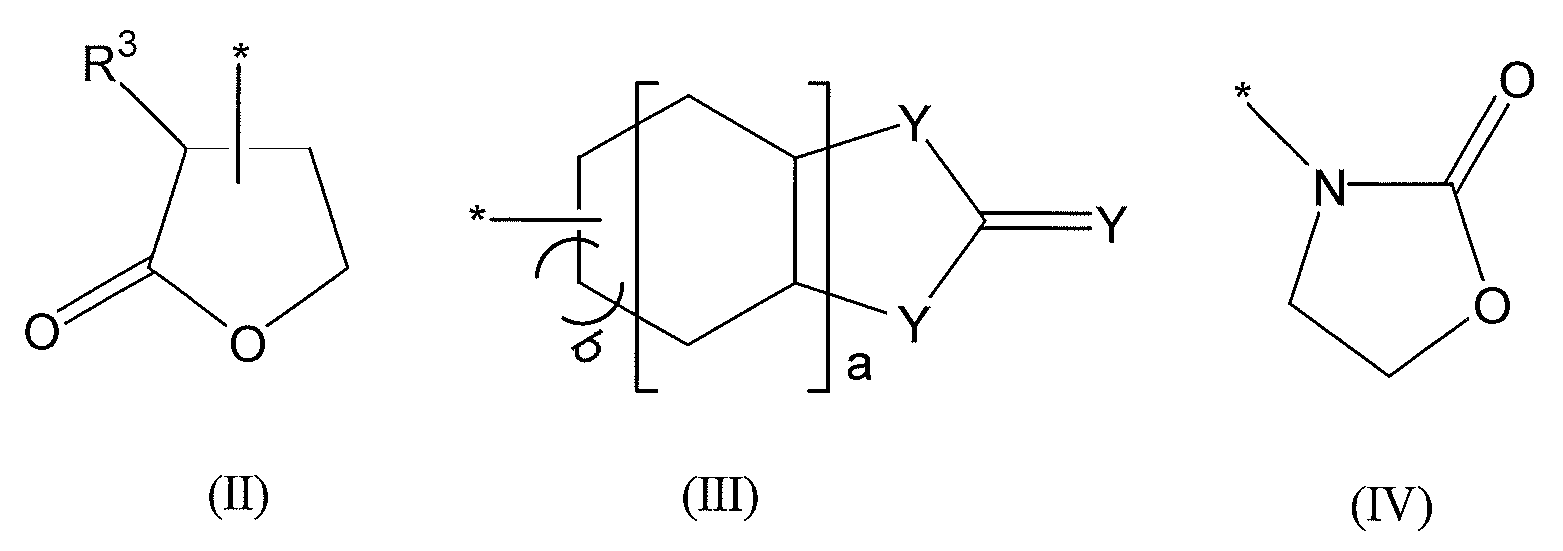
- R 2 is a group selected from the following formulas (II) to (IV)).
- R 3 is a hydrogen atom or an alkyl group having 1 to 4 carbon atoms
- Y may be the same or different from each other, is an oxygen atom or a sulfur atom, a is 0 or 1, and b Is an integer from 1 to 3. * indicates a bond.
- a gel polymer electrolyte obtained by crosslinking the electrolyte composition of [1] to [3].
- a transparent substrate, a transparent conductive film formed on the surface of the transparent substrate, and a conductive substrate provided at a position opposite to the transparent conductive film, the transparent conductive film and the conductive substrate A dye-sensitized solar cell having a porous semiconductor layer adsorbing a dye and an electrolyte, wherein the electrolyte comprises the electrolyte composition of [1] to [3] A dye-sensitized solar cell, characterized in that [6] The dye-sensitized solar cell according to [5], wherein the polymer electrolyte is a gel electrolyte obtained by infiltrating the electrolyte composition according to any one of the semiconductor films made of a porous material and heating. .
- the electrolyte composition of the present invention is characterized by containing a polymer compound containing a repeating unit represented by the formula (1), a pair of iodine and iodine compound or bromine and bromine compound, and an organic solvent, and a simple production process.
- a dye-sensitized solar cell that is excellent in photoelectric conversion characteristics, has little leakage of the electrolyte and the accompanying characteristic deterioration with time, has a higher short-circuit current density, and has high energy conversion efficiency.
- the electrolyte composition according to the present invention includes a polymer compound (A) containing a repeating unit represented by formula (1), a pair of iodine and iodine compound or a bromine and bromine compound (B), and an organic solvent. .
- A) Polymer Compound The polymer compound contains a repeating unit (A-1) represented by the following formula (1).
- R 1 is a hydrogen atom or a methyl group
- X is a single bond or a divalent linking group
- Examples of the divalent linking group include a divalent hydrocarbon group having 1 to 30 carbon atoms and a divalent hydrocarbon group having 1 to 30 carbon atoms having an oxygen atom or a sulfur atom.
- Examples of the divalent hydrocarbon group having 1 to 30 carbon atoms include an alkanediyl group having 1 to 30 carbon atoms and a cycloalkanediyl group having 3 to 30 carbon atoms.
- Examples thereof include an alkylene group having 1 to 3 carbon atoms and a cycloalkylene group having 3 to 8 carbon atoms. More specific examples include a methylene group, an ethylene group, a propylene group, a cyclohexylene group, and a cyclopentylene group.
- Examples of the divalent hydrocarbon group having 1 to 30 carbon atoms having an oxygen atom or a sulfur atom include an alkylene group having an ether or thioether bond having 2 or more carbon atoms. Specifically, —CH 2 - (O-CH 2) n -, - C 2 H 4 - (O-C 2 H 4) n - (. n is represents an integer of 1 to 10)) and the like.
- R 2 is a group selected from the following formulas (II) to (IV).
- R 3 is a hydrogen atom or an alkyl group having 1 to 4 carbon atoms.
- Y may be the same or different from each other, and is an oxygen atom or a sulfur atom, a is 0 or 1, and b is an integer of 1 to 3. * Indicates a bond, and the bond position is not particularly limited.
- Examples of the monomer that gives the formula (1) include the following (A) to (G).
- R 2 is preferably of formula (II) (specifically, (A) above) for the reason (higher energy conversion efficiency can be obtained). More preferably, R 1 is a methyl group. Further, the polymer compound may contain a structural unit (A-2) other than the structural unit (A-1) represented by the above formula (1).
- Examples of such structural units include the following.
- R 1 and X are the same as in the above formula (1).
- X 2 is a divalent hydrocarbon group which may have an ether bond. Specifically, —CH 2 —, —C 2 H 4 —, —CH 2 — (O—CH 2 ) n —, —C 2 H 4 — (O—C 2 H 4 ) n — and the like are shown. n is an integer of 1 to 10.
- R 4 represents a hydrogen atom, an alkyl group having 1 to 10 carbon atoms, an alkenyl group, an aryl group, an aralkyl group, —COR 6 or —SO 2 R 6
- R 6 represents an alkyl group having 1 to 10 carbon atoms or an alkenyl group
- the polymer compound preferably has a weight average molecular weight in the range of 1,000 to 100,000, preferably 3,000 to 50,000, more preferably 5,000 to 30,000. When the molecular weight is within this range, the viscosity of the electrolyte composition before gelation is low, and the electrolyte composition can be easily soaked into a semiconductor film made of a porous material, and high energy conversion efficiency can be obtained.
- the polymer compound is a copolymer of the structural unit (A-1) and the structural unit (A-2), and the structural unit (A-1) is included in the polymer compound in an amount of 5 to 95% by weight. It is desirable.
- the polymer compound is prepared by polymerizing a monomer represented by the following formula (A-1a) and, if necessary, (A-2a).
- the reaction is carried out in a solvent in the presence of a polymerization initiator.
- polymerization initiators can be used as the polymerization initiator.
- known polymerization initiators include azobis compounds, peroxides, hydroperoxides, redox catalysts, etc., such as potassium persulfate, ammonium persulfate, t-butyl peroctoate, benzoyl peroxide, isopropyl
- examples include percarbonate 2,4-dichlorobenzoyl peroxide, methyl ethyl ketone peroxide, cumene hydroperoxide, azobisisobutyronitrile, 2,2'-azobis (2-aminodipropane) hydrochloride, and the like.
- the heating polymerization temperature is preferably 40 to 150 ° C, more preferably 50 to 120 ° C.
- a polymerization solvent may be used.
- the polymerization solvent include alcohols (ethanol, methanol, isopropyl alcohol, t-butyl alcohol, t-amyl alcohol ethylene glycol, etc.), ketones (acetone, methyl ethyl ketone, cyclohexanone, etc.), water, esters (methyl acetate).
- the electrolyte composition of the present invention includes any one of a combination of I 2 and iodide and a combination of Br 2 and bromide as a redox pair (electrolyte).
- Metal bromides such as LiBr, NaBr, KBr, CsBr, and CaBr 2 as bromides
- metal iodides such as LiI, NaI, KI, CsI, and CaI 2 , or tetraalkylammonium iodide, pyridinium iodide, and imidazo Examples include iodine salts of quaternary ammonium compounds such as lithium iodide.
- the redox material LiI, NaI, KI, combinations of metal iodides and iodine, such as CaI 2, and LiBr, NaBr, preferably a combination of metal bromide and bromine, such as CaBr 2, among these, A combination of metal iodide and iodine is particularly preferred.
- organic solvent is preferably an aprotic solvent, and examples include cyclic esters, cyclic carbonates, cyclic ethers, chain carboxylic esters, heterocyclic compounds, chain carbonates. Examples thereof include esters, chain ethers, alcohols, polyhydric alcohols, nitrile compounds, sulfoxides and sulfolanes, and water. These solvents may be used alone or in combination of two or more.
- composition of Electrolyte Composition contains the above-described components and is usually
- the concentration of the redox couple (B) is usually in the range of 0.01 to 1.5 mol / liter, and more preferably in the range of 0.1 to 1.0 mol / liter.
- the polymer compound (A) is preferably 0.5% by weight or more and 80% by weight or less, more preferably 1.5% by weight or more and 50% by weight or less based on the total weight of the electrolyte composition. .
- the electrolyte composition of the present invention may contain a polyoxyalkylene glycol such as polyoxypropylene glyceryl ether.
- a polyoxyalkylene glycol such as polyoxypropylene glyceryl ether.
- Such polyoxyalkylene glycol can easily form a gel by reaction with the NCO group in the polymer compound.
- the added amount is preferably 0.1 to 10 parts by weight, preferably 1 to 5 parts by weight, based on 100 parts by weight of the electrolyte composition.
- the polymer component when it contains an isocyanate group, it may contain a crosslinking catalyst.
- Usable catalysts include organometallic catalysts and amine catalysts that are generally used in producing polyurethane foam.
- organometallic catalysts include stannous octoate such as tin, stannous oleate, dibutyltin dilaurate, and dibutyltin diacetate.
- amine catalysts include triethylamine, tributylamine, N-methylmorpholine, N-ethylmorpholine, pyridine, triethylenediamine and the like can be mentioned.
- the amount of the crosslinking catalyst used is usually in the range of 0.001 to 5 wt% with respect to the total weight of the electrolyte composition.
- the electrolyte composition according to the present invention can be prepared by mixing the above components.
- the dye-sensitized solar cell according to the present invention is A transparent substrate; a transparent conductive film formed on the surface of the transparent substrate; and a conductive substrate provided at a position opposite to the transparent conductive film. And a dye-sensitized solar cell having a porous semiconductor layer adsorbing a dye and an electrolyte, wherein the electrolyte is a polymer electrolyte made of the electrolyte composition.
- the light incident on the semiconductor layer excites the dye.
- the excited dye has high-energy electrons, which are transferred from the dye to the semiconductor conduction band and reach the conductive film by diffusion.
- the dye molecule is an oxidant. Electrons on the conductive layer return to the oxidized dye through the counter electrode and the electrolyte layer while working in the external circuit, and the dye is regenerated.
- the semiconductor film serves as the negative electrode of this battery.
- FIG. 1 shows an example of such a dye-sensitized solar cell according to the present invention.
- it has the transparent conductive film 12 on the surface of the transparent substrate 11, and has the porous semiconductor layer 13 which adsorb
- a counter electrode substrate 15 provided with an electrode layer 16 is provided so as to face the transparent electrode-equipped substrate 11 with a predetermined gap. Further, the side surfaces of the transparent substrate 11 and the counter electrode substrate 15 are sealed with a sealant 17 or the like, and the electrolyte layer 14 is provided in the gap between the electrode layer 16 and the porous semiconductor layer 13.
- the electrolyte layer is composed of the electrolyte composition.
- the electrolyte composition is a gel-like solid electrolyte, thereby significantly improving the effect of preventing deterioration of photoelectric conversion characteristics over time, and further, there is little deterioration of photoelectric conversion characteristics. The photoelectric conversion characteristics are improved.
- the substrate examples include a glass substrate, a plastic substrate (PP, PET, PEN, PC, etc.), a steel plate, and the like.
- the transparent substrate is made of a highly transparent material.
- the conductive substrate that forms a counter electrode with the transparent substrate may not be transparent, but may be made of a transparent substrate material.
- the transparent conductive film functioning as an electrode is not particularly limited.
- a transparent conductive film such as tin oxide, fluorine-doped tin oxide, zinc oxide and indium oxide, and ITO (indium-tin oxide) can be used.
- These electrodes can be formed by a method such as vacuum deposition or coating, and the film thickness and the like can be appropriately selected.
- the conductive substrate of the counter electrode is provided with a conductive metal film of metal (for example, platinum, gold, silver, copper, aluminum, rhodium, indium, etc.) as the conductive layer, but the transparent conductive film is provided. It may be done. Note that in the case where the conductive film can stand on its own, the conductive film itself can function as a conductive substrate. Furthermore, if a flexible material is used for the substrate and the electrode layer, a solar cell can be formed on the curved surface.
- the light incident surface of the solar cell is usually composed of a transparent substrate and a transparent conductive film.
- the counter electrode has a property of reflecting light.
- Examples of the metal oxide constituting the semiconductor layer include known semiconductors such as titanium oxide, zinc oxide, tungsten oxide, barium titanate, strontium titanate, and cadmium sulfide. Two or more kinds of these semiconductors can be mixed and used. Among these, titanium oxide is particularly preferable in terms of conversion efficiency, stability, and safety. Examples of such titanium oxides include anatase-type titanium oxide, rutile-type titanium oxide, amorphous titanium oxide, various titanium oxides such as metatitanic acid and orthotitanic acid, and oxide-containing titanium composites. One type or two or more types can be used as appropriate.
- the semiconductor layer can be in various forms such as particles and films, but a film-like semiconductor (semiconductor film) formed on a substrate is preferable.
- the semiconductor film is preferably porous in order to adsorb the dye and increase the contact area with the electrolyte.
- Such a semiconductor layer is usually formed on the surface of the conductive film as shown in FIG. 1, but may be provided on the surface of the conductive layer of the counter electrode.
- the thickness of the porous semiconductor film is not particularly limited, but is preferably about 0.5 to 20 ⁇ m from the viewpoints of permeability and conversion efficiency.
- the film-like porous semiconductor has a large specific surface area, specifically about 10 to 200 m 2 / g.
- the above-described particulate semiconductor single or compound semiconductor particles having an appropriate average particle diameter among commercially available ones, for example, an average particle diameter of about 1 nm to 500 nm can be used.
- the solvent used for suspending the semiconductor particles include glyme solvents such as ethylene glycol monomethyl ether, alcohols such as isopropyl alcohol, mixed solvents such as isopropyl alcohol / toluene, water, and the like. It is done.
- the above-described porous semiconductor film is dried and baked by appropriately adjusting the temperature, time, atmosphere, and the like according to the type of substrate and semiconductor particles used.
- the reaction is performed in the air or in an inert gas atmosphere within a temperature range of about 50 to 800 ° C. for about 10 seconds to 12 hours.
- This drying and baking may be performed only once at a single temperature, or may be performed twice or more by changing the temperature.
- the dye functions as a photosensitizer and has absorption in various visible light regions and infrared light regions.
- a carboxyl group, an alkoxy group, a hydroxyl group is contained in the dye molecule.
- Those having an interlock group such as a group, a hydroxyalkyl group, a sulfonic acid group, an ester group, a mercapto group, and a phosphonyl group are preferred.
- the interlock group supplies an electrical bond that facilitates electron transfer between the excited dye and the semiconductor conductor.
- the dye containing an interlock group include ruthenium bipyridine dyes, azo dyes, quinone dyes, quinone imine dyes, quinacridone dyes, squarylium dyes, cyanine dyes, merocyanine dyes, and triphenylmethane dyes.
- metal complex dyes and / or polymethine dyes disclosed in JP-A No. 2000-191729 can be preferably used.
- the dye to be used is a metal complex dye
- a ruthenium complex dye is preferable, and a dye represented by the following formula (II) is more preferable.
- Formula (II) (Y 1 ) p RuB a B b B c In the formula, p is from 0 to 2, preferably 2.
- Ru represents ruthenium.
- Y 1 is a ligand selected from Cl, SCN, H 2 O, Br, I, CN, NCO, and SeCN.
- B a , B b , and B c are each independently an organic ligand selected from the following B-1 to B-8.
- R a is a hydrogen atom, a halogen atom, an alkyl group substituted or unsubstituted with 1 to 12 carbon atoms (hereinafter referred to as C number), a substituted or unsubstituted aralkyl group with 7 to 12 carbon atoms, or C 6-12 represents a substituted or unsubstituted aryl group.
- the alkyl part of the alkyl group or aralkyl group may be linear or branched, and the aryl part of the aryl group or aralkyl group may be monocyclic or polycyclic (condensed ring, ring assembly). It may be.
- ruthenium complex dye used in the present invention examples include complexes described in US Pat. Nos. 4,927,721, 4,684,537, 5,084,365, 5,350,644, 5,463,057, 5,525,440 and JP-A-7-249790. Pigments.
- the dye used in the present invention is a polymethine dye
- a dye represented by the following formula (V) or formula (VI) is preferable.
- R b and R f each represent a hydrogen atom, an alkyl group, an aryl group, or a heterocyclic group
- R c to R e each represent a hydrogen atom or a substituent.
- R b to R f may combine with each other to form a ring.
- X 11 and X 12 each represent nitrogen, oxygen, sulfur, selenium, or tellurium.
- n 11 and n 13 each represents an integer of 0 to 2
- n 12 represents an integer of 1 to 6.
- the compound represented by the formula (III) may have a counter ion according to the charge of the whole molecule.
- the alkyl group, aryl group and heterocyclic group in the above may have a substituent.
- the alkyl group may be linear or branched, and the aryl group and heterocyclic group may be monocyclic or polycyclic (fused ring, ring assembly).
- the ring formed by R b to R f may have a substituent and may be a single ring or a condensed ring.
- Z a represents a nonmetallic atom group necessary for forming a nitrogen-containing heterocycle.
- R g is an alkyl group or an aryl group.
- Q represents a methine group or a polymethine group necessary for the compound represented by formula (IV) to form a methine dye.
- X 13 represents a charge balanced counter ion, and n 14 represents a number from 0 to 10 necessary for neutralizing the charge of the molecule.
- Nitrogen-containing heterocyclic ring formed by the above Z a may have a substituent, it may be a condensed ring may be a single ring.
- the alkyl group and the aryl group may have a substituent, the alkyl group may be linear or branched, and the aryl group may be monocyclic or polycyclic (fused ring, Ring assembly).
- adsorbing a dye functioning as a photosensitizer (hereinafter simply referred to as “dye”) on such a semiconductor layer for example, a semiconductor layer formed on a substrate is immersed in a solution in which the dye is dissolved. A method is mentioned.
- the solvent used for dissolving the dye examples include alcohols such as ethanol, ketones such as acetone, ethers such as diethyl ether and tetrahydrofuran, nitrogen compounds such as acetonitrile, halogenated aliphatic hydrocarbons such as chloroform, Examples thereof include aliphatic hydrocarbons such as hexane, aromatic hydrocarbons such as benzene, and esters such as ethyl acetate.
- the concentration of the dye in the solution can be appropriately adjusted depending on the kind of the dye and the solvent to be used. In order to improve the adsorption function, it is preferable that the concentration is somewhat high. For example, a concentration of 5 ⁇ 10 ⁇ 5 mol / liter or more is preferable.
- the temperature and pressure of the solution and atmosphere when the semiconductor is immersed in the solution in which the dye is dissolved are not particularly limited, and examples include room temperature and atmospheric pressure, and the immersion time is the dye used. It is preferable to adjust appropriately depending on the type of solvent, the concentration of the solution, and the like. In order to effectively perform the adsorption, the immersion may be performed under heating.
- the semiconductor layer may be provided on the transparent electrode or may be provided on the counter electrode.
- An electrolyte layer is provided in a gap between the semiconductor layer and the electrode or the transparent electrode.
- the electrolyte layer is made of a polymer electrolyte composed of the above electrolyte composition.
- the above electrolyte composition is liquid, it may be used as a liquid electrolyte as it is.
- the polymer compound is polymerized and crosslinked to be used as a gel polymer electrolyte.
- a counter electrode is provided on a semiconductor layer carrying a sensitizing dye with a predetermined gap therebetween, and a liquid electrolyte composition before gelation is inserted into the gap. Then, the method of making it gelatinize by heating is mentioned.
- a gelled electrolyte may be applied to the surface of the electrode or the semiconductor layer in advance, and the counter electrode may be bonded.
- the electrolyte composition before gelation penetrates into the pores of the porous semiconductor and is heated and polymerized / crosslinked, a gel electrolyte integrated with the semiconductor layer can be obtained. preferable.
- Such a solar cell manufacturing method can employ a known method without any particular limitation.
- a transparent conductive film is formed on the surface of a transparent substrate, a porous semiconductor layer such as titanium oxide is formed thereon, and a dye is adsorbed on the porous semiconductor layer.
- a conductive layer is formed on the substrate surface serving as a counter electrode, and the transparent substrate and the counter electrode substrate are overlaid so that the porous semiconductor layer and the conductive layer face each other.
- the side surface of the transparent substrate and the counter electrode substrate is sealed with an epoxy resin, the electrolyte composition is injected therebetween, and the electrolyte is gelled by heat sensing, whereby the dye-sensitized solar cell according to the present invention is obtained.
- Example 1 Synthesis of Polymer Compound (1) A three-necked flask containing 20 g of a polymerizable monomer represented by the following formula (I), 20 g of Karenz MOI (2-methacryloyloxyethyl isocyanate, Showa Denko), and 160 g of ⁇ -butyrolaclone as oil After heating to 60 ° C. with a bath, 1 g of 2,2′-azobisisobutyronitrile was added and reacted at 80 ° C. for 6 hours to obtain a polymer compound (1). The obtained polymer solution had a solid content of 20% by weight. Further, the weight average molecular weight of the obtained polymer (Mw) was 10,000.
- Mw weight average molecular weight of the obtained polymer
- the titanium oxide dispersion was applied to a conductive glass substrate with an area of 5 mm ⁇ 5 mm by a squeegee method and dried at 150 ° C. for 5 minutes to obtain a titanium oxide film.
- the film thickness of the obtained titanium oxide film was 10 ⁇ m.
- Ru complex dye N719 (Solaronix) was dissolved in n-butanol to obtain a dye solution having a concentration of 2 ⁇ 10 ⁇ 4 mol / liter.
- a PEN film with a titanium oxide film was immersed in this dye solution at room temperature for 24 hours to obtain a dye-sensitized photoelectrode to which a Ru dye was adsorbed.
- ARTON® manufactured by JSR, surface resistance value 5 ohm / sq
- a dye-sensitized photoelectrode and the counter electrode were bonded together by stacking a 50 ⁇ m thick high-milan tape between the dye-sensitized photoelectrode and the counter electrode substrate, followed by thermocompression bonding.
- the electrolyte composition 1 was injected from the electrolyte solution injection port opened in the counter electrode substrate by utilizing capillary action, and the injection port was sealed and left at 100 ° C. for 1 hour to gel the electrolyte solution.
- dye was adsorbed, a gel electrolyte, and a counter electrode film was produced, and the cell was produced.
- Example 2 A polymer compound (2) was obtained in the same manner as in Example 1 except that a polymerizable monomer represented by the following formula (II) was used instead of the compound of the formula (I).
- the obtained polymer solution had a solid content of 20% by weight. Further, the weight average molecular weight of the obtained polymer (Mw) was 12,000.
- an electrolyte composition (2) was synthesized in the same manner as in Example 1) to obtain a dye-sensitized solar cell.
- Example 3 A polymer compound (3) was obtained in the same manner as in Example 1 except that a polymerizable monomer represented by the following formula (III) was used.
- the obtained polymer solution had a solid content of 20% by weight. Further, the weight average molecular weight of the obtained polymer (Mw) was 10,000.
- an electrolyte composition (3) was synthesized in the same manner as in Example 1) to obtain a dye-sensitized solar cell.
- Example 4 A polymer compound (4) was obtained in the same manner as in Example 1 except that a polymerizable monomer represented by the following formula (IV) was used. The solid content of the obtained polymer solution was 20%. Further, the weight average molecular weight of the obtained polymer (Mw) was 11,000.
- an electrolyte composition (4) was synthesized in the same manner as in Example 1 to obtain a dye-sensitized solar cell.
- an electrolyte composition (5) was synthesized in the same manner as in Example 1) to obtain a dye-sensitized solar cell.
- Comparative Example 2 A three-necked flask containing 20 g of terahydrofurfuryl methacrylate (Kyoeisha Chemical), 20 g of Karenz MOI (manufactured by Showa Denko) and 160 g of ⁇ -butyrolaclone was heated to 60 ° C. in an oil bath, and 2,2′-azobisiso 1 g of butyronitrile was added and reacted at 80 ° C. for 6 hours to obtain a polymer compound (6).
- the obtained polymer solution had a solid content of 20% by weight. Further, the weight average molecular weight of the obtained polymer (Mw) was 10,000.
- an electrolyte composition (6) was synthesized in the same manner as in Example 1) to obtain a dye-sensitized solar cell.
- Comparative Example 3 A three-necked flask containing 40 g of Karenz MOI (manufactured by Showa Denko) and 160 g of ⁇ -butyrolaclone was heated to 60 ° C. in an oil bath, and then 1 g of 2,2′-azobisisobutyronitrile was added at 80 ° C. The polymer was reacted for 6 hours to obtain a polymer compound (7) composed of a homopolymer of Karenz MOI. The solid content of the obtained polymer solution was 20%. Further, the weight average molecular weight of the obtained polymer (Mw) was 9,000.
- an electrolyte composition (8) was synthesized in the same manner as in Example 1 to obtain a dye-sensitized solar cell.
- an electrolyte composition (9) was synthesized in the same manner as in Example 1 to obtain a dye-sensitized solar cell.
- the solar cells of Examples 1 to 4 were prepared by using the polymer composition containing the repeating unit represented by the formula (1) and the polymer composition containing the polymer compound other than the formula (1). It can be seen that a short-circuit current density higher than that of the solar cell made of a material and Comparative Examples 1 to 5 is obtained and the energy conversion efficiency is high. Moreover, the solar cell of Example 1 has an energy conversion efficiency of about 93% as compared with Comparative Example 6, which is a solar cell composed only of a liquid electrolyte that does not contain a polymer compound. It is possible to obtain conversion efficiencies exceeding%.
Landscapes
- Engineering & Computer Science (AREA)
- Power Engineering (AREA)
- Chemical & Material Sciences (AREA)
- Chemical Kinetics & Catalysis (AREA)
- Electrochemistry (AREA)
- Microelectronics & Electronic Packaging (AREA)
- Photovoltaic Devices (AREA)
- Hybrid Cells (AREA)
- Conductive Materials (AREA)
Abstract
[課題] 光電変換特性に優れ、電解液漏洩およびそれに伴う経時での特性劣化が少なく、より高い短絡電流密度が得られ、エネルギー変換効率が高い色素増感型太陽電池を提供可能な電解質組成物を提供する。 [解決手段] 下記式(1)で示される繰り返し単位を含む高分子化合物(A)、ヨウ素とヨウ素化合物あるいは臭素と臭素化合物の一対(B)、および有機溶剤を含むことを特徴とする電解質組成物。(式(1)中、R1は水素原子又はメチル基であり、Xは単結合または2価の結合基であり、R2は式(II)~(IV)から選ばれる基である。式(II)~(IV)中、R3は水素原子又は炭素数1~4のアルキル基であり、Yは、互いに同一でも異なっていてもよく、酸素原子または硫黄原子であり、aは0または1であり、bは1~3の整数である。また、*は結合手を示す。)
Description
本発明は、電解質組成物及びこの電解質組成物を用いた色素増感型太陽電池に関するものである。
太陽光発電は単結晶シリコン太陽電池、多結晶シリコン太陽電池、アモルファスシリコン太陽電池、テルル化カドミウムやセレン化インジウム銅等の化合物太陽電池が実用化もしくは主な研究開発の対象となっているが、普及させる上で製造コスト、原材料確保、エネルギーペイバックタイムが長い等の問題点を克服する必要がある。一方、大面積化や低価格化を指向した有機材料を用いた太陽電池もこれまでにも多く提案されているが、変換効率が低く、耐久性も悪いという問題があった。
こうした状況の中で、色素によって増感された半導体微粒子を用いた色素増感型太陽電池は、有機系太陽電池の中で高変換効率を示すため、広く注目されている。
このような色素増感型太陽電池では、対極との電気的接続を電解質溶液(電解液)によって行っている。このような電解液は、長期にわたって使用すると電解液の枯渇により光電変換効率が著しく低下したり、素子として機能しなくなることが懸念されている。また、液相の電解液を使用するので、液漏れを起こすことも懸念されていた。
そこで、このような問題点を解消するために、色素増感型太陽電池に使用される電解液層を固体化することが提案されている。電解液層の固体化方法としては、電解質とともに重合性のモノマーを使用し、モノマーを重合することで高分子化合物として、固体化する方法が提案されている(特開平8-236165号公報、特許文献1)。
リチウムイオン電池などの二次電池には高分子固体電解質として、通常アクリル系重合体が使用されていた。たとえば、特許文献2(特開平3-177410号公報)にはアクリル系多官能モノマーを使用した高分子固体電解質が例示され、特許文献3(特開平6-223842号公報)には、ビニレンカーボネート系モノマーを使用した高分子固体電解質が開示されていた。
また、特許文献4(特開2002-289273号公報)には、太陽電池用電解質として、イソシアネート基を有する化合物とカルボキシル基および/またはヒドロキシル基を有する化合物とが架橋してなる網目構造体を用いることが開示されている。
さらに、特許文献5(特許番号4360569号)には、太陽電池用電解質として、水酸基および/またはカルボキシル基を含有するポリマーとイソシアネート基を2個以上含有する化合物を添加して架橋反応するゲル状電解質が提案されている。
特許文献2および3にあるような環状構造を有する(メタ)アクリレート由来の高分子化合物を使用した二次電池は知られているものの、実際の色素型太陽電池に適用したものはなく、その効果は全く不明である。
また、特許文献4および5のように、従来から提案されていた、重合体成分を含むゲル状電解質では、イオン伝導度が低いため、重合体成分を添加することで、短絡電流密度が減少し、エネルギー変換効率が低下するという問題もあった。
上記問題点を解決すべく鋭意検討した結果、特定の環状構造を有する(メタ)アクリレート由来の高分子化合物を、ヨウ素とヨウ素化合物あるいは臭素と臭素化合物の一対と組合わせることで、高いイオン伝導度を有するゲル電解質が得られることを見出し、短絡電流密度が減少することなく、高いエネルギー変換効率が得られることを見出した。
本発明の構成は以下の通りである。
[1]下記式(1)で示される繰り返し単位を含む高分子化合物(A)、ヨウ素とヨウ素化合物あるいは臭素と臭素化合物の一対(B)、および有機溶剤を含むことを特徴とする電解質組成物。
[1]下記式(1)で示される繰り返し単位を含む高分子化合物(A)、ヨウ素とヨウ素化合物あるいは臭素と臭素化合物の一対(B)、および有機溶剤を含むことを特徴とする電解質組成物。

(式(1)中、R1は水素原子又はメチル基であり、Xは単結合または2価の結合基であり、R2は下記式(II)~(IV)から選ばれる基である。

(式中、R3は水素原子又は炭素数1~4のアルキル基であり、Yは、互いに同一でも異なっていてもよく、酸素原子または硫黄原子であり、aは0または1であり、bは1~3の整数である。また、*は結合手を示す。)
[2]前記高分子化合物の重量平均分子量が1,000~100,000である[1]の電解質組成物。
[3]前記高分子化合物中に、上記式(1)で示される構成単位が5~95重量%含まれていることを特徴とする請求項1に記載の電解質組成物。
[4]前記[1]~[3]の電解質組成物が架橋してなるゲル状の高分子電解質。
[5]透明基板と、この透明基板の表面に形成された透明導電膜と、この透明導電膜に相対向する位置に設けられた導電性基板とを有し、前記透明導電膜と導電性基板との間に、色素を吸着した多孔性半導体層と、電解質とを有する色素増感型太陽電池であって、前記電解質が、前記[1]~[3]の電解質組成物からなる高分子電解質であることを特徴とする色素増感型太陽電池。
[6]前記高分子電解質が、多孔性物質からなる半導体膜中にのいずれかに記載の電解質組成物を浸透させ、加熱によって得られたゲル状電解質である[5]の色素増感太陽電池。
本発明の電解質組成物は、式(1)で示される繰り返し単位を含む高分子化合物、ヨウ素とヨウ素化合物あるいは臭素と臭素化合物の一対、および有機溶剤を含むことが特徴であり、作製工程が簡素で、光電変換特性に優れ、電解液漏洩およびそれに伴う経時での特性劣化が少ない上、より高い短絡電流密度が得られ、エネルギー変換効率が高い色素増感型太陽電池が得られる。
以下、本発明について、説明する。
電解質組成物
本発明にかかる電解質組成物は、式(1)で示される繰り返し単位を含む高分子化合物(A)、ヨウ素とヨウ素化合物あるいは臭素と臭素化合物の一対(B)、および有機溶剤を含む。
(A)高分子化合物
高分子化合物は下記式(1)で表される繰り返し単位(A-1)を含む。
本発明にかかる電解質組成物は、式(1)で示される繰り返し単位を含む高分子化合物(A)、ヨウ素とヨウ素化合物あるいは臭素と臭素化合物の一対(B)、および有機溶剤を含む。
(A)高分子化合物
高分子化合物は下記式(1)で表される繰り返し単位(A-1)を含む。

式(1)中、R1は水素原子又はメチル基であり、Xは単結合または2価の結合基である。
2価の結合基としては、炭素数1~30の2価の炭化水素基、酸素原子ないし硫黄原子を有する炭素数1~30の2価の炭化水素基を挙げることができる。炭素数1~30の2価の炭化水素基としては、炭素数1~30のアルカンジイル基、炭素数3~30のシクロアルカンジイル基、などを挙げることができ、具体的には、炭素数1~3のアルキレン基、炭素数3~8のシクロアルキレン基を挙げることができ、より具体的には、メチレン基、エチレン基、プロピレン基、シクロヘキシレン基、シクロペンチレン基が例示される。
また、酸素原子ないし硫黄原子を有する炭素数1~30の2価の炭化水素基としては、炭素数2以上のエーテルないしチオエーテル結合を有するアルキレン基を挙げることができ、具体的には-CH2-(O-CH2)n-、-C2H4-(O-C2H4)n-(nは1~10の整数を示す。))などを挙げることができる。
R2は下記式(II)~(IV)から選ばれる基である。
式中、R3は水素原子又は炭素数1~4のアルキル基である。Yは、互いに同一であっても異なっていてもよく、酸素原子または硫黄原子であり、aは0または1であり、bは1~3の整数である。また、*は結合手を示し、結合位置は特に制限されない。
式(1)を与える単量体としては、以下(A)~(G)のものが例示される。

このうち、R2が式(II)のもの(具体的には上記(A))が、(より高いエネルギー変換効率が得られる)という理由で好ましい。さらにR1がメチル基のものがより好ましい。さらに、高分子化合物は、上記式(1)で示される構成単位(A-1)以外の構成単位(A-2)が含まれていてもよい。
かかる構成単位としては、以下のものが例示される。

上記式中、R1、Xは上記式(1)と同様である。
X2は、エーテル結合を有していてもよい2価の炭化水素基である。具体的に-CH2-、-C2H4-、-CH2-(O-CH2)n-、-C2H4-(O-C2H4)n-などを示す。nは1~10の整数である。
またX3は、エーテル結合を有していてもよい3価の炭化水素基である。具体的に-CH=、-C2H3=、=CH-(O-CH2)n-、=C2H3-(O-C2H4)n-などを示す。nは1~10の整数である。
R4は水素原子、炭素数1~10のアルキル基、アルケニル基、アリール基、アラルキル基、-COR6又は-SO2R6を表し、R6は炭素数1~10のアルキル基、アルケニル基、アリール基又はアラルキル基、NCO(イソシアネート)基などである。このうち、電解質の架橋を促進するためには、イソシアネート基を有するものを使用することが望ましい。
前記高分子化合物は、重量平均分子量が1,000~100,000、好ましくは3,000~50,000、さらに好ましくは5,000~30,000の範囲にあることが望ましい。かかる分子量範囲にあると、ゲル化前の電解質組成物の粘性が低く、多孔性物質からなる半導体膜中へ容易に染み込むことができ、高いエネルギー変換効率が得られる。
高分子化合物は、構成単位(A-1)と構成単位(A-2)の共重合物であり、構成単位(A-1)が、高分子化合物中に5~95重量%含まれていることが望ましい。
高分子化合物は、下記式(A-1a)および必要に応じて(A-2a)で示されるモノマーを重合することによって調製される。


反応は溶媒中で、重合開始剤の存在下に行なわれる。
重合開始剤としては公知の重合開始剤が使用でき、例としてはアゾビス化合物,パーオキシド、ハイドロパーオキシド、レドックス触媒など、例えば過硫酸カリウム、過硫酸アンモニウム、t-ブチルパーオクトエイト、ベンゾイルパーオキシド、イソプロピルパーカーボネート2,4-ジクロロベンゾイルパーオキシド、メチルエチルケトンパーオキシド、クメンハイドロパーオキシド、アゾビスイソブチロニトリル、2,2′-アゾビス(2-アミノジプロパン)ハイドロクロリドなどが挙げられる。
加熱重合温度は40~150℃が好ましく、更に好ましくは50~120℃である。
本発明に用いられる高分子化合物を調製する際には、重合溶媒を用いてもよい。重合溶媒の具体例としては、アルコール類(エタノール、メタノール、イソプロピルアルコール、t-ブチルアルコール、t-アミルアルコールエチレングリコールなど)、ケトン類(アセトン、メチルエチルケトン、シクロヘキサノンなど)、水、エステル類(酢酸メチル、酢酸エチル、酢酸ブチルなど)、芳香族類(ベンゼン、トルエン、キシレン、ニトロベンゼン、p-クレゾールなど)、ハロゲン系(ジクロロメタン、1,2-ジクロロメタン、クロロホルム、テトラクロロエチレン、テトラクロロエタンなど)などが使用される。
さらに、重合溶媒として、エチレンカーボネート、プロピレンカーボネート、ビニレンカーボネート、エチルカーボネート、プロピルカーボネート、4,5-ジメチル-1,3-ジオキソラン-2-オン、4-メトキシメチル-1,3-ジオキソラン-2-オン、4,5-ジメトキシメチル-1,3-ジオキソラン-2-オン、4-ヒドロキシメチル-1,3-ジオキソラン-2-オン、4-エトキシメチル-1,3-ジオキソラン-2-オン、4-メトキシエチル-1,3-ジオキソラン-2-オン、4-クロロ-5-メトキシメチル-1,3-ジオキソラン-2-オン、4-アセトキシメチル-1,3-ジオキソラン-2-オン、1,3-ジオキサン-2-オン、フェニレンカーボネートなどのカーボネート類、γ-ブチロラクトン、γ-バレロラクトン、γ-カプリロラクトン、クロトラクトン、γ-カプロラクトン、δ-バレロラクトンなどのラクトン類、テトラヒドロフラン、2-メチルテトラヒドロフラン、3-メチルテトラヒドロフラン、2,5-ジメチルテトラヒドロフラン、テトラヒドロピラン、2-メチルテトラヒドロピラン、3-メチルテトラヒドロピラン、ジオキソラン、2-メチルジオキソラン、4-メチルジオキソラン、1,3-ジオキサン、1,4-ジオキサン、2-メチル-1,4-ジオキサンなどの環状エーテル類、ジエチルエーテル、ジプロピルエーテル、エチルプロピルエーテル、1,2-ジメトキシエタンなどのエーテル類、アセトニトリル、プロピオニトリル等のニトリル類、ギ酸メチル、ギ酸エチルなどのエステル類、N,N-ジメチルホルムアミド、N,N-ジメチルアセトアミドなどアミド類があげられる。さらに他に、ニトロメタン、塩化チオニル、スルホランなどを好適に用いることができる。これらの重合溶媒は1種又は2種以上を混合して用いてもよい。
(B)酸化還元対
本発明の電解質組成物は、酸化還元対(電解質)として、I2とヨウ化物の組み合わせ、Br2と臭化物の組み合わせのいずれか一対を含む。
(B)酸化還元対
本発明の電解質組成物は、酸化還元対(電解質)として、I2とヨウ化物の組み合わせ、Br2と臭化物の組み合わせのいずれか一対を含む。
臭化物としてはLiBr、NaBr、KBr、CsBr、CaBr2 などの金属臭化物、ヨウ化物としてはLiI、NaI、KI、CsI、CaI2 などの金属ヨウ化物、あるいはテトラアルキルアンモニウムヨーダイド、ピリジニウムヨーダイド、イミダゾリウムヨーダイドなど4級アンモニウム化合物のヨウ素塩などが例示される。
これらの中でも、酸化還元体としては、LiI、NaI、KI、CaI2などの金属ヨウ化物とヨウ素の組み合わせ、およびLiBr、NaBr、CaBr2などの金属臭化物と臭素の組み合わせが好ましく、これらの中でも、金属ヨウ化物とヨウ素の組み合わせが特に好ましい。
さらに本発明では電解質として、I2とヨウ化物、Br2と臭化物以外に、フェロシアン酸塩-フェリシアン酸塩やフェロセン-フェリシニウムイオンなどの金属錯体、ポリ硫化ナトリウム、アルキルチオール-アルキルジスルフィドなどのイオウ化合物、ビオロゲン色素、ヒドロキノン-キノンなどを用いることができる。
(C)有機溶媒
有機溶媒は非プロトン性の溶媒であることが好ましく、例としては、環状エステル類、環状炭酸エステル類、環状エーテル類、鎖状カルボン酸エステル類、複素環化合物、鎖状炭酸エステル類、鎖状エーテル類、アルコール類、多価アルコール類、ニトリル化合物、スルフォキシドやスルフォラン類、水などが挙げられる。これらの溶媒は1種類を用いても、2種類以上用いてもよい。
(C)有機溶媒
有機溶媒は非プロトン性の溶媒であることが好ましく、例としては、環状エステル類、環状炭酸エステル類、環状エーテル類、鎖状カルボン酸エステル類、複素環化合物、鎖状炭酸エステル類、鎖状エーテル類、アルコール類、多価アルコール類、ニトリル化合物、スルフォキシドやスルフォラン類、水などが挙げられる。これらの溶媒は1種類を用いても、2種類以上用いてもよい。
具体的には、エチレンカーボネート、プロピレンカーボネート、3-メチル-2-オキサゾリジノン、ジオキサン、ジエチルエーテル、エチレングリコールジアルキルエーテル、プロピレングリコールジアルキルエーテル、ポリエチレングリコールジアルキルエーテル、ポリプロピレングリコールジアルキルエーテル、メタノール、エタノール、エチレングリコールモノアルキルエーテル、プロピレングリコールモノアルキルエーテル、ポリエチレングリコールモノアルキルエーテル、ポリプロピレングリコールモノアルキルエーテル、エチレングリコール、プロピレングリコール、ポリエチレングリコール、ポリプロピレングリコール、グリセリン、アセトニトリル、グルタロジニトリル、メトキシアセトニトリル、プロピオニトリル、ベンゾニトリル、ジメチルスルフォキシド、スルフォラン、γ-ブチロラクトン、水などが挙げられる。
電解質組成物の組成
本発明にかかる組成物は、上記した各成分を含み、通常、液状である。
電解質組成物の組成
本発明にかかる組成物は、上記した各成分を含み、通常、液状である。
上記酸化還元対(B)の濃度は、通常0.01~1.5モル/リットルの範囲であり、中でも0.1~1.0モル/リットルの範囲が好ましい。
また、重合体化合物(A)は、電解質組成物の総重量に対し0.5重量%以上80重量%以下であることが好ましく、さらに1.5重量%以上50重量%以下であることが好ましい。
本発明の電解質組成物には、上記以外に、ポリオキシプロピレングリセリルエーテルなどのポリオキシアルキレングリコールが含まれていてもよい。このようなポリオキシアルキレングリコールは高分子化合物中のNCO基との反応により容易にゲルを形成することができる。またその添加量は、電解質組成物100重量部に対し、0.1~10重量部、好ましくは1~5重量部の量で含まれることが望ましい。
また、重合体成分に、イソシアネート基が含まれている場合、架橋触媒を含んでいてもよい。使用可能な触媒としては、一般的にポリウレタンフォームを製造する際に用いられるような、有機金属触媒やアミン触媒が挙げられる。具体的には、有機金属触媒の例として、錫などのスタナスオクトエート、スタナスオレエート、ジブチルチンジラウレート、ジブチルチンジアセテートなど、アミン触媒の例として、トリエチルアミン、トリブチルアミン、N-メチルモルホリン、N-エチルモルホリン、ピリジン、トリエチレンジアミンなどが挙げられる。
架橋触媒の使用量は電解質組成物の総重量に対して、通常は0.001~5wt%の範囲であればよい。
本発明のかかる電解質組成物は、上記各成分を混合すれば調製できる。
[色素増感太陽電池]
本発明にかかる色素増感型太陽電池は、
透明基板と、この透明基板の表面に形成された透明導電膜と、この透明導電膜に相対向する位置に設けられた導電性基板とを有し、前記透明導電膜と導電性基板との間に、色素を吸着した多孔性半導体層と、電解質とを有する色素増感型太陽電池であって、前記電解質が、前記電解質組成物からなる高分子電解質であることを特徴とする。
本発明にかかる色素増感型太陽電池は、
透明基板と、この透明基板の表面に形成された透明導電膜と、この透明導電膜に相対向する位置に設けられた導電性基板とを有し、前記透明導電膜と導電性基板との間に、色素を吸着した多孔性半導体層と、電解質とを有する色素増感型太陽電池であって、前記電解質が、前記電解質組成物からなる高分子電解質であることを特徴とする。
半導体層に入射した光は色素を励起する。励起色素はエネルギーの高い電子を有しており、この電子が色素から半導体の伝導帯に渡され、さらに拡散によって導電膜に到達する。この時色素分子は酸化体となっている。導電層上の電子が外部回路で仕事をしながら対極および電解質層を経て色素酸化体に戻り、色素が再生する。半導体膜はこの電池の負極として働く。
このような本発明にかかる色素増感型太陽電池の一態様例を図1に示す。図1では、透明基板11の表面に透明導電膜12を有し、その上に色素を吸着した多孔性半導体層13を有する。この透明電極付基板11と所定の間隙をもって対向するように、電極層16が設けられた対極基板15が設けられる。さらに、透明基板11と対極基板15の側面を封止剤17などで封止され、電極層16と多孔性半導体層13間にの間隙に電解質層14が設けられる。
本発明では、電解質層が、前記電解質組成物から構成される。なお、電解質層では電解質組成物が、ゲル状固体電解質となっており、これにより経時による光電変換特性の劣化を防止する効果が格段に向上し、さらには、光電変換特性の劣化が少なく、さらに光電変換特性が向上している。
基板としては、例えば、ガラス基板、プラスチック基板(PP、PET、PEN、PCなど)、鋼板などが挙げられる。このうち、透明基板としては、透明性の高い材料からなるものが使用される。また、透明基板と対極をなす導電性基板は、透明でなくともよいが、同様に透明な基板材料からなるものであってもよい。
電極として機能する透明導電膜は、特に限定されるものではないが、例えば酸化錫、フッ素がドープされた酸化錫、酸化亜鉛および酸化インジウム、ITO(インジウム-錫酸化物)などの透明導電膜が好ましい。これら電極は真空蒸着や塗布等の方法で形成可能であり、膜厚等は適宜選択することができる。また、対極の導電性基板には、導電層として、金属(例えば白金、金、銀、銅、アルミニウム、ロジウム、インジウム等)の導電性金属膜が設けられているが、前記透明導電膜が設けられていてもよい。なお、導電膜が自立可能である場合、導電膜自体を導電性基板として機能させることも可能である。さらに、基板および電極層に可撓性の素材を用いれば、曲面の上に太陽電池を構成することもできる。
半導体層に光が到達するためには、通常、太陽電池の光入射面が透明基板と透明導電膜で構成される。この場合対極は光を反射する性質を有することがさらに好ましい。
半導体層を構成する金属酸化物としては、酸化チタン、酸化亜鉛、酸化タングステン、チタン酸バリウム、チタン酸ストロンチウム、硫化カドミウムなどの公知の半導体が挙げられる。これらの半導体は、2種類以上を混合して用いることもできる。これらの中でも、変換効率、安定性、安全性の点から酸化チタンが特に好ましい。このような酸化チタンの例としては、アナターゼ型酸化チタン、ルチル型酸化チタン、無定形酸化チタン、メタチタン酸、オルソチタン酸などの種々の酸化チタン、含酸化チタン複合体などが挙げられる、これらの1種類又は2種類以上が適宜使用可能である。
半導体層は、粒子状、膜状など種々の形態のものを用いることができるが、基板上に形成された膜状の半導体(半導体膜)が好ましい。特に、半導体膜は、色素を吸着し、また電解質と接触面積を多くするために多孔性となっていることが好ましい。
かかる半導体層は、通常、図1に示すように導電膜表面に形成されるが、対極の導電層表面に設けられていてもよい。
多孔性半導体膜状を基板(電極)上に形成する方法としては、公知の種々の方法を使用することができる。
具体的には、(1)基板上に半導体粒子を含有する懸濁液を塗布し、乾燥・焼成する方法、(2)基板上に所望の原料ガスを用いたCVD法またはMOCVD法などにより半導体膜を成膜する方法、(3)原料固体を用いたPVD法、蒸着法、スパッタリング法またはゾル-ゲル法などにより半導体膜を形成する方法、および、(4)電気化学的酸化還元反応により形成する方法などが挙げられる。
多孔性半導体膜の膜厚は、特に限定されるものではないが、透過性、変換効率などの観点より、0.5~20μm程度が望ましい。また変換効率を向上させるためには、膜状の多孔性半導体に、後述する色素をより多く吸着させることが必要である。このために、膜状の多孔性半導体は比表面積が大きなものが望ましく、具体的には10~200m2/g程度が好ましい。
上述の粒子状の半導体としては、市販されているもののうち適当な平均粒径、例えば1nm~500nm程度の平均粒径を有する単一または化合物半導体の粒子などが使用可能である。また、この半導体粒子を懸濁させるために使用される溶媒の例としては、エチレングリコールモノメチルエーテルなどのグライム系溶媒、イソプロピルアルコールなどのアルコール系、イソプロピルアルコール/トルエンなどの混合溶媒、水などが挙げられる。
上述の多孔性半導体膜の乾燥および焼成は、使用する基板や半導体粒子の種類により、温度、時間、雰囲気などを適宜調整して行う。一般的な例では、大気下または不活性ガス雰囲気下、50~800℃程度の温度範囲内で、10秒から12時間程度行う。この乾燥および焼成は、単一の温度で1回のみ行ってもよく、または温度を変化させて2回以上行うこともできる。
色素は光増感剤として機能し、種々の可視光領域および赤外光領域に吸収を持つものであって、半導体層に強固に吸着させるために、色素分子中にカルボキシル基、アルコキシ基、ヒドロキシル基、ヒドロキシアルキル基、スルホン酸基、エステル基、メルカプト基、ホスホニル基などのインターロック基を有するものが好ましい。
インターロック基は、励起状態の色素と半導体の導電体との間の電子移動を容易にする電気的結合を供給するものである。これらインターロック基を含有する色素としては、例えば、ルテニウムビピリジン系色素、アゾ系色素、キノン系色素、キノンイミン系色素、キナクリドン系色素、スクアリリウム系色素、シアニン系色素、メロシアニン系色素、トリフェニルメタン系色素、キサンテン系色素、ポリフィリン系色素、フタロシアニン系色素、ベリレン系色素、インジゴ系色素、ナフタロシアニン系色素などが挙げられる。
また、本発明では特開2000-191729号公報に開示された金属錯体色素および/またはポリメチン色素を好適に使用することができる。使用する色素が金属錯体色素の場合、ルテニウム錯体色素が好ましく、さらに下記式(II)で表される色素が好ましい。
式(II) (Y1)pRuBaBbBc
式中、pは0~2であり、好ましくは2である。Ruはルテニウムを表す。Y1はCl、SCN、H2O、Br、I、CN、NCO、およびSeCNから選択される配位子である。Ba、Bb、Bcはそれぞれ独立に以下のB-1~B-8から選択される有機配位子である。
式(II) (Y1)pRuBaBbBc
式中、pは0~2であり、好ましくは2である。Ruはルテニウムを表す。Y1はCl、SCN、H2O、Br、I、CN、NCO、およびSeCNから選択される配位子である。Ba、Bb、Bcはそれぞれ独立に以下のB-1~B-8から選択される有機配位子である。

ここで、Raは水素原子、ハロゲン原子、炭素原子数(以下C数という)1~12個で置換もしくは無置換のアルキル基、C数7~12個で置換もしくは無置換のアラルキル基、またはC数6~12個で置換もしくは無置換のアリール基を表す。上記のアルキル基、アラルキル基のアルキル部分は直鎖状であっても分岐状であってもよく、アリール基、アラルキル基のアリール部分は単環であっても多環(縮合環、環集合)であってもよい。
本発明に用いられるルテニウム錯体色素としては、例えば、米国特許4927721号、同4684537号、同5084365号、同5350644号、同5463057号、同5525440号および特開平7-249790号明細書に記載の錯体色素が挙げられる。
本発明に使用する色素がポリメチン色素である場合、下記式(V)または式(VI)で表される色素が好ましい。

式中、RbおよびRfは各々水素原子、アルキル基、アリール基、または複素環基を表し、Rc~Reは各々水素原子または置換基を表す。Rb~Rfは互いに結合して環を形成してもよい。X11およびX12は各々窒素、酸素、硫黄、セレン、テルルを表す。n11およびn13は各々0~2の整数を表し、n12は1~6の整数を表す。式(III)で表される化合物は分子全体の電荷に応じて対イオンを有してもよい。
上記におけるアルキル基、アリール基、複素環基は、置換基を有していてもよい。アルキル基は直鎖であっても分岐鎖であってもよく、アリール基、複素環基は、単環でも、多環(縮合環、環集合)であってもよい。またRb~Rfによって形成される環は、置換基を有していてもよく、単環であっても縮合環であってもよい。

式中、Zaは含窒素複素環を形成するに必要な非金属原子群を表す。Rgはアルキル基またはアリール基である。Qは式(IV)で表される化合物がメチン色素を形成するのに必要なメチン基またはポリメチン基を表す。X13は電荷均衡対イオンを表し、n14は分子の電荷を中和するのに必要な0以上10以下の数を表す。
上記のZaで形成される含窒素複素環は置換基を有していてもよく、単環であっても縮合環であってもよい。また、アルキル基、アリール基は置換基を有していてもよく、アルキル基は直鎖であっても分岐鎖であってもよく、アリール基は単環であっても多環(縮合環、環集合)であってもよい。
かかる半導体層上に光増感剤として機能する色素(以下、単に「色素」と記す。)を吸着させる方法としては、例えば基板上に形成された半導体層を、色素を溶解した溶液に浸漬する方法が挙げられる。
色素を溶解するために用いる溶媒の例としては、エタノールなどのアルコール系、アセトンなどのケトン系、ジエチルエーテル、テトラヒドロフランなどのエーテル類、アセトニトリルなどの窒素化合物、クロロホルムなどのハロゲン化脂肪族炭化水素、ヘキサンなどの脂肪族炭化水素、ベンゼンなどの芳香族炭化水素、酢酸エチルなどのエステル類などが挙げられる。溶液中の色素濃度は、使用する色素および溶媒の種類により適宜調整することができ、吸着機能を向上させるためには、ある程度高濃度である方が好ましい。例えば、5×10⁻⁵モル/リットル以上の濃度が好ましい。
色素を溶解した溶液中に半導体を浸漬する際の、溶液および雰囲気の温度および圧力は特に限定されるものではなく、例としては室温程度かつ大気圧下が挙げられ、浸漬時間は、使用する色素、溶媒の種類、溶液の濃度などにより適宜調整することが好ましい。なお、吸着を効果的に行うには加熱下にて浸漬を行えばよい。
なお、半導体層は、透明電極上に設けられていてもよく、対極の電極上に設けられていてもよい。
かかる半導体層と、電極ないし透明電極の間の空隙に、電解質層が設けられる。電解質層は、上記電解質組成物から構成される高分子電解質からなる。
上記電解質組成物が液状であれば、そのまま液体電解質として使用してもよいが、また、重合体化合物の重合・架橋を行い、ゲル状の高分子電解質として使用される。
ゲル電解質層の形成方法としては、たとえば、増感色素を担持させた半導体層の上に、対極を所定の間隙を設けて対向させ、その間隙に液状のゲル化前の電解質組成物を装入したのち、加熱してゲル化させる方法が挙げられる。また予め、ゲル化させた電解質を電極ないし半導体層表面に塗工し、対極を貼り合わせてもよい。
このうち、ゲル化前の電解質組成物を多孔性半導体の細孔内に浸透させて、加熱して、重合・架橋を行えば、半導体層と一体化したゲル状電解質とすることができるのでより好ましい。
このような太陽電池の製造方法は、公知の方法を特に制限なく採用できる。
たとえば、透明基板表面に透明導電膜を形成し、その上に酸化チタンなどの多孔性半導体層を形成して、この多孔性半導体層に色素を吸着させる。次いで、対極となる基板表面に導電層を形成し、多孔性半導体層と導電層とが相対向するように透明基板と対極の基板とを重ね合わせる。さらに、透明基板と対極の基板の側面をエポキシ樹脂などで封止し、その間に電解質組成物を注入し、感熱して電解質をゲル化することにより、本発明にかかる色素増感型太陽電池が作製される。
以下、本発明を実施例により説明するが、本発明はこれらの実施例に何ら限定されるものではない。
[実施例1]
高分子化合物(1)の合成
下記式(I)で示される重合性モノマー20g、カレンズMOI(2-メタクリロイルオキシエチルイソシアネート、昭和電工製)20g、γ-ブチロラクロン160gを入れた三つ口フラスコをオイルバスで60℃に加熱した後、2、2‘―アゾビスイソブチロニトリル1gを投入し、80℃で6時間反応させ高分子化合物(1)を得た。得られた高分子溶液の固形分は20重量%であった。また得られた高分子の重量平均分子量は(Mw)は10,000であった。
[実施例1]
高分子化合物(1)の合成
下記式(I)で示される重合性モノマー20g、カレンズMOI(2-メタクリロイルオキシエチルイソシアネート、昭和電工製)20g、γ-ブチロラクロン160gを入れた三つ口フラスコをオイルバスで60℃に加熱した後、2、2‘―アゾビスイソブチロニトリル1gを投入し、80℃で6時間反応させ高分子化合物(1)を得た。得られた高分子溶液の固形分は20重量%であった。また得られた高分子の重量平均分子量は(Mw)は10,000であった。

電解質組成物(1)の合成
高分子化合物(1)5g、ユニオールTG-1000(ポリオキシプロピレングリセリルエーテル(トリオール、日油製1g、ジブチル錫ジラウレート0.01gを混合し、γ-ブチロラクトンで固形分7重量%となるように希釈した。この溶液に0.05M、0.1Mとなるようヨウ素及びヨウ化リチウムを加え、電解質組成物(1)を合成した。
酸化チタン分散液の調整
二酸化チタン(日本アエロジル社 P-25)14g、水30g、アセチルアセトン0.3g、10%希硝酸0.3g、ヒドロキシプロピルセルロース(和光純薬)0.3g、直径0.03mmのジルコニアビーズ40gをジルコニアの容器に入れ、ペイントシェーカーで6時間分散を行った。ジルコニアビーズを取り除き、酸化チタン分散液を得た。
酸化チタン膜からなる色素増感光電極の作製
基板としてITOを蒸着したPENフィルム(表面抵抗値10ohm/sq)を用いた。酸化チタン分散液をスキージ法で導電性ガラス基板に5mm×5mmの面積で塗布し、150℃で5分間乾燥を行い酸化チタン膜を得た。得られた酸化チタン膜の膜厚は10umであった。
Ru錯体色素N719(Solaronix)をn-ブタノールに溶解し、濃度2×10⁻⁴モル/リットルの色素溶液を得た。この色素溶液中に酸化チタン膜付きPENフィルムを室温で24時間浸漬し、Ru色素が吸着された色素増感光電極を得た。
色素増感太陽電池の作製
対極基板として、Ptを蒸着したARTONR(JSR製、表面抵抗値5ohm/sq)を用いた。色素増感光電極と対極基板の間に厚さ50umのハイミランテープを重ね、熱圧着することで色素増感光電極と対極を貼り合わせた。次に対極基板に空けた電解液注入口より毛細管現象を利用して電解質組成物1を注入し、注入口を封止して100℃で1時間放置することにより電解液をゲル化させた。このようにして、導電性フィルム、Ru色素が吸着された酸化チタン半導体膜、ゲル電解質、対極フィルムの順に積層された色素増感太陽電池セルを作製し、セルを作製した。
変換効率の測定
色素増感太陽電池の導電性フィルムと対極フィルムにクリップで導線を接続し、ソーラーシミュレーター(ウシオ電機 Mi ni USS-40 照度100mW/cm2)により擬似太陽光を照射し、発生した電気を電流電圧測定装置(ADVANTEST R6240A)にて測定した。これにより求められた色素増感太陽電池の開放電圧(VOC)、短絡電流密度(JSC)、フィルファクター(FF)、及び変換効率(η)を求めた。
[実施例2]
下記式(II)で示される重合性モノマーを、式(I)の化合物の代わりに用いること以外は、実施例1と同様にして高分子化合物(2)を得た。得られた高分子溶液の固形分は20重量%であった。また得られた高分子の重量平均分子量は(Mw)は12,000であった。
このような高分子化合物(2)を用いること以外は、実施例1)と同様にして電解質組成物(2)を合成し、色素増感太陽電池を得た。

[実施例3]
下記式(III)で示される重合性モノマーを用いること以外は、実施例1と同様にして高分子化合物(3)を得た。得られた高分子溶液の固形分は20重量%であった。また得られた高分子の重量平均分子量は(Mw)は10,000であった。
下記式(III)で示される重合性モノマーを用いること以外は、実施例1と同様にして高分子化合物(3)を得た。得られた高分子溶液の固形分は20重量%であった。また得られた高分子の重量平均分子量は(Mw)は10,000であった。
このような高分子化合物(3)を用いること以外は、実施例1)と同様にして電解質組成物(3)を合成し、色素増感太陽電池を得た。

[実施例4]
下記式(IV)で示される重合性モノマーを用いること以外は、実施例1と同様にして高分子化合物(4)を得た。得られた高分子溶液の固形分は20%であった。また得られた高分子の重量平均分子量は(Mw)は11,000であった。
下記式(IV)で示される重合性モノマーを用いること以外は、実施例1と同様にして高分子化合物(4)を得た。得られた高分子溶液の固形分は20%であった。また得られた高分子の重量平均分子量は(Mw)は11,000であった。
このような高分子化合物(4)を用いること以外は、実施例1と同様にして電解質組成物(4)を合成し、色素増感太陽電池を得た。

[比較例1]
ベンジルメタクリレート(三菱レイヨン)20g、カレンズMOI(昭和電工製)20g、γ-ブチロラクロン160gを入れた三つ口フラスコをオイルバスで60℃に加熱した後、2、2‘―アゾビスイソブチロニトリル1gを投入し、80℃で6時間反応させ高分子化合物(5)を得た。得られた高分子溶液の固形分は20%であった。また得られた高分子の重量平均分子量は(Mw)は10,000であった。
ベンジルメタクリレート(三菱レイヨン)20g、カレンズMOI(昭和電工製)20g、γ-ブチロラクロン160gを入れた三つ口フラスコをオイルバスで60℃に加熱した後、2、2‘―アゾビスイソブチロニトリル1gを投入し、80℃で6時間反応させ高分子化合物(5)を得た。得られた高分子溶液の固形分は20%であった。また得られた高分子の重量平均分子量は(Mw)は10,000であった。
このような高分子化合物(5)を用いること以外は、実施例1)と同様にして電解質組成物(5)を合成し、色素増感太陽電池を得た。
[比較例2]
テロラヒドロフルフリルメタクリレート(共栄社化学)20g、カレンズMOI(昭和電工製)20g、γ-ブチロラクロン160gを入れた三つ口フラスコをオイルバスで60℃に加熱した後、2、2‘―アゾビスイソブチロニトリル1gを投入し、80℃で6時間反応させ高分子化合物(6)を得た。得られた高分子溶液の固形分は20重量%であった。また得られた高分子の重量平均分子量は(Mw)は10,000であった。
[比較例2]
テロラヒドロフルフリルメタクリレート(共栄社化学)20g、カレンズMOI(昭和電工製)20g、γ-ブチロラクロン160gを入れた三つ口フラスコをオイルバスで60℃に加熱した後、2、2‘―アゾビスイソブチロニトリル1gを投入し、80℃で6時間反応させ高分子化合物(6)を得た。得られた高分子溶液の固形分は20重量%であった。また得られた高分子の重量平均分子量は(Mw)は10,000であった。
このような高分子化合物(6)を用いること以外は、実施例1)と同様にして電解質組成物(6)を合成し、色素増感太陽電池を得た。
[比較例3]
カレンズMOI(昭和電工製)40g、γ-ブチロラクロン160gを入れた三つ口フラスコをオイルバスで60℃に加熱した後、2、2‘―アゾビスイソブチロニトリル1gを投入し、80℃で6時間反応させ、カレンズMOIのホモポリマーからなる高分子化合物(7)を得た。得られた高分子溶液の固形分は20%であった。また得られた高分子の重量平均分子量は(Mw)は9,000であった。
[比較例3]
カレンズMOI(昭和電工製)40g、γ-ブチロラクロン160gを入れた三つ口フラスコをオイルバスで60℃に加熱した後、2、2‘―アゾビスイソブチロニトリル1gを投入し、80℃で6時間反応させ、カレンズMOIのホモポリマーからなる高分子化合物(7)を得た。得られた高分子溶液の固形分は20%であった。また得られた高分子の重量平均分子量は(Mw)は9,000であった。
このような高分子化合物(7)を用いること以外は、実施例1と同様にして電解質組成物(7)を合成し、色素増感太陽電池を得た。
[比較例4]
高分子化合物(8)の合成
下記式(V)で示される重合性モノマーを用いること以外は、実施例1と同様にして高分子化合物(8)を得た。得られた高分子溶液の固形分は20%であった。また得られた高分子の重量平均分子量は(Mw)は10,000であった。
[比較例4]
高分子化合物(8)の合成
下記式(V)で示される重合性モノマーを用いること以外は、実施例1と同様にして高分子化合物(8)を得た。得られた高分子溶液の固形分は20%であった。また得られた高分子の重量平均分子量は(Mw)は10,000であった。
このような高分子化合物(8)を用いること以外は、実施例1と同様にして電解質組成物(8)を合成し、色素増感太陽電池を得た。

[比較例5]
高分子化合物(9)の合成
下記式(VI)で示される重合性モノマーを用いること以外は、実施例1と同様にして高分子化合物(9)を得た。得られた高分子溶液の固形分は20%であった。また得られた高分子の重量平均分子量は(Mw)は11,000であった。
高分子化合物(9)の合成
下記式(VI)で示される重合性モノマーを用いること以外は、実施例1と同様にして高分子化合物(9)を得た。得られた高分子溶液の固形分は20%であった。また得られた高分子の重量平均分子量は(Mw)は11,000であった。
このような高分子化合物(9)を用いること以外は、実施例1と同様にして電解質組成物(9)を合成し、色素増感太陽電池を得た。

[比較例6]
高分子化合物を含まない電解質組成物
γ-ブチロラクトンに0.05M、0.1Mとなるようヨウ素及びヨウ化リチウムを加え、高分子化合物を含まない電解質組成物(10)を調製した。上記以外は実施例1と同様にして、色素増感太陽電池を得た。
以上の実施例、比較例で得られた結果をあわせて表1に示す。
高分子化合物を含まない電解質組成物
γ-ブチロラクトンに0.05M、0.1Mとなるようヨウ素及びヨウ化リチウムを加え、高分子化合物を含まない電解質組成物(10)を調製した。上記以外は実施例1と同様にして、色素増感太陽電池を得た。
以上の実施例、比較例で得られた結果をあわせて表1に示す。

実施例1~4の太陽電池は、電解質組成物を式(1)で示される繰返し単位を含む高分子化合物を用いて作製したものであり、式(1)以外の高分子化合物を含む電解質組成物からなる太陽電池、比較例1~5よりも高い短絡電流密度が得られ、エネルギー変換効率が高いことが分かる。また実施例1の太陽電池は、高分子化合物を含まない液体電解質のみからなる太陽電池、比較例6対比で約93%のエネルギー変換効率を有しており、電解質をゲル化した場合においても4%を越える変換効率が得られることが可能である。
11…透明基板
12…透明導電膜
13…多孔性半導体層
14…電解質層
15…対極基板
16…電極層
17…封止剤
12…透明導電膜
13…多孔性半導体層
14…電解質層
15…対極基板
16…電極層
17…封止剤
Claims (6)
- 下記式(1)で示される繰り返し単位を含む高分子化合物(A)、ヨウ素とヨウ素化合物あるいは臭素と臭素化合物の一対(B)、および有機溶剤を含むことを特徴とする電解質組成物。


- 前記高分子化合物の重量平均分子量が1,000~100,000であることを特徴とする請求項1に記載の電解質組成物。
- 前記高分子化合物中に、上記式(1)で示される構成単位が5~95重量%含まれていることを特徴とする請求項1に記載の電解質組成物。
- 請求項1~3のいずかに記載の電解質組成物が架橋してなることを特徴とするゲル状の高分子電解質。
- 透明基板と、この透明基板の表面に形成された透明導電膜と、この透明導電膜に相対向する位置に設けられた導電性基板とを有し、前記透明導電膜と導電性基板との間に、色素を吸着した多孔性半導体層と、電解質とを有する色素増感型太陽電池であって、前記電解質が、請求項1~3のいずれかに記載の電解質組成物からなる高分子電解質であることを特徴とする色素増感型太陽電池。
- 前記高分子電解質が、多孔性物質からなる半導体膜中に請求項1~3のいずれかに記載の電解質組成物を浸透させ、加熱によって得られたゲル状電解質であることを特徴とする請求項5に記載の色素増感太陽電池。
Priority Applications (1)
| Application Number | Priority Date | Filing Date | Title |
|---|---|---|---|
| JP2012509379A JPWO2011125436A1 (ja) | 2010-03-31 | 2011-03-16 | 電解質組成物及び色素増感型太陽電池 |
Applications Claiming Priority (2)
| Application Number | Priority Date | Filing Date | Title |
|---|---|---|---|
| JP2010-082130 | 2010-03-31 | ||
| JP2010082130 | 2010-03-31 |
Publications (1)
| Publication Number | Publication Date |
|---|---|
| WO2011125436A1 true WO2011125436A1 (ja) | 2011-10-13 |
Family
ID=44762396
Family Applications (1)
| Application Number | Title | Priority Date | Filing Date |
|---|---|---|---|
| PCT/JP2011/056172 WO2011125436A1 (ja) | 2010-03-31 | 2011-03-16 | 電解質組成物及び色素増感型太陽電池 |
Country Status (3)
| Country | Link |
|---|---|
| JP (1) | JPWO2011125436A1 (ja) |
| TW (1) | TW201202271A (ja) |
| WO (1) | WO2011125436A1 (ja) |
Cited By (1)
| Publication number | Priority date | Publication date | Assignee | Title |
|---|---|---|---|---|
| WO2014104644A1 (ko) * | 2012-12-27 | 2014-07-03 | 주식회사 엘지화학 | 전해질 |
Citations (5)
| Publication number | Priority date | Publication date | Assignee | Title |
|---|---|---|---|---|
| JPH03177410A (ja) * | 1989-12-05 | 1991-08-01 | Fuji Photo Film Co Ltd | 高分子固体電解質 |
| JP2000251532A (ja) * | 1999-03-01 | 2000-09-14 | Fuji Photo Film Co Ltd | 電解質、光電変換素子および光電気化学電池 |
| JP2004296373A (ja) * | 2003-03-28 | 2004-10-21 | Toshiba Corp | 光増感型太陽電池 |
| JP2005310445A (ja) * | 2004-04-19 | 2005-11-04 | Hitachi Maxell Ltd | ゲル状電解質およびそれを用いた電気化学素子 |
| JP2007165150A (ja) * | 2005-12-14 | 2007-06-28 | Daikin Ind Ltd | イオン伝導体 |
-
2011
- 2011-03-16 WO PCT/JP2011/056172 patent/WO2011125436A1/ja active Application Filing
- 2011-03-16 JP JP2012509379A patent/JPWO2011125436A1/ja active Pending
- 2011-03-28 TW TW100110613A patent/TW201202271A/zh unknown
Patent Citations (5)
| Publication number | Priority date | Publication date | Assignee | Title |
|---|---|---|---|---|
| JPH03177410A (ja) * | 1989-12-05 | 1991-08-01 | Fuji Photo Film Co Ltd | 高分子固体電解質 |
| JP2000251532A (ja) * | 1999-03-01 | 2000-09-14 | Fuji Photo Film Co Ltd | 電解質、光電変換素子および光電気化学電池 |
| JP2004296373A (ja) * | 2003-03-28 | 2004-10-21 | Toshiba Corp | 光増感型太陽電池 |
| JP2005310445A (ja) * | 2004-04-19 | 2005-11-04 | Hitachi Maxell Ltd | ゲル状電解質およびそれを用いた電気化学素子 |
| JP2007165150A (ja) * | 2005-12-14 | 2007-06-28 | Daikin Ind Ltd | イオン伝導体 |
Cited By (1)
| Publication number | Priority date | Publication date | Assignee | Title |
|---|---|---|---|---|
| WO2014104644A1 (ko) * | 2012-12-27 | 2014-07-03 | 주식회사 엘지화학 | 전해질 |
Also Published As
| Publication number | Publication date |
|---|---|
| TW201202271A (en) | 2012-01-16 |
| JPWO2011125436A1 (ja) | 2013-07-08 |
Similar Documents
| Publication | Publication Date | Title |
|---|---|---|
| JP5404058B2 (ja) | イオン性液体電解質 | |
| JP4185490B2 (ja) | 光電変換素子 | |
| JP4103975B2 (ja) | 電解質、光電気化学電池、及び電解質層を形成する方法 | |
| JP5947688B2 (ja) | 電極複合体、及びこれを備える光電気素子 | |
| JPH11185836A (ja) | 光電変換素子および光再生型光電気化学電池 | |
| Wu et al. | Open-circuit voltage enhancement on the basis of polymer gel electrolyte for a highly stable dye-sensitized solar cell | |
| JPWO2006080384A1 (ja) | 修飾酸化チタン微粒子及びそれを用いた光電変換素子 | |
| Shi et al. | Quasi-solid-state dye-sensitized solar cells with polymer gel electrolyte and triphenylamine-based organic dyes | |
| JP5815157B2 (ja) | 電気化学デバイス | |
| WO2010100930A1 (ja) | 光電変換素子およびその製造方法、光センサならびに太陽電池 | |
| JP2001210390A (ja) | 高分子電解質を用いた色素増感型太陽電池およびその作製方法 | |
| JP2009076369A (ja) | 色素増感太陽電池 | |
| JP4356865B2 (ja) | 金属−金属酸化物複合電極の作製方法、光電変換素子及び光電池 | |
| WO2011125436A1 (ja) | 電解質組成物及び色素増感型太陽電池 | |
| JP4805442B2 (ja) | 色素増感型太陽電池 | |
| JP2008041320A (ja) | 色素増感太陽電池のための電解質組成物 | |
| JP2007200714A (ja) | 色素増感型太陽電池及びその製造方法 | |
| JP2004124124A (ja) | 金属−金属酸化物複合電極の作製方法、光電変換素子及び光電池 | |
| JP2004253333A (ja) | 色素増感型太陽電池 | |
| JP2000100486A (ja) | 電解質および光電気化学電池 | |
| JP5566681B2 (ja) | 光電変換素子用電解質組成物及び光電変換素子 | |
| JP2000251532A (ja) | 電解質、光電変換素子および光電気化学電池 | |
| JP2014086239A (ja) | エネルギー貯蔵型色素増感太陽電池 | |
| JP6445378B2 (ja) | 光電変換素子 | |
| KR101267906B1 (ko) | 염료감응 태양전지용 전해질, 이를 포함하는 염료감응 태양전지 및 이들의 제조방법 |
Legal Events
| Date | Code | Title | Description |
|---|---|---|---|
| 121 | Ep: the epo has been informed by wipo that ep was designated in this application |
Ref document number: 11765338 Country of ref document: EP Kind code of ref document: A1 |
|
| WWE | Wipo information: entry into national phase |
Ref document number: 2012509379 Country of ref document: JP |
|
| NENP | Non-entry into the national phase |
Ref country code: DE |
|
| 122 | Ep: pct application non-entry in european phase |
Ref document number: 11765338 Country of ref document: EP Kind code of ref document: A1 |