WO2011122450A1 - タイヤの製造方法、タイヤ、及び、タイヤ成形用金型 - Google Patents
タイヤの製造方法、タイヤ、及び、タイヤ成形用金型 Download PDFInfo
- Publication number
- WO2011122450A1 WO2011122450A1 PCT/JP2011/057244 JP2011057244W WO2011122450A1 WO 2011122450 A1 WO2011122450 A1 WO 2011122450A1 JP 2011057244 W JP2011057244 W JP 2011057244W WO 2011122450 A1 WO2011122450 A1 WO 2011122450A1
- Authority
- WO
- WIPO (PCT)
- Prior art keywords
- tire
- bead
- coated
- jig
- resin material
- Prior art date
Links
Images


Classifications
-
- B—PERFORMING OPERATIONS; TRANSPORTING
- B29—WORKING OF PLASTICS; WORKING OF SUBSTANCES IN A PLASTIC STATE IN GENERAL
- B29D—PRODUCING PARTICULAR ARTICLES FROM PLASTICS OR FROM SUBSTANCES IN A PLASTIC STATE
- B29D30/00—Producing pneumatic or solid tyres or parts thereof
- B29D30/06—Pneumatic tyres or parts thereof (e.g. produced by casting, moulding, compression moulding, injection moulding, centrifugal casting)
- B29D30/48—Bead-rings or bead-cores; Treatment thereof prior to building the tyre
-
- B—PERFORMING OPERATIONS; TRANSPORTING
- B29—WORKING OF PLASTICS; WORKING OF SUBSTANCES IN A PLASTIC STATE IN GENERAL
- B29C—SHAPING OR JOINING OF PLASTICS; SHAPING OF MATERIAL IN A PLASTIC STATE, NOT OTHERWISE PROVIDED FOR; AFTER-TREATMENT OF THE SHAPED PRODUCTS, e.g. REPAIRING
- B29C45/00—Injection moulding, i.e. forcing the required volume of moulding material through a nozzle into a closed mould; Apparatus therefor
- B29C45/16—Making multilayered or multicoloured articles
- B29C45/1671—Making multilayered or multicoloured articles with an insert
-
- B—PERFORMING OPERATIONS; TRANSPORTING
- B29—WORKING OF PLASTICS; WORKING OF SUBSTANCES IN A PLASTIC STATE IN GENERAL
- B29D—PRODUCING PARTICULAR ARTICLES FROM PLASTICS OR FROM SUBSTANCES IN A PLASTIC STATE
- B29D30/00—Producing pneumatic or solid tyres or parts thereof
- B29D30/06—Pneumatic tyres or parts thereof (e.g. produced by casting, moulding, compression moulding, injection moulding, centrifugal casting)
- B29D30/08—Building tyres
-
- B—PERFORMING OPERATIONS; TRANSPORTING
- B60—VEHICLES IN GENERAL
- B60C—VEHICLE TYRES; TYRE INFLATION; TYRE CHANGING; CONNECTING VALVES TO INFLATABLE ELASTIC BODIES IN GENERAL; DEVICES OR ARRANGEMENTS RELATED TO TYRES
- B60C15/00—Tyre beads, e.g. ply turn-up or overlap
- B60C15/04—Bead cores
-
- B—PERFORMING OPERATIONS; TRANSPORTING
- B60—VEHICLES IN GENERAL
- B60C—VEHICLE TYRES; TYRE INFLATION; TYRE CHANGING; CONNECTING VALVES TO INFLATABLE ELASTIC BODIES IN GENERAL; DEVICES OR ARRANGEMENTS RELATED TO TYRES
- B60C5/00—Inflatable pneumatic tyres or inner tubes
- B60C5/01—Inflatable pneumatic tyres or inner tubes without substantial cord reinforcement, e.g. cordless tyres, cast tyres
-
- B—PERFORMING OPERATIONS; TRANSPORTING
- B29—WORKING OF PLASTICS; WORKING OF SUBSTANCES IN A PLASTIC STATE IN GENERAL
- B29C—SHAPING OR JOINING OF PLASTICS; SHAPING OF MATERIAL IN A PLASTIC STATE, NOT OTHERWISE PROVIDED FOR; AFTER-TREATMENT OF THE SHAPED PRODUCTS, e.g. REPAIRING
- B29C45/00—Injection moulding, i.e. forcing the required volume of moulding material through a nozzle into a closed mould; Apparatus therefor
- B29C45/14—Injection moulding, i.e. forcing the required volume of moulding material through a nozzle into a closed mould; Apparatus therefor incorporating preformed parts or layers, e.g. injection moulding around inserts or for coating articles
- B29C45/14065—Positioning or centering articles in the mould
- B29C45/14073—Positioning or centering articles in the mould using means being retractable during injection
-
- B—PERFORMING OPERATIONS; TRANSPORTING
- B29—WORKING OF PLASTICS; WORKING OF SUBSTANCES IN A PLASTIC STATE IN GENERAL
- B29C—SHAPING OR JOINING OF PLASTICS; SHAPING OF MATERIAL IN A PLASTIC STATE, NOT OTHERWISE PROVIDED FOR; AFTER-TREATMENT OF THE SHAPED PRODUCTS, e.g. REPAIRING
- B29C70/00—Shaping composites, i.e. plastics material comprising reinforcements, fillers or preformed parts, e.g. inserts
- B29C70/04—Shaping composites, i.e. plastics material comprising reinforcements, fillers or preformed parts, e.g. inserts comprising reinforcements only, e.g. self-reinforcing plastics
- B29C70/28—Shaping operations therefor
- B29C70/54—Component parts, details or accessories; Auxiliary operations, e.g. feeding or storage of prepregs or SMC after impregnation or during ageing
- B29C70/541—Positioning reinforcements in a mould, e.g. using clamping means for the reinforcement
-
- B—PERFORMING OPERATIONS; TRANSPORTING
- B29—WORKING OF PLASTICS; WORKING OF SUBSTANCES IN A PLASTIC STATE IN GENERAL
- B29D—PRODUCING PARTICULAR ARTICLES FROM PLASTICS OR FROM SUBSTANCES IN A PLASTIC STATE
- B29D30/00—Producing pneumatic or solid tyres or parts thereof
- B29D30/06—Pneumatic tyres or parts thereof (e.g. produced by casting, moulding, compression moulding, injection moulding, centrifugal casting)
- B29D30/08—Building tyres
- B29D2030/084—Placing two side portions of the tyre into the mould and introducing, e.g. by extrusion or injection moulding, the tread material to create the toroidal tyre
-
- B—PERFORMING OPERATIONS; TRANSPORTING
- B29—WORKING OF PLASTICS; WORKING OF SUBSTANCES IN A PLASTIC STATE IN GENERAL
- B29D—PRODUCING PARTICULAR ARTICLES FROM PLASTICS OR FROM SUBSTANCES IN A PLASTIC STATE
- B29D30/00—Producing pneumatic or solid tyres or parts thereof
- B29D30/06—Pneumatic tyres or parts thereof (e.g. produced by casting, moulding, compression moulding, injection moulding, centrifugal casting)
- B29D30/08—Building tyres
- B29D2030/086—Building the tyre carcass by combining two or more sub-assemblies, e.g. two half-carcasses
-
- B—PERFORMING OPERATIONS; TRANSPORTING
- B29—WORKING OF PLASTICS; WORKING OF SUBSTANCES IN A PLASTIC STATE IN GENERAL
- B29D—PRODUCING PARTICULAR ARTICLES FROM PLASTICS OR FROM SUBSTANCES IN A PLASTIC STATE
- B29D30/00—Producing pneumatic or solid tyres or parts thereof
- B29D30/06—Pneumatic tyres or parts thereof (e.g. produced by casting, moulding, compression moulding, injection moulding, centrifugal casting)
- B29D30/08—Building tyres
- B29D30/20—Building tyres by the flat-tyre method, i.e. building on cylindrical drums
- B29D30/32—Fitting the bead-rings or bead-cores; Folding the textile layers around the rings or cores
- B29D2030/3207—Positioning the beads
-
- B—PERFORMING OPERATIONS; TRANSPORTING
- B29—WORKING OF PLASTICS; WORKING OF SUBSTANCES IN A PLASTIC STATE IN GENERAL
- B29D—PRODUCING PARTICULAR ARTICLES FROM PLASTICS OR FROM SUBSTANCES IN A PLASTIC STATE
- B29D30/00—Producing pneumatic or solid tyres or parts thereof
- B29D30/06—Pneumatic tyres or parts thereof (e.g. produced by casting, moulding, compression moulding, injection moulding, centrifugal casting)
- B29D30/0678—Injection moulding specially adapted for tyres or parts thereof
-
- B—PERFORMING OPERATIONS; TRANSPORTING
- B29—WORKING OF PLASTICS; WORKING OF SUBSTANCES IN A PLASTIC STATE IN GENERAL
- B29D—PRODUCING PARTICULAR ARTICLES FROM PLASTICS OR FROM SUBSTANCES IN A PLASTIC STATE
- B29D30/00—Producing pneumatic or solid tyres or parts thereof
- B29D30/06—Pneumatic tyres or parts thereof (e.g. produced by casting, moulding, compression moulding, injection moulding, centrifugal casting)
- B29D30/0679—Centrifugal casting specially adapted for tyres or parts thereof
-
- B—PERFORMING OPERATIONS; TRANSPORTING
- B29—WORKING OF PLASTICS; WORKING OF SUBSTANCES IN A PLASTIC STATE IN GENERAL
- B29D—PRODUCING PARTICULAR ARTICLES FROM PLASTICS OR FROM SUBSTANCES IN A PLASTIC STATE
- B29D30/00—Producing pneumatic or solid tyres or parts thereof
- B29D30/06—Pneumatic tyres or parts thereof (e.g. produced by casting, moulding, compression moulding, injection moulding, centrifugal casting)
- B29D30/0681—Parts of pneumatic tyres; accessories, auxiliary operations
-
- B—PERFORMING OPERATIONS; TRANSPORTING
- B29—WORKING OF PLASTICS; WORKING OF SUBSTANCES IN A PLASTIC STATE IN GENERAL
- B29L—INDEXING SCHEME ASSOCIATED WITH SUBCLASS B29C, RELATING TO PARTICULAR ARTICLES
- B29L2030/00—Pneumatic or solid tyres or parts thereof
- B29L2030/001—Beads
-
- B—PERFORMING OPERATIONS; TRANSPORTING
- B29—WORKING OF PLASTICS; WORKING OF SUBSTANCES IN A PLASTIC STATE IN GENERAL
- B29L—INDEXING SCHEME ASSOCIATED WITH SUBCLASS B29C, RELATING TO PARTICULAR ARTICLES
- B29L2030/00—Pneumatic or solid tyres or parts thereof
- B29L2030/007—Sidewalls
-
- Y—GENERAL TAGGING OF NEW TECHNOLOGICAL DEVELOPMENTS; GENERAL TAGGING OF CROSS-SECTIONAL TECHNOLOGIES SPANNING OVER SEVERAL SECTIONS OF THE IPC; TECHNICAL SUBJECTS COVERED BY FORMER USPC CROSS-REFERENCE ART COLLECTIONS [XRACs] AND DIGESTS
- Y10—TECHNICAL SUBJECTS COVERED BY FORMER USPC
- Y10T—TECHNICAL SUBJECTS COVERED BY FORMER US CLASSIFICATION
- Y10T152/00—Resilient tires and wheels
- Y10T152/10—Tires, resilient
- Y10T152/10495—Pneumatic tire or inner tube
- Y10T152/10819—Characterized by the structure of the bead portion of the tire
Definitions
- the present invention relates to a tire manufacturing method, a tire, and a tire molding die in which a resin material is injected into a mold to form a tire frame member.
- the resin material described here is a concept that includes a thermoplastic resin or a thermosetting resin, and also includes a resin that is cross-linked by heat or an electron beam or a resin that is cured by thermal dislocation.
- Japanese Patent Laid-Open No. 05-116504 proposes forming a tire frame member by covering a bead core with a thermoplastic elastomer (TPE). JP 05-116504 A
- the present invention provides a tire manufacturing method capable of sufficiently forming a resin material between cords, a tire manufactured using the tire manufacturing method, and a tire molding die. Is an issue.
- a coated cord formed by coating a cord with a resin material is formed, and the resin material of the coated cord is welded or bonded to each other and shaped into a bead shape.
- a coated bead in which the cord is filled with a resin material is formed, and the coated bead is brought into contact with a jig arranged in a cavity of a mold for molding a tire frame member, and the coated bead is placed in the mold.
- a molten resin material is injected into the cavity to form a tire frame member having the coated beads in the tire bead portion.
- the resin material is a concept including rubber.
- the tire frame member is usually in an annular shape (toroidal shape).
- the resin cord and the cord are bonded to each other when the covering cord is formed.
- the outer peripheral side of the cord is coated with a thermoplastic molten resin material, and the molten material is solidified by cooling to become a thermoplastic material, thereby forming a coated cord.
- the coated beads are formed by welding or bonding the resin materials of the plurality of coated cords together. Therefore, in the coated bead, the resin material adhered to the cord is formed in advance between the cords.
- one coated cord may be spirally wound or formed using a plurality of coated cords.
- the coated bead thus formed is fixed in the mold.
- a jig is disposed in the cavity of the mold, and the coated beads are brought into contact with each other and fixed.
- the tire frame member is molded by closing the mold and injecting the molten resin material into the cavity. Therefore, in the tire frame member formed in this way, the resin material is sufficiently formed between the cords.
- the molten resin material may be injected at a high pressure for injection molding.
- the tire frame member may be formed in a tube shape so that air can be filled in the tire frame member.
- a thermoplastic material thermoplastic molten material
- a thermoplastic elastomer thermoplastic elastomer having a rubber-like elasticity, a thermoplastic resin, or the like can be used.
- TPE thermoplastic elastomer
- thermoplastic material is used as the resin material.
- the molten thermoplastic material can be injected into the cavity and the thermoplastic material can be solidified by removing heat from the inner wall of the cavity, so that the tire can be easily manufactured.
- reuse is easy, effective use of resources is possible.
- a plurality of the cords are bundled and covered with a resin material so that the space between the cords is filled with the resin material.
- a steel cord is used as the cord. Thereby, the strength and heat resistance of the cord can be greatly increased.
- the tire is brought into contact with the tire from the direction inside the tire.
- the jig is in contact with the inside of the tire frame member, so that a portion where the resin material injected into the mold is not formed is generated. Even if the part is large, there is no effect on air retention when assembling the rim. Therefore, it is possible to obtain a jig size and shape that sufficiently secures the prevention of breakage of the thermoplastic material around the coated bead when the pot is removed.
- the molten resin material is injected from the tire bead portion side.
- the molten resin material passes through the outer surface side of the coated bead at the position where the jig is provided. For this reason, the covering bead is pressed from the tire outer side toward the tire inner side. Therefore, the moving force received by the coated bead during injection can be sufficiently supported by the jig.
- a plurality of jigs are arranged along the circumferential direction of the cavity. Thereby, the position accuracy of a covering bead can be improved more.
- a skeleton portion from the tire bead portion to a tire center is formed as the tire skeleton member.
- the tire frame member constituting the tire half is formed. Therefore, by joining two tire frame members at the tire center, a frame member with a coated bead for the entire tire can be formed.
- the tire manufacturing method according to the ninth aspect of the present invention is the coated bead in which the jig is in contact with the jig by retracting the jig from the bead core after the coated bead can be held by the resin material in the cavity.
- the coated bead portion exposed by injecting the molten resin material into the cavity is covered with the resin material while exposing the portion.
- the molten resin material is injected into the cavity in a state where the coating bead is brought into contact with the jig and fixed in the cavity.
- the bead core can be held without the jig, and then the jig is retracted from the bead core so as not to contact the coated bead.
- the coated bead portion with which the jig is in contact is exposed in the cavity.
- the molten resin material is poured into the cavity, and the exposed coated bead portion is covered with the resin material.
- the tire frame member in which the portion where the covering bead is exposed is not formed. Accordingly, it is possible to manufacture a tire in which the air retaining property at the time of assembling the rim is sufficiently secured, and the strength of the bead portion is increased while suppressing the displacement of the coated bead at the time of tire molding.
- die part which makes the bead part the shape which intended may be replaced with a jig in the mold, or the jig may be composed of a plurality of members, and a part of the jig may constitute such a mold portion. It may be structured. By disposing such a mold, the bead portion is formed into the intended shape, so that the strength of the bead portion can be sufficiently increased.
- molten resin material such as thermoplastic material or thermosetting material
- the tire frame member may be formed in a tube shape so that air can be filled in the tire frame member.
- resin material a thermoplastic resin having a rubber-like elasticity, a thermoplastic elastomer (TPE), a thermosetting resin, or the like can be used.
- TPE thermoplastic elastomer
- the thermoplastic resin is used. It is preferred to inject an elastomer.
- the resin material is injected into the cavity while the jig is retracted from the covering bead.
- the timing at which the jig is retracted from the coated bead is measured with respect to the size of the cavity, the temperature of the resin material injected into the cavity, and the injection flow rate of the resin material. , Based on the decision. Thereby, the effect of the invention of claim 1 can be achieved without detecting the solidified state of the injected resin material.
- the coated bead is formed of a magnetic material, and the jig is magnetized.
- the jig may be formed of a magnet, or magnetic lines of force may be exerted on the jig by a magnet or the like from the outside of the jig.
- the tire manufacturing method according to the twelfth aspect of the present invention makes it easier to hold the coated bead with a jig. It can also be easily moved when the jig is retracted.
- An ear molding die according to a thirteenth aspect of the present invention includes a cavity for molding a tire frame member by injecting a molten resin material, and a covering bead holding jig that moves forward and backward in the cavity. Yes.
- the tire molding gold according to the thirteenth aspect of the present invention has a cavity for molding a tire frame member, and a jig is advanced into the cavity, and the resin material is injected in a state where the covering bead is held by the jig. Then, after the injected molten resin is solidified to some extent, the coated bead can be held without the jig, and then the jig is retracted from the coated bead so as not to contact the coated bead. As a result, the coated bead portion with which the jig is in contact is exposed in the cavity. In this state, the molten resin material is further poured into the cavity, and the exposed coated bead portion is covered with the resin material.
- the tire frame member in which the portion where the covering bead is exposed is not formed. Therefore, a tire molding die for manufacturing a tire that sufficiently secures the air retaining property when assembling the rim and further increases the strength of the bead portion while suppressing the positional deviation of the coated bead at the time of tire molding is realized.
- a mold portion for making the bead portion into an intended shape is arranged instead of the jig.
- such a mold part may be replaced with a jig in the mold, or the jig may be composed of a plurality of members, and a part of the jig may constitute such a mold part. It may be structured. Thereby, the intensity
- a coated cord in which a cord is coated with a resin material is wound and shaped into a bead shape, and the resin materials of the adjacent coated cords are welded or bonded together to be adjacent to each other.
- the coated bead is formed by winding a coated cord having a cord coated with a resin material into a bead shape, and the resin materials of adjacent coated cords are welded or bonded together. The adjacent cords are filled with a resin material.
- a covering cord is embedded in a bead portion of a tire frame member having a tire bead portion, a tire side portion, and a tire crown portion. Therefore, a tire in which the resin material is sufficiently formed between the cords can be obtained using this tire frame member.
- a tire manufacturing method, a tire, and a tire molding die that can sufficiently form a resin material between cords can be obtained.
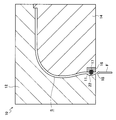
- FIG. 6 is a plan sectional view of the mold used in the first embodiment at a position where a jig that contacts the inside of the coated bead is provided. It is a metal mold
- 1st Embodiment it is a perspective view which shows that the coating resin of adjacent coating
- 1st Embodiment it is a perspective view which shows the modification of heat-welding coating resin of adjacent coating
- FIG. 7B is a perspective view for explaining that the thermoplastic material is injected radially into the cavity in the second embodiment, and is a partially enlarged view in which the bead core in FIG. 7A is not drawn.
- FIG. 6 is a cross-sectional plan view of a tire molding die used in the second embodiment at a position where a bead core forming die portion is arranged instead of a jig.
- it is a perspective view explaining covering the part which the bead core was exposed with a thermoplastic material.
- thermoplastic molten material means a molten material of the thermoplastic material
- thermoplastic material means a solidified material.
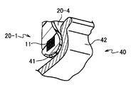
- a pneumatic tire T manufactured by the tire manufacturing method of the present invention includes a pair of bead portions 20-1 and side portions 20- extending outward from the bead portions 20-1 in the tire radial direction. 2 and a crown portion 20-3 that connects a tire radial outer end of one side portion 20-2 and a tire radial outer end of the other side portion 20-2.
- the tire frame member 20 is made of a thermoplastic material.
- a mold (tire molding mold) 10 as shown in FIG. 1A is used.
- a tire half 20 ⁇ / b> H is formed by dividing the tire frame member 20 constituting the bead portion 20-1 to the tire center CL into two along the tire center CL shown in FIG. 3A.
- the mold 10 includes an outer mold 12 that molds the tire outer surface side and an inner mold 14 that molds the tire inner surface side.
- the inner die 14 is provided with a main jig 16 for fixing the coated beads.
- a cavity S (space) in the shape of a tire frame member is formed between the outer mold 12 and the inner mold 14.
- the outer mold 12 is provided with an auxiliary jig 22 for fixing the coated beads.
- a plurality of main jigs 16 are arranged at equal intervals along the housing position of the covering beads 11.
- twelve main jigs 16 are arranged at equal intervals along the accommodation position of the covering beads 11.
- the main jig 16 is formed with a concave portion 17 corresponding to the outer shape of the coated bead 11 described later.
- the covering bead 11 is in a state where movement in the tire inner direction is restricted and movement in the vertical direction (tire radial direction) is also restricted.
- the auxiliary jig 22 supports the coated bead 11 from the outside of the tire.
- the auxiliary jig 22 is provided at a position corresponding to the main jig 16 to support the covering bead 11 so as to be sandwiched between the main jig 16.
- the auxiliary jig 22 may be provided in a portion not corresponding to the main jig 16 to support the coated bead 11.
- thermoplastic molten material passes through the outer side of the tire of the coated bead 11 with the coated bead 11 entering the recess 17.
- This molten material is, for example, in a molten state of a thermoplastic elastomer (TPE) or a thermoplastic resin.
- the gate 18 is a disk gate opened in a ring shape, and the cavity S is formed so as to communicate with the ring-shaped gate 18 and spread in a hollow disk shape.
- the gate 18 may be a pin gate, but from the viewpoint of formability, the disk gate is more preferable in this way.
- the coated bead 11 is arranged at a predetermined position in the mold 10 and a thermoplastic molten material (often a molten thermoplastic polymer material) is injected, and the tire half on one side is injected.
- the tire half body 20H (see FIG. 3A) constituting the tire is molded. And as shown to FIG. 3A, the tire half part 20H of one side and the tire half part 20H of the other side are joined by the tire center CL, and the tire frame member 20 for the whole tire is formed.
- the steel cord K is wound in a spiral manner in the tire circumferential direction to increase the circumferential rigidity. Further, the steel cord K may be embedded in the tire frame member 20.
- the chafer 20-4 is affixed to the portion that fits into the wheel (rim flange) to improve the fit to the rim.
- a rubber material (tread rubber G2) is attached to a portion in contact with the road surface to improve wear resistance and breakage resistance.
- thermoplastic material thermoplastic resin
- a thermoplastic material thermoplastic resin
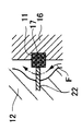
- a large number of coated steel cords 13 formed by coating a steel cord 13S with a thermoplastic resin as shown in FIG.
- the outer peripheral side of the steel cord 13S is entirely covered with a coating resin 13R.
- the steel cord 13S is made of, for example, a metal monofilament or a metal stranded wire.
- thermoplastic molten material is coated on the outer peripheral side of the steel cord, and the molten material is solidified by cooling to become a thermoplastic material. Code.
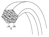
- the outer shape of the resin as it comes out of the extruder can be round or triangular (see, for example, a coated steel cord 19 in which a steel cord 19S is coated with a coating resin 19R as shown in FIG. 4) or a square (rectangle or rhombus). Etc.) or a chamfered shape, and is not particularly limited.
- an adhesion treatment for adhering the metal and the coating resin 13R in advance before coating.
- a silane coupling agent is applied extremely thinly.
- a degreasing treatment prior to the adhesion treatment is more preferable from the viewpoint of adhesion.
- the manufactured coated steel cord 13 is wound around a winding jig at least once, and the coated resin portions 13RP of the coated steel cord portions adjacent to each other are thermally welded to each other to coat the coated beads 11 (For example, a strand bead coated with a resin or a monostrand bead) is formed.
- the winding side of the winding jig has the same dimensions as the inner periphery of the coated bead 11.
- the number of windings is preferably 2 or more from the viewpoint of stabilizing the strength.
- the coating resin portion 13RP may be melted with hot air and re-solidified, or the tip having a high temperature is brought into contact with the coating resin portion 13RP to be melted and re-solidified. May be welded. Further, the iron may be brought into contact with the hot air.
- the coating resin 13R is preferably the same type as a thermoplastic resin constituting the tire frame member 20 described later, but may be a different resin as long as it is a resin that adheres to the thermoplastic resin.
- the Young's modulus of the coating resin 13R is preferably in the range of 0.05 to 10 times that of the thermoplastic resin constituting the tire frame member 20. If it is 11 times or more, it is considered that the rigidity of the coated bead 11 becomes too high and it is difficult to assemble the rim.
- the rigidity of the coated bead 11 becomes too low, and it is considered that the coated bead 11 is easily separated without being able to withstand the pressure of the molten resin at the time of injection molding.
- the mold 10 is opened, the tire inner side portion of the coated bead 11 manufactured in this way is put in the concave portion 17 of the main jig 16, the coated bead 11 is held by the main jig 16, and the mold 10 is closed,
- the auxiliary jig 22 supports the outside of the tire of the coated bead 11.
- thermoplastic molten resin F is injected from the gate 18 into the mold 10 and injection molded to form the tire half 20H.
- the molten resin F is injected from the gate 18 so as to pass between the covering bead 11 and the outer mold 12, so that the covering bead 11 is a tire. It is pressed from the outside toward the inside of the tire. Therefore, the moving force received by the coated bead 11 can be sufficiently supported by the main jig 16.
- the coating resin portions adjacent to each other of the coated steel cord 13 are thermally welded. Therefore, the resin is sufficiently formed between the cords in the coated bead 11. Therefore, in the tire half 20H formed by placing the coated bead 11 on the mold 10, and the tire frame member 20 and the pneumatic tire T using the tire half 20H, a resin is provided between the cords of the coated bead 11. Is sufficiently formed.
- each steel cord 13S of the bead portion 20-1 is covered with a coating resin 13R over the entire circumference. Therefore, since the portion where the steel cord 13S is exposed is not formed, the steel cord 13S is reliably prevented from being rusted.
- thermoplastic molten material is injected into the cavity S in a state in which the covering bead 11 is in contact with the main jig 16 from the direction inside the tire.
- the auxiliary jig 22 for preventing the displacement of the coated bead 11 is brought into contact with the coated bead 11 in a slight region from the outside of the tire, and the thermoplastic molten material is injected. Therefore, on the outer side of the formed tire half 20H, the portion where the injection molded thermoplastic material (thermoplastic resin) is not formed because the auxiliary jig 22 is in contact is a slight area even if formed. It is. Therefore, the air retainability when assembling the rim is ensured.
- the rim 40 is arranged on the tire inner side (the space side into which air enters) than the close contact portion with the bead seat portion 41 and the rim flange 42. Therefore, there is no influence on the air retention when assembling the rim. Therefore, it is possible to obtain a jig size and shape that sufficiently ensure the prevention of breakage of the thermoplastic material around the coated bead 11 when the pot is pulled out, and sufficiently suppress the displacement of the coated bead 11 when the tire is molded. Can do.
- the auxiliary jig 22 may have a mold structure capable of moving forward and backward into the cavity, and the molten resin may be continuously injected while the auxiliary jig 22 is retracted.
- the molten resin can be injected before the already injected molten resin is too solidified. Therefore, the molten resin can flow into the portion where the auxiliary jig 22 is in contact, and a thermoplastic material can be formed.
- the main jig 16 can be similarly moved forward and backward, so that the molten resin can flow into the portion where the main jig 16 is in contact to form a thermoplastic material.
- the timing for retracting the auxiliary jig 22 and the main jig 16 from the coated bead 11 is determined in advance based on the dimensions of the cavity S and the temperature of the thermoplastic molten resin injected into the cavity S. Therefore, it is not necessary to detect the solidified state of the injected molten resin.
- the molten resin can be removed without using the auxiliary jig 22. It may be injected. Moreover, it is also possible to make the main jig 16 contact from the tire outer side instead of the tire inner side.
- the molten resin when the molten resin is injected, it is injected from between the coated bead 11 and the outer mold 12 that forms the outer side of the tire. For this reason, the covering bead 11 is pressed from the tire outer side toward the tire inner side at the time of injection. Therefore, the moving force received by the coated bead 11 can be sufficiently supported by the main jig 16. Further, when the molten resin is injected, such an effect can be obtained even if it is injected at a high pressure for injection molding.
- jigs 16 are arranged at a plurality of positions along the circumferential direction of the cavity S. Thereby, the position accuracy of the covering bead 11 can be further improved.
- a skeleton portion from the bead portion B to the tire center CL is formed. That is, a half part of the tire frame member 20 is formed. Accordingly, by joining the two tire halves 20H at the tire center CL, the tire skeleton member 20 with a coated bead for the entire tire can be formed. This joining is performed by a welding method using a molten resin or a hot plate welding method.
- the joining member 21 joined at the tire center CL may be formed of the same type of resin as the tire skeleton member 20 or may be formed of a different type of resin from the tire skeleton member 20.
- the tire half part 20H which forms the half part of the tire frame member 20 forms a tubular tire frame member, You may make it the structure which can be filled with air in a tire frame member.
- the pair of bead portions 12, the pair of side portions 14, and the crown portion 16 may be integrally formed.
- thermoplastic molten resin is injected into the cavity as the thermoplastic molten material, but a molten thermoplastic elastomer (TPE) may be injected.
- thermoplastic elastomer examples include amide-based thermoplastic elastomer (TPA), ester-based thermoplastic elastomer (TPC), olefin-based thermoplastic elastomer (TPO), styrene-based thermoplastic elastomer (TPS) specified in JIS K6418, Examples thereof include urethane-based thermoplastic elastomer (TPU), crosslinked thermoplastic rubber (TPV), and other thermoplastic elastomers (TPZ).
- thermoplastic synthetic resin examples include urethane resin, olefin resin, vinyl chloride resin, polyamide resin, and the like.
- thermoplastic materials for example, the deflection temperature under load (0.45 MPa load) specified in ISO 75-2 or ASTM D648 is 75 ° C. or more, the tensile yield strength specified in JIS K7113 is 10 MPa or more, Similarly, the tensile yield point elongation specified in JIS K7113 is 10% or more, the tensile fracture elongation specified in JIS K7113 is 50% or more, and the Vicat softening temperature (Method A) specified in JIS K7206 is 130 ° C or more. Things can be used.
- the basic structure of the pneumatic tire T manufactured in the present embodiment which will be described for the second embodiment of the present invention, is the same as that in the first embodiment (see FIG. 3).
- the same parts as those in the first embodiment are denoted by the same reference numerals, and detailed description thereof is omitted.
- the covering bead 11 of this embodiment the thing similar to what was demonstrated in 1st Embodiment can be used, However, For the sake of simplification, it is illustrated with a circular cross section.
- the mold 50 used in the tire manufacturing method of the present embodiment is for molding the tire half 20H, as in the first embodiment. As shown in FIG. 5A, the outer mold for molding the tire outer surface side.
- the inner die 54 is provided with a main jig 56 for fixing the coated beads.
- the main jig 56 is configured such that the position of the advancing / retreating direction in the cavity S is variable, and can be replaced with a bead portion forming mold portion 55 described later.
- a moving space 59 is formed in the inner die 54 on the side of the main jig 56 in the backward direction so that this replacement can be performed.
- the main jig 56 is formed with a concave portion 56A corresponding to the outer shape of the coated bead 11, and when the coated bead 11 is placed in the mold 50, a part of the coated bead 11 enters and holds the concave portion 56A. It will be in the state. As a result, the covering bead 11 is in a state where movement in the tire inner direction is restricted and movement in the vertical direction (tire radial direction) is also restricted.
- the main jig 56 is provided so as to be movable back and forth at the set position. As shown in FIG. 5B, at the position where the main jig 56 has advanced (the position protruding into the cavity S), a part of the coated bead 11 is formed. This is the position where the recess 56A enters, that is, the position where the bead core 11 can be supported from the inside of the tire.
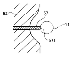
- the mold 50 is provided with an auxiliary jig 57 whose position in the advancing and retreating direction in the cavity S can be changed in order to further prevent displacement of the coated bead 11, and this auxiliary jig 57 is attached to the coated bead 11. It is possible to inject the thermoplastic molten resin F radially into the cavity in a state where it is in contact with a small area from the outside of the tire.
- the auxiliary jig 52 is provided at a position corresponding to the main jig 56 and supports the covering bead 11 so as to be sandwiched between the main jig 56.
- the auxiliary jig 57 may be provided in a portion not corresponding to the main jig 56 to support the coated bead 11.
- the front end surface (contact surface to the coated bead 11) 57T of the auxiliary jig 57 is flush with the surrounding cavity inner wall at the position where the auxiliary jig 57 is retracted, and the bead portion 20-1 is intended. It becomes the molding surface which is molded into the shape.
- a moving space 53 is formed on the outer die 52 on the side of the auxiliary jig 57 in the retracting direction so that the retraction is possible (see FIGS. 5A and 5B).
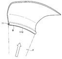
- the mold 50 is provided with a bead portion forming mold portion 55 that is arranged in place of the main jig 56 when the main jig 56 is retracted.
- the bead portion forming mold portion 55 has a curved concave inner wall surface 55 ⁇ / b> A along the outer shape of the coated bead 11.
- the bead portion 20-1 of the tire half 20H (see FIG. 3) is injected by injecting the thermoplastic molten resin F in a state where the bead portion forming mold portion 55 is disposed in place of the main jig 56. Can be formed into the intended shape.
- thermoplastic polymer material is, for example, a thermoplastic elastomer (TPE) or a thermoplastic resin.
- the gate 58 is a disk gate opened in a ring shape, and the cavity S is formed so as to communicate with the ring gate 58 and spread in a hollow disk shape.
- the gate 58 may be a pin gate, but a disk gate is preferable in this way from the viewpoint of formability.
- the coated bead 11 is disposed at a predetermined position in the mold 50, and a thermoplastic polymer material such as a thermoplastic resin is injected to form the tire half 20H constituting the half on one side of the tire. Mold.
- a thermoplastic polymer material such as a thermoplastic resin
- the tire half 20H on one side and the tire half 20H on the other side are joined at the tire center CL to form the tire frame member 20 for the entire tire.
- the reinforcement of the crown portion 20-3 with the steel cord K, the formation of the chafer 20-4, and the formation of the tread by attaching the tread rubber G2 can be performed in the same manner as in the first embodiment.
- the mold 50 is opened, the inner part of the tire of the coated bead 11 is inserted into the concave portion 56 ⁇ / b> A of the main jig 56, the coated bead 11 is held by the main jig 56, the mold 50 is closed, and the auxiliary jig 55 closes the coated bead 11. Supports the outside of the tire.
- the resin coated on the cord is the same material as the thermoplastic resin forming the tire frame member 20. It may be a different material. Even if the Young's modulus of the resin covering the cord is in the range of 0.1 to 2 times that of the thermoplastic resin forming the tire frame member 20, there is no problem in rim assembly.
- thermoplastic molten resin F is injected from the gate 58 into the cavity S in the mold 50 and injection molded to form the tire half 20H.
- the molten resin F is injected from the gate 58 through the cavity portion between the covering bead 11 and the outer mold 52 in the covering bead 11 portion where the main jig 56 is in contact.
- the covering bead 11 is pressed from the tire outer side toward the tire inner side. Therefore, the moving force received by the coated bead 11 can be sufficiently supported by the main jig 56.
- the coated bead 11 can be supported, and then the auxiliary jig 57 is first retracted from the coated bead 11.
- the timing for retracting the auxiliary jig 57 from the coated bead 11 is determined in advance based on the dimensions of the cavity S, the temperature of the thermoplastic molten resin F injected into the cavity S, and the injection flow rate of the molten resin F. Keep it.
- the coated bead 11 can be held by the semi-solidified resin and the main jig 56, and the molten thermoplastic resin F is injected, so that the auxiliary jig 57 is injected. This is the timing at which the coated bead portion 11P exposed by the retreating can be covered with resin.
- the back of the auxiliary jig 57 exposes the covered bead portion 11P, which the auxiliary jig 57 has been in contact with, in the cavity S (see FIGS. 6A and 6B).
- the thermoplastic molten resin F is continuously injected into the cavity S while being retracted.
- the already injected semi-solidified resin located around the auxiliary jig 57 is pressed and deformed by the injected molten resin, and the space V (see FIG. 6B) in which the auxiliary jig 57 is retracted is sequentially filled.
- the coated bead portion 11P is covered with the molten resin, and the outer side of the tire of the bead portion 20-1 is formed into an intended shape.
- the main jig 56 is retracted from the covering bead 11.
- the timing for retracting the main jig 56 from the coated bead 11 is the same as in the case of the auxiliary jig 57, the dimensions of the cavity S, the temperature of the thermoplastic molten resin injected into the cavity S, and the molten resin.
- the injection flow rate is determined in advance. This timing is a timing at which the coated bead 11 can be supported by the solidified resin even when the main jig 56 is separated from the coated bead 11.
- the coated bead 11Q with which the main jig 56 is in contact is exposed in the cavity S (see FIG. 7A).
- the bead portion forming mold portion 55 is moved in the mold 50 to reach a predetermined position of the inner mold 54.
- the predetermined position is a position where the cavity inner wall surface 55A of the bead portion forming mold portion 55 can be molded into the intended shape with the surrounding mold inner wall surface.
- the exposed coated bead portion 11Q is covered with the molten resin to form a thermoplastic material (solidified resin) (see FIG. 9). Accordingly, the coated bead portion 11Q is covered with a resin, and the inside of the tire of the bead portion 20-1 is formed into an intended shape.
- the bead 20-1 is covered with resin over the entire circumference. Therefore, in the pneumatic tire using the tire half portion 20H, the air retainability when assembling the rim is sufficiently ensured. Moreover, the bead portion 20-1 can bear the tension over the entire circumference, and the strength of the bead portion 20-1 can be increased.
- the molten resin is continuously injected while the auxiliary jig 57 is moved backward. Therefore, compared with the case where the molten resin is injected after the auxiliary jig 57 is retracted, the molten resin can be injected before the already injected molten resin is excessively solidified. Therefore, it is easy to press and deform the surrounding semi-solidified resin into the gap formed by the retreat of the auxiliary jig 57 and fill it.
- the timing for retracting the auxiliary jig 57 and the main jig 56 from the coated bead 11 is based on the size of the cavity S and the temperature of the thermoplastic molten resin injected into the cavity S, respectively. It is determined in advance. Therefore, it is not necessary to detect the solidified state of the injected molten resin. Further, when the thermoplastic molten resin is injected, such an effect can be obtained even if it is injected at a high pressure for injection molding.
- the auxiliary jig 57 and the main jig 56 are arranged at a plurality of positions along the housing position of the covering bead 11. Thereby, the position accuracy of the covering bead 11 can be further improved.
- the main jig 56 may be formed of a magnet material (magnet), and the coated bead 11 may be formed of a magnetic material so as to be attracted by a magnetic force. This makes it easy to hold the coated bead 11 with the main jig 56, and when the auxiliary jig 57 is retracted, the auxiliary jig 57 can be easily held even if the resin holding the coated bead 11 is semi-solidified and the holding force is weak. Can be moved. In this case, you may use the main jig covered with the shielding member which does not escape magnetic force except the direction of the covering bead 11. FIG.
- the molten resin F when the molten resin F is injected, the molten resin F is injected through the cavity portion between the coated bead 11 and the outer mold 52 in the coated bead 11 portion where the main jig 56 is in contact. The For this reason, since the covering bead 11 is pressed from the tire outer side toward the tire inner side at the time of injection, the moving force received by the covering bead 11 can be sufficiently supported by the main jig 56.
- the tire frame member 20 with the bead core for the whole tire can be formed by joining the two tire frame members at the tire center CL.
- the joining member 21 joined at the tire center CL may be formed of the same type of resin as the tire skeleton member 20 or may be formed of a different type of resin from the tire skeleton member 20.
- a tube-shaped tire frame member may be formed in place of the tire frame member 20, and the tire frame member may be filled with air. Moreover, you may form the tire frame member 20 integrally.
- the backward movement time is sequentially shifted, and the bead unit 20-1 is further moved by moving backward so as to cause a so-called time delay. It is also possible to have an intended shape.
- the timing of separating the auxiliary jig 57 and the main jig 56 from the coated bead 11 is determined based on the dimensions of the cavity S, the temperature of the thermoplastic molten resin injected into the cavity S, and the injection flow rate of the molten resin.
- the auxiliary jig 57 is arranged on the basis of the temperature measured by the sensor by arranging a sensor (for example, a temperature sensor for measuring the resin temperature) in the mold 50.
- the timing for separating the main jig 56 from the covering bead 11 may be set.
- the molten resin can be removed without using the auxiliary jig 57. It may be injected.
- the main jig 56 is replaced with the bead portion forming mold portion 55 and the resin is formed on the exposed coated bead portion 11Q.
- the main jig 56 is retracted from the coated bead 11. It is also possible to cover the bead core portion 11Q with the resin by injecting the thermoplastic molten resin F.
- thermoplastic molten resin is injected into the cavity as the thermoplastic material.
- a thermoplastic elastomer TPE
- thermoplastic elastomer the thing similar to 1st Embodiment can be used.
- thermoplastic material used as the resin material
- a tire may be manufactured using a thermosetting resin such as a urea resin or a phenolic resin
- the resin material used in the present invention is a thermoplastic material. Is not limited. Needless to say, the scope of rights of the present invention is not limited to the above embodiment.
Landscapes
- Engineering & Computer Science (AREA)
- Mechanical Engineering (AREA)
- Manufacturing & Machinery (AREA)
- Tires In General (AREA)
- Tyre Moulding (AREA)
Abstract
コードを樹脂材料で被覆してなる被覆コードを形成し、被覆コードの樹脂材料同士を溶着又は接着させつつビード状に形付けていくことにより、コード間が樹脂材料で埋められた被覆ビードを形成し、タイヤ骨格部材を成形する金型のキャビティ内に配置されたジグに被覆ビードを当接させて金型内に被覆ビードを固定し、溶融した樹脂材料をキャビティ内に注入することにより、タイヤビード部に前記被覆ビードを有するタイヤ骨格部材を成形する。
Description
本発明は、樹脂材料を金型内に注入してタイヤ骨格部材を成形するタイヤの製造方法、タイヤ、及び、タイヤ成形用金型に関する。
従来から、ゴム、有機繊維材料、及びスチール部材で形成されているタイヤが知られている。近年、軽量化やリサイクルのし易さの観点から、樹脂材料をタイヤに用いることが求められている。ここで記載する樹脂材料とは、熱可塑性樹脂や熱硬化性樹脂を含む概念であり、熱や電子線によって架橋が生じる樹脂や、熱転位によって硬化する樹脂も含む概念である。
このような樹脂を用いた例として、例えば特開平05-116504号公報には、熱可塑性エラストマー(TPE)でビードコアを覆ってタイヤ骨格部材を形成することが提案されている。
特開平05-116504号公報
このような樹脂を用いた例として、例えば特開平05-116504号公報には、熱可塑性エラストマー(TPE)でビードコアを覆ってタイヤ骨格部材を形成することが提案されている。
ところで、このようなタイヤ骨格部材では、ビードコアとして従来のゴムタイヤで用いられているゴム被覆のストランドビードコアを用いると、接着や加硫の観点で好ましくないので、ビードコアとしてはケーブルビードコアを用いることが多い。しかし、ケーブルビードコアでは、コストが嵩むことに加え、樹脂材料でタイヤ骨格部材を形成した際にコード間に樹脂材料を充分に入り込ませることが難しい。
本発明は、上記事実を考慮して、コード間に樹脂材料を充分に形成することができるタイヤの製造方法、このタイヤ製造方法を用いて製造したタイヤ、及び、タイヤ成形金型を提供することを課題とする。
本発明は、上記事実を考慮して、コード間に樹脂材料を充分に形成することができるタイヤの製造方法、このタイヤ製造方法を用いて製造したタイヤ、及び、タイヤ成形金型を提供することを課題とする。
本発明の第1の態様のタイヤの製造方法は、コードを樹脂材料で被覆してなる被覆コードを形成し、前記被覆コードの樹脂材料同士を溶着又は接着させつつビード状に形付けていくことにより、コード間が樹脂材料で埋められた被覆ビードを形成し、タイヤ骨格部材を成形する金型のキャビティ内に配置されたジグに前記被覆ビードを当接させて前記金型内に前記被覆ビードを固定し、溶融した樹脂材料を前記キャビティ内に注入することにより、タイヤビード部に前記被覆ビードを有するタイヤ骨格部材を成形する。
本明細書で樹脂材料とはゴムも含む概念である。また、タイヤ骨格部材は、通常、円環状(トロイダル状)である。
本発明の第1の態様のタイヤの製造方法では、被覆コードを形成する際、樹脂材料とコードとが接着するように形成する。例えば、熱可塑性の溶融樹脂材料をコードの外周側に被覆し、冷却により溶融材料が固化して熱可塑性材となることで被覆コードとする。
更に、複数本の被覆コードの樹脂材料同士を溶着又は接着させて形付けていくことで被覆ビードを形成する。従って、被覆ビードでは、コードに接着した樹脂材料がコード間に予め形成されている。
なお、被覆ビードを形成する際、1本の被覆コードを螺旋状に巻いて形成してもよいし、複数本の被覆コードを用いて形成してもよい。
本発明の第1の態様のタイヤの製造方法では、被覆コードを形成する際、樹脂材料とコードとが接着するように形成する。例えば、熱可塑性の溶融樹脂材料をコードの外周側に被覆し、冷却により溶融材料が固化して熱可塑性材となることで被覆コードとする。
更に、複数本の被覆コードの樹脂材料同士を溶着又は接着させて形付けていくことで被覆ビードを形成する。従って、被覆ビードでは、コードに接着した樹脂材料がコード間に予め形成されている。
なお、被覆ビードを形成する際、1本の被覆コードを螺旋状に巻いて形成してもよいし、複数本の被覆コードを用いて形成してもよい。
このようにして形成された被覆ビードを金型内に固定する。その際、金型のキャビティ内にジグを配置して被覆ビードを当接させて固定する。そして、金型を閉じ、溶融した樹脂材料をキャビティ内に注入することによりタイヤ骨格部材を成形する。
従って、このようにして形成されたタイヤ骨格部材では、コード間に樹脂材料が充分に形成されている。
従って、このようにして形成されたタイヤ骨格部材では、コード間に樹脂材料が充分に形成されている。
なお、溶融した樹脂材料(熱可塑性材料や熱硬化性材料など)の注入は射出成形をするための高圧の注入であってもよい。また、タイヤ骨格部材をチューブ状に形成して、タイヤ骨格部材内に空気を充填できる構造にしてもよい。
また、溶融した樹脂材料として熱可塑性材で溶融状態のもの(熱可塑性の溶融材料)を用いる場合には、ゴム様の弾性を有する熱可塑性エラストマー(TPE)、熱可塑性樹脂等を用いることができるが、走行時の弾性と製造時の成形性とを考慮すると熱可塑性エラストマーを注入することが好ましい。
また、溶融した樹脂材料として熱可塑性材で溶融状態のもの(熱可塑性の溶融材料)を用いる場合には、ゴム様の弾性を有する熱可塑性エラストマー(TPE)、熱可塑性樹脂等を用いることができるが、走行時の弾性と製造時の成形性とを考慮すると熱可塑性エラストマーを注入することが好ましい。
本発明の第2の態様のタイヤの製造方法は、樹脂材料として熱可塑性材料を用いる。これにより、溶融した熱可塑性材料をキャビティ内に注入し、キャビティ内壁から熱を奪うことにより熱可塑性材料を固化させることができるので、タイヤの製造が容易である。また、再利用が容易であることから、資源の有効利用が可能である。
本発明の第3の態様のタイヤの製造方法は、前記被覆コードを形成する際に、前記コードを複数本束ねるとともにコード間が樹脂材料で埋められるように樹脂材料で被覆する。
これにより、1本あたりの被覆コードが複数本のコードを有する場合であっても、コード間に隙間が形成されることが回避される。
これにより、1本あたりの被覆コードが複数本のコードを有する場合であっても、コード間に隙間が形成されることが回避される。
本発明の第4の態様のタイヤの製造方法は、前記コードとしてスチールコードを用いる。これにより、コードの強度、耐熱性を大幅に高めることができる。
本発明の第5の態様のタイヤの製造方法は、前記ジグに前記被覆ビードを当接させる際に、タイヤ内側となる方向から当接させる。
本発明の第5の態様のタイヤの製造方法では、タイヤ骨格部材のタイヤ内側に、ジグが当接していたことにより、金型内に注入してなる樹脂材料が形成されない部分が生じるが、この部位が大きくてもリム組み時のエア保持性に影響がない。従って、釜抜き時における被覆ビード周辺の熱可塑性材の破壊防止性を充分に確保したジグ寸法、形状とすることができる。
本発明の第5の態様のタイヤの製造方法では、タイヤ骨格部材のタイヤ内側に、ジグが当接していたことにより、金型内に注入してなる樹脂材料が形成されない部分が生じるが、この部位が大きくてもリム組み時のエア保持性に影響がない。従って、釜抜き時における被覆ビード周辺の熱可塑性材の破壊防止性を充分に確保したジグ寸法、形状とすることができる。
本発明の第6の態様のタイヤの製造方法は、溶融した樹脂材料を前記タイヤビード部側から注入する。
本発明の第6の態様のタイヤの製造方法では、溶融した樹脂材料を注入すると、ジグが設けられた位置では、この溶融した樹脂材料が被覆ビードのタイヤ外面側を通過する。このため、被覆ビードがタイヤ外側からタイヤ内側に向けて押圧される。従って、注入時に被覆ビードが受ける移動力をジグで充分に支えることができる。
本発明の第6の態様のタイヤの製造方法では、溶融した樹脂材料を注入すると、ジグが設けられた位置では、この溶融した樹脂材料が被覆ビードのタイヤ外面側を通過する。このため、被覆ビードがタイヤ外側からタイヤ内側に向けて押圧される。従って、注入時に被覆ビードが受ける移動力をジグで充分に支えることができる。
本発明の第7の態様のタイヤの製造方法は、前記キャビティの周方向に沿って前記ジグを複数配置する。
これにより、被覆ビードの位置精度をより向上させることができる。
これにより、被覆ビードの位置精度をより向上させることができる。
本発明の第8の態様のタイヤの製造方法は、前記タイヤ骨格部材として、前記タイヤビード部からタイヤセンターまでの骨格部分を形成する。
本発明の第8の態様のタイヤの製造方法では、タイヤ半部を構成するタイヤ骨格部材を形成することになる。従って、2つのタイヤ骨格部材をタイヤセンターで接合することにより、タイヤ全体用の被覆ビード付きの骨格部材を形成することができる。
本発明の第8の態様のタイヤの製造方法では、タイヤ半部を構成するタイヤ骨格部材を形成することになる。従って、2つのタイヤ骨格部材をタイヤセンターで接合することにより、タイヤ全体用の被覆ビード付きの骨格部材を形成することができる。
本発明の第9の態様のタイヤの製造方法は、前記キャビティ内の樹脂材料で前記被覆ビードを保持可能となった後、前記ジグを前記ビードコアから後退させて前記ジグが当接していた被覆ビード部分を露出させるとともに、溶融した樹脂材料を前記キャビティ内に注入することで露出した該被覆ビード部分を樹脂材料で覆うものである。
本発明の第9の態様のタイヤの製造方法では、被覆ビードをジグに当接させてキャビティ内に固定した状態で、溶融した樹脂材料をキャビティ内に注入する。
そして、注入した樹脂材料が完全ではなくともある程度に固化することでジグがなくてもビードコアを保持可能な状態になった後、ジグをビードコアから後退させて被覆ビードに非当接とする。この結果、ジグが当接していた被覆ビード部分がキャビティ内に露出する。また、溶融した樹脂材料をキャビティ内に注入して、この露出した被覆ビード部分を樹脂材料で覆う。
これにより、被覆ビードが露出している部分が形成されないタイヤ骨格部材が形成される。従って、リム組み時のエア保持性が充分に確保され易く、しかも、タイヤ成形時での被覆ビードの位置ずれを抑制しつつビード部の強度を高めたタイヤを製造することができる。
なお、ジグを被覆ビードに非当接とした後、ビード部を意図した形状にする金型部分をジグに代えて配置することが好ましい。この場合、金型内でそのような金型部分がジグと入れ替えで配置される構造にしてもよいし、ジグが複数部材で構成され、ジグの一部がそのような金型部分を構成する構造にしてもよい。
このような金型を配置することでビード部が意図した形状に成形されるので、ビード部の強度を充分に上げることができる。
このような金型を配置することでビード部が意図した形状に成形されるので、ビード部の強度を充分に上げることができる。
溶融した樹脂材料(熱可塑性材料や熱硬化性材料など)の注入は射出成形をするための高圧の注入であってもよい。また、タイヤ骨格部材をチューブ状に形成して、タイヤ骨格部材内に空気を充填できる構造にしてもよい。
樹脂材料としては、ゴム様の弾性を有する熱可塑性樹脂、熱可塑性エラストマー(TPE)や熱硬化性樹脂等を用いることができるが、走行時の弾性と製造時の成形性とを考慮すると熱可塑性エラストマーを注入することが好ましい。
本発明の第10の態様のタイヤの製造方法は、樹脂材料で前記被覆ビードを保持可能となった後、前記ジグを前記被覆ビードから後退させながら樹脂材料を前記キャビティ内に注入する。
これにより、ジグを後退させた後に樹脂材料を注入する場合に比べ、既に注入した樹脂材料が固化し過ぎる前に樹脂材料を注入することができる。従って、ジグの後退により形成される隙間に、周囲の樹脂材料を押圧変形させて入れ込み易い。
本発明の第11の態様のタイヤの製造方法は、前記ジグを前記被覆ビードから後退させるタイミングを、前記キャビティの寸法と、前記キャビティ内に注入する樹脂材料の温度と、樹脂材料の注入流量と、に基づいて決定する。
これにより、注入した樹脂材料の固化状態などを検出しなくても、請求項1に記載の発明の効果を奏することができる。
本発明の第12の態様のタイヤの製造方法は、前記被覆ビードを磁性体で形成し、前記ジグに磁気を帯びさせる。
ジグに磁気を帯びさせるには、ジグを磁石で形成してもよいし、ジグ外部から磁石等で磁力線をジグに及ぼしてもよい。
本発明の第12の態様のタイヤの製造方法により、被覆ビードをジグで保持し易くなる。また、ジグを後退させる際にも容易に移動させることができる。
本発明の第13の態様のイヤ成形用金型は、融した樹脂材料を注入することでタイヤ骨格部材を成形するキャビティと、キャビティ内で進退動する被覆ビード保持用のジグと、を備えている。
本発明の第13の態様のタイヤ成形用金は、タイヤ骨格部材を成形するキャビティを有し、キャビティ内にジグを進出させ、ジグで被覆ビードを保持した状態で樹脂材料を注入する。そして、注入した溶融樹脂がある程度に固化することでジグがなくても被覆ビードを保持可能な状態となった後、ジグを被覆ビードから後退させて被覆ビードに非当接とする。この結果、ジグが当接していた被覆ビード部分がキャビティ内に露出する。この状態でさらに、溶融した樹脂材料をキャビティ内に注入して、この露出した被覆ビード部分を樹脂材料で覆う。
これにより、被覆ビードが露出している部分が形成されないタイヤ骨格部材が形成される。従って、リム組み時のエア保持性を充分に確保し、しかも、タイヤ成形時での被覆ビードの位置ずれを抑制しつつビード部の強度を高めたタイヤを製造するタイヤ成形用金型が実現される。
ここで、ジグを被覆ビードに非当接とした後、ビード部を意図した形状にする金型部分がジグに代えて配置される構造にしておくことが好ましい。この場合、金型内でそのような金型部分がジグと入れ替えて配置される構造にしてもよいし、ジグが複数部材で構成され、ジグの一部がそのような金型部分を構成する構造にしてもよい。
これにより、ビード部の強度を充分に上げることができる。
本発明の第14の態様のタイヤは、コードが樹脂材料で被覆された被覆コードが巻回されてビード状に形付けされ、隣接する前記被覆コードの樹脂材料同士が溶着又は接着して、隣接するコード間が樹脂材料で埋められた被覆ビードと、タイヤビード部、タイヤサイド部、及び、タイヤクラウン部を有し、前記被覆ビードが前記タイヤビード部に埋設された、タイヤ骨格部材と、を備えている。
本発明の第14の態様のタイヤでは、被覆ビードは、コードが樹脂材料で被覆された被覆コードが巻回されてビード状に形付けされ、隣接する被覆コードの樹脂材料同士が溶着又は接着して、隣接するコード間が樹脂材料で埋められている。そして、タイヤビード部、タイヤサイド部、及び、タイヤクラウン部を有するタイヤ骨格部材のビード部に被覆コードが埋設されている。したがって、このタイヤ骨格部材を用いてコード間に樹脂材料が充分に形成されたタイヤを得ることができる。
本発明によれば、コード間に樹脂材料を充分に形成することができるタイヤの製造方法、タイヤ、及び、タイヤ成形金型とすることができる。
[第1実施形態]
以下、樹脂材料として熱可塑性材料を用いる実施形態を挙げ、本発明の実施の形態について説明する。なお、本実施形態では、熱可塑性の溶融材料とは熱可塑性材の溶融状態のものをいい、熱可塑性材とは固化状態のものをいう。
本発明のタイヤ製造方法で製造される空気入りタイヤTは、図3Aに示されるように、1対のビード部20-1と、ビード部20-1からタイヤ径方向外側に延びるサイド部20-2と、一方のサイド部20-2のタイヤ径方向外側端と他方のサイド部20-2のタイヤ径方向外側端とを連結するクラウン部20-3と、を有するタイヤ骨格部材(タイヤケース)20と、ビード部20-1の表面側に形成されたチェーファー20-4と、を備えている。ビード部20-1は、図3Bに示されるように、リム組みされた状態で、リム40のビードシート部41、及びリムフランジ42に密着するよう構成されている。タイヤ骨格部材20は熱可塑性材料で形成されている。
本実施形態では、図1Aに示すような金型(タイヤ成形用金型)10を用いる。この金型10では、図3Aに示す、ビード部20-1からタイヤセンターCLまでを構成するタイヤ骨格部材20をタイヤセンターCLに沿って2分割したタイヤ半体20Hを成形する。金型10は、タイヤ外面側を成形する外金型12と、タイヤ内面側を成形する内金型14とを有する。内金型14には被覆ビード固定用の主ジグ16が設けられている。外金型12と内金型14との間には、タイヤ骨格部材形状のキャビティS(空間)が形成されている。外金型12には被覆ビード固定用の補助ジグ22が設けられている。
主ジグ16は、被覆ビード11の収容位置に沿って等間隔で複数配置されている。本実施形態では、主ジグ16は、被覆ビード11の収容位置に沿って均等間隔で12個配置された例で説明している。
この主ジグ16には、後述の被覆ビード11の外形に応じた凹部17が形成されており、被覆ビード11が金型10内に配置されたときには被覆ビード11の一部がこの凹部17に入って保持された状態となる。この結果、被覆ビード11は、タイヤ内側方向への移動が規制されるとともに上下方向(タイヤ径方向)の移動も規制された状態となる。
補助ジグ22は、タイヤ外側から被覆ビード11を支持する。補助ジグ22は、主ジグ16に対応する位置に設けて被覆ビード11を主ジグ16との間で挟み込むようにして支持する。なお、補助ジグ22は、主ジグ16に対応していない部分にも設けて、被覆ビード11を支持してもよい。
この主ジグ16には、後述の被覆ビード11の外形に応じた凹部17が形成されており、被覆ビード11が金型10内に配置されたときには被覆ビード11の一部がこの凹部17に入って保持された状態となる。この結果、被覆ビード11は、タイヤ内側方向への移動が規制されるとともに上下方向(タイヤ径方向)の移動も規制された状態となる。
補助ジグ22は、タイヤ外側から被覆ビード11を支持する。補助ジグ22は、主ジグ16に対応する位置に設けて被覆ビード11を主ジグ16との間で挟み込むようにして支持する。なお、補助ジグ22は、主ジグ16に対応していない部分にも設けて、被覆ビード11を支持してもよい。
また、金型10のゲート(樹脂注入路)18は、被覆ビード11が凹部17に入った状態で被覆ビード11のタイヤ外側を熱可塑性の溶融材料が通過するように、形成されている。この溶融材料は、例えば熱可塑性エラストマー(TPE)や熱可塑性樹脂の溶融状態のものである。
ゲート18はリング状に開口したディスクゲートであり、キャビティSはリング状のゲート18に連通して中空円盤状に広がるように形成されている。なお、ゲート18はピンゲートであってもよいが、成形性の観点で、このようにディスクゲートのほうが好ましい。
本実施形態では、この金型10内の所定位置に被覆ビード11を配置し、熱可塑性の溶融材料(溶融した熱可塑性高分子材料であることが多い)を注入して、タイヤ一方側半部を構成するタイヤ半体20H(図3A参照)を成形する。
そして、図3Aに示すように、一方側のタイヤ半部20Hと他方側のタイヤ半部20HとをタイヤセンターCLで接合して、タイヤ全体用のタイヤ骨格部材20を形成する。
そして、図3Aに示すように、一方側のタイヤ半部20Hと他方側のタイヤ半部20HとをタイヤセンターCLで接合して、タイヤ全体用のタイヤ骨格部材20を形成する。
更に、クラウン部20-3の補強としてスチールコードKをタイヤ周方向に螺旋巻きに巻き付け、周方向の剛性を上げる。更には、スチールコードKはタイヤ骨格部材20に埋設されていてもよい。また、ホイール(リムフランジ)に嵌合する部位にチェーファー20-4を貼り付けて、リムへのフィット性を向上させる。また、路面に接する部位にゴム材(トレッドゴムG2)を貼り付けて、耐摩耗性、耐破壊性を向上させる。
以下、被覆ビード11を製造してこの金型10内に配置し、熱可塑性の溶融樹脂を射出成形してタイヤ半体20Hを成形する方法について説明する。なお、本実施形態では射出成形することで説明するが、熱可塑性の溶融材料を単に注入することで熱可塑性材(熱可塑性樹脂)を成形してもよい。
本実施形態では、まず、図2に示されるような、スチールコード13Sに熱可塑性の樹脂を被覆してなる被覆スチールコード13を多数本製造しておく。被覆スチールコード13では、スチールコード13Sの外周側は被覆樹脂13Rで全て覆われている。スチールコード13Sは、例えば、金属のモノフィラメント若しくは金属の撚り線からなる。
スチールコード13Sにこのような被覆樹脂13Rを形成するには、例えば、熱可塑性の溶融材料をスチールコードの外周側に被覆し、冷却により溶融材料が固化して熱可塑性材となることで被覆スチールコードとする。また、押出し機を用いても良い。押出し機から出てくるときの樹脂の外形は丸でも三角(例えば、図4に示すように、スチールコード19Sが被覆樹脂19Rで被覆されてなる被覆スチールコード19を参照)でも四角(長方形やひし形など)でもよく、また、面取りされた形状であってもよく、特に限定しない。
なお、被覆前に、金属と被覆樹脂13Rとを接着させるための接着処理を予め行うことが好ましい。具体的には、シランカップリング剤を極薄く塗布する。接着処理の前に脱脂処理を行うと接着の観点で更に好ましい。
次に、図2に示すように、製造された被覆スチールコード13を、巻付け用ジグに1回以上巻き付け、互いに隣接する被覆スチールコード部分の被覆樹脂部分13RPを互いに熱溶着させて被覆ビード11(例えば、樹脂で被覆されたストランドビードやモノストランドビード)を形成する。
この巻付け用ジグの被巻付け側は、被覆ビード11の内周と同じ寸法にされている。巻付け回数は、強度的に安定させる観点で2回以上であることが好ましい。巻付け回数が1回の場合には、巻き始めと巻き終わりとで10mm以上のオーバーラップ部分を生じさせることが好ましい。10mmよりも少ないと、射出成形時に熱溶着させた被覆樹脂部分13RPの溶着力が弱くて外れ易くなることが考えられるからである。
熱溶着する際には、被覆樹脂部分13RPを熱風で溶かして再固化させることで溶着させてもよいし、先端部が高温となったコテを被覆樹脂部分13RPに当接させて溶かし、再固化させることで溶着させてもよい。また、熱風を吹き付けつつコテを当接させてもよい。
熱溶着する際には、被覆樹脂部分13RPを熱風で溶かして再固化させることで溶着させてもよいし、先端部が高温となったコテを被覆樹脂部分13RPに当接させて溶かし、再固化させることで溶着させてもよい。また、熱風を吹き付けつつコテを当接させてもよい。
被覆樹脂13Rとしては、後述のタイヤ骨格部材20を構成する熱可塑性樹脂と同種であることが好ましいが、この熱可塑性樹脂と接着する樹脂である限り、異種の樹脂であってもよい。異種の樹脂である場合、タイヤ骨格部材20を構成する熱可塑性樹脂に比べ、被覆樹脂13Rのヤング率が0.05~10倍の範囲であることが好ましい。11倍以上であると、被覆ビード11の剛性が高くなり過ぎてリム組みが難しくなることが考えられる。また、0.05倍よりも小さいと、被覆ビード11の剛性が低くなり過ぎ、射出成形時の溶融樹脂の圧力に耐えきれずに被覆ビード11がばらけ易くなることが考えられる。
次に、金型10を開き、このようにして製造した被覆ビード11のタイヤ内側部を主ジグ16の凹部17に入れて被覆ビード11を主ジグ16で保持し、金型10を閉じて、補助ジグ22で被覆ビード11のタイヤ外側を支える。
そして、ゲート18から熱可塑性の溶融樹脂Fを金型10内に注入して射出成形して、タイヤ半部20Hを形成する。
この射出成形の際、主ジグ16が設けられた位置では、溶融樹脂Fは、ゲート18から被覆ビード11と外金型12との間を経由するように注入されるので、被覆ビード11がタイヤ外側からタイヤ内側に向けて押圧される。従って、被覆ビード11が受ける移動力を主ジグ16で充分に支えることができる。
この射出成形の際、主ジグ16が設けられた位置では、溶融樹脂Fは、ゲート18から被覆ビード11と外金型12との間を経由するように注入されるので、被覆ビード11がタイヤ外側からタイヤ内側に向けて押圧される。従って、被覆ビード11が受ける移動力を主ジグ16で充分に支えることができる。
以上説明したように、本実施形態では、被覆ビード11を形成する際に、被覆スチールコード13の互いに隣接する被覆樹脂部分同士を熱溶着させている。従って、被覆ビード11ではコード間に樹脂が充分に形成されている。よって、この被覆ビード11を金型10に配置して成形したタイヤ半部20H、及び、このタイヤ半部20Hを用いたタイヤ骨格部材20、空気入りタイヤTでは、被覆ビード11のコード間に樹脂が充分に形成されている。
また、ビード部20-1の各スチールコード13Sは全周にわたって被覆樹脂13Rで覆われている。従って、スチールコード13Sが露出している部分は形成されないので、スチールコード13Sが錆びることが確実に防止されている。
また、タイヤ内側となる方向から被覆ビード11を主ジグ16に当接させた状態で、熱可塑性の溶融材料をキャビティS内に注入している。そして、被覆ビード11の位置ずれを防止するための補助ジグ22を被覆ビード11にタイヤ外側から僅かな領域で当接させた状態にして、熱可塑性の溶融材料を注入している。従って、形成されたタイヤ半部20Hのタイヤ外側では、補助ジグ22が当接していたことにより射出成形した熱可塑性材(熱可塑性樹脂)が形成されていない部位は、形成されても僅かな領域である。従って、リム組み時のエア保持性が確保される。
そして、タイヤ骨格部材20のタイヤ内側に、主ジグ16が当接していたことにより射出成形した熱可塑性材が形成されずに被覆ビード11が露出した部位が形成されるが、この部位は、リム組み時に、リム40のビードシート部41、及びリムフランジ42との密着部分よりもタイヤ内側(空気が入る空間側)に配置される。したがって、リム組み時のエア保持性に影響がない。従って、釜抜き時における被覆ビード11周辺の熱可塑性材の破壊防止性を充分に確保したジグ寸法、形状とすることができ、タイヤ成形時での被覆ビード11の位置ずれを充分に抑制することができる。
なお、補助ジグ22がキャビティ内へ進退動可能な金型構造にして、補助ジグ22を後退させつつ、溶融樹脂を注入し続けてもよい。これにより、既に注入した溶融樹脂が固化し過ぎる前に溶融樹脂を注入することができる。よって、補助ジグ22が当接していた部位に溶融樹脂が流入して熱可塑性材を形成することができる。更には、主ジグ16についても同様に進退動可能とすることにより、主ジグ16が当接していた部位に溶融樹脂が流入して熱可塑性材を形成することができる。この場合、補助ジグ22や主ジグ16を被覆ビード11から後退させるタイミングについては、キャビティSの寸法と、キャビティS内に注入する熱可塑性の溶融樹脂の温度と、に基づいてそれぞれ予め決定してもよく、これにより、注入した溶融樹脂の固化状態などを検出する必要がない。
また、主ジグ16で被覆ビード11を保持することで、溶融樹脂の注入時での被覆ビード11の位置ずれを充分に防止することができる場合には、補助ジグ22を用いないで溶融樹脂を注入してもよい。
また、主ジグ16をタイヤ内側でなくタイヤ外側から当接させる構成にすることも可能である。
また、主ジグ16をタイヤ内側でなくタイヤ外側から当接させる構成にすることも可能である。
また、溶融樹脂を注入する際、被覆ビード11と、タイヤ外側を形成する外金型12との間から注入している。このため、注入時に被覆ビード11がタイヤ外側からタイヤ内側に向けて押圧される。従って、被覆ビード11が受ける移動力を主ジグ16で充分に支えることができる。そして、溶融樹脂を注入する際、射出成形をするために高圧で注入しても、このような効果が得られる。
また、キャビティSの周方向に沿って複数位置にジグ16を配置している。これにより、被覆ビード11の位置精度をより向上させることができる。
また、タイヤ半部20Hとして、ビード部BからタイヤセンターCLまでの骨格部分を形成している。すなわち、タイヤ骨格部材20の半部を形成することになる。従って、2つのタイヤ半部20HをタイヤセンターCLで接合することにより、タイヤ全体用の被覆ビード付きのタイヤ骨格部材20を形成することができる。この接合は、溶融樹脂を用いた溶接法、あるいは熱板溶着法で行う。タイヤセンターCLで接合する接合部材21は、タイヤ骨格部材20と同じ種類の樹脂で形成されてもよいし、タイヤ骨格部材20とは異なる種類の樹脂で形成されてもよい。
また、本実施形態では、タイヤ骨格部材20の半部を形成するタイヤ半部20Hを形成することで説明したが、本発明はこれに限られず、チューブ状のタイヤ骨格部材を形成して、このタイヤ骨格部材内に空気を充填できる構造にしてもよい。また、1対のビード部12、1対のサイド部14、及びクラウン部16を一体で成形したものであっても良い。
また、本実施形態では、熱可塑性の溶融材料として熱可塑性の溶融樹脂をキャビティ内に注入することで説明したが、溶融した熱可塑性エラストマー(TPE)を注入してもよい。
熱可塑性エラストマーとしては、例えば、JIS K6418に規定されるアミド系熱可塑性エラストマー(TPA)、エステル系熱可塑性エラストマー(TPC)、オレフィン系熱可塑性エラストマー(TPO)、スチレン系熱可塑性エラストマー(TPS)、ウレタン系熱可塑性エラストマー(TPU)、熱可塑性ゴム架橋体(TPV)、若しくはその他の熱可塑性エラストマー(TPZ)等が挙げられる。なお、熱可塑性合成樹脂としては、例えば、ウレタン樹脂、オレフィン樹脂、塩化ビニル樹脂、ポリアミド樹脂等が挙げられる。
熱可塑性エラストマーとしては、例えば、JIS K6418に規定されるアミド系熱可塑性エラストマー(TPA)、エステル系熱可塑性エラストマー(TPC)、オレフィン系熱可塑性エラストマー(TPO)、スチレン系熱可塑性エラストマー(TPS)、ウレタン系熱可塑性エラストマー(TPU)、熱可塑性ゴム架橋体(TPV)、若しくはその他の熱可塑性エラストマー(TPZ)等が挙げられる。なお、熱可塑性合成樹脂としては、例えば、ウレタン樹脂、オレフィン樹脂、塩化ビニル樹脂、ポリアミド樹脂等が挙げられる。
更にこれらの熱可塑性材としては、例えば、ISO75-2又はASTM D648に規定される荷重たわみ温度(0.45MPa荷重時)が75℃以上、JIS K7113に規定される引張降伏強さが10MPa以上、同じくJIS K7113に規定される引張降伏点伸びが10%以上、同じくJIS K7113に規定される引張破壊伸びが50%以上、JIS K7206に規定されるビカット軟化温度(A法)が130℃以上であるものを用いることができる。
[第2実施形態]
次に、本発明の第2実施形態について説明する、本実施形態で製造される空気入りタイヤTの基本構造は、第1実施形態と同様である(図3参照)。本実施形態では、第1実施形態と同様の部分については同一の符号を付して図示し、その詳細な説明は省略する。なお、本実施形態の被覆ビード11としては、第1実施形態で説明したものと同様のものを用いることができるが、簡略化のため、断面円形で図示している。
本実施形態のタイヤ製造方法で用いる金型50は、第1実施形態と同様に、タイヤ半体20Hを成形するものであり、図5Aに示されるように、タイヤ外面側を成形する外金型52と、タイヤ内面側を成形する内金型54とを有する。内金型54には被覆ビード固定用の主ジグ56が設けられている。
主ジグ56は、キャビティS内への進退方向位置の設定が可変とされており、後述のビード部形成用金型部分55と入れ替えられ得る構成にされている。この入れ替えを行うことが可能なように、内金型54には、主ジグ56の後退方向側に移動スペース59が形成されている。
この主ジグ56には、被覆ビード11の外形に応じた凹部56Aが形成されており、被覆ビード11が金型50内に配置されたときには被覆ビード11の一部がこの凹部56Aに入って保持された状態となる。この結果、被覆ビード11は、タイヤ内側方向への移動が規制されるとともに上下方向(タイヤ径方向)の移動も規制された状態となる。
主ジグ56は、設定位置に進退動可能に設けられており、図5Bにも示すように、主ジグ56が進出した位置(キャビティS内に突出した位置)において、被覆ビード11の一部が凹部56Aに入る位置、すなわちビードコア11をタイヤ内側から支えることができる位置である。
そして、金型50には、被覆ビード11の位置ずれを更に防止すべく、キャビティS内への進退方向位置の設定が可変な補助ジグ57が設けられており、この補助ジグ57を被覆ビード11にタイヤ外側から僅かな領域で当接させた状態にして、熱可塑性の溶融樹脂Fをキャビティ内へ放射状に注入することが可能になっている。補助ジグ52は、主ジグ56に対応する位置に設けて被覆ビード11を主ジグ56との間で挟み込むようにして支持する。なお、補助ジグ57は、主ジグ56に対応していない部分にも設けて、被覆ビード11を支持してもよい。
図6Aに示すように、補助ジグ57の先端面(被覆ビード11への当接面)57Tは、補助ジグ57が退避した位置で周囲のキャビティ内壁と面一となり、ビード部20-1を意図した形状に成形する成形面となっている。この退避が可能なように、外金型52には、補助ジグ57の後退方向側に移動スペース53が形成されている(図5A、図5B参照)。
更に、図8に示すように、金型50には、主ジグ56の後退時に、主ジグ56に代えて配置されるビード部形成用金型部分55が設けられている。ビード部形成用金型部分55は、被覆ビード11の外形に沿った湾曲凹状のキャビティ内壁面55Aを有している。そして、ビード部形成用金型部分55が主ジグ56に代えて配置された状態で熱可塑性の溶融樹脂Fが注入されることにより、タイヤ半部20Hのビード部20-1(図3参照)を意図した形状に成形できるようになっている。
また、金型50のゲート(樹脂注入路)58は、被覆ビード11が凹部57に入った状態で被覆ビード11のタイヤ外側を溶融状態の熱可塑性高分子材料が通過するように、形成されている。熱可塑性高分子材料は、例えば熱可塑性エラストマー(TPE)や熱可塑性樹脂である。
ゲート58はリング状に開口したディスクゲートであり、キャビティSはリング状のゲート58に連通して中空円盤状に広がるように形成されている。なお、ゲート58はピンゲートであってもよいが、成形性の観点で、このようにディスクゲートのほうが好ましい。
本実施形態では、この金型50内の所定位置に被覆ビード11を配置し、熱可塑性樹脂などの熱可塑性高分子材料を注入して、タイヤ一方側の半部を構成するタイヤ半部20Hを成形する。そして、第1実施形態と同様にして、一方側のタイヤ半部20Hと他方側のタイヤ半部20HとをタイヤセンターCLで接合して、タイヤ全体用のタイヤ骨格部材20を形成する。クラウン部20-3のスチールコードKによる補強、チェーファー20-4の形成、トレッドゴムG2の貼り付けによるトレッドの形成も、第1実施形態と同様に行うことができる。
以下、熱可塑性樹脂を用い、この金型50で、タイヤ骨格部材20を成形する方法について説明する。
まず、金型50を開き、被覆ビード11のタイヤ内側部を主ジグ56の凹部56A入れて被覆ビード11を主ジグ56で保持し、金型50を閉じて、補助ジグ55で被覆ビード11のタイヤ外側を支える。
なお、被覆ビード11は、金属のコードに樹脂を被覆したものを重ねながら被覆ビード11の形状にする場合、コードに被覆する樹脂としては、タイヤ骨格部材20を形成する熱可塑性樹脂と、同じ材質であってもよいし、異なる材質であってもよい。また、コードを被覆する樹脂のヤング率がタイヤ骨格部材20を形成する熱可塑性樹脂の0.1~2倍の範囲であってもリム組み性に問題はない。
まず、金型50を開き、被覆ビード11のタイヤ内側部を主ジグ56の凹部56A入れて被覆ビード11を主ジグ56で保持し、金型50を閉じて、補助ジグ55で被覆ビード11のタイヤ外側を支える。
なお、被覆ビード11は、金属のコードに樹脂を被覆したものを重ねながら被覆ビード11の形状にする場合、コードに被覆する樹脂としては、タイヤ骨格部材20を形成する熱可塑性樹脂と、同じ材質であってもよいし、異なる材質であってもよい。また、コードを被覆する樹脂のヤング率がタイヤ骨格部材20を形成する熱可塑性樹脂の0.1~2倍の範囲であってもリム組み性に問題はない。
次に、ゲート58から熱可塑性の溶融樹脂Fを金型50内のキャビティSに注入して射出成形して、タイヤ半部20Hを形成する。
この注入の際、主ジグ56が当接している被覆ビード11部分では、溶融樹脂Fは、ゲート58から被覆ビード11と外金型52との間のキャビティ部分を経由するように注入されるので、被覆ビード11がタイヤ外側からタイヤ内側に向けて押圧される。従って、被覆ビード11が受ける移動力を主ジグ56で充分に支えることができる。
この注入の際、主ジグ56が当接している被覆ビード11部分では、溶融樹脂Fは、ゲート58から被覆ビード11と外金型52との間のキャビティ部分を経由するように注入されるので、被覆ビード11がタイヤ外側からタイヤ内側に向けて押圧される。従って、被覆ビード11が受ける移動力を主ジグ56で充分に支えることができる。
本実施形態では、注入した熱可塑性の溶融樹脂Fがある程度に固化することで被覆ビード11を支持可能となった後、まず、補助ジグ57を被覆ビード11から後退させる。補助ジグ57を被覆ビード11から後退させるタイミングについては、キャビティSの寸法と、キャビティS内に注入する熱可塑性の溶融樹脂Fの温度と、溶融樹脂Fの注入流量と、に基づいて予め決定しておく。このタイミングは、補助ジグ57が被覆ビード11から離れても半固化状態の樹脂と主ジグ56とによって被覆ビード11を保持でき、しかも、熱可塑性の溶融樹脂Fを注入することで、補助ジグ57の後退によって露出した被覆ビード部分11Pを樹脂で覆うことができるタイミングである。
補助ジグ57が後退することで、補助ジグ57が当接していた被覆ビード部分11PがキャビティS内で露出する(図6A、図6B参照)。この後退をさせつつ、熱可塑性の溶融樹脂FをキャビティS内に注入し続ける。この結果、補助ジグ57の周囲に位置する既に注入された半固化状態の樹脂が、注入された溶融樹脂に押圧されて変形し、補助ジグ57が後退した空間V(図6B参照)を順次埋めていく。従って、被覆ビード部分11Pは溶融樹脂で覆われ、ビード部20-1のタイヤ外側は意図した形状に成形される。
更に、主ジグ56を被覆ビード11から後退させる。本実施形態では、主ジグ56を被覆ビード11から後退させるタイミングについては、補助ジグ57の場合と同様、キャビティSの寸法と、キャビティS内に注入する熱可塑性の溶融樹脂の温度と、溶融樹脂の注入流量と、に基づいて予め決定しておく。このタイミングは、主ジグ56が被覆ビード11から離れても固化した樹脂によって被覆ビード11を支持できるタイミングである。
主ジグ16が後退した結果、主ジグ56が当接していた被覆ビード11QがキャビティS内で露出する(図7A参照)。その後、ビード部形成用金型部分55を金型50内で移動させて、内金型54の所定位置にまで到達させる。この所定位置とは、ビード部形成用金型部分55のキャビティ内壁面55Aが、周囲の金型内壁面とでビード部20-1を意図した形状に成形することができる位置のことである。
そして、熱可塑性の溶融樹脂をキャビティS内に注入することで、露出している被覆ビード部分11Qを溶融樹脂で覆って熱可塑性材(固化した樹脂)を形成する(図9参照)。従って、被覆ビード部分11Qは樹脂で覆われ、ビード部20-1のタイヤ内側は意図した形状に成形される。
そして、熱可塑性の溶融樹脂をキャビティS内に注入することで、露出している被覆ビード部分11Qを溶融樹脂で覆って熱可塑性材(固化した樹脂)を形成する(図9参照)。従って、被覆ビード部分11Qは樹脂で覆われ、ビード部20-1のタイヤ内側は意図した形状に成形される。
このようにして形成されたタイヤ半部20Hでは、ビード部20-1は全周にわたって樹脂で覆われている。従って、このタイヤ半部20Hを用いた空気入りタイヤでは、リム組み時のエア保持性が充分に確保され易い。しかも、ビード部20-1が全周にわたって張力を負担することができ、ビード部20-1の強度を高くすることができる。
また、補助ジグ57を後退させつつ、溶融樹脂を注入し続けている。従って、補助ジグ57を後退させた後に溶融樹脂を注入する場合に比べ、既に注入した溶融樹脂が固化し過ぎる前に溶融樹脂を注入することができる。よって、補助ジグ57の後退により形成される隙間に、周囲の半固化状態の樹脂を押圧変形させて入れ込んで埋めることが容易である。
また、本実施形態では、補助ジグ57や主ジグ56を被覆ビード11から後退させるタイミングについては、キャビティSの寸法と、キャビティS内に注入する熱可塑性の溶融樹脂の温度と、に基づいてそれぞれ予め決定している。従って、注入した溶融樹脂の固化状態などを検出する必要がない。
そして、熱可塑性の溶融樹脂を注入する際、射出成形をするために高圧で注入しても、このような効果が得られる。
そして、熱可塑性の溶融樹脂を注入する際、射出成形をするために高圧で注入しても、このような効果が得られる。
また、被覆ビード11の収容位置に沿って複数位置に補助ジグ57及び主ジグ56を配置している。これにより、被覆ビード11の位置精度をより向上させることができる。
また、主ジグ56をマグネット材(磁石)で形成し、被覆ビード11を、磁力で吸着されるように磁性体で形成されたものを用いてもよい。これにより、主ジグ56で被覆ビード11を保持し易く、また、補助ジグ57の後退の際、被覆ビード11を保持する樹脂が半固化状態で保持力が弱くても、補助ジグ57を容易に移動させることができる。この場合、磁力を被覆ビード11の方向以外に逃がさないようにする遮蔽部材で覆った主ジグを用いてもよい。
また、主ジグ56をマグネット材(磁石)で形成し、被覆ビード11を、磁力で吸着されるように磁性体で形成されたものを用いてもよい。これにより、主ジグ56で被覆ビード11を保持し易く、また、補助ジグ57の後退の際、被覆ビード11を保持する樹脂が半固化状態で保持力が弱くても、補助ジグ57を容易に移動させることができる。この場合、磁力を被覆ビード11の方向以外に逃がさないようにする遮蔽部材で覆った主ジグを用いてもよい。
また、溶融樹脂Fを注入する際、主ジグ56が当接している被覆ビード11部分では、溶融樹脂Fは、被覆ビード11と外金型52との間のキャビティ部分を経由するように注入される。このため、注入時に被覆ビード11がタイヤ外側からタイヤ内側に向けて押圧されるので、被覆ビード11が受ける移動力を主ジグ56で充分に支えることができる。
また、タイヤ半部20Hとして、ビード部20-1からタイヤセンターCLまでの骨格部分を形成している。すなわち、タイヤ骨格部材20のタイヤ半部を形成することになる。従って、2つのタイヤ骨格部材をタイヤセンターCLで接合することにより、タイヤ全体用のビードコア付きのタイヤ骨格部材20を形成することができる。タイヤセンターCLで接合する接合部材21は、タイヤ骨格部材20と同じ種類の樹脂で形成されてもよいし、タイヤ骨格部材20とは異なる種類の樹脂で形成されてもよい。
なお、本実施形態でも、タイヤ骨格部材20に代えて、チューブ状のタイヤ骨格部材を形成して、このタイヤ骨格部材内に空気を充填できる構造にしてもよい。また、一体的にタイヤ骨格部材20を形成してもよい。
また、複数の補助ジグ52や主ジグ56を被覆ビード11から後退させて離す際、後退させる時刻を順次ずらして、いわゆる時間遅れが生じたように後退させることにより、ビード部20-1を更に意図した形状とすることも可能である。
また、本実施形態では、補助ジグ57や主ジグ56を被覆ビード11から離すタイミングを、キャビティSの寸法と、キャビティS内に注入する熱可塑性の溶融樹脂の温度と、溶融樹脂の注入流量と、に基づいてそれぞれ予め決定しておくことで説明したが、センサ(例えば、樹脂温度を測定する温度センサ)を金型50に配置し、センサで計測された温度等に基づいて、補助ジグ57や主ジグ56を被覆ビード11から離すタイミングを設定してもよい。
また、主ジグ56で被覆ビード11を保持することで、溶融樹脂の注入時での被覆ビード11の位置ずれを充分に防止することができる場合には、補助ジグ57を用いないで溶融樹脂を注入してもよい。
また、本実施形態では、主ジグ56をビード部形成用金型部分55と入れ替えて、露出した被覆ビード部分11Qに樹脂を成形することで説明したが、主ジグ56を被覆ビード11から後退させつつ熱可塑性の溶融樹脂Fを注入することでビードコア部分11Qを樹脂で覆うことも可能である。
また、本実施形態では、熱可塑性材料として熱可塑性の溶融樹脂をキャビティ内に注入することで説明したが、熱可塑性エラストマー(TPE)を注入してもよい。
熱可塑性エラストマーとしては、第1実施形態と同様のものを用いることができる。
熱可塑性エラストマーとしては、第1実施形態と同様のものを用いることができる。
以上、実施形態を挙げて本発明の実施の形態を説明したが、上記実施形態は一例であり、要旨を逸脱しない範囲内で種々変更して実施できる。例えば、樹脂材料として熱可塑性材料を用いることで説明したが、ユリヤ樹脂、フェノール系樹脂等の熱硬化性樹脂を用いてタイヤを製造してもよく、本発明では用いる樹脂材料は熱可塑性材料には限られない。また、本発明の権利範囲が上記実施形態に限定されないことは言うまでもない。
Claims (14)
- コードを樹脂材料で被覆してなる被覆コードを形成し、
前記被覆コードの樹脂材料同士を溶着又は接着させつつビード状に形付けていくことにより、コード間が樹脂材料で埋められた被覆ビードを形成し、
タイヤ骨格部材を成形する金型のキャビティ内に配置されたジグに前記被覆ビードを当接させて前記金型内に前記被覆ビードを固定し、
溶融した樹脂材料を前記キャビティ内に注入することにより、タイヤビード部に前記被覆ビードを有するタイヤ骨格部材を成形する、タイヤの製造方法。 - 樹脂材料として熱可塑性材料を用いる、請求項1に記載のタイヤの製造方法。
- 前記被覆コードを形成する際に、前記コードを複数本束ねるとともにコード間が樹脂材料で埋められるように樹脂材料で被覆する、請求項1又は2に記載のタイヤの製造方法。
- 前記コードとしてスチールコードを用いる、請求項1~3のうち何れか1項に記載のタイヤの製造方法。
- 前記ジグに前記被覆ビードを当接させる際に、タイヤ内側となる方向から当接させる、請求項4に記載のタイヤの製造方法。
- 溶融した樹脂材料を前記キャビティの前記タイヤビード部側から注入する、請求項5に記載のタイヤの製造方法。
- 前記キャビティの周方向に沿って前記ジグを複数配置する、請求項1~6のうち何れか1項に記載のタイヤの製造方法。
- 前記タイヤ骨格部材として、前記タイヤビード部からタイヤセンターまでの骨格部分を形成する、請求項1~7のうち何れか1項に記載のタイヤの製造方法。
- 前記キャビティ内の樹脂材料で前記被覆ビードを保持可能となった後、前記ジグを前記被覆ビードから後退させて前記ジグが当接していた被覆ビード部分を露出させるとともに、溶融した樹脂材料を前記キャビティ内に注入することで露出した該被覆ビード部分を樹脂材料で覆う、請求項1~8のいずれか1項に記載のタイヤの製造方法。
- 樹脂材料で前記被覆ビードを保持可能となった後、前記ジグを前記被覆ビードから後退させながら樹脂材料を前記キャビティ内に注入する、請求項9に記載のタイヤの製造方法。
- 前記ジグを前記被覆ビードから後退させるタイミングを、前記キャビティの寸法と、前記キャビティ内に注入する樹脂材料の温度と、樹脂材料の注入流量と、に基づいて決定する、請求項9または請求項10に記載のタイヤの製造方法。
- 前記被覆ビードを磁性体で形成し、前記ジグに磁気を帯びさせる、請求項1~11のうち何れか1項に記載のタイヤの製造方法。
- 溶融した樹脂材料を注入することでタイヤ骨格部材を成形するキャビティと、
キャビティ内で進退動するビードコア保持用のジグと、
を備えた、タイヤ成形用金型。 - コードが樹脂材料で被覆された被覆コードが巻回されてビード状に形付けされ、隣接する前記被覆コードの樹脂材料同士が溶着又は接着して、隣接するコード間が樹脂材料で埋められた被覆ビードと、
タイヤビード部、タイヤサイド部、及び、タイヤクラウン部を有し、前記被覆ビードが前記タイヤビード部に埋設された、タイヤ骨格部材と、
を備えた、タイヤ。
Priority Applications (3)
| Application Number | Priority Date | Filing Date | Title |
|---|---|---|---|
| US13/638,112 US9649819B2 (en) | 2010-03-30 | 2011-03-24 | Tire manufacturing method using jig to fix covered bead inside tire mold |
| EP11762681.2A EP2554362B1 (en) | 2010-03-30 | 2011-03-24 | Tire manufacturing method and tire |
| EP16201210.8A EP3165350B1 (en) | 2010-03-30 | 2011-03-24 | Tire forming mold |
Applications Claiming Priority (4)
| Application Number | Priority Date | Filing Date | Title |
|---|---|---|---|
| JP2010-079123 | 2010-03-30 | ||
| JP2010079123A JP5588209B2 (ja) | 2010-03-30 | 2010-03-30 | タイヤの製造方法、及び、タイヤ成形用金型 |
| JP2010079122A JP5588208B2 (ja) | 2010-03-30 | 2010-03-30 | タイヤの製造方法、及び、タイヤ |
| JP2010-079122 | 2010-03-30 |
Publications (1)
| Publication Number | Publication Date |
|---|---|
| WO2011122450A1 true WO2011122450A1 (ja) | 2011-10-06 |
Family
ID=44712159
Family Applications (1)
| Application Number | Title | Priority Date | Filing Date |
|---|---|---|---|
| PCT/JP2011/057244 WO2011122450A1 (ja) | 2010-03-30 | 2011-03-24 | タイヤの製造方法、タイヤ、及び、タイヤ成形用金型 |
Country Status (3)
| Country | Link |
|---|---|
| US (1) | US9649819B2 (ja) |
| EP (2) | EP3165350B1 (ja) |
| WO (1) | WO2011122450A1 (ja) |
Cited By (8)
| Publication number | Priority date | Publication date | Assignee | Title |
|---|---|---|---|---|
| CN103987533A (zh) * | 2011-12-12 | 2014-08-13 | 株式会社普利司通 | 轮胎 |
| US20170210183A1 (en) * | 2014-07-30 | 2017-07-27 | Bridgestone Corporation | Tire |
| CN107000480A (zh) * | 2014-11-26 | 2017-08-01 | 株式会社普利司通 | 轮胎 |
| WO2018235506A1 (ja) * | 2017-06-19 | 2018-12-27 | 株式会社ブリヂストン | ビードコアの製造方法、ビードコア、及び空気入りタイヤ |
| WO2018235504A1 (ja) * | 2017-06-19 | 2018-12-27 | 株式会社ブリヂストン | ビードコア |
| WO2018235505A1 (ja) * | 2017-06-19 | 2018-12-27 | 株式会社ブリヂストン | ビードコアの製造方法 |
| WO2020091017A1 (ja) * | 2018-10-31 | 2020-05-07 | 株式会社ブリヂストン | タイヤ |
| WO2020090680A1 (ja) * | 2018-10-29 | 2020-05-07 | 株式会社ブリヂストン | タイヤ |
Families Citing this family (6)
| Publication number | Priority date | Publication date | Assignee | Title |
|---|---|---|---|---|
| JP2016097944A (ja) * | 2014-11-26 | 2016-05-30 | 株式会社ブリヂストン | タイヤ |
| JP2018111400A (ja) * | 2017-01-11 | 2018-07-19 | 株式会社ブリヂストン | タイヤ |
| JP6830019B2 (ja) * | 2017-04-06 | 2021-02-17 | 株式会社ブリヂストン | タイヤ用樹脂金属複合部材及びタイヤ |
| FR3068913B1 (fr) * | 2017-07-11 | 2020-07-17 | Compagnie Generale Des Etablissements Michelin | Procede de fabrication a plat d'un bandage pneumatique perfectionne |
| FR3068915B1 (fr) * | 2017-07-11 | 2020-07-31 | Michelin & Cie | Procede de fabrication d'un bandage pneumatique perfectionne |
| RU2687458C1 (ru) * | 2017-12-13 | 2019-05-13 | федеральное государственное унитарное предприятие "Федеральный научно-производственный центр "Прогресс" (ФГУП "ФНПЦ "Прогресс") | Способ изготовления эластомерных элементов машин |
Citations (5)
| Publication number | Priority date | Publication date | Assignee | Title |
|---|---|---|---|---|
| JPS4728108B1 (ja) * | 1969-04-06 | 1972-07-26 | ||
| JPH05116504A (ja) | 1991-04-15 | 1993-05-14 | Sumitomo Rubber Ind Ltd | 空気入りタイヤ |
| JPH0740715A (ja) * | 1993-07-30 | 1995-02-10 | Ohtsu Tire & Rubber Co Ltd :The | タイヤ用ビード |
| JP2005143610A (ja) * | 2003-11-12 | 2005-06-09 | Sumitomo Rubber Ind Ltd | ゴルフボール用成形型及びゴルフボール製造方法 |
| JP2007044921A (ja) * | 2005-08-08 | 2007-02-22 | Nippon Sheet Glass Co Ltd | モール成形型、モール付きガラスの製造方法及びモール付きガラス |
Family Cites Families (19)
| Publication number | Priority date | Publication date | Assignee | Title |
|---|---|---|---|---|
| DE1089155B (de) * | 1954-04-24 | 1960-09-15 | Continental Gummi Werke Ag | Anordnung zum Herstellen von Fahrzeugluftreifen aus thermoplastischem Kunststoff im Schleudergiessverfahren |
| US3123122A (en) * | 1959-12-21 | 1964-03-03 | Pneumatic tire with reinforcement in zenith portion thereof | |
| US3229013A (en) * | 1962-11-05 | 1966-01-11 | Du Pont | Preparation of tires |
| GB1075644A (en) * | 1964-10-10 | 1967-07-12 | Bayer Ag | Process for the manufacture of pneumatic tyres |
| GB1139642A (en) * | 1965-03-06 | 1969-01-08 | Dunlop Co Ltd | Improvements in or relating to pneumatic tyres |
| GB1159675A (en) * | 1965-08-12 | 1969-07-30 | Dunlop Co Ltd | Pneumatic Tyres. |
| US3945420A (en) | 1970-08-05 | 1976-03-23 | Semperit Ag | Molded article formed of fiber reinforced material |
| US3956448A (en) * | 1974-10-21 | 1976-05-11 | The Goodyear Tire & Rubber Company | Method of centrifugally casting a tire |
| GB1502808A (en) * | 1975-04-17 | 1978-03-01 | Schmidt O | Pneumatic tyre for a vehicle |
| MX153272A (es) * | 1978-09-08 | 1986-09-08 | Lim Kunststoff Tech Gmbh | Procedimiento y aparato para la fabricacion de una llanta neumatica mejorada |
| US4253513A (en) * | 1979-10-01 | 1981-03-03 | The Goodyear Tire & Rubber Company | Cast tire and method of manufacture |
| FR2485449A1 (fr) * | 1980-06-24 | 1981-12-31 | Michelin & Cie | Armature pour pneumatiques fabriques par moulage |
| US4562031A (en) * | 1982-02-02 | 1985-12-31 | The Goodyear Tire & Rubber Company | Process for casting reinforced tires |
| JPS59145130A (ja) | 1983-02-08 | 1984-08-20 | Sumitomo Rubber Ind Ltd | 注型タイヤの製法 |
| FR2601294B1 (fr) * | 1986-07-09 | 1988-11-10 | Michelin & Cie | Tringle pour enveloppes de pneumatiques comportant des nervures; procede pour realiser cette tringle; enveloppes de pneumatiques comportant une telle tringle. |
| JPH08175127A (ja) * | 1994-12-22 | 1996-07-09 | Tokyo Seiko Co Ltd | タイヤのビード・コアおよびその製造方法 |
| US5906836A (en) * | 1995-11-27 | 1999-05-25 | American Mobility Limited Partnership | Spin casting apparatus for manufacturing an item from polyurethane foam |
| JP5474368B2 (ja) * | 2009-02-18 | 2014-04-16 | 株式会社ブリヂストン | タイヤの製造方法、及び、金型 |
| US20120152428A1 (en) | 2009-08-20 | 2012-06-21 | Bridgestone Corporation | Tire and tire manufacturing method |
-
2011
- 2011-03-24 WO PCT/JP2011/057244 patent/WO2011122450A1/ja active Application Filing
- 2011-03-24 EP EP16201210.8A patent/EP3165350B1/en active Active
- 2011-03-24 US US13/638,112 patent/US9649819B2/en active Active
- 2011-03-24 EP EP11762681.2A patent/EP2554362B1/en active Active
Patent Citations (5)
| Publication number | Priority date | Publication date | Assignee | Title |
|---|---|---|---|---|
| JPS4728108B1 (ja) * | 1969-04-06 | 1972-07-26 | ||
| JPH05116504A (ja) | 1991-04-15 | 1993-05-14 | Sumitomo Rubber Ind Ltd | 空気入りタイヤ |
| JPH0740715A (ja) * | 1993-07-30 | 1995-02-10 | Ohtsu Tire & Rubber Co Ltd :The | タイヤ用ビード |
| JP2005143610A (ja) * | 2003-11-12 | 2005-06-09 | Sumitomo Rubber Ind Ltd | ゴルフボール用成形型及びゴルフボール製造方法 |
| JP2007044921A (ja) * | 2005-08-08 | 2007-02-22 | Nippon Sheet Glass Co Ltd | モール成形型、モール付きガラスの製造方法及びモール付きガラス |
Cited By (17)
| Publication number | Priority date | Publication date | Assignee | Title |
|---|---|---|---|---|
| CN103987533A (zh) * | 2011-12-12 | 2014-08-13 | 株式会社普利司通 | 轮胎 |
| JPWO2013089111A1 (ja) * | 2011-12-12 | 2015-04-27 | 株式会社ブリヂストン | タイヤ |
| EP2792503A4 (en) * | 2011-12-12 | 2015-10-14 | Bridgestone Corp | PNEUMATIC |
| US9902121B2 (en) | 2011-12-12 | 2018-02-27 | Bridgestone Corporation | Tire |
| US10967590B2 (en) | 2011-12-12 | 2021-04-06 | Bridgestone Corporation | Tire |
| US20170210183A1 (en) * | 2014-07-30 | 2017-07-27 | Bridgestone Corporation | Tire |
| CN107000480A (zh) * | 2014-11-26 | 2017-08-01 | 株式会社普利司通 | 轮胎 |
| WO2018235505A1 (ja) * | 2017-06-19 | 2018-12-27 | 株式会社ブリヂストン | ビードコアの製造方法 |
| WO2018235504A1 (ja) * | 2017-06-19 | 2018-12-27 | 株式会社ブリヂストン | ビードコア |
| JP2019001414A (ja) * | 2017-06-19 | 2019-01-10 | 株式会社ブリヂストン | ビードコア |
| JP2019001130A (ja) * | 2017-06-19 | 2019-01-10 | 株式会社ブリヂストン | ビードコアの製造方法、ビードコア、及び空気入りタイヤ |
| CN110770014A (zh) * | 2017-06-19 | 2020-02-07 | 株式会社普利司通 | 胎圈芯的制造方法 |
| CN110785297A (zh) * | 2017-06-19 | 2020-02-11 | 株式会社普利司通 | 胎圈芯 |
| EP3643490A4 (en) * | 2017-06-19 | 2021-03-17 | Bridgestone Corporation | METHOD OF MANUFACTURING A Bead Core, Bead Core, and Pneumatic Tire |
| WO2018235506A1 (ja) * | 2017-06-19 | 2018-12-27 | 株式会社ブリヂストン | ビードコアの製造方法、ビードコア、及び空気入りタイヤ |
| WO2020090680A1 (ja) * | 2018-10-29 | 2020-05-07 | 株式会社ブリヂストン | タイヤ |
| WO2020091017A1 (ja) * | 2018-10-31 | 2020-05-07 | 株式会社ブリヂストン | タイヤ |
Also Published As
| Publication number | Publication date |
|---|---|
| EP2554362B1 (en) | 2017-08-09 |
| EP3165350B1 (en) | 2019-05-08 |
| EP2554362A4 (en) | 2013-09-04 |
| US9649819B2 (en) | 2017-05-16 |
| EP2554362A1 (en) | 2013-02-06 |
| EP3165350A1 (en) | 2017-05-10 |
| US20130014879A1 (en) | 2013-01-17 |
Similar Documents
| Publication | Publication Date | Title |
|---|---|---|
| WO2011122450A1 (ja) | タイヤの製造方法、タイヤ、及び、タイヤ成形用金型 | |
| JP5588208B2 (ja) | タイヤの製造方法、及び、タイヤ | |
| JP5436303B2 (ja) | タイヤ、及び、タイヤの製造方法 | |
| JP5588261B2 (ja) | タイヤの製造方法及びタイヤ | |
| EP2399760B1 (en) | Tire manufacturing method | |
| CN110799359A (zh) | 充气轮胎和充气轮胎的制造方法 | |
| EP3643533A1 (en) | Bead member, pneumatic tire, and assembly | |
| CN104995034A (zh) | 轮胎、轮胎制造装置及轮胎制造方法 | |
| JP5336297B2 (ja) | タイヤ、及び、タイヤの製造方法 | |
| JP5452317B2 (ja) | タイヤ、及び、タイヤの製造方法 | |
| JP5474368B2 (ja) | タイヤの製造方法、及び、金型 | |
| EP2965923B1 (en) | Tire | |
| JP5588209B2 (ja) | タイヤの製造方法、及び、タイヤ成形用金型 | |
| JP6534249B2 (ja) | タイヤの製造方法及びタイヤ | |
| CN110770010A (zh) | 充气轮胎的制造方法和充气轮胎 | |
| JP5441792B2 (ja) | タイヤの製造方法、及びタイヤ | |
| JP2010188635A (ja) | タイヤの製造方法、及び、金型 | |
| EP3988343A1 (en) | Tire | |
| JP2004520210A (ja) | トレッド当接支持体 | |
| JP2011042092A (ja) | タイヤ製造方法及びタイヤ製造用金型 | |
| JP5577062B2 (ja) | タイヤ、タイヤの製造方法、及び、タイヤ製造用成形型 | |
| JP5384252B2 (ja) | タイヤ、及び、タイヤの製造方法 | |
| JP2007050717A (ja) | 空気のう、空気のうの製造方法、及び安全タイヤ |
Legal Events
| Date | Code | Title | Description |
|---|---|---|---|
| 121 | Ep: the epo has been informed by wipo that ep was designated in this application |
Ref document number: 11762681 Country of ref document: EP Kind code of ref document: A1 |
|
| WWE | Wipo information: entry into national phase |
Ref document number: 13638112 Country of ref document: US |
|
| NENP | Non-entry into the national phase |
Ref country code: DE |
|
| REEP | Request for entry into the european phase |
Ref document number: 2011762681 Country of ref document: EP |
|
| WWE | Wipo information: entry into national phase |
Ref document number: 2011762681 Country of ref document: EP |