WO2011122425A1 - 吐出装置および液体分注装置並びに液体分注方法 - Google Patents
吐出装置および液体分注装置並びに液体分注方法 Download PDFInfo
- Publication number
- WO2011122425A1 WO2011122425A1 PCT/JP2011/057107 JP2011057107W WO2011122425A1 WO 2011122425 A1 WO2011122425 A1 WO 2011122425A1 JP 2011057107 W JP2011057107 W JP 2011057107W WO 2011122425 A1 WO2011122425 A1 WO 2011122425A1
- Authority
- WO
- WIPO (PCT)
- Prior art keywords
- liquid
- discharge
- nozzle
- unit
- transmission medium
- Prior art date
- Legal status (The legal status is an assumption and is not a legal conclusion. Google has not performed a legal analysis and makes no representation as to the accuracy of the status listed.)
- Ceased
Links
Images


Classifications
-
- B—PERFORMING OPERATIONS; TRANSPORTING
- B01—PHYSICAL OR CHEMICAL PROCESSES OR APPARATUS IN GENERAL
- B01L—CHEMICAL OR PHYSICAL LABORATORY APPARATUS FOR GENERAL USE
- B01L3/00—Containers or dishes for laboratory use, e.g. laboratory glassware; Droppers
- B01L3/02—Burettes; Pipettes
- B01L3/0289—Apparatus for withdrawing or distributing predetermined quantities of fluid
- B01L3/0293—Apparatus for withdrawing or distributing predetermined quantities of fluid for liquids
-
- B—PERFORMING OPERATIONS; TRANSPORTING
- B01—PHYSICAL OR CHEMICAL PROCESSES OR APPARATUS IN GENERAL
- B01L—CHEMICAL OR PHYSICAL LABORATORY APPARATUS FOR GENERAL USE
- B01L3/00—Containers or dishes for laboratory use, e.g. laboratory glassware; Droppers
- B01L3/02—Burettes; Pipettes
- B01L3/0241—Drop counters; Drop formers
- B01L3/0265—Drop counters; Drop formers using valves to interrupt or meter fluid flow, e.g. using solenoids or metering valves
-
- B—PERFORMING OPERATIONS; TRANSPORTING
- B05—SPRAYING OR ATOMISING IN GENERAL; APPLYING FLUENT MATERIALS TO SURFACES, IN GENERAL
- B05B—SPRAYING APPARATUS; ATOMISING APPARATUS; NOZZLES
- B05B15/00—Details of spraying plant or spraying apparatus not otherwise provided for; Accessories
- B05B15/50—Arrangements for cleaning; Arrangements for preventing deposits, drying-out or blockage; Arrangements for detecting improper discharge caused by the presence of foreign matter
- B05B15/55—Arrangements for cleaning; Arrangements for preventing deposits, drying-out or blockage; Arrangements for detecting improper discharge caused by the presence of foreign matter using cleaning fluids
- B05B15/555—Arrangements for cleaning; Arrangements for preventing deposits, drying-out or blockage; Arrangements for detecting improper discharge caused by the presence of foreign matter using cleaning fluids discharged by cleaning nozzles
-
- G—PHYSICS
- G01—MEASURING; TESTING
- G01N—INVESTIGATING OR ANALYSING MATERIALS BY DETERMINING THEIR CHEMICAL OR PHYSICAL PROPERTIES
- G01N35/00—Automatic analysis not limited to methods or materials provided for in any single one of groups G01N1/00 - G01N33/00; Handling materials therefor
- G01N35/10—Devices for transferring samples or any liquids to, in, or from, the analysis apparatus, e.g. suction devices, injection devices
- G01N35/1004—Cleaning sample transfer devices
-
- B—PERFORMING OPERATIONS; TRANSPORTING
- B01—PHYSICAL OR CHEMICAL PROCESSES OR APPARATUS IN GENERAL
- B01L—CHEMICAL OR PHYSICAL LABORATORY APPARATUS FOR GENERAL USE
- B01L2200/00—Solutions for specific problems relating to chemical or physical laboratory apparatus
- B01L2200/06—Fluid handling related problems
- B01L2200/0673—Handling of plugs of fluid surrounded by immiscible fluid
-
- B—PERFORMING OPERATIONS; TRANSPORTING
- B01—PHYSICAL OR CHEMICAL PROCESSES OR APPARATUS IN GENERAL
- B01L—CHEMICAL OR PHYSICAL LABORATORY APPARATUS FOR GENERAL USE
- B01L2400/00—Moving or stopping fluids
- B01L2400/04—Moving fluids with specific forces or mechanical means
- B01L2400/0475—Moving fluids with specific forces or mechanical means specific mechanical means and fluid pressure
- B01L2400/0478—Moving fluids with specific forces or mechanical means specific mechanical means and fluid pressure pistons
-
- B—PERFORMING OPERATIONS; TRANSPORTING
- B01—PHYSICAL OR CHEMICAL PROCESSES OR APPARATUS IN GENERAL
- B01L—CHEMICAL OR PHYSICAL LABORATORY APPARATUS FOR GENERAL USE
- B01L2400/00—Moving or stopping fluids
- B01L2400/04—Moving fluids with specific forces or mechanical means
- B01L2400/0475—Moving fluids with specific forces or mechanical means specific mechanical means and fluid pressure
- B01L2400/0487—Moving fluids with specific forces or mechanical means specific mechanical means and fluid pressure fluid pressure, pneumatics
-
- B—PERFORMING OPERATIONS; TRANSPORTING
- B01—PHYSICAL OR CHEMICAL PROCESSES OR APPARATUS IN GENERAL
- B01L—CHEMICAL OR PHYSICAL LABORATORY APPARATUS FOR GENERAL USE
- B01L2400/00—Moving or stopping fluids
- B01L2400/06—Valves, specific forms thereof
- B01L2400/0633—Valves, specific forms thereof with moving parts
-
- G—PHYSICS
- G01—MEASURING; TESTING
- G01N—INVESTIGATING OR ANALYSING MATERIALS BY DETERMINING THEIR CHEMICAL OR PHYSICAL PROPERTIES
- G01N35/00—Automatic analysis not limited to methods or materials provided for in any single one of groups G01N1/00 - G01N33/00; Handling materials therefor
- G01N35/10—Devices for transferring samples or any liquids to, in, or from, the analysis apparatus, e.g. suction devices, injection devices
- G01N2035/1027—General features of the devices
- G01N2035/1034—Transferring microquantities of liquid
- G01N2035/1041—Ink-jet like dispensers
Definitions
- the present invention relates to a technique for sucking discharged liquid from one nozzle and discharging the discharged liquid sucked at a time in a small amount by a plurality of times. More specifically, for example, a liquid different from the discharge liquid is used as a pressure transmission medium, and a plurality of types of discharge liquids are applied to a single nozzle with a minute amount of several tens of ⁇ L (microliter) or several tens of nL (by microliter).
- the present invention relates to a desktop type liquid dispensing apparatus and a liquid dispensing method that discharge and discharge minutely below a nanoliter.
- a dispensing device In the fields of biology, chemistry, and medicine, what is called a dispensing device is used to divide a liquid sample or liquid reagent into a container such as a test tube or a microplate in order to perform analysis and inspection.
- a container such as a test tube or a microplate
- it is attracting attention in applications such as analysis of genetic information of animals and plants, screening in drug discovery, and dispensing of enormous amounts of samples, reagents, etc., such as specimen tests such as blood tests and virus tests in medicine.
- the dispensing apparatus can perform a large amount of operations that are difficult for humans to perform manually using a pipette or the like at high speed and accurately.
- the discharge amount of one drop is very small (for example, on the order of ⁇ L (microliter) to nL (nanoliter)).
- the dispensing device is also required to dispense a small amount and accurately.
- many types of analysis and inspection may be performed at one time. For this reason, it is required to discharge various liquids with a single dispensing device.
- a dispensing device is composed of a pump for extracting a sample / reagent from a container for storing a liquid sample or liquid reagent, a nozzle for discharging the extracted sample / reagent, a discharge unit composed of a pipe connecting them, a nozzle, It is mainly composed of a drive unit that is a mechanism for relatively moving a container to be dispensed, and a control unit that controls the operation of devices such as a pump and a drive unit.
- the discharge section that directly handles liquid samples and liquid reagents.
- discharge units There are various types of discharge units, but they can be roughly divided into two in the direction in which the sample / reagent is supplied.
- One is a type in which the sample / reagent is supplied from the opposite end of the discharge port (nozzle), and the other is a type in which the sample / reagent is supplied from the same end as the discharge port (nozzle).
- the sample / reagent is sucked from the outlet (nozzle) and the sample / reagent is discharged from the outlet (nozzle).
- the pump or piping cannot be filled with the sample / reagent necessary for operation, or there are many types of sample / reagent to be discharged.
- the sample / reagent is supplied from the same end as the discharge port (nozzle), that is, the discharge port (
- a sample / reagent is sucked from a nozzle and a sample / reagent is discharged from a discharge port (nozzle).
- the sample / reagent discharged from the discharge port (nozzle) is separated from the tip of the discharge port (nozzle) before it reaches the target in order to perform accurate discharge in a small amount.
- the ink is discharged toward the target. In the present specification, such discharge is referred to as “flying discharge” or “non-contact discharge”.
- Patent Document 1 describes that a dispensing apparatus that discharges by reciprocating movement of a piston has a problem that it is not suitable for a dispensing operation that requires an accuracy of less than several ⁇ L because a dispensing error appears. . Therefore, in Patent Document 1, by discharging liquid by applying positive pressure from a pressurized gas supply source (or applying positive pressure from a cylinder device together with this), it is possible to discharge about 200 ⁇ L with a certain accuracy. An ordering device has been proposed. However, since the gas (air) is a pressure transmission medium in the apparatus of Patent Document 1, responsiveness and accuracy may be a problem due to its compressibility. Therefore, a dispensing apparatus using a liquid as a pressure transmission medium as in Patent Document 2 has also been proposed.
- a valve is provided in the middle of the pipe instead of being directly discharged by the action of the piston (plunger) of the pump, so that the pump or other pressurizing means is used in advance.
- Dispensing devices such as Patent Document 3 and Patent Document 4 that pressurize and discharge by opening and closing valves have also been proposed.
- a structure in which the amount of one drop is a very small amount (for example, several tens of ⁇ L or less), in particular, a very small amount (for example, a few tens of nL or less) for “flying discharge” or “non-contact discharge”.
- a very small amount for example, a few tens of nL or less
- a force (pressure) sufficient to cause the droplet to fly cannot be applied.
- a liquid transmission medium system liquid
- Patent Document 2 discloses a configuration in which a cleaning liquid is allowed to flow in a flow path.
- the cleaning liquid remains at the tip of the nozzle (particularly the outer surface) by itself, and there is a possibility that the sample / reagent may be mixed when the sample / reagent is aspirated.
- a dispensing apparatus capable of realizing a series of cleaning operations including waste liquid processing, cleaning liquid supply, and nozzle drying.
- a desktop dispenser capable of performing a series of cleaning operations has been demanded.
- an object of the present invention is to provide a discharge device, a liquid dispensing device, and a liquid dispensing method that solve the above-described problems.
- an amount of discharged liquid to be discharged a plurality of times is sucked through a gap from a discharge port of a nozzle portion filled with a pressure transmission medium in a flow path, and a small amount of liquid droplets are continuously ejected and discharged.
- a nozzle unit having a flow channel communicating with a discharge port, a storage unit that supplies a regulated liquid pressure transmission medium to the nozzle unit side, and a pressurized pressurized gas that is a storage unit side
- a pressurization unit for supplying to the pump, a pump mechanism in fluid communication with the storage unit and the nozzle unit, a branch unit provided with a branch channel for communicating with the nozzle unit, the storage unit and the pump mechanism, and the branch unit and the nozzle
- a discharge valve that communicates or shuts off the part, a supply valve that communicates or shuts off the branch part and the storage part, and a control part, and the control part closes the discharge valve and opens the supply valve.
- the pressurizing unit includes a gas regulator, and the storage unit includes a liquid regulator.
- the pressurizing unit includes a dispense controller.
- the branch portion is configured by a block-shaped member, and the block-shaped member, the supply valve, the pump mechanism, the discharge valve, and the nozzle portion are integrated. It is characterized by comprising a head portion that is integrally arranged with respect to one base.
- a fifth invention relatively moves the discharge device according to any one of the first to fourth inventions, the work table on which the dispensing target container and the discharge liquid container are placed, the nozzle portion, and the work table. And an XYZ moving mechanism.
- a cleaning unit comprising a discharge part for receiving the liquid discharged from the nozzle part and a cleaning liquid outlet, and a drying unit for drying by applying a suction force to the tip of the nozzle part And further comprising.
- the seventh invention is characterized in that, in the fifth or sixth invention, it is a desktop type.
- a nozzle portion having a flow path communicating with the discharge port, a storage portion for supplying a pressure-adjusted liquid pressure transmission medium to the nozzle portion side, and a pressure-controlled pressurized gas on the storage portion side
- a pressurization unit for supplying to the pump, a pump mechanism in fluid communication with the storage unit and the nozzle unit, a branch unit provided with a branch channel for communicating with the nozzle unit, the storage unit and the pump mechanism, and the branch unit and the nozzle
- a discharge valve that communicates or shuts off the part, a supply valve that communicates or shuts off the branch part and the storage part, a work table on which the dispensing target container and the discharge liquid container are placed, and a nozzle part and a work table.
- the pressurized gas conditioned by the pressurizing unit was supplied to the storage unit side with the discharge valve closed and the supply valve opened, and the pressure was adjusted by the storage unit
- a liquid dispensing method comprising a third step of flying and discharging.
- a nozzle portion having a flow path communicating with the discharge port, a storage portion for supplying a pressure-adjusted liquid pressure transmission medium to the nozzle portion side, and a pressure-controlled pressurized gas on the storage portion side
- a pressurization unit for supplying to the pump, a pump mechanism in fluid communication with the storage unit and the nozzle unit, a branch unit provided with a branch channel for communicating with the nozzle unit, the storage unit and the pump mechanism, and the branch unit and the nozzle
- a discharge valve that communicates or shuts off the part, a supply valve that communicates or shuts off the branch part and the storage part, a work table on which the dispensing target container and the discharge liquid container are placed, and a nozzle part and a work table.
- An XYZ moving mechanism that moves relatively; a cleaning unit that includes a discharge unit that receives the liquid discharged from the nozzle unit and a cleaning liquid outlet; and a drying unit that applies suction to the tip of the nozzle unit to dry it.
- a third step of continuously flying and discharging a small amount of liquid droplets a fourth step of moving the nozzle portion to the cleaning unit, discharging the discharge liquid remaining in the nozzle portion, and cleaning the tip of the nozzle portion, the nozzle Part drying unit
- a fifth step of moving and drying the tip of the nozzle portion a sixth step of moving the nozzle portion to the cleaning unit, closing the supply valve and opening the discharge valve, and discharging the pressure transmission medium from the discharge port;
- a liquid dispensing method including a seventh step of executing the first to third steps for the second discharge liquid.
- a tenth invention is characterized in that, in the eighth or ninth invention, the amount of droplets ejected at one time is 1 ⁇ L or less.
- An eleventh invention is characterized in that, in the tenth invention, the amount of droplets ejected at one time is several tens of nL or less.
- the present invention there is no need to provide a pressure sensor or the like and there is no need to feed back the measured value, so that the configuration for keeping the pressure constant is simple and the control is simple.
- pressurization for discharging the liquid is not performed by the pump, the load is not applied to the pump, leading to a long life of each device (particularly, pump and actuator).
- the gas pressure and liquid pressure are adjusted separately, the action of gas pressurization is not directly transmitted to the sample / reagent, which improves responsiveness and stability against pressure application and enables high-precision discharge. Can be realized.
- the nozzle tip is dried after cleaning, so that contamination can be reliably prevented. Further, in a configuration in which a unit for performing cleaning and drying including waste liquid processing and cleaning liquid supply is provided in the nozzle movable range, a series of operations from cleaning the nozzle tip to drying can be automated. In addition, the dispensing operation of a plurality of types of discharged liquids can be automated.
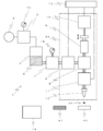
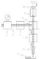
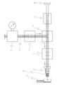
- FIG. 1 shows a view for explaining a discharge device 1 of a dispensing device according to the present embodiment.
- a head portion 34 (a portion surrounded by a dotted line in FIG. 1, which will be described in detail later) constituting the discharge device 1 is movable in the XYZ directions by an XYZ moving mechanism, and the head portion 34 and the dispensing target container 42 are relatively moved. By doing so, the liquid is dispensed.
- the discharge device 1 of the dispensing device includes a nozzle portion having a flow path communicating with a discharge port, a storage portion that supplies a pressure-adjusted liquid pressure transmission medium to the nozzle portion side, and pressure adjustment
- a pressurization unit that supplies the pressurized gas to the storage unit side, a pump mechanism that fluidly communicates with the storage unit and the nozzle unit, and a branch flow path that communicates the nozzle unit, the storage unit, and the pump mechanism.
- a cleaning / drying unit 14 to be configured.
- the nozzle unit includes a nozzle 12 that performs discharge after sucking and temporarily storing the discharge liquid 30.
- the storage unit is a storage container 3 that stores the pressure transmission medium 2, a liquid regulator that is installed between the storage container 3 and the supply valve 6 and adjusts the pressure transmission medium 2 supplied from the storage container 3 to a desired pressure.
- the pressurizing unit is connected to the storage container 3 via a gas pipe and is supplied between the pressurized container 4 and the pressurized gas source 4 for supplying pressurized gas.
- the gas regulator 5 for adjusting the pressurized gas from the gas to a desired pressure is provided.
- the branch portion has a branch block 8 that branches the pressure transmission medium 2 supplied from the storage container 3 in the direction of the pump 9 and the direction of the nozzle 12.
- the pump mechanism includes a pump 9 that is connected to one of the ports of the branch block 8 and sucks and discharges the discharged liquid 30 through the pressure transmission medium 2, and an actuator 10 that operates the pump 9.
- the control unit 13 controls the actuator 10, the supply valve 6, and the discharge valve 11. Details of each device will be described below.
- the storage container 3 of the present embodiment uses a sealed container, and stores the pressure transmission medium 2 therein.
- the pressure transmission medium 2 is made of a liquid, fills the valves (6, 11), the pump 9, the nozzle 12, and the piping connecting them, and plays a role of transmitting the action of pressure to the discharged liquid 30 sucked by the nozzle 12.
- the pressure transmission medium 2 also serves as a cleaning liquid. By discharging the pressure transmission medium 2 from the nozzle 12 together with the discharge liquid 30, the inside of the nozzle 12 (particularly, the portion where the discharge liquid 30 is sucked) is cleaned.
- the pressure transmission medium 2 for example, water or a liquid having a viscosity comparable to that of water is used.
- a pressurized gas source 4 that supplies pressurized gas is connected to the upper part of the storage container 3 via a gas pipe, and a gas regulator that adjusts the pressurized gas to a desired pressure in the middle of the gas pipe. 5 is installed.
- a gas regulator that adjusts the pressurized gas to a desired pressure in the middle of the gas pipe. 5 is installed.
- the gas regulator 5 is preferably provided with a gauge (pressure gauge) 15 for checking the adjustment value.
- the gauge (pressure gauge) 15 may be either an analog type or a digital type.
- the knob attached to the regulator may be turned and adjusted, or may be adjusted by the control unit 13 using an electropneumatic type.
- a dispense controller may be used instead of the gas regulator 5. By using a dispense controller, the pressure value can be easily set and changed.
- a supply valve 6 for starting and stopping the supply of the pressure transmission medium 2 to a pump 9 described later and a nozzle 12 described later is connected to the lower portion of the storage container 3 via a liquid pipe.
- an electromagnetic on-off valve is used as the supply valve 12, and supply of the pressure transmission medium 2 is started and stopped by opening and closing the valve.
- the opening / closing control is performed by the control unit 13 described later.
- a liquid regulator 7 is installed in the middle of the liquid pipe connecting the storage container 3 and the supply valve 6.
- the liquid regulator 7 is preferably provided with a gauge (pressure gauge) 15 for confirming the adjustment value, similarly to the gas regulator 5. Needless to say, the gauge (pressure gauge) 15 may be either an analog type or a digital type.
- the knob attached to the regulator may be turned and adjusted, or may be adjusted by the control unit 13 using an electropneumatic type.
- the pressurized gas supplied from the pressurized gas source 4 is regulated and stabilized by the gas regulator 5, and the stable pressurized gas is supplied.
- the pressure transmission medium 2 on which the pressure acts can be further regulated and stabilized by the liquid regulator 7. Thereby, it is possible to remove the water head difference in the storage container 3, the pressure fluctuation (pulsation) of the pressure source 4, the influence of compressibility, and the like.
- the pressure-regulating / stabilized pressure transmission medium 2 can be supplied to the supply valve 6 related to discharge and the equipment connected to the outlet side thereof.
- the accuracy and stability of discharge can be improved.
- a branch block provided with a flow path for branching the pressure transmission medium 2 supplied from the storage container 3 through the supply valve 6 in the direction of a pump 9 described later and in the direction of a nozzle 12 described later. 8 is connected.
- the flow path in the branch block 8 is formed in a substantially T shape.
- valves (6, 11) and the pump 9 can be directly installed on the block 8, it is possible to reduce the leakage and breakage compared to the case where there is a joint. , Maintenance can be improved.
- a pump 9 that sucks and discharges the discharge liquid 30 through the pressure transmission medium 2.
- a reciprocating positive displacement pump such as a syringe pump or a piston pump (plunger pump) can be used.
- the pump 9 is not used for discharging, but only for sucking and discharging the discharged liquid 30. Further, the pressure transmission medium 2 is not used for pressurization. That is, since the pump 9 is not involved in the operation at the time of discharge, fine control for discharge becomes unnecessary, and the pump 9 does not perform pressurization for discharge. Does not take.
- the pump 9 is provided with an actuator 10 for operating it.
- the actuator 10 for example, a combination of a ball screw and a motor (electric motor) or a direct acting type such as an air cylinder is used corresponding to a reciprocating positive displacement pump.
- the operation of the pump 9 is controlled by controlling the operation of the actuator 10 by the control unit 13 described later.
- the head part 34 to be described later can be configured to be slim and long, and the head parts 34 can be easily arranged side by side. Further, when the head portion 34 is attached to the Z axis, the vertically long head portion is also better.
- a discharge valve 11 that controls discharge by opening and closing the other opening (opening on the lower side in FIG. 1) of the branch block 8 is fluidly communicated.
- a small plunger valve is used as the discharge valve 11.
- other types of valves may be used, but in that case, it is preferable that they can be opened and closed at high speed.
- Discharge is performed by opening and closing the discharge valve 11 at high speed.
- the opening / closing control is performed by the control unit 13 described later.
- a nozzle 12 is fluidly connected to an opening opposite to the opening connected to the branch block 8 of the discharge valve 11. The nozzle 12 is for sucking the discharge liquid 30 from the discharge liquid container 41 and temporarily storing it, and then discharging it to the dispensing target container 42.
- the nozzles 12 are not replaced, and the discharge is performed with one nozzle 12 while cleaning is performed for each dispensing (discharge).
- the tip of the nozzle 12 is preferably coated with a material having water repellency. Examples of the material include fluorine resin and silicon resin. Since the tip of the nozzle 12 is coated with a water-repellent material, the discharge liquid 30 and the cleaning liquid 2 are less likely to remain attached to the outer surface of the nozzle 12 when the discharge liquid 30 is sucked or washed, which is unnecessary. Can prevent dripping and mixing.
- a controller 13 that controls the operation is connected to the actuator 10 that operates the two types of valves (6, 11) and the pump 9 described above.
- the controller 13 controls the opening and closing of the valves (6, 11), the speed and moving distance of the actuator 10, and the like.
- the regulators (5, 7) are electropneumatic, it is also preferable to control them.
- the control unit 13 is sometimes referred to as a “discharge control unit” because it controls discharge.
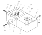
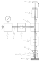
- a cleaning / drying unit 14 that cleans the outer surface of the tip of the nozzle 12 is provided in addition to the above-described devices. Details thereof will be described with reference to FIG.
- the cleaning / drying unit 14 cleans the outer surface of the tip of the nozzle 12 and discharges the discharged liquid 30 remaining after dispensing, and cleans the inner surface of the tip of the nozzle 12, and dries the outer surface of the tip of the nozzle 12 after cleaning. It is divided into a drying unit 17 to be performed.
- the cleaning unit 16 further includes a cleaning unit 18 and a discharge unit 20.
- the cleaning unit 18 includes a spring outlet 18 through which a pipe 19 to which the cleaning liquid 2 is supplied communicates.
- the cleaning liquid 2 stored in the cleaning liquid storage container 36 is supplied to the cleaning unit 16 from the direction of reference numeral 23 in FIG. 2 with the assistance of the pump 38, and the cleaning liquid 2 springs up from the outlet 18 (reference numeral 24).
- cleaning liquid 2 which springs out is a water force like a spring water, and is not the water force which forms a water column at most like a fountain.
- the outer surface of the nozzle 12 can be cleaned by immersing the nozzle 12 in the portion where the cleaning liquid 2 is springing out. Since the cleaning liquid 2 is continuously spouted at the outlet 18, the washed liquid such as the discharged liquid is prevented from flowing back to the cleaning liquid supply side.
- the cleaning liquid 2 is preferably the same liquid as the pressure transmission medium 2 described above.
- the discharge unit 20 is a U-shaped groove formed around the cleaning unit (spring outlet) 18. As shown in FIG. 4, the outer wall of the L-shaped channel connecting the spring outlet 18 and the pipe 19 is in contact with the inner bottom of the cleaning unit 16. Unlike the discharge part 20, it is not a groove, although it is one step lower so as not to overflow.
- the cleaning liquid 2 springed out from the spring outlet 18 passes through the groove of the discharge portion 20 and is discharged from a discharge port 21 opened in the unit wall surface (in the direction of arrow 25).
- the discharge unit 20 also discharges the discharged liquid 30 remaining after dispensing.
- the discharged cleaning liquid 2 and the discharge liquid 30 flow into the waste liquid container 37 through the pipe 22 connected to the discharge port 21. At this time, as with the cleaning unit 18, it is preferable to reliably send the waste liquid with the assistance of the pump 39.
- the drying unit 17 has a hole having a size large enough to insert the tip of the nozzle 12 on its upper surface, in other words, a hole 26 whose diameter is larger than the outer diameter of the nozzle 12.
- the pipe 27 is in fluid communication with the vacuum source 44.
- This hole 26 is called an insertion hole.
- the unit 14 for cleaning and drying including the treatment of the waste liquid and the supply of the cleaning liquid is provided in the nozzle movable range, it is possible to easily perform the cleaning from the tip of the nozzle 12 to the drying, and a series of The operation can be automated.
- the inside and outside of the nozzle 12 can be cleaned and dried by the single unit 14, the cleaning and drying operation in the case of discharging a plurality of types of discharge liquids 30 can be automated.
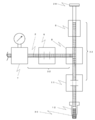
- FIGS. 5 to 11 are diagrams for explaining the dispensing method according to the present embodiment. In these figures, devices between the liquid regulator 5 and the nozzle 12 are shown, and the rest are omitted.
- (1) Supply of pressure transmission medium (FIGS. 5 and 6) As a preparatory stage before discharge, the pressure transmission medium 2 is filled in an empty flow path (substantially T-shaped flow path from the supply valve 6 to the pump 9 and the nozzle 12).
- the piston 29 of the pump 9 is removed from the devices constituting the discharge device 1, the discharge valve 11 is set in the “closed” state, and the supply valve 6 is set in the “closed” state.
- the storage container 3 containing the pressure transmission medium 2 is connected to the inlet side of the supply valve 6, and the pressurized gas source 4 is connected to the storage container 3.
- the gas regulator 5 is adjusted to zero.
- the liquid regulator 7 is adjusted to a discharge pressure described later.
- the gas regulator 5 is adjusted to a predetermined pressure
- the pressure transmission medium 2 is supplied to the inlet of the supply valve 6 by the action of the pressurized gas.
- the set pressure of the gas regulator 5 may be set slightly higher than the set pressure of the liquid regulator 7 in consideration of the loss in the liquid regulator 7 installed on the downstream side.
- the tip of the nozzle 12 is moved onto the discharge unit 20 of the cleaning unit 16 of the cleaning / drying unit 14 by the XYZ moving mechanism.
- the pressure transmission medium 2 is supplied to the tip (outlet side) of the supply valve 6 by the action of the pressurized gas. Then, as shown in FIG. 5, a part of the pressure transmission medium 2 also flows in the direction of the nozzle 12, but first flows in the direction of the pump 9. When the pressure transmission medium 2 reaches the upper end of the pump 9 or overflows, the supply valve 6 is closed. The piston 29 that has been removed is inserted, and the piston end is fixed to the actuator. When both the discharge valve 11 and the supply valve 6 are in the “open” state, as shown in FIG. 6, the pressure transmission medium 2 flows toward the nozzle 12 and finally flows out from the tip of the nozzle 12.
- the pressure transmission medium 2 and the discharge liquid 30 are mixed with each other.
- an amount of about 10% of the amount of one drop is sucked.
- the tip of the nozzle 12 is immersed in the discharge liquid 30, and the piston 29 of the pump 9 is retracted to suck the discharge liquid 30.
- the suction amount is adjusted by the retraction amount of the piston 29 of the pump 9.
- the amount of the discharge liquid 30 to be sucked is preferably slightly larger than the total amount to be dispensed.
- the tip portion of the nozzle 12 has a length that can store an amount to be dispensed at a time (for example, the total amount when discharging to all the concave portions of a plate integrally provided with a plurality of concave portions). It is preferable to do.
- the diameter of the nozzle 12 is appropriately selected according to the amount of one droplet to be discharged. For example, in the present embodiment, a tapered conical nozzle having an inner diameter of about 0.1 [mm] and a tip portion having a length of 5 to 10 [mm] is used.
- the pressurized gas supplied from the pressurized gas source 4 is regulated and stabilized by the gas regulator 5, and the stable pressurized gas is supplied. Since the pressure transmission medium 2 on which the pressure acts is further regulated and stabilized by the liquid regulator 7, the effects of the water head difference in the storage container 3, pressure fluctuation (pulsation) of the pressure source 4, and compressibility are eliminated. can do.
- the discharge liquid 30 in the flow path from the outlet side of the discharge valve 11 to the nozzle 12 has not been pressurized yet. However, as described above, the distance from the discharge valve 11 to the nozzle 12 is configured to be as short as possible, so that the pressure at the time of discharge is transmitted promptly.
- the set value of the pressure of the liquid regulator 7 is obtained in advance by an experiment or the like depending on the amount of one drop or whether or not to fly. However, it is necessary to consider it together with the valve opening / closing time described later (see (4) below for specific numerical examples).
- Discharge of discharged liquid (FIG. 9) Discharge is started when pressurization of the pressure transmission medium is completed.
- the head part 34 described later is moved by the XYZ moving mechanism so that the tip of the nozzle 12 is positioned above the target container 42 for dispensing.
- the discharge valve 11 is in the “open” state, pressure is transmitted to the discharge liquid 30 in the nozzle 12 on the outlet side of the discharge valve 11 via the pressure transmission medium 2, and the discharge liquid 30 starts to flow out of the nozzle 12.
- the discharge valve 11 is in the “closed” state after a predetermined time has elapsed, the pressure transmission is stopped and the discharge of the discharge liquid 30 from the nozzle 12 is stopped.
- the discharge liquid 30 is made to drop and fly from the nozzle 12 to be dispensed target containers. 42 can be discharged to a dispensing position. Further, if the discharge method is based on the action of pressure from the pressurized gas source 4, flight discharge in which the amount of one drop, which is difficult with the discharge method based on the action of the piston 29, is also possible. When there are a plurality of dispensing positions in the dispensing target container 42, the movement of the nozzle 12 and the opening and closing of the discharge valve 11 are repeated.
- the set value of the time is obtained in advance by an experiment or the like depending on the amount of one drop and whether or not to fly, like the pressure value.
- the discharge amount is mainly adjusted by the valve opening / closing time.
- the pressure setting is rarely changed once determined. This is because time is more responsive than pressure.
- the time and the discharge amount are in a substantially proportional relationship, the setting can be adjusted relatively easily.
- a pressure of 30 [kPa] (kilopascal) is applied to a discharge liquid having a viscosity of about 1 [mPa ⁇ s] (millipascal second), and a 1 [msec] (millisecond) discharge valve is set.
- Discharging / cleaning / drying (FIG. 10)
- the discharged liquid 30 remaining in the nozzle 12 is discharged, and at the same time, the inside and outside of the nozzle 12 are cleaned.
- the discharge valve 11 is set to the “closed” state, and the head unit 34 (to be described later) is moved by the XYZ moving mechanism so that the tip of the nozzle 12 is positioned at the discharge unit 20 of the cleaning unit 16 of the cleaning / drying unit 14. Subsequently, the discharge valve 11 is opened and the discharge liquid 30 remaining in the nozzle 12 is discharged.
- the discharge liquid 30 in the nozzle 12 is discharged together with the pressure transmission medium 2 while being pushed out by the pressure transmission medium 2.
- the pressure transmission medium 2 that also serves as the cleaning liquid 2 can clean the inner surface of the nozzle 12 tip.
- the nozzle 12 is preferably positioned below the upper end of the wall surface of the discharge unit 20 of the cleaning unit 14 by the XYZ moving mechanism so as not to scatter.
- the discharge valve 11 is set to the “closed” state.
- the tip of the nozzle 12 is moved by the XYZ moving mechanism to the cleaning unit 18 of the cleaning unit 16 of the cleaning / drying unit 14, and the outer surface of the nozzle 12 is cleaned with the cleaning liquid 2 that comes from the cleaning unit 18.
- the nozzle 12 When cleaning the nozzle 12, the nozzle 12 is not inserted into the spring outlet 18, but may be immersed in a portion that is springing over the spring outlet 18. When it is desired to change the region of the nozzle 12 to be cleaned, it may be changed by adjusting the water flow from which the cleaning liquid 2 is swelled.
- the cleaning liquid 2 is preferably the same as the pressure transmission medium 2. This is because if the cleaning liquid 2 and the pressure transmission medium 2 are different, the cleaning liquid 2 and the pressure transmission medium 2 are mixed in the portion immersed in the cleaning liquid 2 at the tip of the nozzle 12.
- the tip of the nozzle 12 is moved onto the drying unit 17 of the cleaning / drying unit 14 by the XYZ moving mechanism, and the tip of the nozzle 12 is inserted into the insertion hole 26. Then, the tip of the nozzle 12 is dried by sucking the air around the nozzle 12 and sucking the excess liquid (mainly the cleaning liquid 2) adhering to the outer surface of the nozzle 12. In this way, the cleaning liquid or the like is not adhered to the outer surface of the tip of the nozzle 12 but is kept dry, so that the next time the suction of the discharge liquid 30 is performed, the mixing of the cleaning liquid 2 and the discharge liquid 30 is ensured. It becomes possible to prevent.
- the pressure transmission medium 2 corresponding to the advancement of the piston 29 is discharged from the nozzle 12 to the discharge unit 20 of the cleaning unit 16.
- the pressurized gas supplied from the pressurized gas source 4 is used as the gas regulator. Since the pressure transmission medium 2 that is regulated and stabilized at 5 and the stable pressurized gas acts is further regulated and stabilized by the liquid regulator 7, the water head difference in the storage container 3 and the pressure source 4 Pressure fluctuation (pulsation), compressive effects, etc. can be removed. Further, by providing the liquid regulator 7 in front of the inlet of the supply valve 6, the pressure-regulating / stabilized pressure transmission medium 2 can be supplied to the supply valve 6 related to discharge and the equipment connected to the outlet side thereof. In addition, the accuracy and stability of discharge can be improved.
- the unit 14 for cleaning and drying including waste liquid processing and cleaning liquid supply is provided in the nozzle movable range, the nozzle 12 tip can be cleaned and dried quickly and easily. The operation can be automated. Then, the cleaning liquid or the like is not left attached to the outer surface of the tip of the nozzle 12, but when the discharge liquid is sucked next time, it is possible to reliably prevent the mixing of the cleaning liquid and the discharge liquid. Become.
- the inside and outside of the nozzle 12 can be cleaned and dried by the single unit 14, the cleaning and drying operation in the case of discharging a plurality of types of discharge liquids 30 can be automated.
- the discharge liquid 30 is made to drop and fly from the nozzle 12 to the target. It is possible to discharge.
- the discharge method is based on the action of pressure, it is possible to perform flight discharge in which the amount of one drop, which is difficult with the discharge method based on the action of the piston 29, is very small.
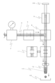
- FIG. 12 is a diagram illustrating the overall configuration of the dispensing apparatus according to the present embodiment.
- the dispensing device 33 according to the present embodiment includes a discharge device 1 that performs suction and discharge of the discharge liquid 30 and cleaning of the nozzle 12, a work table 40 on which the dispensing target container 42 and the discharge liquid container 41 are placed.
- An XYZ moving mechanism that relatively moves the nozzle 12 and the work table 40 is a main element. Details of each will be described below.
- Discharge device The basic configuration is the same as that shown in FIG. 1, but the installation location differs for each device.
- the nozzle 12, the branch block 8, the pump 9, the actuator 10, and the supply valve 6 are integrally attached to one base and installed in a Z moving mechanism 47 described later.
- a group attached to the base is referred to as a head portion 34 (portion surrounded by a dotted line in FIG. 1).
- the head portion 34 is covered with a cover except for the nozzle 12 portion.
- the liquid regulator 7, the storage container 3, and the gas regulator 5 are installed on the side of the casing of the dispensing device 33.
- the regulators (5, 7) and the storage container 3 are installed separately from the head part 34.
- the storage container 3 may be an airtight container as described in the embodiment, regardless of the material, shape, and the like.
- a syringe used in a tank, a bottle, or an air dispenser may be used.
- an analog type is drawn as the gauge (pressure gauge) 15 attached to each regulator (5, 7), but it goes without saying that a digital type may be used.
- a dispense controller may be used instead of the gas regulator.
- the supply valve 6 of the head unit 34 and the liquid regulator 7 are connected by a pipe 35 illustrated by a dotted line.
- the pipe 35 is preferably made of a flexible material in consideration of the movement of the head portion 34.
- the pressurized gas source 4 is provided separately from the dispensing device 33 and is connected to the gas regulator 5 via a pipe.
- the illustration is simplified. As a specific example, it is disclosed to use a general compressor or to receive supply directly from factory equipment.
- the cleaning / drying unit 14 is installed at a position that does not interfere with the table movement on the upper surface of the casing beside the work table 40.
- the cleaning / drying unit 14 has the same configuration as in FIG. 2, and includes a cleaning unit 16 and a drying unit 17.
- the cleaning liquid container 36, the waste liquid container 37, the cleaning liquid pump 38, and the waste liquid pump 39 attached to the cleaning unit 16 are arranged on the side surface of the main body of the dispensing device 33 on the side of the casing opposite to the regulator (5, 7). Installed in an adjacent position.
- the cleaning unit 16 is connected to the cleaning liquid container 36 and the waste liquid container 37 by piping through the cleaning liquid pump 38 and the waste liquid pump 39, respectively.
- the discharge controller 13 is installed on the side surface of the dispensing device 33 housing on the cleaning / drying unit 14 side.
- the discharge controller 13 controls the operation of the actuator 10 that operates the pump 9 and the two types of valves (6, 11).
- the discharge controller 13 also controls operations of the cleaning liquid pump 38 and the waste liquid pump 39 provided in the above-described cleaning unit 16.
- the worktable 40 has a discharge liquid container 41 and a dispensing target container 42 placed on the upper surface thereof.
- these containers (41, 42) have a plate shape in which a plurality of recesses (wells) are integrally provided, and a plurality of types of samples / reagents and specimens are contained in the plurality of recesses. Then, the sample / reagent in the recess is aspirated or the sample / reagent is discharged toward the recess to perform analysis and inspection.
- a method of fixing each of the containers (41, 42) a method of making a plurality of holes leading from the inside of the table 40 to the upper surface and sucking and fixing the air by sucking air from the holes, and sandwiching the container with a fixing member
- a method of fixing the container by fixing the member to the table 40 with fixing means such as a screw can be used.
- suction fixation it is necessary to connect a vacuum source 44 separately.
- Adsorption fixation may be employed if handling is easy.
- a vacuum control unit 43 for controlling the negative pressure gas used for suction in the drying unit 17 and suction fixing in the work table 40 is provided in the housing of the dispensing device 33. It is installed on the side of the body.
- the vacuum source 44 is provided separately from the dispensing device 33 and is connected to the vacuum control unit 43 by piping.
- Each of the containers (41, 42) can be placed at a position that does not interfere with the movement of the work table 40 as in the cleaning / drying unit 14, but if the work table 40 has sufficient space, it is placed together. It is better to end up. This is because the moving distance between the discharge liquid container 41 and the dispensing target container 42 is shortened, and the working time is shortened accordingly.
- the XYZ moving mechanism is installed on a gate-shaped frame, and moves the Z moving mechanism 47 on which the head unit 34 is installed in the direction of reference numeral 48, and the X moving mechanism 45 It is installed on the Y movement mechanism 46 for moving the work table 40 in the direction of reference numeral 49 and the Z movement mechanism 47 for moving the head unit 34 in the direction of reference numeral 50.
- a control unit (not shown) for the moving mechanism is provided in the housing under the Y moving mechanism 46.
- the control unit also controls the XYZ movement operation and transmits an operation signal to the discharge control unit 13 that controls the discharge device 1. Further, it has a storage device (not shown) for storing a coating program in which the XYZ movement operation, the discharge operation timing, and the like are routineized.
- the ejection liquid of this example is a reagent for detecting blood and urine, and antigens and antibodies from them, and 96 (8 ⁇ 12) wells are dispensed in a volume of 20 to 30 nL (nanoliter). Dispense into the formed microplate.
- the discharge liquid container 41 and the dispensing target container 42 are placed on the work table 40 and fixed.
- the storage container 3 containing the pressure transmission medium 2, the cleaning liquid container 36, and the waste liquid container 37 are installed, and the piping is connected to the pumps (38, 39), the head unit 34, and the like.
- the supply of the pressure transmission medium 2 and the suction and pressurization of the discharge liquid 30 are performed in accordance with the procedure of FIGS. 5 to 11 shown in the embodiment.
- the head part 34 is moved with respect to the dispensing target container 42, and the discharge liquid 30 is discharged (refer FIG. 9).
- the head unit 34 is not stopped every time the recesses are positioned above the recesses, but if the discharge is performed while moving, the working time can be shortened. it can.
- the discharge liquid 30 that has been dispensed is discharged, washed, and dried in accordance with the discharge / cleaning / drying procedure described in the embodiment.
- the discharge liquid 30 is sucked and discharged (see FIGS. 10 and 11). If another discharge liquid 30 is to be discharged, the above-described discharge / cleaning / drying / suction / discharge steps are repeated.
- finishing the work it is preferable to finish the whole work after finishing the discharging, washing and drying processes.
- the dispensing device 33 of Example 1 can achieve a high accuracy of about 1 to 0.5% as the dispensing accuracy as a variation in the discharge amount.
Landscapes
- Chemical & Material Sciences (AREA)
- Health & Medical Sciences (AREA)
- Analytical Chemistry (AREA)
- Physics & Mathematics (AREA)
- Clinical Laboratory Science (AREA)
- Chemical Kinetics & Catalysis (AREA)
- Biochemistry (AREA)
- Life Sciences & Earth Sciences (AREA)
- General Health & Medical Sciences (AREA)
- General Physics & Mathematics (AREA)
- Immunology (AREA)
- Pathology (AREA)
- Fluid Mechanics (AREA)
- Feeding, Discharge, Calcimining, Fusing, And Gas-Generation Devices (AREA)
- Sampling And Sample Adjustment (AREA)
- Automatic Analysis And Handling Materials Therefor (AREA)
- Containers And Packaging Bodies Having A Special Means To Remove Contents (AREA)
Priority Applications (5)
| Application Number | Priority Date | Filing Date | Title |
|---|---|---|---|
| KR1020127028258A KR101769835B1 (ko) | 2010-03-30 | 2011-03-24 | 토출 장치 및 액체 분주 장치, 및 액체 분주 방법 |
| HK13102874.2A HK1175537B (en) | 2010-03-30 | 2011-03-24 | Discharge device and liquid dispensing device, and method for dispensing liquid |
| EP11762656.4A EP2555000B1 (en) | 2010-03-30 | 2011-03-24 | Discharge device and liquid dispensing device, and method for dispensing liquid |
| CN201180018042.2A CN102869994B (zh) | 2010-03-30 | 2011-03-24 | 吐出装置和液体分注装置以及液体分注方法 |
| US13/638,718 US9186667B2 (en) | 2010-03-30 | 2011-03-24 | Discharge device and liquid dispensing device, and method for dispensing liquid |
Applications Claiming Priority (2)
| Application Number | Priority Date | Filing Date | Title |
|---|---|---|---|
| JP2010-078176 | 2010-03-30 | ||
| JP2010078176A JP5646196B2 (ja) | 2010-03-30 | 2010-03-30 | 吐出装置および液体分注装置並びに液体分注方法 |
Publications (1)
| Publication Number | Publication Date |
|---|---|
| WO2011122425A1 true WO2011122425A1 (ja) | 2011-10-06 |
Family
ID=44712134
Family Applications (1)
| Application Number | Title | Priority Date | Filing Date |
|---|---|---|---|
| PCT/JP2011/057107 Ceased WO2011122425A1 (ja) | 2010-03-30 | 2011-03-24 | 吐出装置および液体分注装置並びに液体分注方法 |
Country Status (7)
| Country | Link |
|---|---|
| US (1) | US9186667B2 (OSRAM) |
| EP (1) | EP2555000B1 (OSRAM) |
| JP (1) | JP5646196B2 (OSRAM) |
| KR (1) | KR101769835B1 (OSRAM) |
| CN (1) | CN102869994B (OSRAM) |
| TW (1) | TWI521209B (OSRAM) |
| WO (1) | WO2011122425A1 (OSRAM) |
Cited By (1)
| Publication number | Priority date | Publication date | Assignee | Title |
|---|---|---|---|---|
| CN104833614A (zh) * | 2014-01-24 | 2015-08-12 | 克吕士科学实验仪器有限公司 | 接触角测量设备 |
Families Citing this family (43)
| Publication number | Priority date | Publication date | Assignee | Title |
|---|---|---|---|---|
| US9670809B2 (en) | 2011-11-29 | 2017-06-06 | Corning Incorporated | Apparatus and method for skinning articles |
| JP2014119387A (ja) * | 2012-12-18 | 2014-06-30 | Sony Corp | 分注装置、分析装置及び分注装置の制御方法 |
| JP6057754B2 (ja) * | 2013-02-08 | 2017-01-11 | 株式会社日立ハイテクノロジーズ | 臨床用自動分析装置および方法 |
| US9519002B2 (en) * | 2013-04-11 | 2016-12-13 | Rarecyte, Inc. | Device, system, and method for selecting a target analyte |
| CN104120586A (zh) * | 2013-04-26 | 2014-10-29 | 合肥海尔洗衣机有限公司 | 一种装有液体投放装置的洗衣机及其控制方法 |
| JP6445974B2 (ja) * | 2013-10-05 | 2019-01-09 | 武蔵エンジニアリング株式会社 | 液体材料充填装置および方法 |
| US10611051B2 (en) | 2013-10-15 | 2020-04-07 | Corning Incorporated | Systems and methods for skinning articles |
| US9239296B2 (en) | 2014-03-18 | 2016-01-19 | Corning Incorporated | Skinning of ceramic honeycomb bodies |
| EP2878954A1 (en) * | 2013-11-28 | 2015-06-03 | F. Hoffmann-La Roche AG | Pipetting method and system |
| ES2989190T3 (es) * | 2014-07-28 | 2024-11-25 | Lgc Genomics Llc | Instrumento para analizar muestras biológicas y reactivos |
| US9469263B2 (en) | 2014-08-06 | 2016-10-18 | Honda Motor Co., Ltd. | Systems and methods for filling a vehicle component with fluid |
| KR101492942B1 (ko) * | 2014-09-11 | 2015-02-12 | (주) 디바이스이엔지 | 액체공급장치 및 액체공급방법 |
| JP6452147B2 (ja) * | 2015-01-19 | 2019-01-16 | 武蔵エンジニアリング株式会社 | 液体材料吐出装置 |
| JP6506077B2 (ja) * | 2015-03-31 | 2019-04-24 | シスメックス株式会社 | 尿検体分析装置、尿検体分注方法及び尿検体処理方法 |
| JP6676300B2 (ja) * | 2015-07-28 | 2020-04-08 | ヤマハ発動機株式会社 | 対象物移動方法及び装置 |
| JP2017142461A (ja) * | 2016-02-12 | 2017-08-17 | セイコーインスツル株式会社 | フェルール洗浄装置、フェルール洗浄方法およびフェルール洗浄プログラム |
| CN109070148B (zh) * | 2016-05-11 | 2022-02-01 | 西门子医疗保健诊断公司 | 用于分析仪器的探针清洗站 |
| CN109152992B (zh) * | 2016-05-23 | 2022-09-30 | 贝克顿·迪金森公司 | 具有用于模块化的独立致动的移液管通道的歧管安装件的液体分配器 |
| JP6835506B2 (ja) * | 2016-09-01 | 2021-02-24 | Ntn株式会社 | 液体塗布ユニットおよび液体塗布装置 |
| JP6778426B2 (ja) * | 2016-09-20 | 2020-11-04 | 武蔵エンジニアリング株式会社 | 液体材料吐出装置 |
| KR101835812B1 (ko) * | 2016-10-25 | 2018-03-07 | 현세환 | 디스플레이패널 제조용 디스펜서 |
| WO2018091075A1 (en) * | 2016-11-15 | 2018-05-24 | Tecan Schweiz Ag | Pipetting method and pipetting device |
| JP6161842B1 (ja) | 2017-02-15 | 2017-07-12 | 株式会社渡辺製作所 | 液滴噴出装置 |
| JP7019303B2 (ja) * | 2017-03-24 | 2022-02-15 | 東芝テック株式会社 | 液滴分注装置 |
| CN107505236A (zh) * | 2017-09-13 | 2017-12-22 | 宁波新边界科学仪器有限公司 | 一种具有新型液体分配方法的接触角测量方法及其装置 |
| DE102017216713B4 (de) * | 2017-09-21 | 2020-07-30 | Festo Se & Co. Kg | Verfahren und Dosiervorrichtung zur dosierten Fluidausgabe |
| JP6935023B2 (ja) * | 2018-09-27 | 2021-09-15 | 株式会社日立ハイテク | 自動分析装置および洗浄方法 |
| EP3927468B1 (en) * | 2019-02-18 | 2025-05-07 | CTC Analytics AG | Fluid delivery device and method for carrying out chemical or biological assays |
| US11320295B2 (en) * | 2019-04-26 | 2022-05-03 | Festo Se & Co. Kg | Dosing unit and method for dosing a liquid |
| US12257850B2 (en) * | 2019-08-30 | 2025-03-25 | Kyocera Corporation | Circulation device |
| KR102299717B1 (ko) * | 2020-01-22 | 2021-09-08 | 주식회사 임진과학 | 시약을 자동으로 공급하기 위한 시약공급장치 |
| CN113058783B (zh) * | 2021-03-17 | 2022-05-13 | 马鞍山远荣机器人智能装备有限公司 | 一种便于喷头清洗的汽车喷涂装置 |
| CN112940909B (zh) * | 2021-03-29 | 2025-07-25 | 广州斯智生物科技有限公司 | 样本精控仪及其使用方法 |
| DE112021007926T5 (de) * | 2021-09-14 | 2024-04-18 | Hitachi High-Tech Corporation | Abgabevorrichtung und abgabeverfahren |
| DE112021007927T5 (de) * | 2021-09-14 | 2024-04-18 | Hitachi High-Tech Corporation | Abgabevorrichtung und abgabeverfahren |
| KR102591204B1 (ko) * | 2022-01-04 | 2023-10-19 | 재단법인대구경북과학기술원 | 희토자석용 중희토 확산물질 분사 장치 |
| KR102646741B1 (ko) | 2022-06-23 | 2024-03-11 | 동의대학교 산학협력단 | 액적 토출 모니터링이 가능한 공압 디스펜서 |
| CN115041246B (zh) * | 2022-07-15 | 2023-04-18 | 成都瀚辰光翼科技有限责任公司 | 移液器控制方法及装置、移液控制设备和可读存储介质 |
| CN115266478A (zh) * | 2022-08-23 | 2022-11-01 | 上海梭伦信息科技有限公司 | 一种除冰润湿性表征的测试装置和方法 |
| EP4644699A1 (en) * | 2022-12-26 | 2025-11-05 | Hitachi High-Tech Corporation | Liquid ejection device |
| JPWO2024219094A1 (OSRAM) * | 2023-04-20 | 2024-10-24 | ||
| DE102023132501B3 (de) | 2023-11-22 | 2025-02-13 | Festo Se & Co. Kg | Dosiereinrichtung zur Dosierung von Flüssigkeiten |
| CN117969543B (zh) * | 2024-01-31 | 2024-07-26 | 湖北鸿冶管业科技有限公司 | 一种焊管检测装置及其方法 |
Citations (7)
| Publication number | Priority date | Publication date | Assignee | Title |
|---|---|---|---|---|
| JPS62182665A (ja) | 1985-10-15 | 1987-08-11 | Toyo Soda Mfg Co Ltd | 微量液の分注方法およびこれに用いる装置 |
| JPH0943251A (ja) * | 1995-08-03 | 1997-02-14 | Olympus Optical Co Ltd | 分注器 |
| JPH1096735A (ja) | 1996-09-25 | 1998-04-14 | Aloka Co Ltd | 空中吐出式分注装置 |
| JP2005257491A (ja) * | 2004-03-12 | 2005-09-22 | Hitachi High-Technologies Corp | 自動分析装置 |
| JP2006284426A (ja) | 2005-04-01 | 2006-10-19 | Matsushita Electric Ind Co Ltd | 分注装置及び分注方法 |
| JP2006308374A (ja) | 2005-04-27 | 2006-11-09 | Aida Eng Ltd | 液体分注装置及び液体分注方法 |
| JP2007278978A (ja) * | 2006-04-11 | 2007-10-25 | Olympus Corp | 分注装置 |
Family Cites Families (7)
| Publication number | Priority date | Publication date | Assignee | Title |
|---|---|---|---|---|
| US6309600B1 (en) * | 1997-08-28 | 2001-10-30 | Biotrove, Inc. | Apparatus for droplet microchemistry |
| JP2003514592A (ja) * | 1999-09-14 | 2003-04-22 | ファーマコペイア インコーポレイテッド | 液体ディスペンサで使用される流れ制御部材 |
| JP3863820B2 (ja) * | 2002-07-25 | 2006-12-27 | 株式会社アルファテクノ | 精密分注装置 |
| US7195026B2 (en) * | 2002-12-27 | 2007-03-27 | American Air Liquide, Inc. | Micro electromechanical systems for delivering high purity fluids in a chemical delivery system |
| EP2305171B1 (en) * | 2003-03-28 | 2021-12-29 | Inguran, LLC | Apparatus and methods for providing sex-sorted animal sperm |
| US20080227663A1 (en) * | 2007-01-19 | 2008-09-18 | Biodot, Inc. | Systems and methods for high speed array printing and hybridization |
| JP5203979B2 (ja) * | 2008-02-06 | 2013-06-05 | 株式会社東芝 | 自動分析装置 |
-
2010
- 2010-03-30 JP JP2010078176A patent/JP5646196B2/ja active Active
-
2011
- 2011-03-24 EP EP11762656.4A patent/EP2555000B1/en active Active
- 2011-03-24 CN CN201180018042.2A patent/CN102869994B/zh active Active
- 2011-03-24 WO PCT/JP2011/057107 patent/WO2011122425A1/ja not_active Ceased
- 2011-03-24 US US13/638,718 patent/US9186667B2/en active Active
- 2011-03-24 KR KR1020127028258A patent/KR101769835B1/ko active Active
- 2011-03-30 TW TW100110981A patent/TWI521209B/zh active
Patent Citations (7)
| Publication number | Priority date | Publication date | Assignee | Title |
|---|---|---|---|---|
| JPS62182665A (ja) | 1985-10-15 | 1987-08-11 | Toyo Soda Mfg Co Ltd | 微量液の分注方法およびこれに用いる装置 |
| JPH0943251A (ja) * | 1995-08-03 | 1997-02-14 | Olympus Optical Co Ltd | 分注器 |
| JPH1096735A (ja) | 1996-09-25 | 1998-04-14 | Aloka Co Ltd | 空中吐出式分注装置 |
| JP2005257491A (ja) * | 2004-03-12 | 2005-09-22 | Hitachi High-Technologies Corp | 自動分析装置 |
| JP2006284426A (ja) | 2005-04-01 | 2006-10-19 | Matsushita Electric Ind Co Ltd | 分注装置及び分注方法 |
| JP2006308374A (ja) | 2005-04-27 | 2006-11-09 | Aida Eng Ltd | 液体分注装置及び液体分注方法 |
| JP2007278978A (ja) * | 2006-04-11 | 2007-10-25 | Olympus Corp | 分注装置 |
Non-Patent Citations (1)
| Title |
|---|
| See also references of EP2555000A4 |
Cited By (1)
| Publication number | Priority date | Publication date | Assignee | Title |
|---|---|---|---|---|
| CN104833614A (zh) * | 2014-01-24 | 2015-08-12 | 克吕士科学实验仪器有限公司 | 接触角测量设备 |
Also Published As
| Publication number | Publication date |
|---|---|
| CN102869994B (zh) | 2015-07-29 |
| TWI521209B (zh) | 2016-02-11 |
| EP2555000A4 (en) | 2017-12-20 |
| JP2011209153A (ja) | 2011-10-20 |
| JP5646196B2 (ja) | 2014-12-24 |
| US20130108521A1 (en) | 2013-05-02 |
| KR101769835B1 (ko) | 2017-08-21 |
| HK1175537A1 (en) | 2013-07-05 |
| EP2555000A1 (en) | 2013-02-06 |
| US9186667B2 (en) | 2015-11-17 |
| TW201207398A (en) | 2012-02-16 |
| KR20130064063A (ko) | 2013-06-17 |
| EP2555000B1 (en) | 2019-02-27 |
| CN102869994A (zh) | 2013-01-09 |
Similar Documents
| Publication | Publication Date | Title |
|---|---|---|
| JP5646196B2 (ja) | 吐出装置および液体分注装置並びに液体分注方法 | |
| US8900530B2 (en) | Micro-volume liquid ejection system | |
| JP4813680B2 (ja) | ガスクッション式分配マイクロシステム | |
| US8597592B2 (en) | Microvalve controlled precision fluid dispensing apparatus with a self-purging feature and method for use | |
| US6551557B1 (en) | Tip design and random access array for microfluidic transfer | |
| EP2846915B1 (en) | Microfluidic dispenser, cartridge and analysis system for analyzing a biological sample | |
| US7303728B2 (en) | Fluid dispensing device | |
| EP1129008A2 (en) | Tip design and random access array for microfluidic transfer | |
| US20120024888A1 (en) | Cleaning of system for dispensing of liquid droplets | |
| EP2075586A1 (en) | Dispenser | |
| JP5050859B2 (ja) | 分注方法および分注装置 | |
| JP2009162536A (ja) | 液体試料分注装置および駆動方法 | |
| JP2006308374A (ja) | 液体分注装置及び液体分注方法 | |
| CN115200655A (zh) | 计量装置和计量液体介质的方法 | |
| CN110505920B (zh) | 用于接触计量液体的方法和计量装置 | |
| HK1175537B (en) | Discharge device and liquid dispensing device, and method for dispensing liquid | |
| US20080041488A1 (en) | Fluid dispensing system for semiconductor manufacturing processes with self-cleaning dispense valve | |
| TW201932197A (zh) | 流體分配器 | |
| CN112390217A (zh) | 一种用于分配微体积液体的装置 | |
| JP2004361267A (ja) | 液体分注装置およびその気泡発生防止方法 | |
| JP2008232632A (ja) | 液体試料分注装置および駆動方法 | |
| KR20130051245A (ko) | 접착액 도포 장치 및 이를 이용한 접착액 도포 방법 |
Legal Events
| Date | Code | Title | Description |
|---|---|---|---|
| WWE | Wipo information: entry into national phase |
Ref document number: 201180018042.2 Country of ref document: CN |
|
| 121 | Ep: the epo has been informed by wipo that ep was designated in this application |
Ref document number: 11762656 Country of ref document: EP Kind code of ref document: A1 |
|
| DPE1 | Request for preliminary examination filed after expiration of 19th month from priority date (pct application filed from 20040101) | ||
| NENP | Non-entry into the national phase |
Ref country code: DE |
|
| WWE | Wipo information: entry into national phase |
Ref document number: 2011762656 Country of ref document: EP |
|
| ENP | Entry into the national phase |
Ref document number: 20127028258 Country of ref document: KR Kind code of ref document: A |
|
| WWE | Wipo information: entry into national phase |
Ref document number: 13638718 Country of ref document: US |