WO2011122425A1 - Discharge device and liquid dispensing device, and method for dispensing liquid - Google Patents
Discharge device and liquid dispensing device, and method for dispensing liquid Download PDFInfo
- Publication number
- WO2011122425A1 WO2011122425A1 PCT/JP2011/057107 JP2011057107W WO2011122425A1 WO 2011122425 A1 WO2011122425 A1 WO 2011122425A1 JP 2011057107 W JP2011057107 W JP 2011057107W WO 2011122425 A1 WO2011122425 A1 WO 2011122425A1
- Authority
- WO
- WIPO (PCT)
- Prior art keywords
- liquid
- discharge
- nozzle
- unit
- transmission medium
- Prior art date
Links
Images


Classifications
-
- B—PERFORMING OPERATIONS; TRANSPORTING
- B01—PHYSICAL OR CHEMICAL PROCESSES OR APPARATUS IN GENERAL
- B01L—CHEMICAL OR PHYSICAL LABORATORY APPARATUS FOR GENERAL USE
- B01L3/00—Containers or dishes for laboratory use, e.g. laboratory glassware; Droppers
- B01L3/02—Burettes; Pipettes
- B01L3/0289—Apparatus for withdrawing or distributing predetermined quantities of fluid
- B01L3/0293—Apparatus for withdrawing or distributing predetermined quantities of fluid for liquids
-
- B—PERFORMING OPERATIONS; TRANSPORTING
- B01—PHYSICAL OR CHEMICAL PROCESSES OR APPARATUS IN GENERAL
- B01L—CHEMICAL OR PHYSICAL LABORATORY APPARATUS FOR GENERAL USE
- B01L3/00—Containers or dishes for laboratory use, e.g. laboratory glassware; Droppers
- B01L3/02—Burettes; Pipettes
- B01L3/0241—Drop counters; Drop formers
- B01L3/0265—Drop counters; Drop formers using valves to interrupt or meter fluid flow, e.g. using solenoids or metering valves
-
- B—PERFORMING OPERATIONS; TRANSPORTING
- B05—SPRAYING OR ATOMISING IN GENERAL; APPLYING FLUENT MATERIALS TO SURFACES, IN GENERAL
- B05B—SPRAYING APPARATUS; ATOMISING APPARATUS; NOZZLES
- B05B15/00—Details of spraying plant or spraying apparatus not otherwise provided for; Accessories
- B05B15/50—Arrangements for cleaning; Arrangements for preventing deposits, drying-out or blockage; Arrangements for detecting improper discharge caused by the presence of foreign matter
- B05B15/55—Arrangements for cleaning; Arrangements for preventing deposits, drying-out or blockage; Arrangements for detecting improper discharge caused by the presence of foreign matter using cleaning fluids
- B05B15/555—Arrangements for cleaning; Arrangements for preventing deposits, drying-out or blockage; Arrangements for detecting improper discharge caused by the presence of foreign matter using cleaning fluids discharged by cleaning nozzles
-
- G—PHYSICS
- G01—MEASURING; TESTING
- G01N—INVESTIGATING OR ANALYSING MATERIALS BY DETERMINING THEIR CHEMICAL OR PHYSICAL PROPERTIES
- G01N35/00—Automatic analysis not limited to methods or materials provided for in any single one of groups G01N1/00 - G01N33/00; Handling materials therefor
- G01N35/10—Devices for transferring samples or any liquids to, in, or from, the analysis apparatus, e.g. suction devices, injection devices
- G01N35/1004—Cleaning sample transfer devices
-
- B—PERFORMING OPERATIONS; TRANSPORTING
- B01—PHYSICAL OR CHEMICAL PROCESSES OR APPARATUS IN GENERAL
- B01L—CHEMICAL OR PHYSICAL LABORATORY APPARATUS FOR GENERAL USE
- B01L2200/00—Solutions for specific problems relating to chemical or physical laboratory apparatus
- B01L2200/06—Fluid handling related problems
- B01L2200/0673—Handling of plugs of fluid surrounded by immiscible fluid
-
- B—PERFORMING OPERATIONS; TRANSPORTING
- B01—PHYSICAL OR CHEMICAL PROCESSES OR APPARATUS IN GENERAL
- B01L—CHEMICAL OR PHYSICAL LABORATORY APPARATUS FOR GENERAL USE
- B01L2400/00—Moving or stopping fluids
- B01L2400/04—Moving fluids with specific forces or mechanical means
- B01L2400/0475—Moving fluids with specific forces or mechanical means specific mechanical means and fluid pressure
- B01L2400/0478—Moving fluids with specific forces or mechanical means specific mechanical means and fluid pressure pistons
-
- B—PERFORMING OPERATIONS; TRANSPORTING
- B01—PHYSICAL OR CHEMICAL PROCESSES OR APPARATUS IN GENERAL
- B01L—CHEMICAL OR PHYSICAL LABORATORY APPARATUS FOR GENERAL USE
- B01L2400/00—Moving or stopping fluids
- B01L2400/04—Moving fluids with specific forces or mechanical means
- B01L2400/0475—Moving fluids with specific forces or mechanical means specific mechanical means and fluid pressure
- B01L2400/0487—Moving fluids with specific forces or mechanical means specific mechanical means and fluid pressure fluid pressure, pneumatics
-
- B—PERFORMING OPERATIONS; TRANSPORTING
- B01—PHYSICAL OR CHEMICAL PROCESSES OR APPARATUS IN GENERAL
- B01L—CHEMICAL OR PHYSICAL LABORATORY APPARATUS FOR GENERAL USE
- B01L2400/00—Moving or stopping fluids
- B01L2400/06—Valves, specific forms thereof
- B01L2400/0633—Valves, specific forms thereof with moving parts
-
- G—PHYSICS
- G01—MEASURING; TESTING
- G01N—INVESTIGATING OR ANALYSING MATERIALS BY DETERMINING THEIR CHEMICAL OR PHYSICAL PROPERTIES
- G01N35/00—Automatic analysis not limited to methods or materials provided for in any single one of groups G01N1/00 - G01N33/00; Handling materials therefor
- G01N35/10—Devices for transferring samples or any liquids to, in, or from, the analysis apparatus, e.g. suction devices, injection devices
- G01N2035/1027—General features of the devices
- G01N2035/1034—Transferring microquantities of liquid
- G01N2035/1041—Ink-jet like dispensers
Definitions
- the present invention relates to a technique for sucking discharged liquid from one nozzle and discharging the discharged liquid sucked at a time in a small amount by a plurality of times. More specifically, for example, a liquid different from the discharge liquid is used as a pressure transmission medium, and a plurality of types of discharge liquids are applied to a single nozzle with a minute amount of several tens of ⁇ L (microliter) or several tens of nL (by microliter).
- the present invention relates to a desktop type liquid dispensing apparatus and a liquid dispensing method that discharge and discharge minutely below a nanoliter.
- a dispensing device In the fields of biology, chemistry, and medicine, what is called a dispensing device is used to divide a liquid sample or liquid reagent into a container such as a test tube or a microplate in order to perform analysis and inspection.
- a container such as a test tube or a microplate
- it is attracting attention in applications such as analysis of genetic information of animals and plants, screening in drug discovery, and dispensing of enormous amounts of samples, reagents, etc., such as specimen tests such as blood tests and virus tests in medicine.
- the dispensing apparatus can perform a large amount of operations that are difficult for humans to perform manually using a pipette or the like at high speed and accurately.
- the discharge amount of one drop is very small (for example, on the order of ⁇ L (microliter) to nL (nanoliter)).
- the dispensing device is also required to dispense a small amount and accurately.
- many types of analysis and inspection may be performed at one time. For this reason, it is required to discharge various liquids with a single dispensing device.
- a dispensing device is composed of a pump for extracting a sample / reagent from a container for storing a liquid sample or liquid reagent, a nozzle for discharging the extracted sample / reagent, a discharge unit composed of a pipe connecting them, a nozzle, It is mainly composed of a drive unit that is a mechanism for relatively moving a container to be dispensed, and a control unit that controls the operation of devices such as a pump and a drive unit.
- the discharge section that directly handles liquid samples and liquid reagents.
- discharge units There are various types of discharge units, but they can be roughly divided into two in the direction in which the sample / reagent is supplied.
- One is a type in which the sample / reagent is supplied from the opposite end of the discharge port (nozzle), and the other is a type in which the sample / reagent is supplied from the same end as the discharge port (nozzle).
- the sample / reagent is sucked from the outlet (nozzle) and the sample / reagent is discharged from the outlet (nozzle).
- the pump or piping cannot be filled with the sample / reagent necessary for operation, or there are many types of sample / reagent to be discharged.
- the sample / reagent is supplied from the same end as the discharge port (nozzle), that is, the discharge port (
- a sample / reagent is sucked from a nozzle and a sample / reagent is discharged from a discharge port (nozzle).
- the sample / reagent discharged from the discharge port (nozzle) is separated from the tip of the discharge port (nozzle) before it reaches the target in order to perform accurate discharge in a small amount.
- the ink is discharged toward the target. In the present specification, such discharge is referred to as “flying discharge” or “non-contact discharge”.
- Patent Document 1 describes that a dispensing apparatus that discharges by reciprocating movement of a piston has a problem that it is not suitable for a dispensing operation that requires an accuracy of less than several ⁇ L because a dispensing error appears. . Therefore, in Patent Document 1, by discharging liquid by applying positive pressure from a pressurized gas supply source (or applying positive pressure from a cylinder device together with this), it is possible to discharge about 200 ⁇ L with a certain accuracy. An ordering device has been proposed. However, since the gas (air) is a pressure transmission medium in the apparatus of Patent Document 1, responsiveness and accuracy may be a problem due to its compressibility. Therefore, a dispensing apparatus using a liquid as a pressure transmission medium as in Patent Document 2 has also been proposed.
- a valve is provided in the middle of the pipe instead of being directly discharged by the action of the piston (plunger) of the pump, so that the pump or other pressurizing means is used in advance.
- Dispensing devices such as Patent Document 3 and Patent Document 4 that pressurize and discharge by opening and closing valves have also been proposed.
- a structure in which the amount of one drop is a very small amount (for example, several tens of ⁇ L or less), in particular, a very small amount (for example, a few tens of nL or less) for “flying discharge” or “non-contact discharge”.
- a very small amount for example, a few tens of nL or less
- a force (pressure) sufficient to cause the droplet to fly cannot be applied.
- a liquid transmission medium system liquid
- Patent Document 2 discloses a configuration in which a cleaning liquid is allowed to flow in a flow path.
- the cleaning liquid remains at the tip of the nozzle (particularly the outer surface) by itself, and there is a possibility that the sample / reagent may be mixed when the sample / reagent is aspirated.
- a dispensing apparatus capable of realizing a series of cleaning operations including waste liquid processing, cleaning liquid supply, and nozzle drying.
- a desktop dispenser capable of performing a series of cleaning operations has been demanded.
- an object of the present invention is to provide a discharge device, a liquid dispensing device, and a liquid dispensing method that solve the above-described problems.
- an amount of discharged liquid to be discharged a plurality of times is sucked through a gap from a discharge port of a nozzle portion filled with a pressure transmission medium in a flow path, and a small amount of liquid droplets are continuously ejected and discharged.
- a nozzle unit having a flow channel communicating with a discharge port, a storage unit that supplies a regulated liquid pressure transmission medium to the nozzle unit side, and a pressurized pressurized gas that is a storage unit side
- a pressurization unit for supplying to the pump, a pump mechanism in fluid communication with the storage unit and the nozzle unit, a branch unit provided with a branch channel for communicating with the nozzle unit, the storage unit and the pump mechanism, and the branch unit and the nozzle
- a discharge valve that communicates or shuts off the part, a supply valve that communicates or shuts off the branch part and the storage part, and a control part, and the control part closes the discharge valve and opens the supply valve.
- the pressurizing unit includes a gas regulator, and the storage unit includes a liquid regulator.
- the pressurizing unit includes a dispense controller.
- the branch portion is configured by a block-shaped member, and the block-shaped member, the supply valve, the pump mechanism, the discharge valve, and the nozzle portion are integrated. It is characterized by comprising a head portion that is integrally arranged with respect to one base.
- a fifth invention relatively moves the discharge device according to any one of the first to fourth inventions, the work table on which the dispensing target container and the discharge liquid container are placed, the nozzle portion, and the work table. And an XYZ moving mechanism.
- a cleaning unit comprising a discharge part for receiving the liquid discharged from the nozzle part and a cleaning liquid outlet, and a drying unit for drying by applying a suction force to the tip of the nozzle part And further comprising.
- the seventh invention is characterized in that, in the fifth or sixth invention, it is a desktop type.
- a nozzle portion having a flow path communicating with the discharge port, a storage portion for supplying a pressure-adjusted liquid pressure transmission medium to the nozzle portion side, and a pressure-controlled pressurized gas on the storage portion side
- a pressurization unit for supplying to the pump, a pump mechanism in fluid communication with the storage unit and the nozzle unit, a branch unit provided with a branch channel for communicating with the nozzle unit, the storage unit and the pump mechanism, and the branch unit and the nozzle
- a discharge valve that communicates or shuts off the part, a supply valve that communicates or shuts off the branch part and the storage part, a work table on which the dispensing target container and the discharge liquid container are placed, and a nozzle part and a work table.
- the pressurized gas conditioned by the pressurizing unit was supplied to the storage unit side with the discharge valve closed and the supply valve opened, and the pressure was adjusted by the storage unit
- a liquid dispensing method comprising a third step of flying and discharging.
- a nozzle portion having a flow path communicating with the discharge port, a storage portion for supplying a pressure-adjusted liquid pressure transmission medium to the nozzle portion side, and a pressure-controlled pressurized gas on the storage portion side
- a pressurization unit for supplying to the pump, a pump mechanism in fluid communication with the storage unit and the nozzle unit, a branch unit provided with a branch channel for communicating with the nozzle unit, the storage unit and the pump mechanism, and the branch unit and the nozzle
- a discharge valve that communicates or shuts off the part, a supply valve that communicates or shuts off the branch part and the storage part, a work table on which the dispensing target container and the discharge liquid container are placed, and a nozzle part and a work table.
- An XYZ moving mechanism that moves relatively; a cleaning unit that includes a discharge unit that receives the liquid discharged from the nozzle unit and a cleaning liquid outlet; and a drying unit that applies suction to the tip of the nozzle unit to dry it.
- a third step of continuously flying and discharging a small amount of liquid droplets a fourth step of moving the nozzle portion to the cleaning unit, discharging the discharge liquid remaining in the nozzle portion, and cleaning the tip of the nozzle portion, the nozzle Part drying unit
- a fifth step of moving and drying the tip of the nozzle portion a sixth step of moving the nozzle portion to the cleaning unit, closing the supply valve and opening the discharge valve, and discharging the pressure transmission medium from the discharge port;
- a liquid dispensing method including a seventh step of executing the first to third steps for the second discharge liquid.
- a tenth invention is characterized in that, in the eighth or ninth invention, the amount of droplets ejected at one time is 1 ⁇ L or less.
- An eleventh invention is characterized in that, in the tenth invention, the amount of droplets ejected at one time is several tens of nL or less.
- the present invention there is no need to provide a pressure sensor or the like and there is no need to feed back the measured value, so that the configuration for keeping the pressure constant is simple and the control is simple.
- pressurization for discharging the liquid is not performed by the pump, the load is not applied to the pump, leading to a long life of each device (particularly, pump and actuator).
- the gas pressure and liquid pressure are adjusted separately, the action of gas pressurization is not directly transmitted to the sample / reagent, which improves responsiveness and stability against pressure application and enables high-precision discharge. Can be realized.
- the nozzle tip is dried after cleaning, so that contamination can be reliably prevented. Further, in a configuration in which a unit for performing cleaning and drying including waste liquid processing and cleaning liquid supply is provided in the nozzle movable range, a series of operations from cleaning the nozzle tip to drying can be automated. In addition, the dispensing operation of a plurality of types of discharged liquids can be automated.
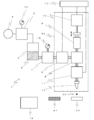
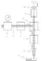
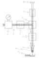
- FIG. 1 shows a view for explaining a discharge device 1 of a dispensing device according to the present embodiment.
- a head portion 34 (a portion surrounded by a dotted line in FIG. 1, which will be described in detail later) constituting the discharge device 1 is movable in the XYZ directions by an XYZ moving mechanism, and the head portion 34 and the dispensing target container 42 are relatively moved. By doing so, the liquid is dispensed.
- the discharge device 1 of the dispensing device includes a nozzle portion having a flow path communicating with a discharge port, a storage portion that supplies a pressure-adjusted liquid pressure transmission medium to the nozzle portion side, and pressure adjustment
- a pressurization unit that supplies the pressurized gas to the storage unit side, a pump mechanism that fluidly communicates with the storage unit and the nozzle unit, and a branch flow path that communicates the nozzle unit, the storage unit, and the pump mechanism.
- a cleaning / drying unit 14 to be configured.
- the nozzle unit includes a nozzle 12 that performs discharge after sucking and temporarily storing the discharge liquid 30.
- the storage unit is a storage container 3 that stores the pressure transmission medium 2, a liquid regulator that is installed between the storage container 3 and the supply valve 6 and adjusts the pressure transmission medium 2 supplied from the storage container 3 to a desired pressure.
- the pressurizing unit is connected to the storage container 3 via a gas pipe and is supplied between the pressurized container 4 and the pressurized gas source 4 for supplying pressurized gas.
- the gas regulator 5 for adjusting the pressurized gas from the gas to a desired pressure is provided.
- the branch portion has a branch block 8 that branches the pressure transmission medium 2 supplied from the storage container 3 in the direction of the pump 9 and the direction of the nozzle 12.
- the pump mechanism includes a pump 9 that is connected to one of the ports of the branch block 8 and sucks and discharges the discharged liquid 30 through the pressure transmission medium 2, and an actuator 10 that operates the pump 9.
- the control unit 13 controls the actuator 10, the supply valve 6, and the discharge valve 11. Details of each device will be described below.
- the storage container 3 of the present embodiment uses a sealed container, and stores the pressure transmission medium 2 therein.
- the pressure transmission medium 2 is made of a liquid, fills the valves (6, 11), the pump 9, the nozzle 12, and the piping connecting them, and plays a role of transmitting the action of pressure to the discharged liquid 30 sucked by the nozzle 12.
- the pressure transmission medium 2 also serves as a cleaning liquid. By discharging the pressure transmission medium 2 from the nozzle 12 together with the discharge liquid 30, the inside of the nozzle 12 (particularly, the portion where the discharge liquid 30 is sucked) is cleaned.
- the pressure transmission medium 2 for example, water or a liquid having a viscosity comparable to that of water is used.
- a pressurized gas source 4 that supplies pressurized gas is connected to the upper part of the storage container 3 via a gas pipe, and a gas regulator that adjusts the pressurized gas to a desired pressure in the middle of the gas pipe. 5 is installed.
- a gas regulator that adjusts the pressurized gas to a desired pressure in the middle of the gas pipe. 5 is installed.
- the gas regulator 5 is preferably provided with a gauge (pressure gauge) 15 for checking the adjustment value.
- the gauge (pressure gauge) 15 may be either an analog type or a digital type.
- the knob attached to the regulator may be turned and adjusted, or may be adjusted by the control unit 13 using an electropneumatic type.
- a dispense controller may be used instead of the gas regulator 5. By using a dispense controller, the pressure value can be easily set and changed.
- a supply valve 6 for starting and stopping the supply of the pressure transmission medium 2 to a pump 9 described later and a nozzle 12 described later is connected to the lower portion of the storage container 3 via a liquid pipe.
- an electromagnetic on-off valve is used as the supply valve 12, and supply of the pressure transmission medium 2 is started and stopped by opening and closing the valve.
- the opening / closing control is performed by the control unit 13 described later.
- a liquid regulator 7 is installed in the middle of the liquid pipe connecting the storage container 3 and the supply valve 6.
- the liquid regulator 7 is preferably provided with a gauge (pressure gauge) 15 for confirming the adjustment value, similarly to the gas regulator 5. Needless to say, the gauge (pressure gauge) 15 may be either an analog type or a digital type.
- the knob attached to the regulator may be turned and adjusted, or may be adjusted by the control unit 13 using an electropneumatic type.
- the pressurized gas supplied from the pressurized gas source 4 is regulated and stabilized by the gas regulator 5, and the stable pressurized gas is supplied.
- the pressure transmission medium 2 on which the pressure acts can be further regulated and stabilized by the liquid regulator 7. Thereby, it is possible to remove the water head difference in the storage container 3, the pressure fluctuation (pulsation) of the pressure source 4, the influence of compressibility, and the like.
- the pressure-regulating / stabilized pressure transmission medium 2 can be supplied to the supply valve 6 related to discharge and the equipment connected to the outlet side thereof.
- the accuracy and stability of discharge can be improved.
- a branch block provided with a flow path for branching the pressure transmission medium 2 supplied from the storage container 3 through the supply valve 6 in the direction of a pump 9 described later and in the direction of a nozzle 12 described later. 8 is connected.
- the flow path in the branch block 8 is formed in a substantially T shape.
- valves (6, 11) and the pump 9 can be directly installed on the block 8, it is possible to reduce the leakage and breakage compared to the case where there is a joint. , Maintenance can be improved.
- a pump 9 that sucks and discharges the discharge liquid 30 through the pressure transmission medium 2.
- a reciprocating positive displacement pump such as a syringe pump or a piston pump (plunger pump) can be used.
- the pump 9 is not used for discharging, but only for sucking and discharging the discharged liquid 30. Further, the pressure transmission medium 2 is not used for pressurization. That is, since the pump 9 is not involved in the operation at the time of discharge, fine control for discharge becomes unnecessary, and the pump 9 does not perform pressurization for discharge. Does not take.
- the pump 9 is provided with an actuator 10 for operating it.
- the actuator 10 for example, a combination of a ball screw and a motor (electric motor) or a direct acting type such as an air cylinder is used corresponding to a reciprocating positive displacement pump.
- the operation of the pump 9 is controlled by controlling the operation of the actuator 10 by the control unit 13 described later.
- the head part 34 to be described later can be configured to be slim and long, and the head parts 34 can be easily arranged side by side. Further, when the head portion 34 is attached to the Z axis, the vertically long head portion is also better.
- a discharge valve 11 that controls discharge by opening and closing the other opening (opening on the lower side in FIG. 1) of the branch block 8 is fluidly communicated.
- a small plunger valve is used as the discharge valve 11.
- other types of valves may be used, but in that case, it is preferable that they can be opened and closed at high speed.
- Discharge is performed by opening and closing the discharge valve 11 at high speed.
- the opening / closing control is performed by the control unit 13 described later.
- a nozzle 12 is fluidly connected to an opening opposite to the opening connected to the branch block 8 of the discharge valve 11. The nozzle 12 is for sucking the discharge liquid 30 from the discharge liquid container 41 and temporarily storing it, and then discharging it to the dispensing target container 42.
- the nozzles 12 are not replaced, and the discharge is performed with one nozzle 12 while cleaning is performed for each dispensing (discharge).
- the tip of the nozzle 12 is preferably coated with a material having water repellency. Examples of the material include fluorine resin and silicon resin. Since the tip of the nozzle 12 is coated with a water-repellent material, the discharge liquid 30 and the cleaning liquid 2 are less likely to remain attached to the outer surface of the nozzle 12 when the discharge liquid 30 is sucked or washed, which is unnecessary. Can prevent dripping and mixing.
- a controller 13 that controls the operation is connected to the actuator 10 that operates the two types of valves (6, 11) and the pump 9 described above.
- the controller 13 controls the opening and closing of the valves (6, 11), the speed and moving distance of the actuator 10, and the like.
- the regulators (5, 7) are electropneumatic, it is also preferable to control them.
- the control unit 13 is sometimes referred to as a “discharge control unit” because it controls discharge.
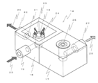
- a cleaning / drying unit 14 that cleans the outer surface of the tip of the nozzle 12 is provided in addition to the above-described devices. Details thereof will be described with reference to FIG.
- the cleaning / drying unit 14 cleans the outer surface of the tip of the nozzle 12 and discharges the discharged liquid 30 remaining after dispensing, and cleans the inner surface of the tip of the nozzle 12, and dries the outer surface of the tip of the nozzle 12 after cleaning. It is divided into a drying unit 17 to be performed.
- the cleaning unit 16 further includes a cleaning unit 18 and a discharge unit 20.
- the cleaning unit 18 includes a spring outlet 18 through which a pipe 19 to which the cleaning liquid 2 is supplied communicates.
- the cleaning liquid 2 stored in the cleaning liquid storage container 36 is supplied to the cleaning unit 16 from the direction of reference numeral 23 in FIG. 2 with the assistance of the pump 38, and the cleaning liquid 2 springs up from the outlet 18 (reference numeral 24).
- cleaning liquid 2 which springs out is a water force like a spring water, and is not the water force which forms a water column at most like a fountain.
- the outer surface of the nozzle 12 can be cleaned by immersing the nozzle 12 in the portion where the cleaning liquid 2 is springing out. Since the cleaning liquid 2 is continuously spouted at the outlet 18, the washed liquid such as the discharged liquid is prevented from flowing back to the cleaning liquid supply side.
- the cleaning liquid 2 is preferably the same liquid as the pressure transmission medium 2 described above.
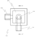
- the discharge unit 20 is a U-shaped groove formed around the cleaning unit (spring outlet) 18. As shown in FIG. 4, the outer wall of the L-shaped channel connecting the spring outlet 18 and the pipe 19 is in contact with the inner bottom of the cleaning unit 16. Unlike the discharge part 20, it is not a groove, although it is one step lower so as not to overflow.
- the cleaning liquid 2 springed out from the spring outlet 18 passes through the groove of the discharge portion 20 and is discharged from a discharge port 21 opened in the unit wall surface (in the direction of arrow 25).
- the discharge unit 20 also discharges the discharged liquid 30 remaining after dispensing.
- the discharged cleaning liquid 2 and the discharge liquid 30 flow into the waste liquid container 37 through the pipe 22 connected to the discharge port 21. At this time, as with the cleaning unit 18, it is preferable to reliably send the waste liquid with the assistance of the pump 39.
- the drying unit 17 has a hole having a size large enough to insert the tip of the nozzle 12 on its upper surface, in other words, a hole 26 whose diameter is larger than the outer diameter of the nozzle 12.
- the pipe 27 is in fluid communication with the vacuum source 44.
- This hole 26 is called an insertion hole.
- the unit 14 for cleaning and drying including the treatment of the waste liquid and the supply of the cleaning liquid is provided in the nozzle movable range, it is possible to easily perform the cleaning from the tip of the nozzle 12 to the drying, and a series of The operation can be automated.
- the inside and outside of the nozzle 12 can be cleaned and dried by the single unit 14, the cleaning and drying operation in the case of discharging a plurality of types of discharge liquids 30 can be automated.
- FIGS. 5 to 11 are diagrams for explaining the dispensing method according to the present embodiment. In these figures, devices between the liquid regulator 5 and the nozzle 12 are shown, and the rest are omitted.
- (1) Supply of pressure transmission medium (FIGS. 5 and 6) As a preparatory stage before discharge, the pressure transmission medium 2 is filled in an empty flow path (substantially T-shaped flow path from the supply valve 6 to the pump 9 and the nozzle 12).
- the piston 29 of the pump 9 is removed from the devices constituting the discharge device 1, the discharge valve 11 is set in the “closed” state, and the supply valve 6 is set in the “closed” state.
- the storage container 3 containing the pressure transmission medium 2 is connected to the inlet side of the supply valve 6, and the pressurized gas source 4 is connected to the storage container 3.
- the gas regulator 5 is adjusted to zero.
- the liquid regulator 7 is adjusted to a discharge pressure described later.
- the gas regulator 5 is adjusted to a predetermined pressure
- the pressure transmission medium 2 is supplied to the inlet of the supply valve 6 by the action of the pressurized gas.
- the set pressure of the gas regulator 5 may be set slightly higher than the set pressure of the liquid regulator 7 in consideration of the loss in the liquid regulator 7 installed on the downstream side.
- the tip of the nozzle 12 is moved onto the discharge unit 20 of the cleaning unit 16 of the cleaning / drying unit 14 by the XYZ moving mechanism.
- the pressure transmission medium 2 is supplied to the tip (outlet side) of the supply valve 6 by the action of the pressurized gas. Then, as shown in FIG. 5, a part of the pressure transmission medium 2 also flows in the direction of the nozzle 12, but first flows in the direction of the pump 9. When the pressure transmission medium 2 reaches the upper end of the pump 9 or overflows, the supply valve 6 is closed. The piston 29 that has been removed is inserted, and the piston end is fixed to the actuator. When both the discharge valve 11 and the supply valve 6 are in the “open” state, as shown in FIG. 6, the pressure transmission medium 2 flows toward the nozzle 12 and finally flows out from the tip of the nozzle 12.
- the pressure transmission medium 2 and the discharge liquid 30 are mixed with each other.
- an amount of about 10% of the amount of one drop is sucked.
- the tip of the nozzle 12 is immersed in the discharge liquid 30, and the piston 29 of the pump 9 is retracted to suck the discharge liquid 30.
- the suction amount is adjusted by the retraction amount of the piston 29 of the pump 9.
- the amount of the discharge liquid 30 to be sucked is preferably slightly larger than the total amount to be dispensed.
- the tip portion of the nozzle 12 has a length that can store an amount to be dispensed at a time (for example, the total amount when discharging to all the concave portions of a plate integrally provided with a plurality of concave portions). It is preferable to do.
- the diameter of the nozzle 12 is appropriately selected according to the amount of one droplet to be discharged. For example, in the present embodiment, a tapered conical nozzle having an inner diameter of about 0.1 [mm] and a tip portion having a length of 5 to 10 [mm] is used.
- the pressurized gas supplied from the pressurized gas source 4 is regulated and stabilized by the gas regulator 5, and the stable pressurized gas is supplied. Since the pressure transmission medium 2 on which the pressure acts is further regulated and stabilized by the liquid regulator 7, the effects of the water head difference in the storage container 3, pressure fluctuation (pulsation) of the pressure source 4, and compressibility are eliminated. can do.
- the discharge liquid 30 in the flow path from the outlet side of the discharge valve 11 to the nozzle 12 has not been pressurized yet. However, as described above, the distance from the discharge valve 11 to the nozzle 12 is configured to be as short as possible, so that the pressure at the time of discharge is transmitted promptly.
- the set value of the pressure of the liquid regulator 7 is obtained in advance by an experiment or the like depending on the amount of one drop or whether or not to fly. However, it is necessary to consider it together with the valve opening / closing time described later (see (4) below for specific numerical examples).
- Discharge of discharged liquid (FIG. 9) Discharge is started when pressurization of the pressure transmission medium is completed.
- the head part 34 described later is moved by the XYZ moving mechanism so that the tip of the nozzle 12 is positioned above the target container 42 for dispensing.
- the discharge valve 11 is in the “open” state, pressure is transmitted to the discharge liquid 30 in the nozzle 12 on the outlet side of the discharge valve 11 via the pressure transmission medium 2, and the discharge liquid 30 starts to flow out of the nozzle 12.
- the discharge valve 11 is in the “closed” state after a predetermined time has elapsed, the pressure transmission is stopped and the discharge of the discharge liquid 30 from the nozzle 12 is stopped.
- the discharge liquid 30 is made to drop and fly from the nozzle 12 to be dispensed target containers. 42 can be discharged to a dispensing position. Further, if the discharge method is based on the action of pressure from the pressurized gas source 4, flight discharge in which the amount of one drop, which is difficult with the discharge method based on the action of the piston 29, is also possible. When there are a plurality of dispensing positions in the dispensing target container 42, the movement of the nozzle 12 and the opening and closing of the discharge valve 11 are repeated.
- the set value of the time is obtained in advance by an experiment or the like depending on the amount of one drop and whether or not to fly, like the pressure value.
- the discharge amount is mainly adjusted by the valve opening / closing time.
- the pressure setting is rarely changed once determined. This is because time is more responsive than pressure.
- the time and the discharge amount are in a substantially proportional relationship, the setting can be adjusted relatively easily.
- a pressure of 30 [kPa] (kilopascal) is applied to a discharge liquid having a viscosity of about 1 [mPa ⁇ s] (millipascal second), and a 1 [msec] (millisecond) discharge valve is set.
- Discharging / cleaning / drying (FIG. 10)
- the discharged liquid 30 remaining in the nozzle 12 is discharged, and at the same time, the inside and outside of the nozzle 12 are cleaned.
- the discharge valve 11 is set to the “closed” state, and the head unit 34 (to be described later) is moved by the XYZ moving mechanism so that the tip of the nozzle 12 is positioned at the discharge unit 20 of the cleaning unit 16 of the cleaning / drying unit 14. Subsequently, the discharge valve 11 is opened and the discharge liquid 30 remaining in the nozzle 12 is discharged.
- the discharge liquid 30 in the nozzle 12 is discharged together with the pressure transmission medium 2 while being pushed out by the pressure transmission medium 2.
- the pressure transmission medium 2 that also serves as the cleaning liquid 2 can clean the inner surface of the nozzle 12 tip.
- the nozzle 12 is preferably positioned below the upper end of the wall surface of the discharge unit 20 of the cleaning unit 14 by the XYZ moving mechanism so as not to scatter.
- the discharge valve 11 is set to the “closed” state.
- the tip of the nozzle 12 is moved by the XYZ moving mechanism to the cleaning unit 18 of the cleaning unit 16 of the cleaning / drying unit 14, and the outer surface of the nozzle 12 is cleaned with the cleaning liquid 2 that comes from the cleaning unit 18.
- the nozzle 12 When cleaning the nozzle 12, the nozzle 12 is not inserted into the spring outlet 18, but may be immersed in a portion that is springing over the spring outlet 18. When it is desired to change the region of the nozzle 12 to be cleaned, it may be changed by adjusting the water flow from which the cleaning liquid 2 is swelled.
- the cleaning liquid 2 is preferably the same as the pressure transmission medium 2. This is because if the cleaning liquid 2 and the pressure transmission medium 2 are different, the cleaning liquid 2 and the pressure transmission medium 2 are mixed in the portion immersed in the cleaning liquid 2 at the tip of the nozzle 12.
- the tip of the nozzle 12 is moved onto the drying unit 17 of the cleaning / drying unit 14 by the XYZ moving mechanism, and the tip of the nozzle 12 is inserted into the insertion hole 26. Then, the tip of the nozzle 12 is dried by sucking the air around the nozzle 12 and sucking the excess liquid (mainly the cleaning liquid 2) adhering to the outer surface of the nozzle 12. In this way, the cleaning liquid or the like is not adhered to the outer surface of the tip of the nozzle 12 but is kept dry, so that the next time the suction of the discharge liquid 30 is performed, the mixing of the cleaning liquid 2 and the discharge liquid 30 is ensured. It becomes possible to prevent.
- the pressure transmission medium 2 corresponding to the advancement of the piston 29 is discharged from the nozzle 12 to the discharge unit 20 of the cleaning unit 16.
- the pressurized gas supplied from the pressurized gas source 4 is used as the gas regulator. Since the pressure transmission medium 2 that is regulated and stabilized at 5 and the stable pressurized gas acts is further regulated and stabilized by the liquid regulator 7, the water head difference in the storage container 3 and the pressure source 4 Pressure fluctuation (pulsation), compressive effects, etc. can be removed. Further, by providing the liquid regulator 7 in front of the inlet of the supply valve 6, the pressure-regulating / stabilized pressure transmission medium 2 can be supplied to the supply valve 6 related to discharge and the equipment connected to the outlet side thereof. In addition, the accuracy and stability of discharge can be improved.
- the unit 14 for cleaning and drying including waste liquid processing and cleaning liquid supply is provided in the nozzle movable range, the nozzle 12 tip can be cleaned and dried quickly and easily. The operation can be automated. Then, the cleaning liquid or the like is not left attached to the outer surface of the tip of the nozzle 12, but when the discharge liquid is sucked next time, it is possible to reliably prevent the mixing of the cleaning liquid and the discharge liquid. Become.
- the inside and outside of the nozzle 12 can be cleaned and dried by the single unit 14, the cleaning and drying operation in the case of discharging a plurality of types of discharge liquids 30 can be automated.
- the discharge liquid 30 is made to drop and fly from the nozzle 12 to the target. It is possible to discharge.
- the discharge method is based on the action of pressure, it is possible to perform flight discharge in which the amount of one drop, which is difficult with the discharge method based on the action of the piston 29, is very small.
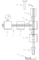
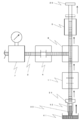
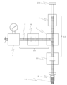
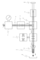
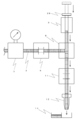
- FIG. 12 is a diagram illustrating the overall configuration of the dispensing apparatus according to the present embodiment.
- the dispensing device 33 according to the present embodiment includes a discharge device 1 that performs suction and discharge of the discharge liquid 30 and cleaning of the nozzle 12, a work table 40 on which the dispensing target container 42 and the discharge liquid container 41 are placed.
- An XYZ moving mechanism that relatively moves the nozzle 12 and the work table 40 is a main element. Details of each will be described below.
- Discharge device The basic configuration is the same as that shown in FIG. 1, but the installation location differs for each device.
- the nozzle 12, the branch block 8, the pump 9, the actuator 10, and the supply valve 6 are integrally attached to one base and installed in a Z moving mechanism 47 described later.
- a group attached to the base is referred to as a head portion 34 (portion surrounded by a dotted line in FIG. 1).
- the head portion 34 is covered with a cover except for the nozzle 12 portion.
- the liquid regulator 7, the storage container 3, and the gas regulator 5 are installed on the side of the casing of the dispensing device 33.
- the regulators (5, 7) and the storage container 3 are installed separately from the head part 34.
- the storage container 3 may be an airtight container as described in the embodiment, regardless of the material, shape, and the like.
- a syringe used in a tank, a bottle, or an air dispenser may be used.
- an analog type is drawn as the gauge (pressure gauge) 15 attached to each regulator (5, 7), but it goes without saying that a digital type may be used.
- a dispense controller may be used instead of the gas regulator.
- the supply valve 6 of the head unit 34 and the liquid regulator 7 are connected by a pipe 35 illustrated by a dotted line.
- the pipe 35 is preferably made of a flexible material in consideration of the movement of the head portion 34.
- the pressurized gas source 4 is provided separately from the dispensing device 33 and is connected to the gas regulator 5 via a pipe.
- the illustration is simplified. As a specific example, it is disclosed to use a general compressor or to receive supply directly from factory equipment.
- the cleaning / drying unit 14 is installed at a position that does not interfere with the table movement on the upper surface of the casing beside the work table 40.
- the cleaning / drying unit 14 has the same configuration as in FIG. 2, and includes a cleaning unit 16 and a drying unit 17.
- the cleaning liquid container 36, the waste liquid container 37, the cleaning liquid pump 38, and the waste liquid pump 39 attached to the cleaning unit 16 are arranged on the side surface of the main body of the dispensing device 33 on the side of the casing opposite to the regulator (5, 7). Installed in an adjacent position.
- the cleaning unit 16 is connected to the cleaning liquid container 36 and the waste liquid container 37 by piping through the cleaning liquid pump 38 and the waste liquid pump 39, respectively.
- the discharge controller 13 is installed on the side surface of the dispensing device 33 housing on the cleaning / drying unit 14 side.
- the discharge controller 13 controls the operation of the actuator 10 that operates the pump 9 and the two types of valves (6, 11).
- the discharge controller 13 also controls operations of the cleaning liquid pump 38 and the waste liquid pump 39 provided in the above-described cleaning unit 16.
- the worktable 40 has a discharge liquid container 41 and a dispensing target container 42 placed on the upper surface thereof.
- these containers (41, 42) have a plate shape in which a plurality of recesses (wells) are integrally provided, and a plurality of types of samples / reagents and specimens are contained in the plurality of recesses. Then, the sample / reagent in the recess is aspirated or the sample / reagent is discharged toward the recess to perform analysis and inspection.
- a method of fixing each of the containers (41, 42) a method of making a plurality of holes leading from the inside of the table 40 to the upper surface and sucking and fixing the air by sucking air from the holes, and sandwiching the container with a fixing member
- a method of fixing the container by fixing the member to the table 40 with fixing means such as a screw can be used.
- suction fixation it is necessary to connect a vacuum source 44 separately.
- Adsorption fixation may be employed if handling is easy.
- a vacuum control unit 43 for controlling the negative pressure gas used for suction in the drying unit 17 and suction fixing in the work table 40 is provided in the housing of the dispensing device 33. It is installed on the side of the body.
- the vacuum source 44 is provided separately from the dispensing device 33 and is connected to the vacuum control unit 43 by piping.
- Each of the containers (41, 42) can be placed at a position that does not interfere with the movement of the work table 40 as in the cleaning / drying unit 14, but if the work table 40 has sufficient space, it is placed together. It is better to end up. This is because the moving distance between the discharge liquid container 41 and the dispensing target container 42 is shortened, and the working time is shortened accordingly.
- the XYZ moving mechanism is installed on a gate-shaped frame, and moves the Z moving mechanism 47 on which the head unit 34 is installed in the direction of reference numeral 48, and the X moving mechanism 45 It is installed on the Y movement mechanism 46 for moving the work table 40 in the direction of reference numeral 49 and the Z movement mechanism 47 for moving the head unit 34 in the direction of reference numeral 50.
- a control unit (not shown) for the moving mechanism is provided in the housing under the Y moving mechanism 46.
- the control unit also controls the XYZ movement operation and transmits an operation signal to the discharge control unit 13 that controls the discharge device 1. Further, it has a storage device (not shown) for storing a coating program in which the XYZ movement operation, the discharge operation timing, and the like are routineized.
- the ejection liquid of this example is a reagent for detecting blood and urine, and antigens and antibodies from them, and 96 (8 ⁇ 12) wells are dispensed in a volume of 20 to 30 nL (nanoliter). Dispense into the formed microplate.
- the discharge liquid container 41 and the dispensing target container 42 are placed on the work table 40 and fixed.
- the storage container 3 containing the pressure transmission medium 2, the cleaning liquid container 36, and the waste liquid container 37 are installed, and the piping is connected to the pumps (38, 39), the head unit 34, and the like.
- the supply of the pressure transmission medium 2 and the suction and pressurization of the discharge liquid 30 are performed in accordance with the procedure of FIGS. 5 to 11 shown in the embodiment.
- the head part 34 is moved with respect to the dispensing target container 42, and the discharge liquid 30 is discharged (refer FIG. 9).
- the head unit 34 is not stopped every time the recesses are positioned above the recesses, but if the discharge is performed while moving, the working time can be shortened. it can.
- the discharge liquid 30 that has been dispensed is discharged, washed, and dried in accordance with the discharge / cleaning / drying procedure described in the embodiment.
- the discharge liquid 30 is sucked and discharged (see FIGS. 10 and 11). If another discharge liquid 30 is to be discharged, the above-described discharge / cleaning / drying / suction / discharge steps are repeated.
- finishing the work it is preferable to finish the whole work after finishing the discharging, washing and drying processes.
- the dispensing device 33 of Example 1 can achieve a high accuracy of about 1 to 0.5% as the dispensing accuracy as a variation in the discharge amount.
Abstract
Description
吐出部には様々なタイプがあるが、試料・試薬が供給される方向で大まかに二つに分けることができる。一つは、試料・試薬の供給が排出口(ノズル)の反対端からされるタイプ、もう一つは、試料・試薬の供給が排出口(ノズル)と同一端からされるタイプ、すなわち、排出口(ノズル)から試料・試薬を吸引し、排出口(ノズル)から試料・試薬を吐出するタイプである。特に、試料・試薬が高価或いは稀少であって少量しか用意できない場合にポンプや配管等を動作に必要な試料・試薬で満たすことができないとき、または吐出する試料・試薬の種類が多くあってポンプや配管等に満たした動作に必要な試料・試薬の除去や洗浄に手間がかかるとき等には、試料・試薬の供給が排出口(ノズル)と同一端からされるタイプ、すなわち、排出口(ノズル)から試料・試薬を吸引し、排出口(ノズル)から試料・試薬を吐出するタイプが用いられることが多い。
このようなタイプの分注装置では、微量で正確な吐出を行うため、排出口(ノズル)から吐出される試料・試薬を目標に到達する前に排出口(ノズル)先端から離間させ、飛翔させながら目標に向かうように吐出させることが多い。本明細書内では、このような吐出を「飛翔吐出」または「非接触吐出」と呼ぶこととする。 In general, a dispensing device is composed of a pump for extracting a sample / reagent from a container for storing a liquid sample or liquid reagent, a nozzle for discharging the extracted sample / reagent, a discharge unit composed of a pipe connecting them, a nozzle, It is mainly composed of a drive unit that is a mechanism for relatively moving a container to be dispensed, and a control unit that controls the operation of devices such as a pump and a drive unit. Of particular importance in the above configuration is the discharge section that directly handles liquid samples and liquid reagents.
There are various types of discharge units, but they can be roughly divided into two in the direction in which the sample / reagent is supplied. One is a type in which the sample / reagent is supplied from the opposite end of the discharge port (nozzle), and the other is a type in which the sample / reagent is supplied from the same end as the discharge port (nozzle). In this type, the sample / reagent is sucked from the outlet (nozzle) and the sample / reagent is discharged from the outlet (nozzle). In particular, when the sample / reagent is expensive or rare and only a small amount is available, the pump or piping cannot be filled with the sample / reagent necessary for operation, or there are many types of sample / reagent to be discharged. When it takes time to remove or clean the sample / reagent necessary for the operation filled in the pipe, etc., the sample / reagent is supplied from the same end as the discharge port (nozzle), that is, the discharge port ( In many cases, a sample / reagent is sucked from a nozzle and a sample / reagent is discharged from a discharge port (nozzle).
In such a type of dispensing device, the sample / reagent discharged from the discharge port (nozzle) is separated from the tip of the discharge port (nozzle) before it reaches the target in order to perform accurate discharge in a small amount. In many cases, however, the ink is discharged toward the target. In the present specification, such discharge is referred to as “flying discharge” or “non-contact discharge”.
他方で、特許文献3に記載される分注装置のように液状の伝達媒質(システムリキッド)をポンプで加圧する構成の場合、センサなどの機器を設け、液体の圧力変化をフィードバックする制御が必要であり(例えば、同文献[0030]参照)、圧力を一定に保つ仕組みが複雑になってしまうという問題があった。また、液体を連続吐出する間は常にポンプを動作させた状態であるので、ポンプへの負荷が大きく、ポンプの寿命が短命になるという問題もある。
さらに、特許文献4に記載される分注装置のように液状の伝達媒体を気体で直接加圧する構成の場合、気体加圧の作用が直接試料に伝わってしまうことの問題がある。すなわち、バッファタンク内の液状の伝達媒体が減ることによる水頭差の影響を受けてしまうこと、気体の圧縮性の影響を受けてしまうこと、気体加圧源の圧力変動(脈動)の影響を受けてしまうこと、などの問題が起きていた。そして、これらの影響を受けると、水頭差および気体の圧縮性に起因する応答性の悪さや、気体加圧源の圧力変動(脈動)に起因する安定性の悪さを有する圧力が付与された伝達媒体がバルブに供給されてしまうため、分注精度が損なわれるという問題があった。 A structure in which the amount of one drop is a very small amount (for example, several tens of μL or less), in particular, a very small amount (for example, a few tens of nL or less) for “flying discharge” or “non-contact discharge”. In this case, since the moving distance is short, sufficient acceleration cannot be performed and a force (pressure) sufficient to cause the droplet to fly cannot be applied.
On the other hand, in the case of a configuration in which a liquid transmission medium (system liquid) is pressurized with a pump as in the dispensing device described in
Furthermore, in the case of a configuration in which a liquid transmission medium is directly pressurized with gas as in the dispensing apparatus described in
第2の発明は、第1の発明において、前記加圧部が気体用レギュレータを備え、前記貯留部が液体用レギュレータを備えることを特徴とする。
第3の発明は、第1の発明において、前記加圧部がディスペンスコントローラを備えることを特徴とする。
第4の発明は、第1ないし3のいずれかの発明において、前記分岐部をブロック状部材で構成し、当該ブロック状部材、前記供給バルブ、前記ポンプ機構、前記吐出バルブおよび前記ノズル部を一つのベースに対して一体的に配設して構成したヘッド部を備えることを特徴とする。
第5の発明は、第1ないし4のいずれかの発明に係る吐出装置と、分注目標容器と吐出液体容器とを載置するワークテーブルと、ノズル部とワークテーブルとを相対的に移動させるXYZ移動機構と、を備えることを特徴とする液体分注装置である。
第6の発明は、第5の発明において、前記ノズル部から吐出された液体を受ける排出部および洗浄液湧出口を備える洗浄ユニットと、前記ノズル部の先端に吸引力を作用させて乾燥させる乾燥ユニットと、をさらに備えることを特徴とする。
第7の発明は、第5または6の発明において、卓上型であることを特徴とする。 In the first invention, an amount of discharged liquid to be discharged a plurality of times is sucked through a gap from a discharge port of a nozzle portion filled with a pressure transmission medium in a flow path, and a small amount of liquid droplets are continuously ejected and discharged. A nozzle unit having a flow channel communicating with a discharge port, a storage unit that supplies a regulated liquid pressure transmission medium to the nozzle unit side, and a pressurized pressurized gas that is a storage unit side A pressurization unit for supplying to the pump, a pump mechanism in fluid communication with the storage unit and the nozzle unit, a branch unit provided with a branch channel for communicating with the nozzle unit, the storage unit and the pump mechanism, and the branch unit and the nozzle A discharge valve that communicates or shuts off the part, a supply valve that communicates or shuts off the branch part and the storage part, and a control part, and the control part closes the discharge valve and opens the supply valve. , Supply pressurized gas regulated by the pressurization unit to the storage unit side A liquid pressure transmission medium regulated by the reservoir is supplied to the supply valve side, and then a small amount of droplets are continuously ejected and ejected by opening and closing the discharge valve at a predetermined timing. It is a discharge device.
According to a second aspect, in the first aspect, the pressurizing unit includes a gas regulator, and the storage unit includes a liquid regulator.
According to a third aspect, in the first aspect, the pressurizing unit includes a dispense controller.
According to a fourth invention, in any one of the first to third inventions, the branch portion is configured by a block-shaped member, and the block-shaped member, the supply valve, the pump mechanism, the discharge valve, and the nozzle portion are integrated. It is characterized by comprising a head portion that is integrally arranged with respect to one base.
A fifth invention relatively moves the discharge device according to any one of the first to fourth inventions, the work table on which the dispensing target container and the discharge liquid container are placed, the nozzle portion, and the work table. And an XYZ moving mechanism.
According to a sixth invention, in the fifth invention, a cleaning unit comprising a discharge part for receiving the liquid discharged from the nozzle part and a cleaning liquid outlet, and a drying unit for drying by applying a suction force to the tip of the nozzle part And further comprising.
The seventh invention is characterized in that, in the fifth or sixth invention, it is a desktop type.
第9の発明は、吐出口と連通する流路を有するノズル部と、調圧された液状の圧力伝達媒質をノズル部側に供給する貯留部と、調圧された加圧気体を貯留部側に供給する加圧部と、貯留部およびノズル部と流体的に連通されるポンプ機構と、ノズル部、貯留部およびポンプ機構を連通する分岐流路が設けられた分岐部と、分岐部とノズル部とを連通または遮断する吐出バルブと、分岐部と貯留部とを連通または遮断する供給バルブと、分注目標容器と吐出液体容器とを載置するワークテーブルと、ノズル部とワークテーブルとを相対的に移動させるXYZ移動機構と、前記ノズル部から吐出された液体を受ける排出部および洗浄液湧出口を備える洗浄ユニットと、前記ノズル部の先端に吸引力を作用させて乾燥させる乾燥ユニットと、を備えた液体分注装置を用いて複数種類の吐出液体を連続的に吐出する液体分注方法であって、第1の吐出液体について、流路内に圧力伝達媒質が充填されたノズル部の吐出口から空隙を介して複数回吐出する分量の吐出液体を吸引する第1の工程、吐出バルブを閉じ、供給バルブを開いた状態で、加圧部により調圧された加圧気体を貯留部側に供給するとともに貯留部により調圧された液状の圧力伝達媒質を供給バルブ側に供給する第2の工程、ノズル部とワークテーブルとを相対的に移動しながら、吐出バルブを所定のタイミングで開閉することにより微量の液滴を連続的に飛翔吐出する第3の工程、ノズル部を洗浄ユニットへ移動し、ノズル部内に残存する吐出液体を排出し、ノズル部の先端を洗浄する第4の工程、ノズル部を乾燥ユニットへ移動し、ノズル部の先端を乾燥する第5の工程、ノズル部を洗浄ユニットへ移動し、供給バルブを閉じ、吐出バルブを開いた状態で、圧力伝達媒質を吐出口から排出する第6の工程、第2の吐出液体について、第1ないし第3の工程を実行する第7の工程、を含んでなる液体分注方法である。
第10の発明は、第8または9の発明において、一回に吐出される液滴の分量が1μL以下であることを特徴とする。
第11の発明は、第10の発明において、一回に吐出される液滴の分量が数十nL以下であることを特徴とする。 According to an eighth aspect of the present invention, there is provided a nozzle portion having a flow path communicating with the discharge port, a storage portion for supplying a pressure-adjusted liquid pressure transmission medium to the nozzle portion side, and a pressure-controlled pressurized gas on the storage portion side A pressurization unit for supplying to the pump, a pump mechanism in fluid communication with the storage unit and the nozzle unit, a branch unit provided with a branch channel for communicating with the nozzle unit, the storage unit and the pump mechanism, and the branch unit and the nozzle A discharge valve that communicates or shuts off the part, a supply valve that communicates or shuts off the branch part and the storage part, a work table on which the dispensing target container and the discharge liquid container are placed, and a nozzle part and a work table. A liquid dispensing method for continuously ejecting discharged liquid using a liquid dispensing apparatus having an XYZ moving mechanism for relatively moving, wherein a nozzle portion in which a pressure transmission medium is filled in a flow path For multiple discharges from the discharge port through the gap In the first step of sucking the discharged liquid, the pressurized gas conditioned by the pressurizing unit was supplied to the storage unit side with the discharge valve closed and the supply valve opened, and the pressure was adjusted by the storage unit Second step of supplying the liquid pressure transmission medium to the supply valve side, while moving the nozzle part and the work table relative to each other, by opening and closing the discharge valve at a predetermined timing, a small amount of liquid droplets are continuously formed. A liquid dispensing method comprising a third step of flying and discharging.
According to a ninth aspect of the present invention, there is provided a nozzle portion having a flow path communicating with the discharge port, a storage portion for supplying a pressure-adjusted liquid pressure transmission medium to the nozzle portion side, and a pressure-controlled pressurized gas on the storage portion side A pressurization unit for supplying to the pump, a pump mechanism in fluid communication with the storage unit and the nozzle unit, a branch unit provided with a branch channel for communicating with the nozzle unit, the storage unit and the pump mechanism, and the branch unit and the nozzle A discharge valve that communicates or shuts off the part, a supply valve that communicates or shuts off the branch part and the storage part, a work table on which the dispensing target container and the discharge liquid container are placed, and a nozzle part and a work table. An XYZ moving mechanism that moves relatively; a cleaning unit that includes a discharge unit that receives the liquid discharged from the nozzle unit and a cleaning liquid outlet; and a drying unit that applies suction to the tip of the nozzle unit to dry it. With A liquid dispensing method for continuously discharging a plurality of types of discharged liquid using a liquid dispensing apparatus, wherein the first discharged liquid is discharged from a discharge port of a nozzle portion in which a flow path is filled with a pressure transmission medium. The first step of sucking the amount of discharged liquid to be discharged multiple times through the gap, supplying the pressurized gas conditioned by the pressure unit to the storage unit side with the discharge valve closed and the supply valve opened And a second step of supplying the liquid pressure transmission medium regulated by the reservoir to the supply valve side, opening and closing the discharge valve at a predetermined timing while relatively moving the nozzle part and the work table. A third step of continuously flying and discharging a small amount of liquid droplets, a fourth step of moving the nozzle portion to the cleaning unit, discharging the discharge liquid remaining in the nozzle portion, and cleaning the tip of the nozzle portion, the nozzle Part drying unit A fifth step of moving and drying the tip of the nozzle portion; a sixth step of moving the nozzle portion to the cleaning unit, closing the supply valve and opening the discharge valve, and discharging the pressure transmission medium from the discharge port; A liquid dispensing method including a seventh step of executing the first to third steps for the second discharge liquid.
A tenth invention is characterized in that, in the eighth or ninth invention, the amount of droplets ejected at one time is 1 μL or less.
An eleventh invention is characterized in that, in the tenth invention, the amount of droplets ejected at one time is several tens of nL or less.
また、ポンプで液体を吐出するための加圧を行わないのでポンプに負荷がかからず、各機器(特にポンプやアクチュエータ)の長寿命化につながる。
さらに、気体の圧力と液体の圧力を別々に調節するため、気体加圧の作用が直接試料・試薬に伝わることがないので、圧力の印加に対する応答性や安定性がよくなり、高精度な吐出を実現することができる。 According to the present invention, there is no need to provide a pressure sensor or the like and there is no need to feed back the measured value, so that the configuration for keeping the pressure constant is simple and the control is simple.
In addition, since pressurization for discharging the liquid is not performed by the pump, the load is not applied to the pump, leading to a long life of each device (particularly, pump and actuator).
In addition, since the gas pressure and liquid pressure are adjusted separately, the action of gas pressurization is not directly transmitted to the sample / reagent, which improves responsiveness and stability against pressure application and enables high-precision discharge. Can be realized.
また、廃液の処理や洗浄液の供給も含めた洗浄と乾燥を行うユニットをノズル可動範囲に設けた構成においては、ノズル先端の洗浄から乾燥までの一連の作業を自動化することができる。くわえて、複数種の吐出液体の分注作業も自動化することができる。 In addition to cleaning the inside and outside of the nozzle with the cleaning liquid, the nozzle tip is dried after cleaning, so that contamination can be reliably prevented.
Further, in a configuration in which a unit for performing cleaning and drying including waste liquid processing and cleaning liquid supply is provided in the nozzle movable range, a series of operations from cleaning the nozzle tip to drying can be automated. In addition, the dispensing operation of a plurality of types of discharged liquids can be automated.
[構成]
図1に本実施の形態に係る分注装置の吐出装置1を説明する図を示す。吐出装置1を構成するヘッド部34(図1中点線で囲った部分。詳細は後述)は、XYZ移動機構によりXYZ方向に移動自在とされ、ヘッド部34と分注目標容器42とを相対移動することにより液体の分注が行われる。
本実施の形態に係る分注装置の吐出装置1は、吐出口と連通する流路を有するノズル部と、調圧された液状の圧力伝達媒質をノズル部側に供給する貯留部と、調圧された加圧気体を貯留部側に供給する加圧部と、貯留部およびノズル部と流体的に連通されるポンプ機構と、ノズル部、貯留部およびポンプ機構を連通する分岐流路が設けられた分岐部と、分岐部とノズル部とを連通または遮断する吐出バルブと、分岐部と貯留部とを連通または遮断する供給バルブ6と、制御部13と、ノズル12先端外面の洗浄及び乾燥を行う洗浄乾燥ユニット14と、を備えて構成される。
ノズル部は、吐出液体30を吸引して一時的に溜め込んだあと吐出を行うノズル12を有する。
貯留部は、圧力伝達媒質2を貯留する貯留容器3、貯留容器3と供給バルブ6との間に設置されて貯留容器3から供給される圧力伝達媒質2を所望の圧力に調整する液体用レギュレータ7を有する。
加圧部は、貯留容器3に気体配管を介して接続されて加圧気体を供給する加圧気体源4、貯留容器3と加圧気体源4との間に設置されて加圧気体源4からの加圧気体を所望の圧力に調整する気体用レギュレータ5を有する。
分岐部は、貯留容器3から供給される圧力伝達媒質2をポンプ9方向とノズル12方向へ分岐させる分岐ブロック8を有する。
ポンプ機構は、分岐ブロック8の口の一つに接続されて圧力伝達媒質2を介して吐出液体30を吸引および排出を行うポンプ9、ポンプ9を作動させるアクチュエータ10を有する。
制御部13は、アクチュエータ10や供給バルブ6、吐出バルブ11を制御する。以下、各機器の詳細について説明する。 Below, an example of the form for implementing this invention is demonstrated. Hereinafter, the liquid sample and the liquid reagent are collectively referred to as a discharge liquid.
[Constitution]
FIG. 1 shows a view for explaining a
The
The nozzle unit includes a
The storage unit is a
The pressurizing unit is connected to the
The branch portion has a
The pump mechanism includes a
The
貯留容器3の上部には、加圧気体を供給する加圧気体源4が気体配管を介して接続されており、その気体配管の途中には加圧気体を所望の圧力に調整する気体用レギュレータ5が設置されている。気体用レギュレータ5としては、周知の気体用レギュレータを用いることができる。なお、気体用レギュレータ5には、調整値確認のためゲージ(圧力計)15が付属していることが好ましい。ゲージ(圧力計)15は、アナログ式でもデジタル式でもどちらも用いることができるのは言うまでもない。また、調圧に際しては、レギュレータに付属のツマミを回して調節してもよいし、電空式を用いて制御部13にて調節するようにしてもよい。ここで、気体用レギュレータ5の代わりにディスペンスコントローラを用いてもよい。ディスペンスコントローラを用いることで、圧力値の設定・変更などが容易に行えるようになる。 The
A
貯留容器3と供給バルブ6とを接続する液体配管の途中には液体用レギュレータ7が設置されている。液体用レギュレータ7としては、周知の液体用レギュレータを用いることができる。なお、液体用レギュレータ7には気体用レギュレータ5と同様に、調整値確認のためゲージ(圧力計)15が付属していることが好ましい。ゲージ(圧力計)15は、アナログ式でもデジタル式でもどちらも用いることができるのは言うまでもない。また、調圧に際しては、レギュレータに付属のツマミを回して調節してもよいし、電空式を用いて制御部13にて調節するようにしてもよい。この液体用レギュレータ7と上述の気体用レギュレータ5を二段階で設けることで、加圧気体源4から供給される加圧気体を気体用レギュレータ5で調圧・安定させ、その安定した加圧気体が作用する圧力伝達媒質2を液体用レギュレータ7でさらに調圧・安定させることができる。これにより、貯留容器3での水頭差や加圧源4の圧力変動(脈動)、圧縮性の影響などを除去することができる。また、液体用レギュレータ7を供給バルブ6の入口手前に設けることで、調圧・安定させた圧力伝達媒質2を吐出に関係する供給バルブ6およびその出口側に接続された機器へ供給することができ、吐出の精度や安定性を向上させることができる。 A
A
分岐ブロック8の開口の一つ(図1の上方側の開口)には、圧力伝達媒質2を介して吐出液体30を吸引および排出を行うポンプ9が流体的に連通されている。ポンプ9としては、例えばシリンジポンプ、ピストンポンプ(プランジャポンプ)などの往復式容積型ポンプを用いることができる。本実施の形態においては、ポンプ9は吐出には使用せず、吐出液体30の吸引および排出のみに用いる。また、圧力伝達媒質2の加圧にも使用しない。すなわち、ポンプ9が吐出時の動作には関与することがないので、吐出のための細かな制御が不要となり、ポンプ9では吐出のための加圧を行わないので、加圧による負荷がポンプ9にはかからない。
上記ポンプ9にはこれを動作させるアクチュエータ10が設けられている。アクチュエータ10としては、往復式容積型ポンプに対応して、例えばボールネジとモータ(電動機)の組み合わせ、或いはエアシリンダなど直動式のものを用いる。なお、後述する制御部13にてアクチュエータ10の動作を制御することによりポンプ9の動作を制御する。
卓上型の分注装置を構成する際には、ポンプ9およびアクチュエータ10をノズル12の上方に配置することが好ましい。このような配置とすることにより、後述するヘッド部34を縦長にスリムに構成でき、ヘッド部34を横並びに配置することも容易になるからである。また、ヘッド部34をZ軸に取り付けたときの見栄えも縦長のヘッド部の方がよい。 On the outlet side of the
One of the openings of the branch block 8 (the upper opening in FIG. 1) is fluidly connected to a
The
When configuring a desktop dispenser, it is preferable to dispose the
吐出バルブ11の分岐ブロック8と接続される開口と反対側の開口には、ノズル12が流体的に連通されている。ノズル12は、吐出液体30を吐出液体容器41から吸引して一時的に溜め込んだあと、分注目標容器42へ吐出を行うためのものである。本実施の形態では、異なる種類の吐出液体を分注する際にもノズル12を交換することなく、分注(吐出)の都度洗浄を行いながら一つのノズル12で吐出を行う。ノズル12先端部は撥水性を有する材料でコーティングされていることが好ましい。材料としては、フッ素系樹脂やシリコン系樹脂などが例示される。ノズル12先端部が撥水性を有する材料でコーティングされていることで、吐出液体30の吸引や洗浄の際、ノズル12外面に吐出液体30や洗浄液2が付着したまま残ることが少なくなり、不要な垂れや混交を防ぐことができる。 A
A
上述の二種のバルブ(6、11)やポンプ9を動作させるアクチュエータ10には動作を制御する制御部13が接続されている。この制御部13によりバルブ(6、11)の開閉、アクチュエータ10の速度や移動距離などを制御する。また、レギュレータ(5、7)を電空式にした場合は、その制御も行うとよい。なお、以下ではこの制御部13を吐出に関する制御を行うことから「吐出制御部」と呼ぶことがある。 It is preferable to configure the distance of the flow path communicating from the
A
洗浄ユニット16はさらに、洗浄部18と排出部20とからなる。はじめに洗浄部18は、洗浄液2が供給される配管19が連通する湧出口18を備える。洗浄液貯留容器36に貯留された洗浄液2は、ポンプ38の補助により、図2の符号23の方向から洗浄ユニット16へ供給され、湧出口18から上向きに洗浄液2を湧出する(符号24)。ここで、湧出する洗浄液2は、湧き水程度の水勢であり、噴水のように高々と水柱を形成するような水勢ではない。この洗浄液2が湧出している部分にノズル12を浸すことで、ノズル12外面を洗浄することができる。湧出口18では洗浄液2が連続的に湧出しているので吐出液体等の洗い落とされたものは洗浄液供給側には逆流しないようになっている。なお、洗浄液2は、前述の圧力伝達媒質2と同一の液体であることが好ましい。つぎに排出部20は、図3に示すように、洗浄部(湧出口)18の周囲に形成された上面視コの字状の溝となっている。図4に示すように、湧出口18と配管19をつなぐ断面L字状の流路の外壁は洗浄ユニット16の内底に接しており、この断面L字状の流路部分は、洗浄液2が溢れ出ないよう一段低くなっているが、排出部20とは異なり溝とはなっていない。湧出口18から湧出した洗浄液2は排出部20の溝を通ってユニット壁面に開けられた排出口21より排出される(符号25の矢印方向)。また、分注し終えて残った吐出液体30の排出もこの排出部20で行う。排出された洗浄液2や吐出液体30は、排出口21に接続された配管22を通じて廃液容器37へと流入する。このとき、洗浄部18と同様に、ポンプ39の補助により廃液を確実に送出することが好ましい。 In this embodiment, a cleaning / drying
The
このように、廃液の処理や洗浄液の供給も含めた洗浄と乾燥を行うユニット14をノズル可動範囲に設けているため、容易にノズル12先端の洗浄から乾燥までを行うことができ、かつ一連の動作を自動化することができる。くわえて、ノズル12内部および外部の洗浄ならびに乾燥を一つのユニット14で一括して行うことができるので、複数種の吐出液体30の吐出を行う場合の洗浄乾燥作業も自動化することができる。 The drying
As described above, since the
図5~11に本実施の形態に係る分注方法を説明する図を示す。これらの図では液体用レギュレータ5からノズル12までの間の機器類を示し、それ以外は省略している。
(1)圧力伝達媒質の供給(図5および6)
吐出を行う前の準備段階として、空の状態の流路(供給バルブ6からポンプ9およびノズル12までの略T字状の流路)に圧力伝達媒質2を満たす。
まず初めに、吐出装置1を構成する各機器のうち、ポンプ9のピストン29を外し、吐出バルブ11を「閉」状態に、供給バルブ6を「閉」状態にそれぞれしておく。次に、圧力伝達媒質2の入った貯留容器3を供給バルブ6入口側に接続し、貯留容器3に加圧気体源4を接続する。このとき、気体用レギュレータ5はゼロに調整した状態にしておく。また、液体用レギュレータ7は後述する吐出圧力に調整した状態にしておく。そして、気体用レギュレータ5を所定圧力へ調整すると、加圧気体の作用により供給バルブ6入口まで圧力伝達媒質2が供給される。なお、気体用レギュレータ5の設定圧力は、下流側に設置してある液体用レギュレータ7などでの損失分を考慮して、液体用レギュレータ7での設定圧力より少し高めに設定しておくとよい。ついで、ノズル12先端をXYZ移動機構にて洗浄乾燥ユニット14の洗浄ユニット16の排出部20上へ移動する。そして、供給バルブ6を「開」状態にすると、加圧気体の作用により、供給バルブ6の先(出口側)へと圧力伝達媒質2が供給される。すると、圧力伝達媒質2は、図5に示すように、一部はノズル12方向へも流れるが、まずポンプ9方向へ流れる。そして、圧力伝達媒質2がポンプ9の上端に達するか溢れ出てきたら供給バルブ6を「閉」状態にする。そこへ外してあったピストン29を差し込み、ピストン端をアクチュエータに固定する。吐出バルブ11および供給バルブ6を共に「開」状態にすると、図6に示すように、圧力伝達媒質2はノズル12方向へと流れ、ついにノズル12先端から流出するに至る。圧力伝達媒質2がノズル12先端より流出することを確認したら、供給バルブ6を「閉」状態にする。最後に、ピストン29を「進出」位置にする。以上で、流路に圧力伝達媒質2を満たす作業は完了する。 [Dispensing method]
FIGS. 5 to 11 are diagrams for explaining the dispensing method according to the present embodiment. In these figures, devices between the
(1) Supply of pressure transmission medium (FIGS. 5 and 6)
As a preparatory stage before discharge, the
First, the
圧力伝達媒質の供給を終えたら、実際に分注する吐出液体30を必要量吸引する作業を行う。
まず、ノズル12先端をXYZ移動機構にて分注を行う吐出液体30が蓄えられている容器41上へ移動する。次に、吐出液体30の吸引を行う前に、空気中でポンプ9のピストン29を微量後退させ、ノズル12先端に空気を微量吸引し、空隙31を形成する。これは、圧力伝達媒質2と吐出液体30との混交を防ぐためである。吸引する空気量は、多すぎると吐出量が不安定となるし、逆に少なすぎると圧力伝達媒質2と吐出液体30との混交を起こしてしまうので、滴量を選択する。具体例を挙げると、本実施の形態では一滴の量の10%前後の量を吸引している。ついで、ノズル12先端を吐出する吐出液体30に浸し、ポンプ9のピストン29を後退させて吐出液体30を吸引する。吸引量の調整はポンプ9のピストン29の後退量によって行う。ここで、吸引する吐出液体30の量は、分注する全体の量よりも少し多めにすることが好ましい。なぜなら、吸引量と分注量が一致していると、分注の終わりに近づくに従い、吐出液体30吸引前に吸引した空気31の影響を受けて吐出量が不安定になったり、最後の吐出で空気31の部分に達してしまい、吐出時に飛び散りを起こしたりすることがあるからである。
ここで、ノズル12の先端部分は、一回で分注する量(例えば、複数の凹部を一体的に設けたプレートの全ての凹部に吐出しようとする場合はその合計量)を蓄えられる長さとすることが好ましい。また、ノズル12の径は吐出する一滴の量に応じて適宜選択する。例えば、本実施の形態では、内径0.1[mm]前後で長さ5~10[mm]の先端部分を有する先細りの円錐形状ノズルを用いている。 (2) Suction of discharged liquid (FIG. 7)
When the supply of the pressure transmission medium is finished, an operation of sucking a required amount of the
First, the tip of the
Here, the tip portion of the
吐出液体30の吸引の次は、圧力伝達媒質2を吐出圧力まで加圧する。
初めに、吐出バルブ11を「閉」状態としたあと、つづけて供給バルブ6を「開」状態とする。すると、加圧気体の作用により、供給バルブ6から吐出バルブ11入口までの流路内の圧力伝達媒質2が加圧される。貯留容器3と供給バルブ6との間には液体用レギュレータ7が設置してあるので、液体用レギュレータ7出口から吐出バルブ11入口までの流路内の圧力伝達媒質2は、液体用レギュレータ7の設定圧力(=吐出圧力)に加圧される。この液体用レギュレータ7と上述の気体用レギュレータ5を二段階で設けることで、加圧気体源4から供給される加圧気体を気体用レギュレータ5で調圧・安定させ、その安定した加圧気体が作用する圧力伝達媒質2を液体用レギュレータ7でさらに調圧・安定させることになるので、貯留容器3での水頭差や加圧源4の圧力変動(脈動)、圧縮性の影響などを除去することができる。一方で、吐出バルブ11出口側からノズル12までの流路内にある吐出液体30はまだ加圧されていない。しかし前述のように、吐出バルブ11からノズル12までの距離はできる限り短く構成されているので、吐出時の圧力の伝達が速やかに行われるようになっている。なお、液体用レギュレータ7の圧力の設定値については、一滴の量や飛翔するか否かによって予め実験などで求めておく。ただし、後述するバルブ開閉時間と併せて考えることが必要である(具体的数値例は下記(4)を参照)。 (3) Pressurization of pressure transmission medium (Fig. 8)
After the suction of the
First, the
圧力伝達媒質の加圧を終えたところで吐出を開始する。
まず、ノズル12先端が分注を行う目標容器42の上方に位置するようXYZ移動機構により後述するヘッド部34を移動する。ついで、吐出バルブ11を「開」状態にすると、吐出バルブ11出口側のノズル12内にある吐出液体30に圧力伝達媒質2を介して圧力が伝達し、吐出液体30がノズル12より流出し始める。所定時間経過後、吐出バルブ11を「閉」状態にすると、圧力の伝達が止まり、吐出液体30のノズル12よりの流出が止まる。ポンプ9のピストン29の作用で吐出させる構成よりも高い圧力を印加し、かつ、吐出バルブ11を高速に開閉することで、吐出液体30を滴状にしてノズル12より飛翔させて分注目標容器42の分注位置へと吐出することができる。また、加圧気体源4からの圧力の作用による吐出方法であれば、ピストン29の作用による吐出方法では難しい一滴の量が微量である飛翔吐出も可能である。分注目標容器42に複数の分注位置がある場合は、上記のノズル12の移動と吐出バルブ11の開閉を繰り返す。なお、時間の設定値については、圧力値と同様、一滴の量や飛翔するか否かによって予め実験などによって求めておく。ここで、吐出量の調整はバルブ開閉時間によって主に行う。言い換えると、圧力設定は一度決定したらほとんど変更しない。これは、時間の方が圧力に比べ応答性がよいからである。また、時間と吐出量はほぼ比例関係にあるので、比較的容易に設定を調整できるからでもある。具体例を挙げると、約1[mPa・s](ミリパスカル秒)の粘度の吐出液体に、30[kPa](キロパスカル)の圧力を印加し、1[msec](ミリ秒)吐出バルブを開閉すると約60[nL](ナノリットル)吐出される。同じ液体に同じ圧力を印加し、バルブ開閉時間を2[msec](ミリ秒)とすると約120[nL](ナノリットル)吐出される。 (4) Discharge of discharged liquid (FIG. 9)
Discharge is started when pressurization of the pressure transmission medium is completed.
First, the
分注目標容器42の全ての分注位置へ吐出を終えた場合、或いは別種の吐出液体30を吐出したい場合など、ノズル12内に残った吐出液体30を排出し、同時にノズル12内外の洗浄を行う。
初めに、吐出バルブ11を「閉」状態とし、ノズル12先端が洗浄乾燥ユニット14の洗浄ユニット16の排出部20へ位置するようXYZ移動機構により後述するヘッド部34を移動する。続いて、吐出バルブ11を「開」状態にしてノズル12内に残っている吐出液体30を排出する。このとき、ノズル12内の吐出液体30を圧力伝達媒質2で押し出しながら圧力伝達媒質2と共に排出する。そうすることで、洗浄液2を兼ねている圧力伝達媒質2がノズル12先端内面の洗浄を行うことができる。また、排出する際は周囲に飛び散らないよう、XYZ移動機構にてノズル12を洗浄ユニット14の排出部20の壁面上端より下に位置させてから排出するとよい。排出を終えたら、吐出バルブ11を「閉」状態にする。次に、ノズル12先端をXYZ移動機構にて洗浄乾燥ユニット14の洗浄ユニット16の洗浄部18へ移動し、洗浄部18より湧出している洗浄液2でノズル12外面の洗浄を行う。ノズル12を洗浄する際には、ノズル12を湧出口18の中にまで挿入するのではなく、湧出口18の上に湧き出している部分に浸せばよい。洗浄するノズル12の領域を変更したい場合は、洗浄液2が湧出する水勢を調整することで変更すればよい。洗浄液2は圧力伝達媒質2と同じものを用いることが好ましい。もし洗浄液2と圧力伝達媒質2が異なると、ノズル12先端の洗浄液2へ浸した部分で洗浄液2と圧力伝達媒質2の混交が起きてしまうからである。
続いて、ノズル12先端をXYZ移動機構にて洗浄乾燥ユニット14の乾燥ユニット17上へ移動し、ノズル12先端を挿入孔26へ挿し込む。そして、ノズル12周囲の空気を吸い込んでノズル12外面に付着した余分の液体(主に洗浄液2)を吸引することで、ノズル12先端の乾燥を行う。このように、ノズル12先端外面に洗浄液等を付着したままにしておかず、乾燥した状態にすることで、次に吐出液体30の吸引を行うときには、洗浄液2と吐出液体30との混交を確実に防ぐことが可能となる。 (5) Discharging / cleaning / drying (FIG. 10)
When discharging to all the dispensing positions of the dispensing target container 42 is completed, or when it is desired to discharge another type of discharged liquid 30, the discharged
First, the
Subsequently, the tip of the
排出・洗浄・乾燥後、次の吸引を行うために、それまでの圧力の除去および初期状態に戻す操作を行う。
まず、ノズル12先端をXYZ移動機構にて洗浄乾燥ユニット14の洗浄ユニット16の排出部20上へ移動し、供給バルブ6を「閉」状態にし、吐出バルブ11を「開」状態にする。すると、圧力伝達媒質2の供給は停止され、供給バルブ6出口からノズル12までの流路内の圧力が除去された状態(圧力=0、大気圧)になる。ついで、ポンプ9のピストン29を進出させ、ノズル12の吐出口から吐出液体30を吸引できる状態とする。このときにピストン29が進出した分の圧力伝達媒質2がノズル12より洗浄ユニット16の排出部20に排出される。ここまでの操作を終えると、上記(1)の最後の状態と同じになり、いつでも次の操作が行えるよう準備が整う。 (6) Initialization (Fig. 11)
After discharging, washing, and drying, in order to perform the next suction, the operation of removing the pressure and returning to the initial state is performed.
First, the tip of the
さらに、ポンプ9のピストン29の作用によるよりも高い圧力を印加でき、かつ、吐出バルブ11を高速に開閉することができるので、吐出液体30を滴状にしてノズル12より飛翔させて目標へと吐出することが可能である。また、圧力の作用による吐出方法であるので、ピストン29の作用による吐出方法では難しい一滴の量が微量である飛翔吐出も可能である。 In addition, since the
Furthermore, since a higher pressure than that due to the action of the
図12に本実施例に係る分注装置の全体構成を説明する図を示す。
本実施例に係る分注装置33は、吐出液体30の吸引および吐出並びにノズル12の洗浄等を行う吐出装置1、分注目標容器42や吐出液体容器41をその上に載置するワークテーブル40、ノズル12とワークテーブル40とを相対的に移動させるXYZ移動機構を主要な要素とする。以下、それぞれの詳細について説明する。 [overall structure]
FIG. 12 is a diagram illustrating the overall configuration of the dispensing apparatus according to the present embodiment.
The dispensing
基本的な構成は図1に示したものと同じであるが、機器毎に設置箇所が異なる。
まず、ノズル12、分岐ブロック8、ポンプ9、アクチュエータ10、供給バルブ6は一つのベースに対して一体的に取り付けられ、後述するZ移動機構47に設置される。このベースに取り付けられたひとまとまりをヘッド部34(図1の点線で囲った部分)と呼ぶ。ヘッド部34はノズル12部分を除き、カバーで覆われている。
つぎに、液体用レギュレータ7、貯留容器3、気体用レギュレータ5は分注装置33の筐体側面に設置される。ここで、レギュレータ(5、7)や貯留容器3をヘッド部34とは別に設置しているのは、レギュレータ(5、7)や貯留容器3までヘッド部34に含めてしまうと、ヘッド部34が重量化、大型化してしまい、XYZ移動機構の位置決め精度や耐久性などに影響を及ぼしてしまうためである。貯留容器3は、実施の形態で述べたように密閉容器であればよく、その材質、形状等を問わない。例えば、タンクやビン或いはエア式ディスペンサで用いるシリンジを用いてもよい。また図12では、各レギュレータ(5、7)に付属のゲージ(圧力計)15としてアナログ式を描いているが、デジタル式を用いてもよいことは言うまでもない。ここで、実施の形態で述べたように、気体用レギュレータの代わりにディスペンスコントローラを用いてもよい。
上記ヘッド部34の供給バルブ6と液体用レギュレータ7の間は、点線で図示する配管35で接続される。配管35はヘッド部34が移動することを考慮して可撓性を有する材料により構成することが好ましい。
加圧気体源4は、分注装置33とは別に設けられており、配管を介して気体用レギュレータ5に接続される。ここでは簡略化して図示している。具体例を挙げると、一般的な圧縮機を用いたり、工場設備から直接供給を受けたりすることが開示される。
洗浄乾燥ユニット14は、ワークテーブル40横の筐体上面のテーブル移動に干渉しない位置に設置される。洗浄乾燥ユニット14は図2と同じ構成であり、洗浄ユニット16と乾燥ユニット17とから構成される。洗浄ユニット16に付属する洗浄液容器36、廃液容器37、洗浄液ポンプ38、廃液ポンプ39は分注装置33の本体側面でレギュレータ(5、7)とは反対側の筐体側面の洗浄乾燥ユニット14に隣接した位置に設置される。
上記洗浄ユニット16と洗浄液容器36および廃液容器37とは洗浄液ポンプ38および廃液ポンプ39をそれぞれ経由して配管で接続されている。配管は洗浄液容器36から洗浄液2を洗浄液ポンプ38により洗浄部18へ送出する系統、および排出部20から排出される廃液を廃液ポンプ39により廃液容器37へ送出する系統の二系統が存在する。
吐出制御部13は、分注装置33筐体の洗浄乾燥ユニット14側の側面に設置される。吐出制御部13は、ポンプ9を動作させるアクチュエータ10や二種のバルブ(6、11)の動作を制御する。また、この吐出制御部13は、上述の洗浄ユニット16が備える洗浄液ポンプ38、廃液ポンプ39の動作の制御も行う。 (1) Discharge device The basic configuration is the same as that shown in FIG. 1, but the installation location differs for each device.
First, the
Next, the
The
The
The cleaning / drying
The
The
ワークテーブル40はその上面に吐出液体容器41、分注目標容器42が載置される。本実施例においてこれら容器(41、42)は、複数の凹部(ウェル)を一体的に設けたプレート状をしており、その複数の凹部に複数種の試料・試薬や検体が入っている。そして、凹部内の試料・試薬を吸引したり、或いは凹部へ向けて試料・試薬を吐出したりすることにより分析、検査を行う。
上記各容器(41、42)を固定する方法としては、テーブル40内部から上面に通じる複数の孔を開け、その孔から空気を吸い込むことで容器を吸着固定する方法、容器を固定用部材で挟み込み、その部材をネジ等の固定手段でテーブル40に固定することで容器を固定する方法などが挙げられる。なお、吸着固定の場合は別途真空源44を接続する必要がある。また、吸着のオンオフを制御する必要もある。取り扱いの簡便さを考慮するならば、吸着固定を採用するとよい。本実施例では、吸着固定する場合を示しており、上記乾燥ユニット17での吸引およびワークテーブル40での吸着固定で用いる負圧気体を制御するための真空制御部43を分注装置33の筐体側面に設置している。真空源44は、分注装置33とは別に設けられており、配管で真空制御部43と接続される。
上記各容器(41、42)は、洗浄乾燥ユニット14のようにワークテーブル40の移動に干渉しない位置に載置することも可能であるが、ワークテーブル40にスペースが充分あるならば一緒に載せてしまう方がよい。なぜなら、その方が吐出液体容器41と分注目標容器42との間を移動する距離が短くなり、その分作業時間の短縮につながるからである。 (2) Worktable The
As a method of fixing each of the containers (41, 42), a method of making a plurality of holes leading from the inside of the table 40 to the upper surface and sucking and fixing the air by sucking air from the holes, and sandwiching the container with a fixing member A method of fixing the container by fixing the member to the table 40 with fixing means such as a screw can be used. In the case of suction fixation, it is necessary to connect a
Each of the containers (41, 42) can be placed at a position that does not interfere with the movement of the work table 40 as in the cleaning / drying
XYZ移動機構は、門型のフレーム上に設置され、ヘッド部34の設置されたZ移動機構47を符号48の方向へ移動させるX移動機構45、そのX移動機構45の下方に設置され、ワークテーブル40を符号49の方向へ移動させるY移動機構46、X移動機構45上に設置され、ヘッド部34を符号50の方向へ移動させるZ移動機構47から構成される。
Y移動機構46下の筐体内には移動機構のための制御部(図示せず)が内設される。この制御部はXYZ移動動作の制御および吐出装置1を制御する吐出制御部13への動作信号の発信も行う。また、XYZ移動動作や吐出動作タイミングなどをルーチン化した塗布プログラムを記憶する記憶装置(図示せず)を有する。 (3) XYZ moving mechanism The XYZ moving mechanism is installed on a gate-shaped frame, and moves the
A control unit (not shown) for the moving mechanism is provided in the housing under the Y moving mechanism 46. The control unit also controls the XYZ movement operation and transmits an operation signal to the
上記分注装置33の一連の動作を簡単に説明する。基本的動作は実施の形態で示したものとほぼ同じである。本実施例の吐出液体は血液や尿、並びにそれらの中から抗原や抗体を検出するための試薬であり、20~30nL(ナノリットル)の分注量で96個(8×12)のウェルが形成されたマイクロプレートへの分注を行う。
最初に、吐出液体容器41と分注目標容器42とをワークテーブル40の上に載置し、固定する。また、圧力伝達媒質2の入った貯留容器3、洗浄液容器36、廃液容器37を設置し、配管をポンプ(38、39)やヘッド部34等へと接続する。
ついで、実施の形態で示した図5~図11の手順に従い、圧力伝達媒質2の供給、吐出液体30の吸引、加圧を行う。
そして、分注目標容器42に対してヘッド部34を移動させて吐出液体30の吐出を行う(図9参照)。この際、複数の凹部へ連続して吐出を行う場合には、凹部の上方に位置するたびにヘッド部34を停止させるのではなく、移動しながら吐出を行うと作業時間の短縮を図ることができる。 [Dispensing operation]
A series of operations of the dispensing
First, the discharge liquid container 41 and the dispensing target container 42 are placed on the work table 40 and fixed. In addition, the
Next, the supply of the
And the
このような自動化された分注装置33を用いれば、人間がピペットなどを用いて手作業で行うことが困難な多量の操作を高速に行うことが可能である。実施例1の分注装置33により、分注精度も吐出量のばらつきとして約1~0.5%の高精度を実現できることが確認された。 When discharging another type of
By using such an
Claims (11)
- 流路内に圧力伝達媒質が充填されたノズル部の吐出口から空隙を介して複数回吐出する分量の吐出液体を吸引し、微量の液滴を連続的に飛翔吐出する吐出装置であって、
吐出口と連通する流路を有するノズル部と、
調圧された液状の圧力伝達媒質をノズル部側に供給する貯留部と、
調圧された加圧気体を貯留部側に供給する加圧部と、
貯留部およびノズル部と流体的に連通されるポンプ機構と、
ノズル部、貯留部およびポンプ機構を連通する分岐流路が設けられた分岐部と、
分岐部とノズル部とを連通または遮断する吐出バルブと、
分岐部と貯留部とを連通または遮断する供給バルブと、
制御部と、
を備え、
前記制御部が、吐出バルブを閉じ、供給バルブを開いた状態で、加圧部により調圧された加圧気体を貯留部側に供給するとともに貯留部により調圧された液状の圧力伝達媒質を供給バルブ側に供給し、続いて吐出バルブを所定のタイミングで開閉することにより微量の液滴を連続的に飛翔吐出することを特徴とする吐出装置。 A discharge device that sucks an amount of discharge liquid to be discharged a plurality of times through a gap from a discharge port of a nozzle portion filled with a pressure transmission medium in a flow path, and continuously ejects a small amount of liquid droplets,
A nozzle portion having a flow path communicating with the discharge port;
A reservoir for supplying a pressure-adjusted liquid pressure transmission medium to the nozzle side;
A pressurizing unit that supplies the pressurized gas to the storage unit side, and
A pump mechanism in fluid communication with the reservoir and the nozzle;
A branch part provided with a branch channel that communicates the nozzle part, the storage part and the pump mechanism;
A discharge valve for communicating or blocking the branch portion and the nozzle portion;
A supply valve for communicating or shutting off the branch part and the storage part;
A control unit;
With
While the discharge valve is closed and the supply valve is opened, the control unit supplies a pressurized gas regulated by the pressurizing unit to the storage unit side and a liquid pressure transmission medium regulated by the storage unit. A discharge device characterized in that a small amount of liquid droplets are continuously ejected by being supplied to the supply valve side, and subsequently opening and closing the discharge valve at a predetermined timing. - 前記加圧部が気体用レギュレータを備え、前記貯留部が液体用レギュレータを備えることを特徴とする請求項1の吐出装置。 The discharge device according to claim 1, wherein the pressurizing unit includes a gas regulator, and the storage unit includes a liquid regulator.
- 前記加圧部がディスペンスコントローラを備えることを特徴とする請求項1の吐出装置。 The discharge device according to claim 1, wherein the pressurizing unit includes a dispense controller.
- 前記分岐部をブロック状部材で構成し、当該ブロック状部材、前記供給バルブ、前記ポンプ機構、前記吐出バルブおよび前記ノズル部を一つのベースに対して一体的に配設して構成したヘッド部を備えることを特徴とする請求項1ないし3のいずれかの吐出装置。 A head portion in which the branch portion is constituted by a block-like member, and the block-like member, the supply valve, the pump mechanism, the discharge valve, and the nozzle portion are integrally disposed with respect to one base. The ejection device according to any one of claims 1 to 3, further comprising:
- 請求項1ないし4のいずれかの吐出装置と、分注目標容器と吐出液体容器とを載置するワークテーブルと、ノズル部とワークテーブルとを相対的に移動させるXYZ移動機構と、を備えることを特徴とする液体分注装置。 A discharge device according to any one of claims 1 to 4, a work table on which the dispensing target container and the discharge liquid container are placed, and an XYZ movement mechanism that relatively moves the nozzle portion and the work table. A liquid dispensing device characterized by.
- 前記ノズル部から吐出された液体を受ける排出部および洗浄液湧出口を備える洗浄ユニットと、前記ノズル部の先端に吸引力を作用させて乾燥させる乾燥ユニットと、をさらに備えることを特徴とする請求項5の液体分注装置。 The apparatus further comprises: a cleaning unit including a discharge unit that receives the liquid discharged from the nozzle unit and a cleaning liquid outlet; and a drying unit that applies a suction force to a tip of the nozzle unit to dry. 5. Liquid dispensing device.
- 卓上型であることを特徴とする請求項5または6の液体分注装置。 The liquid dispensing apparatus according to claim 5 or 6, wherein the liquid dispensing apparatus is a desktop type.
- 吐出口と連通する流路を有するノズル部と、調圧された液状の圧力伝達媒質をノズル部側に供給する貯留部と、調圧された加圧気体を貯留部側に供給する加圧部と、貯留部およびノズル部と流体的に連通されるポンプ機構と、ノズル部、貯留部およびポンプ機構を連通する分岐流路が設けられた分岐部と、分岐部とノズル部とを連通または遮断する吐出バルブと、分岐部と貯留部とを連通または遮断する供給バルブと、分注目標容器と吐出液体容器とを載置するワークテーブルと、ノズル部とワークテーブルとを相対的に移動させるXYZ移動機構と、を備えた液体分注装置を用いて吐出液体を連続的に吐出する液体分注方法であって、
流路内に圧力伝達媒質が充填されたノズル部の吐出口から空隙を介して複数回吐出する分量の吐出液体を吸引する第1の工程、
吐出バルブを閉じ、供給バルブを開いた状態で、加圧部により調圧された加圧気体を貯留部側に供給するとともに貯留部により調圧された液状の圧力伝達媒質を供給バルブ側に供給する第2の工程、
ノズル部とワークテーブルとを相対的に移動しながら、吐出バルブを所定のタイミングで開閉することにより微量の液滴を連続的に飛翔吐出する第3の工程、
を含んでなる液体分注方法。 Nozzle portion having a flow path communicating with the discharge port, a reservoir portion for supplying a regulated liquid pressure transmission medium to the nozzle portion side, and a pressurizing portion for supplying a regulated pressurized gas to the reservoir portion side And a pump mechanism that fluidly communicates with the storage section and the nozzle section, a branch section provided with a branch channel that communicates the nozzle section, the storage section, and the pump mechanism, and a communication section between the branch section and the nozzle section. XYZ that relatively moves the discharge valve, the supply valve that communicates or blocks the branching part and the storage part, the work table on which the dispensing target container and the discharge liquid container are placed, and the nozzle part and the work table A liquid dispensing method for continuously discharging discharged liquid using a liquid dispensing apparatus comprising a moving mechanism,
A first step of sucking in an amount of discharge liquid to be discharged a plurality of times through a gap from a discharge port of a nozzle portion filled with a pressure transmission medium in a flow path;
With the discharge valve closed and the supply valve open, the pressurized gas regulated by the pressurizer is supplied to the reservoir and the liquid pressure transmission medium regulated by the reservoir is supplied to the supply valve A second step of
A third step of continuously flying and discharging a small amount of liquid droplets by opening and closing the discharge valve at a predetermined timing while relatively moving the nozzle portion and the work table;
A liquid dispensing method comprising: - 吐出口と連通する流路を有するノズル部と、調圧された液状の圧力伝達媒質をノズル部側に供給する貯留部と、調圧された加圧気体を貯留部側に供給する加圧部と、貯留部およびノズル部と流体的に連通されるポンプ機構と、ノズル部、貯留部およびポンプ機構を連通する分岐流路が設けられた分岐部と、分岐部とノズル部とを連通または遮断する吐出バルブと、分岐部と貯留部とを連通または遮断する供給バルブと、分注目標容器と吐出液体容器とを載置するワークテーブルと、ノズル部とワークテーブルとを相対的に移動させるXYZ移動機構と、前記ノズル部から吐出された液体を受ける排出部および洗浄液湧出口を備える洗浄ユニットと、前記ノズル部の先端に吸引力を作用させて乾燥させる乾燥ユニットと、を備えた液体分注装置を用いて複数種類の吐出液体を連続的に吐出する液体分注方法であって、
第1の吐出液体について、流路内に圧力伝達媒質が充填されたノズル部の吐出口から空隙を介して複数回吐出する分量の吐出液体を吸引する第1の工程、
吐出バルブを閉じ、供給バルブを開いた状態で、加圧部により調圧された加圧気体を貯留部側に供給するとともに貯留部により調圧された液状の圧力伝達媒質を供給バルブ側に供給する第2の工程、
ノズル部とワークテーブルとを相対的に移動しながら、吐出バルブを所定のタイミングで開閉することにより微量の液滴を連続的に飛翔吐出する第3の工程、
ノズル部を洗浄ユニットへ移動し、ノズル部内に残存する吐出液体を排出し、ノズル部の先端を洗浄する第4の工程、
ノズル部を乾燥ユニットへ移動し、ノズル部の先端を乾燥する第5の工程、
ノズル部を洗浄ユニットへ移動し、供給バルブを閉じ、吐出バルブを開いた状態で、圧力伝達媒質を吐出口から排出する第6の工程、
第2の吐出液体について、第1ないし第3の工程を実行する第7の工程、
を含んでなる液体分注方法。 Nozzle portion having a flow path communicating with the discharge port, a reservoir portion for supplying a regulated liquid pressure transmission medium to the nozzle portion side, and a pressurizing portion for supplying a regulated pressurized gas to the reservoir portion side And a pump mechanism that fluidly communicates with the storage section and the nozzle section, a branch section provided with a branch channel that communicates the nozzle section, the storage section, and the pump mechanism, and a communication section between the branch section and the nozzle section. XYZ that relatively moves the discharge valve, the supply valve that communicates or blocks the branching part and the storage part, the work table on which the dispensing target container and the discharge liquid container are placed, and the nozzle part and the work table A liquid dispensing unit comprising: a moving mechanism; a cleaning unit including a discharge unit that receives the liquid discharged from the nozzle unit and a cleaning liquid outlet; and a drying unit that applies a suction force to the tip of the nozzle unit to dry the unit. apparatus A liquid dispensing method of continuously ejecting a plurality of types of ejection liquid is used,
A first step of sucking an amount of discharge liquid to be discharged a plurality of times through a gap from a discharge port of a nozzle portion filled with a pressure transmission medium in a flow path for the first discharge liquid;
With the discharge valve closed and the supply valve open, the pressurized gas regulated by the pressurizer is supplied to the reservoir and the liquid pressure transmission medium regulated by the reservoir is supplied to the supply valve A second step of
A third step of continuously flying and discharging a small amount of liquid droplets by opening and closing the discharge valve at a predetermined timing while relatively moving the nozzle portion and the work table;
A fourth step of moving the nozzle part to the cleaning unit, discharging the discharge liquid remaining in the nozzle part, and cleaning the tip of the nozzle part;
A fifth step of moving the nozzle part to the drying unit and drying the tip of the nozzle part;
A sixth step of moving the nozzle part to the cleaning unit, closing the supply valve and opening the discharge valve, and discharging the pressure transmission medium from the discharge port;
A seventh step of performing the first to third steps for the second discharge liquid;
A liquid dispensing method comprising: - 一回に吐出される液滴の分量が1μL以下であることを特徴とする請求項8または9の液体分注方法。 10. The liquid dispensing method according to claim 8 or 9, wherein the amount of droplets discharged at one time is 1 μL or less.
- 一回に吐出される液滴の分量が数十nL以下であることを特徴とする請求項10の液体分注方法。 The liquid dispensing method according to claim 10, wherein the amount of droplets ejected at one time is several tens of nL or less.
Priority Applications (5)
| Application Number | Priority Date | Filing Date | Title |
|---|---|---|---|
| KR1020127028258A KR101769835B1 (en) | 2010-03-30 | 2011-03-24 | Discharge device and liquid dispensing device, and method for dispensing liquid |
| CN201180018042.2A CN102869994B (en) | 2010-03-30 | 2011-03-24 | Device for discharging fixed and liquid separate injection device and liquid dispensing method |
| US13/638,718 US9186667B2 (en) | 2010-03-30 | 2011-03-24 | Discharge device and liquid dispensing device, and method for dispensing liquid |
| EP11762656.4A EP2555000B1 (en) | 2010-03-30 | 2011-03-24 | Discharge device and liquid dispensing device, and method for dispensing liquid |
| HK13102874.2A HK1175537A1 (en) | 2010-03-30 | 2013-03-07 | Discharge device and liquid dispensing device, and method for dispensing liquid |
Applications Claiming Priority (2)
| Application Number | Priority Date | Filing Date | Title |
|---|---|---|---|
| JP2010078176A JP5646196B2 (en) | 2010-03-30 | 2010-03-30 | Discharge device, liquid dispensing device, and liquid dispensing method |
| JP2010-078176 | 2010-03-30 |
Publications (1)
| Publication Number | Publication Date |
|---|---|
| WO2011122425A1 true WO2011122425A1 (en) | 2011-10-06 |
Family
ID=44712134
Family Applications (1)
| Application Number | Title | Priority Date | Filing Date |
|---|---|---|---|
| PCT/JP2011/057107 WO2011122425A1 (en) | 2010-03-30 | 2011-03-24 | Discharge device and liquid dispensing device, and method for dispensing liquid |
Country Status (8)
| Country | Link |
|---|---|
| US (1) | US9186667B2 (en) |
| EP (1) | EP2555000B1 (en) |
| JP (1) | JP5646196B2 (en) |
| KR (1) | KR101769835B1 (en) |
| CN (1) | CN102869994B (en) |
| HK (1) | HK1175537A1 (en) |
| TW (1) | TWI521209B (en) |
| WO (1) | WO2011122425A1 (en) |
Cited By (1)
| Publication number | Priority date | Publication date | Assignee | Title |
|---|---|---|---|---|
| CN104833614A (en) * | 2014-01-24 | 2015-08-12 | 克吕士科学实验仪器有限公司 | Contact angle measurement apparatus |
Families Citing this family (33)
| Publication number | Priority date | Publication date | Assignee | Title |
|---|---|---|---|---|
| US9670809B2 (en) | 2011-11-29 | 2017-06-06 | Corning Incorporated | Apparatus and method for skinning articles |
| JP2014119387A (en) * | 2012-12-18 | 2014-06-30 | Sony Corp | Dispensing apparatus, analyzer and method for controlling dispensing apparatus |
| JP6057754B2 (en) * | 2013-02-08 | 2017-01-11 | 株式会社日立ハイテクノロジーズ | Automatic clinical analyzer and method |
| WO2014169012A1 (en) * | 2013-04-11 | 2014-10-16 | Rarecyte, Inc. | Device, system, and method for selecting a target analyte |
| CN104120586A (en) * | 2013-04-26 | 2014-10-29 | 合肥海尔洗衣机有限公司 | Washing machine with liquid putting device and control method thereof |
| EP3053660B1 (en) | 2013-10-05 | 2019-07-24 | Musashi Engineering, Inc. | Method and device for filling of liquid material |
| US10611051B2 (en) | 2013-10-15 | 2020-04-07 | Corning Incorporated | Systems and methods for skinning articles |
| US9239296B2 (en) | 2014-03-18 | 2016-01-19 | Corning Incorporated | Skinning of ceramic honeycomb bodies |
| EP2878954A1 (en) * | 2013-11-28 | 2015-06-03 | F. Hoffmann-La Roche AG | Pipetting method and system |
| JP6746574B2 (en) * | 2014-07-28 | 2020-08-26 | ダグラス・サイエンティフィック・エルエルシー | Instruments for analyzing biological samples and reagents |
| US9469263B2 (en) | 2014-08-06 | 2016-10-18 | Honda Motor Co., Ltd. | Systems and methods for filling a vehicle component with fluid |
| KR101492942B1 (en) * | 2014-09-11 | 2015-02-12 | (주) 디바이스이엔지 | Liquid supply apparatus and liquid supply method |
| JP6452147B2 (en) * | 2015-01-19 | 2019-01-16 | 武蔵エンジニアリング株式会社 | Liquid material discharge device |
| JP6506077B2 (en) * | 2015-03-31 | 2019-04-24 | シスメックス株式会社 | Urine sample analyzer, urine sample dispensing method and urine sample processing method |
| JP6676300B2 (en) * | 2015-07-28 | 2020-04-08 | ヤマハ発動機株式会社 | Object moving method and device |
| JP2017142461A (en) * | 2016-02-12 | 2017-08-17 | セイコーインスツル株式会社 | Ferrule cleaning device, ferrule cleaning method, and ferrule cleaning program |
| US11529656B2 (en) * | 2016-05-11 | 2022-12-20 | Siemens Healthcare Diagnostics Inc. | Probe wash station for analytical instrumentation |
| JP6835506B2 (en) * | 2016-09-01 | 2021-02-24 | Ntn株式会社 | Liquid coating unit and liquid coating device |
| JP6778426B2 (en) * | 2016-09-20 | 2020-11-04 | 武蔵エンジニアリング株式会社 | Liquid material discharge device |
| KR101835812B1 (en) * | 2016-10-25 | 2018-03-07 | 현세환 | Dispencer of manufacturing display panel |
| WO2018091075A1 (en) * | 2016-11-15 | 2018-05-24 | Tecan Schweiz Ag | Pipetting method and pipetting device |
| JP6161842B1 (en) | 2017-02-15 | 2017-07-12 | 株式会社渡辺製作所 | Droplet ejection device |
| JP7019303B2 (en) * | 2017-03-24 | 2022-02-15 | 東芝テック株式会社 | Droplet dispenser |
| CN107505236A (en) * | 2017-09-13 | 2017-12-22 | 宁波新边界科学仪器有限公司 | A kind of contact angle measuring method and its device with new liquid distribution method |
| DE102017216713B4 (en) * | 2017-09-21 | 2020-07-30 | Festo Se & Co. Kg | Method and metering device for metered fluid delivery |
| WO2020066198A1 (en) * | 2018-09-27 | 2020-04-02 | 株式会社日立ハイテクノロジーズ | Automated analyzer and cleaning method |
| US11320295B2 (en) * | 2019-04-26 | 2022-05-03 | Festo Se & Co. Kg | Dosing unit and method for dosing a liquid |
| US20220274419A1 (en) * | 2019-08-30 | 2022-09-01 | Kyocera Corporation | Circulation device |
| KR102299717B1 (en) * | 2020-01-22 | 2021-09-08 | 주식회사 임진과학 | Reagent supply device for automatically supplying reagent |
| CN113058783B (en) * | 2021-03-17 | 2022-05-13 | 马鞍山远荣机器人智能装备有限公司 | Automobile spraying device convenient for cleaning spray head |
| KR102591204B1 (en) * | 2022-01-04 | 2023-10-19 | 재단법인대구경북과학기술원 | Heavy rare earth diffusion material spray device for rare earth sintered magnet |
| KR102646741B1 (en) | 2022-06-23 | 2024-03-11 | 동의대학교 산학협력단 | A pneumatic dispenser with monitoring droplet ejection |
| CN115041246B (en) * | 2022-07-15 | 2023-04-18 | 成都瀚辰光翼科技有限责任公司 | Pipette control method and device, pipette control device, and readable storage medium |
Citations (7)
| Publication number | Priority date | Publication date | Assignee | Title |
|---|---|---|---|---|
| JPS62182665A (en) | 1985-10-15 | 1987-08-11 | Toyo Soda Mfg Co Ltd | Method and apparatus for distributing minute amount of liquid |
| JPH0943251A (en) * | 1995-08-03 | 1997-02-14 | Olympus Optical Co Ltd | Dispenser |
| JPH1096735A (en) | 1996-09-25 | 1998-04-14 | Aloka Co Ltd | Aerial discharge type dispensing device |
| JP2005257491A (en) * | 2004-03-12 | 2005-09-22 | Hitachi High-Technologies Corp | Automatic analyzer |
| JP2006284426A (en) | 2005-04-01 | 2006-10-19 | Matsushita Electric Ind Co Ltd | Dispensing device and method |
| JP2006308374A (en) | 2005-04-27 | 2006-11-09 | Aida Eng Ltd | Liquid-dispensing device and liquid dispensation method |
| JP2007278978A (en) * | 2006-04-11 | 2007-10-25 | Olympus Corp | Dispensing apparatus |
Family Cites Families (7)
| Publication number | Priority date | Publication date | Assignee | Title |
|---|---|---|---|---|
| US6309600B1 (en) * | 1997-08-28 | 2001-10-30 | Biotrove, Inc. | Apparatus for droplet microchemistry |
| WO2001019432A1 (en) * | 1999-09-14 | 2001-03-22 | Pharmacopeia, Inc. | Flow control elements for use in liquid dispensers |
| JP3863820B2 (en) * | 2002-07-25 | 2006-12-27 | 株式会社アルファテクノ | Precision dispensing device |
| US7195026B2 (en) * | 2002-12-27 | 2007-03-27 | American Air Liquide, Inc. | Micro electromechanical systems for delivering high purity fluids in a chemical delivery system |
| EP2308416B1 (en) | 2003-03-28 | 2015-01-07 | Inguran, LLC | Apparatus and methods for providing sex-sorted animal sperm |
| WO2008089449A2 (en) * | 2007-01-19 | 2008-07-24 | Biodot, Inc. | Systems and methods for high speed array printing and hybridization |
| JP5203979B2 (en) * | 2008-02-06 | 2013-06-05 | 株式会社東芝 | Automatic analyzer |
-
2010
- 2010-03-30 JP JP2010078176A patent/JP5646196B2/en active Active
-
2011
- 2011-03-24 EP EP11762656.4A patent/EP2555000B1/en active Active
- 2011-03-24 WO PCT/JP2011/057107 patent/WO2011122425A1/en active Application Filing
- 2011-03-24 CN CN201180018042.2A patent/CN102869994B/en active Active
- 2011-03-24 KR KR1020127028258A patent/KR101769835B1/en active IP Right Grant
- 2011-03-24 US US13/638,718 patent/US9186667B2/en active Active
- 2011-03-30 TW TW100110981A patent/TWI521209B/en active
-
2013
- 2013-03-07 HK HK13102874.2A patent/HK1175537A1/en unknown
Patent Citations (7)
| Publication number | Priority date | Publication date | Assignee | Title |
|---|---|---|---|---|
| JPS62182665A (en) | 1985-10-15 | 1987-08-11 | Toyo Soda Mfg Co Ltd | Method and apparatus for distributing minute amount of liquid |
| JPH0943251A (en) * | 1995-08-03 | 1997-02-14 | Olympus Optical Co Ltd | Dispenser |
| JPH1096735A (en) | 1996-09-25 | 1998-04-14 | Aloka Co Ltd | Aerial discharge type dispensing device |
| JP2005257491A (en) * | 2004-03-12 | 2005-09-22 | Hitachi High-Technologies Corp | Automatic analyzer |
| JP2006284426A (en) | 2005-04-01 | 2006-10-19 | Matsushita Electric Ind Co Ltd | Dispensing device and method |
| JP2006308374A (en) | 2005-04-27 | 2006-11-09 | Aida Eng Ltd | Liquid-dispensing device and liquid dispensation method |
| JP2007278978A (en) * | 2006-04-11 | 2007-10-25 | Olympus Corp | Dispensing apparatus |
Non-Patent Citations (1)
| Title |
|---|
| See also references of EP2555000A4 |
Cited By (1)
| Publication number | Priority date | Publication date | Assignee | Title |
|---|---|---|---|---|
| CN104833614A (en) * | 2014-01-24 | 2015-08-12 | 克吕士科学实验仪器有限公司 | Contact angle measurement apparatus |
Also Published As
| Publication number | Publication date |
|---|---|
| US9186667B2 (en) | 2015-11-17 |
| TW201207398A (en) | 2012-02-16 |
| EP2555000B1 (en) | 2019-02-27 |
| CN102869994B (en) | 2015-07-29 |
| CN102869994A (en) | 2013-01-09 |
| TWI521209B (en) | 2016-02-11 |
| JP2011209153A (en) | 2011-10-20 |
| US20130108521A1 (en) | 2013-05-02 |
| EP2555000A4 (en) | 2017-12-20 |
| KR101769835B1 (en) | 2017-08-21 |
| KR20130064063A (en) | 2013-06-17 |
| HK1175537A1 (en) | 2013-07-05 |
| EP2555000A1 (en) | 2013-02-06 |
| JP5646196B2 (en) | 2014-12-24 |
Similar Documents
| Publication | Publication Date | Title |
|---|---|---|
| JP5646196B2 (en) | Discharge device, liquid dispensing device, and liquid dispensing method | |
| US8597592B2 (en) | Microvalve controlled precision fluid dispensing apparatus with a self-purging feature and method for use | |
| US8900530B2 (en) | Micro-volume liquid ejection system | |
| JP4813680B2 (en) | Gas cushion distribution micro system | |
| EP2846915B1 (en) | Microfluidic dispenser, cartridge and analysis system for analyzing a biological sample | |
| US20040072365A1 (en) | Method and apparatus for liquid dispensing | |
| CA2652898A1 (en) | Fluid dispensing apparatus | |
| EP1129008A2 (en) | Tip design and random access array for microfluidic transfer | |
| EP2075586A1 (en) | Dispenser | |
| JP2006308374A (en) | Liquid-dispensing device and liquid dispensation method | |
| JP2006284426A (en) | Dispensing device and method | |
| CN115200655A (en) | Metering device and method for metering a liquid medium | |
| US20080041488A1 (en) | Fluid dispensing system for semiconductor manufacturing processes with self-cleaning dispense valve | |
| JP5050859B2 (en) | Dispensing method and dispensing apparatus | |
| CN110505920B (en) | Method and metering device for contact metering of liquids | |
| JP2009162536A (en) | Liquid sample dispenser and driving method | |
| TW201932197A (en) | Fluid dispenser | |
| KR101365609B1 (en) | dispense apparatus of adhesive liquid and method thereof | |
| CN112390217A (en) | Device for dispensing micro-volumes of liquid | |
| JP2004361267A (en) | Liquid dispenser, and method of preventing generation of gas bubble |
Legal Events
| Date | Code | Title | Description |
|---|---|---|---|
| WWE | Wipo information: entry into national phase |
Ref document number: 201180018042.2 Country of ref document: CN |
|
| 121 | Ep: the epo has been informed by wipo that ep was designated in this application |
Ref document number: 11762656 Country of ref document: EP Kind code of ref document: A1 |
|
| DPE1 | Request for preliminary examination filed after expiration of 19th month from priority date (pct application filed from 20040101) | ||
| NENP | Non-entry into the national phase |
Ref country code: DE |
|
| WWE | Wipo information: entry into national phase |
Ref document number: 2011762656 Country of ref document: EP |
|
| ENP | Entry into the national phase |
Ref document number: 20127028258 Country of ref document: KR Kind code of ref document: A |
|
| WWE | Wipo information: entry into national phase |
Ref document number: 13638718 Country of ref document: US |