WO2011122243A1 - ハイブリッド車両 - Google Patents
ハイブリッド車両 Download PDFInfo
- Publication number
- WO2011122243A1 WO2011122243A1 PCT/JP2011/055104 JP2011055104W WO2011122243A1 WO 2011122243 A1 WO2011122243 A1 WO 2011122243A1 JP 2011055104 W JP2011055104 W JP 2011055104W WO 2011122243 A1 WO2011122243 A1 WO 2011122243A1
- Authority
- WO
- WIPO (PCT)
- Prior art keywords
- internal combustion
- combustion engine
- vehicle
- input shaft
- electric motor
- Prior art date
- Legal status (The legal status is an assumption and is not a legal conclusion. Google has not performed a legal analysis and makes no representation as to the accuracy of the status listed.)
- Ceased
Links
Images




Classifications
-
- B—PERFORMING OPERATIONS; TRANSPORTING
- B60—VEHICLES IN GENERAL
- B60L—PROPULSION OF ELECTRICALLY-PROPELLED VEHICLES; SUPPLYING ELECTRIC POWER FOR AUXILIARY EQUIPMENT OF ELECTRICALLY-PROPELLED VEHICLES; ELECTRODYNAMIC BRAKE SYSTEMS FOR VEHICLES IN GENERAL; MAGNETIC SUSPENSION OR LEVITATION FOR VEHICLES; MONITORING OPERATING VARIABLES OF ELECTRICALLY-PROPELLED VEHICLES; ELECTRIC SAFETY DEVICES FOR ELECTRICALLY-PROPELLED VEHICLES
- B60L58/00—Methods or circuit arrangements for monitoring or controlling batteries or fuel cells, specially adapted for electric vehicles
- B60L58/10—Methods or circuit arrangements for monitoring or controlling batteries or fuel cells, specially adapted for electric vehicles for monitoring or controlling batteries
- B60L58/12—Methods or circuit arrangements for monitoring or controlling batteries or fuel cells, specially adapted for electric vehicles for monitoring or controlling batteries responding to state of charge [SoC]
-
- B—PERFORMING OPERATIONS; TRANSPORTING
- B60—VEHICLES IN GENERAL
- B60K—ARRANGEMENT OR MOUNTING OF PROPULSION UNITS OR OF TRANSMISSIONS IN VEHICLES; ARRANGEMENT OR MOUNTING OF PLURAL DIVERSE PRIME-MOVERS IN VEHICLES; AUXILIARY DRIVES FOR VEHICLES; INSTRUMENTATION OR DASHBOARDS FOR VEHICLES; ARRANGEMENTS IN CONNECTION WITH COOLING, AIR INTAKE, GAS EXHAUST OR FUEL SUPPLY OF PROPULSION UNITS IN VEHICLES
- B60K6/00—Arrangement or mounting of plural diverse prime-movers for mutual or common propulsion, e.g. hybrid propulsion systems comprising electric motors and internal combustion engines
- B60K6/20—Arrangement or mounting of plural diverse prime-movers for mutual or common propulsion, e.g. hybrid propulsion systems comprising electric motors and internal combustion engines the prime-movers consisting of electric motors and internal combustion engines, e.g. HEVs
- B60K6/42—Arrangement or mounting of plural diverse prime-movers for mutual or common propulsion, e.g. hybrid propulsion systems comprising electric motors and internal combustion engines the prime-movers consisting of electric motors and internal combustion engines, e.g. HEVs characterised by the architecture of the hybrid electric vehicle
- B60K6/48—Parallel type
-
- B—PERFORMING OPERATIONS; TRANSPORTING
- B60—VEHICLES IN GENERAL
- B60L—PROPULSION OF ELECTRICALLY-PROPELLED VEHICLES; SUPPLYING ELECTRIC POWER FOR AUXILIARY EQUIPMENT OF ELECTRICALLY-PROPELLED VEHICLES; ELECTRODYNAMIC BRAKE SYSTEMS FOR VEHICLES IN GENERAL; MAGNETIC SUSPENSION OR LEVITATION FOR VEHICLES; MONITORING OPERATING VARIABLES OF ELECTRICALLY-PROPELLED VEHICLES; ELECTRIC SAFETY DEVICES FOR ELECTRICALLY-PROPELLED VEHICLES
- B60L50/00—Electric propulsion with power supplied within the vehicle
- B60L50/10—Electric propulsion with power supplied within the vehicle using propulsion power supplied by engine-driven generators, e.g. generators driven by combustion engines
- B60L50/16—Electric propulsion with power supplied within the vehicle using propulsion power supplied by engine-driven generators, e.g. generators driven by combustion engines with provision for separate direct mechanical propulsion
-
- B—PERFORMING OPERATIONS; TRANSPORTING
- B60—VEHICLES IN GENERAL
- B60W—CONJOINT CONTROL OF VEHICLE SUB-UNITS OF DIFFERENT TYPE OR DIFFERENT FUNCTION; CONTROL SYSTEMS SPECIALLY ADAPTED FOR HYBRID VEHICLES; ROAD VEHICLE DRIVE CONTROL SYSTEMS FOR PURPOSES NOT RELATED TO THE CONTROL OF A PARTICULAR SUB-UNIT
- B60W10/00—Conjoint control of vehicle sub-units of different type or different function
- B60W10/04—Conjoint control of vehicle sub-units of different type or different function including control of propulsion units
- B60W10/06—Conjoint control of vehicle sub-units of different type or different function including control of propulsion units including control of combustion engines
-
- B—PERFORMING OPERATIONS; TRANSPORTING
- B60—VEHICLES IN GENERAL
- B60W—CONJOINT CONTROL OF VEHICLE SUB-UNITS OF DIFFERENT TYPE OR DIFFERENT FUNCTION; CONTROL SYSTEMS SPECIALLY ADAPTED FOR HYBRID VEHICLES; ROAD VEHICLE DRIVE CONTROL SYSTEMS FOR PURPOSES NOT RELATED TO THE CONTROL OF A PARTICULAR SUB-UNIT
- B60W10/00—Conjoint control of vehicle sub-units of different type or different function
- B60W10/04—Conjoint control of vehicle sub-units of different type or different function including control of propulsion units
- B60W10/08—Conjoint control of vehicle sub-units of different type or different function including control of propulsion units including control of electric propulsion units, e.g. motors or generators
-
- B—PERFORMING OPERATIONS; TRANSPORTING
- B60—VEHICLES IN GENERAL
- B60W—CONJOINT CONTROL OF VEHICLE SUB-UNITS OF DIFFERENT TYPE OR DIFFERENT FUNCTION; CONTROL SYSTEMS SPECIALLY ADAPTED FOR HYBRID VEHICLES; ROAD VEHICLE DRIVE CONTROL SYSTEMS FOR PURPOSES NOT RELATED TO THE CONTROL OF A PARTICULAR SUB-UNIT
- B60W10/00—Conjoint control of vehicle sub-units of different type or different function
- B60W10/24—Conjoint control of vehicle sub-units of different type or different function including control of energy storage means
- B60W10/26—Conjoint control of vehicle sub-units of different type or different function including control of energy storage means for electrical energy, e.g. batteries or capacitors
-
- B—PERFORMING OPERATIONS; TRANSPORTING
- B60—VEHICLES IN GENERAL
- B60W—CONJOINT CONTROL OF VEHICLE SUB-UNITS OF DIFFERENT TYPE OR DIFFERENT FUNCTION; CONTROL SYSTEMS SPECIALLY ADAPTED FOR HYBRID VEHICLES; ROAD VEHICLE DRIVE CONTROL SYSTEMS FOR PURPOSES NOT RELATED TO THE CONTROL OF A PARTICULAR SUB-UNIT
- B60W20/00—Control systems specially adapted for hybrid vehicles
-
- B—PERFORMING OPERATIONS; TRANSPORTING
- B60—VEHICLES IN GENERAL
- B60W—CONJOINT CONTROL OF VEHICLE SUB-UNITS OF DIFFERENT TYPE OR DIFFERENT FUNCTION; CONTROL SYSTEMS SPECIALLY ADAPTED FOR HYBRID VEHICLES; ROAD VEHICLE DRIVE CONTROL SYSTEMS FOR PURPOSES NOT RELATED TO THE CONTROL OF A PARTICULAR SUB-UNIT
- B60W20/00—Control systems specially adapted for hybrid vehicles
- B60W20/10—Controlling the power contribution of each of the prime movers to meet required power demand
-
- B—PERFORMING OPERATIONS; TRANSPORTING
- B60—VEHICLES IN GENERAL
- B60W—CONJOINT CONTROL OF VEHICLE SUB-UNITS OF DIFFERENT TYPE OR DIFFERENT FUNCTION; CONTROL SYSTEMS SPECIALLY ADAPTED FOR HYBRID VEHICLES; ROAD VEHICLE DRIVE CONTROL SYSTEMS FOR PURPOSES NOT RELATED TO THE CONTROL OF A PARTICULAR SUB-UNIT
- B60W30/00—Purposes of road vehicle drive control systems not related to the control of a particular sub-unit, e.g. of systems using conjoint control of vehicle sub-units
- B60W30/18—Propelling the vehicle
- B60W30/18009—Propelling the vehicle related to particular drive situations
- B60W30/18109—Braking
- B60W30/18127—Regenerative braking
-
- B—PERFORMING OPERATIONS; TRANSPORTING
- B60—VEHICLES IN GENERAL
- B60L—PROPULSION OF ELECTRICALLY-PROPELLED VEHICLES; SUPPLYING ELECTRIC POWER FOR AUXILIARY EQUIPMENT OF ELECTRICALLY-PROPELLED VEHICLES; ELECTRODYNAMIC BRAKE SYSTEMS FOR VEHICLES IN GENERAL; MAGNETIC SUSPENSION OR LEVITATION FOR VEHICLES; MONITORING OPERATING VARIABLES OF ELECTRICALLY-PROPELLED VEHICLES; ELECTRIC SAFETY DEVICES FOR ELECTRICALLY-PROPELLED VEHICLES
- B60L2210/00—Converter types
- B60L2210/40—DC to AC converters
-
- F—MECHANICAL ENGINEERING; LIGHTING; HEATING; WEAPONS; BLASTING
- F16—ENGINEERING ELEMENTS AND UNITS; GENERAL MEASURES FOR PRODUCING AND MAINTAINING EFFECTIVE FUNCTIONING OF MACHINES OR INSTALLATIONS; THERMAL INSULATION IN GENERAL
- F16H—GEARING
- F16H3/00—Toothed gearings for conveying rotary motion with variable gear ratio or for reversing rotary motion
- F16H3/02—Toothed gearings for conveying rotary motion with variable gear ratio or for reversing rotary motion without gears having orbital motion
- F16H3/08—Toothed gearings for conveying rotary motion with variable gear ratio or for reversing rotary motion without gears having orbital motion exclusively or essentially with continuously meshing gears, that can be disengaged from their shafts
- F16H3/087—Toothed gearings for conveying rotary motion with variable gear ratio or for reversing rotary motion without gears having orbital motion exclusively or essentially with continuously meshing gears, that can be disengaged from their shafts characterised by the disposition of the gears
- F16H3/093—Toothed gearings for conveying rotary motion with variable gear ratio or for reversing rotary motion without gears having orbital motion exclusively or essentially with continuously meshing gears, that can be disengaged from their shafts characterised by the disposition of the gears with two or more countershafts
- F16H2003/0931—Toothed gearings for conveying rotary motion with variable gear ratio or for reversing rotary motion without gears having orbital motion exclusively or essentially with continuously meshing gears, that can be disengaged from their shafts characterised by the disposition of the gears with two or more countershafts each countershaft having an output gear meshing with a single common gear on the output shaft
-
- F—MECHANICAL ENGINEERING; LIGHTING; HEATING; WEAPONS; BLASTING
- F16—ENGINEERING ELEMENTS AND UNITS; GENERAL MEASURES FOR PRODUCING AND MAINTAINING EFFECTIVE FUNCTIONING OF MACHINES OR INSTALLATIONS; THERMAL INSULATION IN GENERAL
- F16H—GEARING
- F16H2200/00—Transmissions for multiple ratios
- F16H2200/003—Transmissions for multiple ratios characterised by the number of forward speeds
- F16H2200/0047—Transmissions for multiple ratios characterised by the number of forward speeds the gear ratios comprising five forward speeds
-
- F—MECHANICAL ENGINEERING; LIGHTING; HEATING; WEAPONS; BLASTING
- F16—ENGINEERING ELEMENTS AND UNITS; GENERAL MEASURES FOR PRODUCING AND MAINTAINING EFFECTIVE FUNCTIONING OF MACHINES OR INSTALLATIONS; THERMAL INSULATION IN GENERAL
- F16H—GEARING
- F16H2200/00—Transmissions for multiple ratios
- F16H2200/003—Transmissions for multiple ratios characterised by the number of forward speeds
- F16H2200/0052—Transmissions for multiple ratios characterised by the number of forward speeds the gear ratios comprising six forward speeds
-
- F—MECHANICAL ENGINEERING; LIGHTING; HEATING; WEAPONS; BLASTING
- F16—ENGINEERING ELEMENTS AND UNITS; GENERAL MEASURES FOR PRODUCING AND MAINTAINING EFFECTIVE FUNCTIONING OF MACHINES OR INSTALLATIONS; THERMAL INSULATION IN GENERAL
- F16H—GEARING
- F16H3/00—Toothed gearings for conveying rotary motion with variable gear ratio or for reversing rotary motion
- F16H3/006—Toothed gearings for conveying rotary motion with variable gear ratio or for reversing rotary motion power being selectively transmitted by parallel flow paths, e.g. dual clutch transmissions
-
- Y—GENERAL TAGGING OF NEW TECHNOLOGICAL DEVELOPMENTS; GENERAL TAGGING OF CROSS-SECTIONAL TECHNOLOGIES SPANNING OVER SEVERAL SECTIONS OF THE IPC; TECHNICAL SUBJECTS COVERED BY FORMER USPC CROSS-REFERENCE ART COLLECTIONS [XRACs] AND DIGESTS
- Y02—TECHNOLOGIES OR APPLICATIONS FOR MITIGATION OR ADAPTATION AGAINST CLIMATE CHANGE
- Y02T—CLIMATE CHANGE MITIGATION TECHNOLOGIES RELATED TO TRANSPORTATION
- Y02T10/00—Road transport of goods or passengers
- Y02T10/60—Other road transportation technologies with climate change mitigation effect
- Y02T10/62—Hybrid vehicles
-
- Y—GENERAL TAGGING OF NEW TECHNOLOGICAL DEVELOPMENTS; GENERAL TAGGING OF CROSS-SECTIONAL TECHNOLOGIES SPANNING OVER SEVERAL SECTIONS OF THE IPC; TECHNICAL SUBJECTS COVERED BY FORMER USPC CROSS-REFERENCE ART COLLECTIONS [XRACs] AND DIGESTS
- Y02—TECHNOLOGIES OR APPLICATIONS FOR MITIGATION OR ADAPTATION AGAINST CLIMATE CHANGE
- Y02T—CLIMATE CHANGE MITIGATION TECHNOLOGIES RELATED TO TRANSPORTATION
- Y02T10/00—Road transport of goods or passengers
- Y02T10/60—Other road transportation technologies with climate change mitigation effect
- Y02T10/70—Energy storage systems for electromobility, e.g. batteries
-
- Y—GENERAL TAGGING OF NEW TECHNOLOGICAL DEVELOPMENTS; GENERAL TAGGING OF CROSS-SECTIONAL TECHNOLOGIES SPANNING OVER SEVERAL SECTIONS OF THE IPC; TECHNICAL SUBJECTS COVERED BY FORMER USPC CROSS-REFERENCE ART COLLECTIONS [XRACs] AND DIGESTS
- Y02—TECHNOLOGIES OR APPLICATIONS FOR MITIGATION OR ADAPTATION AGAINST CLIMATE CHANGE
- Y02T—CLIMATE CHANGE MITIGATION TECHNOLOGIES RELATED TO TRANSPORTATION
- Y02T10/00—Road transport of goods or passengers
- Y02T10/60—Other road transportation technologies with climate change mitigation effect
- Y02T10/7072—Electromobility specific charging systems or methods for batteries, ultracapacitors, supercapacitors or double-layer capacitors
-
- Y—GENERAL TAGGING OF NEW TECHNOLOGICAL DEVELOPMENTS; GENERAL TAGGING OF CROSS-SECTIONAL TECHNOLOGIES SPANNING OVER SEVERAL SECTIONS OF THE IPC; TECHNICAL SUBJECTS COVERED BY FORMER USPC CROSS-REFERENCE ART COLLECTIONS [XRACs] AND DIGESTS
- Y02—TECHNOLOGIES OR APPLICATIONS FOR MITIGATION OR ADAPTATION AGAINST CLIMATE CHANGE
- Y02T—CLIMATE CHANGE MITIGATION TECHNOLOGIES RELATED TO TRANSPORTATION
- Y02T10/00—Road transport of goods or passengers
- Y02T10/60—Other road transportation technologies with climate change mitigation effect
- Y02T10/72—Electric energy management in electromobility
Definitions
- the present invention relates to a hybrid vehicle including an internal combustion engine, an electric motor, a power storage device, and an automatic transmission.
- a first input shaft that is selectively coupled to an output shaft via a plurality of gear trains that establish a gear stage, and is selectively output via a plurality of gear trains that establish a gear stage.
- a second input shaft coupled to the shaft, a first clutch that can be switched between a transmission state in which the driving force of the internal combustion engine is transmitted to the first input shaft, and an open state in which this transmission is interrupted, and a driving force of the internal combustion engine 2.
- a hybrid vehicle including an automatic transmission having a transmission state that is transmitted to a second input shaft and a second clutch that is switchable between an open state that cuts off this transmission is known (see, for example, Patent Documents 1 and 2). ).
- the internal combustion engine can be started by the driving force of the electric motor.
- Patent Document 2 discloses that the start of the internal combustion engine is permitted when the vehicle speed is equal to or higher than the determination vehicle speed during EV traveling using only the driving force of an electric motor (motor). Further, in Patent Document 2, when the vehicle is stopped, the estimated power storage state of the power storage device (battery) is lower than a predetermined determination value, or the estimated road surface gradient is higher than a predetermined determination gradient. Discloses switching from EV start to start by the driving force of the internal combustion engine.
- Another object of the present invention is to provide a hybrid vehicle that can reliably prevent the driving force of the internal combustion engine from being obtained during EV traveling.
- the driving force of the internal combustion engine is selectively transmitted via an internal combustion engine, an electric motor, a power storage device that exchanges electric power with the electric motor, and first connection / disconnection means, A first input shaft connected to the electric motor, a second input shaft to which the driving force of the internal combustion engine is selectively transmitted through the second connecting / disconnecting means, and the first input shaft or the second input shaft are output.
- An automatic transmission that shifts power transmitted from the internal combustion engine and the electric motor and transmits the power to the output shaft, and detects a remaining capacity of the power storage device; Based on the remaining capacity, the area determination means for determining the reference area, the discharge restriction area having less remaining capacity than the reference area, the discharge inhibition area having less remaining capacity than the discharge restriction area, and when the idle stop request is generated, The area discrimination means When the region is the discharge restriction region or the discharge prohibition region, the first connection shaft is kept connected while the internal combustion engine is driven, and the first input shaft is rotated to rotate the first input shaft.
- the idle stop control means performs appropriate idle stop control according to the area determined by the area determination means based on the detected remaining capacity of the power storage device, so that the vehicle is reliably started. It becomes possible.
- the idle stop control means keeps the internal combustion engine driven even when an idle stop request is generated when the remaining capacity of the power storage device is in a discharge restriction region or the discharge inhibition region. After that, when an idle stop cancellation request is generated, if it is in the discharge prohibited area, the driving of the internal combustion engine is continued and the first connecting / disconnecting means is brought into a connected state to start the vehicle. Therefore, even in a discharge region where it is impossible to drive the electric motor with the electric power of the power storage device, the vehicle can be driven by the driving force of the internal combustion engine by setting the first connecting / disconnecting means to the connected state. Become.
- the idle stop control means continues driving the internal combustion engine when the idle stop release request is generated and is in the discharge restriction region, and drives the electric motor while keeping the first connection / disconnection means in a disconnected state. Start the vehicle. Therefore, even after the vehicle starts, even when the remaining capacity of the power storage device decreases and enters the discharge restriction region, the vehicle is immediately driven by the driving force of the internal combustion engine by setting the first connection / disconnection means to the connected state. It is possible to run.
- the idle stop control means starts the vehicle with the internal combustion engine stopped and the electric motor driven when the idle stop release request is generated and in the reference region. Therefore, the vehicle can be started without accompanying fuel consumption by the internal combustion engine.
- the idle stop control means is connected to the first connecting / disconnecting means while the internal combustion engine is driven when the idle stop request is generated and the remaining capacity of the power storage device is in a discharge restricted area or a discharge prohibited area.
- the power storage device is controlled to be charged by rotating the first input shaft. Therefore, it is possible to increase the remaining capacity of the power storage device while the vehicle is stopped.
- the connecting means selectively connects the first input shaft and the output shaft, and selectively connects the second input shaft and the output shaft.
- the second selecting means, the first rotating element connected to the first input shaft, the second rotating element connected to the output shaft, and the third rotating element provided with the locking means can be differentially rotated with respect to each other.
- the idle stop control means when the idle stop request is generated, the area determined by the area determination means is the discharge restriction area or the discharge prohibition area, While the internal combustion engine is driven, the first connecting / disconnecting unit is set in a connected state, the third rotating element is set in an unlocked state by the locking unit, and the first input shaft is rotated. Controlled to perform electrodeposition, thereafter, when the idle stop release request is generated, the third rotating element from the locked state by the locking means, it is preferable to control so as to start the vehicle.
- the state of charge of the power storage device while the vehicle is stopped can be shifted to the start of the vehicle, and the configuration of the automatic transmission and its control can be simplified. Become.
- the hybrid vehicle further includes a gradient detector that detects a gradient of a road surface to which the vehicle contacts, and the connecting unit selectively connects the first input shaft and the output shaft.
- Selection means second selection means for selectively connecting the second input shaft and the output shaft, a first rotation element connected to the first input shaft, a second rotation element connected to the output shaft, And a third rotation element provided with a lock means and a differential rotation mechanism configured to be differentially rotatable with respect to each other.
- the idle stop control means is detected by the gradient detection means when the idle stop request is generated.
- control is performed so that the power storage device is charged by rotating the first input shaft while the internal combustion engine is driven and the first connecting / disconnecting unit is connected.
- the idle stop control means is in contact with the internal combustion engine regardless of the area determined by the area determination means when the vehicle is stopped on the steep road surface exceeding the threshold. Is left driven.
- the driving of the internal combustion engine is continued, and the electric motor is driven while the first connecting / disconnecting unit is in the disconnected state, Start the vehicle.
- the driving force of the internal combustion engine is immediately reduced by connecting the first connecting / disconnecting means.
- the driving force of the internal combustion engine is selectively transmitted via the internal combustion engine, the electric motor, the power storage device that exchanges electric power with the electric motor, and the first connection / disconnection means,
- Output shaft First selection means for connecting the first input shaft and the output shaft by a gear train selected from a plurality of gear trains, and the second input shaft and the output shaft from a plurality of gear trains
- a second selection means coupled by the selected gear train, and an automatic transmission for shifting the power output from the internal combustion engine and the electric motor and transmitting it to the output shaft; and detecting the remaining capacity of the power storage device Remaining capacity detection means and the traveling speed of the vehicle
- the speed detection means and the first selection means are in a connected state in which the first input shaft and the output shaft are connected by the selected gear train, and the vehicle is driven by the driving force of only the electric motor.
- connection state of the first selection means is released until the connection state can be released.
- the driving force of the motor is gradually reduced until the connection state of the first selection means can be released, and then the connection of the first selection means
- the internal combustion engine is started by releasing the state and setting the first connecting / disconnecting means to the connected state.
- the threshold value of the remaining capacity is set to a value exceeding the predetermined value that makes it impossible to start the internal combustion engine, and the threshold value of the vehicle speed is equal to or greater than the predetermined value that makes it impossible to start the internal combustion engine.
- the internal connection engine is started by bringing the first connection / disconnection means into the connection state, so that the driving force due to the start of the internal combustion engine is not transmitted to the output shaft. Furthermore, since the electric motor can be used only for starting the internal combustion engine, the internal combustion engine can be reliably started.
- the hybrid vehicle of the present invention includes a brake that brakes the travel of the vehicle, and the control unit is configured to apply the brake when the vehicle stops when the driving force of the electric motor is gradually reduced. It is preferable to control to start the internal combustion engine with the first connecting / disconnecting means connected when the driving force of the electric motor becomes “0” while keeping the vehicle stopped.
- the hybrid vehicle of the present invention further includes a brake for braking the vehicle, and the control means activates the brake when the vehicle stops before starting the internal combustion engine, It is preferable that the driving force of the electric motor is set to “0” and the first connecting / disconnecting unit is connected to perform control so as to start the internal combustion engine.
- the predetermined value of the remaining capacity of the power storage device that makes it impossible to start the internal combustion engine by driving the electric motor with the electric power from the power storage device varies depending on the gradient of the road surface on which the vehicle contacts the ground.
- the hybrid vehicle of the present invention includes a gradient detection unit that detects the gradient of the road surface on which the vehicle contacts the ground, and the remaining capacity threshold is set according to the gradient detected by the gradient detection unit. It is preferable to be characterized by this.
- the control unit decreases the driving force decreasing rate as the vehicle speed detected by the vehicle speed detecting unit increases. It is preferable.
- Explanatory drawing which shows the hybrid vehicle which concerns on embodiment of this invention.
- Explanatory drawing which shows zoning of an electrical storage apparatus.
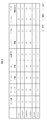
- surface which shows permission, restriction
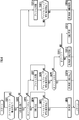
- the flowchart which shows idle stop control.
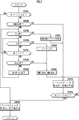
- the flowchart which shows the starting control of the internal combustion engine in EV driving
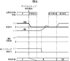
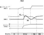
- the time chart which shows starting control of the internal combustion engine by clutch starting.
- (A), (b), and (c) are collinear diagrams which show the change according to the time passage of the starting control of the internal combustion engine by IMA starting.
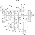
- Explanatory drawing which shows another automatic transmission with which the hybrid vehicle which concerns on embodiment of this invention is provided.
- the hybrid vehicle includes an internal combustion engine ENG composed of an engine, an electric motor MG, a power storage device BATT composed of a secondary battery that exchanges electric power with the electric motor MG, an automatic transmission 1, and an internal combustion engine ENG, an electric motor MG, A power control unit ECU (Electronic Control Unit) for controlling each part of the automatic transmission 1 is provided.
- an internal combustion engine ENG composed of an engine
- an electric motor MG a power storage device BATT composed of a secondary battery that exchanges electric power with the electric motor MG, an automatic transmission 1
- an internal combustion engine ENG an electric motor MG
- a power control unit ECU Electric Control Unit
- the automatic transmission 1 includes an engine output shaft 2 to which driving force (output torque) of the internal combustion engine ENG is transmitted, and an output gear that outputs power to left and right front wheels as drive wheels via a differential gear (not shown).
- An output member 3 and a plurality of gear trains G2 to G5 having different speed ratios are provided.
- the automatic transmission 1 includes a first input shaft 4 that rotatably supports the drive gears G3a and G5a of the odd-numbered gear trains G3 and G5 that establish odd-numbered gear positions in the gear ratio order, and a gear ratio.
- a second input shaft 5 that rotatably supports drive gears G2a and G4a of even-numbered gear trains G2 and G4 that establish even-numbered gear positions in order, and a reverse shaft 6 that rotatably supports reverse gear GR Is provided.
- the first input shaft 4 is disposed on the same axis as the engine output shaft 2, and the second input shaft 5 and the reverse shaft 6 are disposed in parallel with the first input shaft 4.
- the automatic transmission 1 includes an idle drive gear Gia rotatably supported on the first input shaft 4, a first idle driven gear Gib fixed to the idle shaft 7 and meshed with the idle drive gear Gia, There is provided an idle gear train Gi composed of a second idle driven gear Gic fixed to the input shaft 5 and a third idle driven gear Gid fixed to the reverse shaft 6 and meshed with the first idle drive gear Gib.
- the idle shaft 7 is arranged in parallel with the first input shaft 4.
- the automatic transmission 1 includes a first clutch C1 and a second clutch C2 which are hydraulically operated dry friction clutches or wet friction clutches.
- the first clutch C1 is configured to be switchable between a transmission state in which the driving force of the internal combustion engine ENG transmitted to the engine output shaft 2 is transmitted to the first input shaft 4 and an open state in which this transmission is cut off.
- the second clutch C2 is configured to be switchable between a transmission state in which the driving force of the internal combustion engine ENG transmitted to the engine output shaft 2 is transmitted to the second input shaft 5 and an open state in which this transmission is interrupted.
- Both clutches C1 and C2 are preferably operated by an electric actuator so that the state can be quickly switched. Both clutches C1 and C2 may be operated by a hydraulic actuator.
- the automatic transmission 1 is provided with a planetary gear mechanism PG which is a differential rotation mechanism and is positioned coaxially with the engine output shaft 2.
- the planetary gear mechanism PG is configured as a single pinion type that includes a sun gear Sa, a ring gear Ra, and a carrier Ca that pivotally supports and rotates a pinion Pa that meshes with the sun gear Sa and the ring gear Ra.
- Three rotation elements including the sun gear Sa, the carrier Ca, and the ring gear Ra of the planetary gear mechanism PG are separated by a distance corresponding to a gear ratio in a speed diagram (a diagram showing a relative rotation speed of each rotation element as a straight line).
- a speed diagram a diagram showing a relative rotation speed of each rotation element as a straight line.
- the sun gear Sa as the first rotation element is fixed to the first input shaft 4.
- the carrier Ca as the second rotating element is connected to the third speed drive gear G3a of the third speed gear train G3.
- the ring gear Ra which is the third rotating element, is fixed to a stationary part such as a transmission case by a lock mechanism R1 so as to be releasable.
- the lock mechanism R1 is configured by a synchromesh mechanism that can be switched between a fixed state in which the ring gear Ra is fixed to the non-moving portion and an open state in which the ring gear Ra is freely rotatable.
- the lock mechanism R1 is not limited to the synchromesh mechanism, and includes a friction engagement release mechanism such as a sleeve, a wet multi-plate brake, a hub brake, a band brake, a one-way clutch, a two-way clutch, and the like. May be.
- a friction engagement release mechanism such as a sleeve, a wet multi-plate brake, a hub brake, a band brake, a one-way clutch, a two-way clutch, and the like. May be.
- the planetary gear mechanism PG is a double pinion type comprising a sun gear, a ring gear, and a carrier that supports a pair of pinions Pa and Pa ′ that are meshed with each other and one is a sun gear and the other is meshed with the ring gear.
- You may comprise.
- the sun gear (first rotating element) is fixed to the first input shaft 4
- the ring gear (second rotating element) is connected to the third speed drive gear G3a of the third speed gear train G3, and the carrier (third rotation)
- the element) may be configured to be releasably fixed to the non-moving portion by the lock mechanism R1.
- a hollow electric motor MG (motor / generator) is arranged outside the planetary gear mechanism PG in the radial direction.
- the planetary gear mechanism PG is disposed inside the hollow electric motor MG.
- the electric motor MG includes a stator MGa and a rotor MGb.
- the electric motor MG is controlled via the power drive unit PDU based on the instruction signal from the power control device ECU.
- the power control unit ECU generates the power drive unit PDU by driving the electric motor MG while consuming the electric power of the power storage device BATT and suppressing the rotational force of the rotor MGb, and the generated electric power is transmitted via the power drive unit PDU.
- the regeneration state in which the power storage device BATT is charged is appropriately switched.
- the first driven gear Go1 meshing with the second speed drive gear G2a and the third speed drive gear G3a is fixed to the output shaft 3a that supports the output member 3.
- a second driven gear Go2 that meshes with the fourth speed drive gear G4a and the fifth speed drive gear G5a is fixed to the output shaft 3a.
- a parking gear GP is fixed to the output shaft 3a.
- the shaft length of the transmission can be shortened, and the FF (front wheel drive) system can be mounted on a vehicle.
- the first input shaft 4 is composed of a synchromesh mechanism, and the third speed drive gear G3a and the first input shaft 4 are connected to each other.
- the fifth speed drive gear G5a and the first input shaft 4 are connected to each other.
- 1st meshing which is the 1st selection means which can be changed to any state of the neutral state which cuts connection with the 5th speed side connection state, 3rd speed drive gear G3a and 5th speed drive gear G5a, and the 1st input shaft 4
- a mechanism SM1 is provided.
- the second input shaft 5 is configured by a synchromesh mechanism, and is connected to the second speed drive gear G5a and the second input shaft 5 in the second speed connected state in which the second speed drive gear G2a and the second input shaft 5 are connected.
- the second meshing means which is the second selection means that can be switched to any one of the neutral state in which the connection between the second-speed drive gear G2a and the fourth-speed drive gear G5a and the second input shaft 5 is disconnected.
- a mechanism SM2 is provided.
- a reverse driven gear GRa that meshes with the reverse gear GR is fixed to the first input shaft 4.
- the reverse shaft 6 includes a synchromesh mechanism, and a third meshing mechanism SM3 that can be switched between a connected state in which the reverse gear GR and the reverse shaft 6 are connected and a neutral state in which the connection is broken is selectable. Is provided.
- the ring gear Ra of the planetary gear mechanism PG is fixed by the lock mechanism R1, and the first clutch C1 is engaged to establish the transmission state.
- the driving force of the internal combustion engine ENG is input to the sun gear Sa of the planetary gear mechanism PG via the engine output shaft 2, the first clutch C1, and the first input shaft 4, and the internal combustion engine ENG input to the engine output shaft 2 is input.
- the rotational speed is reduced to 1 / (g + 1) and transmitted to the third speed drive gear G3a via the carrier Ca.
- the driving force transmitted to the third-speed drive gear G3a is the gear ratio of the third-speed gear train G3 composed of the third-speed drive gear G3a and the first driven gear Go1 (number of teeth of the third-speed drive gear G3a / first driven gear).
- the number of teeth of Go1) is i, and the gear is shifted to 1 / i (g + 1) and output from the output member 3 via the first driven gear Go1 and the output shaft 3a, and the first gear is established.
- the first gear stage can be established by the planetary gear mechanism PG and the third speed gear train, so that a meshing mechanism dedicated to the first speed stage is not required, and the axial length of the automatic transmission is shortened. be able to.
- the power control device ECU performs a decelerating regenerative operation in which power is generated by applying a brake with the electric motor MG. I do. Further, according to the remaining capacity SOC of the power storage device BATT, the electric motor MG is driven to drive the HEV (Hybrid Electric Vehicle) that assists the driving force of the internal combustion engine ENG, or EV (Electric that runs only with the driving force of the electric motor MG). Vehicle) can run.
- HEV Hybrid Electric Vehicle
- the driving force of the electric motor MG is used by gradually engaging the first clutch C1.
- the internal combustion engine ENG can be started using the kinetic energy of the vehicle.
- the second meshing mechanism SM2 is set to 2
- the second-speed side connected state in which the high-speed driving gear G2a and the second input shaft 5 are connected or the pre-shift state approaching this state is set.
- the second meshing mechanism SM2 is brought into the second speed connected state in which the second speed driving gear G2a and the second input shaft 5 are connected, The clutch C2 is engaged and the transmission state is established.
- the driving force of the internal combustion engine ENG is output from the output member 3 via the second clutch C2, the idle gear train Gi, the second input shaft 5, the second speed gear train G2, and the output shaft 3a.
- the first meshing mechanism SM1 is connected to the third speed side where the third speed drive gear G3a and the first input shaft 4 are connected, or The pre-shift state is approaching this state.
- the upshift or the downshift can be performed simply by setting the first clutch C1 in the transmission state and the second clutch C2 in the disengaged state, and smoothly switching the shift speed without interrupting the driving force. Can do.
- the power control unit ECU performs a decelerating regenerative operation according to the remaining capacity SOC of the power storage device BATT.
- the deceleration regenerative operation in the second speed stage it differs depending on whether the first meshing mechanism SM1 is in the third speed side connected state or in the neutral state.
- the third drive gear G3a rotated by the first driven gear Go1 rotated by the second drive gear G2a is connected to the electric motor MG via the first input shaft 4.
- the rotation of the rotor MGb is suppressed and a brake is applied to generate electricity and perform regeneration.
- the rotation speed of the ring gear Ra is set to “0” by setting the lock mechanism R1 in a fixed state, and the gear rotates with the third speed drive gear G3a meshing with the first driven gear Go1.
- the rotation of the carrier Ca to be performed is generated by the electric motor MG connected to the sun gear Sa, so that the brake is applied and regeneration is performed.
- the first meshing mechanism SM1 When HEV traveling is performed at the second speed, for example, the first meshing mechanism SM1 is set to the third speed side connection state in which the third speed drive gear G3a and the first input shaft 4 are connected, and the lock mechanism R1 is opened.
- the planetary gear mechanism PG can be made in a state in which the rotating elements are not relatively rotatable, and the driving force of the electric motor MG is transmitted to the output member 3 via the third-speed gear train G3.
- the first meshing mechanism SM1 is set to the neutral state, the lock mechanism R1 is set to the fixed state, the rotation speed of the ring gear Ra is set to “0”, and the driving force of the electric motor MG is transmitted to the first driven gear Go1 through the first-speed path. Therefore, HEV traveling at the second gear can be performed.
- the first meshing mechanism SM1 When establishing the third speed stage using the driving force of the internal combustion engine ENG, the first meshing mechanism SM1 is set to the third speed side connected state in which the third speed drive gear G3a and the first input shaft 4 are connected to each other.
- the clutch C1 is engaged to establish a transmission state.
- the driving force of the internal combustion engine ENG is transmitted to the output member 3 via the engine output shaft 2, the first clutch C1, the first input shaft 4, the first meshing mechanism SM1, and the third speed gear train G3.
- the output speed is / i.
- the first meshing mechanism SM1 is in the third speed side connected state in which the third speed drive gear G3a and the first input shaft 4 are connected, so the sun gear Sa of the planetary gear mechanism PG, the carrier Ca, Are the same rotation.
- each rotating element of the planetary gear mechanism PG becomes a state in which relative rotation is impossible, and if the sun gear Sa is braked by the electric motor MG, deceleration regeneration is performed, and if the driving force is transmitted to the sun gear Sa by the electric motor MG, HEV traveling is performed. be able to. Further, EV traveling is also possible in which the first clutch C1 is opened and the vehicle travels only with the driving force of the electric motor MG.
- the power control unit ECU sets the second meshing mechanism SM2 to the second speed drive gear G2a and the second input when a downshift is predicted based on vehicle information such as the vehicle speed and the accelerator pedal opening.
- the second meshing mechanism SM2 is connected to the fourth-speed drive gear G4a and the second input shaft 5. It is set as the 4th speed side connection state to connect, or the pre-shift state which approaches this state.
- the second meshing mechanism SM2 is brought into a fourth speed side connected state in which the fourth speed driving gear G4a and the second input shaft 5 are connected, The clutch C2 is engaged and the transmission state is established.
- the first meshing mechanism SM1 is connected to the third speed drive gear G3a and the first input shaft 4 to the third speed.
- a side connected state or a pre-shift state approaching this state is set.
- the first meshing mechanism SM1 is connected to the fifth speed drive gear G5a and the first input shaft 4 in the fifth speed side connected state, or The pre-shift state is approached to this state.
- it is possible to perform downshift or upshift by simply engaging the first clutch C1 and setting it to the transmission state, and releasing the second clutch C2 so that the shift is smooth without interruption of the driving force. Can be done.
- the first meshing mechanism SM1 When performing deceleration regeneration or HEV traveling during traveling at the fourth speed stage, the first meshing mechanism SM1 is connected to the third speed driving gear G3a and the first input shaft 4 when the power transmission device ECU predicts a downshift. If the brake is applied by the electric motor MG, the decelerating regeneration can be performed, and the HEV running can be performed if the driving force is transmitted.
- the first meshing mechanism SM1 When the power control unit ECU is predicting an upshift, the first meshing mechanism SM1 is brought into a fifth speed connected state in which the fifth speed drive gear G5a and the first input shaft 4 are connected, and if the brake is applied by the motor MG, the speed is reduced. If driving force is transmitted from the regenerative electric motor MG, HEV traveling can be performed.
- the first meshing mechanism SM1 is brought into a fifth speed connected state in which the fifth speed driving gear G5a and the first input shaft 4 are connected.
- HEV traveling can be performed if the driving force is output from the electric motor MG. If the electric motor MG brakes and generates electric power, deceleration regeneration can be performed.
- the internal combustion engine ENG can be started by gradually engaging the first clutch C1 during EV traveling at the fifth speed.
- the power control device ECU sets the second meshing mechanism SM2 to the fourth speed drive gear G4a and the second input shaft 5 when a downshift from the vehicle information to the fourth speed is predicted during traveling at the fifth speed.
- the third meshing mechanism SM3 When the reverse speed is established using the driving force of the internal combustion engine ENG, the third meshing mechanism SM3 is in a connected state in which the reverse gear GR and the reverse shaft 6 are connected, the second clutch C2 is engaged, and the transmission state is set. To do. As a result, the rotational speed of the engine output shaft 2 is shifted to minus rotation (reverse rotation) and output from the output member 3 to establish the reverse gear.
- the first meshing mechanism SM1 When performing deceleration regeneration or HEV traveling in the reverse speed, the first meshing mechanism SM1 is set to the third speed side connected state in which the third speed drive gear G3a and the first input shaft 4 are connected, and the lock mechanism R1 is set to the open state.
- the planetary gear mechanism PG is brought into a state in which the rotating elements are not relatively rotatable. Then, if a forward driving force is generated on the rotating rotor MGb and the brake is applied, deceleration regeneration is performed, and HEV traveling can be performed if the reverse driving force is generated. Further, the reverse gear by EV traveling can be established by setting both the clutches C1 and C2 in the released state, the lock mechanism R1 in the fixed state, and rotating the electric motor MG in reverse.
- the vehicle is provided with a brake mechanism B for braking the running of the vehicle.
- a brake mechanism B for braking the running of the vehicle.
- the brake mechanism B is a disc brake or the like, and is controlled by the power control device ECU.
- the vehicle also includes a gradient sensor 11 that detects the gradient D of the road surface on which the vehicle contacts, a brake pedal sensor 12 that detects whether or not the brake pedal is depressed, a vehicle speed sensor 13 that measures the traveling speed of the vehicle, and an accelerator pedal.
- An accelerator pedal sensor 14 for detecting the opening is provided. The detection signals of these sensors 11 to 14 are input to the power control device ECU.
- the power control device ECU includes a region determination unit 21 that detects the remaining capacity SOC of the battery BATT and determines a region (zone) based on the detected remaining capacity SOC.
- the predetermined value of the remaining capacity SOC of the power storage device BATT that makes it impossible to start the internal combustion engine ENG by driving the electric motor MG with the electric power from the power storage device BATT differs according to the gradient D of the road surface on which the vehicle contacts the ground.
- the area discriminating means 21 performs the area division by adding the gradient D detected by the gradient sensor 11 to the remaining capacity SOC.
- the threshold value of each region is constant up to a predetermined gradient Da where the gradient D is greater than 0 degrees.
- the threshold value is set to increase as the gradient D increases.
- the threshold value of each area may be set in consideration of other factors such as the temperature of the battery BATT.
- the areas are the normal use area and the reference zone A zone, and the remaining capacity SOC is smaller than the A zone, and the discharge is partially restricted. It is divided into a C zone which is a discharge restriction region where the remaining capacity SOC is small and discharge is restricted, and a D zone which is a charge restriction region where the remaining capacity SOC is larger than the A zone and charging is restricted.
- the A zone is further divided into an intermediate region A zone M in which the remaining capacity SOC is optimal, an A zone L in which the remaining capacity SOC is smaller than the A zone M, and an A zone H in which the remaining capacity SOC is larger than the A zone M. .
- the region discriminating means 21 corresponds to the remaining capacity detecting means in the present invention, and the threshold values of the B zone L and the C zone correspond to the remaining capacity threshold values in the present invention.
- the power control device ECU controls the internal combustion engine ENG, the electric motor MG, and the automatic transmission 1 based on the region determined by the region determining means 21. As shown in FIG. 3, the power control device ECU permits, restricts, and prohibits various operations based on the area.
- the idle stop release request is issued when the brake pedal sensor 12 detects that the brake pedal is not depressed, or when the accelerator pedal sensor 14 detects the opening degree of the accelerator pedal exceeding a predetermined value. It is determined that it has occurred.
- the rotation speed of the rotor MGb of the electric motor MG is adjusted so that the rotation speed of the ring gear Ra becomes “0”, and the brake B1 is kept in the reverse rotation preventing state while maintaining the driving force of the electric motor MG as “0”.
- the driving force of the electric motor MG is increased.
- the driving of the internal combustion engine ENG may be stopped and the first clutch C1 may be released at that time.
- the first clutch C1 is once engaged and brought into a transmission state.
- the vehicle is started by EV traveling while continuing to drive the internal combustion engine ENG (STEP 12).
- the brake mechanism B is in the vehicle braking state
- the first clutch C1 is in the transmission state
- the first meshing mechanism SM1 is in the neutral state.
- the vehicle is started by the driving force of the internal combustion engine ENG (STEP 13).
- the vehicle braking state by the brake mechanism B is released, the brake B1 is set in the reverse rotation prevention state, the ring gear Ra of the planetary gear mechanism PG is set in the fixed state, and the first gear is set. After the establishment, the first clutch C1 is gradually engaged to establish a transmission state.
- the idle stop control means 21 performs appropriate idle stop control according to the zone determined by the area determination means 21 based on the remaining capacity SOC of the power storage device BATT, so that the vehicle can be started reliably. It becomes possible.
- the vehicle can be started by the driving force of the internal combustion engine ENG even in the C zone where it is impossible to start the internal combustion engine ENG by the driving force of the electric motor MG by the electric power of the power storage device BATT.
- the internal clutch engine ENG is immediately driven by engaging the first clutch C1 and bringing it into the connected state.
- the vehicle can be driven by force.
- the first clutch C1 is brought into the connected state to immediately start the internal combustion engine ENG. It becomes possible to drive the vehicle by applying a driving force.
- control during EV travel of the hybrid vehicle will be described with reference to FIG.
- the following processing is executed by the power control device ECU corresponding to the control means in the present invention.
- the vehicle determines whether or not the area determined by the area determination means 21 is A zone L or more (STEP 21).
- the vehicle continues to travel with the idle stop, EV travel, and EV start permitted (STEP 22).
- the predetermined threshold value S0 is a vehicle speed at which the internal combustion engine ENG can be started, and is, for example, 10 km / h.
- the second meshing mechanism SM2 is set to the second gear side connected state to the second gear preshift state. Thereafter, the second clutch C2 is gradually engaged. At this time, since the driving force transmitted to the output shaft 3a is reduced due to the friction of the second clutch C2, the driving force Tm of the electric motor MG is increased to compensate for this reduction.
- the ignition plug (not shown) is ignited to start the internal combustion engine ENG.
- the second clutch C2 is engaged to establish a transmission state.
- the driving force Tm of the electric motor MG is decreased in accordance with the increase of the driving force Te of the internal combustion engine ENG, and finally the vehicle is driven only by the driving force Te of the internal combustion engine ENG.
- the internal combustion engine ENG is started by normal IMA start (STEP 30). After that, until the area becomes equal to or higher than the A zone L (STEP 25: YES), the vehicle continues to run with the idle stop, EV running, and EV start prohibited (STEP 24).
- the driving force Tm generated by the electric motor MG is equal to or lower than the driving force T0 that can release the connected state of the first meshing mechanism SM1 (STEP 32), and the driving force Tm generated by the electric motor MG is driven.
- the force T0 is exceeded (STEP 32: NO)
- the driving force Tm generated by the electric motor MG is gradually reduced (STEP 33). Note that when the driving force Tm of the electric motor MG is gradually reduced, the higher the vehicle speed S, the greater the shock. Therefore, it is preferable to decrease the decrease rate of the driving force Tm of the electric motor MG as the vehicle speed S detected by the vehicle speed sensor 13 is faster.
- the third gear connected state of the first meshing mechanism SM1 is first released to a neutral state.
- the vehicle speed S is an extremely low speed less than a predetermined threshold value S0, and the rotational speed of the carrier Ca connected to the output shaft 3a is reduced by the running resistance, but the output shaft 3a
- the rotational speed of the sun gear Sa fixed to the first input shaft 4 that is no longer connected to increases, and the ring gear Ra reverses.
- the vehicle continues to run with the idle stop, EV running, and EV start prohibited (STEP 24) until the area is greater than or equal to the A zone L (STEP 25: YES).
- the driving of the electric motor MG is performed until the connected state of the first meshing mechanism SM1 becomes the releasable driving force T0. After gradually reducing the force Tm, the connection state of the first meshing mechanism SM1 is released, and the first clutch C1 is brought into the connected state, thereby starting the internal combustion engine ENG.
- the internal combustion engine ENG is surely started before the remaining capacity SOC of the power storage device BATT becomes less than a value at which the electric motor MG can be driven by the electric power of the power storage device BATT to start the internal combustion engine ENG. be able to.
- the internal combustion engine ENG is started by putting the first clutch C1 into the connected state, so that the driving force (retraction torque) due to the start of the internal combustion engine ENG is output. It is not transmitted to the member 3. Furthermore, since the electric motor MG can be used only for starting the internal combustion engine ENG, the internal combustion engine ENG can be reliably started.
- the electric power of the power storage device BATT is used.
- the internal combustion engine ENG is started by driving. Therefore, it is possible to prevent the remaining capacity SOC of the power storage device BATT from decreasing by starting the internal combustion engine ENG before the EV travel is continued and the remaining capacity SOC of the power storage device BATT decreases to become the C zone. It becomes.
- the internal combustion engine ENG is started by engaging the first clutch C1 and setting the transmission state.
- the internal combustion engine ENG is determined by engaging the second clutch C2 and setting the transmission state. Can also be started.
- the automatic transmission provided in the hybrid vehicle according to the present invention is not limited to the above-described automatic transmission 1 having the fifth forward speed and the first reverse speed.
- the automatic transmission 1 ⁇ / b> A having a high speed may be used.
- the automatic transmission 1A includes a plurality of gear trains G2 to G7 having different gear ratios, and the first input shaft 4 is rotatably supported by drive gears G3a, G5a, G7a of odd-numbered gear trains G3, G5, G7.
- the second input shaft 5 is rotatably supported by drive gears G2a, G4a, G6a of even-numbered gear trains G2, G4, G6.
- the output shaft 3a includes a first driven gear Go1, which meshes with the second speed drive gear G2a and the third speed drive gear G3a, a second driven gear Go2, which meshes with the sixth speed drive gear G6a and the seventh speed drive gear G7a, and a fourth speed drive gear.
- a third driven gear Go3 that meshes with G4a and the fifth-speed drive gear G5a is fixed.
- first input shaft 4 is connected to the third speed drive gear G3a and the first input shaft 4 in the third speed side connection state, and the seventh speed drive gear G7a and the first input shaft 4 are connected to the seventh speed side connection.
- a first meshing mechanism SM1 which is a first selection means which can be switched to any one of a neutral state in which the connection between the state, the third speed driving gear G3a and the seventh speed driving gear G7a and the first input shaft 4 is disconnected. ing.
- the first input shaft 4 is further connected to the fifth speed drive gear G5a and the first input shaft 4 in the fifth speed side connection state, and the fifth speed drive gear G5a and the first input shaft 4 are disconnected from the neutral state.
- a fourth meshing mechanism SM4 which is a first selection means that can be switched to any state, is provided.
- the second input shaft 5 is connected to the second speed drive gear G2a and the second input shaft 5 in the second speed side connected state, the sixth speed drive gear G6a and the second input shaft 5 are connected to the sixth speed side connected state,
- a second meshing mechanism SM2 is provided as second selection means that can be switched to any one of a neutral state in which the connection between the second speed drive gear G2a and the sixth speed drive gear G6a and the second input shaft 5 is disconnected. .
- the second input shaft 5 is further connected to the fourth speed drive gear G4a and the second input shaft 5 in a fourth speed side connection state, and the fourth speed drive gear G4a and the second input shaft 5 are disconnected from each other in a neutral state.
- a fifth meshing mechanism SM5 is provided as a second selection means that can be switched to any state.
- the hybrid vehicle including the automatic transmission 1A configured as described above can perform ENG traveling, HEV traveling, and EV traveling with IMA start, 7th forward speed and reverse speed established, respectively.
- the device ECU executes idle stop control and control during EV traveling.
Landscapes
- Engineering & Computer Science (AREA)
- Transportation (AREA)
- Mechanical Engineering (AREA)
- Chemical & Material Sciences (AREA)
- Combustion & Propulsion (AREA)
- Automation & Control Theory (AREA)
- Power Engineering (AREA)
- Life Sciences & Earth Sciences (AREA)
- Sustainable Development (AREA)
- Sustainable Energy (AREA)
- Hybrid Electric Vehicles (AREA)
- Electric Propulsion And Braking For Vehicles (AREA)
- Control Of Vehicle Engines Or Engines For Specific Uses (AREA)
Abstract
Description
Claims (8)
- 内燃機関と、
電動機と、
前記電動機と電力を授受する蓄電装置と、
第1断接手段を介して選択的に前記内燃機関の駆動力が伝達され、前記電動機に接続された第1入力軸、第2断接手段を介して選択的に前記内燃機関の駆動力が伝達される第2入力軸、及び前記第1入力軸又は前記第2入力軸を出力軸に選択的に連結させる連結手段を有し、前記内燃機関及び前記電動機から出力される動力を変速して前記出力軸に伝達する自動変速機と、
前記蓄電装置の残容量を検知し、検知した残容量に基づき、基準領域、該基準領域より残容量が少ない放電制限領域、該放電制限領域より残容量が少ない放電禁止領域を判別する領域判別手段と、
アイドルストップ要求が発生したとき、前記領域判別手段が判別した領域が前記放電制限領域又は前記放電禁止領域である場合、前記内燃機関を駆動させたまま、前記第1断接手段を接続状態として、前記第1入力軸を回転させることにより、前記蓄電装置の充電を行うよう制御し、その後、アイドルストップ解除要求が発生したとき、前記領域判別手段が判別した領域が前記基準領域である場合、前記内燃機関を停止状態、前記電動機を駆動状態として、当該車両を発進させ、前記領域判別手段が判別した領域が前記放電制限領域である場合、前記内燃機関の駆動を続行し、前記第1断接手段を遮断状態としたまま、前記電動機を駆動して、当該車両を発進させ、前記領域判別手段が判別した領域が前記放電禁止領域である場合、前記内燃機関の駆動を続行し、前記第1断接手段を接続状態として、当該車両を発進させるよう制御するアイドルストップ制御手段とを備えることを特徴とするハイブリッド車両。 - 前記連結手段は、
前記第1入力軸と出力軸を選択的に連結する第1選択手段と、前記第2入力軸と出力軸を選択的に連結する第2選択手段と、前記第1入力軸に接続された第1回転要素、前記出力軸に連結された第2回転要素、及びロック手段が設けられた第3回転要素を互いに差動回転可能に構成した差動回転機構とを含み、
前記アイドルストップ制御手段は、前記アイドルストップ要求が発生したとき、前記領域判別手段が判別した領域が前記放電制限領域又は前記放電禁止領域である場合、前記内燃機関を駆動させたまま、前記第1断接手段を接続状態とし、前記ロック手段により前記第3回転要素をロック解除状態として、前記第1入力軸を回転させることにより、前記蓄電装置の充電を行うよう制御し、その後、前記アイドルストップ解除要求が発生したとき、前記ロック手段により前記第3回転要素をロック状態としてから、当該車両を発進させるよう制御することを特徴とする請求項1に記載のハイブリッド車両。 - 当該車両が接地する路面の勾配を検知する勾配検知手段を備え、
前記連結手段は、前記第1入力軸と出力軸を選択的に連結する第1選択手段と、前記第2入力軸と出力軸を選択的に連結する第2選択手段と、前記第1入力軸に接続された第1回転要素、前記出力軸に連結された第2回転要素、及びロック手段が設けられた第3回転要素を互いに差動回転可能に構成した差動回転機構とを含み、
前記アイドルストップ制御手段は、前記アイドルストップ要求が発生したとき、勾配検知手段が検知した勾配が閾値を超える場合、前記内燃機関を駆動させたまま、前記第1断接手段を接続状態として、前記第1入力軸を回転させることにより、前記蓄電装置の充電を行うよう制御し、その後、前記アイドルストップ解除要求が発生したとき、前記内燃機関の駆動を続行し、前記第1断接手段を遮断状態としたまま、前記電動機を駆動して、当該車両を発進させるよう制御することを特徴とする請求項1に記載のハイブリッド車両。 - 内燃機関と、
電動機と、
前記電動機と電力を授受する蓄電装置と、
第1断接手段を介して選択的に前記内燃機関の駆動力が伝達され、前記電動機に接続された第1入力軸、第2断接手段を介して選択的に前記内燃機関の駆動力が伝達される第2入力軸、前記第1入力軸又は前記第2入力軸に連結される出力軸、前記第1入力軸と前記出力軸とを複数のギヤ列から選択したギヤ列により連結する第1選択手段、及び、前記第2入力軸と前記出力軸とを複数のギヤ列から選択したギヤ列により連結する第2選択手段を有し、前記内燃機関及び前記電動機から出力される動力を変速して前記出力軸に伝達する自動変速機と、
前記蓄電装置の残容量を検知する残容量検知手段と、
当該車両の走行速度を検知する車速検知手段と、
前記第1選択手段が前記第1入力軸と前記出力軸とを前記選択したギヤ列により連結する連結状態にあり、且つ前記電動機のみの駆動力によって当該車両を走行させているとき、前記車速検知手段が検知する車速が閾値以下となり、且つ前記残容量検知手段が検知した残容量が閾値以下になった場合、前記第1選択手段の連結状態が解除可能となるまで前記電動機の駆動力を徐々に低下させた後、前記第1選択手段の連結状態を解除し、前記第1断接手段を接続状態にして、前記内燃機関を始動させるよう制御する制御手段とを備えることを特徴とするハイブリッド車両。 - 当該車両の走行を制動するブレーキを備え、
前記制御手段は、前記電動機の駆動力を徐々に低下させた際に、当該車両が停止したとき、前記ブレーキにより当該車両を停止させた状態を保ちながら、前記電動機の駆動力が略「0」になったとき、前記第1断接手段を接続状態にして、内燃機関を始動させるよう制御することを特徴とする請求項4に記載のハイブリッド車両。 - 当該車両の走行を制動するブレーキを備え、
前記制御手段は、前記内燃機関を始動させる前に当該車両が停止したとき、前記ブレーキを作動させ、前記電動機の駆動力を「0」とすると共に前記第1断接手段を接続状態にして、前記内燃機関を始動させるよう制御することを特徴とする請求項4に記載のハイブリッド車両。 - 当該車両が接地する路面の勾配を検知する勾配検知手段を備え、
前記残容量の閾値は、前記勾配検知手段が検知した勾配に応じて設定されることを特徴とする請求項4から6の何れか1項に記載のハイブリッド車両。 - 前記制御手段は、前記電動機の駆動力を徐々に低下させる際、前記車速検出手段が検出した車速が早いほど、前記駆動力の低下速度を減少させることを特徴とする請求項4から7の何れか1項に記載のハイブリッド車両。
Priority Applications (6)
| Application Number | Priority Date | Filing Date | Title |
|---|---|---|---|
| US13/577,812 US9221329B2 (en) | 2010-03-31 | 2011-03-04 | Hybrid vehicle |
| BR112012024793A BR112012024793A2 (pt) | 2010-03-31 | 2011-03-04 | veículo híbrido |
| JP2012508170A JP5655061B2 (ja) | 2010-03-31 | 2011-03-04 | ハイブリッド車両 |
| RU2012143975/11A RU2529575C2 (ru) | 2010-03-31 | 2011-03-04 | Гибридное транспортное средство |
| CN201180013912.7A CN102803038B (zh) | 2010-03-31 | 2011-03-04 | 混合动力车辆 |
| DE112011101160T DE112011101160T5 (de) | 2010-03-31 | 2011-03-04 | Hybridfahrzeug |
Applications Claiming Priority (4)
| Application Number | Priority Date | Filing Date | Title |
|---|---|---|---|
| JP2010-081299 | 2010-03-31 | ||
| JP2010081300 | 2010-03-31 | ||
| JP2010081299 | 2010-03-31 | ||
| JP2010-081300 | 2010-03-31 |
Publications (1)
| Publication Number | Publication Date |
|---|---|
| WO2011122243A1 true WO2011122243A1 (ja) | 2011-10-06 |
Family
ID=44711972
Family Applications (1)
| Application Number | Title | Priority Date | Filing Date |
|---|---|---|---|
| PCT/JP2011/055104 Ceased WO2011122243A1 (ja) | 2010-03-31 | 2011-03-04 | ハイブリッド車両 |
Country Status (7)
| Country | Link |
|---|---|
| US (1) | US9221329B2 (ja) |
| JP (2) | JP5655061B2 (ja) |
| CN (1) | CN102803038B (ja) |
| BR (1) | BR112012024793A2 (ja) |
| DE (1) | DE112011101160T5 (ja) |
| RU (1) | RU2529575C2 (ja) |
| WO (1) | WO2011122243A1 (ja) |
Cited By (3)
| Publication number | Priority date | Publication date | Assignee | Title |
|---|---|---|---|---|
| US20140121865A1 (en) * | 2012-10-29 | 2014-05-01 | Deere & Company | Methods and Apparatus to Control Motors |
| CN104653318A (zh) * | 2015-01-09 | 2015-05-27 | 奇瑞汽车股份有限公司 | 一种怠速起停车辆的一键启动方法和装置 |
| CN115214611A (zh) * | 2021-03-30 | 2022-10-21 | 本田技研工业株式会社 | 混合动力车辆的控制装置 |
Families Citing this family (14)
| Publication number | Priority date | Publication date | Assignee | Title |
|---|---|---|---|---|
| JP4926209B2 (ja) * | 2009-06-10 | 2012-05-09 | 本田技研工業株式会社 | ハイブリッド車両用の自動変速機 |
| CN102803038B (zh) * | 2010-03-31 | 2015-05-20 | 本田技研工业株式会社 | 混合动力车辆 |
| US20130103241A1 (en) * | 2010-06-28 | 2013-04-25 | Honda Motor Co., Ltd | Vehicle control unit and control method |
| JP5488529B2 (ja) * | 2011-05-17 | 2014-05-14 | マツダ株式会社 | 車両の電源制御装置 |
| CN104442819B (zh) * | 2013-09-13 | 2017-02-22 | 上海汽车集团股份有限公司 | 一种混合动力汽车山路模式的控制方法 |
| JP6343596B2 (ja) * | 2015-10-06 | 2018-06-13 | 本田技研工業株式会社 | デュアルクラッチ式変速機 |
| JP6379146B2 (ja) * | 2016-09-13 | 2018-08-22 | 本田技研工業株式会社 | ハイブリッド車両の制御装置 |
| KR101916073B1 (ko) * | 2016-10-21 | 2018-11-07 | 현대자동차 주식회사 | 하이브리드 전기자동차의 동력전달장치 |
| JP7073622B2 (ja) * | 2016-12-26 | 2022-05-24 | スズキ株式会社 | ハイブリッド車両 |
| JP7013827B2 (ja) | 2017-12-05 | 2022-02-01 | トヨタ自動車株式会社 | ハイブリッド自動車およびこれに搭載される制御装置 |
| CN111491840A (zh) * | 2017-12-18 | 2020-08-04 | 麦格纳国际公司 | 动力传动系控制单元和控制混合动力车辆的变速器的方法 |
| WO2019159625A1 (ja) * | 2018-02-15 | 2019-08-22 | 日立オートモティブシステムズ株式会社 | 駆動装置、及び車両 |
| CN110254434B (zh) * | 2019-05-30 | 2020-12-22 | 上海汽车集团股份有限公司 | 混合动力车怠速充电防溜坡的控制方法 |
| JP2022035372A (ja) * | 2020-08-20 | 2022-03-04 | トヨタ自動車株式会社 | エンジンの始動装置 |
Citations (8)
| Publication number | Priority date | Publication date | Assignee | Title |
|---|---|---|---|---|
| JPH11148390A (ja) * | 1997-11-18 | 1999-06-02 | Honda Motor Co Ltd | ハイブリッド車両 |
| JP2002089594A (ja) * | 2000-07-18 | 2002-03-27 | Luk Lamellen & Kupplungsbau Beteiligungs Kg | 伝動装置 |
| JP2005002866A (ja) * | 2003-06-11 | 2005-01-06 | Nissan Motor Co Ltd | 車両のアイドルストップ制御装置 |
| JP2007291935A (ja) * | 2006-04-25 | 2007-11-08 | Toyota Motor Corp | 内燃機関装置、それを搭載した車両及び内燃機関装置の制御方法 |
| JP2008296897A (ja) * | 2007-05-02 | 2008-12-11 | Nissan Motor Co Ltd | ハイブリッド車両のモード切り替え制御装置 |
| JP2009107502A (ja) * | 2007-10-31 | 2009-05-21 | Hitachi Ltd | ハイブリッド車両の制御装置 |
| JP2009137531A (ja) * | 2007-12-10 | 2009-06-25 | Toyota Motor Corp | 車両の動力出力装置 |
| JP2009166567A (ja) * | 2008-01-11 | 2009-07-30 | Toyota Motor Corp | ハイブリッド車両 |
Family Cites Families (23)
| Publication number | Priority date | Publication date | Assignee | Title |
|---|---|---|---|---|
| JP3129204B2 (ja) * | 1995-10-18 | 2001-01-29 | トヨタ自動車株式会社 | ハイブリッド駆動装置 |
| JP3300294B2 (ja) * | 1998-12-07 | 2002-07-08 | 本田技研工業株式会社 | ハイブリッド車両の制御装置 |
| JP2001055941A (ja) * | 1999-08-16 | 2001-02-27 | Honda Motor Co Ltd | エンジン自動始動停止制御装置 |
| JP4066589B2 (ja) * | 2000-03-06 | 2008-03-26 | トヨタ自動車株式会社 | 内燃機関のアイドリングストップ制御装置およびこれを備える車両 |
| JP3909641B2 (ja) * | 2000-04-05 | 2007-04-25 | スズキ株式会社 | ハイブリッド車両の制御装置 |
| JP3827980B2 (ja) * | 2001-09-21 | 2006-09-27 | 本田技研工業株式会社 | ハイブリッド車両の制御装置 |
| JP3952005B2 (ja) * | 2003-11-18 | 2007-08-01 | 日産自動車株式会社 | ハイブリッド車両の駆動装置 |
| WO2005084335A2 (en) * | 2004-03-01 | 2005-09-15 | Railpower Technologies Corp. | Cabless hybrid locomotive |
| JP4337636B2 (ja) * | 2004-05-31 | 2009-09-30 | マツダ株式会社 | アイドルストップ付き車両の制御装置 |
| JP4086018B2 (ja) | 2004-07-15 | 2008-05-14 | トヨタ自動車株式会社 | ハイブリッド車およびその制御方法並びに動力出力装置 |
| JP4265568B2 (ja) * | 2005-04-28 | 2009-05-20 | 日産自動車株式会社 | ハイブリッド車両のモード遷移制御装置 |
| CN1986304A (zh) * | 2006-12-08 | 2007-06-27 | 奇瑞汽车有限公司 | 一种混合动力汽车的控制方法 |
| CN1986308B (zh) * | 2006-12-08 | 2010-11-17 | 奇瑞汽车股份有限公司 | 一种弱混合轿车用电机控制系统 |
| US8688299B2 (en) | 2007-05-02 | 2014-04-01 | Nissan Motor Co., Ltd. | Mode change control system for hybrid vehicle |
| JP4697247B2 (ja) * | 2008-03-03 | 2011-06-08 | 日産自動車株式会社 | ハイブリッド車両 |
| JP4981713B2 (ja) * | 2008-03-05 | 2012-07-25 | 三菱重工業株式会社 | 内燃機関の吸気冷却装置およびこれを用いた自動車 |
| CN102265261B (zh) * | 2008-12-22 | 2014-07-02 | 丰田自动车株式会社 | 车辆用电子控制系统、车辆用电子控制单元、车辆用控制同步方法 |
| JP2011225206A (ja) * | 2010-03-31 | 2011-11-10 | Honda Motor Co Ltd | 車両用駆動装置の制御装置 |
| BR112012024810A2 (pt) * | 2010-03-31 | 2016-06-07 | Honda Motor Co Ltd | veículo híbrido |
| CN102803038B (zh) * | 2010-03-31 | 2015-05-20 | 本田技研工业株式会社 | 混合动力车辆 |
| DE112011101521T5 (de) * | 2010-04-30 | 2013-06-20 | Honda Motor Co., Ltd. | Hybridfahrzeug-Antriebssystem |
| US9073546B2 (en) * | 2010-06-15 | 2015-07-07 | Honda Motor Co., Ltd. | Hybrid vehicle driving system |
| US8892287B2 (en) * | 2010-07-12 | 2014-11-18 | Honda Motor Co., Ltd | Hybrid vehicle control unit and control method |
-
2011
- 2011-03-04 CN CN201180013912.7A patent/CN102803038B/zh not_active Expired - Fee Related
- 2011-03-04 US US13/577,812 patent/US9221329B2/en not_active Expired - Fee Related
- 2011-03-04 JP JP2012508170A patent/JP5655061B2/ja not_active Expired - Fee Related
- 2011-03-04 RU RU2012143975/11A patent/RU2529575C2/ru not_active IP Right Cessation
- 2011-03-04 BR BR112012024793A patent/BR112012024793A2/pt not_active IP Right Cessation
- 2011-03-04 DE DE112011101160T patent/DE112011101160T5/de not_active Withdrawn
- 2011-03-04 WO PCT/JP2011/055104 patent/WO2011122243A1/ja not_active Ceased
-
2014
- 2014-10-03 JP JP2014204641A patent/JP6067641B2/ja not_active Expired - Fee Related
Patent Citations (8)
| Publication number | Priority date | Publication date | Assignee | Title |
|---|---|---|---|---|
| JPH11148390A (ja) * | 1997-11-18 | 1999-06-02 | Honda Motor Co Ltd | ハイブリッド車両 |
| JP2002089594A (ja) * | 2000-07-18 | 2002-03-27 | Luk Lamellen & Kupplungsbau Beteiligungs Kg | 伝動装置 |
| JP2005002866A (ja) * | 2003-06-11 | 2005-01-06 | Nissan Motor Co Ltd | 車両のアイドルストップ制御装置 |
| JP2007291935A (ja) * | 2006-04-25 | 2007-11-08 | Toyota Motor Corp | 内燃機関装置、それを搭載した車両及び内燃機関装置の制御方法 |
| JP2008296897A (ja) * | 2007-05-02 | 2008-12-11 | Nissan Motor Co Ltd | ハイブリッド車両のモード切り替え制御装置 |
| JP2009107502A (ja) * | 2007-10-31 | 2009-05-21 | Hitachi Ltd | ハイブリッド車両の制御装置 |
| JP2009137531A (ja) * | 2007-12-10 | 2009-06-25 | Toyota Motor Corp | 車両の動力出力装置 |
| JP2009166567A (ja) * | 2008-01-11 | 2009-07-30 | Toyota Motor Corp | ハイブリッド車両 |
Cited By (4)
| Publication number | Priority date | Publication date | Assignee | Title |
|---|---|---|---|---|
| US20140121865A1 (en) * | 2012-10-29 | 2014-05-01 | Deere & Company | Methods and Apparatus to Control Motors |
| US9102334B2 (en) * | 2012-10-29 | 2015-08-11 | Deere & Company | Methods and apparatus to control motors |
| CN104653318A (zh) * | 2015-01-09 | 2015-05-27 | 奇瑞汽车股份有限公司 | 一种怠速起停车辆的一键启动方法和装置 |
| CN115214611A (zh) * | 2021-03-30 | 2022-10-21 | 本田技研工业株式会社 | 混合动力车辆的控制装置 |
Also Published As
| Publication number | Publication date |
|---|---|
| BR112012024793A2 (pt) | 2016-06-07 |
| JP6067641B2 (ja) | 2017-01-25 |
| JP5655061B2 (ja) | 2015-01-14 |
| RU2529575C2 (ru) | 2014-09-27 |
| US20120310462A1 (en) | 2012-12-06 |
| CN102803038A (zh) | 2012-11-28 |
| JPWO2011122243A1 (ja) | 2013-07-08 |
| US9221329B2 (en) | 2015-12-29 |
| RU2012143975A (ru) | 2014-05-10 |
| CN102803038B (zh) | 2015-05-20 |
| DE112011101160T5 (de) | 2013-01-10 |
| JP2015006887A (ja) | 2015-01-15 |
Similar Documents
| Publication | Publication Date | Title |
|---|---|---|
| JP5655061B2 (ja) | ハイブリッド車両 | |
| JP5655063B2 (ja) | ハイブリッド車両 | |
| JP5474980B2 (ja) | ハイブリッド車両のエンジン始動制御装置 | |
| JP5575522B2 (ja) | ハイブリッド車両の動力制御装置 | |
| JP6145412B2 (ja) | 動力伝達装置 | |
| US8684884B2 (en) | Transmission control device and transmission control method | |
| JP5436330B2 (ja) | ハイブリッド車両 | |
| JP5530829B2 (ja) | ハイブリッド車両 | |
| CA2947240C (en) | Clutch device | |
| JP2013043478A (ja) | ハイブリッド車両 | |
| JP5877730B2 (ja) | 軸受止め構造 | |
| JP5923408B2 (ja) | 車両用変速機 | |
| JP5436329B2 (ja) | ハイブリッド車両 | |
| JP2012111262A (ja) | 車両の駆動力制御装置 | |
| JP5575521B2 (ja) | ハイブリッド車両の動力制御装置 | |
| JP5575520B2 (ja) | ハイブリッド車両の動力制御装置 | |
| JP5869377B2 (ja) | 変速機の潤滑構造 |
Legal Events
| Date | Code | Title | Description |
|---|---|---|---|
| WWE | Wipo information: entry into national phase |
Ref document number: 201180013912.7 Country of ref document: CN |
|
| 121 | Ep: the epo has been informed by wipo that ep was designated in this application |
Ref document number: 11762483 Country of ref document: EP Kind code of ref document: A1 |
|
| WWE | Wipo information: entry into national phase |
Ref document number: 2012508170 Country of ref document: JP |
|
| WWE | Wipo information: entry into national phase |
Ref document number: 13577812 Country of ref document: US |
|
| WWE | Wipo information: entry into national phase |
Ref document number: 7378/CHENP/2012 Country of ref document: IN |
|
| WWE | Wipo information: entry into national phase |
Ref document number: 112011101160 Country of ref document: DE Ref document number: 1120111011601 Country of ref document: DE |
|
| WWE | Wipo information: entry into national phase |
Ref document number: 2012143975 Country of ref document: RU |
|
| 122 | Ep: pct application non-entry in european phase |
Ref document number: 11762483 Country of ref document: EP Kind code of ref document: A1 |
|
| REG | Reference to national code |
Ref country code: BR Ref legal event code: B01A Ref document number: 112012024793 Country of ref document: BR |
|
| ENP | Entry into the national phase |
Ref document number: 112012024793 Country of ref document: BR Kind code of ref document: A2 Effective date: 20120928 |