WO2011121743A1 - Contrôleur de démarrage de moteur pour véhicule hybride - Google Patents
Contrôleur de démarrage de moteur pour véhicule hybride Download PDFInfo
- Publication number
- WO2011121743A1 WO2011121743A1 PCT/JP2010/055757 JP2010055757W WO2011121743A1 WO 2011121743 A1 WO2011121743 A1 WO 2011121743A1 JP 2010055757 W JP2010055757 W JP 2010055757W WO 2011121743 A1 WO2011121743 A1 WO 2011121743A1
- Authority
- WO
- WIPO (PCT)
- Prior art keywords
- rotation
- rotating
- rotating element
- center axis
- control device
- Prior art date
Links
Images


Classifications
-
- B—PERFORMING OPERATIONS; TRANSPORTING
- B60—VEHICLES IN GENERAL
- B60K—ARRANGEMENT OR MOUNTING OF PROPULSION UNITS OR OF TRANSMISSIONS IN VEHICLES; ARRANGEMENT OR MOUNTING OF PLURAL DIVERSE PRIME-MOVERS IN VEHICLES; AUXILIARY DRIVES FOR VEHICLES; INSTRUMENTATION OR DASHBOARDS FOR VEHICLES; ARRANGEMENTS IN CONNECTION WITH COOLING, AIR INTAKE, GAS EXHAUST OR FUEL SUPPLY OF PROPULSION UNITS IN VEHICLES
- B60K6/00—Arrangement or mounting of plural diverse prime-movers for mutual or common propulsion, e.g. hybrid propulsion systems comprising electric motors and internal combustion engines ; Control systems therefor, i.e. systems controlling two or more prime movers, or controlling one of these prime movers and any of the transmission, drive or drive units Informative references: mechanical gearings with secondary electric drive F16H3/72; arrangements for handling mechanical energy structurally associated with the dynamo-electric machine H02K7/00; machines comprising structurally interrelated motor and generator parts H02K51/00; dynamo-electric machines not otherwise provided for in H02K see H02K99/00
- B60K6/20—Arrangement or mounting of plural diverse prime-movers for mutual or common propulsion, e.g. hybrid propulsion systems comprising electric motors and internal combustion engines ; Control systems therefor, i.e. systems controlling two or more prime movers, or controlling one of these prime movers and any of the transmission, drive or drive units Informative references: mechanical gearings with secondary electric drive F16H3/72; arrangements for handling mechanical energy structurally associated with the dynamo-electric machine H02K7/00; machines comprising structurally interrelated motor and generator parts H02K51/00; dynamo-electric machines not otherwise provided for in H02K see H02K99/00 the prime-movers consisting of electric motors and internal combustion engines, e.g. HEVs
- B60K6/42—Arrangement or mounting of plural diverse prime-movers for mutual or common propulsion, e.g. hybrid propulsion systems comprising electric motors and internal combustion engines ; Control systems therefor, i.e. systems controlling two or more prime movers, or controlling one of these prime movers and any of the transmission, drive or drive units Informative references: mechanical gearings with secondary electric drive F16H3/72; arrangements for handling mechanical energy structurally associated with the dynamo-electric machine H02K7/00; machines comprising structurally interrelated motor and generator parts H02K51/00; dynamo-electric machines not otherwise provided for in H02K see H02K99/00 the prime-movers consisting of electric motors and internal combustion engines, e.g. HEVs characterised by the architecture of the hybrid electric vehicle
- B60K6/44—Series-parallel type
- B60K6/445—Differential gearing distribution type
-
- B—PERFORMING OPERATIONS; TRANSPORTING
- B60—VEHICLES IN GENERAL
- B60K—ARRANGEMENT OR MOUNTING OF PROPULSION UNITS OR OF TRANSMISSIONS IN VEHICLES; ARRANGEMENT OR MOUNTING OF PLURAL DIVERSE PRIME-MOVERS IN VEHICLES; AUXILIARY DRIVES FOR VEHICLES; INSTRUMENTATION OR DASHBOARDS FOR VEHICLES; ARRANGEMENTS IN CONNECTION WITH COOLING, AIR INTAKE, GAS EXHAUST OR FUEL SUPPLY OF PROPULSION UNITS IN VEHICLES
- B60K6/00—Arrangement or mounting of plural diverse prime-movers for mutual or common propulsion, e.g. hybrid propulsion systems comprising electric motors and internal combustion engines ; Control systems therefor, i.e. systems controlling two or more prime movers, or controlling one of these prime movers and any of the transmission, drive or drive units Informative references: mechanical gearings with secondary electric drive F16H3/72; arrangements for handling mechanical energy structurally associated with the dynamo-electric machine H02K7/00; machines comprising structurally interrelated motor and generator parts H02K51/00; dynamo-electric machines not otherwise provided for in H02K see H02K99/00
- B60K6/20—Arrangement or mounting of plural diverse prime-movers for mutual or common propulsion, e.g. hybrid propulsion systems comprising electric motors and internal combustion engines ; Control systems therefor, i.e. systems controlling two or more prime movers, or controlling one of these prime movers and any of the transmission, drive or drive units Informative references: mechanical gearings with secondary electric drive F16H3/72; arrangements for handling mechanical energy structurally associated with the dynamo-electric machine H02K7/00; machines comprising structurally interrelated motor and generator parts H02K51/00; dynamo-electric machines not otherwise provided for in H02K see H02K99/00 the prime-movers consisting of electric motors and internal combustion engines, e.g. HEVs
- B60K6/22—Arrangement or mounting of plural diverse prime-movers for mutual or common propulsion, e.g. hybrid propulsion systems comprising electric motors and internal combustion engines ; Control systems therefor, i.e. systems controlling two or more prime movers, or controlling one of these prime movers and any of the transmission, drive or drive units Informative references: mechanical gearings with secondary electric drive F16H3/72; arrangements for handling mechanical energy structurally associated with the dynamo-electric machine H02K7/00; machines comprising structurally interrelated motor and generator parts H02K51/00; dynamo-electric machines not otherwise provided for in H02K see H02K99/00 the prime-movers consisting of electric motors and internal combustion engines, e.g. HEVs characterised by apparatus, components or means specially adapted for HEVs
- B60K6/36—Arrangement or mounting of plural diverse prime-movers for mutual or common propulsion, e.g. hybrid propulsion systems comprising electric motors and internal combustion engines ; Control systems therefor, i.e. systems controlling two or more prime movers, or controlling one of these prime movers and any of the transmission, drive or drive units Informative references: mechanical gearings with secondary electric drive F16H3/72; arrangements for handling mechanical energy structurally associated with the dynamo-electric machine H02K7/00; machines comprising structurally interrelated motor and generator parts H02K51/00; dynamo-electric machines not otherwise provided for in H02K see H02K99/00 the prime-movers consisting of electric motors and internal combustion engines, e.g. HEVs characterised by apparatus, components or means specially adapted for HEVs characterised by the transmission gearings
- B60K6/365—Arrangement or mounting of plural diverse prime-movers for mutual or common propulsion, e.g. hybrid propulsion systems comprising electric motors and internal combustion engines ; Control systems therefor, i.e. systems controlling two or more prime movers, or controlling one of these prime movers and any of the transmission, drive or drive units Informative references: mechanical gearings with secondary electric drive F16H3/72; arrangements for handling mechanical energy structurally associated with the dynamo-electric machine H02K7/00; machines comprising structurally interrelated motor and generator parts H02K51/00; dynamo-electric machines not otherwise provided for in H02K see H02K99/00 the prime-movers consisting of electric motors and internal combustion engines, e.g. HEVs characterised by apparatus, components or means specially adapted for HEVs characterised by the transmission gearings with the gears having orbital motion
-
- B—PERFORMING OPERATIONS; TRANSPORTING
- B60—VEHICLES IN GENERAL
- B60K—ARRANGEMENT OR MOUNTING OF PROPULSION UNITS OR OF TRANSMISSIONS IN VEHICLES; ARRANGEMENT OR MOUNTING OF PLURAL DIVERSE PRIME-MOVERS IN VEHICLES; AUXILIARY DRIVES FOR VEHICLES; INSTRUMENTATION OR DASHBOARDS FOR VEHICLES; ARRANGEMENTS IN CONNECTION WITH COOLING, AIR INTAKE, GAS EXHAUST OR FUEL SUPPLY OF PROPULSION UNITS IN VEHICLES
- B60K6/00—Arrangement or mounting of plural diverse prime-movers for mutual or common propulsion, e.g. hybrid propulsion systems comprising electric motors and internal combustion engines ; Control systems therefor, i.e. systems controlling two or more prime movers, or controlling one of these prime movers and any of the transmission, drive or drive units Informative references: mechanical gearings with secondary electric drive F16H3/72; arrangements for handling mechanical energy structurally associated with the dynamo-electric machine H02K7/00; machines comprising structurally interrelated motor and generator parts H02K51/00; dynamo-electric machines not otherwise provided for in H02K see H02K99/00
- B60K6/20—Arrangement or mounting of plural diverse prime-movers for mutual or common propulsion, e.g. hybrid propulsion systems comprising electric motors and internal combustion engines ; Control systems therefor, i.e. systems controlling two or more prime movers, or controlling one of these prime movers and any of the transmission, drive or drive units Informative references: mechanical gearings with secondary electric drive F16H3/72; arrangements for handling mechanical energy structurally associated with the dynamo-electric machine H02K7/00; machines comprising structurally interrelated motor and generator parts H02K51/00; dynamo-electric machines not otherwise provided for in H02K see H02K99/00 the prime-movers consisting of electric motors and internal combustion engines, e.g. HEVs
- B60K6/50—Architecture of the driveline characterised by arrangement or kind of transmission units
- B60K6/54—Transmission for changing ratio
- B60K6/543—Transmission for changing ratio the transmission being a continuously variable transmission
-
- B—PERFORMING OPERATIONS; TRANSPORTING
- B60—VEHICLES IN GENERAL
- B60W—CONJOINT CONTROL OF VEHICLE SUB-UNITS OF DIFFERENT TYPE OR DIFFERENT FUNCTION; CONTROL SYSTEMS SPECIALLY ADAPTED FOR HYBRID VEHICLES; ROAD VEHICLE DRIVE CONTROL SYSTEMS FOR PURPOSES NOT RELATED TO THE CONTROL OF A PARTICULAR SUB-UNIT
- B60W10/00—Conjoint control of vehicle sub-units of different type or different function
- B60W10/04—Conjoint control of vehicle sub-units of different type or different function including control of propulsion units
- B60W10/06—Conjoint control of vehicle sub-units of different type or different function including control of propulsion units including control of combustion engines
-
- B—PERFORMING OPERATIONS; TRANSPORTING
- B60—VEHICLES IN GENERAL
- B60W—CONJOINT CONTROL OF VEHICLE SUB-UNITS OF DIFFERENT TYPE OR DIFFERENT FUNCTION; CONTROL SYSTEMS SPECIALLY ADAPTED FOR HYBRID VEHICLES; ROAD VEHICLE DRIVE CONTROL SYSTEMS FOR PURPOSES NOT RELATED TO THE CONTROL OF A PARTICULAR SUB-UNIT
- B60W20/00—Control systems specially adapted for hybrid vehicles
- B60W20/40—Controlling the engagement or disengagement of prime movers, e.g. for transition between prime movers
-
- F—MECHANICAL ENGINEERING; LIGHTING; HEATING; WEAPONS; BLASTING
- F16—ENGINEERING ELEMENTS AND UNITS; GENERAL MEASURES FOR PRODUCING AND MAINTAINING EFFECTIVE FUNCTIONING OF MACHINES OR INSTALLATIONS; THERMAL INSULATION IN GENERAL
- F16H—GEARING
- F16H15/00—Gearings for conveying rotary motion with variable gear ratio, or for reversing rotary motion, by friction between rotary members
- F16H15/48—Gearings for conveying rotary motion with variable gear ratio, or for reversing rotary motion, by friction between rotary members with members having orbital motion
- F16H15/50—Gearings providing a continuous range of gear ratios
- F16H15/52—Gearings providing a continuous range of gear ratios in which a member of uniform effective diameter mounted on a shaft may co-operate with different parts of another member
-
- F—MECHANICAL ENGINEERING; LIGHTING; HEATING; WEAPONS; BLASTING
- F16—ENGINEERING ELEMENTS AND UNITS; GENERAL MEASURES FOR PRODUCING AND MAINTAINING EFFECTIVE FUNCTIONING OF MACHINES OR INSTALLATIONS; THERMAL INSULATION IN GENERAL
- F16H—GEARING
- F16H37/00—Combinations of mechanical gearings, not provided for in groups F16H1/00 - F16H35/00
- F16H37/02—Combinations of mechanical gearings, not provided for in groups F16H1/00 - F16H35/00 comprising essentially only toothed or friction gearings
- F16H37/06—Combinations of mechanical gearings, not provided for in groups F16H1/00 - F16H35/00 comprising essentially only toothed or friction gearings with a plurality of driving or driven shafts; with arrangements for dividing torque between two or more intermediate shafts
- F16H37/08—Combinations of mechanical gearings, not provided for in groups F16H1/00 - F16H35/00 comprising essentially only toothed or friction gearings with a plurality of driving or driven shafts; with arrangements for dividing torque between two or more intermediate shafts with differential gearing
- F16H37/0833—Combinations of mechanical gearings, not provided for in groups F16H1/00 - F16H35/00 comprising essentially only toothed or friction gearings with a plurality of driving or driven shafts; with arrangements for dividing torque between two or more intermediate shafts with differential gearing with arrangements for dividing torque between two or more intermediate shafts, i.e. with two or more internal power paths
- F16H37/084—Combinations of mechanical gearings, not provided for in groups F16H1/00 - F16H35/00 comprising essentially only toothed or friction gearings with a plurality of driving or driven shafts; with arrangements for dividing torque between two or more intermediate shafts with differential gearing with arrangements for dividing torque between two or more intermediate shafts, i.e. with two or more internal power paths at least one power path being a continuously variable transmission, i.e. CVT
- F16H2037/0866—Power split variators with distributing differentials, with the output of the CVT connected or connectable to the output shaft
- F16H2037/0873—Power split variators with distributing differentials, with the output of the CVT connected or connectable to the output shaft with switching, e.g. to change ranges
-
- F—MECHANICAL ENGINEERING; LIGHTING; HEATING; WEAPONS; BLASTING
- F16—ENGINEERING ELEMENTS AND UNITS; GENERAL MEASURES FOR PRODUCING AND MAINTAINING EFFECTIVE FUNCTIONING OF MACHINES OR INSTALLATIONS; THERMAL INSULATION IN GENERAL
- F16H—GEARING
- F16H37/00—Combinations of mechanical gearings, not provided for in groups F16H1/00 - F16H35/00
- F16H37/02—Combinations of mechanical gearings, not provided for in groups F16H1/00 - F16H35/00 comprising essentially only toothed or friction gearings
- F16H37/06—Combinations of mechanical gearings, not provided for in groups F16H1/00 - F16H35/00 comprising essentially only toothed or friction gearings with a plurality of driving or driven shafts; with arrangements for dividing torque between two or more intermediate shafts
- F16H37/08—Combinations of mechanical gearings, not provided for in groups F16H1/00 - F16H35/00 comprising essentially only toothed or friction gearings with a plurality of driving or driven shafts; with arrangements for dividing torque between two or more intermediate shafts with differential gearing
- F16H37/0833—Combinations of mechanical gearings, not provided for in groups F16H1/00 - F16H35/00 comprising essentially only toothed or friction gearings with a plurality of driving or driven shafts; with arrangements for dividing torque between two or more intermediate shafts with differential gearing with arrangements for dividing torque between two or more intermediate shafts, i.e. with two or more internal power paths
- F16H37/084—Combinations of mechanical gearings, not provided for in groups F16H1/00 - F16H35/00 comprising essentially only toothed or friction gearings with a plurality of driving or driven shafts; with arrangements for dividing torque between two or more intermediate shafts with differential gearing with arrangements for dividing torque between two or more intermediate shafts, i.e. with two or more internal power paths at least one power path being a continuously variable transmission, i.e. CVT
- F16H37/086—CVT using two coaxial friction members cooperating with at least one intermediate friction member
-
- Y—GENERAL TAGGING OF NEW TECHNOLOGICAL DEVELOPMENTS; GENERAL TAGGING OF CROSS-SECTIONAL TECHNOLOGIES SPANNING OVER SEVERAL SECTIONS OF THE IPC; TECHNICAL SUBJECTS COVERED BY FORMER USPC CROSS-REFERENCE ART COLLECTIONS [XRACs] AND DIGESTS
- Y02—TECHNOLOGIES OR APPLICATIONS FOR MITIGATION OR ADAPTATION AGAINST CLIMATE CHANGE
- Y02T—CLIMATE CHANGE MITIGATION TECHNOLOGIES RELATED TO TRANSPORTATION
- Y02T10/00—Road transport of goods or passengers
- Y02T10/60—Other road transportation technologies with climate change mitigation effect
- Y02T10/62—Hybrid vehicles
-
- Y—GENERAL TAGGING OF NEW TECHNOLOGICAL DEVELOPMENTS; GENERAL TAGGING OF CROSS-SECTIONAL TECHNOLOGIES SPANNING OVER SEVERAL SECTIONS OF THE IPC; TECHNICAL SUBJECTS COVERED BY FORMER USPC CROSS-REFERENCE ART COLLECTIONS [XRACs] AND DIGESTS
- Y10—TECHNICAL SUBJECTS COVERED BY FORMER USPC
- Y10T—TECHNICAL SUBJECTS COVERED BY FORMER US CLASSIFICATION
- Y10T74/00—Machine element or mechanism
- Y10T74/13—Machine starters
- Y10T74/131—Automatic
- Y10T74/137—Reduction gearing
Definitions
- the present invention relates to an engine start control device for a hybrid vehicle including at least an engine and a rotating electric machine as power sources.
- a hybrid vehicle having an engine and a rotating electric machine as a power source is known. Further, in this type of hybrid vehicle, there is also known a power split mechanism capable of distributing and outputting input power at a predetermined distribution ratio.
- Patent Document 1 a carrier to which an output shaft of an internal combustion engine (engine) is connected, a sun gear to which a rotation shaft of a first motor / generator (rotary electric machine) is connected, and a drive wheel side are connected.
- a hybrid vehicle including a differential mechanism (power split mechanism) including a planetary gear mechanism having a ring gear is disclosed.
- the hybrid vehicle of Patent Document 1 is different from a power split mechanism having a pinion gear to which the output shaft of the internal combustion engine is connected and a sun gear to which the rotation shaft of the first motor / generator is connected via a clutch.
- the differential mechanism is also provided, and this differential mechanism is used as a starting differential mechanism of the internal combustion engine.
- the rotational shaft of the first motor / generator and the starting differential mechanism are connected by a clutch to reduce the rotational speed of the rotational shaft and transmit it to the output shaft of the internal combustion engine. And cranking the internal combustion engine.
- Patent Document 2 discloses a carrier to which an output shaft of an engine is connected, a sun gear to which a rotation shaft of a first motor / generator is connected, and a ring gear to which a rotation shaft of a second motor / generator is connected.
- a drive system for a hybrid vehicle is disclosed that includes a distribution mechanism (power split mechanism) that includes a planetary gear mechanism having the second motor / generator and that also connects the rotation shaft of the second motor / generator to the drive wheel side.
- the rotational torque of the first motor / generator is transmitted to the engine via the power split mechanism while the vehicle is stopped by a parking brake or the like, and the engine is Cranking.
- Patent Document 3 discloses a drive system for a hybrid vehicle provided with a power split mechanism that distributes engine power to a first motor / generator and a drive wheel at a predetermined distribution ratio.
- a planetary cone mechanism capable of changing the distribution ratio is adopted as the power split mechanism.
- Patent Document 4 listed below has a continuously variable transmission mechanism having a plurality of balls (rolling members) sandwiched between an input disk and an output disk, and changing the gear ratio by adjusting the tilt angle of the balls.
- a planetary gear mechanism (differential mechanism) in which one of the rotating elements is coupled to the output shaft of the continuously variable transmission mechanism is disclosed.
- a sun gear which is one of rotating elements, is connected to an output shaft thereof, a carrier is connected to a driving wheel side, and a ring gear is connected to an output side of a driving force source via a gear group.
- a connected planetary gear mechanism is described.
- the hybrid vehicle disclosed in Patent Document 1 requires a dedicated starting differential mechanism and a clutch for starting the engine, which may increase the size of the drive system by at least that much.
- the first motor / generator capable of generating a large output torque required for the cranking operation is required for starting the engine. / There is a high possibility that the generator is mounted, which may lead to an increase in the size of the drive device.
- an object of the present invention is to provide an engine start control device for a hybrid vehicle that can improve the disadvantages of the conventional example and can suppress an increase in the size of a drive system for engine start.
- the present invention includes first to third rotating elements to which a rotating shaft of a first rotating electrical machine, an output shaft of an engine, and a rotating shaft of a second rotating electrical machine are respectively connected.
- the rotation speeds of the first to third rotating elements are arranged in the order of the first rotating element, the second rotating element, and the third rotating element, and are arranged between the first to third rotating elements using a collinear diagram that is represented by a straight line.
- the differential mechanism divides the rotation speed of the first rotation element by the rotation speed of the third rotation element. The rotation ratio can be changed.
- the rotation ratio between the element and the third rotation element is the first rotation element It is characterized by controlling so that the rotation speed is increased.
- the differential mechanism has a fourth rotation element having a rotation center axis common to the first to third rotation elements, a rotation center axis different from the rotation center axis, and the first rotation.
- a rolling member capable of transmitting power via a contact portion between each of the elements, the third rotating element, and the fourth rotating element, and held by the second rotating element. It is desirable to change the rotation ratio according to the tilt angle of the member.
- the first to third rotating elements have a common rotation center axis, and a radial outer portion of the first rotating element and a radially inner portion of the third rotating element
- a rolling member having a rotation center axis different from the rotation center axis disposed in contact with each other and held by the second rotation element may be provided.
- the differential mechanism includes a fourth rotating element having a rotation center axis common to the first to third rotating elements and disposed in a state where a radially inner portion is in contact with the rolling member.
- a fourth rotating element having a rotation center axis common to the first to third rotating elements and disposed in a state where a radially inner portion is in contact with the rolling member.
- the first to third rotating elements have a common rotation center axis, and a radial inner portion of the first rotating element and a radially outer portion of the third rotating element
- a rolling member having a rotation center axis different from the rotation center axis disposed in contact with each other and held by the second rotation element may be provided.
- the differential mechanism includes a fourth rotating element having a rotation center axis common to the first to third rotating elements and disposed in a state where a radially inner portion is in contact with the rolling member.
- the first rotating element, the third rotating element, the fourth rotating element, and the rolling member can transmit power via a contact portion, and the tilt angle of the rolling member It is desirable to change the rotation ratio according to the above.
- the present invention includes a first rotating electrical machine, a rotating shaft of an engine, an output shaft of an engine, an output shaft directed toward a drive wheel, and a rotating shaft of a second rotating electrical machine connected to each other.
- a fourth rotation element is provided, and the rotation speeds of the first to fourth rotation elements are arranged in the order of the first rotation element, the second rotation element, the third rotation element, and the fourth rotation element, and are expressed in a straight line.
- the differential mechanism includes the first rotation The rotation ratio obtained by dividing the rotation speed of the element by the rotation speed of the third rotation element and the rotation ratio obtained by dividing the rotation speed of the first rotation element by the rotation speed of the fourth rotation element can be changed.
- the rotation of the first rotating electrical machine is transmitted to the output shaft of the engine and the engine When cranking at the time of starting, the rotation ratio between the first rotation element and the third rotation element and the rotation between the first rotation element and the fourth rotation element on the collinear diagram The ratio is controlled so as to increase the rotational speed of the first rotating element.
- the differential mechanism has a rotation center axis different from a common rotation center axis in the first to fourth rotation elements, and the first rotation element, the third rotation element, and the fourth rotation axis.
- a rolling member capable of transmitting power via a contact portion between each of the elements and held by the second rotating element, and adjusting the rotation ratio according to a tilt angle of the rolling member. It is desirable to change it.
- the first to fourth rotating elements have a common rotation center axis, and a radial outer portion of the first rotating element and a radially inner portion of the third rotating element
- a rolling member having a rotation center axis different from the rotation center axis disposed in contact with each other and held by the second rotation element may be provided.
- the rotation ratio between the first rotation element and the third rotation element is made smaller than a predetermined value on the nomograph, and the first rotation element It is desirable that the rotation ratio between the first rotation element and the fourth rotation element be larger than a predetermined value.
- the differential mechanism is capable of transmitting power via a contact portion between the first rotating element, the third rotating element, the fourth rotating element, and the rolling member, and the fourth rotating element It is desirable that the radially inner portion is disposed in contact with the rolling member and the rotation ratio is changed according to the tilt angle of the rolling member.
- the first to fourth rotating elements have a common rotation center axis, and a radial inner portion of the first rotating element and a radially outer portion of the third rotating element
- a rolling member having a rotation center axis different from the rotation center axis disposed in contact with each other and held by the second rotation element may be provided.
- the rotation ratio between the first rotation element and the third rotation element on the collinear diagram is made larger than a predetermined value and the first rotation element It is desirable that the rotation ratio between the first rotation element and the fourth rotation element be smaller than a predetermined value.
- the differential mechanism is capable of transmitting power via a contact portion between the first rotating element, the third rotating element, the fourth rotating element, and the rolling member, and the fourth rotating element It is desirable that the radially inner portion is disposed in contact with the rolling member and the rotation ratio is changed according to the tilt angle of the rolling member.
- the differential mechanism includes a sun roller as the first rotating element, a carrier as the second rotating element, a first disk as the third rotating element, and a second disk as the fourth rotating element. And a planetary ball as the rolling member.
- the differential mechanism includes a first disk as the first rotating element, a carrier as the second rotating element, a sun roller as the third rotating element, and a second disk as the fourth rotating element. And a planetary ball as the rolling member.
- the rotational speed of the second rotating element is set to at least the cranking-required rotational speed on the collinear chart, and the rotational speed of the third rotating element is reduced to 0 at the maximum. It is desirable.
- the engine start control device for a hybrid vehicle can increase the rotation speed of the first rotating element, the torque required for cranking generated by the first rotating electrical machine can be reduced. For this reason, the first rotating electrical machine can generate torque necessary for cranking even with the small torque, and can increase the engine to the rotational speed necessary for starting. Accordingly, the first rotating electrical machine can be reduced in size by reducing its capacity. Thus, the drive system of the hybrid vehicle can be reduced in size. Furthermore, since no special dedicated parts are required for starting the engine, the drive system can be made smaller.
- FIG. 1 is a diagram illustrating an engine start control device for a hybrid vehicle according to the present invention and a drive system according to a first embodiment.
- FIG. 2 is a collinear diagram of the drive system according to the first embodiment.
- FIG. 3 is a diagram showing the power flow of the drive system in the state shown in FIG.
- FIG. 4 is a collinear diagram of the drive system of the first embodiment and illustrates a state when the cranking control of the first embodiment is executed.
- FIG. 5 is a diagram showing the power flow of the drive system in the state shown in FIG.
- FIG. 6 is a diagram illustrating another configuration of the drive system according to the first embodiment.
- FIG. 7 is a collinear diagram of the drive system of Example 2 and shows a state where the temperature of the secondary battery is normal temperature.
- FIG. 1 is a diagram illustrating an engine start control device for a hybrid vehicle according to the present invention and a drive system according to a first embodiment.
- FIG. 2 is a collinear diagram of the
- FIG. 8 is a collinear diagram of the drive system of Example 2, and shows a state when the temperature of the secondary battery is low or high.
- FIG. 9 is a diagram illustrating an example of a planetary gear ratio map according to the temperature of the secondary battery.
- FIG. 10 is a diagram showing another example of a planetary gear ratio map according to the temperature of the secondary battery.
- FIG. 11 is a diagram illustrating an engine start control device for a hybrid vehicle according to the present invention and a drive system according to a third embodiment.
- FIG. 12 is a collinear diagram of the drive system according to the third embodiment and illustrates a state when the cranking control according to the third embodiment is performed.
- FIG. 13 is a diagram showing a power flow of the drive system in the state shown in FIG.
- FIG. 14 is a diagram showing another form of the drive system.
- FIG. 15 is a diagram showing another form of the drive system.
- Example 1 A first embodiment of an engine start control device for a hybrid vehicle according to the present invention will be described with reference to FIGS.
- the engine start control device of the first embodiment is configured by a control device 1 (electronic control device: ECU) shown in FIG.
- the control device 1 may have a control function only for the engine start control device, or may have other control functions. In the first embodiment, the latter is assumed.
- the drive system shown in FIG. 1 includes a plurality of types of power sources and a power transmission system that transmits the power of the power sources to drive wheels (not shown) as a driving force.
- a power source a mechanical power source that uses mechanical energy converted from heat energy as power and an electric power source that uses mechanical energy converted from electric energy as power are prepared.
- this drive system includes an engine 10 that outputs mechanical power (engine torque) from an output shaft (crankshaft) 11 as a mechanical power source.
- the engine 10 may be an internal combustion engine, an external combustion engine, or the like.
- the engine 10 enables operations such as fuel injection and ignition by the control device 1.
- this drive system is configured as any one of the first and second rotating electrical machines 20 and 30 and is a motor, a generator capable of powering driving, or a motor / generator capable of driving both powering and regeneration.
- a motor / generator will be described as an example. Therefore, in the following, the first and second rotating electrical machines 20 and 30 are referred to as first and second motor / generators 20 and 30 (MG1 and MG2), respectively.
- the first and second motor / generators 20 and 30 are configured as, for example, permanent magnet type AC synchronous motors, and enable operations such as power running by the control device 1 via an inverter (not shown).
- the first and second motors / generators 20 and 30 convert electrical energy supplied from the secondary battery 51 via the inverter to mechanical energy during powering driving, and rotate on a rotating shaft 21 coaxial with a rotor (not shown). , 31 outputs mechanical power (motor torque).
- mechanical energy is converted into electrical energy when mechanical power (motor torque) is input from the rotary shafts 21 and 31.
- the electric energy can be stored in the secondary battery 51 as electric power through an inverter, or can be used as electric power for powering driving of the other motor / generator.
- the power transmission system is provided with a power split mechanism 40 capable of distributing and outputting input power at a predetermined distribution ratio.
- the power split mechanism 40 is configured as a differential mechanism that enables differential rotation between a plurality of rotating elements.
- a so-called traction planetary gear mechanism composed of a plurality of rotating elements will be described as an example.
- the power split mechanism 40 includes a sun roller 41, a plurality of planetary balls 42, a carrier 43, and first and second disks 44 and 45 as rotating elements.
- the sun roller 41, the carrier 43, and the first and second disks 44 and 45 have a common rotation center axis X.
- the planetary ball 42 has a rotation center axis different from the rotation center axis X, and performs rotation (rotation) around the rotation center axis and rotation (revolution) around the rotation center axis X.
- the direction along the rotation center axis X is referred to as an axial direction
- the direction around the rotation center axis X is referred to as a circumferential direction.
- the direction orthogonal to the rotation center axis X is referred to as the radial direction, and among these, the inward side is referred to as the radial inner side, and the outward side is referred to as the radial outer side.
- the sun roller 41 is located at the rotation center of the power split mechanism 40, and is configured as, for example, a cylindrical rotating body having the rotation center axis X as the center axis.
- the outer surface of the sun roller 41 serves as a rolling surface when the planetary ball 42 rotates.
- the sun roller 41 may roll each planetary ball 42 by its own rotation operation, or may rotate along with the rolling operation of each planetary ball 42.
- Each planetary ball 42 corresponds to a ball-type pinion in the traction planetary gear mechanism, and is radially equidistant from the radially outer portion (here, the outer peripheral surface) of the sun roller 41 about the rotation center axis X. Deploy. Further, each planetary ball 42 is brought into contact between the radially outer portion of the sun roller 41 and the radially inner portion (here, the inner peripheral surface) of each of the first and second disks 44 and 45. Arrange in the state. The planetary ball 42 enables power transmission between the sun roller 41, the first disk 44, and the second disk 45 through the contact portion.
- this planetary ball 42 is disposed as a rolling member that rotates between the sun roller 41 and the first and second disks 44, 45, it is preferably a perfect spherical body.
- the cross section like a rugby ball may be elliptical.
- the planetary ball 42 is rotatably supported by a support shaft 42a that passes through the center of the planetary ball 42.
- the planetary ball 42 can be rotated relative to the support shaft 42a (that is, rotated) by a bearing (not shown) disposed between the outer peripheral surface of the support shaft 42a. Therefore, the planetary ball 42 can roll on the outer peripheral surface of the sun roller 41 around the support shaft 42a.
- the support shaft 42a is disposed so that its center axis is on a plane including the rotation center axis X.
- the reference position of the support shaft 42a is a position where the center axis is parallel to the rotation center axis X, for example, as shown in FIG.
- the support shaft 42a can swing (tilt) between the reference position and a position inclined from the reference position.
- the tilting is performed in a plane including the center axis of the support shaft 42a and the rotation center axis X. This tilting operation is performed by a shift mechanism attached to both ends of the support shaft 42a protruding from the outer peripheral curved surface of the planetary ball 42.
- the shift mechanism tilts the planetary ball 42 together with the support shaft 42a by operating the tilting arms 46 attached to both ends of the support shaft 42a.
- the tilting arm 46 is a member for applying a tilting force to the support shaft 42a and the planetary ball 42 and tilting the rotation center axis of the planetary ball 42, that is, the center axis of the support shaft 42a.
- a pair of tilting arms 46 is prepared for one support shaft 42 a and one planetary ball 42.
- the tilting arm 46 is formed and arranged in a shape extending in a direction perpendicular to the rotation center axis X.
- the tilting arm 46 is attached to the end of the support shaft 42a at the radially outer end.
- One of the pair of tilting arms 46 moves radially outward and the other moves radially inward, so that a tilting force acts on the support shaft 42 a and the planetary ball 42.
- the tilting arm 46 is housed and held in an operable state in a groove formed in the disk portion 43 a of the carrier 43.
- the grooves are formed radially about the rotation center axis X in accordance with the number and position of the tilting arms 46. Accordingly, each tilting arm 46, the support shaft 42 a and the planetary ball 42 rotate together with the carrier 43.
- the shift mechanism is further provided with a pushing member that moves the tilting arm 46 radially outward or radially inward, and a drive unit that operates the pushing member.
- the tilting force is generated by moving the pushing member in the axial direction and applying the pushing force of the pushing member to the radially inner portion of the tilting arm 46.
- the distal end portions on the radially inner side of the pair of tilting arms 46 that support the support shaft 42a have wall surfaces that face each other in the axial direction and taper toward the radially inner side.
- the respective wall surfaces at both end portions in the axial direction serve as contact surfaces with the tapered surfaces of the respective tilting arms 46, and the contact surfaces are tapered toward the radially outer side.
- the drive unit is, for example, an electric actuator such as an electric motor, a hydraulic actuator, or the like, and its operation is controlled by the control device 1.
- the carrier 43 is a rotating member that can rotate relative to the sun roller 41 and the first and second disks 44 and 45.
- the carrier 43 has a pair of disk parts 43a having the rotation center axis X as a center axis.
- Each of the disk portions 43a is disposed at a position sandwiching the planetary ball 42, the support shaft 42a, the tilting arm 46, and the like in the axial direction.
- each disk part 43a is integrated by the several rod-shaped support part which is not shown in figure.
- the carrier 43 holds the planetary ball 42, the support shaft 42 a and the tilting arm 46 so as not to move relative to the sun roller 41 in the axial direction.
- the carrier 43 rotates the planetary ball 42, the support shaft 42a, and the tilting arm 46 around the rotation center axis X along with the rotation of the carrier 43 by the grooves of the respective disk portions 43a.
- the first and second disks 44 and 45 are rotating members formed in an annular shape or a disk shape having the rotation center axis X as a center axis, and are arranged so as to sandwich the planetary balls 42 facing each other in the axial direction. To do. Specifically, the first and second disks 44 and 45 have contact surfaces that come into contact with the outer peripheral curved surface of each planetary ball 42 in the radial direction. Each of the contact surfaces forms a concave arc surface having a curvature equivalent to the curvature of the outer peripheral curved surface of the planetary ball 42.
- each contact surface is formed so that the distance from the rotation center axis X to the contact portion with each planetary ball 42 is the same length, and each planetary ball of the first and second disks 44 and 45 is formed.
- Each contact angle with respect to 42 is set to the same angle.
- the contact angle is an angle from the reference to the contact portion with each planetary ball 42.
- the radial direction is used as a reference.
- Each contact surface is in point contact or line contact with the outer peripheral curved surface of the planetary ball 42.
- the direction of the contact line in the line contact is a direction orthogonal to the plane when the planetary ball 42 is tilted.
- Each contact surface is radially inward and oblique to the planetary ball 42 when an axial force directed to the planetary ball 42 is applied to the first and second disks 44 and 45. It is formed so that a directional force is applied.
- one of the first disk 44 and the second disk 45 rotates at a higher speed than when it is at the reference position, and the other rotates at a lower speed.
- the second disk 45 rotates at a lower speed (acceleration)
- the planetary ball 42 is counterclockwise in FIG.
- the rotation is higher than that of the first disk 44 (deceleration). Therefore, in the power split mechanism 40, the rotation ratio between the first disk 44 and the second disk 45 can be changed steplessly by changing the tilt angle.
- the pressing portion may be a drive source such as an electric actuator or a hydraulic actuator, and may be a mechanism such as a torque cam that generates a pressing force with the rotation of the first or second disk 44 or 45 to be disposed. There may be.
- the pressing portion is operated to generate a pressing force, whereby a pressing force is generated between the first and second disks 44 and 45 and each planetary ball 42, and a friction is generated between them. Force is generated.
- each planetary ball 42 rolls with the rotation of the sun roller 41 by the frictional force, and the rotational torque due to the rotation of each planetary ball 42 is the first and second disks 44, 45. Rotate these by telling them.
- the carrier 43 rotates around the rotation center axis X together with the planetary ball 42, the support shaft 42 a and the tilting arm 46.
- the rotational torque due to the rotation of each planetary ball 42 accompanying the rotation of the first disk 44 is transmitted to the sun roller 41 and the second disk 45 to rotate them.
- each planetary ball 42 rotates while revolving in conjunction with the rotation of the carrier 43, and the rotational torque due to the rotation is applied to the sun roller 41 and the first and second disks 44, 45. Communicate and rotate them.
- the power split mechanism 40 and the power source (the engine 10 and the first and second motor / generators 20 and 30) are connected as follows.
- the engine 10 connects the output shaft 11 to the carrier 43 (second rotating element).
- the output shaft 11 and the carrier 43 rotate together.
- the first motor / generator 20 connects the rotation shaft 21 to the sun roller 41 (first rotation element).
- the rotating shaft 21 and the sun roller 41 rotate together.
- the second motor / generator 30 connects the rotation shaft 31 to the first disk 44 (third rotation element).
- the rotating shaft 31 and the first disk 44 rotate together.
- the rotation shaft 31 of the second motor / generator 30 also serves as an output shaft on the system directed toward the drive wheel.
- the drive system configured as described above uses a collinear chart that represents the rotation speed (number of rotations) of the first to third rotation elements (the first roller 44 corresponding to the sun roller 41, the carrier 43, and the ring gear) in a straight line.
- Control device 1 controls.
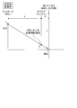
- the collinear chart shown in FIG. 2 is obtained by arranging the coordinate axes in the order of the sun roller 41, the carrier 43, and the first disk 44, and expressing their rotational speeds as straight lines.
- the vertical axis indicates the rotational speed of each rotary element, and in order from the left is the sun roller shaft, the carrier shaft, and the first disk shaft.
- the upper side is positive rotation and the lower side is negative rotation.
- the horizontal axis indicates the relationship of the rotational speed ratio (rotational ratio) of the sun roller 41, the carrier 43, and the first disk 44.
- the carrier axis is determined at a position that internally divides the sun roller axis and the first disk axis in a 1: ⁇ relationship.
- the control device 1 performs start control of the engine 10 using the alignment chart.
- the rotation of the first motor / generator 20 (MG1) is transmitted to the output shaft 11 to crank the engine 10.
- the rotation speed (rotation speed) of the carrier 43 is set to be higher than at least the cranking rotation speed (cranking rotation speed), and the rotation speed of the first disk 44 is reduced.
- the rotational speed of the sun roller 41 increases on the nomograph, so that the cranking required torque of the first motor / generator 20 can be reduced. For example, taking FIG.
- the cranking-required rotational speed refers to a rotational speed necessary for starting that enables fuel injection or the like.
- the cranking in a state where the planetary gear ratio ⁇ is fixed is the same as the cranking operation mode by the power split mechanism composed of the conventional planetary gear mechanism in which the planetary gear ratio ⁇ cannot be changed.
- the upper limit of the rotational speed of the sun roller 41 is restricted by the required cranking rotational speed of the carrier 43 and the rotational speed of the first disk 44 (at least 0). Since the upper limit of the rotational speed of the sun roller 41 is low, the first motor / generator 20 must still generate a large required cranking torque in order to raise the carrier 43 to the required cranking rotational speed.
- the power flow in the drive system at this time is shown in FIG. 3. In order to increase the motor torque (motor power running torque) of the first motor / generator 20 to the cranking required torque, the secondary motor 51 to the first motor / generator A large amount of power must be supplied to 20.
- stationary control is performed in which power is supplied from the secondary battery 51 to stop the rotation of the rotating shaft 31 of the second motor / generator 30.
- the motor torque (the first disk is accompanied with the rotation of the sun roller 41) by supplying the second motor / generator 30 with electric power having a magnitude corresponding to the rotational speed of the sun roller 41 and stopping the rotating shaft 31. 44) is generated.
- the rotational speed of the sun roller 41 is higher, a larger resistance torque is required. Therefore, the supplied power increases as the rotational speed of the sun roller 41 increases. In other words, the resistance torque receives a reaction force from the vehicle (drive wheel) side.
- the fact that the torque required for cranking is large requires a capacity corresponding to that, and the first motor / generator 20 is increased in size by that amount, and the weight is increased. Also, the cost of the motor / generator generally increases as its capacity increases. Further, in order to supply a large amount of electric power, an electric circuit having a capacity capable of withstanding the electric power is required, which leads to an increase in cost.
- the planetary gear ratio ⁇ is set so that the rotational speed of the sun roller 41 connected to the first motor / generator 20 is increased on the alignment chart. Control.
- the planetary gear ratio ⁇ is made smaller than a predetermined value on the alignment chart shown in FIG. 4 to increase the rotational speed of the sun roller 41.
- the rotation speed of the carrier 43 is kept at least the rotation speed necessary for cranking, and the rotation speed of the first disk 44 is made lower than the rotation speed of the carrier 43.
- the rotational speed of the sun roller 41 is higher than that when the planetary gear ratio ⁇ is fixed (broken line) with the control of the planetary gear ratio ⁇ .
- the control device 1 controls the tilt angle of the planetary ball 42 so as to be the required value.
- the rotational speed of the first disk 44 is decelerated to 0 (that is, stationary), which is the maximum.
- the required cranking torque that must be generated by the first motor / generator 20 can be reduced, so that the engine 10 can output the output shaft 11 with the small motor torque of the first motor / generator 20.
- the rotation speed can be increased to the cranking required rotation speed. Therefore, the first motor / generator 20 can be reduced in size and weight by reducing its capacity, and cost can be further reduced.
- the downsizing of the first motor / generator 20 also leads to downsizing of the drive system. Further, since the amount of power supplied to the first motor / generator 20 can be kept low, the cost of the electric circuit can be reduced and the power consumption of the secondary battery 51 can be reduced.
- the first embodiment it is possible to avoid the capacity shortage and the power supply amount shortage of the first motor / generator 20, and the engine 10 can be reliably cranked, so that the startability is improved. Further, in the first embodiment, since no special dedicated parts for starting the engine are required, the engine can be started at a low cost, and the drive system can be further downsized. Furthermore, in the first embodiment, the traction planetary gear mechanism as described above is used for the power split mechanism 40 capable of changing the planetary gear ratio ⁇ , which contributes to miniaturization and cost reduction.
- the predetermined value described above may be determined based on the physique (capacity) of the first motor / generator 20 to be mounted, the required cost value, and the required cost value of the electric circuit. For example, if it is desired to reduce the capacity of the first motor / generator 20, the rotational speed at which the cranking required torque can be generated on the nomograph so as to have an upper limit or a margin to meet the required capacity. Then, the rotational speed of the sun roller 41 is determined, and the planetary gear ratio indicated by a straight line connecting this rotational speed and the cranking required rotational speed of the carrier 43 is set to a predetermined value.
- the first embodiment can be applied not only to the drive system having the above-described configuration but also to the embodiment shown in FIG.
- the drive system shown in FIG. 6 is obtained by arranging the second motor / generator 30 so as to cover the outer peripheral side of the power split mechanism 40 having a substantially cylindrical shape with respect to the drive system of FIG.
- the power split mechanism 40 is disposed in the rotor of the second motor / generator 30 with the rotation center axis X in common.
- the rotating shaft 31 of the second motor / generator 30 is connected to the first disk 44 so as to rotate integrally.
- the rotary shaft 31 is used as the output shaft of the drive system facing the drive wheel.
- the output shaft 60 is arranged separately from the rotary shaft 31. And is connected so as to rotate integrally with the first disk 44.
- This drive system can provide the same operations and effects as the drive system of FIG. Further, in this drive system, the second motor / generator 30 is disposed so as to cover the outer peripheral side of the power split mechanism 40, so that the second motor having a lower rotation and higher torque specification than the first motor / generator 20 is provided.
- the generator 30 can be gathered in a compact manner, and can be reduced in size, weight, and cost as compared with the drive system of FIG.
- the reaction force from the vehicle (drive wheel) side due to the engine torque or the like is received by the stationary control of the second motor / generator 30.
- the stationary control since the stationary control requires the electric power of the secondary battery 51, it may be configured so that the execution of the stationary control becomes unnecessary by receiving the reaction force with the following vehicle stationary device.
- the vehicle stationary device may be a wheel braking device that can adjust the braking force under the control of the control device 1.
- the control device 1 controls the actuator of the braking device to generate a braking force on the wheel that can receive the reaction force.
- a so-called parking device that prevents the vehicle from moving forward and backward during parking can be used as the vehicle stationary device.
- the stationary control of the second motor / generator 30 is not necessary.
- the control device 1 operates the parking device, so that the stationary control of the second motor / generator 30 becomes unnecessary.
- the stationary control of the second motor / generator 30 unnecessary, the power consumption of the secondary battery 51 required for the stationary control can be suppressed, and the fuel consumption can be improved.
- the sun roller 41 is applied as the first rotating element to which the first motor / generator 20 is coupled, and the rotating shaft 31 of the second motor / generator 30 is applied.
- the first disk 44 was applied as a third rotating element to which the output shaft on the system facing the drive wheel is also connected. For this reason, in this example, in order to increase the rotational speed of the sun roller 41 (that is, the first motor / generator 20) during the start control of the engine 10, the planetary gear ratio ⁇ is smaller than a predetermined value on the alignment chart shown in FIG. is doing.
- the power split mechanism may use the first disk 44 as such a first rotating element and also use the sun roller 41 as such a third rotating element.
- the planetary gear ratio ⁇ is made larger than a predetermined value on the alignment chart.
- the alignment chart in this case is obtained by, for example, replacing “MG1” and “MG2, output shaft” in the alignment chart shown in FIG.
- the rotation speed of the carrier 43 is kept at least the cranking-required rotation speed, and the rotation speed of the sun roller 41 is decelerated from the rotation speed of the carrier 43. Therefore, the rotational speed of the first disk 44 increases with the control of the planetary gear ratio ⁇ .
- the rotational speed of the sun roller 41 is decelerated until it reaches a maximum.
- Example 2 Second Embodiment An engine start control device for a hybrid vehicle according to a second embodiment of the present invention will be described with reference to FIGS.
- the engine start control device has the following cranking operation control function together with the cranking operation control function similar to the engine start control device according to the first embodiment described above or separately from the cranking operation control function. Is provided.
- the control target of the engine start control device according to the second embodiment is the drive system illustrated in FIG. 1 or 6 illustrated in the first embodiment.
- the cranking operation control function in the second embodiment will be described in detail below.
- the secondary battery 51 may be able to exhibit its performance without regret, or may cause a decrease in performance. That is, there is no problem if the secondary battery 51 is in the normal temperature range, but if the secondary battery 51 is used in a low temperature range or a high temperature range, the performance may be degraded.
- the temperature range differs for each secondary battery 51 and is determined as a design specification. Then, the reduction in performance of the secondary battery 51 leads to a reduction in its output, leading to a shortage of the amount of power supplied to the first motor / generator 20, so that the rotational speed of the carrier 43 (the output shaft 11 of the engine 10) is cranked.
- the planetary gear ratio ⁇ when the temperature of the secondary battery 51 is normal temperature, the planetary gear ratio ⁇ is made larger than when the temperature is low or high (FIG. 7).
- the control device 1 is configured to make the planetary gear ratio ⁇ smaller (FIG. 8).
- the planetary gear ratio ⁇ may be set using the following map.
- the planetary gear ratio ⁇ has a predetermined value ⁇ a when the temperature t of the secondary battery 51 is in a normal temperature range, a predetermined value ⁇ b in a low temperature range, and a high temperature range as shown in the map of FIG.
- the predetermined value ⁇ c is set ( ⁇ max ⁇ ⁇ a> ⁇ c> ⁇ b ⁇ ⁇ min). “ ⁇ max” is the maximum value of the changeable planetary gear ratio, and “ ⁇ min” is the minimum value of the changeable planetary gear ratio.
- the values of the predetermined values ⁇ a, ⁇ b, and ⁇ c may be determined through experiments and simulations.
- the predetermined value ⁇ a is any value in the planetary gear ratio ⁇ that can maintain the quietness at the start of the engine 10 within the required value in a normal temperature range where the performance of the secondary battery 51 can be fully exhibited.
- the rotational speed of the sun roller 41 can be lowered in the normal temperature range, so that the engine speed can be gradually increased during cranking, and the quietness at the time of engine start is improved.
- the predetermined value ⁇ a may be a minimum or close to the planetary gear ratio ⁇ that can maintain the quietness at the start of the engine 10 within a required value in the normal temperature range.
- the first motor / generator 20 can be reduced in size, weight, and cost as much as possible. Can be reduced in size and the cost of electric circuits can be reduced.
- the predetermined value ⁇ b or the predetermined value ⁇ c is insufficient in the motor torque (motor power running torque) of the first motor / generator 20 due to a decrease in the output of the secondary battery 51 in a low temperature range or a high temperature range where the performance of the secondary battery 51 is observed to decrease.
- the rotational speed of the carrier 43 (the output shaft 11 of the engine 10) can be increased to the cranking required rotational speed even with a small motor torque of the first motor / generator 20.
- the predetermined value ⁇ b is smaller than the predetermined value ⁇ c. This is because the performance of the secondary battery 51 is more likely to deteriorate in the low temperature region than in the high temperature region.
- the quietness at the time of starting the engine in the normal temperature range is improved, and the startability of the engine 10 in the low temperature range and the high temperature range is improved.
- the performance of the secondary battery 51 decreases as the temperature approaches the low temperature range or the high temperature range even in the normal temperature range.
- the planetary gear ratio ⁇ may be set using a map as shown in FIG.
- the temperature at which the best performance is obtained is referred to as normal temperature.
- the predetermined values ⁇ a, ⁇ b, ⁇ c ( ⁇ max ⁇ ⁇ a> ⁇ c> ⁇ b ⁇ ⁇ min) in FIG. 9 are used.
- the map of FIG. 10 is for setting the planetary gear ratio ⁇ to a predetermined value ⁇ a at room temperature. Further, in this map, the planetary gear ratio ⁇ is gradually increased from the predetermined value ⁇ a to the predetermined value ⁇ b as the temperature t decreases from the normal temperature until the temperature t of the secondary battery 51 reaches a certain temperature in the low temperature range. Make it smaller.
- the certain temperature is, for example, a temperature at which the startability of the engine 10 can be secured without reducing the planetary gear ratio ⁇ to the predetermined value ⁇ b even in a low temperature range. If there is no temperature at which such startability can be ensured in the low temperature range, for example, a boundary temperature between the low temperature range and the normal temperature range may be set as the certain temperature.
- the planetary gear ratio ⁇ is gradually increased from the predetermined value ⁇ a to the predetermined value ⁇ c as the temperature t increases from the normal temperature until the temperature t of the secondary battery 51 reaches a certain temperature in the high temperature range. Make it smaller.
- the certain temperature at this time is, for example, a temperature at which startability of the engine 10 can be ensured without reducing the planetary gear ratio ⁇ to the predetermined value ⁇ b even in a high temperature range. If there is no temperature at which such startability can be ensured in the high temperature region, for example, a boundary temperature between the high temperature region and the normal temperature region may be set as the certain temperature.
- the 10 can be used to improve the quietness when starting the engine on the normal temperature side, and to improve the startability of the engine 10 on the low temperature side or the high temperature side.
- Example 3 Third Embodiment An engine start control device for a hybrid vehicle according to a third embodiment of the present invention will be described with reference to FIGS.
- the engine start control device targets the drive system shown in FIG.
- the drive system is obtained by connecting the rotating shaft 31 of the second motor / generator 30 to the second disk 45 instead of the first disk 44 in the drive system shown in FIG.
- the rotating shaft 31 rotates integrally with the second disk 45. Therefore, the drive system of the third embodiment can achieve the same effects as downsizing as the drive system shown in FIG.
- this drive system is controlled by the control device 1 using the alignment chart of FIG.
- coordinate axes are arranged in the order of the sun roller 41 (first rotating element), the carrier 43 (second rotating element), the first disk 44 (third rotating element), and the second disk 45 (fourth rotating element).
- these rotational speeds are represented by straight lines.
- the vertical axis indicates the rotational speed of each rotary element, and in order from the left, is the sun roller axis, the carrier axis, the first disk axis, and the second disk axis.
- the horizontal axis indicates the relationship of the rotation speed ratio (rotation ratio) of the sun roller 41, the carrier 43, the first disk 44, and the second disk 45.
- the carrier axis internally divides the sun roller axis and the first disk axis in a 1: ⁇ 1 relationship, and the carrier axis divides the sun roller axis and the second disk axis in a 1: ⁇ 2 relationship.
- the position is determined.
- the relationship between the first planetary gear ratio ⁇ 1 and the second planetary gear ratio ⁇ 2 is determined by the tilt angle of the planetary ball 42.
- the first speed is set so that the rotational speed of the sun roller 41 connected to the first motor / generator 20 is increased on the alignment chart.
- the second planetary gear ratios ⁇ 1 and ⁇ 2 are controlled. For example, during the starting control of the engine 10, on the collinear chart shown in FIG. 12, the first planetary gear ratio ⁇ 1 is made smaller than the first predetermined value and the second planetary gear ratio ⁇ 2 is made larger than the second predetermined value. Thus, the rotational speed of the sun roller 41 is increased.
- the rotation speed of the carrier 43 is kept at least the cranking-required rotation speed, and the rotation speed of the first disk 44 is decelerated from the rotation speed of the carrier 43. Accordingly, the rotational speed of the sun roller 41 increases with the control of the first and second planetary gear ratios ⁇ 1 and ⁇ 2.
- the control device 1 controls the tilt angle of the planetary ball 42 so as to be the required values.
- the rotational speed of the first disk 44 is decelerated to 0 (that is, stationary), which is the maximum.
- the first planetary gear ratio ⁇ 1 and the second planetary gear ratio ⁇ 2 are within the rotation ratio range (that is, the speed change range) between the first disk 44 (D1) and the second disk 45 (D2) on the collinear chart. Decide to fit within the width.
- the range of the rotation ratio depends on the specifications of the power split mechanism 40.
- one of the first planetary gear ratio ⁇ 1 and the second planetary gear ratio ⁇ 2 is determined, the other is inevitably determined. Therefore, for example, if the main purpose is to reduce the capacity of the first motor / generator 20, the first planetary gear ratio ⁇ 1 may be determined, and the output amount of the motor torque of the second motor / generator 30 is mainly used.
- the second planetary gear ratio ⁇ 2 may be determined.
- the first predetermined value for determining the first planetary gear ratio ⁇ 1 may be determined in the same manner as the predetermined value shown in the first embodiment. For example, on the nomograph, an amount of torque required for cranking that has an upper limit or a margin corresponding to the capacity of the first motor / generator 20 to be calculated (strictly, cranking of the second motor / generator 30 is required).
- the rotational speed of the sun roller 41 is determined at a rotational speed at which it is possible to generate a torque share), and the planetary gear ratio indicated by a straight line connecting this rotational speed and the cranking required rotational speed of the carrier 43 is the first. What is necessary is just to set to a predetermined value.
- the second predetermined value for determining the second planetary gear ratio ⁇ 2 can generate a required cranking torque share that can be output below the horizontal axis or desired to be output on the alignment chart.
- the rotational speed of the second disk 45 may be determined as the rotational speed, and the planetary gear ratio indicated by a straight line connecting this rotational speed and the cranking required rotational speed of the carrier 43 may be set to a second predetermined value.
- the first motor / generator 20 and the second motor / generator 30 share the cranking required torque. That is, in the second embodiment, during engine start control, the engine 10 is cranked using the motor torque of the second motor / generator 30 (the amount of torque required for cranking of the second motor / generator 30). be able to. Further, the cranking required torque share that must be generated by the first motor / generator 20 can be reduced not only for the same reason as in the first embodiment, but also because the motor torque of the second motor / generator 30 can be used. can do.
- the first motor / generator 20 can be reduced in size, weight, and cost as compared to the first embodiment, and the drive system can be further reduced in size and weight, and the electric circuit can be further reduced in cost. Can also be connected. Therefore, in the second embodiment, the startability of the engine 10 can be further improved.
- control device 1 it is desirable for the control device 1 to control the drive system so that the relationship between the first and second motor / generators 20 and 30 satisfies the relationship of the following expression 1 during the cranking control.
- Tmg1 represents the motor torque of the first motor / generator 20
- Tmg2 represents the motor torque of the second motor / generator 30
- Tes indicates the magnitude of the engine torque necessary for starting the engine 10.
- Tmg1 * (1 + ⁇ 1) + Tmg2 * ( ⁇ 2 ⁇ 1) Tes * ⁇ 1 (1)
- Reaction force from the wheel side does not work. That is, in the second embodiment, torque is not transmitted toward the drive wheels when the engine is started, so that generation of drive force in the drive wheels can be suppressed. For this reason, in this case, the occurrence of shock due to the torque transmission can be suppressed, and the stationary operation of the vehicle by the above-described vehicle stationary device or the like is not required during engine start control.
- the sun roller 41 is applied as the first rotating element to which the first motor / generator 20 is connected, and the output on the system toward the drive wheel side is applied.
- the first disk 44 is applied as a third rotating element to which the shaft 60 is connected. Therefore, in this example, in order to increase the rotational speed of the sun roller 41 (that is, the first motor / generator 20) during the start control of the engine 10, the first planetary gear ratio ⁇ 1 is set to the first on the alignment chart shown in FIG. While being smaller than the predetermined value, the second planetary gear ratio ⁇ 2 is larger than the second predetermined value.
- the power split mechanism may use the first disk 44 as such a first rotating element and also use the sun roller 41 as such a third rotating element.
- the first planetary gear ratio ⁇ 1 is made larger than the first predetermined value and the second planetary gear ratio on the alignment chart.
- ⁇ 2 is made smaller than the second predetermined value.
- the alignment chart in this case is obtained by, for example, replacing “MG1” and “output shaft” in the alignment chart shown in FIG.
- the rotation speed of the carrier 43 is kept at least the cranking-required rotation speed, and the rotation speed of the sun roller 41 is decelerated from the rotation speed of the carrier 43. Therefore, the rotational speed of the first disk 44 increases with the control of the first and second planetary gear ratios ⁇ 1 and ⁇ 2.
- the rotational speed of the sun roller 41 is decelerated until it reaches a maximum.
- the output shaft 11 of the engine 10 in each of the first and second embodiments described above is illustrated as being connected to the carrier 43 on the outer peripheral surface side of the sun roller 41 (strictly, a support shaft that rotatably supports the sun roller). 1, 6 or 11, the support shaft may be a hollow shaft and connected to the carrier 43 through the hollow portion. Even in the drive system thus changed, the same effect as that of the drive system shown in FIG. An example is shown in FIG.
- the drive system of FIG. 14 is an improvement of the drive system shown in FIG.
- the output shaft 11 is further arranged on the first motor / generator 20 side, and is connected to the carrier 43 through the center of the annular rotor in the first motor / generator 20.
- the input and output are arranged on both sides of the drive system on the straight line and centered on the power split mechanism 40, so that each connection can be simplified, particularly for FR (front engine / rear drive) vehicles. It will be useful as a system. For this reason, this drive system not only obtains the same effect as the drive system of FIG. 11, but also enables reduction in size, weight, and cost as a FR vehicle system.
- the first motor / generator 20 of the drive system shown in FIG. 1, 6, 11 or 14 described above is arranged on the rotation center axis X so as to face the second disk.
- the power split mechanism 40 may be disposed so as to cover the outer peripheral side. Even in the drive system thus changed, the same effect as that of the drive system shown in FIG.
- the second motor / generator 30 can be compactly assembled in this drive system, the shaft length can be shortened, and further reduction in size, weight, and cost can be achieved.
- An example is shown in FIG.
- the drive system of FIG. 15 is an improvement of the drive system shown in FIG. In the drive system of FIG. 15, the second motor / generator 30 is also compactly integrated, so that the shaft length can be further shortened to reduce the size, weight, and cost.
- the engine start control device for a hybrid vehicle is useful as a technique for suppressing an increase in the size of a drive system for engine start.
Abstract
Priority Applications (5)
| Application Number | Priority Date | Filing Date | Title |
|---|---|---|---|
| US13/638,401 US8784248B2 (en) | 2010-03-30 | 2010-03-30 | Engine start control device of hybrid vehicle |
| JP2012507968A JP5310938B2 (ja) | 2010-03-30 | 2010-03-30 | ハイブリッド車両のエンジン始動制御装置 |
| DE112010005429.0T DE112010005429B4 (de) | 2010-03-30 | 2010-03-30 | Verbrennungsmotorstartsteuervorrichtung für ein hybridfahrzeug |
| PCT/JP2010/055757 WO2011121743A1 (fr) | 2010-03-30 | 2010-03-30 | Contrôleur de démarrage de moteur pour véhicule hybride |
| CN201080065992.6A CN102822030B (zh) | 2010-03-30 | 2010-03-30 | 混合动力车辆的发动机启动控制装置 |
Applications Claiming Priority (1)
| Application Number | Priority Date | Filing Date | Title |
|---|---|---|---|
| PCT/JP2010/055757 WO2011121743A1 (fr) | 2010-03-30 | 2010-03-30 | Contrôleur de démarrage de moteur pour véhicule hybride |
Publications (1)
| Publication Number | Publication Date |
|---|---|
| WO2011121743A1 true WO2011121743A1 (fr) | 2011-10-06 |
Family
ID=44711533
Family Applications (1)
| Application Number | Title | Priority Date | Filing Date |
|---|---|---|---|
| PCT/JP2010/055757 WO2011121743A1 (fr) | 2010-03-30 | 2010-03-30 | Contrôleur de démarrage de moteur pour véhicule hybride |
Country Status (5)
| Country | Link |
|---|---|
| US (1) | US8784248B2 (fr) |
| JP (1) | JP5310938B2 (fr) |
| CN (1) | CN102822030B (fr) |
| DE (1) | DE112010005429B4 (fr) |
| WO (1) | WO2011121743A1 (fr) |
Cited By (33)
| Publication number | Priority date | Publication date | Assignee | Title |
|---|---|---|---|---|
| WO2016160360A1 (fr) * | 2015-03-31 | 2016-10-06 | Fallbrook Intellectual Property Company Llc | Ensembles planétaires divisés équilibrés comprenant des mécanismes différentiels intégrés, et variateurs et transmissions comprenant des ensembles planétaires divisés équilibrés |
| US9574642B2 (en) | 2008-10-14 | 2017-02-21 | Fallbrook Intellectual Property Company Llc | Continuously variable transmission |
| US9574643B2 (en) | 2007-04-24 | 2017-02-21 | Fallbrook Intellectual Property Company Llc | Electric traction drives |
| US9618100B2 (en) | 2008-05-07 | 2017-04-11 | Fallbrook Intellectual Property Company Llc | Assemblies and methods for clamping force generation |
| US9676391B2 (en) | 2007-02-01 | 2017-06-13 | Fallbrook Intellectual Property Company Llc | Systems and methods for control of transmission and/or prime mover |
| US9677650B2 (en) | 2013-04-19 | 2017-06-13 | Fallbrook Intellectual Property Company Llc | Continuously variable transmission |
| US9683640B2 (en) | 2008-06-06 | 2017-06-20 | Fallbrook Intellectual Property Company Llc | Infinitely variable transmissions, continuously variable transmissions, methods, assemblies, subassemblies, and components therefor |
| US9683638B2 (en) | 2005-12-30 | 2017-06-20 | Fallbrook Intellectual Property Company Llc | Continuously variable gear transmission |
| US9709138B2 (en) | 2005-11-22 | 2017-07-18 | Fallbrook Intellectual Property Company Llc | Continuously variable transmission |
| US9726282B2 (en) | 2006-06-26 | 2017-08-08 | Fallbrook Intellectual Property Company Llc | Continuously variable transmission |
| US9739375B2 (en) | 2007-12-21 | 2017-08-22 | Fallbrook Intellectual Property Company Llc | Automatic transmissions and methods therefor |
| US9850993B2 (en) | 2008-02-29 | 2017-12-26 | Fallbrook Intellectual Property Company Llc | Continuously and/or infinitely variable transmissions and methods therefor |
| US9869388B2 (en) | 2007-07-05 | 2018-01-16 | Fallbrook Intellectual Property Company Llc | Continuously variable transmission |
| US9878717B2 (en) | 2008-08-05 | 2018-01-30 | Fallbrook Intellectual Property Company Llc | Systems and methods for control of transmission and/or prime mover |
| US9903450B2 (en) | 2008-08-26 | 2018-02-27 | Fallbrook Intellectual Property Company Llc | Continuously variable transmission |
| US9920823B2 (en) | 2009-04-16 | 2018-03-20 | Fallbrook Intellectual Property Company Llc | Continuously variable transmission |
| US9945456B2 (en) | 2007-06-11 | 2018-04-17 | Fallbrook Intellectual Property Company Llc | Continuously variable transmission |
| US9950608B2 (en) | 2005-10-28 | 2018-04-24 | Fallbrook Intellectual Property Company Llc | Electromotive drives |
| US10036453B2 (en) | 2004-10-05 | 2018-07-31 | Fallbrook Intellectual Property Company Llc | Continuously variable transmission |
| US10047861B2 (en) | 2016-01-15 | 2018-08-14 | Fallbrook Intellectual Property Company Llc | Systems and methods for controlling rollback in continuously variable transmissions |
| US10066713B2 (en) | 2008-06-23 | 2018-09-04 | Fallbrook Intellectual Property Company Llc | Continuously variable transmission |
| US10066712B2 (en) | 2010-03-03 | 2018-09-04 | Fallbrook Intellectual Property Company Llc | Infinitely variable transmissions, continuously variable transmissions, methods, assemblies, subassemblies, and components therefor |
| US10094453B2 (en) | 2007-02-16 | 2018-10-09 | Fallbrook Intellectual Property Company Llc | Infinitely variable transmissions, continuously variable transmissions, methods, assemblies, subassemblies, and components therefor |
| US10100927B2 (en) | 2007-11-16 | 2018-10-16 | Fallbrook Intellectual Property Company Llc | Controller for variable transmission |
| US10197147B2 (en) | 2010-11-10 | 2019-02-05 | Fallbrook Intellectual Property Company Llc | Continuously variable transmission |
| US10208840B2 (en) | 2005-12-09 | 2019-02-19 | Fallbrook Intellectual Property Company Llc | Continuously variable transmission |
| US10260607B2 (en) | 2007-02-12 | 2019-04-16 | Fallbrook Intellectual Property Company Llc | Continuously variable transmissions and methods therefor |
| US10428939B2 (en) | 2003-02-28 | 2019-10-01 | Fallbrook Intellectual Property Company Llc | Continuously variable transmission |
| US10428915B2 (en) | 2012-01-23 | 2019-10-01 | Fallbrook Intellectual Property Company Llc | Infinitely variable transmissions, continuously variable transmissions, methods, assemblies, subassemblies, and components therefor |
| US10458526B2 (en) | 2016-03-18 | 2019-10-29 | Fallbrook Intellectual Property Company Llc | Continuously variable transmissions, systems and methods |
| US11174922B2 (en) | 2019-02-26 | 2021-11-16 | Fallbrook Intellectual Property Company Llc | Reversible variable drives and systems and methods for control in forward and reverse directions |
| US11215268B2 (en) | 2018-11-06 | 2022-01-04 | Fallbrook Intellectual Property Company Llc | Continuously variable transmissions, synchronous shifting, twin countershafts and methods for control of same |
| US11667351B2 (en) | 2016-05-11 | 2023-06-06 | Fallbrook Intellectual Property Company Llc | Systems and methods for automatic configuration and automatic calibration of continuously variable transmissions and bicycles having continuously variable transmission |
Families Citing this family (8)
| Publication number | Priority date | Publication date | Assignee | Title |
|---|---|---|---|---|
| US8376903B2 (en) | 2006-11-08 | 2013-02-19 | Fallbrook Intellectual Property Company Llc | Clamping force generator |
| CN103814239A (zh) * | 2011-09-22 | 2014-05-21 | 丰田自动车株式会社 | 无级变速器 |
| EP2813429B1 (fr) * | 2013-06-13 | 2016-09-14 | Airbus Operations GmbH | Unité d'entraînement et plancher de soute à fret d'aéronef avec unités d'entraînement |
| FR3025142B1 (fr) * | 2014-08-28 | 2018-03-02 | Valeo Systemes De Controle Moteur | Systeme electromecanique d'amplification de puissance |
| WO2017196921A1 (fr) * | 2016-05-10 | 2017-11-16 | Dana Limited | Stratégies de commande pour configurations de groupe motopropulseur électrique hybride à variateur à billes |
| CN110312649B (zh) * | 2017-02-21 | 2022-06-17 | 日立安斯泰莫株式会社 | 驻车控制装置 |
| JP2019049440A (ja) * | 2017-09-08 | 2019-03-28 | Toyo Tire株式会社 | ゴム摩擦試験方法 |
| DE112019001750T5 (de) * | 2018-04-02 | 2020-12-17 | Dana Limited | Traktionsvorrichtung |
Citations (5)
| Publication number | Priority date | Publication date | Assignee | Title |
|---|---|---|---|---|
| JP2003278856A (ja) * | 2002-03-25 | 2003-10-02 | Nissan Motor Co Ltd | ハイブリッド変速機 |
| JP2005278281A (ja) * | 2004-03-24 | 2005-10-06 | Toyota Motor Corp | 車両の制御装置 |
| JP2006519349A (ja) * | 2003-02-28 | 2006-08-24 | フォールブルック テクノロジーズ インコーポレイテッド | 連続可変変速機 |
| JP2008222173A (ja) * | 2007-03-15 | 2008-09-25 | Toyota Motor Corp | 車両およびその制御方法 |
| JP2009255683A (ja) * | 2008-04-15 | 2009-11-05 | Toyota Motor Corp | 動力伝達制御装置 |
Family Cites Families (19)
| Publication number | Priority date | Publication date | Assignee | Title |
|---|---|---|---|---|
| US2182458A (en) * | 1936-12-05 | 1939-12-05 | Vickers Inc | Frictional gearing |
| US3293947A (en) * | 1964-07-27 | 1966-12-27 | Chery Walter Valdemar | Torque converter and variable drive |
| JP3129204B2 (ja) | 1995-10-18 | 2001-01-29 | トヨタ自動車株式会社 | ハイブリッド駆動装置 |
| JP4059287B2 (ja) | 2003-05-14 | 2008-03-12 | トヨタ自動車株式会社 | 動力出力装置およびその制御方法並びにこれを搭載する自動車 |
| JP3841078B2 (ja) | 2003-11-10 | 2006-11-01 | トヨタ自動車株式会社 | ハイブリッド車の駆動装置 |
| JP4172453B2 (ja) | 2005-01-18 | 2008-10-29 | トヨタ自動車株式会社 | ハイブリッド車の駆動装置 |
| JP4604749B2 (ja) | 2005-02-09 | 2011-01-05 | トヨタ自動車株式会社 | メータ表示装置、その方法及びハイブリッド自動車 |
| JP4234710B2 (ja) * | 2005-10-26 | 2009-03-04 | トヨタ自動車株式会社 | 電動車両駆動制御装置及びその制御方法 |
| US7632203B2 (en) * | 2005-10-28 | 2009-12-15 | Fallbrook Technologies Inc. | Electromotive drives |
| JP4501925B2 (ja) * | 2006-11-09 | 2010-07-14 | トヨタ自動車株式会社 | 車両用駆動装置の制御装置 |
| JP2009040132A (ja) | 2007-08-07 | 2009-02-26 | Toyota Motor Corp | 車両用ハイブリッド駆動装置 |
| JP5061832B2 (ja) | 2007-10-09 | 2012-10-31 | トヨタ自動車株式会社 | ハイブリッド車両の駆動装置 |
| JP4232844B1 (ja) | 2007-10-17 | 2009-03-04 | トヨタ自動車株式会社 | モータジェネレータ付きギアトレーンユニット |
| JP2009190693A (ja) | 2008-02-18 | 2009-08-27 | Toyota Motor Corp | ハイブリッド車の駆動装置 |
| JP5087805B2 (ja) | 2008-03-25 | 2012-12-05 | 本田技研工業株式会社 | 動力装置 |
| JP2010000935A (ja) | 2008-06-20 | 2010-01-07 | Toyota Motor Corp | 車両用駆動装置 |
| KR101020894B1 (ko) | 2009-04-23 | 2011-03-09 | 현대자동차주식회사 | 하이브리드 차량의 파워트레인 |
| JP5133935B2 (ja) * | 2009-05-07 | 2013-01-30 | Udトラックス株式会社 | パラレル式ハイブリッド車の動力伝達機構 |
| WO2011121742A1 (fr) | 2010-03-30 | 2011-10-06 | トヨタ自動車株式会社 | Dispositif de commande d'entraînement pour véhicule hybride |
-
2010
- 2010-03-30 WO PCT/JP2010/055757 patent/WO2011121743A1/fr active Application Filing
- 2010-03-30 DE DE112010005429.0T patent/DE112010005429B4/de not_active Expired - Fee Related
- 2010-03-30 CN CN201080065992.6A patent/CN102822030B/zh not_active Expired - Fee Related
- 2010-03-30 US US13/638,401 patent/US8784248B2/en active Active
- 2010-03-30 JP JP2012507968A patent/JP5310938B2/ja not_active Expired - Fee Related
Patent Citations (5)
| Publication number | Priority date | Publication date | Assignee | Title |
|---|---|---|---|---|
| JP2003278856A (ja) * | 2002-03-25 | 2003-10-02 | Nissan Motor Co Ltd | ハイブリッド変速機 |
| JP2006519349A (ja) * | 2003-02-28 | 2006-08-24 | フォールブルック テクノロジーズ インコーポレイテッド | 連続可変変速機 |
| JP2005278281A (ja) * | 2004-03-24 | 2005-10-06 | Toyota Motor Corp | 車両の制御装置 |
| JP2008222173A (ja) * | 2007-03-15 | 2008-09-25 | Toyota Motor Corp | 車両およびその制御方法 |
| JP2009255683A (ja) * | 2008-04-15 | 2009-11-05 | Toyota Motor Corp | 動力伝達制御装置 |
Cited By (52)
| Publication number | Priority date | Publication date | Assignee | Title |
|---|---|---|---|---|
| US10428939B2 (en) | 2003-02-28 | 2019-10-01 | Fallbrook Intellectual Property Company Llc | Continuously variable transmission |
| US10036453B2 (en) | 2004-10-05 | 2018-07-31 | Fallbrook Intellectual Property Company Llc | Continuously variable transmission |
| US9950608B2 (en) | 2005-10-28 | 2018-04-24 | Fallbrook Intellectual Property Company Llc | Electromotive drives |
| US10711869B2 (en) | 2005-11-22 | 2020-07-14 | Fallbrook Intellectual Property Company Llc | Continuously variable transmission |
| US9709138B2 (en) | 2005-11-22 | 2017-07-18 | Fallbrook Intellectual Property Company Llc | Continuously variable transmission |
| US10208840B2 (en) | 2005-12-09 | 2019-02-19 | Fallbrook Intellectual Property Company Llc | Continuously variable transmission |
| US11454303B2 (en) | 2005-12-09 | 2022-09-27 | Fallbrook Intellectual Property Company Llc | Continuously variable transmission |
| US9683638B2 (en) | 2005-12-30 | 2017-06-20 | Fallbrook Intellectual Property Company Llc | Continuously variable gear transmission |
| US11598397B2 (en) | 2005-12-30 | 2023-03-07 | Fallbrook Intellectual Property Company Llc | Continuously variable gear transmission |
| US9726282B2 (en) | 2006-06-26 | 2017-08-08 | Fallbrook Intellectual Property Company Llc | Continuously variable transmission |
| US10703372B2 (en) | 2007-02-01 | 2020-07-07 | Fallbrook Intellectual Property Company Llc | Systems and methods for control of transmission and/or prime mover |
| US9676391B2 (en) | 2007-02-01 | 2017-06-13 | Fallbrook Intellectual Property Company Llc | Systems and methods for control of transmission and/or prime mover |
| US9878719B2 (en) | 2007-02-01 | 2018-01-30 | Fallbrook Intellectual Property Company Llc | Systems and methods for control of transmission and/or prime mover |
| US10260607B2 (en) | 2007-02-12 | 2019-04-16 | Fallbrook Intellectual Property Company Llc | Continuously variable transmissions and methods therefor |
| US10094453B2 (en) | 2007-02-16 | 2018-10-09 | Fallbrook Intellectual Property Company Llc | Infinitely variable transmissions, continuously variable transmissions, methods, assemblies, subassemblies, and components therefor |
| US10056811B2 (en) | 2007-04-24 | 2018-08-21 | Fallbrook Intellectual Property Company Llc | Electric traction drives |
| US9574643B2 (en) | 2007-04-24 | 2017-02-21 | Fallbrook Intellectual Property Company Llc | Electric traction drives |
| US9945456B2 (en) | 2007-06-11 | 2018-04-17 | Fallbrook Intellectual Property Company Llc | Continuously variable transmission |
| US9869388B2 (en) | 2007-07-05 | 2018-01-16 | Fallbrook Intellectual Property Company Llc | Continuously variable transmission |
| US10260629B2 (en) | 2007-07-05 | 2019-04-16 | Fallbrook Intellectual Property Company Llc | Continuously variable transmission |
| US10100927B2 (en) | 2007-11-16 | 2018-10-16 | Fallbrook Intellectual Property Company Llc | Controller for variable transmission |
| US11125329B2 (en) | 2007-11-16 | 2021-09-21 | Fallbrook Intellectual Property Company Llc | Controller for variable transmission |
| US10704687B2 (en) | 2007-12-21 | 2020-07-07 | Fallbrook Intellectual Property Company Llc | Automatic transmissions and methods therefor |
| US9739375B2 (en) | 2007-12-21 | 2017-08-22 | Fallbrook Intellectual Property Company Llc | Automatic transmissions and methods therefor |
| US9850993B2 (en) | 2008-02-29 | 2017-12-26 | Fallbrook Intellectual Property Company Llc | Continuously and/or infinitely variable transmissions and methods therefor |
| US9618100B2 (en) | 2008-05-07 | 2017-04-11 | Fallbrook Intellectual Property Company Llc | Assemblies and methods for clamping force generation |
| US9683640B2 (en) | 2008-06-06 | 2017-06-20 | Fallbrook Intellectual Property Company Llc | Infinitely variable transmissions, continuously variable transmissions, methods, assemblies, subassemblies, and components therefor |
| US10634224B2 (en) | 2008-06-06 | 2020-04-28 | Fallbrook Intellectual Property Company Llc | Infinitely variable transmissions, continuously variable transmissions, methods, assemblies, subassemblies, and components therefor |
| US10066713B2 (en) | 2008-06-23 | 2018-09-04 | Fallbrook Intellectual Property Company Llc | Continuously variable transmission |
| US9878717B2 (en) | 2008-08-05 | 2018-01-30 | Fallbrook Intellectual Property Company Llc | Systems and methods for control of transmission and/or prime mover |
| US9903450B2 (en) | 2008-08-26 | 2018-02-27 | Fallbrook Intellectual Property Company Llc | Continuously variable transmission |
| US10253880B2 (en) | 2008-10-14 | 2019-04-09 | Fallbrook Intellectual Property Company Llc | Continuously variable transmission |
| US9574642B2 (en) | 2008-10-14 | 2017-02-21 | Fallbrook Intellectual Property Company Llc | Continuously variable transmission |
| US10746270B2 (en) | 2009-04-16 | 2020-08-18 | Fallbrook Intellectual Property Company Llc | Continuously variable transmission |
| US9920823B2 (en) | 2009-04-16 | 2018-03-20 | Fallbrook Intellectual Property Company Llc | Continuously variable transmission |
| US10066712B2 (en) | 2010-03-03 | 2018-09-04 | Fallbrook Intellectual Property Company Llc | Infinitely variable transmissions, continuously variable transmissions, methods, assemblies, subassemblies, and components therefor |
| US10197147B2 (en) | 2010-11-10 | 2019-02-05 | Fallbrook Intellectual Property Company Llc | Continuously variable transmission |
| US10428915B2 (en) | 2012-01-23 | 2019-10-01 | Fallbrook Intellectual Property Company Llc | Infinitely variable transmissions, continuously variable transmissions, methods, assemblies, subassemblies, and components therefor |
| US10323732B2 (en) | 2013-04-19 | 2019-06-18 | Fallbrook Intellectual Property Company Llc | Continuously variable transmission |
| US9677650B2 (en) | 2013-04-19 | 2017-06-13 | Fallbrook Intellectual Property Company Llc | Continuously variable transmission |
| CN107646082A (zh) * | 2015-03-31 | 2018-01-30 | 福博科知识产权有限责任公司 | 具有集成式差动机构的平衡分开式太阳轮组件以及包括平衡分开式太阳轮组件的变换器和传动系 |
| US10400872B2 (en) | 2015-03-31 | 2019-09-03 | Fallbrook Intellectual Property Company Llc | Balanced split sun assemblies with integrated differential mechanisms, and variators and drive trains including balanced split sun assemblies |
| WO2016160360A1 (fr) * | 2015-03-31 | 2016-10-06 | Fallbrook Intellectual Property Company Llc | Ensembles planétaires divisés équilibrés comprenant des mécanismes différentiels intégrés, et variateurs et transmissions comprenant des ensembles planétaires divisés équilibrés |
| US10920882B2 (en) | 2016-01-15 | 2021-02-16 | Fallbrook Intellectual Property Company Llc | Systems and methods for controlling rollback in continuously variable transmissions |
| US11306818B2 (en) | 2016-01-15 | 2022-04-19 | Fallbrook Intellectual Property Company Llc | Systems and methods for controlling rollback in continuously variable transmissions |
| US10047861B2 (en) | 2016-01-15 | 2018-08-14 | Fallbrook Intellectual Property Company Llc | Systems and methods for controlling rollback in continuously variable transmissions |
| US10458526B2 (en) | 2016-03-18 | 2019-10-29 | Fallbrook Intellectual Property Company Llc | Continuously variable transmissions, systems and methods |
| US11667351B2 (en) | 2016-05-11 | 2023-06-06 | Fallbrook Intellectual Property Company Llc | Systems and methods for automatic configuration and automatic calibration of continuously variable transmissions and bicycles having continuously variable transmission |
| US11215268B2 (en) | 2018-11-06 | 2022-01-04 | Fallbrook Intellectual Property Company Llc | Continuously variable transmissions, synchronous shifting, twin countershafts and methods for control of same |
| US11624432B2 (en) | 2018-11-06 | 2023-04-11 | Fallbrook Intellectual Property Company Llc | Continuously variable transmissions, synchronous shifting, twin countershafts and methods for control of same |
| US11174922B2 (en) | 2019-02-26 | 2021-11-16 | Fallbrook Intellectual Property Company Llc | Reversible variable drives and systems and methods for control in forward and reverse directions |
| US11530739B2 (en) | 2019-02-26 | 2022-12-20 | Fallbrook Intellectual Property Company Llc | Reversible variable drives and systems and methods for control in forward and reverse directions |
Also Published As
| Publication number | Publication date |
|---|---|
| CN102822030A (zh) | 2012-12-12 |
| DE112010005429B4 (de) | 2015-07-09 |
| DE112010005429T5 (de) | 2013-01-24 |
| US8784248B2 (en) | 2014-07-22 |
| JP5310938B2 (ja) | 2013-10-09 |
| US20130019712A1 (en) | 2013-01-24 |
| JPWO2011121743A1 (ja) | 2013-07-04 |
| CN102822030B (zh) | 2015-12-09 |
Similar Documents
| Publication | Publication Date | Title |
|---|---|---|
| JP5310938B2 (ja) | ハイブリッド車両のエンジン始動制御装置 | |
| JP5310937B2 (ja) | ハイブリッド車両の駆動制御装置 | |
| JP5880516B2 (ja) | 動力伝達装置 | |
| JP3893938B2 (ja) | 変速機を備えたハイブリッド車駆動構造 | |
| JP5252122B1 (ja) | ハイブリッド車両用駆動装置 | |
| JP5991374B2 (ja) | ハイブリッド車両の動力伝達装置及びハイブリッドシステム | |
| JP2019081438A (ja) | ハイブリッド車両の制御装置 | |
| JPWO2014128925A1 (ja) | 車両用駆動装置 | |
| JP2009166793A (ja) | ハイブリッド駆動装置 | |
| US20180209518A1 (en) | Vehicle | |
| JP2019209703A (ja) | インホイールモータ駆動装置およびそれを備える車両 | |
| JP6646503B2 (ja) | 動力伝達装置 | |
| JP2008253004A (ja) | 車両用駆動装置 | |
| JP6291198B2 (ja) | 動力伝達装置 | |
| JP2012121494A (ja) | ハイブリッド車両の駆動制御装置 | |
| JP2012121493A (ja) | ハイブリッド車両の駆動制御装置 | |
| JP2023152774A (ja) | 車両用駆動装置 | |
| WO2014128926A1 (fr) | Dispositif de commande de véhicule | |
| JP6807297B2 (ja) | 車両用動力伝達装置 | |
| JP4038190B2 (ja) | 動力出力装置およびこれを搭載する自動車並びに動力出力装置の制御方法,駆動装置 | |
| JP2017144979A (ja) | ハイブリッド車両制御装置 | |
| JP2021054289A (ja) | 車両用駆動伝達装置 | |
| JP2019124256A (ja) | 動力伝達装置 | |
| JP2021075236A (ja) | 車両用駆動装置 | |
| JP2012250625A (ja) | ハイブリッド車両の制御装置 |
Legal Events
| Date | Code | Title | Description |
|---|---|---|---|
| WWE | Wipo information: entry into national phase |
Ref document number: 201080065992.6 Country of ref document: CN |
|
| 121 | Ep: the epo has been informed by wipo that ep was designated in this application |
Ref document number: 10848922 Country of ref document: EP Kind code of ref document: A1 |
|
| WWE | Wipo information: entry into national phase |
Ref document number: 2012507968 Country of ref document: JP |
|
| WWE | Wipo information: entry into national phase |
Ref document number: 13638401 Country of ref document: US |
|
| WWE | Wipo information: entry into national phase |
Ref document number: 1120100054290 Country of ref document: DE Ref document number: 112010005429 Country of ref document: DE |
|
| 122 | Ep: pct application non-entry in european phase |
Ref document number: 10848922 Country of ref document: EP Kind code of ref document: A1 |