WO2011114892A1 - 等速自在継手および動力伝達装置 - Google Patents
等速自在継手および動力伝達装置 Download PDFInfo
- Publication number
- WO2011114892A1 WO2011114892A1 PCT/JP2011/054846 JP2011054846W WO2011114892A1 WO 2011114892 A1 WO2011114892 A1 WO 2011114892A1 JP 2011054846 W JP2011054846 W JP 2011054846W WO 2011114892 A1 WO2011114892 A1 WO 2011114892A1
- Authority
- WO
- WIPO (PCT)
- Prior art keywords
- constant velocity
- velocity universal
- joint
- universal joint
- shaft
- Prior art date
- Legal status (The legal status is an assumption and is not a legal conclusion. Google has not performed a legal analysis and makes no representation as to the accuracy of the status listed.)
- Ceased
Links
Images




Classifications
-
- F—MECHANICAL ENGINEERING; LIGHTING; HEATING; WEAPONS; BLASTING
- F16—ENGINEERING ELEMENTS AND UNITS; GENERAL MEASURES FOR PRODUCING AND MAINTAINING EFFECTIVE FUNCTIONING OF MACHINES OR INSTALLATIONS; THERMAL INSULATION IN GENERAL
- F16D—COUPLINGS FOR TRANSMITTING ROTATION; CLUTCHES; BRAKES
- F16D3/00—Yielding couplings, i.e. with means permitting movement between the connected parts during the drive
- F16D3/84—Shrouds, e.g. casings, covers; Sealing means specially adapted therefor
- F16D3/843—Shrouds, e.g. casings, covers; Sealing means specially adapted therefor enclosed covers
- F16D3/848—Shrouds, e.g. casings, covers; Sealing means specially adapted therefor enclosed covers allowing relative movement of joint parts due to sliding between parts of the cover
-
- F—MECHANICAL ENGINEERING; LIGHTING; HEATING; WEAPONS; BLASTING
- F16—ENGINEERING ELEMENTS AND UNITS; GENERAL MEASURES FOR PRODUCING AND MAINTAINING EFFECTIVE FUNCTIONING OF MACHINES OR INSTALLATIONS; THERMAL INSULATION IN GENERAL
- F16D—COUPLINGS FOR TRANSMITTING ROTATION; CLUTCHES; BRAKES
- F16D3/00—Yielding couplings, i.e. with means permitting movement between the connected parts during the drive
- F16D3/16—Universal joints in which flexibility is produced by means of pivots or sliding or rolling connecting parts
- F16D3/20—Universal joints in which flexibility is produced by means of pivots or sliding or rolling connecting parts one coupling part entering a sleeve of the other coupling part and connected thereto by sliding or rolling members
- F16D3/22—Universal joints in which flexibility is produced by means of pivots or sliding or rolling connecting parts one coupling part entering a sleeve of the other coupling part and connected thereto by sliding or rolling members the rolling members being balls, rollers, or the like, guided in grooves or sockets in both coupling parts
- F16D3/223—Universal joints in which flexibility is produced by means of pivots or sliding or rolling connecting parts one coupling part entering a sleeve of the other coupling part and connected thereto by sliding or rolling members the rolling members being balls, rollers, or the like, guided in grooves or sockets in both coupling parts the rolling members being guided in grooves in both coupling parts
Definitions
- the present invention relates to a constant velocity universal joint and a power transmission device applied to a power transmission device such as a steel facility or a construction machine.
- the power transmission device includes an intermediate shaft 1, a constant velocity universal joint 2 coupled to one end portion of the shaft 1, and a constant velocity coupled to the other end portion of the shaft 1. Some have a universal joint 3.
- the shaft 1 includes an intermediate large-diameter shaft body 1a, a shaft member 1b on one constant velocity universal joint 2 side of the shaft body 1a, and a shaft member 1c on the other constant velocity universal joint 2 side of the shaft body 1a.
- Male splines 4 and 5 are formed at the ends of the shaft members 1b and 1c, respectively.
- the constant velocity universal joints 2 and 3 in this example are cross-groove type constant velocity universal joints, and are outer joints in which a plurality of linear track grooves 11 inclined with respect to the axis are formed on the inner peripheral surface 10.
- a plurality of balls 17 incorporated in a crossing portion of the inner joint member 16 with the track groove 14, and a cage 18 that holds the balls 17 between the outer joint member 12 and the inner joint member 16 are provided.
- the sealing device S in this case includes a boot 20 made of chloroprene rubber (CR rubber) or the like and a metal boot adapter 21.
- the boot 20 has a U-shaped cross section having a large-diameter end 20a and a small-diameter end 20b, and the small-diameter end 20b is attached to the outer peripheral surface of the shaft member 1b (1c). It is fixed via a band 22.
- the boot adapter 21 has a cylindrical shape, one end 23 is attached to the outer peripheral surface of the outer joint member 12, and the other end 24 is fastened and fixed to the large-diameter end 20 a of the boot 20.
- a continuous casting facility of a steel facility it is in an atmosphere state of water vapor at a high temperature and containing chemicals and scales.
- a steel roll winding device (down coiler) of a hot rolling line the roll must be driven in an atmosphere state where water is applied like a waterfall.
- a roll In a papermaking facility, a roll must be driven in a high temperature atmosphere in a dryer roll section of a paper machine line.
- a rubber boot or the like is used for the sealing device S as described above in such a poor atmosphere, there is a risk of deterioration.
- a thermoplastic resin material may be used as a boot material for improving durability, but even a thermoplastic resin material cannot be handled in the above-described poor atmosphere.
- the constant velocity universal joint using such a spherical seal structure includes an outer joint member 30 having a plurality of track grooves extending in the axial direction on the inner peripheral surface, and a plurality of members extending in the axial direction on the outer peripheral surface.
- the inner joint member 31 having a plurality of track grooves, a plurality of torque transmission balls 32 disposed on the tracks formed by the both track grooves, and a cage 33 that supports these balls 32 at equal intervals in the circumferential direction. ing.
- the mounting flange 34 is integrally connected to the outer joint member 30 of the constant velocity universal joint.
- a mounting flange 35 is integrally attached to the inner joint member 31 of the constant velocity universal joint by fastening with a bolt 37 of the mounting member 36.
- a sealing device 40 having a spherical seal structure that prevents leakage of the lubricant from the inside of the constant velocity universal shaft joint is provided.
- the sealing device 40 includes a metal mechanical seal inner ring 41 that is a convex spherical member, a metal mechanical seal outer ring 42 that is a concave spherical member, and a metal mechanical seal middle ring 43 that is an intermediate member.
- a double spherical mechanical seal structure is a metal mechanical seal inner ring 41 that is a convex spherical member, a metal mechanical seal outer ring 42 that is a concave spherical member, and a metal mechanical seal middle ring 43 that is an intermediate member.
- the mechanical seal inner ring 41 is a member in which a convex spherical surface 41 a is partially formed on the outer periphery, and is fitted to the inner joint member 31 so as to be movable in the axial direction, and between the receiving member 44 attached to the inner joint member 31.
- An elastic force is applied to the coil spring 45 which is an elastic member.
- the mechanical seal outer ring 42 is a member in which a concave spherical surface 42b is partially formed on the inner periphery, and is externally fitted to the mounting flange 35 fixed to the inner joint member 31 so as to be movable in the axial direction.
- An elastic force is applied between a receiving member 46 provided on the flange 35 by a coil spring 47 which is an elastic member.
- the middle ring 43 of the mechanical seal is a member in which a concave spherical surface 43b is partially formed on the inner periphery and a convex spherical surface 43a is partially formed on the outer periphery, and is fixed to the outer joint member 30 with a bolt 50, and mechanically It is arranged so as to extend between the seal inner ring 41 and the mechanical seal outer ring 42.
- the use of the metal spherical seal type as described above provides superior water and corrosion resistance compared to rubber and resin boots.
- corrosion and wear of the outer surface of the constant velocity universal joint and the outer surface of the shaft cannot be prevented.
- the constant velocity universal joint is composed of metal parts. For this reason, electricity is conducted through the components. That is, there is a possibility of causing problems such as electric leakage and electric corrosion by passing electricity. Therefore, conventionally, as shown in FIG. 7, an insulating structure 52 is interposed between a mounting flange 58 attached to the outer joint member and a counterpart flange 51 connected to a counterpart shaft (not shown).
- the insulating structure 52 includes an insulating plate 55 made of an insulating material interposed between the mounting flange 58 and the mating flange 51.
- a plurality of through holes 53 and 54 are provided at a predetermined pitch along the circumferential direction in the flange portion 58a of the mounting flange 58 and the flange portion 51a of the mating flange 51, respectively.
- the insulating bush 55 is made of a short cylindrical insulating material that forms part of the insulating structure 52 in the through hole 54 of the mating flange 51 while interposing the insulating plate 55 between the mounting flange 58 and the mating flange 51.
- the insulating structure 52 (insulating plate 55, insulating bush 56, insulating washer 59) has been required. For this reason, the number of parts increases and the assembly work process increases, resulting in an increase in cost.
- the present invention can improve scratch resistance, water resistance, and corrosion resistance, and has an insulating function and can prevent leakage and electrolytic corrosion.
- a universal joint and a power transmission device are to be provided.
- the first constant velocity universal joint of the present invention is a constant velocity universal joint provided with a sealing device for sealing the inside of the joint, and the sealing device has a spherical seal structure by spherical contact between metals without using a boot, At least the outer peripheral part of the outer joint member or the outer peripheral part of the sealing device is provided with a urethane coating layer.
- the sealing device since the sealing device has a spherical seal structure that does not use a boot, it has durability even in a worse atmosphere than a rubber boot or a resin boot.
- under the inferior atmosphere is, for example, in an inferior environment where there is scattering of chemical water or warm water containing scale in steel facilities.
- the outer peripheral part of the outer joint member or the outer peripheral part of the sealing device is provided with a urethane coating layer, the outer peripheral part of the outer joint member or the outer peripheral part of the sealing device has scratch resistance, water resistance, Corrosion resistance can be improved. For this reason, corrosion and abrasion can be prevented in the outer peripheral portion of the outer joint member or the outer peripheral portion of the sealing device even in a poor atmosphere.
- the urethane coating layer is formed by coating a urethane resin on the surface of the base material.
- Coating is a method of adding resin properties such as wear resistance, rust prevention, and non-adhesion by coating a resin on the surface of a base material such as metal.
- the second constant velocity universal joint of the present invention is a constant velocity universal joint provided with a sealing device for sealing the inside of the joint, and the sealing device has a spherical seal structure by spherical contact between metals without using a boot, A cover member that surrounds the outer joint member from the outer diameter side is provided, and a urethane coating layer is provided on the outer periphery of the cover member.
- the sealing device since the sealing device has a spherical seal structure that does not use a boot, it is inferior to rubber boots or resin boots. Durable even in an atmosphere. Moreover, since the urethane coating layer is provided in the outer peripheral part of the cover member, corrosion and abrasion of the cover member can be prevented.
- the third constant velocity universal joint of the present invention is a constant velocity universal joint provided with a sealing device for sealing the inside of the joint, to which a mounting flange is attached, wherein a urethane coating layer is provided at a joint portion with the mounting flange. It is.
- the urethane coating layer is provided at the joint portion with the mounting flange, the joint body (the outer joint member and the inner joint member housed in the outer joint member). And the mounting flange can be insulated.
- the urethane coating layer is preferably provided with a rust-proof surface treatment base.
- a rust-proof surface treatment base for example, a phosphate treatment can be adopted.
- the power transmission device of the present invention is a power transmission device including an intermediate shaft and constant velocity universal joints respectively connected to both ends of the shaft, and the constant velocity universal joint is connected to at least one constant velocity universal joint.
- a universal joint is used and a urethane coating layer is provided on the outer peripheral surface of the shaft.
- the sealing performance inside the joint can be maintained without causing damage to the sealing device even in a poor atmosphere.
- the first constant velocity universal joint can prevent corrosion and wear on the outer periphery of the outer joint member or the outer periphery of the sealing device
- the second constant velocity universal joint can prevent corrosion and wear on the cover member.
- This is a constant velocity universal joint with excellent durability.
- the thickness of each urethane coating layer may become thin by abrasion by long-term use.
- a urethane coating layer having a predetermined thickness can be formed by further stacking the urethane coating on the urethane coating layer having a reduced thickness, and the life can be extended.
- the cover member In the second constant velocity universal joint, by providing a urethane coating layer on the cover member, wear of the cover member can be prevented and the life of the cover member can be extended. For this reason, it is not necessary to use SUS material etc. for the material of a cover member, and cost reduction can be achieved.
- the urethane coating does not select a substrate, there is an advantage that various materials can be used as the material of the cover member.
- the cover member is generally externally mounted on the assembled joint body, the cover member can be easily inspected and replaced. For this reason, the repair work can be easily performed when the thickness of the urethane coating layer becomes thin due to wear due to long-term use or the like.
- the urethane coating has water resistance, corrosion resistance, chemical resistance, and heat resistance, but is particularly excellent in wear resistance. For this reason, the part where the urethane coating layer is provided will be excellent in water resistance, corrosion resistance, chemical resistance, heat resistance, and wear resistance, and also against impacts caused by collision of foreign matter from the outside. Damage can be prevented.
- the joint body and the mounting flange can be insulated from each other, electric leakage, electrolytic corrosion, etc. can be prevented through the constant velocity universal joint, and the constant velocity excellent in durability. It becomes a universal joint.
- the conventional insulation structure is not required, the number of parts can be reduced, the assemblability is excellent, and the cost can be reduced.
- the urethane coating layer has a rust-proof surface treatment base, this base makes it difficult to peel off the urethane coating layer and prevents the rust from spreading even if the urethane coating layer (coating film) is scratched. can do.
- phosphate treatment such as manganese phosphate treatment or iron phosphate treatment can be adopted. That is, the conventional publicly known rust-proof surface treatment can be used and can be easily treated at low cost.
- the main component of the treatment liquid is composed of phosphate ions and manganese ions, and a crystalline film is formed.
- the main component of the treatment solution is phosphate ions, and unlike other phosphate treatments, an amorphous film is formed.
- the constant velocity universal joint has excellent durability, can prevent the shaft from being corroded and worn, and is used in a poor environment where there is scattering of hot water including chemical water and scale. Optimal for transmission devices.
- FIG. 1 shows a constant velocity universal joint of a power transmission device according to a first embodiment of the present invention.
- This constant velocity universal joint has a plurality of track grooves 62 formed along an axial direction on an inner diameter surface 61.
- a plurality of torque transmission balls 67 disposed on the ball track formed in pairs, and the inner diameter surface 61 of the outer joint member 63 and the outer diameter surface 64 of the inner joint member 66 are interposed and hold the torque transmission balls 67.
- a cage 68 is provided.
- a female spline 71 is formed on the inner diameter surface of the hole portion of the inner joint member 66, and the male spline 73 of the shaft 72 is fitted into the hole portion of the inner joint member 66, and the male spline 73 is the female spline 73 of the inner joint member 66. Fits into the spline 71.
- the shaft 72 includes a shaft main body 72a made of a cylindrical body, and a shaft end member 72b connected to the shaft main body 72a.
- the shaft end member 72 b includes a base portion 75 and a shaft portion 76 projecting from the base portion 75, and the male spline 73 is formed at the distal end portion of the shaft portion 76.
- the base 75 includes a fitting portion 75a that is fitted into the shaft main body 72a and a flange portion 75b.
- the shaft main body 72 a has an opening portion as a large diameter portion 77, and the insertion portion 75 a of the shaft end member 72 b is inserted into the large diameter portion 77.
- a welded portion 78 is formed between the tapered surface at the open end of the shaft main body 72a and the tapered surface of the base 75 on the shaft main body side, and the shaft main body 72a and the shaft end member 72b are connected.
- a stopper plate 80 is attached to the end surface of the shaft end member 72 b of the shaft 72 via a bolt member 81. That is, the stopper plate 80 includes a flat plate-like main body 80a and circumferential leg portions 80b disposed on the outer peripheral side of the flat plate-like main body 80a. In a state where the bolt member 81 is screwed into the screw hole of the shaft end member 72b, the circumferential leg 80b contacts the end surface (end surface on the side opposite to the shaft) 66a of the inner joint member 66, and the flat plate-shaped main body 80a is connected to the shaft. It contacts the end surface 76a of the end member 72b.
- a flange 90 is connected to the outer joint member 63 on the side opposite to the shaft.
- the axial end of the flange 90 on the shaft side is internally ringed in the opening 91 on the side opposite to the shaft of the outer joint member 63.
- the outer joint member 63 and the flange 90 are joined through welding.
- reference numeral 92 denotes a welded portion.
- An outer flange 90b is provided at the axial end of the flange 90 on the side opposite to the shaft.
- the outer flange portion 90b is provided with a mounting hole 93.
- a seal plate 95 is internally provided on the flange 90. That is, the inner flange portion 96 is provided on the inner diameter surface of the flange 90, and the seal plate 95 abuts against the inner flange portion 96 from the outside of the joint. In this abutted state, the inner flange 96 is sandwiched between the stopper 97 attached to the circumferential fitting groove provided on the outer side of the joint with respect to the inner flange 96.
- the opening on the side opposite to the flange of the joint is closed with a sealing device S.
- the sealing device S has a spherical seal structure by spherical contact between metals without using a boot.
- the seal inner ring 100 on the shaft side, the seal outer ring 101 on the outer joint member side, and the seal inner ring 100 are connected to the seal outer ring 101.
- the seal inner ring 100 includes a bowl-shaped main body portion 100a having a convex spherical seal surface 103, and a short cylindrical portion 100b connected to the inner diameter portion of the main body portion 100a.
- the seal outer ring 101 is formed of a ring body having an inner flange portion 101a at the inner diameter portion on the joint outer side.
- the seal outer ring 101 is fixed to the end surface 111 of the outer joint member 63 via a bolt member 110 (see FIG. 1) screwed to the outer joint member 63.
- the inner flange portion 101a of the seal outer ring 101 includes an inner flange main body 105 extending in the radial direction, and an extending portion 106 having a diameter reduced from the outside of the joint toward the inside of the joint on the inner diameter portion of the inner flange main body 105.
- the end surface of the extended portion 106 becomes a slidable contact surface 107 slidably contacting the seal surface 103.
- a cylindrical spacer 112 is fitted on the shaft end member 72b of the shaft 72.
- An outer flange portion 112 a is provided at the end of the spacer 112 on the inner side of the joint. Then, the seal inner ring 100 is fitted on the spacer 112.
- the seal outer ring 101 can be attached to the outer joint member 63 by screwing the bolt member 110 inserted into the through hole 113 provided in the seal outer ring 101 into the screw hole 114 of the outer joint member 63.
- the sliding contact surface 107 of the seal outer ring 101 comes into pressure contact with the seal surface 103 of the seal inner ring 100.
- the elastic member 102 is formed of a coil spring and is interposed between the seal inner ring 100 and the inner joint member 66.
- the seal inner ring 100 is provided with a circumferential recess 115 between the outer diameter surface of the short cylindrical portion 100b and the inner surface of the main body portion 100a.
- one end 102 a of the elastic member 102 is fitted in the circumferential recess 115, and the other end 102 b is in contact with the end surface of the inner joint member 66. Therefore, the seal inner ring 100 is pressed outward by the elastic force of the elastic member 102.
- the seal inner ring 100 and the mechanical seal outer ring 101 are preferably made of SUS material having excellent corrosion resistance, but may be carbon steel for machine structure when heat resistance is intended. Carbon steel may be provided with a self-lubricating Teflon (registered trademark) coating. Moreover, you may apply elastomers, such as Si and fluorine rubber excellent in heat resistance.
- a urethane coating layer is provided on the outer peripheral portion of the outer joint member 63 or the outer peripheral portion of the sealing device S. That is, the urethane coating layer is provided in a range indicated by a two-dot chain line in FIG. 1 on the outer diameter side. Specifically, it is a range from the vicinity of the welded portion 92 for joining the outer joint member 63 and the flange 90 to the outer diameter surface of the outer joint member 63 and the entire outer diameter surface of the seal outer ring 101. For this reason, in the outer peripheral part of the outer joint member 63 or the outer peripheral part of the sealing device S, the urethane coating layer can improve scratch resistance, water resistance, and corrosion resistance.
- the urethane coating layer is formed by coating a urethane resin on the surface of the base material.
- Coating is a method of adding resin properties such as wear resistance, rust prevention, and non-adhesion by coating a resin on the surface of a base material such as metal.
- the coating include air gun painting, airless gun painting, fluid dipping, electrostatic painting, and dipping.
- Air gun coating is a method in which a relatively low clay paint such as water-based paint or solvent-based paint is sprayed onto the workpiece with compressed air.
- Airless gun coating is a method in which a resin-based main agent and a curing agent are mixed in a fixed amount and sprayed with an electric pump (pump). It is used for high clay coating, and a relatively thick film is obtained.
- the electrostatic coating method uses high-voltage direct current electricity, and the work anode (+) coating atomization device is used as the cathode (-), and a DC high voltage is applied to this to create an electrostatic field between the two electrodes, resulting in atomization.
- the paint is negatively charged and the paint is efficiently adsorbed on the object to be coated which is the opposite electrode.
- the dipping method is a method in which a preheated work is immersed in a sol-like resin, attached, heated and gel hardened. For this reason, airless gun coating is preferable for urethane coating.
- a shaft end member is also connected to the end portion of the shaft main body 72a opposite to the shaft end member 72b in the same manner as the shaft end member 72b, and the shaft end member is similar to the constant velocity universal joint shown in FIG.
- These constant velocity universal joints are connected.
- a urethane coating layer is provided on the outer peripheral portion of the outer joint member or the outer peripheral portion of the sealing device S.
- a urethane coating layer is also provided on the outer peripheral surface of the shaft 72.
- the urethane coating layer can improve the scratch resistance, water resistance, and corrosion resistance.
- the sealing device S in the constant velocity universal joint has a spherical seal structure that does not use a boot, the sealing device can be sealed even in a worse atmosphere than a rubber boot or a resin boot.
- the device S is durable.
- the shaft 72 can be prevented from being corroded and worn, and is optimal for a power transmission device used in a poor environment where there is scattering of hot water including chemical water and scale.
- Urethane coatings have water resistance, corrosion resistance, chemical resistance, and heat resistance, but are particularly excellent in wear resistance. For this reason, the part where the urethane coating layer is provided will be excellent in water resistance, corrosion resistance, chemical resistance, heat resistance, and wear resistance, and also against impacts caused by collision of foreign matter from the outside. Damage can be prevented.
- the thickness of the urethane coating layer may become thin due to wear due to long-term use.
- a urethane coating layer having a predetermined thickness can be formed by further stacking the urethane coating on the urethane coating layer having a reduced thickness, and the life can be extended.
- FIG. 3 shows a constant velocity universal joint according to a second embodiment of the present invention.
- This constant velocity universal joint includes an outer joint member 120 having a plurality of track grooves extending in the axial direction on the inner peripheral surface, an inner joint member 121 having a plurality of track grooves extending in the axial direction on the outer peripheral surface, and both track grooves.
- a mounting flange 116 is integrally connected to the outer joint member 120 by a welded portion 108.
- An attachment flange 117 is integrally attached to the inner joint member 121 by fastening with a bolt 129 of the attachment member 128.
- a sealing device S having a spherical seal structure by spherical contact between metals without using a boot is provided.
- the inner joint member 121 includes an inner ring constituent part 121a having a track groove and a shaft part 121b having a male spline 118 formed on the outer peripheral surface.
- the attachment flange 117 is formed with a female spline 118a fitted to the male spline 118 on the inner diameter surface thereof.
- a step part 121c is provided between the inner ring constituent part 121a having a track groove and the shaft part 121b, and a spacer 119 is fitted on the outer side of the joint from the step part 121c.
- the other end surface 119b of the spacer 119 whose one end surface 119a is in contact with the stepped portion 121c contacts the joint inner side end surface 117a of the flange 117.
- the sealing device S includes a metal mechanical seal inner ring 131 that is a convex spherical member, a metal mechanical seal outer ring 132 that is a concave spherical member, and a metal mechanical seal middle ring 133 that is an intermediate member.
- a double spherical mechanical seal structure (spherical seal structure).
- the above-described mechanical seal inner ring 131 is a member in which a convex spherical surface 131 a is partially formed on the outer periphery, and is fitted to the inner joint member 121 so as to be axially movable through an O-ring 134 and attached to the inner joint member 121.
- An elastic force is applied to the receiving member 135 by a coil spring 136 which is an elastic member.
- the mechanical seal outer ring 132 is a member in which a concave spherical surface 132b is partially formed on the inner periphery, and can be moved in the axial direction via an O-ring 137 to a mounting flange 117 fixed to the inner joint member 121 described above.
- An elastic force is applied by a coil spring 139 which is an elastic member between the outer member and a receiving member 138 provided on the mounting flange 117.
- the middle ring 133 of the mechanical seal is a member in which the concave spherical surface 133b is partially formed on the inner periphery and the convex spherical surface 133a is partially formed on the outer periphery, and is fixed to the outer joint member 120 by the bolt 140.
- the mechanical seal inner ring 131 and the mechanical seal outer ring 132 are arranged so as to extend.
- the convex spherical surface 131 a is in contact with the concave spherical surface 133 b of the mechanical seal inner ring 133 through the O-ring 141.
- a coil spring 136 in a compressed state is interposed between the receiving member 135 of the inner joint member 121 and the mechanical seal inner ring 131, and the mechanical seal inner ring 131 is pressed against the mechanical seal inner ring 133 by the elastic force of the coil spring 136.
- High sealing performance is ensured.
- high sealing performance is ensured by interposing the O-ring 141 between the mechanical seal inner ring 131 and the mechanical seal middle ring 133.
- the concave spherical surface 132b of the mechanical seal outer ring 132 is in contact with the convex spherical surface 133a of the mechanical seal middle ring 133 through the O-ring 142.
- a compressed coil spring 139 is interposed between the receiving member 138 of the mounting flange 117 and the mechanical seal outer ring 132, and the elastic force of the coil spring 139 presses the mechanical seal outer ring 132 against the mechanical seal inner ring 133.
- the mechanical seal inner ring 131, the mechanical seal middle ring 133, and the mechanical seal outer ring 132 described above are preferably SUS-based materials having excellent corrosion resistance. Steel may be used, and carbon steel may be provided with a Teflon (registered trademark) coating having self-lubricating properties. Moreover, you may apply elastomers, such as Si and fluorine rubber excellent in heat resistance. As the O-rings 134, 137, 141, and 142, it is preferable to use a fluororubber system having good slidability.
- This constant velocity universal joint has a double offset structure having an inner diameter center O ′ of the cage 123 and an outer diameter center O ′′ of the cage 123 at a position equidistant from the joint center O in the axial direction. From the joint center O, the outer peripheral surface radius of the mechanical seal inner ring 131 and the inner peripheral surface radius of the mechanical seal outer ring 124 are set.
- the constant velocity universal joint includes a cover member 150 that surrounds the outer joint member 120 from the outer diameter side.
- the cover member 150 is made of, for example, a SUS material, carbon steel for mechanical structure, and the like.
- the cover member 150 includes a cylindrical main body 150a and a disk-shaped side wall 150b provided continuously to the opening on the flange 117 side of the main body 150a. Become. In this case, the flange 116 side of the main body 150 a of the cover member 150 is externally fitted to the outer joint member 120, and the cover member 150 is fixed to the outer joint member 120 via the bolt member 151.
- the constant velocity universal joint can cover the joint body (constituted by the outer joint member, the inner ring constituting portion 121a of the inner joint member 121, the ball 122, the cage 123, and the like).
- a urethane coating layer similar to the urethane coating layer formed on the constant velocity universal joint shown in FIG. 1 is provided on the outer peripheral portion of the cover member 150.
- the range in which the urethane coating layer is provided is a range indicated by a two-dot chain line in FIG. That is, from the end A on the joint body side of the flange 116 to the inner diameter end B of the side wall 150 b of the cover member 150.
- the cover member 150 in the constant velocity universal joint shown in FIG. 3, by providing the cover member 150 with a urethane coating layer, the cover member 150 can be prevented from being worn and the life of the cover member 150 can be extended. For this reason, it is not necessary to use a SUS material etc. for the material of the cover member 150, and cost reduction can be achieved.
- the urethane coating does not select a substrate, there is an advantage that various materials can be used as the material of the cover member 150.
- the cover member 150 since the cover member 150 is externally mounted on the assembled joint body, the cover member 150 can be easily inspected and replaced. For this reason, the repair work can be easily performed when the thickness of the urethane coating layer becomes thin due to wear due to long-term use or the like.
- FIG. 4 shows a third embodiment, and this constant velocity universal joint is provided with a urethane coating layer at the joint with the mounting flange 182.
- the constant velocity universal joint in this case includes an outer joint member 162 having a track groove 161 on the inner diameter surface 160, an inner joint member 166 having a track groove 165 on the outer diameter surface 164, and the track groove 161 and the inner side of the outer joint member 162. Between a plurality of torque transmitting balls 167 disposed in a ball track formed by a pair of the joint member 166 and the track groove 165, and between the inner diameter surface 160 of the outer joint member 162 and the outer diameter surface 164 of the inner joint member 166. A cage 168 that interposes and holds the torque transmission ball 167 is provided.
- a female spline 171 is provided on the inner diameter surface of the shaft hole of the inner joint member 166, and the male spline 73 of the shaft end member 72 b of the shaft 72 is fitted into the shaft hole of the inner joint member 166. It fits into the female spline 171 of the inner joint member 166. Note that a pair of retaining rings 174a and 174b are attached to the male spline 73 of the shaft end member 72b, thereby constituting a stopper.
- a boot 175 is used as the sealing device S for closing the opening of the outer joint member 162 on the shaft side. That is, the boot 175 includes a large diameter portion 175a, a small diameter portion 175b, and a bellows portion 175c that connects the large diameter portion 175a and the small diameter portion 175b.
- the large-diameter portion 175 a is fitted on the boot mounting portion 176 on the opening side of the outer diameter surface of the outer joint member 162, and is fixed to the outer joint member 162 by tightening the boot band 177.
- the small diameter portion 175 b is fitted on the boot mounting portion 178 of the shaft end member 72 b of the shaft 72, and is fixed to the shaft by tightening the boot band 177.
- the boot 175 is made of a rubber such as chloroprene rubber (CR rubber) or a resin such as a thermoplastic elastomer.
- the plate flange 180 is fixed to the back side small diameter portion 162a of the outer joint member 162 through welding. That is, circumferential notches 180a and 180b are provided on the inner diameter surface of the plate flange 180, and the back side small diameter portion 162a of the outer joint member 162 is fitted into one circumferential notch 180a.
- Reference numeral 181 denotes a welded portion for connecting the plate flange 180 and the back side small diameter portion 162 a of the outer joint member 162.
- a flange 182 for connecting a partner shaft (such as a drive shaft) (not shown) is connected.
- the flange 182 includes a main body portion 182a made of a short cylindrical body and an outer flange portion 182b provided on the plate flange side of the main body portion 182a.
- An end surface 182 c on the plate flange side of the flange 182 is provided with a bulging portion 183 for fitting, and this bulging portion 183 for fitting is fitted into the other circumferential notch 180 b of the plate flange 180.
- Through holes 185 and 186 are provided in the outer flange portion 182b of the plate flange 180 and the flange 182 at a predetermined pitch along the circumferential direction. Then, in a state in which the fitting bulging portion 183 is fitted to the other circumferential notch 180 b of the plate flange 180, the end surface 180 c on the opposite side of the plate flange 180 and the end surface 182 c of the flange 182 are brought into contact with each other.
- the bolt member 187 is inserted from the through hole 186 of the outer flange portion 182b of the flange 182 into the through hole 185 of the plate flange 180, and the nut member 188 is screwed to the screw shaft 187b protruding from the through hole 185.
- This constant velocity universal joint is provided with a urethane coating layer at the joint with the mounting flange 182 as described above.
- a urethane coating layer is provided on the outer surface (end surfaces 180c, 180d, outer peripheral surface 180e) of the plate flange 180 and the inner peripheral surface of the through hole 185 of the plate flange 180, which are ranges indicated by cross hatching.
- the constant velocity universal joint shown in FIG. 4 includes a joint body (an outer joint member 162 and an inner part composed of the inner joint member 166 and the like housed in the outer joint member 162 by providing a urethane coating layer. ) And the mounting flange 182 can be insulated.
- the constant velocity universal joint shown in FIG. 4 is a constant velocity universal joint having excellent durability that can prevent electric leakage, electrolytic corrosion, etc. via the constant velocity universal joint.
- the conventional insulation structure is not required, the number of parts can be reduced, the assemblability is excellent, and the cost can be reduced.
- the urethane coating layer in each of the above embodiments may be provided with a rust preventive surface treatment base. If the urethane coating layer has a rust-proof surface treatment base, this base makes it difficult to peel off the urethane coating layer and prevents the rust from spreading even if the urethane coating layer (coating film) is scratched. can do.
- phosphate treatment such as manganese phosphate treatment or iron phosphate treatment can be adopted. That is, the conventional publicly known rust-proof surface treatment can be used and can be easily performed at low cost.
- the main component of the treatment liquid is composed of phosphate ions and manganese ions, and a crystalline film is formed.
- the main component of the treatment solution is phosphate ions, and unlike other phosphate treatments, an amorphous film is formed.
- the present invention is not limited to the above-described embodiments, and various modifications are possible.
- a bar-field type (BJ) composed of an arc portion
- a fixed constant velocity universal joint such as an undercut free type (UJ) in which the track grooves 62 and 65 are composed of an arc portion and a straight portion.
- sliding type constant velocity universal joints such as a double offset type (DOJ), a cross groove type (LJ), and a tripod type (TJ).
- a constant velocity universal joint having an insulating structure may also be provided with a spherical seal structure by spherical contact between metals without using a boot as shown in FIGS.
- the range in which the urethane coating layer is formed is not limited to those in the above embodiments, and can be provided in various ranges that can be coated. Also, the thickness of each urethane coating layer can be variously set according to the coating method used.
- the constant velocity universal joint and power transmission device of the present invention are used in a poor atmosphere in a continuous casting facility of a steel facility, a papermaking facility in a high temperature atmosphere, etc. under a steam atmosphere containing a chemical / scale at a high temperature. It is possible.
Landscapes
- Engineering & Computer Science (AREA)
- General Engineering & Computer Science (AREA)
- Mechanical Engineering (AREA)
- Sealing Devices (AREA)
- Sealing With Elastic Sealing Lips (AREA)
Abstract
耐傷付き性、耐水性、耐腐食性の向上を図ることができ、また、絶縁機能を有し、漏電や電食を防止することが可能な等速自在継手および動力伝達装置を提供する。 継手内部を密封する密封装置を備えた等速自在継手である。密封装置はブーツを使用しない金属同士の球面接触による球面シール構造であり、少なくとも外側継手部材63(120、121)の外周部乃至密封装置の外周部にウレタンコーティング層を設けた。
Description
本発明は、鉄鋼設備や建設機械等の動力伝達装置に適用される等速自在継手および動力伝達装置に関する。
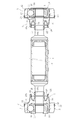
動力伝達装置としては、図5に示すように、中間のシャフト1と、シャフト1の一方の端部に連結される等速自在継手2と、シャフト1の他方の端部に連結される等速自在継手3とを備えるものがある。
シャフト1は中間の大径のシャフト本体1aと、シャフト本体1aの一方の等速自在継手2側に軸部材1bと、シャフト本体1aの他方の等速自在継手2側に軸部材1cとを備える。各軸部材1b、1cの端部にはそれぞれ雄スプライン4、5が形成されている。
この図例の等速自在継手2、3は、それぞれ、クロスグルーブ型等速自在継手であって、内周面10に軸線に対して傾斜する複数の直線状トラック溝11が形成された外側継手部材12と、外周面13に軸線に対して前記外側継手部材12のトラック溝11と反対方向に傾斜するトラック溝14が形成された内側継手部材16と、前記外側継手部材12のトラック溝11と前記内側継手部材16のトラック溝14との交叉部に組み込まれた複数のボール17と、前記外側継手部材12と前記内側継手部材16との間で前記ボール17を保持するケージ18とを備える。
各等速自在継手2、3には、シャフト側の開口部を塞ぐ密封装置Sが付設される。この場合の密封装置Sは、クロロプレンゴム(CRゴム)等からなるブーツ20と金属製のブーツアダプタ21とを備える。ブーツ20は大径端部20aと小径端部20bとを有する断面U字型の形状となっており、小径端部20bは軸部材1b(1c)の外周面に取り付けられ、この取り付け部分はブーツバンド22を介して固定されている。ブーツアダプタ21は円筒形で、一端部23は外側継手部材12の外周面に取り付けられ、また、他端部24は前記ブーツ20の大径端部20aに加締めて固定されている。
ところで、鉄鋼設備の連続鋳造設備に於いては、高温化で且つ薬剤・スケールの含まれる水蒸気の雰囲気状態である。また、熱延ラインの鋼鈑巻取り装置(ダウンコイラー)では、滝のように水がかかる雰囲気状態でロールを駆動させなければならない。製紙設備に於いては、抄紙機ラインのドライヤーロ-ル部では、高温雰囲気下でロールを駆動させなければならない。しかしながら、このような劣悪雰囲気下で前記したように密封装置Sにゴム製等のブーツを使用した場合、劣化するおそれがあった。また、ブーツの材料に耐久性向上のため熱可塑性の樹脂材料が用いられる場合もあるが、熱可塑性の樹脂材料であっても前記した劣悪雰囲気下では対応できなかった。
このため、近年においては、前記したようなブーツを使用しない金属球面シール構造のものもある(特許文献1および特許文献2)。このような球面シール構造を用いた等速自在継手は、図6に示すように、内周面に軸方向に延びる複数のトラック溝を有する外側継手部材30と、外周面に軸方向に延びる複数のトラック溝を有する内側継手部材31と、両トラック溝によって形成されたトラックに配された複数のトルク伝達ボール32と、これらボール32を円周方向等間隔に支持する保持器33とで構成されている。
この等速自在継手の外側継手部材30には、取り付けフランジ34が一体的に連結されている。等速自在継手の内側継手部材31には、取り付けフランジ35が取り付け部材36のボルト37による締結でもって一体的に取り付けられている。等速自在継手の外側継手部材30と内側継手部材31との間に、等速自在軸継手の内部からの潤滑剤の漏洩を防止する球面シール構造の密封装置40が設けられている。
この密封装置40は、凸球面部材である金属製のメカニカルシール内環41と、凹球面部材である金属製のメカニカルシール外環42と、中間部材である金属製のメカニカルシール中環43とで構成された二重の球面メカニカルシール構造を具備する。
メカニカルシール内環41は、外周に凸球面41aが部分的に形成された部材で、内側継手部材31に軸方向移動可能に外嵌され、内側継手部材31に取り付けられた受け部材44との間に弾性部材であるコイルばね45により弾性力が付与されている。
また、メカニカルシール外環42は、内周に凹球面42bが部分的に形成された部材で、前述の内側継手部材31に固着された取り付けフランジ35に軸方向移動可能に外嵌され、その取り付けフランジ35に設けられた受け部材46との間に弾性部材であるコイルばね47により弾性力が付与されている。
さらに、メカニカルシール中環43は、内周に凹球面43bが部分的に形成されると共に外周に凸球面43aが部分的に形成された部材で、外側継手部材30にボルト50により固定されて、メカニカルシール内環41とメカニカルシール外環42との間に延びるように配されている。
ゴムや樹脂ブーツでは耐え切れない劣悪環境下において、前記のような金属球面シールタイプを用いれば、ゴムや樹脂ブーツに比べて耐水・耐食性に優れる。しかしながら、等速自在継手の外表面やシャフトの外表面等の腐食や摩滅を防止することができない。
また、等速自在継手は金属部品から構成される。このため、構成部品を通じて電気を通すことになる。すなわち、電気を通すことで漏電や電食等の不具合が起こす可能性がある。そこで、従来では、図7に示すように、外側継手部材に取付られる取付フランジ58と、相手軸(図示省略)に連結される相手側フランジ51との間に絶縁構造52を介在させている。
この場合、絶縁構造52は、取付フランジ58と相手側フランジ51との間に介在される絶縁材からなる絶縁プレート55を備えたものである。また、取付フランジ58の鍔部58a及び相手側フランジ51の鍔部51aには、それぞれ、周方向に沿って所定ピッチで複数の貫通孔53,54が設けられている。
そして、取付フランジ58と相手側フランジ51との間に絶縁プレート55を介在させるとともに、相手側フランジ51の貫通孔54に絶縁構造52の一部を構成する短円筒体の絶縁材からなる絶縁ブッシュ56を嵌入した状態で、取付フランジ58側からボルト部材60を貫通孔53及び貫通孔54に嵌入された絶縁ブッシュ56に挿通し、貫通孔54から突出したボルト部材60のねじ軸端部に絶縁ワッシャー59を挟み、ナット部材57を螺着する。これにて、取付フランジ58と相手側フランジ51とが連結されることになる。
このように、漏電や電食等を防止するために、従来では絶縁構造52(絶縁プレート55、絶縁ブッシュ56、絶縁ワッシャー59)を必要としていた。このため、部品点数が増加して、組立作業工程が増加することになって、コスト高となる。
そこで、本発明は斯かる実情に鑑み、耐傷付き性、耐水性、耐腐食性の向上を図ることができ、また、絶縁機能を有し、漏電や電食を防止することが可能な等速自在継手および動力伝達装置を提供しようとするものである。
本発明の第1の等速自在継手は、継手内部を密封する密封装置を備えた等速自在継手であって、前記密封装置はブーツを使用しない金属同士の球面接触による球面シール構造であり、少なくとも外側継手部材の外周部乃至密封装置の外周部にウレタンコーティング層を設けたものである。
本発明の第1の等速自在継手によれば、密封装置がブーツを使用しない球面シール構造であるので、ゴム製ブーツや樹脂製ブーツに比べて劣悪雰囲気下であっても、耐久性がある。ここで、劣悪雰囲気下とは、例えば鉄鋼設備に於いて薬剤水やスケールを含む温水等の飛散がある劣悪環境下等である。
また、外側継手部材の外周部乃至密封装置の外周部にウレタンコーティング層を設けているので、外側継手部材の外周部乃至密封装置の外周部において、ウレタンコーティング層にて耐傷付き性、耐水性、耐腐食性の向上を図ることができる。このため、劣悪雰囲気下においても、外側継手部材の外周部乃至密封装置の外周部における腐食や摩滅を防止できる。ここで、ウレタンコーティング層は、母材表面へウレタン樹脂をコートしてなるものである。ウレタン樹脂とは、組成中にウレタン結合を繰返し持つ化合物であり、イソシアネート基を2個以上持ったポリイソシアネート化合物(O=C=N-R-N=C=O)と、水酸基を2個以上持ったポリオール化合物(HO-R'-OH)、ポリアミン(H2N-R"-NH2)、水などの活性水素(-NH2,-NH,-CONH-など)を持った化合物などと反応して得られる。(R,R',R":脂肪族、芳香族など)
コーティングとは金属等の母材表面へ樹脂をコートすることにより、耐摩耗性、防錆、非粘着等の樹脂特性を付加させる方法である。
本発明の第2の等速自在継手は、継手内部を密封する密封装置を備えた等速自在継手であって、前記密封装置はブーツを使用しない金属同士の球面接触による球面シール構造であり、外側継手部材を外径側から包囲状とするカバー部材を備え、このカバー部材の外周部にウレタンコーティング層を設けたものである。
本発明の第2の等速自在継手によれば、前記第1の等速自在継手と同様、密封装置がブーツを使用しない球面シール構造であるので、ゴム製ブーツや樹脂製ブーツに比べて劣悪雰囲気下であっても、耐久性がある。また、カバー部材の外周部にウレタンコーティング層を設けているので、カバー部材の腐食や摩滅を防止できる。
本発明の第3の等速自在継手は、継手内部を密封する密封装置を備え、取付フランジが取付られる等速自在継手であって、前記取付フランジとの接合部にウレタンコーティング層を設けたものである。
本発明の第3の等速自在継手によれば、取付フランジとの接合部にウレタンコーティング層を設けているので、この継手本体(外側継手部材と、この外側継手部材に内装される内側継手部材等で構成される内部部品とからなる)と取付フランジとの間を絶縁状態とすることができる。
ウレタンコーティング層には防錆表面処理下地が施されてなるのが好ましい。防錆表面処理としては例えばリン酸塩処理を採用できる。
本発明の動力伝達装置は、中間のシャフトと、このシャフトの両端にそれぞれ連結される等速自在継手とを備えた動力伝達装置であって、少なくともいずれか一方の等速自在継手に前記等速自在継手を用いるとともに、シャフトの外周面にウレタンコーティング層を設けたものである。
本発明の第1及び第2等速自在継手では、劣悪雰囲気下であっても、密封装置が損傷等を生じることなく継手内部の密封性を維持することができる。また、高角度における高速回転性能の向上を図ることができる。
劣悪雰囲気下においても、第1の等速自在継手では、外側継手部材の外周部乃至密封装置の外周部における腐食や摩滅を防止でき、第2の等速自在継手では、カバー部材の腐食や摩滅を防止でき、耐久性に優れた等速自在継手となる。ところで、長期の使用による摩滅等によって、各ウレタンコーティング層の肉厚が薄くなる場合がある。このような場合、肉厚が薄くなったウレタンコーティング層の上からさらにウレタンコーティングを重ねることによって、所定の肉厚のウレタンコーティング層を構成することができ、寿命の長寿化を図ることができる。
第2の等速自在継手においては、カバー部材にウレタンコーティング層を設けることによって、カバー部材の摩耗を防止し、カバー部材の寿命を延ばすことができる。このため、カバー部材の素材にSUS材等を使用する必要が無く低コスト化を図ることができる。特に、ウレタンコーティングは素地を選ばないため、カバー部材の素材に種々のものを用いることができる利点がある。また、カバー部材としては、一般には、組立てられた継手本体に外装されるものであるので、カバー部材の点検交換が容易である。このため、長期の使用による摩滅等によって、ウレタンコーティング層の肉厚が薄くなった場合においての修復作業を容易に行うことができる。
また、ウレタンコーティングは耐水性、耐食性、耐薬品性、及び耐熱性を有しているが、特に耐摩耗性に優れている。このため、ウレタンコーティング層が設けられている部位は、耐水性、耐食性、耐薬品性、耐熱性、及び耐摩耗性に優れることになり、しかも外部からの異物の衝突等による衝撃に対しても損傷を防止することができる。
第3の等速自在継手では、継手本体と取付フランジとの間を絶縁状態とすることができ、この等速自在継手を介した漏電や電食等を防止でき、耐久性に優れた等速自在継手となる。しかも、従来のような絶縁構造を必要とせず、部品点数の減少を図ることができ、組立性に優れ、低コスト化を図ることができる。
ウレタンコーティング層に防錆表面処理下地が施されているものでは、この下地によって、ウレタンコーティング層を剥離しにくくすること、ウレタンコーティング層(塗膜)に傷が付いても錆が広がらないようにすることができる。
防錆表面処理としては、リン酸マンガン処理やリン酸鉄処理等のリン酸塩処理を採用できる。すなわち、従来の公知公用の防錆表面処理を用いることができ、低コストで容易に処理することができる。なお、リン酸マンガン処理は、処理液の主成分がリン酸イオン及びマンガンイオンから構成されており、結晶性の皮膜が形成される。リン酸鉄処理は、処理液の主成分はリン酸イオンで、他のリン酸塩処理と違い非晶質の皮膜が形成される。
本発明の動力伝達装置によれば、等速自在継手が耐久性に優れ、しかも、シャフトの腐食や摩滅を防止でき、薬剤水やスケールを含む温水等の飛散がある劣悪環境で使用される動力伝達装置に最適となる。
以下本発明の実施の形態を図1~図4に基づいて説明する。
図1に本発明にかかる第1の実施形態である動力伝達装置の等速自在継手を示し、この等速自在継手は、内径面61に複数のトラック溝62が軸方向に沿って形成された外側継手部材63と、外径面64に複数のトラック溝65が軸方向に沿って形成された内側継手部材66と、外側継手部材63のトラック溝62と内側継手部材66のトラック溝65との対で形成されるボールトラックに配置される複数のトルク伝達ボール67と、外側継手部材63の内径面61と内側継手部材66の外径面64との間に介在すると共にトルク伝達ボール67を保持するケージ68を備える。
内側継手部材66の孔部の内径面には雌スプライン71が形成され、この内側継手部材66の孔部に、シャフト72の雄スプライン73が嵌入され、この雄スプライン73が内側継手部材66の雌スプライン71に嵌合する。
シャフト72は、筒体からなるシャフト本体72aと、このシャフト本体72aに連結されるシャフト端部材72bとを備える。シャフト端部材72bは、基部75と、この基部75から突設される軸部76とからなり、この軸部76の先端部に前記雄スプライン73が形成されている。基部75は、シャフト本体72aに嵌入される嵌入部75aと、鍔部75bとからなる。また、シャフト本体72aには、その開口部が大径部77とされ、この大径部77にシャフト端部材72bの嵌入部75aが嵌入される。シャフト本体72aの開口端のテーパ面と、基部75のシャフト本体側のテーパ面との間に溶接部78が形成され、シャフト本体72aとシャフト端部材72bとが連結される。
また、シャフト72のシャフト端部材72bの端面にはストッパ板80がボルト部材81を介して取付けられている。すなわち、このストッパ板80は、平板状本体80aと、平板状本体80aの外周側に配設される周方向脚部80bとからなる。ボルト部材81がシャフト端部材72bのねじ孔に螺着された状態で、周方向脚部80bが内側継手部材66の端面(反シャフト側の端面)66aに当接するともに、平板状本体80aがシャフト端部材72bの端面76aに当接する。
外側継手部材63の反シャフト側にはフランジ90が連設されている。フランジ90は、そのシャフト側の軸方向端部が、外側継手部材63の反シャフト側の開口部91に内環される。そして、溶接を介して外側継手部材63とフランジ90とが接合される。なお、図1において、92は溶接部を示している。
フランジ90の反シャフト側の軸方向端部には外鍔部90bが設けられている。この外鍔部90bには取付用の孔部93が設けられている。また、フランジ90にはシールプレート95が内装されている。すなわち、フランジ90の内径面に内鍔部96が設けられ、この内鍔部96にシールプレート95が継手外部側から当接する。この当接した状態で、内鍔部96よりも継手外部側に設けられた周方向嵌合溝に装着されるストッパ97と、内鍔部96とで挟持される。
継手の反フランジ側の開口部は密封装置Sにて塞がれている。密封装置Sは、ブーツを使用しない金属同士の球面接触による球面シール構造であり、シャフト側のシール内環100と、外側継手部材側のシール外環101と、シール内環100をシール外環101側へ押圧する弾性部材102とを備える。
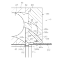
図2に示すように、シール内環100は、凸球面のシール面103を有するお碗形状の本体部100aと、本体部100aの内径部に連設される短円筒部100bとからなる。また、シール外環101は、継手外部側の内径部に内鍔部101aを有するリング体からなる。シール外環101は、外側継手部材63に螺着されるボルト部材110(図1参照)を介して外側継手部材63の端面111に固着される。シール外環101の内鍔部101aは、径方向に延びる内鍔本体105と、この内鍔本体105の内径部に継手外部から継手内部に向かって縮径する延設部106とを備える。そして、この延設部106の端面が前記シール面103に摺接する摺接面107となる。
また、シャフト72のシャフト端部材72bには、円筒状のスペーサ112が外嵌されている。このスペーサ112の継手内部側に端部には外鍔部112aが設けられている。そして、このスペーサ112にシール内環100が外嵌される。
このため、シール外環101に設けられた貫通孔113に挿入されるボルト部材110を、外側継手部材63のねじ孔114に螺着することによって、外側継手部材63にシール外環101を取付ければ、シール外環101の摺接面107がシール内環100のシール面103に圧接する状態となる。
ところで、弾性部材102はコイルスプリングからなり、シール内環100と内側継手部材66との間に介在される。この場合、シール内環100には、短円筒部100bの外径面と本体部100aの内面との間に周方向凹部115が設けられる。
このため、弾性部材102の一方の端部102aが周方向凹部115に嵌合し、他方の端部102bが内側継手部材66の端面に接触している。したがって、弾性部材102の弾性力によって、シール内環100が継手外方へ押圧される。
すなわち、等速自在継手が作動角をとった場合であっても、弾性部材102の弾性力によって、シール内環100のシール面103とシール外環101の摺接面107とが圧接するように設定される。このため、シール内環100のシール面103とシール外環101の摺接面107との間において、シール性に優れ、安定したシール機能を発揮する。
なお、シール内環100、メカニカルシール外環101は、耐腐食性に優れたSUS系材料が好適であるが、耐熱性を目的とする場合には機械構造用炭素鋼であってもよく、さらに炭素鋼に自己潤滑性のあるテフロン(登録商標)系コーティングを施すようにしてもよい。また、耐熱性に優れたSiやフッ素系ゴム等のエラストマーを適用してもよい。
この等速自在継手においては、外側継手部材63の外周部乃至密封装置Sの外周部にウレタンコーティング層を設けている。すなわち、外径側の図1の2点鎖線で示す範囲にウレタンコーティング層を設けている。具体的には、外側継手部材63とフランジ90とを接合するための溶接部92近傍から外側継手部材63の外径面およびシール外環101の外径面全体に至る範囲である。このため、外側継手部材63の外周部乃至密封装置Sの外周部において、ウレタンコーティング層にて耐傷付き性、耐水性、耐腐食性の向上を図ることができる。
ここで、ウレタンコーティング層は、母材表面へウレタン樹脂をコートしてなるものである。ウレタン樹脂とは、組成中にウレタン結合を繰返し持つ化合物であり、イソシアネート基を2個以上持ったポリイソシアネート化合物(O=C=N-R-N=C=O)と、水酸基を2個以上持ったポリオール化合物(HO-R'-OH)、ポリアミン(H2N-R"-NH2)、水などの活性水素(-NH2,-NH,-CONH-など)を持った化合物などと反応して得られる。(R,R',R":脂肪族、芳香族など)
コーティングとは金属等の母材表面へ樹脂をコートすることにより、耐摩耗性、防錆、非粘着等の樹脂特性を付加させる方法である。コーティングには、エアガン塗装、エアレスガン塗装、流動浸漬法、静電塗装法、ディッピング法等の方法がある。エアガン塗装は、水性塗料・溶剤系塗料など、比較的粘土の低い塗料をエア圧縮空気によってワークに吹き付ける方法である。エアレスガン塗装は、樹脂材質の主剤と硬化剤を定量混合し、電気式圧送(ポンプ)にて吹き付ける方法である。粘土の高い塗装に用いられ、比較的厚膜が得られる。流動浸漬法は、樹脂粉体槽へ圧縮エアを下から送り込み粉体を槽内に流動させ、加熱処理したワークを一定秒間浸漬することにより、ワークの熱で粉体を融解させ塗膜を得る方法である。静電塗装法は、高圧の直流電気を利用し、ワークの陽極(+)塗装霧化装置を陰極(-)とし、これに直流高電圧を与えて両極間に静電界を作り、霧化した塗料を負に帯電させて反対極である被塗物に効率よく塗装を吸着させる方法である。ディッピング法は、予熱したワークをゾル状の樹脂の中に浸漬し、附着させ加熱してゲル硬化させる方法である。このため、ウレタンコーティングには、エアレスガン塗装が好ましい。
ところで、シャフト端部材72bと反対側のシャフト本体72aの端部にも、このシャフト端部材72bと同様にシャフト端部材が連設され、このシャフト端部材に図1に示す等速自在継手と同様の等速自在継手が連結されている。このため、この図示省略の等速自在継手においても、外側継手部材の外周部乃至密封装置Sの外周部にウレタンコーティング層を設けている。
また、このシャフト72の外周面にもウレタンコーティング層が設けられる。この場合、図1の2点鎖線で示す範囲、すなわち、シャフト端部材72bの基部75の鍔部75bの大径部から、溶接部78、シャフト本体72a、図示省略のシャフト端部材側の溶接部、及びこの図示省略のシャフト端部材の鍔部の大径部に至る範囲である。シャフト72の外周面において、このウレタンコーティング層にて耐傷付き性、耐水性、耐腐食性の向上を図ることができる。
このように、動力伝達装置によれば、等速自在継手における密封装置Sがブーツを使用しない球面シール構造であるので、ゴム製ブーツや樹脂製ブーツに比べて劣悪雰囲気下であっても、密封装置Sには耐久性がある。しかも、シャフト72の腐食や摩滅を防止でき、薬剤水やスケールを含む温水等の飛散がある劣悪環境で使用される動力伝達装置に最適となる。また、ウレタンコーティングは耐水性、耐食性、耐薬品性、及び耐熱性を有しているが、特に耐摩耗性に優れている。このため、ウレタンコーティング層が設けられている部位は、耐水性、耐食性、耐薬品性、耐熱性、及び耐摩耗性に優れることになり、しかも外部からの異物の衝突等による衝撃に対しても損傷を防止することができる。
長期の使用による摩滅等によって、ウレタンコーティング層の肉厚が薄くなる場合がある。このような場合、肉厚が薄くなったウレタンコーティング層の上からさらにウレタンコーティングを重ねることによって、所定の肉厚のウレタンコーティング層を構成することができ、寿命の長寿化を図ることができる。
次に、図3は本発明にかかる第2の実施形態である等速自在継手を示す。この等速自在継手は、内周面に軸方向に延びる複数のトラック溝を有する外側継手部材120と、外周面に軸方向に延びる複数のトラック溝を有する内側継手部材121と、両トラック溝によって形成されたトラックに配された複数のトルク伝達ボール122と、これらボール122を円周方向等間隔に支持する保持器123とで構成されている。
この外側継手部材120には、取り付けフランジ116が溶接部108にて一体的に連結されている。内側継手部材121には、取り付けフランジ117が取り付け部材128のボルト129による締結でもって一体的に取り付けられている。外側継手部材120と内側継手部材121との間に、ブーツを使用しない金属同士の球面接触による球面シール構造の密封装置Sが設けられている。また、内側継手部材121は、トラック溝を有する内輪構成部121aと、外周面に雄スプライン118が形成された軸部121bとを備える。取り付けフランジ117は、その内径面に雄スプライン118に嵌合する雌スプライン118aが形成されている。
内側継手部材121においては、トラック溝を有する内輪構成部121aと軸部121bとの間に段差部121cがあり、この段差部121cより継手外部側においてスペーサ119が外嵌されている。内側継手部材121にフランジ117が装着された状態では、その一端面119aが段差部121cに当接しているスペーサ119の他端面119bがフランジ117の継手内部側端面117aに当接する。
この密封装置Sは、凸球面部材である金属製のメカニカルシール内環131と、凹球面部材である金属製のメカニカルシール外環132と、中間部材である金属製のメカニカルシール中環133とで構成された二重の球面メカニカルシール構造(球面シール構造)を具備する。
前述のメカニカルシール内環131は、外周に凸球面131aが部分的に形成された部材で、内側継手部材121にOリング134を介して軸方向移動可能に外嵌され、内側継手部材121に取り付けられた受け部材135との間に弾性部材であるコイルばね136により弾性力が付与されている。
また、メカニカルシール外環132は、内周に凹球面132bが部分的に形成された部材で、前述の内側継手部材121に固着された取り付けフランジ117にOリング137を介して軸方向移動可能に外嵌され、その取り付けフランジ117に設けられた受け部材138との間に弾性部材であるコイルばね139により弾性力が付与されている。
さらに、メカニカルシール中環133は、内周に凹球面133bが部分的に形成されると共に外周に凸球面133aが部分的に形成された部材で、前述の外側継手部材120にボルト140により固定されて、メカニカルシール内環131とメカニカルシール外環132との間に延びるように配されている。
メカニカルシール内環131は、その凸球面131aがOリング141を介してメカニカルシール中環133の凹球面133bと接する。内側継手部材121の受け部材135とメカニカルシール内環131との間には圧縮状態のコイルばね136が介在し、このコイルばね136の弾性力により、メカニカルシール内環131をメカニカルシール中環133に押圧して高いシール性を確保している。また、メカニカルシール内環131とメカニカルシール中環133に間にOリング141を介在させることによっても、高いシール性を確保している。
一方、メカニカルシール外環132は、その凹球面132bがOリング142を介してメカニカルシール中環133の凸球面133aと接する。取り付けフランジ117の受け部材138とメカニカルシール外環132との間には圧縮状態のコイルばね139が介在し、このコイルばね139の弾性力により、メカニカルシール外環132をメカニカルシール中環133に押圧して高いシール性を確保している。また、メカニカルシール外環132とメカニカルシール中環133に間にOリング142を介在させることによっても、高いシール性を確保している。
なお、前述したメカニカルシール内環131、メカニカルシール中環133、メカニカルシール外環132は、耐腐食性に優れたSUS系材料が好適であるが、耐熱性を目的とする場合には機械構造用炭素鋼であってもよく、さらに炭素鋼に自己潤滑性のあるテフロン(登録商標)系コーティングを施すようにしてもよい。また、耐熱性に優れたSiやフッ素系ゴム等のエラストマーを適用してもよい。Oリング134、137、141、142としては、摺動性のよいフッ素ゴム系を用いることが好ましい。
この等速自在継手は、その継手中心Oから軸方向等距離の位置に保持器123の内径中心O’と、保持器123の外径中心O'’を有するダブルオフセット構造を有する。また、継手中心Oから、メカニカルシール内環131の外周面半径およびメカニカルシール外環124の内周面半径が設定されている。
また、この等速自在継手は外側継手部材120を外径側から包囲状とするカバー部材150を備えている。カバー部材150は、例えば、SUS系材料や機械構造用炭素鋼等から構成され、円筒状の本体150aと、この本体150aのフランジ117側の開口に連設される円板状の側壁150bとからなる。この場合、カバー部材150の本体150aのフランジ116側が外側継手部材120に外嵌され、ボルト部材151を介してこの外側継手部材120にカバー部材150が固定される。この際、側壁150bがメカニカルシール外環132の軸心方向中央部に対応するまで、カバー部材150の本体150aはフランジ117側に延びる。これによって、この等速自在継手はその継手本体(外側継手部材、内側継手部材121の内輪構成部121aと、ボール122と、ケージ123等にて構成)をカバーすることができる。
また、このカバー部材150の外周部に、図1に示した等速自在継手に形成されたウレタンコーティング層と同様のウレタンコーティング層を設けている。ウレタンコーティング層を設ける範囲としては、図3の2点鎖線で示す範囲である。すなわち、フランジ116の継手本体側の端部Aからカバー部材150の側壁150bの内径端Bまでである。
図3に示す等速自在継手では、カバー部材150にウレタンコーティング層を設けることによって、カバー部材150の摩耗を防止し、カバー部材150の寿命を延ばすことができる。このため、カバー部材150の素材にSUS材等を使用する必要が無く低コスト化を図ることができる。特に、ウレタンコーティングは素地を選ばないため、カバー部材150の素材に種々のものを用いることができる利点がある。また、カバー部材150としては、組立てられた継手本体に外装されるものであるので、カバー部材150の点検交換が容易である。このため、長期の使用による摩滅等によって、ウレタンコーティング層の肉厚が薄くなった場合においての修復作業を容易に行うことができる。
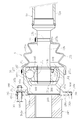
次に、図4は第3の実施形態を示し、この等速自在継手は、取付フランジ182との接合部にウレタンコーティング層を設けたものである。この場合の等速自在継手は、内径面160にトラック溝161を有する外側継手部材162と、外径面164にトラック溝165を有する内側継手部材166と、外側継手部材162のトラック溝161と内側継手部材166のトラック溝165との対で形成されるボールトラックに配置される複数のトルク伝達ボール167と、外側継手部材162の内径面160と内側継手部材166の外径面164との間に介在すると共にトルク伝達ボール167を保持するケージ168を備える。
内側継手部材166の軸心孔の内径面には雌スプライン171が設けられ、内側継手部材166の軸心孔に、シャフト72のシャフト端部材72bの雄スプライン73が嵌入され、この雄スプライン73が内側継手部材166の雌スプライン171に嵌合する。なお、シャフト端部材72bの雄スプライン73には、一対の止め輪174a,174bが装着され、これらによって抜け止めが構成される。
また、シャフト側の外側継手部材162の開口部を塞ぐ密封装置Sとしては、ブーツ175が用いられている。すなわち、ブーツ175は、大径部175aと、小径部175bと、大径部175aと小径部175bとを連結する蛇腹部175cとからなる。大径部175aが外側継手部材162の外径面の開口部側のブーツ装着部176に外嵌され、ブーツバンド177の締め付けによって外側継手部材162に固定される。また、小径部175bがシャフト72のシャフト端部材72bのブーツ装着部178に外嵌され、ブーツバンド177の締め付けによってシャフトに固定される。なお、ブーツ175はクロロプレンゴム(CRゴム)等のゴムや熱可塑性エラストマー等の樹脂からなる。
外側継手部材162の奥側小径部162aに板フランジ180が溶接を介して固着されている。すなわち、板フランジ180の内径面に周方向切欠部180a,180bが設けられ、一方の周方向切欠部180aに外側継手部材162の奥側小径部162aが嵌合される。なお、181は板フランジ180と外側継手部材162の奥側小径部162aとを連結するための溶接部である。
そして、この板フランジ180に、図示省略の相手軸(駆動軸等)を連結するためのフランジ182が連結される。フランジ182は、短円筒体からなる本体部182aと、本体部182aの板フランジ側に設けられる外鍔部182bとからなる。フランジ182の板フランジ側の端面182cには嵌合用膨出部183が設けられ、この嵌合用膨出部183が板フランジ180の他方の周方向切欠部180bに嵌合する。
板フランジ180およびフランジ182の外鍔部182bには、周方向に沿って所定ピッチで貫通孔185、186が設けられている。そして、嵌合用膨出部183を板フランジ180の他方の周方向切欠部180bに嵌合させた状態で、板フランジ180の反継手側の端面180cと、フランジ182の端面182cとを突き合わせる。この状態で、フランジ182の外鍔部182bの貫通孔186から板フランジ180の貫通孔185にボルト部材187を挿通し、貫通孔185から突出したねじ軸187bにナット部材188を螺着する。
この等速自在継手は、前記したように、取付フランジ182との接合部にウレタンコーティング層を設けたものである。この場合、クロスハッチングで示す範囲である板フランジ180の外面(端面180c、180d、外周面180e)、および板フランジ180の貫通孔185の内周面にウレタンコーティング層が設けられる。
図4に示す等速自在継手では、ウレタンコーティング層を設けることによって、継手本体(外側継手部材162と、この外側継手部材162に内装される内側継手部材166等で構成される内部部品とからなる)と取付フランジ182との間を絶縁状態とすることができる。
このため、この図4に示す等速自在継手では、この等速自在継手を介した漏電や電食等を防止でき、耐久性に優れた等速自在継手となる。しかも、従来のような絶縁構造を必要とせず、部品点数の減少を図ることができ、組立性に優れ、低コスト化を図ることができる。
ところで、前記各実施形態におけるウレタンコーティング層に防錆表面処理下地が施されてなるものであってもよい。ウレタンコーティング層に防錆表面処理下地が施されているものでは、この下地によって、ウレタンコーティング層を剥離しにくくすること、ウレタンコーティング層(塗膜)に傷が付いても錆が広がらないようにすることができる。
防錆表面処理としては、リン酸マンガン処理やリン酸鉄処理等のリン酸塩処理を採用できる。すなわち、従来の公知公用の防錆表面処理を用いることができ、低コストで容易に行うことはができる。なお、リン酸マンガン処理は、処理液の主成分がリン酸イオン及びマンガンイオンから構成されており、結晶性の皮膜が形成される。リン酸鉄処理は、処理液の主成分はリン酸イオンで、他のリン酸塩処理と違い非晶質の皮膜が形成される。
以上、本発明の実施形態につき説明したが、本発明は前記実施形態に限定されることなく種々の変形が可能であって、例えば、図1に示す等速自在継手では、トラック溝62、65が円弧部から構成されるバーフィールド型(BJ)であったが、トラック溝62、65が円弧部と直線部とからなるアンダーカットフリー型(UJ)等の固定式等速自在継手であってもよく、さらには、ダブルオフセット型(DOJ)、クロスグルーブ型(LJ)、トリポード型(TJ)などの摺動型等速自在継手にも適用可能である。
また、図3に示すようにカバー部材150を有する等速自在継手や図4に示すように絶縁構造を有する等速自在継手においても、種々の固定式等速自在継手や種々の摺動式等速自在継手であってもよい。
図4に示すように絶縁構造を有する等速自在継手においても、図1や図2に示すようなブーツを使用しない金属同士の球面接触による球面シール構造を備えたものであってもよい。
ウレタンコーティング層を形成する範囲としては、前記各実施形態のものに限るものではなく、コーティング可能な種々の範囲に設けることが可能である。また、各ウレタンコーティング層の厚さとしても、用いるコーティング方法に応じて種々設定できる。
本発明の等速自在継手や動力伝達装置は、高温化で且つ薬剤・スケールの含まれる水蒸気の雰囲気状態下で鉄鋼設備の連続鋳造設備、高温雰囲気下での製紙設備等における劣悪雰囲気下で使用可能とされる。中間のシャフトと、シャフトの一方の端部に連結される等速自在継手と、シャフトの他方の端部に連結される等速自在継手とを備える。
63、120、162 外側継手部材
66、121 166内側継手部材
72 シャフト
150 カバー部材
182 取付フランジ
66、121 166内側継手部材
72 シャフト
150 カバー部材
182 取付フランジ
Claims (6)
- 継手内部を密封する密封装置を備えた等速自在継手であって、
前記密封装置はブーツを使用しない金属同士の球面接触による球面シール構造であり、少なくとも外側継手部材の外周部乃至密封装置の外周部にウレタンコーティング層を設けたことを特徴とする等速自在継手。 - 継手内部を密封する密封装置を備えた等速自在継手であって、
前記密封装置はブーツを使用しない金属同士の球面接触による球面シール構造であり、外側継手部材を外径側から包囲状とするカバー部材を備え、このカバー部材の外周部にウレタンコーティング層を設けたことを特徴とする等速自在継手。 - 継手内部を密封する密封装置を備え、取付フランジが取付られる等速自在継手であって、
前記取付フランジとの接合部にウレタンコーティング層を設けたことを特徴とする等速自在継手。 - ウレタンコーティング層には防錆表面処理下地が施されてなることを特徴とする請求項1~請求項3のいずれか1項に記載の等速自在継手。
- 前記防錆表面処理がリン酸塩処理であることを特徴とする請求項4に記載の等速自在継手。
- 中間のシャフトと、このシャフトの両端にそれぞれ連結される等速自在継手とを備えた動力伝達装置であって、少なくともいずれか一方の等速自在継手に前記請求項1~請求項のいずれか1項に記載の等速自在継手を用いるとともに、シャフトの外周面にウレタンコーティング層を設けたことを特徴とする動力伝達装置。
Applications Claiming Priority (2)
| Application Number | Priority Date | Filing Date | Title |
|---|---|---|---|
| JP2010-057751 | 2010-03-15 | ||
| JP2010057751A JP5535700B2 (ja) | 2010-03-15 | 2010-03-15 | 等速自在継手および動力伝達装置 |
Publications (1)
| Publication Number | Publication Date |
|---|---|
| WO2011114892A1 true WO2011114892A1 (ja) | 2011-09-22 |
Family
ID=44648995
Family Applications (1)
| Application Number | Title | Priority Date | Filing Date |
|---|---|---|---|
| PCT/JP2011/054846 Ceased WO2011114892A1 (ja) | 2010-03-15 | 2011-03-03 | 等速自在継手および動力伝達装置 |
Country Status (2)
| Country | Link |
|---|---|
| JP (1) | JP5535700B2 (ja) |
| WO (1) | WO2011114892A1 (ja) |
Cited By (1)
| Publication number | Priority date | Publication date | Assignee | Title |
|---|---|---|---|---|
| CN115163681A (zh) * | 2022-06-22 | 2022-10-11 | 杭州腾励传动科技股份有限公司 | 转向管柱用万向节总成结构、万向节传动装置及汽车 |
Families Citing this family (4)
| Publication number | Priority date | Publication date | Assignee | Title |
|---|---|---|---|---|
| JP5976298B2 (ja) * | 2011-11-04 | 2016-08-23 | Ntn株式会社 | 等速自在継手 |
| WO2015088891A1 (en) * | 2013-12-13 | 2015-06-18 | Dana Automotive Systems Group, Llc | Inner race and boot sleeve |
| JP6356027B2 (ja) * | 2014-09-19 | 2018-07-11 | Ntn株式会社 | 摺動式等速自在継手 |
| JP6873626B2 (ja) * | 2016-08-19 | 2021-05-19 | Ntn株式会社 | 等速自在継手および動力伝達構造 |
Citations (4)
| Publication number | Priority date | Publication date | Assignee | Title |
|---|---|---|---|---|
| JP2004162882A (ja) * | 2002-11-15 | 2004-06-10 | Ntn Corp | 駆動力伝達装置 |
| JP2006097733A (ja) * | 2004-09-28 | 2006-04-13 | Ntn Corp | 駆動力伝達装置 |
| JP2009138908A (ja) * | 2007-12-10 | 2009-06-25 | Ntn Corp | 等速自在継手 |
| JP2009250342A (ja) * | 2008-04-04 | 2009-10-29 | Ntn Corp | 等速自在継手 |
-
2010
- 2010-03-15 JP JP2010057751A patent/JP5535700B2/ja not_active Expired - Fee Related
-
2011
- 2011-03-03 WO PCT/JP2011/054846 patent/WO2011114892A1/ja not_active Ceased
Patent Citations (4)
| Publication number | Priority date | Publication date | Assignee | Title |
|---|---|---|---|---|
| JP2004162882A (ja) * | 2002-11-15 | 2004-06-10 | Ntn Corp | 駆動力伝達装置 |
| JP2006097733A (ja) * | 2004-09-28 | 2006-04-13 | Ntn Corp | 駆動力伝達装置 |
| JP2009138908A (ja) * | 2007-12-10 | 2009-06-25 | Ntn Corp | 等速自在継手 |
| JP2009250342A (ja) * | 2008-04-04 | 2009-10-29 | Ntn Corp | 等速自在継手 |
Cited By (1)
| Publication number | Priority date | Publication date | Assignee | Title |
|---|---|---|---|---|
| CN115163681A (zh) * | 2022-06-22 | 2022-10-11 | 杭州腾励传动科技股份有限公司 | 转向管柱用万向节总成结构、万向节传动装置及汽车 |
Also Published As
| Publication number | Publication date |
|---|---|
| JP5535700B2 (ja) | 2014-07-02 |
| JP2011190871A (ja) | 2011-09-29 |
Similar Documents
| Publication | Publication Date | Title |
|---|---|---|
| JP5535700B2 (ja) | 等速自在継手および動力伝達装置 | |
| JP4248372B2 (ja) | 駆動車輪用軸受装置 | |
| US11428265B2 (en) | Plain bearing and method for its manufacture | |
| JP2007276764A (ja) | 駆動車輪用軸受装置 | |
| CN102812259B (zh) | 壳式滚针轴承及十字轴式万向接头 | |
| JP6405083B2 (ja) | 金属製自動車部品の塗膜の形成方法 | |
| UA130259C2 (uk) | Металева труба для нафтової свердловини та спосіб її виготовлення | |
| JP2009216231A (ja) | 車輪用軸受装置 | |
| US10544837B2 (en) | Constant velocity universal joint | |
| JP5901953B2 (ja) | 等速自在継手 | |
| US8398494B2 (en) | Constant velocity universal joint | |
| JP2009250342A (ja) | 等速自在継手 | |
| US20090324154A1 (en) | Wheel bearing apparatus | |
| JP2007186149A (ja) | 車輪用軸受装置 | |
| JP5760452B2 (ja) | シェル型ニードル軸受及び十字軸式自在継手 | |
| JP2014001747A (ja) | ハブユニット軸受 | |
| WO2009122855A1 (ja) | 車輪用軸受装置およびアクスルモジュール | |
| JP2009114527A (ja) | 固体潤滑被膜とその製造方法およびそれを用いた摺動部材 | |
| CN105817410A (zh) | 一种弹条防腐材料及弹条防腐处理方法 | |
| KR20070106967A (ko) | 조인트 및/또는 베어링 장치 | |
| JP2013166487A (ja) | 車輪用軸受装置 | |
| JP5252884B2 (ja) | 固体潤滑被膜とその製造方法およびそれを用いた摺動部材 | |
| JP2009008135A (ja) | 軸受ユニット | |
| RU1791090C (ru) | Способ восстановлени изношенных деталей | |
| CN117006168B (zh) | 一种具有关节十字轴的十字包及十字万向联轴器 |
Legal Events
| Date | Code | Title | Description |
|---|---|---|---|
| 121 | Ep: the epo has been informed by wipo that ep was designated in this application |
Ref document number: 11756081 Country of ref document: EP Kind code of ref document: A1 |
|
| NENP | Non-entry into the national phase |
Ref country code: DE |
|
| 122 | Ep: pct application non-entry in european phase |
Ref document number: 11756081 Country of ref document: EP Kind code of ref document: A1 |