WO2011108464A1 - 正極活物質材料、正極、2次電池及びこれらの製造方法 - Google Patents
正極活物質材料、正極、2次電池及びこれらの製造方法 Download PDFInfo
- Publication number
- WO2011108464A1 WO2011108464A1 PCT/JP2011/054350 JP2011054350W WO2011108464A1 WO 2011108464 A1 WO2011108464 A1 WO 2011108464A1 JP 2011054350 W JP2011054350 W JP 2011054350W WO 2011108464 A1 WO2011108464 A1 WO 2011108464A1
- Authority
- WO
- WIPO (PCT)
- Prior art keywords
- active material
- positive electrode
- electrode active
- transition metal
- secondary battery
- Prior art date
- Legal status (The legal status is an assumption and is not a legal conclusion. Google has not performed a legal analysis and makes no representation as to the accuracy of the status listed.)
- Ceased
Links
Images


Classifications
-
- H—ELECTRICITY
- H01—ELECTRIC ELEMENTS
- H01M—PROCESSES OR MEANS, e.g. BATTERIES, FOR THE DIRECT CONVERSION OF CHEMICAL ENERGY INTO ELECTRICAL ENERGY
- H01M4/00—Electrodes
- H01M4/02—Electrodes composed of, or comprising, active material
- H01M4/36—Selection of substances as active materials, active masses, active liquids
- H01M4/58—Selection of substances as active materials, active masses, active liquids of inorganic compounds other than oxides or hydroxides, e.g. sulfides, selenides, tellurides, halogenides or LiCoFy; of polyanionic structures, e.g. phosphates, silicates or borates
- H01M4/5825—Oxygenated metallic salts or polyanionic structures, e.g. borates, phosphates, silicates, olivines
-
- C—CHEMISTRY; METALLURGY
- C01—INORGANIC CHEMISTRY
- C01B—NON-METALLIC ELEMENTS; COMPOUNDS THEREOF; METALLOIDS OR COMPOUNDS THEREOF NOT COVERED BY SUBCLASS C01C
- C01B33/00—Silicon; Compounds thereof
- C01B33/02—Silicon
- C01B33/021—Preparation
-
- H—ELECTRICITY
- H01—ELECTRIC ELEMENTS
- H01M—PROCESSES OR MEANS, e.g. BATTERIES, FOR THE DIRECT CONVERSION OF CHEMICAL ENERGY INTO ELECTRICAL ENERGY
- H01M10/00—Secondary cells; Manufacture thereof
- H01M10/05—Accumulators with non-aqueous electrolyte
- H01M10/052—Li-accumulators
-
- Y—GENERAL TAGGING OF NEW TECHNOLOGICAL DEVELOPMENTS; GENERAL TAGGING OF CROSS-SECTIONAL TECHNOLOGIES SPANNING OVER SEVERAL SECTIONS OF THE IPC; TECHNICAL SUBJECTS COVERED BY FORMER USPC CROSS-REFERENCE ART COLLECTIONS [XRACs] AND DIGESTS
- Y02—TECHNOLOGIES OR APPLICATIONS FOR MITIGATION OR ADAPTATION AGAINST CLIMATE CHANGE
- Y02E—REDUCTION OF GREENHOUSE GAS [GHG] EMISSIONS, RELATED TO ENERGY GENERATION, TRANSMISSION OR DISTRIBUTION
- Y02E60/00—Enabling technologies; Technologies with a potential or indirect contribution to GHG emissions mitigation
- Y02E60/10—Energy storage using batteries
-
- Y—GENERAL TAGGING OF NEW TECHNOLOGICAL DEVELOPMENTS; GENERAL TAGGING OF CROSS-SECTIONAL TECHNOLOGIES SPANNING OVER SEVERAL SECTIONS OF THE IPC; TECHNICAL SUBJECTS COVERED BY FORMER USPC CROSS-REFERENCE ART COLLECTIONS [XRACs] AND DIGESTS
- Y02—TECHNOLOGIES OR APPLICATIONS FOR MITIGATION OR ADAPTATION AGAINST CLIMATE CHANGE
- Y02P—CLIMATE CHANGE MITIGATION TECHNOLOGIES IN THE PRODUCTION OR PROCESSING OF GOODS
- Y02P70/00—Climate change mitigation technologies in the production process for final industrial or consumer products
- Y02P70/50—Manufacturing or production processes characterised by the final manufactured product
-
- Y—GENERAL TAGGING OF NEW TECHNOLOGICAL DEVELOPMENTS; GENERAL TAGGING OF CROSS-SECTIONAL TECHNOLOGIES SPANNING OVER SEVERAL SECTIONS OF THE IPC; TECHNICAL SUBJECTS COVERED BY FORMER USPC CROSS-REFERENCE ART COLLECTIONS [XRACs] AND DIGESTS
- Y02—TECHNOLOGIES OR APPLICATIONS FOR MITIGATION OR ADAPTATION AGAINST CLIMATE CHANGE
- Y02T—CLIMATE CHANGE MITIGATION TECHNOLOGIES RELATED TO TRANSPORTATION
- Y02T10/00—Road transport of goods or passengers
- Y02T10/60—Other road transportation technologies with climate change mitigation effect
- Y02T10/70—Energy storage systems for electromobility, e.g. batteries
Definitions
- the present invention relates to a fine particle mixture containing an amorphous or low crystalline lithium transition metal silicate and serving as a precursor of an active material used for a positive electrode of a nonaqueous electrolyte secondary battery.
- Li-ion secondary batteries replace the conventional NiCd batteries and Ni-hydrogen batteries due to the high energy density obtained from the high voltages of the positive electrode active material and the negative electrode active material used. Occupies a position.
- a lithium ion secondary battery using a combination of a lithium cobalt oxide (LiCoO 2 ) -based positive electrode active material and a graphite-based carbon-based negative electrode active material, which is used as a standard in current Li-ion batteries The power consumption of the load electronic components cannot be sufficiently supplied, and the required performance cannot be satisfied as a portable power source.
- the theoretical electrochemical specific capacity of the positive electrode active material is generally small, manganate lithium or nickelate lithium used in addition to cobaltate lithium, or iron phosphate lithium to be studied for the next practical application Even so, the value is smaller than the theoretical specific capacity of the current carbon-based negative electrode active material.
- carbon-based negative electrode active material whose performance has been gradually improved year by year is approaching the theoretical specific capacity, and the combination of the current positive electrode and negative electrode active material systems can no longer expect a large increase in power capacity.
- the inventors of the present invention have made extensive comparisons between a positive electrode active material material that has been used conventionally and a conventional lithium transition metal silicate compound, and the conventional lithium transition metal silicate compound has a large crystal size. Even if a lithium transition metal silicate compound close to 1 is coexistent with a conductive material to impart conductivity, or a conductive material is supported or coated, it is disadvantageous for use as a Li ion intercalation host. I found out.
- the present invention has been made in view of the above-described problems, and its object is to include a positive electrode active material that includes a small particle size / low crystallinity lithium transition metal silicate and can perform a charge / discharge reaction in a room temperature environment.
- the purpose is to provide.
- the present invention provides the following inventions.
- Non-water characterized by containing a lithium transition metal silicate and having a crystallite size within a range of 5 to 50 nm obtained from diffraction results of 2 ⁇ 5 to 50 ° by powder X-ray diffraction Positive electrode active material for electrolyte secondary battery.
- the positive electrode active material according to (1) or (2) wherein the particle size distribution measured by a transmission electron microscope image is in the range of 10 to 200 nm and the average particle size is in the range of 25 to 100 nm. Material material.
- the positive electrode active material according to (1) or (2) wherein the positive electrode active material is in a microcrystalline state having a crystal at least partially covered with an amorphous component.
- the positive electrode active material according to (1) or (2) wherein the particle shape is substantially spherical.
- the transition metal of the lithium transition metal silicate contains at least two elements of Fe, Mn, Ti, Cr, V, Ni, Co, Cu, Zn, Al, Ge, Zr, Mo, and W.
- the positive electrode active material as described in (1) or (2) which is characterized.
- the positive electrode active material according to (1) or (2) wherein a part of the silicate of the lithium transition metal silicate is substituted with a metal acid, phosphoric acid or boric acid that does not release oxygen.
- It has a current collector, and a positive electrode active material layer containing the positive electrode active material material according to (1) or (2), which is formed on at least one surface of the current collector.
- the current collector is a foil containing aluminum, and at the interface between the current collector and the positive electrode active material layer, at least one of the elements constituting the current collector diffuses into the positive electrode active material layer.
- the surface roughness Rz (JIS B0601-1994 10-point average roughness) of at least the surface forming the positive electrode active material layer of the current collector is 0.5 ⁇ m or more.
- the positive electrode for nonaqueous electrolyte secondary batteries is 0.5 ⁇ m or more.
- a lithium source, a transition metal source, and a silicon source are supplied to a reaction vessel together with pure water, and a positive electrode active material is synthesized in a sealed pressure resistant environment of 150 to 400 ° C.
- An active material aggregate is produced by performing a heat treatment at 300 to 900 ° C.
- the active material aggregate is pulverized to produce a lithium transition metal silicate positive electrode active material
- a lithium source, a transition metal source, and a silicon source are supplied to a flame in a reaction vessel to synthesize an active material precursor.
- the active material precursor is further added to the active material precursor at 0.5 to 10 at 300 to 900 ° C.
- a process for producing a lithium transition metal silicate-based positive electrode active material characterized in that an active material aggregate is produced by performing heat treatment for a time, and the active material aggregate is pulverized.
- the active material aggregate is porous, and the size of voids observable from the surface of the active material aggregate is 0.01 to 0.6 ⁇ m.
- (14) or (15 ) For producing a positive electrode active material.
- (22) A non-aqueous electrolyte secondary characterized in that a slurry containing a positive electrode active material produced by the method for producing a positive electrode active material according to (14) or (15) is applied to a current collector.
- a method for producing a positive electrode for a battery is applied to a current collector.
- a positive electrode active material containing a small particle size / low crystalline lithium transition metal silicate and capable of charge / discharge reaction in a room temperature environment.
- the positive electrode active material according to the present invention when used, Li ion diffusibility and electronic conductivity of the particles of the active material itself are improved. As a result, it is possible to obtain a lithium transition metal silicate compound that facilitates deintercalation and intercalation of Li ions and can be charged and discharged even in a normal room temperature environment.
- the present invention serves as a basis for realizing the high charge / discharge capacity inherent in lithium transition metal silicate compounds in the future.
- the positive electrode active material according to the present invention has a large diffraction peak half-value width by X-ray diffraction measurement and a small crystallite size or a small particle size compared to conventional materials.
- a conductive path of ions or electrons in a single crystal or polycrystalline particle is short, ion conductivity and electron conductivity are excellent, and a barrier of charge / discharge reaction can be lowered.
- coating and carrying a conductive additive or conductive carbon improves the electrical conductivity and macro current collection up to the current collector through the conductive path network, allowing lithium to be charged and discharged even in low-temperature environments such as room temperature. Transition metal silicate compounds can be provided.
- the positive electrode active material according to the present invention is also characterized by being in a microcrystalline state having a crystal in which an amorphous component exists in a part of the periphery, as compared with a conventional positive electrode active material.
- These positive electrode active material materials cannot be obtained by a solid-phase manufacturing method that has been generally used in the past, and a method in which a raw material that is a material source of the positive electrode active material material is supplied to the same reaction system and reacted in a flame, etc. Thus, it can be obtained by generating a mainly amorphous active material precursor and then performing a heat treatment. According to such a production method, a porous active material aggregate can be easily obtained.
- a homogeneous positive electrode active material such as a substantially spherical fine particle can be obtained. Can do. This makes it possible to granulate secondary particles of a size that can be easily coated on the current collector, and has excellent adhesion between the current collector and the active material. An active material layer can be obtained.
- the component of the lithium transition metal silicate compound contained in the positive electrode active material of the present invention includes a plurality of transition metals that can obtain a two-electron reaction in the charge / discharge reaction, a higher capacity can be obtained.
- it is a silicate compound that does not release oxygen, it does not ignite and burn even in a high-temperature environment, and a safe secondary battery can be provided.
- the positive electrode active material of the present invention is provided as a powder material. Further, the positive electrode active material is a slurry of an aqueous solvent or an organic solvent in which a predetermined proportion of a dispersant, a thickener, a conductive material, or the like is added to the secondary particles that are granulated or increased in size. Also provided as Moreover, it is provided also as an electrode form which apply
- the positive electrode active material according to the present invention is synthesized by synthesizing an active material precursor or active material by supplying constituent raw materials to the same reaction system, and heat-treating it.
- the fine particle mixture as the active material precursor is synthesized by a flame method such as a flame hydrolysis method or a thermal oxidation method, and the active material is synthesized by a hydrothermal synthesis method.
- the flame method is a method of obtaining a target substance by supplying a constituent raw material into a flame and reacting the constituent raw materials by a method of supplying a raw material gas such as chloride or a method of supplying a raw material liquid through a vaporizer.
- a flame method a VAD (Vapor-phase Axial Deposition) method or the like can be cited as a suitable example.
- the flame hydrolysis method is a method in which constituent raw materials are hydrolyzed in a flame.
- an oxyhydrogen flame is generally used as a flame.
- a constituent material of the positive electrode active material is supplied to a flame supplied with hydrogen gas and oxygen gas, or a constituent material and a flame raw material (oxygen gas and hydrogen gas) are simultaneously supplied from a nozzle to synthesize a target substance.
- nanoscale ultrafine, mainly amorphous particles of the target substance can be obtained in an inert gas-filled atmosphere.
- the thermal oxidation method is a method in which constituent raw materials are thermally oxidized in a flame.
- a hydrocarbon flame is generally used as a flame, and a constituent material is supplied under the supply of a hydrocarbon gas (for example, propane gas) and an oxygen gas supply flame, or a constituent material and a flame material (for example, propane gas and oxygen).
- a hydrocarbon gas for example, propane gas
- an oxygen gas supply flame or a constituent material and a flame material (for example, propane gas and oxygen).
- propane gas for example, propane gas
- the target substance is synthesized while simultaneously supplying gas
- the constituent raw materials for obtaining the fine particle mixture of the present invention are a lithium source, a transition metal source, and a silicon source.
- gases, liquids, and solutions such as lithium chloride as a lithium source, chloride of transition metal as a transition metal source, and silicon tetrachloride as a silicon source are used.
- the raw material is solid, it is dissolved in a solvent to form a solution, which is supplied to the flame through a vaporizer.
- vaporization can be performed by increasing the vapor pressure by heating or pressure reduction and bubbling before the supply nozzle.
- lithium sources include lithium inorganic acid salts such as lithium chloride, lithium hydroxide, lithium carbonate, lithium nitrate, lithium bromide, lithium phosphate, and lithium sulfate, and lithium organic acids such as lithium oxalate, lithium acetate, and lithium naphthenate.
- a salt, a lithium alkoxide such as lithium ethoxide, an organic lithium compound such as a ⁇ -diketonate compound of lithium, lithium oxide, lithium peroxide, or the like can be used.
- Naphthenic acid is a mixture of different carboxylic acids mainly mixed with a plurality of acidic substances in petroleum, and the main component is a carboxylic acid compound of cyclopentane and cyclohexane.
- Transition metal sources include chlorides of various transition metals such as ferric chloride, manganese chloride, titanium tetrachloride, and vanadium chloride, transition metal oxalates such as iron oxalate and manganese oxalate, and transition metals such as manganese acetate.
- transition metal sulfates such as ferrous sulfate and manganese sulfate
- transition metal nitrates such as manganese nitrate
- transition metal hydroxides such as manganese oxyhydroxide and nickel hydroxide
- 2-ethylhexanoic acid Transition metal ethylhexanoate tetra (2-ethylhexyl) titanate
- iron naphthenate manganese naphthenate
- chromium naphthenate zinc naphthenate, zirconium naphthenate
- naphthene Naphthenic acid transition metal salts such as cobalt acid
- hexoate transition metal salts such as hexoate manganese
- transition Cyclopentadienyl compound of the genus titanium tetraisopropoxide (TTIP)
- TTIP titanium tetraisopropoxide
- organic metal salts of transition metals such as stearic acid, dimethyldithiocarbamic acid, acetylacetonate, oleic acid, linoleic acid, and linolenic acid, and oxides of various transition metals such as iron oxide and manganese oxide are also used depending on conditions.
- transition metals such as stearic acid, dimethyldithiocarbamic acid, acetylacetonate, oleic acid, linoleic acid, and linolenic acid
- oxides of various transition metals such as iron oxide and manganese oxide
- Silicon sources include silicon tetrachloride, octamethylcyclotetrasiloxane (OMCTS), silicon dioxide, silicon monoxide or hydrates of these silicon oxides, condensed silicic acid such as orthosilicic acid, metasilicic acid, metadisilicic acid, tetraethyl Orthosilicate (tetraethoxysilane, TEOS), tetramethylorthosilicate (tetramethoxysilane, TMOS), methyltrimethoxysilane (MTMS), methyltriethoxysilane (MTES), hexamethyldisiloxane (HMDSO), tetramethyldisiloxane (TMDSO), tetramethylcyclotetrasiloxane (TMCTS), octamethylcyclotetrasiloxane (OMCTS), octamethyltrisiloxane (OMSO), tetra-n-butoxysilane, etc
- an oxide of transition metal, a raw material of phosphoric acid, a raw material of boric acid is added as an anion source.
- the produced particulate mixture can be recovered from the exhaust gas with a filter. It can also be generated around the core rod as follows.
- a silica or silicon-based core rod (also called a seed rod) is installed in the reactor, and a lithium source, transition metal source, and silicon source are supplied together with the flame raw material into the oxyhydrogen flame or propane flame that is blown onto the core rod.
- nano-order fine particles are mainly generated and attached to the surface of the core rod.
- These generated fine particles are collected and, if necessary, filtered or sieved to remove impurities and coarse aggregates.
- the fine particle mixture thus obtained is composed of fine particles mainly having an amorphous nano-scale particle size and amorphous.
- the fine particle mixture that can be produced is amorphous and has a small particle size. Furthermore, in the flame method, a large amount of synthesis is possible in a short time compared to the conventional hydrothermal synthesis method and solid phase method, and a homogeneous fine particle mixture can be obtained at low cost.
- the fine particle mixture is mainly composed of amorphous fine particles of lithium, transition metal, silicon oxide, or lithium transition metal silicate, but in many cases, a crystalline oxide of transition metal is also mixed. Furthermore, a part of the crystalline component of the lithium transition metal silicate compound is also included.
- the diffraction peak is small and shows a wide diffraction angle, and these include fine particles with small crystallites or polycrystalline particles with small single crystals, and amorphous components around these fine particles. It appears to show diffraction originating from the crystal plane of each lithium transition metal silicate compound in microcrystalline form. Note that the peak position may shift by about ⁇ 0.1 ° to ⁇ 0.2 ° due to crystal distortion and measurement error.
- the fine particle mixture according to the present invention is a fine particle mixture comprising amorphous silicon oxide fine particles, amorphous transition metal oxide, and microcrystalline or amorphous lithium transition metal silicate fine particles. It is.
- amorphous means that the crystallite size is about 100 nm or less. The determination of whether or not it is amorphous can be obtained by applying the half width of the peak in the X-ray diffraction pattern to the Scherrer equation.
- the lithium transition metal silicate fine particles contained in the obtained fine particle mixture contain a lithium transition metal silicate compound represented by Li 2 MSiO 4 .
- M is at least one transition metal selected from the group consisting of Fe, Mn, Ti, Cr, V, Ni, Co, Cu, Zn, Al, Ge, Zr, Mo, and W.
- the pressure during the reaction in the hydrothermal synthesis method cannot be specified because it depends on the temperature, the type and amount of the input raw material, and the reaction time, but it is about 0.05 to 100 MPa.
- a part of the silicate of the lithium transition metal silicate compound is replaced by another anion, an oxide of transition metal, a raw material of phosphoric acid, and a raw material of boric acid are added as an anion source.
- the lithium source, transition metal source, and silicon source listed in the flame method can be used as the lithium source, transition metal source, and silicon source used in the hydrothermal synthesis method.
- An active material aggregate is obtained by heat-treating the fine particle mixture by the flame method or the active material by the hydrothermal synthesis method.
- the amorphous compound contained in the fine particle mixture or the active material or the mixture in the oxide form changes mainly into a lithium transition metal silicate-based crystal form compound by heat treatment.
- an organic compound which is a conductive carbon source such as polyvinyl alcohol, sucrose, or carbon black is added to the active material aggregate obtained after the heat treatment and fired again.
- a heat-treated condition is a combination of a temperature of 300 to 900 ° C. and a treatment time of 0.5 to 10 hours, and a fired product having a desired crystallinity and particle size can be obtained appropriately. Excessive heat load due to high temperature or long-time heat treatment can generate a coarse single crystal and should be avoided. Under heating conditions to obtain a desired crystalline or microcrystalline lithium transition metal silicate compound, Heat treatment conditions that can suppress the crystallite size as small as possible are desirable.
- the porous active material aggregate of the present invention shown in FIGS. 1 and 2 is obtained.
- the porous property of the porous active material aggregate and the porosity occupied by the cavities differ depending on the raw material used, particularly the type of transition metal element and the content ratio.
- a relatively large void size and porosity can be seen in the iron system, indicating a three-dimensional void and a shape and space due to the generated aggregates.
- the size of the pores in which the active material aggregate of the present invention can be observed from the surface with an electron microscope is approximately 0.01 to 0.6 ⁇ m.
- the obtained active material aggregate can be made into fine particles again by applying it to a mortar, ball mill, or other pulverizing means.
- the positive electrode active material of the invention is obtained.
- a diffraction peak is obtained in at least one of the respective ranges of 42 to 44 °. These are peaks derived from amorphous or crystalline silicon oxide, amorphous or crystalline transition metal oxide, microcrystalline, crystalline or amorphous lithium transition metal silicate.
- the crystallite size to be measured is larger as the half width of the peak by X-ray diffraction measurement is smaller, and the crystallite size is smaller as the half width is larger.
- the condition that the minimum value of the half widths of the plurality of diffraction peaks is 0.175 ° or more means that the size of the crystallite of the positive electrode active material according to the present invention is smaller than a predetermined value.
- the maximum value of the half width of a plurality of diffraction peaks is 0.6 ° or less. It is difficult to produce an excessively low crystalline lithium transition metal silicate, and if it is excessively low crystalline, the intercalation host of lithium in the crystal is reduced, and the charge / discharge capacity may be reduced. Conceivable.
- the crystallite size calculated from the diffraction result is in the range of 5 to 50 nm.
- the crystallite refers to a group that can be regarded as a single crystal, and usually one particle is composed of a plurality of crystallites. Since the size of the crystallite of the positive electrode active material according to the present invention is small, the target low-crystalline positive electrode active material can be obtained in the present invention.
- the particle size distribution of the positive electrode active material according to the present invention is measured by observation with a transmission electron microscope (TEM) to obtain the particle size distribution, it is in the range of 10 to 200 nm and the average value is in the range of 25 to 100 nm. To do. These particles are composed of a plurality of crystallites.
- the particle size distribution is more preferably in the range of 10 to 150 nm, more preferably in the range of 10 to 145 nm, and the average value is more preferably in the range of 25 to 81 nm.
- the particle size distribution in the range of 10 to 200 nm does not require the obtained particle size distribution to cover the entire range of 10 to 200 nm, and the lower limit of the obtained particle size distribution is 10 nm or more, and the upper limit is 200 nm or less. It means that there is. That is, the obtained particle size distribution may be 10 to 100 nm or 50 to 150 nm. Since the positive electrode active material according to the present invention has a small particle size, the conductive path of Li ions or electrons in single crystals or polycrystalline particles is short, and ionic conductivity and electronic conductivity are excellent. The reaction barrier can be lowered.
- the positive electrode active material according to the present invention exhibits a “microcrystalline” state having a crystal at least partially covered with an amorphous component.
- a state where particles composed of a plurality of crystallites are covered with an amorphous component or a state where crystal particles exist in an amorphous component matrix, and an amorphous component between and around the particles The state where exists.
- the positive electrode active material according to the present invention has a substantially spherical shape. Although a partially rounded portion is also recognized, the whole has a substantially spherical shape. Note that a particle having a substantially spherical shape does not mean that the particle shape is a geometrically strict spherical shape or an elliptical spherical shape, and may be partially angular or slightly protruding. It suffices if the surface of the particle is constituted by a generally smooth curved surface.
- the characteristics of the obtained positive electrode active material vary depending on the transition metal used and its type, such as charge / discharge capacity.
- synthesis is easy at a low cost, but the capacity is limited to the conventional level with only one kind of Fe.
- Mn raw material the synthesis is easy at a low cost, but lithium manganese silicate has a defect that its crystal structure tends to collapse due to Li intercalation and deintercalation, and tends to have a short charge / discharge cycle life.
- the use of two transition metals such as lithium iron manganese silicate (Li 2 Fe 1-x Mn x SiO 4 ) using two raw materials of Fe and Mn solves the problem of the low capacity and the collapse of the crystal structure. To do. Since it is difficult to obtain a high-order oxidation state depending on elements such as Fe, the use of two elements results in a two-electron reaction with Li and doubles the charge / discharge capacity. On the other hand, Fe contributes to stabilization of the crystal structure. The same can be said for Ti, Cr, V, Ni, Co, Cu, Zn, Al, Ge, Zr, Mo, and W other than Fe and Mn.
- (SiO 4 ) n silicate of an anion or polyanion is the same, and a part of (SiO 4 ) n can be substituted with another anion.
- the transition metal acid is titanic acid (TiO 4 ), chromic acid (CrO 4 ), vanadic acid (VO 4 , V 2 O 7 ), zirconic acid (ZrO 4 ), molybdic acid (MoO 4 , Mo 7 O 24 ), tungstic acid (WO 4 ), etc., or substitution with phosphoric acid (PO 4 ) or boric acid (BO 3 ).
- these anion species By substituting a part of the polysilicate ion with these anion species, it contributes to the suppression and stabilization of the crystal structure change due to repeated desorption and recovery of Li ions, and the cycle life is improved. In addition, these anionic species are less likely to release oxygen even at high temperatures, and can be used safely without causing ignition.
- a powder of a positive electrode active material coated or supported with carbon is used.
- conductive material such as carbon black if necessary, and binders such as polytetrafluoroethylene, polyvinylidene fluoride and polyimide, or dispersants such as butadiene rubber, or thickeners such as carboxymethylcellulose and cellulose derivatives.
- a mixture obtained by adding the mixture to an aqueous solvent or organic solvent to form a slurry is applied on one or both sides of a current collector such as an aluminum alloy foil containing 95% by weight or more of aluminum, and baked to obtain a solvent. Is evaporated to dryness. Thereby, the positive electrode of the present invention is obtained.
- the adhesion between the current collector and the active material, and the current collection granulation is performed by a spray dry method using the positive electrode active material and a carbon source, and firing.
- the secondary particles thus obtained can be used in the form of a slurry instead of the active material.
- the agglomerated secondary particles become large agglomerates of about 0.5 to 20 ⁇ m. This greatly improves the slurry coatability and further improves the characteristics and life of the battery electrode.
- an aqueous solvent or a non-aqueous solvent can be used as the slurry used for the spray drying method.
- the current collector surface roughness of the active material layer forming surface is Japanese Industrial Standard (JIS B 0601-1994). It is desirable that the ten-point average roughness Rz defined in (1) is 0.5 ⁇ m or more.
- the adhesiveness between the formed active material layer and the current collector is excellent, the electron conductivity accompanying the insertion and release of Li ions and the current collecting power to the current collector are increased, and the cycle life of charge / discharge is improved.
- the current collector and the active material layer formed on the current collector when a mixed state in which the main component of the current collector diffuses at least into the active material layer is shown, the current collector and the active material The interfacial bondability is improved and resistance to changes in volume and crystal structure in the charge / discharge cycle is increased, so that the cycle life is improved. It is even better when the current collector surface roughness condition is also satisfied.
- Nonaqueous electrolyte secondary battery In order to obtain a high-capacity secondary battery using the positive electrode of the present invention, various materials such as a negative electrode, an electrolytic solution, a separator, and a battery case using a conventionally known negative electrode active material can be used without any particular limitation. it can.
- the secondary battery using the positive electrode according to the present invention has a high capacity and good electrode characteristics
- a non-aqueous solvent containing fluorine is used for the electrolytic solution using the non-aqueous solvent constituting the secondary battery. If added or added, the capacity is unlikely to decrease even after repeated charging and discharging, resulting in a long life.
- the electrolyte contains fluorine, or fluorine It is desirable to use an electrolytic solution containing a nonaqueous solvent having as a substituent.
- fluorine-containing solvent relaxes the volume expansion of the silicon-based film due to alloying with Li ions during charging, particularly during the first charging process, it is possible to suppress a decrease in capacity due to charging and discharging.
- fluorine-containing non-aqueous solvent fluorinated ethylene carbonate, fluorinated chain carbonate, or the like can be used.
- Mono-tetra-fluoroethylene carbonate (4-fluoro-1,3-dioxolan-2-one, FEC) is used for fluorinated ethylene carbonate, and methyl 2,2,2-trifluoroethyl carbonate is used for fluorinated chain carbonate.
- Ethyl 2,2,2-trifluoroethyl carbonate, etc. can be used alone or in combination with a plurality of electrolytes. Since the fluorine group is easy to bond with silicon and is strong, it is considered that the film can be stabilized and contribute to suppression of expansion even when it is expanded by charging alloy with Li ion.
- the positive electrode active material for a secondary battery according to the present invention has unprecedented nanoscale small crystals and primary particles, and further, since the crystallinity is low, the distance to which Li ions and electrons move is small. Since the ionic conductivity and the electronic conductivity are excellent, a high capacity inherently possessed by the silicate lithium transition metal compound can be obtained during charging and discharging.
- the secondary battery using the positive electrode using the positive electrode active material of the present invention described above uses a lithium transition metal silicate compound having a large specific capacity and can be charged at room temperature conditions that have not been achieved in the past. Discharge can be achieved and good electrode characteristics can be obtained.
- the nonaqueous electrolyte secondary battery using the positive electrode active material according to the present invention realizes a secondary battery using a lithium transition metal silicate compound that is expected to have an unprecedented high capacity in the future. Can do.
- Such a high-capacity secondary battery can be used as a driving power source for mobile electronic devices, electric tools, electric vehicles, and the like.
- a fine particle mixture or an active material for producing a lithium transition metal silicate positive electrode active material for test evaluation was prepared as follows.
- (1-1) Synthesis Example 1
- a reaction vessel of a production apparatus for producing a fine particle mixture by a flame method is a silica core rod that generates and deposits a fine particle mixture at the center of the vessel, and is arranged around the core rod, and oxygen of the flame raw material is formed on the surface of the core rod.
- a plurality of burners for supplying hydrogen gas and raw material gas are provided, and on the other hand, an exhaust pipe for exhausting reaction products such as generated fine particles and hydrochloric acid that have not been deposited is provided.
- the types of raw materials supplied from the burner and the supply flow rate conditions were as follows.
- a mixture of fine particles such as silica fine particles, transition metal oxide fine particles such as iron oxide and manganese oxide, and fine particles of lithium iron manganese silicate compound, which are cathode active material precursors synthesized in a flame from a burner Deposited on the core rod.
- the fine particle mixture was uniformly deposited to a uniform thickness by operating the core rod that was pulled up while rotating.
- the fine particle mixture deposited on the core rod was peeled off and collected. As a precaution, it was passed through a filter to remove impurities and align the particle size.
- the obtained fine particle mixture is the fine particle mixture a.
- Example 2 Further, the fine particle mixture b was subjected to heat treatment and carbon coating under the same conditions as in Example 1 to obtain an active material aggregate, and then pulverized to obtain a positive electrode active material B.
- Example 3 and Comparative Example 1 Moreover, after mixing polyvinyl alcohol with the active material r like Example 1, it heat-processed at 650 degreeC for 4 hours, the carbon coating or the carbon carrying
- the positive electrode slurry was applied at a coating amount of 50 g / m 2 to an aluminum foil current collector having a surface roughness Rz (JIS B 0601-1994 ten-point average roughness) described in Table 2 and having a thickness of 15 ⁇ m. Dry at 30 ° C. for 30 minutes. Thereafter, it was rolled to a density of 2.0 g / cm 3 with a roll press, punched into a 2 cm 2 disk shape, and used as a positive electrode.
- Rz JIS B 0601-1994 ten-point average roughness
- Example 5 Using these positive electrodes, metallic lithium for the negative electrode, and a mixed solvent in which ethylene carbonate and diethyl carbonate were mixed at a volume ratio of 1: 1 in the electrolytic solution, LiPF 6 was dissolved at a concentration of 1M, and a lithium secondary battery was used. Produced. Further, in Example 5, a similar battery manufactured using a mixed solvent in which mono-tetra-fluoroethylene carbonate was mixed in the electrolytic solution instead of ethylene carbonate was used. The production atmosphere was a dew point of ⁇ 50 ° C. or lower. Each electrode was used by being crimped to a battery case with a current collector. A coin-type lithium secondary battery having a diameter of 25 mm and a thickness of 1.6 mm was formed using the positive electrode, the negative electrode, the electrolyte, and the separator.
- test evaluation of the positive electrode active material of the present invention was performed as follows using the above coin-type lithium secondary battery.
- the battery is charged to 4.5 V (vs. Li / Li + ) by the CC-CV method at a test temperature of 25 ° C. and a current rate of 0.01 C, and then 1.5 V by the CC method at a 0.01 C rate. Discharge was performed until the same as described above, and the initial charge / discharge capacity was measured.
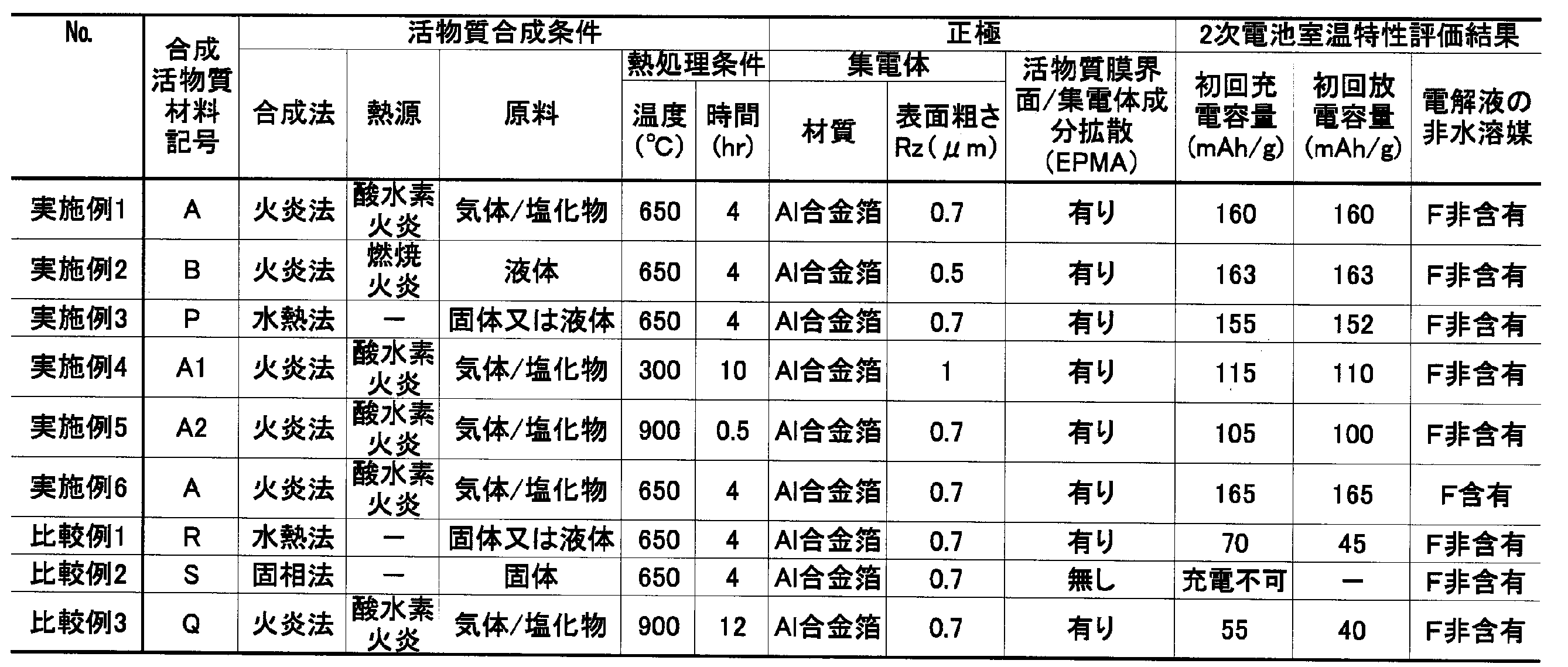
- Tables 1 and 2 show the synthesis conditions and test results of the positive electrode active material.
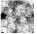
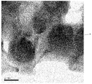
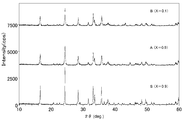
- FIGS. 1 SEM images of the active material aggregate a ′ are shown in FIGS. Further, TEM images of the positive electrode active material A are shown in FIGS. Moreover, the XRD measurement result about positive electrode active material B, A, and S is shown in FIG.
- Example 3 by the hydrothermal method has properties in a range that meets the provisions of the present invention except that the crystallinity is high and the aggregate is not obtained. Obtained. For this reason, a good capacity was also obtained in the first charge / discharge test.
- the hydrothermal synthetic particles were considered to be agglomerated due to agglomeration and exhibited a mixture exhibiting a lot of extraordinary properties. For this reason, although charge / discharge capacity was taken, it was the result which stopped in the small capacity.
- the properties show large crystal growth, and the result is that the charging process itself at room temperature is not possible.
- Example 6 using a non-aqueous solvent containing fluorine as the electrolyte solution solvent has a higher capacity than Example 1 with the same other conditions.
- Example 6 using a non-aqueous solvent containing fluorine as the electrolyte solution solvent has a higher capacity than Example 1 with the same other conditions.
- the active material aggregate a ' is agglomerated with a large number of particles having a diameter of about 50 to 200 nm with voids.
- grain is an average about 0.3 micrometer.
- the positive electrode active material A has aggregated particles having a diameter of about 50 to 100 nm.
- amorphous carbon is coated around the lithium transition metal silicate observed in black.
- the X-ray diffraction peaks of the positive electrode active material A and B synthesized by the flame method shown in FIG. 5 tend to have a wide diffraction width such as a wide half-value width. This is because the crystallite is small and the crystallite is aggregated. This is because each particle is a collection of small crystallites.
- the diffraction peak of the positive electrode active material S by solid phase synthesis is sharp and also has a large diffraction intensity, and it can be seen that it is a typical large collection of crystallites or a single crystal. The difference from materials A and B is clear.
- Examples 7 to 18 a positive electrode active material in which the type of transition metal was changed and a positive electrode active material in which a part of the silicate was replaced with another anion were the same as those in Synthesis Example 1 and Example 1. Synthesized by the method. The composition of the transition metal and anion of the positive electrode active material was determined by measuring the fine particle mixture immediately after synthesis by the flame method by ICP-AES. In addition, a positive electrode for test evaluation and a secondary battery using the obtained positive electrode active material were produced in the same manner as in Example 1. The initial discharge capacity was measured by the CC-CV method in the same manner as in Example 1, that is, at a test temperature of 25 ° C. and a current rate of 0.01 C. Table 3 shows the measurement results and test results of Examples 7 to 18.
- the temperature is high at room temperature. Has initial discharge capacity.
- a part of the silicate constituting the lithium transition metal silicate may be substituted with an anion other than silicate such as phosphoric acid or boric acid.
- the positive electrode obtained by applying the positive electrode active material of the present invention to a predetermined current collector is a rechargeable secondary battery such as a lithium ion secondary battery using a non-aqueous electrolyte. It can be used as a positive electrode exhibiting excellent charge / discharge characteristics. In the future, further improvements will serve as the basis for improving the charge / discharge capacity with the goal of the higher theoretical specific capacity inherent in the compound system of the present invention. Thereby, the characteristic which shows the high energy and the high output which are not in the past can be provided to the secondary battery for industrial use and automobile use which have been put into practical use such as conventional electronic equipment use. In addition, among the methods for producing the fine particle mixture of the present invention, the flame method is particularly excellent in mass productivity and can provide a product at low cost.
Landscapes
- Chemical & Material Sciences (AREA)
- Inorganic Chemistry (AREA)
- Chemical Kinetics & Catalysis (AREA)
- Electrochemistry (AREA)
- General Chemical & Material Sciences (AREA)
- Organic Chemistry (AREA)
- Manufacturing & Machinery (AREA)
- Engineering & Computer Science (AREA)
- Crystallography & Structural Chemistry (AREA)
- Battery Electrode And Active Subsutance (AREA)
- Cell Electrode Carriers And Collectors (AREA)
- Secondary Cells (AREA)
- Silicates, Zeolites, And Molecular Sieves (AREA)
Abstract
Description
(1)リチウム遷移金属シリケートを含み、粉末X線回折法の2θ=5~50°範囲の回折結果から得られる回折ピークの半値幅値が0.175~0.6°の範囲内であることを特徴とする非水電解質2次電池用正極活物質材料。
(2)リチウム遷移金属シリケートを含み、粉末X線回折法の2θ=5~50°範囲の回折結果から得られる結晶子の大きさが5~50nmの範囲内であることを特徴とする非水電解質2次電池用正極活物質材料。
(3)透過型電子顕微鏡像により測定した粒度分布が10~200nmの範囲に存在し、粒度平均値が25~100nmに存在することを特徴とする(1)または(2)に記載の正極活物質材料。
(4)非晶質成分で少なくとも一部が覆われた結晶を有する微結晶状態であることを特徴とする(1)または(2)に記載の正極活物質材料。
(5)粒子形状が略球形であることを特徴とする(1)または(2)に記載の正極活物質材料。
(6)少なくとも一部がカーボンコートされるか、表面の少なくとも一部にカーボンが担持されることを特徴とする(1)または(2)に記載の正極活物質材料。
(7)前記リチウム遷移金属シリケートの遷移金属が、Fe、Mn、Ti、Cr、V、Ni、Co、Cu、Zn、Al、Ge、Zr、Mo、W、のうち少なくとも2元素を含むことを特徴とする(1)または(2)に記載の正極活物質材料。
(8)
前記リチウム遷移金属シリケートのシリケートの一部を、酸素を放出しない金属酸、リン酸またはホウ酸により置換することを特徴とする(1)または(2)に記載の正極活物質材料。
(9)集電体と、前記集電体の少なくとも片面に形成された、(1)または(2)に記載の正極活物質材料を含む正極活物質層と、を有することを特徴とする非水電解質2次電池用正極。
(10)前記集電体がアルミニウムを含む箔であり、前記集電体と前記正極活物質層との界面において、前記集電体を構成する元素の少なくとも1つが前記正極活物質層へ拡散した混成界面を有していることを特徴とする(9)に記載の非水電解質2次電池用正極。
(11)前記集電体の少なくとも前記正極活物質層を形成する表面の表面粗さRz(JISB0601-1994十点平均粗さ)が0.5μm以上であることを特徴とする(10)に記載の非水電解質2次電池用正極。
(12)(9)に記載の非水電解質2次電池用正極を用いたことを特徴とする非水電解質2次電池。
(13)前記非水電解質2次電池における電解液にフッ素を含む非水溶媒を含有する電解液を用いたことを特徴とする(12)に記載の非水電解質2次電池。
(14)リチウム源、遷移金属源、シリコン源を、純水と共に反応容器へ供給して、150~400℃の密閉耐圧環境内にて、正極活物質を合成し、前記正極活物質に、さらに300~900℃で0.5~10時間の熱処理を実施することにより活物質凝集体を製造し、前記活物質凝集体を粉砕して、リチウム遷移金属シリケート系正極活物質材料を製造し、前記リチウム遷移金属シリケート系正極活物質材料は、粉末X線回折法の2θ=5~50°範囲の回折結果から得られる回折ピークの半値幅値が0.175~0.6°の範囲内である、または、粉末X線回折法の2θ=5~50°範囲の回折結果から得られる結晶子の大きさが5~50nmの範囲内であることを特徴とするリチウム遷移金属シリケート系正極活物質材料の製造方法。
(15)リチウム源、遷移金属源およびシリコン源を、反応容器中の火炎に供給して、活物質前駆体を合成し、前記活物質前駆体に、さらに300~900℃で0.5~10時間の熱処理を実施することにより活物質凝集体を製造し、前記活物質凝集体を粉砕することを特徴とするリチウム遷移金属シリケート系正極活物質材料の製造方法。
(16)前記火炎が酸水素火炎であり、前記反応容器内が不活性ガス充填雰囲気であることを特徴とする(15)に記載の正極活物質材料の製造方法。
(17)前記火炎が酸素を含む炭化水素の火炎であり、前記反応容器内が不活性ガス充填雰囲気であることを特徴とする(15)に記載の正極活物質材料の製造方法。
(18)前記火炎へ供給される前記リチウム源、前記遷移金属源および前記シリコン源が塩化物であり、前記火炎の原料が少なくとも水素ガスと酸素ガスを含むことを特徴とする(15)に記載の正極活物質材料の製造方法。
(19)前記火炎へ、前記リチウム源、前記遷移金属源および前記シリコン源を供給する際に、気体で供給する、または、液体または溶液を気化器に通して供給することを特徴とする(15)に記載の正極活物質材料の製造方法。
(20)前記活物質凝集体を製造する際に、炭素源を加えて前記熱処理を行うことを特徴とする(14)または(15)に記載の正極活物質材料の製造方法。
(21)前記活物質凝集体が多孔質であり、前記活物質凝集体の、表面から観察できる空隙の大きさが0.01~0.6μmであることを特徴とする(14)または(15)に記載の正極活物質材料の製造方法。
(22)(14)または(15)に記載の正極活物質材料の製造方法により製造された正極活物質材料を含有するスラリーを、集電体に塗布することを特徴とする非水電解質2次電池用正極の製造方法。
(23)前記スラリーが、前記正極活物質材料を加えて造粒した粒径0.5~20μmの2次粒子を含有することを特徴とする(22)に記載の非水電解質2次電池用正極の製造方法。
火炎法は、塩化物などの原料気体を供給する方法や、気化器を通して原料液体を供給する方法により、構成原料を火炎中へ供給し、構成原料を反応させ、目的物質を得る方法である。火炎法として、VAD(Vapor-phase Axial Deposition)法などが好適な例として挙げられる。
後述のように、2種以上の遷移金属をリチウム遷移金属シリケート化合物に用いる場合は、2種以上の遷移金属の原料を火炎中に供給するようにする。
また、リチウム遷移金属シリケート化合物のシリケートの一部を他のアニオンにより置換する場合は、アニオン源として、遷移金属の酸化物、リン酸の原料、ホウ酸の原料を加える
例えば、酸化チタン、亜チタン酸鉄や亜チタン酸マンガンなどの亜チタン酸金属塩、チタン酸亜鉛やチタン酸マグネシウム、チタン酸バリウムなどのチタン酸塩、酸化バナジウム、メタバナジン酸アンモニウム、酸化クロム、クロム酸塩や二クロム酸塩、酸化マンガン、過マンガン酸塩やマンガン酸塩、コバルト酸塩、酸化ジルコニウム、ジルコン酸塩、酸化モリブデン、モリブデン酸塩、酸化タングステン、タングステン酸塩、オルトリン酸やメタリン酸などのリン酸、ピロリン酸、リン酸水素2アンモニウムやリン酸2水素アンモニウムなどのリン酸水素アンモニウム塩、リン酸アンモニウム、リン酸ナトリウムなどの各種リン酸塩またはピロリン酸塩、およびリン酸第一鉄など導入遷移金属のリン酸塩、ホウ酸や三酸化二ホウ素、メタホウ酸ナトリウムや四ホウ酸ナトリウム、ホウ砂などの各種ホウ酸塩を、それぞれ所望のアニオン源と合成条件に応じて用いることができる。
微粒子混合物は、主にリチウム、遷移金属、シリコンの酸化物や、リチウム遷移金属シリケートの非晶質な微粒子からなるが、遷移金属の結晶性酸化物も混合生成している場合が多い。さらに、一部にはリチウム遷移金属シリケート系化合物の結晶成分も含まれる。これら微粒子混合物を2θ=10~50°の範囲の粉末法X線回折を測定すると、少なくとも2θ=33.1°付近と2θ=35.7°付近に回折ピークが得られる。多くの場合には、回折ピークが小さく幅の広い回折角を示し、これらは結晶子の小さい微粒子、または小さな単結晶の集まった多結晶微粒子、並びにこれら微粒子の周囲に非晶質成分が存在する微結晶形態である、それぞれのリチウム遷移金属シリケート系化合物結晶面に由来する回折を示すと思われる。なお、ピークの位置は、結晶のゆがみや測定誤差の影響で、±0.1°~±0.2°程度シフトする可能性がある。
水熱合成法は、オートクレーブなど耐圧容器内に水、リチウム源、遷移金属源、シリコン源を投入し、臨界または超臨界の中温(100~400℃程度)高圧条件を生じさせて、0.1時間~3日程度反応させることで、目的の微粒子を合成させることができる。ただし、生成粒子は凝集し易いため、2次粒子の粗大化に注意を要する。これら生成した微粒子の混合物をろ過して回収し、場合によってフィルタかふるいなどに掛けて活物質とすることができる。なお、水熱合成法での反応時の圧力は、温度・投入原料の種類と量、および反応経時によるので特定できないが、0.05~100MPa程度である。
また、リチウム遷移金属シリケート化合物のシリケートの一部を他のアニオンにより置換する場合は、アニオン源として、遷移金属の酸化物、リン酸の原料、ホウ酸の原料を加える
火炎法による微粒子混合物、または水熱合成法による活物質を熱処理することにより、活物質凝集体が得られる。また、微粒子混合物や活物質に含まれる非晶質な化合物や酸化物形態の混合物が、熱処理により主にリチウム遷移金属シリケート系の結晶形態の化合物に変化する。次いで、熱処理後の生成物の導電性を高めるために、ポリビニルアルコールやショ糖、カーボンブラックなどの導電性カーボン源である有機化合物を熱処理後得られた活物質凝集体に加えて再度焼成する。なお、微粒子混合物や活物質の最初の熱処理時に導電性カーボン源を加えて加熱処理し、結晶化と共にカーボンによるコーティングや担持処理を同一焼成工程で行うこともできる。熱処理条件は温度300~900℃と処理時間0.5~10時間の組み合わせで適宜所望の結晶性と粒径の焼成物を得ることができる。高温や長時間の熱処理による過大な熱負荷は粗大な単結晶を生成させ得るので回避すべきであり、所望の結晶性または微結晶性のリチウム遷移金属シリケート化合物が得られる程度の加熱条件で、結晶子の大きさを極力小さく抑制できる熱処理条件が望ましい。
次いで、得られた活物質凝集体を、乳鉢やボールミルほか粉砕手段に掛けることにより、再び微粒子とすることができ、例えば、図3~図4に示す、Liイオンのインターカレーションホスト足り得る本発明の正極活物質材料が得られる。
なお、複数の回折ピークの半値幅の最大値は0.6°以下であることが好ましい。過度に低結晶性のリチウム遷移金属シリケートを作成することは困難であるうえ、過度に低結晶性であると、結晶内のリチウムのインターカレーションホストが少なくなり、充放電容量が低下することが考えられる。
本発明に係る正極活物質材料は、粒子の大きさが小さいので、Liイオンまたは電子の、単結晶や多結晶粒子中の導電パスが短く、イオン導電性と電子伝導性が優れるので、充放電反応の障壁を低下させることができる。
微粒子混合物を熱処理した活物質凝集体を粉砕することにより得られた、正極活物質材料を用いて正極電極を形成するには、カーボンをコーティングしたり担持したりした正極活物質材料の粉末に、必要に応じてさらにカーボンブラックなどの導電材料を加えると共に、ポリテトラフルオロエチレンやポリフッ化ビニリデン、ポリイミドなどの結着剤、またはブタジエンゴムなどの分散剤、またはカルボキシメチルセルロースほかセルロース誘導体などの増粘剤を加えた混合物を、水系溶媒か有機溶媒中に加えてスラリーとしたものを、アルミニウムを95重量%以上含むアルミニウム合金箔などの集電体上に、片面ないしは両面に塗布し、焼成して溶媒を揮発乾固する。これにより、本発明の正極が得られる。
本発明の正極を用いた高容量な2次電池を得るには、従来公知の負極活物質材料を用いた負極や電解液、セパレータ、電池ケース等の各種材料を、特に制限なく使用することができる。
本発明の2次電池用正極活物質材料は、従来にないナノスケールの小さな結晶や1次粒子を有しており、さらに結晶性が低いためにLiイオンや電子が移動する距離が小さいために、イオン導電性や電子伝導性が優れるので、本来シリケート系リチウム遷移金属化合物が有する高い容量を充放電に際して得ることができる。
なお、以下の実施例では、リチウム鉄マンガンシリケート化合物の合成を行ったが、その他の遷移金属を用いる場合や、その他のアニオンを組成材料に加える場合でも同様に、合成、提供できる。
まず、試験評価用のリチウム遷移金属シリケート系正極活物質材料を製造するための微粒子混合物または活物質を以下のように作製した。
(1-1)合成実施例1
火炎法により微粒子混合物を製造する製造装置の反応容器は、容器の中央部に微粒子混合物を生成堆積させるシリカ製の芯棒と、芯棒の周囲に配置され、芯棒表面に火炎原料の酸素と水素ガス、および原料気体を供給する複数のバーナーを有し、他方に、堆積されなかった生成微粒子や塩酸等の反応生成物を排気する排気管を有する。バーナーから供給する原料の種類と供給流量条件は、以下とした。(組成Li2Mn1-xFexSiO4、X=0.9目標)
H2:5dm3/min、
O2:5dm3/min、
LiCl(4M水溶液):0.2dm3/min、
FeCl2・4H2O(1M水溶液):0.09dm3/min、
MnCl2・4H2O(1M水溶液):0.01dm3/min、
SiCl4:0.1dm3/min、
別途、N2ガスを所定量供給し、反応容器中を不活性ガス雰囲気とした。このような条件下で、バーナーからの火炎中で合成した正極活物質前駆体である、シリカ微粒子、酸化鉄や酸化マンガン等の遷移金属酸化物微粒子、リチウム鉄マンガンシリケート化合物の微粒子などの微粒子混合物が芯棒に堆積した。回転させながら引き上げる芯棒の操作により、均質に均一厚さに微粒子混合物を堆積させた。芯棒に堆積した微粒子混合物を剥離して収集した。念のため、不純物除去と微粒子サイズを揃えるために、フィルタに通した。得られた微粒子混合物が微粒子混合物aである。
また、同じく火炎法として、空気とプロパンガスによるプロパン燃焼火炎中へ下記の所定濃度の原料液体を供給し、熱酸化させることにより微粒子混合物bを合成して収集した。(組成Li2Mn1-xFexSiO4、X=0.1目標)
ナフテン酸リチウム(4M溶液):0.2dm3/min
C16H30FeO4(2-エチルヘキサン鉄II)(1M溶液):0.01dm3/min
C16H30MnO4(2-エチルヘキサンMnII)(1M溶液):0.09dm3/min
C8H24O4Si4(オクタメチルシクロテトラシロキサン)(1M溶液):0.1dm3/min
活物質rの作製を実施した。ポリテトラフルオロエチレン内筒製の耐圧容器に、下記の原料を投入して、オートクレーブ中で170℃、18時間の水熱合成を行った。(組成Li2Mn1-xFexSiO4、X=0.5目標)
LiOH・H2O:0.2mol、
FeCl2・4H2O:0.05mol、
MnCl2・4H2O:0.05mol、
SiO2微粒粉末:0.1mol、
別途、微量(0.01mol程)のL-アスコルビン酸を溶かしたイオン交換水を加えて、計0.5dm3とした。
室温まで冷却後、沈殿している反応生成物を回収し、充分に純水洗浄後に、これを70℃2時間真空乾燥させて、活物質rを得た。
さらに、活物質sの作製を行った。電気炉に下記の原料を混合投入後、焼成して固相法による合成を行った。(組成Li2Mn1-xFexSiO4、X=0.9目標)
Li2CO3:0.2mol、
FeC2O4・2H2O:0.09mol、
MnC2O4・2H2O:0.01mol、
SiO2微粒粉末:0.1mol、
700℃12時間の仮焼成後、1000℃24時間の本焼成を2回繰り返して、固相法合成の活物質sを得た。
(2-1)実施例1、4、5、比較例3
次に、N2ガス充填の密閉容器に、微粒子混合物aとポリビニルアルコールを所定量加えて、表1に記載の熱処理の温度と時間を変えた複数条件の加熱処理を行って、カーボンコートまたはカーボン担持を実施し、活物質凝集体a’、a1’、a2’、q’を得た。これらの活物質凝集体に粉砕処理を行い、実施例または比較例となる火炎法によるリチウム鉄マンガンシリケート系化合物正極活物質材料A、A1、A2およびQを得た。
(2-2)実施例2
また、微粒子混合物bについて、実施例1と同様の条件にて熱処理とカーボンコートを行い、活物質凝集体を得た後、粉砕処理を行い、正極活物質材料Bを得た。
(2-3)実施例3、比較例1
また、実施例1と同様に、活物質rにポリビニルアルコールを混合した後に、650℃4時間で熱処理を行い、カーボンコート又はカーボン担持処理を行って、正極活物質材料P、Rを得た。なお、正極活物質P、Rは、合成後に粒子が凝集した傾向が認められたので、Pについては乳鉢で粉砕処理を充分に行った。
(2-4)比較例2
また、実施例1と同様に、活物質sにポリビニルアルコールを加えた混合物を650℃4時間で熱処理を行い、カーボンコート又はカーボン担持処理を行って正極活物質材料Sを得た。
(3-1)粉末X線回折測定
前記の本発明実施例と比較例の微粒子混合物及び正極活物質材料の粉末X線回折測定(2θ=10~50°)を以下の測定条件で行い、合成した微粒子の結晶性や回折性と回折角2θ、正極活物質材料の結晶性と、結晶の大きさを調べた。
X線:CuKα線、出力1.2kW、測定装置:RINT2000(株式会社リガク製)
得られた活物質凝集体について、SEMにより観察した。また、微粒子混合物の熱処理後の活物質凝集体の空隙の大きさをSEM像観察により調べた。
同様に、得られた正極活物質材料について、TEMにより観察とTEM像の画像解析を行い、粒度分布(範囲と個数平均粒度)と粒子形状などを調べた。
実施例及び比較例で得た正極活物質材料粉末A、B、A1、A2、P、Q、R、Sに対して、導電助剤(カーボンブラック)を10重量%となるように混合し、内部を窒素で置換したボールミルを用いて更に5時間混合した。混合粉末と結着剤であるポリフッ化ビニリデン(PVdF)を、重量比95:5の割合で混合し、N-メチル-2-ピロリドン(NMP)を加えて十分混練し、正極スラリーを得た。
次に、前記のコイン型リチウム2次電池により、本発明の正極活物質材料の試験評価を、次のように実施した。
試験温度25℃、0.01Cの電流レートにて、CC-CV法により、4.5V(対Li/Li+)まで充電を行い、その後、0.01Cレートにて、CC法により1.5V(前記に同じ)まで放電を行って、初期の充放電容量を測定した。


A………正極活物質材料
Claims (23)
- リチウム遷移金属シリケートを含み、
粉末X線回折法の2θ=5~50°範囲の回折結果から得られる回折ピークの半値幅値が0.175~0.6°の範囲内であることを特徴とする非水電解質2次電池用正極活物質材料。 - リチウム遷移金属シリケートを含み、
粉末X線回折法の2θ=5~50°範囲の回折結果から得られる結晶子の大きさが5~50nmの範囲内であることを特徴とする非水電解質2次電池用正極活物質材料。 - 透過型電子顕微鏡像により測定した粒度分布が10~200nmの範囲に存在し、粒度平均値が25~100nmに存在することを特徴とする請求項1または請求項2に記載の正極活物質材料。
- 非晶質成分で少なくとも一部が覆われた結晶を有する微結晶状態であることを特徴とする請求項1または請求項2に記載の正極活物質材料。
- 粒子形状が略球形であることを特徴とする請求項1または請求項2に記載の正極活物質材料。
- 少なくとも一部がカーボンコートされるか、表面の少なくとも一部にカーボンが担持されることを特徴とする請求項1または請求項2に記載の正極活物質材料。
- 前記リチウム遷移金属シリケートの遷移金属が、Fe、Mn、Ti、Cr、V、Ni、Co、Cu、Zn、Al、Ge、Zr、Mo、W、のうち少なくとも2元素を含むことを特徴とする請求項1または請求項2に記載の正極活物質材料。
- 前記リチウム遷移金属シリケートのシリケートの一部を、酸素を放出しない金属酸、リン酸またはホウ酸により置換することを特徴とする請求項1または請求項2に記載の正極活物質材料。
- 集電体と、
前記集電体の少なくとも片面に形成された、請求項1または請求項2に記載の正極活物質材料を含む正極活物質層と、
を有することを特徴とする非水電解質2次電池用正極。 - 前記集電体がアルミニウムを含む箔であり、
前記集電体と前記正極活物質層との界面において、前記集電体を構成する元素の少なくとも1つが前記正極活物質層へ拡散した混成界面を有していることを特徴とする請求項9に記載の非水電解質2次電池用正極。 - 前記集電体の少なくとも前記正極活物質層を形成する表面の表面粗さRz(JIS B 0601-1994 十点平均粗さ)が0.5μm以上であることを特徴とする請求項10に記載の非水電解質2次電池用正極。
- 請求項9に記載の非水電解質2次電池用正極を用いたことを特徴とする非水電解質2次電池。
- 前記非水電解質2次電池における電解液にフッ素を含む非水溶媒を含有する電解液を用いたことを特徴とする請求項12に記載の非水電解質2次電池。
- リチウム源、遷移金属源、シリコン源を、純水と共に反応容器へ供給して、150~400℃の密閉耐圧環境内にて、正極活物質を合成し、
前記正極活物質に、さらに300~900℃で0.5~10時間の熱処理を実施することにより活物質凝集体を製造し、
前記活物質凝集体を粉砕して、リチウム遷移金属シリケート系正極活物質材料を製造し、
前記リチウム遷移金属シリケート系正極活物質材料は、
粉末X線回折法の2θ=5~50°範囲の回折結果から得られる回折ピークの半値幅値が0.175~0.6°の範囲内である、
または、粉末X線回折法の2θ=5~50°範囲の回折結果から得られる結晶子の大きさが5~50nmの範囲内である
ことを特徴とするリチウム遷移金属シリケート系正極活物質材料の製造方法。 - リチウム源、遷移金属源およびシリコン源を、反応容器中の火炎に供給して、活物質前駆体を合成し、
前記活物質前駆体に、さらに300~900℃で0.5~10時間の熱処理を実施することにより活物質凝集体を製造し、
前記活物質凝集体を粉砕する
ことを特徴とするリチウム遷移金属シリケート系正極活物質材料の製造方法。 - 前記火炎が酸水素火炎であり、
前記反応容器内が不活性ガス充填雰囲気であることを特徴とする請求項15に記載の正極活物質材料の製造方法。 - 前記火炎が酸素を含む炭化水素の火炎であり、
前記反応容器内が不活性ガス充填雰囲気であることを特徴とする請求項15に記載の正極活物質材料の製造方法。 - 前記火炎へ供給される前記リチウム源、前記遷移金属源および前記シリコン源が塩化物であり、
前記火炎の原料が少なくとも水素ガスと酸素ガスを含むことを特徴とする請求項15に記載の正極活物質材料の製造方法。 - 前記火炎へ、前記リチウム源、前記遷移金属源および前記シリコン源を供給する際に、
気体で供給する、
または、液体または溶液を気化器に通して供給することを特徴とする請求項15に記載の正極活物質材料の製造方法。 - 前記活物質凝集体を製造する際に、
炭素源を加えて前記熱処理を行うことを特徴とする請求項14または請求項15に記載の正極活物質材料の製造方法。 - 前記活物質凝集体が多孔質であり、
前記活物質凝集体の、表面から観察できる空隙の大きさが0.01~0.6μmであることを特徴とする請求項14または請求項15に記載の正極活物質材料の製造方法。 - 請求項14または請求項15に記載の正極活物質材料の製造方法により製造された正極活物質材料を含有するスラリーを、集電体に塗布する
ことを特徴とする非水電解質2次電池用正極の製造方法。 - 前記スラリーが、前記正極活物質材料を加えて造粒した粒径0.5~20μmの2次粒子を含有することを特徴とする請求項22に記載の非水電解質2次電池用正極の製造方法。
Priority Applications (3)
| Application Number | Priority Date | Filing Date | Title |
|---|---|---|---|
| CN201180011342.8A CN102770993B (zh) | 2010-03-01 | 2011-02-25 | 正极活性物质材料、正极、二次电池及其制备方法 |
| KR1020127023218A KR20130033352A (ko) | 2010-03-01 | 2011-02-25 | 정극 활물질재료, 정극, 2차 전지 및 이의 제조 방법 |
| US13/598,888 US9136535B2 (en) | 2010-03-01 | 2012-08-30 | Cathode active material, cathode, secondary battery and manufacturing methods for the same |
Applications Claiming Priority (2)
| Application Number | Priority Date | Filing Date | Title |
|---|---|---|---|
| JP2010-044185 | 2010-03-01 | ||
| JP2010044185A JP5653637B2 (ja) | 2010-03-01 | 2010-03-01 | 正極活物質材料、正極、2次電池及びこれらの製造方法 |
Related Child Applications (1)
| Application Number | Title | Priority Date | Filing Date |
|---|---|---|---|
| US13/598,888 Continuation US9136535B2 (en) | 2010-03-01 | 2012-08-30 | Cathode active material, cathode, secondary battery and manufacturing methods for the same |
Publications (1)
| Publication Number | Publication Date |
|---|---|
| WO2011108464A1 true WO2011108464A1 (ja) | 2011-09-09 |
Family
ID=44542117
Family Applications (1)
| Application Number | Title | Priority Date | Filing Date |
|---|---|---|---|
| PCT/JP2011/054350 Ceased WO2011108464A1 (ja) | 2010-03-01 | 2011-02-25 | 正極活物質材料、正極、2次電池及びこれらの製造方法 |
Country Status (6)
| Country | Link |
|---|---|
| US (1) | US9136535B2 (ja) |
| JP (1) | JP5653637B2 (ja) |
| KR (1) | KR20130033352A (ja) |
| CN (1) | CN102770993B (ja) |
| TW (1) | TWI520421B (ja) |
| WO (1) | WO2011108464A1 (ja) |
Cited By (9)
| Publication number | Priority date | Publication date | Assignee | Title |
|---|---|---|---|---|
| WO2012137703A1 (ja) * | 2011-04-07 | 2012-10-11 | 古河電気工業株式会社 | 正極活物質材料、非水電解質2次電池及び正極活物質材料の製造方法 |
| JP2013149602A (ja) * | 2011-12-21 | 2013-08-01 | Taiheiyo Cement Corp | 二次電池用正極材料の製造方法 |
| JP2014082219A (ja) * | 2014-01-30 | 2014-05-08 | Sumitomo Metal Mining Co Ltd | リチウム二次電池用正極活物質とその製造方法、および該正極活物質を用いたリチウム二次電池 |
| JP2014096345A (ja) * | 2012-10-12 | 2014-05-22 | Taiheiyo Cement Corp | 二次電池用正極材活物質の製造方法 |
| CN104335402A (zh) * | 2012-05-02 | 2015-02-04 | 海德鲁铝业钢材有限公司 | 纹理化的集电箔 |
| US20150194673A1 (en) * | 2012-08-28 | 2015-07-09 | Sumitomo Metal Mining Co., Ltd. | Method for producing positive electrode active material for nonaqueous electrolyte secondary batteries, positive electrode active material for nonaqueous electrolyte secondary batteries, and nonaqueous electrolyte secondary battery using same |
| WO2015129187A1 (ja) * | 2014-02-28 | 2015-09-03 | 三洋電機株式会社 | 非水電解質二次電池 |
| JP2016031872A (ja) * | 2014-07-30 | 2016-03-07 | 太平洋セメント株式会社 | ジルコニウム含有オリビン型正極材料及びその製造方法 |
| CN122158553A (zh) * | 2026-04-29 | 2026-06-05 | 内蒙古工业大学 | 一种Li2C2O4包覆FeTiO3阳极材料及其制备方法与应用 |
Families Citing this family (55)
| Publication number | Priority date | Publication date | Assignee | Title |
|---|---|---|---|---|
| JP5482303B2 (ja) * | 2010-03-04 | 2014-05-07 | 株式会社豊田中央研究所 | 非水系二次電池用活物質及び非水系二次電池 |
| JP5760871B2 (ja) * | 2011-09-05 | 2015-08-12 | 昭栄化学工業株式会社 | リチウムイオン二次電池用正極材料、リチウムイオン二次電池用正極部材、リチウムイオン二次電池、及びリチウムイオン二次電池用正極材料の製造方法 |
| JP5754808B2 (ja) * | 2011-10-13 | 2015-07-29 | 太平洋セメント株式会社 | 二次電池用正極活物質及びその製造方法 |
| JP5825573B2 (ja) * | 2011-10-13 | 2015-12-02 | 太平洋セメント株式会社 | リチウムイオン電池用正極活物質及びその製造法 |
| FR2982084B1 (fr) * | 2011-11-02 | 2013-11-22 | Fabien Gaben | Procede de fabrication d'electrodes de batteries entierement solides |
| WO2013084862A1 (ja) * | 2011-12-07 | 2013-06-13 | 国立大学法人東京大学 | 正極用活物質、その製造方法及びリチウムイオン二次電池 |
| JP5804419B2 (ja) * | 2011-12-14 | 2015-11-04 | 太平洋セメント株式会社 | リチウムイオン電池用正極活物質及びリチウムイオン電池 |
| JP5822197B2 (ja) * | 2011-12-16 | 2015-11-24 | 太平洋セメント株式会社 | リチウムイオン電池用正極活物質の製造方法 |
| WO2013128936A1 (ja) * | 2012-02-28 | 2013-09-06 | 株式会社豊田自動織機 | 活物質複合体及びその製造方法、非水電解質二次電池用正極活物質、並びに非水電解質二次電池 |
| JP2013196934A (ja) * | 2012-03-21 | 2013-09-30 | Furukawa Electric Co Ltd:The | 微粒子混合物の製造方法、微粒子混合物、リチウムイオン二次電池正極活物質、リチウムイオン二次電池および微粒子混合物の製造方法に用いられる水溶液 |
| TW201342697A (zh) * | 2012-03-30 | 2013-10-16 | Sumitomo Osaka Cement Co Ltd | 電極材料 |
| JP5972205B2 (ja) * | 2013-04-04 | 2016-08-17 | 古河電気工業株式会社 | 微粒子製造方法、リチウムイオン二次電池用正極活物質の製造方法、正極活物質及びこれを用いたリチウムイオン二次電池並びに微粒子製造用原料エマルション |
| CN104549930A (zh) * | 2013-10-28 | 2015-04-29 | 无锡华臻新能源科技有限公司 | 表面加入增强纤维的锂离子电池电极及涂布方式 |
| GB201409154D0 (en) | 2014-05-22 | 2014-07-09 | Faradion Ltd | Sodium transition metal silicates |
| RU2615697C1 (ru) * | 2015-12-22 | 2017-04-06 | федеральное государственное автономное образовательное учреждение высшего образования "Санкт-Петербургский политехнический университет Петра Великого" (ФГАОУ ВО "СПбПУ") | Способ получения катодного материала на основе системы Li2FeSiO4 |
| CN106129399B (zh) * | 2016-08-30 | 2019-01-29 | 中南大学 | 一种掺杂硅酸锰锂/碳复合材料及制备方法 |
| CN106252640A (zh) * | 2016-10-24 | 2016-12-21 | 上海电力学院 | 一种混合聚阴离子型硅酸锰锂正极材料及其制备方法 |
| US11495792B2 (en) | 2017-02-16 | 2022-11-08 | Global Graphene Group, Inc. | Method of manufacturing a lithium secondary battery having a protected high-capacity anode active material |
| US11978904B2 (en) | 2017-02-24 | 2024-05-07 | Honeycomb Battery Company | Polymer binder for lithium battery and method of manufacturing |
| US10840502B2 (en) | 2017-02-24 | 2020-11-17 | Global Graphene Group, Inc. | Polymer binder for lithium battery and method of manufacturing |
| US10985373B2 (en) | 2017-02-27 | 2021-04-20 | Global Graphene Group, Inc. | Lithium battery cathode and method of manufacturing |
| US11742475B2 (en) | 2017-04-03 | 2023-08-29 | Global Graphene Group, Inc. | Encapsulated anode active material particles, lithium secondary batteries containing same, and method of manufacturing |
| US10483533B2 (en) | 2017-04-10 | 2019-11-19 | Global Graphene Group, Inc. | Encapsulated cathode active material particles, lithium secondary batteries containing same, and method of manufacturing |
| US10862129B2 (en) | 2017-04-12 | 2020-12-08 | Global Graphene Group, Inc. | Lithium anode-protecting polymer layer for a lithium metal secondary battery and manufacturing method |
| US10964951B2 (en) | 2017-08-14 | 2021-03-30 | Global Graphene Group, Inc. | Anode-protecting layer for a lithium metal secondary battery and manufacturing method |
| JP6791112B2 (ja) * | 2017-12-25 | 2020-11-25 | 日亜化学工業株式会社 | 非水系二次電池用正極材料の製造方法 |
| US11721832B2 (en) | 2018-02-23 | 2023-08-08 | Global Graphene Group, Inc. | Elastomer composite-encapsulated particles of anode active materials for lithium batteries |
| US10971722B2 (en) | 2018-03-02 | 2021-04-06 | Global Graphene Group, Inc. | Method of manufacturing conducting elastomer composite-encapsulated particles of anode active materials for lithium batteries |
| US10818926B2 (en) | 2018-03-07 | 2020-10-27 | Global Graphene Group, Inc. | Method of producing electrochemically stable elastomer-encapsulated particles of anode active materials for lithium batteries |
| US11005094B2 (en) | 2018-03-07 | 2021-05-11 | Global Graphene Group, Inc. | Electrochemically stable elastomer-encapsulated particles of anode active materials for lithium batteries |
| US11043694B2 (en) | 2018-04-16 | 2021-06-22 | Global Graphene Group, Inc. | Alkali metal-selenium secondary battery containing a cathode of encapsulated selenium particles |
| FR3080957B1 (fr) | 2018-05-07 | 2020-07-10 | I-Ten | Electrodes mesoporeuses pour dispositifs electrochimiques en couches minces |
| US11121398B2 (en) | 2018-06-15 | 2021-09-14 | Global Graphene Group, Inc. | Alkali metal-sulfur secondary battery containing cathode material particulates |
| US10978744B2 (en) | 2018-06-18 | 2021-04-13 | Global Graphene Group, Inc. | Method of protecting anode of a lithium-sulfur battery |
| US10854927B2 (en) | 2018-06-18 | 2020-12-01 | Global Graphene Group, Inc. | Method of improving cycle-life of alkali metal-sulfur secondary battery |
| US10862157B2 (en) | 2018-06-18 | 2020-12-08 | Global Graphene Group, Inc. | Alkali metal-sulfur secondary battery containing a conductive electrode-protecting layer |
| US10957912B2 (en) | 2018-06-18 | 2021-03-23 | Global Graphene Group, Inc. | Method of extending cycle-life of a lithium-sulfur battery |
| US11276852B2 (en) | 2018-06-21 | 2022-03-15 | Global Graphene Group, Inc. | Lithium metal secondary battery containing an elastic anode-protecting layer |
| US12218346B2 (en) | 2018-06-21 | 2025-02-04 | Honeycomb Battery Company | Method of extending cycle-life of a lithium metal secondary battery |
| US12609344B2 (en) | 2018-06-21 | 2026-04-21 | Honeycomb Battery Company | Method of improving the cycle stability and energy density of a lithium metal secondary battery |
| US12288883B2 (en) | 2018-06-21 | 2025-04-29 | Honeycomb Battery Company | Method of improving cycle-life of a lithium metal secondary battery |
| US10873088B2 (en) | 2018-06-25 | 2020-12-22 | Global Graphene Group, Inc. | Lithium-selenium battery containing an electrode-protecting layer and method of improving cycle-life |
| US11239460B2 (en) | 2018-08-22 | 2022-02-01 | Global Graphene Group, Inc. | Method of producing electrochemically stable elastomer-encapsulated particles of cathode active materials for lithium batteries |
| US11043662B2 (en) | 2018-08-22 | 2021-06-22 | Global Graphene Group, Inc. | Electrochemically stable elastomer-encapsulated particles of cathode active materials for lithium batteries |
| US10886528B2 (en) | 2018-08-24 | 2021-01-05 | Global Graphene Group, Inc. | Protected particles of cathode active materials for lithium batteries |
| US11223049B2 (en) | 2018-08-24 | 2022-01-11 | Global Graphene Group, Inc. | Method of producing protected particles of cathode active materials for lithium batteries |
| US10971724B2 (en) | 2018-10-15 | 2021-04-06 | Global Graphene Group, Inc. | Method of producing electrochemically stable anode particulates for lithium secondary batteries |
| US12444744B2 (en) | 2018-10-15 | 2025-10-14 | Honeycomb Battery Company | Electrochemically stable anode particulates for lithium secondary batteries |
| CN109616655B (zh) * | 2018-12-17 | 2021-09-14 | 蔡杰 | 双层包覆硼酸铁锂/焦磷酸镍锂电池正极材料及制备方法 |
| FR3091036B1 (fr) | 2018-12-24 | 2024-04-19 | I Ten | Procede de fabrication de batteries, et batterie obtenue par ce procede |
| US11791450B2 (en) * | 2019-01-24 | 2023-10-17 | Global Graphene Group, Inc. | Method of improving cycle life of a rechargeable lithium metal battery |
| US10971725B2 (en) | 2019-01-24 | 2021-04-06 | Global Graphene Group, Inc. | Lithium metal secondary battery containing elastic polymer foam as an anode-protecting layer |
| JP7255276B2 (ja) * | 2019-03-25 | 2023-04-11 | トヨタ自動車株式会社 | 正極合材、全固体電池及び正極合材の製造方法 |
| US11677101B2 (en) * | 2021-01-12 | 2023-06-13 | Global Graphene Group, Inc. | High-elasticity polymer for lithium metal protection, lithium secondary battery and manufacturing method |
| KR102796339B1 (ko) * | 2022-03-25 | 2025-04-15 | 전남대학교산학협력단 | 졸-겔 방법을 이용한 리튬 디실리케이트 분말 제조방법, 그 방법으로 제조된 리튬 디실리케이트분말 및 상기 분말을 포함하는 광경화 3d 프린팅용 조성물 |
Citations (7)
| Publication number | Priority date | Publication date | Assignee | Title |
|---|---|---|---|---|
| JPH11144762A (ja) * | 1997-11-05 | 1999-05-28 | Sumitomo Electric Ind Ltd | 渦巻型リチウムイオン電池用電極およびそれを用いた渦巻型リチウムイオン電池 |
| JP2007335325A (ja) * | 2006-06-16 | 2007-12-27 | Kyushu Univ | 非水電解質二次電池用正極活物質及び電池 |
| WO2008107571A2 (fr) * | 2007-02-09 | 2008-09-12 | Centre National De La Recherche Scientifique | Silicates mixtes de lithium. |
| JP2009104794A (ja) * | 2007-10-19 | 2009-05-14 | Toyota Central R&D Labs Inc | リチウム二次電池用活物質、その製造方法及びリチウム二次電池 |
| JP2009170401A (ja) * | 2007-12-19 | 2009-07-30 | Gs Yuasa Corporation | 非水電解質二次電池 |
| WO2010089931A1 (ja) * | 2009-02-04 | 2010-08-12 | 独立行政法人産業技術総合研究所 | リチウムシリケート系化合物の製造方法 |
| JP2011076793A (ja) * | 2009-09-29 | 2011-04-14 | Furukawa Battery Co Ltd:The | オリビン型ケイ酸mリチウムの合成方法およびリチウムイオン二次電池 |
Family Cites Families (6)
| Publication number | Priority date | Publication date | Assignee | Title |
|---|---|---|---|---|
| CA2271354C (en) | 1999-05-10 | 2013-07-16 | Hydro-Quebec | Lithium insertion electrode materials based on orthosilicate derivatives |
| DE10239144A1 (de) * | 2002-08-27 | 2004-03-18 | Degussa Ag | Dispersion |
| CN101641814A (zh) * | 2007-03-27 | 2010-02-03 | 国立大学法人东京工业大学 | 二次电池用正极材料的制造方法 |
| KR101502440B1 (ko) * | 2007-07-12 | 2015-03-13 | 에이일이삼 시스템즈 인코포레이티드 | 리튬 이온 배터리용 다기능 혼합 금속 감람석 |
| JP5566723B2 (ja) * | 2010-03-01 | 2014-08-06 | 古河電気工業株式会社 | 微粒子混合物、活物質凝集体、正極活物質材料、正極、2次電池及びこれらの製造方法 |
| US9318741B2 (en) * | 2010-04-28 | 2016-04-19 | Semiconductor Energy Laboratory Co., Ltd. | Positive electrode active material of power storage device, power storage device, electrically propelled vehicle, and method for manufacturing power storage device |
-
2010
- 2010-03-01 JP JP2010044185A patent/JP5653637B2/ja active Active
-
2011
- 2011-02-25 WO PCT/JP2011/054350 patent/WO2011108464A1/ja not_active Ceased
- 2011-02-25 KR KR1020127023218A patent/KR20130033352A/ko not_active Ceased
- 2011-02-25 CN CN201180011342.8A patent/CN102770993B/zh not_active Expired - Fee Related
- 2011-03-01 TW TW100106657A patent/TWI520421B/zh not_active IP Right Cessation
-
2012
- 2012-08-30 US US13/598,888 patent/US9136535B2/en not_active Expired - Fee Related
Patent Citations (7)
| Publication number | Priority date | Publication date | Assignee | Title |
|---|---|---|---|---|
| JPH11144762A (ja) * | 1997-11-05 | 1999-05-28 | Sumitomo Electric Ind Ltd | 渦巻型リチウムイオン電池用電極およびそれを用いた渦巻型リチウムイオン電池 |
| JP2007335325A (ja) * | 2006-06-16 | 2007-12-27 | Kyushu Univ | 非水電解質二次電池用正極活物質及び電池 |
| WO2008107571A2 (fr) * | 2007-02-09 | 2008-09-12 | Centre National De La Recherche Scientifique | Silicates mixtes de lithium. |
| JP2009104794A (ja) * | 2007-10-19 | 2009-05-14 | Toyota Central R&D Labs Inc | リチウム二次電池用活物質、その製造方法及びリチウム二次電池 |
| JP2009170401A (ja) * | 2007-12-19 | 2009-07-30 | Gs Yuasa Corporation | 非水電解質二次電池 |
| WO2010089931A1 (ja) * | 2009-02-04 | 2010-08-12 | 独立行政法人産業技術総合研究所 | リチウムシリケート系化合物の製造方法 |
| JP2011076793A (ja) * | 2009-09-29 | 2011-04-14 | Furukawa Battery Co Ltd:The | オリビン型ケイ酸mリチウムの合成方法およびリチウムイオン二次電池 |
Cited By (14)
| Publication number | Priority date | Publication date | Assignee | Title |
|---|---|---|---|---|
| WO2012137703A1 (ja) * | 2011-04-07 | 2012-10-11 | 古河電気工業株式会社 | 正極活物質材料、非水電解質2次電池及び正極活物質材料の製造方法 |
| JP5950823B2 (ja) * | 2011-04-07 | 2016-07-13 | 古河電気工業株式会社 | 正極活物質材料、非水電解質2次電池及び正極活物質材料の製造方法 |
| JP2013149602A (ja) * | 2011-12-21 | 2013-08-01 | Taiheiyo Cement Corp | 二次電池用正極材料の製造方法 |
| CN104335402A (zh) * | 2012-05-02 | 2015-02-04 | 海德鲁铝业钢材有限公司 | 纹理化的集电箔 |
| US9887044B2 (en) | 2012-05-02 | 2018-02-06 | Hydro Aluminium Rolled Products Gmbh | Textured current collector foil |
| US9774036B2 (en) * | 2012-08-28 | 2017-09-26 | Sumitomo Metal Mining Co., Ltd. | Method for producing positive electrode active material for nonaqueous electrolyte secondary batteries, positive electrode active material for nonaqueous electrolyte secondary batteries, and nonaqueous electrolyte secondary battery using same |
| US20150194673A1 (en) * | 2012-08-28 | 2015-07-09 | Sumitomo Metal Mining Co., Ltd. | Method for producing positive electrode active material for nonaqueous electrolyte secondary batteries, positive electrode active material for nonaqueous electrolyte secondary batteries, and nonaqueous electrolyte secondary battery using same |
| JP2014096345A (ja) * | 2012-10-12 | 2014-05-22 | Taiheiyo Cement Corp | 二次電池用正極材活物質の製造方法 |
| JP2014082219A (ja) * | 2014-01-30 | 2014-05-08 | Sumitomo Metal Mining Co Ltd | リチウム二次電池用正極活物質とその製造方法、および該正極活物質を用いたリチウム二次電池 |
| WO2015129187A1 (ja) * | 2014-02-28 | 2015-09-03 | 三洋電機株式会社 | 非水電解質二次電池 |
| JPWO2015129187A1 (ja) * | 2014-02-28 | 2017-03-30 | 三洋電機株式会社 | 非水電解質二次電池 |
| US10340521B2 (en) | 2014-02-28 | 2019-07-02 | Sanyo Electric Co., Ltd. | Non-aqueous electrolyte secondary battery |
| JP2016031872A (ja) * | 2014-07-30 | 2016-03-07 | 太平洋セメント株式会社 | ジルコニウム含有オリビン型正極材料及びその製造方法 |
| CN122158553A (zh) * | 2026-04-29 | 2026-06-05 | 内蒙古工业大学 | 一种Li2C2O4包覆FeTiO3阳极材料及其制备方法与应用 |
Also Published As
| Publication number | Publication date |
|---|---|
| JP2011181331A (ja) | 2011-09-15 |
| CN102770993B (zh) | 2015-07-29 |
| CN102770993A (zh) | 2012-11-07 |
| US20130052544A1 (en) | 2013-02-28 |
| KR20130033352A (ko) | 2013-04-03 |
| TWI520421B (zh) | 2016-02-01 |
| TW201208186A (en) | 2012-02-16 |
| JP5653637B2 (ja) | 2015-01-14 |
| US9136535B2 (en) | 2015-09-15 |
Similar Documents
| Publication | Publication Date | Title |
|---|---|---|
| JP5653637B2 (ja) | 正極活物質材料、正極、2次電池及びこれらの製造方法 | |
| JP5566723B2 (ja) | 微粒子混合物、活物質凝集体、正極活物質材料、正極、2次電池及びこれらの製造方法 | |
| JP5950823B2 (ja) | 正極活物質材料、非水電解質2次電池及び正極活物質材料の製造方法 | |
| JP5995726B2 (ja) | 微粒子混合物、正極活物質材料、正極、2次電池及びこれらの製造方法 | |
| JP5847329B2 (ja) | 正極活物質及びその製造方法、並びに非水電解質二次電池用正極、非水電解質二次電池 | |
| JP5877112B2 (ja) | 正極活物質及びその製造方法並びに負極及び非水電解質2次電池 | |
| KR101699188B1 (ko) | 정극활물질, 비수전해질 이차전지용 정극, 비수전해질 이차전지 및 정극활물질의 제조방법 | |
| JP6046259B2 (ja) | 正極活物質、二次電池用正極、二次電池、および正極活物質の製造方法 | |
| JP5718111B2 (ja) | リチウム遷移金属シリケート系正極活物質材料及び非水電解質2次電池用正極の製造方法 | |
| JP2016197539A (ja) | リチウムイオン電池正極活物質およびその製造方法 |
Legal Events
| Date | Code | Title | Description |
|---|---|---|---|
| WWE | Wipo information: entry into national phase |
Ref document number: 201180011342.8 Country of ref document: CN |
|
| 121 | Ep: the epo has been informed by wipo that ep was designated in this application |
Ref document number: 11750574 Country of ref document: EP Kind code of ref document: A1 |
|
| NENP | Non-entry into the national phase |
Ref country code: DE |
|
| ENP | Entry into the national phase |
Ref document number: 20127023218 Country of ref document: KR Kind code of ref document: A |
|
| 122 | Ep: pct application non-entry in european phase |
Ref document number: 11750574 Country of ref document: EP Kind code of ref document: A1 |