WO2011105095A1 - バッテリモジュール、バッテリシステム、電動車両、移動体、電力貯蔵装置、電源装置および電気機器 - Google Patents
バッテリモジュール、バッテリシステム、電動車両、移動体、電力貯蔵装置、電源装置および電気機器 Download PDFInfo
- Publication number
- WO2011105095A1 WO2011105095A1 PCT/JP2011/001082 JP2011001082W WO2011105095A1 WO 2011105095 A1 WO2011105095 A1 WO 2011105095A1 JP 2011001082 W JP2011001082 W JP 2011001082W WO 2011105095 A1 WO2011105095 A1 WO 2011105095A1
- Authority
- WO
- WIPO (PCT)
- Prior art keywords
- battery
- voltage
- electrode
- bus bar
- battery module
- Prior art date
Links
Images


Classifications
-
- H—ELECTRICITY
- H01—ELECTRIC ELEMENTS
- H01M—PROCESSES OR MEANS, e.g. BATTERIES, FOR THE DIRECT CONVERSION OF CHEMICAL ENERGY INTO ELECTRICAL ENERGY
- H01M10/00—Secondary cells; Manufacture thereof
- H01M10/42—Methods or arrangements for servicing or maintenance of secondary cells or secondary half-cells
- H01M10/4207—Methods or arrangements for servicing or maintenance of secondary cells or secondary half-cells for several batteries or cells simultaneously or sequentially
-
- B—PERFORMING OPERATIONS; TRANSPORTING
- B60—VEHICLES IN GENERAL
- B60L—PROPULSION OF ELECTRICALLY-PROPELLED VEHICLES; SUPPLYING ELECTRIC POWER FOR AUXILIARY EQUIPMENT OF ELECTRICALLY-PROPELLED VEHICLES; ELECTRODYNAMIC BRAKE SYSTEMS FOR VEHICLES IN GENERAL; MAGNETIC SUSPENSION OR LEVITATION FOR VEHICLES; MONITORING OPERATING VARIABLES OF ELECTRICALLY-PROPELLED VEHICLES; ELECTRIC SAFETY DEVICES FOR ELECTRICALLY-PROPELLED VEHICLES
- B60L50/00—Electric propulsion with power supplied within the vehicle
- B60L50/50—Electric propulsion with power supplied within the vehicle using propulsion power supplied by batteries or fuel cells
- B60L50/60—Electric propulsion with power supplied within the vehicle using propulsion power supplied by batteries or fuel cells using power supplied by batteries
- B60L50/64—Constructional details of batteries specially adapted for electric vehicles
-
- H—ELECTRICITY
- H01—ELECTRIC ELEMENTS
- H01M—PROCESSES OR MEANS, e.g. BATTERIES, FOR THE DIRECT CONVERSION OF CHEMICAL ENERGY INTO ELECTRICAL ENERGY
- H01M10/00—Secondary cells; Manufacture thereof
- H01M10/42—Methods or arrangements for servicing or maintenance of secondary cells or secondary half-cells
- H01M10/425—Structural combination with electronic components, e.g. electronic circuits integrated to the outside of the casing
-
- H—ELECTRICITY
- H01—ELECTRIC ELEMENTS
- H01M—PROCESSES OR MEANS, e.g. BATTERIES, FOR THE DIRECT CONVERSION OF CHEMICAL ENERGY INTO ELECTRICAL ENERGY
- H01M10/00—Secondary cells; Manufacture thereof
- H01M10/42—Methods or arrangements for servicing or maintenance of secondary cells or secondary half-cells
- H01M10/48—Accumulators combined with arrangements for measuring, testing or indicating the condition of cells, e.g. the level or density of the electrolyte
- H01M10/482—Accumulators combined with arrangements for measuring, testing or indicating the condition of cells, e.g. the level or density of the electrolyte for several batteries or cells simultaneously or sequentially
-
- H—ELECTRICITY
- H02—GENERATION; CONVERSION OR DISTRIBUTION OF ELECTRIC POWER
- H02J—CIRCUIT ARRANGEMENTS OR SYSTEMS FOR SUPPLYING OR DISTRIBUTING ELECTRIC POWER; SYSTEMS FOR STORING ELECTRIC ENERGY
- H02J7/00—Circuit arrangements for charging or depolarising batteries or for supplying loads from batteries
- H02J7/0013—Circuit arrangements for charging or depolarising batteries or for supplying loads from batteries acting upon several batteries simultaneously or sequentially
- H02J7/0014—Circuits for equalisation of charge between batteries
- H02J7/0016—Circuits for equalisation of charge between batteries using shunting, discharge or bypass circuits
-
- G—PHYSICS
- G01—MEASURING; TESTING
- G01R—MEASURING ELECTRIC VARIABLES; MEASURING MAGNETIC VARIABLES
- G01R1/00—Details of instruments or arrangements of the types included in groups G01R5/00 - G01R13/00 and G01R31/00
- G01R1/20—Modifications of basic electric elements for use in electric measuring instruments; Structural combinations of such elements with such instruments
- G01R1/203—Resistors used for electric measuring, e.g. decade resistors standards, resistors for comparators, series resistors, shunts
-
- G—PHYSICS
- G01—MEASURING; TESTING
- G01R—MEASURING ELECTRIC VARIABLES; MEASURING MAGNETIC VARIABLES
- G01R31/00—Arrangements for testing electric properties; Arrangements for locating electric faults; Arrangements for electrical testing characterised by what is being tested not provided for elsewhere
- G01R31/36—Arrangements for testing, measuring or monitoring the electrical condition of accumulators or electric batteries, e.g. capacity or state of charge [SoC]
- G01R31/382—Arrangements for monitoring battery or accumulator variables, e.g. SoC
- G01R31/3842—Arrangements for monitoring battery or accumulator variables, e.g. SoC combining voltage and current measurements
-
- G—PHYSICS
- G01—MEASURING; TESTING
- G01R—MEASURING ELECTRIC VARIABLES; MEASURING MAGNETIC VARIABLES
- G01R31/00—Arrangements for testing electric properties; Arrangements for locating electric faults; Arrangements for electrical testing characterised by what is being tested not provided for elsewhere
- G01R31/36—Arrangements for testing, measuring or monitoring the electrical condition of accumulators or electric batteries, e.g. capacity or state of charge [SoC]
- G01R31/396—Acquisition or processing of data for testing or for monitoring individual cells or groups of cells within a battery
-
- H—ELECTRICITY
- H01—ELECTRIC ELEMENTS
- H01M—PROCESSES OR MEANS, e.g. BATTERIES, FOR THE DIRECT CONVERSION OF CHEMICAL ENERGY INTO ELECTRICAL ENERGY
- H01M10/00—Secondary cells; Manufacture thereof
- H01M10/60—Heating or cooling; Temperature control
- H01M10/61—Types of temperature control
- H01M10/613—Cooling or keeping cold
-
- H—ELECTRICITY
- H01—ELECTRIC ELEMENTS
- H01M—PROCESSES OR MEANS, e.g. BATTERIES, FOR THE DIRECT CONVERSION OF CHEMICAL ENERGY INTO ELECTRICAL ENERGY
- H01M10/00—Secondary cells; Manufacture thereof
- H01M10/60—Heating or cooling; Temperature control
- H01M10/62—Heating or cooling; Temperature control specially adapted for specific applications
- H01M10/625—Vehicles
-
- H—ELECTRICITY
- H01—ELECTRIC ELEMENTS
- H01M—PROCESSES OR MEANS, e.g. BATTERIES, FOR THE DIRECT CONVERSION OF CHEMICAL ENERGY INTO ELECTRICAL ENERGY
- H01M10/00—Secondary cells; Manufacture thereof
- H01M10/60—Heating or cooling; Temperature control
- H01M10/64—Heating or cooling; Temperature control characterised by the shape of the cells
- H01M10/647—Prismatic or flat cells, e.g. pouch cells
-
- H—ELECTRICITY
- H01—ELECTRIC ELEMENTS
- H01M—PROCESSES OR MEANS, e.g. BATTERIES, FOR THE DIRECT CONVERSION OF CHEMICAL ENERGY INTO ELECTRICAL ENERGY
- H01M10/00—Secondary cells; Manufacture thereof
- H01M10/60—Heating or cooling; Temperature control
- H01M10/65—Means for temperature control structurally associated with the cells
- H01M10/655—Solid structures for heat exchange or heat conduction
- H01M10/6551—Surfaces specially adapted for heat dissipation or radiation, e.g. fins or coatings
-
- H—ELECTRICITY
- H01—ELECTRIC ELEMENTS
- H01M—PROCESSES OR MEANS, e.g. BATTERIES, FOR THE DIRECT CONVERSION OF CHEMICAL ENERGY INTO ELECTRICAL ENERGY
- H01M10/00—Secondary cells; Manufacture thereof
- H01M10/60—Heating or cooling; Temperature control
- H01M10/65—Means for temperature control structurally associated with the cells
- H01M10/655—Solid structures for heat exchange or heat conduction
- H01M10/6556—Solid parts with flow channel passages or pipes for heat exchange
-
- H—ELECTRICITY
- H01—ELECTRIC ELEMENTS
- H01M—PROCESSES OR MEANS, e.g. BATTERIES, FOR THE DIRECT CONVERSION OF CHEMICAL ENERGY INTO ELECTRICAL ENERGY
- H01M10/00—Secondary cells; Manufacture thereof
- H01M10/60—Heating or cooling; Temperature control
- H01M10/65—Means for temperature control structurally associated with the cells
- H01M10/656—Means for temperature control structurally associated with the cells characterised by the type of heat-exchange fluid
- H01M10/6561—Gases
- H01M10/6563—Gases with forced flow, e.g. by blowers
-
- H—ELECTRICITY
- H01—ELECTRIC ELEMENTS
- H01M—PROCESSES OR MEANS, e.g. BATTERIES, FOR THE DIRECT CONVERSION OF CHEMICAL ENERGY INTO ELECTRICAL ENERGY
- H01M2200/00—Safety devices for primary or secondary batteries
- H01M2200/10—Temperature sensitive devices
- H01M2200/108—Normal resistors
-
- H—ELECTRICITY
- H01—ELECTRIC ELEMENTS
- H01M—PROCESSES OR MEANS, e.g. BATTERIES, FOR THE DIRECT CONVERSION OF CHEMICAL ENERGY INTO ELECTRICAL ENERGY
- H01M2200/00—Safety devices for primary or secondary batteries
- H01M2200/20—Pressure-sensitive devices
-
- H—ELECTRICITY
- H01—ELECTRIC ELEMENTS
- H01M—PROCESSES OR MEANS, e.g. BATTERIES, FOR THE DIRECT CONVERSION OF CHEMICAL ENERGY INTO ELECTRICAL ENERGY
- H01M50/00—Constructional details or processes of manufacture of the non-active parts of electrochemical cells other than fuel cells, e.g. hybrid cells
- H01M50/50—Current conducting connections for cells or batteries
- H01M50/502—Interconnectors for connecting terminals of adjacent batteries; Interconnectors for connecting cells outside a battery casing
- H01M50/507—Interconnectors for connecting terminals of adjacent batteries; Interconnectors for connecting cells outside a battery casing comprising an arrangement of two or more busbars within a container structure, e.g. busbar modules
-
- H—ELECTRICITY
- H01—ELECTRIC ELEMENTS
- H01M—PROCESSES OR MEANS, e.g. BATTERIES, FOR THE DIRECT CONVERSION OF CHEMICAL ENERGY INTO ELECTRICAL ENERGY
- H01M50/00—Constructional details or processes of manufacture of the non-active parts of electrochemical cells other than fuel cells, e.g. hybrid cells
- H01M50/50—Current conducting connections for cells or batteries
- H01M50/502—Interconnectors for connecting terminals of adjacent batteries; Interconnectors for connecting cells outside a battery casing
- H01M50/514—Methods for interconnecting adjacent batteries or cells
- H01M50/516—Methods for interconnecting adjacent batteries or cells by welding, soldering or brazing
-
- H—ELECTRICITY
- H01—ELECTRIC ELEMENTS
- H01M—PROCESSES OR MEANS, e.g. BATTERIES, FOR THE DIRECT CONVERSION OF CHEMICAL ENERGY INTO ELECTRICAL ENERGY
- H01M50/00—Constructional details or processes of manufacture of the non-active parts of electrochemical cells other than fuel cells, e.g. hybrid cells
- H01M50/50—Current conducting connections for cells or batteries
- H01M50/502—Interconnectors for connecting terminals of adjacent batteries; Interconnectors for connecting cells outside a battery casing
- H01M50/519—Interconnectors for connecting terminals of adjacent batteries; Interconnectors for connecting cells outside a battery casing comprising printed circuit boards [PCB]
-
- H—ELECTRICITY
- H01—ELECTRIC ELEMENTS
- H01M—PROCESSES OR MEANS, e.g. BATTERIES, FOR THE DIRECT CONVERSION OF CHEMICAL ENERGY INTO ELECTRICAL ENERGY
- H01M50/00—Constructional details or processes of manufacture of the non-active parts of electrochemical cells other than fuel cells, e.g. hybrid cells
- H01M50/50—Current conducting connections for cells or batteries
- H01M50/502—Interconnectors for connecting terminals of adjacent batteries; Interconnectors for connecting cells outside a battery casing
- H01M50/521—Interconnectors for connecting terminals of adjacent batteries; Interconnectors for connecting cells outside a battery casing characterised by the material
- H01M50/522—Inorganic material
-
- Y—GENERAL TAGGING OF NEW TECHNOLOGICAL DEVELOPMENTS; GENERAL TAGGING OF CROSS-SECTIONAL TECHNOLOGIES SPANNING OVER SEVERAL SECTIONS OF THE IPC; TECHNICAL SUBJECTS COVERED BY FORMER USPC CROSS-REFERENCE ART COLLECTIONS [XRACs] AND DIGESTS
- Y02—TECHNOLOGIES OR APPLICATIONS FOR MITIGATION OR ADAPTATION AGAINST CLIMATE CHANGE
- Y02E—REDUCTION OF GREENHOUSE GAS [GHG] EMISSIONS, RELATED TO ENERGY GENERATION, TRANSMISSION OR DISTRIBUTION
- Y02E60/00—Enabling technologies; Technologies with a potential or indirect contribution to GHG emissions mitigation
- Y02E60/10—Energy storage using batteries
-
- Y—GENERAL TAGGING OF NEW TECHNOLOGICAL DEVELOPMENTS; GENERAL TAGGING OF CROSS-SECTIONAL TECHNOLOGIES SPANNING OVER SEVERAL SECTIONS OF THE IPC; TECHNICAL SUBJECTS COVERED BY FORMER USPC CROSS-REFERENCE ART COLLECTIONS [XRACs] AND DIGESTS
- Y02—TECHNOLOGIES OR APPLICATIONS FOR MITIGATION OR ADAPTATION AGAINST CLIMATE CHANGE
- Y02T—CLIMATE CHANGE MITIGATION TECHNOLOGIES RELATED TO TRANSPORTATION
- Y02T10/00—Road transport of goods or passengers
- Y02T10/60—Other road transportation technologies with climate change mitigation effect
- Y02T10/70—Energy storage systems for electromobility, e.g. batteries
Definitions
- the present invention relates to a battery module, a battery system including the battery module, an electric vehicle, a moving body, a power storage device, a power supply device, and an electric device.
- a chargeable / dischargeable battery module is used as a drive source for a moving body such as an electric vehicle.
- a battery module has a configuration in which, for example, a plurality of batteries (battery cells) are connected in series.
- a user of a mobile object including a battery module needs to grasp the remaining capacity (charge amount) of the battery capacity of the battery module. Moreover, when charging / discharging the battery module, it is necessary to prevent overcharge and overdischarge of each battery constituting the battery module. Therefore, an apparatus for monitoring the state of the battery module has been proposed (see, for example, Patent Document 1). JP-A-8-162171
- An object of the present invention is to provide a battery module capable of detecting currents flowing through a plurality of battery cells with a simple configuration, a battery system including the battery module, and an electric vehicle.
- a battery module includes a battery block configured by a plurality of battery cells, and a current detection shunt resistor attached to one electrode of the battery cell at one end of the battery block. is there.
- a current detecting shunt resistor is attached to one electrode of the battery cell at one end of the battery block.
- the shape and dimensions of the shunt resistor are not limited by the interval between adjacent battery cells.
- the shunt resistance can be easily set to an optimum value. As a result, it is possible to detect the current flowing through the battery module with a simple configuration.
- the battery block has a first output terminal that outputs electric power of a plurality of battery cells, and the shunt resistor is connected between one electrode of the battery cell at one end and the first output terminal. May be.
- the second connecting member can be provided in the battery module without increasing the manufacturing process and the manufacturing cost.
- the battery module includes a first connection member that connects the electrodes of the plurality of battery cells to each other, and a second connection member that connects the one electrode of the battery cell at one end and the first output terminal to each other. And at least a part of the second connecting member may be used as a shunt resistor.
- the plurality of battery cells are electrically connected by the first and second connecting members, and the second connecting member also functions as a shunt resistor. Therefore, it is not necessary to separately provide a shunt resistor in the battery module. As a result, the current flowing through the battery module can be detected without increasing the size of the battery module.
- the battery block further includes a second output terminal that outputs electric power of the plurality of battery cells, and connects one electrode of the battery cell at the other end of the battery block and the second output terminal to each other.
- a third connection member may be further provided.
- connection line in order to extract electric power from the battery block, it is possible to easily connect the connection line to the second output terminal without directly connecting the connection line to one electrode of the battery cell at the other end.
- Each battery cell has a first electrode formed of a first metal material and a second electrode formed of a second metal material, and the first connection member is a third electrode A first portion formed of the first metal member and a second portion formed of the fourth metal material, wherein the first portion of the first connecting member is the first portion of one battery cell.
- the second part of the first connecting member is connected to the second electrode of the other battery cell, one electrode of the battery cell at one end is the first electrode, One electrode of the battery cell is a second electrode, the second connection member is formed of a fifth metal material, is attached to one electrode of the battery cell at one end, and the third connection member is A sixth metal material formed of the first metal and a second metal material formed of the seventh metal material The first portion of the third connecting member is connected to the second output terminal, and the second portion of the third connecting member is connected to one electrode of the battery cell at the other end.
- the first, third, fifth and sixth metal materials may include copper, and the second, fourth and seventh metal materials may include aluminum.
- the first electrode of each battery cell, one electrode of the battery cell at one end, the first part of the first connection member, the second connection member, and the first part of the third connection member contains copper, the second electrode of each battery cell, one electrode of the battery cell at the other end, the second part of the first connection member, and the second part of the third connection member
- the metal material forming the layer includes aluminum.
- the battery module may further include a voltage detection unit that detects a voltage between both ends of the shunt resistor of the second connection member.
- the voltage detector detects the voltage across the shunt resistor.
- the battery module further includes a wiring board having first and second conductor patterns electrically connected to the voltage detection unit, and the second connection member is connected to one electrode of the battery cell at one end.
- a metal plate to be attached the metal plate having a first region corresponding to one end of the shunt resistor and a second region corresponding to the other end of the shunt resistor, the first and second of the metal plate The regions may be bonded to the first and second conductor patterns of the wiring board, respectively.
- the first region of the metal plate corresponding to one end of the shunt resistor is electrically connected to the voltage detection unit via the first conductor pattern of the wiring board, and the metal corresponding to the other end of the shunt resistor.
- the second region of the plate is electrically connected to the voltage detection unit via the second conductor pattern of the wiring board.
- At least one of the second and third connection members and the first connection member are arranged along one direction, and the wiring board is at least one of the second and third connection members. You may provide so that it may extend along a connection member and a 1st connection member. In this case, at least one of the second and third connection members and the first connection member are arranged along one direction, and the wiring board is at least one of the second and third connection members. The connecting member and the first connecting member can be easily connected to the wiring board.
- a battery system includes a battery module according to one aspect of the present invention, and a current calculation unit that calculates a current flowing through a shunt resistor of a second connection member of the battery module. .
- the current flowing through the shunt resistor is calculated by the current calculation unit based on the voltage across the shunt resistor.
- a current detecting shunt resistor is attached to one electrode of the battery cell at one end of the battery block.
- the shape and dimensions of the shunt resistor are not limited by the interval between adjacent battery cells.
- the shunt resistance can be easily set to an optimum value. As a result, it is possible to detect the current flowing through the battery module with a simple configuration.
- An electric vehicle includes a battery module according to one aspect of the present invention, a motor driven by electric power from the battery module, and a drive wheel that rotates by the rotational force of the motor. It is.
- the motor is driven by the electric power from the battery module.
- the drive wheel is rotated by the rotational force of the motor, so that the electric vehicle moves.
- a current detecting shunt resistor is attached to one electrode of the battery cell at one end of the battery block.
- the shape and dimensions of the shunt resistor are not limited by the interval between adjacent battery cells.
- the shunt resistance can be easily set to an optimum value.
- the current flowing through the battery module can be detected with a simple configuration, and the electric vehicle can be controlled based on the value of the current flowing through the battery module.
- a moving body moves one or more battery modules each including a plurality of battery cells, a moving main body, and electric power from the one or more battery modules through the moving main body. And at least one of the one or more battery modules is a battery module according to one aspect of the present invention.
- this moving body electric power from one or a plurality of battery modules is converted into power by a power source, and the moving main body moves by the power.
- the one or more battery modules is the battery module according to the present invention described above, it is possible to detect the current flowing through the one or more battery modules with a simple configuration.
- a power storage device includes one or more battery modules each including a plurality of battery cells, and a control unit that performs control related to discharging or charging of the one or more battery modules. At least one of the one or more battery modules is a battery module according to one aspect of the present invention.
- control unit controls the discharge or charging of one or a plurality of battery modules.
- the control unit determines whether to stop discharging one or more battery modules based on the charge amount of the battery cell or to limit the discharge current (or discharge power).
- the power converter is controlled based on the determination result. Specifically, when the charge amount of any one of the plurality of battery cells becomes smaller than a predetermined threshold value, the control unit stops the discharge of one or the plurality of battery modules or discharge current. The power converter is controlled so that (or the discharge power) is limited.
- control unit determines whether to stop discharging of one or a plurality of battery modules based on an external instruction or whether to limit the discharge current (or discharge power), and based on the determination result
- the conversion device can also be controlled.
- the control unit determines whether to stop charging one or more battery modules based on the charge amount of the battery cell or to limit the charging current (or charging power).
- the power converter is controlled based on the determination result. Specifically, when the charge amount of any one of a plurality of battery cells included in one or a plurality of battery modules is larger than a predetermined threshold value, the control unit performs the one or a plurality of batteries.
- the power conversion device is controlled such that charging of the module is stopped or charging current (or charging power) is limited.
- control unit determines whether to stop charging one or a plurality of battery modules based on an external instruction, or whether to limit the charging current (or charging power), and power based on the determination result.
- the conversion device can also be controlled.
- one or a plurality of battery modules are the battery modules according to the present invention described above, it is possible to detect the current flowing through the battery module with a simple configuration.
- a power supply device is a power supply device connectable to the outside, and the power storage device according to still another aspect of the present invention, and one or more battery modules of the power storage device And a power converter that performs power conversion with the outside, and the control unit controls the power converter.
- power conversion is performed by the power conversion device between one or a plurality of battery modules and the outside.
- the power converter is controlled by the control unit.
- the control unit determines whether to stop discharging one or more battery modules based on the charge amount of the battery cell or to limit the discharge current (or discharge power).
- the power converter is controlled based on the determination result. Specifically, when the charge amount of any one of the plurality of battery cells becomes smaller than a predetermined threshold value, the control unit stops the discharge of one or the plurality of battery modules or discharge current. The power converter is controlled so that (or the discharge power) is limited.
- control unit determines whether to stop discharging of one or a plurality of battery modules based on an external instruction or whether to limit the discharge current (or discharge power), and based on the determination result
- the conversion device can also be controlled.
- the control unit determines whether to stop charging one or more battery modules based on the charge amount of the battery cell or to limit the charging current (or charging power).
- the power converter is controlled based on the determination result. Specifically, when the charge amount of any one of a plurality of battery cells included in one or a plurality of battery modules is larger than a predetermined threshold value, the control unit performs the one or a plurality of batteries.
- the power conversion device is controlled such that charging of the module is stopped or charging current (or charging power) is limited.
- control unit determines whether to stop charging one or a plurality of battery modules based on an external instruction, or whether to limit the charging current (or charging power), and power based on the determination result.
- the conversion device can also be controlled.
- one or a plurality of battery modules are the battery modules according to the present invention described above, it is possible to detect the current flowing through the battery module with a simple configuration.
- An electric device includes one or more battery modules each including a plurality of battery cells, and a load driven by electric power from the one or more battery modules. At least one of the plurality of battery modules is a battery module according to one aspect of the present invention.
- the load is driven by electric power from one or more battery modules.
- one or a plurality of battery modules are the battery modules according to the present invention described above, it is possible to detect the current flowing through the battery module with a simple configuration.
- the current flowing through the battery module can be detected with a simple configuration.
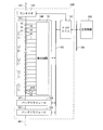
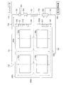
- FIG. 1 is a block diagram showing the configuration of the battery system according to the first embodiment.
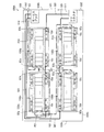
- FIG. 2 is an external perspective view of the battery module.
- FIG. 3 is a plan view of the battery module.
- FIG. 4 is a side view of the battery module.
- FIG. 5 is a plan view of the voltage bus bar.
- FIG. 6 is a plan view of the voltage / current bus bar.
- FIG. 7 is an external perspective view showing a state in which a plurality of voltage bus bars and voltage / current bus bars are attached to the FPC board.
- FIG. 8 is an external perspective view of one end of the battery module.
- FIG. 9 is an external perspective view of the other end of the battery module.
- FIG. 10 is a side view of the battery block.
- FIG. 1 is a block diagram showing the configuration of the battery system according to the first embodiment.
- FIG. 2 is an external perspective view of the battery module.
- FIG. 3 is a plan view of the battery module.
- FIG. 4 is a side
- FIG. 11 is a schematic plan view for explaining the connection between a plurality of voltage bus bars and voltage / current bus bars and a detection circuit.
- FIG. 12 is a schematic plan view for explaining the connection between a plurality of voltage bus bars and voltage / current bus bars and a detection circuit.
- FIG. 13 is a circuit diagram showing a configuration example of the detection circuit of FIG.
- FIG. 14 is a circuit diagram showing a configuration example of the amplifier circuit of FIG.
- FIG. 15 is a circuit diagram showing another configuration example of the detection circuit of FIG.
- FIG. 16 is a plan view of a voltage / current bus bar in another example.
- FIG. 17 is a diagram illustrating a configuration example of a detection circuit having a current calculation function.
- FIG. 18 is a schematic plan view showing configurations of a voltage / current bus bar and its peripheral members according to a modification.
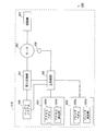
- FIG. 19 is a block diagram illustrating a configuration of an electric vehicle including the battery system of FIG.
- FIG. 20 is a block diagram showing a configuration of a power supply device according to the third embodiment.
- FIG. 21 is a schematic plan view showing the configuration of the battery system of the power supply device.
- FIG. 22 is a perspective view of a rack that houses a plurality of battery systems.
- 23 is a schematic plan view showing a state in which the battery system of FIG. 21 is housed in the housing space of the rack of FIG.
- FIG. 24 is a plan view showing another example of the battery module in the battery system.
- FIG. 25 is a plan view showing still another example of the battery module in the battery system.
- FIG. 26 is a schematic plan view showing another configuration of the power supply device.
- FIG. 27 is a schematic plan view showing a configuration of a battery system in another configuration of the power supply device.
- FIG. 28 is a side view showing another configuration of the battery block.
- FIG. 29 is an external perspective view showing a state in which a plurality of voltage bus bars and voltage / current bus bars are attached to the FPC board.
- FIG. 30 is an external perspective view showing another example of the wiring member.
- the battery module and the battery system according to the present embodiment are mounted on an electric vehicle (for example, an electric vehicle) that uses electric power as a drive source.
- an electric vehicle for example, an electric vehicle
- FIG. 1 is a block diagram showing the configuration of the battery system according to the first embodiment.
- a battery system 500 includes a plurality of battery modules 100, a battery ECU (Electronic Control Unit) 101 and a contactor 102, and is connected to a main control unit 300 of an electric vehicle via a bus 104. ing.
- a battery ECU Electronic Control Unit
- the plurality of battery modules 100 of the battery system 500 are connected to each other through the power line 501.
- Each battery module 100 includes a plurality (18 in this example) of battery cells 10, a plurality (5 in this example) of thermistors 11 and a detection circuit 20.
- each battery module 100 the plurality of battery cells 10 are integrally arranged so as to be adjacent to each other, and are connected in series by a plurality of bus bars 40.
- Each battery cell 10 is a secondary battery such as a lithium ion battery or a nickel metal hydride battery.
- the battery cells 10 arranged at both ends are connected to the power supply line 501 via the bus bar 40. Thereby, in the battery system 500, all the battery cells 10 of the plurality of battery modules 100 are connected in series.
- a power line 501 drawn from the battery system 500 is connected to a load such as a motor of an electric vehicle.
- the detection circuit 20 is connected to each bus bar 40 via a conductor wire 51 (see FIG. 11 described later).
- the detection circuit 20 is electrically connected to each thermistor 11.
- the detection circuit 20 detects the terminal voltage (battery voltage) and temperature of each battery cell 10.
- the detection circuit 20 of each battery module 100 is connected to the battery ECU 101 via the bus 103. Thereby, the voltage and temperature detected by the detection circuit 20 are given to the battery ECU 101.
- an amplifier circuit 410 is provided between the bus bar 40 of the battery cell 10 at one end and the detection circuit 20 to amplify a voltage drop due to a current flowing through each bus bar 40.
- Detection circuit 20 provides battery ECU 101 with a voltage value based on the output voltage of amplifier circuit 410. Thereby, the battery ECU 101 calculates the value of the current flowing through the battery module 100. Details of the bus bar 40 and the amplifier circuit 410 and details of calculation of the current value by the detection circuit 20 and the battery ECU 101 will be described later.
- the battery ECU 101 calculates the charge amount of each battery cell 10 based on, for example, the voltage and temperature supplied from each detection circuit 20 and the detected current, and performs charge / discharge control of each battery module 100 based on the charge amount. Do. Further, the battery ECU 101 detects the state of each battery module 100 based on the applied voltage and temperature and the detected current, for example, the life and abnormality of the battery cell 10.
- the abnormality of the battery module 100 is, for example, overdischarge, overcharge, or temperature abnormality of the battery cell 10.
- the contactor 102 is inserted in the power supply line 501 connected to the battery module 100 at one end.
- the battery ECU 101 detects an abnormality in the battery module 100, the battery ECU 101 turns off the contactor 102. Thereby, when an abnormality occurs, no current flows through each battery module 100, and thus abnormal heat generation of the battery module 100 is prevented.
- the battery ECU 101 is connected to the main control unit 300 of the electric vehicle via the bus 104.
- a charge amount of each battery module 100 (a charge amount of each battery cell 10) is given from each battery ECU 101 to main controller 300.
- the main control unit 300 controls the power of the electric vehicle (for example, the rotational speed of the motor) based on the amount of charge.
- the main control unit 300 controls a power generation device (not shown) connected to the power line 501 to charge each battery module 100.
- FIG. 2 is an external perspective view of the battery module 100
- FIG. 3 is a plan view of the battery module 100
- FIG. 4 is a side view of the battery module 100.
- three directions orthogonal to each other are defined as an X direction, a Y direction, and a Z direction, as indicated by arrows X, Y, and Z.
- the X direction and the Y direction are directions parallel to the horizontal plane
- the Z direction is a direction orthogonal to the horizontal plane.
- a plurality of battery cells 10 having a flat, substantially rectangular parallelepiped shape are arranged in the X direction.
- the plurality of battery cells 10 are integrally fixed by a pair of end face frames 92, a pair of upper end frames 93 and a pair of lower end frames 94.
- the battery block 10 ⁇ / b> B is configured by the plurality of battery cells 10, the pair of end face frames 92, the pair of upper end frames 93, and the pair of lower end frames 94.
- the pair of end face frames 92 have a substantially plate shape and are arranged in parallel to the YZ plane.
- the pair of upper end frames 93 and the pair of lower end frames 94 are arranged so as to extend in the X direction.
- connection portions for connecting the pair of upper end frames 93 and the pair of lower end frames 94 are formed.
- the pair of upper end frames 93 are attached to the upper connection portions of the pair of end surface frames 92, and the lower connection of the pair of end surface frames 92 is performed.
- a pair of lower end frames 94 are attached to the part.
- a rigid printed circuit board (hereinafter abbreviated as a printed circuit board) 21 is attached to one end face frame 92. Further, a protection member 95 having a pair of side surface portions and a bottom surface portion is attached to the end surface frame 92 so as to protect both end portions and the lower portion of the printed circuit board 21. The printed circuit board 21 is protected by being covered with a protective member 95. A detection circuit 20 and an amplification circuit 410 are provided on the printed circuit board 21.
- a cooling plate 96 is provided on the lower surface of the battery block 10B so as to be in contact with the plurality of battery cells 10.
- the cooling plate 96 has a refrigerant inlet 96a and a refrigerant outlet 96b. Inside the cooling plate 96, a circulation path connected to the refrigerant inlet 96a and the refrigerant outlet 96b is formed. When a coolant such as cooling water flows into the coolant inlet 96a, the coolant passes through the circulation path inside the cooling plate 96 and flows out from the coolant outlet 96b. Thereby, the cooling plate 96 is cooled. As a result, the plurality of battery cells 10 are cooled.
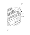
- the plurality of battery cells 10 have a plus electrode 10a on the upper surface portion on one end side and the other end side in the Y direction, and a minus electrode 10b on the upper surface portion on the opposite side. Each electrode 10a, 10b is provided so as to protrude upward.
- the positive electrode 10a of the battery cell 10 is made of aluminum. Further, the negative electrode 10b of the battery cell 10 is made of copper.
- the positive electrode 10a of the battery cell 10 is formed of aluminum, but instead of this, it may be formed of an alloy of aluminum and another metal.
- the negative electrode 10b of the battery cell 10 is formed of copper, but may be formed of an alloy of copper and another metal instead.
- the plurality of battery cells 10 have a gas vent valve 10v in the center of the upper surface portion.
- the gas inside the battery cell 10 is discharged from the gas vent valve 10v of the battery cell 10. Thereby, the rise in the pressure inside the battery cell 10 is prevented.
- the battery cell 10 adjacent to one end face frame 92 (the end face frame 92 to which the printed circuit board 21 is attached) to the battery cell 10 adjacent to the other end face frame 92 are from the first to the 18th.
- the battery cell 10 is called.
- each battery cell 10 is arranged so that the positional relationship between the plus electrode 10 a and the minus electrode 10 b in the Y direction is opposite between adjacent battery cells 10.
- the plus electrode 10a of one battery cell 10 and the minus electrode 10b of the other battery cell 10 are close to each other, and the minus electrode 10b of one battery cell 10 and the other electrode are The positive electrode 10a of the battery cell 10 is in close proximity.
- the bus bar 40 is attached to two adjacent electrodes. Thereby, the some battery cell 10 is connected in series.
- a common bus bar 40 is attached to the negative electrode 10b of the first battery cell 10 and the positive electrode 10a of the second battery cell 10.
- a common bus bar 40 is attached to the negative electrode 10b of the second battery cell 10 and the positive electrode 10a of the third battery cell 10.
- a common bus bar 40 is attached to the minus electrode 10b of each odd-numbered battery cell 10 and the plus electrode 10a of the even-numbered battery cell 10 adjacent thereto.
- a common bus bar 40 is attached to the minus electrode 10b of each even-numbered battery cell 10 and the plus electrode 10a of the odd-numbered battery cell 10 adjacent thereto.
- a bus bar 40 for connecting a power supply line 501 from the outside is attached to the plus electrode 10a of the first battery cell 10 and the minus electrode 10b of the 18th battery cell 10, respectively.
- the bus bar 40 attached to the negative electrode 10b of the 18th battery cell 10 is used as a shunt resistor RS for current detection.
- bus bars 40 are arranged in two rows along the X direction on the battery block 10B.
- Two long flexible printed circuit boards (hereinafter abbreviated as FPC boards) 50 extending in the X direction are arranged inside the two rows of bus bars 40.
- One FPC board 50 is arranged between the gas vent valves 10v of the plurality of battery cells 10 and the bus bars 40 in one row so as not to overlap the gas vent valves 10v of the plurality of battery cells 10. .
- the other FPC board 50 is disposed between the gas vent valves 10v of the plurality of battery cells 10 and the other plurality of bus bars 40 so as not to overlap the gas vent valves 10v of the plurality of battery cells 10. Arranged.
- One FPC board 50 is commonly connected to one row of the plurality of bus bars 40. Similarly, the other FPC board 50 is commonly connected to the plurality of bus bars 40 in the other row.
- Each FPC board 50 has a configuration in which a plurality of conductor lines 51 and 52 (see FIG. 11 described later) are mainly formed on an insulating layer, and has flexibility and flexibility.
- polyimide is used as the material of the insulating layer constituting the FPC board 50
- copper is used as the material of the conductor wires 51 and 52, for example.
- copper is used as the material of the conductor wires 51 and 52, but instead of this, an alloy of copper and another metal may be used.
- Each FPC board 50 is folded downward at the upper end portion of one end face frame 92 and connected to the printed circuit board 21.
- the plurality of bus bars 40 are connected to the detection circuit 20 through the plurality of conductor lines 51. Further, the bus bar 40 attached to the battery cell 10 at one end (in this example, the 18th battery cell 10) is connected to the amplifier circuit 410 through the conductor wire 51 and a conductor wire 52 described later. Details will be described later.
- the bus bar 40 for connecting the plus electrode 10a and the minus electrode 10b of two adjacent battery cells 10 is referred to as a voltage bus bar 40x, and the battery cell 10 at one end (in this example, the 18th battery cell 10).
- the bus bar 40 for connecting the power line 501 and the power line 501 is called a voltage / current bus bar 40y.
- the voltage bus bar 40x is used as a bus bar for connection between the battery cell 10 at the other end (the first battery cell 10 in this example) and the power line 501.
- FIG. 5 is a plan view of the voltage bus bar 40x
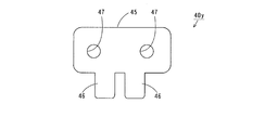
- FIG. 6 is a plan view of the voltage / current bus bar 40y.
- the voltage bus bar 40 x includes a base portion 41 and a mounting piece 42 having a substantially rectangular shape.
- the base part 41 is formed of a clad material to which two kinds of metals are bonded.
- the base part 41 is divided into two regions 41a and 41b.
- the region 41a of the base part 41 is made of aluminum, and the region 41b of the base part 41 is made of copper.
- region 41a of the base part 41 is formed with aluminum, it may replace with this and may be formed with the alloy of aluminum and another metal.
- region 41b of the base portion 41 is formed of copper, but may be formed of an alloy of copper and another metal instead.
- the mounting piece 42 is formed so as to protrude from the long side of the region 41 b of the base portion 41.
- electrode connection holes 43 are formed in the regions 41a and 41b of the base portion 41, respectively.
- the voltage / current bus bar 40y includes a base portion 45 having a substantially rectangular shape and a pair of mounting pieces 46.
- the pair of attachment pieces 46 are formed so as to protrude from the long side of the base portion 45 at a distance from each other. Further, a pair of electrode connection holes 47 is formed in the base portion 45.
- the voltage / current bus bar 40y is made of copper. A region extending from one attachment piece 46 of the voltage / current bus bar 40y through the base portion 45 to the other attachment piece 46 is used as the shunt resistor RS (see FIGS. 2 and 3). Details will be described later.
- the voltage / current bus bar 40y is made of copper, but instead, it may be made of an alloy of copper and another metal.
- FIG. 7 is an external perspective view showing a state in which a plurality of voltage bus bars 40x and voltage / current bus bars 40y are attached to the FPC board 50.
- FIG. 7 As shown in FIG. 7, a plurality of mounting pieces 42 of the bus bar voltage bus bar 40x and a pair of mounting pieces 46 of the voltage / current bus bar 40y are attached to the two FPC boards 50 at predetermined intervals along the X direction.
- the two FPC boards 50 to which the plurality of voltage bus bars 40x and the voltage / current bus bars 40y are attached as described above are provided on the battery block 10B.
- the plus electrode 10a of the adjacent battery cell 10 is fitted into the electrode connection hole 43 in the region 41a of the voltage bus bar 40x, and the minus electrode 10b is fitted into the electrode connection hole 43 in the region 41b of the voltage bus bar 40x.
- the plus electrode 10a of the battery cell 10 is laser welded to the region 41a of the voltage bus bar 40x, and the minus electrode 10b is laser welded to the region 41b of the voltage bus bar 40x.
- the plurality of battery cells 10 and the plurality of voltage bus bars 40x are fixed.
- the positive electrode 10a of the battery cell 10 is formed of aluminum, and the negative electrode 10b is formed of copper.
- the positive electrode 10a of the battery cell 10 is laser welded to the region 41a of the voltage bus bar 40x made of aluminum, and the negative electrode 10b of the battery cell 10 is laser welded to the region 41b of the voltage bus bar 40x made of copper.
- corrosion due to the contact of different metals does not occur between the positive electrode 10a of the battery cell 10 and the voltage bus bar 40x and between the negative electrode 10b of the battery cell 10 and the voltage bus bar 40x.
- the durability and reliability of the battery module 100 is improved.
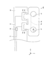
- FIG. 8 is an external perspective view of one end portion of the battery module 100.
- the power line 501 is connected to the negative electrode 10b of the battery cell 10 at one end (in this example, the 18th battery cell 10) through the voltage / current bus bar 40y.
- the power line 501 has a ring terminal 501t made of, for example, copper at the end.
- the power supply line 501 and the ring terminal 501t are formed of copper, but may be formed of an alloy of copper and another metal instead.
- the negative electrode 10b of the battery cell 10 at one end is fitted into one electrode connection hole 47 (see FIG. 6) of the voltage / current bus bar 40y.
- the negative electrode 10b of the battery cell 10 at one end is laser welded to the voltage / current bus bar 40y.
- the voltage / current bus bar 40y is fixed to the minus electrode 10b of the battery cell 10 at one end, and the voltage / current bus bar 40y is electrically connected to the minus electrode 10b of the battery cell 10.
- the screw S is formed in one end face frame 92 of the battery module 100 through the through hole of the ring terminal 501t of the power supply line 501 and the other electrode connection hole 43 (see FIG. 6) of the voltage / current bus bar 40y. Screwed onto. Accordingly, the voltage / current bus bar 40y is fixed to the one end face frame 92, and the voltage / current bus bar 40y is electrically connected to the ring terminal 501t of the power supply line 501.
- the negative electrode 10b of the battery cell 10 at one end is laser-welded to the voltage / current bus bar 40y made of copper. Further, the ring terminal 501t of the power supply line 501 is attached to the voltage / current bus bar 40y made of copper.
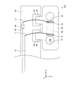
- FIG. 9 is an external perspective view of the other end portion of the battery module 100.
- the power line 501 is connected to the positive electrode 10a of the battery cell 10 at the other end (the first battery cell 10 in this example) through the voltage bus bar 40x.
- the positive electrode 10a of the battery cell 10 at the other end is fitted into the electrode connection hole 43 (see FIG. 5) in the region 41a of the voltage bus bar 40x.
- the plus electrode 10a of the battery cell 10 at the other end is laser welded to the region 41a of the voltage bus bar 40x.
- the voltage bus bar 40x is fixed to the positive electrode 10a of the battery cell 10 at the other end, and the region 41a of the voltage bus bar 40x is electrically connected to the positive electrode 10a of the battery cell 10.
- the screw S is formed in the other end face frame 92 of the battery module 100 through the through hole of the ring terminal 501t of the power line 501 and the electrode connection hole 43 (see FIG. 5) of the region 41b of the voltage bus bar 40x. Screwed onto. Accordingly, the voltage bus bar 40x is fixed to the other end face frame 92, and the region 41b of the voltage bus bar 40x is electrically connected to the ring terminal 501t of the power supply line 501.
- the plus electrode 10a of the battery cell 10 at the other end is laser welded to the region 41a of the voltage bus bar 40x made of aluminum. Further, the ring terminal 501t of the power supply line 501 is attached to the region 41b of the voltage bus bar 40x made of copper.
- the plurality of voltage bus bars 40x and the voltage / current bus bar 40y are attached to the plurality of battery cells 10, and the FPC board 50 is held in a substantially horizontal posture by the plurality of voltage bus bars 40x and the voltage / current bus bar 40y.
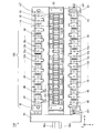
- FIG. 10 is a side view of the battery block 10B.
- the plurality of voltage bus bars 40x and the voltage / current bus bar 40y are laser-welded to the plus electrode 10a and the minus electrode 10b of the battery cell 10, the plurality of voltage bus bars 40x and the voltage / current bus bar 40y and the battery cell 10 are connected to each other.
- a coupling member to be coupled is not necessary. Thereby, the size of the battery block 10B in the height direction (Z direction) can be reduced.
- FIGS. 11 and 12 are schematic plan views for explaining the connection between the plurality of voltage bus bars 40x and voltage / current bus bars 40y and the detection circuit 20.
- one FPC board 50 is commonly connected to a plurality of voltage bus bars 40x in one row.
- the other FPC board 50 is connected in common to the plurality of voltage bus bars 40x and voltage / current bus bars 40y in the other row.
- One FPC board 50 is provided with a plurality of conductive plates 59, a plurality of conductor wires 51, and a plurality of PTC elements 60 corresponding to the mounting pieces 42 of the plurality of voltage bus bars 40x.
- the attachment pieces 42 of the plurality of voltage bus bars 40x are attached to corresponding conductive plates 59 on one FPC board 50 by soldering.
- the conductive plates 59 corresponding to the mounting pieces 42 of the plurality of voltage bus bars 40x are connected to the detection circuit 20 via the conductor lines 51 and the conductor lines on the printed circuit board 21. Thereby, the plurality of voltage bus bars 40 x are electrically connected to the detection circuit 20.
- the other FPC board 50 is provided with a plurality of conductive plates 59, a plurality of conductor lines 51, and a plurality of PTC elements 60 corresponding to the mounting pieces 42 of the plurality of voltage bus bars 40x.
- the other FPC board 50 is provided with a conductive plate 59, a conductor wire 51, and a plurality of PTC elements 60 corresponding to one mounting piece 46 of the voltage / current bus bar 40y.
- the other FPC board 50 is provided with a conductive plate 59 and a conductor wire 52 corresponding to the other mounting piece 46 of the voltage / current bus bar 40y.
- the mounting pieces 42 of the plurality of voltage bus bars 40x and the pair of mounting pieces 46 of the voltage / current bus bar 40y are attached to the corresponding conductive plates 59 on the other FPC board 50 by soldering.
- the conductive plates 59 corresponding to the mounting pieces 42 of the plurality of voltage bus bars 40x are connected to the detection circuit 20 via the conductor lines 51 and the conductor lines on the printed circuit board 21. Thereby, the plurality of voltage bus bars 40 x are electrically connected to the detection circuit 20.
- the plurality of conductor wires 51 and the conductive plate 59 are made of copper.
- the conductive plate 59 is formed of copper.
- the conductive plate 59 may be formed of an alloy of copper and another metal (copper alloy).
- the region 41b of the base portion 41 of the voltage bus bar 40x and the voltage / current bus bar 40y soldered to the conductive plate 59 are also formed of copper or a copper alloy.
- the soldering of the conductive plate 59 of the FPC board 50, the region 41b of the base portion 41 of the voltage bus bar 40x, and the voltage / current bus bar 40y is a connection between copper or copper alloys. Therefore, the connection is strengthened as compared with the case of soldering aluminum or an alloy of aluminum and another metal (aluminum alloy) to copper or a copper alloy.
- the voltage bus bar 40x is used as a bus bar for connecting the battery cell 10 and the power line 501 at the other end in the connection between the plurality of voltage bus bars 40x and the voltage / current bus bar 40y and the FPC board 50. .
- a bus bar made of aluminum or an aluminum alloy can be used as a bus bar for connecting the power line 501 and the positive electrode 10a of the battery cell 10 at the other end, but the bus bar and the FPC board 50 can be used.
- the voltage bus bar 40x made of the clad material is used as a bus bar for connecting the power line 501 and the positive electrode 10a of the battery cell 10 at the other end.
- the mounting pieces 42 of the plurality of voltage bus bars 40x and the pair of voltage current bus bars 40y made of copper or a copper alloy are soldered to the conductive plate 59 of the FPC board 50. Corrosion due to contact of dissimilar metals does not occur between the attachment pieces 42 of the plurality of voltage bus bars 40x and the attachment pieces 46 of the voltage / current bus bar 40y and the conductive plate 59 of the FPC board 50. Thereby, durability and reliability of the battery module 100 are improved.
- the PTC element 60 is inserted in the conductor wire 51.
- the PTC element 60 has resistance temperature characteristics in which the resistance value increases rapidly when the temperature exceeds a certain value. For this reason, when a short circuit occurs in the detection circuit 20 and the conductor wire 51, the temperature of the PTC element 60 rises due to the current flowing through the short circuit path, thereby increasing the resistance value of the PTC element 60. This prevents a large current from flowing through the short circuit path including the PTC element 60.
- a region from one attachment piece 46 of the voltage / current bus bar 40y to the other attachment piece 46 via the base portion 45 is used as the shunt resistor RS. Note that the resistance value of the shunt resistor RS between the one conductive plate 59 and the other conductive plate 59 is set in advance.
- the conductor wire 51 corresponding to the voltage / current bus bar 40y is connected to one input terminal of the amplifier circuit 410 and the detection circuit 20 via the conductor wire on the printed circuit board 21.
- the conductor line 52 corresponding to the voltage / current bus bar 40 y is connected to the other input terminal of the amplifier circuit 410 via the conductor line on the printed circuit board 21.
- An output terminal of the amplifier circuit 410 is connected to the detection circuit 20 via a conductor line 53 on the printed circuit board 21.
- the detection circuit 20 detects the voltage between the terminals of each battery cell 10 based on the voltages of the plurality of voltage bus bars 40x and the voltage / current bus bar 40y.
- the detection circuit 20 detects the voltage value across the shunt resistor RS based on the output voltage of the amplifier circuit 410.
- the voltage value detected by the detection circuit 20 is given to the battery ECU 101 in FIG.
- the battery ECU 101 includes, for example, a CPU (Central Processing Unit) and a memory.
- the memory of battery ECU 101 stores the resistance value of shunt resistor RS in voltage / current bus bar 40y in advance.
- the battery ECU 101 calculates the value of the current flowing through the voltage / current bus bar 40y by dividing the voltage value at both ends of the shunt resistor RS given from the detection circuit 20 by the resistance value of the shunt resistor RS stored in the memory. In this way, the value of the current flowing between the plurality of battery cells 10 is detected.
- the resistance value of the shunt resistor RS may be calculated in advance based on the length of the current path and the cross-sectional area, and the calculated value may be stored in the memory in the battery ECU 101.
- the resistance value of the shunt resistor RS may be measured in advance, and the measured value may be stored in a memory in the battery ECU 101.
- the temperature of the voltage / current bus bar 40y may be detected by the thermistor 11, and the resistance value of the shunt resistor RS stored in the memory in the battery ECU 101 may be corrected by the detected temperature.
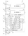
- FIG. 13 is a circuit diagram illustrating a configuration example of the detection circuit 20 of FIG.
- the detection circuit 20 shown in FIG. 13 includes first, second, and third voltage detection ICs (integrated circuits) 20a, 20b, and 20c.
- a first voltage detection IC 20a is provided corresponding to the 18th to 13th battery cells 10
- a second voltage detection IC 20b is provided corresponding to the 12th to 7th battery cells 10
- a third voltage detection IC 20 c is provided corresponding to the sixth to first battery cells 10.
- the amplifier circuit 410 is connected to the first voltage detection IC 20a.
- the reference voltages GNDa, GNDb, GNDc of the first to third voltage detection ICs 20a, 20b, 20c are electrically independent from each other.
- the first voltage detection IC 20a will be described as a representative.
- the second and third voltage detection ICs 20b and 20c have the same configuration as the first voltage detection IC 20a.
- the first voltage detection IC 20a has eight input terminals t1 to t8.
- the input terminal t7 is held at the reference voltage GNDa.
- the input terminals t7 to t1 are connected to the voltage bus bar 40x provided between the 18th to 13th battery cells 10 and the voltage / current bus bar 40y provided to the 18th battery cell 10 via the conductor line 51, respectively.
- the input terminal t8 is connected to the output terminal of the amplifier circuit 410 in FIG.
- One input terminal of the amplifier circuit 410 is connected to one end of the shunt resistor RS of the voltage / current bus bar 40y via the conductor line 51, and the other input terminal of the amplifier circuit 410 is connected to the shunt of the voltage / current bus bar 40y via the conductor line 52. Connected to the other end of the resistor RS.
- the first voltage detection IC 20a includes voltage detection units 201 to 206, switching elements 211 to 217, and an A / D (analog / digital) converter 220.
- the voltage detector 201 differentially amplifies the voltage between the input terminals t1 and t2, the voltage detector 202 differentially amplifies the voltage between the input terminals t2 and t3, and the voltage detector 203 is between the input terminals t3 and t4.
- the voltage detection unit 204 differentially amplifies the voltage between the input terminals t4 and t5, the voltage detection unit 205 differentially amplifies the voltage between the input terminals t5 and t6, and the voltage detection unit 206
- the voltage between the input terminals t6 and t7 is differentially amplified. Further, the amplifier circuit 410 amplifies the voltage across the shunt resistor RS.
- the output terminals and the input terminals t8 of the voltage detectors 201 to 206 are connected to the input terminals of the A / D converter 220 via the switching elements 211 to 217, respectively.
- the reference terminal GND of the input terminal t7 is applied to the reference terminal of the A / D converter 220, and the power supply voltage V + is applied to the power supply terminal of the A / D converter 220.
- the reference voltage GNDa at the input terminal t7 is commonly supplied to the voltage detection unit 206 and the A / D converter 220, but instead, the voltage detection unit 206 is connected to the reference terminal of the A / D converter 220. And the reference voltage GNDa may be applied separately.
- Switching elements 211 to 217 are sequentially turned on. As a result, the voltages amplified by voltage detectors 201 to 206 and amplifier circuit 410 are sequentially applied to A / D converter 220.
- the A / D converter 220 converts a given voltage into a digital voltage value.
- the digital voltage value obtained by the A / D converter 220 is given to the battery ECU 101 in FIG.
- the battery ECU 101 calculates the charge amount of each battery cell 10 based on the voltage value between the terminals of each battery cell 10 as described above. Further, the value of the current flowing through the voltage / current bus bar 40y is calculated based on the voltage value at both ends of the shunt resistor RS and the resistance value of the shunt resistor RS.
- FIG. 14 is a circuit diagram showing a configuration example of the amplifier circuit 410 in FIG.
- the resistance value of the shunt resistor RS is referred to as a shunt resistance value Rs
- the value of the voltage across the shunt resistor RS is referred to as a voltage value Vs
- the value of the current flowing through the shunt resistor RS is referred to as a current value Is.
- the current value Is can be calculated by detecting the voltage value Vs.
- the shunt resistance value Rs is small (for example, about 1 m ⁇ ).
- the current value Is varies, for example, in the range of ⁇ 100 A to 100 A
- the voltage value Vs varies in the range of ⁇ 0.1 V to 0.1 V. Note that the current value Is and the voltage value Vs are negative because the direction of the current flowing through the voltage / current bus bar 40y is opposite to that during discharging during charging.
- the first voltage detection IC 20a detects the voltage between the terminals of each battery cell 10 which fluctuates in the range of, for example, 2.5V to about 4.2V.
- the voltage value Vs across the shunt resistor RS is lower than the voltage between the terminals of each battery cell 10. Therefore, in the present embodiment, the voltage value Vs across the shunt resistor RS is amplified by the amplifier circuit 410.
- the input terminals V1, V2 and the output terminal V3 of the amplifier circuit 410 are connected to conductor lines 51, 52, 53, respectively.
- the amplifier circuit 410 includes an operational amplifier (operational amplifier) 411, a DC power supply Ea, and resistors R1 to R4.
- the non-inverting input terminal of the operational amplifier 411 is connected to the input terminal V1 through the resistor R1 and is connected to the positive electrode of the DC power supply Ea through the resistor R3.
- the inverting input terminal of the operational amplifier 411 is connected to the input terminal V2 via the resistor R2.
- a resistor R4 is connected between the inverting input terminal of the operational amplifier 411 and the output terminal V3.
- a reference voltage GNDa is applied to the reference terminal of the operational amplifier 411, and a power supply voltage Va is applied to the power supply terminal.
- the positive voltage (hereinafter referred to as offset voltage) Voff of the DC power supply Ea is set between the reference voltage GNDa and the power supply voltage Va.
- the values of the resistors R1 and R2 are set to 10 k ⁇ , and the values of the resistors R3 and R4 are set to 250 k ⁇ .
- the amplification gain of the amplifier circuit 410 is 25.
- the power supply voltage Va is set to 5V, and the offset voltage Voff is set to 2.5V.
- the amplifier circuit 410 changes the voltage value Vs that fluctuates within the range of ⁇ 0.1V to 0.1V from 0V to 5V around 2.5V. Amplifies to a voltage within the range.
- the current value Is is calculated as -100A.
- the output voltage of the amplifier circuit 410 is 2.5V.
- the current value Is is calculated as 0A.
- the current value Is is calculated as 100A.
- the voltage bus bar 40x is used as the shunt resistor RS.
- the voltage bus bar 40x connecting the plus electrode 10a and the minus electrode 10b of two adjacent battery cells 10 is formed of the same aluminum as the plus electrode 10a and the clad material made of the same copper as the minus electrode 10b. Is done.
- the voltage bus bar 40x formed of the clad material is more expensive than the bus bar formed of one kind of metal. Therefore, in the present embodiment, the low-cost voltage / current bus bar 40y formed of one kind of metal is used as the shunt resistor RS for current detection.
- the shunt resistance value Rs is set by adjusting the bus bar material and dimensions.
- the dimensions are the length and cross-sectional area of the current path. That is, the shunt resistance value Rs is limited by the size of the bus bar.
- the dimension of the voltage bus bar 40x is limited by the distance between the plus electrode 10a and the minus electrode 10b of two adjacent battery cells 10. When the thickness of each battery cell 10 is small, the length of the voltage bus bar 40x is also small. Accordingly, when the voltage bus bar 40x is used as the shunt resistor RS, it is difficult to optimally set the shunt resistance value Rs. Therefore, in the present embodiment, the voltage / current bus bar 40y is attached to the battery cell 10 at one end so that the dimension of the shunt resistor RS is not limited by the thickness of the battery cell 10.
- the bus bar connected to the plus electrode 10a of the battery cell 10 at the other end is formed of aluminum and this bus bar is used as the shunt resistor RS.
- the ring terminal 501t of the power supply line 501 is connected to a bus bar made of aluminum.
- the voltage / current bus bar 40y made of copper is attached not to the plus electrode 10a of the battery cell 10 at the other end but to the minus electrode 10b of the battery cell 10 at one end.
- FIG. 15 is a circuit diagram showing another configuration example of the detection circuit 20 of FIG.
- first, second, and third voltage detection ICs 20a, 20b, and 20c having the same configuration.
- first voltage detection IC 20a of this example details of the first voltage detection IC 20a of this example will be described.
- the first voltage detection IC 20a has eight input terminals t11 to t18.
- the input terminal t18 is held at the reference voltage GNDa.
- the input terminals t18, t16 to t11 are connected to the voltage bus bar 40x provided between the 18th to 13th battery cells 10 and the voltage / current bus bar 40y provided to the 18th battery cell 10 via the conductor line 51, respectively.
- the input terminal t17 is connected to the output terminal of the amplifier circuit 410 in FIG.
- the configuration of the amplifier circuit 410 in FIG. 15 is the same as that of the amplifier circuit 410 in FIG. Therefore, the voltage value Vs across the shunt resistor RS amplified by the amplifier circuit 410 is input to the input terminal t17.
- the first voltage detection IC 20a includes resistors 221 to 227, 231 to 237, switching elements 211 to 217, and an A / D converter 220.
- Resistors 221 and 231 are connected in series between the input terminal t11 and the input terminal t18, and resistors 222 and 232 are connected in series between the input terminal t12 and the input terminal t18, and the input terminal t13 and the input terminal Resistors 223 and 233 are connected in series with t18.
- Resistors 224 and 234 are connected in series between the input terminal t14 and the input terminal t18, and resistors 225 and 235 are connected in series between the input terminal t15 and the input terminal t18.
- Resistors 226 and 236 are connected in series between the input terminal t18, and resistors 227 and 237 are connected in series between the input terminal t17 and the input terminal t18. As a result, the voltages at the input terminals t11 to t17 are divided.
- a node N15 between the resistor 235, a node N16 between the resistor 226 and the resistor 236, and a node N17 between the resistor 227 and the resistor 237 are respectively connected to the A / D converter 220 via the switching elements 211 to 217.
- the reference voltage GNDa of the input terminal t18 is applied to the reference terminal of the A / D converter 220, and the power supply voltage V + is applied to the power supply terminal of the A / D converter 220.
- Switching elements 211 to 217 are sequentially turned on. Thereby, the voltages of the nodes N11 to N17 are sequentially supplied to the A / D converter 220.
- the resistors 221 to 227 and the resistors 231 to 237 are set so that the voltages at the nodes N11 to N17 are lower than the power supply voltage V + from the reference voltage GNDa of the A / D converter 220.
- the A / D converter 220 converts the given voltage into a digital voltage value.
- the digital voltage value obtained by the A / D converter 220 is given to the battery ECU 101 in FIG.
- the charge amount of each battery cell 10 is calculated by the battery ECU 101 based on the voltage value of each battery cell 10. Further, the current value Is flowing through the voltage / current bus bar 40y is calculated based on the voltage value Vs at both ends of the shunt resistor RS and the shunt resistance value Rs.
- a part of the voltage / current bus bar 40y attached to the negative electrode 10b of the battery cell 10 at one end is used as the shunt resistor RS for current detection. Therefore, the shape and dimensions of the shunt resistor RS are not limited by the interval between adjacent battery cells 10. Thereby, the shunt resistor RS can be easily set to an optimum value. Further, it is not necessary to separately provide a shunt resistor in the battery module 100. As a result, the current flowing through the battery module 100 can be detected with a simple configuration without increasing the size of the battery module 100.
- one attachment piece 46 of the voltage / current bus bar 40y corresponding to one end of the shunt resistor RS is electrically connected to the detection circuit 20 via the conductor line 51 of the FPC board 50, and
- the other attachment piece 46 of the voltage / current bus bar 40 y corresponding to the other end of the shunt resistor RS is electrically connected to the detection circuit 20 via the conductor line 52 of the FPC board 50.
- the detection circuit 20 can detect the voltage between both ends of the shunt resistor RS.
- the FPC board 50 is provided so as to extend along the plurality of voltage bus bars 40x and the voltage / current bus bar 40y.
- the plurality of voltage bus bars 40x and voltage / current bus bars 40y and the FPC board 50 can be easily connected. Thereby, the voltage between the terminals of each battery cell 10 can be detected by the detection circuit 20 without complicating the wiring.
- the current flowing through the shunt resistor RS is calculated by the battery ECU 101 of the battery system 500. As a result, the current flowing through the battery module 100 can be detected with a simpler configuration.
- the voltage / current bus bar 40y is laser welded to the negative electrode 10b of the battery cell 10 at one end and is fixed to one end face frame 92 with a screw S.
- the screw S is used as an output terminal for outputting the electric power of the battery module 100 to the outside. Therefore, it is not necessary to provide an additional terminal on the battery block 10B in order to connect the shunt resistor RS. Thereby, the shunt resistor RS can be provided in the battery module 100 without increasing the manufacturing process and the manufacturing cost.
- the negative electrode 10b of each battery cell 10, the region 41b of the voltage bus bar 40x, and the voltage / current bus bar 40y are formed of copper, and the positive electrode 10a of each battery cell 10 and the region 41a of the voltage bus bar 40x are formed of aluminum.
- the region 41b of the voltage bus bar 40x and the negative electrode 10b of one battery cell 10 between the region 41a of the voltage bus bar 40x and the positive electrode 10a of the other battery cell 10, and the battery cell at one end of the voltage / current bus bar 40y Corrosion due to contact of dissimilar metals does not occur between one of the electrodes. As a result, the durability and reliability of the battery module 100 is improved.
- the ring terminal 501t and the power supply line 501 can be formed of copper. Accordingly, it is not necessary to adopt a special configuration for preventing corrosion due to contact of different metals on the ring terminal 501t and the power supply line 501. As a result, an increase in cost due to the provision of the shunt resistor RS in the voltage / current bus bar 40y can be suppressed.
- the FPC board 50, the plurality of voltage bus bars 40x and the voltage / current bus bar 40y arranged on the upper surface of the battery block 10B constitute a wiring member 70 of FIG. 29 described later.
- the positive electrode 10 a or the negative electrode 10 b of each battery cell 10 and the detection circuit 20 are connected by the wiring member 70.
- the positive electrode 10 a or the negative electrode 10 b of the plurality of battery cells 10 and the detection circuit 20 are connected by the plurality of conductor lines 51. Further, the negative electrode 10 b of the battery cell 10 at one end and the amplifier circuit 410 are connected by a conductor line 52.
- the wiring member 70 is a member that integrates the plurality of conductor wires 52 and the conductor wires 51.
- the voltage / current bus bar 40y constituting the wiring member 70 is laser-welded to the negative electrode 10b of the battery cell 10 at one end, similarly to the voltage bus bar 40x. Accordingly, the shunt resistor RS is attached on the upper surface of the battery block 10B without protruding from the battery block 10B and maintaining the flatness of the battery block 10B.
- the voltage / current bus bar 40y including the shunt resistor RS is connected to the negative electrode 10b of the battery cell 10 at one end, similarly to the other voltage bus bars 40x. Welded. Thereby, compared with the case where the voltage bus bar 40x and the voltage current bus bar 40y are attached to the plus electrode 10a or the minus electrode 10b of the battery cell 10 with screws, the size of the height of the battery module 100 can be reduced.
- the positive electrode 10a of the battery cell 10 is formed of aluminum, but the present invention is not limited to this.
- the positive electrode 10a of the battery cell 10 may be formed of, for example, an aluminum alloy having high strength and low resistivity.
- the region 41a of the voltage bus bar 40x is preferably formed of the same aluminum alloy as the plus electrode 10a of the battery cell 10.
- the negative electrode 10b of the battery cell 10 may be formed of, for example, silver, gold, or an alloy thereof having high strength and low resistivity.
- the region 41b of the voltage bus bar 40x and the conductive plate 59 of the FPC board 50 are preferably formed of the same silver, gold, or alloy thereof as the negative electrode 10b of the battery cell 10.
- the voltage / current bus bar 40y may be formed of a copper alloy such as copper manganese or copper nickel, for example. Thereby, a part of the voltage / current bus bar 40y can be easily used as the shunt resistor RS.
- a part of the bus bar attached to the negative electrode 10b of the battery cell 10 at one end is used as the shunt resistor RS, but is not limited thereto.
- a part of the bus bar attached to the plus electrode 10a of the battery cell 10 at the other end may be used as the shunt resistor RS.
- FIG. 16 is a plan view of a voltage / current bus bar 40z in another example.
- the voltage / current bus bar 40z includes a base portion 44 and a mounting piece 48 having a substantially rectangular shape.
- the base portion 44 is formed of a clad material to which two kinds of metals are bonded.
- the base portion 44 is divided into two regions 44a and 44b.
- the region 44a of the base portion 44 is made of aluminum, and the region 44b of the base portion 44 is made of copper.
- the pair of attachment pieces 48 are formed so as to protrude from the long side of the region 44b of the base portion 44 at a distance from each other.
- electrode connection holes 49 are formed in the regions 44a and 44b of the base portion 44, respectively.
- a region from one attachment piece 48 of the voltage / current bus bar 40z to the other attachment piece 48 via the base portion 44 is used as the shunt resistor RS.
- the electrode connection hole 49 formed in the region 44a of the voltage / current bus bar 40z is attached to the positive electrode 10a of the battery cell 10 at the other end (see FIG. 9). Further, the screw S is screwed into a screw hole formed in the other end face frame 92 of the battery module 100 through the through hole of the ring terminal 501t of the power supply line 501 and the electrode connection hole 49 of the region 44b of the voltage / current bus bar 40z. (See FIG. 9). Thereby, the electric current which flows into the battery module 100 is detected based on the voltage of the both ends of shunt resistance RS.
- the voltage / current bus bar 40y attached to the negative electrode 10b of the battery cell 10 at one end and the ring terminal 501t of the power supply line 501 are fixed to one end face frame 92 with screws S.
- One end face frame 92 may be provided with an output terminal, and the voltage / current bus bar 40y attached to the negative electrode 10b of the battery cell 10 at one end and the end of the power supply line 501 may be laser-welded to the output terminal, for example.
- the voltage bus bar 40x attached to the plus electrode 10a of the battery cell 10 at the other end and the ring terminal 501t of the power supply line 501 are fixed to the other end face frame 92 with screws S, but the present invention is not limited to this.
- An output terminal may be provided on the other end face frame 92, and the voltage bus bar 40x attached to the positive electrode 10a of the battery cell 10 at the other end and the end of the power supply line 501 may be laser-welded to the output terminal, for example.
- the positive electrode 10a of the battery cell 10 and the region 41a of the voltage bus bar 40x are fixed by laser welding, but the present invention is not limited to this.
- the positive electrode 10a of the battery cell 10 and the region 41a of the voltage bus bar 40x may be fixed by other welding, caulking, or screws.
- region 41b of the voltage bus bar 40x are fixed by laser welding, it is not limited to this.
- the negative electrode 10b of the battery cell 10 and the region 41b of the voltage bus bar 40x may be fixed by other welding, caulking, or screws.
- the negative electrode 10b of the battery cell 10 at one end and the voltage / current bus bar 40y are fixed by laser welding, the present invention is not limited to this.
- the negative electrode 10b of the one-end battery cell 10 and the voltage / current bus bar 40y may be fixed by other welding, caulking, or screws.
- the attachment pieces 42 of the plurality of voltage bus bars 40x and the pair of attachment pieces 46 of the voltage / current bus bar 40y are attached to the corresponding conductive plates 59 on the FPC board 50 by soldering.
- the attachment pieces 42 of the plurality of voltage bus bars 40x and the pair of attachment pieces 46 of the voltage / current bus bar 40y may be attached to the corresponding conductive plates 59 on the FPC board 50 by welding.
- the battery ECU 101 calculates the current value Is of the voltage / current bus bar 40y based on the voltage value Vs and the shunt resistance value Rs at both ends of the shunt resistor RS of the voltage / current bus bar 40y. Although it had a function, it is not limited to this. Instead of the battery ECU 101, the detection circuit 20 may have a current calculation function.
- FIG. 17 is a diagram illustrating a configuration example of the detection circuit 20 having a current calculation function.
- the detection circuit 20 is provided with, for example, a microcomputer 20m in addition to the configuration of FIG. Then, the shunt resistance value Rs in the voltage / current bus bar 40y is stored in the microcomputer 20m of the detection circuit 20 in advance.
- the microcomputer 20m of the detection circuit 20 calculates the current value Is of the voltage / current bus bar 40y based on the voltage value Vs at both ends of the shunt resistor and the shunt resistance value Rs output from the first voltage detection IC 20a in FIG. It may be calculated.
- the microcomputer 20m of the detection circuit 20 may calculate the inter-terminal voltage of each battery cell 10 based on the outputs of the first to third voltage detection ICs 20a to 20c.
- the calculated current value Is and the inter-terminal voltage of each battery cell 10 are given to the battery ECU 101.
- the microcomputer 20m of the detection circuit 20 determines the calculated current value Is, the calculated inter-terminal voltage of each battery cell 10, and the temperature of each battery cell 10 detected by the thermistor 11 of FIG. Based on this, the charge amount of each battery cell 10 may be calculated.
- the calculated current value Is the calculated inter-terminal voltage of each battery cell 10, the detected temperature of each battery cell 10, and the charge amount of each battery cell 10 are given from the microcomputer 20m to the battery ECU 101. It is done.
- the current calculation function may be realized by providing a CPU and a memory instead of the microcomputer 20m.
- the microcomputer 20m of this example, or the CPU and the memory can be provided, for example, on the printed circuit board 21 of FIG.
- FIG. 18 is a schematic plan view showing the configuration of the voltage / current bus bar 40y and its peripheral members according to a modification. The difference between the voltage / current bus bar 40y according to the modification and the voltage / current bus bar 40y of FIG. 12 will be described.
- solder patterns H1 and H2 are formed in parallel with each other at regular intervals.
- the solder pattern H1 is disposed in the vicinity of one electrode connection hole 47 between the pair of electrode connection holes 47, and the solder pattern H2 is disposed in the vicinity of the other electrode connection hole 47 between the electrode connection holes 47.
- the solder pattern H1 of the voltage / current bus bar 40y is connected to the corresponding conductor wire 51 on the detection circuit 20 (see FIG. 11) by the wire L1.
- a PTC element 60 is inserted in the conductor wire 51.
- the solder pattern H2 of the voltage / current bus bar 40y is connected to the corresponding conductor line 52 on the detection circuit 20 by the wire L2. Note that the PTC element 60 may be inserted in either of the conductor wires 51 and 52. In the example of FIG. 18, the PTC element 60 is inserted in the conductor line 52.
- the resistance formed between the solder patterns H1 and H2 of the voltage / current bus bar 40y is the shunt resistance RS for current detection.
- the shunt resistance value Rs is calculated based on the length of the current path, the cross-sectional area, and the resistivity. Therefore, it is preferable to form the solder patterns H1 and H2 so that the value of the shunt resistor RS in the voltage / current bus bar 40y can be accurately calculated.
- the solder patterns H1 and H2 are preferably formed so as to be close to the electrode connection hole 47 and extend in a direction orthogonal to a straight line connecting the centers of the electrode connection holes 47. Furthermore, it is preferable that the lengths of the solder patterns H1 and H2 are both substantially equal to the diameter of the electrode connection hole 47.
- the value of the shunt resistance RS is calculated in advance, and the calculated value is stored in the battery. You may memorize
- the value of the shunt resistance RS between the solder patterns H1 and H2 may be measured in advance, and the measured value may be stored in the memory in the battery ECU 101.
- the resistance between the solder patterns H1 and H2 formed on the voltage / current bus bar 40y is used as the shunt resistance RS. Therefore, the shunt resistance value Rs can be easily set to an optimum value by adjusting the dimensions of the solder patterns H1 and H2.
- the electric vehicle according to the present embodiment includes battery module 100 and battery system 500 according to the first embodiment.
- an electric vehicle will be described as an example of an electric vehicle.
- FIG. 19 is a block diagram showing a configuration of an electric vehicle including the battery system 500 of FIG.
- electric vehicle 600 according to the present embodiment includes a vehicle body 610.
- the vehicle body 610 is provided with the main control unit 300 and the battery system 500, the power conversion unit 601, the motor 602, the drive wheel 603, the accelerator device 604, the brake device 605, and the rotation speed sensor 606 of FIG.
- motor 602 is an alternating current (AC) motor
- power conversion unit 601 includes an inverter circuit.
- the battery system 500 is connected to the motor 602 via the power converter 601 and to the main controller 300.
- the main controller 300 is given the charge amount of the plurality of battery modules 100 (see FIG. 1) and the value of the current flowing through the battery modules 100 from the battery ECU 101 (see FIG. 1) constituting the battery system 500.
- an accelerator device 604, a brake device 605, and a rotation speed sensor 606 are connected to the main control unit 300.
- the main control unit 300 includes, for example, a CPU and a memory, or a microcomputer.
- the accelerator device 604 includes an accelerator pedal 604a included in the electric automobile 600 and an accelerator detection unit 604b that detects an operation amount (depression amount) of the accelerator pedal 604a.
- the accelerator detector 604b detects the operation amount of the accelerator pedal 604a based on a state where the driver is not operated. The detected operation amount of the accelerator pedal 604a is given to the main controller 300.
- the brake device 605 includes a brake pedal 605a included in the electric automobile 600 and a brake detection unit 605b that detects an operation amount (depression amount) of the brake pedal 605a by the driver.
- the operation amount is detected by the brake detection unit 605b.
- the detected operation amount of the brake pedal 605a is given to the main control unit 300.
- Rotational speed sensor 606 detects the rotational speed of motor 602. The detected rotation speed is given to the main control unit 300.
- the main controller 300 is given the charge amount of the battery module 100, the current value flowing through the battery module 100, the operation amount of the accelerator pedal 604a, the operation amount of the brake pedal 605a, and the rotation speed of the motor 602. .
- the main control unit 300 performs charge / discharge control of the battery module 100 and power conversion control of the power conversion unit 601 based on these pieces of information.
- the battery module 100 supplies power to the power conversion unit 601.
- the main control unit 300 calculates a rotational force (command torque) to be transmitted to the drive wheels 603 based on the given operation amount of the accelerator pedal 604a, and outputs a control signal based on the command torque to the power conversion unit 601. To give.
- the power conversion unit 601 that has received the control signal converts the power supplied from the battery system 500 into power (drive power) necessary for driving the drive wheels 603. As a result, the driving power converted by the power converter 601 is supplied to the motor 602, and the rotational force of the motor 602 based on the driving power is transmitted to the driving wheels 603.
- the motor 602 functions as a power generator.
- the power conversion unit 601 converts the regenerative power generated by the motor 602 into power suitable for charging the battery module 100 and supplies the power to the battery module 100. Thereby, the battery module 100 is charged.
- the electric vehicle 600 according to the present embodiment is provided with the battery system 500 according to the first embodiment.
- the current flowing through the battery module 100 is detected with a simple configuration.
- the electric vehicle 600 can be controlled based on the value of the current flowing through the battery module 100.
- the battery module 100 (battery system 500) is mounted on an electric vehicle has been described, but the battery module 100 may be mounted on another moving body such as a ship, an aircraft, or a walking robot.
- a ship on which the battery module 100 is mounted includes, for example, a hull instead of the vehicle body 610 in FIG. 19, a screw instead of the drive wheel 603, an acceleration input unit instead of the accelerator device 604, and a brake device 605.
- a deceleration input unit is provided.
- the driver operates the acceleration input unit instead of the accelerator device 604 when accelerating the hull, and operates the deceleration input unit instead of the brake device 605 when decelerating the hull.
- the motor 602 is driven by the electric power of the battery module 100, and the propulsive force is generated by transmitting the rotational force of the motor 602 to the screw, so that the hull moves.
- an aircraft equipped with the battery module 100 includes, for example, a fuselage instead of the vehicle body 610 in FIG. 19, a propeller instead of the driving wheel 603, an acceleration input unit instead of the accelerator device 604, and a brake.
- a deceleration input unit is provided instead of the device 605.
- a walking robot equipped with the battery module 100 includes, for example, a torso instead of the vehicle body 610 in FIG. 19, a foot instead of the driving wheel 603, an acceleration input unit instead of the accelerator device 604, and a brake device 605.
- a deceleration input unit is provided instead of.
- the electric power from the battery module 100 is converted into motive power by the power source (motor), and the moving main body (the vehicle body, the hull, the fuselage, or the fuselage) is converted by the motive power.
- the power source motor
- the moving main body the vehicle body, the hull, the fuselage, or the fuselage
- FIG. 20 is a block diagram illustrating a configuration of a power supply device according to the third embodiment.
- the power supply device 700 includes a power storage device 710 and a power conversion device 720.
- the power storage device 710 includes a battery system group 711 and a controller 712.
- the battery system group 711 includes a plurality of battery systems 500A.
- Each battery system 500A includes a plurality of battery modules 100 of FIG. 2 connected in series.
- the plurality of battery systems 500A may be connected to each other in parallel, or may be connected to each other in series. Details of the battery system 500A will be described later.
- the controller 712 includes, for example, a CPU and a memory, or a microcomputer.
- the controller 712 is connected to the detection circuit 20 of each battery module 100 (FIG. 2) included in each battery system 500A.
- the terminal voltage value and temperature value detected by the detection circuit 20 of each battery module 100 are supplied to the controller 712.
- the value of the voltage across the shunt resistor RS (hereinafter simply referred to as the voltage across the shunt resistor RS) amplified by the amplifier circuit 410 (FIG. 11) is given to the controller 712 by the detection circuit 20.
- the controller 712 calculates the value of the current flowing through the battery module 100 based on the voltage value across the shunt resistor RS. Further, the controller 712 calculates and calculates the charge amount of each battery cell 10 (FIG. 2) based on the value of each terminal voltage, the temperature value, and the calculated current value given from the detection circuit 20. The power converter 720 is controlled based on the charged amount. Furthermore, the controller 712 performs control described later as control related to discharging or charging of the battery module 100 of the battery system 500.
- the power converter 720 includes a DC / DC (DC / DC) converter 721 and a DC / AC (DC / AC) inverter 722.
- the DC / DC converter 721 has input / output terminals 721a and 721b, and the DC / AC inverter 722 has input / output terminals 722a and 722b.
- the input / output terminal 721 a of the DC / DC converter 721 is connected to the battery system group 711 of the power storage device 710.
- the input / output terminal 721b of the DC / DC converter 721 and the input / output terminal 722a of the DC / AC inverter 722 are connected to each other and to the power output unit PU1.
- the input / output terminal 722b of the DC / AC inverter 722 is connected to the power output unit PU2 and to another power system.
- the power output units PU1, PU2 include, for example, outlets. For example, various loads are connected to the power output units PU1 and PU2.
- Other power systems include, for example, commercial power sources or solar cells. This is an external example in which power output units PU1, PU2 and another power system are connected to a power supply device.
- the solar cell is connected to the input / output terminal 721b of the DC / DC converter 721.
- the AC output unit of the power conditioner of the solar power generation system is connected to the input / output terminal 722 b of the DC / AC inverter 722.
- the battery system group 711 is discharged and charged.
- DC / DC direct current / direct current
- DC / AC direct current / alternating current
- the power supply device 700 When the power supply device 700 is used as a DC power supply, the power DC / DC converted by the DC / DC converter 721 is supplied to the power output unit PU1. When the power supply device 700 is used as an AC power supply, the power that is DC / AC converted by the DC / AC inverter 722 is supplied to the power output unit PU2. Moreover, the electric power converted into alternating current by the DC / AC inverter 722 can also be supplied to another electric power system.
- the controller 712 determines whether to stop discharging the battery system group 711 based on the calculated charge amount or whether to limit the discharge current (or discharge power),
- the power conversion device 720 is controlled based on the determination result. Specifically, when the charge amount of any one of the plurality of battery cells 10 (FIG. 2) included in the battery system group 711 is smaller than a predetermined threshold, the controller 712 The DC / DC converter 721 and the DC / AC inverter 722 are controlled so that the discharge of the system group 711 is stopped or the discharge current (or discharge power) is limited. Thereby, overdischarge of each battery cell 10 is prevented.
- the controller 712 determines whether to stop discharging the battery system group 711 based on an external instruction or whether to limit the discharge current (or discharge power), and determines the power conversion device 720 based on the determination result. You may control.
- the discharge current (or discharge power) is limited by limiting the voltage of the battery system group 711 to a constant reference voltage.
- the reference voltage is set by the controller 712 based on the charge amount of the battery cell 10 or an external instruction.
- the controller 712 determines whether to stop charging the battery system group 711 or limit the charging current (or charging power) based on the calculated charge amount,
- the power conversion device 720 is controlled based on the determination result. Specifically, when the charge amount of any one of the plurality of battery cells 10 (FIG. 2) included in the battery system group 711 is greater than a predetermined threshold value, the controller 712 The DC / DC converter 721 and the DC / AC inverter 722 are controlled so that the charging of the system group 711 is stopped or the charging current (or charging power) is limited. Thereby, overcharge of each battery cell 10 is prevented.
- the controller 712 determines whether to stop the charging of the battery system group 711 based on an external instruction or whether to limit the charging current (or charging power), and determines the power conversion device 720 based on the determination result. You may control.
- the charging current (or charging power) is limited by limiting the voltage of the battery system group 711 to a constant reference voltage.
- the reference voltage is set by the controller 712 based on the charge amount of the battery cell 10 or an external instruction.
- the power conversion device 720 may include only one of the DC / DC converter 721 and the DC / AC inverter 722 as long as power can be supplied between the power supply device 700 and the outside. Further, the power conversion device 720 may not be provided as long as power can be supplied between the power supply device 700 and the outside.
- FIG. 21 is a schematic plan view showing the configuration of the battery system 500A of the power supply apparatus 700.
- the battery system 500A includes four battery modules 100, a service plug 510, and an HV connector 511.
- the four battery modules 100 of the battery system 500A are referred to as battery modules 100a, 100b, 100c, and 100d, respectively.
- the end face frame 92 to which the printed circuit board 21 (FIG. 2) is attached is called an end face frame 92a, and the end face frame to which the printed circuit board 21 is not attached.
- 92 is referred to as an end face frame 92b.
- the end face frame 92a is hatched.
- the battery modules 100a to 100d, the service plug 510, and the HV connector 511 are accommodated in a box-shaped housing 550.
- the housing 550 has side surface portions 550a, 550b, 550c, and 550d.
- the side surface portions 550a and 550c are parallel to each other, and the side surface portions 550b and 550d are parallel to each other and perpendicular to the side surface portions 550a and 550c.
- the battery modules 100a and 100b are arranged so as to be arranged at a predetermined interval along the stacking direction of the battery cells 10.
- the battery modules 100c and 100d are arranged so as to be arranged at a predetermined interval along the stacking direction of the battery cells 10.
- the battery modules 100a and 100b are arranged along and close to the side surface portion 550a, and the battery modules 100c and 100d are arranged in parallel with the battery modules 100a and 100b.
- the end surface frames 92a of the battery modules 100a and 100b are respectively directed to the side surface portion 550d. Further, the end surface frames 92a of the battery modules 100c and 100d are directed to the side surface portions 550b, respectively.
- the service plug 510 is provided on the side surface portion 550b of the housing 550 so as to be adjacent to the battery module 100b.
- the HV connector 511 is provided on the side surface portion 550b of the housing 550 so as to be adjacent to the battery module 100c.
- the potential of the positive electrode 10a (FIG. 3) of the battery cell 10 (first battery cell 10) adjacent to the end face frame 92a is the highest, and the battery cell 10 adjacent to the end face frame 92b.
- the potential of the negative electrode 10b (FIG. 3) of the (18th battery cell 10) is the lowest.
- the positive electrode 10a (FIG. 3) having the highest potential is referred to as a high potential electrode 10c
- the negative electrode 10b (FIG. 3) having the lowest potential is referred to as a low potential electrode 10d.
- the low potential electrode 10d of the battery module 100a and the high potential electrode 10c of the battery module 100b are connected to each other via the power line 501.
- the low potential electrode 10d of the battery module 100c and the high potential electrode 10c of the battery module 100d are connected to each other via the power supply line 501.
- the high potential electrode 10c of the battery module 100a is connected to the service plug 510 via the power supply line 501, and the low potential electrode 10d of the battery module 100d is connected to the service plug 510 via the power supply line 501.
- the service plug 510 When the service plug 510 is turned on, the battery modules 100a to 100d are connected in series. In this case, the potential of the high potential electrode 10c of the battery module 100c is the highest, and the potential of the low potential electrode 10d of the battery module 100b is the lowest.
- the service plug 510 is turned on by being connected to an on / off switching unit 764 (FIG. 23, which will be described later). In a state where the on / off switching unit 764 is not connected, the service plug 510 is turned off.
- the service plug 510 is turned off by an operator at the time of maintenance of the battery system 500A, for example.
- the series circuit composed of the battery modules 100a and 100b and the series circuit composed of the battery modules 100c and 100d are electrically separated. In this case, the current path between the plurality of battery modules 100a to 100d is interrupted. This ensures safety during maintenance.
- the low potential electrode 10d of the battery module 100b is connected to the HV connector 511 via the power line 501 and the high potential electrode 10c of the battery module 100c is connected to the HV connector 511 via the power line 501.
- the HV connector 511 is connected to the input / output terminal 721a (FIG. 20) of the DC / DC converter 721.
- the printed circuit board 21 (FIG. 2) of the battery module 100a and the printed circuit board 21 of the battery module 100b are connected to each other via a communication line P21.
- the printed circuit board 21 of the battery module 100a and the printed circuit board 21 of the battery module 100d are connected to each other via a communication line P22.
- the printed circuit board 21 of the battery module 100c and the printed circuit board 21 of the battery module 100d are connected to each other via a communication line P23.
- a communication connection portion CC for connection with the controller 712 in FIG. 20 is provided on the side surface portion 550b of the housing 550.
- the printed circuit board 21 of the battery module 100b is connected to the communication connection CC via the communication line P24.
- vent hole 591 is formed on the extended line of the vent path between the row of battery modules 100a and 100b and the row of battery modules 100c and 100d.
- vents 592 are formed at the position of the side surface portion 550b close to the side surface portion 550a and the position of the side surface portion 550b close to the side surface portion 550c, respectively.
- FIG. 22 is a perspective view of a rack that houses a plurality of battery systems 500A.
- the rack 750 includes side surface portions 751 and 752, an upper surface portion 753, a bottom surface portion 754, a back surface portion 755, and a plurality of partition portions 756.
- the side surface portions 751 and 752 extend vertically in parallel with each other.
- the upper surface portion 753 extends horizontally so as to connect the upper end portions of the side surface portions 751 and 752 to each other, and the bottom surface portion 754 extends horizontally so as to connect the lower end portions of the side surface portions 751 and 752 to each other.
- a back surface portion 755 extends vertically up and down perpendicular to the side surface portions 751 and 752 along one side of the side surface portion 751 and one side of the side surface portion 752.
- a plurality of partition portions 756 are provided in parallel to the top surface portion 753 and the bottom surface portion 754 at equal intervals.
- a plurality of storage spaces 757 are provided between the top surface portion 753, the plurality of partition portions 756, and the bottom surface portion 754.
- Each accommodation space 757 opens on the front surface of the rack 750 (the surface opposite to the back surface portion 755).
- the battery system 500 ⁇ / b> A in FIG. 21 is accommodated in each accommodation space 757 from the front surface of the rack 750.
- FIG. 23 is a schematic plan view showing a state where the battery system 500A of FIG. 21 is housed in the housing space 757 of the rack 750 of FIG. As shown in FIG. 23, the battery system 500 ⁇ / b> A is accommodated in the accommodation space 757 of the rack 750 so that the side surface portion 550 b of the battery system 500 ⁇ / b> A faces the back surface portion 755 of the rack 750.
- a cooling fan 761 In the back surface portion 755 of the rack 750, a cooling fan 761, two vent holes 762, a communication connection portion 763, an on / off switching portion 764, and a power connection portion 765 are provided for each storage space 757.
- the cooling fan 761 is provided at a position that overlaps with the vent 591 of the battery system 500A.
- the vent 762 is provided at a position overlapping the vent 592 of the battery system 500A.
- the communication connection unit 763 is provided at a position overlapping the communication connection unit CC of the battery system 500A.
- the on / off switching unit 764 is provided at a position overlapping the service plug 510 of the battery system 500A.
- the power connection unit 765 is provided at a position overlapping the HV connector 511 of the battery system 500A.
- the communication connection unit 763 is electrically connected to the controller 712.
- the power connection unit 765 is electrically connected to the power conversion device 720.
- the communication connection part CC of the battery system 500A and the communication connection part 763 of the rack 750 are connected.
- the printed circuit boards 21 on the end plates 92a of the battery modules 100a to 100d are connected to the communication connection portion CC via the communication lines P21 to P24.
- the communication connection part CC of the battery system 500A and the communication connection part 763 of the rack 750 are connected, so that the printed circuit boards 21 of the battery modules 100a to 100d and the controller 712 are communicably connected.
- the service plug 510 of the battery system 500A and the on / off switching unit 764 of the rack 750 are connected. As a result, the service plug 510 is turned on. As a result, the battery modules 100a to 100d of the battery system 500A are connected in series.
- the HV connector 511 of the battery system 500A is connected to the power connection portion 765 of the rack 750. As a result, the HV connector 511 is connected to the power conversion device 720. As a result, power is supplied to and from the battery modules 100a to 100d of the battery system 500A.
- the cooling gas is introduced into the housing 550 through the vent 591 by the cooling fan 761.
- the heat of each battery cell 10 (FIG. 2) of the battery modules 100a to 100d is absorbed by the cooling gas in the housing 550.
- the cooling gas that has absorbed heat in the housing 550 is discharged through the vent 592 of the housing 550 and the vent 762 of the rack 750. In this way, each battery cell 10 of the battery modules 100a to 100d is cooled.
- cooling fan 761 is provided in the rack 750, it is not necessary to provide a cooling fan for each battery system 500A. Thereby, the cost of the battery system 500A is reduced. However, as long as it is possible to introduce the cooling gas into the housing 550 of each battery system 500A, a cooling fan may be provided in each battery system 500A.
- the cooling gas in the housing 550 may be discharged through the vent 591 by the cooling fan 761.
- the cooling gas introduced into the housing 550 through the air vents 762 and 592 absorbs heat in the housing 550 and is then discharged from the air vent 591.
- vents may be provided in the side surface portions 550a and 550c of the casing 550 of the battery system 500A and the side surface portions 751 and 752 of the rack. In this case, the discharge of the cooling gas from the housing 550 and the introduction of the cooling gas into the housing 550 can be performed more efficiently.
- all the battery systems 500A are accommodated in one rack 750, but all the battery systems 500A may be accommodated in a plurality of racks 750. Moreover, each battery system 500A may be individually installed so as to be connected to the controller 712 and the power conversion device 720.
- the controller 712 controls the supply of power between the battery system group 711 and the outside. Thereby, overdischarge and overcharge of each battery cell 10 included in the battery system group 711 are prevented.
- the battery module 100 according to the first embodiment is provided in the battery system 500A of the power supply device 700 according to the present embodiment.
- a part of the voltage / current bus bar 40y attached to the negative electrode 10b of the battery cell 10 at one end is used as the shunt resistor RS for current detection. Therefore, the shape and dimensions of the shunt resistor RS are not limited by the interval between adjacent battery cells 10. Thereby, the shunt resistor RS can be easily set to an optimum value. Further, it is not necessary to separately provide a shunt resistor in the battery module 100. As a result, the current flowing through the battery module 100 can be detected with a simple configuration without increasing the size of the battery module 100.
- FIG. 24 is a plan view showing another example of the battery module 100 in the battery system 500.
- illustration of the battery ECU 101 (FIG. 1), the contactor 102 (FIG. 1), the service plug 510 (FIG. 21), the HV connector 511 (FIG. 21), and the casing 550 (FIG. 21) is omitted.
- FIG. 24 As shown in FIG. 24, four battery modules 100a to 100d are connected in series by a power line 501. In this case, at least one of the battery modules 100a to 100d has the voltage / current bus bar 40y.
- a voltage / current bus bar 40y having a shunt resistor RS is attached to the battery module 100a.
- a voltage bus bar 40X is attached to the battery modules 100b to 100d instead of the voltage / current bus bar 40y.
- the voltage bus bar 40X has the same configuration as the voltage bus bar 40x of FIG. 5A except that the base portion 41 is not formed of a clad material made of aluminum and copper but is formed of copper. Further, the shunt resistor RS is not formed on the voltage bus bar 40X.
- the detection circuit 20 (FIG. 2) of the battery module 100a gives the value of the voltage across the shunt resistor RS to the battery ECU 101 (FIG. 1) or the controller 712 (FIG. 20).
- the battery ECU 101 or the controller 712 calculates the value of the current flowing through the battery modules 100a to 100d based on the voltage value provided by the detection circuit 20 of the battery module 100a.
- the detection circuit 20 of the battery modules 100a to 100d can acquire the value of the current calculated from the battery ECU 101 or the controller 712 as necessary.
- the battery modules 100a to 100d can acquire the current value. Further, since the battery modules 100b to 100d do not have the shunt resistor RS, it is possible to prevent power consumption and heat generation in the shunt resistor RS.
- FIG. 25 is a plan view showing still another example of the battery module 100 in the battery system 500.
- illustration of the battery ECU 101 (FIG. 1), the contactor 102 (FIG. 1), the service plug 510 (FIG. 21), the HV connector 511 (FIG. 21), and the casing 550 (FIG. 21) is omitted.
- the battery module 100a and the battery module 100b are connected in series by a power line 501.
- the battery module 100c and the battery module 100d are connected in series by a power line 501.
- a series circuit composed of the battery modules 100 a and 100 b and a series circuit composed of the battery modules 100 c and 100 d are connected in parallel by a power supply line 501.
- At least one of the battery modules 100a and 100b included in one of the series circuits has the voltage / current bus bar 40y.
- At least one of the battery modules 100c and 100d included in the other series circuit has a voltage / current bus bar 40y.
- a voltage / current bus bar 40y having a shunt resistor RS is attached to the battery modules 100a and 100c.
- a voltage bus bar 40X is attached to the battery modules 100b and 100d instead of the voltage / current bus bar 40y.
- the detection circuit 20 (FIG. 2) of the battery module 100a gives the value of the voltage across the shunt resistor RS to the battery ECU 101 (FIG. 1) or the controller 712 (FIG. 20).
- the battery ECU 101 or the controller 712 calculates the value of the current flowing through the battery modules 100a and 100b based on the voltage value given by the detection circuit 20 of the battery module 100a.
- the detection circuit 20 of the battery modules 100a and 100b can acquire the current value calculated from the battery ECU 101 or the controller 712 as necessary.
- the detection circuit 20 (FIG. 2) of the battery module 100c gives the value of the voltage across the shunt resistor RS to the battery ECU 101 (FIG. 1) or the controller 712 (FIG. 20).
- the battery ECU 101 or the controller 712 calculates the value of the current flowing through the battery modules 100c and 100d based on the voltage value provided by the detection circuit 20 of the battery module 100c.
- the detection circuit 20 of the battery modules 100c and 100d can acquire the value of the current calculated from the battery ECU 101 or the controller 712 as necessary.
- the battery modules 100a to 100d can acquire the current value. Moreover, since the battery modules 100b and 100d do not have the shunt resistor RS, power consumption and heat generation in the shunt resistor RS can be prevented.
- FIG. 26 is a schematic plan view showing another configuration of the battery system 500A of the power supply apparatus 700. As shown in FIG. 26, four battery systems 500A are connected in series. In the following description, the four battery systems 500A of the power supply device 700 are referred to as battery systems 500a, 500b, 500c, and 500d, respectively. In each of the battery systems 500a to 500d, four battery modules 100a to 100d (FIG. 21) are connected in series.
- At least one of the battery modules 100a to 100d included in at least one of the battery systems 500a to 500d only needs to have the voltage / current bus bar 40y.
- the voltage / current bus bar 40y having the shunt resistor RS is attached to the battery module 100a of the battery system 500a.
- FIG. 27 is a schematic plan view showing the configuration of the battery system 500b in another configuration of the power supply device 700.
- FIG. 27 illustration of the service plug 510 (FIG. 21), the HV connector 511 (FIG. 21), and the casing 550 (FIG. 21) is omitted.
- Battery systems 500c and 500d have the same configuration as battery system 500b.
- a voltage bus bar 40X is attached to the battery modules 100a to 100d instead of the voltage / current bus bar 40y.
- the detection circuit 20 (FIG. 2) of the battery module 100a of the battery system 500a gives the value of the voltage across the shunt resistor RS to the controller 712.
- the controller 712 calculates the value of the current flowing through the battery systems 500a to 500d based on the voltage value provided by the detection circuit 20 of the battery module 100a of the battery system 500a.
- the detection circuit 20 of each of the battery modules 100a to 100d of the battery systems 500a to 500d can acquire the current value calculated from the controller 712 as necessary.
- the battery modules 100a to 100d of the battery systems 500b to 500d do not have the shunt resistor RS, the battery modules 100a to 100d of the battery systems 500a to 500d can acquire the current value. Further, since the battery modules 100a to 100d of the battery systems 500b to 500d do not have the shunt resistor RS, power consumption and heat generation in the shunt resistor RS can be prevented.
- the battery block 10B is configured by connecting a plurality of battery cells 10 in series, but the present invention is not limited to this.
- FIG. 28 is a side view showing another configuration of the battery block 10B.
- a plurality of battery cells 10 are connected in parallel to form one parallel cell group 10G.
- the battery block 10B includes a plurality of parallel cell groups 10G.
- the plurality of parallel cell groups 10G are stacked in the X direction. In this state, each parallel cell group 10G is arranged so that the positional relationship between the pair of plus electrodes 10a and the pair of minus electrodes 10b in the Y direction is reversed between adjacent parallel cell groups 10G.
- a voltage / current bus bar 40y for connecting the power supply line 501 from the outside is attached to a set of negative electrodes 10b at one end of the parallel cell group 10G.
- a voltage bus bar 40x for connecting a power supply line 501 from the outside is attached to a set of plus electrodes 10a of the parallel cell group 10G at the other end.
- two electrode connection holes 43 (FIG. 5) corresponding to the set of plus electrodes 10a are formed in the region 41a of the base portion 41 (FIG. 5).
- two electrode connection holes 43 corresponding to the pair of negative electrodes 10 b are formed in the region 41 b of the base portion 41.
- two electrode connection holes 47 (FIG. 5) corresponding to the set of negative electrodes 10b are formed in the base portion 45 (FIG. 5).
- the battery block 10B composed of a plurality of parallel cell groups 10G connected in series is integrally fixed by a pair of end face frames 92. In this way, a battery block 10B composed of a plurality of parallel cell groups 10G is configured.
- each parallel cell group 10G includes a plurality of battery cells 10 connected in parallel. Therefore, the effective capacity of the battery cell 10 can be increased.
- FIG. 29 is an external perspective view showing a state in which a plurality of voltage bus bars 40x and voltage / current bus bars 40y are attached to the FPC board 50.
- the two FPC boards 50 are provided with the mounting pieces 42 and the voltages of the plurality of voltage bus bars 40x at predetermined intervals along the alignment direction (X direction) of the plurality of battery cells 10 (FIG. 2).
- a mounting piece 46 of the current bus bar 40y is mounted.
- the member in which the FPC board 50, the plurality of voltage bus bars 40x, and the voltage / current bus bar 40y are integrally coupled in this manner is hereinafter referred to as a wiring member 70.
- two wiring members 70 are used.
- the wiring member 70 is attached on the battery block 10B (FIG. 2).
- the positive electrode 10a of the adjacent battery cell 10 except for the positive electrode 10a of the battery cell 10 positioned on one end side and the negative electrode 10b of the battery cell 10 positioned on the other end side.
- the negative electrode 10b is fitted into the electrode connection hole 43 of each voltage bus bar 40x.
- the positive electrode 10a of the battery cell 10 located on one end side is fitted into the electrode connection hole 43 of the voltage bus bar 40x.
- the negative electrode 10b of the battery cell 10 located on the other end side is fitted into the electrode connection hole 47 of the voltage / current bus bar 40y.
- the positive electrode 10a of the battery cell 10 is laser-welded to the region 41a of the voltage bus bar 40x, and the negative electrode 10b is connected to the voltage bus bar. Laser welding is performed on the 40x region 41b.
- the negative electrode 10b of the battery cell 10 located on the other end side is laser-welded to the voltage / current bus bar 40y. Thereby, the plurality of battery cells 10, the plurality of voltage bus bars 40x, and the voltage / current bus bar 40y are fixed.
- the wiring member 70 is attached to the battery block 10B, and the FPC board 50 of the wiring member 70 is held in a substantially horizontal posture on the upper surface of the battery block 10B.
- the battery module 100 can be easily assembled by attaching the wiring member 70 to the battery block 10B.
- the two wiring members 70 are attached in a substantially horizontal posture on the upper surface of the battery block 10B by laser welding. Therefore, compared with the case where the wiring member 70 is attached to the upper surface of the battery block 10B with a screw, the size in the height direction necessary for attaching the wiring member 70 can be reduced. Therefore, since not only the voltage / current bus bar 40y but also the wiring member 70 can be attached without occupying a large space, the size of the battery module 100 in the height direction can be reduced.
- FIG. 30 is an external perspective view showing another example of the wiring member.
- the wiring member 70b shown in FIG. 30 is different from the wiring member 70 shown in FIG. 29 in the following points.
- the wiring member 70b in the present embodiment includes two FPC boards 50F and two rigid boards 50R instead of the two FPC boards 50 of FIG.
- the rigid board 50R is a long rigid printed circuit board extending in the alignment direction (X direction) of the plurality of battery cells 10 (FIG. 2).
- the mounting pieces 42 of the plurality of voltage bus bars 40x are attached to the one rigid substrate 50R at a predetermined interval along the alignment direction (X direction) of the plurality of battery cells 10.
- One FPC board 50F is disposed so as to extend in the alignment direction (X direction) of the plurality of battery cells 10 from one end of one rigid board 50R.
- the FPC board 50F is folded downward at the upper end portion of one end face frame 92 (FIG. 2) and connected to the printed circuit board 21.
- a plurality of mounting pieces 42 of the voltage bus bar 40x and a mounting piece 46 of the voltage / current bus bar 40y are attached at predetermined intervals along the alignment direction (X direction) of the plurality of battery cells 10.
- the other FPC board 50F is arranged so as to extend in the alignment direction (X direction) of the plurality of battery cells 10 from one end of the other rigid board 50R.
- the FPC board 50F is folded downward at the upper end portion of one end face frame 92 (FIG. 2) and connected to the printed circuit board 21.
- the plurality of voltage bus bars 40x and voltage / current bus bars 40y and the detection circuit 20 are connected to each other through the conductor lines 52 (FIG. 11) provided on the rigid board 50R and the FPC board 50F. Since the rigid board 50R of the wiring member 70 has rigidity, the wiring member 70 can be easily handled and attached to the battery block 10B. Further, since the FPC board 50F of the wiring member 70 has flexibility, the wiring member 70 can be folded back and connected to the printed circuit board 21.
- the electric vehicle 600 or a moving body such as a ship is an electric device including the battery module 100 (battery system 500) and the motor 602 as a load.
- the electric device according to the present invention is not limited to a moving body such as the electric automobile 600 and a ship, and may be a washing machine, a refrigerator, an air conditioner, or the like.
- a washing machine is an electric device including a motor as a load
- a refrigerator or an air conditioner is an electric device including a compressor as a load.
- the bus bar attached to the negative electrode 10b of the battery cell 10 at one end or the part of the bus bar attached to the positive electrode 10a of the battery cell 10 at the other end serves as the shunt resistor RS. Used.
- a part of a bus bar attached between two battery cells 10 is used as the shunt resistor RS.
- the voltage / current bus bar 40z shown in FIG. 16 is attached between the two battery cells 10 instead of one of the plurality of voltage bus bars 40x shown in FIG.
- a part of bus bar attached between the two battery cells 10 can be used as the shunt resistor RS.
- the battery cell 10 is an example of a battery cell
- the battery block 10B is an example of a battery block
- the 18th battery cell 10 is an example of a battery cell at one end
- the first battery cell 10 is at the other end. It is an example of a battery cell.
- the minus electrode 10b of the 18th battery cell 10 is an example of one electrode of the battery cell at one end
- the plus electrode 10a of the first battery cell 10 is an example of one electrode of the battery cell at the other end.
- the shunt resistor RS is an example of a shunt resistor
- the battery module 100 is an example of a battery module.
- the screw S is an example of the first and second output terminals
- the plus electrode 10a is an example of the electrode and the second electrode
- the minus electrode 10b is an example of the electrode and the first electrode.
- the voltage bus bar 40x is an example of the first and third connection members
- the voltage / current bus bar 40y is an example of the second connection member and the metal plate
- the voltage / current bus bar 40z is an example of the third connection member.
- the detection circuit 20 is an example of a voltage detection unit
- the conductor lines 51 and 52 are examples of first and second conductor patterns
- the FPC board 50 is an example of a wiring board
- the attachment piece 46 is the first and second conductor patterns. It is an example of 2 area
- the battery ECU 101 is an example of a current calculation unit
- the battery system 500 is an example of a battery system
- the motor 602 is an example of a motor or a power source
- the drive wheels 603 are examples of drive wheels
- the electric automobile 600 is electrically driven. It is an example of a vehicle.
- the vehicle body 610, the hull, the fuselage, or the fuselage are examples of the moving main body
- the electric automobile 600, the ship, the aircraft, or the walking robot are examples of the moving body.
- the controller 712 is an example of a control unit
- the power storage device 710 is an example of a power storage device
- the power supply device 700 is an example of a power supply device
- the power conversion device 720 is an example of a power conversion device.
- a motor 602 or a compressor is an example of a load
- an electric vehicle 600, a ship, an aircraft, a walking robot, a washing machine, a refrigerator, or an air conditioner is an example of an electric device.
- the present invention can be effectively used for various mobile objects that use electric power as a drive source or mobile devices.
Landscapes
- Engineering & Computer Science (AREA)
- Manufacturing & Machinery (AREA)
- Chemical & Material Sciences (AREA)
- Chemical Kinetics & Catalysis (AREA)
- Electrochemistry (AREA)
- General Chemical & Material Sciences (AREA)
- Power Engineering (AREA)
- Sustainable Energy (AREA)
- Sustainable Development (AREA)
- Life Sciences & Earth Sciences (AREA)
- Transportation (AREA)
- Mechanical Engineering (AREA)
- Microelectronics & Electronic Packaging (AREA)
- Battery Mounting, Suspending (AREA)
- Secondary Cells (AREA)
- Connection Of Batteries Or Terminals (AREA)
- Electric Propulsion And Braking For Vehicles (AREA)
- Charge And Discharge Circuits For Batteries Or The Like (AREA)
Abstract
Description
以下、第1の実施の形態に係るバッテリモジュールおよびそれを備えたバッテリシステムについて図面を参照しながら説明する。なお、本実施の形態に係るバッテリモジュールおよびバッテリシステムは、電力を駆動源とする電動車両(例えば電気自動車)に搭載される。
図1は、第1の実施の形態に係るバッテリシステムの構成を示すブロック図である。図1に示すように、バッテリシステム500は、複数のバッテリモジュール100、バッテリECU(ElectronicControl Unit:電子制御ユニット)101およびコンタクタ102を含み、バス104を介して電動車両の主制御部300に接続されている。
バッテリモジュール100の詳細について説明する。図2はバッテリモジュール100の外観斜視図であり、図3はバッテリモジュール100の平面図であり、図4は、バッテリモジュール100の側面図である。
次に、バスバー40およびFPC基板50の構造の詳細を説明する。以下、隣接する2つのバッテリセル10のプラス電極10aとマイナス電極10bとを接続するためのバスバー40を電圧バスバー40xと呼び、一端部のバッテリセル10(本例では、18番目のバッテリセル10)と電源線501とを接続するためのバスバー40を電圧電流バスバー40yと呼ぶ。なお、他端部のバッテリセル10(本例では、1番目のバッテリセル10)と電源線501との接続のためのバスバーとして、上記の電圧バスバー40xを用いている。
ここで、本実施例のバッテリモジュール100におけるはんだ付けについて、以下に詳述する。複数の電圧バスバー40xおよび電圧電流バスバー40yと検出回路20との接続について説明する。図11および図12は、複数の電圧バスバー40xおよび電圧電流バスバー40yと検出回路20との接続を説明するための模式的平面図である。
図13は、図1の検出回路20の一構成例を示す回路図である。図13に示す検出回路20は、第1、第2および第3の電圧検出IC(集積回路)20a,20b,20cを含む。本例では、18番目から13番目のバッテリセル10に対応して第1の電圧検出IC20aが設けられ、12番目から7番目のバッテリセル10に対応して第2の電圧検出IC20bが設けられ、6番目から1番目のバッテリセル10に対応して第3の電圧検出IC20cが設けられる。また、第1の電圧検出IC20aに増幅回路410が接続される。なお、第1~第3の電圧検出IC20a,20b,20cの基準電圧GNDa,GNDb,GNDcはそれぞれ電気的に独立している。
図1の検出回路20は、図13の構成に代えて以下の構成を有してもよい。図15は、図1の検出回路20の他の構成例を示す回路図である。
第1の実施の形態に係るバッテリモジュール100においては、一端部のバッテリセル10のマイナス電極10bに取り付けられる電圧電流バスバー40yの一部が電流検出用のシャント抵抗RSとして用いられる。そのため、シャント抵抗RSの形状および寸法は、隣接するバッテリセル10の間隔により制限されない。それにより、容易にシャント抵抗RSを最適な値に設定することが可能となる。また、バッテリモジュール100に別途シャント抵抗を設ける必要がない。その結果、バッテリモジュール100を大型化することなく、簡単な構成でバッテリモジュール100に流れる電流を検出することが可能となる。
(a)第1の実施の形態において、バッテリセル10のプラス電極10aはアルミニウムにより形成される例を説明したが、これに限定されない。バッテリセル10のプラス電極10aは、例えば、高い強度を有するとともに低い抵抗率を有するアルミニウム合金により形成されてもよい。この場合、電圧バスバー40xの領域41aは、バッテリセル10のプラス電極10aと同じアルミニウム合金により形成されることが好ましい。
以下、第2の実施の形態に係る電動車両について説明する。本実施の形態に係る電動車両は、第1の実施の形態に係るバッテリモジュール100およびバッテリシステム500を備える。なお、以下では、電動車両の一例として電動自動車を説明する。
(1)電源装置
次に、第3の実施の形態に係る電源装置について説明する。図20は、第3の実施の形態に係る電源装置の構成を示すブロック図である。
図21は、電源装置700のバッテリシステム500Aの構成を示す模式的平面図である。図21に示すように、バッテリシステム500Aは、4つのバッテリモジュール100、サービスプラグ510およびHVコネクタ511を含む。以下の説明においては、バッテリシステム500Aの4つのバッテリモジュール100をそれぞれバッテリモジュール100a,100b,100c,100dと呼ぶ。また、バッテリモジュール100a~100dにそれぞれ設けられる一対の端面枠92のうち、プリント回路基板21(図2)が取り付けられる端面枠92を端面枠92aと呼び、プリント回路基板21が取り付けられない端面枠92を端面枠92bと呼ぶ。図21においては、端面枠92aにハッチングが付されている。
本実施の形態では、図21の複数のバッテリシステム500Aが共通のラックに収容される。図22は、複数のバッテリシステム500Aを収容するラックの斜視図である。
本実施の形態に係る電源装置700においては、コントローラ712によりバッテリシステム群711と外部との間の電力の供給が制御される。それにより、バッテリシステム群711に含まれる各バッテリセル10の過放電および過充電が防止される。
(1)上記実施の形態において、バッテリシステム500,500Aに含まれる全てのバッテリモジュール100がそれぞれシャント抵抗RSを有するが、これに限定されない。バッテリシステム500,500Aに含まれる少なくとも1つのバッテリモジュール100がシャント抵抗RSを有し、他のバッテリモジュール100がシャント抵抗RSを有しなくてもよい。
図29は、FPC基板50に複数の電圧バスバー40xおよび電圧電流バスバー40yが取り付けられた状態を示す外観斜視図である。図29に示すように、2枚のFPC基板50には、複数のバッテリセル10(図2)の整列方向(X方向)に沿って所定の間隔で複数の電圧バスバー40xの取付片42および電圧電流バスバー40yの取付片46が取り付けられる。このように、FPC基板50と複数の電圧バスバー40xおよび電圧電流バスバー40yとが一体的に結合された部材を以下、配線部材70と呼ぶ。本実施の形態では、2本の配線部材70が用いられている。
上記実施の形態においては、一端部のバッテリセル10のマイナス電極10bに取り付けられるバスバーまたは他端部のバッテリセル10のプラス電極10aに取り付けられるバスバーの一部がシャント抵抗RSとして用いられる。
以下、請求項の各構成要素と実施の形態の各部との対応の例について説明するが、本発明は下記の例に限定されない。
Claims (14)
- 複数のバッテリセルにより構成されたバッテリブロックと、
前記バッテリブロックにおける一端部のバッテリセルの一方の電極に取り付けられる電流検出用シャント抵抗とを備える、バッテリモジュール。 - 前記バッテリブロックは、前記複数のバッテリセルの電力を出力する第1の出力端子を有し、
前記シャント抵抗は、前記一端部のバッテリセルの一方の電極と第1の出力端子との間に接続される、請求項1記載のバッテリモジュール。 - 前記複数のバッテリセルの電極を互いに接続する第1の接続部材と、
前記一端部のバッテリセルの一方の電極と前記第1の出力端子とを互いに接続する第2の接続部材とを備え、
前記第2の接続部材の少なくとも一部が前記シャント抵抗として用いられる、請求項2記載のバッテリモジュール。 - 前記バッテリブロックは、前記複数のバッテリセルの電力を出力する第2の出力端子をさらに有し、
前記バッテリブロックにおける他端部のバッテリセルの一方の電極と第2の出力端子とを互いに接続する第3の接続部材をさらに備える、請求項3記載のバッテリモジュール。 - 各バッテリセルは、
第1の金属材料により形成される第1の電極と、
第2の金属材料により形成される第2の電極とを有し、
前記第1の接続部材は、
第3の金属材料により形成される第1の部分と、
第4の金属材料により形成される第2の部分とを有し、
前記第1の接続部材の前記第1の部分が一のバッテリセルの前記第1の電極に接続され、
前記第1の接続部材の前記第2の部分が他のバッテリセルの前記第2の電極に接続され、
前記一端部のバッテリセルの一方の電極は前記第1の電極であり、
前記他端部のバッテリセルの一方の電極は前記第2の電極であり、
前記第2の接続部材は、第5の金属材料により形成され、前記一端部のバッテリセルの一方の電極に取り付けられ、
前記第3の接続部材は、
第6の金属材料により形成される第1の部分と、
第7の金属材料により形成される第2の部分とを有し、
前記第3の接続部材の前記第1の部分が前記第2の出力端子に接続され、
前記第3の接続部材の前記第2の部分が前記他端部のバッテリセルの一方の電極に接続され、
前記第1、第3、第5および第6の金属材料は銅を含み、前記第2、第4および第7の金属材料はアルミニウムを含む、請求項4記載のバッテリモジュール。 - 前記第2の接続部材の前記シャント抵抗の両端の間の電圧を検出する電圧検出部をさらに備える、請求項3記載のバッテリモジュール。
- 前記電圧検出部に電気的に接続される第1および第2の導体パターンを有する配線基板をさらに備え、
前記第2の接続部材は、前記一端部のバッテリセルの一方の電極に取り付けられる金属プレートであり、
前記金属プレートは、
前記シャント抵抗の一端に相当する第1の領域と、
前記シャント抵抗の他端に相当する第2の領域とを有し、
前記金属プレートの前記第1および前記第2の領域が、前記配線基板の前記第1および第2の導体パターンにそれぞれ接合される、請求項6記載のバッテリモジュール。 - 前記第2および第3の接続部材のうち少なくとも一方の接続部材と前記第1の接続部材とが一方向に沿って配列され、前記配線基板は前記第1および第2の接続部材、または、前記第2および第3の接続部材のうち少なくとも一方の接続部材と前記第1の接続部材とに沿って延びるように設けられる、請求項7記載のバッテリモジュール。
- 請求項1記載のバッテリモジュールと、
前記バッテリモジュールの前記シャント抵抗に流れる電流を算出する電流算出部とを備える、バッテリシステム。 - 請求項1記載のバッテリモジュールと、
前記バッテリモジュールからの電力により駆動されるモータと、
前記モータの回転力により回転する駆動輪とを備える、電動車両。 - 複数のバッテリセルをそれぞれ含む1または複数のバッテリモジュールと、
移動本体部と、
前記1または複数のバッテリモジュールからの電力を前記移動本体部を移動させるための動力に変換する動力源とを備え、
前記1または複数のバッテリモジュールの少なくとも1つは請求項1記載のバッテリモジュールである、移動体。 - 複数のバッテリセルをそれぞれ含む1または複数のバッテリモジュールと、
前記1または複数のバッテリモジュールの放電または充電に関する制御を行う制御部とを備え、
前記1または複数のバッテリモジュールの少なくとも1つは請求項1記載のバッテリモジュールである、電力貯蔵装置。 - 外部に接続可能な電源装置であって、
請求項12記載の電力貯蔵装置と、
前記電力貯蔵装置の前記1または複数のバッテリモジュールと前記外部との間で電力変換を行う電力変換装置とを備え、
前記制御部は、前記電力変換装置を制御する、電源装置。 - 複数のバッテリセルをそれぞれ含む1または複数のバッテリモジュールと、
前記1または複数のバッテリモジュールからの電力により駆動される負荷とを備え、
前記1または複数のバッテリモジュールの少なくとも1つは請求項1記載のバッテリモジュールである、電気機器。
Priority Applications (4)
| Application Number | Priority Date | Filing Date | Title |
|---|---|---|---|
| EP11747061.7A EP2541641A4 (en) | 2010-02-24 | 2011-02-24 | BATTERY MODULE, BATTERY SYSTEM, ELECTRIC VEHICLE, MOBILE BODY, POWER STORAGE DEVICE, POWER SUPPLY AND ELECTRICAL DEVICE |
| CN201180010782.1A CN102770983B (zh) | 2010-02-24 | 2011-02-24 | 电池模块、电池系统、电动车辆、移动体、电力贮藏装置、电源装置及电气设备 |
| JP2012501687A JPWO2011105095A1 (ja) | 2010-02-24 | 2011-02-24 | バッテリモジュール、バッテリシステム、電動車両、移動体、電力貯蔵装置、電源装置および電気機器 |
| US13/581,066 US20130200700A1 (en) | 2010-02-24 | 2011-02-24 | Battery module, battery system, electric vehicle, movable body, power storage device, power supply device, and electrical equipment |
Applications Claiming Priority (2)
| Application Number | Priority Date | Filing Date | Title |
|---|---|---|---|
| JP2010-039368 | 2010-02-24 | ||
| JP2010039368 | 2010-02-24 |
Publications (1)
| Publication Number | Publication Date |
|---|---|
| WO2011105095A1 true WO2011105095A1 (ja) | 2011-09-01 |
Family
ID=44506521
Family Applications (1)
| Application Number | Title | Priority Date | Filing Date |
|---|---|---|---|
| PCT/JP2011/001082 WO2011105095A1 (ja) | 2010-02-24 | 2011-02-24 | バッテリモジュール、バッテリシステム、電動車両、移動体、電力貯蔵装置、電源装置および電気機器 |
Country Status (5)
| Country | Link |
|---|---|
| US (1) | US20130200700A1 (ja) |
| EP (1) | EP2541641A4 (ja) |
| JP (1) | JPWO2011105095A1 (ja) |
| CN (1) | CN102770983B (ja) |
| WO (1) | WO2011105095A1 (ja) |
Cited By (26)
| Publication number | Priority date | Publication date | Assignee | Title |
|---|---|---|---|---|
| JP2012064358A (ja) * | 2010-09-14 | 2012-03-29 | Honda Motor Co Ltd | 電池モジュール |
| JP2013164961A (ja) * | 2012-02-10 | 2013-08-22 | Ntt Facilities Inc | 二次電池モジュールおよび二次電池ラック |
| CN103390742A (zh) * | 2012-05-08 | 2013-11-13 | 三星Sdi株式会社 | 电池组 |
| US20130302651A1 (en) * | 2012-05-08 | 2013-11-14 | Hyun-Joong Kim | Battery pack |
| WO2014024448A1 (ja) * | 2012-08-09 | 2014-02-13 | 三洋電機株式会社 | 電池パック及びこれを備える電動車両並びに蓄電装置 |
| JP2014103031A (ja) * | 2012-11-21 | 2014-06-05 | Tdk Corp | ブスバー基板及びブスバー基板を用いた電池モジュール |
| US20140193680A1 (en) * | 2013-01-08 | 2014-07-10 | Samsung Sdi Co., Ltd. | Battery module |
| JP2015133862A (ja) * | 2014-01-15 | 2015-07-23 | トヨタ自動車株式会社 | 車両の電源装置 |
| JP2015170490A (ja) * | 2014-03-07 | 2015-09-28 | 株式会社豊田自動織機 | 電池拘束治具 |
| JP2015185414A (ja) * | 2014-03-25 | 2015-10-22 | 三洋電機株式会社 | バッテリシステム |
| JPWO2014024452A1 (ja) * | 2012-08-09 | 2016-07-25 | 三洋電機株式会社 | バッテリシステム及びこのバッテリシステムを備える電動車両並びに蓄電装置 |
| JP2016526758A (ja) * | 2013-07-08 | 2016-09-05 | エルジー・ケム・リミテッド | 電池アセンブリ |
| JP2016213026A (ja) * | 2015-05-07 | 2016-12-15 | エネルギー コントロール リミテッドEnergy Control Limited | 二本の導電プレートにより複数の二次電池が並列接続されて構成される組み立て電池の構造 |
| WO2017017915A1 (ja) * | 2015-07-30 | 2017-02-02 | 三洋電機株式会社 | 電源装置及び電池セル用のバスバー |
| US9583798B2 (en) | 2013-10-17 | 2017-02-28 | Ford Global Technologies, Llc | Electric vehicle battery thermocouple |
| JP2017510950A (ja) * | 2014-03-24 | 2017-04-13 | ティーイー コネクティビティ ジャーマニー ゲゼルシャフト ミット ベシュレンクテル ハフツンクTE Connectivity Germany GmbH | セル型の電気要素を接続するためのコネクタおよびかかるコネクタをバッテリユニット上に設置するための方法 |
| KR20170073602A (ko) * | 2014-10-24 | 2017-06-28 | 이자벨렌휘테 호이슬러 게엠베하 운트 코. 카게 | 전기 부품, 전기 부품 제조 방법 및 전기 부품 제조용 복합재료 스트립 |
| US10050315B2 (en) | 2014-10-20 | 2018-08-14 | Samsung Sdi Co., Ltd. | Battery module with fusible conductors |
| JP2019009220A (ja) * | 2017-06-22 | 2019-01-17 | 株式会社デンソー | 端子冷却装置 |
| JP2019091570A (ja) * | 2017-11-13 | 2019-06-13 | トヨタ自動車株式会社 | 電池モジュール及び電池パック |
| WO2019171680A1 (ja) * | 2018-03-09 | 2019-09-12 | 住友電気工業株式会社 | 電池監視装置、電池モジュール装置及び電池監視システム |
| JP2019204655A (ja) * | 2018-05-23 | 2019-11-28 | 株式会社オートネットワーク技術研究所 | 電源装置 |
| JP2020024801A (ja) * | 2018-08-06 | 2020-02-13 | トヨタ自動車株式会社 | 電池パック |
| JP2021509998A (ja) * | 2018-11-15 | 2021-04-08 | エルジー・ケム・リミテッド | バッテリーモジュール |
| US11605863B2 (en) | 2016-10-26 | 2023-03-14 | Samsung Sdi Co., Ltd. | Busbar for battery system and battery system having the same |
| WO2023090033A1 (ja) * | 2021-11-17 | 2023-05-25 | 矢崎総業株式会社 | バスバー、バスバーと回路基板との接続構造、および、バスバーと回路基板との接続方法 |
Families Citing this family (33)
| Publication number | Priority date | Publication date | Assignee | Title |
|---|---|---|---|---|
| WO2013051012A2 (en) * | 2011-06-06 | 2013-04-11 | Tata Motors Limited | Bimetallic busbar device for battery cell assemblies |
| JP5910487B2 (ja) * | 2012-12-25 | 2016-04-27 | 株式会社オートネットワーク技術研究所 | 配線用モジュール |
| WO2014167889A1 (ja) * | 2013-04-11 | 2014-10-16 | ソニー株式会社 | 電池装置 |
| JP2014217115A (ja) * | 2013-04-23 | 2014-11-17 | パナソニックインテレクチュアル プロパティ コーポレーション オブアメリカPanasonic Intellectual Property Corporation of America | 電子機器及び充電器 |
| US9772355B2 (en) | 2013-06-27 | 2017-09-26 | Schneider Electric It Corporation | Busbar current sensor |
| JP6278240B2 (ja) * | 2013-08-12 | 2018-02-14 | 株式会社Gsユアサ | 蓄電素子管理装置、蓄電装置、蓄電システムおよび蓄電素子管理方法 |
| US10103374B2 (en) * | 2013-09-06 | 2018-10-16 | Johnson Controls Technology Company | Battery cell interconnect with stress distribution over a geometric form |
| KR101574969B1 (ko) * | 2013-09-24 | 2015-12-21 | 주식회사 엘지화학 | 충방전기의 충전 전류 정밀도 검출 장치 |
| US20150276886A1 (en) * | 2014-03-26 | 2015-10-01 | International Business Machines Corporation | Adjusting charge voltage on cells in multi-cell battery |
| US20150280461A1 (en) * | 2014-03-26 | 2015-10-01 | International Business Machines Corporation | Adjusting charge voltage on cells in multi-cell battery |
| US10611264B2 (en) * | 2015-03-23 | 2020-04-07 | Ford Global Technologies, Llc | Electrified vehicle busbar assembly |
| DE102015224451A1 (de) | 2015-12-07 | 2017-06-08 | Robert Bosch Gmbh | Elektrochemischer Energiespeicher mit einer Überwachungseinheit |
| KR102014468B1 (ko) * | 2016-03-07 | 2019-08-26 | 주식회사 엘지화학 | 충방전 전류 추정 장치 |
| WO2017163696A1 (ja) * | 2016-03-23 | 2017-09-28 | 三洋電機株式会社 | 電源装置 |
| CN105633324B (zh) * | 2016-03-30 | 2018-06-26 | 创领心律管理医疗器械(上海)有限公司 | 起搏系统分析仪及其电池盒 |
| US20170302095A1 (en) * | 2016-04-18 | 2017-10-19 | Vitec Videocom Inc. | Smart charger with selective discharge capability |
| DE102016005959A1 (de) * | 2016-05-13 | 2017-11-16 | Man Truck & Bus Ag | Traktionsenergiespeichersystem und Konfigurationsverfahren hierfür |
| CN106627153B (zh) * | 2016-10-19 | 2019-04-12 | 国网山东省电力公司经济技术研究院 | 一种电动汽车电池多回路充电系统及其运行方法 |
| DE102016013702A1 (de) * | 2016-11-17 | 2018-05-17 | Man Truck & Bus Ag | Traktionsenergiespeichersystem mit Betriebsgrenzenbestimmung |
| WO2018105981A1 (en) | 2016-12-05 | 2018-06-14 | Samsung Sdi Co., Ltd. | Removable battery component carrier, battery system including removable battery component carriers and vehicle including the battery system |
| US11247572B2 (en) | 2016-12-05 | 2022-02-15 | Samsung Sdi Co., Ltd. | Removable battery component carrier, battery system including removable battery component carrier, and vehicle including battery system |
| CN106784569B (zh) * | 2017-01-17 | 2023-08-15 | 华霆(合肥)动力技术有限公司 | 便于维修的电源装置及供电系统 |
| JP6470804B1 (ja) * | 2017-08-31 | 2019-02-13 | 株式会社ソフトエナジーコントロールズ | コンタクト機能付きマルチチャンネル充放電電源 |
| WO2019208218A1 (ja) * | 2018-04-25 | 2019-10-31 | 三洋電機株式会社 | 電池パック |
| CN111295797B (zh) | 2018-06-14 | 2023-06-23 | 株式会社Lg新能源 | 用于测量电池温度的设备和方法 |
| KR102395683B1 (ko) * | 2018-12-26 | 2022-05-06 | 주식회사 엘지에너지솔루션 | Fpcb에 실장된 커넥터를 구비하는 배터리 모듈, 이를 포함하는 배터리 팩 및 자동차 |
| JP7525472B2 (ja) * | 2019-03-12 | 2024-07-30 | ビークルエナジージャパン株式会社 | バスバーおよびそれを用いた電池モジュール |
| CN111864155A (zh) * | 2019-04-30 | 2020-10-30 | 宁德时代新能源科技股份有限公司 | 电池模组及电池包 |
| CN114051674B (zh) * | 2019-07-05 | 2024-02-06 | 株式会社自动网络技术研究所 | 配线模块 |
| GB201912736D0 (en) * | 2019-09-04 | 2019-10-16 | Cdo2 Ltd | Battery sesnor arrangement and method of balancing batteries |
| GB2588393A (en) * | 2019-10-18 | 2021-04-28 | Xerotech Ltd | A sensor carrier for a battery pack |
| KR20220075946A (ko) * | 2020-11-30 | 2022-06-08 | 주식회사 엘지에너지솔루션 | 전지 모듈 및 이를 포함하는 전지팩 |
| US11848458B1 (en) * | 2022-10-19 | 2023-12-19 | Cuberg, Inc. | Battery module configured for use in an electric aircraft |
Citations (9)
| Publication number | Priority date | Publication date | Assignee | Title |
|---|---|---|---|---|
| JPH08162171A (ja) | 1994-12-05 | 1996-06-21 | Matsushita Electric Ind Co Ltd | 組電池の監視装置 |
| JP2000223160A (ja) * | 1999-01-29 | 2000-08-11 | Sanyo Electric Co Ltd | 電源装置 |
| JP2002358945A (ja) * | 2000-11-15 | 2002-12-13 | Ngk Insulators Ltd | リチウム二次単電池の接続構造体 |
| JP2003045409A (ja) * | 2001-07-31 | 2003-02-14 | Yazaki Corp | 電源装置 |
| JP2003197166A (ja) * | 2001-12-26 | 2003-07-11 | Sony Corp | バッテリパック |
| JP2005209366A (ja) * | 2004-01-20 | 2005-08-04 | Matsushita Electric Ind Co Ltd | 電池パック |
| WO2009153911A1 (ja) * | 2008-06-20 | 2009-12-23 | パナソニック株式会社 | 電池パック |
| WO2010113455A1 (ja) * | 2009-03-31 | 2010-10-07 | 三洋電機株式会社 | 電池モジュール、バッテリシステムおよび電動車両 |
| JP2010257750A (ja) * | 2009-04-24 | 2010-11-11 | Sanyo Electric Co Ltd | バッテリモジュール、バッテリシステムおよび電動車両 |
Family Cites Families (12)
| Publication number | Priority date | Publication date | Assignee | Title |
|---|---|---|---|---|
| US6304062B1 (en) * | 1999-10-28 | 2001-10-16 | Powersmart, Inc. | Shunt resistance device for monitoring battery state of charge |
| JP2001185228A (ja) * | 1999-12-24 | 2001-07-06 | Sanyo Electric Co Ltd | 電池を備える電源装置 |
| JP2002151045A (ja) * | 2000-11-10 | 2002-05-24 | Honda Motor Co Ltd | 電池モジュール用バスバーおよび電池モジュール |
| US7135839B2 (en) * | 2002-12-05 | 2006-11-14 | Matsushita Electric Industrial Co., Ltd. | Battery pack and method of charging and discharging the same |
| JP4912108B2 (ja) * | 2006-10-11 | 2012-04-11 | 三洋電機株式会社 | 放電制御装置および充電制御装置 |
| JP4542536B2 (ja) * | 2006-11-06 | 2010-09-15 | 株式会社日立製作所 | 電源制御装置 |
| JP2009011027A (ja) * | 2007-06-26 | 2009-01-15 | Toshiba Corp | 蓄電装置 |
| EP2181469B1 (en) * | 2007-08-02 | 2012-11-07 | Johnson Controls Saft Advanced Power Solutions LLC | Storage battery assembly |
| JPWO2009025307A1 (ja) * | 2007-08-22 | 2010-11-25 | 株式会社ジーエス・ユアサコーポレーション | 航空機、及び航空機の使用法 |
| JP4936227B2 (ja) * | 2007-10-10 | 2012-05-23 | 日立工機株式会社 | 電池パックおよび電池パックを用いた電動工具 |
| GB0805585D0 (en) * | 2008-03-27 | 2008-04-30 | Ultra Electronics Ltd | Current measurement apparatus |
| JP5193660B2 (ja) * | 2008-04-03 | 2013-05-08 | 株式会社日立製作所 | 電池モジュール及びそれを備えた蓄電装置並びに電機システム |
-
2011
- 2011-02-24 CN CN201180010782.1A patent/CN102770983B/zh active Active
- 2011-02-24 WO PCT/JP2011/001082 patent/WO2011105095A1/ja active Application Filing
- 2011-02-24 JP JP2012501687A patent/JPWO2011105095A1/ja active Pending
- 2011-02-24 US US13/581,066 patent/US20130200700A1/en not_active Abandoned
- 2011-02-24 EP EP11747061.7A patent/EP2541641A4/en not_active Withdrawn
Patent Citations (9)
| Publication number | Priority date | Publication date | Assignee | Title |
|---|---|---|---|---|
| JPH08162171A (ja) | 1994-12-05 | 1996-06-21 | Matsushita Electric Ind Co Ltd | 組電池の監視装置 |
| JP2000223160A (ja) * | 1999-01-29 | 2000-08-11 | Sanyo Electric Co Ltd | 電源装置 |
| JP2002358945A (ja) * | 2000-11-15 | 2002-12-13 | Ngk Insulators Ltd | リチウム二次単電池の接続構造体 |
| JP2003045409A (ja) * | 2001-07-31 | 2003-02-14 | Yazaki Corp | 電源装置 |
| JP2003197166A (ja) * | 2001-12-26 | 2003-07-11 | Sony Corp | バッテリパック |
| JP2005209366A (ja) * | 2004-01-20 | 2005-08-04 | Matsushita Electric Ind Co Ltd | 電池パック |
| WO2009153911A1 (ja) * | 2008-06-20 | 2009-12-23 | パナソニック株式会社 | 電池パック |
| WO2010113455A1 (ja) * | 2009-03-31 | 2010-10-07 | 三洋電機株式会社 | 電池モジュール、バッテリシステムおよび電動車両 |
| JP2010257750A (ja) * | 2009-04-24 | 2010-11-11 | Sanyo Electric Co Ltd | バッテリモジュール、バッテリシステムおよび電動車両 |
Non-Patent Citations (1)
| Title |
|---|
| See also references of EP2541641A4 |
Cited By (38)
| Publication number | Priority date | Publication date | Assignee | Title |
|---|---|---|---|---|
| JP2012064358A (ja) * | 2010-09-14 | 2012-03-29 | Honda Motor Co Ltd | 電池モジュール |
| JP2013164961A (ja) * | 2012-02-10 | 2013-08-22 | Ntt Facilities Inc | 二次電池モジュールおよび二次電池ラック |
| US9198292B2 (en) * | 2012-05-08 | 2015-11-24 | Samsung Sdi Co., Ltd. | Battery pack including circuit board assembly having first circuit board connected to terminals and second circuit board connected to first circuit board |
| CN103390742A (zh) * | 2012-05-08 | 2013-11-13 | 三星Sdi株式会社 | 电池组 |
| US20130302651A1 (en) * | 2012-05-08 | 2013-11-14 | Hyun-Joong Kim | Battery pack |
| JPWO2014024452A1 (ja) * | 2012-08-09 | 2016-07-25 | 三洋電機株式会社 | バッテリシステム及びこのバッテリシステムを備える電動車両並びに蓄電装置 |
| WO2014024448A1 (ja) * | 2012-08-09 | 2014-02-13 | 三洋電機株式会社 | 電池パック及びこれを備える電動車両並びに蓄電装置 |
| JP2014103031A (ja) * | 2012-11-21 | 2014-06-05 | Tdk Corp | ブスバー基板及びブスバー基板を用いた電池モジュール |
| US20140193680A1 (en) * | 2013-01-08 | 2014-07-10 | Samsung Sdi Co., Ltd. | Battery module |
| JP2014135278A (ja) * | 2013-01-08 | 2014-07-24 | Samsung Sdi Co Ltd | 電池モジュール |
| JP2016526758A (ja) * | 2013-07-08 | 2016-09-05 | エルジー・ケム・リミテッド | 電池アセンブリ |
| US10454145B2 (en) | 2013-10-17 | 2019-10-22 | Ford Global Technologies, Llc | Electric vehicle battery thermocouple |
| US9583798B2 (en) | 2013-10-17 | 2017-02-28 | Ford Global Technologies, Llc | Electric vehicle battery thermocouple |
| JP2015133862A (ja) * | 2014-01-15 | 2015-07-23 | トヨタ自動車株式会社 | 車両の電源装置 |
| JP2015170490A (ja) * | 2014-03-07 | 2015-09-28 | 株式会社豊田自動織機 | 電池拘束治具 |
| JP2017510950A (ja) * | 2014-03-24 | 2017-04-13 | ティーイー コネクティビティ ジャーマニー ゲゼルシャフト ミット ベシュレンクテル ハフツンクTE Connectivity Germany GmbH | セル型の電気要素を接続するためのコネクタおよびかかるコネクタをバッテリユニット上に設置するための方法 |
| JP2015185414A (ja) * | 2014-03-25 | 2015-10-22 | 三洋電機株式会社 | バッテリシステム |
| US10050315B2 (en) | 2014-10-20 | 2018-08-14 | Samsung Sdi Co., Ltd. | Battery module with fusible conductors |
| KR20170073602A (ko) * | 2014-10-24 | 2017-06-28 | 이자벨렌휘테 호이슬러 게엠베하 운트 코. 카게 | 전기 부품, 전기 부품 제조 방법 및 전기 부품 제조용 복합재료 스트립 |
| JP2017535950A (ja) * | 2014-10-24 | 2017-11-30 | イザベレンヒュッテ ホイスラー ゲー・エム・ベー・ハー ウント コンパニー コマンデイトゲゼルシャフト | 電気部品、電気部品を製造する方法、および電気部品を製造するための複合材料ストリップ |
| KR102268840B1 (ko) * | 2014-10-24 | 2021-06-25 | 이자벨렌휘테 호이슬러 게엠베하 운트 코. 카게 | 전기 부품, 전기 부품 제조 방법 및 전기 부품 제조용 복합재료 스트립 |
| JP2016213026A (ja) * | 2015-05-07 | 2016-12-15 | エネルギー コントロール リミテッドEnergy Control Limited | 二本の導電プレートにより複数の二次電池が並列接続されて構成される組み立て電池の構造 |
| US10573871B2 (en) | 2015-07-30 | 2020-02-25 | Sanyo Electric Co., Ltd. | Power supply device and bus bar for battery cell |
| JPWO2017017915A1 (ja) * | 2015-07-30 | 2018-05-17 | 三洋電機株式会社 | 電源装置及び電池セル用のバスバー |
| WO2017017915A1 (ja) * | 2015-07-30 | 2017-02-02 | 三洋電機株式会社 | 電源装置及び電池セル用のバスバー |
| US11605863B2 (en) | 2016-10-26 | 2023-03-14 | Samsung Sdi Co., Ltd. | Busbar for battery system and battery system having the same |
| JP2019009220A (ja) * | 2017-06-22 | 2019-01-17 | 株式会社デンソー | 端子冷却装置 |
| JP2019091570A (ja) * | 2017-11-13 | 2019-06-13 | トヨタ自動車株式会社 | 電池モジュール及び電池パック |
| WO2019171680A1 (ja) * | 2018-03-09 | 2019-09-12 | 住友電気工業株式会社 | 電池監視装置、電池モジュール装置及び電池監視システム |
| WO2019225436A1 (ja) * | 2018-05-23 | 2019-11-28 | 株式会社オートネットワーク技術研究所 | 電源装置 |
| JP2019204655A (ja) * | 2018-05-23 | 2019-11-28 | 株式会社オートネットワーク技術研究所 | 電源装置 |
| JP7004219B2 (ja) | 2018-05-23 | 2022-01-21 | 株式会社オートネットワーク技術研究所 | 電源装置 |
| US11799175B2 (en) | 2018-05-23 | 2023-10-24 | Autonetworks Technologies, Ltd. | Power supply device |
| JP2020024801A (ja) * | 2018-08-06 | 2020-02-13 | トヨタ自動車株式会社 | 電池パック |
| JP2021509998A (ja) * | 2018-11-15 | 2021-04-08 | エルジー・ケム・リミテッド | バッテリーモジュール |
| JP7179403B2 (ja) | 2018-11-15 | 2022-11-29 | エルジー エナジー ソリューション リミテッド | バッテリーモジュール |
| US11784356B2 (en) | 2018-11-15 | 2023-10-10 | Lg Energy Solution, Ltd. | Battery module |
| WO2023090033A1 (ja) * | 2021-11-17 | 2023-05-25 | 矢崎総業株式会社 | バスバー、バスバーと回路基板との接続構造、および、バスバーと回路基板との接続方法 |
Also Published As
| Publication number | Publication date |
|---|---|
| US20130200700A1 (en) | 2013-08-08 |
| JPWO2011105095A1 (ja) | 2013-06-20 |
| CN102770983B (zh) | 2015-01-28 |
| CN102770983A (zh) | 2012-11-07 |
| EP2541641A1 (en) | 2013-01-02 |
| EP2541641A4 (en) | 2015-06-17 |
Similar Documents
| Publication | Publication Date | Title |
|---|---|---|
| WO2011105095A1 (ja) | バッテリモジュール、バッテリシステム、電動車両、移動体、電力貯蔵装置、電源装置および電気機器 | |
| EP2475066A1 (en) | Battery module, battery system and electrically driven vehicle | |
| US9024572B2 (en) | Battery module, battery system and electric vehicle | |
| JP6160729B2 (ja) | バッテリモジュール | |
| JP2011155829A (ja) | バッテリシステムおよびそれを備えた電動車両 | |
| WO2012042913A1 (ja) | バッテリモジュール、それを備えたバッテリシステム、電動車両、移動体、電力貯蔵装置、電源装置および電気機器 | |
| JP2011049155A (ja) | バッテリシステムおよびそれを備えた電動車両 | |
| WO2011093105A1 (ja) | バッテリモジュール、それを備えたバッテリシステム、電動車両、移動体、電力貯蔵装置、電源装置および電気機器 | |
| US10784495B2 (en) | Systems and methods for providing individual battery cell circuit protection | |
| US20100271036A1 (en) | Battery module, battery system and electric vehicle | |
| EP2325920A2 (en) | Battery module, battery system and electric vehicle including the same | |
| WO2012011237A1 (ja) | バッテリモジュール、バッテリシステム、電動車両、移動体、電力貯蔵装置および電源装置 | |
| JP2011119240A (ja) | バッテリシステムおよびそれを備えた電動車両 | |
| JP2012028186A (ja) | バッテリモジュール、バッテリシステムおよび電動車両 | |
| WO2012026093A1 (ja) | バッテリモジュール、バッテリシステム、電動車両、移動体、電力貯蔵装置および電源装置 | |
| WO2012029319A1 (ja) | バッテリモジュール、バッテリシステム、電動車両、移動体、電力貯蔵装置、電源装置および電気機器 | |
| EP2325919A2 (en) | Battery system and electric vehicle including the same | |
| JP2011119235A (ja) | バッテリシステムおよびそれを備えた電動車両 | |
| WO2012042912A1 (ja) | バッテリシステム、それを備えた電動車両、移動体、電力貯蔵装置、電源装置および電気機器 | |
| KR20110048001A (ko) | 배터리 모듈, 배터리 시스템 및 그를 구비한 전동 차량 |
Legal Events
| Date | Code | Title | Description |
|---|---|---|---|
| WWE | Wipo information: entry into national phase |
Ref document number: 201180010782.1 Country of ref document: CN |
|
| 121 | Ep: the epo has been informed by wipo that ep was designated in this application |
Ref document number: 11747061 Country of ref document: EP Kind code of ref document: A1 |
|
| WWE | Wipo information: entry into national phase |
Ref document number: 2012501687 Country of ref document: JP |
|
| NENP | Non-entry into the national phase |
Ref country code: DE |
|
| WWE | Wipo information: entry into national phase |
Ref document number: 2011747061 Country of ref document: EP |
|
| WWE | Wipo information: entry into national phase |
Ref document number: 13581066 Country of ref document: US |