WO2012011237A1 - バッテリモジュール、バッテリシステム、電動車両、移動体、電力貯蔵装置および電源装置 - Google Patents
バッテリモジュール、バッテリシステム、電動車両、移動体、電力貯蔵装置および電源装置 Download PDFInfo
- Publication number
- WO2012011237A1 WO2012011237A1 PCT/JP2011/003883 JP2011003883W WO2012011237A1 WO 2012011237 A1 WO2012011237 A1 WO 2012011237A1 JP 2011003883 W JP2011003883 W JP 2011003883W WO 2012011237 A1 WO2012011237 A1 WO 2012011237A1
- Authority
- WO
- WIPO (PCT)
- Prior art keywords
- battery
- circuit
- battery module
- power
- fpc board
- Prior art date
Links
Images


Classifications
-
- H—ELECTRICITY
- H01—ELECTRIC ELEMENTS
- H01M—PROCESSES OR MEANS, e.g. BATTERIES, FOR THE DIRECT CONVERSION OF CHEMICAL ENERGY INTO ELECTRICAL ENERGY
- H01M50/00—Constructional details or processes of manufacture of the non-active parts of electrochemical cells other than fuel cells, e.g. hybrid cells
- H01M50/50—Current conducting connections for cells or batteries
- H01M50/502—Interconnectors for connecting terminals of adjacent batteries; Interconnectors for connecting cells outside a battery casing
- H01M50/519—Interconnectors for connecting terminals of adjacent batteries; Interconnectors for connecting cells outside a battery casing comprising printed circuit boards [PCB]
-
- G—PHYSICS
- G01—MEASURING; TESTING
- G01R—MEASURING ELECTRIC VARIABLES; MEASURING MAGNETIC VARIABLES
- G01R31/00—Arrangements for testing electric properties; Arrangements for locating electric faults; Arrangements for electrical testing characterised by what is being tested not provided for elsewhere
- G01R31/36—Arrangements for testing, measuring or monitoring the electrical condition of accumulators or electric batteries, e.g. capacity or state of charge [SoC]
- G01R31/364—Battery terminal connectors with integrated measuring arrangements
-
- G—PHYSICS
- G01—MEASURING; TESTING
- G01R—MEASURING ELECTRIC VARIABLES; MEASURING MAGNETIC VARIABLES
- G01R31/00—Arrangements for testing electric properties; Arrangements for locating electric faults; Arrangements for electrical testing characterised by what is being tested not provided for elsewhere
- G01R31/36—Arrangements for testing, measuring or monitoring the electrical condition of accumulators or electric batteries, e.g. capacity or state of charge [SoC]
- G01R31/396—Acquisition or processing of data for testing or for monitoring individual cells or groups of cells within a battery
-
- H—ELECTRICITY
- H01—ELECTRIC ELEMENTS
- H01M—PROCESSES OR MEANS, e.g. BATTERIES, FOR THE DIRECT CONVERSION OF CHEMICAL ENERGY INTO ELECTRICAL ENERGY
- H01M10/00—Secondary cells; Manufacture thereof
- H01M10/42—Methods or arrangements for servicing or maintenance of secondary cells or secondary half-cells
- H01M10/48—Accumulators combined with arrangements for measuring, testing or indicating the condition of cells, e.g. the level or density of the electrolyte
- H01M10/482—Accumulators combined with arrangements for measuring, testing or indicating the condition of cells, e.g. the level or density of the electrolyte for several batteries or cells simultaneously or sequentially
-
- H—ELECTRICITY
- H01—ELECTRIC ELEMENTS
- H01M—PROCESSES OR MEANS, e.g. BATTERIES, FOR THE DIRECT CONVERSION OF CHEMICAL ENERGY INTO ELECTRICAL ENERGY
- H01M50/00—Constructional details or processes of manufacture of the non-active parts of electrochemical cells other than fuel cells, e.g. hybrid cells
- H01M50/20—Mountings; Secondary casings or frames; Racks, modules or packs; Suspension devices; Shock absorbers; Transport or carrying devices; Holders
- H01M50/204—Racks, modules or packs for multiple batteries or multiple cells
- H01M50/207—Racks, modules or packs for multiple batteries or multiple cells characterised by their shape
- H01M50/209—Racks, modules or packs for multiple batteries or multiple cells characterised by their shape adapted for prismatic or rectangular cells
-
- H—ELECTRICITY
- H01—ELECTRIC ELEMENTS
- H01M—PROCESSES OR MEANS, e.g. BATTERIES, FOR THE DIRECT CONVERSION OF CHEMICAL ENERGY INTO ELECTRICAL ENERGY
- H01M50/00—Constructional details or processes of manufacture of the non-active parts of electrochemical cells other than fuel cells, e.g. hybrid cells
- H01M50/20—Mountings; Secondary casings or frames; Racks, modules or packs; Suspension devices; Shock absorbers; Transport or carrying devices; Holders
- H01M50/284—Mountings; Secondary casings or frames; Racks, modules or packs; Suspension devices; Shock absorbers; Transport or carrying devices; Holders with incorporated circuit boards, e.g. printed circuit boards [PCB]
-
- H—ELECTRICITY
- H02—GENERATION; CONVERSION OR DISTRIBUTION OF ELECTRIC POWER
- H02J—CIRCUIT ARRANGEMENTS OR SYSTEMS FOR SUPPLYING OR DISTRIBUTING ELECTRIC POWER; SYSTEMS FOR STORING ELECTRIC ENERGY
- H02J7/00—Circuit arrangements for charging or depolarising batteries or for supplying loads from batteries
- H02J7/0013—Circuit arrangements for charging or depolarising batteries or for supplying loads from batteries acting upon several batteries simultaneously or sequentially
- H02J7/0014—Circuits for equalisation of charge between batteries
- H02J7/0016—Circuits for equalisation of charge between batteries using shunting, discharge or bypass circuits
-
- H—ELECTRICITY
- H01—ELECTRIC ELEMENTS
- H01M—PROCESSES OR MEANS, e.g. BATTERIES, FOR THE DIRECT CONVERSION OF CHEMICAL ENERGY INTO ELECTRICAL ENERGY
- H01M50/00—Constructional details or processes of manufacture of the non-active parts of electrochemical cells other than fuel cells, e.g. hybrid cells
- H01M50/50—Current conducting connections for cells or batteries
- H01M50/502—Interconnectors for connecting terminals of adjacent batteries; Interconnectors for connecting cells outside a battery casing
- H01M50/505—Interconnectors for connecting terminals of adjacent batteries; Interconnectors for connecting cells outside a battery casing comprising a single busbar
-
- H—ELECTRICITY
- H01—ELECTRIC ELEMENTS
- H01M—PROCESSES OR MEANS, e.g. BATTERIES, FOR THE DIRECT CONVERSION OF CHEMICAL ENERGY INTO ELECTRICAL ENERGY
- H01M50/00—Constructional details or processes of manufacture of the non-active parts of electrochemical cells other than fuel cells, e.g. hybrid cells
- H01M50/50—Current conducting connections for cells or batteries
- H01M50/502—Interconnectors for connecting terminals of adjacent batteries; Interconnectors for connecting cells outside a battery casing
- H01M50/509—Interconnectors for connecting terminals of adjacent batteries; Interconnectors for connecting cells outside a battery casing characterised by the type of connection, e.g. mixed connections
- H01M50/51—Connection only in series
-
- H—ELECTRICITY
- H02—GENERATION; CONVERSION OR DISTRIBUTION OF ELECTRIC POWER
- H02J—CIRCUIT ARRANGEMENTS OR SYSTEMS FOR SUPPLYING OR DISTRIBUTING ELECTRIC POWER; SYSTEMS FOR STORING ELECTRIC ENERGY
- H02J2310/00—The network for supplying or distributing electric power characterised by its spatial reach or by the load
- H02J2310/40—The network being an on-board power network, i.e. within a vehicle
- H02J2310/42—The network being an on-board power network, i.e. within a vehicle for ships or vessels
-
- H—ELECTRICITY
- H02—GENERATION; CONVERSION OR DISTRIBUTION OF ELECTRIC POWER
- H02J—CIRCUIT ARRANGEMENTS OR SYSTEMS FOR SUPPLYING OR DISTRIBUTING ELECTRIC POWER; SYSTEMS FOR STORING ELECTRIC ENERGY
- H02J2310/00—The network for supplying or distributing electric power characterised by its spatial reach or by the load
- H02J2310/40—The network being an on-board power network, i.e. within a vehicle
- H02J2310/44—The network being an on-board power network, i.e. within a vehicle for aircrafts
-
- H—ELECTRICITY
- H02—GENERATION; CONVERSION OR DISTRIBUTION OF ELECTRIC POWER
- H02J—CIRCUIT ARRANGEMENTS OR SYSTEMS FOR SUPPLYING OR DISTRIBUTING ELECTRIC POWER; SYSTEMS FOR STORING ELECTRIC ENERGY
- H02J2310/00—The network for supplying or distributing electric power characterised by its spatial reach or by the load
- H02J2310/40—The network being an on-board power network, i.e. within a vehicle
- H02J2310/48—The network being an on-board power network, i.e. within a vehicle for electric vehicles [EV] or hybrid vehicles [HEV]
-
- Y—GENERAL TAGGING OF NEW TECHNOLOGICAL DEVELOPMENTS; GENERAL TAGGING OF CROSS-SECTIONAL TECHNOLOGIES SPANNING OVER SEVERAL SECTIONS OF THE IPC; TECHNICAL SUBJECTS COVERED BY FORMER USPC CROSS-REFERENCE ART COLLECTIONS [XRACs] AND DIGESTS
- Y02—TECHNOLOGIES OR APPLICATIONS FOR MITIGATION OR ADAPTATION AGAINST CLIMATE CHANGE
- Y02E—REDUCTION OF GREENHOUSE GAS [GHG] EMISSIONS, RELATED TO ENERGY GENERATION, TRANSMISSION OR DISTRIBUTION
- Y02E60/00—Enabling technologies; Technologies with a potential or indirect contribution to GHG emissions mitigation
- Y02E60/10—Energy storage using batteries
-
- Y—GENERAL TAGGING OF NEW TECHNOLOGICAL DEVELOPMENTS; GENERAL TAGGING OF CROSS-SECTIONAL TECHNOLOGIES SPANNING OVER SEVERAL SECTIONS OF THE IPC; TECHNICAL SUBJECTS COVERED BY FORMER USPC CROSS-REFERENCE ART COLLECTIONS [XRACs] AND DIGESTS
- Y02—TECHNOLOGIES OR APPLICATIONS FOR MITIGATION OR ADAPTATION AGAINST CLIMATE CHANGE
- Y02T—CLIMATE CHANGE MITIGATION TECHNOLOGIES RELATED TO TRANSPORTATION
- Y02T10/00—Road transport of goods or passengers
- Y02T10/60—Other road transportation technologies with climate change mitigation effect
- Y02T10/70—Energy storage systems for electromobility, e.g. batteries
Definitions
- the present invention relates to a battery module, a battery system including the battery module, an electric vehicle, a moving body, a power storage device, and a power supply device.
- a battery module that can be charged and discharged is used as a drive source for a moving body such as an electric vehicle.
- a battery module has a configuration in which, for example, a plurality of batteries (battery cells) are connected in series.
- the voltage of each battery cell is measured (for example, refer to Patent Document 1).
- the battery system described in Patent Document 1 includes a battery block including a plurality of battery cells connected in series in a stacked state.
- a circuit board on which the voltage detection circuit is mounted is provided on the battery block so as to face the terminal plane.
- the circuit board is electrically connected to the electrode terminals of the plurality of battery cells via the plurality of voltage detection lines.
- the position of the electrode terminal may be slightly different for each battery cell due to the individual difference of the battery cell.
- the position of each battery cell may shift
- the dimensions of the battery cell may vary depending on the operating temperature.
- each battery cell may expand
- a conductive metal wire that can be elastically deformed is used as the voltage detection line, and a bent portion or a curved portion that can be expanded and contracted is provided at an intermediate portion of the metal wire.
- An object of the present invention is to provide a battery module capable of absorbing displacement of electrode terminals of battery cells without complicating the configuration and manufacturing process, a battery system including the battery module, an electric vehicle, a moving body, and a power storage device. And providing a power supply.
- a battery module includes a battery block including a plurality of battery cells having electrode terminals, a voltage detection circuit for detecting a voltage between terminals of each battery cell, and a flexible printed circuit board.
- the battery block has one surface on which the electrode terminals of a plurality of battery cells are arranged, the flexible printed circuit board is provided on one side of the battery block, and each battery cell has a voltage detection circuit mounted on the flexible printed circuit board.
- the flexible printed circuit board has a configuration in which voltage detection lines for electrically connecting the electrode terminals of each battery cell and the voltage detection circuit are integrally formed on an insulating substrate made of a flexible material. It is.
- FIG. 1 is an external perspective view of a battery module.
- FIG. 2 is a plan view of the battery module.
- FIG. 3 is an end view of the battery module.
- FIG. 4 is an external perspective view of a bus bar for electrodes.
- FIG. 5 is an external perspective view showing a state in which a plurality of bus bars are attached to the FPC board.
- FIG. 6 is a schematic plan view showing a configuration example of the FPC board.
- FIG. 7 is a schematic plan view for explaining the connection between the bus bar, the low potential side first circuit, and the high potential side first circuit.
- FIG. 8 is an enlarged plan view showing a part of the voltage / current bus bar and the FPC board.
- FIG. 9 is a block diagram showing electrical connections on the FPC board of FIG. FIG.
- FIG. 10 is a block diagram showing a configuration of the first circuit on the low potential side in FIG.
- FIG. 11 is a block diagram showing the configuration of the second circuit of FIG.
- FIG. 12 is a block diagram showing a configuration of a battery system using the battery module according to the first embodiment.
- FIG. 13 is a block diagram showing the connection between the battery module and the battery ECU.
- FIG. 14 is a plan view of a battery block according to the second embodiment.
- FIG. 15 is a plan view of a wiring member according to the second embodiment.
- FIG. 16 is a plan view of the battery module according to the second embodiment.
- FIG. 17 is a plan view of a battery block according to the third embodiment.
- FIG. 18 is a plan view of an FPC board according to the third embodiment.
- FIG. 19 is a plan view and a sectional view of an FPC board according to the fourth embodiment.
- FIG. 20 is a plan view and a cross-sectional view of an FPC board in the fifth embodiment.
- FIG. 21 is a plan view and a cross-sectional view of the FPC board according to the sixth embodiment.
- FIG. 22 is a plan view and a cross-sectional view of an FPC board according to the seventh embodiment.
- FIG. 23 is an exploded perspective view showing the configuration of the battery module according to the eighth embodiment.
- FIG. 24 is an exploded perspective view showing the configuration of the battery module according to the ninth embodiment.
- FIG. 25 is a perspective view of the lid member of FIG. 24 viewed obliquely from below.
- FIG. 26 is a perspective view of the lid member of FIG.
- FIG. 27 is an exploded perspective view showing the configuration of the battery module according to the tenth embodiment.
- FIG. 28 is a perspective view of the lid member of FIG. 27 as viewed obliquely from below.
- FIG. 29 is a perspective view of the lid member of FIG. 27 as viewed obliquely from above.
- FIG. 30 is a schematic plan view of a battery system including the battery module according to any one of the first to tenth embodiments.
- FIG. 31 is a block diagram illustrating a configuration of an electric vehicle including a battery system.
- FIG. 32 is a block diagram illustrating a configuration of a power supply device including a battery system.
- FIG. 33 is an external perspective view of a battery module including battery cells having a cylindrical shape.
- a battery module includes a battery block including a plurality of battery cells having electrode terminals, a voltage detection circuit for detecting a voltage between terminals of each battery cell, and a flexible printed circuit board.
- the battery block has one surface on which the electrode terminals of a plurality of battery cells are arranged, the flexible printed circuit board is provided on one surface side of the battery block, and each battery cell includes a voltage detection circuit and a flexible printed circuit.
- the flexible printed circuit board is mounted on the substrate, and the voltage detection line for electrically connecting the electrode terminal of each battery cell and the voltage detection circuit is integrally formed on an insulating substrate made of a flexible material. It is what has.
- a voltage detection circuit is mounted on a flexible printed circuit board provided on one side of a battery block in which electrode terminals of a plurality of battery cells are arranged.
- the electrode terminal of each battery cell and the voltage detection circuit are electrically connected by the voltage detection line of the flexible printed circuit board.
- the portion of the flexible printed circuit board to which the electrode terminal of each battery cell is connected has flexibility. Therefore, the insulating substrate of the flexible printed circuit board can be partially deformed. Therefore, even when there is a displacement between the electrode terminal of each battery cell and the connection part of the flexible printed circuit board due to an assembly error of the battery block or a dimensional error of a plurality of battery cells, the insulating substrate is partially deformed. By doing so, the displacement is absorbed. Thereby, the electrode terminal of each battery cell can be accurately and easily connected to the connection portion of the flexible printed circuit board. As a result, the working efficiency in the battery module assembly process is improved, and the reliability of the battery module is improved.
- the flexible printed circuit In addition, if a displacement occurs between the electrode terminal of each battery cell and the connection portion of the flexible printed circuit board after connecting the electrode terminal of each battery cell to the connection portion of the flexible printed circuit board, the flexible printed circuit The displacement is absorbed by the partial deformation of the insulating substrate of the substrate. Thereby, damage to the flexible printed circuit board is prevented. As a result, the reliability of the battery module is improved.
- the assembly accuracy of the battery block and the dimensional accuracy of multiple battery cells are eased. Thereby, the manufacturing yield of the battery module is improved. Furthermore, it is not necessary to separately provide a member or configuration for absorbing misalignment between the electrode terminals of the plurality of battery cells and the connection portion of the flexible printed circuit board. Therefore, the configuration and manufacturing process of the battery module are prevented from becoming complicated. As a result, the cost of the battery module can be reduced.
- the battery module may further include a reinforcing member that is provided on the flexible printed circuit board and has higher rigidity than the insulating substrate of the flexible printed circuit board. In this case, the durability of the flexible printed circuit board can be improved.
- a communication circuit connected to the voltage detection circuit is further mounted on the flexible printed circuit board, and an electronic component connected to at least one of the voltage detection circuit and the communication circuit is further mounted. And at least some of the plurality of portions may be arranged to reinforce a region where any of the voltage detection circuit, the communication circuit, and the electronic component of the flexible printed circuit board is mounted.
- the flexible printed circuit board includes a plurality of connection portions provided corresponding to a plurality of connection members that connect electrode terminals of adjacent battery cells to each other, and the plurality of connection portions are connected to the voltage detection circuit via voltage detection lines. It may be electrically connected.
- a plurality of connection portions are provided on the flexible printed circuit board corresponding to a plurality of connection members that connect electrode terminals of adjacent battery cells to each other.
- a battery system is a battery system connected to an external device, and is connected to open and close the battery module and an electrical connection between the external device and the battery module. And a control unit for controlling the operation of the switch.
- the battery module according to the above invention is provided. As a result, the reliability of the battery system can be improved and the cost can be reduced.
- An electric vehicle includes the battery system, a motor driven by electric power from a battery module of the battery system, and drive wheels that rotate by the rotational force of the motor. .
- a motor In this electric vehicle, a motor is driven by electric power from a plurality of battery cells.
- the drive wheel is rotated by the rotational force of the motor, so that the electric vehicle moves.
- the battery system according to the above invention is used for this electric vehicle, the reliability of the electric vehicle can be improved and the cost can be reduced.
- a moving body includes a battery source, a moving main body, a power source that converts electric power from a battery module of the battery system into power for moving the moving main body, And a drive unit that moves the moving main body by the power converted by the power source.
- the electric power from the battery system is converted into power by a power source, and the drive unit moves the moving main body by the power.
- the reliability of the moving body can be improved and the cost can be reduced.
- a power storage device includes the battery system and a system control unit that performs control related to charging or discharging of a battery module of the battery system.
- control related to charging or discharging of the battery module is performed by the system control unit. Thereby, deterioration, overdischarge, and overcharge of the battery module can be prevented.
- a power supply device is a power supply device that can be connected to the outside, and is controlled by the power storage device and a system control unit of the power storage device, and is a battery system of the power storage device. And a power conversion device that performs power conversion between the battery module and the outside.
- this power supply device power conversion is performed between the battery module and the outside by the power conversion device.
- Control related to charging or discharging of the battery module is performed by controlling the power conversion device by the system control unit of the power storage device. Thereby, deterioration, overdischarge, and overcharge of the battery module can be prevented.
- the battery system is used for this power supply device, the reliability of the power supply device can be improved and the cost can be reduced.
- the battery system using the battery module according to the present embodiment is mounted on an electric vehicle (for example, an electric automobile) using electric power as a drive source.
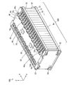
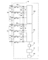
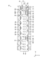
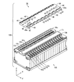
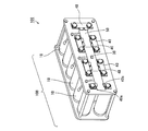
- FIG. 1 is an external perspective view of the battery module 100
- FIG. 2 is a plan view of the battery module 100
- FIG. 3 is an end view of the battery module 100.
- the X direction and the Y direction are directions parallel to the horizontal plane
- the Z direction is a direction orthogonal to the horizontal plane.
- the upward direction is the direction in which the arrow Z faces.
- a plurality of battery cells 10 having a flat, substantially rectangular parallelepiped shape are arranged in the X direction.
- Each battery cell 10 is a secondary battery such as a lithium ion battery or a nickel metal hydride battery.
- the plurality of battery cells 10 are integrally fixed by a pair of end face frames 92, a pair of upper end frames 93 and a pair of lower end frames 94.
- the plurality of battery cells 10, the pair of end face frames 92, the pair of upper end frames 93, and the pair of lower end frames 94 constitute a substantially rectangular parallelepiped battery block 10B.
- the battery block 10B has an upper surface parallel to the XY plane.
- the pair of end face frames 92 have a substantially plate shape and are arranged in parallel to the YZ plane.
- the pair of upper end frames 93 and the pair of lower end frames 94 are arranged so as to extend in the X direction.
- Connection portions for connecting the pair of upper end frames 93 and the pair of lower end frames 94 are formed at the four corners of the pair of end surface frames 92.
- the pair of upper end frames 93 are attached to the upper connection portions of the pair of end surface frames 92, and the lower connection of the pair of end surface frames 92 is performed.
- a pair of lower end frames 94 are attached to the part.
- the plurality of battery cells 10 are integrally fixed in a state of being arranged in the X direction.
- each battery cell 10 has a plus electrode 10a and a minus electrode 10b on the upper surface portion so as to be arranged along the Y direction.
- Each electrode 10a, 10b is provided to be inclined so as to protrude upward (see FIG. 3).
- the battery cells 10 adjacent to one end face frame 92 to the battery cells 10 adjacent to the other end face frame 92 are referred to as first to eighteenth battery cells 10.
- each battery cell 10 is arranged so that the positional relationship between the plus electrode 10 a and the minus electrode 10 b in the Y direction is opposite between adjacent battery cells 10. Further, one electrode 10a, 10b of the plurality of battery cells 10 is arranged in a line along the X direction, and the other electrode 10a, 10b of the plurality of battery cells 10 is arranged in a line along the X direction. Thereby, between two adjacent battery cells 10, the plus electrode 10a of one battery cell 10 and the minus electrode 10b of the other battery cell 10 are adjacent to each other, and the minus electrode 10b of one battery cell 10 and the other The positive electrode 10a of the battery cell 10 is adjacent. In this state, the bus bar 40 is attached to two adjacent electrodes. Thereby, the some battery cell 10 is connected in series.
- a common bus bar 40 is attached to the negative electrode 10b of the first battery cell 10 and the positive electrode 10a of the second battery cell 10.
- a common bus bar 40 is attached to the negative electrode 10b of the second battery cell 10 and the positive electrode 10a of the third battery cell 10.
- a common bus bar 40 is attached to the minus electrode 10b of each odd-numbered battery cell 10 and the plus electrode 10a of the even-numbered battery cell 10 adjacent thereto.
- a common bus bar 40 is attached to the minus electrode 10b of each even-numbered battery cell 10 and the plus electrode 10a of the odd-numbered battery cell 10 adjacent thereto.
- the bus bar 40a is attached to the plus electrode 10a of the first battery cell 10 and the minus electrode 10b of the 18th battery cell 10, respectively.
- the power of the battery module 100 is supplied to the outside by a power line 501 (see FIG. 12 described later) connected to the bus bar 40a.
- a belt-like flexible printed circuit board (hereinafter referred to as an FPC board) 50 extending in the X direction is provided on the upper surface of the battery block 10B.
- FPC board 50 On the FPC board 50, a first circuit 30 and the like for detecting a voltage between terminals of each battery cell 10 are mounted. Details will be described later.
- the FPC board 50 is commonly connected to the plurality of bus bars 40, 40a.
- bus bar 40 for connecting the plus electrode 10a and the minus electrode 10b of two adjacent battery cells 10 is called a two-electrode bus bar 40, and the plus electrode 10a or the minus electrode 10b of one battery cell 10 is called.
- the bus bar 40a for connecting the power line 501 and the power line 501 (see FIG. 12 described later) is referred to as a one-electrode bus bar 40a.
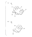
- FIG. 4A is an external perspective view of the bus bar 40 for two electrodes
- FIG. 4B is an external perspective view of the bus bar 40a for one electrode.
- the two-electrode bus bar 40 includes a base portion 41 having a substantially rectangular shape and a pair of attachment pieces 42 that bend and extend from one side of the base portion 41 to one surface thereof.
- a pair of electrode connection holes 43 are formed in the base portion 41.
- the bus bar 40a for one electrode includes a base portion 45 having a substantially square shape and a mounting piece 46 that is bent and extends from one side of the base portion 45 to one surface thereof.
- An electrode connection hole 47 is formed in the base portion 45.
- the bus bars 40, 40a have a configuration in which, for example, nickel plating is applied to the surface of tough pitch copper.
- FIG. 5 is an external perspective view showing a state in which a plurality of bus bars 40, 40a are attached to the FPC board 50.
- FIG. 5 mounting pieces 42 and 46 of a plurality of bus bars 40 and 40 a are attached to the FPC board 50 at predetermined intervals along the X direction.
- a member in which the FPC board 50 and the plurality of bus bars 40, 40a are integrally attached in this manner is referred to as a wiring member 70.
- the wiring member 70 is attached on the battery block 10B.
- the plus electrode 10a and the minus electrode 10b of the adjacent battery cells 10 are the electrodes of each bus bar 40. It is fitted in the connection hole 43. Further, the plus electrode 10a of the first battery cell 10 and the minus electrode 10b of the 18th battery cell 10 are fitted into the electrode connection holes 47 of the bus bar 40a, respectively. Male screws are formed on the plus electrode 10a and the minus electrode 10b. In a state where the bus bars 40 and 40a are fitted into the plus electrode 10a and the minus electrode 10b of the battery cell 10, a nut (not shown) is screwed into the male threads of the plus electrode 10a and the minus electrode 10b.
- the plurality of bus bars 40, 40a are attached to the plus electrode 10a or the minus electrode 10b of the plurality of battery cells 10 by nuts, but the present invention is not limited to this.
- the plurality of bus bars 40, 40a may be attached to the plus electrode 10a or the minus electrode 10b of the plurality of battery cells 10 by welding or the like.
- the wiring member 70 is attached to the battery block 10B, and the FPC board 50 of the wiring member 70 is held in a substantially horizontal posture on the upper surface of the battery block 10B.
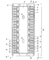
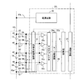
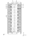
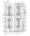
- FIG. 6 is a schematic plan view showing a configuration example of the FPC board 50.
- two first circuits 30, a second circuit 24, an insulating element 25, a discharge circuit 28, and a plurality of PTCs (Positive Temperature Coefficient) are provided on the main surface on the FPC board 50.
- the element 60, the power supply circuit 245, and the connectors 23a and 23b are mounted.
- a plurality of connection terminals 22 and a plurality of connection pads 52 a are formed on the FPC board 50.
- the FPC board 50 has a first mounting region 10G, a second mounting region 12G, and a strip-shaped insulating region 26 on the main surface.
- the second mounting region 12G is formed at a substantially central portion of one end portion of the FPC board 50.
- the insulating region 26 is formed so as to surround the second mounting region 12G.
- the first mounting region 10G is formed in the remaining part of the FPC board 50.
- the first mounting region 10G and the second mounting region 12G are separated from each other by the insulating region 26. Thereby, the first mounting region 10G and the second mounting region 12G are electrically insulated by the insulating region 26.
- the discharge circuit 28, the two first circuits 30, and the plurality of PTC elements 60 are mounted, and a plurality of connection pads 52a and a plurality of connection terminals 22 are formed.
- the plurality of connection pads 52 a are formed at equal intervals along both sides of the main surface of the FPC board 50.
- the plurality of connection pads 52a correspond to the plurality of bus bars 40, 40a in FIGS.
- the discharge circuit 28 and the plurality of connection pads 52a are electrically connected by a connection line (not shown).
- the two first circuits 30 and the plurality of connection terminals 22 are electrically connected by connection lines.
- a plurality of battery cells 10 (see FIG. 1) of the battery module 100 are connected to the first circuit 30 as power supplies for the two first circuits 30.
- the FPC board 50 may have a plurality of convex portions on both sides corresponding to the plus electrode 10a or the minus electrode 10b of the plurality of battery cells 10.
- the plurality of connection pads 52 a are formed on the convex portion of the FPC board 50.
- the plurality of bus bars 40, 40 a are connected to the connection pads 52 a on the convex portion of the FPC board 50.
- the ground pattern GND1L is formed around the mounting region of the low potential side first circuit 30L. Is formed.
- the ground pattern GND1L is held at the lowest potential of half of the plurality of battery cells 10 (9 in this example) on the low potential side (hereinafter referred to as a low potential battery cell group).
- the ground pattern GND1H is formed around the mounting region of the high potential side first circuit 30H. Is formed.
- the ground pattern GND1H is held at the lowest potential of half of the plurality of battery cells 10 on the high potential side (9 in this example) battery cells 10 (hereinafter referred to as a high potential battery cell group).
- the second circuit 24, the power supply circuit 245, and the connectors 23a and 23b are mounted.
- the second circuit 24 and the connector 23a are electrically connected by a connection line.
- the second circuit 24 is connected to the bus 103 of FIG. 13 described later via the connector 23a.
- the power supply circuit 245 and the connector 23b are electrically connected by a connection line.
- the power supply circuit 245 is connected to the switch circuit 107 of FIG. 13 to be described later via the connector 23b.
- the second circuit 24 and the power supply circuit 245 are electrically connected by a connection line.
- a ground pattern GND2 is formed in the second mounting region 12G except for the mounting region of the second circuit 24, the power supply circuit 245, and the connectors 23a and 23b.
- the ground pattern GND2 is held at a reference potential (ground potential) of the non-power battery 12 shown in FIG.
- the insulating element 25 is mounted so as to straddle the insulating region 26.
- the insulating element 25 transmits a signal between the first circuit 30L on the low potential side and the second circuit 24 while electrically insulating the ground pattern GND1L and the ground pattern GND2 from each other.
- a digital isolator or a photocoupler can be used as the insulating element 25.
- a digital isolator is used as the insulating element 25.
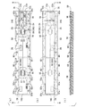
- FIG. 7 is a schematic plan view for explaining the connection between the bus bars 40, 40a, the low potential side first circuit 30L, and the high potential side first circuit 30H.
- the FPC board 50 has a configuration in which a conductor wire 52 and conductor wires 55H and 55L in FIG. 9 to be described later are mainly formed on an insulating layer 50a, and has flexibility and flexibility.
- a conductor wire 52 and conductor wires 55H and 55L in FIG. 9 to be described later are mainly formed on an insulating layer 50a, and has flexibility and flexibility.
- polyimide is used as the material of the insulating layer 50a constituting the FPC board 50
- copper is used as the material of the conductor lines 52, 55H, and 55L.
- the plurality of conductor lines 52 are provided so as to correspond to the plurality of connection pads 52a.
- Each PTC element 60 is arranged on the FPC board 50 so as to be close to each connection pad 52a.
- One end portion of each conductor wire 52 is connected to each connection pad 52a via the PTC element 60.
- the connection pieces 52 and 46 of the bus bars 40 and 40a are connected to the connection pads 52a, for example, by soldering or welding. Thereby, the plurality of bus bars 40, 40 a are fixed to the FPC board 50.
- the plurality of connection terminals 22 are provided so as to correspond to the plurality of conductor wires 52.
- Half of the connection terminals 22 and the low potential side first circuit 30L are electrically connected, and the remaining half of the connection terminals 22 and the high potential side first circuit 30H are electrically connected.
- the other end of each conductor wire 52 of the FPC board 50 is connected to the corresponding connection terminal 22 by, for example, soldering or welding.
- each bus bar 40, 40a is electrically connected to the low potential side first circuit 30L or the high potential side first circuit 30H via the PTC element 60. Thereby, the terminal voltage of each battery cell 10 is detected as will be described later.
- the PTC element 60 has a resistance temperature characteristic in which the resistance value rapidly increases when the temperature exceeds a certain value.
- the temperature of the PTC element 60 may increase due to a current flowing through the short circuit path. In that case, the resistance value of the PTC element 60 increases. This prevents a large current from flowing through the short circuit path including the PTC element 60.
- Each PTC element 60 is preferably arranged in a region between both ends of the corresponding bus bar 40, 40a.
- the area of the FPC board 50 between the adjacent bus bars 40, 40a is easily bent, but the area of the FPC board 50 between both ends of each bus bar 40, 40a is fixed to the bus bars 40, 40a. Therefore, it is kept relatively flat. Therefore, each PTC element 60 is disposed in the region of the FPC board 50 between both end portions of each bus bar 40, 40a, thereby ensuring sufficient connectivity between the PTC element 60 and the conductor wire 52. Moreover, the influence (for example, change of the resistance value of the PTC element 60) on each PTC element 60 by the bending of the FPC board 50 is suppressed.
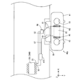
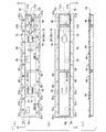
- FIG. 8 is an enlarged plan view showing a part of the voltage / current bus bar 40 y and the FPC board 50. As shown in FIG. 8, the FPC board 50 further includes an amplifier circuit 410.
- solder patterns H1 and H2 are formed in parallel with each other at regular intervals.
- the solder pattern H1 is disposed between the two electrode connection holes 43 in the vicinity of one electrode connection hole 43
- the solder pattern H2 is disposed between the electrode connection holes 43 in the vicinity of the other electrode connection hole 43.
- the resistance formed between the solder patterns H1 and H2 in the voltage / current bus bar 40y is referred to as a current detection shunt resistance RS.
- the solder pattern H1 of the voltage / current bus bar 40y is connected to one input terminal of the amplifier circuit 410 via the conductor line 51 and the conductor line 52.
- the solder pattern H2 of the voltage / current bus bar 40y is connected to the other input terminal of the amplifier circuit 410 via the conductor line 51, the PTC element 60, and the conductor line 52.
- the output terminal of the amplifier circuit 410 is connected to one connection terminal 22. Thereby, the low potential side first circuit 30L or the high potential side first circuit 30H detects the voltage between the solder patterns H1 and H2 based on the output voltage of the amplifier circuit 410.
- the voltage between the solder patterns H1, H2 detected by the low potential side first circuit 30L or the high potential side first circuit 30H is applied to the second circuit 24 of FIG. As will be described later, the second circuit 24 calculates the value of the current flowing through the plurality of battery cells 10 based on the voltage between the solder patterns H1 and H2.
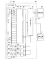
- FIG. 9 is a block diagram showing electrical connection on the FPC board 50 of FIG. In FIG. 9, illustration of the connection terminal 22 of FIGS. 6 and 7 is omitted.
- the low potential side first circuit 30L corresponds to the low potential side battery cell group 10L.
- the high potential side first circuit 30H corresponds to the high potential side battery cell group 10H.
- the low potential side first circuit 30L is electrically connected to the bus bars 40, 40a of the low potential side battery cell group 10L via the discharge circuit 28, the plurality of conductor wires 52 and the PTC element 60.
- the high potential side first circuit 30H is electrically connected to the bus bars 40, 40a of the high potential side battery cell group 10H via the discharge circuit 28, the plurality of conductor lines 52 and the PTC element 60.
- the low potential side first circuit 30L detects the terminal voltage of each of the plurality of battery cells 10 in the low potential side battery cell group 10L.
- the high potential side first circuit 30H detects the terminal voltage of each of the plurality of battery cells 10 in the high potential side battery cell group 10H.
- the low potential side first circuit 30L is electrically connected to the bus bar 40 of the battery cell 10 having the highest potential among the battery cells 10 of the low potential side battery cell group 10L through the conductor line 55L.
- the reference potential (ground potential) of the low potential side first circuit 30L is held at the lowest potential of the plurality of battery cells 10 in the low potential side battery cell group 10L. Thereby, electric power is supplied to the low potential side first circuit 30L from the plurality of battery cells 10 of the low potential side battery cell group 10L.
- the high potential side first circuit 30H is electrically connected to the bus bar 40a of the battery cell 10 having the highest potential among the battery cells 10 of the high potential side battery cell group 10H through the conductor line 55H.
- the reference potential (ground potential) of the high potential side first circuit 30H is held at the lowest potential of the plurality of battery cells 10 in the high potential side battery cell group 10H. Thereby, electric power is supplied to the high potential battery cell group 10H from the plurality of battery cells 10 in the high potential battery cell group 10H.
- the discharge circuit 28 corresponding to the first circuit 30L on the low potential side includes a plurality of sets (9 sets in this example) of series circuits each including the resistor R and the switching element SW. Between each two adjacent bus bars 40, a set of series circuits including a resistor R and a switching element SW is connected. A pair of series circuits including a resistor R and a switching element SW is also connected between each two adjacent bus bars 40 and 40a.
- the switching element SW is turned on and off by the second circuit 24 via the low potential side first circuit 30L. In the normal state, the switching element SW is turned off.
- the ON / OFF of the switching element SW is controlled by the second circuit 24 via the low-potential side first circuit 30L and the high-potential side first circuit 30H. Except for the discharge circuit 28 corresponding to the first circuit 30L on the low potential side.
- FIG. 10 is a block diagram showing a configuration of the low potential side first circuit 30L of FIG.
- the low-potential-side first circuit 30L is composed of, for example, an ASIC (Application Specific Integrated Circuit).
- the low potential side first circuit 30L includes a detection unit 20, a control unit 31, a communication circuit 32, an equalization control circuit 33, and a power supply circuit 35.
- Reference potential hereinafter referred to as a component of the low potential side first circuit 30L
- (Ground potential) is held at the lowest potential of the plurality of battery cells 10 in the low potential side battery cell group 10L.
- the detection unit 20 includes a multiplexer 20a, an A / D (analog / digital) converter 20b, and a plurality of differential amplifiers 20c.
- Each differential amplifier 20c of the detection unit 20 has two input terminals and an output terminal.
- Each differential amplifier 20c differentially amplifies the voltage input to the two input terminals, and outputs the amplified voltage from the output terminal.
- each differential amplifier 20c Two input terminals of each differential amplifier 20c are connected to two adjacent bus bars 40 or two adjacent bus bars 40 of the plurality of battery cells 10 of the low potential side battery cell group 10L via the conductor line 52 and the PTC element 60.
- 40a is electrically connected.
- the voltage between the two adjacent bus bars 40 or the voltage between the two adjacent bus bars 40 and 40a is differentially amplified by each differential amplifier 20c.
- the output voltage of each differential amplifier 20c corresponds to the terminal voltage of each battery cell 10 in the low potential side battery cell group 10L.
- the voltages output from the plurality of differential amplifiers 20c are supplied to the multiplexer 20a.
- the multiplexer 20a sequentially outputs the terminal voltages supplied from the plurality of differential amplifiers 20c to the A / D converter 20b.
- the A / D converter 20b converts the terminal voltage output from the multiplexer 20a into a digital value.
- the control unit 31 is connected to the detection unit 20, the communication circuit 32, and the equalization control circuit 33.
- the communication circuit 32 has a communication function and is communicably connected to the second circuit 24 of FIG. 9 via the insulating element 25 of FIG. Further, the communication circuit 32 is connected to be communicable with the high potential side first circuit 30H of FIG.
- the control unit 31 acquires the digital value of the terminal voltage of each battery cell 10 of the low potential side battery cell group 10L from the A / D converter 20b of the detection unit 20. Further, as will be described later, the control unit 31 acquires the digital value of the terminal voltage of each battery cell 10 of the high potential side battery cell group 10H from the high potential side first circuit 30H via the communication circuit 32. Further, the control unit 31 isolates the digital value of the terminal voltage of each battery cell 10 of the low potential side battery cell group 10L and the digital value of the terminal voltage of each battery cell 10 of the high potential side battery cell group 10H from the communication circuit 32. It transmits to the 2nd circuit 24 via the element 25 (refer FIG. 9). The control unit 31 receives a command for equalization processing, which will be described later, transmitted from the second circuit 24 via the insulating element 25 and the communication circuit 32, and gives the command to the equalization control circuit 33.
- the equalization control circuit 33 performs the process of equalizing the state of charge of the battery cell 10 by turning on and off the switching element SW of the discharge circuit 28 based on a command from the second circuit 24.
- the power supply circuit 35 is electrically connected to the bus bar 40 having the highest potential of the low-potential side battery cell group 10L through the conductor line 55L.
- the power supply circuit 35 steps down or boosts the input voltage to a predetermined voltage (for example, 5 V) and outputs it.
- the components of the low potential side first circuit 30 ⁇ / b> L operate with the voltage output from the power supply circuit 35.
- Reference potential (hereinafter, referred to as a component of the high potential side first circuit 30H) of the detection unit 20, the control unit 31, the communication circuit 32, the equalization control circuit 33, and the power supply circuit 35 of the high potential side first circuit 30H. (Ground potential) is held at the lowest potential of the plurality of battery cells 10 in the high-potential side battery cell group 10H.
- the power supply circuit 35 is electrically connected to the bus bar 40a of the battery cell 10 having the highest potential among the plurality of battery cells 10 of the high potential side battery cell group 10H by a conductor line 55H instead of the conductor line 55L of FIG. .
- the communication circuit 32 of the high potential side first circuit 30H is communicably connected to the communication circuit 32 (see FIG. 10) of the low potential side first circuit 30L.
- the control unit 31 of the high potential side first circuit 30H passes through the communication circuit 32 of the high potential side first circuit 30H, the communication circuit 32 of the low potential side first circuit 30L, and the insulating element 25 (see FIG. 9).
- the digital value of the terminal voltage of each battery cell 10 of the high potential side battery cell group 10H can be transmitted to the second circuit 24.
- FIG. 11 is a block diagram showing the configuration of the second circuit 24 of FIG.
- the second circuit 24 includes a processing unit 241, a storage unit 242, and a communication interface 244.
- the processing unit 241, the storage unit 242, and the communication interface 244 operate with a voltage (for example, 5V) output from the power supply circuit 245 of FIG.
- the processing unit 241 includes a CPU (Central Processing Unit), for example, and is connected to the storage unit 242.
- the processing unit 241 is connected to a plurality of thermistors 11 shown in FIG. Thereby, the processing unit 241 acquires the temperature of the battery module 100.
- the processing unit 241 functions to process the terminal voltage, current, and other information transmitted from the detection unit 20 (see FIGS. 9 and 10) of the low potential side first circuit 30L and the high potential side first circuit 30H.
- the processing unit 241 calculates the charge amount of each battery cell 10, the current flowing through the plurality of battery cells 10, and the like.
- the terminal voltage of the battery cell, the current flowing through the plurality of battery cells 10 and the temperature of the battery module 100 are referred to as cell information. Details of the calculation of the current flowing through the plurality of battery cells 10 will be described later.
- the storage unit 242 includes a non-volatile memory such as an EEPROM (electrically erasable and programmable read-only memory).
- EEPROM electrically erasable and programmable read-only memory
- the value of the shunt resistance RS between the solder patterns H1 and H2 in the voltage / current bus bar 40y of FIG. 8 is stored in advance.
- the processing unit 241 includes a communication circuit 246 having a communication function.
- the processing unit 241 is communicably connected to the communication circuit 32 (see FIG. 10) of the low potential side first circuit 30L via the insulating element 25 (see FIG. 9).
- the processing unit 241 of the second circuit 24 in FIG. 11 includes a shunt resistor in which the voltage between the solder patterns H1 and H2 given from the low potential side first circuit 30L or the high potential side first circuit 30H is stored in the storage unit 242. By dividing by the value of RS, the value of the current flowing through the voltage / current bus bar 40y is calculated.
- the processing unit 241 gives various commands for equalization processing to the control unit 31 (see FIGS. 9 and 10) of the low potential side first circuit 30L and the high potential side first circuit 30H.
- a communication interface 244 is connected to the processing unit 241.
- the communication interface 244 is an RS-485 standard serial communication interface, for example.
- the communication circuit 246 performs RS-485 standard serial communication with the battery ECU 101 of FIG. 12 described later, but is not limited thereto.
- the communication circuit 246 may perform serial communication of other standards with the battery ECU 101, and may perform CAN (Controller Area Network) communication with the battery ECU 101.
- the second circuit 24 may be a microcomputer having functions of the processing unit 241, the storage unit 242, and the communication interface 244.
- the cell information is transmitted to the battery ECU 101 by the communication circuit 246 of the second circuit 24, or various information and commands are received from the battery ECU 101.
- the second circuit 24 operates by electric power supplied from the non-power battery 12 shown in FIG. Thereby, even when the voltage of the battery cell 10 of any battery module 100 of the battery system 500 is lowered, the battery module 100 can communicate with the battery ECU 101.
- the second circuit 24 of each battery module 100 calculates the charge amount of each battery cell 10 based on the cell information.
- the second circuit 24 performs charge / discharge control of each battery cell 10 based on the terminal voltage value of each battery cell 10 transmitted from the low potential side first circuit 30L and the high potential side first circuit 30H.
- the second circuit 24 of each battery module 100 detects an abnormality of each battery module 100 based on the cell information.
- the abnormality of the battery module 100 is, for example, overdischarge, overcharge, or temperature abnormality of the battery cell 10.
- each second circuit 24 provides the battery ECU 101 with a calculation result of the charge amount of each battery cell 10 and detection results such as overdischarge, overcharge, and temperature abnormality of the battery cell 10.
- the second circuit 24 of each battery module 100 calculates the amount of charge of each battery cell 10 described above, detects battery cell 10 overdischarge, overcharge, temperature abnormality, and the like and performs equalization processing.
- the battery ECU 101 may perform various commands for calculation of the charge amount of each battery cell 10, detection of overdischarge, overcharge and temperature abnormality of the battery cell 10, and equalization processing.
- the low potential side first circuit 30L (see FIG. 9) and the second circuit 24 are communicably connected while being electrically insulated by the insulating element 25 (see FIG. 9). Further, the high potential side first circuit 30H (see FIG. 9) and the second circuit 24 are connected to each other via the low potential side first circuit 30L while being electrically insulated.
- a plurality of battery cells 10 can be used as the power source for the low potential side first circuit 30L and the high potential side first circuit 30H, and the non-power battery 12 (see FIG. 12 described later) as the power source for the second circuit 24. ) Can be used.
- the second circuit 24 can be stably operated independently from the low potential side first circuit 30L and the high potential side first circuit 30H.
- FIG. 12 is a block diagram showing a configuration of a battery system using the battery module according to the present embodiment.
- the battery system 500 includes a plurality of battery modules 100 (four in this example), a battery ECU 101 and a contactor 102.
- the plurality of battery modules 100 are connected to the battery ECU 101 via the bus 103.
- the battery ECU 101 of the battery system 500 is connected to the main control unit 300 of the electric vehicle via the bus 104.
- the plurality of battery modules 100 of the battery system 500 are connected to each other through the power line 501.
- Each battery module 100 includes a plurality of (four in this example) thermistors 11 together with the battery cells 10 and the FPC board 50.
- all the battery cells 10 of the plurality of battery modules 100 are connected in series.
- the power supply line 501 connected to the highest potential positive electrode 10a (see FIG. 1) and the power supply line 501 connected to the lowest potential negative electrode 10b (see FIG. 1) of the plurality of battery modules 100 are connected to the contactor 102.
- a load such as a motor of an electric vehicle.
- the battery ECU 101 detects an abnormality of the battery module 100 from the second circuit 24 of FIG. 11, the battery ECU 101 turns off the contactor 102.
- MPU 106 (see FIG. 13 described later) of battery ECU 101 controls on / off of contactor 102, but the present invention is not limited to this.
- the second circuit 24 of the battery module 100 may control on and off of the contactor 102.
- the battery ECU 101 gives the main controller 300 the amount of charge of each battery module 100 (the amount of charge of the battery cell 10).
- the main control unit 300 controls the power of the electric vehicle (for example, the rotational speed of the motor) based on the amount of charge.
- the main control unit 300 controls each power generation device (not shown) connected to the power line 501 to charge each battery module 100.
- the power generation device is a motor connected to the power supply line 501 described above, for example.
- the motor converts the electric power supplied from the battery system 500 during acceleration of the electric vehicle into motive power for driving drive wheels (not shown).
- the motor generates regenerative power when the electric vehicle is decelerated. Each battery module 100 is charged by this regenerative power.
- FIG. 13 is a block diagram showing the connection between the battery module and the battery ECU.
- the battery ECU 101 has a printed circuit board 105.
- a microprocessor (MPU) 106, a switch circuit 107, and a power supply circuit 108 are mounted on the printed circuit board 105.
- Other circuits such as a contactor control circuit for turning on and off the contactor 102 of FIG. 12 are also mounted on the printed circuit board 105.
- the power supply circuit 108 steps down the voltage supplied from the non-power battery 12 via the switch circuit 107 and supplies it to the MPU 106. That is, the non-power battery 12 is used as a power source for the MPU 106.
- the non-power battery 12 is a lead storage battery.
- the switch circuit 107 of the printed circuit board 105 is connected to the power supply circuit 245 of the FPC board 50 through the connector 23b of FIG. On / off of the switch circuit 107 is controlled by the MPU 106.
- the switch circuit 107 When the switch circuit 107 is on, power from the non-power battery 12 is supplied to the second circuit 24 via the switch circuit 107 and the power supply circuit 245 of the FPC board 50. Thereby, the second circuit 24 operates. That is, the non-power battery 12 is used as a power source for the second circuit 24.
- the second circuit 24 is connected to the bus 103.
- the MPU 106 is connected to the bus 103. Thereby, MPU106 of battery ECU101 and the 2nd circuit 24 of each battery module 100 are connected so that communication is possible.
- the MPU 106 transmits various commands for equalization processing to the low potential side first circuit 30L and the high potential side first circuit 30H via the bus 103, the second circuit 24, and the insulating element 25.
- the low potential side first circuit 30L and the high potential side first circuit 30H have a function of calculating SOH (StateSOf Health: life of the battery cell 10) and SOC (State Of Charge: state of charge). Also good.
- the second circuit 24 acquires the information of the battery cell 10 such as SOH and SOC from the low potential side first circuit 30L or the high potential side first circuit 30H to the MPU 106 via the bus 103, and the acquired information It transmits to MPU106. Further, the second circuit 24 transmits failure determination information of the FPC board 50 to the MPU 106.
- the MPU 106 may be provided in the main control unit 300 in FIG. Further, the functions of the MPU 106 may be provided in a distributed manner in the second circuit 24 and the main control unit 300. Further, the MPU 106 is communicably connected to the main control unit 300 (see FIG. 12) of the electric vehicle via the bus 104 (see FIG. 12).
- the low potential side first circuit 30L and the high potential side first circuit 30H are mounted on the FPC board 50 provided on the upper surface of the battery block 10B.
- Connection pads 52a are formed along both sides of the FPC board 50, and the bus bars 40, 40a are connected to the connection pads 52a.
- the bus bars 40, 40a and the low potential side first circuit 30L or the high potential side first circuit 30H are electrically connected by the conductor wire 52 of the FPC board 50.
- the FPC board 50 has flexibility. Therefore, there is a displacement between the plus electrode 10a or minus electrode 10b of each battery cell 10 and the bus bars 40, 40a connected to the FPC board 50 due to an assembly error of the battery block 10B or a dimensional error of the plurality of battery cells 10. Even in this case, the FPC board 50 is partially deformed, so that the misalignment is absorbed. Thereby, the bus bars 40 and 40a can be connected to the plus electrode 10a or the minus electrode 10b of each battery cell 10 accurately and easily. As a result, the work efficiency in the assembly process of the battery module 100 is improved, and the reliability of the battery module 100 is improved.
- the bus bars 40 and 40a are connected to the battery cells 10 plus electrode 10a or the minus electrode 10b and a displacement occurs between the plus electrodes 10a or minus electrodes 10b of the battery cells 10 and the bus bars 40 and 40a.
- the position shift is absorbed by the FPC board 50 being partially deformed. Thereby, the FPC board 50 is prevented from being damaged. As a result, the reliability of the battery module 100 is improved.
- the assembly accuracy of the battery block 10B and the dimensional accuracy of the plurality of battery cells 10 are alleviated. Thereby, the manufacturing yield of the battery module 100 is improved. Furthermore, it is not necessary to separately provide a member or a structure for absorbing displacement between the plus electrode 10a or the minus electrode 10b of the plurality of battery cells 10 and the bus bars 40, 40a. Therefore, the configuration of the battery module 100 is prevented from becoming complicated. As a result, the cost of the battery module 100 can be reduced.
- Second Embodiment A battery module according to a second embodiment will be described while referring to differences from the battery module 100 according to the first embodiment.
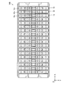
- FIG. 14 is a plan view of the battery block 10B according to the second embodiment.
- the battery cell 10 in the present embodiment has a gas vent valve 10v at the center of the upper surface portion.
- the gas inside the battery cell 10 is discharged from the gas vent valve 10v of the battery cell 10. Thereby, the excessive raise of the pressure inside the battery cell 10 is prevented.
- FIG. 15 is a plan view of the wiring member 70 according to the second embodiment. As shown in FIG. 15, in the FPC board 50 of the wiring member 70 in the present embodiment, the plurality of battery cells of FIG. 14 are equally spaced so that the plurality of holes H are arranged in the center along the length direction. 10 degassing valves 10v are formed so as to correspond respectively.
- the second mounting region 12G is formed at a substantially central portion of one end of the FPC board 50.
- the insulating region 26 is formed so as to surround the second mounting region 12G and not overlap with the plurality of holes H.
- the first mounting region 10G is formed in the remaining part of the FPC board 50.
- the discharge circuit 28, the low potential side first circuit 30L, the high potential side first circuit 30H, and the plurality of PTC elements 60 are mounted so as not to overlap the plurality of holes H.
- a plurality of connection pads 52a and a plurality of connection terminals 22 are formed.
- the low potential side first circuit 30L is excluded except for the mounting region of the low potential side first circuit 30L and the formation region of the connection terminal 22 so as not to overlap with the plurality of holes H.
- a ground pattern GND1L is formed around the mounting region.
- the high potential side first circuit 30H is excluded except for the mounting region of the high potential side first circuit 30H and the formation region of the connection terminal 22 so as not to overlap with the plurality of holes H.
- a ground pattern GND1H is formed around the mounting region.
- the second circuit 24, the power supply circuit 245, and the connectors 23a and 23b are mounted in the second mounting region 12G so as not to overlap with the plurality of holes H. Further, in the second mounting region 12G, the second circuit 24, the power supply circuit 245, and the second circuit 24, except for the mounting region of the connectors 23a and 23b, so as not to overlap with the plurality of holes H.
- a ground pattern GND2 is formed around the connectors 23a and 23b.
- the insulating element 25 is mounted so as not to overlap the plurality of holes H and straddle the insulating region 26.
- FIG. 16 is a plan view of the battery module 100 according to the second embodiment.
- the plurality of holes H of the FPC board 50 are respectively positioned above the gas vent valves 10 v of the plurality of battery cells 10.
- the pressure inside the battery cell 10 rises to a predetermined value
- the gas inside the battery cell 10 is not obstructed by the FPC board 50 of the wiring member 70, and the plurality of holes H are opened from the gas vent valve 10 v. It is possible to discharge to the outside through.
- FIG. 17 is a plan view of the battery block 10B according to the third embodiment. As shown in FIG. 17, in the present embodiment, the plurality of bus bars 40, 40a are connected in advance to the plus electrode 10a or the minus electrode 10b of the plurality of battery cells 10 by soldering or welding in advance.
- FIG. 18 is a plan view of the FPC board 50 according to the third embodiment.
- a plurality of welding members 52b are respectively attached in advance to the plurality of connection pads 52a of the FPC board 50 in the present embodiment.
- the FPC board 50 is disposed on the upper surface of the battery block 10B so that the welding members 52b attached to the plurality of connection pads 52a overlap the plurality of bus bars 40, 40a, respectively. Thereafter, the plurality of welding members 52b are welded to the plurality of bus bars 40, 40a, whereby the connection pads 52a of the FPC board 50 are connected to the plurality of bus bars 40, 40a, respectively.
- connection pad 52a can be easily positioned on the bus bars 40, 40a connected to the plus electrode 10a or the minus electrode 10b of the plurality of battery cells 10. it can. Thereby, the battery module 100 can be easily assembled.
- the plurality of bus bars 40, 40a are attached to the plus electrode 10a or the minus electrode 10b of the plurality of battery cells 10 by welding, but the present invention is not limited to this.
- the plurality of bus bars 40, 40a may be attached to the plus electrode 10a or the minus electrode 10b of the plurality of battery cells 10 by nuts.
- FIG. 19 is a plan view and a cross-sectional view of the FPC board 50 according to the fourth embodiment.
- 19 (a) is a plan view of the main surface of the FPC board 50
- FIG. 19 (b) is a plan view of the back surface of the FPC board 50
- FIG. 19 (c) is a plan view of FIGS. 19 (a) and 19 (b). 2 is a cross-sectional view of the FPC board 50 of FIG.
- the configuration of the main surface of the FPC board 50 in the present embodiment is the same as the configuration of the main surface of the FPC board 50 in FIG.
- the FPC board 50 in this embodiment has a reinforcing plate 56 on the back surface except for a constant width region at the peripheral edge to which the plurality of bus bars 40, 40a are connected. Are joined.
- the reinforcing plate 56 is bonded to the FPC board 50 with an adhesive or the like.
- the reinforcing plate 56 is made of, for example, glass epoxy resin and has higher rigidity than the FPC board 50. Thereby, the durability of the FPC board 50 can be improved while ensuring the flexibility of the peripheral region to which the plurality of bus bars 40, 40a are connected.
- the reinforcing plate 56 is preferably formed of a material having a thermal expansion coefficient comparable to that of the insulating layer 50a (see FIG. 7) constituting the FPC board 50. As a result, even if the dimension of the reinforcing plate 56 changes due to a temperature change, the dimension of the FPC board 50 changes in the same manner, so that the reinforcing board 56 is prevented from peeling off from the FPC board 50. Furthermore, the reinforcing plate 56 is preferably formed of a non-conductive material. Thereby, even when the reinforcement board 56 contacts the battery block 10B, it is prevented that the some battery cell 10 short-circuits.
- the reinforcing plate 56 is formed of a glass epoxy resin, but other materials such as a polyetheretherketone (PEEK) resin, a polyphenylsulfone (PPSU) resin, or a polyethersulfone (PES) resin are used. It may be formed of a material.
- PEEK polyetheretherketone
- PPSU polyphenylsulfone
- PES polyethersulfone
- FIG. 20 is a plan view and a cross-sectional view of the FPC board 50 according to the fifth embodiment.
- 20 (a) is a plan view of the main surface of the FPC board 50
- FIG. 20 (b) is a plan view of the back surface of the FPC board 50
- the configuration of the main surface of the FPC board 50 in the present embodiment is the same as the configuration of the main surface of the FPC board 50 in FIG.
- the FPC board 50 in the present embodiment includes a plurality of (books) on the back surface except for a constant width region at the peripheral edge to which the plurality of bus bars 40, 40a are connected.
- three reinforcing plates 56 are joined. Each portion of the plurality of reinforcing plates 56 is formed on the FPC board 50 on which the low potential side first circuit 30L, the high potential side first circuit 30H, the second circuit 24, the insulating element 25, the discharge circuit 28, and the power supply circuit 245 are mounted. Arranged to reinforce the area.
- the low potential side first circuit 30L, the high potential side first circuit 30H, the second circuit 24 of the FPC board 50 are secured while ensuring the flexibility of the peripheral region to which the plurality of bus bars 40, 40a are connected.
- the durability of the region where the insulating element 25, the discharge circuit 28, and the power supply circuit 245 are mounted can be improved.
- the FPC board 50 can be bent in the region between the reinforcing plates 56. Thereby, the degree of freedom of deformation of the FPC board 50 is improved. As a result, the displacement between the positive electrode 10a or the negative electrode 10b of each battery cell 10 and the bus bars 40, 40a connected to the FPC board 50 is sufficiently absorbed.
- FIG. 21 is a plan view and a cross-sectional view of the FPC board 50 in the sixth embodiment.
- 21 (a) is a plan view of the main surface of the FPC board 50
- FIG. 21 (b) is a plan view of the back surface of the FPC board 50
- the configuration of the main surface of the FPC board 50 in the present embodiment is the same as the configuration of the main surface of the FPC board 50 in FIG.
- the FPC board 50 in the present embodiment has a reinforcing plate 56 on the back surface except for a constant width region at the peripheral edge to which the plurality of bus bars 40, 40a are connected. Are joined.
- the reinforcing plate 56 in the present embodiment has a rectangular frame-like structure such as “B”.
- the durability of the FPC board 50 can be improved while ensuring the flexibility of the peripheral area to which the plurality of bus bars 40, 40a are connected. Moreover, since the reinforcing plate 56 does not exist in the center part of the FPC board 50, the battery module 100 according to the present embodiment is reduced in weight compared to the battery module 100 according to the fourth embodiment.
- FIG. 22 is a plan view and a cross-sectional view of the FPC board 50 according to the seventh embodiment.
- 22 (a) is a plan view of the main surface of the FPC board 50
- FIG. 22 (b) is a plan view of the back surface of the FPC board 50
- the configuration of the main surface of the FPC board 50 in the present embodiment is the same as the configuration of the main surface of the FPC board 50 in FIG.
- the FPC board 50 in the present embodiment includes a plurality of (books) on the back surface except for a constant width region at the peripheral edge to which the plurality of bus bars 40, 40a are connected.
- three reinforcing plates 56 are joined.
- the reinforcing plate 56 in the present embodiment has a rectangular frame-like structure such as “B”.
- Each portion of the plurality of reinforcing plates 56 is formed on the FPC board 50 on which the low potential side first circuit 30L, the high potential side first circuit 30H, the second circuit 24, the insulating element 25, the discharge circuit 28, and the power supply circuit 245 are mounted. Arranged to reinforce the area.
- the low potential side first circuit 30L, the high potential side first circuit 30H, the second circuit 24 of the FPC board 50 are secured while ensuring the flexibility of the peripheral region to which the plurality of bus bars 40, 40a are connected.
- the durability of the region where the insulating element 25, the discharge circuit 28, and the power supply circuit 245 are mounted can be improved.
- the reinforcing plate 56 does not exist in the center part of the FPC board 50, the battery module 100 according to the present embodiment is lighter than the battery module 100 according to the fifth embodiment.
- the FPC board 50 can be bent in the region between the reinforcing plates 56. Thereby, the degree of freedom of deformation of the FPC board 50 is improved. As a result, the displacement between the positive electrode 10a or the negative electrode 10b of each battery cell 10 and the bus bars 40, 40a connected to the FPC board 50 is sufficiently absorbed.
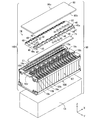
- FIG. 23 is an exploded perspective view showing the configuration of the battery module 100 according to the eighth embodiment.
- the battery module 100 further includes a gas duct 71.
- the gas duct 71 is provided on the upper surface of the battery block 10B so as to cover the gas vent valves 10v (see FIG. 14) of the plurality of battery cells 10.
- the wiring member 70 is mounted on the battery block 10B as in the first embodiment.
- the gas discharged from the gas vent valve 10v of the battery cell 10 is released to the outside through the gas duct 71 without being obstructed by the wiring member 70. Therefore, the gas can be discharged from the gas vent valve 10v to the outside without providing a plurality of holes H (see FIG. 15) in the FPC board 50 of the wiring member 70.
- FIG. 10 A battery module according to the ninth embodiment will be described while referring to differences from the battery module 100 according to the eighth embodiment.
- battery module 100 is arranged in a casing (housing) CA having an open top.
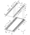
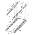
- FIG. 24 is an exploded perspective view showing the configuration of the battery module 100 according to the ninth embodiment.
- the battery module 100 further includes a lid member 80.
- the lid member 80 is made of an insulating material such as resin and has a rectangular plate shape.
- a gas duct 71, a wiring member 70, and a lid member 80 are sequentially arranged on the upper surface of the battery block 10B.
- the wiring member 70 is attached to the lower surface of the lid member 80, and the gas duct 71 is attached to the lower surface of the wiring member 70.
- Battery block 10B is housed in casing CA, and lid member 80 is fitted to casing CA so as to close the opening of casing CA. Thereby, the battery box BB that houses the battery module 100 is formed.
- FIG. 25 is a perspective view of the lid member 80 of FIG. 24 as viewed obliquely from below.
- FIG. 26 is a perspective view of the lid member 80 of FIG. 24 as viewed obliquely from above.
- the side 80a of the lid member 80 is along the side E1 (see FIG. 24) on one side of the battery block 10B (see FIG. 24), and the side 80b of the lid 80 is the side E2 on the other side of the battery block 10B (see FIG. 24). See).
- the surface of the lid member 80 facing the battery block 10B is called a back surface
- the surface of the lid member 80 on the opposite side is called a front surface. In this example, the surface of the lid member 80 is directed upward.
- a plurality of recesses 81 and 82 are provided on the back surface of the lid member 80 so as to extend along the side 80 a and the side 80 b of the lid member 80.
- nine recesses 81 are provided along the side 80 a of the lid member 80.
- One recess 82, eight recesses 81, and another one recess 82 are provided along the side 80 b of the lid member 80.
- the concave portions 81 and 82 have a substantially rectangular shape, and the length of the concave portion 81 in the X direction is larger than the length of the concave portion 82 in the X direction.
- the shape and length of the recess 81 are substantially equal to the shape and length of the bus bar 40, and the shape and length of the recess 82 are substantially equal to the shape and length of the bus bar 40a.
- a plurality of openings 83 are formed so as to penetrate from the bottom surfaces of the plurality of recesses 81 and 82 to the surface of the lid member 80 (see FIG. 26). Two openings 83 (see FIG. 26) are formed in each recess 81, and one opening 83 (see FIG. 26) is formed in each recess 82.
- the recess 81 and the opening 83 provided along the side 80a of the lid member 80 are referred to as the recess 81 on the side 80a and the opening 83 on the side 80a, respectively, and along the side 80b of the lid 80.
- the recesses 81 and 82 and the opening 83 thus provided are referred to as the recesses 81 and 82 on the side 80b side and the opening 83 on the side 80b side, respectively.
- the bus bar 40 of the wiring member 70 is fitted into the recess 81 of the lid member 80, and the bus bar 40 a of the wiring member 70 is fitted into the recess 82.
- the electrode connection hole 43 of the bus bar 40 is exposed to the surface side of the lid member 80 in the opening 83.
- the electrode connection hole 47 of the bus bar 40 a is exposed to the surface side of the lid member 80 in the opening 83 in a state where the bus bar 40 a is fitted in the recess 82.
- the FPC fitting portion 84 is formed so as to extend in the X direction between the plurality of recesses 81 on the side 80a side and the plurality of recesses 81, 82 on the side 80b side.
- the FPC board 50 of the wiring member 70 is fitted into the FPC fitting portion 84.
- a plurality of pairs of connection grooves 85 are formed so as to extend from the plurality of recesses 81 to the FPC fitting portion 84, respectively.
- a plurality of connection grooves 86 are formed so as to extend from the plurality of recesses 82 on the side 80b side to the FPC fitting portion 84, respectively.
- a pair of attachment pieces 42 of the plurality of bus bars 40 are respectively disposed in the plurality of pairs of connection grooves 85. In the plurality of connection grooves 86, the attachment pieces 46 of the plurality of bus bars 40a are respectively arranged.
- the gas duct 71 (see FIG. 24) is joined to the FPC board 50 with an adhesive or the like. In this way, the gas duct 71 and the wiring member 70 are attached to the lid member 80. In this state, the lid member 80 is attached to the upper surface of the battery block 10B.
- the plus electrodes 10a (see FIG. 24) and the minus electrodes 10b (see FIG. 24) of the plurality of battery cells 10 are fitted into the electrode connection holes 43 of the plurality of bus bars 40.
- the positive electrodes 10a or the negative electrodes 10b of the plurality of battery cells 10 are inserted into the electrode connection holes 47 of the plurality of bus bars 40a.
- the gas duct 71 is disposed on the upper surface of the battery block 10B so as to cover the gas vent valves 10v of the plurality of battery cells 10.
- a nut (not shown) is screwed to the male threads of the plus electrode 10a and the minus electrode 10b. Thereby, adjacent battery cells 10 are electrically connected via the bus bar 40. As a result, the plurality of battery cells 10 are connected in series.
- the gas duct 71 and the wiring member 70 are integrally provided on the lid member 80. Therefore, the battery module 100 can be easily assembled by attaching the lid member 80 to the battery block 10B.
- the strength of the battery module 100 is improved. Further, since the battery block 10B of the battery module 100 is fixed to the casing CA of the battery box BB and the lid member 80 is fitted to the casing CA, the battery block 10B and the lid member 80 can be reliably fixed. .
- the opening of the casing CA is closed by the lid member 80. Therefore, the inside of the battery box BB may be molded with resin. In this case, condensation of the battery cell 10 can be prevented. Further, the resin molded in the battery box BB can affect the heat conduction characteristics of the battery module 100. For example, by molding the inside of the battery box BB with a resin having a higher thermal conductivity than air, the heat in the battery box BB can be released to the outside. On the other hand, by molding the inside of the battery box BB with a resin having a thermal conductivity lower than that of air, the inflow of heat from the outside into the battery box BB can be blocked.
- the inside of the battery box BB can be exhausted by providing a hole in at least one of the casing CA and the lid member 80.
- the gas duct 71 may not be provided in the battery module 100.
- FIG. 27 is an exploded perspective view showing the configuration of the battery module 100 according to the tenth embodiment. As shown in FIG. 27, the gas duct 71, the lid member 80, and the wiring member 70 are sequentially arranged on the upper surface of the battery block 10B. The wiring member 70 is attached to the upper surface of the lid member 80, and the gas duct 71 is attached to the lower surface of the lid member 80.
- FIG. 28 is a perspective view of the lid member 80 of FIG. 27 as viewed obliquely from below.
- FIG. 29 is a perspective view of the lid member 80 of FIG. 27 as viewed obliquely from above.
- the one side and the other side of the lid member 80 along the X direction are referred to as a side 80c and a side 80d, respectively.
- the side 80c of the lid member 80 is along the side E1 (see FIG. 27) on one side of the battery block 10B (see FIG. 27), and the side 80d of the lid 80 is the side E2 on the other side of the battery block 10B (see FIG. 27). See).
- a plurality of recesses 81 and 82 are provided along the side 80c and the side 80d of the lid member 80.
- nine concave portions 81 are provided along the side 80 c of the lid member 80.
- One recess 82, eight recesses 81, and another one recess 82 are provided along the side 80 d of the lid member 80.
- a plurality of openings 83 are formed so as to penetrate from the bottom surfaces of the plurality of recesses 81 and 82 to the back surface of the lid member 80 (see FIG. 28). Two openings 83 (see FIG. 28) are formed in each recess 81, and one opening 83 (see FIG. 28) is formed in each recess 82.
- the bus bar 40 of the wiring member 70 is fitted into the recess 81 of the lid member 80, and the bus bar 40 a of the wiring member 70 is fitted into the recess 82.
- the electrode connection hole 43 of the bus bar 40 is exposed to the back side of the lid member 80 in the opening 83.
- the electrode connection hole 47 of the bus bar 40 a is exposed to the back surface side of the lid member 80 in the opening 83 in a state where the bus bar 40 a is fitted in the recess 82.
- the FPC fitting portion 84 is formed so as to extend in the X direction between the plurality of recesses 81 on the side 80c side and the plurality of recesses 81, 82 on the side 80d side.
- the FPC board 50 of the wiring member 70 is fitted into the FPC fitting portion 84.
- a plurality of pairs of connection grooves 85 are formed so as to extend from the plurality of recesses 81 to the FPC fitting portion 84, respectively.
- a plurality of connection grooves 86 are formed so as to extend from the plurality of recesses 82 on the side 80d side to the FPC fitting portion 84, respectively.
- a pair of attachment pieces 42 of the plurality of bus bars 40 are respectively disposed in the plurality of pairs of connection grooves 85. In the plurality of connection grooves 86, the attachment pieces 46 of the plurality of bus bars 40a are respectively arranged.
- a duct fitting portion 87 is formed on the back surface of the lid member 80 so as to extend in the X direction between the plurality of openings 83 on the side 80c side and the plurality of openings 83 on the side 80d side. It is formed. A gas duct 71 is fitted into the duct fitting portion 87.
- the gas duct 71 and the wiring member 70 are attached to the lid member 80.
- the lid member 80 is attached to the upper surface of the battery block 10B.
- the positive electrodes 10a (see FIG. 27) and the negative electrodes 10b (see FIG. 27) of the plurality of battery cells 10 are fitted into the electrode connection holes 43 of the plurality of bus bars 40.
- the positive electrodes 10a or the negative electrodes 10b of the plurality of battery cells 10 are inserted into the electrode connection holes 47 of the plurality of bus bars 40a.
- the gas duct 71 is disposed on the upper surface of the battery block 10B so as to cover the gas vent valves 10v of the plurality of battery cells 10.
- a nut (not shown) is screwed into the male threads of the plus electrode 10a and the minus electrode 10b. Thereby, adjacent battery cells 10 are electrically connected via the bus bar 40. As a result, the plurality of battery cells 10 are connected in series.
- the gas duct 71 and the wiring member 70 are integrally provided on the lid member 80. Therefore, the battery module 100 can be easily assembled by attaching the lid member 80 to the battery block 10B.
- the FPC board 50 is provided on the upper surface of the battery block 10B.
- the FPC board 50 is provided with the battery block 10B. It may be provided in a state of being separated from the upper surface.
- the FPC board 50 is disposed on the lower surface of the lid member 80, so that the FPC board 50 is provided in a state of being separated from the upper surface of the battery block 10B.
- the FPC board 50 is disposed on the upper surface of the lid member 80, so that the FPC board 50 is provided in a state of being separated from the upper surface of the battery block 10B.
- the FPC board 50 may be provided in a state of being separated from the upper surface of the battery block 10B by fitting the FPC board 50 into the lid member 80.
- FIG. 30 is a schematic plan view of a battery system 500 including the battery module 100 according to any one of the first to tenth embodiments.
- the battery system 500 of FIG. 30 will be described while referring to differences from the battery system 500 of FIG.
- Each battery module 100 has a configuration similar to that of the battery module 100 of FIGS.
- the four battery modules 100 are referred to as battery modules 100a, 100b, 100c, and 100d, respectively.
- the end face frame 92 at one end of the battery block 10B is referred to as an end face frame 92a
- the end face frame 92 at the other end of the battery block 10B is referred to as an end face frame 92b.
- the end face frame 92a is hatched.
- the battery modules 100a to 100d, the battery ECU 101, the contactor 102, the HV connector 520, and the service plug 530 are accommodated in a box-shaped casing 550.
- Casing 550 has side portions 550a, 550b, 550c, and 550d.
- the side surface portions 550a and 550c are parallel to each other, and the side surface portions 550b and 550d are parallel to each other and perpendicular to the side surface portions 550a and 550c.
- the battery modules 100a and 100b are arranged so as to be arranged at a predetermined interval.
- the battery modules 100a and 100b are arranged so that the end face frame 92b of the battery module 100a and the end face frame 92a of the battery module 100b face each other.
- the battery modules 100c and 100d are arranged to line up at a predetermined interval.
- the battery modules 100a and 100b are arranged so that the end face frame 92a of the battery module 100c and the end face frame 92b of the battery module 100d face each other.
- the battery modules 100a and 100b arranged so as to be aligned with each other are referred to as a module row T1
- the battery modules 100c and 100d arranged so as to be aligned with each other are referred to as a module row T2.
- the module row T1 is arranged along the side surface portion 550a, and the module row T2 is arranged in parallel with the module row T1.
- the end surface frame 92a of the battery module 100a in the module row T1 is directed to the side surface portion 550d, and the end surface frame 92b of the battery module 100b is directed to the side surface portion 550b.
- the end surface frame 92b of the battery module 100c in the module row T2 is directed to the side surface portion 550d, and the end surface frame 92a of the battery module 100d is directed to the side surface portion 550b.
- the battery ECU 101, the service plug 530, the HV connector 520, and the contactor 102 are arranged in this order from the side surface portion 550d to the side surface portion 550b.
- the potential of the positive electrode 10a (see FIG. 2) of the battery cell 10 (first battery cell 10) adjacent to the end face frame 92a is the highest, and the battery cell 10 adjacent to the end face frame 92b.
- the potential of the negative electrode 10b (see FIG. 2) of the (18th battery cell 10) is the lowest.
- the positive electrode 10a having the highest potential in each of the battery modules 100a to 100d is referred to as a high potential electrode 10c
- the negative electrode 10b having the lowest potential in each of the battery modules 100a to 100d is referred to as a low potential electrode 10d.
- the low potential electrode 10d of the battery module 100a and the high potential electrode 10c of the battery module 100b are connected to each other via a strip-shaped bus bar 501a as the power supply line 501 in FIG.
- the high potential electrode 10c of the battery module 100c and the low potential electrode 10d of the battery module 100d are connected to each other via a strip-shaped bus bar 501a as the power supply line 501 in FIG.
- the high potential electrode 10c of the battery module 100a is connected to the service plug 530 via the power supply line Q1 as the power supply line 501 of FIG. 12, and the low potential electrode 10d of the battery module 100c is connected via the power supply line Q2 as the power supply line 501 of FIG. To the service plug 530.
- the battery modules 100a to 100d are connected in series. In this case, the potential of the high potential electrode 10c of the battery module 100d is the highest, and the potential of the low potential electrode 10d of the battery module 100b is the lowest.
- the service plug 530 is turned off by an operator when the battery system 500 is maintained, for example.
- the series circuit composed of the battery modules 100a and 100b and the series circuit composed of the battery modules 100c and 100d are electrically separated.
- the total voltage of the series circuit including the battery modules 100a and 100b is equal to the total voltage of the series circuit including the battery modules 100c and 100d. This prevents a high voltage from being generated in the battery system 500 during maintenance.
- the low potential electrode 10d of the battery module 100b is connected to the contactor 102 through the power supply line Q3 as the power supply line 501 in FIG. 12, and the high potential electrode 10c of the battery module 100d is connected through the power supply line Q4 as the power supply line 501 in FIG. Connected to contactor 102.
- Contactor 102 is connected to HV connector 520 via power supply lines Q5 and Q6 as power supply line 501 in FIG.
- the HV connector 520 is connected to a load such as a motor of an electric vehicle.
- the battery module 100b is connected to the HV connector 520 via the power supply lines Q3 and Q5, and the battery module 100d is connected to the HV connector 520 via the power supply lines Q4 and Q6.
- the battery module 100a to 100d is supplied to the load.
- the contactor 102 When the contactor 102 is turned off, the connection between the battery module 100b and the HV connector 520 and the connection between the battery module 100d and the HV connector 520 are cut off.
- the FPC board 50 of the battery module 100a and the FPC board 50 of the battery module 100b are connected to each other via the communication line P1.
- the FPC board 50 of the battery module 100a and the FPC board 50 of the battery module 100c are connected to each other via the communication line P2.
- the FPC board 50 of the battery module 100c and the FPC board 50 of the battery module 100d are connected to each other via the communication line P3.
- the FPC board 50 of the battery module 100b is connected to the battery ECU 101 via the communication line P4, and the FPC board 50 of the battery module 100d is connected to the battery ECU 101 via the communication line P5.
- cell information is detected by the second circuit 24 (see FIG. 6) of the FPC board 50 in each of the battery modules 100a to 100d.
- the cell information detected by the second circuit 24 of the battery module 100a is given to the battery ECU 101 via the communication lines P2, P3, P5.
- a predetermined control signal is given from the battery ECU 101 to the second circuit 24 of the FPC board 50 of the battery module 100a via the communication lines P4 and P1.
- the cell information detected by the second circuit 24 of the battery module 100b is given to the battery ECU 101 via the communication lines P1, P2, P3, P5.
- a predetermined control signal is given from the battery ECU 101 to the second circuit 24 of the FPC board 50 of the battery module 100b via the communication line P4.
- the cell information detected by the second circuit 24 of the battery module 100c is given to the battery ECU 101 via the communication lines P3 and P5.
- a predetermined control signal is given from the battery ECU 101 to the second circuit 24 of the FPC board 50 of the battery module 100c via the communication lines P4, P1, and P2.
- the cell information detected by the second circuit 24 of the battery module 100d is given to the battery ECU 101 via the communication line P5.
- a predetermined control signal is given from the battery ECU 101 to the second circuit 24 of the FPC board 50 of the battery module 100d through the communication lines P4, P1, P2, and P3.
- the battery module 100 according to the first to tenth embodiments is provided.
- the FPC board 50 is provided on the upper surface of each of the battery modules 100a to 100d. In this case, wiring work between the plurality of battery modules 100a to 100d and the battery ECU 101 can be performed from the upper surface of the casing 550. As a result, the efficiency of wiring work of the battery system 500 is improved.
- the electric vehicle and the moving body according to the present embodiment include the battery system 500 using the battery module 100 according to any one of the first to tenth embodiments or the battery system 500 according to the eleventh embodiment. .
- an electric vehicle will be described as an example of an electric vehicle.
- FIG. 31 is a block diagram illustrating a configuration of an electric automobile including a battery system 500.
- electric vehicle 600 according to the present embodiment includes a vehicle body 610.
- the vehicle body 610 is provided with the non-power battery 12, the main control unit 300 and the battery system 500, the power conversion unit 601, the motor 602, the drive wheel 603, the accelerator device 604, the brake device 605, and the rotation speed sensor 606 of FIG. .
- power conversion unit 601 includes an inverter circuit.
- the non-power battery 12 is connected to the battery system 500.
- the battery system 500 is connected to the motor 602 via the power conversion unit 601 and also connected to the main control unit 300.
- the main controller 300 has the amount of charge of each battery cell 10 (see FIG. 1) and the value of the current flowing through the plurality of battery cells 10 from the battery ECU 101 (see FIG. 12) constituting the battery system 500. Given.
- Accelerator device 604, brake device 605 and rotation speed sensor 606 are connected to main controller 300.
- the main control unit 300 includes, for example, a CPU and a memory, or a microcomputer.
- a non-power battery 12 is connected to the main controller 300. The electric power output from the non-power battery 12 is supplied to some electrical components of the electric automobile 600 based on the control by the main control unit 300.
- the accelerator device 604 includes an accelerator pedal 604a included in the electric automobile 600 and an accelerator detection unit 604b that detects an operation amount (depression amount) of the accelerator pedal 604a.
- the accelerator detector 604b detects the operation amount of the accelerator pedal 604a based on a state where the driver is not operated. The detected operation amount of the accelerator pedal 604a is given to the main controller 300.
- the brake device 605 includes a brake pedal 605a included in the electric automobile 600 and a brake detection unit 605b that detects an operation amount (depression amount) of the brake pedal 605a by the driver.
- the operation amount is detected by the brake detection unit 605b.
- the detected operation amount of the brake pedal 605a is given to the main control unit 300.
- Rotational speed sensor 606 detects the rotational speed of motor 602. The detected rotation speed is given to the main control unit 300.
- the main control unit 300 includes the charge amount of each battery cell 10, the value of the current flowing through the plurality of battery cells 10, the operation amount of the accelerator pedal 604a, the operation amount of the brake pedal 605a, and the rotation of the motor 602. Speed is given.
- the main control unit 300 performs charge / discharge control of the battery module 100 and power conversion control of the power conversion unit 601 based on these pieces of information.
- the battery module 100 supplies power to the power conversion unit 601. Further, the main control unit 300 calculates a rotational force (command torque) to be transmitted to the drive wheels 603 based on the given operation amount of the accelerator pedal 604a, and outputs a control signal based on the command torque to the power conversion unit 601. To give.
- a rotational force command torque
- the power conversion unit 601 that has received the control signal converts the power supplied from the battery system 500 into power (drive power) necessary for driving the drive wheels 603. As a result, the driving power converted by the power converter 601 is supplied to the motor 602, and the rotational force of the motor 602 based on the driving power is transmitted to the driving wheels 603.
- the motor 602 functions as a power generator.
- the power conversion unit 601 converts the regenerative power generated by the motor 602 into power suitable for charging the battery module 100 and supplies the power to the battery module 100. Thereby, the battery module 100 is charged.
- the electric vehicle 600 according to the present embodiment includes the battery system 500 using the battery module 100 according to any one of the first to tenth embodiments or the eleventh embodiment. Since the battery system 500 according to the embodiment is provided, the reliability of the electric automobile 600 can be improved and the cost can be reduced.
- the battery system 500 which concerns on 3rd Embodiment may be mounted in other moving bodies, such as a ship, an aircraft, an elevator, or a walking robot.
- a ship equipped with the battery system 500 includes, for example, a hull instead of the vehicle body 610 in FIG. 31, a screw instead of the driving wheel 603, an acceleration input unit instead of the accelerator device 604, and a brake device 605.
- a deceleration input unit is provided.
- the driver operates the acceleration input unit instead of the accelerator device 604 when accelerating the hull, and operates the deceleration input unit instead of the brake device 605 when decelerating the hull.
- the hull corresponds to the moving main body
- the motor corresponds to the power source
- the screw corresponds to the drive unit.
- the ship does not have to include a deceleration input unit.
- the motor receives electric power from the battery system 500 and converts the electric power into power, and the hull moves by rotating the screw with the converted power.
- an aircraft equipped with the battery system 500 includes, for example, a fuselage instead of the vehicle body 610 in FIG. 31, a propeller instead of the drive wheel 603, an acceleration input unit instead of the accelerator device 604, and a brake A deceleration input unit is provided instead of the device 605.
- the airframe corresponds to the moving main body
- the motor corresponds to the power source
- the propeller corresponds to the drive unit.
- the aircraft may not include a deceleration input unit.
- the motor receives electric power from the battery system 500 and converts the electric power into motive power, and the propeller is rotated by the converted motive power, whereby the airframe moves.
- the elevator equipped with the battery system 500 includes, for example, a saddle instead of the vehicle body 610 in FIG. 31, a lifting rope attached to the saddle instead of the driving wheel 603, and an acceleration input unit instead of the accelerator device 604. And a deceleration input unit instead of the brake device 605.
- the kite corresponds to the moving main body
- the motor corresponds to the power source
- the lifting rope corresponds to the drive unit.
- the motor receives electric power from the battery system 500 and converts the electric power into motive power, and the elevating rope is wound up by the converted motive power, so that the kite moves up and down.
- a walking robot equipped with the battery system 500 includes, for example, a torso instead of the vehicle body 610 in FIG. 31, a foot instead of the driving wheel 603, an acceleration input unit instead of the accelerator device 604, and a brake device 605.
- a deceleration input unit is provided instead of.
- the body corresponds to the moving main body
- the motor corresponds to the power source
- the foot corresponds to the drive unit.
- the motor receives electric power from the battery system 500 and converts the electric power into power, and the torso moves by driving the foot with the converted power.
- the power source receives power from the battery system 500 and converts the power into power, and the drive unit is moved by the power converted by the power source. Move.
- the battery system 500 using the battery module 100 according to any one of the first to tenth embodiments or the eleventh embodiment is used.
- Such a battery system 500 is provided. Thereby, the improvement of the reliability of a moving body and cost reduction are attained.
- the power supply device includes a battery system 500 using the battery module 100 according to any one of the first to tenth embodiments or the battery system 500 according to the eleventh embodiment.
- FIG. 32 is a block diagram illustrating a configuration of a power supply device including the battery system 500.
- the power supply device 700 includes a power storage device 710 and a power conversion device 720.
- the power storage device 710 includes a battery system group 711 and a system controller 712.
- the battery system group 711 includes a plurality of battery systems 500 using the battery module 100 according to any one of the first to tenth embodiments or a plurality of battery systems 500 according to the eleventh embodiment. Between the plurality of battery systems 500, the plurality of battery cells 10 may be connected to each other in parallel, or may be connected to each other in series.
- the system controller 712 is an example of a system control unit, and includes, for example, a CPU and a memory, or a microcomputer.
- the system controller 712 is connected to the battery ECU 101 (see FIG. 30) of each battery system 500.
- the battery ECU 101 of each battery system 500 calculates the charge amount of each battery cell 10 based on the terminal voltage of each battery cell 10, and gives the calculated charge amount to the system controller 712.
- the system controller 712 controls the power conversion device 720 based on the charge amount of each battery cell 10 given from each battery ECU 101, thereby controlling the discharge or charging of the plurality of battery cells 10 included in each battery system 500. I do.
- the power converter 720 includes a DC / DC (DC / DC) converter 721 and a DC / AC (DC / AC) inverter 722.
- the DC / DC converter 721 has input / output terminals 721a and 721b, and the DC / AC inverter 722 has input / output terminals 722a and 722b.
- the input / output terminal 721 a of the DC / DC converter 721 is connected to the battery system group 711 of the power storage device 710.
- the input / output terminal 721b of the DC / DC converter 721 and the input / output terminal 722a of the DC / AC inverter 722 are connected to each other and to the power output unit PU1.
- the input / output terminal 722b of the DC / AC inverter 722 is connected to the power output unit PU2 and to another power system.
- the power output units PU1, PU2 include, for example, outlets.
- various loads are connected to the power output units PU1 and PU2.
- Other power systems include, for example, commercial power sources or solar cells. This is an external example in which power output units PU1, PU2 and another power system are connected to a power supply device.
- the DC / DC converter 721 and the DC / AC inverter 722 are controlled by the system controller 712, whereby the plurality of battery cells 10 included in the battery system group 711 are discharged and charged.
- DC / DC direct current / direct current
- DC / AC direct current / alternating current
- the power DC / DC converted by the DC / DC converter 721 is supplied to the power output unit PU1.
- the power DC / AC converted by the DC / AC inverter 722 is supplied to the power output unit PU2.
- DC power is output to the outside from the power output unit PU1, and AC power is output to the outside from the power output unit PU2.
- the electric power converted into alternating current by the DC / AC inverter 722 may be supplied to another electric power system.
- the system controller 712 performs the following control as an example of control related to the discharge of the plurality of battery cells 10 included in each battery system 500.
- the system controller 712 determines whether to stop discharging based on the charge amount of each battery cell 10 given from each battery ECU 101 (see FIG. 30), and based on the determination result.
- the power converter 720 is controlled. Specifically, when the charge amount of any one of the plurality of battery cells 10 (see FIG. 30) included in the battery system group 711 becomes smaller than a predetermined threshold, the system controller 712
- the DC / DC converter 721 and the DC / AC inverter 722 are controlled so that the discharge is stopped or the discharge current (or discharge power) is limited. Thereby, overdischarge of each battery cell 10 is prevented.
- AC power supplied from another power system is AC / DC (AC / DC) converted by the DC / AC inverter 722, and further DC / DC (DC) is converted by the DC / DC converter 721. / DC) converted.
- AC / DC AC / DC
- DC DC / DC
- a plurality of battery cells 10 included in the battery system group 711 are charged.
- the system controller 712 performs the following control as an example of control related to charging of the plurality of battery cells 10 included in each battery system 500.
- the system controller 712 determines whether or not to stop charging based on the charge amount of each battery cell 10 given from each battery ECU 101 (see FIG. 30), and based on the determination result.
- the power converter 720 is controlled. Specifically, when the charge amount of any one of the plurality of battery cells 10 included in the battery system group 711 exceeds a predetermined threshold value, the system controller 712 stops charging. Or the DC / DC converter 721 and the DC / AC inverter 722 are controlled such that the charging current (or charging power) is limited. Thereby, overcharge of each battery cell 10 is prevented.
- the power supply device 700 includes the battery system 500 using the battery module 100 according to any one of the first to tenth embodiments or the eleventh embodiment. Since the battery system 500 according to the embodiment is provided, the reliability of the power supply device 700 can be improved and the cost can be reduced.
- the system controller 712 may have the same function as the battery ECU 101 instead of providing the battery ECU 101 in each battery system 500.
- the power conversion apparatus 720 may include only one of the DC / DC converter 721 and the DC / AC inverter 722. Further, the power conversion device 720 may not be provided as long as power can be supplied between the power supply device 700 and the outside.
- a plurality of battery systems 500 are provided, but the present invention is not limited to this, and only one battery system 500 may be provided.
- the reinforcing plate 56 may be bonded to the back surface of the FPC board 50.
- a reinforcing plate 56 having a structure that does not overlap with the gas vent valve 10v of the battery cell 10 is joined as in the reinforcing plate 56 of FIG.
- the reinforcing plate 56 has a rectangular or rectangular frame structure, but is not limited thereto.
- the reinforcing plate 56 may have a circular or annular structure, or may have another structure.
- the reinforcing plate 56 is joined to the back surface of the FPC board 50, but is not limited thereto.
- the reinforcing plate 56 may be joined to a region of the main surface of the FPC board 50 where no circuit components exist.
- the gas duct 71 may be bonded to the FPC board 50 with an adhesive or the like.
- the gas duct 71 may be provided on the upper surface of the battery block 10B without being joined to the FPC board 50.
- the battery module 100 is housed in the casing CA, but is not limited thereto.
- the battery module 100 may not be stored in the casing CA.
- the gas duct 71 and the wiring member 70 are integrally provided on the lid member 80. Therefore, the wiring member 70, the gas duct 71, and the lid member 80 can be handled integrally. As a result, the battery module 100 can be easily assembled by attaching the lid member 80 to the battery block 10B.
- bus bars 40, 40a and the electrodes 10a, 10b of the battery cell 10 by welding or screws. Further, the connection between the conductor lines 51 and 52 of the FPC board 50 and the bus bars 40 and 40a can be performed without complicating the wiring.
- the battery cell 10 has a substantially rectangular parallelepiped shape, but is not limited thereto.
- the battery cell 10 may have a cylindrical shape.
- FIG. 33 is an external perspective view of the battery module 100 including the battery cells 10 having a cylindrical shape.
- a battery block 10B having a substantially rectangular parallelepiped shape is configured by the outer peripheral surface and both end surfaces of a plurality of cylindrical battery cells 10.
- the plus electrode and the minus electrode are formed on one and other end surfaces of the plurality of battery cells 10, respectively.
- the FPC board 50 is provided on one of the six surfaces of the battery block 10B.
- a first circuit 30 for detecting a voltage between terminals of each battery cell 10 is mounted on the FPC board 50.
- the battery cell 10 is an example of a battery cell
- the battery block 10B is an example of a battery block
- the first circuit 30 (the low potential side first circuit 30L and the high potential side first circuit 30H).
- the FPC board 50 is an example of a flexible printed circuit board.
- the positive electrode 10a or the negative electrode 10b is an example of an electrode terminal
- the conductor wire 52 is an example of a voltage detection line
- the insulating layer 50a is an example of an insulating substrate
- the battery modules 100, 100a to 100d are battery modules. It is an example.
- the reinforcing plate 56 is an example of a reinforcing member, and the insulating element 25, the discharge circuit 28, or the power supply circuit 245 is an example of an electronic component.
- the bus bar 40 is an example of a connection member, and the connection pad 52a is an example of a connection part.
- the battery system 500 is an example of a battery system, the contactor 102 is an example of a switch, and the second circuit 24 or the MPU 106 is an example of a control unit.
- the motor 602 is an example of a motor and an external device, the driving wheel 603 is an example of a driving wheel, and the electric automobile 600 is an example of an electric vehicle.
- a body 610, a ship hull, an aircraft fuselage, an elevator cage, or a torso of a walking robot are examples of the moving main body.
- a foot is an example of a power source.
- An electric vehicle 600, a ship, an aircraft, an elevator, or a walking robot are examples of moving objects.
- the system controller 712 is an example of a system control unit
- the power storage device 710 is an example of a power storage device
- the power supply device 700 is an example of a power supply device
- the power conversion device 720 is an example of a power conversion device.
- the present invention can be effectively used for various mobile objects using electric power as a drive source, power storage devices, mobile devices, and the like.
Abstract
バッテリブロックは、複数のバッテリセルにより構成される。複数のバッテリセルは、バッテリブロックの一面にプラス電極およびマイナス電極を有する。バッテリブロックの一面にFPC基板が設けられる。FPC基板には各バッテリセルの端子間電圧を検出するための第1回路が実装される。FPC基板は、各バッテリセルのプラス電極またはマイナス電極と第1回路とを電気的に接続するための電圧検出線が柔軟性材料からなる絶縁性基板に一体的に形成された構成を有する。
Description
本発明は、バッテリモジュール、それを備えたバッテリシステム、電動車両、移動体、電力貯蔵装置および電源装置に関する。
電動自動車等の移動体の駆動源として、充放電が可能なバッテリモジュールが用いられる。このようなバッテリモジュールは、例えば複数の電池(バッテリセル)が直列に接続された構成を有する。バッテリモジュールにおいては、各バッテリセルの電圧が測定される(例えば、特許文献1参照)。
特許文献1に記載されたバッテリシステムは、積層状態で直列に接続された複数の電池セルからなる電池ブロックを備える。電池ブロック上には、電圧検出回路が実装された回路基板が端子平面に対向するように設けられる。回路基板は、複数の電圧検出ラインを介して複数の電池セルの電極端子に電気的に接続される。
特開2010-56035号公報
しかしながら、電池セルの個体差により電極端子の位置が電池セルごとにわずかに異なる場合がある。また、電池ブロックの組み立て誤差により各電池セルの位置が設計位置からずれる場合がある。このような場合、各電池セルの電極端子と回路基板の接続部分との間に相対的な位置ずれが生じる。さらに、電池セルの寸法が使用温度により変化する場合がある。また、バッテリシステムの長期間の使用により各電池セルが膨張する場合もある。このような場合、各電池セルの電極端子と回路基板の接続部分との間に相対的な位置ずれが生じる。
リジッドな回路基板と複数の電池セルの電極端子とが接続される際には、各電池セルの電極端子と回路基板の接続部分とに相対的な位置ずれがあると、各電池セルの電極端子を回路基板の接続部分に正確に接続することが困難となる。また、各電池セルの電極端子と回路基板との接続後に各電池セルの電極端子と回路基板の接続部分とに相対的な位置ずれが生じた場合、回路基板が破損する可能性がある。
特許文献1のバッテリシステムでは、電圧検出ラインとして、弾性変形できる導電性のある金属線が用いられるとともに、金属線の中間部に伸縮できる屈曲部または湾曲部が設けられる。それにより、各電池セルの電極端子と回路基板の接続部分との相対的な位置ずれが吸収される。
しかしながら、特許文献1のバッテリシステムでは、屈曲部または湾曲部を有する金属線を用いて各電池セルの電極端子と回路基板とを接続する必要があるため、バッテリシステムの構成が複雑化する。また、バッテリシステムの製造工程が複雑化する。
本発明の目的は、構成および製造工程を複雑化することなくバッテリセルの電極端子の位置ずれを吸収することが可能なバッテリモジュール、それを備えたバッテリシステム、電動車両、移動体、電力貯蔵装置および電源装置を提供することである。
本発明の一局面に従うバッテリモジュールは、電極端子を有する複数のバッテリセルにより構成されるバッテリブロックと、各バッテリセルの端子間電圧を検出するための電圧検出回路と、フレキシブルプリント回路基板とを備え、バッテリブロックは、複数のバッテリセルの電極端子が並ぶ一面を有し、フレキシブルプリント回路基板はバッテリブロックの一面の側に設けられ、各バッテリセルは、電圧検出回路は、フレキシブルプリント回路基板に実装され、フレキシブルプリント回路基板は、各バッテリセルの電極端子と電圧検出回路とを電気的に接続するための電圧検出線が柔軟性材料からなる絶縁性基板に一体的に形成された構成を有するものである。
本発明によれば、バッテリモジュールの構成を複雑化することなくバッテリセルの電極端子の位置ずれを吸収することができる。
本発明の一実施の形態に係るバッテリモジュールは、電極端子を有する複数のバッテリセルにより構成されるバッテリブロックと、各バッテリセルの端子間電圧を検出するための電圧検出回路と、フレキシブルプリント回路基板とを備え、バッテリブロックは、複数のバッテリセルの電極端子が並ぶ一面を有し、フレキシブルプリント回路基板はバッテリブロックの一面の側に設けられ、各バッテリセルは、電圧検出回路は、フレキシブルプリント回路基板に実装され、フレキシブルプリント回路基板は、各バッテリセルの電極端子と電圧検出回路とを電気的に接続するための電圧検出線が柔軟性材料からなる絶縁性基板に一体的に形成された構成を有するものである。
このバッテリモジュールにおいては、複数のバッテリセルの電極端子が並ぶバッテリブロックの一面の側に設けられたフレキシブルプリント回路基板に電圧検出回路が実装される。フレキシブルプリント回路基板の電圧検出線により各バッテリセルの電極端子と電圧検出回路とが電気的に接続される。
この場合、各バッテリセルの電極端子が接続されるフレキシブルプリント回路基板の部分は柔軟性を有する。そのため、フレキシブルプリント回路基板の絶縁性基板が部分的に変形することができる。したがって、バッテリブロックの組み立て誤差または複数のバッテリセルの寸法誤差により各バッテリセルの電極端子とフレキシブルプリント回路基板の接続部分との間に位置ずれが存在する場合でも、絶縁性基板が部分的に変形することにより位置ずれが吸収される。それにより、各バッテリセルの電極端子をフレキシブルプリント回路基板の接続部分に正確かつ容易に接続することができる。その結果、バッテリモジュールの組立工程における作業効率が向上し、かつバッテリモジュールの信頼性が向上する。
また、各バッテリセルの電極端子をフレキシブルプリント回路基板の接続部分に接続した後に各バッテリセルの電極端子とフレキシブルプリント回路基板の接続部分との間に位置ずれが生じた場合には、フレキシブルプリント回路基板の絶縁性基板が部分的に変形することにより位置ずれが吸収される。それにより、フレキシブルプリント回路基板の破損が防止される。その結果、バッテリモジュールの信頼性が向上する。
また、バッテリブロックの組み立て精度および複数のバッテリセルの寸法精度が緩和される。それにより、バッテリモジュールの製造歩留りが向上する。さらに、複数のバッテリセルの電極端子とフレキシブルプリント回路基板の接続部分との間に位置ずれを吸収するための部材または構成を別途設ける必要がない。したがって、バッテリモジュールの構成および製造工程が複雑化することが防止される。これらの結果、バッテリモジュールの低コスト化が可能となる。
バッテリモジュールは、フレキシブルプリント回路基板に設けられ、フレキシブルプリント回路基板の絶縁性基板よりも高い剛性を有する補強部材をさらに備えてもよい。この場合、フレキシブルプリント回路基板の耐久性を向上させることができる。
フレキシブルプリント回路基板には、電圧検出回路に接続される通信回路がさらに実装されるとともに、電圧検出回路および通信回路の少なくとも一方に接続される電子部品がさらに実装され、補強部材は、複数の部分に分割され、複数の部分のうちの少なくとも一部はフレキシブルプリント回路基板の電圧検出回路、通信回路および電子部品のうちのいずれかが実装された領域を補強するように配置されてもよい。
この場合、フレキシブルプリント回路基板の柔軟性を確保しつつ、フレキシブルプリント回路基板の電圧検出回路、通信回路および電子部品のうちのいずれかが実装された領域の耐久性を向上させることができる。
フレキシブルプリント回路基板は、隣り合うバッテリセルの電極端子を互いに接続する複数の接続部材に対応して設けられる複数の接続部を備え、複数の接続部は、電圧検出線を介して電圧検出回路に電気的に接続されてもよい。
この場合、隣り合うバッテリセルの電極端子を互いに接続する複数の接続部材に対応して複数の接続部がフレキシブルプリント回路基板に設けられる。これにより、フレキシブルプリント回路基板をバッテリブロックの一面上に配置することにより、複数の接続部を複数の接続部材に容易に位置決めすることができる。その結果、バッテリモジュールの組み立てを容易に行うことができる。
本発明の他の実施の形態に係るバッテリシステムは、外部装置に接続されるバッテリシステムであって、上記バッテリモジュールと、外部装置とバッテリモジュールとの間の電気的接続を開閉するように接続された開閉器と、開閉器の動作を制御する制御部とを備えるものである。
このバッテリシステムにおいては、上記の発明に係るバッテリモジュールが設けられる。これにより、バッテリシステムの信頼性の向上および低コスト化が可能となる。
本発明のさらに他の実施の形態に係る電動車両は、上記バッテリシステムと、バッテリシステムのバッテリモジュールからの電力により駆動されるモータと、モータの回転力により回転する駆動輪とを備えるものである。
この電動車両においては、複数のバッテリセルからの電力によりモータが駆動される。そのモータの回転力によって駆動輪が回転することにより、電動車両が移動する。
この電動車両には、上記の発明に係るバッテリシステムが用いられるので、電動車両の信頼性の向上および低コスト化が可能となる。
本発明のさらに他の実施の形態に係る移動体は、上記バッテリシステムと、移動本体部と、バッテリシステムのバッテリモジュールからの電力を移動本体部を移動させるための動力に変換する動力源と、動力源により変換された動力により移動本体部を移動させる駆動部とを備えるものである。
この移動体においては、バッテリシステムからの電力が動力源により動力に変換され、その動力により駆動部が移動本体部を移動させる。
この移動体には、上記バッテリシステムが用いられるので、移動体の信頼性の向上および低コスト化が可能となる。
本発明のさらに他の実施の形態に係る電力貯蔵装置は、上記バッテリシステムと、バッテリシステムのバッテリモジュールの充電または放電に関する制御を行うシステム制御部とを備えるものである。
この電力貯蔵装置においては、システム制御部により、バッテリモジュールの充電または放電に関する制御が行われる。それにより、バッテリモジュールの劣化、過放電および過充電を防止することができる。
この電力貯蔵装置には、上記バッテリシステムが用いられるので、電力貯蔵装置の信頼性の向上および低コスト化が可能となる。
本発明のさらに他の実施の形態に係る電源装置は、外部に接続可能な電源装置であって、上記の電力貯蔵装置と、電力貯蔵装置のシステム制御部により制御され、電力貯蔵装置のバッテリシステムのバッテリモジュールと外部との間で電力変換を行う電力変換装置とを備えるものである。
この電源装置においては、バッテリモジュールと外部との間で電力変換装置により電力変換が行われる。電力変換装置が電力貯蔵装置のシステム制御部により制御されることにより、バッテリモジュールの充電または放電に関する制御が行われる。それにより、バッテリモジュールの劣化、過放電および過充電を防止することができる。
この電源装置には、上記バッテリシステムが用いられるので、電源装置の信頼性の向上および低コスト化が可能となる。
[1]第1の実施の形態
以下、第1の実施の形態に係るバッテリモジュールについて図面を参照しながら説明する。なお、本実施の形態に係るバッテリモジュールを用いたバッテリシステムは、電力を駆動源とする電動車両(例えば電動自動車)に搭載される。
以下、第1の実施の形態に係るバッテリモジュールについて図面を参照しながら説明する。なお、本実施の形態に係るバッテリモジュールを用いたバッテリシステムは、電力を駆動源とする電動車両(例えば電動自動車)に搭載される。
(1)バッテリモジュールの構造
第1の実施の形態に係るバッテリモジュール100の構造について説明する。図1はバッテリモジュール100の外観斜視図であり、図2はバッテリモジュール100の平面図であり、図3はバッテリモジュール100の端面図である。
第1の実施の形態に係るバッテリモジュール100の構造について説明する。図1はバッテリモジュール100の外観斜視図であり、図2はバッテリモジュール100の平面図であり、図3はバッテリモジュール100の端面図である。
なお、図1~図3ならびに後述する図5~図8、図14~図18および図23~図29においては、矢印X,Y,Zで示すように、互いに直交する三方向をX方向、Y方向およびZ方向と定義する。なお、本例では、X方向およびY方向が水平面に平行な方向であり、Z方向が水平面に直交する方向である。また、上方向は矢印Zが向く方向である。
図1~図3に示すように、バッテリモジュール100においては、扁平な略直方体形状を有する複数のバッテリセル10がX方向に並ぶように配置される。各バッテリセル10は、例えばリチウムイオン電池またはニッケル水素電池等の二次電池である。この状態で、複数のバッテリセル10は、一対の端面枠92、一対の上端枠93および一対の下端枠94により一体的に固定される。このように、複数のバッテリセル10、一対の端面枠92、一対の上端枠93および一対の下端枠94により略直方体形状のバッテリブロック10Bが構成される。バッテリブロック10Bは、XY平面に平行な上面を有する。
一対の端面枠92は略板形状を有し、YZ平面に平行に配置される。一対の上端枠93および一対の下端枠94は、X方向に延びるように配置される。一対の端面枠92の四隅には、一対の上端枠93および一対の下端枠94を接続するための接続部が形成される。一対の端面枠92の間に複数のバッテリセル10が配置された状態で、一対の端面枠92の上側の接続部に一対の上端枠93が取り付けられ、一対の端面枠92の下側の接続部に一対の下端枠94が取り付けられる。これにより、バッテリブロック10Bにおいて、複数のバッテリセル10が、X方向に並ぶように配置された状態で一体的に固定される。
ここで、各バッテリセル10は、Y方向に沿って並ぶように上面部分にプラス電極10aおよびマイナス電極10bを有する。各電極10a,10bは、上方に向かって突出するように傾斜して設けられる(図3参照)。以下の説明においては、一方の端面枠92に隣接するバッテリセル10から他方の端面枠92に隣接するバッテリセル10までを1番目~18番目のバッテリセル10と呼ぶ。
図2に示すように、バッテリモジュール100において、各バッテリセル10は、隣り合うバッテリセル10間でY方向におけるプラス電極10aおよびマイナス電極10bの位置関係が互いに逆になるように配置される。また、複数のバッテリセル10の一方の電極10a,10bがX方向に沿って一列に並び、複数のバッテリセル10の他方の電極10a,10bがX方向に沿って一列に並ぶ。それにより、隣り合う2個のバッテリセル10間では、一方のバッテリセル10のプラス電極10aと他方のバッテリセル10のマイナス電極10bとが隣り合い、一方のバッテリセル10のマイナス電極10bと他方のバッテリセル10のプラス電極10aとが隣り合う。この状態で、隣り合う2個の電極にバスバー40が取り付けられる。これにより、複数のバッテリセル10が直列接続される。
具体的には、1番目のバッテリセル10のマイナス電極10bと2番目のバッテリセル10のプラス電極10aとに共通のバスバー40が取り付けられる。また、2番目のバッテリセル10のマイナス電極10bと3番目のバッテリセル10のプラス電極10aとに共通のバスバー40が取り付けられる。同様にして、各奇数番目のバッテリセル10のマイナス電極10bとそれに隣り合う偶数番目のバッテリセル10のプラス電極10aとに共通のバスバー40が取り付けられる。各偶数番目のバッテリセル10のマイナス電極10bとそれに隣り合う奇数番目のバッテリセル10のプラス電極10aとに共通のバスバー40が取り付けられる。
また、1番目のバッテリセル10のプラス電極10aおよび18番目のバッテリセル10のマイナス電極10bには、バスバー40aがそれぞれ取り付けられる。バスバー40aに接続される電源線501(後述する図12参照)により、バッテリモジュール100の電力が外部に供給される。
バッテリブロック10Bの上面には、X方向に延びる帯状のフレキシブルプリント回路基板(以下、FPC基板と呼ぶ。)50が設けられる。FPC基板50には、各バッテリセル10の端子間電圧を検出するための第1回路30等が実装される。詳細は後述する。FPC基板50は複数のバスバー40,40aに共通して接続される。
(2)バスバーおよびFPC基板の構造
次に、バスバー40,40aおよびFPC基板50の構造の詳細を説明する。以下、隣り合う2個のバッテリセル10のプラス電極10aとマイナス電極10bとを接続するためのバスバー40を2電極用のバスバー40と呼び、1個のバッテリセル10のプラス電極10aまたはマイナス電極10bと電源線501(後述する図12参照)とを接続するためのバスバー40aを1電極用のバスバー40aと呼ぶ。
次に、バスバー40,40aおよびFPC基板50の構造の詳細を説明する。以下、隣り合う2個のバッテリセル10のプラス電極10aとマイナス電極10bとを接続するためのバスバー40を2電極用のバスバー40と呼び、1個のバッテリセル10のプラス電極10aまたはマイナス電極10bと電源線501(後述する図12参照)とを接続するためのバスバー40aを1電極用のバスバー40aと呼ぶ。
図4(a)は2電極用のバスバー40の外観斜視図であり、図4(b)は1電極用のバスバー40aの外観斜視図である。
図4(a)に示すように、2電極用のバスバー40は、略長方形状を有するベース部41およびそのベース部41の一辺からその一面側に屈曲して延びる一対の取付片42を備える。ベース部41には、一対の電極接続孔43が形成される。
図4(b)に示すように、1電極用のバスバー40aは、略正方形状を有するベース部45およびそのベース部45の一辺からその一面側に屈曲して延びる取付片46を備える。ベース部45には、電極接続孔47が形成される。
本実施の形態において、バスバー40,40aは、例えばタフピッチ銅の表面にニッケルめっきが施された構成を有する。
図5は、FPC基板50に複数のバスバー40,40aが取り付けられた状態を示す外観斜視図である。図5に示すように、FPC基板50には、X方向に沿って所定の間隔で複数のバスバー40,40aの取付片42,46が取り付けられる。このように、FPC基板50と複数のバスバー40,40aとが一体的に取り付けられた部材を、配線部材70と呼ぶ。バッテリモジュール100を作製する際には、バッテリブロック10B上に配線部材70が取り付けられる。
この取り付け時においては、1番目のバッテリセル10のプラス電極10aおよび18番目のバッテリセル10のマイナス電極10bを除いて、隣り合うバッテリセル10のプラス電極10aおよびマイナス電極10bが各バスバー40の電極接続孔43に嵌め込まれる。また、1番目のバッテリセル10のプラス電極10aおよび18番目のバッテリセル10のマイナス電極10bがそれぞれバスバー40aの電極接続孔47に嵌め込まれる。プラス電極10aおよびマイナス電極10bには雄ねじが形成される。各バスバー40,40aがバッテリセル10のプラス電極10aおよびマイナス電極10bに嵌め込まれた状態で図示しないナットがプラス電極10aおよびマイナス電極10bの雄ねじに螺合される。
本実施の形態においては、複数のバスバー40,40aがナットにより複数のバッテリセル10のプラス電極10aまたはマイナス電極10bに取り付けられるが、これに限定されない。複数のバスバー40,40aは、溶接等により複数のバッテリセル10のプラス電極10aまたはマイナス電極10bに取り付けられてもよい。
このようにして、バッテリブロック10Bに配線部材70が取り付けられるとともに、配線部材70のFPC基板50がバッテリブロック10Bの上面上に略水平姿勢で保持される。
(3)FPC基板の一構成例
次に、FPC基板50の一構成例について説明する。図6は、FPC基板50の一構成例を示す模式的平面図である。図6に示すように、FPC基板50上の主面には、2個の第1回路30、第2回路24、絶縁素子25、放電回路28、複数のPTC(Positive Temperature Coefficient:正温度係数)素子60、電源回路245およびコネクタ23a,23bが実装される。また、FPC基板50には、複数の接続端子22および複数の接続パッド52aが形成される。FPC基板50は、主面に第1の実装領域10G、第2の実装領域12Gおよび帯状の絶縁領域26を有する。
次に、FPC基板50の一構成例について説明する。図6は、FPC基板50の一構成例を示す模式的平面図である。図6に示すように、FPC基板50上の主面には、2個の第1回路30、第2回路24、絶縁素子25、放電回路28、複数のPTC(Positive Temperature Coefficient:正温度係数)素子60、電源回路245およびコネクタ23a,23bが実装される。また、FPC基板50には、複数の接続端子22および複数の接続パッド52aが形成される。FPC基板50は、主面に第1の実装領域10G、第2の実装領域12Gおよび帯状の絶縁領域26を有する。
第2の実装領域12Gは、FPC基板50の一方の端部の略中央部に形成される。絶縁領域26は、第2の実装領域12Gを取り囲むように形成される。第1の実装領域10Gは、FPC基板50の残りの部分に形成される。第1の実装領域10Gと第2の実装領域12Gとは絶縁領域26により互いに分離される。それにより、第1の実装領域10Gと第2の実装領域12Gとは絶縁領域26により電気的に絶縁される。
第1の実装領域10Gには、放電回路28、2個の第1回路30および複数のPTC素子60が実装されるとともに複数の接続パッド52aおよび複数の接続端子22が形成される。複数の接続パッド52aは、FPC基板50の主面の両側辺に沿って等間隔で形成される。複数の接続パッド52aは、図1~図3の複数のバスバー40,40aにそれぞれ対応する。放電回路28と複数の接続パッド52aとは、図示しない接続線によりに電気的に接続される。2個の第1回路30と複数の接続端子22とは接続線により電気的に接続される。また、2個の第1回路30の電源として、バッテリモジュール100の複数のバッテリセル10(図1参照)が第1回路30に接続される。
FPC基板50は、複数のバッテリセル10のプラス電極10aまたはマイナス電極10bに対応して、両側辺に複数の凸部を有してもよい。この場合、複数の接続パッド52aは、FPC基板50の凸部に形成される。また、複数のバスバー40,40aは、FPC基板50の凸部の接続パッド52aに接続される。
一方の第1回路30(以下、低電位側第1回路30Lと呼ぶ。)の実装領域および接続端子22の形成領域を除いて、低電位側第1回路30Lの実装領域の周囲にグランドパターンGND1Lが形成される。グランドパターンGND1Lは、複数のバッテリセル10のうち低電位側の半数(本例では9個)のバッテリセル10(以下、低電位側バッテリセル群と呼ぶ。)の最低電位に保持される。他方の第1回路30(以下、高電位側第1回路30Hと呼ぶ。)の実装領域および接続端子22の形成領域を除いて、高電位側第1回路30Hの実装領域の周囲にグランドパターンGND1Hが形成される。グランドパターンGND1Hは、複数のバッテリセル10のうち高電位側の半数(本例では9個)のバッテリセル10(以下、高電位側バッテリセル群と呼ぶ。)の最低電位に保持される。
第2の実装領域12Gには、第2回路24、電源回路245およびコネクタ23a,23bが実装される。第2回路24とコネクタ23aとは接続線により電気的に接続される。第2回路24は、コネクタ23aを介して後述する図13のバス103に接続される。電源回路245とコネクタ23bとは接続線により電気的に接続される。電源回路245は、コネクタ23bを介して後述する図13のスイッチ回路107と接続される。第2回路24と電源回路245とは接続線により電気的に接続される。第2回路24、電源回路245およびコネクタ23a,23bの実装領域を除いて、第2の実装領域12GにグランドパターンGND2が形成される。グランドパターンGND2は後述する図13の非動力用バッテリ12の基準電位(グランド電位)に保持される。
絶縁素子25は、絶縁領域26をまたぐように実装される。絶縁素子25は、グランドパターンGND1LとグランドパターンGND2とを互いに電気的に絶縁しつつ低電位側第1回路30Lと第2回路24との間で信号を伝送する。絶縁素子25としては、例えばデジタルアイソレータまたはフォトカプラ等を用いることができる。本実施の形態においては、絶縁素子25としてデジタルアイソレータを用いる。
(4)バスバーと低電位側第1回路および高電位側第1回路との接続
次に、バスバー40,40aと低電位側第1回路30Lおよび高電位側第1回路30Hとの接続について説明する。図7は、バスバー40,40aと低電位側第1回路30Lおよび高電位側第1回路30Hとの接続について説明するための模式的平面図である。
次に、バスバー40,40aと低電位側第1回路30Lおよび高電位側第1回路30Hとの接続について説明する。図7は、バスバー40,40aと低電位側第1回路30Lおよび高電位側第1回路30Hとの接続について説明するための模式的平面図である。
図7に示すように、FPC基板50は、主として絶縁層50a上に導体線52および後述する図9の導体線55H,55Lが形成された構成を有し、屈曲性および可撓性を有する。FPC基板50を構成する絶縁層50aの材料としては例えばポリイミドが用いられ、導体線52,55H,55Lの材料としては例えば銅が用いられる。
複数の導体線52は、複数の接続パッド52aに対応するように設けられる。FPC基板50上において、各接続パッド52aに近接するように各PTC素子60が配置される。各導体線52の一端部は、PTC素子60を介して各接続パッド52aに接続される。各接続パッド52aには、例えば半田付けまたは溶接により各バスバー40,40aの取付片42,46が接続される。それにより、FPC基板50に複数のバスバー40,40aが固定される。
複数の接続端子22は、複数の導体線52に対応するように設けられる。半数の接続端子22と低電位側第1回路30Lとが電気的に接続され、残りの半数の接続端子22と高電位側第1回路30Hとが電気的に接続される。FPC基板50の各導体線52の他端部は、例えば半田付けまたは溶接により対応する接続端子22に接続される。このようにして、各バスバー40,40aがPTC素子60を介して低電位側第1回路30Lまたは高電位側第1回路30Hに電気的に接続される。これにより、後述するように各バッテリセル10の端子電圧が検出される。
ここで、PTC素子60は、温度がある値を超えると抵抗値が急激に増加する抵抗温度特性を有する。低電位側第1回路30L、高電位側第1回路30Hまたは導体線52等で短絡が生じると、その短絡経路を流れる電流によりPTC素子60の温度が上昇する可能性がある。その場合、PTC素子60の抵抗値が大きくなる。これにより、PTC素子60を含む短絡経路に大電流が流れることが防止される。
各PTC素子60は、対応するバスバー40,40aの両端間の領域に配置されることが好ましい。FPC基板50に応力が加わった場合、隣り合うバスバー40,40a間におけるFPC基板50の領域は撓みやすいが、各バスバー40,40aの両端部間におけるFPC基板50の領域はバスバー40,40aに固定されているため、比較的平坦に維持される。そのため、各PTC素子60が各バスバー40,40aの両端部間におけるFPC基板50の領域内に配置されることにより、PTC素子60と導体線52との接続性が十分に確保される。また、FPC基板50の撓みによる各PTC素子60への影響(例えば、PTC素子60の抵抗値の変化)が抑制される。
少なくとも1個のバッテリモジュール100における複数のバスバー40のうちの1つは、電流検出用のシャント抵抗として用いられる。シャント抵抗として用いられるバスバー40を電圧電流バスバー40yと呼ぶ。図8は、電圧電流バスバー40yおよびFPC基板50の一部を示す拡大平面図である。図8に示すように、FPC基板50は増幅回路410をさらに有する。
電圧電流バスバー40yのベース部41上には、一対のはんだパターンH1,H2が一定間隔で互いに平行に形成されている。はんだパターンH1は2つの電極接続孔43間で一方の電極接続孔43の近傍に配置され、はんだパターンH2は電極接続孔43間で他方の電極接続孔43の近傍に配置される。電圧電流バスバー40yにおけるはんだパターンH1,H2間に形成される抵抗を電流検出用のシャント抵抗RSと呼ぶ。
電圧電流バスバー40yのはんだパターンH1は、導体線51および導体線52を介して増幅回路410の一方の入力端子に接続される。電圧電流バスバー40yのはんだパターンH2は、導体線51、PTC素子60および導体線52を介して増幅回路410の他方の入力端子に接続される。増幅回路410の出力端子は、1つの接続端子22に接続される。これにより、低電位側第1回路30Lまたは高電位側第1回路30Hは、増幅回路410の出力電圧に基づいてはんだパターンH1,H2間の電圧を検出する。低電位側第1回路30Lまたは高電位側第1回路30Hにより検出されたはんだパターンH1,H2間の電圧は図6の第2回路24に与えられる。第2回路24は、後述するように、はんだパターンH1,H2間の電圧に基づいて複数のバッテリセル10に流れる電流の値を算出する。
(5)FPC基板上の電気的接続
図9は、図6のFPC基板50上の電気的接続を示すブロック図である。図9では、図6および図7の接続端子22の図示が省略されている。低電位側第1回路30Lは、低電位側バッテリセル群10Lに対応する。高電位側第1回路30Hは、高電位側バッテリセル群10Hに対応する。
図9は、図6のFPC基板50上の電気的接続を示すブロック図である。図9では、図6および図7の接続端子22の図示が省略されている。低電位側第1回路30Lは、低電位側バッテリセル群10Lに対応する。高電位側第1回路30Hは、高電位側バッテリセル群10Hに対応する。
低電位側第1回路30Lは、放電回路28、複数の導体線52およびPTC素子60を介して低電位側バッテリセル群10Lのバスバー40,40aに電気的に接続される。同様に、高電位側第1回路30Hは、放電回路28、複数の導体線52およびPTC素子60を介して高電位側バッテリセル群10Hのバスバー40,40aに電気的に接続される。
低電位側第1回路30Lは、低電位側バッテリセル群10Lの複数のバッテリセル10の各々の端子電圧を検出する。高電位側第1回路30Hは、高電位側バッテリセル群10Hの複数のバッテリセル10の各々の端子電圧を検出する。
低電位側第1回路30Lは、導体線55Lを介して低電位側バッテリセル群10Lのバッテリセル10のうち最高電位を有するバッテリセル10のバスバー40に電気的に接続される。低電位側第1回路30Lの基準電位(グランド電位)は、低電位側バッテリセル群10Lの複数のバッテリセル10の最低電位に保持される。これにより、低電位側第1回路30Lには、低電位側バッテリセル群10Lの複数のバッテリセル10から電力が供給される。
高電位側第1回路30Hは、導体線55Hを介して高電位側バッテリセル群10Hのバッテリセル10のうち最高電位を有するバッテリセル10のバスバー40aに電気的に接続される。高電位側第1回路30Hの基準電位(グランド電位)は、高電位側バッテリセル群10Hの複数のバッテリセル10の最低電位に保持される。これにより、高電位側バッテリセル群10Hには、高電位側バッテリセル群10Hの複数のバッテリセル10から電力が供給される。
低電位側第1回路30Lに対応する放電回路28は、抵抗Rおよびスイッチング素子SWからなる複数組(本例では9組)の直列回路を含む。隣り合う各2つのバスバー40間には、抵抗Rおよびスイッチング素子SWからなる1組の直列回路が接続される。隣り合う各2つのバスバー40,40a間にも、抵抗Rおよびスイッチング素子SWからなる1組の直列回路が接続される。スイッチング素子SWのオンおよびオフは、低電位側第1回路30Lを介して第2回路24により制御される。なお、通常状態では、スイッチング素子SWはオフになっている。
高電位側バッテリセル群10Hに対応する放電回路28は、スイッチング素子SWのオンおよびオフが低電位側第1回路30Lおよび高電位側第1回路30Hを介して第2回路24により制御される点を除いて低電位側第1回路30Lに対応する放電回路28と同様の構成を有する。
図10は、図9の低電位側第1回路30Lの構成を示すブロック図である。低電位側第1回路30Lは、例えばASIC(Application Specific Integrated Circuit:特定用途向け集積回路)からなる。低電位側第1回路30Lは、検出部20、制御部31、通信回路32、均等化制御回路33および電源回路35を含む。低電位側第1回路30Lの検出部20、制御部31、通信回路32、均等化制御回路33および電源回路35(以下、低電位側第1回路30Lの構成部と呼ぶ。)の基準電位(グランド電位)は、低電位側バッテリセル群10Lの複数のバッテリセル10の最低電位に保持される。
検出部20は、マルチプレクサ20a、A/D(アナログ/デジタル)変換器20bおよび複数の差動増幅器20cを含む。検出部20の各差動増幅器20cは2つの入力端子および出力端子を有する。各差動増幅器20cは、2つの入力端子に入力された電圧を差動増幅し、増幅された電圧を出力端子から出力する。
各差動増幅器20cの2つの入力端子は、導体線52およびPTC素子60を介して低電位側バッテリセル群10Lの複数のバッテリセル10の隣り合う2つのバスバー40または隣り合う2つのバスバー40,40aに電気的に接続される。隣り合う2つのバスバー40間の電圧または隣り合う2つのバスバー40,40a間の電圧が各差動増幅器20cにより差動増幅される。各差動増幅器20cの出力電圧は低電位側バッテリセル群10Lの各バッテリセル10の端子電圧に相当する。複数の差動増幅器20cから出力される電圧はマルチプレクサ20aに与えられる。マルチプレクサ20aは、複数の差動増幅器20cから与えられる端子電圧を順次A/D変換器20bに出力する。A/D変換器20bは、マルチプレクサ20aから出力される端子電圧をデジタル値に変換する。
制御部31は、検出部20、通信回路32および均等化制御回路33と接続される。通信回路32は、通信機能を有し、図9の絶縁素子25を介して図9の第2回路24と通信可能に接続される。また、通信回路32は、図9の高電位側第1回路30Hと通信可能に接続される。
制御部31は、検出部20のA/D変換器20bから低電位側バッテリセル群10Lの各バッテリセル10の端子電圧のデジタル値を取得する。また、後述するように、制御部31は、通信回路32を介して高電位側第1回路30Hから高電位側バッテリセル群10Hの各バッテリセル10の端子電圧のデジタル値を取得する。さらに、制御部31は、低電位側バッテリセル群10Lの各バッテリセル10の端子電圧のデジタル値および高電位側バッテリセル群10Hの各バッテリセル10の端子電圧のデジタル値を通信回路32および絶縁素子25(図9参照)を介して第2回路24に送信する。また、制御部31は、第2回路24から送信される後述する均等化処理のための指令を絶縁素子25および通信回路32を介して受信し、その指令を均等化制御回路33に与える。
均等化制御回路33は、第2回路24からの指令に基づいて放電回路28のスイッチング素子SWをオンおよびオフすることによりバッテリセル10の充電状態の均等化処理を行う。
電源回路35は、導体線55Lにより低電位側バッテリセル群10Lの最高電位を有するバスバー40に電気的に接続される。電源回路35は、入力された電圧を所定電圧(例えば5V)に降圧または昇圧して出力する。低電位側第1回路30Lの構成部は、電源回路35から出力される電圧で動作する。
図9の高電位側第1回路30Hは、以下の点を除いて図10の低電位側第1回路30Lと同様の構成を有する。
高電位側第1回路30Hの検出部20、制御部31、通信回路32、均等化制御回路33および電源回路35(以下、高電位側第1回路30Hの構成部と呼ぶ。)の基準電位(グランド電位)は、高電位側バッテリセル群10Hの複数のバッテリセル10の最低電位に保持される。電源回路35は、図10の導体線55Lに代えて導体線55Hにより高電位側バッテリセル群10Hの複数のバッテリセル10のうち最高電位を有するバッテリセル10のバスバー40aに電気的に接続される。
高電位側第1回路30Hの通信回路32は、低電位側第1回路30Lの通信回路32(図10参照)と通信可能に接続される。これにより、高電位側第1回路30Hの制御部31は、高電位側第1回路30Hの通信回路32、低電位側第1回路30Lの通信回路32および絶縁素子25(図9参照)を介して高電位側バッテリセル群10Hの各バッテリセル10の端子電圧のデジタル値を第2回路24に送信することができる。
図11は、図9の第2回路24の構成を示すブロック図である。図11に示すように、第2回路24は、処理部241、記憶部242および通信インタフェース244を含む。処理部241、記憶部242および通信インタフェース244は、図9の電源回路245により出力される電圧(例えば5V)で動作する。
処理部241は、例えばCPU(中央演算処理装置)を含み、記憶部242と接続される。また、処理部241は後述する図12の複数のサーミスタ11に接続される。これにより、処理部241はバッテリモジュール100の温度を取得する。また、処理部241は、低電位側第1回路30Lおよび高電位側第1回路30Hの検出部20(図9および図10参照)から送信される端子電圧、電流およびその他の情報を処理する機能を有する。本実施の形態において、処理部241は、各バッテリセル10の充電量および複数のバッテリセル10に流れる電流等を算出する。以下、バッテリセルの端子電圧、複数のバッテリセル10に流れる電流およびバッテリモジュール100の温度をセル情報と呼ぶ。複数のバッテリセル10に流れる電流の算出の詳細は後述する。
記憶部242は、例えばEEPROM(電気的消去およびプログラム可能リードオンリーメモリ)等の不揮発性メモリを含む。記憶部242には、予め図8の電圧電流バスバー40yにおけるはんだパターンH1,H2間のシャント抵抗RSの値が記憶されている。
処理部241は、通信機能を有する通信回路246を含む。処理部241は、絶縁素子25(図9参照)を介して低電位側第1回路30Lの通信回路32(図10参照)と通信可能に接続される。図11の第2回路24の処理部241は、低電位側第1回路30Lまたは高電位側第1回路30Hから与えられたはんだパターンH1,H2間の電圧を記憶部242に記憶されたシャント抵抗RSの値で除算することにより電圧電流バスバー40yに流れる電流の値を算出する。処理部241は、低電位側第1回路30Lおよび高電位側第1回路30Hの制御部31(図9および図10参照)に均等化処理のための各種指令を与える。
処理部241には通信インタフェース244が接続される。通信インタフェース244は、例えばRS-485規格のシリアル通信インタフェースである。本実施の形態において、通信回路246は、後述する図12のバッテリECU101とRS-485規格のシリアル通信を行うが、これに限定されない。例えば、通信回路246は、バッテリECU101と他の規格のシリアル通信を行ってもよく、バッテリECU101とCAN(Controller Area Network)通信を行ってもよい。また、第2回路24は、処理部241、記憶部242および通信インタフェース244の機能を有するマイクロコンピュータであってもよい。
第2回路24の通信回路246によりセル情報がバッテリECU101に送信され、またはバッテリECU101から各種情報および指令が受信される。この場合、第2回路24は、後述する図12の非動力用バッテリ12から供給される電力により動作する。それにより、バッテリシステム500のいずれかのバッテリモジュール100のバッテリセル10の電圧が低下した場合でも、バッテリモジュール100はバッテリECU101と通信を行うことができる。
各バッテリモジュール100の第2回路24は、セル情報に基づいて各バッテリセル10の充電量を算出する。また、第2回路24は、低電位側第1回路30Lおよび高電位側第1回路30Hから送信される各バッテリセル10の端子電圧の値に基づいて各バッテリセル10の充放電制御を行う。
各バッテリモジュール100の第2回路24は、セル情報に基づいて各バッテリモジュール100の異常を検出する。バッテリモジュール100の異常とは、例えば、バッテリセル10の過放電、過充電または温度異常等である。また、各第2回路24は、各バッテリセル10の充電量の算出結果ならびにバッテリセル10の過放電、過充電および温度異常等の検出結果をバッテリECU101に与える。
なお、本実施の形態では、各バッテリモジュール100の第2回路24が上記の各バッテリセル10の充電量の算出、バッテリセル10の過放電、過充電および温度異常等の検出ならびに均等化処理のための各種指令を行うが、これに限定されない。バッテリECU101が、各バッテリセル10の充電量の算出、バッテリセル10の過放電、過充電および温度異常等の検出ならびに均等化処理のための各種指令を行ってもよい。
このように、低電位側第1回路30L(図9参照)と第2回路24とは、絶縁素子25(図9参照)により電気的に絶縁されつつ通信可能に接続される。また、高電位側第1回路30H(図9参照)と第2回路24とは、電気的に絶縁されつつ低電位側第1回路30Lを介して通信可能に接続される。これにより、低電位側第1回路30Lおよび高電位側第1回路30Hの電源として複数のバッテリセル10を用いることができ、第2回路24の電源として非動力用バッテリ12(後述する図12参照)を用いることができる。その結果、第2回路24を低電位側第1回路30Lおよび高電位側第1回路30Hから独立に安定して動作させることができる。
(6)バッテリシステムの構成
図12は、本実施の形態に係るバッテリモジュールを用いたバッテリシステムの構成を示すブロック図である。図12に示すように、バッテリシステム500は、複数のバッテリモジュール100(本例では4個)、バッテリECU101およびコンタクタ102を含む。バッテリシステム500において、複数のバッテリモジュール100は、バス103を介してバッテリECU101に接続されている。また、バッテリシステム500のバッテリECU101は、バス104を介して電動車両の主制御部300に接続されている。
図12は、本実施の形態に係るバッテリモジュールを用いたバッテリシステムの構成を示すブロック図である。図12に示すように、バッテリシステム500は、複数のバッテリモジュール100(本例では4個)、バッテリECU101およびコンタクタ102を含む。バッテリシステム500において、複数のバッテリモジュール100は、バス103を介してバッテリECU101に接続されている。また、バッテリシステム500のバッテリECU101は、バス104を介して電動車両の主制御部300に接続されている。
バッテリシステム500の複数のバッテリモジュール100は、電源線501を通して互いに接続されている。各バッテリモジュール100は、バッテリセル10およびFPC基板50とともに、複数(本例では4個)のサーミスタ11を有する。バッテリシステム500においては、複数のバッテリモジュール100の全てのバッテリセル10が直列接続されている。複数のバッテリモジュール100の最も高電位のプラス電極10a(図1参照)に接続される電源線501および最も低電位のマイナス電極10b(図1参照)に接続される電源線501は、コンタクタ102を介して電動車両のモータ等の負荷に接続される。バッテリECU101は、図11の第2回路24からバッテリモジュール100の異常を検出した場合、コンタクタ102をオフする。これにより、異常時には、各バッテリモジュール100に電流が流れないので、バッテリモジュール100の異常発熱が防止される。なお、本実施の形態では、バッテリECU101のMPU106(後述する図13参照)がコンタクタ102のオンおよびオフを制御するが、これに限定されない。バッテリモジュール100の第2回路24がコンタクタ102のオンおよびオフを制御してもよい。
バッテリECU101は、主制御部300に各バッテリモジュール100の充電量(バッテリセル10の充電量)を与える。主制御部300は、その充電量に基づいて電動車両の動力(例えばモータの回転速度)を制御する。また、各バッテリモジュール100の充電量が少なくなると、主制御部300は、電源線501に接続された図示しない発電装置を制御して各バッテリモジュール100を充電する。
なお、本実施の形態において、発電装置は例えば上記の電源線501に接続されたモータである。この場合、モータは、電動車両の加速時にバッテリシステム500から供給された電力を、図示しない駆動輪を駆動するための動力に変換する。また、モータは、電動車両の減速時に回生電力を発生する。この回生電力により各バッテリモジュール100が充電される。
図13は、バッテリモジュールとバッテリECUとの接続を示すブロック図である。図13に示すように、バッテリECU101は、プリント回路基板105を有する。プリント回路基板105には、マイクロプロセッサ(MPU)106、スイッチ回路107および電源回路108が実装される。プリント回路基板105には、図12のコンタクタ102をオンおよびオフするコンタクタ制御回路等の他の回路も実装される。電源回路108は、スイッチ回路107を介して非動力用バッテリ12により供給される電圧を降圧してMPU106に与える。すなわち、非動力用バッテリ12がMPU106の電源として用いられる。なお、本実施の形態において、非動力用バッテリ12は鉛蓄電池である。
プリント回路基板105のスイッチ回路107は図6のコネクタ23bを通してFPC基板50の電源回路245に接続される。スイッチ回路107のオンおよびオフは、MPU106により制御される。スイッチ回路107がオンである場合、非動力用バッテリ12による電力は、スイッチ回路107およびFPC基板50の電源回路245を介して第2回路24に与えられる。これにより、第2回路24が動作する。すなわち、非動力用バッテリ12が第2回路24の電源として用いられる。
第2回路24はバス103に接続される。また、MPU106はバス103に接続される。これにより、バッテリECU101のMPU106と各バッテリモジュール100の第2回路24とは通信可能に接続される。MPU106は、バス103、第2回路24および絶縁素子25を介して、低電位側第1回路30Lおよび高電位側第1回路30Hに均等化処理のための各種指令を送信する。
なお、低電位側第1回路30Lおよび高電位側第1回路30Hが、SOH(State Of Health:バッテリセル10の寿命)およびSOC(State Of Charge:充電の状態)を算出する機能を有してもよい。この場合、第2回路24は、バス103を介してMPU106に低電位側第1回路30Lまたは高電位側第1回路30HからSOHおよびSOC等のバッテリセル10の情報を取得し、取得した情報をMPU106に送信する。また、第2回路24は、FPC基板50の故障判定情報をMPU106に送信する。
さらに、MPU106は、図12の主制御部300に設けられてもよい。また、MPU106の機能が第2回路24および主制御部300に分散して設けられてもよい。また、MPU106は、バス104(図12参照)を介して電動車両の主制御部300(図12参照)に通信可能に接続される。
(7)効果
本実施の形態に係るバッテリモジュール100においては、バッテリブロック10Bの上面に設けられたFPC基板50に低電位側第1回路30Lおよび高電位側第1回路30Hが実装される。FPC基板50の両側辺に沿って接続パッド52aが形成され、接続パッド52aにバスバー40,40aが接続される。FPC基板50の導体線52によりバスバー40,40aと低電位側第1回路30Lまたは高電位側第1回路30Hとが電気的に接続される。
本実施の形態に係るバッテリモジュール100においては、バッテリブロック10Bの上面に設けられたFPC基板50に低電位側第1回路30Lおよび高電位側第1回路30Hが実装される。FPC基板50の両側辺に沿って接続パッド52aが形成され、接続パッド52aにバスバー40,40aが接続される。FPC基板50の導体線52によりバスバー40,40aと低電位側第1回路30Lまたは高電位側第1回路30Hとが電気的に接続される。
この場合、FPC基板50は柔軟性を有する。したがって、バッテリブロック10Bの組み立て誤差または複数のバッテリセル10の寸法誤差により各バッテリセル10のプラス電極10aまたはマイナス電極10bとFPC基板50に接続されたバスバー40,40aとの間に位置ずれが存在する場合でも、FPC基板50が部分的に変形することにより、位置ずれが吸収される。それにより、バスバー40,40aを正確かつ容易に各バッテリセル10のプラス電極10aまたはマイナス電極10bに接続することができる。その結果、バッテリモジュール100の組立工程における作業効率が向上し、かつバッテリモジュール100の信頼性が向上する。
また、バスバー40,40aを各バッテリセル10プラス電極10aまたはマイナス電極10bに接続した後に各バッテリセル10のプラス電極10aまたはマイナス電極10bとバスバー40,40aとの間に位置ずれが生じた場合には、FPC基板50が部分的に変形することにより位置ずれが吸収される。それにより、FPC基板50の破損が防止される。その結果、バッテリモジュール100の信頼性が向上する。
また、バッテリブロック10Bの組み立て精度および複数のバッテリセル10の寸法精度が緩和される。それにより、バッテリモジュール100の製造歩留りが向上する。さらに、複数のバッテリセル10のプラス電極10aまたはマイナス電極10bとバスバー40,40aとの間に位置ずれを吸収するための部材または構成を別途設ける必要がない。したがって、バッテリモジュール100の構成が複雑化することが防止される。これらの結果、バッテリモジュール100の低コスト化が可能となる。
[2]第2の実施の形態
第2の実施の形態に係るバッテリモジュールについて、第1の実施の形態に係るバッテリモジュール100と異なる点を説明する。
第2の実施の形態に係るバッテリモジュールについて、第1の実施の形態に係るバッテリモジュール100と異なる点を説明する。
図14は、第2の実施の形態におけるバッテリブロック10Bの平面図である。図14に示すように、本実施の形態におけるバッテリセル10は、上面部分の中央にガス抜き弁10vを有する。バッテリセル10内部の圧力が所定の値まで上昇した場合、バッテリセル10内部のガスがバッテリセル10のガス抜き弁10vから排出される。これにより、バッテリセル10内部の圧力の過度な上昇が防止される。
図15は、第2の実施の形態における配線部材70の平面図である。図15に示すように、本実施の形態における配線部材70のFPC基板50には、複数の孔部Hが長さ方向に沿って中央に並ぶように等間隔にかつ図14の複数のバッテリセル10のガス抜き弁10vにそれぞれ対応するように形成される。
本実施の形態におけるFPC基板50において、第2の実装領域12Gは、FPC基板50の一方の端部の略中央部に形成される。絶縁領域26は、第2の実装領域12Gを取り囲むようにかつ複数の孔部Hに重ならないように形成される。第1の実装領域10Gは、FPC基板50の残りの部分に形成される。
第1の実装領域10Gには、複数の孔部Hと重ならないように、放電回路28、低電位側第1回路30Lおよび高電位側第1回路30Hおよび複数のPTC素子60が実装されるとともに複数の接続パッド52aおよび複数の接続端子22が形成される。
また、第1の実装領域10Gにおいて、複数の孔部Hと重ならないように、低電位側第1回路30Lの実装領域および接続端子22の形成領域を除いて、低電位側第1回路30Lの実装領域の周囲にグランドパターンGND1Lが形成される。同様に、第1の実装領域10Gにおいて、複数の孔部Hと重ならないように、高電位側第1回路30Hの実装領域および接続端子22の形成領域を除いて、高電位側第1回路30Hの実装領域の周囲にグランドパターンGND1Hが形成される。
第2の実装領域12Gには、複数の孔部Hと重ならないように、第2回路24、電源回路245およびコネクタ23a,23bが実装される。また、第2の実装領域12Gにおいて、複数の孔部Hと重ならないように、第2回路24、電源回路245およびコネクタ23a,23bの実装領域を除いて、第2回路24、電源回路245およびコネクタ23a,23bの周囲にグランドパターンGND2が形成される。絶縁素子25は、複数の孔部Hと重ならないようにかつ絶縁領域26をまたぐように実装される。
図16は、第2の実施の形態におけるバッテリモジュール100の平面図である。図16に示すように、配線部材70をバッテリブロック10Bの上面に取り付けた場合、FPC基板50の複数の孔部Hは、複数のバッテリセル10のガス抜き弁10vの上方にそれぞれ位置する。これにより、バッテリセル10内部の圧力が所定の値まで上昇した場合、バッテリセル10内部のガスを、配線部材70のFPC基板50に妨げられることなく、ガス抜き弁10vから複数の孔部Hを通って外部に排出することが可能となる。
[3]第3の実施の形態
第3の実施の形態に係るバッテリモジュールについて、第1の実施の形態に係るバッテリモジュール100と異なる点を説明する。
第3の実施の形態に係るバッテリモジュールについて、第1の実施の形態に係るバッテリモジュール100と異なる点を説明する。
図17は、第3の実施の形態におけるバッテリブロック10Bの平面図である。図17に示すように、本実施の形態においては、複数のバスバー40,40aは、予め半田付けまたは溶接により複数のバッテリセル10のプラス電極10aまたはマイナス電極10bにそれぞれ接続されている。
図18は、第3の実施の形態におけるFPC基板50の平面図である。図18に示すように、本実施の形態におけるFPC基板50の複数の接続パッド52aには、予め複数の溶接部材52bがそれぞれ取り付けられている。FPC基板50は、複数の接続パッド52aに取り付けられた溶接部材52bが複数のバスバー40,40a上にそれぞれ重なるように、バッテリブロック10Bの上面に配置される。その後、複数の溶接部材52bを複数のバスバー40,40aに溶接することにより、FPC基板50の接続パッド52aが複数のバスバー40,40aにそれぞれ接続される。
この場合、FPC基板50をバッテリブロック10Bの上面に配置することにより、接続パッド52aを複数のバッテリセル10のプラス電極10aまたはマイナス電極10bに接続されたバスバー40,40aに容易に位置決めすることができる。それにより、バッテリモジュール100の組み立てを容易に行うことができる。
本実施の形態においては、複数のバスバー40,40aが溶接により複数のバッテリセル10のプラス電極10aまたはマイナス電極10bに取り付けられるが、これに限定されない。複数のバスバー40,40aは、ナットにより複数のバッテリセル10のプラス電極10aまたはマイナス電極10bに取り付けられてもよい。
[4]第4の実施の形態
第4の実施の形態に係るバッテリモジュールについて、第1の実施の形態に係るバッテリモジュール100と異なる点を説明する。
第4の実施の形態に係るバッテリモジュールについて、第1の実施の形態に係るバッテリモジュール100と異なる点を説明する。
図19は、第4の実施の形態におけるFPC基板50の平面図および断面図である。図19(a)FPC基板50の主面の平面図であり、図19(b)はFPC基板50の裏面の平面図であり、図19(c)は図19(a)および図19(b)のFPC基板50のA-A線断面図である。
図19(a)に示すように、本実施の形態におけるFPC基板50の主面の構成は、図6のFPC基板50の主面の構成と同様である。図19(b)および図19(c)に示すように、本実施におけるFPC基板50には、複数のバスバー40,40aが接続される周縁部の一定幅の領域を除いて裏面に補強板56が接合される。
補強板56は接着剤等によりFPC基板50に接合される。補強板56は、例えばガラスエポキシ樹脂により形成され、FPC基板50よりも高い剛性を有する。これにより、複数のバスバー40,40aが接続される周縁部の領域の柔軟性を確保しつつ、FPC基板50の耐久性を向上させることができる。
また、補強板56は、FPC基板50を構成する絶縁層50a(図7参照)と同程度の熱膨張率を有する材料により形成されることが好ましい。これにより、温度変化により補強板56の寸法が変化しても、FPC基板50の寸法も同様に変化するので、補強板56がFPC基板50から剥離することが防止される。さらに、補強板56は、非導電性の材料により形成されることが好ましい。これにより、補強板56がバッテリブロック10Bに接触する場合でも、複数のバッテリセル10が短絡することが防止される。
本実施の形態において、補強板56は、ガラスエポキシ樹脂により形成されるが、ポリエーテルエーテルケトン(PEEK)樹脂、ポリフェニルサルフォン(PPSU)樹脂またはポリエーテルサルフォン(PES)樹脂等の他の材料により形成されてもよい。
[5]第5の実施の形態
第5の実施の形態に係るバッテリモジュールについて、第4の実施の形態に係るバッテリモジュール100と異なる点を説明する。
第5の実施の形態に係るバッテリモジュールについて、第4の実施の形態に係るバッテリモジュール100と異なる点を説明する。
図20は、第5の実施の形態におけるFPC基板50の平面図および断面図である。図20(a)FPC基板50の主面の平面図であり、図20(b)はFPC基板50の裏面の平面図であり、図20(c)は図20(a)および図20(b)のFPC基板50のB-B線断面図である。
図20(a)に示すように、本実施の形態におけるFPC基板50の主面の構成は、図19のFPC基板50の主面の構成と同様である。図20(b)および図20(c)に示すように、本実施におけるFPC基板50には、複数のバスバー40,40aが接続される周縁部の一定幅の領域を除いて裏面に複数(本例では3個)の補強板56が接合される。複数の補強板56の各部は、それぞれ低電位側第1回路30L、高電位側第1回路30H、第2回路24、絶縁素子25、放電回路28および電源回路245が実装されたFPC基板50の領域を補強するように配置される。
この場合、複数のバスバー40,40aが接続される周縁部の領域の柔軟性を確保しつつ、FPC基板50の低電位側第1回路30L、高電位側第1回路30H、第2回路24、絶縁素子25、放電回路28および電源回路245が実装された領域の耐久性を向上させることができる。また、補強板56間の領域でFPC基板50が湾曲することができる。それにより、FPC基板50の変形の自由度が向上する。その結果、各バッテリセル10のプラス電極10aまたはマイナス電極10bとFPC基板50に接続されたバスバー40,40aとの間の位置ずれが十分に吸収される。
[6]第6の実施の形態
第6の実施の形態に係るバッテリモジュールについて、第4の実施の形態に係るバッテリモジュール100と異なる点を説明する。
第6の実施の形態に係るバッテリモジュールについて、第4の実施の形態に係るバッテリモジュール100と異なる点を説明する。
図21は、第6の実施の形態におけるFPC基板50の平面図および断面図である。図21(a)FPC基板50の主面の平面図であり、図21(b)はFPC基板50の裏面の平面図であり、図21(c)は図21(a)および図21(b)のFPC基板50のC-C線断面図である。
図21(a)に示すように、本実施の形態におけるFPC基板50の主面の構成は、図19のFPC基板50の主面の構成と同様である。図21(b)および図21(c)に示すように、本実施におけるFPC基板50には、複数のバスバー40,40aが接続される周縁部の一定幅の領域を除いて裏面に補強板56が接合される。本実施における補強板56は、「ロ」の字のような矩形の枠型の構造を有する。
この場合、複数のバスバー40,40aが接続される周縁部の領域の柔軟性を確保しつつ、FPC基板50の耐久性を向上させることができる。また、FPC基板50の中央部に補強板56が存在しないので、本実施の形態に係るバッテリモジュール100は、第4の実施の形態に係るバッテリモジュール100に比べて軽量化される。
[7]第7の実施の形態
第7の実施の形態に係るバッテリモジュールについて、第5の実施の形態に係るバッテリモジュール100と異なる点を説明する。
第7の実施の形態に係るバッテリモジュールについて、第5の実施の形態に係るバッテリモジュール100と異なる点を説明する。
図22は、第7の実施の形態におけるFPC基板50の平面図および断面図である。図22(a)FPC基板50の主面の平面図であり、図22(b)はFPC基板50の裏面の平面図であり、図22(c)は図22(a)および図22(b)のFPC基板50のD-D線断面図である。
図22(a)に示すように、本実施の形態におけるFPC基板50の主面の構成は、図20のFPC基板50の主面の構成と同様である。図22(b)および図22(c)に示すように、本実施におけるFPC基板50には、複数のバスバー40,40aが接続される周縁部の一定幅の領域を除いて裏面に複数(本例では3個)の補強板56が接合される。本実施における補強板56は、「ロ」の字のような矩形の枠型の構造を有する。複数の補強板56の各部は、それぞれ低電位側第1回路30L、高電位側第1回路30H、第2回路24、絶縁素子25、放電回路28および電源回路245が実装されたFPC基板50の領域を補強するように配置される。
この場合、複数のバスバー40,40aが接続される周縁部の領域の柔軟性を確保しつつ、FPC基板50の低電位側第1回路30L、高電位側第1回路30H、第2回路24、絶縁素子25、放電回路28および電源回路245が実装された領域の耐久性を向上させることができる。また、FPC基板50の中央部に補強板56が存在しないので、本実施の形態に係るバッテリモジュール100は、第5の実施の形態に係るバッテリモジュール100に比べて軽量化される。さらに、補強板56間の領域でFPC基板50が湾曲することができる。それにより、FPC基板50の変形の自由度が向上する。その結果、各バッテリセル10のプラス電極10aまたはマイナス電極10bとFPC基板50に接続されたバスバー40,40aとの間の位置ずれが十分に吸収される。
[8]第8の実施の形態
第8の実施の形態に係るバッテリモジュールについて、第1の実施の形態に係るバッテリモジュール100と異なる点を説明する。
第8の実施の形態に係るバッテリモジュールについて、第1の実施の形態に係るバッテリモジュール100と異なる点を説明する。
図23は、第8の実施の形態に係るバッテリモジュール100の構成を示す分解斜視図である。図23に示すように、バッテリモジュール100は、ガスダクト71をさらに備える。ガスダクト71は、複数のバッテリセル10のガス抜き弁10v(図14参照)を覆うようにバッテリブロック10Bの上面に設けられる。この状態で、第1の実施の形態と同様に、配線部材70がバッテリブロック10B上に取り付けられる。
このように、このバッテリモジュール100においては、バッテリセル10のガス抜き弁10vから排出されたガスは、配線部材70に妨げられることなくガスダクト71を通って外部に放出される。そのため、配線部材70のFPC基板50に複数の孔部H(図15参照)を設けることなく、ガス抜き弁10vからガスを外部に排出することが可能となる。
[9]第9の実施の形態
第9の実施の形態に係るバッテリモジュールについて、第8の実施の形態に係るバッテリモジュール100と異なる点を説明する。本実施の形態において、バッテリモジュール100は、上部が開口したケーシング(筺体)CA内に配置される。
第9の実施の形態に係るバッテリモジュールについて、第8の実施の形態に係るバッテリモジュール100と異なる点を説明する。本実施の形態において、バッテリモジュール100は、上部が開口したケーシング(筺体)CA内に配置される。
図24は、第9の実施の形態に係るバッテリモジュール100の構成を示す分解斜視図である。図24に示すように、バッテリモジュール100は、蓋部材80をさらに備える。蓋部材80は、樹脂等の絶縁性材料からなり、矩形板状を有する。バッテリブロック10Bの上面に、ガスダクト71、配線部材70および蓋部材80が順に配置される。配線部材70は蓋部材80の下面に取り付けられ、ガスダクト71は配線部材70の下面に取り付けられる。ケーシングCA内にバッテリブロック10Bが収納されるとともに、ケーシングCAの開口を閉塞するように蓋部材80がケーシングCAに嵌合される。これにより、バッテリモジュール100を収納するバッテリボックスBBが形成される。
図25は、図24の蓋部材80を斜め下方から見た斜視図である。図26は、図24の蓋部材80を斜め上方から見た斜視図である。以下、X方向に沿った蓋部材80の一辺および他辺をそれぞれ側辺80aおよび側辺80bと呼ぶ。蓋部材80の側辺80aはバッテリブロック10B(図24参照)の一方側の側面E1(図24参照)に沿い、蓋部材80の側辺80bはバッテリブロック10Bの他方側の側面E2(図24参照)に沿う。また、バッテリブロック10Bに対向する蓋部材80の面を裏面と呼び、その反対側の蓋部材80の面を表面と呼ぶ。本例では、蓋部材80の表面が上方に向けられる。
図25に示すように、蓋部材80の裏面には、蓋部材80の側辺80aおよび側辺80bに沿うように、複数の凹部81,82が設けられる。本例では、蓋部材80の側辺80aに沿うように9つの凹部81が設けられる。蓋部材80の側辺80bに沿うように1つの凹部82、8つの凹部81および他の1つの凹部82が設けられる。
凹部81,82は略矩形状を有し、凹部81のX方向における長さは凹部82のX方向における長さよりも大きい。凹部81の形状および長さはバスバー40の形状および長さとほぼ等しく、凹部82の形状および長さはバスバー40aの形状および長さとほぼ等しい。複数の凹部81,82の底面から蓋部材80の表面に貫通するように、複数の開口83が形成される(図26参照)。各凹部81内には2つの開口83(図26参照)が形成され、各凹部82内には1つの開口83(図26参照)が形成される。以下、蓋部材80の側辺80aに沿うように設けられた凹部81および開口83をそれぞれ側辺80a側の凹部81および側辺80a側の開口83と呼び、蓋部材80の側辺80bに沿うように設けられた凹部81,82および開口83をそれぞれ側辺80b側の凹部81,82および側辺80b側の開口83と呼ぶ。
蓋部材80の凹部81には配線部材70のバスバー40が嵌合され、凹部82には配線部材70のバスバー40aが嵌合される。バスバー40が凹部81に嵌合された状態で、バスバー40の電極接続孔43は開口83内で蓋部材80の表面側に露出する。同様に、バスバー40aが凹部82に嵌合された状態で、バスバー40aの電極接続孔47は開口83内で蓋部材80の表面側に露出する。
側辺80a側の複数の凹部81と側辺80b側の複数の凹部81,82との間でX方向に延びるようにFPC嵌合部84が形成される。FPC嵌合部84内に、配線部材70のFPC基板50が嵌合される。複数の凹部81からFPC嵌合部84にそれぞれ延びるように複数対の接続溝85が形成される。側辺80b側の複数の凹部82からFPC嵌合部84にそれぞれ延びるように複数の接続溝86が形成される。複数対の接続溝85内には、複数のバスバー40の一対の取付片42がそれぞれ配置される。複数の接続溝86内には、複数のバスバー40aの取付片46がそれぞれ配置される。
ガスダクト71(図24参照)は、接着剤等によりFPC基板50に接合される。このようにして、ガスダクト71および配線部材70が蓋部材80に取り付けられる。その状態で、蓋部材80がバッテリブロック10Bの上面に取り付けられる。複数のバスバー40の電極接続孔43には、複数のバッテリセル10のプラス電極10a(図24参照)およびマイナス電極10b(図24参照)が嵌め込まれる。複数のバスバー40aの電極接続孔47には、複数のバッテリセル10のプラス電極10aまたはマイナス電極10bが挿入される。ガスダクト71は、複数のバッテリセル10のガス抜き弁10vを覆うようにバッテリブロック10Bの上面に配置される。
蓋部材80の各開口83(図26参照)内において、図示しないナットがプラス電極10aおよびマイナス電極10bの雄ねじに螺合される。これにより、隣り合うバッテリセル10がバスバー40を介して電気的に接続される。その結果、複数のバッテリセル10が直列接続される。
このように、このバッテリモジュール100においては、ガスダクト71および配線部材70が蓋部材80に一体的に設けられる。そのため、蓋部材80をバッテリブロック10Bに取り付けることにより、バッテリモジュール100を容易に組み立てることが可能となる。
本実施の形態においては、バッテリモジュール100を収納するバッテリボックスBBが形成されることにより、バッテリモジュール100の強度が向上する。また、バッテリモジュール100のバッテリブロック10BがバッテリボックスBBのケーシングCAに固定されるとともに、蓋部材80がケーシングCAに嵌合するので、バッテリブロック10Bと蓋部材80とを確実に固定することができる。
本実施の形態において、ケーシングCAの開口が蓋部材80により閉塞されている。そのため、バッテリボックスBB内が樹脂によりモールドされてもよい。この場合、バッテリセル10の結露を防止することができる。また、バッテリボックスBB内にモールドされた樹脂は、バッテリモジュール100の熱伝導特性に影響を及ぼすことができる。例えば、バッテリボックスBB内を空気よりも高い熱伝導率を有する樹脂でモールドすることにより、バッテリボックスBB内の熱を外部に放出することができる。一方、バッテリボックスBB内を空気よりも低い熱伝導率を有する樹脂でモールドすることにより、外部からバッテリボックスBB内への熱の流入を遮断することができる。
また、バッテリボックスBB内は、閉鎖されているため、ケーシングCAおよび蓋部材80の少なくとも一方に孔部を設けることにより、バッテリボックスBB内の排気を行うことができる。この場合、バッテリモジュール100にガスダクト71が設けられなくてもよい。
[10]第10の実施の形態
第10の実施の形態に係るバッテリモジュールについて、第9の実施の形態に係るバッテリモジュール100と異なる点を説明する。
第10の実施の形態に係るバッテリモジュールについて、第9の実施の形態に係るバッテリモジュール100と異なる点を説明する。
図27は、第10の実施の形態に係るバッテリモジュール100の構成を示す分解斜視図である。図27に示すように、バッテリブロック10Bの上面に、ガスダクト71、蓋部材80および配線部材70が順に配置される。配線部材70は蓋部材80の上面に取り付けられ、ガスダクト71は蓋部材80の下面に取り付けられる。
図28は、図27の蓋部材80を斜め下方から見た斜視図である。図29は、図27の蓋部材80を斜め上方から見た斜視図である。以下、X方向に沿った蓋部材80の一辺および他辺をそれぞれ側辺80cおよび側辺80dと呼ぶ。蓋部材80の側辺80cはバッテリブロック10B(図27参照)の一方側の側面E1(図27参照)に沿い、蓋部材80の側辺80dはバッテリブロック10Bの他方側の側面E2(図27参照)に沿う。
図29に示すように、蓋部材80の表面には、蓋部材80の側辺80cおよび側辺80dに沿うように、複数の凹部81,82が設けられる。本例では、蓋部材80の側辺80cに沿うように9つの凹部81が設けられる。蓋部材80の側辺80dに沿うように1つの凹部82、8つの凹部81および他の1つの凹部82が設けられる。
複数の凹部81,82の底面から蓋部材80の裏面に貫通するように、複数の開口83が形成される(図28参照)。各凹部81内には2つの開口83(図28参照)が形成され、各凹部82内には1つの開口83(図28参照)が形成される。蓋部材80の凹部81には配線部材70のバスバー40が嵌合され、凹部82には配線部材70のバスバー40aが嵌合される。バスバー40が凹部81に嵌合された状態で、バスバー40の電極接続孔43は開口83内で蓋部材80の裏面側に露出する。同様に、バスバー40aが凹部82に嵌合された状態で、バスバー40aの電極接続孔47は開口83内で蓋部材80の裏面側に露出する。
側辺80c側の複数の凹部81と側辺80d側の複数の凹部81,82との間でX方向に延びるようにFPC嵌合部84が形成される。FPC嵌合部84内に、配線部材70のFPC基板50が嵌合される。複数の凹部81からFPC嵌合部84にそれぞれ延びるように複数対の接続溝85が形成される。側辺80d側の複数の凹部82からFPC嵌合部84にそれぞれ延びるように複数の接続溝86が形成される。複数対の接続溝85内には、複数のバスバー40の一対の取付片42がそれぞれ配置される。複数の接続溝86内には、複数のバスバー40aの取付片46がそれぞれ配置される。
図28に示すように、蓋部材80の裏面には、側辺80c側の複数の開口83と側辺80d側の複数の開口83との間でX方向に延びるようにダクト嵌合部87が形成される。ダクト嵌合部87内に、ガスダクト71が嵌合される。
このようにして、ガスダクト71および配線部材70が蓋部材80に取り付けられる。その状態で、蓋部材80がバッテリブロック10Bの上面に取り付けられる。複数のバスバー40の電極接続孔43には、複数のバッテリセル10のプラス電極10a(図27参照)およびマイナス電極10b(図27参照)が嵌め込まれる。複数のバスバー40aの電極接続孔47には、複数のバッテリセル10のプラス電極10aまたはマイナス電極10bが挿入される。ガスダクト71は、複数のバッテリセル10のガス抜き弁10vを覆うようにバッテリブロック10Bの上面に配置される。
蓋部材80の各開口83(図28参照)内において、図示しないナットがプラス電極10aおよびマイナス電極10bの雄ねじに螺合される。これにより、隣り合うバッテリセル10がバスバー40を介して電気的に接続される。その結果、複数のバッテリセル10が直列接続される。
このように、このバッテリモジュール100においては、ガスダクト71および配線部材70が蓋部材80に一体的に設けられる。そのため、蓋部材80をバッテリブロック10Bに取り付けることにより、バッテリモジュール100を容易に組み立てることが可能となる。
第1~第8の実施の形態においては、FPC基板50は、バッテリブロック10Bの上面に設けられていたが、第9または第10の実施の形態のように、FPC基板50は、バッテリブロック10Bの上面から離間した状態で設けられてもよい。第9の実施の形態においては、FPC基板50が蓋部材80の下面に配置されることにより、FPC基板50がバッテリブロック10Bの上面から離間した状態で設けられる。第10の実施の形態においては、FPC基板50が蓋部材80の上面に配置されることにより、FPC基板50がバッテリブロック10Bの上面から離間した状態で設けられる。また、FPC基板50が蓋部材80の中に嵌合されることにより、FPC基板50がバッテリブロック10Bの上面から離間した状態で設けられてもよい。
[11]第11の実施の形態
図30は、第1~第10のいずれかの実施の形態に係るバッテリモジュール100を備えたバッテリシステム500の模式的平面図である。図30のバッテリシステム500について、図12のバッテリシステム500と異なる点を説明する。
図30は、第1~第10のいずれかの実施の形態に係るバッテリモジュール100を備えたバッテリシステム500の模式的平面図である。図30のバッテリシステム500について、図12のバッテリシステム500と異なる点を説明する。
図30のバッテリシステム500は、4個のバッテリモジュール100、バッテリECU101、コンタクタ102、HV(High Voltage;高圧)コネクタ520およびサービスプラグ530を備える。各バッテリモジュール100は、図1~図3のバッテリモジュール100と同様の構成を有する。
以下の説明において、4個のバッテリモジュール100をそれぞれバッテリモジュール100a,100b,100c,100dと呼ぶ。また、バッテリモジュール100a~100dにそれぞれ設けられる一対の端面枠92のうち、バッテリブロック10Bの一端の端面枠92を端面枠92aと呼び、バッテリブロック10Bの他端の端面枠92を端面枠92bと呼ぶ。図30においては、端面枠92aにハッチングが付されている。
バッテリモジュール100a~100d、バッテリECU101、コンタクタ102、HVコネクタ520およびサービスプラグ530は、箱型のケーシング550内に収容される。
ケーシング550は、側面部550a,550b,550c,550dを有する。側面部550a,550cは互いに平行であり、側面部550b,550dは互いに平行でありかつ側面部550a,550cに対して垂直である。
ケーシング550内において、バッテリモジュール100a,100bは、所定の間隔で並ぶように配置される。この場合、バッテリモジュール100aの端面枠92bとバッテリモジュール100bの端面枠92aとが互いに向き合うように、バッテリモジュール100a,100bが配置される。バッテリモジュール100c,100dは、所定の間隔で並ぶように配置される。この場合、バッテリモジュール100cの端面枠92aとバッテリモジュール100dの端面枠92bとが互いに向き合うように、バッテリモジュール100a,100bが配置される。以下、互いに並ぶように配置されたバッテリモジュール100a,100bをモジュール列T1と呼び、互いに並ぶように配置されたバッテリモジュール100c,100dをモジュール列T2と呼ぶ。
ケーシング550内において、側面部550aに沿ってモジュール列T1が配置され、モジュール列T1と並列にモジュール列T2が配置される。モジュール列T1のバッテリモジュール100aの端面枠92aが側面部550dに向けられ、バッテリモジュール100bの端面枠92bが側面部550bに向けられる。また、モジュール列T2のバッテリモジュール100cの端面枠92bが側面部550dに向けられ、バッテリモジュール100dの端面枠92aが側面部550bに向けられる。
モジュール列T2と側面部550cとの間の領域に、バッテリECU101、サービスプラグ530、HVコネクタ520およびコンタクタ102がこの順で側面部550dから側面部550bへ並ぶように配置される。
バッテリモジュール100a~100dの各々において、端面枠92aに隣り合うバッテリセル10(1番目のバッテリセル10)のプラス電極10a(図2参照)の電位が最も高く、端面枠92bに隣り合うバッテリセル10(18番目のバッテリセル10)のマイナス電極10b(図2参照)の電位が最も低い。以下、各バッテリモジュール100a~100dにおいて最も電位が高いプラス電極10aを高電位電極10cと呼び、各バッテリモジュール100a~100dにおいて最も電位が低いマイナス電極10bを低電位電極10dと呼ぶ。
バッテリモジュール100aの低電位電極10dとバッテリモジュール100bの高電位電極10cとは、図12の電源線501として帯状のバスバー501aを介して互いに接続される。バッテリモジュール100cの高電位電極10cとバッテリモジュール100dの低電位電極10dとは、図12の電源線501として帯状のバスバー501aを介して互いに接続される。
バッテリモジュール100aの高電位電極10cは図12の電源線501として電源線Q1を介してサービスプラグ530に接続され、バッテリモジュール100cの低電位電極10dは図12の電源線501として電源線Q2を介してサービスプラグ530に接続される。サービスプラグ530がオンされた状態では、バッテリモジュール100a~100dが直列接続される。この場合、バッテリモジュール100dの高電位電極10cの電位が最も高く、バッテリモジュール100bの低電位電極10dの電位が最も低い。
サービスプラグ530は、例えばバッテリシステム500のメンテナンス時に作業者によりオフされる。サービスプラグ530がオフされた場合には、バッテリモジュール100a,100bからなる直列回路とバッテリモジュール100c,100dからなる直列回路とが電気的に分離される。この場合、バッテリモジュール100a,100bからなる直列回路の総電圧とバッテリモジュール100c,100dからなる直列回路の総電圧とが等しくなる。これにより、メンテナンス時にバッテリシステム500内に高い電圧が発生することが防止される。
バッテリモジュール100bの低電位電極10dは図12の電源線501として電源線Q3を介してコンタクタ102に接続され、バッテリモジュール100dの高電位電極10cは図12の電源線501として電源線Q4を介してコンタクタ102に接続される。コンタクタ102は、図12の電源線501として電源線Q5,Q6を介してHVコネクタ520に接続される。HVコネクタ520は、電動車両のモータ等の負荷に接続される。
コンタクタ102がオンされた状態では、バッテリモジュール100bが電源線Q3,Q5を介してHVコネクタ520に接続されるとともに、バッテリモジュール100dが電源線Q4,Q6を介してHVコネクタ520に接続される。それにより、バッテリモジュール100a~100dから負荷に電力が供給される。
コンタクタ102がオフされると、バッテリモジュール100bとHVコネクタ520との接続およびバッテリモジュール100dとHVコネクタ520との接続が遮断される。
バッテリモジュール100aのFPC基板50とバッテリモジュール100bのFPC基板50とは、通信線P1を介して互いに接続される。バッテリモジュール100aのFPC基板50とバッテリモジュール100cのFPC基板50とは、通信線P2を介して互いに接続される。バッテリモジュール100cのFPC基板50とバッテリモジュール100dのFPC基板50とは、通信線P3を介して互いに接続される。バッテリモジュール100bのFPC基板50は通信線P4を介してバッテリECU101に接続され、バッテリモジュール100dのFPC基板50は通信線P5を介してバッテリECU101に接続される。
上記のように、バッテリモジュール100a~100dの各々においてセル情報がFPC基板50の第2回路24(図6参照)により検出される。バッテリモジュール100aの第2回路24により検出されたセル情報は、通信線P2,P3,P5を介してバッテリECU101に与えられる。また、バッテリECU101から通信線P4,P1を介してバッテリモジュール100aのFPC基板50の第2回路24に所定の制御信号が与えられる。
バッテリモジュール100bの第2回路24により検出されたセル情報は、通信線P1,P2,P3,P5を介してバッテリECU101に与えられる。また、バッテリECU101から通信線P4を介してバッテリモジュール100bのFPC基板50の第2回路24に所定の制御信号が与えられる。
バッテリモジュール100cの第2回路24により検出されたセル情報は、通信線P3,P5を介してバッテリECU101に与えられる。また、バッテリECU101から通信線P4,P1,P2を介してバッテリモジュール100cのFPC基板50の第2回路24に所定の制御信号が与えられる。
バッテリモジュール100dの第2回路24により検出されたセル情報は、通信線P5を介してバッテリECU101に与えられる。また、バッテリECU101から、通信線P4,P1,P2,P3を介してバッテリモジュール100dのFPC基板50の第2回路24に所定の制御信号が与えられる。
本実施の形態に係るバッテリシステム500においては、第1~第10の実施の形態に係るバッテリモジュール100が設けられる。これにより、バッテリシステムの信頼性の向上および低コスト化が可能となる。また、本実施の形態において、FPC基板50は、各バッテリモジュール100a~100dの上面に設けられる。この場合、複数のバッテリモジュール100a~100dとバッテリECU101との間の配線作業をケーシング550の上面から行うことができる。その結果、バッテリシステム500の配線作業の効率が向上する。
[12]第12の実施の形態
以下、第12の実施の形態に係る電動車両および移動体について説明する。本実施の形態に係る電動車両および移動体は、第1~第10のいずれかの実施の形態に係るバッテリモジュール100を用いたバッテリシステム500または第11の実施の形態に係るバッテリシステム500を備える。なお、以下では、電動車両の一例として電動自動車を説明する。
以下、第12の実施の形態に係る電動車両および移動体について説明する。本実施の形態に係る電動車両および移動体は、第1~第10のいずれかの実施の形態に係るバッテリモジュール100を用いたバッテリシステム500または第11の実施の形態に係るバッテリシステム500を備える。なお、以下では、電動車両の一例として電動自動車を説明する。
(1)構成および動作
図31は、バッテリシステム500を備える電動自動車の構成を示すブロック図である。図31に示すように、本実施の形態に係る電動自動車600は、車体610を備える。車体610に、図12の非動力用バッテリ12、主制御部300およびバッテリシステム500、電力変換部601、モータ602、駆動輪603、アクセル装置604、ブレーキ装置605、ならびに回転速度センサ606が設けられる。モータ602が交流(AC)モータである場合には、電力変換部601はインバータ回路を含む。
図31は、バッテリシステム500を備える電動自動車の構成を示すブロック図である。図31に示すように、本実施の形態に係る電動自動車600は、車体610を備える。車体610に、図12の非動力用バッテリ12、主制御部300およびバッテリシステム500、電力変換部601、モータ602、駆動輪603、アクセル装置604、ブレーキ装置605、ならびに回転速度センサ606が設けられる。モータ602が交流(AC)モータである場合には、電力変換部601はインバータ回路を含む。
本実施の形態において、バッテリシステム500には、非動力用バッテリ12が接続される。また、バッテリシステム500は、電力変換部601を介してモータ602に接続されるとともに、主制御部300に接続される。上述のように、主制御部300には、バッテリシステム500を構成するバッテリECU101(図12参照)から各バッテリセル10(図1参照)の充電量および複数のバッテリセル10に流れる電流の値が与えられる。
主制御部300には、アクセル装置604、ブレーキ装置605および回転速度センサ606が接続される。主制御部300は、例えばCPUおよびメモリ、またはマイクロコンピュータからなる。主制御部300には、非動力用バッテリ12が接続される。非動力用バッテリ12から出力される電力は、主制御部300による制御に基づいて電動自動車600の一部の電装部品に供給される。
アクセル装置604は、電動自動車600が備えるアクセルペダル604aと、アクセルペダル604aの操作量(踏み込み量)を検出するアクセル検出部604bとを含む。運転者によりアクセルペダル604aが操作されると、アクセル検出部604bは、運転者により操作されていない状態を基準としてアクセルペダル604aの操作量を検出する。検出されたアクセルペダル604aの操作量が主制御部300に与えられる。
ブレーキ装置605は、電動自動車600が備えるブレーキペダル605aと、運転者によるブレーキペダル605aの操作量(踏み込み量)を検出するブレーキ検出部605bとを含む。運転者によりブレーキペダル605aが操作されると、ブレーキ検出部605bによりその操作量が検出される。検出されたブレーキペダル605aの操作量が主制御部300に与えられる。
回転速度センサ606は、モータ602の回転速度を検出する。検出された回転速度は、主制御部300に与えられる。
上記のように、主制御部300には、各バッテリセル10の充電量、複数のバッテリセル10に流れる電流の値、アクセルペダル604aの操作量、ブレーキペダル605aの操作量、およびモータ602の回転速度が与えられる。主制御部300は、これらの情報に基づいて、バッテリモジュール100の充放電制御および電力変換部601の電力変換制御を行う。
例えば、アクセル操作に基づく電動自動車600の発進時および加速時には、バッテリシステム500から電力変換部601にバッテリモジュール100の電力が供給される。さらに、主制御部300は、与えられたアクセルペダル604aの操作量に基づいて、駆動輪603に伝達すべき回転力(指令トルク)を算出し、その指令トルクに基づく制御信号を電力変換部601に与える。
上記の制御信号を受けた電力変換部601は、バッテリシステム500から供給された電力を、駆動輪603を駆動するために必要な電力(駆動電力)に変換する。これにより、電力変換部601により変換された駆動電力がモータ602に供給され、その駆動電力に基づくモータ602の回転力が駆動輪603に伝達される。
一方、ブレーキ操作に基づく電動自動車600の減速時には、モータ602は発電装置として機能する。この場合、電力変換部601は、モータ602により発生された回生電力をバッテリモジュール100の充電に適した電力に変換し、バッテリモジュール100に与える。それにより、バッテリモジュール100が充電される。
(2)効果
上記のように、本実施の形態に係る電動自動車600には、第1~第10のいずれかの実施の形態に係るバッテリモジュール100を用いたバッテリシステム500または第11の実施の形態に係るバッテリシステム500が設けられるので、電動自動車600の信頼性の向上および低コスト化が可能となる。
上記のように、本実施の形態に係る電動自動車600には、第1~第10のいずれかの実施の形態に係るバッテリモジュール100を用いたバッテリシステム500または第11の実施の形態に係るバッテリシステム500が設けられるので、電動自動車600の信頼性の向上および低コスト化が可能となる。
(3)他の移動体
第3の実施の形態に係るバッテリシステム500が船、航空機、エレベータまたは歩行ロボット等の他の移動体に搭載されてもよい。
第3の実施の形態に係るバッテリシステム500が船、航空機、エレベータまたは歩行ロボット等の他の移動体に搭載されてもよい。
バッテリシステム500が搭載された船は、例えば、図31の車体610の代わりに船体を備え、駆動輪603の代わりにスクリューを備え、アクセル装置604の代わりに加速入力部を備え、ブレーキ装置605の代わりに減速入力部を備える。運転者は、船体を加速させる際にアクセル装置604の代わりに加速入力部を操作し、船体を減速させる際にブレーキ装置605の代わりに減速入力部を操作する。この場合、船体が移動本体部に相当し、モータが動力源に相当し、スクリューが駆動部に相当する。なお、船は、減速入力部を備えなくてもよい。この場合、運転者が加速入力部を操作して船体の加速を停止することにより、水の抵抗によって船体が減速する。このような構成において、モータがバッテリシステム500からの電力を受けてその電力を動力に変換し、変換された動力によってスクリューが回転されることにより船体が移動する。
同様に、バッテリシステム500が搭載された航空機は、例えば、図31の車体610の代わりに機体を備え、駆動輪603の代わりにプロペラを備え、アクセル装置604の代わりに加速入力部を備え、ブレーキ装置605の代わりに減速入力部を備える。この場合、機体が移動本体部に相当し、モータが動力源に相当し、プロペラが駆動部に相当する。なお、航空機は、減速入力部を備えなくてもよい。この場合、運転者が加速入力部を操作して加速を停止することにより、空気抵抗によって機体が減速する。このような構成において、モータがバッテリシステム500からの電力を受けてその電力を動力に変換し、変換された動力によってプロペラが回転されることにより機体が移動する。
バッテリシステム500が搭載されたエレベータは、例えば、図31の車体610の代わりに籠を備え、駆動輪603の代わりに籠に取り付けられる昇降用ロープを備え、アクセル装置604の代わりに加速入力部を備え、ブレーキ装置605の代わりに減速入力部を備える。この場合、籠が移動本体部に相当し、モータが動力源に相当し、昇降用ロープが駆動部に相当する。このような構成において、モータがバッテリシステム500からの電力を受けてその電力を動力に変換し、変換された動力によって昇降用ロープが巻き上げられることにより籠が昇降する。
バッテリシステム500が搭載された歩行ロボットは、例えば、図31の車体610の代わりに胴体を備え、駆動輪603の代わりに足を備え、アクセル装置604の代わりに加速入力部を備え、ブレーキ装置605の代わりに減速入力部を備える。この場合、胴体が移動本体部に相当し、モータが動力源に相当し、足が駆動部に相当する。このような構成において、モータがバッテリシステム500からの電力を受けてその電力を動力に変換し、変換された動力によって足が駆動されることにより胴体が移動する。
このように、バッテリシステム500が搭載された移動体においては、動力源がバッテリシステム500からの電力を受けてその電力を動力に変換し、駆動部が動力源により変換された動力により移動本体部を移動させる。
(4)他の移動体における効果
このような種々の移動体においても、第1~第10のいずれかの実施の形態に係るバッテリモジュール100を用いたバッテリシステム500または第11の実施の形態に係るバッテリシステム500が設けられる。これにより、移動体の信頼性の向上および低コスト化が可能となる。
このような種々の移動体においても、第1~第10のいずれかの実施の形態に係るバッテリモジュール100を用いたバッテリシステム500または第11の実施の形態に係るバッテリシステム500が設けられる。これにより、移動体の信頼性の向上および低コスト化が可能となる。
[13]第13の実施の形態
本発明の第13の実施の形態に係る電源装置について説明する。本実施の形態に係る電源装置は、第1~第10のいずれかの実施の形態に係るバッテリモジュール100を用いたバッテリシステム500または第11の実施の形態に係るバッテリシステム500を備える。
本発明の第13の実施の形態に係る電源装置について説明する。本実施の形態に係る電源装置は、第1~第10のいずれかの実施の形態に係るバッテリモジュール100を用いたバッテリシステム500または第11の実施の形態に係るバッテリシステム500を備える。
(1)構成および動作
図32は、バッテリシステム500を備える電源装置の構成を示すブロック図である。図32に示すように、電源装置700は、電力貯蔵装置710および電力変換装置720を備える。電力貯蔵装置710は、バッテリシステム群711およびシステムコントローラ712を備える。バッテリシステム群711は、第1~第10のいずれかの実施の形態に係るバッテリモジュール100を用いた複数のバッテリシステム500または第11の実施の形態に係る複数のバッテリシステム500を含む。複数のバッテリシステム500間において、複数のバッテリセル10は互いに並列に接続されてもよく、または互いに直列に接続されてもよい。
図32は、バッテリシステム500を備える電源装置の構成を示すブロック図である。図32に示すように、電源装置700は、電力貯蔵装置710および電力変換装置720を備える。電力貯蔵装置710は、バッテリシステム群711およびシステムコントローラ712を備える。バッテリシステム群711は、第1~第10のいずれかの実施の形態に係るバッテリモジュール100を用いた複数のバッテリシステム500または第11の実施の形態に係る複数のバッテリシステム500を含む。複数のバッテリシステム500間において、複数のバッテリセル10は互いに並列に接続されてもよく、または互いに直列に接続されてもよい。
システムコントローラ712は、システム制御部の例であり、例えばCPUおよびメモリ、またはマイクロコンピュータからなる。システムコントローラ712は、各バッテリシステム500のバッテリECU101(図30参照)に接続される。各バッテリシステム500のバッテリECU101は、各バッテリセル10の端子電圧に基づいて各バッテリセル10の充電量を算出し、算出された充電量をシステムコントローラ712に与える。システムコントローラ712は、各バッテリECU101から与えられた各バッテリセル10の充電量に基づいて電力変換装置720を制御することにより、各バッテリシステム500に含まれる複数のバッテリセル10の放電または充電に関する制御を行う。
電力変換装置720は、DC/DC(直流/直流)コンバータ721およびDC/AC(直流/交流)インバータ722を含む。DC/DCコンバータ721は入出力端子721a,721bを有し、DC/ACインバータ722は入出力端子722a,722bを有する。DC/DCコンバータ721の入出力端子721aは電力貯蔵装置710のバッテリシステム群711に接続される。DC/DCコンバータ721の入出力端子721bおよびDC/ACインバータ722の入出力端子722aは互いに接続されるとともに電力出力部PU1に接続される。DC/ACインバータ722の入出力端子722bは電力出力部PU2に接続されるとともに他の電力系統に接続される。電力出力部PU1,PU2は例えばコンセントを含む。電力出力部PU1,PU2には、例えば種々の負荷が接続される。他の電力系統は、例えば商用電源または太陽電池を含む。電力出力部PU1,PU2および他の電力系統が電源装置に接続される外部の例である。
DC/DCコンバータ721およびDC/ACインバータ722がシステムコントローラ712によって制御されることにより、バッテリシステム群711に含まれる複数のバッテリセル10の放電および充電が行われる。
バッテリシステム群711の放電時には、バッテリシステム群711から与えられる電力がDC/DCコンバータ721によりDC/DC(直流/直流)変換され、さらにDC/ACインバータ722によりDC/AC(直流/交流)変換される。
DC/DCコンバータ721によりDC/DC変換された電力が電力出力部PU1に供給される。DC/ACインバータ722によりDC/AC変換された電力が電力出力部PU2に供給される。電力出力部PU1から外部に直流の電力が出力され、電力出力部PU2から外部に交流の電力が出力される。DC/ACインバータ722により交流に変換された電力が他の電力系統に供給されてもよい。
システムコントローラ712は、各バッテリシステム500に含まれる複数のバッテリセル10の放電に関する制御の一例として、次の制御を行う。バッテリシステム群711の放電時に、システムコントローラ712は、各バッテリECU101(図30参照)から与えられる各バッテリセル10の充電量に基づいて放電を停止するか否かを判定し、判定結果に基づいて電力変換装置720を制御する。具体的には、バッテリシステム群711に含まれる複数のバッテリセル10(図30参照)のうちいずれかのバッテリセル10の充電量が予め定められたしきい値よりも小さくなると、システムコントローラ712は、放電が停止されるまたは放電電流(または放電電力)が制限されるようにDC/DCコンバータ721およびDC/ACインバータ722を制御する。これにより、各バッテリセル10の過放電が防止される。
一方、バッテリシステム群711の充電時には、他の電力系統から与えられる交流の電力がDC/ACインバータ722によりAC/DC(交流/直流)変換され、さらにDC/DCコンバータ721によりDC/DC(直流/直流)変換される。DC/DCコンバータ721からバッテリシステム群711に電力が与えられることにより、バッテリシステム群711に含まれる複数のバッテリセル10(図30参照)が充電される。
システムコントローラ712は、各バッテリシステム500に含まれる複数のバッテリセル10の充電に関する制御の一例として、次の制御を行う。バッテリシステム群711の充電時に、システムコントローラ712は、各バッテリECU101(図30参照)から与えられる各バッテリセル10の充電量に基づいて充電を停止するか否かを判定し、判定結果に基づいて電力変換装置720を制御する。具体的には、バッテリシステム群711に含まれる複数のバッテリセル10のうちいずれかのバッテリセル10の充電量が予め定められたしきい値よりも大きくなると、システムコントローラ712は、充電が停止されるまたは充電電流(または充電電力)が制限されるようにDC/DCコンバータ721およびDC/ACインバータ722を制御する。これにより、各バッテリセル10の過充電が防止される。
(2)効果
上記のように、本実施の形態に係る電源装置700には、第1~第10のいずれかの実施の形態に係るバッテリモジュール100を用いたバッテリシステム500または第11の実施の形態に係るバッテリシステム500が設けられるので、電源装置700の信頼性の向上および低コスト化が可能となる。
上記のように、本実施の形態に係る電源装置700には、第1~第10のいずれかの実施の形態に係るバッテリモジュール100を用いたバッテリシステム500または第11の実施の形態に係るバッテリシステム500が設けられるので、電源装置700の信頼性の向上および低コスト化が可能となる。
(3)電源装置の変形例
図32の電源装置700において、各バッテリシステム500にバッテリECU101が設けられる代わりに、システムコントローラ712がバッテリECU101と同様の機能を有してもよい。
図32の電源装置700において、各バッテリシステム500にバッテリECU101が設けられる代わりに、システムコントローラ712がバッテリECU101と同様の機能を有してもよい。
電源装置700と外部との間で互いに電力を供給可能であれば、電力変換装置720がDC/DCコンバータ721およびDC/ACインバータ722のうちいずれか一方のみを有してもよい。また、電源装置700と外部との間で互いに電力を供給可能であれば、電力変換装置720が設けられなくてもよい。
図32の電源装置700においては、複数のバッテリシステム500が設けられるが、これに限らず、1つのバッテリシステム500のみが設けられてもよい。
[14]他の実施の形態
(1)第2、第3または第8の実施の形態において、FPC基板50の裏面に補強板56が接合されてもよい。第2の実施の形態の場合、例えば図19の補強板56のように、バッテリセル10のガス抜き弁10vに重ならない構造を有する補強板56が接合される。
(1)第2、第3または第8の実施の形態において、FPC基板50の裏面に補強板56が接合されてもよい。第2の実施の形態の場合、例えば図19の補強板56のように、バッテリセル10のガス抜き弁10vに重ならない構造を有する補強板56が接合される。
(2)第4~第7の実施の形態において、補強板56は矩形または矩形の枠型の構造を有するが、これに限定されない。補強板56は、円形または円環型の構造を有してもよいし、他の構造を有していてもよい。
(3)第4~第7の実施の形態において、補強板56はFPC基板50の裏面に接合されるが、これに限定されない。補強板56はFPC基板50の主面の回路部品が存在しない領域に接合されてもよい。
(4)第8の実施の形態において、ガスダクト71は接着剤等によりFPC基板50に接合されていてもよい。
(5)第9の実施の形態において、ガスダクト71はFPC基板50に接合されずに、バッテリブロック10Bの上面に設けられていてもよい。
(6)第9または第10の実施の形態において、バッテリモジュール100はケーシングCA内に収納されるが、これに限定されない。バッテリモジュール100はケーシングCAに収納されなくてもよい。この場合でも、ガスダクト71および配線部材70が蓋部材80に一体的に設けられる。そのため、配線部材70、ガスダクト71および蓋部材80を一体的に取り扱うことができる。その結果、蓋部材80をバッテリブロック10Bに取り付けることにより、バッテリモジュール100を容易に組み立てることが可能となる。
また、バスバー40,40aとバッテリセル10の電極10a,10bとを溶接またはねじにより接続することが容易になる。また、配線が複雑化することなくFPC基板50の導体線51,52とバスバー40,40aとの間の接続を行うことができる。
(7)第1~第10の実施の形態において、バッテリセル10は略直方体形状を有するが、これに限定されない。バッテリセル10は円筒型形状を有してもよい。図33は、円筒型形状を有するバッテリセル10からなるバッテリモジュール100の外観斜視図である。
図33に示すように、このバッテリモジュール100においては、複数の筒型のバッテリセル10の外周面および両端面により略直方体形状のバッテリブロック10Bが構成される。プラス電極およびマイナス電極は、複数のバッテリセル10の一方および他方の端面にそれぞれ形成される。バッテリブロック10Bの六面のうちの一面にFPC基板50が設けられる。FPC基板50には、各バッテリセル10の端子間電圧を検出するための第1回路30が実装される。
[15]請求項の各構成要素と実施の形態の各部との対応関係
以下、請求項の各構成要素と実施の形態の各部との対応の例について説明するが、本発明は下記の例に限定されない。
以下、請求項の各構成要素と実施の形態の各部との対応の例について説明するが、本発明は下記の例に限定されない。
上記実施の形態においては、バッテリセル10がバッテリセルの例であり、バッテリブロック10Bがバッテリブロックの例であり、第1回路30(低電位側第1回路30Lおよび高電位側第1回路30H)が電圧検出回路の例であり、FPC基板50がフレキシブルプリント回路基板の例である。プラス電極10aまたはマイナス電極10bが電極端子の例であり、導体線52が電圧検出線の例であり、絶縁層50aが絶縁性基板の例であり、バッテリモジュール100,100a~100dがバッテリモジュールの例である。
補強板56が補強部材の例であり、絶縁素子25、放電回路28または電源回路245が電子部品の例である。バスバー40が接続部材の例であり、接続パッド52aが接続部の例である。バッテリシステム500がバッテリシステムの例であり、コンタクタ102が開閉器の例であり、第2回路24またはMPU106が制御部の例である。モータ602がモータおよび外部装置の例であり、駆動輪603が駆動輪の例であり、電動自動車600が電動車両の例である。
車体610、船の船体、航空機の機体、エレベータの籠または歩行ロボットの胴体が移動本体部の例であり、モータ602、駆動輪603、スクリュー、プロペラ、昇降用ロープの巻上モータまたは歩行ロボットの足が動力源の例である。電動自動車600、船、航空機、エレベータまたは歩行ロボットが移動体の例である。システムコントローラ712がシステム制御部の例であり、電力貯蔵装置710が電力貯蔵装置の例であり、電源装置700が電源装置の例であり、電力変換装置720が電力変換装置の例である。
請求項の各構成要素として、請求項に記載されている構成または機能を有する他の種々の要素を用いることもできる。
本発明は、電力を駆動源とする種々の移動体、電力の貯蔵装置またはモバイル機器等に有効に利用することができる。
Claims (9)
- 電極端子を有する複数のバッテリセルにより構成されるバッテリブロックと、
各バッテリセルの端子間電圧を検出するための電圧検出回路と、
フレキシブルプリント回路基板とを備え、
前記バッテリブロックは、前記複数のバッテリセルの前記電極端子が並ぶ一面を有し、
前記フレキシブルプリント回路基板は前記バッテリブロックの前記一面の側に設けられ、
前記電圧検出回路は、前記フレキシブルプリント回路基板に実装され、
前記フレキシブルプリント回路基板は、各バッテリセルの前記電極端子と前記電圧検出回路とを電気的に接続するための電圧検出線が柔軟性材料からなる絶縁性基板に一体的に形成された構成を有する、バッテリモジュール。 - 前記フレキシブルプリント回路基板に設けられ、前記フレキシブルプリント回路基板の前記絶縁性基板よりも高い剛性を有する補強部材をさらに備えた、請求項1記載のバッテリモジュール。
- 前記フレキシブルプリント回路基板には、前記電圧検出回路に接続される通信回路が実装されるとともに、前記電圧検出回路および前記通信回路の少なくとも一方に接続される電子部品がさらに実装され、
前記補強部材は、複数の部分に分割され、前記複数の部分のうちの少なくとも一部は、前記フレキシブルプリント回路基板の前記電圧検出回路、前記通信回路および前記電子部品のうちのいずれかが実装された領域を補強するように配置された、請求項2記載のバッテリモジュール。 - 前記フレキシブルプリント回路基板は、隣り合うバッテリセルの前記電極端子を互いに接続する複数の接続部材に対応して設けられる複数の接続部を備え、
前記複数の接続部は、前記電圧検出線を介して前記電圧検出回路に電気的に接続される、請求項1~3のいずれかに記載のバッテリモジュール。 - 外部装置に接続されるバッテリシステムであって、
請求項1~4のいずれかに記載のバッテリモジュールと、
前記外部装置と前記バッテリモジュールとの間の電気的接続を開閉するように接続された開閉器と、
前記開閉器の動作を制御する制御部とを備える、バッテリシステム。 - 請求項5記載のバッテリシステムと、
前記バッテリシステムの前記バッテリモジュールからの電力により駆動されるモータと、
前記モータの回転力により回転する駆動輪とを備える、電動車両。 - 請求項5記載のバッテリシステムと、
移動本体部と、
前記バッテリシステムの前記バッテリモジュールからの電力を前記移動本体部を移動させるための動力に変換する動力源と、
前記動力源により変換された動力により前記移動本体部を移動させる駆動部とを備える、移動体。 - 請求項5記載のバッテリシステムと、
前記バッテリシステムの前記バッテリモジュールの充電または放電に関する制御を行うシステム制御部とを備える、電力貯蔵装置。 - 外部に接続可能な電源装置であって、
請求項8記載の電力貯蔵装置と、
前記電力貯蔵装置の前記システム制御部により制御され、前記電力貯蔵装置の前記バッテリシステムの前記バッテリモジュールと前記外部との間で電力変換を行う電力変換装置とを備える、電源装置。
Applications Claiming Priority (2)
| Application Number | Priority Date | Filing Date | Title |
|---|---|---|---|
| JP2010-166128 | 2010-07-23 | ||
| JP2010166128 | 2010-07-23 |
Publications (1)
| Publication Number | Publication Date |
|---|---|
| WO2012011237A1 true WO2012011237A1 (ja) | 2012-01-26 |
Family
ID=45496674
Family Applications (1)
| Application Number | Title | Priority Date | Filing Date |
|---|---|---|---|
| PCT/JP2011/003883 WO2012011237A1 (ja) | 2010-07-23 | 2011-07-06 | バッテリモジュール、バッテリシステム、電動車両、移動体、電力貯蔵装置および電源装置 |
Country Status (1)
| Country | Link |
|---|---|
| WO (1) | WO2012011237A1 (ja) |
Cited By (18)
| Publication number | Priority date | Publication date | Assignee | Title |
|---|---|---|---|---|
| JP2010257775A (ja) * | 2009-04-24 | 2010-11-11 | Sanyo Electric Co Ltd | バッテリモジュール、バッテリシステムおよび電動車両 |
| CN103311487A (zh) * | 2012-03-14 | 2013-09-18 | 迪尔金属应用有限公司 | 能量存储装置的连接系统及具有该系统的能量存储装置 |
| DE102013207357A1 (de) * | 2013-04-23 | 2014-10-23 | Elringklinger Ag | Zellkontaktierungssystem für eine elektrochemische Vorrichtung |
| JP2015022965A (ja) * | 2013-07-22 | 2015-02-02 | 株式会社デンソー | 組電池 |
| CN104868186A (zh) * | 2014-02-25 | 2015-08-26 | 丰田自动车株式会社 | 汇流条模块 |
| WO2016045871A1 (de) * | 2014-09-23 | 2016-03-31 | Bayerische Motoren Werke Aktiengesellschaft | Zellkontaktiersystem eines kraftfahrzeugbatteriemoduls sowie kraftfahrzeugbatteriemodul |
| WO2018020973A1 (ja) * | 2016-07-26 | 2018-02-01 | 株式会社オートネットワーク技術研究所 | 電池用配線モジュール |
| DE112016006638T5 (de) | 2016-03-23 | 2018-12-06 | Mitsubishi Electric Corporation | Speicherbatteriemodul |
| US10431856B2 (en) | 2013-04-23 | 2019-10-01 | Elringklinger Ag | Method for producing a battery contact-making system, and battery contact-making system |
| WO2019224213A1 (en) * | 2018-05-22 | 2019-11-28 | Siemens Aktiengesellschaft | Energy storage module |
| US20210028637A1 (en) * | 2019-07-26 | 2021-01-28 | Denso Corporation | Battery monitoring apparatus |
| GB2590463A (en) * | 2019-12-19 | 2021-06-30 | Dyson Technology Ltd | Battery pack |
| EP3890055A1 (en) * | 2020-03-31 | 2021-10-06 | Samsung SDI Co., Ltd. | Battery system with a flexible printed circuit comprising a plurality of integrated circuits for voltage and temperature measurement |
| CN113555648A (zh) * | 2020-04-01 | 2021-10-26 | 比亚迪股份有限公司 | 电池线束、电池模组及电动汽车 |
| US11509013B2 (en) | 2016-03-23 | 2022-11-22 | Mitsubishi Electric Corporation | Storage battery module |
| US11699835B2 (en) | 2017-01-09 | 2023-07-11 | Molex, Llc | Circuit board and battery connection module |
| WO2023156850A1 (en) * | 2022-02-21 | 2023-08-24 | Bsl Ch Ag | Flexible battery terminal |
| WO2023224770A1 (en) * | 2022-05-16 | 2023-11-23 | Caterpillar Inc. | Battery system and battery mangement method |
Citations (8)
| Publication number | Priority date | Publication date | Assignee | Title |
|---|---|---|---|---|
| JP2001511586A (ja) * | 1997-07-25 | 2001-08-14 | ミネソタ マイニング アンド マニュファクチャリング カンパニー | 集積相互接続基板を用いる半導体エネルギー貯蔵モジュール |
| JP2004243908A (ja) * | 2003-02-14 | 2004-09-02 | Hitachi Ltd | ハイブリッド鉄道車両用二次電池装置 |
| JP2008226744A (ja) * | 2007-03-15 | 2008-09-25 | Gs Yuasa Corporation:Kk | 組電池 |
| JP2009059663A (ja) * | 2007-09-03 | 2009-03-19 | Honda Motor Co Ltd | 蓄電池ユニット |
| JP2010025925A (ja) * | 2008-06-17 | 2010-02-04 | Sanyo Electric Co Ltd | 組電池の電圧検出装置及びこれを具えたバッテリシステム |
| JP2010055882A (ja) * | 2008-08-27 | 2010-03-11 | Toshiba Corp | 組電池 |
| JP2010123299A (ja) * | 2008-11-17 | 2010-06-03 | Toshiba Corp | 二次電池パック |
| JP2010160930A (ja) * | 2009-01-07 | 2010-07-22 | Mitsubishi Motors Corp | 二次電池の電圧検出装置 |
-
2011
- 2011-07-06 WO PCT/JP2011/003883 patent/WO2012011237A1/ja active Application Filing
Patent Citations (8)
| Publication number | Priority date | Publication date | Assignee | Title |
|---|---|---|---|---|
| JP2001511586A (ja) * | 1997-07-25 | 2001-08-14 | ミネソタ マイニング アンド マニュファクチャリング カンパニー | 集積相互接続基板を用いる半導体エネルギー貯蔵モジュール |
| JP2004243908A (ja) * | 2003-02-14 | 2004-09-02 | Hitachi Ltd | ハイブリッド鉄道車両用二次電池装置 |
| JP2008226744A (ja) * | 2007-03-15 | 2008-09-25 | Gs Yuasa Corporation:Kk | 組電池 |
| JP2009059663A (ja) * | 2007-09-03 | 2009-03-19 | Honda Motor Co Ltd | 蓄電池ユニット |
| JP2010025925A (ja) * | 2008-06-17 | 2010-02-04 | Sanyo Electric Co Ltd | 組電池の電圧検出装置及びこれを具えたバッテリシステム |
| JP2010055882A (ja) * | 2008-08-27 | 2010-03-11 | Toshiba Corp | 組電池 |
| JP2010123299A (ja) * | 2008-11-17 | 2010-06-03 | Toshiba Corp | 二次電池パック |
| JP2010160930A (ja) * | 2009-01-07 | 2010-07-22 | Mitsubishi Motors Corp | 二次電池の電圧検出装置 |
Cited By (33)
| Publication number | Priority date | Publication date | Assignee | Title |
|---|---|---|---|---|
| JP2010257775A (ja) * | 2009-04-24 | 2010-11-11 | Sanyo Electric Co Ltd | バッテリモジュール、バッテリシステムおよび電動車両 |
| CN103311487A (zh) * | 2012-03-14 | 2013-09-18 | 迪尔金属应用有限公司 | 能量存储装置的连接系统及具有该系统的能量存储装置 |
| EP2639857A1 (de) * | 2012-03-14 | 2013-09-18 | Diehl Metal Applications GmbH | Verbindungssystem für eine Energiespeichereinrichtung und Energiespeichereinrichtung mit dem Verbindungssystem |
| US9991645B2 (en) | 2013-04-23 | 2018-06-05 | Elringklinger Ag | Cell contact-making system for an electrochemical device |
| DE102013207357A1 (de) * | 2013-04-23 | 2014-10-23 | Elringklinger Ag | Zellkontaktierungssystem für eine elektrochemische Vorrichtung |
| US10431856B2 (en) | 2013-04-23 | 2019-10-01 | Elringklinger Ag | Method for producing a battery contact-making system, and battery contact-making system |
| JP2015022965A (ja) * | 2013-07-22 | 2015-02-02 | 株式会社デンソー | 組電池 |
| CN104868186A (zh) * | 2014-02-25 | 2015-08-26 | 丰田自动车株式会社 | 汇流条模块 |
| US9741992B2 (en) | 2014-02-25 | 2017-08-22 | Toyota Jidosha Kabushiki Kaisha | Bus bar module |
| JP2015159059A (ja) * | 2014-02-25 | 2015-09-03 | トヨタ自動車株式会社 | バスバーモジュール |
| EP2911222A1 (en) * | 2014-02-25 | 2015-08-26 | Toyota Jidosha Kabushiki Kaisha | Bus bar module |
| WO2016045871A1 (de) * | 2014-09-23 | 2016-03-31 | Bayerische Motoren Werke Aktiengesellschaft | Zellkontaktiersystem eines kraftfahrzeugbatteriemoduls sowie kraftfahrzeugbatteriemodul |
| CN106537647A (zh) * | 2014-09-23 | 2017-03-22 | 宝马股份公司 | 机动车电池模块的电池单元接触导通系统及机动车电池模块 |
| US10391882B2 (en) | 2014-09-23 | 2019-08-27 | Bayerische Motoren Werke Aktiengesellschaft | Cell-contacting system for a motor-vehicle battery module and a motor-vehicle battery module |
| DE112016006638T5 (de) | 2016-03-23 | 2018-12-06 | Mitsubishi Electric Corporation | Speicherbatteriemodul |
| US11038221B2 (en) | 2016-03-23 | 2021-06-15 | Mitsubishi Electric Corporation | Storage battery module with a heat dissipating plate for interconnecting battery cells |
| US11509013B2 (en) | 2016-03-23 | 2022-11-22 | Mitsubishi Electric Corporation | Storage battery module |
| WO2018020973A1 (ja) * | 2016-07-26 | 2018-02-01 | 株式会社オートネットワーク技術研究所 | 電池用配線モジュール |
| US10985357B2 (en) | 2016-07-26 | 2021-04-20 | Autonetworks Technologies, Ltd. | Battery wiring module |
| US11699835B2 (en) | 2017-01-09 | 2023-07-11 | Molex, Llc | Circuit board and battery connection module |
| WO2019224213A1 (en) * | 2018-05-22 | 2019-11-28 | Siemens Aktiengesellschaft | Energy storage module |
| US11355790B2 (en) | 2018-05-22 | 2022-06-07 | Siemens Energy AS | Energy storage module |
| JP2021022473A (ja) * | 2019-07-26 | 2021-02-18 | 株式会社デンソー | 電池監視装置 |
| JP7205410B2 (ja) | 2019-07-26 | 2023-01-17 | 株式会社デンソー | 電池監視装置 |
| US20210028637A1 (en) * | 2019-07-26 | 2021-01-28 | Denso Corporation | Battery monitoring apparatus |
| US11750002B2 (en) | 2019-07-26 | 2023-09-05 | Denso Corporation | Battery monitoring apparatus |
| GB2590463A (en) * | 2019-12-19 | 2021-06-30 | Dyson Technology Ltd | Battery pack |
| GB2590463B (en) * | 2019-12-19 | 2022-06-01 | Dyson Technology Ltd | Battery pack |
| EP3890055A1 (en) * | 2020-03-31 | 2021-10-06 | Samsung SDI Co., Ltd. | Battery system with a flexible printed circuit comprising a plurality of integrated circuits for voltage and temperature measurement |
| CN113555648A (zh) * | 2020-04-01 | 2021-10-26 | 比亚迪股份有限公司 | 电池线束、电池模组及电动汽车 |
| CN113555648B (zh) * | 2020-04-01 | 2022-05-13 | 比亚迪股份有限公司 | 电池线束、电池模组及电动汽车 |
| WO2023156850A1 (en) * | 2022-02-21 | 2023-08-24 | Bsl Ch Ag | Flexible battery terminal |
| WO2023224770A1 (en) * | 2022-05-16 | 2023-11-23 | Caterpillar Inc. | Battery system and battery mangement method |
Similar Documents
| Publication | Publication Date | Title |
|---|---|---|
| WO2012011237A1 (ja) | バッテリモジュール、バッテリシステム、電動車両、移動体、電力貯蔵装置および電源装置 | |
| JP6160729B2 (ja) | バッテリモジュール | |
| US9329239B2 (en) | Battery system, electric-powered vehicle, movable equipment, power storage device, and power source apparatus | |
| US8975774B2 (en) | HV-battery, in particular traction battery for a vehicle | |
| WO2011105095A1 (ja) | バッテリモジュール、バッテリシステム、電動車両、移動体、電力貯蔵装置、電源装置および電気機器 | |
| KR101199102B1 (ko) | 배터리 시스템, 전동 차량, 이동체, 전력 저장 장치 및 전원 장치 | |
| WO2012042914A1 (ja) | バッテリモジュール、それを備えたバッテリシステム、電動車両、移動体、電力貯蔵装置、電源装置および電気機器ならびにバッテリモジュールの製造方法 | |
| WO2011024477A1 (ja) | バッテリモジュール、バッテリシステムおよび電動車両 | |
| JP5735098B2 (ja) | バッテリシステム、電動車両、移動体、電力貯蔵装置および電源装置 | |
| JP2011155829A (ja) | バッテリシステムおよびそれを備えた電動車両 | |
| WO2011093105A1 (ja) | バッテリモジュール、それを備えたバッテリシステム、電動車両、移動体、電力貯蔵装置、電源装置および電気機器 | |
| WO2011132434A1 (ja) | バッテリモジュール、それを備えた電動車両、移動体、電力貯蔵装置、電源装置および電気機器 | |
| JP2011049155A (ja) | バッテリシステムおよびそれを備えた電動車両 | |
| JP2012028186A (ja) | バッテリモジュール、バッテリシステムおよび電動車両 | |
| WO2012026093A1 (ja) | バッテリモジュール、バッテリシステム、電動車両、移動体、電力貯蔵装置および電源装置 | |
| WO2011135868A1 (ja) | バッテリモジュール、それを備えた移動体、電力貯蔵装置、電源装置および電気機器 | |
| WO2012132177A1 (ja) | バッテリモジュール、バッテリシステム、電動車両、移動体、電力貯蔵装置および電源装置 | |
| WO2012029317A1 (ja) | バッテリシステム、それを備えた電動車両、移動体、電力貯蔵装置、電源装置および電気機器 | |
| WO2012029319A1 (ja) | バッテリモジュール、バッテリシステム、電動車両、移動体、電力貯蔵装置、電源装置および電気機器 | |
| JP5008782B1 (ja) | バッテリシステム、電動車両、移動体、電力貯蔵装置および電源装置 | |
| WO2012026064A1 (ja) | 検出回路、バッテリモジュール、バッテリシステム、電動車両、移動体、電力貯蔵装置および電源装置 | |
| WO2012014407A1 (ja) | バッテリモジュール、バッテリシステム、電動車両、移動体、電力貯蔵装置および電源装置 | |
| JP2011119235A (ja) | バッテリシステムおよびそれを備えた電動車両 | |
| WO2012042912A1 (ja) | バッテリシステム、それを備えた電動車両、移動体、電力貯蔵装置、電源装置および電気機器 | |
| JP2012204280A (ja) | 集積回路装置、それを備えたバッテリモジュール、バッテリシステム、電動車両、移動体、電力貯蔵装置および電源装置 |
Legal Events
| Date | Code | Title | Description |
|---|---|---|---|
| 121 | Ep: the epo has been informed by wipo that ep was designated in this application |
Ref document number: 11809415 Country of ref document: EP Kind code of ref document: A1 |
|
| NENP | Non-entry into the national phase |
Ref country code: DE |
|
| 122 | Ep: pct application non-entry in european phase |
Ref document number: 11809415 Country of ref document: EP Kind code of ref document: A1 |
|
| NENP | Non-entry into the national phase |
Ref country code: JP |