WO2012011237A1 - Module de batterie, système de batterie, véhicule électrique, corps mobile, dispositif de stockage d'énergie et dispositif source d'énergie - Google Patents
Module de batterie, système de batterie, véhicule électrique, corps mobile, dispositif de stockage d'énergie et dispositif source d'énergie Download PDFInfo
- Publication number
- WO2012011237A1 WO2012011237A1 PCT/JP2011/003883 JP2011003883W WO2012011237A1 WO 2012011237 A1 WO2012011237 A1 WO 2012011237A1 JP 2011003883 W JP2011003883 W JP 2011003883W WO 2012011237 A1 WO2012011237 A1 WO 2012011237A1
- Authority
- WO
- WIPO (PCT)
- Prior art keywords
- battery
- circuit
- battery module
- power
- fpc board
- Prior art date
Links
Images


Classifications
-
- H—ELECTRICITY
- H01—ELECTRIC ELEMENTS
- H01M—PROCESSES OR MEANS, e.g. BATTERIES, FOR THE DIRECT CONVERSION OF CHEMICAL ENERGY INTO ELECTRICAL ENERGY
- H01M50/00—Constructional details or processes of manufacture of the non-active parts of electrochemical cells other than fuel cells, e.g. hybrid cells
- H01M50/50—Current conducting connections for cells or batteries
- H01M50/502—Interconnectors for connecting terminals of adjacent batteries; Interconnectors for connecting cells outside a battery casing
- H01M50/519—Interconnectors for connecting terminals of adjacent batteries; Interconnectors for connecting cells outside a battery casing comprising printed circuit boards [PCB]
-
- G—PHYSICS
- G01—MEASURING; TESTING
- G01R—MEASURING ELECTRIC VARIABLES; MEASURING MAGNETIC VARIABLES
- G01R31/00—Arrangements for testing electric properties; Arrangements for locating electric faults; Arrangements for electrical testing characterised by what is being tested not provided for elsewhere
- G01R31/36—Arrangements for testing, measuring or monitoring the electrical condition of accumulators or electric batteries, e.g. capacity or state of charge [SoC]
- G01R31/364—Battery terminal connectors with integrated measuring arrangements
-
- G—PHYSICS
- G01—MEASURING; TESTING
- G01R—MEASURING ELECTRIC VARIABLES; MEASURING MAGNETIC VARIABLES
- G01R31/00—Arrangements for testing electric properties; Arrangements for locating electric faults; Arrangements for electrical testing characterised by what is being tested not provided for elsewhere
- G01R31/36—Arrangements for testing, measuring or monitoring the electrical condition of accumulators or electric batteries, e.g. capacity or state of charge [SoC]
- G01R31/396—Acquisition or processing of data for testing or for monitoring individual cells or groups of cells within a battery
-
- H—ELECTRICITY
- H01—ELECTRIC ELEMENTS
- H01M—PROCESSES OR MEANS, e.g. BATTERIES, FOR THE DIRECT CONVERSION OF CHEMICAL ENERGY INTO ELECTRICAL ENERGY
- H01M10/00—Secondary cells; Manufacture thereof
- H01M10/42—Methods or arrangements for servicing or maintenance of secondary cells or secondary half-cells
- H01M10/48—Accumulators combined with arrangements for measuring, testing or indicating the condition of cells, e.g. the level or density of the electrolyte
- H01M10/482—Accumulators combined with arrangements for measuring, testing or indicating the condition of cells, e.g. the level or density of the electrolyte for several batteries or cells simultaneously or sequentially
-
- H—ELECTRICITY
- H01—ELECTRIC ELEMENTS
- H01M—PROCESSES OR MEANS, e.g. BATTERIES, FOR THE DIRECT CONVERSION OF CHEMICAL ENERGY INTO ELECTRICAL ENERGY
- H01M50/00—Constructional details or processes of manufacture of the non-active parts of electrochemical cells other than fuel cells, e.g. hybrid cells
- H01M50/20—Mountings; Secondary casings or frames; Racks, modules or packs; Suspension devices; Shock absorbers; Transport or carrying devices; Holders
- H01M50/204—Racks, modules or packs for multiple batteries or multiple cells
- H01M50/207—Racks, modules or packs for multiple batteries or multiple cells characterised by their shape
- H01M50/209—Racks, modules or packs for multiple batteries or multiple cells characterised by their shape adapted for prismatic or rectangular cells
-
- H—ELECTRICITY
- H01—ELECTRIC ELEMENTS
- H01M—PROCESSES OR MEANS, e.g. BATTERIES, FOR THE DIRECT CONVERSION OF CHEMICAL ENERGY INTO ELECTRICAL ENERGY
- H01M50/00—Constructional details or processes of manufacture of the non-active parts of electrochemical cells other than fuel cells, e.g. hybrid cells
- H01M50/20—Mountings; Secondary casings or frames; Racks, modules or packs; Suspension devices; Shock absorbers; Transport or carrying devices; Holders
- H01M50/284—Mountings; Secondary casings or frames; Racks, modules or packs; Suspension devices; Shock absorbers; Transport or carrying devices; Holders with incorporated circuit boards, e.g. printed circuit boards [PCB]
-
- H—ELECTRICITY
- H02—GENERATION; CONVERSION OR DISTRIBUTION OF ELECTRIC POWER
- H02J—CIRCUIT ARRANGEMENTS OR SYSTEMS FOR SUPPLYING OR DISTRIBUTING ELECTRIC POWER; SYSTEMS FOR STORING ELECTRIC ENERGY
- H02J7/00—Circuit arrangements for charging or depolarising batteries or for supplying loads from batteries
- H02J7/0013—Circuit arrangements for charging or depolarising batteries or for supplying loads from batteries acting upon several batteries simultaneously or sequentially
- H02J7/0014—Circuits for equalisation of charge between batteries
- H02J7/0016—Circuits for equalisation of charge between batteries using shunting, discharge or bypass circuits
-
- H—ELECTRICITY
- H01—ELECTRIC ELEMENTS
- H01M—PROCESSES OR MEANS, e.g. BATTERIES, FOR THE DIRECT CONVERSION OF CHEMICAL ENERGY INTO ELECTRICAL ENERGY
- H01M50/00—Constructional details or processes of manufacture of the non-active parts of electrochemical cells other than fuel cells, e.g. hybrid cells
- H01M50/50—Current conducting connections for cells or batteries
- H01M50/502—Interconnectors for connecting terminals of adjacent batteries; Interconnectors for connecting cells outside a battery casing
- H01M50/505—Interconnectors for connecting terminals of adjacent batteries; Interconnectors for connecting cells outside a battery casing comprising a single busbar
-
- H—ELECTRICITY
- H01—ELECTRIC ELEMENTS
- H01M—PROCESSES OR MEANS, e.g. BATTERIES, FOR THE DIRECT CONVERSION OF CHEMICAL ENERGY INTO ELECTRICAL ENERGY
- H01M50/00—Constructional details or processes of manufacture of the non-active parts of electrochemical cells other than fuel cells, e.g. hybrid cells
- H01M50/50—Current conducting connections for cells or batteries
- H01M50/502—Interconnectors for connecting terminals of adjacent batteries; Interconnectors for connecting cells outside a battery casing
- H01M50/509—Interconnectors for connecting terminals of adjacent batteries; Interconnectors for connecting cells outside a battery casing characterised by the type of connection, e.g. mixed connections
- H01M50/51—Connection only in series
-
- H—ELECTRICITY
- H02—GENERATION; CONVERSION OR DISTRIBUTION OF ELECTRIC POWER
- H02J—CIRCUIT ARRANGEMENTS OR SYSTEMS FOR SUPPLYING OR DISTRIBUTING ELECTRIC POWER; SYSTEMS FOR STORING ELECTRIC ENERGY
- H02J2310/00—The network for supplying or distributing electric power characterised by its spatial reach or by the load
- H02J2310/40—The network being an on-board power network, i.e. within a vehicle
- H02J2310/42—The network being an on-board power network, i.e. within a vehicle for ships or vessels
-
- H—ELECTRICITY
- H02—GENERATION; CONVERSION OR DISTRIBUTION OF ELECTRIC POWER
- H02J—CIRCUIT ARRANGEMENTS OR SYSTEMS FOR SUPPLYING OR DISTRIBUTING ELECTRIC POWER; SYSTEMS FOR STORING ELECTRIC ENERGY
- H02J2310/00—The network for supplying or distributing electric power characterised by its spatial reach or by the load
- H02J2310/40—The network being an on-board power network, i.e. within a vehicle
- H02J2310/44—The network being an on-board power network, i.e. within a vehicle for aircrafts
-
- H—ELECTRICITY
- H02—GENERATION; CONVERSION OR DISTRIBUTION OF ELECTRIC POWER
- H02J—CIRCUIT ARRANGEMENTS OR SYSTEMS FOR SUPPLYING OR DISTRIBUTING ELECTRIC POWER; SYSTEMS FOR STORING ELECTRIC ENERGY
- H02J2310/00—The network for supplying or distributing electric power characterised by its spatial reach or by the load
- H02J2310/40—The network being an on-board power network, i.e. within a vehicle
- H02J2310/48—The network being an on-board power network, i.e. within a vehicle for electric vehicles [EV] or hybrid vehicles [HEV]
-
- Y—GENERAL TAGGING OF NEW TECHNOLOGICAL DEVELOPMENTS; GENERAL TAGGING OF CROSS-SECTIONAL TECHNOLOGIES SPANNING OVER SEVERAL SECTIONS OF THE IPC; TECHNICAL SUBJECTS COVERED BY FORMER USPC CROSS-REFERENCE ART COLLECTIONS [XRACs] AND DIGESTS
- Y02—TECHNOLOGIES OR APPLICATIONS FOR MITIGATION OR ADAPTATION AGAINST CLIMATE CHANGE
- Y02E—REDUCTION OF GREENHOUSE GAS [GHG] EMISSIONS, RELATED TO ENERGY GENERATION, TRANSMISSION OR DISTRIBUTION
- Y02E60/00—Enabling technologies; Technologies with a potential or indirect contribution to GHG emissions mitigation
- Y02E60/10—Energy storage using batteries
-
- Y—GENERAL TAGGING OF NEW TECHNOLOGICAL DEVELOPMENTS; GENERAL TAGGING OF CROSS-SECTIONAL TECHNOLOGIES SPANNING OVER SEVERAL SECTIONS OF THE IPC; TECHNICAL SUBJECTS COVERED BY FORMER USPC CROSS-REFERENCE ART COLLECTIONS [XRACs] AND DIGESTS
- Y02—TECHNOLOGIES OR APPLICATIONS FOR MITIGATION OR ADAPTATION AGAINST CLIMATE CHANGE
- Y02T—CLIMATE CHANGE MITIGATION TECHNOLOGIES RELATED TO TRANSPORTATION
- Y02T10/00—Road transport of goods or passengers
- Y02T10/60—Other road transportation technologies with climate change mitigation effect
- Y02T10/70—Energy storage systems for electromobility, e.g. batteries
Definitions
- the present invention relates to a battery module, a battery system including the battery module, an electric vehicle, a moving body, a power storage device, and a power supply device.
- a battery module that can be charged and discharged is used as a drive source for a moving body such as an electric vehicle.
- a battery module has a configuration in which, for example, a plurality of batteries (battery cells) are connected in series.
- the voltage of each battery cell is measured (for example, refer to Patent Document 1).
- the battery system described in Patent Document 1 includes a battery block including a plurality of battery cells connected in series in a stacked state.
- a circuit board on which the voltage detection circuit is mounted is provided on the battery block so as to face the terminal plane.
- the circuit board is electrically connected to the electrode terminals of the plurality of battery cells via the plurality of voltage detection lines.
- the position of the electrode terminal may be slightly different for each battery cell due to the individual difference of the battery cell.
- the position of each battery cell may shift
- the dimensions of the battery cell may vary depending on the operating temperature.
- each battery cell may expand
- a conductive metal wire that can be elastically deformed is used as the voltage detection line, and a bent portion or a curved portion that can be expanded and contracted is provided at an intermediate portion of the metal wire.
- An object of the present invention is to provide a battery module capable of absorbing displacement of electrode terminals of battery cells without complicating the configuration and manufacturing process, a battery system including the battery module, an electric vehicle, a moving body, and a power storage device. And providing a power supply.
- a battery module includes a battery block including a plurality of battery cells having electrode terminals, a voltage detection circuit for detecting a voltage between terminals of each battery cell, and a flexible printed circuit board.
- the battery block has one surface on which the electrode terminals of a plurality of battery cells are arranged, the flexible printed circuit board is provided on one side of the battery block, and each battery cell has a voltage detection circuit mounted on the flexible printed circuit board.
- the flexible printed circuit board has a configuration in which voltage detection lines for electrically connecting the electrode terminals of each battery cell and the voltage detection circuit are integrally formed on an insulating substrate made of a flexible material. It is.
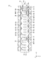
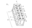
- FIG. 1 is an external perspective view of a battery module.
- FIG. 2 is a plan view of the battery module.
- FIG. 3 is an end view of the battery module.
- FIG. 4 is an external perspective view of a bus bar for electrodes.
- FIG. 5 is an external perspective view showing a state in which a plurality of bus bars are attached to the FPC board.
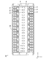
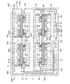
- FIG. 6 is a schematic plan view showing a configuration example of the FPC board.
- FIG. 7 is a schematic plan view for explaining the connection between the bus bar, the low potential side first circuit, and the high potential side first circuit.
- FIG. 8 is an enlarged plan view showing a part of the voltage / current bus bar and the FPC board.
- FIG. 9 is a block diagram showing electrical connections on the FPC board of FIG. FIG.
- FIG. 10 is a block diagram showing a configuration of the first circuit on the low potential side in FIG.
- FIG. 11 is a block diagram showing the configuration of the second circuit of FIG.
- FIG. 12 is a block diagram showing a configuration of a battery system using the battery module according to the first embodiment.
- FIG. 13 is a block diagram showing the connection between the battery module and the battery ECU.
- FIG. 14 is a plan view of a battery block according to the second embodiment.
- FIG. 15 is a plan view of a wiring member according to the second embodiment.
- FIG. 16 is a plan view of the battery module according to the second embodiment.
- FIG. 17 is a plan view of a battery block according to the third embodiment.
- FIG. 18 is a plan view of an FPC board according to the third embodiment.
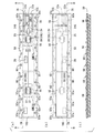
- FIG. 19 is a plan view and a sectional view of an FPC board according to the fourth embodiment.
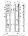
- FIG. 20 is a plan view and a cross-sectional view of an FPC board in the fifth embodiment.
- FIG. 21 is a plan view and a cross-sectional view of the FPC board according to the sixth embodiment.
- FIG. 22 is a plan view and a cross-sectional view of an FPC board according to the seventh embodiment.
- FIG. 23 is an exploded perspective view showing the configuration of the battery module according to the eighth embodiment.
- FIG. 24 is an exploded perspective view showing the configuration of the battery module according to the ninth embodiment.
- FIG. 25 is a perspective view of the lid member of FIG. 24 viewed obliquely from below.
- FIG. 26 is a perspective view of the lid member of FIG.
- FIG. 27 is an exploded perspective view showing the configuration of the battery module according to the tenth embodiment.
- FIG. 28 is a perspective view of the lid member of FIG. 27 as viewed obliquely from below.
- FIG. 29 is a perspective view of the lid member of FIG. 27 as viewed obliquely from above.
- FIG. 30 is a schematic plan view of a battery system including the battery module according to any one of the first to tenth embodiments.
- FIG. 31 is a block diagram illustrating a configuration of an electric vehicle including a battery system.
- FIG. 32 is a block diagram illustrating a configuration of a power supply device including a battery system.
- FIG. 33 is an external perspective view of a battery module including battery cells having a cylindrical shape.
- a battery module includes a battery block including a plurality of battery cells having electrode terminals, a voltage detection circuit for detecting a voltage between terminals of each battery cell, and a flexible printed circuit board.
- the battery block has one surface on which the electrode terminals of a plurality of battery cells are arranged, the flexible printed circuit board is provided on one surface side of the battery block, and each battery cell includes a voltage detection circuit and a flexible printed circuit.
- the flexible printed circuit board is mounted on the substrate, and the voltage detection line for electrically connecting the electrode terminal of each battery cell and the voltage detection circuit is integrally formed on an insulating substrate made of a flexible material. It is what has.
- a voltage detection circuit is mounted on a flexible printed circuit board provided on one side of a battery block in which electrode terminals of a plurality of battery cells are arranged.
- the electrode terminal of each battery cell and the voltage detection circuit are electrically connected by the voltage detection line of the flexible printed circuit board.
- the portion of the flexible printed circuit board to which the electrode terminal of each battery cell is connected has flexibility. Therefore, the insulating substrate of the flexible printed circuit board can be partially deformed. Therefore, even when there is a displacement between the electrode terminal of each battery cell and the connection part of the flexible printed circuit board due to an assembly error of the battery block or a dimensional error of a plurality of battery cells, the insulating substrate is partially deformed. By doing so, the displacement is absorbed. Thereby, the electrode terminal of each battery cell can be accurately and easily connected to the connection portion of the flexible printed circuit board. As a result, the working efficiency in the battery module assembly process is improved, and the reliability of the battery module is improved.
- the flexible printed circuit In addition, if a displacement occurs between the electrode terminal of each battery cell and the connection portion of the flexible printed circuit board after connecting the electrode terminal of each battery cell to the connection portion of the flexible printed circuit board, the flexible printed circuit The displacement is absorbed by the partial deformation of the insulating substrate of the substrate. Thereby, damage to the flexible printed circuit board is prevented. As a result, the reliability of the battery module is improved.
- the assembly accuracy of the battery block and the dimensional accuracy of multiple battery cells are eased. Thereby, the manufacturing yield of the battery module is improved. Furthermore, it is not necessary to separately provide a member or configuration for absorbing misalignment between the electrode terminals of the plurality of battery cells and the connection portion of the flexible printed circuit board. Therefore, the configuration and manufacturing process of the battery module are prevented from becoming complicated. As a result, the cost of the battery module can be reduced.
- the battery module may further include a reinforcing member that is provided on the flexible printed circuit board and has higher rigidity than the insulating substrate of the flexible printed circuit board. In this case, the durability of the flexible printed circuit board can be improved.
- a communication circuit connected to the voltage detection circuit is further mounted on the flexible printed circuit board, and an electronic component connected to at least one of the voltage detection circuit and the communication circuit is further mounted. And at least some of the plurality of portions may be arranged to reinforce a region where any of the voltage detection circuit, the communication circuit, and the electronic component of the flexible printed circuit board is mounted.
- the flexible printed circuit board includes a plurality of connection portions provided corresponding to a plurality of connection members that connect electrode terminals of adjacent battery cells to each other, and the plurality of connection portions are connected to the voltage detection circuit via voltage detection lines. It may be electrically connected.
- a plurality of connection portions are provided on the flexible printed circuit board corresponding to a plurality of connection members that connect electrode terminals of adjacent battery cells to each other.
- a battery system is a battery system connected to an external device, and is connected to open and close the battery module and an electrical connection between the external device and the battery module. And a control unit for controlling the operation of the switch.
- the battery module according to the above invention is provided. As a result, the reliability of the battery system can be improved and the cost can be reduced.
- An electric vehicle includes the battery system, a motor driven by electric power from a battery module of the battery system, and drive wheels that rotate by the rotational force of the motor. .
- a motor In this electric vehicle, a motor is driven by electric power from a plurality of battery cells.
- the drive wheel is rotated by the rotational force of the motor, so that the electric vehicle moves.
- the battery system according to the above invention is used for this electric vehicle, the reliability of the electric vehicle can be improved and the cost can be reduced.
- a moving body includes a battery source, a moving main body, a power source that converts electric power from a battery module of the battery system into power for moving the moving main body, And a drive unit that moves the moving main body by the power converted by the power source.
- the electric power from the battery system is converted into power by a power source, and the drive unit moves the moving main body by the power.
- the reliability of the moving body can be improved and the cost can be reduced.
- a power storage device includes the battery system and a system control unit that performs control related to charging or discharging of a battery module of the battery system.
- control related to charging or discharging of the battery module is performed by the system control unit. Thereby, deterioration, overdischarge, and overcharge of the battery module can be prevented.
- a power supply device is a power supply device that can be connected to the outside, and is controlled by the power storage device and a system control unit of the power storage device, and is a battery system of the power storage device. And a power conversion device that performs power conversion between the battery module and the outside.
- this power supply device power conversion is performed between the battery module and the outside by the power conversion device.
- Control related to charging or discharging of the battery module is performed by controlling the power conversion device by the system control unit of the power storage device. Thereby, deterioration, overdischarge, and overcharge of the battery module can be prevented.
- the battery system is used for this power supply device, the reliability of the power supply device can be improved and the cost can be reduced.
- the battery system using the battery module according to the present embodiment is mounted on an electric vehicle (for example, an electric automobile) using electric power as a drive source.
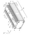
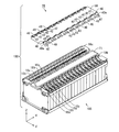
- FIG. 1 is an external perspective view of the battery module 100
- FIG. 2 is a plan view of the battery module 100
- FIG. 3 is an end view of the battery module 100.
- the X direction and the Y direction are directions parallel to the horizontal plane
- the Z direction is a direction orthogonal to the horizontal plane.
- the upward direction is the direction in which the arrow Z faces.
- a plurality of battery cells 10 having a flat, substantially rectangular parallelepiped shape are arranged in the X direction.
- Each battery cell 10 is a secondary battery such as a lithium ion battery or a nickel metal hydride battery.
- the plurality of battery cells 10 are integrally fixed by a pair of end face frames 92, a pair of upper end frames 93 and a pair of lower end frames 94.
- the plurality of battery cells 10, the pair of end face frames 92, the pair of upper end frames 93, and the pair of lower end frames 94 constitute a substantially rectangular parallelepiped battery block 10B.
- the battery block 10B has an upper surface parallel to the XY plane.
- the pair of end face frames 92 have a substantially plate shape and are arranged in parallel to the YZ plane.
- the pair of upper end frames 93 and the pair of lower end frames 94 are arranged so as to extend in the X direction.
- Connection portions for connecting the pair of upper end frames 93 and the pair of lower end frames 94 are formed at the four corners of the pair of end surface frames 92.
- the pair of upper end frames 93 are attached to the upper connection portions of the pair of end surface frames 92, and the lower connection of the pair of end surface frames 92 is performed.
- a pair of lower end frames 94 are attached to the part.
- the plurality of battery cells 10 are integrally fixed in a state of being arranged in the X direction.
- each battery cell 10 has a plus electrode 10a and a minus electrode 10b on the upper surface portion so as to be arranged along the Y direction.
- Each electrode 10a, 10b is provided to be inclined so as to protrude upward (see FIG. 3).
- the battery cells 10 adjacent to one end face frame 92 to the battery cells 10 adjacent to the other end face frame 92 are referred to as first to eighteenth battery cells 10.
- each battery cell 10 is arranged so that the positional relationship between the plus electrode 10 a and the minus electrode 10 b in the Y direction is opposite between adjacent battery cells 10. Further, one electrode 10a, 10b of the plurality of battery cells 10 is arranged in a line along the X direction, and the other electrode 10a, 10b of the plurality of battery cells 10 is arranged in a line along the X direction. Thereby, between two adjacent battery cells 10, the plus electrode 10a of one battery cell 10 and the minus electrode 10b of the other battery cell 10 are adjacent to each other, and the minus electrode 10b of one battery cell 10 and the other The positive electrode 10a of the battery cell 10 is adjacent. In this state, the bus bar 40 is attached to two adjacent electrodes. Thereby, the some battery cell 10 is connected in series.
- a common bus bar 40 is attached to the negative electrode 10b of the first battery cell 10 and the positive electrode 10a of the second battery cell 10.
- a common bus bar 40 is attached to the negative electrode 10b of the second battery cell 10 and the positive electrode 10a of the third battery cell 10.
- a common bus bar 40 is attached to the minus electrode 10b of each odd-numbered battery cell 10 and the plus electrode 10a of the even-numbered battery cell 10 adjacent thereto.
- a common bus bar 40 is attached to the minus electrode 10b of each even-numbered battery cell 10 and the plus electrode 10a of the odd-numbered battery cell 10 adjacent thereto.
- the bus bar 40a is attached to the plus electrode 10a of the first battery cell 10 and the minus electrode 10b of the 18th battery cell 10, respectively.
- the power of the battery module 100 is supplied to the outside by a power line 501 (see FIG. 12 described later) connected to the bus bar 40a.
- a belt-like flexible printed circuit board (hereinafter referred to as an FPC board) 50 extending in the X direction is provided on the upper surface of the battery block 10B.
- FPC board 50 On the FPC board 50, a first circuit 30 and the like for detecting a voltage between terminals of each battery cell 10 are mounted. Details will be described later.
- the FPC board 50 is commonly connected to the plurality of bus bars 40, 40a.
- bus bar 40 for connecting the plus electrode 10a and the minus electrode 10b of two adjacent battery cells 10 is called a two-electrode bus bar 40, and the plus electrode 10a or the minus electrode 10b of one battery cell 10 is called.
- the bus bar 40a for connecting the power line 501 and the power line 501 (see FIG. 12 described later) is referred to as a one-electrode bus bar 40a.
- FIG. 4A is an external perspective view of the bus bar 40 for two electrodes
- FIG. 4B is an external perspective view of the bus bar 40a for one electrode.
- the two-electrode bus bar 40 includes a base portion 41 having a substantially rectangular shape and a pair of attachment pieces 42 that bend and extend from one side of the base portion 41 to one surface thereof.
- a pair of electrode connection holes 43 are formed in the base portion 41.
- the bus bar 40a for one electrode includes a base portion 45 having a substantially square shape and a mounting piece 46 that is bent and extends from one side of the base portion 45 to one surface thereof.
- An electrode connection hole 47 is formed in the base portion 45.
- the bus bars 40, 40a have a configuration in which, for example, nickel plating is applied to the surface of tough pitch copper.
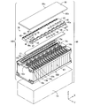
- FIG. 5 is an external perspective view showing a state in which a plurality of bus bars 40, 40a are attached to the FPC board 50.
- FIG. 5 mounting pieces 42 and 46 of a plurality of bus bars 40 and 40 a are attached to the FPC board 50 at predetermined intervals along the X direction.
- a member in which the FPC board 50 and the plurality of bus bars 40, 40a are integrally attached in this manner is referred to as a wiring member 70.
- the wiring member 70 is attached on the battery block 10B.
- the plus electrode 10a and the minus electrode 10b of the adjacent battery cells 10 are the electrodes of each bus bar 40. It is fitted in the connection hole 43. Further, the plus electrode 10a of the first battery cell 10 and the minus electrode 10b of the 18th battery cell 10 are fitted into the electrode connection holes 47 of the bus bar 40a, respectively. Male screws are formed on the plus electrode 10a and the minus electrode 10b. In a state where the bus bars 40 and 40a are fitted into the plus electrode 10a and the minus electrode 10b of the battery cell 10, a nut (not shown) is screwed into the male threads of the plus electrode 10a and the minus electrode 10b.
- the plurality of bus bars 40, 40a are attached to the plus electrode 10a or the minus electrode 10b of the plurality of battery cells 10 by nuts, but the present invention is not limited to this.
- the plurality of bus bars 40, 40a may be attached to the plus electrode 10a or the minus electrode 10b of the plurality of battery cells 10 by welding or the like.
- the wiring member 70 is attached to the battery block 10B, and the FPC board 50 of the wiring member 70 is held in a substantially horizontal posture on the upper surface of the battery block 10B.
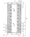
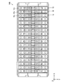
- FIG. 6 is a schematic plan view showing a configuration example of the FPC board 50.
- two first circuits 30, a second circuit 24, an insulating element 25, a discharge circuit 28, and a plurality of PTCs (Positive Temperature Coefficient) are provided on the main surface on the FPC board 50.
- the element 60, the power supply circuit 245, and the connectors 23a and 23b are mounted.
- a plurality of connection terminals 22 and a plurality of connection pads 52 a are formed on the FPC board 50.
- the FPC board 50 has a first mounting region 10G, a second mounting region 12G, and a strip-shaped insulating region 26 on the main surface.
- the second mounting region 12G is formed at a substantially central portion of one end portion of the FPC board 50.
- the insulating region 26 is formed so as to surround the second mounting region 12G.
- the first mounting region 10G is formed in the remaining part of the FPC board 50.
- the first mounting region 10G and the second mounting region 12G are separated from each other by the insulating region 26. Thereby, the first mounting region 10G and the second mounting region 12G are electrically insulated by the insulating region 26.
- the discharge circuit 28, the two first circuits 30, and the plurality of PTC elements 60 are mounted, and a plurality of connection pads 52a and a plurality of connection terminals 22 are formed.
- the plurality of connection pads 52 a are formed at equal intervals along both sides of the main surface of the FPC board 50.
- the plurality of connection pads 52a correspond to the plurality of bus bars 40, 40a in FIGS.
- the discharge circuit 28 and the plurality of connection pads 52a are electrically connected by a connection line (not shown).
- the two first circuits 30 and the plurality of connection terminals 22 are electrically connected by connection lines.
- a plurality of battery cells 10 (see FIG. 1) of the battery module 100 are connected to the first circuit 30 as power supplies for the two first circuits 30.
- the FPC board 50 may have a plurality of convex portions on both sides corresponding to the plus electrode 10a or the minus electrode 10b of the plurality of battery cells 10.
- the plurality of connection pads 52 a are formed on the convex portion of the FPC board 50.
- the plurality of bus bars 40, 40 a are connected to the connection pads 52 a on the convex portion of the FPC board 50.
- the ground pattern GND1L is formed around the mounting region of the low potential side first circuit 30L. Is formed.
- the ground pattern GND1L is held at the lowest potential of half of the plurality of battery cells 10 (9 in this example) on the low potential side (hereinafter referred to as a low potential battery cell group).
- the ground pattern GND1H is formed around the mounting region of the high potential side first circuit 30H. Is formed.
- the ground pattern GND1H is held at the lowest potential of half of the plurality of battery cells 10 on the high potential side (9 in this example) battery cells 10 (hereinafter referred to as a high potential battery cell group).
- the second circuit 24, the power supply circuit 245, and the connectors 23a and 23b are mounted.
- the second circuit 24 and the connector 23a are electrically connected by a connection line.
- the second circuit 24 is connected to the bus 103 of FIG. 13 described later via the connector 23a.
- the power supply circuit 245 and the connector 23b are electrically connected by a connection line.
- the power supply circuit 245 is connected to the switch circuit 107 of FIG. 13 to be described later via the connector 23b.
- the second circuit 24 and the power supply circuit 245 are electrically connected by a connection line.
- a ground pattern GND2 is formed in the second mounting region 12G except for the mounting region of the second circuit 24, the power supply circuit 245, and the connectors 23a and 23b.
- the ground pattern GND2 is held at a reference potential (ground potential) of the non-power battery 12 shown in FIG.
- the insulating element 25 is mounted so as to straddle the insulating region 26.
- the insulating element 25 transmits a signal between the first circuit 30L on the low potential side and the second circuit 24 while electrically insulating the ground pattern GND1L and the ground pattern GND2 from each other.
- a digital isolator or a photocoupler can be used as the insulating element 25.
- a digital isolator is used as the insulating element 25.
- FIG. 7 is a schematic plan view for explaining the connection between the bus bars 40, 40a, the low potential side first circuit 30L, and the high potential side first circuit 30H.
- the FPC board 50 has a configuration in which a conductor wire 52 and conductor wires 55H and 55L in FIG. 9 to be described later are mainly formed on an insulating layer 50a, and has flexibility and flexibility.
- a conductor wire 52 and conductor wires 55H and 55L in FIG. 9 to be described later are mainly formed on an insulating layer 50a, and has flexibility and flexibility.
- polyimide is used as the material of the insulating layer 50a constituting the FPC board 50
- copper is used as the material of the conductor lines 52, 55H, and 55L.
- the plurality of conductor lines 52 are provided so as to correspond to the plurality of connection pads 52a.
- Each PTC element 60 is arranged on the FPC board 50 so as to be close to each connection pad 52a.
- One end portion of each conductor wire 52 is connected to each connection pad 52a via the PTC element 60.
- the connection pieces 52 and 46 of the bus bars 40 and 40a are connected to the connection pads 52a, for example, by soldering or welding. Thereby, the plurality of bus bars 40, 40 a are fixed to the FPC board 50.
- the plurality of connection terminals 22 are provided so as to correspond to the plurality of conductor wires 52.
- Half of the connection terminals 22 and the low potential side first circuit 30L are electrically connected, and the remaining half of the connection terminals 22 and the high potential side first circuit 30H are electrically connected.
- the other end of each conductor wire 52 of the FPC board 50 is connected to the corresponding connection terminal 22 by, for example, soldering or welding.
- each bus bar 40, 40a is electrically connected to the low potential side first circuit 30L or the high potential side first circuit 30H via the PTC element 60. Thereby, the terminal voltage of each battery cell 10 is detected as will be described later.
- the PTC element 60 has a resistance temperature characteristic in which the resistance value rapidly increases when the temperature exceeds a certain value.
- the temperature of the PTC element 60 may increase due to a current flowing through the short circuit path. In that case, the resistance value of the PTC element 60 increases. This prevents a large current from flowing through the short circuit path including the PTC element 60.
- Each PTC element 60 is preferably arranged in a region between both ends of the corresponding bus bar 40, 40a.
- the area of the FPC board 50 between the adjacent bus bars 40, 40a is easily bent, but the area of the FPC board 50 between both ends of each bus bar 40, 40a is fixed to the bus bars 40, 40a. Therefore, it is kept relatively flat. Therefore, each PTC element 60 is disposed in the region of the FPC board 50 between both end portions of each bus bar 40, 40a, thereby ensuring sufficient connectivity between the PTC element 60 and the conductor wire 52. Moreover, the influence (for example, change of the resistance value of the PTC element 60) on each PTC element 60 by the bending of the FPC board 50 is suppressed.
- FIG. 8 is an enlarged plan view showing a part of the voltage / current bus bar 40 y and the FPC board 50. As shown in FIG. 8, the FPC board 50 further includes an amplifier circuit 410.
- solder patterns H1 and H2 are formed in parallel with each other at regular intervals.
- the solder pattern H1 is disposed between the two electrode connection holes 43 in the vicinity of one electrode connection hole 43
- the solder pattern H2 is disposed between the electrode connection holes 43 in the vicinity of the other electrode connection hole 43.
- the resistance formed between the solder patterns H1 and H2 in the voltage / current bus bar 40y is referred to as a current detection shunt resistance RS.
- the solder pattern H1 of the voltage / current bus bar 40y is connected to one input terminal of the amplifier circuit 410 via the conductor line 51 and the conductor line 52.
- the solder pattern H2 of the voltage / current bus bar 40y is connected to the other input terminal of the amplifier circuit 410 via the conductor line 51, the PTC element 60, and the conductor line 52.
- the output terminal of the amplifier circuit 410 is connected to one connection terminal 22. Thereby, the low potential side first circuit 30L or the high potential side first circuit 30H detects the voltage between the solder patterns H1 and H2 based on the output voltage of the amplifier circuit 410.
- the voltage between the solder patterns H1, H2 detected by the low potential side first circuit 30L or the high potential side first circuit 30H is applied to the second circuit 24 of FIG. As will be described later, the second circuit 24 calculates the value of the current flowing through the plurality of battery cells 10 based on the voltage between the solder patterns H1 and H2.
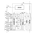
- FIG. 9 is a block diagram showing electrical connection on the FPC board 50 of FIG. In FIG. 9, illustration of the connection terminal 22 of FIGS. 6 and 7 is omitted.
- the low potential side first circuit 30L corresponds to the low potential side battery cell group 10L.
- the high potential side first circuit 30H corresponds to the high potential side battery cell group 10H.
- the low potential side first circuit 30L is electrically connected to the bus bars 40, 40a of the low potential side battery cell group 10L via the discharge circuit 28, the plurality of conductor wires 52 and the PTC element 60.
- the high potential side first circuit 30H is electrically connected to the bus bars 40, 40a of the high potential side battery cell group 10H via the discharge circuit 28, the plurality of conductor lines 52 and the PTC element 60.
- the low potential side first circuit 30L detects the terminal voltage of each of the plurality of battery cells 10 in the low potential side battery cell group 10L.
- the high potential side first circuit 30H detects the terminal voltage of each of the plurality of battery cells 10 in the high potential side battery cell group 10H.
- the low potential side first circuit 30L is electrically connected to the bus bar 40 of the battery cell 10 having the highest potential among the battery cells 10 of the low potential side battery cell group 10L through the conductor line 55L.
- the reference potential (ground potential) of the low potential side first circuit 30L is held at the lowest potential of the plurality of battery cells 10 in the low potential side battery cell group 10L. Thereby, electric power is supplied to the low potential side first circuit 30L from the plurality of battery cells 10 of the low potential side battery cell group 10L.
- the high potential side first circuit 30H is electrically connected to the bus bar 40a of the battery cell 10 having the highest potential among the battery cells 10 of the high potential side battery cell group 10H through the conductor line 55H.
- the reference potential (ground potential) of the high potential side first circuit 30H is held at the lowest potential of the plurality of battery cells 10 in the high potential side battery cell group 10H. Thereby, electric power is supplied to the high potential battery cell group 10H from the plurality of battery cells 10 in the high potential battery cell group 10H.
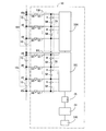
- the discharge circuit 28 corresponding to the first circuit 30L on the low potential side includes a plurality of sets (9 sets in this example) of series circuits each including the resistor R and the switching element SW. Between each two adjacent bus bars 40, a set of series circuits including a resistor R and a switching element SW is connected. A pair of series circuits including a resistor R and a switching element SW is also connected between each two adjacent bus bars 40 and 40a.
- the switching element SW is turned on and off by the second circuit 24 via the low potential side first circuit 30L. In the normal state, the switching element SW is turned off.
- the ON / OFF of the switching element SW is controlled by the second circuit 24 via the low-potential side first circuit 30L and the high-potential side first circuit 30H. Except for the discharge circuit 28 corresponding to the first circuit 30L on the low potential side.
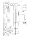
- FIG. 10 is a block diagram showing a configuration of the low potential side first circuit 30L of FIG.
- the low-potential-side first circuit 30L is composed of, for example, an ASIC (Application Specific Integrated Circuit).
- the low potential side first circuit 30L includes a detection unit 20, a control unit 31, a communication circuit 32, an equalization control circuit 33, and a power supply circuit 35.
- Reference potential hereinafter referred to as a component of the low potential side first circuit 30L
- (Ground potential) is held at the lowest potential of the plurality of battery cells 10 in the low potential side battery cell group 10L.
- the detection unit 20 includes a multiplexer 20a, an A / D (analog / digital) converter 20b, and a plurality of differential amplifiers 20c.
- Each differential amplifier 20c of the detection unit 20 has two input terminals and an output terminal.
- Each differential amplifier 20c differentially amplifies the voltage input to the two input terminals, and outputs the amplified voltage from the output terminal.
- each differential amplifier 20c Two input terminals of each differential amplifier 20c are connected to two adjacent bus bars 40 or two adjacent bus bars 40 of the plurality of battery cells 10 of the low potential side battery cell group 10L via the conductor line 52 and the PTC element 60.
- 40a is electrically connected.
- the voltage between the two adjacent bus bars 40 or the voltage between the two adjacent bus bars 40 and 40a is differentially amplified by each differential amplifier 20c.
- the output voltage of each differential amplifier 20c corresponds to the terminal voltage of each battery cell 10 in the low potential side battery cell group 10L.
- the voltages output from the plurality of differential amplifiers 20c are supplied to the multiplexer 20a.
- the multiplexer 20a sequentially outputs the terminal voltages supplied from the plurality of differential amplifiers 20c to the A / D converter 20b.
- the A / D converter 20b converts the terminal voltage output from the multiplexer 20a into a digital value.
- the control unit 31 is connected to the detection unit 20, the communication circuit 32, and the equalization control circuit 33.
- the communication circuit 32 has a communication function and is communicably connected to the second circuit 24 of FIG. 9 via the insulating element 25 of FIG. Further, the communication circuit 32 is connected to be communicable with the high potential side first circuit 30H of FIG.
- the control unit 31 acquires the digital value of the terminal voltage of each battery cell 10 of the low potential side battery cell group 10L from the A / D converter 20b of the detection unit 20. Further, as will be described later, the control unit 31 acquires the digital value of the terminal voltage of each battery cell 10 of the high potential side battery cell group 10H from the high potential side first circuit 30H via the communication circuit 32. Further, the control unit 31 isolates the digital value of the terminal voltage of each battery cell 10 of the low potential side battery cell group 10L and the digital value of the terminal voltage of each battery cell 10 of the high potential side battery cell group 10H from the communication circuit 32. It transmits to the 2nd circuit 24 via the element 25 (refer FIG. 9). The control unit 31 receives a command for equalization processing, which will be described later, transmitted from the second circuit 24 via the insulating element 25 and the communication circuit 32, and gives the command to the equalization control circuit 33.
- the equalization control circuit 33 performs the process of equalizing the state of charge of the battery cell 10 by turning on and off the switching element SW of the discharge circuit 28 based on a command from the second circuit 24.
- the power supply circuit 35 is electrically connected to the bus bar 40 having the highest potential of the low-potential side battery cell group 10L through the conductor line 55L.
- the power supply circuit 35 steps down or boosts the input voltage to a predetermined voltage (for example, 5 V) and outputs it.
- the components of the low potential side first circuit 30 ⁇ / b> L operate with the voltage output from the power supply circuit 35.
- Reference potential (hereinafter, referred to as a component of the high potential side first circuit 30H) of the detection unit 20, the control unit 31, the communication circuit 32, the equalization control circuit 33, and the power supply circuit 35 of the high potential side first circuit 30H. (Ground potential) is held at the lowest potential of the plurality of battery cells 10 in the high-potential side battery cell group 10H.
- the power supply circuit 35 is electrically connected to the bus bar 40a of the battery cell 10 having the highest potential among the plurality of battery cells 10 of the high potential side battery cell group 10H by a conductor line 55H instead of the conductor line 55L of FIG. .
- the communication circuit 32 of the high potential side first circuit 30H is communicably connected to the communication circuit 32 (see FIG. 10) of the low potential side first circuit 30L.
- the control unit 31 of the high potential side first circuit 30H passes through the communication circuit 32 of the high potential side first circuit 30H, the communication circuit 32 of the low potential side first circuit 30L, and the insulating element 25 (see FIG. 9).
- the digital value of the terminal voltage of each battery cell 10 of the high potential side battery cell group 10H can be transmitted to the second circuit 24.
- FIG. 11 is a block diagram showing the configuration of the second circuit 24 of FIG.
- the second circuit 24 includes a processing unit 241, a storage unit 242, and a communication interface 244.
- the processing unit 241, the storage unit 242, and the communication interface 244 operate with a voltage (for example, 5V) output from the power supply circuit 245 of FIG.
- the processing unit 241 includes a CPU (Central Processing Unit), for example, and is connected to the storage unit 242.
- the processing unit 241 is connected to a plurality of thermistors 11 shown in FIG. Thereby, the processing unit 241 acquires the temperature of the battery module 100.
- the processing unit 241 functions to process the terminal voltage, current, and other information transmitted from the detection unit 20 (see FIGS. 9 and 10) of the low potential side first circuit 30L and the high potential side first circuit 30H.
- the processing unit 241 calculates the charge amount of each battery cell 10, the current flowing through the plurality of battery cells 10, and the like.
- the terminal voltage of the battery cell, the current flowing through the plurality of battery cells 10 and the temperature of the battery module 100 are referred to as cell information. Details of the calculation of the current flowing through the plurality of battery cells 10 will be described later.
- the storage unit 242 includes a non-volatile memory such as an EEPROM (electrically erasable and programmable read-only memory).
- EEPROM electrically erasable and programmable read-only memory
- the value of the shunt resistance RS between the solder patterns H1 and H2 in the voltage / current bus bar 40y of FIG. 8 is stored in advance.
- the processing unit 241 includes a communication circuit 246 having a communication function.
- the processing unit 241 is communicably connected to the communication circuit 32 (see FIG. 10) of the low potential side first circuit 30L via the insulating element 25 (see FIG. 9).
- the processing unit 241 of the second circuit 24 in FIG. 11 includes a shunt resistor in which the voltage between the solder patterns H1 and H2 given from the low potential side first circuit 30L or the high potential side first circuit 30H is stored in the storage unit 242. By dividing by the value of RS, the value of the current flowing through the voltage / current bus bar 40y is calculated.
- the processing unit 241 gives various commands for equalization processing to the control unit 31 (see FIGS. 9 and 10) of the low potential side first circuit 30L and the high potential side first circuit 30H.
- a communication interface 244 is connected to the processing unit 241.
- the communication interface 244 is an RS-485 standard serial communication interface, for example.
- the communication circuit 246 performs RS-485 standard serial communication with the battery ECU 101 of FIG. 12 described later, but is not limited thereto.
- the communication circuit 246 may perform serial communication of other standards with the battery ECU 101, and may perform CAN (Controller Area Network) communication with the battery ECU 101.
- the second circuit 24 may be a microcomputer having functions of the processing unit 241, the storage unit 242, and the communication interface 244.
- the cell information is transmitted to the battery ECU 101 by the communication circuit 246 of the second circuit 24, or various information and commands are received from the battery ECU 101.
- the second circuit 24 operates by electric power supplied from the non-power battery 12 shown in FIG. Thereby, even when the voltage of the battery cell 10 of any battery module 100 of the battery system 500 is lowered, the battery module 100 can communicate with the battery ECU 101.
- the second circuit 24 of each battery module 100 calculates the charge amount of each battery cell 10 based on the cell information.
- the second circuit 24 performs charge / discharge control of each battery cell 10 based on the terminal voltage value of each battery cell 10 transmitted from the low potential side first circuit 30L and the high potential side first circuit 30H.
- the second circuit 24 of each battery module 100 detects an abnormality of each battery module 100 based on the cell information.
- the abnormality of the battery module 100 is, for example, overdischarge, overcharge, or temperature abnormality of the battery cell 10.
- each second circuit 24 provides the battery ECU 101 with a calculation result of the charge amount of each battery cell 10 and detection results such as overdischarge, overcharge, and temperature abnormality of the battery cell 10.
- the second circuit 24 of each battery module 100 calculates the amount of charge of each battery cell 10 described above, detects battery cell 10 overdischarge, overcharge, temperature abnormality, and the like and performs equalization processing.
- the battery ECU 101 may perform various commands for calculation of the charge amount of each battery cell 10, detection of overdischarge, overcharge and temperature abnormality of the battery cell 10, and equalization processing.
- the low potential side first circuit 30L (see FIG. 9) and the second circuit 24 are communicably connected while being electrically insulated by the insulating element 25 (see FIG. 9). Further, the high potential side first circuit 30H (see FIG. 9) and the second circuit 24 are connected to each other via the low potential side first circuit 30L while being electrically insulated.
- a plurality of battery cells 10 can be used as the power source for the low potential side first circuit 30L and the high potential side first circuit 30H, and the non-power battery 12 (see FIG. 12 described later) as the power source for the second circuit 24. ) Can be used.
- the second circuit 24 can be stably operated independently from the low potential side first circuit 30L and the high potential side first circuit 30H.
- FIG. 12 is a block diagram showing a configuration of a battery system using the battery module according to the present embodiment.
- the battery system 500 includes a plurality of battery modules 100 (four in this example), a battery ECU 101 and a contactor 102.
- the plurality of battery modules 100 are connected to the battery ECU 101 via the bus 103.
- the battery ECU 101 of the battery system 500 is connected to the main control unit 300 of the electric vehicle via the bus 104.
- the plurality of battery modules 100 of the battery system 500 are connected to each other through the power line 501.
- Each battery module 100 includes a plurality of (four in this example) thermistors 11 together with the battery cells 10 and the FPC board 50.
- all the battery cells 10 of the plurality of battery modules 100 are connected in series.
- the power supply line 501 connected to the highest potential positive electrode 10a (see FIG. 1) and the power supply line 501 connected to the lowest potential negative electrode 10b (see FIG. 1) of the plurality of battery modules 100 are connected to the contactor 102.
- a load such as a motor of an electric vehicle.
- the battery ECU 101 detects an abnormality of the battery module 100 from the second circuit 24 of FIG. 11, the battery ECU 101 turns off the contactor 102.
- MPU 106 (see FIG. 13 described later) of battery ECU 101 controls on / off of contactor 102, but the present invention is not limited to this.
- the second circuit 24 of the battery module 100 may control on and off of the contactor 102.
- the battery ECU 101 gives the main controller 300 the amount of charge of each battery module 100 (the amount of charge of the battery cell 10).
- the main control unit 300 controls the power of the electric vehicle (for example, the rotational speed of the motor) based on the amount of charge.
- the main control unit 300 controls each power generation device (not shown) connected to the power line 501 to charge each battery module 100.
- the power generation device is a motor connected to the power supply line 501 described above, for example.
- the motor converts the electric power supplied from the battery system 500 during acceleration of the electric vehicle into motive power for driving drive wheels (not shown).
- the motor generates regenerative power when the electric vehicle is decelerated. Each battery module 100 is charged by this regenerative power.
- FIG. 13 is a block diagram showing the connection between the battery module and the battery ECU.
- the battery ECU 101 has a printed circuit board 105.
- a microprocessor (MPU) 106, a switch circuit 107, and a power supply circuit 108 are mounted on the printed circuit board 105.
- Other circuits such as a contactor control circuit for turning on and off the contactor 102 of FIG. 12 are also mounted on the printed circuit board 105.
- the power supply circuit 108 steps down the voltage supplied from the non-power battery 12 via the switch circuit 107 and supplies it to the MPU 106. That is, the non-power battery 12 is used as a power source for the MPU 106.
- the non-power battery 12 is a lead storage battery.
- the switch circuit 107 of the printed circuit board 105 is connected to the power supply circuit 245 of the FPC board 50 through the connector 23b of FIG. On / off of the switch circuit 107 is controlled by the MPU 106.
- the switch circuit 107 When the switch circuit 107 is on, power from the non-power battery 12 is supplied to the second circuit 24 via the switch circuit 107 and the power supply circuit 245 of the FPC board 50. Thereby, the second circuit 24 operates. That is, the non-power battery 12 is used as a power source for the second circuit 24.
- the second circuit 24 is connected to the bus 103.
- the MPU 106 is connected to the bus 103. Thereby, MPU106 of battery ECU101 and the 2nd circuit 24 of each battery module 100 are connected so that communication is possible.
- the MPU 106 transmits various commands for equalization processing to the low potential side first circuit 30L and the high potential side first circuit 30H via the bus 103, the second circuit 24, and the insulating element 25.
- the low potential side first circuit 30L and the high potential side first circuit 30H have a function of calculating SOH (StateSOf Health: life of the battery cell 10) and SOC (State Of Charge: state of charge). Also good.
- the second circuit 24 acquires the information of the battery cell 10 such as SOH and SOC from the low potential side first circuit 30L or the high potential side first circuit 30H to the MPU 106 via the bus 103, and the acquired information It transmits to MPU106. Further, the second circuit 24 transmits failure determination information of the FPC board 50 to the MPU 106.
- the MPU 106 may be provided in the main control unit 300 in FIG. Further, the functions of the MPU 106 may be provided in a distributed manner in the second circuit 24 and the main control unit 300. Further, the MPU 106 is communicably connected to the main control unit 300 (see FIG. 12) of the electric vehicle via the bus 104 (see FIG. 12).
- the low potential side first circuit 30L and the high potential side first circuit 30H are mounted on the FPC board 50 provided on the upper surface of the battery block 10B.
- Connection pads 52a are formed along both sides of the FPC board 50, and the bus bars 40, 40a are connected to the connection pads 52a.
- the bus bars 40, 40a and the low potential side first circuit 30L or the high potential side first circuit 30H are electrically connected by the conductor wire 52 of the FPC board 50.
- the FPC board 50 has flexibility. Therefore, there is a displacement between the plus electrode 10a or minus electrode 10b of each battery cell 10 and the bus bars 40, 40a connected to the FPC board 50 due to an assembly error of the battery block 10B or a dimensional error of the plurality of battery cells 10. Even in this case, the FPC board 50 is partially deformed, so that the misalignment is absorbed. Thereby, the bus bars 40 and 40a can be connected to the plus electrode 10a or the minus electrode 10b of each battery cell 10 accurately and easily. As a result, the work efficiency in the assembly process of the battery module 100 is improved, and the reliability of the battery module 100 is improved.
- the bus bars 40 and 40a are connected to the battery cells 10 plus electrode 10a or the minus electrode 10b and a displacement occurs between the plus electrodes 10a or minus electrodes 10b of the battery cells 10 and the bus bars 40 and 40a.
- the position shift is absorbed by the FPC board 50 being partially deformed. Thereby, the FPC board 50 is prevented from being damaged. As a result, the reliability of the battery module 100 is improved.
- the assembly accuracy of the battery block 10B and the dimensional accuracy of the plurality of battery cells 10 are alleviated. Thereby, the manufacturing yield of the battery module 100 is improved. Furthermore, it is not necessary to separately provide a member or a structure for absorbing displacement between the plus electrode 10a or the minus electrode 10b of the plurality of battery cells 10 and the bus bars 40, 40a. Therefore, the configuration of the battery module 100 is prevented from becoming complicated. As a result, the cost of the battery module 100 can be reduced.
- Second Embodiment A battery module according to a second embodiment will be described while referring to differences from the battery module 100 according to the first embodiment.
- FIG. 14 is a plan view of the battery block 10B according to the second embodiment.
- the battery cell 10 in the present embodiment has a gas vent valve 10v at the center of the upper surface portion.
- the gas inside the battery cell 10 is discharged from the gas vent valve 10v of the battery cell 10. Thereby, the excessive raise of the pressure inside the battery cell 10 is prevented.
- FIG. 15 is a plan view of the wiring member 70 according to the second embodiment. As shown in FIG. 15, in the FPC board 50 of the wiring member 70 in the present embodiment, the plurality of battery cells of FIG. 14 are equally spaced so that the plurality of holes H are arranged in the center along the length direction. 10 degassing valves 10v are formed so as to correspond respectively.
- the second mounting region 12G is formed at a substantially central portion of one end of the FPC board 50.
- the insulating region 26 is formed so as to surround the second mounting region 12G and not overlap with the plurality of holes H.
- the first mounting region 10G is formed in the remaining part of the FPC board 50.
- the discharge circuit 28, the low potential side first circuit 30L, the high potential side first circuit 30H, and the plurality of PTC elements 60 are mounted so as not to overlap the plurality of holes H.
- a plurality of connection pads 52a and a plurality of connection terminals 22 are formed.
- the low potential side first circuit 30L is excluded except for the mounting region of the low potential side first circuit 30L and the formation region of the connection terminal 22 so as not to overlap with the plurality of holes H.
- a ground pattern GND1L is formed around the mounting region.
- the high potential side first circuit 30H is excluded except for the mounting region of the high potential side first circuit 30H and the formation region of the connection terminal 22 so as not to overlap with the plurality of holes H.
- a ground pattern GND1H is formed around the mounting region.
- the second circuit 24, the power supply circuit 245, and the connectors 23a and 23b are mounted in the second mounting region 12G so as not to overlap with the plurality of holes H. Further, in the second mounting region 12G, the second circuit 24, the power supply circuit 245, and the second circuit 24, except for the mounting region of the connectors 23a and 23b, so as not to overlap with the plurality of holes H.
- a ground pattern GND2 is formed around the connectors 23a and 23b.
- the insulating element 25 is mounted so as not to overlap the plurality of holes H and straddle the insulating region 26.
- FIG. 16 is a plan view of the battery module 100 according to the second embodiment.
- the plurality of holes H of the FPC board 50 are respectively positioned above the gas vent valves 10 v of the plurality of battery cells 10.
- the pressure inside the battery cell 10 rises to a predetermined value
- the gas inside the battery cell 10 is not obstructed by the FPC board 50 of the wiring member 70, and the plurality of holes H are opened from the gas vent valve 10 v. It is possible to discharge to the outside through.
- FIG. 17 is a plan view of the battery block 10B according to the third embodiment. As shown in FIG. 17, in the present embodiment, the plurality of bus bars 40, 40a are connected in advance to the plus electrode 10a or the minus electrode 10b of the plurality of battery cells 10 by soldering or welding in advance.
- FIG. 18 is a plan view of the FPC board 50 according to the third embodiment.
- a plurality of welding members 52b are respectively attached in advance to the plurality of connection pads 52a of the FPC board 50 in the present embodiment.
- the FPC board 50 is disposed on the upper surface of the battery block 10B so that the welding members 52b attached to the plurality of connection pads 52a overlap the plurality of bus bars 40, 40a, respectively. Thereafter, the plurality of welding members 52b are welded to the plurality of bus bars 40, 40a, whereby the connection pads 52a of the FPC board 50 are connected to the plurality of bus bars 40, 40a, respectively.
- connection pad 52a can be easily positioned on the bus bars 40, 40a connected to the plus electrode 10a or the minus electrode 10b of the plurality of battery cells 10. it can. Thereby, the battery module 100 can be easily assembled.
- the plurality of bus bars 40, 40a are attached to the plus electrode 10a or the minus electrode 10b of the plurality of battery cells 10 by welding, but the present invention is not limited to this.
- the plurality of bus bars 40, 40a may be attached to the plus electrode 10a or the minus electrode 10b of the plurality of battery cells 10 by nuts.
- FIG. 19 is a plan view and a cross-sectional view of the FPC board 50 according to the fourth embodiment.
- 19 (a) is a plan view of the main surface of the FPC board 50
- FIG. 19 (b) is a plan view of the back surface of the FPC board 50
- FIG. 19 (c) is a plan view of FIGS. 19 (a) and 19 (b). 2 is a cross-sectional view of the FPC board 50 of FIG.
- the configuration of the main surface of the FPC board 50 in the present embodiment is the same as the configuration of the main surface of the FPC board 50 in FIG.
- the FPC board 50 in this embodiment has a reinforcing plate 56 on the back surface except for a constant width region at the peripheral edge to which the plurality of bus bars 40, 40a are connected. Are joined.
- the reinforcing plate 56 is bonded to the FPC board 50 with an adhesive or the like.
- the reinforcing plate 56 is made of, for example, glass epoxy resin and has higher rigidity than the FPC board 50. Thereby, the durability of the FPC board 50 can be improved while ensuring the flexibility of the peripheral region to which the plurality of bus bars 40, 40a are connected.
- the reinforcing plate 56 is preferably formed of a material having a thermal expansion coefficient comparable to that of the insulating layer 50a (see FIG. 7) constituting the FPC board 50. As a result, even if the dimension of the reinforcing plate 56 changes due to a temperature change, the dimension of the FPC board 50 changes in the same manner, so that the reinforcing board 56 is prevented from peeling off from the FPC board 50. Furthermore, the reinforcing plate 56 is preferably formed of a non-conductive material. Thereby, even when the reinforcement board 56 contacts the battery block 10B, it is prevented that the some battery cell 10 short-circuits.
- the reinforcing plate 56 is formed of a glass epoxy resin, but other materials such as a polyetheretherketone (PEEK) resin, a polyphenylsulfone (PPSU) resin, or a polyethersulfone (PES) resin are used. It may be formed of a material.
- PEEK polyetheretherketone
- PPSU polyphenylsulfone
- PES polyethersulfone
- FIG. 20 is a plan view and a cross-sectional view of the FPC board 50 according to the fifth embodiment.
- 20 (a) is a plan view of the main surface of the FPC board 50
- FIG. 20 (b) is a plan view of the back surface of the FPC board 50
- the configuration of the main surface of the FPC board 50 in the present embodiment is the same as the configuration of the main surface of the FPC board 50 in FIG.
- the FPC board 50 in the present embodiment includes a plurality of (books) on the back surface except for a constant width region at the peripheral edge to which the plurality of bus bars 40, 40a are connected.
- three reinforcing plates 56 are joined. Each portion of the plurality of reinforcing plates 56 is formed on the FPC board 50 on which the low potential side first circuit 30L, the high potential side first circuit 30H, the second circuit 24, the insulating element 25, the discharge circuit 28, and the power supply circuit 245 are mounted. Arranged to reinforce the area.
- the low potential side first circuit 30L, the high potential side first circuit 30H, the second circuit 24 of the FPC board 50 are secured while ensuring the flexibility of the peripheral region to which the plurality of bus bars 40, 40a are connected.
- the durability of the region where the insulating element 25, the discharge circuit 28, and the power supply circuit 245 are mounted can be improved.
- the FPC board 50 can be bent in the region between the reinforcing plates 56. Thereby, the degree of freedom of deformation of the FPC board 50 is improved. As a result, the displacement between the positive electrode 10a or the negative electrode 10b of each battery cell 10 and the bus bars 40, 40a connected to the FPC board 50 is sufficiently absorbed.
- FIG. 21 is a plan view and a cross-sectional view of the FPC board 50 in the sixth embodiment.
- 21 (a) is a plan view of the main surface of the FPC board 50
- FIG. 21 (b) is a plan view of the back surface of the FPC board 50
- the configuration of the main surface of the FPC board 50 in the present embodiment is the same as the configuration of the main surface of the FPC board 50 in FIG.
- the FPC board 50 in the present embodiment has a reinforcing plate 56 on the back surface except for a constant width region at the peripheral edge to which the plurality of bus bars 40, 40a are connected. Are joined.
- the reinforcing plate 56 in the present embodiment has a rectangular frame-like structure such as “B”.
- the durability of the FPC board 50 can be improved while ensuring the flexibility of the peripheral area to which the plurality of bus bars 40, 40a are connected. Moreover, since the reinforcing plate 56 does not exist in the center part of the FPC board 50, the battery module 100 according to the present embodiment is reduced in weight compared to the battery module 100 according to the fourth embodiment.
- FIG. 22 is a plan view and a cross-sectional view of the FPC board 50 according to the seventh embodiment.
- 22 (a) is a plan view of the main surface of the FPC board 50
- FIG. 22 (b) is a plan view of the back surface of the FPC board 50
- the configuration of the main surface of the FPC board 50 in the present embodiment is the same as the configuration of the main surface of the FPC board 50 in FIG.
- the FPC board 50 in the present embodiment includes a plurality of (books) on the back surface except for a constant width region at the peripheral edge to which the plurality of bus bars 40, 40a are connected.
- three reinforcing plates 56 are joined.
- the reinforcing plate 56 in the present embodiment has a rectangular frame-like structure such as “B”.
- Each portion of the plurality of reinforcing plates 56 is formed on the FPC board 50 on which the low potential side first circuit 30L, the high potential side first circuit 30H, the second circuit 24, the insulating element 25, the discharge circuit 28, and the power supply circuit 245 are mounted. Arranged to reinforce the area.
- the low potential side first circuit 30L, the high potential side first circuit 30H, the second circuit 24 of the FPC board 50 are secured while ensuring the flexibility of the peripheral region to which the plurality of bus bars 40, 40a are connected.
- the durability of the region where the insulating element 25, the discharge circuit 28, and the power supply circuit 245 are mounted can be improved.
- the reinforcing plate 56 does not exist in the center part of the FPC board 50, the battery module 100 according to the present embodiment is lighter than the battery module 100 according to the fifth embodiment.
- the FPC board 50 can be bent in the region between the reinforcing plates 56. Thereby, the degree of freedom of deformation of the FPC board 50 is improved. As a result, the displacement between the positive electrode 10a or the negative electrode 10b of each battery cell 10 and the bus bars 40, 40a connected to the FPC board 50 is sufficiently absorbed.
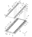
- FIG. 23 is an exploded perspective view showing the configuration of the battery module 100 according to the eighth embodiment.
- the battery module 100 further includes a gas duct 71.
- the gas duct 71 is provided on the upper surface of the battery block 10B so as to cover the gas vent valves 10v (see FIG. 14) of the plurality of battery cells 10.
- the wiring member 70 is mounted on the battery block 10B as in the first embodiment.
- the gas discharged from the gas vent valve 10v of the battery cell 10 is released to the outside through the gas duct 71 without being obstructed by the wiring member 70. Therefore, the gas can be discharged from the gas vent valve 10v to the outside without providing a plurality of holes H (see FIG. 15) in the FPC board 50 of the wiring member 70.
- FIG. 10 A battery module according to the ninth embodiment will be described while referring to differences from the battery module 100 according to the eighth embodiment.
- battery module 100 is arranged in a casing (housing) CA having an open top.
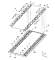
- FIG. 24 is an exploded perspective view showing the configuration of the battery module 100 according to the ninth embodiment.
- the battery module 100 further includes a lid member 80.
- the lid member 80 is made of an insulating material such as resin and has a rectangular plate shape.
- a gas duct 71, a wiring member 70, and a lid member 80 are sequentially arranged on the upper surface of the battery block 10B.
- the wiring member 70 is attached to the lower surface of the lid member 80, and the gas duct 71 is attached to the lower surface of the wiring member 70.
- Battery block 10B is housed in casing CA, and lid member 80 is fitted to casing CA so as to close the opening of casing CA. Thereby, the battery box BB that houses the battery module 100 is formed.
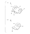
- FIG. 25 is a perspective view of the lid member 80 of FIG. 24 as viewed obliquely from below.
- FIG. 26 is a perspective view of the lid member 80 of FIG. 24 as viewed obliquely from above.
- the side 80a of the lid member 80 is along the side E1 (see FIG. 24) on one side of the battery block 10B (see FIG. 24), and the side 80b of the lid 80 is the side E2 on the other side of the battery block 10B (see FIG. 24). See).
- the surface of the lid member 80 facing the battery block 10B is called a back surface
- the surface of the lid member 80 on the opposite side is called a front surface. In this example, the surface of the lid member 80 is directed upward.
- a plurality of recesses 81 and 82 are provided on the back surface of the lid member 80 so as to extend along the side 80 a and the side 80 b of the lid member 80.
- nine recesses 81 are provided along the side 80 a of the lid member 80.
- One recess 82, eight recesses 81, and another one recess 82 are provided along the side 80 b of the lid member 80.
- the concave portions 81 and 82 have a substantially rectangular shape, and the length of the concave portion 81 in the X direction is larger than the length of the concave portion 82 in the X direction.
- the shape and length of the recess 81 are substantially equal to the shape and length of the bus bar 40, and the shape and length of the recess 82 are substantially equal to the shape and length of the bus bar 40a.
- a plurality of openings 83 are formed so as to penetrate from the bottom surfaces of the plurality of recesses 81 and 82 to the surface of the lid member 80 (see FIG. 26). Two openings 83 (see FIG. 26) are formed in each recess 81, and one opening 83 (see FIG. 26) is formed in each recess 82.
- the recess 81 and the opening 83 provided along the side 80a of the lid member 80 are referred to as the recess 81 on the side 80a and the opening 83 on the side 80a, respectively, and along the side 80b of the lid 80.
- the recesses 81 and 82 and the opening 83 thus provided are referred to as the recesses 81 and 82 on the side 80b side and the opening 83 on the side 80b side, respectively.
- the bus bar 40 of the wiring member 70 is fitted into the recess 81 of the lid member 80, and the bus bar 40 a of the wiring member 70 is fitted into the recess 82.
- the electrode connection hole 43 of the bus bar 40 is exposed to the surface side of the lid member 80 in the opening 83.
- the electrode connection hole 47 of the bus bar 40 a is exposed to the surface side of the lid member 80 in the opening 83 in a state where the bus bar 40 a is fitted in the recess 82.
- the FPC fitting portion 84 is formed so as to extend in the X direction between the plurality of recesses 81 on the side 80a side and the plurality of recesses 81, 82 on the side 80b side.
- the FPC board 50 of the wiring member 70 is fitted into the FPC fitting portion 84.
- a plurality of pairs of connection grooves 85 are formed so as to extend from the plurality of recesses 81 to the FPC fitting portion 84, respectively.
- a plurality of connection grooves 86 are formed so as to extend from the plurality of recesses 82 on the side 80b side to the FPC fitting portion 84, respectively.
- a pair of attachment pieces 42 of the plurality of bus bars 40 are respectively disposed in the plurality of pairs of connection grooves 85. In the plurality of connection grooves 86, the attachment pieces 46 of the plurality of bus bars 40a are respectively arranged.
- the gas duct 71 (see FIG. 24) is joined to the FPC board 50 with an adhesive or the like. In this way, the gas duct 71 and the wiring member 70 are attached to the lid member 80. In this state, the lid member 80 is attached to the upper surface of the battery block 10B.
- the plus electrodes 10a (see FIG. 24) and the minus electrodes 10b (see FIG. 24) of the plurality of battery cells 10 are fitted into the electrode connection holes 43 of the plurality of bus bars 40.
- the positive electrodes 10a or the negative electrodes 10b of the plurality of battery cells 10 are inserted into the electrode connection holes 47 of the plurality of bus bars 40a.
- the gas duct 71 is disposed on the upper surface of the battery block 10B so as to cover the gas vent valves 10v of the plurality of battery cells 10.
- a nut (not shown) is screwed to the male threads of the plus electrode 10a and the minus electrode 10b. Thereby, adjacent battery cells 10 are electrically connected via the bus bar 40. As a result, the plurality of battery cells 10 are connected in series.
- the gas duct 71 and the wiring member 70 are integrally provided on the lid member 80. Therefore, the battery module 100 can be easily assembled by attaching the lid member 80 to the battery block 10B.
- the strength of the battery module 100 is improved. Further, since the battery block 10B of the battery module 100 is fixed to the casing CA of the battery box BB and the lid member 80 is fitted to the casing CA, the battery block 10B and the lid member 80 can be reliably fixed. .
- the opening of the casing CA is closed by the lid member 80. Therefore, the inside of the battery box BB may be molded with resin. In this case, condensation of the battery cell 10 can be prevented. Further, the resin molded in the battery box BB can affect the heat conduction characteristics of the battery module 100. For example, by molding the inside of the battery box BB with a resin having a higher thermal conductivity than air, the heat in the battery box BB can be released to the outside. On the other hand, by molding the inside of the battery box BB with a resin having a thermal conductivity lower than that of air, the inflow of heat from the outside into the battery box BB can be blocked.
- the inside of the battery box BB can be exhausted by providing a hole in at least one of the casing CA and the lid member 80.
- the gas duct 71 may not be provided in the battery module 100.
- FIG. 27 is an exploded perspective view showing the configuration of the battery module 100 according to the tenth embodiment. As shown in FIG. 27, the gas duct 71, the lid member 80, and the wiring member 70 are sequentially arranged on the upper surface of the battery block 10B. The wiring member 70 is attached to the upper surface of the lid member 80, and the gas duct 71 is attached to the lower surface of the lid member 80.
- FIG. 28 is a perspective view of the lid member 80 of FIG. 27 as viewed obliquely from below.
- FIG. 29 is a perspective view of the lid member 80 of FIG. 27 as viewed obliquely from above.
- the one side and the other side of the lid member 80 along the X direction are referred to as a side 80c and a side 80d, respectively.
- the side 80c of the lid member 80 is along the side E1 (see FIG. 27) on one side of the battery block 10B (see FIG. 27), and the side 80d of the lid 80 is the side E2 on the other side of the battery block 10B (see FIG. 27). See).
- a plurality of recesses 81 and 82 are provided along the side 80c and the side 80d of the lid member 80.
- nine concave portions 81 are provided along the side 80 c of the lid member 80.
- One recess 82, eight recesses 81, and another one recess 82 are provided along the side 80 d of the lid member 80.
- a plurality of openings 83 are formed so as to penetrate from the bottom surfaces of the plurality of recesses 81 and 82 to the back surface of the lid member 80 (see FIG. 28). Two openings 83 (see FIG. 28) are formed in each recess 81, and one opening 83 (see FIG. 28) is formed in each recess 82.
- the bus bar 40 of the wiring member 70 is fitted into the recess 81 of the lid member 80, and the bus bar 40 a of the wiring member 70 is fitted into the recess 82.
- the electrode connection hole 43 of the bus bar 40 is exposed to the back side of the lid member 80 in the opening 83.
- the electrode connection hole 47 of the bus bar 40 a is exposed to the back surface side of the lid member 80 in the opening 83 in a state where the bus bar 40 a is fitted in the recess 82.
- the FPC fitting portion 84 is formed so as to extend in the X direction between the plurality of recesses 81 on the side 80c side and the plurality of recesses 81, 82 on the side 80d side.
- the FPC board 50 of the wiring member 70 is fitted into the FPC fitting portion 84.
- a plurality of pairs of connection grooves 85 are formed so as to extend from the plurality of recesses 81 to the FPC fitting portion 84, respectively.
- a plurality of connection grooves 86 are formed so as to extend from the plurality of recesses 82 on the side 80d side to the FPC fitting portion 84, respectively.
- a pair of attachment pieces 42 of the plurality of bus bars 40 are respectively disposed in the plurality of pairs of connection grooves 85. In the plurality of connection grooves 86, the attachment pieces 46 of the plurality of bus bars 40a are respectively arranged.
- a duct fitting portion 87 is formed on the back surface of the lid member 80 so as to extend in the X direction between the plurality of openings 83 on the side 80c side and the plurality of openings 83 on the side 80d side. It is formed. A gas duct 71 is fitted into the duct fitting portion 87.
- the gas duct 71 and the wiring member 70 are attached to the lid member 80.
- the lid member 80 is attached to the upper surface of the battery block 10B.
- the positive electrodes 10a (see FIG. 27) and the negative electrodes 10b (see FIG. 27) of the plurality of battery cells 10 are fitted into the electrode connection holes 43 of the plurality of bus bars 40.
- the positive electrodes 10a or the negative electrodes 10b of the plurality of battery cells 10 are inserted into the electrode connection holes 47 of the plurality of bus bars 40a.
- the gas duct 71 is disposed on the upper surface of the battery block 10B so as to cover the gas vent valves 10v of the plurality of battery cells 10.
- a nut (not shown) is screwed into the male threads of the plus electrode 10a and the minus electrode 10b. Thereby, adjacent battery cells 10 are electrically connected via the bus bar 40. As a result, the plurality of battery cells 10 are connected in series.
- the gas duct 71 and the wiring member 70 are integrally provided on the lid member 80. Therefore, the battery module 100 can be easily assembled by attaching the lid member 80 to the battery block 10B.
- the FPC board 50 is provided on the upper surface of the battery block 10B.
- the FPC board 50 is provided with the battery block 10B. It may be provided in a state of being separated from the upper surface.
- the FPC board 50 is disposed on the lower surface of the lid member 80, so that the FPC board 50 is provided in a state of being separated from the upper surface of the battery block 10B.
- the FPC board 50 is disposed on the upper surface of the lid member 80, so that the FPC board 50 is provided in a state of being separated from the upper surface of the battery block 10B.
- the FPC board 50 may be provided in a state of being separated from the upper surface of the battery block 10B by fitting the FPC board 50 into the lid member 80.
- FIG. 30 is a schematic plan view of a battery system 500 including the battery module 100 according to any one of the first to tenth embodiments.
- the battery system 500 of FIG. 30 will be described while referring to differences from the battery system 500 of FIG.
- Each battery module 100 has a configuration similar to that of the battery module 100 of FIGS.
- the four battery modules 100 are referred to as battery modules 100a, 100b, 100c, and 100d, respectively.
- the end face frame 92 at one end of the battery block 10B is referred to as an end face frame 92a
- the end face frame 92 at the other end of the battery block 10B is referred to as an end face frame 92b.
- the end face frame 92a is hatched.
- the battery modules 100a to 100d, the battery ECU 101, the contactor 102, the HV connector 520, and the service plug 530 are accommodated in a box-shaped casing 550.
- Casing 550 has side portions 550a, 550b, 550c, and 550d.
- the side surface portions 550a and 550c are parallel to each other, and the side surface portions 550b and 550d are parallel to each other and perpendicular to the side surface portions 550a and 550c.
- the battery modules 100a and 100b are arranged so as to be arranged at a predetermined interval.
- the battery modules 100a and 100b are arranged so that the end face frame 92b of the battery module 100a and the end face frame 92a of the battery module 100b face each other.
- the battery modules 100c and 100d are arranged to line up at a predetermined interval.
- the battery modules 100a and 100b are arranged so that the end face frame 92a of the battery module 100c and the end face frame 92b of the battery module 100d face each other.
- the battery modules 100a and 100b arranged so as to be aligned with each other are referred to as a module row T1
- the battery modules 100c and 100d arranged so as to be aligned with each other are referred to as a module row T2.
- the module row T1 is arranged along the side surface portion 550a, and the module row T2 is arranged in parallel with the module row T1.
- the end surface frame 92a of the battery module 100a in the module row T1 is directed to the side surface portion 550d, and the end surface frame 92b of the battery module 100b is directed to the side surface portion 550b.
- the end surface frame 92b of the battery module 100c in the module row T2 is directed to the side surface portion 550d, and the end surface frame 92a of the battery module 100d is directed to the side surface portion 550b.
- the battery ECU 101, the service plug 530, the HV connector 520, and the contactor 102 are arranged in this order from the side surface portion 550d to the side surface portion 550b.
- the potential of the positive electrode 10a (see FIG. 2) of the battery cell 10 (first battery cell 10) adjacent to the end face frame 92a is the highest, and the battery cell 10 adjacent to the end face frame 92b.
- the potential of the negative electrode 10b (see FIG. 2) of the (18th battery cell 10) is the lowest.
- the positive electrode 10a having the highest potential in each of the battery modules 100a to 100d is referred to as a high potential electrode 10c
- the negative electrode 10b having the lowest potential in each of the battery modules 100a to 100d is referred to as a low potential electrode 10d.
- the low potential electrode 10d of the battery module 100a and the high potential electrode 10c of the battery module 100b are connected to each other via a strip-shaped bus bar 501a as the power supply line 501 in FIG.
- the high potential electrode 10c of the battery module 100c and the low potential electrode 10d of the battery module 100d are connected to each other via a strip-shaped bus bar 501a as the power supply line 501 in FIG.
- the high potential electrode 10c of the battery module 100a is connected to the service plug 530 via the power supply line Q1 as the power supply line 501 of FIG. 12, and the low potential electrode 10d of the battery module 100c is connected via the power supply line Q2 as the power supply line 501 of FIG. To the service plug 530.
- the battery modules 100a to 100d are connected in series. In this case, the potential of the high potential electrode 10c of the battery module 100d is the highest, and the potential of the low potential electrode 10d of the battery module 100b is the lowest.
- the service plug 530 is turned off by an operator when the battery system 500 is maintained, for example.
- the series circuit composed of the battery modules 100a and 100b and the series circuit composed of the battery modules 100c and 100d are electrically separated.
- the total voltage of the series circuit including the battery modules 100a and 100b is equal to the total voltage of the series circuit including the battery modules 100c and 100d. This prevents a high voltage from being generated in the battery system 500 during maintenance.
- the low potential electrode 10d of the battery module 100b is connected to the contactor 102 through the power supply line Q3 as the power supply line 501 in FIG. 12, and the high potential electrode 10c of the battery module 100d is connected through the power supply line Q4 as the power supply line 501 in FIG. Connected to contactor 102.
- Contactor 102 is connected to HV connector 520 via power supply lines Q5 and Q6 as power supply line 501 in FIG.
- the HV connector 520 is connected to a load such as a motor of an electric vehicle.
- the battery module 100b is connected to the HV connector 520 via the power supply lines Q3 and Q5, and the battery module 100d is connected to the HV connector 520 via the power supply lines Q4 and Q6.
- the battery module 100a to 100d is supplied to the load.
- the contactor 102 When the contactor 102 is turned off, the connection between the battery module 100b and the HV connector 520 and the connection between the battery module 100d and the HV connector 520 are cut off.
- the FPC board 50 of the battery module 100a and the FPC board 50 of the battery module 100b are connected to each other via the communication line P1.
- the FPC board 50 of the battery module 100a and the FPC board 50 of the battery module 100c are connected to each other via the communication line P2.
- the FPC board 50 of the battery module 100c and the FPC board 50 of the battery module 100d are connected to each other via the communication line P3.
- the FPC board 50 of the battery module 100b is connected to the battery ECU 101 via the communication line P4, and the FPC board 50 of the battery module 100d is connected to the battery ECU 101 via the communication line P5.
- cell information is detected by the second circuit 24 (see FIG. 6) of the FPC board 50 in each of the battery modules 100a to 100d.
- the cell information detected by the second circuit 24 of the battery module 100a is given to the battery ECU 101 via the communication lines P2, P3, P5.
- a predetermined control signal is given from the battery ECU 101 to the second circuit 24 of the FPC board 50 of the battery module 100a via the communication lines P4 and P1.
- the cell information detected by the second circuit 24 of the battery module 100b is given to the battery ECU 101 via the communication lines P1, P2, P3, P5.
- a predetermined control signal is given from the battery ECU 101 to the second circuit 24 of the FPC board 50 of the battery module 100b via the communication line P4.
- the cell information detected by the second circuit 24 of the battery module 100c is given to the battery ECU 101 via the communication lines P3 and P5.
- a predetermined control signal is given from the battery ECU 101 to the second circuit 24 of the FPC board 50 of the battery module 100c via the communication lines P4, P1, and P2.
- the cell information detected by the second circuit 24 of the battery module 100d is given to the battery ECU 101 via the communication line P5.
- a predetermined control signal is given from the battery ECU 101 to the second circuit 24 of the FPC board 50 of the battery module 100d through the communication lines P4, P1, P2, and P3.
- the battery module 100 according to the first to tenth embodiments is provided.
- the FPC board 50 is provided on the upper surface of each of the battery modules 100a to 100d. In this case, wiring work between the plurality of battery modules 100a to 100d and the battery ECU 101 can be performed from the upper surface of the casing 550. As a result, the efficiency of wiring work of the battery system 500 is improved.
- the electric vehicle and the moving body according to the present embodiment include the battery system 500 using the battery module 100 according to any one of the first to tenth embodiments or the battery system 500 according to the eleventh embodiment. .
- an electric vehicle will be described as an example of an electric vehicle.
- FIG. 31 is a block diagram illustrating a configuration of an electric automobile including a battery system 500.
- electric vehicle 600 according to the present embodiment includes a vehicle body 610.
- the vehicle body 610 is provided with the non-power battery 12, the main control unit 300 and the battery system 500, the power conversion unit 601, the motor 602, the drive wheel 603, the accelerator device 604, the brake device 605, and the rotation speed sensor 606 of FIG. .
- power conversion unit 601 includes an inverter circuit.
- the non-power battery 12 is connected to the battery system 500.
- the battery system 500 is connected to the motor 602 via the power conversion unit 601 and also connected to the main control unit 300.
- the main controller 300 has the amount of charge of each battery cell 10 (see FIG. 1) and the value of the current flowing through the plurality of battery cells 10 from the battery ECU 101 (see FIG. 12) constituting the battery system 500. Given.
- Accelerator device 604, brake device 605 and rotation speed sensor 606 are connected to main controller 300.
- the main control unit 300 includes, for example, a CPU and a memory, or a microcomputer.
- a non-power battery 12 is connected to the main controller 300. The electric power output from the non-power battery 12 is supplied to some electrical components of the electric automobile 600 based on the control by the main control unit 300.
- the accelerator device 604 includes an accelerator pedal 604a included in the electric automobile 600 and an accelerator detection unit 604b that detects an operation amount (depression amount) of the accelerator pedal 604a.
- the accelerator detector 604b detects the operation amount of the accelerator pedal 604a based on a state where the driver is not operated. The detected operation amount of the accelerator pedal 604a is given to the main controller 300.
- the brake device 605 includes a brake pedal 605a included in the electric automobile 600 and a brake detection unit 605b that detects an operation amount (depression amount) of the brake pedal 605a by the driver.
- the operation amount is detected by the brake detection unit 605b.
- the detected operation amount of the brake pedal 605a is given to the main control unit 300.
- Rotational speed sensor 606 detects the rotational speed of motor 602. The detected rotation speed is given to the main control unit 300.
- the main control unit 300 includes the charge amount of each battery cell 10, the value of the current flowing through the plurality of battery cells 10, the operation amount of the accelerator pedal 604a, the operation amount of the brake pedal 605a, and the rotation of the motor 602. Speed is given.
- the main control unit 300 performs charge / discharge control of the battery module 100 and power conversion control of the power conversion unit 601 based on these pieces of information.
- the battery module 100 supplies power to the power conversion unit 601. Further, the main control unit 300 calculates a rotational force (command torque) to be transmitted to the drive wheels 603 based on the given operation amount of the accelerator pedal 604a, and outputs a control signal based on the command torque to the power conversion unit 601. To give.
- a rotational force command torque
- the power conversion unit 601 that has received the control signal converts the power supplied from the battery system 500 into power (drive power) necessary for driving the drive wheels 603. As a result, the driving power converted by the power converter 601 is supplied to the motor 602, and the rotational force of the motor 602 based on the driving power is transmitted to the driving wheels 603.
- the motor 602 functions as a power generator.
- the power conversion unit 601 converts the regenerative power generated by the motor 602 into power suitable for charging the battery module 100 and supplies the power to the battery module 100. Thereby, the battery module 100 is charged.
- the electric vehicle 600 according to the present embodiment includes the battery system 500 using the battery module 100 according to any one of the first to tenth embodiments or the eleventh embodiment. Since the battery system 500 according to the embodiment is provided, the reliability of the electric automobile 600 can be improved and the cost can be reduced.
- the battery system 500 which concerns on 3rd Embodiment may be mounted in other moving bodies, such as a ship, an aircraft, an elevator, or a walking robot.
- a ship equipped with the battery system 500 includes, for example, a hull instead of the vehicle body 610 in FIG. 31, a screw instead of the driving wheel 603, an acceleration input unit instead of the accelerator device 604, and a brake device 605.
- a deceleration input unit is provided.
- the driver operates the acceleration input unit instead of the accelerator device 604 when accelerating the hull, and operates the deceleration input unit instead of the brake device 605 when decelerating the hull.
- the hull corresponds to the moving main body
- the motor corresponds to the power source
- the screw corresponds to the drive unit.
- the ship does not have to include a deceleration input unit.
- the motor receives electric power from the battery system 500 and converts the electric power into power, and the hull moves by rotating the screw with the converted power.
- an aircraft equipped with the battery system 500 includes, for example, a fuselage instead of the vehicle body 610 in FIG. 31, a propeller instead of the drive wheel 603, an acceleration input unit instead of the accelerator device 604, and a brake A deceleration input unit is provided instead of the device 605.
- the airframe corresponds to the moving main body
- the motor corresponds to the power source
- the propeller corresponds to the drive unit.
- the aircraft may not include a deceleration input unit.
- the motor receives electric power from the battery system 500 and converts the electric power into motive power, and the propeller is rotated by the converted motive power, whereby the airframe moves.
- the elevator equipped with the battery system 500 includes, for example, a saddle instead of the vehicle body 610 in FIG. 31, a lifting rope attached to the saddle instead of the driving wheel 603, and an acceleration input unit instead of the accelerator device 604. And a deceleration input unit instead of the brake device 605.
- the kite corresponds to the moving main body
- the motor corresponds to the power source
- the lifting rope corresponds to the drive unit.
- the motor receives electric power from the battery system 500 and converts the electric power into motive power, and the elevating rope is wound up by the converted motive power, so that the kite moves up and down.
- a walking robot equipped with the battery system 500 includes, for example, a torso instead of the vehicle body 610 in FIG. 31, a foot instead of the driving wheel 603, an acceleration input unit instead of the accelerator device 604, and a brake device 605.
- a deceleration input unit is provided instead of.
- the body corresponds to the moving main body
- the motor corresponds to the power source
- the foot corresponds to the drive unit.
- the motor receives electric power from the battery system 500 and converts the electric power into power, and the torso moves by driving the foot with the converted power.
- the power source receives power from the battery system 500 and converts the power into power, and the drive unit is moved by the power converted by the power source. Move.
- the battery system 500 using the battery module 100 according to any one of the first to tenth embodiments or the eleventh embodiment is used.
- Such a battery system 500 is provided. Thereby, the improvement of the reliability of a moving body and cost reduction are attained.
- the power supply device includes a battery system 500 using the battery module 100 according to any one of the first to tenth embodiments or the battery system 500 according to the eleventh embodiment.
- FIG. 32 is a block diagram illustrating a configuration of a power supply device including the battery system 500.
- the power supply device 700 includes a power storage device 710 and a power conversion device 720.
- the power storage device 710 includes a battery system group 711 and a system controller 712.
- the battery system group 711 includes a plurality of battery systems 500 using the battery module 100 according to any one of the first to tenth embodiments or a plurality of battery systems 500 according to the eleventh embodiment. Between the plurality of battery systems 500, the plurality of battery cells 10 may be connected to each other in parallel, or may be connected to each other in series.
- the system controller 712 is an example of a system control unit, and includes, for example, a CPU and a memory, or a microcomputer.
- the system controller 712 is connected to the battery ECU 101 (see FIG. 30) of each battery system 500.
- the battery ECU 101 of each battery system 500 calculates the charge amount of each battery cell 10 based on the terminal voltage of each battery cell 10, and gives the calculated charge amount to the system controller 712.
- the system controller 712 controls the power conversion device 720 based on the charge amount of each battery cell 10 given from each battery ECU 101, thereby controlling the discharge or charging of the plurality of battery cells 10 included in each battery system 500. I do.
- the power converter 720 includes a DC / DC (DC / DC) converter 721 and a DC / AC (DC / AC) inverter 722.
- the DC / DC converter 721 has input / output terminals 721a and 721b, and the DC / AC inverter 722 has input / output terminals 722a and 722b.
- the input / output terminal 721 a of the DC / DC converter 721 is connected to the battery system group 711 of the power storage device 710.
- the input / output terminal 721b of the DC / DC converter 721 and the input / output terminal 722a of the DC / AC inverter 722 are connected to each other and to the power output unit PU1.
- the input / output terminal 722b of the DC / AC inverter 722 is connected to the power output unit PU2 and to another power system.
- the power output units PU1, PU2 include, for example, outlets.
- various loads are connected to the power output units PU1 and PU2.
- Other power systems include, for example, commercial power sources or solar cells. This is an external example in which power output units PU1, PU2 and another power system are connected to a power supply device.
- the DC / DC converter 721 and the DC / AC inverter 722 are controlled by the system controller 712, whereby the plurality of battery cells 10 included in the battery system group 711 are discharged and charged.
- DC / DC direct current / direct current
- DC / AC direct current / alternating current
- the power DC / DC converted by the DC / DC converter 721 is supplied to the power output unit PU1.
- the power DC / AC converted by the DC / AC inverter 722 is supplied to the power output unit PU2.
- DC power is output to the outside from the power output unit PU1, and AC power is output to the outside from the power output unit PU2.
- the electric power converted into alternating current by the DC / AC inverter 722 may be supplied to another electric power system.
- the system controller 712 performs the following control as an example of control related to the discharge of the plurality of battery cells 10 included in each battery system 500.
- the system controller 712 determines whether to stop discharging based on the charge amount of each battery cell 10 given from each battery ECU 101 (see FIG. 30), and based on the determination result.
- the power converter 720 is controlled. Specifically, when the charge amount of any one of the plurality of battery cells 10 (see FIG. 30) included in the battery system group 711 becomes smaller than a predetermined threshold, the system controller 712
- the DC / DC converter 721 and the DC / AC inverter 722 are controlled so that the discharge is stopped or the discharge current (or discharge power) is limited. Thereby, overdischarge of each battery cell 10 is prevented.
- AC power supplied from another power system is AC / DC (AC / DC) converted by the DC / AC inverter 722, and further DC / DC (DC) is converted by the DC / DC converter 721. / DC) converted.
- AC / DC AC / DC
- DC DC / DC
- a plurality of battery cells 10 included in the battery system group 711 are charged.
- the system controller 712 performs the following control as an example of control related to charging of the plurality of battery cells 10 included in each battery system 500.
- the system controller 712 determines whether or not to stop charging based on the charge amount of each battery cell 10 given from each battery ECU 101 (see FIG. 30), and based on the determination result.
- the power converter 720 is controlled. Specifically, when the charge amount of any one of the plurality of battery cells 10 included in the battery system group 711 exceeds a predetermined threshold value, the system controller 712 stops charging. Or the DC / DC converter 721 and the DC / AC inverter 722 are controlled such that the charging current (or charging power) is limited. Thereby, overcharge of each battery cell 10 is prevented.
- the power supply device 700 includes the battery system 500 using the battery module 100 according to any one of the first to tenth embodiments or the eleventh embodiment. Since the battery system 500 according to the embodiment is provided, the reliability of the power supply device 700 can be improved and the cost can be reduced.
- the system controller 712 may have the same function as the battery ECU 101 instead of providing the battery ECU 101 in each battery system 500.
- the power conversion apparatus 720 may include only one of the DC / DC converter 721 and the DC / AC inverter 722. Further, the power conversion device 720 may not be provided as long as power can be supplied between the power supply device 700 and the outside.
- a plurality of battery systems 500 are provided, but the present invention is not limited to this, and only one battery system 500 may be provided.
- the reinforcing plate 56 may be bonded to the back surface of the FPC board 50.
- a reinforcing plate 56 having a structure that does not overlap with the gas vent valve 10v of the battery cell 10 is joined as in the reinforcing plate 56 of FIG.
- the reinforcing plate 56 has a rectangular or rectangular frame structure, but is not limited thereto.
- the reinforcing plate 56 may have a circular or annular structure, or may have another structure.
- the reinforcing plate 56 is joined to the back surface of the FPC board 50, but is not limited thereto.
- the reinforcing plate 56 may be joined to a region of the main surface of the FPC board 50 where no circuit components exist.
- the gas duct 71 may be bonded to the FPC board 50 with an adhesive or the like.
- the gas duct 71 may be provided on the upper surface of the battery block 10B without being joined to the FPC board 50.
- the battery module 100 is housed in the casing CA, but is not limited thereto.
- the battery module 100 may not be stored in the casing CA.
- the gas duct 71 and the wiring member 70 are integrally provided on the lid member 80. Therefore, the wiring member 70, the gas duct 71, and the lid member 80 can be handled integrally. As a result, the battery module 100 can be easily assembled by attaching the lid member 80 to the battery block 10B.
- bus bars 40, 40a and the electrodes 10a, 10b of the battery cell 10 by welding or screws. Further, the connection between the conductor lines 51 and 52 of the FPC board 50 and the bus bars 40 and 40a can be performed without complicating the wiring.
- the battery cell 10 has a substantially rectangular parallelepiped shape, but is not limited thereto.
- the battery cell 10 may have a cylindrical shape.
- FIG. 33 is an external perspective view of the battery module 100 including the battery cells 10 having a cylindrical shape.
- a battery block 10B having a substantially rectangular parallelepiped shape is configured by the outer peripheral surface and both end surfaces of a plurality of cylindrical battery cells 10.
- the plus electrode and the minus electrode are formed on one and other end surfaces of the plurality of battery cells 10, respectively.
- the FPC board 50 is provided on one of the six surfaces of the battery block 10B.
- a first circuit 30 for detecting a voltage between terminals of each battery cell 10 is mounted on the FPC board 50.
- the battery cell 10 is an example of a battery cell
- the battery block 10B is an example of a battery block
- the first circuit 30 (the low potential side first circuit 30L and the high potential side first circuit 30H).
- the FPC board 50 is an example of a flexible printed circuit board.
- the positive electrode 10a or the negative electrode 10b is an example of an electrode terminal
- the conductor wire 52 is an example of a voltage detection line
- the insulating layer 50a is an example of an insulating substrate
- the battery modules 100, 100a to 100d are battery modules. It is an example.
- the reinforcing plate 56 is an example of a reinforcing member, and the insulating element 25, the discharge circuit 28, or the power supply circuit 245 is an example of an electronic component.
- the bus bar 40 is an example of a connection member, and the connection pad 52a is an example of a connection part.
- the battery system 500 is an example of a battery system, the contactor 102 is an example of a switch, and the second circuit 24 or the MPU 106 is an example of a control unit.
- the motor 602 is an example of a motor and an external device, the driving wheel 603 is an example of a driving wheel, and the electric automobile 600 is an example of an electric vehicle.
- a body 610, a ship hull, an aircraft fuselage, an elevator cage, or a torso of a walking robot are examples of the moving main body.
- a foot is an example of a power source.
- An electric vehicle 600, a ship, an aircraft, an elevator, or a walking robot are examples of moving objects.
- the system controller 712 is an example of a system control unit
- the power storage device 710 is an example of a power storage device
- the power supply device 700 is an example of a power supply device
- the power conversion device 720 is an example of a power conversion device.
- the present invention can be effectively used for various mobile objects using electric power as a drive source, power storage devices, mobile devices, and the like.
Landscapes
- Chemical & Material Sciences (AREA)
- Chemical Kinetics & Catalysis (AREA)
- Electrochemistry (AREA)
- General Chemical & Material Sciences (AREA)
- Engineering & Computer Science (AREA)
- Physics & Mathematics (AREA)
- General Physics & Mathematics (AREA)
- Manufacturing & Machinery (AREA)
- Power Engineering (AREA)
- Secondary Cells (AREA)
- Battery Mounting, Suspending (AREA)
Abstract
La présente invention concerne un bloc de batterie constitué d'une pluralité de cellules de batterie. La pluralité de cellules de batterie possède une électrode positive et une électrode négative sur une surface du bloc de batterie. Un substrat en FPC se trouve sur une surface du bloc de batterie. Un premier circuit est monté sur le substrat en FPC pour détecter la tension entre les bornes de chaque cellule de batterie. Le substrat en FPC présente une configuration dans laquelle les lignes de détection de la tension pour relier électriquement le premier circuit et l'électrode positive ou négative de chaque cellule de batterie font partie intégrante d'un substrat isolant constitué d'un matériau flexible.
Applications Claiming Priority (2)
| Application Number | Priority Date | Filing Date | Title |
|---|---|---|---|
| JP2010-166128 | 2010-07-23 | ||
| JP2010166128 | 2010-07-23 |
Publications (1)
| Publication Number | Publication Date |
|---|---|
| WO2012011237A1 true WO2012011237A1 (fr) | 2012-01-26 |
Family
ID=45496674
Family Applications (1)
| Application Number | Title | Priority Date | Filing Date |
|---|---|---|---|
| PCT/JP2011/003883 WO2012011237A1 (fr) | 2010-07-23 | 2011-07-06 | Module de batterie, système de batterie, véhicule électrique, corps mobile, dispositif de stockage d'énergie et dispositif source d'énergie |
Country Status (1)
| Country | Link |
|---|---|
| WO (1) | WO2012011237A1 (fr) |
Cited By (20)
| Publication number | Priority date | Publication date | Assignee | Title |
|---|---|---|---|---|
| JP2010257775A (ja) * | 2009-04-24 | 2010-11-11 | Sanyo Electric Co Ltd | バッテリモジュール、バッテリシステムおよび電動車両 |
| CN103311487A (zh) * | 2012-03-14 | 2013-09-18 | 迪尔金属应用有限公司 | 能量存储装置的连接系统及具有该系统的能量存储装置 |
| DE102013207357A1 (de) * | 2013-04-23 | 2014-10-23 | Elringklinger Ag | Zellkontaktierungssystem für eine elektrochemische Vorrichtung |
| JP2015022965A (ja) * | 2013-07-22 | 2015-02-02 | 株式会社デンソー | 組電池 |
| EP2911222A1 (fr) * | 2014-02-25 | 2015-08-26 | Toyota Jidosha Kabushiki Kaisha | Module de barre de bus |
| WO2016045871A1 (fr) * | 2014-09-23 | 2016-03-31 | Bayerische Motoren Werke Aktiengesellschaft | Connecteur inter-cellules d'un module de batterie de véhicule automobile et module de batterie de véhicule automobile |
| WO2018020973A1 (fr) * | 2016-07-26 | 2018-02-01 | 株式会社オートネットワーク技術研究所 | Module de câblage pour cellule |
| DE112016006638T5 (de) | 2016-03-23 | 2018-12-06 | Mitsubishi Electric Corporation | Speicherbatteriemodul |
| US10431856B2 (en) | 2013-04-23 | 2019-10-01 | Elringklinger Ag | Method for producing a battery contact-making system, and battery contact-making system |
| WO2019224213A1 (fr) * | 2018-05-22 | 2019-11-28 | Siemens Aktiengesellschaft | Module accumulateur d'énergie |
| US20210028637A1 (en) * | 2019-07-26 | 2021-01-28 | Denso Corporation | Battery monitoring apparatus |
| GB2590463A (en) * | 2019-12-19 | 2021-06-30 | Dyson Technology Ltd | Battery pack |
| EP3890055A1 (fr) * | 2020-03-31 | 2021-10-06 | Samsung SDI Co., Ltd. | Système de batterie ayant un circuit imprimé flexible comprenant une pluralité de circuits intégrés pour la mesure de la tension et de la température |
| CN113555648A (zh) * | 2020-04-01 | 2021-10-26 | 比亚迪股份有限公司 | 电池线束、电池模组及电动汽车 |
| US11509013B2 (en) | 2016-03-23 | 2022-11-22 | Mitsubishi Electric Corporation | Storage battery module |
| CN115912536A (zh) * | 2022-10-31 | 2023-04-04 | 国网河南省电力公司卫辉市供电公司 | 一种应急电力通信备用电池组及加工方法 |
| US11699835B2 (en) | 2017-01-09 | 2023-07-11 | Molex, Llc | Circuit board and battery connection module |
| WO2023156850A1 (fr) * | 2022-02-21 | 2023-08-24 | Bsl Ch Ag | Terminal de batterie flexible |
| WO2023224770A1 (fr) * | 2022-05-16 | 2023-11-23 | Caterpillar Inc. | Système de batterie et procédé de gestion de batterie |
| US12027674B2 (en) | 2020-03-31 | 2024-07-02 | Samsung Sdi Co., Ltd. | Battery system with a flexible printed circuit |
Citations (8)
| Publication number | Priority date | Publication date | Assignee | Title |
|---|---|---|---|---|
| JP2001511586A (ja) * | 1997-07-25 | 2001-08-14 | ミネソタ マイニング アンド マニュファクチャリング カンパニー | 集積相互接続基板を用いる半導体エネルギー貯蔵モジュール |
| JP2004243908A (ja) * | 2003-02-14 | 2004-09-02 | Hitachi Ltd | ハイブリッド鉄道車両用二次電池装置 |
| JP2008226744A (ja) * | 2007-03-15 | 2008-09-25 | Gs Yuasa Corporation:Kk | 組電池 |
| JP2009059663A (ja) * | 2007-09-03 | 2009-03-19 | Honda Motor Co Ltd | 蓄電池ユニット |
| JP2010025925A (ja) * | 2008-06-17 | 2010-02-04 | Sanyo Electric Co Ltd | 組電池の電圧検出装置及びこれを具えたバッテリシステム |
| JP2010055882A (ja) * | 2008-08-27 | 2010-03-11 | Toshiba Corp | 組電池 |
| JP2010123299A (ja) * | 2008-11-17 | 2010-06-03 | Toshiba Corp | 二次電池パック |
| JP2010160930A (ja) * | 2009-01-07 | 2010-07-22 | Mitsubishi Motors Corp | 二次電池の電圧検出装置 |
-
2011
- 2011-07-06 WO PCT/JP2011/003883 patent/WO2012011237A1/fr active Application Filing
Patent Citations (8)
| Publication number | Priority date | Publication date | Assignee | Title |
|---|---|---|---|---|
| JP2001511586A (ja) * | 1997-07-25 | 2001-08-14 | ミネソタ マイニング アンド マニュファクチャリング カンパニー | 集積相互接続基板を用いる半導体エネルギー貯蔵モジュール |
| JP2004243908A (ja) * | 2003-02-14 | 2004-09-02 | Hitachi Ltd | ハイブリッド鉄道車両用二次電池装置 |
| JP2008226744A (ja) * | 2007-03-15 | 2008-09-25 | Gs Yuasa Corporation:Kk | 組電池 |
| JP2009059663A (ja) * | 2007-09-03 | 2009-03-19 | Honda Motor Co Ltd | 蓄電池ユニット |
| JP2010025925A (ja) * | 2008-06-17 | 2010-02-04 | Sanyo Electric Co Ltd | 組電池の電圧検出装置及びこれを具えたバッテリシステム |
| JP2010055882A (ja) * | 2008-08-27 | 2010-03-11 | Toshiba Corp | 組電池 |
| JP2010123299A (ja) * | 2008-11-17 | 2010-06-03 | Toshiba Corp | 二次電池パック |
| JP2010160930A (ja) * | 2009-01-07 | 2010-07-22 | Mitsubishi Motors Corp | 二次電池の電圧検出装置 |
Cited By (35)
| Publication number | Priority date | Publication date | Assignee | Title |
|---|---|---|---|---|
| JP2010257775A (ja) * | 2009-04-24 | 2010-11-11 | Sanyo Electric Co Ltd | バッテリモジュール、バッテリシステムおよび電動車両 |
| CN103311487A (zh) * | 2012-03-14 | 2013-09-18 | 迪尔金属应用有限公司 | 能量存储装置的连接系统及具有该系统的能量存储装置 |
| EP2639857A1 (fr) * | 2012-03-14 | 2013-09-18 | Diehl Metal Applications GmbH | Système de liaison pour un dispositif d'accumulation d'énergie et dispositif d'accumulation d'énergie doté du système de liaison |
| US9991645B2 (en) | 2013-04-23 | 2018-06-05 | Elringklinger Ag | Cell contact-making system for an electrochemical device |
| DE102013207357A1 (de) * | 2013-04-23 | 2014-10-23 | Elringklinger Ag | Zellkontaktierungssystem für eine elektrochemische Vorrichtung |
| US10431856B2 (en) | 2013-04-23 | 2019-10-01 | Elringklinger Ag | Method for producing a battery contact-making system, and battery contact-making system |
| JP2015022965A (ja) * | 2013-07-22 | 2015-02-02 | 株式会社デンソー | 組電池 |
| EP2911222A1 (fr) * | 2014-02-25 | 2015-08-26 | Toyota Jidosha Kabushiki Kaisha | Module de barre de bus |
| US9741992B2 (en) | 2014-02-25 | 2017-08-22 | Toyota Jidosha Kabushiki Kaisha | Bus bar module |
| JP2015159059A (ja) * | 2014-02-25 | 2015-09-03 | トヨタ自動車株式会社 | バスバーモジュール |
| CN104868186A (zh) * | 2014-02-25 | 2015-08-26 | 丰田自动车株式会社 | 汇流条模块 |
| WO2016045871A1 (fr) * | 2014-09-23 | 2016-03-31 | Bayerische Motoren Werke Aktiengesellschaft | Connecteur inter-cellules d'un module de batterie de véhicule automobile et module de batterie de véhicule automobile |
| CN106537647A (zh) * | 2014-09-23 | 2017-03-22 | 宝马股份公司 | 机动车电池模块的电池单元接触导通系统及机动车电池模块 |
| US10391882B2 (en) | 2014-09-23 | 2019-08-27 | Bayerische Motoren Werke Aktiengesellschaft | Cell-contacting system for a motor-vehicle battery module and a motor-vehicle battery module |
| DE112016006638T5 (de) | 2016-03-23 | 2018-12-06 | Mitsubishi Electric Corporation | Speicherbatteriemodul |
| US11038221B2 (en) | 2016-03-23 | 2021-06-15 | Mitsubishi Electric Corporation | Storage battery module with a heat dissipating plate for interconnecting battery cells |
| US11509013B2 (en) | 2016-03-23 | 2022-11-22 | Mitsubishi Electric Corporation | Storage battery module |
| WO2018020973A1 (fr) * | 2016-07-26 | 2018-02-01 | 株式会社オートネットワーク技術研究所 | Module de câblage pour cellule |
| US10985357B2 (en) | 2016-07-26 | 2021-04-20 | Autonetworks Technologies, Ltd. | Battery wiring module |
| US11699835B2 (en) | 2017-01-09 | 2023-07-11 | Molex, Llc | Circuit board and battery connection module |
| WO2019224213A1 (fr) * | 2018-05-22 | 2019-11-28 | Siemens Aktiengesellschaft | Module accumulateur d'énergie |
| US11355790B2 (en) | 2018-05-22 | 2022-06-07 | Siemens Energy AS | Energy storage module |
| US20210028637A1 (en) * | 2019-07-26 | 2021-01-28 | Denso Corporation | Battery monitoring apparatus |
| JP2021022473A (ja) * | 2019-07-26 | 2021-02-18 | 株式会社デンソー | 電池監視装置 |
| JP7205410B2 (ja) | 2019-07-26 | 2023-01-17 | 株式会社デンソー | 電池監視装置 |
| US11750002B2 (en) | 2019-07-26 | 2023-09-05 | Denso Corporation | Battery monitoring apparatus |
| GB2590463B (en) * | 2019-12-19 | 2022-06-01 | Dyson Technology Ltd | Battery pack |
| GB2590463A (en) * | 2019-12-19 | 2021-06-30 | Dyson Technology Ltd | Battery pack |
| EP3890055A1 (fr) * | 2020-03-31 | 2021-10-06 | Samsung SDI Co., Ltd. | Système de batterie ayant un circuit imprimé flexible comprenant une pluralité de circuits intégrés pour la mesure de la tension et de la température |
| US12027674B2 (en) | 2020-03-31 | 2024-07-02 | Samsung Sdi Co., Ltd. | Battery system with a flexible printed circuit |
| CN113555648A (zh) * | 2020-04-01 | 2021-10-26 | 比亚迪股份有限公司 | 电池线束、电池模组及电动汽车 |
| CN113555648B (zh) * | 2020-04-01 | 2022-05-13 | 比亚迪股份有限公司 | 电池线束、电池模组及电动汽车 |
| WO2023156850A1 (fr) * | 2022-02-21 | 2023-08-24 | Bsl Ch Ag | Terminal de batterie flexible |
| WO2023224770A1 (fr) * | 2022-05-16 | 2023-11-23 | Caterpillar Inc. | Système de batterie et procédé de gestion de batterie |
| CN115912536A (zh) * | 2022-10-31 | 2023-04-04 | 国网河南省电力公司卫辉市供电公司 | 一种应急电力通信备用电池组及加工方法 |
Similar Documents
| Publication | Publication Date | Title |
|---|---|---|
| WO2012011237A1 (fr) | Module de batterie, système de batterie, véhicule électrique, corps mobile, dispositif de stockage d'énergie et dispositif source d'énergie | |
| JP6160729B2 (ja) | バッテリモジュール | |
| US9329239B2 (en) | Battery system, electric-powered vehicle, movable equipment, power storage device, and power source apparatus | |
| US8975774B2 (en) | HV-battery, in particular traction battery for a vehicle | |
| WO2011105095A1 (fr) | Module de batterie, sysème de batterie, véhicule électrique, corps mobile, dispositif de stockage électrique, dispositif d'alimentation électrique, et appareil électrique | |
| KR101199102B1 (ko) | 배터리 시스템, 전동 차량, 이동체, 전력 저장 장치 및 전원 장치 | |
| WO2011024477A1 (fr) | Module de batterie, système de batterie et véhicule électrique | |
| WO2012042913A1 (fr) | Module de batterie, système de batterie comprenant celui-ci, véhicule électrique, corps mobile, dispositif de stockage d'énergie électrique, dispositif d'alimentation en énergie électrique et dispositif électrique | |
| JP5735098B2 (ja) | バッテリシステム、電動車両、移動体、電力貯蔵装置および電源装置 | |
| JP2011155829A (ja) | バッテリシステムおよびそれを備えた電動車両 | |
| WO2011093105A1 (fr) | Module-batterie, système de batterie équipé de celui-ci, véhicule électrique, unité mobile, dispositif accumulateur d'énergie, dispositif d'alimentation en énergie et équipement électrique | |
| WO2011132434A1 (fr) | Module de batterie, véhicule électrique pourvu dudit module, corps mobile, dispositif de stockage électrique, dispositif bloc d'alimentation, et équipement électrique | |
| US20110104521A1 (en) | Battery system and electric vehicle including the same | |
| JP2011049155A (ja) | バッテリシステムおよびそれを備えた電動車両 | |
| JP2012028186A (ja) | バッテリモジュール、バッテリシステムおよび電動車両 | |
| WO2012026093A1 (fr) | Module de batterie, système de batterie, véhicule électrique, corps mobile, dispositif de stockage d'énergie électrique et dispositif d'alimentation électrique | |
| WO2011135868A1 (fr) | Module de batterie, corps mobile équipé dudit module, dispositif de stockage d'énergie, dispositif d'alimentation électrique, et appareil électrique | |
| WO2012132177A1 (fr) | Mobule de batterie, système de batterie, véhicule électrique, corps mobile, dispositif de stockage d'énergie et dispositif source d'énergie | |
| WO2012029317A1 (fr) | Système de batterie, véhicule entraîné électriquement équipé dudit système, corps mobile, appareil de stockage de courant, appareil d'alimentation, et équipement électrique | |
| WO2012029319A1 (fr) | Module de batterie, système de batterie, véhicule électrique, objet en mouvement, dispositif de stockage d'énergie, dispositif d'alimentation, et appareil électrique | |
| JP5008782B1 (ja) | バッテリシステム、電動車両、移動体、電力貯蔵装置および電源装置 | |
| WO2012026064A1 (fr) | Circuit de détection, module de batterie, système de batterie, véhicule électrique, corps mobile, dispositif de stockage électrique, et dispositif d'alimentation électrique | |
| WO2012014407A1 (fr) | Module de batterie, système de batterie, véhicule électrique, corps mobile, dispositif de stockage d'énergie et dispositif source d'énergie | |
| JP2011119235A (ja) | バッテリシステムおよびそれを備えた電動車両 | |
| WO2012042912A1 (fr) | Système de batterie, véhicule électrique pourvu de ce système, carrosserie mobile, appareil de stockage d'électricité, appareil d'alimentation et dispositif électrique |
Legal Events
| Date | Code | Title | Description |
|---|---|---|---|
| 121 | Ep: the epo has been informed by wipo that ep was designated in this application |
Ref document number: 11809415 Country of ref document: EP Kind code of ref document: A1 |
|
| NENP | Non-entry into the national phase |
Ref country code: DE |
|
| 122 | Ep: pct application non-entry in european phase |
Ref document number: 11809415 Country of ref document: EP Kind code of ref document: A1 |
|
| NENP | Non-entry into the national phase |
Ref country code: JP |