WO2011102468A1 - 車載電気接続箱、及びこれに用いられる回路材、回路ユニット - Google Patents
車載電気接続箱、及びこれに用いられる回路材、回路ユニット Download PDFInfo
- Publication number
- WO2011102468A1 WO2011102468A1 PCT/JP2011/053520 JP2011053520W WO2011102468A1 WO 2011102468 A1 WO2011102468 A1 WO 2011102468A1 JP 2011053520 W JP2011053520 W JP 2011053520W WO 2011102468 A1 WO2011102468 A1 WO 2011102468A1
- Authority
- WO
- WIPO (PCT)
- Prior art keywords
- bus bar
- circuit
- junction box
- circuit material
- electrical junction
- Prior art date
- Legal status (The legal status is an assumption and is not a legal conclusion. Google has not performed a legal analysis and makes no representation as to the accuracy of the status listed.)
- Ceased
Links
Images






Classifications
-
- H—ELECTRICITY
- H05—ELECTRIC TECHNIQUES NOT OTHERWISE PROVIDED FOR
- H05K—PRINTED CIRCUITS; CASINGS OR CONSTRUCTIONAL DETAILS OF ELECTRIC APPARATUS; MANUFACTURE OF ASSEMBLAGES OF ELECTRICAL COMPONENTS
- H05K1/00—Printed circuits
- H05K1/02—Details
- H05K1/0201—Thermal arrangements, e.g. for cooling, heating or preventing overheating
- H05K1/0203—Cooling of mounted components
-
- H—ELECTRICITY
- H05—ELECTRIC TECHNIQUES NOT OTHERWISE PROVIDED FOR
- H05K—PRINTED CIRCUITS; CASINGS OR CONSTRUCTIONAL DETAILS OF ELECTRIC APPARATUS; MANUFACTURE OF ASSEMBLAGES OF ELECTRICAL COMPONENTS
- H05K1/00—Printed circuits
- H05K1/02—Details
- H05K1/03—Use of materials for the substrate
- H05K1/05—Insulated conductive substrates, e.g. insulated metal substrate
-
- H—ELECTRICITY
- H05—ELECTRIC TECHNIQUES NOT OTHERWISE PROVIDED FOR
- H05K—PRINTED CIRCUITS; CASINGS OR CONSTRUCTIONAL DETAILS OF ELECTRIC APPARATUS; MANUFACTURE OF ASSEMBLAGES OF ELECTRICAL COMPONENTS
- H05K2201/00—Indexing scheme relating to printed circuits covered by H05K1/00
- H05K2201/09—Shape and layout
- H05K2201/09818—Shape or layout details not covered by a single group of H05K2201/09009 - H05K2201/09809
- H05K2201/09972—Partitioned, e.g. portions of a PCB dedicated to different functions; Boundary lines therefore; Portions of a PCB being processed separately or differently
-
- H—ELECTRICITY
- H05—ELECTRIC TECHNIQUES NOT OTHERWISE PROVIDED FOR
- H05K—PRINTED CIRCUITS; CASINGS OR CONSTRUCTIONAL DETAILS OF ELECTRIC APPARATUS; MANUFACTURE OF ASSEMBLAGES OF ELECTRICAL COMPONENTS
- H05K3/00—Apparatus or processes for manufacturing printed circuits
- H05K3/10—Apparatus or processes for manufacturing printed circuits in which conductive material is applied to the insulating support in such a manner as to form the desired conductive pattern
- H05K3/20—Apparatus or processes for manufacturing printed circuits in which conductive material is applied to the insulating support in such a manner as to form the desired conductive pattern by affixing prefabricated conductor pattern
- H05K3/202—Apparatus or processes for manufacturing printed circuits in which conductive material is applied to the insulating support in such a manner as to form the desired conductive pattern by affixing prefabricated conductor pattern using self-supporting metal foil pattern
Definitions
- the present invention relates to an on-vehicle electrical junction box (junction box), and more particularly to an on-vehicle electrical junction box that can improve durability, and circuit materials and circuit units used therefor.
- bus bar type in which internal wiring is constituted by a bus bar arrangement
- printed board type constituted by a printed board
- the bus bar type has the advantage that the pattern width can be narrowed by increasing the thickness of the copper alloy material that constitutes the circuit pattern, and that the copper alloy plate is manufactured by press processing, making it suitable for mass production.
- the printed circuit board type has the advantage that the circuit pattern design can be easily changed according to the vehicle type, grade and destination, compared to the bus bar type, and the circuit pattern can be formed in a short time.
- each circuit material of the bus bar wiring body or the printed circuit board has an advantage, but there is a concern that the temperature is increased due to the recent increase in the density of the circuit material.
- in-vehicle electrical junction boxes are sometimes installed in high-temperature engine rooms, and measures against temperature are becoming increasingly important for durability. Yes.
- the temperature countermeasure may lack certainty in a passive configuration in which heat is allowed to escape. For this reason, in order to ensure the reliability, it is necessary to use an expensive electronic component having a high heat-resistant temperature.
- Patent Document 1 As a prior art, as disclosed in Patent Document 1 below, a technique of dividing a metal core into a plurality of metal bodies has been known in order to increase the reliability of heat generation of electronic components in a metal core substrate. . However, this is not about the circuit material of the on-vehicle electrical junction box. In the circuit material accommodated in the on-vehicle electrical junction box, such a core division structure has not been employed so far.
- bus bar cable assembly a plurality of bridges are used so as not to be separated by stamping in order to improve yield (number of pieces) and reduce costs.
- Some bus bars formed into a single connected state are divided into a plurality of parts and these are integrated by TOX connection.
- the integrated bus bar is fixed to the insulating plate.
- a fuse housing having an opening for inserting a fuse is attached to a fuse connection portion of a fuse terminal of a fuse holder mounted on a circuit material.
- This fuse housing is a separate member (the following patent) Reference 3).
- a structure for fixing is separately required.
- extra stress is applied to the circuit material when the fuse is attached or detached.
- this stress causes a load on the soldered portion, the durability is affected.
- JP-A-8-288606 JP-A-11-187542 Japanese Patent Laid-Open No. 2007-311152 JP 2006-42586 A
- the main object of the present invention is to improve durability while reducing costs and realizing a simple assembly structure.
- Means therefor is a circuit material accommodated in an in-vehicle electrical junction box, and the circuit material is a metal core substrate having a metal core plate as a core, and the core plate is divided by an insulating material. It is a circuit material for an in-vehicle electrical junction box having a divided part separated from a main body part through a groove, and electronic parts mounted on both the part having the main body part and the part having the divided part. In this case, the electronic components mounted on the part having the main body part and the part having the divided part may be classified based on the heat resistant temperature or the heat generation temperature.
- Another means is a circuit material housed in an in-vehicle electrical junction box, and the circuit material is a bus bar wiring body having a bus bar, and the bus bar wiring body includes an insulating plate, and the insulating plate on both sides.
- Another means is a circuit unit housed in an in-vehicle electrical junction box, and the circuit material constituting the circuit unit is a metal core board having a metal core plate as a core, and a bus bar wiring body having a bus bar.
- the core plate of the metal core substrate has a divided portion separated from the main body portion via a dividing groove filled with an insulating material, and the metal core substrate has a connection hole electrically connected to the core plate. Is formed, and a circuit unit of an in-vehicle electrical connection box in which the bus bar of the bus bar arrangement body is connected to the connection hole.
- a circuit material made of the bus bar arrangement can be suitably used for the bus bar arrangement.
- Another means is a circuit unit housed in an in-vehicle electrical junction box, and a connector holder is fixed on a circuit material constituting the circuit unit, and a fitting hole is formed on the upper surface of the connector holder.
- An in-vehicle electrical connection in which a fuse holder having a fitting protrusion on the lower surface is provided on the lower surface, and the fuse holder is fixed on the connector holder by mutual fitting of the fitting hole and the fitting protrusion.
- a box circuit unit In this case, the metal core substrate or the bus bar wiring body can be suitably used as the circuit material.
- Another means is a vehicle-mounted electric device that accommodates the circuit material in which a housing surrounding the connection portion of the connection terminal is integrally formed with a connection portion of the connection terminal that connects the fuse or the connector in the housing that accommodates the circuit material. It is a connection box.
- it may be an on-vehicle electrical junction box that contains the circuit material.
- the present invention it is possible to reduce costs for materials, manufacturing operations, etc., and it is also possible to improve durability by avoiding inconvenience particularly when the temperature becomes high or high.
- a highly reliable on-board electrical junction box can be provided.
- the top view and sectional drawing of a circuit material The disassembled perspective view of a vehicle-mounted electrical junction box. Explanatory drawing which shows the manufacturing process of a circuit material. The top view of a core board. The disassembled perspective view of a circuit material. The disassembled perspective view of a part of circuit material. Explanatory drawing which shows the one part processing state of a circuit material. The exploded perspective view of a circuit unit. The partial cross section side view which shows the principal part of a circuit unit. The disassembled perspective view of a vehicle-mounted electrical junction box.
- the circuit material 11 and circuit unit of an on-vehicle electrical junction box as described below are used. 51 and an in-vehicle electrical connection box 71 using them.
- the circuit member 11 of the in-vehicle electrical junction box is a metal core substrate 11 a having a metal core plate 21 as a core, and the core plate 21 is insulated.
- a divided portion 25 separated from the main body portion 24 through a divided groove 23 filled with the material 22 is provided, and the electronic components 12 and 13 are mounted on both the portion having the main body portion 24 and the portion having the divided portion 25. It is the structure that was done.
- the circuit material 11 of another in-vehicle electrical junction box is a bus bar arrangement body 11 b having a bus bar
- the bus bar arrangement body 11 b is an insulating plate 31.
- a bus bar 32 sandwiching the insulating plate 31 from both the front and back surfaces.
- a plurality of recesses 33 for positioning the bus bar 32 are formed in the insulator 31, and the bus bar 32 is configured by a plurality of bus bars 32 positioned in the recess 33.
- the circuit unit 51 of the in-vehicle electrical junction box has at least one of the metal core substrate 11a and the bus bar wiring body 11b.
- the connector holder 52 is fixed on the circuit material 11, and a fitting hole 53 is formed on the upper surface of the connector holder 52.
- a fuse holder 55 having a fitting projection 54 to be fitted on the lower surface is provided, and the fuse holder 55 is preferably fixed on the connector holder 52 by mutual fitting of the fitting hole 53 and the fitting projection 54.
- the on-vehicle electrical connection box 71 is configured to accommodate the circuit material 11 and / or the circuit unit 51.
- the fuse is connected to a connection portion of a fuse terminal 57 that connects a fuse 56 in a lower case 72 and an upper case 73 as a casing for housing the circuit material 11.
- the housing portions 72a and 73a surrounding the connection portion of the terminal 57 may be integrally formed.
- circuit material 11 will be described, and then the circuit unit 51 and the in-vehicle electrical connection box 71 will be described.
- FIG. 1A is a plan view showing a part of a metal core substrate 11a as a circuit material 11, and FIG. In FIG. 1A, the circuit pattern is omitted for convenience.
- the “metal core substrate 11a” means an insulating substrate (laminated board) before the wiring pattern is formed, a metal core printed wiring board in which the wiring pattern is formed on the laminated board, and an electronic component on the metal core printed wiring board.
- a substrate having a metal core plate 21 in the intermediate layer such as a metal core printed circuit board on which is mounted.
- This metal core substrate 11a is accommodated in, for example, an in-vehicle electrical connection box 71 illustrated in FIG. 2, and the core plate 21 as a core constituting the intermediate layer of the metal core substrate 11a is shown in FIG.
- the main body portion 24 and the divided portion 25 are divided by the dividing groove 23 as described above.
- the number of the divided portions 25 is appropriately set according to a desired circuit, may be any number, and has various shapes.
- Insulating layers 26 are formed on both surfaces of the core plate 21, and the dividing groove 23 between the main body portion 24 and the dividing portion 25 is also filled with the insulating material 22 made of the same resin as that constituting the insulating layer 26. ing.
- the main body portion 24 and the divided portion 25 are arranged in the same plane, but are electrically independent within the insulating layer 26.
- 14 is a metal core substrate (metal core printed circuit board) on which an electronic component 14a is mounted
- 15 is a metal core substrate (metal core printed wiring board) excluding the electronic component 14a.
- Reference numeral 72 denotes a lower case
- reference numeral 73 denotes an upper case.
- the metal core substrate 11 as the metal core printed wiring board 15 is manufactured through a process as shown in FIG.
- a metal plate for example, a copper plate, an aluminum plate
- a predetermined thickness to be the core plate 21 is cut to obtain a material 21a (see FIG. 3A).
- the core plate 21 is formed by drilling a desired hole 21b and the dividing groove 23 at a predetermined position of the material 21a (see FIG. 3B).
- An example of the core plate 21 is shown in the plan view of FIG. That is, the core plate 21 has a plurality of divided grooves 23 and the divided portions 25 surrounded by the separation connecting portions 21 d interposed between the divided grooves 23.
- the surface of the core plate 21 is subjected to a roughening treatment for improving the adhesion of the resin.
- the prepreg 27 and the copper foil 28 are sequentially stacked on both surfaces of the roughened core plate 21 (see FIG. 3C) and sandwiched between stainless plates (not shown), and these are laminated by a hot press. They are integrated (see FIG. 3D). During this integration, the resin of the prepreg 27 is filled into the hole 21b and the dividing groove 23. The resin filled in the dividing groove 23 becomes the insulating material 22.
- This laminated integration results in a structure in which the copper foil 28 exists on both surfaces of the core plate 21 via the insulating layer 26 composed of the prepreg 27.
- the integrated unit is a copper-clad laminate 16.
- through holes 16a and 16b are formed at predetermined positions for forming the through holes, and through holes 16c are formed at the positions of the separation connecting portions 21d between the divided grooves 23 (see FIG. 3 (e)).
- the through hole 16c formed at the position of the separation connecting portion 21d the divided portion 25 of the core plate 21 is separated from the periphery thereof and becomes electrically independent, so that a core-divided metal core substrate 11a is obtained.
- the formation of the through hole 16c for making the divided portion 25 independent may be performed at any stage as long as the insulating layer 26 is formed.
- the through holes 16a and 16b for the through holes are subjected to a necessary treatment such as desmearing and then plated to form current-carrying portions on the inner peripheral surfaces of the through holes 16a and 16b and in the vicinity thereof.
- the plating of the through hole 16a is a well-known through hole plating 16d, and the through hole plating 16d and the core plate 21 are not in contact with each other.
- the plated layer 16e is electrically connected to the core plate 21 in the through hole 16b.
- the plated layer 16e is a current-carrying portion that constitutes a connection hole for using the core plate 21 as a part of the circuit.
- the plated layer 16e is formed as necessary, and a terminal (not shown) is inserted into the through-hole 16b and soldered.
- a metal core substrate 11a as the metal core printed wiring board 15 is obtained (see FIG. 3G).
- the structure of the core plate 21 for obtaining such a metal core substrate 11a will be described.
- the core plate 21 can positively protect electronic components from heat in addition to a heat dissipation effect, downsizing, and mounting efficiency. It is configured to do so.
- the entire divided portion 25 is not shown for convenience.
- the core plate 21 has a plurality of the divided grooves 23 formed so as to form a closed loop. By forming the dividing groove 23, the separation connecting portion 21d and the dividing portion 25 are formed.
- the division groove 23 is configured to control heat transfer from an adjacent portion (the main body portion 24 or the division portion 25) so that the electronic components 12 and 13 can be positively protected from heat. That is, it is formed in a width that can block or suppress heat transfer. This width is appropriately set based on the heat resistance temperature or heat generation temperature of the electronic components 12 and 13 to be mounted. For example, a low heat resistant electronic component 13 such as an aluminum electrolytic capacitor may be mounted on the divided portion 25, and a heat generating electronic component 12 such as a CPU may be mounted on the main body portion 24.
- the form and arrangement of the dividing portion 25 formed by the dividing groove 23 are appropriately set based on the heat resistance temperature or heat generation temperature of the electronic components 12 and 13 to be mounted.
- the low heat resistant electronic component 13 can be actively protected from the heat generated by the heat generating electronic component 12. That is, it is possible to avoid a predetermined electronic component from becoming high temperature and the circuit material 11 as a whole from becoming high temperature. As a result, even with the same electronic parts 12 and 13, relatively inexpensive and heat-resistant electronic parts 12 and 13 can be used, so that the cost can be reduced and the durability can be improved.
- a plurality of circuits can be formed on a single metal core substrate 11a, the number of parts can be reduced and costs can be reduced as compared to the case where a plurality of metal core substrates are connected, and miniaturization and improved loading efficiency can be achieved. Can also be planned.
- the electronic component 13 having a low heat-resistant temperature and the electronic component 12 having a high heat generation temperature are combined, and these can be classified by dividing the core.
- the metal core substrate 11a can be reduced in size and mounting efficiency can be improved.
- FIG. 5 is a perspective view showing an exploded state of the bus bar arrangement body 11 b as the circuit material 11.
- the bus bar arrangement body 11b has one insulating plate 31 made of synthetic resin and a plurality of bus bars 32 sandwiching the insulating plate 31 from both front and back surfaces.
- the insulating plate 31 is formed in an appropriate shape according to a desired circuit, but has a plurality of concave portions 33 as positioning portions on both front and back sides to fix the plurality of bus bars 32.
- the bus bar 32 is formed by press punching of a copper alloy material or the like as is well known, and the overall shape when fixed to the insulating plate 31 is an appropriate shape according to a desired circuit. Since it is composed of a plurality of bus bars 32, it is in a disjoint state before fixing. In other words, it is a structure in which a bus bar that has been conventionally made of a single material is divided into a plurality of parts.
- the plurality of bus bars 32 are formed in a shape suitable for a fixed position according to a desired circuit. Further, the bus bar 32 on the front surface side of the insulating plate 31 and the bus bar 32 on the back surface side of the bus bar 32 are joined to each other from the front and back sides when the insulating plate 31 is sandwiched from both the front and back surfaces. Is formed. This is for enabling different layer connection, and either or both of the front surface side bus bar 32 and the rear surface side bus bar 32 are provided with leg portions 36a extending in the thickness direction of the insulating plate 31, The joint portion 36 and the leg portion 36a are formed to have a substantially L-shaped cross section.
- FIG. 6 is an exploded perspective view showing the insulating plate 31 and a plurality of bus bars 32 fixed to the surface side of the insulating plate 31.
- the plurality of bus bars 32 are fixed to the recesses 33 of the insulating plate 31, respectively. do it.
- the bus bar 32 is fixed to the insulating plate 31 by, for example, forming a welding projection (not shown) protruding from the surface of the bus bar 32 on the insulating plate 31 and placing the bus bar 32 on the head of the welding projection.
- a known appropriate method such as a method of welding so as to spread the part can be used.
- connection structure 37 As a connection structure is formed.
- the connection structure can be configured by welding, for example.
- the TOX connection is formed on the other metal plate (joint portion 36) outside the concave portion 37a formed in one metal plate (joint portion 36).
- a plurality of metal plates are connected by mechanical integration so as to have a structure press-fitted inside the recessed portion 37b.
- the bus bar arrangement body 11b having such a configuration can improve the yield when the bus bar 32 is manufactured, the cost of the material can be suppressed.
- the recess 33 for positioning the bus bar 32 is formed in the insulating plate 31, unlike the case where the TOX connection is made before fixing to the insulating plate 31, a positioning jig for the TOX connection becomes unnecessary.
- the insulating plate 31 also serves as a positioning jig. For this reason, the cost concerning a process can also be held down.
- the TOX connection that is correctly positioned using a jig is not easy to work, there is a risk of occurrence of defects such as a shift in the TOX position.
- the position of the bus bar 32 is restricted by the insulating plate 31 as described above. Since processing is performed while all the bus bars 32 are connected in the correct positional relationship, there is a risk of connection failure, for example, when the bus bar 32 is fixed to an insulating plate, There is no possibility that distortion will occur at 32 or its TOX connection part. For this reason, it is possible to eliminate a problem that the connection portion or the like is hindered due to thermal expansion. That is, unexpected damage when the temperature becomes high can be avoided, and durability can be improved.
- bus bar 32 has the joint portion 36, different layer connection / intersection can be realized by a single insulating plate 31. For this reason, compared with the structure which divides
- the circuit unit 51 is configured by mounting the electronic components 12, 13, 14a, the connector holder 52, the fuse holder 55, and the like on the metal core substrate 11a as the circuit material 11 and the bus bar wiring body 11b.
- connection hole formed in the metal core board 11a for using the core plate 21 as a part of the circuit may be directly or indirectly connected to the through hole 16b (see FIGS. 1 and 3G). Since the circuit members 11 can be easily connected to each other without using separate connectors, the number of parts can be reduced and the cost can be reduced.
- the connector holder 52 and the fuse holder 55 and their mounting will be described.
- the connector holder 52 removably connects, for example, a connector (not shown) for electrically connecting a wire harness (not shown).
- a connector terminal 52a is provided, and an insulating resin housing 52b is provided around the connector terminal 52a.
- a part of the housing 52 b is fixed to the circuit material 11 with screws 58 in the connector holder 52.
- two connector holders 52 are arranged in parallel at an interval as shown in FIG.
- the fuse holder 55 includes a fuse terminal 57 for connecting a fuse 56.
- the fuse holder 55 includes two pieces, that is, a first fuse holder 55 a and a second fuse holder 55 b, which are arranged so as to be vertically stacked and mounted on the circuit material 11.
- the lower first fuse holder 55a fixed to the circuit material 11 side is fixed to the circuit material 11 with screws (not shown) as in the conventional case.
- First fuse holder 55a The fixed position is such a position as to straddle the ends of the two connector holders 52.
- the upper second fuse holder 55b that is superimposed on the first fuse holder 55a is configured to be fixed by being press-fitted into the connector holder 52 in order to reduce the number of parts and the number of assembly steps.
- the fitting holes 53 extending in the thickness direction are formed in the housings 52 b of the two connector holders 52 fixed to the circuit material 11 with screws 58.
- the fitting hole 53 has a structure that penetrates in the thickness direction as shown in FIG. 9, and can be used also for fixing a screw 58 for fixing the connector holder 52.
- the fitting hole 53 may be formed only in a necessary part on the upper surface side of the housing 52b.
- the second fuse holder 55b has an overlapping portion 59 that overlaps the upper surface side of the fitting hole 53 over the two connector holders 52, and the fitting hole 53 is formed on the lower surface of the overlapping portion 59.
- the fitting protrusion 54 that fits into the first member is integrally formed. Although the insertion protrusion 54 is shown in a cylindrical shape, it may have other shapes.
- an engaging portion that engages with each other is formed at a portion of the fuse terminal 57 of the first fuse holder 55a and the second fuse holder 55b on the fuse connecting portion side.
- the first fuse holder 55 a is formed with an engagement recess 60 having a shape in which the inner portion of the circuit material 11 at the top is cut out in an L-shaped cross section.
- an engaging convex portion 61 protruding in an L-shaped cross section is formed at a portion of the second fuse holder 55b facing the engaging concave portion 60.
- the second fuse holder 55b is fitted to the connector holder 52 from above. Just fix it.
- the engaging convex portion 61 of the second fuse holder 55a is engaged with the engaging concave portion 60 of the first fuse holder 55a, and receives a load when the fuse 56 is inserted into the first fuse holder 55a. It becomes.
- the stress applied when the fuse 56 is inserted into and removed from the second fuse holder 55b is received by the insertion protrusion 54, it is possible to avoid applying a load to the solder portion of the fuse terminal 57 of the second fuse holder 55b.
- the stress applied when the fuse 56 is inserted into and removed from the first fuse holder 55a is received by a screw (not shown) portion used for fixing, and the fitting protrusion 54 portion of the second fuse holder 55b receives the first fuse holder 55a. It can also be avoided that a load is applied to the solder portion of the fuse terminal 57.
- the fitting hole 53 into which the fitting protrusion 54 is fitted is shared with the hole for fastening the screw 58 of the connector holder 52, the above-mentioned buffering effect is extremely high. For this reason, even when it is placed in an environment where it is repeatedly heated and cooled, it can ensure a desired function and contribute to improving reliability and durability.
- FIG. 9 although the example using the metal core board
- the in-vehicle electrical connection box 71 is configured by housing the metal core substrate 11a as the circuit material 11, the bus bar wiring body 11b, and the circuit unit 51 in a housing such as a lower case 72 and an upper case 73.
- the forms of the lower case 72 and the upper case 73 are appropriately set according to a desired circuit.
- connection terminal for connecting a fuse 56 or a connector (not shown) in the housing for housing the circuit material 11
- a housing portion surrounding the connection portion of the connection terminal is formed integrally with the connection portion.
- FIG. 10 is an exploded perspective view showing an example of the in-vehicle electrical connection box 71 in which a separate fuse housing (not shown) is omitted.
- a first housing part 72a and a second housing part 73a projecting so as to cover the connection part are integrally formed at the connection part of the lower case 72 and the upper case 73 on the fuse connection side of the fuse terminal 57.
- a first housing part 72a and a second housing part 73a projecting so as to cover the connection part are integrally formed at the connection part of the lower case 72 and the upper case 73 on the fuse connection side of the fuse terminal 57.
- the first housing portion 72a is formed in the lower case 72 and has a substantially bowl shape or groove shape with an upper surface opened.
- the fine form is appropriately set according to the form of the connection portion and the like.
- the portion corresponding to the fuse connection terminal for medium current is formed in a bowl shape, and the portion corresponding to the fuse connection terminal for small current is formed thin in a groove shape.
- Such a difference in form is based on a difference in the size of the fuse 56 to be attached.
- the second housing portion 73a is formed in the upper case 73 and has a shape in which the lower surface is opened.
- the medium current fuse 56a or the small current fuse 56b is connected.
- a predetermined housing having a cylindrical shape is formed.
- the fine form is appropriately set according to the form of the connection portion or the like, but in the example of FIG. 10, the portion of the second housing portion 73a to which the fuse 56a for medium current is connected is the first housing portion. It has a frame portion 73b that is longer than the corresponding portion of 72a and forms a rectangular frame shape that forms the tip of the housing. By having the frame portion 73b, the integrity of the lower case 72 and the upper case 73 is increased.
- the load applied to the housing parts 72a and 73a is received by the lower case 72 and the upper case 73 when the fuse 56 is inserted and removed, other parts such as a solder part of the circuit material 11 as in the case where the housing is constituted by another member, etc. There is no possibility that excessive stress is applied to the load. For this reason, even when it is placed in an environment where it is repeatedly heated and cooled, a desired function can be ensured, which contributes to improved reliability and durability.
- bus-bar wiring body 11b as the circuit material 11 was shown, it is the same also when using the metal core board
- the circuit material 11 the circuit unit 51, and the in-vehicle electrical junction box 71 as described above, it is possible to reduce costs for materials and work, and in particular, inconvenience when the temperature becomes high or becomes high. By avoiding this, the in-vehicle electrical junction box 71 having good durability can be obtained.
- the positioning portion of the present invention corresponds to the recess 33
- the connection structure corresponds to the TOX connection part 37
- the connection hole corresponds to the through hole 16b
- the housing corresponds to the lower case 72 and the upper case 73
- the connection terminal corresponds to the fuse terminal 57
- the housing corresponds to the housing parts 72a and 73a
- the present invention is not limited to the above-described configuration, and other forms can be adopted.
- the positioning portion may be formed by a protrusion or the like that fits in the bus bar in addition to the recess.
- the housing integral with the housing can be formed in the portion where the connector is connected.
Landscapes
- Engineering & Computer Science (AREA)
- Microelectronics & Electronic Packaging (AREA)
- Connection Or Junction Boxes (AREA)
Abstract
コスト低減を図りながら耐久性を向上させる。特に温度による悪影響をなくす。 車載電気接続箱に収容される回路材11であって、当該回路材11が、金属製のコア板21を芯に有するメタルコア基板11aであり、前記コア板21が、絶縁材22が充填された分割溝23を介して本体部分24と区切られた分割部分25を有し、前記本体部分24を有する部分と分割部分25を有する部分の双方に電子部品12,13を搭載する。この電子部品12,13の搭載に際して、本体部分24を有する部分に搭載する電子部品12と、分割部分25を有する部分に搭載する電子部品13の耐熱温度又は発熱温度が異なるようにするとともに、前記分割溝23の幅などを調節して、一方から他方への熱の影響をなくす。
Description
この発明は、車載用の電気接続箱(ジャンクションボックス)に関し、より詳しくは、耐久性の向上を図れるような車載電気接続箱、及びこれに用いられる回路材、回路ユニットに関する。
車載用の電気接続箱には、内部配線をバスバー配索体で構成したバスバー方式のものと、プリント基板で構成したプリント基板方式のものと、これらを組み合わせたものなどがある。
バスバー方式のものは、回路パターンを構成する銅合金材の板厚を厚くすることでパターン幅を狭くできる上に、銅合金板がプレス加工による製造であることから大量生産に適しているという利点を有する。
一方、プリント基板方式のものは、車種やグレード、仕向けに応じた回路パターンの設計変更がバスバー方式のものに比べて容易であり、回路パターン形成も短時間で行えるなどのメリットを有する。
このように、バスバー配索体またはプリント基板のいずれの回路材もそれぞれに利点を有するが、近年における回路材の高密度化により高温化が懸念されている。また、自動車の機能増加や車室空間の確保の要求から、車載電気接続箱が高温のエンジンルーム内に搭載されることもあり、耐久性を得るため、温度対策がますます重要となってきている。
このことから、例えばプリント基板を回路材とする場合には、メタルコア基板を用いて放熱効果を得ようとすることがなされている。
しかし、温度対策は、熱が逃げるようにするという受動的な構成では確実性に欠けるおそれが考えられる。このため、万が一のことを考慮し、信頼性を確保するために、耐熱温度の高い高価な電子部品等を使用せざるを得ないのが現状である。
また、組立てが複雑であると、工数や部品数、コストが増えるほか、製造上の誤差の発生等により温度による影響を受けやすくなって、耐久性を低下させてしまうおそれもある。
先行技術をあげると、下記特許文献1に開示されているように、メタルコア基板において電子部品の発熱に対する信頼性を高めるために、金属コアを複数の金属体に分割するという技術が知られていた。しかし、これは、車載用電気接続箱の回路材についてのものではない。車載用電気接続箱に収容される回路材では、このようなコア分割の構造はこれまで採用されていなかった。
また、バスバー配索体においては、下記特許文献2に開示されているように、歩留まり(取り数)を向上させてコストを削減するため、プレス加工による打ち抜きでばらばらにならないように複数のブリッジで連結された1枚の状態に形成されたバスバーを複数に分割して、これらをTOX接続して一体化しようとするものがある。一体化されたバスバーは、絶縁板に固定される。
しかし、このようにばらばらのバスバーをTOX接続するためには、位置決めのための治具が別途に必要である。
そのうえ、前記のようなバスバーを絶縁板に固定しても、異層を接続しない平面的構造しかできなかった。電子部品の密集度に対応すべく異層接続・交差をしようとすると、絶縁板を複数に分割することが必要となる。この場合には、構造が複雑になり組立て工数が増え、複数種類の絶縁板の製造のため金型代が多く必要となる。
さらに、回路材に搭載されるヒューズホルダのヒューズ端子におけるヒューズ接続部分には、ヒューズを挿入するための開口部を有するヒューズハウジングが取り付けられるが、このヒューズハウジングは、別部材であった(下記特許文献3参照)。このため、固定のための構造が別途に必要で、たとえば回路材上に固定する場合には、ヒューズの着脱に際して回路材に余分なストレスがかかるおそれがあった。このストレスが例えば、はんだ付け部分に負荷をかけるようなものとなった場合には、耐久性に影響がでる。このほかに、部品点数が多くなり、コストがかかるという難点もあった。
同様の不都合は、ヒューズホルダの固定構造によっても懸念された。すなわち、ヒューズホルダは、下記特許文献4に開示されたように、回路材に対してねじで直接固定されていた。このため、ヒューズ挿抜時のストレスを基板に対するねじ固定部にて受けることができ、ヒューズ端子のはんだへのストレスを抑制できた。
しかしながら、ねじが必要となって部品点数が多くなり、工程も増える。しかし、ねじ止めをなくして、例えばヒューズホルダを圧入だけで固定しようとすると、基板にストレスが発生して、信頼性を喪失するおそれがある。
前記のように、これまでは高い要求に応えるべく耐久性やコスト等について様々に工夫がなされているものの、多面的な視点に立ってそれらの問題を解決しようとするものはなかった。
そこで、この発明は、コスト低減や簡素な組み立て構造の実現等を図りながら耐久性を向上できるようにすることを主たる目的とする。
そのための手段は、車載電気接続箱に収容される回路材であって、当該回路材が、金属製のコア板を芯に有するメタルコア基板であり、前記コア板が、絶縁材が充填された分割溝を介して本体部分と区切られた分割部分を有し、前記本体部分を有する部分と分割部分を有する部分の双方に電子部品が搭載された車載電気接続箱の回路材である。この場合には、前記本体部分を有する部分と分割部分を有する部分とに搭載される電子部品を、耐熱温度又は発熱温度に基づいて区分するとよい。
別の手段は、車載電気接続箱に収容される回路材であって、当該回路材が、バスバーを有するバスバー配索体であり、該バスバー配索体が、絶縁板と、該絶縁板を表裏両面から挟むバスバーを有するとともに、前記絶縁体に、バスバーを位置決めする複数の位置決め部が形成され、前記バスバーが、前記位置決め部に位置決めされる複数のバスバーで構成された車載電気接続箱の回路材である。
別の手段は、車載電気接続箱に収容される回路ユニットであって、当該回路ユニットを構成する回路材が、金属製のコア板を芯に有するメタルコア基板と、バスバーを有するバスバー配索体であり、前記メタルコア基板のコア板が、絶縁材が充填された分割溝を介して本体部分と区切られた分割部分を有するとともに、前記メタルコア基板には、前記コア板と電気的に接続する接続孔が形成され、該接続孔に、前記バスバー配索体のバスバーが接続された車載電気接続箱の回路ユニットである。この場合の前記バスバー配索体には、前記バスバー配索体からなる回路材を好適に利用できる。
別の手段は、車載電気接続箱に収容される回路ユニットであって、当該回路ユニットを構成する回路材上に、コネクタホルダが固定されるとともに、該コネクタホルダの上面には嵌合孔が形成され、該嵌合孔に嵌入する嵌入突起を下面に有するヒューズホルダが設けられ、該ヒューズホルダが、前記嵌合孔と嵌入突起の相互の嵌合により、コネクタホルダ上に固定された車載電気接続箱の回路ユニットである。この場合の前記回路材には、前記メタルコア基板やバスバー配索体を好適に使用できる。
別の手段は、前記回路材を収容する筐体におけるヒューズまたはコネクタを接続する接続端子の接続部分に、該接続端子の接続部分を囲繞するハウジングが一体形成された前記回路材を収容する車載電気接続箱である。
また、前記回路材を収容した車載電気接続箱であってもよい。
この発明によれば、材料や製造作業等のためのコスト低減を図ることができるとともに、特に高温になることや高温になった場合の不都合を回避して、耐久性の向上も図ることが可能であって、信頼性の高い車載電気接続箱を提供できる。
この発明を実施するための一形態を、以下図面を用いて説明する。
この発明では、コスト低減や簡素な組立て構造の実現等を図りながら高温環境下でも使用できる耐久性を得られるようにするという目的を、以下のような車載電気接続箱の回路材11と回路ユニット51と、これらを用いた車載電気接続箱71で実現した。
すなわち、前記車載電気接続箱の回路材11は、図1に示したように、当該回路材11が、金属製のコア板21を芯に有するメタルコア基板11aであり、前記コア板21が、絶縁材22が充填された分割溝23を介して本体部分24と区切られた分割部分25を有し、前記本体部分24を有する部分と分割部分25を有する部分の双方に電子部品12,13が搭載されたという構成である。
また、別の車載電気接続箱の回路材11は、図5に示したように、当該回路材11が、バスバーを有するバスバー配索体11bであり、該バスバー配索体11bが、絶縁板31と、該絶縁板31を表裏両面から挟むバスバー32を有している。そして、前記絶縁体31に、バスバー32を位置決めする複数の凹部33が形成され、前記バスバー32が、前記凹部33に位置決めされる複数のバスバー32で構成されたという構成である。
前記車載電気接続箱の回路ユニット51は、前記メタルコア基板11a又はバスバー配索体11bの少なくともいずれか一方を備えた構成である。
この回路ユニット51においては、図8に示したように、回路材11上にコネクタホルダ52を固定するとともに、該コネクタホルダ52の上面には嵌合孔53を形成し、該嵌合孔53に嵌入する嵌入突起54を下面に有するヒューズホルダ55が設けられ、該ヒューズホルダ55が、前記嵌合孔53と嵌入突起54の相互の嵌合により、コネクタホルダ52上に固定されるとよい。
前記車載電気接続箱71は、前記回路材11及び/又は回路ユニット51を収容したという構成である。この車載電気接続箱71においては、図10に示したように、前記回路材11を収容する筐体としてのロアケース72とアッパケース73におけるヒューズ56を接続するヒューズ端子57の接続部分に、該ヒューズ端子57の接続部分を囲繞するハウジング部72a,73aが一体形成されたものであるとよい。
まず、回路材11について説明したのち、続いて回路ユニット51、車載電気接続箱71について説明することにする。
図1(a)は、回路材11としてのメタルコア基板11aの一部を示す平面図、図1(b)はそのA-A断面図である。図1(a)においては、便宜上回路パターンを省略している。
なお、この発明において前記「メタルコア基板11a」とは、配線パターンが形成される前の絶縁基板(積層板)、積層板に配線パターンが形成されたメタルコアプリント配線板、メタルコアプリント配線板に電子部品が搭載されたメタルコアプリント回路板などの、中間層に金属製のコア板21を有する基板の意味である。
このメタルコア基板11aは、例えば図2に例示したような車載電気接続箱71に収容されるものであって、当該メタルコア基板11aの中間層を構成する芯としての前記コア板21が、図1に示したように前記の如く分割溝23によって本体部分24と分割部分25に分割されている。分割部分25の数は、所望する回路に応じて適宜設定され、いくつであってもよく、また形状も様々である。このコア板21の両面には絶縁層26が形成され、本体部分24と分割部分25の間の分割溝23も前記絶縁層26を構成する樹脂と同一の樹脂からなる前記絶縁材22が充填されている。
このような構造であるので、前記本体部分24と分割部分25は、同一平面状に並ぶものの、絶縁層26内で電気的に独立している。
図2中、14は電子部品14aが搭載されたメタルコア基板(メタルコアプリント回路板)であり、15は電子部品14aを除いたメタルコア基板(メタルコアプリント配線板)である。また、72はロアケース、73はアッパケースである。
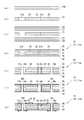
前記メタルコアプリント配線板15としてのメタルコア基板11は、図3に示したような工程を経て製造される。
この工程を説明すると、まず、コア板21となる所定厚の金属板(例えば銅板、アルミ板。)を裁断して素材21aを得る(図3(a)参照)。
続いて、この素材21aの所定位置に、所望の穴21bと前記分割溝23を形成する穴あけ加工を行って、コア板21を形成する(図3(b)参照)。このコア板21の一例を図4の平面図に示す。すなわち、コア板21は、複数の分割溝23と、これら分割溝23の間に介在する分離用接続部21dで囲まれた前記分割部分25を有している。
次に、コア板21の表面に、樹脂の密着性をよくするための粗化処理を施す。
この後、粗化処理済みのコア板21の両面にプリプレグ27と銅箔28を順に重ね(図3(c)参照)、ステンレス板(図示せず。)で挟んで、これらを加熱プレスによって積層一体化させる(図3(d)参照)。この一体化のときに、プリプレグ27の樹脂が前記穴21bと分割溝23の中に充填される。分割溝23に充填された樹脂が前記絶縁材22となる。
この積層一体化により、コア板21の両面に前記プリプレグ27で構成される絶縁層26を介して銅箔28が存在する構造となる。一体にしたものが銅張積層板16である。
つづいて、スルーホールを形成する所定位置には貫通孔16a、16bを形成し、前記分割溝23間の分離用接続部21d位置には貫通孔16cを形成する(図3(e)参照)。前記分離用接続部21d位置に形成した貫通孔16cによって、コア板21の分割部分25が、その周囲から分離されて電気的に独立となり、コア分割のメタルコア基板11aが得られる。なお、分割部分25を独立させるための前記貫通孔16cの形成は、前記絶縁層26の形成後であれば、どの段階で行ってもよい。
次に、前記スルーホールのための貫通孔16a,16bには、デスミア等の必要な処理をしてからメッキを施し、それぞれの貫通孔16a,16bの内周面とその近傍に通電部を形成する(図3(f)参照)。貫通孔16aのメッキは周知のスルーホールメッキ16dであり、スルーホールメッキ16dと前記コア板21は接触しない。一方、貫通孔16bではメッキ層16eがコア板21と電気的に接続する。このメッキ層16eは、コア板21を回路の一部として使うための接続孔を構成する通電部であり、必要に応じて形成され、図示しない端子が貫通孔16bに挿入されハンダ接続される。
この後、回路パターン29の形成、ソルダレジスト30の形成などの必要な処理を行うと、メタルコアプリント配線板15としてのメタルコア基板11aが得られる(図3(g)参照)。
このようなメタルコア基板11aを得るための前記コア板21の構造について説明すると、このコア板21は、放熱効果や小型化、搭載効率の向上に加えて、電子部品を積極的に熱から保護できるようにすべく構成されている。
図4に例示したコア板21では、便宜上分割部分25の全体の図示を省略しているが、コア板21には、複数の前記分割溝23が閉ループ状をなすように飛び飛びに形成され、これら分割溝23が形成されることによって前記分離用接続部21dと分割部分25が形成されることになる。
この分割溝23は、電子部品12,13を積極的に熱から保護できるようにするため、隣接する部分(本体部分24または分割部分25)からの熱伝達を制御できるように構成されている。すなわち、熱伝達を遮断または抑制できるような幅に形成されている。この幅は、搭載する電子部品12,13の耐熱温度または発熱温度に基づいて適宜設定される。たとえば分割部分25に、アルミ電解コンデンサなどの低耐熱の電子部品13を搭載し、本体部分24にCPUなどの発熱性の電子部品12を搭載するとよい。
分割溝23の幅のほか、分割溝23で形成される分割部分25の形態や配置も、搭載する電子部品12,13の耐熱温度または発熱温度に基づいて適宜設定される。
このようにすると、低耐熱の電子部品13を発熱性の電子部品12が発する熱から積極的に保護することができる。つまり、所定の電子部品が高温になることや回路材11が全体して高温になることを回避できる。この結果、同じ電子部品12,13でも、比較的廉価な低耐熱の電子部品12,13を使用することができて、コスト低減を図ることができるとともに、耐久性を向上できる。
また、1枚のメタルコア基板11aに複数の回路を形成できるので、複数のメタルコア基板を接続する場合に比して、部品点数を削減でき、コストの低減を図れるほか、小型化や積載効率の向上を図ることもできる。
なお、メタルコア基板11aの設計においては、耐熱温度が低い電子部品13と発熱温度が高い電子部品12をそれぞれまとめるとともに、これらをコア分割で区分できるようにする。極力まとめることによって、熱伝達を遮断しようとして分割溝23の幅が広くなった場合でも、メタルコア基板11aの小型化や搭載効率の向上を図ることができる。
図5は、回路材11としてのバスバー配索体11bの分解状態を示す斜視図である。この図に示すようにバスバー配索体11bは、合成樹脂製の1枚の前記絶縁板31と、この絶縁板31を表裏両面から挟む複数のバスバー32を有している。
前記絶縁板31は、所望の回路に応じて適宜の形状に形成されるが、前記複数のバスバー32を固定すべく、位置決め部としての複数の凹部33を表裏両面に有している。また、バスバー32の端子を挿通する挿通孔34を有するとともに、絶縁板31の表側に固定されるバスバー32の一部と裏側に固定されるバスバー32の一部を互いに絶縁板31の厚さ方向の中間において接合させる開口部35を有する。
前記バスバー32は、周知の通り銅合金材等のプレス打ち抜きで形成され、前記絶縁板31に固定されたときの全体形状としては所望の回路に応じた適宜の形状となるが、前記のように複数のバスバー32で構成されているため、固定前はばらばらの状態である。換言すれば、従来一枚の材料で構成されていたバスバーを複数に分割したような構造である。
複数のバスバー32は、所望の回路に応じて固定位置に相応しい形態に形成されている。また、バスバー32のうち絶縁板31の表面側のバスバー32と裏面側のバスバー32が絶縁板31を表裏両面から挟んだ時に表裏方向から相互に接合する接合部36が、バスバー32の一部に形成されている。これは、異層接続を可能にするためのもので、表面側のバスバー32または裏面側のバスバー32のいずれか一方または双方に、絶縁板31の厚さ方向に延びる脚部36aが設けられ、接合部36と前記脚部36aで断面略L字状をなすように形成される。
図6は、前記絶縁板31と、この絶縁板31の表面側に固定する複数のバスバー32を示す分解斜視図であり、組み付けに際しては、複数のバスバー32を絶縁板31の凹部33にそれぞれ固定すればよい。絶縁板31に対するバスバー32の固定は、例えば絶縁板31に対してバスバー32の表面から突出する溶着突起(図示せず)を形成しておき、バスバー32を載置してから前記溶着突起の頭部を押し広げるように溶着する方法など、周知の適宜の方法を利用できる。
このようにして複数のバスバー32を絶縁板31に固定すると、図7(a)に示したような状態になる。このとき、バスバー32の前記接合部36は相互に接合しているので、この部分の接続を保持するため、図7(b)に示したように接合部36に接合部同士を接続一体化する接続構造としてのTOX接続部37を形成する。このほか、接続構造は、例えば溶接等で構成することもできる。
なお、TOX接続とは、図7(c)の断面図に示したように、一方の金属板(接合部36)に形成した凹部37aの外側が、他方の金属板(接合部36)に形成された凹部37bの内側に圧入した構造となるように機械的に一体化することにより、複数の金属板を接続する方法である。加工に際して材料屑の発生がなく、加工が簡単であるなどの利点を有する。
このような構成のバスバー配索体11bでは、バスバー32の製造に際して歩留まりを良くすることができるので、材料にかかるコストを抑えられる。しかも、絶縁板31にはバスバー32を位置決めするための凹部33が形成されているので、絶縁板31に対する固定前にTOX接続する場合と異なり、TOX接続のための位置決め治具が不要となる。いわば絶縁板31が位置決め治具の役割を兼ねる。このため、加工にかかるコストを抑えることもできる。
また、治具を用いて正しく位置決めして行うTOX接続は作業性が良くなかったためTOX位置のずれ等の不良発生のおそれがあったが、前記のようにバスバー32の位置は絶縁板31で規制され加工が容易になるとともに、すべてのバスバー32が正しい位置関係で接続した状態で加工がなされることになるため、接続不良の発生のおそれや、例えばバスバー32を絶縁板に固定したときにバスバー32やそのTOX接続部分に歪が発生するおそれもない。このため、熱膨張に起因して接続部分等に支障をきたすようなことをなくすことができる。つまり、高温になった場合の不測の損傷を回避でき、耐久性を向上できる。
さらに、バスバー32が前記接合部36を有するので、異層接続・交差が1枚の絶縁板31で実現できる。このため、絶縁板31を複数に分割する構造に比して、簡素な構造となり、組立て工数や絶縁板31製造のためのコストを抑えて、廉価な製造が可能である。
つぎに、回路ユニット51について説明する。
回路ユニット51は、回路材11としての前記メタルコア基板11aや前記バスバー配索体11bに前記電子部品12,13,14aやコネクタホルダ52、ヒューズホルダ55などを搭載して構成される。
回路ユニット51は、回路材11としての前記メタルコア基板11aや前記バスバー配索体11bに前記電子部品12,13,14aやコネクタホルダ52、ヒューズホルダ55などを搭載して構成される。
回路材11として、前記メタルコア基板11aとバスバー配索体11bを用いる場合には、具体的な図示は省略するが、メタルコア基板11aにコア板21を回路の一部として使うために形成した接続孔としての貫通孔16b(図1、図3(g)参照)に前記バスバー配索体11bのバスバー32を直接または間接的に接続するとよい。回路材11同士の接続が別体のコネクタを使わずに簡単に行えるので、部品点数の削減をし、コスト低減を図ることができる。
前記コネクタホルダ52及びヒューズホルダ55とこれらの搭載について説明すると、コネクタホルダ52は、たとえばワイヤハーネス(図示せず)を電気的に接続するためのコネクタ(図示せず)を着脱可能に接続するためのもので、図8に示したようにコネクタ端子52aを備え、その周囲に絶縁性を有する樹脂製のハウジング52bを有する。
このコネクタホルダ52は、図9に示したように、前記ハウジング52bの一部が、回路材11に対してねじ58で固定されている。なお、コネクタホルダ52は、この例においては図8に示したように、間隔をあけて2個、平行に配設されている。
前記ヒューズホルダ55は、ヒューズ56を接続するヒューズ端子57を備える。このヒューズホルダ55は、図示例において、2個、すなわち第1ヒューズホルダ55a及び第2ヒューズホルダ55bを備え、これらは上下に重ねられるように配設されて回路材11に搭載される。
回路材11側に固定される下側の第1ヒューズホルダ55aは、従来と同様に回路材11に対してねじ(図示せず)で固定される。第1ヒューズホルダ55a
の固定位置は、2個のコネクタホルダ52の端部を跨ぐような位置である。
の固定位置は、2個のコネクタホルダ52の端部を跨ぐような位置である。
そして、第1ヒューズホルダ55aに重ねる上側の第2ヒューズホルダ55bは、部品点数と組み付け工数の削減のため、前記コネクタホルダ52に対して圧入することで固定するように構成されている。
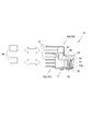
すなわち、回路材11に対してねじ58で固定した前記2個のコネクタホルダ52のハウジング52bに、厚さ方向に延びる前記嵌合孔53が形成されている。嵌合孔53は、図9に示したように厚さ方向に貫通する構造にして、コネクタホルダ52の固定のためのねじ58止めにも使用できる構造としている。なお、嵌合孔53は、ハウジング52bの上面側の必要部分のみに形成されるものであってもよい。
そして、第2ヒューズホルダ55bは、前記2個のコネクタホルダ52の上に跨って嵌合孔53の上面側に重なる重合部分59を有し、この重合部分59の下面に、前記嵌合孔53に嵌入する前記嵌入突起54が一体に形成されている。嵌入突起54は円柱状のものを図示したが、その他の形状のものであってもよい。
また、前記第1ヒューズホルダ55aと第2ヒューズホルダ55bのヒューズ端子57のヒューズ接続部側の部位には、相互に係合する係合部が形成されている。第1ヒューズホルダ55aには、図9の断面図に示したように上部における回路材11の内側部分が断面L字状に切り欠かれた形状の係合凹部60が形成される。
一方、第2ヒューズホルダ55bにおける前記係合凹部60に対向する部位には、断面L字状に突出する係合凸部61が形成されている。
このような構造の回路ユニット51においては、回路材11に対してコネクタホルダ52と第1ヒューズホルダ55aをねじで固定した後、第2ヒューズホルダ55bを、コネクタホルダ52に対して上から嵌合するだけで固定できる。この嵌合により、第2ヒューズホルダ55aの係合凸部61は、第1ヒューズホルダ55aの係合凹部60に係合し、第1ヒューズホルダ55aにかかるヒューズ56挿し込み時の荷重を受ける構造となる。
前記のように第2ヒューズホルダ55bの固定にねじが不要であるので、部品点数の削減と作業の簡易化を図ってコストダウンを実現できる。
しかも、第2ヒューズホルダ55bに対するヒューズ56の挿抜時にかかるストレスは、嵌入突起54部分が受けるので、第2ヒューズホルダ55bのヒューズ端子57のはんだ部分に負荷がかかることを回避できる。また、第1ヒューズホルダ55aに対するヒューズ56の挿抜時にかかるストレスは固定に用いたねじ(図示せず)部分で受けるともに、第2ヒューズホルダ55bの嵌入突起54部分が受けるので、第1ヒューズホルダ55aのヒューズ端子57のはんだ部分に負荷がかかることも回避できる。特に、嵌入突起54を嵌入する嵌合孔53を、コネクタホルダ52のねじ58止めのための孔と共用しているので、上記の緩衝効果は極めて高い。このため、高温になったり冷却されたりすることを繰り返す環境下におかれた場合であっても、所望の機能を確保でき、信頼性と耐久性向上にも資する。
なお、図8、図9の例では、回路材11としてメタルコア基板11aを用いた例を示したが、バスバー配索体11bを用いた場合でも同様である。
最後に、車載電気接続箱71について説明する。
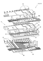
車載電気接続箱71は、回路材11としての前記メタルコア基板11aや前記バスバー配索体11b、前記回路ユニット51をロアケース72とアッパケース73などの筐体内に収容されて構成される。ロアケース72とアッパケース73の形態は、所望する回路に応じて適宜設定される。
このとき、さらに部品点数を削減し、コスト低減を図るとともに、耐久性の向上を図るためには、前記回路材11を収容する筐体におけるヒューズ56またはコネクタ(図示せず)を接続する接続端子の接続部分に、この接続端子の接続部分を囲繞するハウジング部を一体形成する。
図10は、別体のヒューズハウジング(図示せず)を省略した車載電気接続箱71の一例を示す分解斜視図である。
この図に示すように、ロアケース72とアッパケース73におけるヒューズ端子57のヒューズ接続側である接続部分に、接続部分を覆うように突出する第1ハウジング部72a、第2ハウジング部73aが一体に形成されている。
第1ハウジング部72aは、ロアケース72に形成され、上面が開口した略樋状または溝状をなしている。細かな形態は、接続部分等の形態に応じて適宜設定される。図10の例では、中電流用のヒューズ接続端子に対応する部分を樋状に形成し、小電流用のヒューズ接続端子に対応する部分を溝状に薄く形成した例を示している。このような形態の違いは、取り付けるヒューズ56の大きさの違いに基づくものである。
一方、第2ハウジング部73aは、アッパケース73に形成され、下面が開口した形状であり、前記第1ハウジング部72aと上下方向で係合することによって、中電流ヒューズ56aまたは小電流ヒューズ56bを囲繞する筒状をなす所定のハウジングを構成する。この場合も細かな形態は、接続部分等の形態に応じて適宜設定されるが、図10の例では、第2ハウジング部73aにおける中電流用のヒューズ56aを接続する部分は、第1ハウジング部72aの対応する部分よりも長く形成され、前記ハウジングの先端部を形成する方形枠状をなす額縁部73bを有している。額縁部73bを有することにより、ロアケース72とアッパケース73の一体性が増す。
このような構成の車載電気接続箱71では、別体のヒューズハウジングが不要であり、部品点数の削減ができ、組み付け作業の負担も軽減できる。このため、コストの低減を図ることができる。
また、ヒューズ56の挿抜時にハウジング部72a,73aにかかる負荷はロアケース72とアッパケース73で受けるので、ハウジングが別部材で構成された場合のように他の部分、例えば回路材11のはんだ部分などに負荷が伝達されて、余分なストレスが作用するおそれはない。このため高温になったり冷却されたりすることを繰り返す環境下におかれた場合であっても、所望の機能を確保でき、信頼性と耐久性向上にも資する。
なお、図10の例では、回路材11としてバスバー配索体11bを用いた例を示したが、メタルコア基板11aを用いた場合でも同様である。
以上のような回路材11や回路ユニット51、車載電気接続箱71によれば、材料や作業のためのコスト低減を図ることができるとともに、特に高温になることや高温になった場合の不都合を回避して、耐久性の良い車載電気接続箱71が得られる。
この発明の構成と、前記一形態の構成との対応において、
この発明の位置決め部は、凹部33に対応し、
以下同様に、
接続構造は、TOX接続部37に対応し、
接続孔は、貫通孔16bに対応し、
筐体は、ロアケース72とアッパケース73に対応し、
接続端子は、ヒューズ端子57に対応し、
ハウジングは、ハウジング部72a,73aに対応するも、
この発明は前記の構成のみに限定されるものではなく、その他の形態を採用することができる。
この発明の位置決め部は、凹部33に対応し、
以下同様に、
接続構造は、TOX接続部37に対応し、
接続孔は、貫通孔16bに対応し、
筐体は、ロアケース72とアッパケース73に対応し、
接続端子は、ヒューズ端子57に対応し、
ハウジングは、ハウジング部72a,73aに対応するも、
この発明は前記の構成のみに限定されるものではなく、その他の形態を採用することができる。
たとえば、位置決め部は、凹部のほか、バスバーに嵌る突起等で形成してもよい。
また、筐体と一体のハウジングは、コネクタを接続する部分に形成することができる。
11…回路材
11a…メタルコア基板
11b…バスバー配索体
12,13,14a…電子部品
16b…貫通孔
21…コア板
22…絶縁材
23…分割溝
24…本体部分
25…分割部分
31…絶縁板
32…バスバー
33…凹部
36…接合部
37…TOX接続部
51…回路ユニット
52…コネクタホルダ
53…嵌合孔
54…嵌入突起
55…ヒューズホルダ
57…ヒューズ端子
58…ねじ
71…車載電気接続箱
72…ロアケース
73…アッパケース
72a,73a…ハウジング部
11a…メタルコア基板
11b…バスバー配索体
12,13,14a…電子部品
16b…貫通孔
21…コア板
22…絶縁材
23…分割溝
24…本体部分
25…分割部分
31…絶縁板
32…バスバー
33…凹部
36…接合部
37…TOX接続部
51…回路ユニット
52…コネクタホルダ
53…嵌合孔
54…嵌入突起
55…ヒューズホルダ
57…ヒューズ端子
58…ねじ
71…車載電気接続箱
72…ロアケース
73…アッパケース
72a,73a…ハウジング部
Claims (11)
- 車載電気接続箱に収容される回路材であって、
当該回路材が、金属製のコア板を芯に有するメタルコア基板であり、
前記コア板が、絶縁材が充填された分割溝を介して本体部分と区切られた分割部分を有し、
前記本体部分を有する部分と分割部分を有する部分の双方に電子部品が搭載された
車載電気接続箱の回路材。 - 前記本体部分を有する部分と分割部分を有する部分とに搭載される電子部品が、耐熱温度又は発熱温度に基づいて区分された
請求項1に記載の回路材。 - 車載電気接続箱に収容される回路材であって、
当該回路材が、バスバーを有するバスバー配索体であり、
該バスバー配索体が、絶縁板と、該絶縁板を表裏両面から挟むバスバーを有するとともに、
前記絶縁体に、バスバーを位置決めする複数の位置決め部が形成され、
前記バスバーが、前記位置決め部に位置決めされる複数のバスバーで構成された
車載電気接続箱の回路材。 - 前記複数のバスバーには、バスバーのうち絶縁板の表面側のバスバーと裏面側のバスバーが絶縁板を表裏両面から挟んだ時に表裏方向から相互に接合する接合部が形成され、
これら接合部に、接合部同士を接続一体化する接続構造が形成された
請求項3に記載の車載電気接続箱の回路材。 - 車載電気接続箱に収容される回路ユニットであって、
当該回路ユニットを構成する回路材が、金属製のコア板を芯に有するメタルコア基板と、バスバーを有するバスバー配索体であり、
前記メタルコア基板のコア板が、絶縁材が充填された分割溝を介して本体部分と区切られた分割部分を有するとともに、
前記メタルコア基板には、前記コア板と電気的に接続する接続孔が形成され、
該接続孔に、前記バスバー配索体のバスバーが接続された
車載電気接続箱の回路ユニット。 - 前記バスバー配索体が、請求項3または請求項4に記載の回路材である
請求項5に記載の回路ユニット。 - 車載電気接続箱に収容される回路ユニットであって、
当該回路ユニットを構成する回路材上に、コネクタホルダが固定されるとともに、
該コネクタホルダの上面には嵌合孔が形成され、
該嵌合孔に嵌入する嵌入突起を下面に有するヒューズホルダが設けられ、
該ヒューズホルダが、前記嵌合孔と嵌入突起の相互の嵌合により、コネクタホルダ上に固定された
車載電気接続箱の回路ユニット。 - 前記回路材が、請求項1から請求項4のうちのいずれか一項に記載の回路材である
請求項7に記載の車載電気接続箱の回路ユニット。 - 前記コネクタホルダの固定が、回路材に対するネジ止めで行われるとともに、該ネジを螺合する孔が、前記嵌入孔と同一である
請求項7または請求項8に記載の車載電気接続箱の回路ユニット。 - 前記回路材を収容する筐体におけるヒューズまたはコネクタを接続する接続端子の接続部分に、該接続端子の接続部分を囲繞するハウジングが一体形成された
請求項1から請求項9に記載の回路材を収容する車載電気接続箱。 - 前記請求項1から請求項9のうちのいずれか一項に記載の回路材及び/又は回路ユニットを収容した
車載電気接続箱。
Priority Applications (2)
| Application Number | Priority Date | Filing Date | Title |
|---|---|---|---|
| CA2790265A CA2790265A1 (en) | 2010-02-19 | 2011-02-18 | Vehicle-mountable junction box, and circuit member and circuit unit usable for the vehicle-mountable junction box |
| US13/589,668 US20130044447A1 (en) | 2010-02-19 | 2012-08-20 | Vehicle-mountable junction box, and circuit member and circuit unit usable for the vehicle-mountable junction box |
Applications Claiming Priority (2)
| Application Number | Priority Date | Filing Date | Title |
|---|---|---|---|
| JP2010034353A JP5307052B2 (ja) | 2010-02-19 | 2010-02-19 | 車載電気接続箱、及びこれに用いられる回路材、回路ユニット |
| JP2010-034353 | 2010-02-19 |
Related Child Applications (1)
| Application Number | Title | Priority Date | Filing Date |
|---|---|---|---|
| US13/589,668 Continuation US20130044447A1 (en) | 2010-02-19 | 2012-08-20 | Vehicle-mountable junction box, and circuit member and circuit unit usable for the vehicle-mountable junction box |
Publications (1)
| Publication Number | Publication Date |
|---|---|
| WO2011102468A1 true WO2011102468A1 (ja) | 2011-08-25 |
Family
ID=44483053
Family Applications (1)
| Application Number | Title | Priority Date | Filing Date |
|---|---|---|---|
| PCT/JP2011/053520 Ceased WO2011102468A1 (ja) | 2010-02-19 | 2011-02-18 | 車載電気接続箱、及びこれに用いられる回路材、回路ユニット |
Country Status (4)
| Country | Link |
|---|---|
| US (1) | US20130044447A1 (ja) |
| JP (1) | JP5307052B2 (ja) |
| CA (1) | CA2790265A1 (ja) |
| WO (1) | WO2011102468A1 (ja) |
Families Citing this family (6)
| Publication number | Priority date | Publication date | Assignee | Title |
|---|---|---|---|---|
| JP5813387B2 (ja) * | 2011-06-21 | 2015-11-17 | 矢崎総業株式会社 | 電気接続箱 |
| JP2016015821A (ja) * | 2014-07-02 | 2016-01-28 | 株式会社オートネットワーク技術研究所 | 電気接続箱 |
| JP6120822B2 (ja) * | 2014-11-28 | 2017-04-26 | 矢崎総業株式会社 | 電気接続箱 |
| US10395878B2 (en) * | 2016-05-24 | 2019-08-27 | Eaton Intelligent Power Limited | Modular fuse holder and arrangement and connection thereof |
| JP6499124B2 (ja) * | 2016-06-30 | 2019-04-10 | 矢崎総業株式会社 | 導電部材および電気接続箱 |
| JP6618510B2 (ja) * | 2017-07-04 | 2019-12-11 | 矢崎総業株式会社 | 電気接続箱、及び、ワイヤハーネス |
Citations (9)
| Publication number | Priority date | Publication date | Assignee | Title |
|---|---|---|---|---|
| JPH069063U (ja) * | 1992-07-07 | 1994-02-04 | 古河電気工業株式会社 | 電気接続箱内導電体の接続構造 |
| JP2000299911A (ja) * | 1999-04-13 | 2000-10-24 | Yazaki Corp | 電気接続箱 |
| JP2002064921A (ja) * | 2000-08-17 | 2002-02-28 | Furukawa Electric Co Ltd:The | 基板用コネクタおよび該基板用コネクタを用いた電気接続箱 |
| JP2006339545A (ja) * | 2005-06-06 | 2006-12-14 | Furukawa Electric Co Ltd:The | メタルコア回路基板 |
| JP2007228757A (ja) * | 2006-02-24 | 2007-09-06 | Furukawa Electric Co Ltd:The | 電気接続箱 |
| JP2007311152A (ja) * | 2006-05-18 | 2007-11-29 | Furukawa Electric Co Ltd:The | 配線基板ユニット |
| JP2009153319A (ja) * | 2007-12-21 | 2009-07-09 | Yazaki Corp | 板状端子の組付構造 |
| JP2009153320A (ja) * | 2007-12-21 | 2009-07-09 | Yazaki Corp | バスバーブロックの組付構造 |
| JP2009284622A (ja) * | 2008-05-21 | 2009-12-03 | Yazaki Corp | 電気接続箱の電源分配構造 |
Family Cites Families (4)
| Publication number | Priority date | Publication date | Assignee | Title |
|---|---|---|---|---|
| US5229922A (en) * | 1991-09-26 | 1993-07-20 | Yazaki Corporation | Electrical junction box with stacked insulating plates and bus-bars with stepped tabs |
| JP4161877B2 (ja) * | 2003-11-05 | 2008-10-08 | 住友電装株式会社 | 回路構成体、その製造方法及び配電ユニット |
| JP4868928B2 (ja) * | 2006-04-26 | 2012-02-01 | 矢崎総業株式会社 | ジャンクションブロック |
| JP5026947B2 (ja) * | 2007-12-21 | 2012-09-19 | 矢崎総業株式会社 | 回路基板の熱対策構造 |
-
2010
- 2010-02-19 JP JP2010034353A patent/JP5307052B2/ja active Active
-
2011
- 2011-02-18 WO PCT/JP2011/053520 patent/WO2011102468A1/ja not_active Ceased
- 2011-02-18 CA CA2790265A patent/CA2790265A1/en not_active Abandoned
-
2012
- 2012-08-20 US US13/589,668 patent/US20130044447A1/en not_active Abandoned
Patent Citations (9)
| Publication number | Priority date | Publication date | Assignee | Title |
|---|---|---|---|---|
| JPH069063U (ja) * | 1992-07-07 | 1994-02-04 | 古河電気工業株式会社 | 電気接続箱内導電体の接続構造 |
| JP2000299911A (ja) * | 1999-04-13 | 2000-10-24 | Yazaki Corp | 電気接続箱 |
| JP2002064921A (ja) * | 2000-08-17 | 2002-02-28 | Furukawa Electric Co Ltd:The | 基板用コネクタおよび該基板用コネクタを用いた電気接続箱 |
| JP2006339545A (ja) * | 2005-06-06 | 2006-12-14 | Furukawa Electric Co Ltd:The | メタルコア回路基板 |
| JP2007228757A (ja) * | 2006-02-24 | 2007-09-06 | Furukawa Electric Co Ltd:The | 電気接続箱 |
| JP2007311152A (ja) * | 2006-05-18 | 2007-11-29 | Furukawa Electric Co Ltd:The | 配線基板ユニット |
| JP2009153319A (ja) * | 2007-12-21 | 2009-07-09 | Yazaki Corp | 板状端子の組付構造 |
| JP2009153320A (ja) * | 2007-12-21 | 2009-07-09 | Yazaki Corp | バスバーブロックの組付構造 |
| JP2009284622A (ja) * | 2008-05-21 | 2009-12-03 | Yazaki Corp | 電気接続箱の電源分配構造 |
Also Published As
| Publication number | Publication date |
|---|---|
| JP2011172392A (ja) | 2011-09-01 |
| CA2790265A1 (en) | 2011-08-25 |
| US20130044447A1 (en) | 2013-02-21 |
| JP5307052B2 (ja) | 2013-10-02 |
Similar Documents
| Publication | Publication Date | Title |
|---|---|---|
| JP4453726B2 (ja) | 車載用のジャンクションボックス | |
| JP5307052B2 (ja) | 車載電気接続箱、及びこれに用いられる回路材、回路ユニット | |
| US6444911B2 (en) | Bus bar wiring plate body for electric coupling box | |
| CN103515889B (zh) | 电气连接箱 | |
| KR20190139287A (ko) | 회로 구성체 | |
| WO2015170583A1 (ja) | 回路構成体および電気接続箱 | |
| CN104021933A (zh) | 电子部件和电子控制单元 | |
| JP3722702B2 (ja) | 車載電子機器 | |
| CN111034383B (zh) | 电子单元 | |
| CN106256063B (zh) | 电路结构体及电连接箱 | |
| JP2006060956A (ja) | 電気接続箱 | |
| JP5587152B2 (ja) | 電気接続箱 | |
| JP2007128929A (ja) | メタルコア基板及びその製造方法並びに電気接続箱 | |
| JP2007109993A (ja) | 回路基板内蔵筐体 | |
| JP5590713B2 (ja) | 配線基板及びその製造方法 | |
| JP2011071344A (ja) | 回路ユニット | |
| JP5367669B2 (ja) | 車両用の電気接続箱 | |
| JP5511338B2 (ja) | 基板取付体 | |
| JP4860800B2 (ja) | パワー回路配線構造の製造方法 | |
| JP4762784B2 (ja) | 配線基板ユニット | |
| JP2002078159A (ja) | 電気部品取付構造および該取付構造を備えたジャンクションボックス | |
| CN102726126A (zh) | 车载电气连接箱用金属芯基板 | |
| JP4676304B2 (ja) | 基板モジュールおよび電気接続箱 | |
| JP4728873B2 (ja) | 配線基板ユニット | |
| JP2007259539A (ja) | 車載用電気接続箱 |
Legal Events
| Date | Code | Title | Description |
|---|---|---|---|
| 121 | Ep: the epo has been informed by wipo that ep was designated in this application |
Ref document number: 11744754 Country of ref document: EP Kind code of ref document: A1 |
|
| ENP | Entry into the national phase |
Ref document number: 2790265 Country of ref document: CA |
|
| NENP | Non-entry into the national phase |
Ref country code: DE |
|
| 122 | Ep: pct application non-entry in european phase |
Ref document number: 11744754 Country of ref document: EP Kind code of ref document: A1 |