WO2011099209A1 - Véhicule deux-roues motorisé du type scooter - Google Patents
Véhicule deux-roues motorisé du type scooter Download PDFInfo
- Publication number
- WO2011099209A1 WO2011099209A1 PCT/JP2010/070584 JP2010070584W WO2011099209A1 WO 2011099209 A1 WO2011099209 A1 WO 2011099209A1 JP 2010070584 W JP2010070584 W JP 2010070584W WO 2011099209 A1 WO2011099209 A1 WO 2011099209A1
- Authority
- WO
- WIPO (PCT)
- Prior art keywords
- control device
- hydraulic control
- vehicle body
- disposed
- right direction
- Prior art date
Links
Images


Classifications
-
- B—PERFORMING OPERATIONS; TRANSPORTING
- B60—VEHICLES IN GENERAL
- B60T—VEHICLE BRAKE CONTROL SYSTEMS OR PARTS THEREOF; BRAKE CONTROL SYSTEMS OR PARTS THEREOF, IN GENERAL; ARRANGEMENT OF BRAKING ELEMENTS ON VEHICLES IN GENERAL; PORTABLE DEVICES FOR PREVENTING UNWANTED MOVEMENT OF VEHICLES; VEHICLE MODIFICATIONS TO FACILITATE COOLING OF BRAKES
- B60T8/00—Arrangements for adjusting wheel-braking force to meet varying vehicular or ground-surface conditions, e.g. limiting or varying distribution of braking force
- B60T8/32—Arrangements for adjusting wheel-braking force to meet varying vehicular or ground-surface conditions, e.g. limiting or varying distribution of braking force responsive to a speed condition, e.g. acceleration or deceleration
- B60T8/34—Arrangements for adjusting wheel-braking force to meet varying vehicular or ground-surface conditions, e.g. limiting or varying distribution of braking force responsive to a speed condition, e.g. acceleration or deceleration having a fluid pressure regulator responsive to a speed condition
- B60T8/36—Arrangements for adjusting wheel-braking force to meet varying vehicular or ground-surface conditions, e.g. limiting or varying distribution of braking force responsive to a speed condition, e.g. acceleration or deceleration having a fluid pressure regulator responsive to a speed condition including a pilot valve responding to an electromagnetic force
- B60T8/3615—Electromagnetic valves specially adapted for anti-lock brake and traction control systems
- B60T8/3675—Electromagnetic valves specially adapted for anti-lock brake and traction control systems integrated in modulator units
- B60T8/368—Electromagnetic valves specially adapted for anti-lock brake and traction control systems integrated in modulator units combined with other mechanical components, e.g. pump units, master cylinders
- B60T8/3685—Electromagnetic valves specially adapted for anti-lock brake and traction control systems integrated in modulator units combined with other mechanical components, e.g. pump units, master cylinders characterised by the mounting of the modulator unit onto the vehicle
-
- B—PERFORMING OPERATIONS; TRANSPORTING
- B62—LAND VEHICLES FOR TRAVELLING OTHERWISE THAN ON RAILS
- B62J—CYCLE SADDLES OR SEATS; AUXILIARY DEVICES OR ACCESSORIES SPECIALLY ADAPTED TO CYCLES AND NOT OTHERWISE PROVIDED FOR, e.g. ARTICLE CARRIERS OR CYCLE PROTECTORS
- B62J45/00—Electrical equipment arrangements specially adapted for use as accessories on cycles, not otherwise provided for
-
- B—PERFORMING OPERATIONS; TRANSPORTING
- B62—LAND VEHICLES FOR TRAVELLING OTHERWISE THAN ON RAILS
- B62K—CYCLES; CYCLE FRAMES; CYCLE STEERING DEVICES; RIDER-OPERATED TERMINAL CONTROLS SPECIALLY ADAPTED FOR CYCLES; CYCLE AXLE SUSPENSIONS; CYCLE SIDE-CARS, FORECARS, OR THE LIKE
- B62K11/00—Motorcycles, engine-assisted cycles or motor scooters with one or two wheels
- B62K11/02—Frames
- B62K11/10—Frames characterised by the engine being over or beside driven rear wheel
-
- B—PERFORMING OPERATIONS; TRANSPORTING
- B62—LAND VEHICLES FOR TRAVELLING OTHERWISE THAN ON RAILS
- B62K—CYCLES; CYCLE FRAMES; CYCLE STEERING DEVICES; RIDER-OPERATED TERMINAL CONTROLS SPECIALLY ADAPTED FOR CYCLES; CYCLE AXLE SUSPENSIONS; CYCLE SIDE-CARS, FORECARS, OR THE LIKE
- B62K2202/00—Motorised scooters
Definitions
- the present invention relates to a scooter type motorcycle.
- the present invention relates to a scooter type motorcycle equipped with an anti-lock brake device that brakes the wheels without locking them.
- the anti-lock brake device for scooter disclosed in Patent Document 1 includes a hydraulic control device that performs control to increase or decrease the hydraulic pressure in the hydraulic system of the front wheel side disc brake and the hydraulic system of the rear wheel side disc brake.
- This hydraulic control device is supported by the head pipe via a bracket, in front of the vehicle body frame and at the front of the vehicle body.
- the present invention has been made in view of the above-mentioned problems, and in a scooter type motorcycle equipped with an anti-lock brake device, the mass is concentrated near the center of gravity of the vehicle body and the steering stability is improved. The purpose is to let you.
- the scooter type motorcycle according to the present invention has a cylinder unit extending in the front-rear direction below the seating seat, and extends rearward from one side in the left-right direction of the crankcase to transmit power to the rear wheels.
- An anti-lock brake device having a unit swing type engine that is integrally provided with the device and supported so as to be swingable up and down with respect to the vehicle body, and a hydraulic control device that controls the hydraulic pressure of the hydraulic brake so as not to lock the wheels;
- the hydraulic control device is disposed below the seating seat, on the other side in the left-right direction of the vehicle body, and above the side of the cylinder unit.
- an air-fuel mixture supply device that supplies an air-fuel mixture to the cylinder unit is provided on one side in the left-right direction of the vehicle body, and the hydraulic control device is configured to include the air-fuel mixture supply device that sandwiches the cylinder unit in a plan view. It is the other side and is arrange
- a pivot shaft for supporting a shaft support portion protruding from the unit swing type engine is further provided, and the hydraulic control device is disposed in front of the pivot shaft.
- the hydraulic control device further includes a rear brake caliper whose hydraulic pressure is controlled, and the rear brake caliper is disposed on the other side in the left-right direction of the vehicle body.
- the mass in a scooter type motorcycle equipped with an anti-lock brake device, can be concentrated near the center of gravity of the vehicle body, and the steering stability can be improved.
- FIG. 1 is a right side view of a scooter type motorcycle according to the present embodiment.
- FIG. 2 is a right side view of the scooter type motorcycle according to this embodiment with the cowling removed.
- FIG. 3 is a left side view of the scooter type motorcycle according to this embodiment with the cowling removed.
- FIG. 4 is a plan view of the scooter type motorcycle according to this embodiment with the cowling removed.
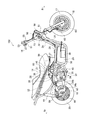
- FIG. 5 is a perspective view showing the periphery of the hydraulic control apparatus according to the present embodiment.
- FIG. 6 is a perspective view showing the periphery of the hydraulic control apparatus with the suspension bridge according to the present embodiment removed.
- FIG. 1 is a right side view of a scooter type motorcycle according to the present embodiment.
- the front of the vehicle body is indicated by arrow Fr
- the rear of the vehicle body is indicated by arrow Rr
- the right side of the vehicle body is indicated by arrow R
- the left side of the vehicle body is indicated by arrow L as necessary.
- a scooter type motorcycle 100 (hereinafter referred to as a motorcycle) has a plurality of body frames, which will be described later, made of steel or aluminum alloy as a skeleton.
- the vehicle body frame is covered with a plurality of cowlings such as the front leg shield 11, the center leg shield 12, and the frame cover 13, so that the appearance of the vehicle body is adjusted.
- a floor board 15 on which the occupant's legs seated on the seating seat 14 are placed is provided.
- a steering handle bar 16 for steering is disposed in the left-right direction in front of the vehicle body.
- a pair of front forks 17 whose directions change from side to side by steering by the handle bar 16 are provided at the lower front part of the handle bar 16.
- the pair of front forks 17 pivotally support the front wheel 18 so as to be rotatable.
- a swing arm 19 is provided at the rear of the vehicle body so as to be able to swing up and down together with the unit swing type engine 33.
- a rear wheel 20 is pivotally supported at the rear ends of the power transmission device 40 (see FIG. 3) of the swing arm 19 and the unit swing type engine 33.
- a muffler 21 is coupled to the swing arm 19.
- FIG. 2 is a right side view of the vehicle body with the cowling removed.
- FIG. 3 is a left side view of the state where the cowling is removed.
- FIG. 4 is a plan view of the vehicle body with the cowling removed.
- a steering head pipe 22 is disposed in front of the motorcycle 100 between the handle bar 16 and the front fork 17 described above.
- a steering shaft 23 that connects the handle bar 16 and the front fork 17 is rotatably inserted into the steering head pipe 22.
- the steering head pipe 22 has an upper pipe 24 as a vehicle body frame extending obliquely downward and rearward from substantially the center.
- a pair of left and right lower pipes 25 extend rearward and obliquely downward from the lower end of the steering head pipe 22 so as to be substantially parallel to the upper pipe 24.
- Coupled to each lower pipe 25 is a pair of left and right main pipes 26 that diverge from the middle and extend in a substantially horizontal direction toward the rear of the vehicle body.
- the main pipe 26 extends rearward in a substantially horizontal direction, and then extends rearward and obliquely upward from a position close to the rear wheel 20 to the rear portion of the vehicle body.
- Each lower pipe 25 extends from the lower side of the vehicle body to the rear in a substantially horizontal direction, and then extends obliquely rearward and upward to be coupled to each main pipe 26.
- the pair of main pipes 26 are curved so as to approach each other in the rear direction after being separated from each other in the left-right direction from the front toward the rear.
- the pair of main pipes 26 are coupled via a seat hinge bridge 27, a suspension bridge 28, and the like.
- FIG. 5 is a perspective view of the center portion of the vehicle body as viewed from above.
- a fuel tank 29 is disposed in a space surrounded by the pair of main pipes 26 and the pair of lower pipes 25.
- a battery 30 is disposed on the right side of the fuel tank 29 and above the lower pipe 25 on the right side. As shown by a broken line in FIG. 1, the battery 30 is located below the floor board 15.
- a seat hinge 31 is coupled to the upper surface of the seat hinge bridge 27.
- the seat hinge 31 is pivotally supported so as to be openable and closable around the front end portion of the seating seat 14.
- a luggage box 32 having an accommodation space formed therein is disposed below the seating seat 14. 2 and 3, a part of the luggage box 32 hidden by the seating seat 14 is indicated by a broken line.
- the luggage box 32 has a size from the front end portion to the rear end portion of the seating seat 14 and is covered by the seating seat 14 from above.
- a unit swing type engine 33 is disposed below the seating seat 14, specifically below the luggage box 32 and in the center in the left-right direction of the vehicle body.
- the unit swing type engine 33 includes a crankcase 34 that supports a crankshaft (not shown), a cylinder unit 35 in which a piston (not shown) slides, a power transmission device 40 (see FIG. 3), and the like.
- the crankcase 34 is located in front of the rear wheel 20 and below the suspension bridge 28.
- the cylinder unit 35 extends in the front-rear direction, specifically, slightly forward and obliquely upward from the crankcase 34.
- FIG. 6 is a perspective view of the center of the vehicle body showing a state in which the above-described suspension bridge 28 is removed. As shown in FIG. 6, a pair of shaft support portions 34 c and 34 d protrude from the left and right sides of the upper portion of the crankcase 34 to support the first pivot shaft 36. A pair of pivot brackets 37 (see FIG.
- the first pivot shaft 36 and the second pivot shaft 38 are located in the suspension bridge 28 formed in a triangular prism shape, but the first pivot shaft 36 is notched in the suspension bridge 28. It can be seen from the right side shown in FIG. 2 through the hole 28a (see FIG. 5). Further, since the end portion of the second pivot shaft 38 is also pivotally supported by the pivot bracket 37, it can be seen in the drawings shown in FIGS.
- a power transmission device 40 that transmits the rotation of the crankshaft to the rear wheel 20 is disposed on the left side of the crankcase 34.
- the power transmission device 40 has a long shape along the front-rear direction, and is disposed from the crankcase 34 to the rear wheel 20.
- the power transmission device 40 pivotally supports the rear wheel 20 from the left side together with the above-described swing arm 19 located on the right side of the vehicle body. Further, the power transmission device 40 can swing around the first pivot shaft 36 integrally with the crankcase 34 and the cylinder unit 35.
- a second shock absorber 42 is disposed between the rear end portion of the power transmission device 40 and the rear portion of the left main pipe 26.
- an air cleaner box 43 is disposed on the upper portion of the power transmission device 40.
- a connection tube 44 is connected to the front end of the air cleaner box 43.
- the connection tube 44 passes between the luggage box 32 and the left main pipe 26 and is connected to an unillustrated intake port at the top of the cylinder unit 35 as shown in FIGS. 5 and 6.
- An air-fuel mixture supply device 45 is disposed between the cylinder unit 35 and the connection tube 44.
- a fuel injector (not shown) is disposed in the air-fuel mixture supply device 45 and supplies the air-fuel mixture mixed with fuel to the cylinder unit 35.
- the air-fuel mixture supply device 45 is disposed obliquely above and to the left of the cylinder unit 35.
- the air-fuel mixture supplied to the cylinder unit 35 is combusted in a combustion chamber (not shown), slides the piston, and rotates the crankshaft. Further, the exhaust gas generated when combusting is exhausted from the muffler 21 through the exhaust pipe 46 shown in FIG. 2 connected to an exhaust port (not shown) below the cylinder unit 35.
- an anti-lock brake device having a hydraulic control device 50 that controls the hydraulic brakes of the front wheels 18 and the rear wheels 20 so as not to lock the front wheels 18 and the rear wheels 20 during braking.
- the antilock brake device includes an electronic control device, a master cylinder, a brake hose, a brake caliper, and the like, which will be described later, in addition to the hydraulic control device 50.
- a front brake lever 51 and a front brake master cylinder 53 are disposed on the right side of the handle bar 16.
- a rear brake lever 52 and a rear brake master cylinder 54 are disposed on the left side of the handle bar 16.
- a front brake hose upper 55 is connected to the front brake master cylinder 53, and a rear brake hose upper 56 is connected to the rear brake master cylinder 54.
- the front brake hose upper 55 and the rear brake hose upper 56 are lowered so as to substantially follow the steering shaft 23 and are connected to the inlet-side front brake pipe 57 and the inlet-side rear brake pipe 58, respectively.
- the inlet-side front brake pipe 57 and the inlet-side rear brake pipe 58 are respectively routed along the lower pipe 25 and the main pipe 26 from the steering head pipe 22 and are arranged in the main pipe 26 on the right side of the vehicle body. It is connected to the device 50.
- an outlet side front brake pipe 59 and an outlet side rear brake pipe 60 are connected to the hydraulic control device 50.
- the outlet-side front brake pipe 59 is routed from the hydraulic control device 50 to the front of the steering head pipe 22 through the same path as the inlet-side front brake pipe 57 and is connected to the front brake hose lower 61.
- the front brake hose lower 61 is lowered toward the front wheel 18 along the steering head pipe 22, and then connected to a front brake caliper 62 as a hydraulic brake for the front wheel 18.
- the front brake caliper 62 is coupled to the right front fork 17 and brakes the front wheel 18 by clamping the front brake disc 63 that rotates in synchronization with the front wheel 18 from both sides.
- the outlet-side rear brake pipe 60 extends rearward along the right main pipe 26 and is connected to the rear brake hose 64.
- the rear brake hose 64 extends toward the rear wheel 20 along the swing arm 19 and is then connected to a rear brake caliper 65 as a hydraulic brake for the rear wheel 20.
- the rear brake caliper 65 is coupled to the swing arm 19 and brakes the rear wheel 20 by pressing the rear brake disc 66 that rotates in synchronization with the rear wheel 20 from both sides.
- the hydraulic control device 50 includes a motor 50 a and a hydraulic pump 50 b driven by the motor 50 a.
- the hydraulic pump 50b includes a solenoid valve (not shown) for increasing or decreasing the hydraulic pressure with respect to the front brake caliper 62 and the rear brake caliper 65.
- the hydraulic control device 50 incorporates an electronic control device (not shown). The electronic control device transmits a control signal to the hydraulic control device 50 when it detects a predetermined deceleration or more of the front wheels 18 and the rear wheels 20 via a front wheel speed sensor (not shown) or a rear wheel speed sensor (not shown).
- the hydraulic control device 50 reduces or increases the hydraulic pressure with respect to the front brake caliper 62 and the rear brake caliper 65 so as not to exceed a predetermined deceleration according to the control signal.
- the hydraulic control device 50 and the electronic control device are supplied with power from the battery 30.
- the motorcycle 100 can be braked so that the front wheel 18 and the rear wheel 20 are not locked by the anti-lock brake device.
- the hydraulic control device 50 is a heavy object including the motor 50a and the like, the controllability of the motorcycle 100 is affected depending on the position where the hydraulic control device 50 is attached.
- the hydraulic control device 50 is disposed at a position where the steering stability of the motorcycle 100 is improved.
- attachment of the hydraulic control device 50 will be described in detail.
- the hydraulic control device 50 is disposed below the seating seat 14, more specifically below the luggage box 32 in a side view.
- the hydraulic control device 50 is located between the seat hinge bridge 27 and the suspension bridge 28 and in front of the first pivot shaft 36. Further, as shown in FIGS.
- the hydraulic control device 50 is located at a position close to the cylinder unit 35, more specifically, at an upper right side (upward side) of the cylinder unit 35. As described above, since the hydraulic control device 50 is disposed in the vicinity of the center of gravity of the vehicle body, the mass is concentrated, and the steering stability of the motorcycle 100 is improved.
- the hydraulic control device 50 is disposed on the right main pipe 26. More specifically, the hydraulic control device 50 uses a plurality of fixing bolts 70 via a mounting plate 50 c on a mounting bracket 26 a installed on the main pipe 26 and a mounting bracket 28 b formed on the suspension bridge 28. Are combined. As described above, by disposing the hydraulic control device 50 in the main pipe 26, the mounting bracket 26a can be reduced in size, can be reduced in weight, and can be manufactured at low cost. Further, an anti-vibration elastic body 71 is sandwiched between the mounting plate 50 c and the fixing bolt 70. In other words, the hydraulic control device 50 is floatingly fastened by the elastic body 71. The elastic body 71 prevents the vibration of the motor 50a of the hydraulic control device 50 from being transmitted to the vehicle body, and conversely prevents the vibration of the vehicle body from being transmitted to the hydraulic control device 50.
- the hydraulic control device 50 is disposed on the right side of the vehicle body, which is the opposite side of the power transmission device 40 disposed on the left side of the vehicle body, the left and right balance of the vehicle body is balanced, and the motorcycle 100 steering stability is improved. Further, as shown in FIGS. 5 and 6, the hydraulic control device 50 and the air-fuel mixture supply device 45 are arranged so as to be distributed to the left and right with the cylinder unit 35 interposed therebetween. Can be made substantially the same height as the air-fuel mixture supply device 45. That is, since the hydraulic control device 50 can be disposed further downward, the center of gravity of the vehicle body is lowered and the steering stability is improved. Furthermore, by arranging the hydraulic control device 50 further downward, the inside of the luggage box 32 can be formed widely and the height of the seating seat 14 can be reduced.
- the hydraulic control device 50 is disposed slightly inclined with respect to the longitudinal direction of the vehicle body. More specifically, the line connecting the tangent lines of the outer shape of the hydraulic control device 50 (see the two-dot chain line L shown in FIG. 5) is inclined so as to be substantially parallel to the adjacent right main pipe 26. . Therefore, the hydraulic pressure control device 50 can be arranged so as to be deviated to the right side as much as possible within a range that does not contact the right side center leg shield 12 adjacent to the main pipe 26 and the cowling as the frame cover 13. It is possible to balance the left and right balance of the vehicle body.
- the battery 30 that supplies power to the hydraulic control device 50 is also on the right side in the left-right direction and on the same side as the hydraulic control device 50, a wiring cord (not shown) from the battery 30 to the hydraulic control device 50 can be shortened.
- the motorcycle 100 can be reduced in weight and manufactured at low cost. Furthermore, by shortening the wiring cord, voltage drop due to wiring resistance is reduced and power performance is improved.
- the hydraulic control device 50 By disposing the hydraulic control device 50 at the position as described above, the mass can be concentrated near the center of gravity of the motorcycle 100, and the steering stability can be improved.
- the hydraulic control device 50 is disposed on the right side of the vehicle body and the power transmission device 40 is disposed on the left side of the vehicle body has been described, but the present invention is not limited to this case. That is, if the hydraulic control device 50 is disposed on the side opposite to the side where the power transmission device 40 is disposed in the left-right direction of the vehicle body, the left-right balance of the vehicle body can be balanced.
- the hydraulic control device 50 has been described using the mounting bracket 26a installed on the main pipe 26 and the mounting bracket 28b formed on the suspension bridge 28. In this case, Not limited. That is, it may be a mounting bracket installed on any member. Moreover, although this embodiment demonstrated the case where the hydraulic control apparatus 50 was arrange
- the present invention can be used for a scooter type motorcycle equipped with an anti-lock brake device.
Landscapes
- Engineering & Computer Science (AREA)
- Mechanical Engineering (AREA)
- Physics & Mathematics (AREA)
- Electromagnetism (AREA)
- Fluid Mechanics (AREA)
- Transportation (AREA)
- Regulating Braking Force (AREA)
- Automatic Cycles, And Cycles In General (AREA)
- Axle Suspensions And Sidecars For Cycles (AREA)
- Motorcycle And Bicycle Frame (AREA)
Abstract
Priority Applications (4)
| Application Number | Priority Date | Filing Date | Title |
|---|---|---|---|
| JP2011553718A JP5673563B2 (ja) | 2010-02-09 | 2010-11-18 | スクータ型自動二輪車 |
| ES10845800.1T ES2626304T3 (es) | 2010-02-09 | 2010-11-18 | Motocicleta de tipo scooter |
| EP10845800.1A EP2535249B1 (fr) | 2010-02-09 | 2010-11-18 | Véhicule motorisé du type scooter |
| CN201080063466.6A CN102753426B (zh) | 2010-02-09 | 2010-11-18 | 踏板式摩托车 |
Applications Claiming Priority (2)
| Application Number | Priority Date | Filing Date | Title |
|---|---|---|---|
| JP2010026954 | 2010-02-09 | ||
| JP2010-026954 | 2010-02-09 |
Publications (1)
| Publication Number | Publication Date |
|---|---|
| WO2011099209A1 true WO2011099209A1 (fr) | 2011-08-18 |
Family
ID=44367501
Family Applications (1)
| Application Number | Title | Priority Date | Filing Date |
|---|---|---|---|
| PCT/JP2010/070584 WO2011099209A1 (fr) | 2010-02-09 | 2010-11-18 | Véhicule deux-roues motorisé du type scooter |
Country Status (5)
| Country | Link |
|---|---|
| EP (1) | EP2535249B1 (fr) |
| JP (1) | JP5673563B2 (fr) |
| CN (1) | CN102753426B (fr) |
| ES (1) | ES2626304T3 (fr) |
| WO (1) | WO2011099209A1 (fr) |
Cited By (4)
| Publication number | Priority date | Publication date | Assignee | Title |
|---|---|---|---|---|
| JP2013103524A (ja) * | 2011-11-10 | 2013-05-30 | Honda Motor Co Ltd | 自動二輪車 |
| JP2013193647A (ja) * | 2012-03-22 | 2013-09-30 | Honda Motor Co Ltd | 鞍乗り型車両のフレーム構造 |
| WO2015079478A1 (fr) * | 2013-11-29 | 2015-06-04 | 川崎重工業株式会社 | Automobile à deux roues |
| EP4079587A1 (fr) * | 2021-04-23 | 2022-10-26 | Yamaha Hatsudoki Kabushiki Kaisha | Véhicule à enfourcher |
Families Citing this family (9)
| Publication number | Priority date | Publication date | Assignee | Title |
|---|---|---|---|---|
| JP6023576B2 (ja) * | 2012-12-17 | 2016-11-09 | 川崎重工業株式会社 | 自動二輪車 |
| CN104890660A (zh) * | 2015-06-24 | 2015-09-09 | 力帆实业(集团)股份有限公司 | 骑式摩托车abs控制器安装结构 |
| TWI623460B (zh) * | 2016-03-14 | 2018-05-11 | Kwang Yang Motor Co | Locomotive frame |
| JP6773428B2 (ja) * | 2016-03-23 | 2020-10-21 | 本田技研工業株式会社 | 鞍乗り型車両 |
| EP3366564B1 (fr) * | 2017-02-28 | 2020-07-15 | Yamaha Hatsudoki Kabushiki Kaisha | Véhicule à enfourcher |
| JP2019001208A (ja) * | 2017-06-12 | 2019-01-10 | スズキ株式会社 | 自動二輪車の車体構造 |
| TWI821553B (zh) * | 2019-04-10 | 2023-11-11 | 美商賀氏精密機械 | 懸吊組合 |
| CN112339897B (zh) * | 2019-08-08 | 2022-07-29 | 光阳工业股份有限公司 | 速克达型摩托车结构 |
| CN112265599B (zh) * | 2020-10-20 | 2022-04-15 | 河北井昌车业有限公司 | 一种自行车前刹防抱死装置 |
Citations (6)
| Publication number | Priority date | Publication date | Assignee | Title |
|---|---|---|---|---|
| JPH0316893A (ja) * | 1989-06-14 | 1991-01-24 | Yamaha Motor Co Ltd | スクータ型自動二輪車の油圧ブレーキ装置 |
| JPH11314591A (ja) * | 1998-05-06 | 1999-11-16 | Yamaha Motor Co Ltd | スクータ用アンチロックブレーキ装置 |
| JP2001310784A (ja) * | 2000-04-26 | 2001-11-06 | Honda Motor Co Ltd | スクータ型車両 |
| JP2002029395A (ja) * | 2000-07-19 | 2002-01-29 | Honda Motor Co Ltd | 車輪速度検出装置の取付構造 |
| JP2005145287A (ja) * | 2003-11-17 | 2005-06-09 | Honda Motor Co Ltd | 自動二輪車の制動力調整装置 |
| JP4298810B2 (ja) | 1998-05-06 | 2009-07-22 | ヤマハ発動機株式会社 | スクータ用アンチロックブレーキ装置 |
Family Cites Families (2)
| Publication number | Priority date | Publication date | Assignee | Title |
|---|---|---|---|---|
| CN2649439Y (zh) * | 2003-09-26 | 2004-10-20 | 重庆红宇精密工业有限责任公司 | 带驻车制动的制动钳 |
| JP2007290599A (ja) * | 2006-04-26 | 2007-11-08 | Mitsubishi Agricult Mach Co Ltd | 移動農機 |
-
2010
- 2010-11-18 ES ES10845800.1T patent/ES2626304T3/es active Active
- 2010-11-18 CN CN201080063466.6A patent/CN102753426B/zh active Active
- 2010-11-18 WO PCT/JP2010/070584 patent/WO2011099209A1/fr active Application Filing
- 2010-11-18 JP JP2011553718A patent/JP5673563B2/ja active Active
- 2010-11-18 EP EP10845800.1A patent/EP2535249B1/fr active Active
Patent Citations (6)
| Publication number | Priority date | Publication date | Assignee | Title |
|---|---|---|---|---|
| JPH0316893A (ja) * | 1989-06-14 | 1991-01-24 | Yamaha Motor Co Ltd | スクータ型自動二輪車の油圧ブレーキ装置 |
| JPH11314591A (ja) * | 1998-05-06 | 1999-11-16 | Yamaha Motor Co Ltd | スクータ用アンチロックブレーキ装置 |
| JP4298810B2 (ja) | 1998-05-06 | 2009-07-22 | ヤマハ発動機株式会社 | スクータ用アンチロックブレーキ装置 |
| JP2001310784A (ja) * | 2000-04-26 | 2001-11-06 | Honda Motor Co Ltd | スクータ型車両 |
| JP2002029395A (ja) * | 2000-07-19 | 2002-01-29 | Honda Motor Co Ltd | 車輪速度検出装置の取付構造 |
| JP2005145287A (ja) * | 2003-11-17 | 2005-06-09 | Honda Motor Co Ltd | 自動二輪車の制動力調整装置 |
Non-Patent Citations (1)
| Title |
|---|
| See also references of EP2535249A4 * |
Cited By (4)
| Publication number | Priority date | Publication date | Assignee | Title |
|---|---|---|---|---|
| JP2013103524A (ja) * | 2011-11-10 | 2013-05-30 | Honda Motor Co Ltd | 自動二輪車 |
| JP2013193647A (ja) * | 2012-03-22 | 2013-09-30 | Honda Motor Co Ltd | 鞍乗り型車両のフレーム構造 |
| WO2015079478A1 (fr) * | 2013-11-29 | 2015-06-04 | 川崎重工業株式会社 | Automobile à deux roues |
| EP4079587A1 (fr) * | 2021-04-23 | 2022-10-26 | Yamaha Hatsudoki Kabushiki Kaisha | Véhicule à enfourcher |
Also Published As
| Publication number | Publication date |
|---|---|
| EP2535249A4 (fr) | 2014-09-24 |
| ES2626304T3 (es) | 2017-07-24 |
| CN102753426A (zh) | 2012-10-24 |
| EP2535249B1 (fr) | 2017-04-26 |
| JP5673563B2 (ja) | 2015-02-18 |
| EP2535249A1 (fr) | 2012-12-19 |
| CN102753426B (zh) | 2014-12-03 |
| JPWO2011099209A1 (ja) | 2013-06-13 |
Similar Documents
| Publication | Publication Date | Title |
|---|---|---|
| JP5673563B2 (ja) | スクータ型自動二輪車 | |
| JP4911973B2 (ja) | 自動2輪車用ブレーキ制御装置の配置構造 | |
| CA2670558C (fr) | Motocyclette | |
| JP4761994B2 (ja) | 二輪車用制動装置 | |
| EP2604498B1 (fr) | Structure de conduite de frein de motocyclette | |
| JP4899625B2 (ja) | 鞍乗型不整地走行車両 | |
| CN105722753B (zh) | 摩托车 | |
| JP2005178632A (ja) | アンチロックブレーキ装置付自動二輪車 | |
| JP5728352B2 (ja) | 鞍乗り型車両 | |
| JP5715536B2 (ja) | 鞍乗り型車両 | |
| JP2007008375A (ja) | 自動二輪車 | |
| JP5210020B2 (ja) | 自動二輪車用ブレーキ装置 | |
| JP2014069696A (ja) | 自動二輪車 | |
| JP5323533B2 (ja) | 鞍乗り型車両 | |
| JP2014169077A (ja) | 鞍乗り型車両 | |
| JP5667542B2 (ja) | 鞍乗り型車両 | |
| JP2005145287A (ja) | 自動二輪車の制動力調整装置 | |
| JP5764025B2 (ja) | 鞍乗り型車両 | |
| JP5685172B2 (ja) | 鞍乗り型車両 | |
| JP7163392B2 (ja) | 鞍乗型車両 | |
| JP5088088B2 (ja) | スクータ型車両の吸気装置 | |
| JP7127274B2 (ja) | 自動二輪車の制動部品配置構造 | |
| JP3157690U (ja) | 鞍乗型車両 | |
| JP2012192858A (ja) | 自動二輪車 | |
| JP2013100053A (ja) | 鞍乗型車両の燃料フィルタ配置構造 |
Legal Events
| Date | Code | Title | Description |
|---|---|---|---|
| WWE | Wipo information: entry into national phase |
Ref document number: 201080063466.6 Country of ref document: CN |
|
| 121 | Ep: the epo has been informed by wipo that ep was designated in this application |
Ref document number: 10845800 Country of ref document: EP Kind code of ref document: A1 |
|
| WWE | Wipo information: entry into national phase |
Ref document number: 2011553718 Country of ref document: JP |
|
| WWE | Wipo information: entry into national phase |
Ref document number: 6947/DELNP/2012 Country of ref document: IN |
|
| NENP | Non-entry into the national phase |
Ref country code: DE |
|
| REEP | Request for entry into the european phase |
Ref document number: 2010845800 Country of ref document: EP |
|
| WWE | Wipo information: entry into national phase |
Ref document number: 2010845800 Country of ref document: EP |