EP4079587A1 - Véhicule à enfourcher - Google Patents
Véhicule à enfourcher Download PDFInfo
- Publication number
- EP4079587A1 EP4079587A1 EP21206454.7A EP21206454A EP4079587A1 EP 4079587 A1 EP4079587 A1 EP 4079587A1 EP 21206454 A EP21206454 A EP 21206454A EP 4079587 A1 EP4079587 A1 EP 4079587A1
- Authority
- EP
- European Patent Office
- Prior art keywords
- vehicle
- brake
- exhaust pipe
- straddled vehicle
- bent portion
- Prior art date
- Legal status (The legal status is an assumption and is not a legal conclusion. Google has not performed a legal analysis and makes no representation as to the accuracy of the status listed.)
- Granted
Links
- 239000002184 metal Substances 0.000 description 2
- 230000001419 dependent effect Effects 0.000 description 1
- 230000000694 effects Effects 0.000 description 1
- 239000000463 material Substances 0.000 description 1
- 238000004904 shortening Methods 0.000 description 1
- 238000003466 welding Methods 0.000 description 1
Images


Classifications
-
- B—PERFORMING OPERATIONS; TRANSPORTING
- B60—VEHICLES IN GENERAL
- B60T—VEHICLE BRAKE CONTROL SYSTEMS OR PARTS THEREOF; BRAKE CONTROL SYSTEMS OR PARTS THEREOF, IN GENERAL; ARRANGEMENT OF BRAKING ELEMENTS ON VEHICLES IN GENERAL; PORTABLE DEVICES FOR PREVENTING UNWANTED MOVEMENT OF VEHICLES; VEHICLE MODIFICATIONS TO FACILITATE COOLING OF BRAKES
- B60T8/00—Arrangements for adjusting wheel-braking force to meet varying vehicular or ground-surface conditions, e.g. limiting or varying distribution of braking force
- B60T8/32—Arrangements for adjusting wheel-braking force to meet varying vehicular or ground-surface conditions, e.g. limiting or varying distribution of braking force responsive to a speed condition, e.g. acceleration or deceleration
- B60T8/34—Arrangements for adjusting wheel-braking force to meet varying vehicular or ground-surface conditions, e.g. limiting or varying distribution of braking force responsive to a speed condition, e.g. acceleration or deceleration having a fluid pressure regulator responsive to a speed condition
- B60T8/36—Arrangements for adjusting wheel-braking force to meet varying vehicular or ground-surface conditions, e.g. limiting or varying distribution of braking force responsive to a speed condition, e.g. acceleration or deceleration having a fluid pressure regulator responsive to a speed condition including a pilot valve responding to an electromagnetic force
- B60T8/3615—Electromagnetic valves specially adapted for anti-lock brake and traction control systems
- B60T8/3675—Electromagnetic valves specially adapted for anti-lock brake and traction control systems integrated in modulator units
- B60T8/368—Electromagnetic valves specially adapted for anti-lock brake and traction control systems integrated in modulator units combined with other mechanical components, e.g. pump units, master cylinders
- B60T8/3685—Electromagnetic valves specially adapted for anti-lock brake and traction control systems integrated in modulator units combined with other mechanical components, e.g. pump units, master cylinders characterised by the mounting of the modulator unit onto the vehicle
-
- B—PERFORMING OPERATIONS; TRANSPORTING
- B60—VEHICLES IN GENERAL
- B60T—VEHICLE BRAKE CONTROL SYSTEMS OR PARTS THEREOF; BRAKE CONTROL SYSTEMS OR PARTS THEREOF, IN GENERAL; ARRANGEMENT OF BRAKING ELEMENTS ON VEHICLES IN GENERAL; PORTABLE DEVICES FOR PREVENTING UNWANTED MOVEMENT OF VEHICLES; VEHICLE MODIFICATIONS TO FACILITATE COOLING OF BRAKES
- B60T17/00—Component parts, details, or accessories of power brake systems not covered by groups B60T8/00, B60T13/00 or B60T15/00, or presenting other characteristic features
- B60T17/04—Arrangements of piping, valves in the piping, e.g. cut-off valves, couplings or air hoses
- B60T17/046—Devices for pipe guiding and fixing
-
- B—PERFORMING OPERATIONS; TRANSPORTING
- B60—VEHICLES IN GENERAL
- B60T—VEHICLE BRAKE CONTROL SYSTEMS OR PARTS THEREOF; BRAKE CONTROL SYSTEMS OR PARTS THEREOF, IN GENERAL; ARRANGEMENT OF BRAKING ELEMENTS ON VEHICLES IN GENERAL; PORTABLE DEVICES FOR PREVENTING UNWANTED MOVEMENT OF VEHICLES; VEHICLE MODIFICATIONS TO FACILITATE COOLING OF BRAKES
- B60T8/00—Arrangements for adjusting wheel-braking force to meet varying vehicular or ground-surface conditions, e.g. limiting or varying distribution of braking force
- B60T8/32—Arrangements for adjusting wheel-braking force to meet varying vehicular or ground-surface conditions, e.g. limiting or varying distribution of braking force responsive to a speed condition, e.g. acceleration or deceleration
- B60T8/321—Arrangements for adjusting wheel-braking force to meet varying vehicular or ground-surface conditions, e.g. limiting or varying distribution of braking force responsive to a speed condition, e.g. acceleration or deceleration deceleration
- B60T8/3225—Systems specially adapted for single-track vehicles, e.g. motorcycles
Definitions
- the present invention relates to a straddled vehicle.
- ABS Anti-lock Brake System
- ABS includes a hydraulic unit that controls the hydraulic pressure to the brakes.
- the hydraulic unit is connected to the front brake and the rear brake via a brake pipe.
- the hydraulic unit is located on the left side of the seat.
- the front brake is located on the right side of the front wheel.
- the brake pipe extends forward from the hydraulic unit on the left side of the vehicle body frame, extends left and right behind the engine, and extends rearward toward the rear brake on the right side of the vehicle body frame.
- up-muffler type vehicle there is a so-called up-muffler type vehicle in which the muffler is disposed higher than the rear wheel.
- the up-muffler type straddled vehicle a portion of the exhaust pipe extending from the engine to the muffler is disposed so as to intersect the vehicle body frame. Therefore, when a portion of the brake pipe is disposed along the vehicle body frame, the brake pipe is also disposed so as to intersect the exhaust pipe. In that case, since the brake pipe is disposed close to the exhaust pipe, the brake oil in the brake pipe may be affected by heat from the exhaust pipe.
- the brake pipe when the brake pipe extends in the left-right direction behind the engine as in the above-mentioned straddled vehicle, the brake pipe can be disposed while avoiding the exhaust pipe. However, in that case, the brake pipe becomes long. If the brake pipe is long, the layout of the brake pipe becomes complicated and the weight of the brake pipe becomes heavy.
- An object of the present invention is to provide a straddled vehicle that can suppress heat influence from an exhaust pipe on brake oil in a brake pipe in an up-muffler type straddled vehicle while preventing the brake pipe from becoming long, and avoiding interference between the exhaust pipe and the brake pipe.
- said object is solved by a straddled vehicle having the features of independent claim 1. Preferred embodiments are laid down in the dependent claims.
- a straddled vehicle includes an engine, a vehicle body frame, a rear wheel, a muffler, an exhaust pipe, a rear brake, a hydraulic unit, and a brake pipe.
- the vehicle body frame supports the engine.
- the muffler is at least partially located higher than the rear wheel.
- the exhaust pipe intersects the vehicle body frame as seen in a vehicle side view.
- the exhaust pipe extends from the engine to the muffler through the inside of the vehicle body frame in the vehicle left-right direction.
- the rear brake is configured to brake the rear wheel.
- the hydraulic unit is configured to control the hydraulic pressure to the rear brake.
- the brake pipe extends from the hydraulic unit to the rear brake.
- the brake pipe is at least partially disposed along the vehicle body frame.
- the brake pipe includes a bent portion that overlaps with the exhaust pipe as seen in the vehicle side view. The bent portion is disposed inside the exhaust pipe in the vehicle left-right direction.
- the brake pipe is disposed so as to avoid the exhaust pipe at the bent portion.
- the bent portion is disposed inside the exhaust pipe in the vehicle left-right direction. If the bent portion is disposed outside the exhaust pipe in the vehicle left-right direction, the arrangement of the bent portion is restricted by the vehicle body frame disposed outside the exhaust pipe. However, since the bent portion is disposed inside the exhaust pipe, the bent portion can be disposed without being restricted by the vehicle body frame. As a result, it becomes easy to provide a large distance between the exhaust pipe and the bent portion. Therefore, the brake oil in the brake pipe is further suppressed from being affected by the heat of the exhaust pipe.
- a gap between the exhaust pipe and the bent portion may be larger than a gap between the vehicle body frame and the exhaust pipe. In this case, the large gap between the exhaust pipe and the bent portion further suppresses the heat influence on the brake oil.
- the bent portion may include a linear shape as seen in the vehicle side view. In this case, the shortening of the brake pipe reduces the loss of hydraulic pressure.
- the brake pipe may further include a front portion and a rear portion.
- the front portion may be connected to the bent portion and may be located forward of the bent portion.
- the rear portion may be connected to the bent portion and may be located rearward of the bent portion.
- the front portion and the rear portion may be aligned in a straight line as seen in a vehicle top view. In this case, since the front portion and the rear portion are aligned in a straight line, the brake pipe is shortened. As a result, the loss of hydraulic pressure is reduced.
- the bent portion may include an upper portion located above the exhaust pipe.
- the upper portion may overlap with the exhaust pipe as seen in the vehicle top view and may extend linearly in the vehicle left-right direction.
- the brake pipe is shortened because the upper portion extends linearly. As a result, the loss of hydraulic pressure is reduced.
- the bent portion may include a lower portion located below the exhaust pipe.
- the lower portion may overlap with the exhaust pipe as seen in the vehicle top view and may extend linearly in the vehicle left-right direction.
- the brake pipe is shortened because the lower portion extends linearly. As a result, the loss of hydraulic pressure is reduced.
- the bent portion may further include a side portion.
- the side portion may be disposed inside the exhaust pipe in the vehicle left-right direction.
- the side portion may include a first straight portion and a second straight portion.
- the side portion may have a bent shape between the first straight portion and the second straight portion as seen in the vehicle top view. In this case, since the side portion is bent, interference with other parts can be avoided.
- the hydraulic unit and the rear brake may be disposed on the same side in the left-right direction with respect to a center line of the straddled vehicle extending in the vehicle front-rear direction.
- the brake pipe become shorter than when the hydraulic unit and the rear brake are disposed on different sides in the left-right direction.
- the straddled vehicle may further include a front wheel, a front brake, a front brake operating member, and a rear brake operating member.
- the front brake may be configured to brake the front wheel.
- the front brake operating member may be for operating the front brake.
- the rear brake operating member may be for operating the rear brake.
- the hydraulic unit may be disposed between the front brake operating member and the rear brake operating member as seen in a vehicle plan view. In this case, the lengthening of the brake pipe is suppressed.
- the hydraulic unit may be disposed forward of the bent portion. In this case, the degree of freedom in the layout of the hydraulic unit is improved.
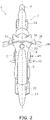
- FIG. 1 is a side view of the straddled vehicle 1 according to the embodiment.
- FIG. 2 is a top view of the straddled vehicle 1.
- the straddled vehicle 1 includes a vehicle body frame 2, a steering device 3, a front wheel 4, a seat 5, an engine 6, a rear wheel 7, a swing arm 8, and a vehicle body cover 9.
- the front-rear, left-right directions mean the front-back, left-right directions as seen from a rider seated on the seat 5.
- the vehicle body frame 2 includes a head pipe 11, a first main frame 12, a second main frame 13, a first rear frame 14, and a second rear frame 15.
- the head pipe 11 extends forward and downward.
- the first main frame 12 is connected to the head pipe 11.
- the first main frame 12 extends from the head pipe 11 through behind the engine 6.
- the first main frame 12 extends rearward and downward.
- connection is not limited to a plurality of separate parts being connected to each other by welding, bonding, or fixing means such as bolts, and a plurality of parts included in an integral portion being continuously connected each other.
- the first rear frame 14 is connected to the first main frame 12.
- the first rear frame 14 extends rearward and upward from the first main frame 12.
- the second rear frame 15 is connected to the first main frame 12.
- the second rear frame 15 is disposed below the first rear frame 14 with regard to up-down direction of the straddled vehicle 1.
- the second rear frame 15 extends rearward and upward.
- the steering device 3 is rotatably supported by the head pipe 11.
- the steering device 3 is configured to be steered by the rider.
- the steering device 3 includes a front fork 16 and a handle member 17.
- the front fork 16 rotatably supports the front wheel 4.
- the front fork 16 is rotatably supported by the head pipe 11.
- the handle member 17 is connected to the front fork 16.
- the handle member 17 includes a grip 18.
- the grip 18 extends in the left-right direction of the vehicle. The grip 18 is gripped by the rider.
- the seat 5 is disposed behind the head pipe 11.
- the seat 5 is supported by the vehicle body frame 2.
- the engine 6 is disposed below the seat 5.
- the engine 6 is supported by the first main frame 12 and the second main frame 13.
- the engine 6 is disposed between the first main frame 12 and the second main frame 13.
- a footrest 19 is disposed below the seat 5. The footrest 19 projects laterally from the first main frame 12.
- the engine 6 generates a driving force for rotating the rear wheel 7.
- the rear wheel 7 is disposed behind the engine 6.
- the rear wheel 7 are connected to the first main frame 12 via the swing arm 8.
- the swing arm 8 is swingably supported by the first main frame 12.
- the rear wheel 7 is rotatably supported by the swing arm 8.
- the vehicle body cover 9 is disposed on the outside of the first main frame 12 in the vehicle left-right direction.
- the vehicle body cover 9 covers the first main frame 12 from the side. As seen in a vehicle side view, the vehicle body cover 9 overlaps with at least a portion of the first main frame 12. As seen in the vehicle side view, at least a portion of the vehicle body cover 9 is located above the engine 6.
- the straddled vehicle 1 includes a muffler 21 and an exhaust pipe 22.
- the muffler 21 silences the exhaust gas from the engine 6 and discharges the exhaust gas.
- the muffler 21 extends rearward and upward. At least a portion of the muffler 21 is disposed higher than the rear wheel 7 with regard to up-down direction of the straddled vehicle 1.
- the rear end of the muffler 21 is located higher than the top of the rear wheel 7 with regard to up-down direction of the straddled vehicle 1.
- a portion of the muffler 21 may be located lower than the top of the rear wheel 7.
- a portion of the muffler 21 may overlap with the rear wheel 7 as seen in the vehicle side view.
- the exhaust pipe 22 is connected to the engine 6 and the muffler 21.
- the exhaust pipe 22 extends from the engine 6 toward the muffler 21.
- the exhaust gas from the engine 6 flows to the muffler 21 through the exhaust pipe 22.
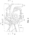
- FIG. 3 is an enlarged side view of the engine 6 and its surroundings. As illustrated in FIG. 3 , the exhaust pipe 22 extends forward from the engine 6 and is bent rearward in front of the engine 6. The exhaust pipe 22 extends rearward through the outside of the engine 6 in the vehicle left-right direction.
- the exhaust pipe 22 intersects the first main frame 12 as seen in the vehicle side view.
- the exhaust pipe 22 overlaps with the first main frame 12 as seen in the vehicle side view.
- the exhaust pipe 22 intersects the first main frame 12 behind the engine 6 as seen in the vehicle side view.
- the exhaust pipe 22 passes through the inside of the vehicle body frame 2 in the vehicle left-right direction and extends toward the muffler 21.
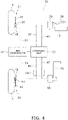
- FIG. 4 is a schematic view showing a configuration of a brake system 30 of the straddled vehicle 1.
- the brake system 30 includes a front brake 31, a rear brake 32, a hydraulic unit 33, and an ABS (Anti-lock Braking System) controller 34.
- the front brake 31 brakes the front wheel 4.
- the rear brake 32 brakes the rear wheel 7.
- the hydraulic unit 33 and the rear brake 32 are disposed on the same side in the left-right direction with respect to the center line C1 of the straddled vehicle 1 extending in the vehicle front-rear direction.
- the hydraulic unit 33 and the rear brake 32 are disposed on the right side with respect to the center line C1 of the straddled vehicle 1.
- the front brake 31 and the rear brake 32 are hydraulic disc brakes.
- the front brake 31 includes a front brake disc 35 and a front brake caliper 36.
- the front brake disc 35 is connected to the front wheel 4.
- the front brake caliper 36 brakes the front wheel 4 by sandwiching the front brake disc 35 by hydraulic pressure.
- the front brake caliper 36 is connected to the hydraulic unit 33 via the front brake pipe 37.
- the brake system 30 includes a brake lever 38 and a front master cylinder 39.
- the brake lever 38 is an example of a front brake operating member for operating the front brake 31.
- the brake lever 38 is disposed in front of the grip 18.
- the front master cylinder 39 is connected to the brake lever 38.
- the front master cylinder 39 generates brake hydraulic pressure according to the operation of the brake lever 38.
- the front master cylinder 39 is connected to the hydraulic unit 33 via the front connecting pipe 41.
- the front master cylinder 39 When the brake lever 38 is operated, the front master cylinder 39 generates the brake hydraulic pressure corresponding to the operation of the brake lever 38. This brake hydraulic pressure is supplied to the hydraulic unit 33 through the front connecting pipe 41. The hydraulic unit 33 operates the front brake 31 by supplying the brake hydraulic pressure to the front brake 31 through the front brake pipe 37.
- the rear brake 32 includes a rear brake disc 42 and a rear brake caliper 43.
- the rear brake disc 42 is connected to the rear wheel 7.
- the rear brake caliper 43 brakes the rear wheel 7 by sandwiching the rear brake disc 42 by hydraulic pressure.
- the rear brake caliper 43 is connected to the hydraulic unit 33 via the rear brake pipe 44.
- the brake system 30 includes a brake pedal 45 and a rear master cylinder 46.
- the brake pedal 45 is an example of a rear brake operating member for operating the rear brake 32.
- the brake pedal 45 is disposed below the footrest 19.
- the rear master cylinder 46 is connected to the brake pedal 45.
- the rear master cylinder 46 generates brake hydraulic pressure according to the operation of the brake pedal 45.
- the rear master cylinder 46 is connected to the hydraulic unit 33 via the rear connecting pipe 47.
- the rear master cylinder 46 When the brake pedal 45 is operated, the rear master cylinder 46 generates the brake hydraulic pressure corresponding to the operation of the brake pedal 45. This brake hydraulic pressure is supplied to the hydraulic unit 33 though the rear connecting pipe 47. The hydraulic unit 33 operates the rear brake 32 by supplying the brake hydraulic pressure to the rear brake 32 though the rear brake pipe 44.
- the hydraulic unit 33 is disposed inside the vehicle body cover 9, for example.
- the hydraulic unit 33 is disposed higher than the exhaust pipe 22 with regard to up-down direction of the straddled vehicle 1. However, the hydraulic unit 33 may be disposed at a place other than the inside of the vehicle body cover 9.
- the hydraulic unit 33 is disposed between the brake lever 38 and the brake pedal 45 in a vehicle plan view.
- the hydraulic unit 33 includes an electric motor, a pump, a solenoid valve and the like.
- the hydraulic unit 33 controls the brake hydraulic pressure of the front brake 31 and the rear brake 32 in response to a signal from the ABS controller 34.
- the brake system 30 includes a front wheel sensor 48 and a rear wheel sensor 49.
- the front wheel sensor 48 detects the rotation speed of the front wheel 4 and outputs a signal indicating the rotation speed of the front wheel 4.
- the rear wheel sensor 49 detects the rotation speed of the rear wheel 7 and outputs a signal indicating the rotation speed of the rear wheel 7.
- the ABS controller 34 is connected to the front wheel sensor 48 via a communication line 51.
- the ABS controller 34 receives the signal from the front wheel sensor 48 indicating the rotation speed of the front wheel 4.
- the ABS controller 34 is connected to the rear wheel sensor 49 via a communication line 52.
- the ABS controller 34 receives the signal from the rear wheel sensor 49 indicating the rotation speed of the rear wheel 7.
- the ABS controller 34 monitors the rotation speed of the front wheel 4 and the rotation speed of the rear wheel 7, and controls the brake hydraulic pressure from the hydraulic unit 33 so that the front wheel 4 and the rear wheel 7 do not lock.
- the rear brake pipe 44 described above extends from the hydraulic unit 33 to the rear brake 32. As illustrated in FIG. 3 , at least a portion of the rear brake pipe 44 is disposed along the first main frame 12.
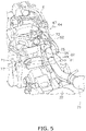
- FIG. 5 is a perspective view showing the rear brake pipe 44 and its surroundings.
- FIG. 6 is a top view schematically showing the rear brake pipe 44, the exhaust pipe 22, and the first main frame 12. In addition, in FIG. 6 , the first main frame 12 is illustrated in the VI-VI cross section in FIG. 3 .
- the rear brake pipe 44 includes a first bent portion 61, a first front portion 62, a first rear portion 63, and a brake hose 64.
- the first bent portion 61, the first front portion 62, and the first rear portion 63 are disposed along the first main frame 12.
- the first bent portion 61, the first front portion 62, and the first rear portion 63 are made of metal pipes.
- the first bent portion 61 overlaps with the exhaust pipe 22 as seen in the vehicle side view.
- the hydraulic unit 33 is disposed forward of the first bent portion 61.
- the first front portion 62 is connected to the first bent portion 61.
- the first front portion 62 is located forward of the first bent portion 61.
- the first front portion 62 is located higher than the exhaust pipe 22.
- the first rear portion 63 is connected to the first bent portion 61.
- the first rear portion 63 is located rearward of the first bent portion 61.
- the first rear portion 63 is located lower than the exhaust pipe 22 with regard to up-down direction of the straddled vehicle 1.
- the first front portion 62 and the first rear portion 63 are aligned in a straight line as seen in the vehicle top view.
- the first rear portion 63 is connected to the brake hose 64 via the connector 53.
- the brake hose 64 is made of a flexible material such as rubber.
- the brake hose 64 is connected to the rear brake 32.
- the first bent portion 61 includes a linear shape as seen in the vehicle side view. As illustrated in FIG. 6 , the first bent portion 61 is disposed inside the exhaust pipe 22 in the vehicle left-right direction. In the vehicle left-right direction, the gap G1 between the exhaust pipe 22 and the first bent portion 61 is larger than the gap G2 between the vehicle body frame 2 and the exhaust pipe 22.
- "120" indicates a portion of the first main frame 12 that overlaps with the exhaust pipe 22 as seen in the vehicle side view (hereinafter, referred to as "overlapping portion").
- the overlapping portion 120 is disposed outside the exhaust pipe 22 in the vehicle left-right direction. That is, the exhaust pipe 22 is disposed between the first bent portion 61 and the overlapping portion 120 in the vehicle left-right direction.
- the first bent portion 61 includes a first upper portion 65, a first lower portion 66, and a first side portion 67.
- the first upper portion 65 is disposed above the exhaust pipe 22 with regard to up-down direction of the straddled vehicle 1. As seen in the vehicle top view, the first upper portion 65 overlaps with the exhaust pipe 22. The first upper portion 65 extends linearly in the vehicle left-right direction. The first upper portion 65 is bent perpendicular to the first front portion 62. The first lower portion 66 is disposed below the exhaust pipe 22. The first lower portion 66 overlaps with the exhaust pipe 22 as seen in the vehicle top view. The first lower portion 66 extends linearly in the vehicle left-right direction. The first lower portion 66 is bent perpendicular to the first rear portion 63.
- the first side portion 67 is disposed inside the exhaust pipe 22 in the vehicle left-right direction.
- the first side portion 67 overlaps with the exhaust pipe 22 as seen in the vehicle side view.
- the first side portion 67 includes a first straight portion 68 and a second straight portion 69.
- the first side portion 67 has a shape bent between the first straight portion 68 and the second straight portion 69 as seen in the vehicle top view.
- the first straight portion 68 is connected to the first upper portion 65 and the second straight portion 69.
- the second straight portion 69 is connected to the first straight portion 68 and the first lower portion 66.
- the second straight portion 69 extends in parallel with the first front portion 62 and the first rear portion 63 as seen in the vehicle top view.
- the first straight portion 68 is inclined with respect to the second straight portion 69.
- the gap G1 between the exhaust pipe 22 and the first bent portion 61 described above is a gap between the second straight portion 69 and the exhaust pipe 22 in the vehicle left-right direction.
- the rear connecting pipe 47 described above extends from the hydraulic unit 33 to the rear master cylinder 46 via the connector 53.
- the rear master cylinder 46 is omitted in FIG. 3 for ease of understanding, the rear master cylinder 46 is disposed inside the first main frame 12 in the vicinity of, for example, the brake pedal 45.
- the rear connecting pipe 47 includes a second bent portion 71, a second front portion 72, and a second rear portion 73.
- the second bent portion 71, the second front portion 72, and the second rear portion 73 are made of metal pipes.
- the second bent portion 71, the second front portion 72, and the second rear portion 73 have the same shapes as the first bent portion 61, the first front portion 62, and the first rear portion 63 of the rear brake pipe 44, respectively.
- the second bent portion 71 is disposed in parallel with the first bent portion 61.
- the second bent portion 71 is connected to the first bent portion 61 by clips 80 to 87.
- the second front portion 72 is disposed in parallel with the first front portion 62.
- the second rear portion 73 is disposed in parallel with the first rear portion 63.
- the second bent portion 71 includes a second upper portion 75, a second lower portion 76, and a second side portion 77.
- the second upper portion 75, the second lower portion 76, and the second side portion 77 have the same shapes as the first upper portion 65, the first lower portion 66, and the first side portion 67, respectively.
- the second upper portion 75 is disposed parallel to the first upper portion 65.
- the second lower portion 76 is disposed in parallel with the first lower portion 66.
- the second side portion 77 is disposed in parallel with the first side portion 67.
- the rear brake pipe 44 is disposed so as to avoid the exhaust pipe 22 at the first bent portion 61.
- the brake oil in the rear brake pipe 44 is suppressed from being affected by heat of the exhaust pipe 22 while avoiding interference between the exhaust pipe 22 and the rear brake pipe 44.
- the length of the rear brake pipe 44 can be shortened while avoiding interference with the exhaust pipe 22.
- the first bent portion 61 is disposed inside the exhaust pipe 22 in the vehicle left-right direction. If the first bent portion 61 is disposed outside the exhaust pipe 22 in the vehicle left-right direction, the arrangement of the first bent portion 61 is restricted by the first main frame 12 disposed outside the exhaust pipe 22. However, since the first bent portion 61 is disposed inside the exhaust pipe 22, the first bent portion 61 can be disposed without being restricted by the first main frame 12. As a result, it becomes easy to provide a large distance between the exhaust pipe 22 and the first bent portion 61. Therefore, the brake oil in the rear brake pipe 44 is further suppressed from being affected by the heat of the exhaust pipe 22.
- the second bent portion 71 of the rear connecting pipe 47 has the same shape as the first bent portion 61 of the rear brake pipe 44. Therefore, the same effect as that of the rear brake pipe 44 described above can be obtained for the rear connecting pipe 47.
- the configuration of the straddled vehicle 1 is not limited to that of the above embodiment, and may be changed.
- the shape of the first main frame 12 or the second main frame 13 may be changed.
- the shape of the first bent portion 61 is not limited to that of the above embodiment, and may be changed.
- the first straight portion 68 and the second straight portion 69 may be aligned on a straight line as seen in the vehicle top view. That is, the first side portion 67 may have a linear shape as seen in the vehicle top view.
- the first front portion 62 and the first rear portion 63 may be disposed so as to be offset from the straight line as seen in the vehicle top view.
- the angle between the first upper portion 65 of the first bent portion 61 and the first front portion 62 is not limited to vertical.
- the angle between the first upper portion 65 and the first front portion 62 of the first bent portion 61 may be larger than vertical or smaller than vertical.
- the angle between the first lower portion 66 of the first bent portion 61 and the first rear portion 63 is not limited to vertical.
- the angle between the first lower portion 66 and the first rear portion 63 of the first bent portion 61 may be larger than vertical or smaller than vertical.
- the arrangement of the hydraulic unit 33 and the rear brake 32 is not limited to that of the above embodiment, and may be changed.
- the hydraulic unit 33 and the rear brake 32 may be disposed on the left side with respect to the center line C1 of the straddled vehicle 1.
- the hydraulic unit 33 and the rear brake 32 may be disposed on different sides in the left-right direction with respect to the center line C1 of the straddled vehicle 1.
- the hydraulic unit 33 may be disposed on the left side of the center line C1 of the straddled vehicle 1
- the rear brake 32 may be disposed on the right side of the center line C1 of the straddled vehicle 1.
- the hydraulic unit 33 may be disposed on the right side of the center line C1 of the straddled vehicle 1
- the rear brake 32 may be disposed on the left side of the center line C1 of the straddled vehicle 1.
Landscapes
- Engineering & Computer Science (AREA)
- Transportation (AREA)
- Mechanical Engineering (AREA)
- Physics & Mathematics (AREA)
- Electromagnetism (AREA)
- Fluid Mechanics (AREA)
- Valves And Accessory Devices For Braking Systems (AREA)
- Motorcycle And Bicycle Frame (AREA)
- Exhaust Silencers (AREA)
Applications Claiming Priority (1)
| Application Number | Priority Date | Filing Date | Title |
|---|---|---|---|
| JP2021073163A JP2022167396A (ja) | 2021-04-23 | 2021-04-23 | 鞍乗型車両 |
Publications (2)
| Publication Number | Publication Date |
|---|---|
| EP4079587A1 true EP4079587A1 (fr) | 2022-10-26 |
| EP4079587B1 EP4079587B1 (fr) | 2023-06-14 |
Family
ID=78528714
Family Applications (1)
| Application Number | Title | Priority Date | Filing Date |
|---|---|---|---|
| EP21206454.7A Active EP4079587B1 (fr) | 2021-04-23 | 2021-11-04 | Véhicule à enfourcher |
Country Status (2)
| Country | Link |
|---|---|
| EP (1) | EP4079587B1 (fr) |
| JP (1) | JP2022167396A (fr) |
Citations (4)
| Publication number | Priority date | Publication date | Assignee | Title |
|---|---|---|---|---|
| US20050134114A1 (en) * | 2003-12-19 | 2005-06-23 | Suzuki Kabushiki Kaisha | Motorcycle with antilock brake system |
| US20070200430A1 (en) * | 2006-02-27 | 2007-08-30 | Honda Motor Co., Ltd. | Brake system of motorcycle |
| WO2011099209A1 (fr) * | 2010-02-09 | 2011-08-18 | スズキ株式会社 | Véhicule deux-roues motorisé du type scooter |
| JP2017030394A (ja) | 2015-07-29 | 2017-02-09 | 本田技研工業株式会社 | 鞍乗型車両 |
-
2021
- 2021-04-23 JP JP2021073163A patent/JP2022167396A/ja active Pending
- 2021-11-04 EP EP21206454.7A patent/EP4079587B1/fr active Active
Patent Citations (4)
| Publication number | Priority date | Publication date | Assignee | Title |
|---|---|---|---|---|
| US20050134114A1 (en) * | 2003-12-19 | 2005-06-23 | Suzuki Kabushiki Kaisha | Motorcycle with antilock brake system |
| US20070200430A1 (en) * | 2006-02-27 | 2007-08-30 | Honda Motor Co., Ltd. | Brake system of motorcycle |
| WO2011099209A1 (fr) * | 2010-02-09 | 2011-08-18 | スズキ株式会社 | Véhicule deux-roues motorisé du type scooter |
| JP2017030394A (ja) | 2015-07-29 | 2017-02-09 | 本田技研工業株式会社 | 鞍乗型車両 |
Also Published As
| Publication number | Publication date |
|---|---|
| JP2022167396A (ja) | 2022-11-04 |
| EP4079587B1 (fr) | 2023-06-14 |
Similar Documents
| Publication | Publication Date | Title |
|---|---|---|
| US8186470B2 (en) | Motorcycle | |
| KR101260588B1 (ko) | 안장형 차량의 제동 장치 | |
| JP5109207B2 (ja) | 自動二輪車 | |
| JP5751989B2 (ja) | 自動二輪車 | |
| JP4354784B2 (ja) | 自動二輪車の制動力調整装置 | |
| EP3715234B1 (fr) | Véhicule de type à enfourcher | |
| JP2013220661A (ja) | 鞍乗型車両 | |
| EP4079587B1 (fr) | Véhicule à enfourcher | |
| JP5037463B2 (ja) | 圧力センサ支持構造を備えた自動二輪車 | |
| JP2009090887A (ja) | 鞍乗型車両 | |
| JP2015085844A (ja) | 鞍乗型車両 | |
| EP3437966A1 (fr) | Véhicule du type chevauché | |
| CN111032502B (zh) | 鞍乘型车辆的前部结构 | |
| JP3157690U (ja) | 鞍乗型車両 | |
| JP2020164101A (ja) | 鞍乗り型車両 | |
| JP7305817B1 (ja) | 鞍乗り型車両 | |
| CN111148691B (zh) | 跨骑型车辆的制动配管结构 | |
| WO2023053224A1 (fr) | Véhicule à selle | |
| JP6855585B2 (ja) | 鞍乗り型車両の前部構造 | |
| JP7373518B2 (ja) | 鞍乗り型車両のブレーキ装置 | |
| EP4180309A1 (fr) | Véhicule de type à selle | |
| JP3851500B2 (ja) | 車両用ブレーキ装置 | |
| WO2020031455A1 (fr) | Véhicule de type à selle | |
| JP2024066701A (ja) | Absモジュレーター配管配置構造 |
Legal Events
| Date | Code | Title | Description |
|---|---|---|---|
| PUAI | Public reference made under article 153(3) epc to a published international application that has entered the european phase |
Free format text: ORIGINAL CODE: 0009012 |
|
| STAA | Information on the status of an ep patent application or granted ep patent |
Free format text: STATUS: REQUEST FOR EXAMINATION WAS MADE |
|
| 17P | Request for examination filed |
Effective date: 20211104 |
|
| AK | Designated contracting states |
Kind code of ref document: A1 Designated state(s): AL AT BE BG CH CY CZ DE DK EE ES FI FR GB GR HR HU IE IS IT LI LT LU LV MC MK MT NL NO PL PT RO RS SE SI SK SM TR |
|
| GRAP | Despatch of communication of intention to grant a patent |
Free format text: ORIGINAL CODE: EPIDOSNIGR1 |
|
| STAA | Information on the status of an ep patent application or granted ep patent |
Free format text: STATUS: GRANT OF PATENT IS INTENDED |
|
| INTG | Intention to grant announced |
Effective date: 20230213 |
|
| GRAS | Grant fee paid |
Free format text: ORIGINAL CODE: EPIDOSNIGR3 |
|
| GRAA | (expected) grant |
Free format text: ORIGINAL CODE: 0009210 |
|
| STAA | Information on the status of an ep patent application or granted ep patent |
Free format text: STATUS: THE PATENT HAS BEEN GRANTED |
|
| AK | Designated contracting states |
Kind code of ref document: B1 Designated state(s): AL AT BE BG CH CY CZ DE DK EE ES FI FR GB GR HR HU IE IS IT LI LT LU LV MC MK MT NL NO PL PT RO RS SE SI SK SM TR |
|
| REG | Reference to a national code |
Ref country code: CH Ref legal event code: EP |
|
| REG | Reference to a national code |
Ref country code: DE Ref legal event code: R096 Ref document number: 602021002933 Country of ref document: DE |
|
| P01 | Opt-out of the competence of the unified patent court (upc) registered |
Effective date: 20230527 |
|
| REG | Reference to a national code |
Ref country code: AT Ref legal event code: REF Ref document number: 1579033 Country of ref document: AT Kind code of ref document: T Effective date: 20230715 |
|
| REG | Reference to a national code |
Ref country code: LT Ref legal event code: MG9D |
|
| REG | Reference to a national code |
Ref country code: NL Ref legal event code: MP Effective date: 20230614 |
|
| PG25 | Lapsed in a contracting state [announced via postgrant information from national office to epo] |
Ref country code: SE Free format text: LAPSE BECAUSE OF FAILURE TO SUBMIT A TRANSLATION OF THE DESCRIPTION OR TO PAY THE FEE WITHIN THE PRESCRIBED TIME-LIMIT Effective date: 20230614 Ref country code: NO Free format text: LAPSE BECAUSE OF FAILURE TO SUBMIT A TRANSLATION OF THE DESCRIPTION OR TO PAY THE FEE WITHIN THE PRESCRIBED TIME-LIMIT Effective date: 20230914 Ref country code: ES Free format text: LAPSE BECAUSE OF FAILURE TO SUBMIT A TRANSLATION OF THE DESCRIPTION OR TO PAY THE FEE WITHIN THE PRESCRIBED TIME-LIMIT Effective date: 20230614 |
|
| REG | Reference to a national code |
Ref country code: AT Ref legal event code: MK05 Ref document number: 1579033 Country of ref document: AT Kind code of ref document: T Effective date: 20230614 |
|
| PG25 | Lapsed in a contracting state [announced via postgrant information from national office to epo] |
Ref country code: RS Free format text: LAPSE BECAUSE OF FAILURE TO SUBMIT A TRANSLATION OF THE DESCRIPTION OR TO PAY THE FEE WITHIN THE PRESCRIBED TIME-LIMIT Effective date: 20230614 Ref country code: NL Free format text: LAPSE BECAUSE OF FAILURE TO SUBMIT A TRANSLATION OF THE DESCRIPTION OR TO PAY THE FEE WITHIN THE PRESCRIBED TIME-LIMIT Effective date: 20230614 Ref country code: LV Free format text: LAPSE BECAUSE OF FAILURE TO SUBMIT A TRANSLATION OF THE DESCRIPTION OR TO PAY THE FEE WITHIN THE PRESCRIBED TIME-LIMIT Effective date: 20230614 Ref country code: LT Free format text: LAPSE BECAUSE OF FAILURE TO SUBMIT A TRANSLATION OF THE DESCRIPTION OR TO PAY THE FEE WITHIN THE PRESCRIBED TIME-LIMIT Effective date: 20230614 Ref country code: HR Free format text: LAPSE BECAUSE OF FAILURE TO SUBMIT A TRANSLATION OF THE DESCRIPTION OR TO PAY THE FEE WITHIN THE PRESCRIBED TIME-LIMIT Effective date: 20230614 Ref country code: GR Free format text: LAPSE BECAUSE OF FAILURE TO SUBMIT A TRANSLATION OF THE DESCRIPTION OR TO PAY THE FEE WITHIN THE PRESCRIBED TIME-LIMIT Effective date: 20230915 |
|
| PG25 | Lapsed in a contracting state [announced via postgrant information from national office to epo] |
Ref country code: FI Free format text: LAPSE BECAUSE OF FAILURE TO SUBMIT A TRANSLATION OF THE DESCRIPTION OR TO PAY THE FEE WITHIN THE PRESCRIBED TIME-LIMIT Effective date: 20230614 |
|
| PG25 | Lapsed in a contracting state [announced via postgrant information from national office to epo] |
Ref country code: SK Free format text: LAPSE BECAUSE OF FAILURE TO SUBMIT A TRANSLATION OF THE DESCRIPTION OR TO PAY THE FEE WITHIN THE PRESCRIBED TIME-LIMIT Effective date: 20230614 |
|
| PG25 | Lapsed in a contracting state [announced via postgrant information from national office to epo] |
Ref country code: IS Free format text: LAPSE BECAUSE OF FAILURE TO SUBMIT A TRANSLATION OF THE DESCRIPTION OR TO PAY THE FEE WITHIN THE PRESCRIBED TIME-LIMIT Effective date: 20231014 |
|
| PG25 | Lapsed in a contracting state [announced via postgrant information from national office to epo] |
Ref country code: SM Free format text: LAPSE BECAUSE OF FAILURE TO SUBMIT A TRANSLATION OF THE DESCRIPTION OR TO PAY THE FEE WITHIN THE PRESCRIBED TIME-LIMIT Effective date: 20230614 Ref country code: SK Free format text: LAPSE BECAUSE OF FAILURE TO SUBMIT A TRANSLATION OF THE DESCRIPTION OR TO PAY THE FEE WITHIN THE PRESCRIBED TIME-LIMIT Effective date: 20230614 Ref country code: RO Free format text: LAPSE BECAUSE OF FAILURE TO SUBMIT A TRANSLATION OF THE DESCRIPTION OR TO PAY THE FEE WITHIN THE PRESCRIBED TIME-LIMIT Effective date: 20230614 Ref country code: PT Free format text: LAPSE BECAUSE OF FAILURE TO SUBMIT A TRANSLATION OF THE DESCRIPTION OR TO PAY THE FEE WITHIN THE PRESCRIBED TIME-LIMIT Effective date: 20231016 Ref country code: IS Free format text: LAPSE BECAUSE OF FAILURE TO SUBMIT A TRANSLATION OF THE DESCRIPTION OR TO PAY THE FEE WITHIN THE PRESCRIBED TIME-LIMIT Effective date: 20231014 Ref country code: EE Free format text: LAPSE BECAUSE OF FAILURE TO SUBMIT A TRANSLATION OF THE DESCRIPTION OR TO PAY THE FEE WITHIN THE PRESCRIBED TIME-LIMIT Effective date: 20230614 Ref country code: CZ Free format text: LAPSE BECAUSE OF FAILURE TO SUBMIT A TRANSLATION OF THE DESCRIPTION OR TO PAY THE FEE WITHIN THE PRESCRIBED TIME-LIMIT Effective date: 20230614 Ref country code: AT Free format text: LAPSE BECAUSE OF FAILURE TO SUBMIT A TRANSLATION OF THE DESCRIPTION OR TO PAY THE FEE WITHIN THE PRESCRIBED TIME-LIMIT Effective date: 20230614 |
|
| PGFP | Annual fee paid to national office [announced via postgrant information from national office to epo] |
Ref country code: IT Payment date: 20231130 Year of fee payment: 3 Ref country code: FR Payment date: 20231120 Year of fee payment: 3 Ref country code: DE Payment date: 20231121 Year of fee payment: 3 |
|
| PG25 | Lapsed in a contracting state [announced via postgrant information from national office to epo] |
Ref country code: PL Free format text: LAPSE BECAUSE OF FAILURE TO SUBMIT A TRANSLATION OF THE DESCRIPTION OR TO PAY THE FEE WITHIN THE PRESCRIBED TIME-LIMIT Effective date: 20230614 |
|
| REG | Reference to a national code |
Ref country code: DE Ref legal event code: R097 Ref document number: 602021002933 Country of ref document: DE |
|
| PLBE | No opposition filed within time limit |
Free format text: ORIGINAL CODE: 0009261 |
|
| STAA | Information on the status of an ep patent application or granted ep patent |
Free format text: STATUS: NO OPPOSITION FILED WITHIN TIME LIMIT |
|
| PG25 | Lapsed in a contracting state [announced via postgrant information from national office to epo] |
Ref country code: DK Free format text: LAPSE BECAUSE OF FAILURE TO SUBMIT A TRANSLATION OF THE DESCRIPTION OR TO PAY THE FEE WITHIN THE PRESCRIBED TIME-LIMIT Effective date: 20230614 |
|
| PG25 | Lapsed in a contracting state [announced via postgrant information from national office to epo] |
Ref country code: SI Free format text: LAPSE BECAUSE OF FAILURE TO SUBMIT A TRANSLATION OF THE DESCRIPTION OR TO PAY THE FEE WITHIN THE PRESCRIBED TIME-LIMIT Effective date: 20230614 |
|
| 26N | No opposition filed |
Effective date: 20240315 |