WO2011096195A1 - Photosensitive resin composition, method for producing structure, and liquid discharge head - Google Patents
Photosensitive resin composition, method for producing structure, and liquid discharge head Download PDFInfo
- Publication number
- WO2011096195A1 WO2011096195A1 PCT/JP2011/000549 JP2011000549W WO2011096195A1 WO 2011096195 A1 WO2011096195 A1 WO 2011096195A1 JP 2011000549 W JP2011000549 W JP 2011000549W WO 2011096195 A1 WO2011096195 A1 WO 2011096195A1
- Authority
- WO
- WIPO (PCT)
- Prior art keywords
- atom
- resin composition
- photosensitive resin
- satisfy
- component
- Prior art date
Links
- 239000011342 resin composition Substances 0.000 title claims abstract description 66
- 238000004519 manufacturing process Methods 0.000 title claims description 24
- 239000007788 liquid Substances 0.000 title claims description 18
- 239000002253 acid Substances 0.000 claims abstract description 24
- 150000001875 compounds Chemical class 0.000 claims abstract description 23
- 239000003795 chemical substances by application Substances 0.000 claims abstract description 15
- 125000002091 cationic group Chemical group 0.000 claims abstract description 11
- 125000000129 anionic group Chemical group 0.000 claims abstract description 10
- 150000003839 salts Chemical class 0.000 claims abstract description 7
- 125000004432 carbon atom Chemical group C* 0.000 claims description 21
- 125000004433 nitrogen atom Chemical group N* 0.000 claims description 21
- 239000000758 substrate Substances 0.000 claims description 21
- 229910052757 nitrogen Inorganic materials 0.000 claims description 20
- 238000000034 method Methods 0.000 claims description 19
- 125000000962 organic group Chemical group 0.000 claims description 13
- ZOXJGFHDIHLPTG-UHFFFAOYSA-N Boron Chemical group [B] ZOXJGFHDIHLPTG-UHFFFAOYSA-N 0.000 claims description 10
- 229910052787 antimony Inorganic materials 0.000 claims description 10
- WATWJIUSRGPENY-UHFFFAOYSA-N antimony atom Chemical group [Sb] WATWJIUSRGPENY-UHFFFAOYSA-N 0.000 claims description 10
- 229910052796 boron Inorganic materials 0.000 claims description 10
- 229910052799 carbon Inorganic materials 0.000 claims description 10
- 125000001183 hydrocarbyl group Chemical group 0.000 claims description 10
- 229910052698 phosphorus Inorganic materials 0.000 claims description 10
- 125000004430 oxygen atom Chemical group O* 0.000 claims description 9
- YRHRIQCWCFGUEQ-UHFFFAOYSA-N thioxanthen-9-one Chemical group C1=CC=C2C(=O)C3=CC=CC=C3SC2=C1 YRHRIQCWCFGUEQ-UHFFFAOYSA-N 0.000 claims description 8
- RZVHIXYEVGDQDX-UHFFFAOYSA-N 9,10-anthraquinone Chemical group C1=CC=C2C(=O)C3=CC=CC=C3C(=O)C2=C1 RZVHIXYEVGDQDX-UHFFFAOYSA-N 0.000 claims description 7
- 229910052731 fluorine Inorganic materials 0.000 claims description 6
- 125000001153 fluoro group Chemical group F* 0.000 claims description 6
- 125000004437 phosphorous atom Chemical group 0.000 claims description 6
- OAICVXFJPJFONN-UHFFFAOYSA-N Phosphorus Chemical group [P] OAICVXFJPJFONN-UHFFFAOYSA-N 0.000 claims description 5
- 239000011574 phosphorus Substances 0.000 claims description 5
- 238000010438 heat treatment Methods 0.000 claims description 4
- 125000001997 phenyl group Chemical group [H]C1=C([H])C([H])=C(*)C([H])=C1[H] 0.000 claims description 4
- 150000003384 small molecules Chemical class 0.000 claims description 4
- 150000001721 carbon Chemical group 0.000 claims 6
- 238000007493 shaping process Methods 0.000 description 13
- 239000004593 Epoxy Substances 0.000 description 9
- 150000007514 bases Chemical class 0.000 description 9
- 230000035945 sensitivity Effects 0.000 description 9
- 238000010521 absorption reaction Methods 0.000 description 6
- 239000000463 material Substances 0.000 description 6
- 239000000203 mixture Substances 0.000 description 6
- 229920000647 polyepoxide Polymers 0.000 description 6
- 230000008569 process Effects 0.000 description 6
- 239000002904 solvent Substances 0.000 description 6
- 239000000126 substance Substances 0.000 description 6
- 238000002835 absorbance Methods 0.000 description 5
- 230000000052 comparative effect Effects 0.000 description 5
- 239000004843 novolac epoxy resin Substances 0.000 description 5
- 229920005989 resin Polymers 0.000 description 5
- 239000011347 resin Substances 0.000 description 5
- 239000007787 solid Substances 0.000 description 5
- RWSOTUBLDIXVET-UHFFFAOYSA-N Dihydrogen sulfide Chemical class S RWSOTUBLDIXVET-UHFFFAOYSA-N 0.000 description 4
- ZRALSGWEFCBTJO-UHFFFAOYSA-N Guanidine Chemical compound NC(N)=N ZRALSGWEFCBTJO-UHFFFAOYSA-N 0.000 description 4
- GLUUGHFHXGJENI-UHFFFAOYSA-N Piperazine Chemical compound C1CNCCN1 GLUUGHFHXGJENI-UHFFFAOYSA-N 0.000 description 4
- KYQCOXFCLRTKLS-UHFFFAOYSA-N Pyrazine Chemical compound C1=CN=CC=N1 KYQCOXFCLRTKLS-UHFFFAOYSA-N 0.000 description 4
- 125000003277 amino group Chemical group 0.000 description 4
- IISBACLAFKSPIT-UHFFFAOYSA-N bisphenol A Chemical compound C=1C=C(O)C=CC=1C(C)(C)C1=CC=C(O)C=C1 IISBACLAFKSPIT-UHFFFAOYSA-N 0.000 description 4
- 238000013461 design Methods 0.000 description 4
- SWSQBOPZIKWTGO-UHFFFAOYSA-N dimethylaminoamidine Natural products CN(C)C(N)=N SWSQBOPZIKWTGO-UHFFFAOYSA-N 0.000 description 4
- 239000003822 epoxy resin Substances 0.000 description 4
- 239000004065 semiconductor Substances 0.000 description 4
- IDLHTECVNDEOIY-UHFFFAOYSA-N 2-pyridin-4-ylethanamine Chemical compound NCCC1=CC=NC=C1 IDLHTECVNDEOIY-UHFFFAOYSA-N 0.000 description 3
- 206010034972 Photosensitivity reaction Diseases 0.000 description 3
- RWRDLPDLKQPQOW-UHFFFAOYSA-N Pyrrolidine Chemical compound C1CCNC1 RWRDLPDLKQPQOW-UHFFFAOYSA-N 0.000 description 3
- 238000011161 development Methods 0.000 description 3
- 238000010586 diagram Methods 0.000 description 3
- RAXXELZNTBOGNW-UHFFFAOYSA-N imidazole Natural products C1=CNC=N1 RAXXELZNTBOGNW-UHFFFAOYSA-N 0.000 description 3
- 229910021421 monocrystalline silicon Inorganic materials 0.000 description 3
- 238000000059 patterning Methods 0.000 description 3
- 230000036211 photosensitivity Effects 0.000 description 3
- KJCVRFUGPWSIIH-UHFFFAOYSA-N 1-naphthol Chemical compound C1=CC=C2C(O)=CC=CC2=C1 KJCVRFUGPWSIIH-UHFFFAOYSA-N 0.000 description 2
- ICSNLGPSRYBMBD-UHFFFAOYSA-N 2-aminopyridine Chemical compound NC1=CC=CC=N1 ICSNLGPSRYBMBD-UHFFFAOYSA-N 0.000 description 2
- CUYKNJBYIJFRCU-UHFFFAOYSA-N 3-aminopyridine Chemical compound NC1=CC=CN=C1 CUYKNJBYIJFRCU-UHFFFAOYSA-N 0.000 description 2
- VHYFNPMBLIVWCW-UHFFFAOYSA-N 4-Dimethylaminopyridine Chemical compound CN(C)C1=CC=NC=C1 VHYFNPMBLIVWCW-UHFFFAOYSA-N 0.000 description 2
- FVCSARBUZVPSQF-UHFFFAOYSA-N 5-(2,4-dioxooxolan-3-yl)-7-methyl-3a,4,5,7a-tetrahydro-2-benzofuran-1,3-dione Chemical compound C1C(C(OC2=O)=O)C2C(C)=CC1C1C(=O)COC1=O FVCSARBUZVPSQF-UHFFFAOYSA-N 0.000 description 2
- KDCGOANMDULRCW-UHFFFAOYSA-N 7H-purine Chemical compound N1=CNC2=NC=NC2=C1 KDCGOANMDULRCW-UHFFFAOYSA-N 0.000 description 2
- 239000002841 Lewis acid Substances 0.000 description 2
- NTIZESTWPVYFNL-UHFFFAOYSA-N Methyl isobutyl ketone Chemical compound CC(C)CC(C)=O NTIZESTWPVYFNL-UHFFFAOYSA-N 0.000 description 2
- UIHCLUNTQKBZGK-UHFFFAOYSA-N Methyl isobutyl ketone Natural products CCC(C)C(C)=O UIHCLUNTQKBZGK-UHFFFAOYSA-N 0.000 description 2
- YNAVUWVOSKDBBP-UHFFFAOYSA-N Morpholine Chemical compound C1COCCN1 YNAVUWVOSKDBBP-UHFFFAOYSA-N 0.000 description 2
- CHJJGSNFBQVOTG-UHFFFAOYSA-N N-methyl-guanidine Natural products CNC(N)=N CHJJGSNFBQVOTG-UHFFFAOYSA-N 0.000 description 2
- PCNDJXKNXGMECE-UHFFFAOYSA-N Phenazine Natural products C1=CC=CC2=NC3=CC=CC=C3N=C21 PCNDJXKNXGMECE-UHFFFAOYSA-N 0.000 description 2
- NQRYJNQNLNOLGT-UHFFFAOYSA-N Piperidine Chemical compound C1CCNCC1 NQRYJNQNLNOLGT-UHFFFAOYSA-N 0.000 description 2
- WTKZEGDFNFYCGP-UHFFFAOYSA-N Pyrazole Chemical compound C=1C=NNC=1 WTKZEGDFNFYCGP-UHFFFAOYSA-N 0.000 description 2
- JUJWROOIHBZHMG-UHFFFAOYSA-N Pyridine Chemical compound C1=CC=NC=C1 JUJWROOIHBZHMG-UHFFFAOYSA-N 0.000 description 2
- CZPWVGJYEJSRLH-UHFFFAOYSA-N Pyrimidine Chemical compound C1=CN=CN=C1 CZPWVGJYEJSRLH-UHFFFAOYSA-N 0.000 description 2
- XUIMIQQOPSSXEZ-UHFFFAOYSA-N Silicon Chemical compound [Si] XUIMIQQOPSSXEZ-UHFFFAOYSA-N 0.000 description 2
- 125000002723 alicyclic group Chemical group 0.000 description 2
- 125000003282 alkyl amino group Chemical group 0.000 description 2
- 125000000217 alkyl group Chemical group 0.000 description 2
- 125000003118 aryl group Chemical group 0.000 description 2
- 125000004429 atom Chemical group 0.000 description 2
- 229940106691 bisphenol a Drugs 0.000 description 2
- 238000010538 cationic polymerization reaction Methods 0.000 description 2
- 239000011248 coating agent Substances 0.000 description 2
- 238000000576 coating method Methods 0.000 description 2
- 239000000470 constituent Substances 0.000 description 2
- 239000013078 crystal Substances 0.000 description 2
- 125000004093 cyano group Chemical group *C#N 0.000 description 2
- 238000005530 etching Methods 0.000 description 2
- 238000011156 evaluation Methods 0.000 description 2
- 125000002887 hydroxy group Chemical group [H]O* 0.000 description 2
- 150000007517 lewis acids Chemical class 0.000 description 2
- 125000000449 nitro group Chemical group [O-][N+](*)=O 0.000 description 2
- QWVGKYWNOKOFNN-UHFFFAOYSA-N o-cresol Chemical compound CC1=CC=CC=C1O QWVGKYWNOKOFNN-UHFFFAOYSA-N 0.000 description 2
- -1 oxetane compound Chemical class 0.000 description 2
- 238000000206 photolithography Methods 0.000 description 2
- 239000011295 pitch Substances 0.000 description 2
- 230000005855 radiation Effects 0.000 description 2
- 229910052710 silicon Inorganic materials 0.000 description 2
- 239000010703 silicon Substances 0.000 description 2
- 238000003860 storage Methods 0.000 description 2
- 125000001424 substituent group Chemical group 0.000 description 2
- WLOQLWBIJZDHET-UHFFFAOYSA-N triphenylsulfonium Chemical compound C1=CC=CC=C1[S+](C=1C=CC=CC=1)C1=CC=CC=C1 WLOQLWBIJZDHET-UHFFFAOYSA-N 0.000 description 2
- MPBCUCGKHDEUDD-UHFFFAOYSA-N (5-methylpyrazin-2-yl)methanamine Chemical compound CC1=CN=C(CN)C=N1 MPBCUCGKHDEUDD-UHFFFAOYSA-N 0.000 description 1
- KYVBNYUBXIEUFW-UHFFFAOYSA-N 1,1,3,3-tetramethylguanidine Chemical compound CN(C)C(=N)N(C)C KYVBNYUBXIEUFW-UHFFFAOYSA-N 0.000 description 1
- QDVBKXJMLILLLB-UHFFFAOYSA-N 1,4'-bipiperidine Chemical compound C1CCCCN1C1CCNCC1 QDVBKXJMLILLLB-UHFFFAOYSA-N 0.000 description 1
- BAXOFTOLAUCFNW-UHFFFAOYSA-N 1H-indazole Chemical compound C1=CC=C2C=NNC2=C1 BAXOFTOLAUCFNW-UHFFFAOYSA-N 0.000 description 1
- FTVFPPFZRRKJIH-UHFFFAOYSA-N 2,2,6,6-tetramethylpiperidin-4-amine Chemical compound CC1(C)CC(N)CC(C)(C)N1 FTVFPPFZRRKJIH-UHFFFAOYSA-N 0.000 description 1
- DHGUMNJVFYRSIG-UHFFFAOYSA-N 2,3,4,5-tetrahydropyridin-6-amine Chemical compound NC1=NCCCC1 DHGUMNJVFYRSIG-UHFFFAOYSA-N 0.000 description 1
- KEQTWHPMSVAFDA-UHFFFAOYSA-N 2,3-dihydro-1h-pyrazole Chemical compound C1NNC=C1 KEQTWHPMSVAFDA-UHFFFAOYSA-N 0.000 description 1
- WOXFMYVTSLAQMO-UHFFFAOYSA-N 2-Pyridinemethanamine Chemical compound NCC1=CC=CC=N1 WOXFMYVTSLAQMO-UHFFFAOYSA-N 0.000 description 1
- CJNRGSHEMCMUOE-UHFFFAOYSA-N 2-piperidin-1-ylethanamine Chemical compound NCCN1CCCCC1 CJNRGSHEMCMUOE-UHFFFAOYSA-N 0.000 description 1
- NAHHNSMHYCLMON-UHFFFAOYSA-N 2-pyridin-3-ylethanamine Chemical compound NCCC1=CC=CN=C1 NAHHNSMHYCLMON-UHFFFAOYSA-N 0.000 description 1
- WRXNJTBODVGDRY-UHFFFAOYSA-N 2-pyrrolidin-1-ylethanamine Chemical compound NCCN1CCCC1 WRXNJTBODVGDRY-UHFFFAOYSA-N 0.000 description 1
- RGDQRXPEZUNWHX-UHFFFAOYSA-N 3-methylpyridin-2-amine Chemical compound CC1=CC=CN=C1N RGDQRXPEZUNWHX-UHFFFAOYSA-N 0.000 description 1
- MCGBIXXDQFWVDW-UHFFFAOYSA-N 4,5-dihydro-1h-pyrazole Chemical compound C1CC=NN1 MCGBIXXDQFWVDW-UHFFFAOYSA-N 0.000 description 1
- DUFGYCAXVIUXIP-UHFFFAOYSA-N 4,6-dihydroxypyrimidine Chemical compound OC1=CC(O)=NC=N1 DUFGYCAXVIUXIP-UHFFFAOYSA-N 0.000 description 1
- NUKYPUAOHBNCPY-UHFFFAOYSA-N 4-aminopyridine Chemical compound NC1=CC=NC=C1 NUKYPUAOHBNCPY-UHFFFAOYSA-N 0.000 description 1
- ORLGLBZRQYOWNA-UHFFFAOYSA-N 4-methylpyridin-2-amine Chemical compound CC1=CC=NC(N)=C1 ORLGLBZRQYOWNA-UHFFFAOYSA-N 0.000 description 1
- FYTLHYRDGXRYEY-UHFFFAOYSA-N 5-Methyl-3-pyrazolamine Chemical compound CC=1C=C(N)NN=1 FYTLHYRDGXRYEY-UHFFFAOYSA-N 0.000 description 1
- WQUNBEPKWJLYJD-UHFFFAOYSA-N 5-methyl-2-(4-methylphenyl)pyrazol-3-amine Chemical compound N1=C(C)C=C(N)N1C1=CC=C(C)C=C1 WQUNBEPKWJLYJD-UHFFFAOYSA-N 0.000 description 1
- CMBSSVKZOPZBKW-UHFFFAOYSA-N 5-methylpyridin-2-amine Chemical compound CC1=CC=C(N)N=C1 CMBSSVKZOPZBKW-UHFFFAOYSA-N 0.000 description 1
- QUXLCYFNVNNRBE-UHFFFAOYSA-N 6-methylpyridin-2-amine Chemical compound CC1=CC=CC(N)=N1 QUXLCYFNVNNRBE-UHFFFAOYSA-N 0.000 description 1
- ZUUNHCQWPCGZDH-UHFFFAOYSA-N O=C(c1ccccc1)c(cc1)cc(Cl)c1Sc(cc1)ccc1[S+](c(cc1)ccc1F)c(cc1)ccc1F Chemical compound O=C(c1ccccc1)c(cc1)cc(Cl)c1Sc(cc1)ccc1[S+](c(cc1)ccc1F)c(cc1)ccc1F ZUUNHCQWPCGZDH-UHFFFAOYSA-N 0.000 description 1
- ISWSIDIOOBJBQZ-UHFFFAOYSA-N Phenol Chemical compound OC1=CC=CC=C1 ISWSIDIOOBJBQZ-UHFFFAOYSA-N 0.000 description 1
- VYPSYNLAJGMNEJ-UHFFFAOYSA-N Silicium dioxide Chemical compound O=[Si]=O VYPSYNLAJGMNEJ-UHFFFAOYSA-N 0.000 description 1
- LINDOXZENKYESA-UHFFFAOYSA-N TMG Natural products CNC(N)=NC LINDOXZENKYESA-UHFFFAOYSA-N 0.000 description 1
- 125000002252 acyl group Chemical group 0.000 description 1
- 239000003513 alkali Substances 0.000 description 1
- 125000003342 alkenyl group Chemical group 0.000 description 1
- 125000003545 alkoxy group Chemical group 0.000 description 1
- 125000000304 alkynyl group Chemical group 0.000 description 1
- 125000005336 allyloxy group Chemical group 0.000 description 1
- 125000004103 aminoalkyl group Chemical group 0.000 description 1
- 125000005001 aminoaryl group Chemical group 0.000 description 1
- IMUDHTPIFIBORV-UHFFFAOYSA-N aminoethylpiperazine Chemical compound NCCN1CCNCC1 IMUDHTPIFIBORV-UHFFFAOYSA-N 0.000 description 1
- 229950011175 aminopicoline Drugs 0.000 description 1
- 125000001769 aryl amino group Chemical group 0.000 description 1
- 125000004104 aryloxy group Chemical group 0.000 description 1
- 230000008901 benefit Effects 0.000 description 1
- 230000015572 biosynthetic process Effects 0.000 description 1
- 125000002915 carbonyl group Chemical group [*:2]C([*:1])=O 0.000 description 1
- 230000008859 change Effects 0.000 description 1
- 238000006243 chemical reaction Methods 0.000 description 1
- 238000000354 decomposition reaction Methods 0.000 description 1
- 238000009792 diffusion process Methods 0.000 description 1
- 238000007599 discharging Methods 0.000 description 1
- 238000001312 dry etching Methods 0.000 description 1
- 125000003700 epoxy group Chemical group 0.000 description 1
- RTZKZFJDLAIYFH-UHFFFAOYSA-N ether Substances CCOCC RTZKZFJDLAIYFH-UHFFFAOYSA-N 0.000 description 1
- 230000001747 exhibiting effect Effects 0.000 description 1
- 229960004979 fampridine Drugs 0.000 description 1
- 238000009472 formulation Methods 0.000 description 1
- 125000000524 functional group Chemical group 0.000 description 1
- 125000005843 halogen group Chemical group 0.000 description 1
- 125000000623 heterocyclic group Chemical group 0.000 description 1
- MBAKFIZHTUAVJN-UHFFFAOYSA-I hexafluoroantimony(1-);hydron Chemical compound F.F[Sb](F)(F)(F)F MBAKFIZHTUAVJN-UHFFFAOYSA-I 0.000 description 1
- 125000004435 hydrogen atom Chemical group [H]* 0.000 description 1
- MTNDZQHUAFNZQY-UHFFFAOYSA-N imidazoline Chemical compound C1CN=CN1 MTNDZQHUAFNZQY-UHFFFAOYSA-N 0.000 description 1
- 150000008040 ionic compounds Chemical class 0.000 description 1
- 238000005259 measurement Methods 0.000 description 1
- 239000012046 mixed solvent Substances 0.000 description 1
- 238000012986 modification Methods 0.000 description 1
- 230000004048 modification Effects 0.000 description 1
- MKQLBNJQQZRQJU-UHFFFAOYSA-N morpholin-4-amine Chemical compound NN1CCOCC1 MKQLBNJQQZRQJU-UHFFFAOYSA-N 0.000 description 1
- XRPITCBWOUOJTH-UHFFFAOYSA-N n,n-diethylpyridin-2-amine Chemical compound CCN(CC)C1=CC=CC=N1 XRPITCBWOUOJTH-UHFFFAOYSA-N 0.000 description 1
- PSHKMPUSSFXUIA-UHFFFAOYSA-N n,n-dimethylpyridin-2-amine Chemical compound CN(C)C1=CC=CC=N1 PSHKMPUSSFXUIA-UHFFFAOYSA-N 0.000 description 1
- RWIVICVCHVMHMU-UHFFFAOYSA-N n-aminoethylmorpholine Chemical compound NCCN1CCOCC1 RWIVICVCHVMHMU-UHFFFAOYSA-N 0.000 description 1
- 239000003960 organic solvent Substances 0.000 description 1
- 125000005740 oxycarbonyl group Chemical group [*:1]OC([*:2])=O 0.000 description 1
- JGTNAGYHADQMCM-UHFFFAOYSA-N perfluorobutanesulfonic acid Chemical compound OS(=O)(=O)C(F)(F)C(F)(F)C(F)(F)C(F)(F)F JGTNAGYHADQMCM-UHFFFAOYSA-N 0.000 description 1
- 239000003505 polymerization initiator Substances 0.000 description 1
- 238000012545 processing Methods 0.000 description 1
- RUOJZAUFBMNUDX-UHFFFAOYSA-N propylene carbonate Chemical compound CC1COC(=O)O1 RUOJZAUFBMNUDX-UHFFFAOYSA-N 0.000 description 1
- LLHKCFNBLRBOGN-UHFFFAOYSA-N propylene glycol methyl ether acetate Chemical compound COCC(C)OC(C)=O LLHKCFNBLRBOGN-UHFFFAOYSA-N 0.000 description 1
- DNXIASIHZYFFRO-UHFFFAOYSA-N pyrazoline Chemical compound C1CN=NC1 DNXIASIHZYFFRO-UHFFFAOYSA-N 0.000 description 1
- UMJSCPRVCHMLSP-UHFFFAOYSA-N pyridine Natural products COC1=CC=CN=C1 UMJSCPRVCHMLSP-UHFFFAOYSA-N 0.000 description 1
- YAAWASYJIRZXSZ-UHFFFAOYSA-N pyrimidine-2,4-diamine Chemical compound NC1=CC=NC(N)=N1 YAAWASYJIRZXSZ-UHFFFAOYSA-N 0.000 description 1
- IZBNHIWUATWXHK-UHFFFAOYSA-N pyrrolidin-2-amine Chemical compound NC1CCCN1 IZBNHIWUATWXHK-UHFFFAOYSA-N 0.000 description 1
- NGXSWUFDCSEIOO-UHFFFAOYSA-N pyrrolidin-3-amine Chemical compound NC1CCNC1 NGXSWUFDCSEIOO-UHFFFAOYSA-N 0.000 description 1
- 230000009467 reduction Effects 0.000 description 1
- 238000005488 sandblasting Methods 0.000 description 1
- 238000004528 spin coating Methods 0.000 description 1
- 125000000475 sulfinyl group Chemical group [*:2]S([*:1])=O 0.000 description 1
- 125000000472 sulfonyl group Chemical group *S(*)(=O)=O 0.000 description 1
- 150000005621 tetraalkylammonium salts Chemical class 0.000 description 1
- 125000002813 thiocarbonyl group Chemical group *C(*)=S 0.000 description 1
- 239000012953 triphenylsulfonium Substances 0.000 description 1
- 229920002554 vinyl polymer Polymers 0.000 description 1
Images


Classifications
-
- B—PERFORMING OPERATIONS; TRANSPORTING
- B41—PRINTING; LINING MACHINES; TYPEWRITERS; STAMPS
- B41J—TYPEWRITERS; SELECTIVE PRINTING MECHANISMS, i.e. MECHANISMS PRINTING OTHERWISE THAN FROM A FORME; CORRECTION OF TYPOGRAPHICAL ERRORS
- B41J2/00—Typewriters or selective printing mechanisms characterised by the printing or marking process for which they are designed
- B41J2/005—Typewriters or selective printing mechanisms characterised by the printing or marking process for which they are designed characterised by bringing liquid or particles selectively into contact with a printing material
- B41J2/01—Ink jet
- B41J2/135—Nozzles
- B41J2/16—Production of nozzles
- B41J2/1601—Production of bubble jet print heads
- B41J2/1603—Production of bubble jet print heads of the front shooter type
-
- B—PERFORMING OPERATIONS; TRANSPORTING
- B41—PRINTING; LINING MACHINES; TYPEWRITERS; STAMPS
- B41J—TYPEWRITERS; SELECTIVE PRINTING MECHANISMS, i.e. MECHANISMS PRINTING OTHERWISE THAN FROM A FORME; CORRECTION OF TYPOGRAPHICAL ERRORS
- B41J2/00—Typewriters or selective printing mechanisms characterised by the printing or marking process for which they are designed
- B41J2/005—Typewriters or selective printing mechanisms characterised by the printing or marking process for which they are designed characterised by bringing liquid or particles selectively into contact with a printing material
- B41J2/01—Ink jet
- B41J2/135—Nozzles
- B41J2/16—Production of nozzles
- B41J2/1621—Manufacturing processes
- B41J2/1637—Manufacturing processes molding
- B41J2/1639—Manufacturing processes molding sacrificial molding
-
- C—CHEMISTRY; METALLURGY
- C09—DYES; PAINTS; POLISHES; NATURAL RESINS; ADHESIVES; COMPOSITIONS NOT OTHERWISE PROVIDED FOR; APPLICATIONS OF MATERIALS NOT OTHERWISE PROVIDED FOR
- C09B—ORGANIC DYES OR CLOSELY-RELATED COMPOUNDS FOR PRODUCING DYES, e.g. PIGMENTS; MORDANTS; LAKES
- C09B69/00—Dyes not provided for by a single group of this subclass
- C09B69/001—Dyes containing an onium group attached to the dye skeleton via a bridge
- C09B69/004—Sulfonium group
-
- C—CHEMISTRY; METALLURGY
- C09—DYES; PAINTS; POLISHES; NATURAL RESINS; ADHESIVES; COMPOSITIONS NOT OTHERWISE PROVIDED FOR; APPLICATIONS OF MATERIALS NOT OTHERWISE PROVIDED FOR
- C09B—ORGANIC DYES OR CLOSELY-RELATED COMPOUNDS FOR PRODUCING DYES, e.g. PIGMENTS; MORDANTS; LAKES
- C09B69/00—Dyes not provided for by a single group of this subclass
- C09B69/10—Polymeric dyes; Reaction products of dyes with monomers or with macromolecular compounds
- C09B69/109—Polymeric dyes; Reaction products of dyes with monomers or with macromolecular compounds containing other specific dyes
-
- G—PHYSICS
- G03—PHOTOGRAPHY; CINEMATOGRAPHY; ANALOGOUS TECHNIQUES USING WAVES OTHER THAN OPTICAL WAVES; ELECTROGRAPHY; HOLOGRAPHY
- G03F—PHOTOMECHANICAL PRODUCTION OF TEXTURED OR PATTERNED SURFACES, e.g. FOR PRINTING, FOR PROCESSING OF SEMICONDUCTOR DEVICES; MATERIALS THEREFOR; ORIGINALS THEREFOR; APPARATUS SPECIALLY ADAPTED THEREFOR
- G03F7/00—Photomechanical, e.g. photolithographic, production of textured or patterned surfaces, e.g. printing surfaces; Materials therefor, e.g. comprising photoresists; Apparatus specially adapted therefor
- G03F7/004—Photosensitive materials
- G03F7/0045—Photosensitive materials with organic non-macromolecular light-sensitive compounds not otherwise provided for, e.g. dissolution inhibitors
-
- G—PHYSICS
- G03—PHOTOGRAPHY; CINEMATOGRAPHY; ANALOGOUS TECHNIQUES USING WAVES OTHER THAN OPTICAL WAVES; ELECTROGRAPHY; HOLOGRAPHY
- G03F—PHOTOMECHANICAL PRODUCTION OF TEXTURED OR PATTERNED SURFACES, e.g. FOR PRINTING, FOR PROCESSING OF SEMICONDUCTOR DEVICES; MATERIALS THEREFOR; ORIGINALS THEREFOR; APPARATUS SPECIALLY ADAPTED THEREFOR
- G03F7/00—Photomechanical, e.g. photolithographic, production of textured or patterned surfaces, e.g. printing surfaces; Materials therefor, e.g. comprising photoresists; Apparatus specially adapted therefor
- G03F7/004—Photosensitive materials
- G03F7/0046—Photosensitive materials with perfluoro compounds, e.g. for dry lithography
-
- G—PHYSICS
- G03—PHOTOGRAPHY; CINEMATOGRAPHY; ANALOGOUS TECHNIQUES USING WAVES OTHER THAN OPTICAL WAVES; ELECTROGRAPHY; HOLOGRAPHY
- G03F—PHOTOMECHANICAL PRODUCTION OF TEXTURED OR PATTERNED SURFACES, e.g. FOR PRINTING, FOR PROCESSING OF SEMICONDUCTOR DEVICES; MATERIALS THEREFOR; ORIGINALS THEREFOR; APPARATUS SPECIALLY ADAPTED THEREFOR
- G03F7/00—Photomechanical, e.g. photolithographic, production of textured or patterned surfaces, e.g. printing surfaces; Materials therefor, e.g. comprising photoresists; Apparatus specially adapted therefor
- G03F7/004—Photosensitive materials
- G03F7/038—Macromolecular compounds which are rendered insoluble or differentially wettable
-
- G—PHYSICS
- G03—PHOTOGRAPHY; CINEMATOGRAPHY; ANALOGOUS TECHNIQUES USING WAVES OTHER THAN OPTICAL WAVES; ELECTROGRAPHY; HOLOGRAPHY
- G03F—PHOTOMECHANICAL PRODUCTION OF TEXTURED OR PATTERNED SURFACES, e.g. FOR PRINTING, FOR PROCESSING OF SEMICONDUCTOR DEVICES; MATERIALS THEREFOR; ORIGINALS THEREFOR; APPARATUS SPECIALLY ADAPTED THEREFOR
- G03F7/00—Photomechanical, e.g. photolithographic, production of textured or patterned surfaces, e.g. printing surfaces; Materials therefor, e.g. comprising photoresists; Apparatus specially adapted therefor
- G03F7/26—Processing photosensitive materials; Apparatus therefor
- G03F7/40—Treatment after imagewise removal, e.g. baking
Definitions
- the present invention relates to a photosensitive resin composition, a method for producing a structure, and a liquid discharge head.
- a known micro-fabrication technique includes a photolithographic technique including subjecting a negative-type photosensitive resin to exposure to light and development to form a patterned structure.
- This technique is widely used in applications such as semiconductor integrated circuit production applications, semiconductor exposure mask production applications, and applications of the production of various microelectromechanical systems (MEMS).
- MEMS microelectromechanical systems
- the technique is used for the production of liquid discharge head nozzles. Steppers with i-line light sources are widely used as exposure devices.
- the production of more complicated and sophisticatedly-shaped structures has recently been demanded, and therefore, a negative-type photosensitive resin exhibiting high photosensitivity to light from a light source and high shaping accuracy has been demanded.
- Japanese Patent Application Laid-Open No. 2008-256980 discusses a photosensitive resin composition which contains a polyfunctional epoxy resin and a cationic polymerization initiator as an example of such a negative-type photosensitive resin.
- U.S. Patent No. 6,155,673 discusses an example of the structure of a liquid discharge device having nozzles in which bubbles produced by heating a heat resistor are allowed to communicate with outside air so that ink droplets can be discharged.
- the above composition does not have satisfactory properties in some cases for the reason below.
- a complicated structure such as a tapered discharge port for a liquid discharge device is formed using such a negative-type photosensitive resin composition and an i-line light source, an undesired shape such as a partially-rounded edge may be formed.
- the present invention is directed to a photosensitive resin composition with which a structure can be formed with high sensitivity and high shaping accuracy using i-line photolithography.
- a photosensitive resin composition including: (a) a compound polymerizable in the presence of an acid; and (b) a photoacid generating agent including an onium salt having a cationic part structure represented by formula (b1) below and an anionic part structure represented by formula (b2) below, wherein the component (b) absorbs 50% or more of the amount of 365 nm wavelength light absorbed by the photosensitive resin composition,
- R 1 to R 3 each independently represent an organic group of 1 to 30 carbon atoms;
- R 1 to R 3 represent structures containing at least two oxygen atoms and including at least one organic group selected from a thioxanthone skeleton, a 9,10-dialkoxyanthracene skeleton, or an anthraquinone skeleton;
- X is selected from a carbon atom, a nitrogen atom, a phosphorus atom, a boron atom, and an antimony atom;
- a photosensitive resin composition with which a structure can be formed with high sensitivity and high shaping accuracy using i-line photolithography.
- Fig. 1 is a diagram illustrating a mask for use in forming a model pattern in an exemplary embodiment of the present invention.
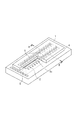
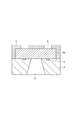
- Fig. 2 is a diagram illustrating an example of the structure of an inkjet recording head according to an exemplary embodiment of the present invention.
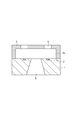
- Fig. 3 is a diagram illustrating a structure having a plurality of energy generation elements arranged at predetermined pitches on a substrate illustrated in Fig. 2.
- Fig. 4A is a cross-sectional view illustrating a process of manufacturing a liquid discharge head according to an exemplary embodiment of the present invention.
- Fig. 4B is a cross-sectional view illustrating the process of manufacturing the liquid discharge head according to an exemplary embodiment of the present invention.
- Fig. 1 is a diagram illustrating a mask for use in forming a model pattern in an exemplary embodiment of the present invention.
- Fig. 2 is a diagram illustrating an example of the structure of an inkjet recording head according to an exemplary embodiment of the present invention.
- FIG. 4C is a cross-sectional view illustrating the process of manufacturing the liquid discharge head according to an exemplary embodiment of the present invention.
- Fig. 4D is a cross-sectional view illustrating the process of manufacturing the liquid discharge head according to an exemplary embodiment of the present invention.
- Fig. 4E is a cross-sectional view illustrating the process of manufacturing the liquid discharge head according to an exemplary embodiment of the present invention.
- Fig. 4F is a cross-sectional view illustrating the process of manufacturing the liquid discharge head according to an exemplary embodiment of the present invention.
- Photosensitive Resin Composition The photosensitive resin composition according to an exemplary embodiment of the present invention is described in detail below.
- the photosensitive resin composition according to an exemplary embodiment of the present invention contains a compound (component (a)) polymerizable in the presence of an acid.
- the compound polymerizable in the presence of an acid may be any cationically polymerizable compound such as an epoxy compound, an oxetane compound, or a cationically polymerizable vinyl compound.
- an epoxy compound is preferred, and a polyfunctional epoxy compound having two or more epoxy groups is preferred.
- the number of functional groups in the polyfunctional epoxy compound is preferably five or more.
- polyfunctional epoxy compound examples include a polyfunctional alicyclic epoxy resin, a polyfunctional phenol novolac epoxy resin, a polyfunctional o-cresol novolac epoxy resin, a polyfunctional triphenyl-type novolac epoxy resin, and a polyfunctional bisphenol-A novolac epoxy resin.
- a polyfunctional bisphenol-A novolac epoxy resin or a polyfunctional alicyclic epoxy resin is preferred.
- Examples of a commercially available polyfunctional epoxy compound include Epicoat 157S70 (trade name) manufactured by Japan Epoxy Resins Co., Ltd., EPICLON N-865 (trade name) manufactured by DIC Corporation, and EHPE 3150 (trade name) manufactured by DAICEL CHEMICAL INDUSTRIES, LTD.
- the component (a) is preferably a solid at room temperature (24 degrees Celsius).
- the softening point of the component (a) is preferably, but not limited to, 50 to 180 degrees Celsius, more preferably 60 to 160 degrees Celsius.
- a single component (a) or two or more components (a) may be used alone or in combination.
- the content of the component (a) in the photosensitive resin composition is preferably from 60 to 99.9% by weight, more preferably from 80 to 99.9% by weight, even more preferably from 85 to 99.2% by weight, based on the total solids of the photosensitive resin composition.
- the photosensitive resin composition having a component (a) content in the above range can form a resist layer with high sensitivity and suitable hardness when applied to a supporting material.
- the photosensitive resin composition according to an exemplary embodiment of the present invention contains a photoacid generating agent (component (b)).
- the photoacid generating agent (component (b)) includes an onium salt having the ability to produce an acid upon exposure to i-line, specifically light at a wavelength of 365 nm, and having a cationic part structure represented by formula (b1) below and an anionic part structure represented by formula (b2) below.
- component (b) including an onium salt having a cationic part structure represented by formula (b1) and an anionic part structure represented by formula (b2) is illustrated below.
- R 1 to R 3 each independently represent an organic group of 1 to 30 carbon atoms, and R 1 to R 3 represent structures containing two or more oxygen atoms and including at least one organic group selected from a thioxanthone skeleton, a 9,10-dialkoxyanthracene skeleton, or an anthraquinone skeleton. Since the photoacid generating agent has the cationic part structure represented by formula (b1), the absorption wavelength shifts toward longer wavelengths, and the resulting photosensitive resin composition can have photosensitivity to i-line.
- Examples of the organic group represented by each of R 1 to R 3 include an alkyl group of 1 to 30 carbon atoms, an alkenyl group of 2 to 30 carbon atoms, an alkynyl group of 2 to 30 carbon atoms, an aryl group of 6 to 30 carbon atoms, a heterocyclic group of 4 to 30 carbon atoms, the above groups in which at least one hydrogen atom is replaced by a hydroxyl group, an amino group, a cyano group, a nitro group, or a halogen atom, and the above groups in which an ether bond, a thioether bond, a carbonyl group, an oxycarbonyl group, a thiocarbonyl group, a sulfinyl group, or a sulfonyl group is interposed between carbon atoms to such an extent that the number of carbon atoms is not more than 30.
- R 1 to R 3 may be the same or different. Two or more of R 1 to R 3 may be linked
- X is selected from a carbon atom, a nitrogen atom, a phosphorus atom, a boron atom, and an antimony atom.
- X represents a carbon atom
- X represents a nitrogen atom
- X represents a phosphorus or antimony atom
- X represents a boron atom
- the component (b) can be decomposed by i-line light irradiation so that an acid can be produced from the structure represented by formula (b2).
- the produced acid can act to initiate and facilitate the cationic polymerization reaction of the component (a).
- the acid produced by the decomposition of the component (b) has such a degree of acidity that the component (a) can be sufficiently cured.
- the expression "such a degree of acidity that the component (a) can be sufficiently cured” means that the acid is a strong Lewis acid that is as strong as or stronger than hexafluoroantimonic acid, specifically a strong Lewis acid whose Hammett acidity function -HO is 18 or more, or that the acid is a strong Broensted acid that is as strong as or stronger than nonafluorobutanesulfonic acid, specifically a strong Broensted acid having a PKa of -3.57 or more.
- Preferred examples of the cationic part structure represented by formula (b1) include (b1-1) to (b1-26) illustrated below, and preferred examples of the anionic part structure represented by formula (b2) include (b2-1) to (b2-23) illustrated below.
- a single component (b) or two or more components (b) may be used alone or in combination.
- the content of the component (b) in the photosensitive resin composition is preferably from 0.01 to 20 parts by weight, more preferably from 0.1 to 10 parts by weight, based on the total solids of the photosensitive resin composition.
- the amount of 365 nm wavelength light absorbed by the component (b) makes up 50% or more of the amount of 365 nm wavelength light absorbed by the photosensitive resin composition. This makes it possible to obtain high photosensitivity and to perform patterning with a highly sensitive exposure.
- the amount of 365 nm wavelength light absorbed by the component (b) preferably makes up 80% or more of the amount of 365 nm wavelength light absorbed by the photosensitive resin composition.
- the photosensitive resin composition according to an exemplary embodiment of the present invention may further contain a compound (component (c)) capable of deactivating the acid produced from the component (b).
- the compound capable of deactivating the acid is typically a nitrogen atom-containing basic compound, while it is not particularly restricted in terms of chemical structure.
- the nitrogen atom-containing basic compound refers to a basic compound that contains a nitrogen atom and expresses basic properties derived from the lone-pair electrons of the nitrogen atom.
- the component (c) can function to trap the acid produced from the photoacid generating agent and to deactivate the acidity.
- the nitrogen atom-containing basic compound as the component (c) is preferably, but not limited to, a basic compound having two or more nitrogen atoms in different chemical environments.
- the nitrogen atom-containing basic compound is preferably a compound containing at least one substituted or unsubstituted amino group and at least one nitrogen atom-containing ring structure, and such a compound more preferably has at least one alkylamino group as the substituted amino group.
- the nitrogen atom-containing basic compound may be an ionic compound such as a tetraalkyl ammonium salt, or a nonionic compound.
- nitrogen atom-containing basic compound examples include guanidine, pyridine, pyrrolidine, indazole, imidazole, pyrazole, pyrazine, pyrimidine, purine, imidazoline, pyrazoline, piperazine, piperidine, and morpholine.
- substituents include an amino group, an aminoalkyl group, an alkylamino group, an aminoaryl group, an arylamino group, an alkyl group, an alkoxy group, an acyl group, an allyloxy group, an aryl group, an aryloxy group, a nitro group, a hydroxy group, and a cyano group.
- Preferred examples of the nitrogen atom-containing basic compound include guanidine, 1,1-dimethylguanidine, 1,1,3,3-tetramethylguanidine, 2-aminopyridine, 3-aminopyridine, 4-aminopyridine, 2-dimethylaminopyridine, 4-dimethylaminopyridine, 2-diethylaminopyridine, 2-(aminomethyl)pyridine, 2-amino-3-methylpyridine, 2-amino-4-methylpyridine, 2-amino-5-methylpyridine, 2-amino-6-methylpyridine, 3-aminoethylpyridine, 4-aminoethylpyridine, 2-aminopyrrolidine, 3-aminopyrrolidine, 1-(2-aminoethyl)pyrrolidine, piperazine, N-(2-aminoethyl)piperazine, N-(2-aminoethyl)piperidine, 4-amino-2,2,6,6-tetramethylpiperidine, 4-piperidinopi
- a single component (c) or two or more components (c) may be used alone or in combination.
- the content of the component (c) in the photosensitive resin composition is preferably from 0.001 to 10 parts by weight, more preferably from 0.01 to 5 parts by weight, based on the total solids of the photosensitive resin composition.
- the photosensitive resin composition according to an exemplary embodiment of the present invention may further contain a low-molecular-weight compound (component (d)) containing two or more benzene rings or a condensed ring in the molecule.
- the component (d) is a low-molecular-weight compound containing two or more benzene rings or a condensed ring in the molecule, which preferably has such a molecular weight that it is less volatile and remains in a sufficient amount in the formed film, while it is not particularly restricted in terms of chemical structure, as long as it neither corresponds to the component (b) nor to the component (c).
- the molecular weight of the component (d) is preferably in the range of 100 to 1,100, more preferably in the range of 200 to 900.
- the component (d) may have the function of controlling the characteristics of the formed film. For example, it may function to relax the internal stress generated as the curing proceeds, to control the hydrophilicity or repellency of the formed film, or to improve the coating surface profile.
- component (d) examples include (d-1) to (d-7) illustrated below.
- a single component (d) or two or more components (d) may be used alone or in combination.
- the content of the component (d) in the photosensitive resin composition is preferably from 0.1 to 30 parts by weight, more preferably from 1 to 25 parts by weight, based on the total solids of the photosensitive resin composition.
- the photosensitive resin composition according to an exemplary embodiment of the present invention may be applied in various fields, examples of which include, but are not limited to, semiconductor integrated circuit production, semiconductor exposure mask production, and MEMS production.
- the photosensitive resin composition according to an exemplary embodiment of the present invention has a high level of sensitivity and shaping accuracy, it can form sophisticatedly-shaped discharge ports, when used in the production of a liquid discharge head in the field of MEMS.
- the liquid discharge head according to an exemplary embodiment of the present invention has a discharge port formed through a layer of the photosensitive resin composition.
- An example of the liquid discharge head may be, but not limited to, an inkjet recording head having the structure illustrated in Fig. 2.
- the inkjet recording head illustrated in Fig. 2 includes a substrate 1 having a plurality of energy generation elements 2 and an ink flow path forming layer 4 that is provided on the substrate 1 and forms an ink flow path 3c for holding ink and ink discharge ports 5 for discharging ink which communicate with the ink flow path 3c.
- the substrate 1 also has an ink supply port 6 through which ink is supplied to the ink flow path 3c.
- the liquid discharge head according to an exemplary embodiment of the present invention and a method for manufacture thereof are described below with reference to Fig. 2 and Figs. 4A to 4F illustrating A-B cross-sectional views of Fig. 3.
- a plurality of energy generation elements 2 are placed at predetermined pitches on the substrate 1, and the energy generation elements 2 are each connected to a control signal input electrode (not illustrated) for turning on the element.
- the substrate 1 is preferably a silicon substrate.
- the substrate 1 is preferably a single crystal silicon substrate.
- the substrate 1 is preferably a single crystal silicon substrate with a crystal orientation of [100].
- the substrate 1 may be a single crystal silicon substrate with a crystal orientation of [110].
- the energy generation elements 2 may be of any type capable of applying energy to ink so that ink droplets can be discharged from the ink discharge ports.
- the heat resistor elements when heat resistor elements are used as the energy generation elements 2, the heat resistor elements heat the ink in the vicinity thereof to change the state of the ink, so that energy for discharge is generated.
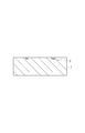
- a soluble resin composition is applied to the substrate 1 to form an ink flow path pattern layer 3a (Fig. 4B).
- a method of forming the ink flow path pattern layer 3a may include dissolving a positive-type photosensitive resin in an appropriate solvent, applying the solution to the substrate 1 by spin coating or any other method, and then heating the coating to form the ink flow path pattern layer 3a.
- the thickness of the ink flow path pattern layer 3a may be such that an ink flow path with the desired height can be formed, which is preferably, but not limited to, 2 to 50 micrometers.
- the ink flow path pattern layer 3 is then irradiated with radiation and developed, so that an ink flow path pattern 3b is formed (Fig. 4C).
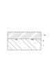
- An ink flow path forming layer 4 is then formed on the ink flow path pattern 3b and the substrate 1 using the photosensitive resin composition according to an exemplary embodiment of the present invention.
- the thickness of the ink flow path forming layer 4 on the ink flow path pattern 3b is preferably 2 micrometers or more.
- the upper limit of the thickness of the ink flow path forming layer 4 on the ink flow path pattern 3b is preferably 100 micrometers or less, while it is not particularly restricted as long as it is in the range where the developability for the ink discharge ports is not reduced.
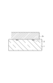
- the ink flow path forming layer 4 is irradiated with radiation, then developed with methyl isobutyl ketone (MIBK) or the like, and further subjected to a rinse treatment with IPA or the like, so that ink discharge ports 5 are formed (Fig. 4D).
- an ink supply port 6 is formed by an appropriate method such as etching (Fig. 4E).
- the ink flow path pattern 3b is then dissolved and removed using an appropriate solvent (Fig. 4F).
- the solvent to be used may be an aqueous alkali solution or an organic solvent.
- the substrate 1 is cut and separated into chips using a dicing saw or any other means, and electrical bonding is performed on each chip so that the energy generation elements 2 can be driven.
- a chip tank component for ink supply is further attached thereto, so that an inkjet recording head is completed.
- Photosensitive resin compositions each containing a polyfunctional epoxy resin (the component (a)), a photoacid generating agent (the component (b)), a solvent, and optionally the component (c), the component (d), and/or a sensitizer were prepared according to the formulations (in units of parts by weight) illustrated in Table 1.
- Concerning the component (b), Table 1 indicates the chemical formulae of the anionic and cationic parts in the Components column.
- the solvent used was a mixed solvent of propylene glycol monomethyl ether acetate and propylene carbonate (25:1 in weight ratio), and 80 parts by weight of the solvent was added to 100 parts by weight of the component (a).
- Each of these photosensitive resin compositions was applied to a supporting material of a silicon wafer using a spin coater and then dried by prebaking at 90 degrees Celsius for 5 minutes, so that a photosensitive resin composition layer with a thickness of 20 micrometers was obtained.
- the resin composition layer was subjected to pattern exposure through a mask having the desired pattern using FPA-3000i5+ (trade name of an i-line stepper manufactured by Cannon Inc.) and then subjected to post-exposure baking at 90 degrees Celsius for 4 minutes using a hot plate. Development was then performed using CDS-630+ (trade name, manufactured by Cannon Inc.). After the development, the patterned resin on the substrate was subjected to post baking at 140 degrees Celsius for 1 hour using an oven, so that a cured resist pattern was obtained on the supporting material.
- Comparative Examples 1 to 3 were performed using a photoacid generating agent containing a sulfonium salt (b1-27) (as an alternative to the component (b)), which does not contain an organic group selected from a thioxanthone skeleton, a 9,10-dialkoxyanthracene skeleton, or an anthraquinone skeleton and in which all the constituent atoms for R 1 to R 3 contain only one oxygen atom.
- Comparative Example 4 was performed using a photoacid generating agent containing a sulfonium salt (b1-28) (as an alternative to the component (b)), which does not contain an organic group selected from a thioxanthone skeleton, a 9,10-dialkoxyanthracene skeleton, or an anthraquinone skeleton and in which all the constituent atoms for R 1 to R 3 contain no oxygen atom.
- a photoacid generating agent containing a sulfonium salt (b1-28) (as an alternative to the component (b)
- a negative-type resist pattern was formed by transferring a model pattern having an elliptic nozzle port pattern with a design size of 20 micrometers (major axis) * 16 micrometers (minor axis) and a bridge line pattern (represented by c in Fig. 1) with a width of 3 micrometers across the ellipse along the minor axis.
- i-line exposure was performed with the amount of light exposure gradually changed in the range of 500 to 20,000 J/m 2 , and the amount of light exposure required to form the pattern with the design size was determined.
- the part at which the bridge line pattern intersects with the ellipse was observed using a scanning electron microscope (SEM), when the resolution was determined.
- a virtual straight line was drawn from an end (represented by a in Fig. 1) of the crescent shape, which will be formed if the resist pattern is formed according to the design of the mask pattern, along the edge of the bridge line pattern.
- the shaping accuracy (in units of micrometers) was defined as the length (represented by b in Fig. 1) of the virtual straight line drawn to the point where it intersects with the actually developed pattern. If the actually developed pattern reaches the end (a in Fig. 1) of the crescent shape, the shaping accuracy will be 0 micrometer, which means that the pattern accords with the design size. However, as the shaping accuracy degrades, the cured material remains at the end (a in Fig. 1) of the crescent shape. Thus, the shaping accuracy value is determined by how much the cured material spreads.
- composition 2 A photosensitive resin composition was obtained by the same method as described above, except that the component (b) was not added.
- compositions 1 and 2 were each applied to a supporting material of quartz glass using a spin coater and then dried by prebaking at 90 degrees Celsius for 5 minutes, so that resin composition layers 1 and 2 with a thickness of about 20 micrometers were each obtained.
- the absorbance (in units of Abs) of each of the resin composition layers 1 and 2 was measured at a wavelength of 365 nm using a spectrophotometer Model U-3300 (trade name, manufactured by Hitachi Ltd.).
- the thickness of each of the resin composition layers 1 and 2 was also measured (in units of micrometers).
- the ratio of the amount of 365 nm wavelength light absorbed by the component (b) to the amount of 365 nm wavelength light absorbed by the photosensitive resin composition was calculated from the measurement results according to the formula below. The calculated value is called the absorption ratio (in units of %).
- a-1 EPICLON N-865 (trade name, manufactured by DIC Corporation) with an epoxy equivalent of 210 and a softening point of 68 degrees Celsius
- a-2 JER157S70 (trade name, manufactured by Japan Epoxy Resins Co., Ltd.) with an epoxy equivalent of 210 and a softening point of 70 degrees Celsius
- a-3 EHPE 3150 (trade name, manufactured by DAICEL CHEMICAL INDUSTRIES, LTD) with an epoxy equivalent of 180 and a softening point of 85 degrees Celsius (b1-27):
- the model pattern for a droplet discharge port was successfully formed with a small amount of light exposure of 4,000 J/m 2 or less. At this time, the shaping accuracy was as fine as 2.0 micrometers or less.
- the photosensitive resin composition according to an exemplary embodiment of the present invention is suitable for use in the production of various micro-fabricated devices for MEMS and other systems.
Landscapes
- Physics & Mathematics (AREA)
- General Physics & Mathematics (AREA)
- Engineering & Computer Science (AREA)
- Manufacturing & Machinery (AREA)
- Spectroscopy & Molecular Physics (AREA)
- Chemical & Material Sciences (AREA)
- Organic Chemistry (AREA)
- Materials For Photolithography (AREA)
- Particle Formation And Scattering Control In Inkjet Printers (AREA)
- Exposure And Positioning Against Photoresist Photosensitive Materials (AREA)
- Micromachines (AREA)
- Compositions Of Macromolecular Compounds (AREA)
Priority Applications (5)
| Application Number | Priority Date | Filing Date | Title |
|---|---|---|---|
| CN201180008124.9A CN102754028B (zh) | 2010-02-05 | 2011-02-01 | 感光性树脂组合物、结构体的生产方法和液体排出头 |
| US13/576,895 US8980968B2 (en) | 2010-02-05 | 2011-02-01 | Photosensitive resin composition, method for producing structure, and liquid discharge head |
| RU2012137721/04A RU2526258C2 (ru) | 2010-02-05 | 2011-02-01 | Светочувствительная полимерная композиция, способы получения структуры и головка для подачи жидкости |
| EP11739545.9A EP2531890B1 (en) | 2010-02-05 | 2011-02-01 | Photosensitive resin composition, method for producing structure, and liquid discharge head |
| EP16000494.1A EP3064996B1 (en) | 2010-02-05 | 2011-02-01 | Liquid discharge head |
Applications Claiming Priority (2)
| Application Number | Priority Date | Filing Date | Title |
|---|---|---|---|
| JP2010-024681 | 2010-02-05 | ||
| JP2010024681 | 2010-02-05 |
Publications (1)
| Publication Number | Publication Date |
|---|---|
| WO2011096195A1 true WO2011096195A1 (en) | 2011-08-11 |
Family
ID=44355213
Family Applications (1)
| Application Number | Title | Priority Date | Filing Date |
|---|---|---|---|
| PCT/JP2011/000549 WO2011096195A1 (en) | 2010-02-05 | 2011-02-01 | Photosensitive resin composition, method for producing structure, and liquid discharge head |
Country Status (6)
| Country | Link |
|---|---|
| US (1) | US8980968B2 (ja) |
| EP (2) | EP3064996B1 (ja) |
| JP (1) | JP5822477B2 (ja) |
| CN (1) | CN102754028B (ja) |
| RU (1) | RU2526258C2 (ja) |
| WO (1) | WO2011096195A1 (ja) |
Cited By (3)
| Publication number | Priority date | Publication date | Assignee | Title |
|---|---|---|---|---|
| CN103728836A (zh) * | 2012-09-15 | 2014-04-16 | 罗门哈斯电子材料有限公司 | 生酸剂化合物和含有其的光致抗蚀剂组合物 |
| US20140329175A1 (en) * | 2012-01-31 | 2014-11-06 | Cannon Kabushiki Kaisha | Photosensitive negative resin composition, fine structure, production process of fine structure and liquid ejection head |
| US9707757B2 (en) | 2013-04-10 | 2017-07-18 | Canon Kabushiki Kaisha | Photosensitive negative resin composition |
Families Citing this family (6)
| Publication number | Priority date | Publication date | Assignee | Title |
|---|---|---|---|---|
| JP5787720B2 (ja) * | 2010-12-16 | 2015-09-30 | キヤノン株式会社 | 感光性ネガ型樹脂組成物 |
| JP6278367B2 (ja) * | 2014-05-13 | 2018-02-14 | 東洋合成工業株式会社 | オニウム塩、光酸発生剤、感光性樹脂組成物及びデバイスの製造方法 |
| WO2017212963A1 (ja) * | 2016-06-09 | 2017-12-14 | サンアプロ株式会社 | スルホニウム塩、光酸発生剤、硬化性組成物およびレジスト組成物 |
| US9938136B2 (en) * | 2016-08-18 | 2018-04-10 | Stmicroelectronics Asia Pacific Pte Ltd | Fluid ejection device |
| US20190056659A1 (en) * | 2017-08-21 | 2019-02-21 | Funai Electric Co., Ltd. | Method for manufacturing mems devices using multiple photoacid generators in a composite photoimageable dry film |
| JP7413039B2 (ja) | 2020-01-22 | 2024-01-15 | キヤノン株式会社 | 液体吐出ヘッド及び液体吐出ヘッドの製造方法 |
Citations (14)
| Publication number | Priority date | Publication date | Assignee | Title |
|---|---|---|---|---|
| JPS5156885A (ja) | 1974-09-18 | 1976-05-18 | Ici Ltd | Hikarijugoseisoseibutsu |
| JPH08157510A (ja) | 1994-12-09 | 1996-06-18 | Nippon Kayaku Co Ltd | 光重合開始剤、これを含有するエネルギー線硬化性組成物及びその硬化物 |
| JPH0912615A (ja) | 1995-06-29 | 1997-01-14 | Nippon Kayaku Co Ltd | エネルギー線硬化性組成物及びその硬化物 |
| JPH107680A (ja) | 1996-06-18 | 1998-01-13 | Nippon Kayaku Co Ltd | 光重合開始剤、これを含有するエネルギー線硬化性組成物及びその硬化物 |
| JPH10152554A (ja) | 1996-11-21 | 1998-06-09 | Nippon Kayaku Co Ltd | エネルギー線硬化性組成物及びその硬化物 |
| JPH10212286A (ja) | 1997-01-30 | 1998-08-11 | Nippon Kayaku Co Ltd | 光重合開始剤、これを含有するエネルギー線硬化性組成物及びその硬化物 |
| JP2000321416A (ja) | 1999-05-10 | 2000-11-24 | Jsr Corp | カラーフィルタ用感放射線性組成物およびそれを用いたカラーフィルタ |
| US6155673A (en) | 1990-04-27 | 2000-12-05 | Canon Kabushiki Kaisha | Recording method and apparatus for controlling ejection bubble formation |
| JP2005187799A (ja) | 2003-11-04 | 2005-07-14 | Natl Starch & Chem Investment Holding Corp | スルホニウム塩光反応開始剤とその使用 |
| JP2006241384A (ja) | 2005-03-07 | 2006-09-14 | Fuji Photo Film Co Ltd | インク組成物、インクジェット記録方法、印刷物、平版印刷版及びその製造方法 |
| JP2008173971A (ja) | 2006-12-22 | 2008-07-31 | Canon Inc | 光カチオン重合性エポキシ樹脂組成物、液体吐出ヘッド、およびその製造方法 |
| JP2008256980A (ja) | 2007-04-05 | 2008-10-23 | Tokyo Ohka Kogyo Co Ltd | 感光性樹脂組成物、レジストパターンの製造方法、積層体、及びデバイス |
| JP2009269849A (ja) | 2008-05-06 | 2009-11-19 | San Apro Kk | スルホニウム塩、光酸発生剤、光硬化性組成物及びこの硬化体 |
| WO2010143560A1 (ja) * | 2009-06-08 | 2010-12-16 | 三洋化成工業株式会社 | 感光性組成物 |
Family Cites Families (20)
| Publication number | Priority date | Publication date | Assignee | Title |
|---|---|---|---|---|
| GB1526923A (en) | 1974-09-18 | 1978-10-04 | Ici Ltd | Photopolymerisable compositions |
| JPH0412859A (ja) | 1990-04-28 | 1992-01-17 | Canon Inc | 液体噴射方法、該方法を用いた記録ヘッド及び該方法を用いた記録装置 |
| US5639802A (en) * | 1991-05-20 | 1997-06-17 | Spectra Group Limited, Inc. | Cationic polymerization |
| JPH07145346A (ja) | 1993-11-22 | 1995-06-06 | Dainippon Ink & Chem Inc | ソルダーレジストインキ用樹脂組成物 |
| JPH0925393A (ja) | 1995-05-09 | 1997-01-28 | Toray Ind Inc | 繊維強化複合材料用エポキシ樹脂組成物、プリプレグおよび繊維強化複合材料 |
| WO1997047660A1 (fr) | 1996-06-12 | 1997-12-18 | Nippon Kayaku Kabushiki Kaisha | Initiateur de photopolymerisation et composition durcissable par rayonnement actinique comprenant cet initiateur |
| JPH11322900A (ja) | 1998-03-19 | 1999-11-26 | Nippon Soda Co Ltd | 光硬化性組成物および硬化方法 |
| WO2001096958A2 (en) | 2000-06-15 | 2001-12-20 | 3M Innovative Properties Company | Process for producing microfluidic articles |
| JP3978601B2 (ja) * | 2001-09-27 | 2007-09-19 | 信越化学工業株式会社 | 化学増幅レジスト材料及びパターン形成方法 |
| JP3880912B2 (ja) | 2002-10-10 | 2007-02-14 | ジャパンエポキシレジン株式会社 | 半導体封止用エポキシ樹脂組成物 |
| JP4593309B2 (ja) | 2005-01-21 | 2010-12-08 | 東京応化工業株式会社 | 精密微細空間の天板部形成方法 |
| JP2007034153A (ja) | 2005-07-29 | 2007-02-08 | Toyo Ink Mfg Co Ltd | 感エネルギー線重合性組成物およびそれを用いたネガ型レジストおよびそれを用いた画像パターン形成方法。 |
| JP4355725B2 (ja) | 2006-12-25 | 2009-11-04 | 信越化学工業株式会社 | ポジ型レジスト材料及びパターン形成方法 |
| JP2008292993A (ja) | 2007-04-24 | 2008-12-04 | Ricoh Co Ltd | 画像形成装置 |
| JP5039442B2 (ja) | 2007-06-15 | 2012-10-03 | 東京応化工業株式会社 | 感光性樹脂組成物、感光性樹脂積層体、及びパターン形成方法 |
| JP4998112B2 (ja) | 2007-06-27 | 2012-08-15 | 住友化学株式会社 | 化学増幅型ポジ型レジスト組成物 |
| JP2010276623A (ja) | 2008-03-26 | 2010-12-09 | Panasonic Electric Works Co Ltd | 立体基板上に透明樹脂構造体を形成させる方法 |
| JP2009244779A (ja) | 2008-03-31 | 2009-10-22 | Fujifilm Corp | ネガ型レジスト組成物及びパターン形成方法 |
| JP2009258506A (ja) | 2008-04-18 | 2009-11-05 | Fujifilm Corp | ネガ型レジスト組成物およびレジストパターン形成方法 |
| JP5247396B2 (ja) | 2008-07-02 | 2013-07-24 | 日本化薬株式会社 | Mems用感光性樹脂組成物及びその硬化物 |
-
2011
- 2011-02-01 WO PCT/JP2011/000549 patent/WO2011096195A1/en active Application Filing
- 2011-02-01 EP EP16000494.1A patent/EP3064996B1/en active Active
- 2011-02-01 EP EP11739545.9A patent/EP2531890B1/en active Active
- 2011-02-01 CN CN201180008124.9A patent/CN102754028B/zh active Active
- 2011-02-01 US US13/576,895 patent/US8980968B2/en active Active
- 2011-02-01 RU RU2012137721/04A patent/RU2526258C2/ru not_active IP Right Cessation
- 2011-02-03 JP JP2011021767A patent/JP5822477B2/ja active Active
Patent Citations (15)
| Publication number | Priority date | Publication date | Assignee | Title |
|---|---|---|---|---|
| JPS5156885A (ja) | 1974-09-18 | 1976-05-18 | Ici Ltd | Hikarijugoseisoseibutsu |
| US6155673A (en) | 1990-04-27 | 2000-12-05 | Canon Kabushiki Kaisha | Recording method and apparatus for controlling ejection bubble formation |
| JPH08157510A (ja) | 1994-12-09 | 1996-06-18 | Nippon Kayaku Co Ltd | 光重合開始剤、これを含有するエネルギー線硬化性組成物及びその硬化物 |
| JPH0912615A (ja) | 1995-06-29 | 1997-01-14 | Nippon Kayaku Co Ltd | エネルギー線硬化性組成物及びその硬化物 |
| JPH107680A (ja) | 1996-06-18 | 1998-01-13 | Nippon Kayaku Co Ltd | 光重合開始剤、これを含有するエネルギー線硬化性組成物及びその硬化物 |
| JPH10152554A (ja) | 1996-11-21 | 1998-06-09 | Nippon Kayaku Co Ltd | エネルギー線硬化性組成物及びその硬化物 |
| JPH10212286A (ja) | 1997-01-30 | 1998-08-11 | Nippon Kayaku Co Ltd | 光重合開始剤、これを含有するエネルギー線硬化性組成物及びその硬化物 |
| JP2000321416A (ja) | 1999-05-10 | 2000-11-24 | Jsr Corp | カラーフィルタ用感放射線性組成物およびそれを用いたカラーフィルタ |
| JP2005187799A (ja) | 2003-11-04 | 2005-07-14 | Natl Starch & Chem Investment Holding Corp | スルホニウム塩光反応開始剤とその使用 |
| JP2006241384A (ja) | 2005-03-07 | 2006-09-14 | Fuji Photo Film Co Ltd | インク組成物、インクジェット記録方法、印刷物、平版印刷版及びその製造方法 |
| JP2008173971A (ja) | 2006-12-22 | 2008-07-31 | Canon Inc | 光カチオン重合性エポキシ樹脂組成物、液体吐出ヘッド、およびその製造方法 |
| JP2008256980A (ja) | 2007-04-05 | 2008-10-23 | Tokyo Ohka Kogyo Co Ltd | 感光性樹脂組成物、レジストパターンの製造方法、積層体、及びデバイス |
| JP2009269849A (ja) | 2008-05-06 | 2009-11-19 | San Apro Kk | スルホニウム塩、光酸発生剤、光硬化性組成物及びこの硬化体 |
| WO2010143560A1 (ja) * | 2009-06-08 | 2010-12-16 | 三洋化成工業株式会社 | 感光性組成物 |
| EP2441778A1 (en) | 2009-06-08 | 2012-04-18 | Sanyo Chemical Industries, Ltd. | Photosensitive composition |
Cited By (4)
| Publication number | Priority date | Publication date | Assignee | Title |
|---|---|---|---|---|
| US20140329175A1 (en) * | 2012-01-31 | 2014-11-06 | Cannon Kabushiki Kaisha | Photosensitive negative resin composition, fine structure, production process of fine structure and liquid ejection head |
| US9268222B2 (en) * | 2012-01-31 | 2016-02-23 | Canon Kabushiki Kaisha | Photosensitive negative resin composition, fine structure, production process of fine structure and liquid ejection head |
| CN103728836A (zh) * | 2012-09-15 | 2014-04-16 | 罗门哈斯电子材料有限公司 | 生酸剂化合物和含有其的光致抗蚀剂组合物 |
| US9707757B2 (en) | 2013-04-10 | 2017-07-18 | Canon Kabushiki Kaisha | Photosensitive negative resin composition |
Also Published As
| Publication number | Publication date |
|---|---|
| RU2012137721A (ru) | 2014-03-10 |
| RU2526258C2 (ru) | 2014-08-20 |
| CN102754028B (zh) | 2015-06-03 |
| EP3064996B1 (en) | 2020-07-22 |
| JP2011180586A (ja) | 2011-09-15 |
| US8980968B2 (en) | 2015-03-17 |
| JP5822477B2 (ja) | 2015-11-24 |
| EP2531890A1 (en) | 2012-12-12 |
| US20120292412A1 (en) | 2012-11-22 |
| EP2531890B1 (en) | 2019-08-28 |
| EP3064996A1 (en) | 2016-09-07 |
| CN102754028A (zh) | 2012-10-24 |
| EP2531890A4 (en) | 2013-11-06 |
Similar Documents
| Publication | Publication Date | Title |
|---|---|---|
| US8980968B2 (en) | Photosensitive resin composition, method for producing structure, and liquid discharge head | |
| JP5247138B2 (ja) | 液体吐出ヘッドの製造方法 | |
| JP5159823B2 (ja) | 構造体の製造方法および液体吐出ヘッドの製造方法 | |
| RU2495468C1 (ru) | Негативная фоточувствительная полимерная композиция, способ формирования паттерна и головка для выбрасывания жидкости | |
| US8944580B2 (en) | Photosensitive resin composition, method for manufacturing structural body, and liquid discharge head | |
| JP5787720B2 (ja) | 感光性ネガ型樹脂組成物 | |
| JP2017121787A (ja) | 基材上に部分撥液領域を形成する方法 | |
| JP4533256B2 (ja) | 微細構造体の製造方法および液体吐出ヘッドの製造方法 | |
| US9707757B2 (en) | Photosensitive negative resin composition | |
| US10265960B2 (en) | Method for manufacturing liquid ejection head | |
| US20080213596A1 (en) | Photosensitive Laminate Film for Forming Top Plate Portion of Precision Fine Space and Method of Forming Precision Fine Space |
Legal Events
| Date | Code | Title | Description |
|---|---|---|---|
| WWE | Wipo information: entry into national phase |
Ref document number: 201180008124.9 Country of ref document: CN |
|
| 121 | Ep: the epo has been informed by wipo that ep was designated in this application |
Ref document number: 11739545 Country of ref document: EP Kind code of ref document: A1 |
|
| WWE | Wipo information: entry into national phase |
Ref document number: 2011739545 Country of ref document: EP |
|
| WWE | Wipo information: entry into national phase |
Ref document number: 6524/CHENP/2012 Country of ref document: IN |
|
| WWE | Wipo information: entry into national phase |
Ref document number: 13576895 Country of ref document: US |
|
| NENP | Non-entry into the national phase |
Ref country code: DE |
|
| WWE | Wipo information: entry into national phase |
Ref document number: 2012137721 Country of ref document: RU |