WO2011036968A1 - X線ct装置 - Google Patents
X線ct装置 Download PDFInfo
- Publication number
- WO2011036968A1 WO2011036968A1 PCT/JP2010/063988 JP2010063988W WO2011036968A1 WO 2011036968 A1 WO2011036968 A1 WO 2011036968A1 JP 2010063988 W JP2010063988 W JP 2010063988W WO 2011036968 A1 WO2011036968 A1 WO 2011036968A1
- Authority
- WO
- WIPO (PCT)
- Prior art keywords
- ray
- detector
- scattered
- collimator
- focal point
- Prior art date
- Legal status (The legal status is an assumption and is not a legal conclusion. Google has not performed a legal analysis and makes no representation as to the accuracy of the status listed.)
- Ceased
Links
Images


Classifications
-
- A—HUMAN NECESSITIES
- A61—MEDICAL OR VETERINARY SCIENCE; HYGIENE
- A61B—DIAGNOSIS; SURGERY; IDENTIFICATION
- A61B6/00—Apparatus or devices for radiation diagnosis; Apparatus or devices for radiation diagnosis combined with radiation therapy equipment
- A61B6/02—Arrangements for diagnosis sequentially in different planes; Stereoscopic radiation diagnosis
- A61B6/03—Computed tomography [CT]
- A61B6/032—Transmission computed tomography [CT]
-
- A—HUMAN NECESSITIES
- A61—MEDICAL OR VETERINARY SCIENCE; HYGIENE
- A61B—DIAGNOSIS; SURGERY; IDENTIFICATION
- A61B6/00—Apparatus or devices for radiation diagnosis; Apparatus or devices for radiation diagnosis combined with radiation therapy equipment
- A61B6/06—Diaphragms
-
- A—HUMAN NECESSITIES
- A61—MEDICAL OR VETERINARY SCIENCE; HYGIENE
- A61B—DIAGNOSIS; SURGERY; IDENTIFICATION
- A61B6/00—Apparatus or devices for radiation diagnosis; Apparatus or devices for radiation diagnosis combined with radiation therapy equipment
- A61B6/40—Arrangements for generating radiation specially adapted for radiation diagnosis
- A61B6/4021—Arrangements for generating radiation specially adapted for radiation diagnosis involving movement of the focal spot
-
- A—HUMAN NECESSITIES
- A61—MEDICAL OR VETERINARY SCIENCE; HYGIENE
- A61B—DIAGNOSIS; SURGERY; IDENTIFICATION
- A61B6/00—Apparatus or devices for radiation diagnosis; Apparatus or devices for radiation diagnosis combined with radiation therapy equipment
- A61B6/42—Arrangements for detecting radiation specially adapted for radiation diagnosis
- A61B6/4208—Arrangements for detecting radiation specially adapted for radiation diagnosis characterised by using a particular type of detector
-
- A—HUMAN NECESSITIES
- A61—MEDICAL OR VETERINARY SCIENCE; HYGIENE
- A61B—DIAGNOSIS; SURGERY; IDENTIFICATION
- A61B6/00—Apparatus or devices for radiation diagnosis; Apparatus or devices for radiation diagnosis combined with radiation therapy equipment
- A61B6/58—Testing, adjusting or calibrating thereof
Definitions
- the present invention relates to an X-ray CT apparatus.
- An X-ray CT (Computed Tomography) apparatus is an X-ray source that irradiates a subject with X-rays, and an X-ray detector for imaging an object that detects X-rays transmitted through the subject at a position facing the X-ray source.
- an X-ray tube is generally used that generates X-rays by irradiating the anode with electrons accelerated at a high voltage.
- the generation efficiency of X-rays is low with respect to the energy used for accelerating electrons, and most of the energy is changed to heat. Therefore, a phenomenon occurs in which the generation position of the X-ray beam fluctuates due to thermal expansion of the heated anode. .
- a detector for detecting positional deviation of the X-ray focal point has a configuration in which two or more X-ray detector elements are arranged, and the output signal of each X-ray detector element is From the difference, the X-ray irradiation center, that is, the focal position is measured.
- a method of moving the X-ray tube to the irradiation center or a method of moving a collimator that limits the X-ray beam range is used.
- the X-ray CT apparatus of Patent Document 1 and the X-ray CT apparatus of Patent Document 2 are disclosed. Further, as a technique relating to correction of scattered X-rays generated in a subject or the like, for example, a CT scanner disclosed in Patent Document 3 and an X-ray CT apparatus disclosed in Patent Document 4 are disclosed.
- Japanese Patent Laid-Open No. 11-89826 JP 2002-320607 A Japanese Patent Laid-Open No. 08-154926 Japanese Patent Laid-Open No. 08-252248
- Patent Document 4 Japanese Patent Laid-Open No. 08-2522478
- the subject imaging X-ray detector is incident with scattered X-rays scattered by a subject or a structure and becomes a noise source for acquired data.
- scattered X-rays incident on the shift detector lower the accuracy of detecting the positional deviation of the X-ray focal point of the shift detector.
- the scattered X-ray dose varies depending on the size and shape of the subject, it is difficult to estimate the scattered X-ray dose due to the subject before measurement.
- an object of the present invention is to correct the output of the shift detector in accordance with the scattered X-ray dose for each measurement and calculate the X-ray focal position deviation with high accuracy.
- an X-ray CT apparatus includes an X-ray source that generates X-rays from an X-ray focal point, a collimator for shaping the X-rays, and an X-ray transmitted through a subject.
- an X-ray CT apparatus comprising: a main body detector in which a plurality of X-ray detector elements for detection are arranged in a plurality of rows; and a focus movement detection unit that detects movement of the X-ray focal position; A scattered radiation detection unit for measuring the scattered radiation incident on the unit is provided.
- the X-ray CT apparatus According to the X-ray CT apparatus according to the present invention, it is possible to calculate the positional deviation of the X-ray focal point with high accuracy using a shift detector.
- FIG. 1 It is a flowchart which shows the flow of the scattered ray correction process regarding the data of the shift detector in the X-ray CT apparatus which concerns on 3rd embodiment of this invention, and collimator control.
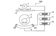
- FIG. 1 is a view of the structure of the X-ray CT apparatus according to the first embodiment of the present invention as seen from the body axis direction.
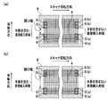
- FIGS. 2A and 2B are views of the structure of the X-ray CT apparatus according to the first embodiment of the present invention as viewed from the X-ray beam irradiation direction.
- FIGS. It is a figure.
- An opening 2 through which the subject 3 can enter is provided at the center of the gantry (not shown) of the X-ray CT apparatus 100.
- the scanner device of the X-ray CT apparatus 100 includes an X-ray tube 1 that is an X-ray source, a collimator 8, and a subject imaging X-ray detector (main body detector 4).
- the center of the gantry is supported so as to be rotatable around the center of rotation. With such a configuration, the subject 3 in the opening 2 can be rotated and imaged.
- ⁇ X-ray tube 1 An X-ray tube 1 as an X-ray source generates X-rays from an X-ray focal point 9 having a finite size in the X-ray tube 1.
- the phenomenon that the anode of the X-ray tube 1 is heated and expands occurs only in the body axis direction (also referred to as the slice direction), and as a result, the X-ray focal point 9 moves only in the body axis direction. To do.
- the collimator 8 is disposed between the X-ray tube 1 and the subject 3, and shapes the X-ray irradiation range so as to irradiate the X-ray only within the range of the subject 3 to be inspected. Play a role to prevent.
- a subject imaging X-ray detector (hereinafter referred to as a main body detector 4) is disposed at a position facing the X-ray tube 1 across the subject 3.
- the main body detector 4 obtains a large number of X-ray transmittance data simultaneously by irradiating the subject 3 with X-rays at a time, so that the X-ray detector elements are in the scanner rotation direction (also referred to as channel direction) and the body axis direction. In contrast, multiple rows and columns are arranged.
- the X-ray detector element indicates a minimum unit capable of specifying the position where X-rays are incident. For example, in the case of an X-ray detector using a scintillator and a diode, the X-ray detection signal is for each diode. Therefore, the X-ray detector element is a unit of a diode.
- the shift detector 5 that detects the movement of the X-ray focal point 9 is a part of a number of X-ray detector elements of the main body detector 4 so as not to be affected by the attenuation of X-rays due to transmission through the subject 3. Are arranged at the end of the main body detector 4 in the scanner rotation direction.
- the shift detector 5 is composed of two or more X-ray detector elements in which the difference in penumbra amount determined by the position and size of the X-ray focal point 9 and the geometric arrangement of the collimator 8 is arranged in the body axis direction. taking measurement. Based on the measured penumbra amount difference, the amount of movement of the X-ray focal point 9 in the body axis direction is calculated.
- penumbra means that the X-ray focal point 9 cannot be treated as an ideal point source and has a width, so that X-rays from a part of the X-ray focal point 9 reach directly, but other parts of the X-ray focal point 9
- the X-rays from the line indicate a state where the X-rays cannot reach directly by the shield.
- a set of shift detectors 5 is disposed at both ends of the main body detector 4 in the scanner rotation direction. Show.
- the scattered X-ray detector 6 is arranged at the outer end in the body axis direction of the shift detector 5 in order to estimate the dose of scattered X-rays incident on the shift detector 5. In order to correctly detect only the scattered rays, a shield that shields the X-rays from the X-ray focal point 9 so as not to directly enter the scattered X-ray detector 6 is necessary.
- the collimator 8 shapes the X-ray irradiation range, and at the same time, is arranged so that X-rays do not directly enter the scattered X-ray detector 6 (a figure to be described later). 14). Therefore, contrary to the shift detector 5, the scattered X-ray detector 6 needs to have a sufficient distance from the shift detector 5 to the outside in the body axis direction so that a penumbra by the collimator 8 does not enter.
- the collimator 8 is used as the X-ray shield of the shift detector 5 and the scattered X-ray detector 6, the X-ray detector element irradiated with the X-ray beam or shielded by the opening width of the collimator 8. Since the X-ray detector elements are different, as shown in FIGS. 2A and 2B, the X-rays that function as the shift detector 5 and the scattered X-ray detector 6 according to the opening width of the collimator 8. Change the detector element.
- the X-ray detector elements responsible for the functions of the shift detector 5 and the scattered X-ray detector 6 may combine data obtained from a plurality of X-ray detector elements into one piece of data. Good. Further, in order to remove the influence of penumbra on the scattered X-ray detector 6, it is used as the scattered X-ray detector 6 and the shift detector 5 between the shift detector 5 and the scattered X-ray detector 6. There may be no X-ray detector elements.
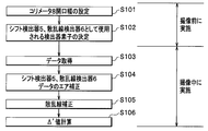
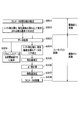
- FIG. 10 is a flowchart showing the flow of the scattered radiation correction process regarding the data of the shift detector in the X-ray CT apparatus according to the first embodiment of the present invention.
- the control device 12 controls the collimator 8 according to the imaging condition of the subject 3 set by the user, and sets the aperture width of the collimator 8.
- the control device 12 sets the opening width of the collimator 8 so that, for example, the entire region of interest of the subject 3 can be irradiated with necessary X-rays.
- X-rays are directly irradiated from the entire region of the X-ray focal point 9 to the end of the region of interest of the subject 3. Is set not to be incident.
- step S102 the arithmetic unit 11 (X-ray CT apparatus 100) determines the position and size of the X-ray focal point 9, the position and size of the collimator 8, and the geometric arrangement of the X-ray detector elements.
- X-ray detector elements that serve as the main body detector 4, the shift detector 5 and the scattered X-ray detector 6 are determined.
- FIG. 14 shows the relationship between the position of the X-ray detector element in the body axis direction and the signal intensity.
- FIG. 14 is a diagram showing an outline of an X-ray intensity profile measured by a shift detector and a scattered X-ray detector in the X-ray CT apparatus according to the first embodiment of the present invention.
- the geometric arrangement of the X-ray focal point 9, the collimator 8, the main body detector 4, the shift detector 5, and the scattered X-ray detector 6 will be described with reference to FIG.
- the X-ray focal spot 9 cannot be treated as an ideal point source and has a width, an area where X-rays are directly incident from the entire area of the X-ray focal spot 9 (direct X-ray area not including a penumbra), and the X-ray focal spot 9 X-rays from one part of the X-rays reach directly, but X-rays from other parts of the X-ray focal point 9 do not reach directly by the shield (collimator 8) and the X-ray focus by the shield (collimator 8). 9, an area where X-rays are not directly incident occurs. As shown in FIG.
- these regions are geometrically determined by the position and size of the X-ray focal point 9, the position and opening width of the collimator 8, and the arrangement of the X-ray detector elements.
- the main body detector 4 is usually arranged in a direct X-ray region not including a penumbra.
- a shift detector 5 is arranged in the penumbra area.
- the scattered X-ray detector 6 is disposed in a region where the X-rays are not directly incident from the X-ray focal point 9, and only the scattered rays not affected by the penumbra are measured.
- the aperture width of the collimator 8 may be narrowed to reduce the exposure, and a part of the penumbra area may be disposed on the main body detector 4.
- the main body detector 4 and the shift detector 5 may be used as one X-ray detector element.
- a part of the shift detector 5 may be arranged so that a direct X-ray region that does not include a penumbra is applied, and X-rays are directly incident on a part of the shift detector 5 from the X-ray focal point 9. It may be arranged such that a region that is not to be covered.
- the scattered X-ray detector 6 is for measuring only the scattered radiation not affected by the penumbra and is arranged so as not to cover the penumbra area.
- X-ray detector elements 5 (a) and 5 (b) that become penumbra areas are determined as the shift detector 5.
- X-rays from the X-ray focal point 9 are shielded by the collimator 8 and are not directly incident, and X-ray detector elements 6 (a) and 6 (b) to which scattered X-rays generated from the subject 3 and the like are incident are scattered X.
- the line detector 6 is determined.
- ⁇ Imaging> Again, the continuation of the flow of the process for correcting the positional deviation of the X-ray focal spot 9 will be described with reference to FIG.
- the X-ray CT apparatus 100 After determining the X-ray detector elements to be used as the shift detector 5 and the scattered X-ray detector 6 (step S102), the X-ray CT apparatus 100 proceeds to imaging of the subject 3. During imaging, X-rays are generated at the position of the X-ray focal point 9 and the X-ray irradiation area is shaped by the collimator 8.
- X-rays transmitted through the subject 3 are detected by the main body detector 4, and a data processing system (recording device 10, arithmetic device 11, control device 12) of the X-ray CT apparatus 100 using signals corresponding to the X-ray intensity as data. (See FIG. 1) and reconstructed as an image.
- a data processing system recording device 10, arithmetic device 11, control device 12
- the data processing system of the X-ray CT apparatus 100 (the recording device 10, the arithmetic device 11, and the control device 12) simultaneously acquires the data of the shift detector 5 and the scattered X-ray detector 6 (step S103).
- the position shift of the X-ray focal point 9 is obtained from the data acquired from the shift detector 5 and the scattered X-ray detector 6 (steps S103 to S106). A method for obtaining the positional deviation amount of the X-ray focal point 9 will be described below.
- step S ⁇ b> 104 the arithmetic device 11 reads out data (air data) captured in the absence of the subject 3 stored in advance in the storage device 10 from the storage device 10, and shift detector 5 and scattered X-ray detector 6.
- the data acquired from the above is standardized with air data, so that correction processing (air correction) for correcting sensitivity variations between X-ray detector elements is performed.
- the shift detector 5 is composed of two or more X-ray detector elements, as shown in FIGS. 14 (a) and 5 (b) with respect to the main body detector 4, the body axis Data after air correction of the X-ray detector element 5 (a) on the negative side of the direction is averaged. Similarly, the data after air correction of the X-ray detector element 5 (b) on the positive side in the body axis direction is averaged.
- the averaged data value is A for the X-ray detector element 5 (a) in FIG. 14 and B for the X-ray detector element 5 (b) in FIG.
- the body detector 4 has a body as shown in 6 (a) and 6 (b) in FIG.
- the data after air correction of the X-ray detector element 6 (a) on the negative side in the axial direction is averaged.
- the data after air correction of the X-ray detector element 6 (b) on the positive side in the body axis direction is averaged.
- the averaged data value is C for the X-ray detector element 6 (a) in FIG. 14 and D for the X-ray detector element 6 (b) in FIG.
- 5 (a), 5 (b), 6 (a), and 6 (b) in FIG. 14 represent the X-ray detector elements at the ends in the scanner rotation direction.
- the statistical accuracy of scattered radiation detection can be improved by using data captured at different scanner rotation angles (views). Specifically, the average of neighboring view data may be taken assuming that the scattered radiation distribution is gentle.
- data measured by the scattered X-ray detector 6 at the end on the positive side in the body axis direction at a certain scanner rotation angle (view) and the body at the scanner rotation angle (view) after one scanner rotation can be improved by taking the average of the data measured by the scattered X-ray detector 6 at the end on the negative side in the axial direction.
- the statistical accuracy can be improved by averaging the outputs of the scattered X-ray detector 6 before and after one rotation. In this case, the statistical accuracy improves as the scanner rotation speed increases.
- ⁇ is defined in the form of (Expression 1) as an amount representing the positional deviation of the X-ray focal point 9.
- a ′ A ⁇ C (Formula 4)
- B ′ BD (Expression 5)
- the amount ⁇ ′ representing the positional deviation of the X-ray focal point 9 is calculated using the following (Equation 6) (step S106).
- the following effects are obtained by the X-ray CT apparatus 100 according to the first embodiment of the present invention.
- (Effect 1) By using the ⁇ ′ value, it is possible to correct / remove the influence of scattered X-rays, particularly scattered X-rays that change every measurement from the subject 3, and calculate the positional deviation of the X-ray focal spot 9 with higher accuracy. be able to.
- (Effect 2) The X-ray detection is divided into a penumbra region important for detecting the positional deviation of the X-ray focal point 9 and a region where direct X-rays necessary for detecting scattered rays are not incident, and each region is arranged at an appropriate position.
- the accuracy of detecting the positional deviation of the X-ray focal point 9 can be improved by adding the data of the instrument elements as necessary. (Effect 3)
- the cost of separately creating the shift detector 5 and the scattered X-ray detector 6 can be reduced.
- it is expected that maintenance labor such as arrangement adjustment can be reduced.
- the following control of the collimator 8 may be performed based on the focal position information obtained here.
- the X-ray irradiation range incident on the main body detector 4 can be adjusted by controlling the collimator 8 in real time during imaging in accordance with the positional shift of the X-ray focal point that changes every moment. In order to perform the adjustment more accurately, the focal position information can be used.
- FIG. 11 is a flowchart showing a flow of scattered radiation correction processing and collimator control regarding data of the shift detector in the X-ray CT apparatus according to the first embodiment of the present invention.
- step S151 to step S156 is the same as that from step S101 to step S106 in FIG.
- Step S151 corresponds to Step S101
- Step S152 corresponds to Step S102
- Step S153 corresponds to Step S103
- Step S154 corresponds to Step S104
- Step S155 corresponds to Step S105
- Step S156 corresponds to Step S106.
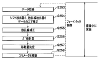
- step S157 the arithmetic unit 11 determines the movement amount of the collimator 8 from the ⁇ ′ value obtained in step S156.
- the amount of movement of the collimator 8 can be obtained, for example, by multiplying the ⁇ ′ value by an optimal proportionality constant for each scanning condition that has been measured in advance.
- step S158 the control device 12 can move the penumbra position by shifting the position of the collimator 8 using the feedback circuit.
- a control method of the X-ray irradiation field using the feedback circuit will be described below.
- the output A is obtained.
- the movement of the collimator 8 changes the ⁇ ′ value dynamically during imaging and is controlled so as to converge to ⁇ ′ ⁇ 0, so the accuracy of estimating the optimal proportionality constant can be reduced. This makes it possible to control the X-ray field more quickly and accurately.
- the subject 3 enters between the X-ray focal point 9 and the shift detector 5 in imaging of the large subject 3 or off-center imaging in which the body axis of the subject 3 is shifted with respect to the scanner rotation axis.
- a measure such as not using the ⁇ ′ value at that time may be taken.
- subject fogging occurs in all the shift detectors 5, it is preferable to take measures such as not performing the collimator 8 control at that time.
- all X-ray detector element arrays in the body axis direction where no subject fogging may occur may be used as an X-ray detector element array having the shift detector 5 and the scattered X-ray detector 6.
- a statistic can be increased and accuracy can be improved.
- the determination of subject fogging is made based on, for example, whether or not the dose after the reference correction of the X-ray detector element serving as the main body detector 4 inside the shift detector 5 is less than an appropriate threshold value. . Note that the threshold value changes according to the required determination accuracy.
- the reference correction is a process of correcting gain fluctuations typified by voltage fluctuations of the X-ray tube 1 when air data is acquired and when the subject 3 is imaged. This is data (average of both ends) measured by the X-ray detector element at the end of the main body detector 4 in the direction of rotation of the scanner, which can directly detect X-rays without passing through the subject 3, and each slice. This is done by normalizing the measurement data of the rows (rows of X-ray detector elements arranged in the scanner rotation direction). However, the reference correction may be performed using the average value of the end element data of a plurality of slices within a range where the gain fluctuation for each slice row can be ignored.
- the collimator 8 is used as an X-ray shield.
- X-ray detector elements used as the shift detector 5 and the scattered X-ray detector 6 are X-rays shielded by the collimator 8. Only the detector elements at both ends of the scanner rotation direction are included.
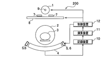
- FIG. 3 and 4 show an X-ray CT apparatus 200 according to the second embodiment of the present invention.
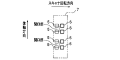
- FIG. 3 is a view of the structure of the X-ray CT apparatus according to the second embodiment of the present invention viewed from the body axis direction.
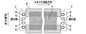
- FIG. 4 is a view of the structure of the X-ray CT apparatus according to the second embodiment of the present invention as seen from the X-ray beam irradiation direction.
- the basic configuration is the same as that of the X-ray CT apparatus 100 according to the first embodiment, and the same components are denoted by the same reference numerals and description thereof is omitted.
- the slit 7 which is an X-ray shield having an opening for passing X-rays in the center of the body axis is detected with the X-ray focal point 9 and shift detection. Between the detector 5 and the scattered X-ray detector 6. The shift detector 5 and the scattered X-ray detector 6 are provided separately from the main body detector 4.
- the shift detector 5 uses two or more X-ray detector elements arranged in the body axis direction to detect the difference in penumbra amount determined by the X-ray focal point 9 position and its size and the geometrical arrangement of the slits 7. By measuring, the movement amount ⁇ ′ of the X-ray focal point 9 in the body axis direction is calculated.
- the scattered X-ray detector 6 is disposed at the outer end in the body axis direction of the shift detector 5 in order to estimate the dose of scattered X-rays incident on the shift detector 5.
- the scattered X-ray detector 6 requires an X-ray shield so that X-rays do not enter directly.
- the slit 7 is also used.
- the scattered X-ray detector 6 needs to have a sufficient distance from the shift detector 5 to the outside in the body axis direction so that a penumbra due to the slit 7 does not enter.
- the shift detector 5 needs to have a sufficient size on the outer side in the body axis direction, or consist of a sufficiently large number of X-ray detector elements.
- the shift detector 5 and the scattered X-ray detector 6 are provided separately from the main body detector 4 as described above, the shift detector 5 and the scattered X-ray detector 6 according to the opening width of the collimator 8.
- the X-ray detector element having the above function does not change.
- the shift detector 5 and the scattered X-ray detector 6 may be arranged only at one end on one side of the main body detector 4 in the scanner rotation direction.
- FIG. 5 is a diagram showing an outline of the structure when there are a plurality of openings in the slit in the X-ray CT apparatus according to the second embodiment of the present invention.
- FIG. 5 by providing a plurality of openings in the slit 7, it may be devised to increase the statistical accuracy.
- the shift detector 5, the scattered X-ray detector 6, and the main body detector 4 shown in FIGS. 3, 4, and 5 may be adjacent to each other.
- a plurality of X-ray detector elements that function as the shift detector 5 and the scattered X-ray detector 6 may be provided, and the obtained data may be combined into one data.
- FIG. 5 is a diagram showing an outline of the structure when there are a plurality of openings in the slit in the X-ray CT apparatus according to the second embodiment of the present invention.
- the slit 7 is disposed between the X-ray focal point 9 and the collimator 8, but the scattered X-ray dose incident on the shift detector 5 and the scattered X-ray dose incident on the scattered X-ray detector 6 are substantially equal. Therefore, the X-ray directly incident on the main body detector 4 is not obstructed, the X-ray directly incident on the scattered X-ray detector 6 can be shielded, and the object 3 is disposed at a position that does not get in the way when entering the opening 2. do it.
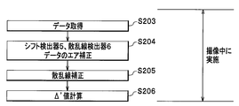
- FIG. 12 is a flowchart showing the flow of scattered radiation correction processing and collimator control regarding the data of the shift detector in the X-ray CT apparatus according to the second embodiment of the present invention.
- FIG. 15 is a diagram showing an outline of an X-ray intensity profile measured by a shift detector and a scattered X-ray detector in the X-ray CT apparatus according to the second embodiment of the present invention.
- Step S203 corresponds to Step S103
- Step S204 corresponds to Step S104
- Step S205 corresponds to Step S105
- Step S206 corresponds to Step S106.
- the X-ray detector elements responsible for the functions of the shift detector 5 and the scattered X-ray detector 6 are different depending on the opening width of the collimator 8.
- X-ray detector elements to be used as the detector 5 and the scattered X-ray detector 6 have been determined (see step S101 and step S102 in FIG. 10).
- the X-ray CT apparatus 200 according to the second embodiment Since the X-ray detector elements used as the shift detector 5 and the scattered X-ray detector 6 are predetermined, the X-ray detector elements used as the shift detector 5 and the scattered X-ray detector 6 There is no processing to determine.
- the primary or secondary scattered radiation back is provided for the shift detector 5 arranged in a portion sandwiched between the plurality of scattered X-ray detectors 6. It is also possible to correct by assuming the ground.
- the X-ray CT apparatus 200 has the following effects in addition to (Effect 1) and (Effect 2) included in the X-ray CT apparatus 100 according to the first embodiment.
- (Effect 6) Regardless of the opening width of the collimator 8, constant data control is possible.
- (Effect 7) By separately providing X-ray detector elements used as the shift detector 5 and the scattered X-ray detector 6, unused X-ray detector elements can be minimized. That is, the end slice row of the main body detector 4 can be used for imaging the subject 3 to the maximum extent.
- FIG. 13 is a flowchart showing the flow of scattered radiation correction processing and collimator control regarding the data of the shift detector in the X-ray CT apparatus according to the second embodiment of the present invention.
- step S253 to step S256 is the same as that from step S203 to step S206 in FIG. 12.
- the flow from step S257 and step S258 may be processed in the same manner as in FIG. Note that step S253 corresponds to step S203, step S254 corresponds to step S204, step S255 corresponds to step S205, step S256 corresponds to step S206, step S257 corresponds to step S157, and step S258 corresponds to step S158.
- the slit 7 of the X-ray CT apparatus 200 according to the second embodiment moves in synchronization with the control of the collimator 8, and the center of the slit 7 in the body axis direction always coincides with the opening center of the collimator 8.
- the arrangement shall be as follows.
- the X-ray CT apparatus 100 according to the first embodiment and the X-ray CT apparatus 200 according to the second embodiment have the X-ray tube 1 and the main body instead of controlling the collimator 8 by the control device 12.
- the X-ray irradiation field can also be feedback controlled by moving the detector 4 (including the shift detector 5 and the scattered X-ray detector 6).
- the slit 7 of the X-ray CT apparatus 200 according to the second embodiment is not synchronized with the collimator 8 and has a fixed arrangement.
- FIG. 6 is a view of the structure of an X-ray CT apparatus according to a modification of the second embodiment of the present invention as seen from the body axis direction.
- FIG. 7 is a view of the structure of an X-ray CT apparatus according to a modification of the second embodiment of the present invention as seen from the X-ray beam irradiation direction.
- FIG. 8 is a diagram showing an outline of the structure in the case where there are a plurality of openings in the slit in the X-ray CT apparatus according to the modification of the second embodiment of the present invention.
- the scattered X-ray detector 6 is arranged in the body axis direction of the shift detector 5, but the scattered X-ray detector 6 may be arranged in the scanner rotation direction. Is possible.
- the scattered X-ray detector 6 may be arranged at both ends of the shift detector 5 in the scanner rotation direction.
- FIG. 3 can be read as FIG. 6,
- FIG. 4 can be read as FIG. FIG. 13 is common.
- FIG. 15 may be read with reference to FIG.
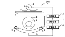
- FIG. 9 shows an outline of the structure when the X-ray CT apparatus according to the second embodiment of the present invention and the X-ray CT apparatus according to a modification of the second embodiment of the present invention are combined.
- the scattered X-ray detector 6 is arranged at both the outer end in the body axis direction of the shift detector 5 and the outer end in the scanner rotation direction so as to improve the estimation accuracy of the scattered dose. Also good.
- An X-ray CT apparatus 201 includes (Effect 1), (Effect 2), (Effect 4), and (Effects) of the X-ray CT apparatus 100 according to the first embodiment.
- (Effect 6) and (Effect 7) included in the X-ray CT apparatus 200 according to 5) and the second embodiment the following effects can be obtained.
- (Effect 8) Even if the collimator 8 and the slit 7 move in the body axis direction, the penumbra amount does not change in the scanner rotation direction. Therefore, the shift detector 5 and the scattered X-ray detector 6 can be arranged close to each other, and the difference in the scattered X-ray dose incident on the shift detector 5 and the scattered X-ray detector 6 can be minimized.
- the X-ray CT apparatus 200 according to the second embodiment has the following advantages over the X-ray CT apparatus 201 according to the modification of the second embodiment. (Effect 9) By arranging the shift detector 5 and the scattered X-ray detector 6 in the body axis direction, the arrangement of the detectors becomes compact.
- ⁇ Third embodiment As a method of creating a penumbra on the shift detector 5, a method using the collimator 8 as in the first embodiment and a method of providing the slit 7 as in the second embodiment are combined. Can do. Further, by the method described below, both the X-ray focal point 9 position shift detection and the reference correction can be performed using the same X-ray detector element array at the scanner rotation direction end of the main body detector 4.
- FIG. 16 is a view of the structure of the X-ray CT apparatus according to the third embodiment of the present invention as seen from the body axis direction.
- FIG. 17 is a view of the structure of the X-ray CT apparatus according to the third embodiment of the present invention as viewed from the X-ray beam irradiation direction, and (a), (b), and (c) have different collimator opening widths. It is the figure which showed the case. Note that the shift detector 5 and scattered X-ray detector 6 on the left side (scanning rotation direction negative side) in FIG. 17 are omitted.
- the basic configuration is the same as in the first embodiment and the second embodiment.
- the shift detector 5 and the scattered X-ray detector 6 are arranged at the end of the scanner rotation direction as a part of the main body detector 4, and the scattered X-ray detector 6 is
- the shift detector 5 is disposed at the outer end in the body axis direction.
- the X-ray detector elements that function as the shift detector 5 and the scattered X-ray detector 6 change according to the opening width of the collimator 8.
- the gain fluctuation amount due to the penumbra is the same between the main body detector 4 that is the subject 3 imaging unit and the end of the scanner rotation direction, and can be corrected correctly.
- the shift detector 5 is set to a portion where the penumbra of the slit 7 enters, and the scattered X-ray detector 6. Is set outside the penumbra area. That is, the same method as in the second embodiment is performed.
- the reference data can be acquired without any problem including the slice row at the end of the X-ray irradiation range where the sensitivity change is most severe except for the portion behind the slit 7. For the slice row that is shaded by the slit 7, the data near the center that is considered not to have a penumbra is extrapolated as reference data.
- the total amount of penumbra irradiation by the slit 7 (the total value of A and B detected by the shift detector 5) is considered not to change much by the collimator 8 control.
- Reference correction is performed for slice columns other than the end portion of the X-ray irradiation range with the sum of data obtained from elements other than the slice column at the end of the irradiation range.
- the settings of the shift detector 5 and the scattered X-ray detector 6 are as shown in FIG. It is possible as in b).
- the sensitivity change of the edge part (X-ray irradiation range end part) of the collimator 8 with the most rapid sensitivity change cannot be acquired. Therefore, when the reference data acquisition is also used, the setting of the collimator 8 opening width used for imaging and the slit 7 so that the opening width of the collimator 8 and the slit 7 do not take the arrangement as shown in FIG. It is necessary to decide the shape. Alternatively, it is necessary to set the opening width of the collimator 8 to be slightly wider so that no penumbra enters the imaging region.
- FIG. 18 is a flowchart showing the flow of scattered radiation correction processing and collimator control regarding the data of the shift detector in the X-ray CT apparatus according to the third embodiment of the present invention.
- the scattered radiation correction process (step S305) and the collimator control process (step S308) in the third embodiment are performed in the same manner as in the first embodiment.
- the basic flow is the same as that of the first embodiment, and FIG. 1 may be read as FIG. 16, FIG. 2 as FIG. 17, and FIG.
- Step S301 is Step S151
- Step S302 is Step S152
- Step S303 is Step S153
- Step S304 is Step S154
- Step S305 is Step S155
- Step S306 is Step S156
- Step S307 is Step S157.
- Step S308 corresponds to step S158.
- step S302 the determination of the X-ray detector elements used as the shift detector 5 and the scattered X-ray detector 6 is determined by the relationship between the opening width of the collimator 8 and the slit 7 as described above (step S302). FIG. 17). Further, as shown in FIG. 18, a process of storing data obtained from the shift detector 5 and the scattered X-ray detector 6 in the storage device 10 for use as reference data is added (step S309).
- the control method of the collimator 8 using the focal movement information ( ⁇ ′ value) is the same as that of the second embodiment, and the slit 7 of the X-ray CT apparatus 300 controls the collimator 8. The arrangement moves so that the center of the opening in the body axis direction of the slit 7 always coincides with the center of the opening of the collimator 8.
- the X-ray CT apparatus 300 according to the third embodiment includes (Effect 1), (Effect 2), (Effect 3), (Effect 4), which the X-ray CT apparatus 100 according to the first embodiment includes.
- (Effect 10) Since reference data can also be acquired at the same time, correction using reference data becomes possible. In particular, the reference correction can be correctly performed for the X-ray detector element array of the X-ray irradiation range end slice shaped by the collimator 8.
- X-ray tube (X-ray source) 2 Opening 3 Subject 4 X-ray detector for imaging the subject (main body detector) 5 X-ray focus shift detector (shift detector) (focus shift detector) 6 Scattered X-ray detector (scattered radiation detector) 7 Slit 8 Collimator 9 X-ray Focus 10 Storage Device 11 Computing Device 12 Control Device (Movement Mechanism)
Landscapes
- Health & Medical Sciences (AREA)
- Life Sciences & Earth Sciences (AREA)
- Engineering & Computer Science (AREA)
- Medical Informatics (AREA)
- Radiology & Medical Imaging (AREA)
- Molecular Biology (AREA)
- Biophysics (AREA)
- Nuclear Medicine, Radiotherapy & Molecular Imaging (AREA)
- Optics & Photonics (AREA)
- Pathology (AREA)
- Physics & Mathematics (AREA)
- Biomedical Technology (AREA)
- Heart & Thoracic Surgery (AREA)
- High Energy & Nuclear Physics (AREA)
- Surgery (AREA)
- Animal Behavior & Ethology (AREA)
- General Health & Medical Sciences (AREA)
- Public Health (AREA)
- Veterinary Medicine (AREA)
- Pulmonology (AREA)
- Theoretical Computer Science (AREA)
- Apparatus For Radiation Diagnosis (AREA)
Priority Applications (1)
| Application Number | Priority Date | Filing Date | Title |
|---|---|---|---|
| US13/391,074 US8774350B2 (en) | 2009-09-28 | 2010-08-19 | X-ray CT device |
Applications Claiming Priority (2)
| Application Number | Priority Date | Filing Date | Title |
|---|---|---|---|
| JP2009223336A JP5134606B2 (ja) | 2009-09-28 | 2009-09-28 | X線ct装置 |
| JP2009-223336 | 2009-09-28 |
Publications (1)
| Publication Number | Publication Date |
|---|---|
| WO2011036968A1 true WO2011036968A1 (ja) | 2011-03-31 |
Family
ID=43795727
Family Applications (1)
| Application Number | Title | Priority Date | Filing Date |
|---|---|---|---|
| PCT/JP2010/063988 Ceased WO2011036968A1 (ja) | 2009-09-28 | 2010-08-19 | X線ct装置 |
Country Status (3)
| Country | Link |
|---|---|
| US (1) | US8774350B2 (enExample) |
| JP (1) | JP5134606B2 (enExample) |
| WO (1) | WO2011036968A1 (enExample) |
Cited By (4)
| Publication number | Priority date | Publication date | Assignee | Title |
|---|---|---|---|---|
| WO2013190440A1 (en) * | 2012-06-20 | 2013-12-27 | Koninklijke Philips N.V. | Image-based determination of source detector spatial relation |
| US20140153691A1 (en) * | 2012-11-30 | 2014-06-05 | General Electric Company | Radiation focal position detecting method, radiation detecting apparatus and radiation tomographic imaging apparatus |
| CN104605873A (zh) * | 2011-03-07 | 2015-05-13 | 佳能株式会社 | X射线摄像设备以及控制x射线摄像的控制设备和方法 |
| CN113552640A (zh) * | 2020-04-02 | 2021-10-26 | 同方威视技术股份有限公司 | 射线检查系统及散射校正方法 |
Families Citing this family (21)
| Publication number | Priority date | Publication date | Assignee | Title |
|---|---|---|---|---|
| WO2014163187A1 (ja) * | 2013-04-04 | 2014-10-09 | 株式会社 東芝 | X線コンピュータ断層撮影装置 |
| JP2015092953A (ja) * | 2013-11-11 | 2015-05-18 | キヤノン株式会社 | 放射線撮影装置及び放射線撮影システム |
| US10117632B2 (en) * | 2016-02-03 | 2018-11-06 | Globus Medical, Inc. | Portable medical imaging system with beam scanning collimator |
| US10433811B2 (en) | 2016-12-23 | 2019-10-08 | General Electric Company | Self-calibrating CT detectors, systems and methods for self-calibration |
| CN108937976B (zh) * | 2017-05-27 | 2024-06-21 | 上海西门子医疗器械有限公司 | X射线系统、测量x射线管的焦点的偏移的方法、准直器 |
| US10445886B2 (en) * | 2017-05-30 | 2019-10-15 | General Electric Company | Motion-gated medical imaging |
| EP3420908A1 (en) * | 2017-06-27 | 2019-01-02 | Koninklijke Philips N.V. | Scattered x-ray detection to detect misuse and prevent harm |
| CN107682452B (zh) * | 2017-10-31 | 2020-12-29 | 东软医疗系统股份有限公司 | 一种数据处理方法、装置及系统 |
| JP6987631B2 (ja) * | 2017-12-19 | 2022-01-05 | キヤノンメディカルシステムズ株式会社 | X線ct装置及び画像生成方法 |
| CN109431534B (zh) * | 2018-11-30 | 2022-12-06 | 深圳安科高技术股份有限公司 | 一种射线准直器的自校准方法及其系统 |
| WO2020112673A1 (en) * | 2018-11-30 | 2020-06-04 | Accuray Inc. | Method and apparatus for improving scatter estimation and correction in imaging |
| CN109730712B (zh) * | 2018-12-28 | 2022-08-09 | 深圳安科高技术股份有限公司 | 一种ct球管焦点跟踪方法及其系统 |
| JP7534123B2 (ja) * | 2020-05-12 | 2024-08-14 | キヤノンメディカルシステムズ株式会社 | X線検出器及びx線ct装置 |
| CN111728632B (zh) * | 2020-07-31 | 2023-08-15 | 上海联影医疗科技股份有限公司 | 射线探测装置、射线探测方法和ct图像重建方法 |
| JP7619776B2 (ja) | 2020-09-11 | 2025-01-22 | キヤノンメディカルシステムズ株式会社 | X線撮影制御装置 |
| WO2023277900A1 (en) * | 2021-06-30 | 2023-01-05 | Accuray, Inc. | Anchored kernel scatter estimate |
| US11794039B2 (en) | 2021-07-13 | 2023-10-24 | Accuray, Inc. | Multimodal radiation apparatus and methods |
| US11854123B2 (en) | 2021-07-23 | 2023-12-26 | Accuray, Inc. | Sparse background measurement and correction for improving imaging |
| US12257083B2 (en) | 2022-02-07 | 2025-03-25 | Accuray Inc. | Methods for saturation correction and dynamic gain configuration and apparatuses for performing the same |
| JP2024048207A (ja) * | 2022-09-27 | 2024-04-08 | キヤノンメディカルシステムズ株式会社 | X線ct装置 |
| CN117462160A (zh) * | 2023-11-29 | 2024-01-30 | 上海联影医疗科技股份有限公司 | 放射源的位置跟踪装置、方法和计算机断层成像设备 |
Citations (4)
| Publication number | Priority date | Publication date | Assignee | Title |
|---|---|---|---|---|
| JPH08252248A (ja) * | 1995-03-16 | 1996-10-01 | Toshiba Corp | X線ct装置 |
| JPH10211199A (ja) * | 1997-01-31 | 1998-08-11 | Toshiba Corp | X線ct装置 |
| JPH1170103A (ja) * | 1997-08-29 | 1999-03-16 | Shimadzu Corp | X線撮像装置 |
| JPH1189826A (ja) * | 1997-09-17 | 1999-04-06 | Shimadzu Corp | X線ct装置 |
Family Cites Families (8)
| Publication number | Priority date | Publication date | Assignee | Title |
|---|---|---|---|---|
| JPH0712948A (ja) * | 1993-06-28 | 1995-01-17 | Hitachi Medical Corp | 散乱線検出器及び散乱線・線質検出装置 |
| JP3408848B2 (ja) * | 1993-11-02 | 2003-05-19 | 株式会社日立メディコ | 散乱x線補正法及びx線ct装置並びに多チャンネルx線検出器 |
| JP2825450B2 (ja) | 1994-12-06 | 1998-11-18 | 株式会社東芝 | Ctスキャナ |
| JP4897151B2 (ja) | 2001-04-26 | 2012-03-14 | 株式会社日立メディコ | X線ct装置 |
| EP1926431B1 (en) * | 2005-09-13 | 2014-07-02 | Philips Intellectual Property & Standards GmbH | Direct measuring and correction of scatter for ct |
| US8761342B2 (en) * | 2008-12-08 | 2014-06-24 | Koninklijke Philips N.V. | Compensation of anode wobble for X-ray tubes of the rotary-anode type |
| US8262288B2 (en) * | 2010-01-21 | 2012-09-11 | Analogic Corporation | Focal spot position determiner |
| US8891727B2 (en) * | 2012-02-24 | 2014-11-18 | General Electric Company | Radiation imaging apparatus, radiation detecting apparatus and radiation focal-point movement detecting method |
-
2009
- 2009-09-28 JP JP2009223336A patent/JP5134606B2/ja not_active Expired - Fee Related
-
2010
- 2010-08-19 US US13/391,074 patent/US8774350B2/en not_active Expired - Fee Related
- 2010-08-19 WO PCT/JP2010/063988 patent/WO2011036968A1/ja not_active Ceased
Patent Citations (4)
| Publication number | Priority date | Publication date | Assignee | Title |
|---|---|---|---|---|
| JPH08252248A (ja) * | 1995-03-16 | 1996-10-01 | Toshiba Corp | X線ct装置 |
| JPH10211199A (ja) * | 1997-01-31 | 1998-08-11 | Toshiba Corp | X線ct装置 |
| JPH1170103A (ja) * | 1997-08-29 | 1999-03-16 | Shimadzu Corp | X線撮像装置 |
| JPH1189826A (ja) * | 1997-09-17 | 1999-04-06 | Shimadzu Corp | X線ct装置 |
Cited By (5)
| Publication number | Priority date | Publication date | Assignee | Title |
|---|---|---|---|---|
| CN104605873A (zh) * | 2011-03-07 | 2015-05-13 | 佳能株式会社 | X射线摄像设备以及控制x射线摄像的控制设备和方法 |
| WO2013190440A1 (en) * | 2012-06-20 | 2013-12-27 | Koninklijke Philips N.V. | Image-based determination of source detector spatial relation |
| US20140153691A1 (en) * | 2012-11-30 | 2014-06-05 | General Electric Company | Radiation focal position detecting method, radiation detecting apparatus and radiation tomographic imaging apparatus |
| US9271683B2 (en) * | 2012-11-30 | 2016-03-01 | General Electric Company | Radiation focal position detecting method, radiation detecting apparatus and radiation tomographic imaging apparatus |
| CN113552640A (zh) * | 2020-04-02 | 2021-10-26 | 同方威视技术股份有限公司 | 射线检查系统及散射校正方法 |
Also Published As
| Publication number | Publication date |
|---|---|
| JP5134606B2 (ja) | 2013-01-30 |
| US8774350B2 (en) | 2014-07-08 |
| US20120170708A1 (en) | 2012-07-05 |
| JP2011067555A (ja) | 2011-04-07 |
Similar Documents
| Publication | Publication Date | Title |
|---|---|---|
| JP5134606B2 (ja) | X線ct装置 | |
| US8873703B2 (en) | X ray imaging system with scatter radiation correction and method of using same | |
| US6639964B2 (en) | Device and method for forming a computed X-ray tomogram with scatter correction | |
| JP3408848B2 (ja) | 散乱x線補正法及びx線ct装置並びに多チャンネルx線検出器 | |
| US7440536B2 (en) | Method for scattered radiation correction of a CT system | |
| US8077826B2 (en) | CT scanner with scatter radiation correction and method of using same | |
| US8699659B2 (en) | Systems and methods for focal spot motion correction | |
| US8761483B2 (en) | Calibration system for focal spot shift in an X-ray CT device | |
| JP3961468B2 (ja) | 放射線計算断層画像装置およびそれに用いる放射線検出器 | |
| JP2007296338A (ja) | X線コンピュータ断層撮影装置における散乱放射線補正方法およびx線コンピュータ断層撮影装置 | |
| JP6378470B2 (ja) | 線源側放射線検出器、イメージング・システム及び撮像データを補正する方法 | |
| KR20160094880A (ko) | 좁은 시야 x선 이미징 시스템 및 방법 | |
| KR20050025914A (ko) | 방사선 단층 촬영 장치 및 그 방사선 단층 촬영 방법 | |
| JP6307268B2 (ja) | Ctシステムで使用するためのコリメータ | |
| JP2004000623A (ja) | コンピュータトモグラフの絞り調節方法およびコンピュータトモグラフ | |
| JP3532649B2 (ja) | X線ct装置 | |
| JP2009005922A (ja) | X線ct装置 | |
| JP6777556B2 (ja) | X線ct装置 | |
| JPH1189827A (ja) | X線コンピュータ断層撮影装置 | |
| JP3746148B2 (ja) | 放射線照射位置調節方法および放射線照射・検出装置並びに放射線断層撮影装置 | |
| CN114113173B (zh) | 一种x射线设备、应用于x射线设备中的散射校正方法 | |
| JP2001061831A (ja) | X線ct装置 | |
| JPH11206750A (ja) | 放射線照射位置合わせ方法および放射線照射・検出装置並びに放射線断層撮影装置 | |
| US20090020692A1 (en) | Scattered radiation correction of detector signals for projection-based imaging | |
| IL208958A (en) | X-ray imaging system with scattered radiation correction and method of use |
Legal Events
| Date | Code | Title | Description |
|---|---|---|---|
| 121 | Ep: the epo has been informed by wipo that ep was designated in this application |
Ref document number: 10818644 Country of ref document: EP Kind code of ref document: A1 |
|
| WWE | Wipo information: entry into national phase |
Ref document number: 13391074 Country of ref document: US |
|
| NENP | Non-entry into the national phase |
Ref country code: DE |
|
| 122 | Ep: pct application non-entry in european phase |
Ref document number: 10818644 Country of ref document: EP Kind code of ref document: A1 |